Embed Size (px)
Citation preview
A702-11-880Issue H Original
Instruction Manual
Drystar® GV80 Dry Vacuum Pumps
Description Electrical Supply Item Number
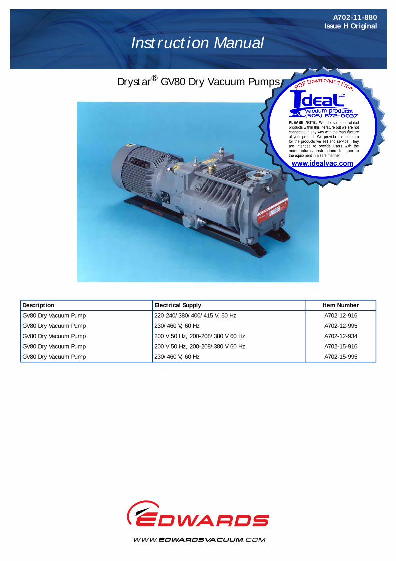
GV80 Dry Vacuum Pump 220-240/380/400/415 V, 50 Hz A702-12-916
GV80 Dry Vacuum Pump 230/460 V, 60 Hz A702-12-995
GV80 Dry Vacuum Pump 200 V 50 Hz, 200-208/380 V 60 Hz A702-12-934
GV80 Dry Vacuum Pump 200 V 50 Hz, 200-208/380 V 60 Hz A702-15-916
GV80 Dry Vacuum Pump 230/460 V, 60 Hz A702-15-995
P900-77-000 Issue A
© Edwards Limited 2009. All rights reserved. Page iEdwards and the Edwards logo are trademarks of Edwards Limited.
ContentsA702-11-880 Issue H
Contents
Section Page
1 Introduction ....................................................................................... 1
1.1 Scope and definitions ................................................................................................... 11.2 The GV pumps ............................................................................................................ 11.3 Gas system ................................................................................................................ 21.4 Cooling system ........................................................................................................... 41.5 Motor over-temperature protection .................................................................................. 41.6 Liquid pumping capability .............................................................................................. 41.7 Safe area operation ..................................................................................................... 41.8 Accessories ................................................................................................................ 4
2 Technical data .................................................................................... 5
2.1 General .................................................................................................................... 52.2 Materials of construction ............................................................................................... 52.3 Services .................................................................................................................... 82.4 Cooling system ........................................................................................................... 92.5 Lubrication system ...................................................................................................... 92.5.1 Gearbox ................................................................................................................... 92.5.2 High vacuum bearings ................................................................................................... 92.6 Area classification in accordance with BS 5345 ..................................................................... 9
3 Installation ....................................................................................... 11
3.1 Safety .....................................................................................................................113.2 Unpack and inspect .....................................................................................................113.3 Locate the pump ........................................................................................................123.4 Check the gearbox oil-level ...........................................................................................123.5 Electrical connections ..................................................................................................123.5.1 Introduction .............................................................................................................143.5.2 Connect to the pump-motor terminal-box ..........................................................................143.5.3 Connect to the thermal snap-switches ..............................................................................153.6 Check the direction of pump rotation ...............................................................................173.7 Fit a mechanical booster pump (optional) ..........................................................................173.8 Connect the cooling-water supply ...................................................................................173.9 Connect the shaft-seals purge and gas-ballast gas supplies ......................................................183.9.1 Introduction .............................................................................................................183.9.2 Connect the shaft-seals purge air or nitrogen supply .............................................................183.9.3 Connect a nitrogen gas-ballast supply (optional) ..................................................................193.10 Connect the pump-inlet and pump-outlet ..........................................................................203.10.1 Connect the pump to your process system .........................................................................203.10.2 Connect the pump-outlet ..............................................................................................213.11 Leak test the installation ..............................................................................................213.12 Commission the pump ..................................................................................................22
4 Operation ........................................................................................ 23
4.1 Start the pump ..........................................................................................................234.2 Check the purge pressures and flows ................................................................................244.3 Shut down the pump ...................................................................................................24
5 Maintenance ..................................................................................... 25
5.1 Safety .....................................................................................................................255.2 Maintenance plan .......................................................................................................25
dcs/
8268
/020
9
A702-11-880 Issue H
Page ii © Edwards Limited 2009. All rights reserved.Edwards and the Edwards logo are trademarks of Edwards Limited.
Contents
5.3 Check the gearbox oil-level and fill the gearbox with oil (if necessary) .......................................265.4 Inspect the gas-ballast system ........................................................................................275.5 Inspect the pipelines and connections ..............................................................................275.6 Change the gearbox oil and clean the oil-level sight-glass .......................................................295.7 Relubricate the high vacuum bearings ..............................................................................305.8 Flush the cooling jacket ...............................................................................................325.9 Replace the gas ballast filter .........................................................................................325.10 Replace the pump-motor bearings ...................................................................................335.11 Overhaul the pump .....................................................................................................335.12 Fault finding .............................................................................................................34
6 Storage and disposal ........................................................................... 35
6.1 Storage ...................................................................................................................356.2 Disposal ...................................................................................................................35
7 Service, spares and accessories .............................................................. 37
7.1 Introduction .............................................................................................................377.2 Service ....................................................................................................................377.3 Spares and maintenance kits ..........................................................................................377.4 Accessories ...............................................................................................................377.4.1 Exhaust silencer .........................................................................................................377.4.2 Booster connection kit .................................................................................................387.4.3 Indirect cooling kit .....................................................................................................387.4.4 Acoustic enclosure ......................................................................................................387.4.5 Other accessories .......................................................................................................38
Appendix A1 Correct use of Swagelok connectors ................................................................................ 39
A1.1 Fit a Swagelok connector ..............................................................................................39A1.2 Reconnect a Swagelok connector ....................................................................................39
For return of equipment, complete the HS Forms at the end of this manual.
Illustrations
Figure Page1 The GV pump: key ....................................................................................................... 22 Dimensions ................................................................................................................ 73 Schematic diagram of the recommended electrical connections ...............................................134 Connect to the thermal snap-switches ..............................................................................165 Oil-level sight-glass and oil filler port ...............................................................................286 Relubricate the high vacuum bearings ..............................................................................31A1 Fit a Swagelok fitting ..................................................................................................40A2 Retighten a Swagelok fitting ..........................................................................................41
© Edwards Limited 2009. All rights reserved. Page iiiEdwards and the Edwards logo are trademarks of Edwards Limited.
ContentsA702-11-880 Issue H
Tables
Table Page1 Technical data: 220-240/380/400/415 V, 50 Hz electrical supplies ............................................. 62 Technical data: 230/460 V, 60 Hz electrical supplies .............................................................. 63 Electrical data ............................................................................................................ 84 Checklist of components ...............................................................................................125 Maintenance plan .......................................................................................................266 Fault finding .............................................................................................................34
Associated publications
Publication title Publication numberVacuum pump and vacuum system safety P300-20-000

This page has been intentionally left blank.
A702-11-880 Issue H
Page iv © Edwards Limited 2009. All rights reserved.Edwards and the Edwards logo are trademarks of Edwards Limited.
© Edwards Limited 2009. All rights reserved. Page 1Edwards and the Edwards logo are trademarks of Edwards Limited.
IntroductionA702-11-880 Issue H
1 Introduction1.1 Scope and definitions
This manual provides installation, operation and maintenance instructions for the Edwards GV80 Dry Vacuum Pump (abbreviated to GV pump in the remainder of this manual). You must use the GV pump as specified in the manual.
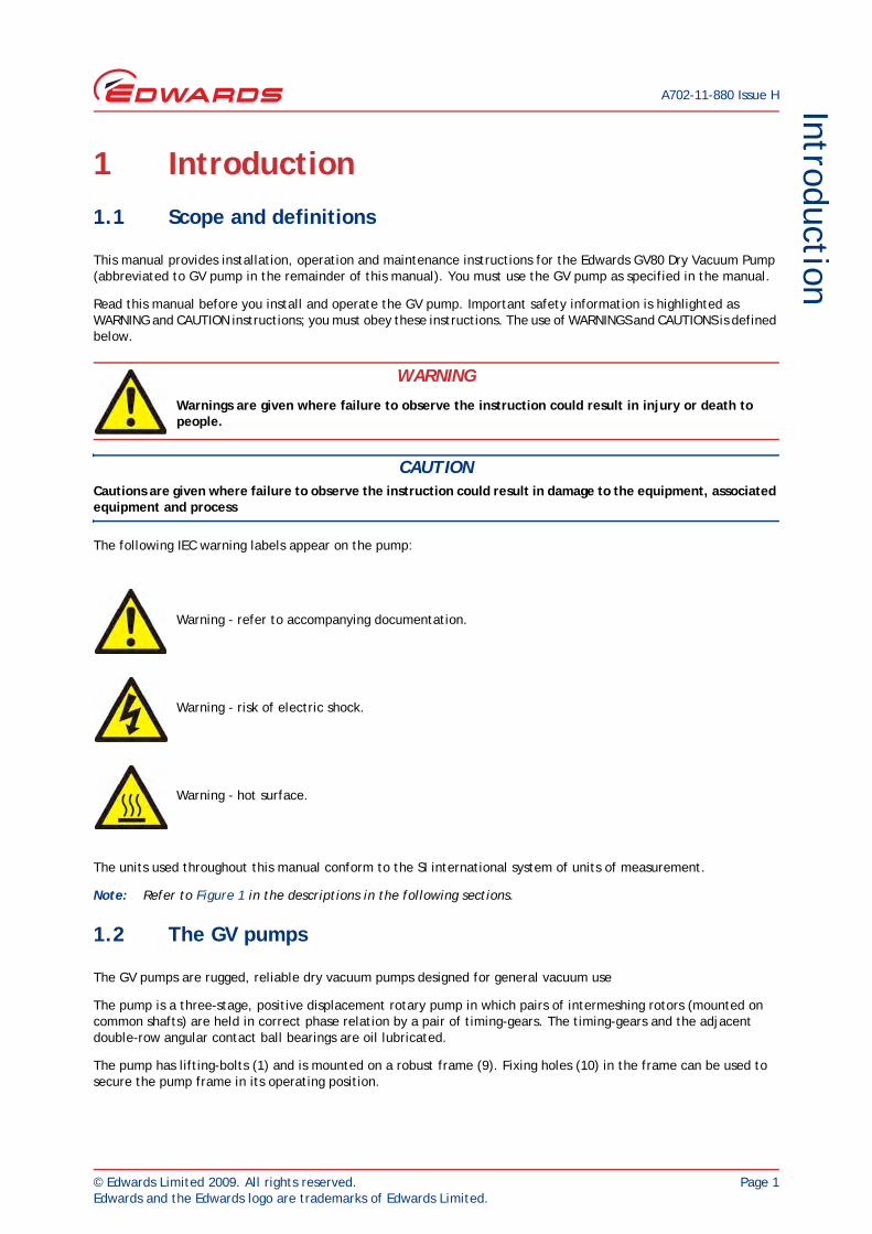
Read this manual before you install and operate the GV pump. Important safety information is highlighted as WARNING and CAUTION instructions; you must obey these instructions. The use of WARNINGS and CAUTIONS is defined below.
CAUTIONCautions are given where failure to observe the instruction could result in damage to the equipment, associated equipment and process
The following IEC warning labels appear on the pump:
The units used throughout this manual conform to the SI international system of units of measurement.
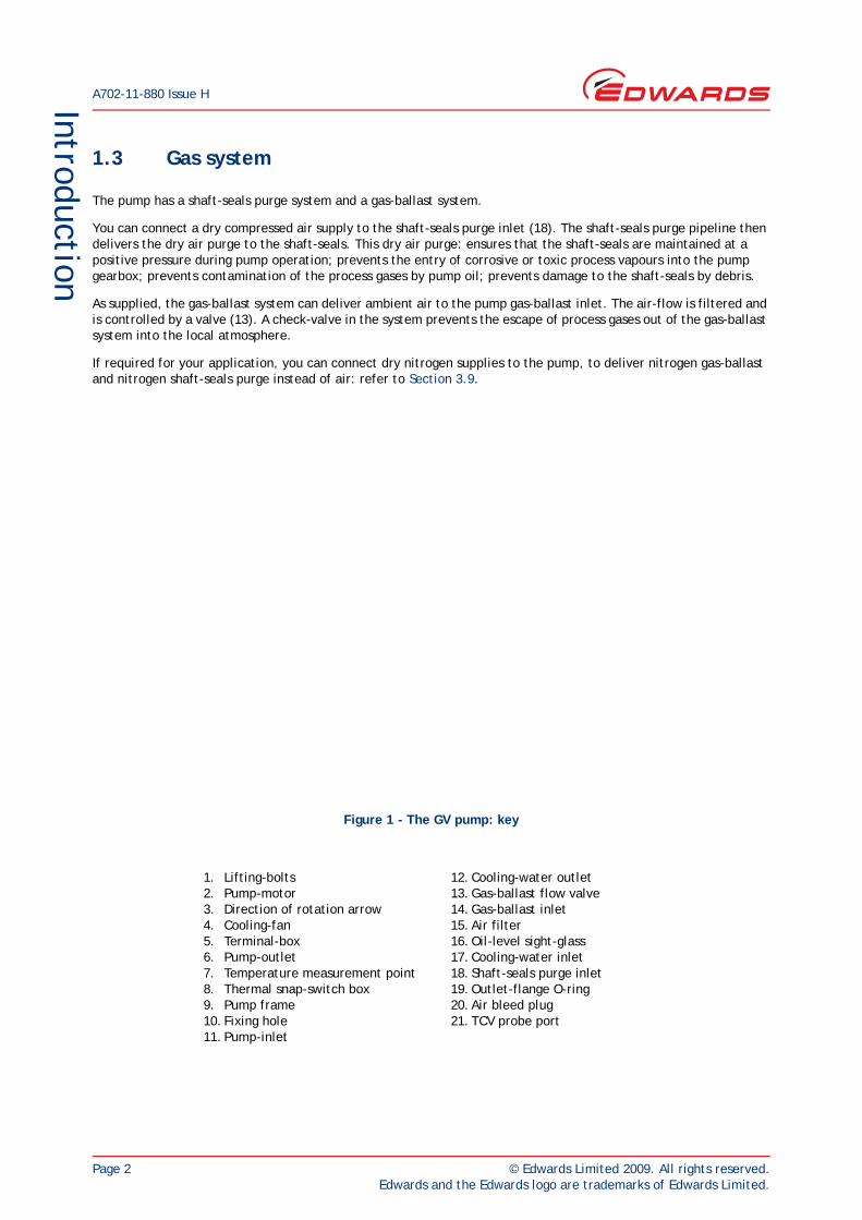
Note: Refer to Figure 1 in the descriptions in the following sections.
1.2 The GV pumps
The GV pumps are rugged, reliable dry vacuum pumps designed for general vacuum use
The pump is a three-stage, positive displacement rotary pump in which pairs of intermeshing rotors (mounted on common shafts) are held in correct phase relation by a pair of timing-gears. The timing-gears and the adjacent double-row angular contact ball bearings are oil lubricated.
The pump has lifting-bolts (1) and is mounted on a robust frame (9). Fixing holes (10) in the frame can be used to secure the pump frame in its operating position.
WARNING
Warnings are given where failure to observe the instruction could result in injury or death to people.
Warning - refer to accompanying documentation.
Warning - risk of electric shock.
Warning - hot surface.
A702-11-880 Issue H
Page 2 © Edwards Limited 2009. All rights reserved.Edwards and the Edwards logo are trademarks of Edwards Limited.
Introduction
1.3 Gas system
The pump has a shaft-seals purge system and a gas-ballast system.
You can connect a dry compressed air supply to the shaft-seals purge inlet (18). The shaft-seals purge pipeline then delivers the dry air purge to the shaft-seals. This dry air purge: ensures that the shaft-seals are maintained at a positive pressure during pump operation; prevents the entry of corrosive or toxic process vapours into the pump gearbox; prevents contamination of the process gases by pump oil; prevents damage to the shaft-seals by debris.
As supplied, the gas-ballast system can deliver ambient air to the pump gas-ballast inlet. The air-flow is filtered and is controlled by a valve (13). A check-valve in the system prevents the escape of process gases out of the gas-ballast system into the local atmosphere.
If required for your application, you can connect dry nitrogen supplies to the pump, to deliver nitrogen gas-ballast and nitrogen shaft-seals purge instead of air: refer to Section 3.9.
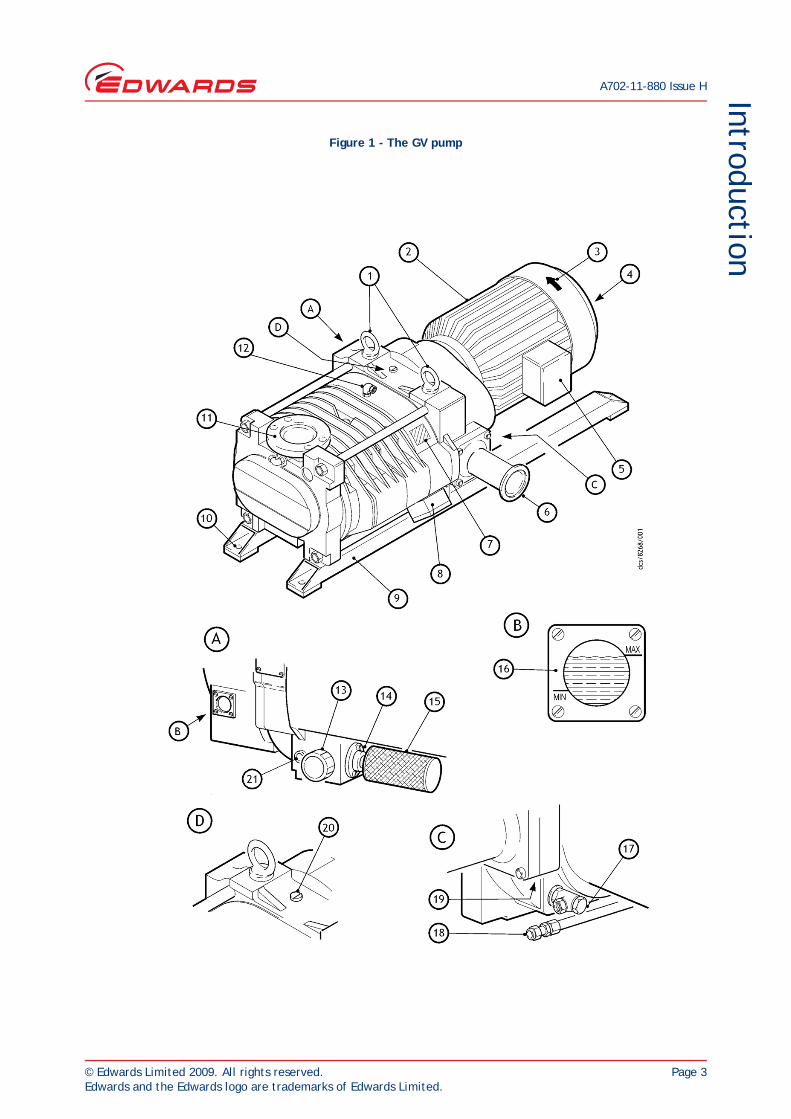
Figure 1 - The GV pump: key
1. Lifting-bolts2. Pump-motor3. Direction of rotation arrow4. Cooling-fan5. Terminal-box6. Pump-outlet7. Temperature measurement point8. Thermal snap-switch box9. Pump frame10. Fixing hole11. Pump-inlet
12. Cooling-water outlet13. Gas-ballast flow valve14. Gas-ballast inlet15. Air filter16. Oil-level sight-glass17. Cooling-water inlet18. Shaft-seals purge inlet19. Outlet-flange O-ring20. Air bleed plug21. TCV probe port
© Edwards Limited 2009. All rights reserved. Page 3Edwards and the Edwards logo are trademarks of Edwards Limited.
IntroductionA702-11-880 Issue H
Figure 1 - The GV pump
A702-11-880 Issue H
Page 4 © Edwards Limited 2009. All rights reserved.Edwards and the Edwards logo are trademarks of Edwards Limited.
Introduction
1.4 Cooling system
Note: The direct cooling system fitted to the pump is suitable for pump operating temperatures (measured at the position shown in Figure 1, item 7) of up to 45 °C, (113 °F). If your application requires pump operating temperatures of 45 to 90 °C (113 to 194 °F), we recommend that you fit an Indirect Cooling Kit accessory: refer to Section 7.4.3.
The pump has a direct cooling system, in which cooling-water (connected through the cooling- water inlet, 17) circulates around the pump-body and then passes out of the pump through the cooling-water outlet (12). The pump-motor (2) is air-cooled by an integral cooling-fan (4).
The thermal snap-switch box (8) on the pump-body has two thermal snap-switches:
The output of the warning thermal snap-switch will go open circuit when the temperature of the pump-body is higher than normal. Use this output to provide a warning of high pump temperature.
The output of the shut-down thermal snap-switch will go open circuit when the temperature of the pump-body is too high. Use this output to shut-down the pump when it is too hot.
1.5 Motor over-temperature protection
A motor-protection thermistor is fitted to the pump-motor. This thermistor is a solid-state device which has a low electrical resistance at normal pump-motor operational temperature. When the pump-motor is too hot, the electrical resistance of the thermistor rises quickly. You can connect the outputs of the thermistor to your control equipment to shut down the pump if the pump-motor is too hot.
1.6 Liquid pumping capability
The GV pump cannot survive the ingress of liquid (after a process failure condition, for example) without damage. If you want to pump liquids, contact your supplier or Edwards for advice.
1.7 Safe area operation
You must not use the GV pump in the following hazardous areas:
Zone 0, Zone 1 or Zone 2 (gases), or Zone Z (10) or Zone Y (11) (dusts), as classified by European authorities.
Division 1 or Division 2 (gases and dusts), as classified by North American authorities.
These hazardous areas require the use of flameproof equipment. If you need a pump which can operate in these areas, contact your supplier or Edwards for advice.
1.8 Accessories
A number of accessories are available for the GV pumps; use these to configure the pump for specific applications. These accessories are listed in Section 7.
© Edwards Limited 2009. All rights reserved. Page 5Edwards and the Edwards logo are trademarks of Edwards Limited.
Technical dataA702-11-880 Issue H
2 Technical data2.1 General
2.2 Materials of construction
Dimensions See Figure 2
Mass See Tables 1 and 2
Pump-motor rating See Tables 1 and 2
Full load and no-load current ratings See Table 3
Typical pump rotation speed
50 Hz electrical supply 3000 rev.min-1
60 Hz electrical supply 3600 rev.min-1
Warm-up time to pump operating temperatureof 40°C (104°F), with a cooling-water flow rateof 150 l.h-1 (33 US gallons.h-1)
15 min
Pump-inlet connection ISO40
Pump-outlet connection NW40
Recommended pump-inlet seal Fluoroelastomer trapped O-ring
Recommended pump-outlet seal Fluoroelastomer trapped O-ring
Ambient operating temperature range 0 to 40°C, 32 to 104°F
Maximum ambient operating humidity 100% RH
Maximum outlet pressure 1.3 bar absolute, 1.3 x 10⁵ Pa, 975 torr
Swept volume maximum pressure rating 11 bar absolute, 1.1 x 10⁶ Pa, 8250 torr
Typical continuous A-weighted sound pressure level See Tables 1 and 2
Performance See Tables 1 and 2
Rotors Grey cast iron, grade 250
Stators Grey cast iron, grade 250
Shafts Carbon steel 817 M40
Sleeves Stainless steel 431 S29
Bearing holders Stainless steel 410 C21
Inlet flange Carbon steel
Outlet flange Grey cast iron, grade 250
Gearbox Grey cast iron, grade 250
Coupling cover Grey cast iron, grade 250
O-rings Fluoroelastomer
Shaft seals Carbon filled PTFE (polytetrafluoroethylene)
Timing gears Carbon steel 817 M40
A702-11-880 Issue H
Page 6 © Edwards Limited 2009. All rights reserved.Edwards and the Edwards logo are trademarks of Edwards Limited.
Technical data
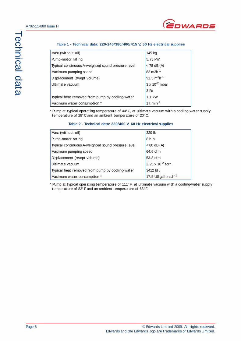
* Pump at typical operating temperature of 44°C, at ultimate vacuum with a cooling-water supply temperature of 28°C and an ambient temperature of 20°C.
* Pump at typical operating temperature of 111°F, at ultimate vacuum with a cooling-water supply temperature of 82°F and an ambient temperature of 68°F.
Table 1 - Technical data: 220-240/380/400/415 V, 50 Hz electrical supplies
Mass (without oil) 145 kg
Pump-motor rating 5.75 kW
Typical continuous A-weighted sound pressure level < 78 dB (A)
Maximum pumping speed 82 m3h-1
Displacement (swept volume) 91.5 m3h-1
Ultimate vacuum 3 x 10⁻² mbar
3 Pa
Typical heat removed from pump by cooling-water 1.1 kW
Maximum water consumption * 1 l.min-1
Table 2 - Technical data: 230/460 V, 60 Hz electrical supplies
Mass (without oil) 320 lb
Pump-motor rating 8 h.p.
Typical continuous A-weighted sound pressure level < 80 dB (A)
Maximum pumping speed 64.6 cfm
Displacement (swept volume) 53.8 cfm
Ultimate vacuum 2.25 x 10⁻² torr
Typical heat removed from pump by cooling-water 3412 btu
Maximum water consumption * 17.5 US gallons.h-1
© Edwards Limited 2009. All rights reserved. Page 7Edwards and the Edwards logo are trademarks of Edwards Limited.
Technical dataA702-11-880 Issue H
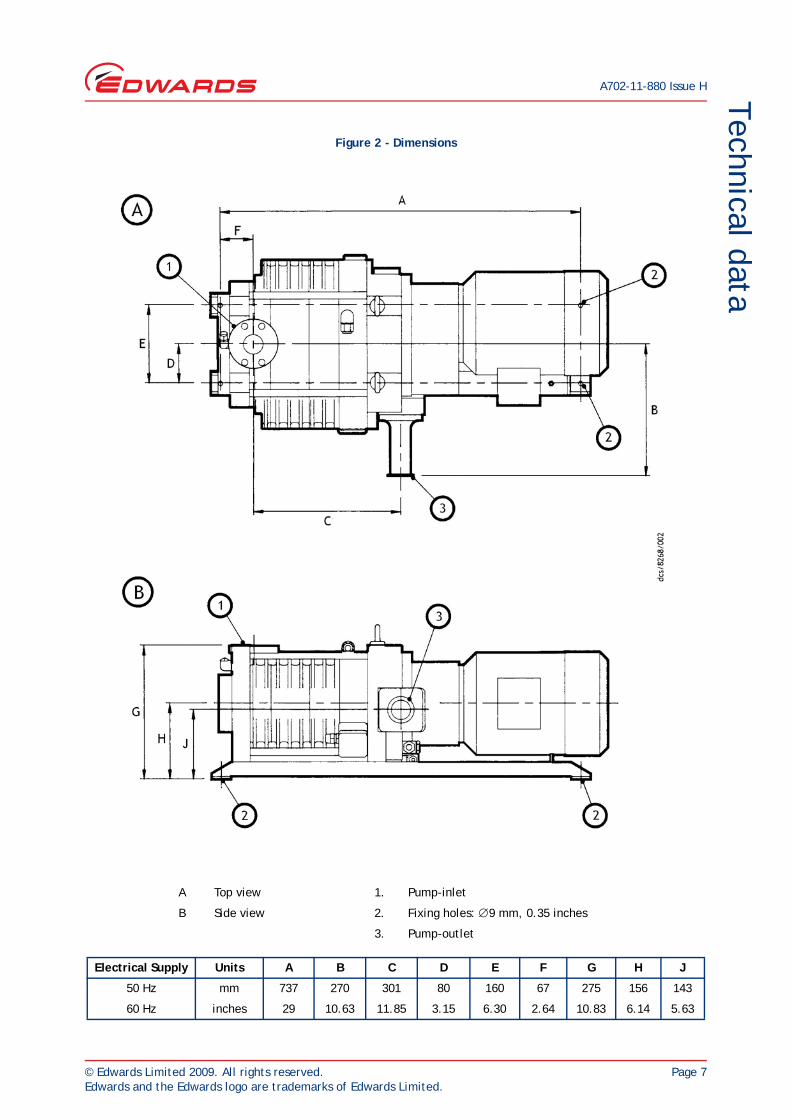
Figure 2 - Dimensions
A Top view 1. Pump-inlet
B Side view 2. Fixing holes: ∅9 mm, 0.35 inches
3. Pump-outlet
Electrical Supply Units A B C D E F G H J
50 Hz mm 737 270 301 80 160 67 275 156 143
60 Hz inches 29 10.63 11.85 3.15 6.30 2.64 10.83 6.14 5.63
A702-11-880 Issue H
Page 8 © Edwards Limited 2009. All rights reserved.Edwards and the Edwards logo are trademarks of Edwards Limited.
Technical data
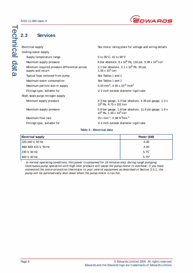
2.3 Services
.
Electrical supply See motor rating plate for voltage and wiring details
Cooling-water supply
Supply temperature range 5 to 35°C, 41 to 95°F
Maximum supply pressure 8 bar absolute, 8 x 10⁵ Pa, 116 psi, 5.99 x 10³ torr
Minimum required pressure differential acrosssupply and return
2.1 bar absolute, 2.1 x 10⁵ Pa, 30 psi,1.55 x 103 torr
Typical heat removed from pump See Tables 1 and 2
Maximum water consumption See Tables 1 and 2
Maximum particle size in supply 0.03 mm2, 4.65 x 10⁻⁵ inch2
Fittings type, suitable for 1/2 inch outside diameter rigid tube
Shaft-seals purge nitrogen supply
Minimum supply pressure 0.3 bar gauge, 1.3 bar absolute, 4.35 psi gauge, 1.3 x 10⁵ Pa, 9.75 x 10² torr
Maximum supply pressure 0.8 bar gauge, 1.8 bar absolute, 11.6 psi gauge, 1.8 x 10⁵ Pa, 1.35 x 10³ torr
Maximum flow rate 25 l.min-1, 0.88 ft3min-1
Fittings type, suitable for 1/4 inch outside diameter rigid tube
Table 3 - Electrical data
Electrical supply Power (kW)
220-240 V, 50 Hz 4.00
380/400/415 V, 50 Hz 4.00
230 V, 60 Hz 5.75*
* In normal operating conditions, this power is consumed for 15 minutes only, during rough pumping. Continuous pump operation with high inlet pressure will cause the pump-motor to overheat; if you have connected the motor-protection thermistor to your control equipment as described in Section 3.5.1, the pump will be automatically shut-down when the pump-motor is too hot.
460 V, 60 Hz 5.75*
© Edwards Limited 2009. All rights reserved. Page 9Edwards and the Edwards logo are trademarks of Edwards Limited.
Technical dataA702-11-880 Issue H
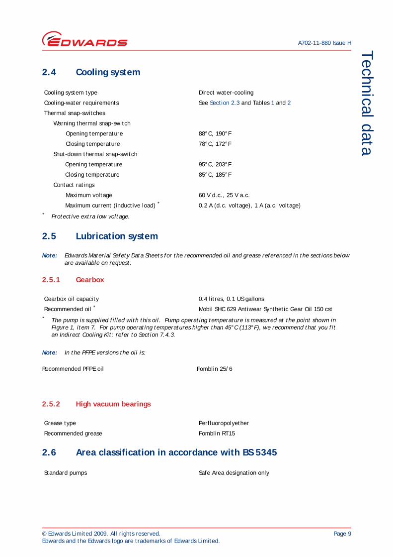
2.4 Cooling system
2.5 Lubrication system
Note: Edwards Material Safety Data Sheets for the recommended oil and grease referenced in the sections below are available on request.
2.5.1 Gearbox
Note: In the PFPE versions the oil is:
2.5.2 High vacuum bearings
2.6 Area classification in accordance with BS 5345
Cooling system type Direct water-cooling
Cooling-water requirements See Section 2.3 and Tables 1 and 2
Thermal snap-switches
Warning thermal snap-switch
Opening temperature 88°C, 190°F
Closing temperature 78°C, 172°F
Shut-down thermal snap-switch
Opening temperature 95°C, 203°F
Closing temperature 85°C, 185°F
Contact ratings
Maximum voltage 60 V d.c., 25 V a.c.
Maximum current (inductive load) *
* Protective extra low voltage.
0.2 A (d.c. voltage), 1 A (a.c. voltage)
Gearbox oil capacity 0.4 litres, 0.1 US gallons
Recommended oil *
* The pump is supplied filled with this oil. Pump operating temperature is measured at the point shown in Figure 1, item 7. For pump operating temperatures higher than 45°C (113°F), we recommend that you fit an Indirect Cooling Kit: refer to Section 7.4.3.
Mobil SHC 629 Antiwear Synthetic Gear Oil 150 cst
Recommended PFPE oil Fomblin 25/6
Grease type Perfluoropolyether
Recommended grease Fomblin RT15
Standard pumps Safe Area designation only

A702-11-880 Issue H
Page 10 © Edwards Limited 2009. All rights reserved.Edwards and the Edwards logo are trademarks of Edwards Limited.
This page has been intentionally left blank.
© Edwards Limited 2009. All rights reserved. Page 11Edwards and the Edwards logo are trademarks of Edwards Limited.
InstallationA702-11-880 Issue H
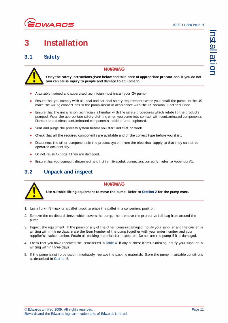
3 Installation3.1 Safety
A suitably trained and supervised technician must install your GV pump.
Ensure that you comply with all local and national safety requirements when you install the pump. In the US, make the wiring connections to the pump-motor in accordance with the US National Electrical Code.
Ensure that the installation technician is familiar with the safety procedures which relate to the products pumped. Wear the appropriate safety-clothing when you come into contact with contaminated components. Dismantle and clean contaminated components inside a fume-cupboard.
Vent and purge the process system before you start installation work.
Check that all the required components are available and of the correct type before you start.
Disconnect the other components in the process system from the electrical supply so that they cannot be operated accidentally.
Do not reuse O-rings if they are damaged.
Ensure that you connect, disconnect and tighten Swagelok connectors correctly: refer to Appendix A1.
3.2 Unpack and inspect
1. Use a fork-lift truck or a pallet truck to place the pallet in a convenient position.
2. Remove the cardboard sleeve which covers the pump, then remove the protective foil bag from around the pump.
3. Inspect the equipment. If the pump or any of the other items is damaged, notify your supplier and the carrier in writing within three days; state the Item Number of the pump together with your order number and your supplier’s invoice number. Retain all packing materials for inspection. Do not use the pump if it is damaged.
4. Check that you have received the items listed in Table 4. If any of these items is missing, notify your supplier in writing within three days.
5. If the pump is not to be used immediately, replace the packing materials. Store the pump in suitable conditions as described in Section 6.
WARNING
Obey the safety instructions given below and take note of appropriate precautions. If you do not, you can cause injury to people and damage to equipment.
WARNING
Use suitable lifting-equipment to move the pump. Refer to Section 2 for the pump mass.
A702-11-880 Issue H
Page 12 © Edwards Limited 2009. All rights reserved.Edwards and the Edwards logo are trademarks of Edwards Limited.
Installation
3.3 Locate the pump
Note: If you want to operate the pump in an environment with an ambient temperature of 0°C (32°F) or lower, contact your supplier or Edwards for advice.
Ensure that the cooling-air flow around the pump-motor is not restricted.
1. Refer to Figure 1. Remove from the fixing-holes (10) the four nuts and bolts which secure the pump frame (9) to the pallet.
2. Attach suitable lifting-equipment to the two lifting bolts (1) to move the pump.
3. Locate the pump on a firm, level surface. Ensure that the surface is clean and free from debris and contamination (such as oil). Use suitable bolts through the four fixing-holes (10) to secure the pump in position.
3.4 Check the gearbox oil-level
Refer to Figure 1. The pump is supplied filled with oil. Before you operate the pump, check that the gearbox oil-level is correct: the oil-level must be between the MIN and MAX marks on the bezel of the oil-level sight-glass (16): see detail B. If necessary, pour more oil into the gearbox: refer to Section 5.3.
3.5 Electrical connections
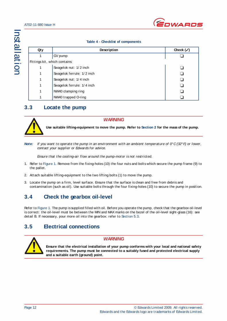
Table 4 - Checklist of components
Qty Description Check ( )
1 GV pump
Fittings kit, which contains:
1 Swagelok nut: 1/2 inch
1 Swagelok ferrule: 1/2 inch
1 Swagelok nut: 1/4 inch
1 Swagelok ferrule: 1/4 inch
1 NW40 clamping ring
1 NW40 trapped O-ring
WARNING
Use suitable lifting-equipment to move the pump. Refer to Section 2 for the mass of the pump.
WARNING
Ensure that the electrical installation of your pump conforms with your local and national safety requirements. The pump must be connected to a suitably fused and protected electrical supply and a suitable earth (ground) point.
© Edwards Limited 2009. All rights reserved. Page 13Edwards and the Edwards logo are trademarks of Edwards Limited.
InstallationA702-11-880 Issue H
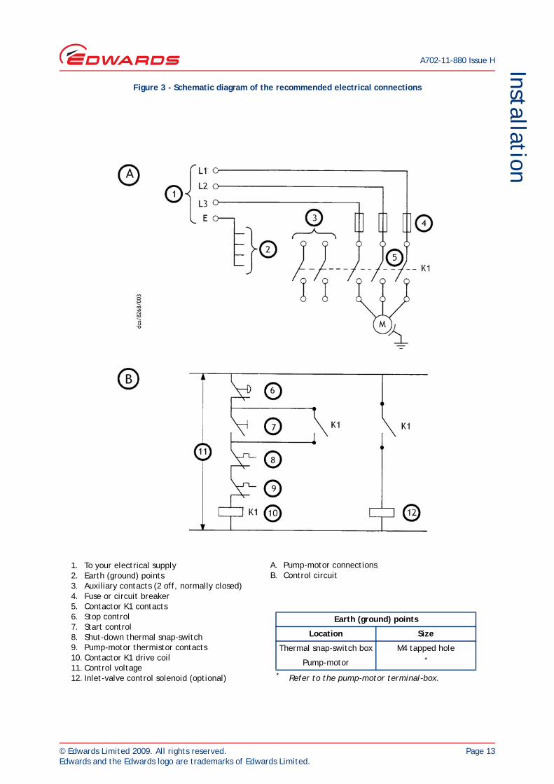
Figure 3 - Schematic diagram of the recommended electrical connections
1. To your electrical supply2. Earth (ground) points3. Auxiliary contacts (2 off, normally closed)4. Fuse or circuit breaker5. Contactor K1 contacts6. Stop control7. Start control8. Shut-down thermal snap-switch9. Pump-motor thermistor contacts10. Contactor K1 drive coil11. Control voltage12. Inlet-valve control solenoid (optional)
A. Pump-motor connectionsB. Control circuit
Earth (ground) points
Location Size
Thermal snap-switch box M4 tapped hole
Pump-motor *
* Refer to the pump-motor terminal-box.
A702-11-880 Issue H
Page 14 © Edwards Limited 2009. All rights reserved.Edwards and the Edwards logo are trademarks of Edwards Limited.
Installation
3.5.1 Introduction
We recommend that you connect the electrical supply to the pump through a suitable starter or circuit breaker which has thermal over-current protection and a thermistor control module which complies with IEC34-11 or BS4999 Part III. You must adjust the over-current protection to suit your installation.
The pump will restart automatically when the electrical supply is restored after it has been interrupted. If you do not want the pump to automatically restart, connect the electrical suppy to the pump-motor through control equipment which must be manually reset after an electrical supply interruption.
Refer to Figure 1. Note that there are earth (ground) points in the pump-motor terminal-box (5) and in the thermal snap-switch box (8).
3.5.2 Connect to the pump-motor terminal-box
CAUTIONEnsure that the pump-motor terminal box is correctly configured for your electrical supply. If the terminal-box is not correctly configured, you can damage the pump-motor when you operate it.
The bottom of the pump-motor terminal-box has a number of cable-entry leadthrough holes, sealed by plugs; you can connect to the terminal-box in one of two ways:
You can use a single 6-core cable to connect the electrical supply to the pump-motor terminals and to connect the outputs of the motor protection thermistor to your control equipment. If you use this option, remove the plug from one of the cable-entry leadthrough holes.
You can use a 4-core cable to connect the electrical supply to the pump-motor terminals, and use a 2-core cable to connect the outputs of the motor protection thermistor to your control equipment. If you use this option, remove the plugs from two of the cable-entry leadthrough holes.
Use the following procedure to make the electrical connections to the pump-motor terminal box:
1. Remove the cover from the pump-motor terminal-box (Figure 1, item 5).
2. Remove the plug (s) from the cable-entry leadthrough hole(s) that you intend to use from the bottom of the terminal-box.
3. Fit suitable cable-gland (s) and nut(s) to the entry hole (s), then pass the cable (s) through the cable-gland (s) and tighten the cable-gland (s). The cable-gland (s) you use must be rated to provide seal protection of IP55 (in IEC 529) or better to the terminal-box.
4. Ensure that the terminal-box is correctly configured for your electrical supply voltage, as indicated by the motor suppliers information. This will be on the rating plate or in the terminal box.
5. Connect the earth (ground) wire in your cable to the earth (ground) terminal (4).
6. Connect the other ends of the phase conductors and the earth (ground) wire to your electrical supply.
7. Connect the two thermistor wires in your cable to the terminals on the thermistor block.
8. Connect the other end of the thermistor wires to your control equipment.
9. Tighten the cable-gland nut (s) strain-relief screws and refit the terminal-box cover.
© Edwards Limited 2009. All rights reserved. Page 15Edwards and the Edwards logo are trademarks of Edwards Limited.
InstallationA702-11-880 Issue H
3.5.3 Connect to the thermal snap-switches
CAUTIONEnsure that you route the thermal snap-switch cable away from hot surfaces of the pump or other equipment. If you do not, the cable may be damaged.
Connect the output of the warning thermal snap-switch to your control equipment to provide an indication that the pump is too hot.
You must connect the output of the shut-down thermal snap-switch to the electrical-overload control-loop of your contactor, so that the contactor will automatically switch off the pump if it is too hot: refer to Figure 3.
The thermal snap-switches will reset (that is, close again) when the pump cools down to a preset temperature (see Section 2). You must therefore ensure that your control equipment incorporates a manual reset device so that the pump does not automatically switch on again when it cools down.
Use the following procedure to connect to the thermal snap-switches. If you connect to the thermal snap-switches as described below, the outputs from the thermal snap-switches will be normally closed and will open when the pump is too hot.
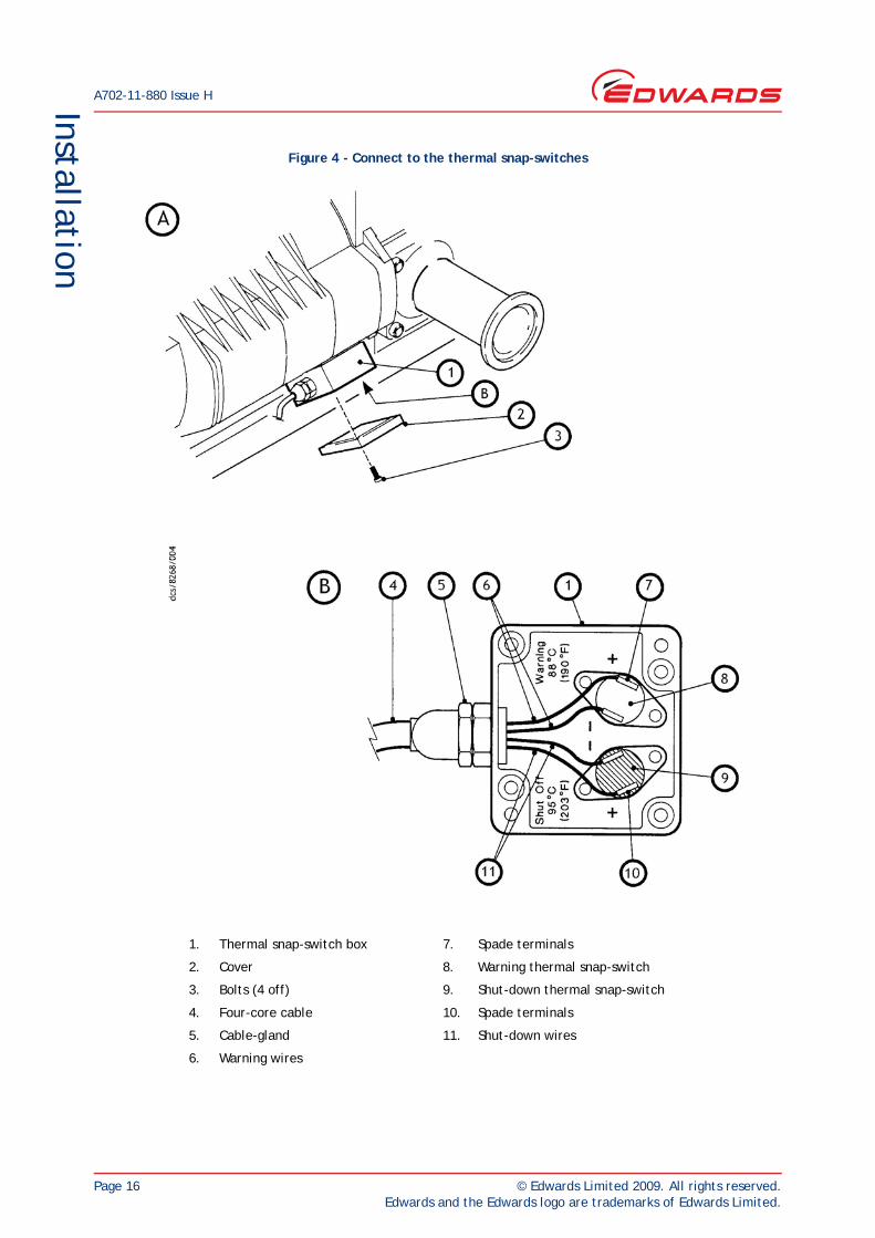
1. Refer to Figure 4. Undo and remove the four screws (3) which secure the cover (2) to the thermal snap-switch box (1), then remove the cover.
2. Remove the plastic bag from inside the box, then open the bag; this bag contains the crimp connectors and insulators you will use to connect to the snap-switches.
3. Pass a suitably rated four-core cable through the cable-gland (5).
4. Fit the crimp connectors to the ends of the four wires in the cable (4), then fit the insulators around the connections.
5. Fit the crimp connectors on one pair of wires (11) to the spade terminals (10) of the shut-down thermal snap-switch (9).
6. Connect the other ends of the same pair of wires to the electrical-overload loop of your contactor.
7. Fit the crimp connectors on the remaining pair of wires (6) to the spade terminals (7) on the warning thermal snap-switch (8).
8. Connect the other ends of the same pairs of wires to the warning circuit of your control equipment.
9. Tighten the cable-gland (5) to secure the cable in position.
10. Refit the cover (2) and secure with the four screws (3).
WARNING
You must connect the shut-down thermal snap-switch so that the pump stops when the thermal snap-switch opens. If you do not, there may be a risk of fire or explosion.
WARNING
Incorporate a manual reset device in your control equipment. If you do not (and a fault which causes the shut-down thermal snap-switch to open is not corrected), the pump will automatically switch on again when it cools down. If you have started maintenance or fault finding on the pump, there will then be a risk of fire or explosion and injury to people.
A702-11-880 Issue H
Page 16 © Edwards Limited 2009. All rights reserved.Edwards and the Edwards logo are trademarks of Edwards Limited.
Installation
Figure 4 - Connect to the thermal snap-switches
1. Thermal snap-switch box 7. Spade terminals
2. Cover 8. Warning thermal snap-switch
3. Bolts (4 off) 9. Shut-down thermal snap-switch
4. Four-core cable 10. Spade terminals
5. Cable-gland 11. Shut-down wires
6. Warning wires
© Edwards Limited 2009. All rights reserved. Page 17Edwards and the Edwards logo are trademarks of Edwards Limited.
InstallationA702-11-880 Issue H
3.6 Check the direction of pump rotation
Note: If you cannot easily see the cooling-fan to determine its direction of rotation, watch the blanking- plate on the pump inlet; if the blanking-plate lifts from the inlet when you switch on the pump, the direction of rotation is incorrect.
1. Refer to Figure 1. Loosen the bolts which secure the blanking-plate to the pump-inlet (11), so that the blanking-plate is free to move, but so that it cannot come off of the inlet. Remove the blanking-cap from the pump outlet (6).
2. Watch the cooling-fan (4), switch on the pump for one or two seconds, then switch the pump off.
3. If the cooling-fan does not rotate in the correct direction shown by the arrow (3) on the pump-motor, the direction of rotation is incorrect. If the direction of rotation is incorrect:
Isolate the pump from the electrical supply.
Reverse any two of the electrical supply phase-wires in the pump-motor terminal-box: refer to Section 3.5.
Repeat Steps 2 and 3 to ensure that the direction of rotation is now correct.
3.7 Fit a mechanical booster pump (optional)
If you want to use a mechanical booster pump with the GV pump, fit it now. Details of the connection kits available from Edwards are given in Section 7.4.2. Refer to the installation procedures in the instruction manual supplied with the connection kit.
3.8 Connect the cooling-water supply
Note: The following procedure assumes that you use the GV pump with direct cooling, as supplied. If you want to use indirect cooling on the GV pump, install an Indirect Cooling Kit (see Section 7.4.3) and connect to the cooling-water supply as described in the instruction manual supplied with the Kit.
Take note of the following when you connect the cooling-water supply and return pipelines:
If you need to connect more than one GV pump to the water supply, you must connect them in parallel and not in series.
We recommend that you incorporate a suitable ball-type flow indicator in your water return pipeline, to provide a visual indication of cooling-water flow through the GV pump.
We recommend that you incorporate a suitable filter in the water supply pipeline, if the water supply contains particulates.
To prevent damage to the pump in the event of cooling-water supply failure or a blockage in the pump, we recommend that you incorporate a suitable flow-switch in the cooling-water return pipelines; you can connect the outputs of the flow-switch to your control equipment to shut down the pump when the cooling-water flow through the pump is too low.
WARNING
You must ensure that the direction of rotation of the pump is correct before you operate the pump. If you do not, and the pump direction of rotation is incorrect, the inlet pipeline will be pressurised and may be damaged and there will be a risk of injury to people or explosion or fire.
A702-11-880 Issue H
Page 18 © Edwards Limited 2009. All rights reserved.Edwards and the Edwards logo are trademarks of Edwards Limited.
Installation
Connect the cooling-water supply as described below; you must use 1/2 inch outside diameter pipes for the cooling-water supply and return pipelines.
1. Refer to Figure 1. Remove the red blanking-plug from the cooling-water inlet (17) and remove the red blanking-cap from the cooling-water outlet (12).
2. Remove the 1/2 inch Swagelok compression nut and ferrule from the fittings kit and fit finger-tight onto the cooling-water outlet (12).
3. Fit the end of your cooling-water return pipeline to the Swagelok compression fitting on the cooling-water outlet (12), then tighten the Swagelok compression nut to secure the pipeline in place.
4. Fit the end of your cooling-water supply pipeline to the Swagelok compression fitting on the cooling-water inlet (17), then tighten the Swagelok compression nut to secure the pipeline in place.
3.9 Connect the shaft-seals purge and gas-ballast gas supplies
3.9.1 Introduction
You must determine the correct shaft-seals purge and gas-ballast requirements for your application. You must connect nitrogen supplies to the gas systems if you want to pump dangerous gases.
If nitrogen shaft-seals purge and gas-ballast is not required for your application, use the procedure in Section 3.9.2 to connect a compressed air supply to the shaft-seals purge inlet. As supplied, the gas-ballast system can deliver filtered atmospheric air to the pump gas-ballast inlet, so you do not need to connect an air supply to the gas-ballast system.
If required for your application, connect nitrogen supplies to the shaft-seals inlet and to the gas-ballast system. Use the procedures in Sections 3.9.2 and 3.9.3 to connect nitrogen supplies to the shaft-seals purge inlet and to the gas-ballast system.
3.9.2 Connect the shaft-seals purge air or nitrogen supply
CAUTIONYour compressed air or nitrogen supply pressure must comply with the requirements of Section 2.3. If it does not, the shaft-seals purge pipeline may become over-pressurised and the shaft-seals may fail.
Note: Your compressed air or nitrogen gas supply must be clean and dry.
We recommend that you install suitable pressure control devices, a pressure gauge, and an automatically operated isolation-valve in your compressed air or nitrogen supply configured so that:
The shaft-seals purge air or nitrogen supply is on whenever the pump is on.
If you connect a nitrogen supply, the nitrogen supply is off whenever the pump is off.
Whenever the shaft-seals purge air or nitrogen supply is on, you must maintain the pressure to the shaft-seals as specified in Section 2.3.
WARNING
If you want to pump dangerous gases, fit a suitable closed-circuit nitrogen supply to the shaft-seals purge inlet, to prevent the escape of dangerous gases from the pump.
© Edwards Limited 2009. All rights reserved. Page 19Edwards and the Edwards logo are trademarks of Edwards Limited.
InstallationA702-11-880 Issue H
Use the following procedure to connect your shaft-seals purge air or nitrogen supply; you must use a rigid metal (such as stainless steel) pipeline with an outside diameter of 1/4 inch for your air or nitrogen supply pipeline.
1. Refer to Figure 1. Remove the blue blanking cap from the shaft-seals purge inlet (18).
2. Remove the 1/4 inch Swagelok nut and ferrule from the fittings kit and fit finger-tight onto the shaft-seals purge inlet connection (18).
3. Fit the end of your air or nitrogen supply pipeline to the shaft-seals purge inlet connection (18), then tighten the Swagelok compression nut to secure the pipeline in place: refer to Appendix A1.
3.9.3 Connect a nitrogen gas-ballast supply (optional)
Note: Ensure that the gas-ballast nitrogen supply is clean and dry.
Your nitrogen supply pipeline must terminate in a 1/4 inch BSP female fitting, to enable you to connect it to the gas ballast inlet.
If required for your application, you can connect a non-venting (to atmosphere) nitrogen gas-ballast supply to the pump. You must connect a non-venting (to atmosphere) nitrogen gas-ballast supply to the pump if you want to pump dangerous gases.
When you connect a nitrogen supply to the gas-ballast system, we recommend that you incorporate a suitable pressure gauge in the nitrogen supply pipeline.
Use the following procedure to connect a nitrogen supply to the gas-ballast system:
1. Refer to Figure 1. Remove the air filter (15) from the gas-ballast inlet (14).
2. Use suitable fittings to connect your nitrogen supply pipeline to the gas-ballast inlet (14).
WARNING
If you want to pump dangerous gases, fit a suitable non-venting (to atmosphere) nitrogen supply to the gas-ballast system, to prevent the escape of dangerous gases from the pump.
A702-11-880 Issue H
Page 20 © Edwards Limited 2009. All rights reserved.Edwards and the Edwards logo are trademarks of Edwards Limited.
Installation
3.10 Connect the pump-inlet and pump-outlet
3.10.1 Connect the pump to your process system
When you connect the pump to the process system:
Support process pipelines to stop the transmission of stress to pipeline joints.
Use a flexible connection in the pipeline from the process system to the pump to reduce vibration and stress in the system pipelines.
You must be able to isolate the pump from the atmosphere and from your process system if you have pumped or produced dangerous chemicals.
On very dusty applications, incorporate an inlet filter in the inlet pipeline, to minimise the ingress of dust into the pump.
To get the best pumping speed, ensure that the pipeline which connects the process system to the pump is as short as possible and has an internal diameter not less than the pump-inlet.
Do not allow debris to get into the pump during installation. Ensure that debris (such as weld slag) cannot get into the pump during operation.
If necessary, contact Edwards or your supplier for advice on inlet isolation-valves, outlet check-valves or other components suitable for your application and system design.
Use the following procedure to connect the inlet of the GV pump to your process system. This procedure assumes that a mechanical booster pump has not been fitted. If a mechanical booster pump has been fitted, use the instructions given in the appropriate instruction manual supplied with the mechanical booster pump.
1. Refer to Figure 1. Undo and remove the bolts which secure the blanking-plate to the pump-inlet (11) and remove the blanking-plate. Retain the bolts.
2. Use the trapped O-ring (fitted to the pump-inlet) to connect the pump-inlet (11) to your vacuum system; secure with the bolts retained in Step 1.
WARNING
Take all necessary safety precautions when you pump toxic, flammable or explosive gases. If you do not, there will be a danger of injury or death to people.
WARNING
Ensure that your system can provide adequate gas-ballast and/or inlet purge to dilute toxic, flammable or explosive gases to safe limits. If you do not, there will be a risk of emission of hazardous gases.
WARNING
When the pump is switched off, gas will flow in reverse direction through the pump and there will be a rapid pressure rise in the inlet pipeline and your process system. If this will cause a dangerous situation (or if it will adversely affect your process), you must incorporate suitable devices (such as a fast-acting inlet isolation-valve or an outlet check-valve) in your system pipelines.
© Edwards Limited 2009. All rights reserved. Page 21Edwards and the Edwards logo are trademarks of Edwards Limited.
InstallationA702-11-880 Issue H
3.10.2 Connect the pump-outlet
CAUTIONInstall an outlet catchpot to prevent the drainage of condensate back into the pump. If you do not, condensate which drains back into the pump may damage it or cause it to seize.
Your exhaust pipeline system must be designed so that the pressure in the pipeline during pump operation is less than 1.3 bar absolute (1.3 x 10⁵ Pa, 975 torr). If the pressure in the pipeline is higher than this pressure, the pump will operate at a high temperature and may trip because of excessive electrical current consumption.
Incorporate flexible bellows in the exhaust pipeline to reduce the transmission of vibration and to prevent loading of coupling-joints. If you use flexible bellows, you must ensure that you use bellows which have a maximum pressure rating which is greater than the highest pressure that can be generated in your system, and which can withstand the maximum temperatures that can be generated by your process conditions.
Use the following procedure to connect the pump-outlet to your exhaust pipeline:
1. Refer to Figure 1. Remove the blanking-cap from the pump-outlet (6).
2. Use the NW40 clamping ring and trapped O-ring supplied in the fittings kit to connect the pump-outlet (6) to your exhaust pipeline.
3.11 Leak test the installation
Leak-test the system after installation and seal any leaks found. Substances which leak from the system may be dangerous to people and there may be a danger of explosion if air leaks into the system.
When supplied, the leak rate of the pump is tested to be less than 1 x 10⁻³ mbar.ls-1 (1 x 10⁻¹ Pa.ls-1, 2.1 x 10⁻⁶ atm.ft3.min-1). The required leak rate for your system will depend on your safety and process requirements.
WARNING
Pipe the exhaust to a suitable treatment plant to prevent the discharge of dangerous gases or vapours to the surrounding atmosphere.
WARNING
Incorporate safety devices to prevent operation of the pump when the exhaust pipeline is restricted or blocked. If you do not, the exhaust pipeline may become over-pressurised and may burst.
WARNING
Leak-test the system after installation and maintenance and seal any leaks found to prevent the leakage of dangerous substances out of the system and leakage of air into the system.
A702-11-880 Issue H
Page 22 © Edwards Limited 2009. All rights reserved.Edwards and the Edwards logo are trademarks of Edwards Limited.
Installation
3.12 Commission the pump
Note: To check the operating temperature of the pump, measure the temperature of the pump at the point shown in Figure 1, item 7.
1. Isolate the pump from your process system.
2. Ensure that the gas-ballast flow valve (Figure 1, item 13) is closed.
3. Turn on the cooling-water supply, the shaft-seals purge air or nitrogen supply, the gas-ballast nitrogen supply (if fitted) and your exhaust-extraction system. Ensure that the pressures and flow rates are as specified in Section 2.3.
4. Check that there are no leaks in the water, air, nitrogen (if fitted) and exhaust-extraction system connections. Seal any leaks found.
5. Switch on the pump.
6. Check that the pressure shown on your shaft-seals purge air or nitrogen pressure gauge is as specified in Section 2.3. If necessary, adjust the pressure of the air or nitrogen supply.
7. Leave the pump to operate for approximately 15 minutes to allow the pump operating temperature to stabilise.
8. Check that the pump operating temperature is in the range 30 to 45°C (86 to 113°F); if the pump operating temperature is outside this range, refer to Section 5.12.
9. Turn off the pump, the cooling-water supply, the shaft-seals air or nitrogen purge supply and the gas-ballast nitrogen supply (if fitted).
© Edwards Limited 2009. All rights reserved. Page 23Edwards and the Edwards logo are trademarks of Edwards Limited.
Operation
A702-11-880 Issue H
4 Operation
The procedures in the following sections assume that you have a pump-inlet isolation-valve fitted to your pump.
4.1 Start the pump
CAUTIONAllow the pump to warm up and use full gas-ballast and inlet purge (if fitted) before you pump condensable vapours. If you do not, the vapours may condense in the pump and corrode or damage the pump.
Use the procedure below to start the pump.
1. Check the gearbox oil-level in the sight-glass on the side of the pump: refer to Section 3.4.
2. Turn on your cooling-water supply, then bleed the trapped air from the water jacket:
Remove the air bleed plug (Figure 1, item 20).
When the water level reaches the top of the plug hole, refit the air bleed plug.
3. Turn on the shaft-seals purge air or nitrogen supply, gas-ballast nitrogen supply (if fitted) and exhaust-extraction system (if fitted).
4. Switch on the pump.
5. Continue at Section 4.2 to check the purge pressures and flows
WARNING
During operation, some parts of the pump become hot; these areas are identified by ‘hot surface’ labels (see Section 1.1). Do not touch these areas of the pump and avoid accidental contact between these areas of the pump and electrical cables and wires, and so forth.
WARNING
Do not operate the pump with the pump-inlet or pump-outlet open to atmosphere. If you do, there will be a danger of injury or death from the rotating mechanisms, from the exposure to vacuum, or from hot exhaust gases.
A702-11-880 Issue H
Page 24 © Edwards Limited 2009. All rights reserved.Edwards and the Edwards logo are trademarks of Edwards Limited.
Operation
4.2 Check the purge pressures and flows
Do the following checks immediately after pump start and regularly during pump operation:
Check that the pressure of your shaft-seals purge air or nitrogen supply is correct and adjust if necessary (refer to Section 2.3).
If fitted, check that the pressure of your gas-ballast nitrogen supply is correct and adjust if necessary.
If necessary, adjust the gas-ballast flow valve (Figure 1, item 13) to achieve the required gas-ballast flow into the pump:
Turn the adjuster knob clockwise to reduce the gas-ballast flow; turn the knob fully clockwise to switch off gas-ballast flow.
Turn the adjuster knob anticlockwise to increase the gas-ballast flow.
4.3 Shut down the pump
CAUTIONPurge the pump before you shut it down. If you do not, process vapours may condense in the pump and corrode or damage it.
Note: If you want to shut down the pump for a long time in an environment where the temperature is close to freezing, we recommend that you drain the cooling-water from the pump to prevent damage to the pump: refer to Section 6.1.
1. Isolate the pump-inlet from the process gases.
2. Refer to Figure 1. Purge the pump of contaminants: operate the pump with full gas-ballast (that is, with the gas-ballast flow valve (13) open) for at least 15 minutes. Alternatively, use one of the following methods:
Operate the pump at or close to atmospheric pressure for at least 15 minutes; this is the recommended method for dusty processes.
Operate the pump with full inlet purge (if fitted) for at least 15 minutes.
3. Close the gas-ballast flow valve (10), or switch off inlet purge (if fitted).
4. Switch off the pump.
5. When the pump has cooled down, turn off the cooling-water supply.
6. Switch off the shaft-seals purge nitrogen supply (if fitted).
WARNING
Ensure that you do not touch the pump-body when you adjust the gas-ballast flow valve. During operation, parts of the pump can become hot.
© Edwards Limited 2009. All rights reserved. Page 25Edwards and the Edwards logo are trademarks of Edwards Limited.
Maintenance
A702-11-880 Issue H
5 Maintenance5.1 Safety
A suitably trained and supervised technician must maintain the pump.
Ensure that the maintenance technician is familiar with the safety procedures which relate to the synthetic oils and greases used and the products pumped. Wear the appropriate safety-clothing when you come into contact with contaminated components, grease and pump oil. Dismantle and clean contaminated components inside a fume-cupboard.
Use suitable lifting equipment and wear safety shoes when you replace the pump-motor or the pump module.
Allow the pump to cool to a safe temperature before you start maintenance work.
Isolate the pump and other components in the process system from the electrical supply so that they can not be operated accidentally.
Recheck the pump rotation direction if the electrical supply has been disconnected.
Do not reuse O-rings or gaskets if they are damaged.
Protect sealing-faces from damage.
Do not touch or inhale the thermal breakdown products of fluorinated materials which may be present if the pump has overheated to 260°C (500°F) and above. These breakdown products are very dangerous. The pump may have overheated if it was misused, if it malfunctioned, or if it was in a fire. Edwards Material Safety Data Sheets for the fluorinated materials used in the pump are available on request: contact your supplier or Edwards.
Leak-test the system after installation work is complete and seal any leaks found to prevent leakage of dangerous substances out of the system and leakage of air into the system: refer to Section 3.11.
5.2 Maintenance plan
The plan in Table 5 details the maintenance operations we recommend to maintain the pump in normal operation. Instructions for each operation are given in the section shown. In practice, the frequency of maintenance is dependent on your process. In clean processes, you may be able to decrease the frequency of maintenance operations; in harsh processes you may have to increase the frequency of maintenance operations. Adjust the maintenance plan according to your experience.
WARNING
Obey the safety instructions given below and take note of appropriate precautions. If you do not, you can cause injury to people and damage to equipment.
A702-11-880 Issue H
Page 26 © Edwards Limited 2009. All rights reserved.Edwards and the Edwards logo are trademarks of Edwards Limited.
Maintenance
5.3 Check the gearbox oil-level and fill the gearbox with oil (if necessary)
Note: If you need to pour oil into the gearbox frequently, or if there is a sudden loss of a large amount of oil, the pump may be faulty: shut down the pump and contact your supplier or Edwards.
Refer to Figure 1 which shows the location of the oil-level sight-glass on the pump. Check that the pump gearbox oil-level is at the MAX mark on the bezel of the oil-level sight-glass (16): see detail C. If the oil-level is below the MAX mark:
1. Refer to Figure 5. Remove the oil filler-plug (1) and O-ring (2) from the oil-filler port (3), fit a suitable funnel to the oil-filler port, then pour the oil through the funnel into the pump gearbox until the oil-level is at the MAX mark on the bezel of the oil-level sight-glass (see Figure 1, detail B). We recommend that you use the oil type specified in Section 2.5.1.
2. If you overfill the gearbox, use a suitable pump or syringe to suck oil out of the gearbox; when the oil level reaches the MAX mark on the sight-glass (see Figure 1, detail B), refit and tighten the oil drain-plug and O-ring (11); continue at Step 1 again, to check that the oil-level is now correct.
3. Refit the oil filler-plug (1) and O-ring (2) to the oil-filler port (3) and tighten.
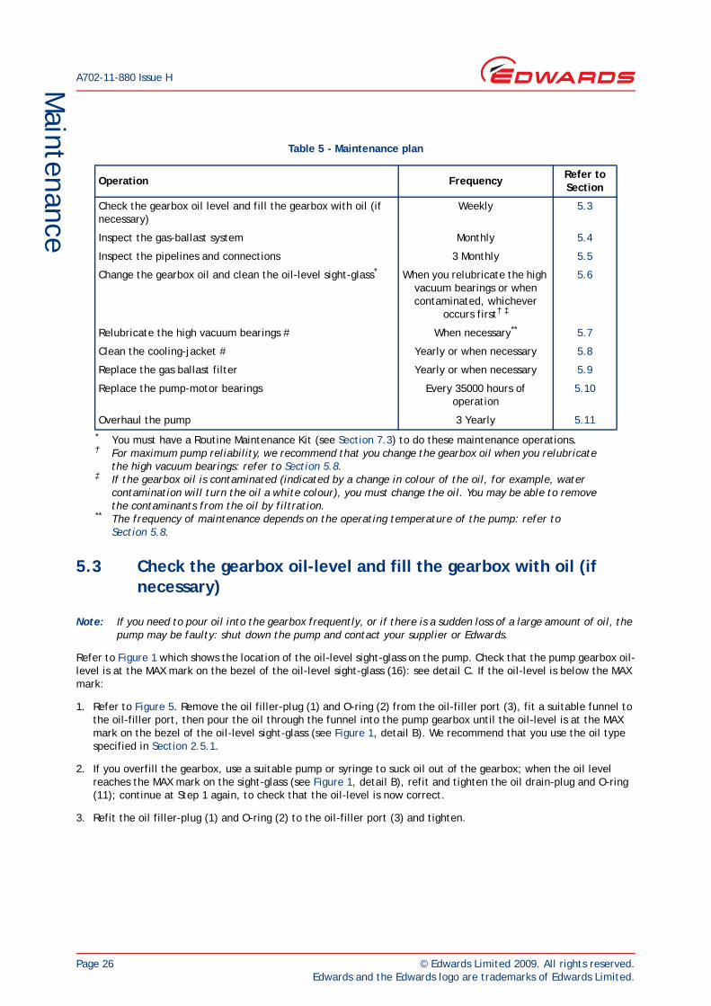
Table 5 - Maintenance plan
Operation Frequency Refer to Section
Check the gearbox oil level and fill the gearbox with oil (if necessary)
Weekly 5.3
Inspect the gas-ballast system Monthly 5.4
Inspect the pipelines and connections 3 Monthly 5.5
Change the gearbox oil and clean the oil-level sight-glass*
* You must have a Routine Maintenance Kit (see Section 7.3) to do these maintenance operations.
When you relubricate the high vacuum bearings or when contaminated, whichever
occurs first† ‡
† For maximum pump reliability, we recommend that you change the gearbox oil when you relubricate the high vacuum bearings: refer to Section 5.8.
‡ If the gearbox oil is contaminated (indicated by a change in colour of the oil, for example, water contamination will turn the oil a white colour), you must change the oil. You may be able to remove the contaminants from the oil by filtration.
5.6
Relubricate the high vacuum bearings # When necessary**
** The frequency of maintenance depends on the operating temperature of the pump: refer to Section 5.8.
5.7
Clean the cooling-jacket # Yearly or when necessary 5.8
Replace the gas ballast filter Yearly or when necessary 5.9
Replace the pump-motor bearings Every 35000 hours of operation
5.10
Overhaul the pump 3 Yearly 5.11
© Edwards Limited 2009. All rights reserved. Page 27Edwards and the Edwards logo are trademarks of Edwards Limited.
Maintenance
A702-11-880 Issue H
5.4 Inspect the gas-ballast system
Use the following procedure to inspect the gas-ballast system. Note that if you have not connected a nitrogen gas-ballast supply, you must replace the gas-ballast air filter every year (see Section 5.9). However, you may need to replace the air filter more frequently if you use the GV pump in an environment where there are excessive air-borne particulates; refer to Section 7.3 for the Item Number for the routine maintenance kit, which contains a replacement air filter.
1. Refer to Figure 1. If you have connected a nitrogen gas-ballast supply, continue at Step 5, otherwise continue at Step 2 to inspect the air filter.
2. Inspect the air filter (15); if there are excessive deposits lodged in the air filter, continue at Step 3, otherwise continue at Step 5.
3. Remove the air filter (15) from the gas-ballast inlet (14); dispose of the air filter.
4. Fit a new air filter (15) to the gas-ballast inlet (14).
5. Inspect all of the clamps in the gas-ballast system and check that they are secure: tighten any loose connections.
5.5 Inspect the pipelines and connections
1. Inspect all cooling-water pipelines and connections; check that they are not corroded or damaged. Replace any of the pipelines and connections that are corroded or damaged. Check that all cooling-water connections are secure. Tighten any connections that are loose.
2. Inspect all air or nitrogen supply pipelines and connections; check that they are not corroded or damaged. Replace any pipelines and connections that are corroded or damaged. Check that all air or nitrogen supply connections are secure. Tighten any connections that are loose.
3. Inspect all electrical cables; check that they are not damaged and have not overheated. Replace any cables that are damaged or have overheated. Check that all electrical connections are secure. Tighten any connections that are loose.
4. Inspect all process and exhaust pipelines; check that they are not corroded or damaged. Replace any pipelines that are corroded or damaged. Check that all process and exhaust connections are secure. Tighten any connections that are loose.
A702-11-880 Issue H
Page 28 © Edwards Limited 2009. All rights reserved.Edwards and the Edwards logo are trademarks of Edwards Limited.
Maintenance
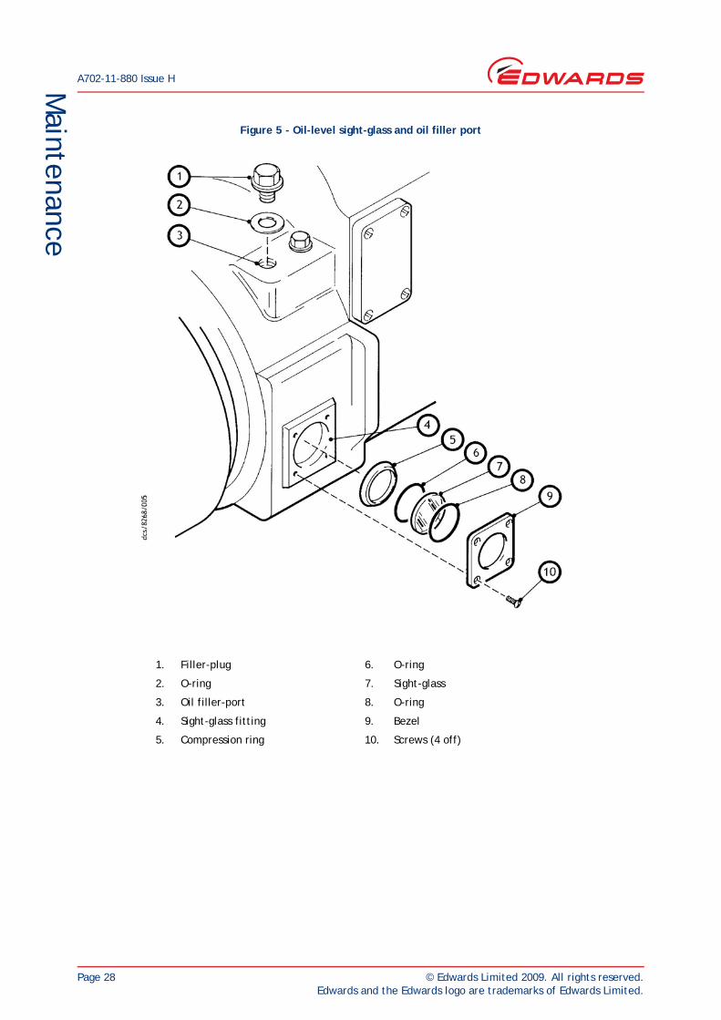
Figure 5 - Oil-level sight-glass and oil filler port
1. Filler-plug 6. O-ring
2. O-ring 7. Sight-glass
3. Oil filler-port 8. O-ring
4. Sight-glass fitting 9. Bezel
5. Compression ring 10. Screws (4 off)
© Edwards Limited 2009. All rights reserved. Page 29Edwards and the Edwards logo are trademarks of Edwards Limited.
Maintenance
A702-11-880 Issue H
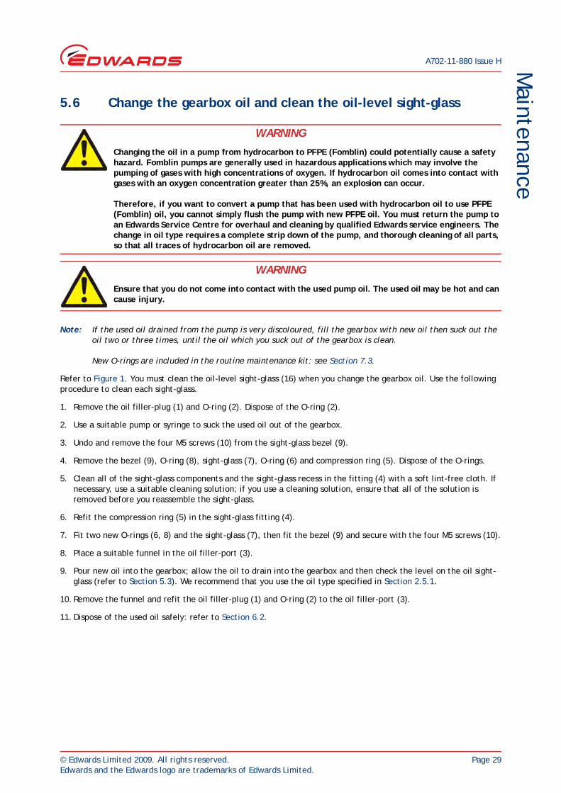
5.6 Change the gearbox oil and clean the oil-level sight-glass
Note: If the used oil drained from the pump is very discoloured, fill the gearbox with new oil then suck out the oil two or three times, until the oil which you suck out of the gearbox is clean.
New O-rings are included in the routine maintenance kit: see Section 7.3.
Refer to Figure 1. You must clean the oil-level sight-glass (16) when you change the gearbox oil. Use the following procedure to clean each sight-glass.
1. Remove the oil filler-plug (1) and O-ring (2). Dispose of the O-ring (2).
2. Use a suitable pump or syringe to suck the used oil out of the gearbox.
3. Undo and remove the four M5 screws (10) from the sight-glass bezel (9).
4. Remove the bezel (9), O-ring (8), sight-glass (7), O-ring (6) and compression ring (5). Dispose of the O-rings.
5. Clean all of the sight-glass components and the sight-glass recess in the fitting (4) with a soft lint-free cloth. If necessary, use a suitable cleaning solution; if you use a cleaning solution, ensure that all of the solution is removed before you reassemble the sight-glass.
6. Refit the compression ring (5) in the sight-glass fitting (4).
7. Fit two new O-rings (6, 8) and the sight-glass (7), then fit the bezel (9) and secure with the four M5 screws (10).
8. Place a suitable funnel in the oil filler-port (3).
9. Pour new oil into the gearbox; allow the oil to drain into the gearbox and then check the level on the oil sight-glass (refer to Section 5.3). We recommend that you use the oil type specified in Section 2.5.1.
10. Remove the funnel and refit the oil filler-plug (1) and O-ring (2) to the oil filler-port (3).
11. Dispose of the used oil safely: refer to Section 6.2.
WARNING
Changing the oil in a pump from hydrocarbon to PFPE (Fomblin) could potentially cause a safety hazard. Fomblin pumps are generally used in hazardous applications which may involve the pumping of gases with high concentrations of oxygen. If hydrocarbon oil comes into contact with gases with an oxygen concentration greater than 25%, an explosion can occur.
Therefore, if you want to convert a pump that has been used with hydrocarbon oil to use PFPE (Fomblin) oil, you cannot simply flush the pump with new PFPE oil. You must return the pump to an Edwards Service Centre for overhaul and cleaning by qualified Edwards service engineers. The change in oil type requires a complete strip down of the pump, and thorough cleaning of all parts, so that all traces of hydrocarbon oil are removed.
WARNING
Ensure that you do not come into contact with the used pump oil. The used oil may be hot and can cause injury.
A702-11-880 Issue H
Page 30 © Edwards Limited 2009. All rights reserved.Edwards and the Edwards logo are trademarks of Edwards Limited.
Maintenance
5.7 Relubricate the high vacuum bearings
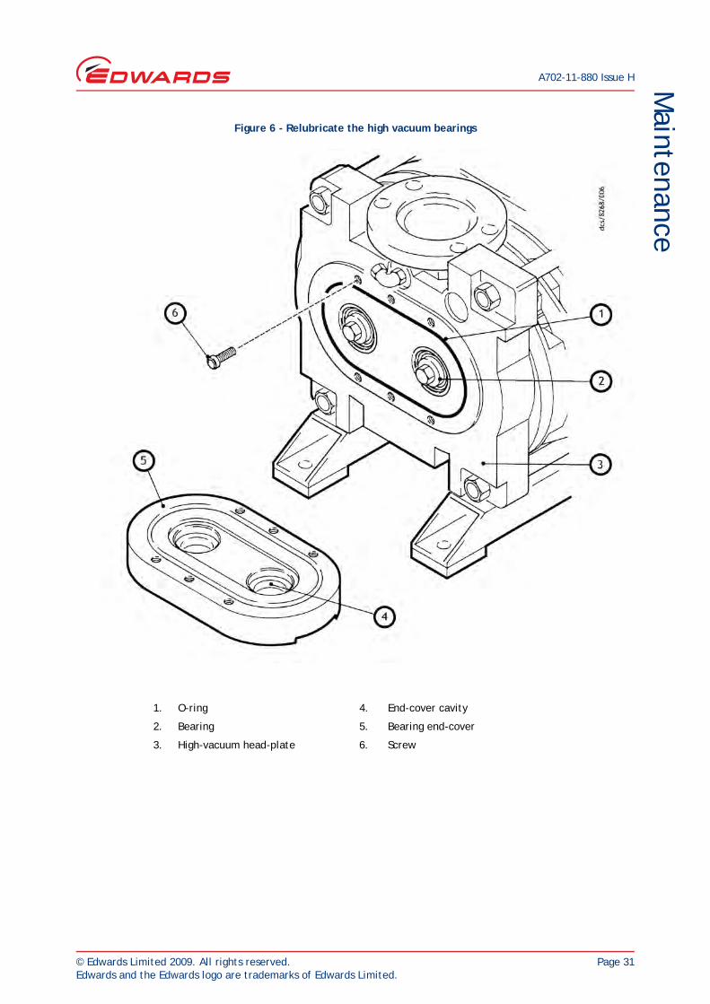
1. Refer to Figure 6. Undo and remove the six screws (6) which secure the bearing end-cover (5) to the high-vacuum head-plate (3).
2. Lift away the end-cover (5) and remove the O-ring (1). Dispose of the O-ring.
3. Use a clean lint-free cloth or a plastic or wooden spatula to remove as much old grease as possible from the end-cover (5) and bearings (2). Do not use your fingers for this operation.
4. Inspect the bearings (2) for obvious signs of wear or the presence of debris. If the bearings are worn, return the pump to an Edwards Service Centre for repair.
5. If the bearings are in a satisfactory condition, force new PFPE grease (supplied in the maintenance kit) into the bearings so that a smooth layer of grease covers the case and bearings: do not put grease into the bearing end-cover (5), and do not over-pack the bearings or the pump will run hot.
6. Apply a light wipe of PFPE grease to the new O-ring (1) and position the O-ring in its groove in the head-plate (3).
7. Refit the bearing end-cover (5) to the head-plate (3) and secure with the six screws (6).
© Edwards Limited 2009. All rights reserved. Page 31Edwards and the Edwards logo are trademarks of Edwards Limited.
Maintenance
A702-11-880 Issue H
Figure 6 - Relubricate the high vacuum bearings
1. O-ring 4. End-cover cavity
2. Bearing 5. Bearing end-cover
3. High-vacuum head-plate 6. Screw
A702-11-880 Issue H
Page 32 © Edwards Limited 2009. All rights reserved.Edwards and the Edwards logo are trademarks of Edwards Limited.
Maintenance
5.8 Flush the cooling jacket
Flush the cooling jacket every year or when you think that the cooling efficiency is reduced because of deposits or other contamination in the cooling jacket. The pressure and flow rate of the water supply that you use to flush the cooling jacket must be equal to or higher than the normal cooling-water supply. Do not exceed the pressure specified in Section 2.3.
1. Switch off your cooling-water supply.
2. Refer to Figure 1. Disconnect the cooling-water supply and return pipelines from the water inlet (17) and outlet (12).
3. Fit a suitable water supply pipeline to the water outlet connection (12), and fit a suitable water return pipeline to the water inlet connection (17).
4. Turn on the water supply to flush the cooling jacket in the reverse direction, and wash out any deposits from the cooling jacket.
5. Allow the water to flow for a few minutes, switch off the water supply, then disconnect the water return pipeline.
6. Place a suitable splash tray under the cooling-water inlet connection (17), then unscrew and remove the 3/8 inch BSP water inlet fitting (that is, the fitting to which the cooling-water inlet connection is fitted).
7. Use a suitable tool to remove any sediments from the port.
8. Turn on the water supply for a short time to flush any remaining deposits from the cooling-jacket.
9. Disconnect the water supply pipeline from the cooling-water outlet connection (12), then dispose of the water and deposits in the splash tray.
10. Apply a suitable thread sealant (such as Loctite 577) to the threads of the 3/8 inch BSP water inlet fitting, then refit the fitting to the port in the end of the pump.
11. Refit your pump cooling-water supply and return pipelines to the water inlet (17) and outlet (12) connections.
5.9 Replace the gas ballast filter
1. Refer to Figure 1. Unscrew and remove the air filter (15) from the gas-ballast inlet (14); dispose of the air filter.
2. Fit a new air filter (15) to the gas-ballast inlet (14); refer to Section 7.3 for the Item Number for the routine maintenance kit, which contains a replacement air filter.
WARNING
If the water flow through the cooling jacket is blocked or restricted, the water in the pump may get very hot. Allow the pump to cool down before you remove the cooling-water connections. If you do not, hot water may be ejected from the pump and may cause injury.
© Edwards Limited 2009. All rights reserved. Page 33Edwards and the Edwards logo are trademarks of Edwards Limited.
Maintenance
A702-11-880 Issue H
5.10 Replace the pump-motor bearings
You must only replace the pump-motor bearings if you have been suitably trained in all of the procedures required to remove and refit the motor, to dismantle and reassemble the motor, and to replace the motor bearings.
When you replace the pump-motor bearings:
You will need a Motor bearing kit (see Section 7.3).
Only use approved procedures to remove and refit the pump-motor, to dismantle and reassemble the pump-motor, and to replace the pump-motor bearings.
You must lightly lubricate the new bearings with a suitable grease, such as:
BP LC2 Energrease
Esso N2 Unirex
Castrol LMX
Mobil HP Mobilgrease.
To drive the bearings onto the rotor shaft, use a short length of suitable tube or a suitable drift to apply pressure only to the inner races of the bearings.
5.11 Overhaul the pump
We recommend that the pump is given a major overhaul every three years. Such an overhaul is outside the scope of this manual and should be done by qualified Edwards service personnel: contact your supplier or Edwards.
WARNING
Do not replace the pump-motor bearings unless you have been suitably trained in the necessary procedures. If you are not suitably trained, you may damage the motor and it may not operate correctly or safely.
A702-11-880 Issue H
Page 34 © Edwards Limited 2009. All rights reserved.Edwards and the Edwards logo are trademarks of Edwards Limited.
Maintenance
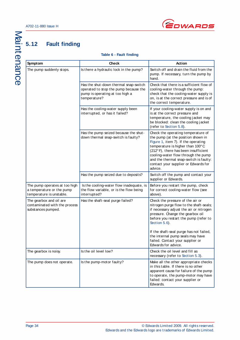
5.12 Fault finding
Table 6 - Fault finding
Symptom Check Action
The pump suddenly stops. Is there a hydraulic lock in the pump? Switch off and drain the fluid from the pump. If necessary, turn the pump by hand.
Has the shut-down thermal snap-switch operated to stop the pump because the pump is operating at too high a temperature?
Check that there is a sufficient flow of cooling-water through the pump: check that the cooling-water supply is on, is at the correct pressure and is of the correct temperature.
Has the cooling-water supply been interrupted, or has it failed?
If your cooling-water supply is on and is at the correct pressure and temperature, the cooling jacket may be blocked: clean the cooling jacket (refer to Section 5.8).
Has the pump seized because the shut-down thermal snap-switch is faulty?
Check the operating temperature of the pump (at the position shown in Figure 1, item 7). If the operating temperature is higher than 100°C (212°F), there has been insufficient cooling-water flow through the pump and the thermal snap-switch is faulty: contact your supplier or Edwards for advice.
Has the pump seized due to deposits? Switch off the pump and contact your supplier or Edwards.
The pump operates at too high a temperature or the pump temperature is unstable.
Is the cooling-water flow inadequate, is the flow variable, or is the flow being interrupted?
Before you restart the pump, check for correct cooling-water flow (see above).
The gearbox and oil are contaminated with the process substances pumped.
Has the shaft-seal purge failed? Check the pressure of the air or nitrogen purge flow to the shaft-seals; if necessary adjust the air or nitrogen pressure. Change the gearbox oil before you restart the pump (refer to Section 5.6).
If the shaft-seal purge has not failed, the internal pump seals may have failed. Contact your supplier or Edwards for advice.
The gearbox is noisy. Is the oil level low? Check the oil level and fill as necessary (refer to Section 5.3).
The pump does not operate. Is the pump-motor faulty? Make all the other appropriate checks in this table. If there is no other apparent cause for failure of the pump to operate, the pump-motor may have failed: contact your supplier or Edwards.
© Edwards Limited 2009. All rights reserved. Page 35Edwards and the Edwards logo are trademarks of Edwards Limited.
Storage and disposalA702-11-880 Issue H
6 Storage and disposal6.1 Storage
Note: If you want to store the pump in an environment with an ambient temperature below - 14°C (7°F), you must also drain the oil from the pump: use the procedure in Section 5.6, then refit the oil drain-plug to the pump before you store it.
Store the pump as follows:
1. Ensure that the pump has been shut down as described in Section 4.3, then disconnect the pump from the electrical supply.
2. Refer to Figure 1. Place a suitable container under the cooling-water inlet and outlet (17, 12), then remove your cooling-water supply and return pipelines from the connections and allow the cooling-water to drain from the pump.
3. Disconnect the shaft-seals purge air or nitrogen supply from the shaft-seals purge inlet (18). If fitted, disconnect the gas-ballast nitrogen supply from the gas-ballast system.
4. Disconnect the pump inlet (11) and outlet (6) from your process and exhaust pipelines.
5. Fit blanking-plates to the pump-inlet (11) and pump-outlet (6). Place protective covers over the pump services connection points.
6. Store the pump in clean dry conditions until required.
7. When required for use, prepare and install the pump as described in Section 3 of this manual.
6.2 Disposal
Dispose of the pump, cleaning solution, deposits removed from the pump, used pump oil, grease and any components (for example, the gas ballast filter) safely in accordance with all local and national safety and environmental requirements.
Take particular care with the following:
Fluoroelastomers which may have decomposed as the result of being subjected to high temperatures.
Components and oil which have been contaminated with dangerous process substances.

A702-11-880 Issue H
Page 36 © Edwards Limited 2009. All rights reserved.Edwards and the Edwards logo are trademarks of Edwards Limited.
This page has been intentionally left blank.
© Edwards Limited 2009. All rights reserved. Page 37Edwards and the Edwards logo are trademarks of Edwards Limited.
Service, spares and accessoriesA702-11-880 Issue H
7 Service, spares and accessories7.1 Introduction
Edwards products, spares and accessories are available from Edwards companies in Belgium, Brazil, China, France, Germany, Israel, Italy, Japan, Korea, Singapore, United Kingdom, U.S.A. and a world-wide network of distributors. The majority of these centres employ Service Engineers who have undergone comprehensive Edwards training courses.
Order spare parts and accessories from your nearest Edwards company or distributor. When you order, please state for each part required:
Model and Item Number of your equipment
Serial number (if any)
Item Number and description of the part.
7.2 Service
Edwards products are supported by a world-wide network of Edwards Service Centres. Each Service Centre offers a wide range of options including: equipment decontamination; service exchange; repair; rebuild and testing to factory specifications. Equipment which has been serviced, repaired or rebuilt is returned with a full warranty.
Your local Service Centre can also provide Edwards engineers to support on-site maintenance, service or repair of your equipment.
For more information about service options, contact your nearest Service Centre or other Edwards company.
7.3 Spares and maintenance kits
7.4 Accessories
A number of accessories are available for the GV pumps, as described in the following sections.
7.4.1 Exhaust silencer
Fit an exhaust silencer to attenuate the pulses in the exhaust pressure, and to reduce pump-induced resonance in your exhaust-extraction system.
Spare Item Number
Mobil SHC 629 oil: 1 litre (0.26 US gallons) H110-23-010
Mobil SHC 629 oil: 4 litres (1.32 US gallons) H110-23-011
Routine maintenance kit A702-12-825
Motor bearing kit A071-99-073
Accessory Item Number
GV80/160 Exhaust Silencer NCD-089-000
A702-11-880 Issue H
Page 38 © Edwards Limited 2009. All rights reserved.Edwards and the Edwards logo are trademarks of Edwards Limited.
Service, spares and accessories
7.4.2 Booster connection kit
Use a Booster Connection Kit to allow you to fit an EH mechanical booster pump to the inlet of the GV pump.
7.4.3 Indirect cooling kit
Note: We recommend that you fit an Indirect Cooling Kit if you want to use the pump with an operating temperature in the range of 45 to 90°C, 113 to 194°F.
Fit an Indirect Cooling Kit to allow you to use indirect cooling on the GV pump.
7.4.4 Acoustic enclosure
When fitted, the Acoustic Enclosure reduces the nosie level emitted from the pump.
7.4.5 Other accessories
A number of other accessories are available for the GV pumps, as listed below; contact your supplier or Edwards for details of these accessories:
Gas/water control system.
Motor control module.
Accessory Item Number
GV80-EH250 Booster Connection Kit A505-59-000
GV80-EH500A Booster Connection Kit A505-60-000
Accessory Item Number
GV80 Indirect Cooling Kit with TCV A505-63-000
Accessory Item Number
GV80 Acoustic Enclosure A505-75-000
© Edwards Limited 2009. All rights reserved. Page 39Edwards and the Edwards logo are trademarks of Edwards Limited.
Appendix A1A702-11-880 Issue H
Appendix A1 Correct use of Swagelok connectors
Note: We recommend that you use a second spanner to hold the connector in position when you connect or disconnect a Swagelok connector.
A1.1 Fit a Swagelok connector
1. Refer to Figure A1 detail A. Undo and remove the nut (4) from the Swagelok connector (1). Ensure that the front (tapered) ferrule (2) and the rear ferrule (3) are correctly orientated as shown in detail A, then loosely refit the nut (4) to the connector (1).
2. Refer to detail B. Insert the tube (5) through the nut (4) and into the Swagelok connector (1). Ensure that the tube rests firmly on the shoulder inside the fitting, and that the nut (4) is finger tight.
3. Tighten the nut (4) until you cannot rotate the tube (5). If you cannot turn the tube because of how it is installed, tighten the nut by 1/8th of a turn.
4. Refer to detail C. Mark the nut (4) at the six o’clock position.
5. Refer to detail D. Hold the body of the connector steady, then turn the nut (4) by 11/4 turns (to the nine o’clock position) to fully tighten the connection.
A1.2 Reconnect a Swagelok connector
You can disconnect and reconnect a Swagelok connector many times and still obtain a correct leak-proof seal. Refer to Figure A2 detail A which shows a Swagelok connector after you have disconnected it. Use the following procedure to reconnect it:
1. Refer to detail B. Insert the tube (5) with the swaged ferrules (2, 3) into the Swagelok fitting (1), until the front ferrule (2) is fully in the body of the fitting.
2. Refer to detail C. Tighten the nut (4) by hand.
3. Use a wrench or spanner to turn the nut (4) to its original position (you will feel an increase in resistance when the nut is in its original position), then tighten the nut slightly.
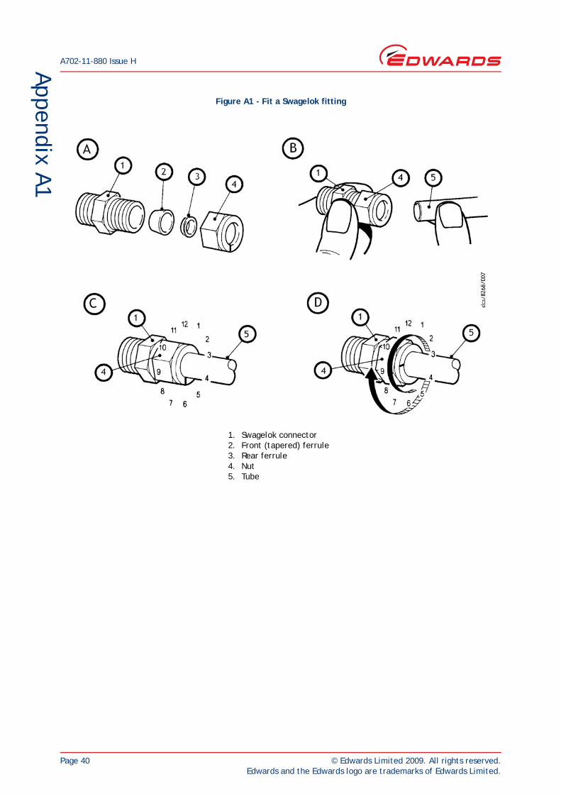
A702-11-880 Issue H
Page 40 © Edwards Limited 2009. All rights reserved.Edwards and the Edwards logo are trademarks of Edwards Limited.
Appendix A1
Figure A1 - Fit a Swagelok fitting
1. Swagelok connector2. Front (tapered) ferrule3. Rear ferrule4. Nut5. Tube
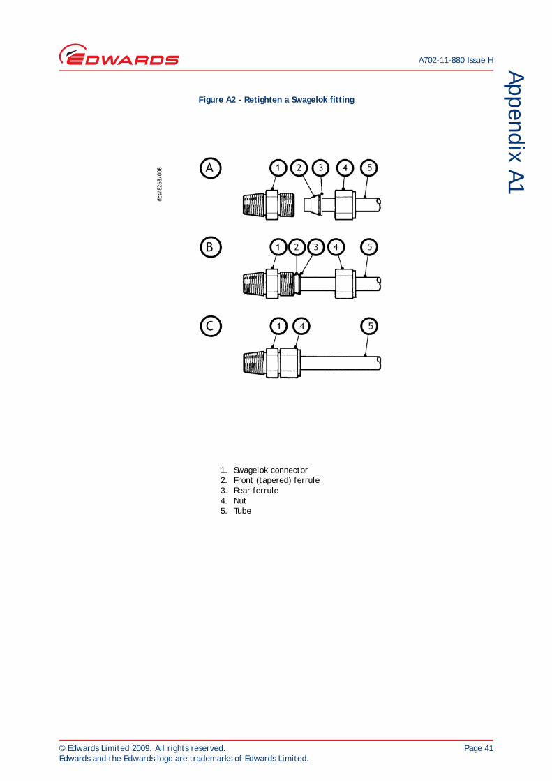
© Edwards Limited 2009. All rights reserved. Page 41Edwards and the Edwards logo are trademarks of Edwards Limited.
Appendix A1A702-11-880 Issue H
Figure A2 - Retighten a Swagelok fitting
1. Swagelok connector2. Front (tapered) ferrule3. Rear ferrule4. Nut5. Tube

A702-11-880 Issue H
Page 42 © Edwards Limited 2009. All rights reserved.Edwards and the Edwards logo are trademarks of Edwards Limited.
This page has been intentionally left blank.