Embed Size (px)
Citation preview

GBPPR 'Zine
Issue #19 / The Monthly Journal of the American Hacker / October 2005
"If you want a copy of the source code (with comments), send $10 to 2600 Worm,PO Box 752, Middle Island, NY 11953."
"A FULL PAGE AD in 2600 costs only $200. Half page $100. Contact 2600Advertising, PO Box 762, Middle Island, NY 11953."
Table of Contents
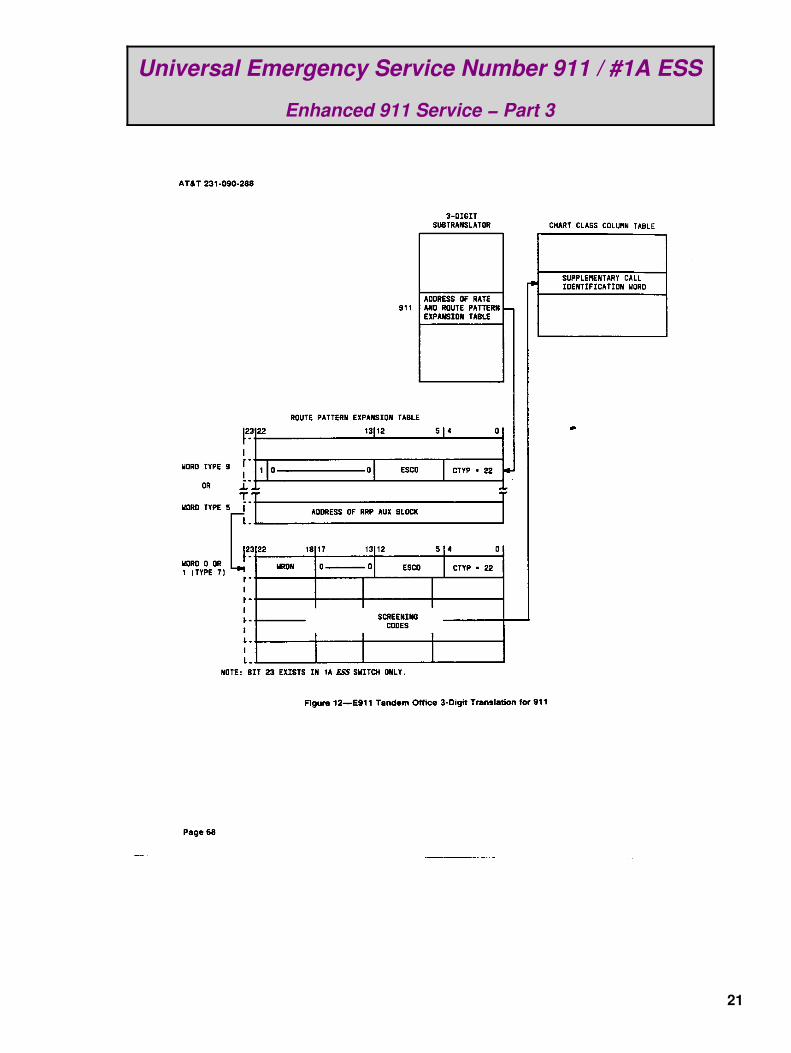
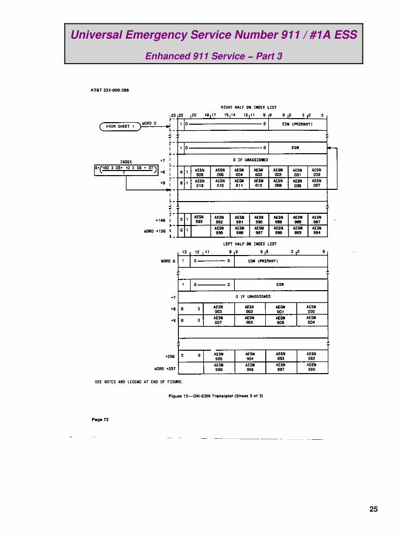
Page 2 / Universal Emergency Service Number 911 / #1A ESS − Enhanced 911 Service (Part 3)♦ Third part of a four part series on the E911 system under a #1A ESS.♦
Page 26 / GBPPR Telephone Induction Tap♦ Monitor a phone line without a direct physical connection.♦
Page 37 / Lucent #5 ESS Routine Operations and Maintenance Procedures♦ Overview of a few routine procedures on a #5 ESS♦
Page 65 / Nortel DMS−100 Line−to−Treatment Translations♦ How a call is routed to an announcement on a DMS−100.♦
Page 88 / Nortel DMS−100 Command Screening Table (CMDS)♦ Permission settings for DMS−100 commands.♦
Page 91 / Nortel DMS−100 Calling Line Identification Table (CLIDN)♦ It's not a good thing if your BBS number appears here.♦
Page 94 / Bonus♦ CIA Career Ad: Overseas Careers.♦ CIA Career Ad: Photographers.♦
Page 96 / The End♦ Editorial and rants.♦
1

Universal Emergency Service Number 911 / #1A ESS
Enhanced 911 Service − Part 3
Continued from Issue #18
2

Universal Emergency Service Number 911 / #1A ESS
Enhanced 911 Service − Part 3
3

Universal Emergency Service Number 911 / #1A ESS
Enhanced 911 Service − Part 3
4

Universal Emergency Service Number 911 / #1A ESS
Enhanced 911 Service − Part 3
5

Universal Emergency Service Number 911 / #1A ESS
Enhanced 911 Service − Part 3
6

Universal Emergency Service Number 911 / #1A ESS
Enhanced 911 Service − Part 3
7
Universal Emergency Service Number 911 / #1A ESS
Enhanced 911 Service − Part 3
8

Universal Emergency Service Number 911 / #1A ESS
Enhanced 911 Service − Part 3
9

Universal Emergency Service Number 911 / #1A ESS
Enhanced 911 Service − Part 3
10

Universal Emergency Service Number 911 / #1A ESS
Enhanced 911 Service − Part 3
11

Universal Emergency Service Number 911 / #1A ESS
Enhanced 911 Service − Part 3
12
Universal Emergency Service Number 911 / #1A ESS
Enhanced 911 Service − Part 3
13

Universal Emergency Service Number 911 / #1A ESS
Enhanced 911 Service − Part 3
14

Universal Emergency Service Number 911 / #1A ESS
Enhanced 911 Service − Part 3
15
Universal Emergency Service Number 911 / #1A ESS
Enhanced 911 Service − Part 3
16

Universal Emergency Service Number 911 / #1A ESS
Enhanced 911 Service − Part 3
17

Universal Emergency Service Number 911 / #1A ESS
Enhanced 911 Service − Part 3
18

Universal Emergency Service Number 911 / #1A ESS
Enhanced 911 Service − Part 3
19

Universal Emergency Service Number 911 / #1A ESS
Enhanced 911 Service − Part 3
20
Universal Emergency Service Number 911 / #1A ESS
Enhanced 911 Service − Part 3
21

Universal Emergency Service Number 911 / #1A ESS
Enhanced 911 Service − Part 3
22

Universal Emergency Service Number 911 / #1A ESS
Enhanced 911 Service − Part 3
23

Universal Emergency Service Number 911 / #1A ESS
Enhanced 911 Service − Part 3
24
Universal Emergency Service Number 911 / #1A ESS
Enhanced 911 Service − Part 3
25

GBPPR Telephone Induction Tap
Overview
An inductive telephone tap is a device to surreptitiously intercept the audio on an analog telephoneline without the need for any direct physical connection. This makes detection fairly difficult.
For instance, lets say you want to monitor a telephone line at the corporate office of $2600Magazine to make sure they are staying away from little boys...
You'd first locate their telephone line pair within a wiring closet, outside network interface, or in aterminal box somewhere downstream. Next, you'd slip the ferrite pick−up coil over only one of thetwo wires making up the telephone line pair. It can be either ring or tip, it doesn't matter. Thereason you can only use one wire is that a telephone line pair is a balanced transmission line. Thismeans that if the two wires where to pass through the same ferrite core, the out−of−phase signalswould cancel each other! Now, due to real−world conditions, telephone lines are not perfectlybalanced, but always try for a proper pick−up connection.
Wait for them to use the phone. When they do, the audio should be crystal clear. The GBPPRTelephone Induction Tap uses proper pick−up coil impedance matching and low and high passfilters to remove any static or hum from the audio signal.
Get your goods on Golddigger and then cancel that subscription. Free Kevin? No thanks...
Circuit Operation
This induction tap circuit varies dramatically from other common designs which appear on theInternet. The first major change is that the split−core ferrite pick−up coil is designed for anapproximate 8 ohms impedance (@ 1 kHz). This is done by wrapping one side of the split−coreferrite with enameled 30−gauge magnet wire (Radio Shack part # 278−1345) until the inductancevalue measures approximately 1.3 µH. Try to keep the wrapped wire "flush" with the inside of theferrite core. If you don't have an inductance meter, try just wrapping about 100 turns or so. Theexact model of the split−core ferrite can be quite critical. All Electronics,http://www.allelectronics.com, carries several varities of "ferrite split beads with snap sleeves." Partnumbers FB−53 or FB−48 look like they could work and those "suction cup" pick−up coils will workin a pinch. The ferrite pick−up core's output is wired as a balanced connection. You'll need to use ashielded two−line wire to connect it back to the audio preamplifier. Balanced microphone wireworks wonderfully. Only connect the wire's shield to ground on the audio preamplifier side.
Next, that signal is fed into a 8 ohm to 1,000 ohm impedance matching transformer. This isdesigned to "step−up" the low−impedance of the pick−up coil for better matching to the first LM833op−amp in the low−noise preamplifier circuit. Surprisingly, that impedance matching transformer isavailable from Radio Shack, part # 273−1380. The transformer's RED and WHITE wires are on thethe "8 ohm" side and the GREEN and BLUE wires form the "1,000 ohm" side. The BLACK centertap wire is not used and should be cut off. The second op−amp of the LM833 is wired as a DC biasgenerator. This allows the LM833 to operate without the need for a negative voltage, which can addexcess switching noise. A 100 kohm potentiometer controls the gain of the LM833, up to around 40dB. The 220 pF capacitor rolls−off the LM833's high−frequency response.
After amplification, the signal is sent through a simple high−pass filter consisting of a series 0.1 µFcap and shunt 5.6 kohm resistor. The signal is then sent to a Maxim MAX295 8th−order, low−pass
26

switched capacitor filter. The MAX295 is wired as a variable cut−off, low−pass filter with amaximum frequency of approximately 6 kHz. The MAX295 also naturally attenuates any 50/60 Hzinduced hum. The MAX295's output routes through a 10 kHz low−pass filter to attenuate anyhigh−frequency clock noise. A CMOS 555−timer (Radio Shack part # 276−1718) generates theMAX295's needed clock signals. The 555−timer should be CMOS for the best and most stableperformance. A 10 kohm potentiometer controls the frequency of the 555's clock signals. They'llvary from about 30 kHz to up around 500 kHz. This corresponds to a variable low−pass frequencycut−off in the MAX295 from around 600 Hz to 10 kHz. Fiddle with the 555's 1000 pF timingcapacitor to change the clock frequency.
The signal is then fed to a TL071 op−amp configured as a 300 Hz high−pass filter. This furtherattenuates any 50/60 Hz hum and any other low−frequency rumbles.
Finally, the signal is fed to a LM386 audio amplifier (Radio Shack part # 276−1731). The LM386 isonly designed to drive low−impedance (8, 16 or 32 ohm) headphones or speakers. The 10 µFcapacitor across pins 1 & 8 of the LM386 is not needed if you only use headphones. To connectthe audio output to a tape recoder, get another 8 ohm to 1,000 ohm impedance matchingtransformer and wire the 8 ohm side to the LM386's audio output and the 1,000 ohm side to thetape recorder input. Or tap the wiper of the 10 kohm volume pot directly, if you're so inclined.
Power is provided via a standard 9 volt battery. +5 VDC regulation is taken through a 78L05. −5VDC is generated via a Maxim MAX660 voltage inverter. The MAX660 can source a higher outputcurrent and has a higher switching frequency, which is useful for this circuit.
Try to use 1% tolerance, metal−film resistors throughout the circuit. They offer the highest stabilityand lowest noise. Audio coupling capacitors and capacitors in the filters should be of film(polystyrene, mylar, etc.) dielectric. These are the "quietest" as they are not microphonic. Build theentire circuit into a metal box and always use a new, fresh 9 volt alkaline battery. Twist the wireleads from the potentiometers and audio output to reduce noise pick−up. Use a printed circuitboard with a large ground plane and try to keep the input and outputs separated to avoid feedbackoscillations.
Detecting an Inductive Phone Tap
Yes, you can detect an inductive phone tap. Physical inspection is always the best, but a devicecalled a Time Domain Reflectometer (TDR) can also be used. This is a device which sends aseries of fast−rising (picosecond) pulses down a wire, then monitors their reflection on anoscilloscope. Sort of like a hard−wired radar. Since the ferrite pick−up core is an inductor, thereturned signal will be distorted, as some of the energy of the transmitted pulse is "absorbed" intothe ferrite. To counter a TDR, place the tap after a loading coil placed on the telephone wire pair oruse a very small ferrite pick−up core. Also, you can place a tone (milliwatt, tone sweep generator,etc.) on your telephone line and probe around the terminal box looking for the tone to show up onanother pair or any other suspicious wires. If you were to call your local milliwatt plant test numberand you heard that 1,004 Hz tone while scanning the airwaves with your Radio Shack scanner...well... that wouldn't be good.
27
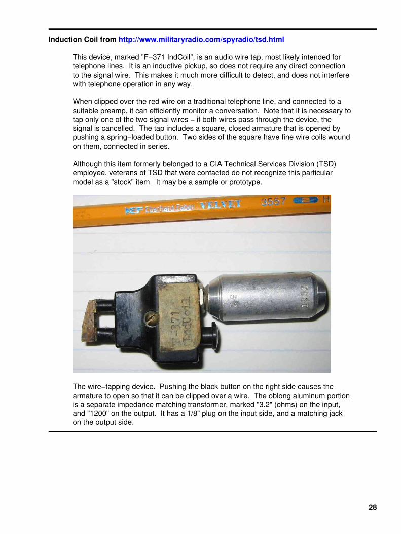
Induction Coil from http://www.militaryradio.com/spyradio/tsd.html
This device, marked "F−371 IndCoil", is an audio wire tap, most likely intended fortelephone lines. It is an inductive pickup, so does not require any direct connectionto the signal wire. This makes it much more difficult to detect, and does not interferewith telephone operation in any way.
When clipped over the red wire on a traditional telephone line, and connected to asuitable preamp, it can efficiently monitor a conversation. Note that it is necessary totap only one of the two signal wires − if both wires pass through the device, thesignal is cancelled. The tap includes a square, closed armature that is opened bypushing a spring−loaded button. Two sides of the square have fine wire coils woundon them, connected in series.
Although this item formerly belonged to a CIA Technical Services Division (TSD)employee, veterans of TSD that were contacted do not recognize this particularmodel as a "stock" item. It may be a sample or prototype.
The wire−tapping device. Pushing the black button on the right side causes thearmature to open so that it can be clipped over a wire. The oblong aluminum portionis a separate impedance matching transformer, marked "3.2" (ohms) on the input,and "1200" on the output. It has a 1/8" plug on the input side, and a matching jackon the output side.
28

Induction Telephone Tap from H. Keith Melton's Ultimate Spy
29
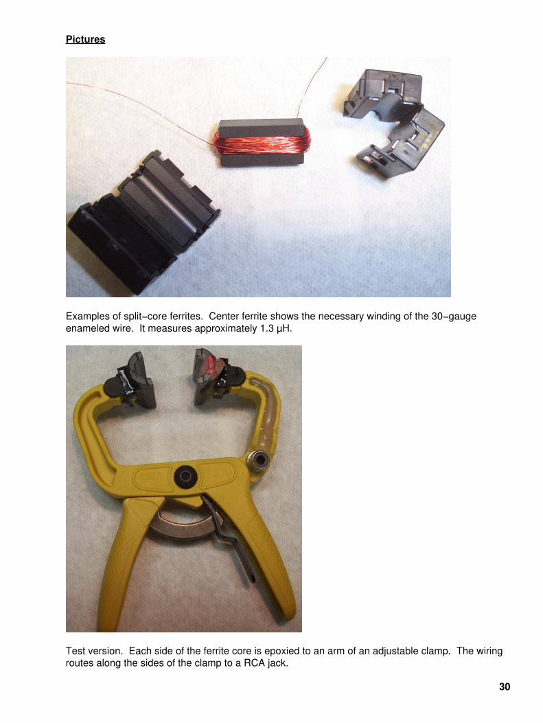
Pictures
Examples of split−core ferrites. Center ferrite shows the necessary winding of the 30−gaugeenameled wire. It measures approximately 1.3 µH.
Test version. Each side of the ferrite core is epoxied to an arm of an adjustable clamp. The wiringroutes along the sides of the clamp to a RCA jack.
30

Working version. The RCA jack was replaced with a piece of microphone wire connected to a1/4−inch stereo plug. The 30−gauge windings go to the ring and tip of the 1/4−inch plug and theshield to the sleeve.
31

Closeup picture. Several layers of epoxy are used to build up and protect the wiring. The top ferritecore is epoxied directly to the clamp's arm, so it can't move.
Top, side view. Note the 30−gauge wire embedded in the epoxy.
32

Closeup picture of the ferrite cores. The one on the left is adjustable, the one on the right isfixed. The white stuff on the 30−gauge wiring is Q−Dope to secure and protect the enameled wire.
Picture of the audio amplifer and filtering board. The impedance matching transformer is on theupper left, LM833 is to the right of the transformer. The MAX295 is then to the right of theLM833. Below the MAX295 is the TL071 op−amp. The large, yellow capacitors arepolystyrene. To the left of the TL071 is the LM386. Above the LM386 is the CMOS 555−timer. Thelittle IC to the left of the 555 is the MAX660. Inbetween the two blue electrolytic caps is the 78L05.
33

Front panel overview. It's an old printer switch case and is a tad too small, but works. Fc is theMAX295 frequency cut−off control, VOL is the volume control with an integrated on/off powerswitch, GAIN is the LM833's gain control pot. OUT is a 1/4−inch mono jack and IN is a 1/4−inchstereo jack. I have no idea what the green thing that looks like an LED is.
Internal view with everything connected. Use double−sided foam tape to mount the PC board. Thenormally closed contact on the 1/4−inch output jack has a 100 ohm resistor wired to ground. Thisprevents any circuit oscillation in case headphones are not connected while powered. Twist thewires to reduce noise pickup.
34
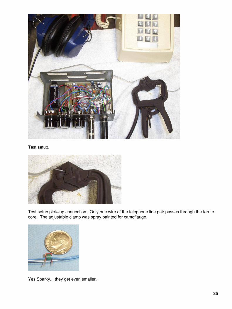
Test setup.
Test setup pick−up connection. Only one wire of the telephone line pair passes through the ferritecore. The adjustable clamp was spray painted for camoflauge.
Yes Sparky... they get even smaller.
35

36

Lucent #5 ESS Routine Operations and Maintenance Procedures
Purpose
This Routine Operations and Maintenance Manual contains both descriptive material and detailedprocedures for routine operations and maintenance of the Lucent #5 ESS switch. This manualcovers the 5E2(2) through 5E8 software releases. As the #5 ESS switch continues to evolve, thismanual will be reissued to cover future software releases.
This manual is primarily intended for telephone company personnel who schedule or performroutine maintenance for the #5 ESS switch.
Alarm System Management
General
The alarm system management is used to set or clear manual or automatic alarm release, to assignlevel and labels on scan points, and to provide alarm control.
Alarm Release
The critical and major alarms in an exchange can be released manually or automatically. When thealarm mode is manual, the alarms have to be released by pressing the ALM RLS function key at theMaster Control Center (MCC) video terminal. If the alarm mode is set to automatic release, thealarms will be released in 5 seconds by the system.
Automatic or manual alarm release can also be activated by means of the menu commands 800and 801 at the MCC Pages 105/106 − BLDG/POWER & ALARM CNTRLS. Minor alarms will bereleased automatically all the time, independent of the alarm release mode.
Alarm Level and Label Assignments
Alarm level and label assignments can be given to building or miscellaneous alarms. Theassignments are shown at the MCC Pages 105/106 − BLDG/POWER & ALARM CNTRLS and Page119 − MISCELLANEOUS ALARMS. The alarm level can be major or minor.
The label can consist of a maximum of nine upper−case characters, that is, letters, digits, spaces,plus, or minus signs. When a label has been assigned, the report data will show the old and newlabel. Once level and label are filled in, they are protected from loss when the system is booted.
Alarm Controls
Some alarms can be inhibited or allowed manually from alarm reporting. These alarms are asfollows:
Building power alarms• External sanity power alarm• Fan or fuse alarms of the Time Multiplex Switch (TMS) or the Message Switch (MSGS)• Miscellaneous alarms•
When a building power alarm is inhibited, the respective indicator at the MCC Page 105/106 willshow the abbreviation "INH" in reverse video. Also the words "BLDG INH" in the SUMMARY
37

STATUS AREA will be backlighted. To inhibit or allow building power alarms, one can use theappropriate input message or the menu command (shown at the MCC Page 105/106).
The external sanity monitor power alarm indicator is shown at the MCC Page 116 −MISCELLANEOUS. Once the alarm is inhibited, the "INHIBIT" indicator will be in reverse video. Alsothis alarm can be inhibited or allowed by either the input message or the menu command at theappropriate MCC page.
The MSGS, TMS, and ONTC fan or fan fuse alarms can be inhibited by the system. When such analarm is inhibited, this is shown at MCC Page 115 − COMMUNICATION MODULE SUMMARY. Thereason an alarm will be inhibited is because the respective scan point is chattering. After solvingthe problem, the alarm can be allowed again by entering the input message:
If Man−Machine Language (MML):
ALW:ALM,MSGS=b;orALW:ALM,TMS=b;orALW:ALM,ONTC=b;
If Program Documentation Standard (PDS):
ALW:ALM,MSGS b!orALW:ALM,TMS b!orALW:ALM,ONTC b!
Where: b = Unit Number 0 or 1.
The miscellaneous alarms can be allowed or inhibited manually by means of the appropriate inputmessage or the menu command at the MCC Page 119 − MISCELLANEOUS ALARMS. When thealarm is inhibited, the "INH" indicator will backlight. Also the "INHIBIT" indicator ofMISCELLANEOUS ALARMS at MCC Page 116 will be in reverse video. The miscellaneous framefuse alarm can be inhibited by the system once the scan point is chattering. After solving theproblem, the alarm can be allowed by entering the following input message:
If MML:
ALW:ALM,MFFUSE=b;
If PDS:
ALW:ALM,MFFUSE b!
Where: b = Miscellaneous Frame Fuse Unit Number 0 or 1.
When this alarm is inhibited, the abbreviation "INH" is displayed in reverse video at the right of MISCFRAME FUSE ALARM.
38

File and File System Management
Introduction
Maintaining the file system includes the following:
Checking the file system resources• Manipulating files• Using the file system audits• File system corruption detection [System Integrity Verification (SIV)]• Backing up and restoring file systems•
General
This subject lists and briefly describes the input messages and reports used in managing files andthe file system. These messages and responses are used in performing various actions such asreporting the contents of a file or directory and copying a file from an active disk to an offline orout−of−service disk.
The input/output messages are categorized according to the function performed on the file or filesystem and how they are used (type). The different functions and the corresponding tables are asfollows:
File System Control − Table A• File Modification and Retrieval − Table B• File Transfer and Backup − Table C• Maintenance Tools − Table D•
The three types of input/output messages are routine, troubleshooting, and permanent. Routinemessages are used periodically to determine actual or potential troubles in the system. Thetroubleshooting messages are used to clear troubles and will not cause permanent changes to thesystem. The messages labeled permanent can cause permanent changes in the file structure orprocess structure of the system. Permanent messages should be used upon concurrence with thelocal technical assistance organization or as directed in a software update.
A detailed description of these input messages can be found in AT&T 235−600−700 (formerly,IM−5D000−01) and a detailed description of these output messages can be found in AT&T235−600−750 (formerly, OM−5D000−01).
Checking File System Resources
The REPT FS output message warns that a file system is about to run out of space. Immediateaction must be taken to provide more space in the file system. Contact your technical assistanceorganization to determine the files that can be removed to provide file system space (for example,software update history).
File system free space can be monitored and action can be taken before the free space is usedup. The command OP:STATUS:FREEDISK reports the free space and free i−nodes in the mountedfile systems. Monitor these numbers regularly to determine if space or i−nodes are being depleted.
Running the file system block audit may increase the free space in a file system if the audit findslost resources that it can recover. Note that no error is reported when lost free disk blocks arerecovered.
39

The allocation of disk space to contiguous files is limited to the size of the largest set of contiguousfree disk blocks in the file system. In a fragmented file system, this may be considerably less thantotal free space. The compaction audit can be used to increase the size of the contiguous free diskspace.
−−−−−−−−−−−−−−−−−−−−−−−−−−−−−−−−−−−−−−−−−−−−−−−−−−−−−−−−−−−−−−−−−−−−−−−−−−−−−−−−−−−−−−−−−File System Control − Table A
Message/Response Name Type Description−−−−−−−−−−−−−−−−−−−−−−−−−−−−−−−−−−−−−−−−−−−−−−−−−−−−−−−−−−−−−−−−−−−−−−−−−−−−−−−−−−−−−−−−−ALW:FSYS−ACCESS Permanent Changes access permissions of files.−−−−−−−−−−−−−−−−−−−−−−−−−−−−−−−−−−−−−−−−−−−−−−−−−−−−−−−−−−−−−−−−−−−−−−−−−−−−−−−−−−−−−−−−−ALW:FSYS−MOUNT Permanent Mounts an unmounted file system so that the system can access files in the file system.−−−−−−−−−−−−−−−−−−−−−−−−−−−−−−−−−−−−−−−−−−−−−−−−−−−−−−−−−−−−−−−−−−−−−−−−−−−−−−−−−−−−−−−−−CLR:FSYS−OWNER Permanent Changes the owner of a file. All operating system files are owned by root.−−−−−−−−−−−−−−−−−−−−−−−−−−−−−−−−−−−−−−−−−−−−−−−−−−−−−−−−−−−−−−−−−−−−−−−−−−−−−−−−−−−−−−−−−CLR:FSYS−DIR Permanent Removes a directory from the file system.−−−−−−−−−−−−−−−−−−−−−−−−−−−−−−−−−−−−−−−−−−−−−−−−−−−−−−−−−−−−−−−−−−−−−−−−−−−−−−−−−−−−−−−−−CLR:FSYS−FILE Permanent Removes a file from the file system.−−−−−−−−−−−−−−−−−−−−−−−−−−−−−−−−−−−−−−−−−−−−−−−−−−−−−−−−−−−−−−−−−−−−−−−−−−−−−−−−−−−−−−−−−COPY:FSYS−CFILE Permanent Copies a file to a contiguous area of the disk. Contiguous files are transferred from disk to main memory more quickly than regular files.−−−−−−−−−−−−−−−−−−−−−−−−−−−−−−−−−−−−−−−−−−−−−−−−−−−−−−−−−−−−−−−−−−−−−−−−−−−−−−−−−−−−−−−−−COPY:FSYS−FILE Permanent Makes another copy of a file in a different directory. The copied file has the same name as the original file.−−−−−−−−−−−−−−−−−−−−−−−−−−−−−−−−−−−−−−−−−−−−−−−−−−−−−−−−−−−−−−−−−−−−−−−−−−−−−−−−−−−−−−−−−IN:FSYS−DIR Permanent Creates a new directory in the file system.−−−−−−−−−−−−−−−−−−−−−−−−−−−−−−−−−−−−−−−−−−−−−−−−−−−−−−−−−−−−−−−−−−−−−−−−−−−−−−−−−−−−−−−−−OP:ST−DISKUSE Troubleshooting Reports the number of blocks contained in all files and directories within each specified directory or file name.−−−−−−−−−−−−−−−−−−−−−−−−−−−−−−−−−−−−−−−−−−−−−−−−−−−−−−−−−−−−−−−−−−−−−−−−−−−−−−−−−−−−−−−−−OP:ST−FILESYS Routine Lists all currently mounted file systems, the directory under which they are mounted, and the time they were mounted.−−−−−−−−−−−−−−−−−−−−−−−−−−−−−−−−−−−−−−−−−−−−−−−−−−−−−−−−−−−−−−−−−−−−−−−−−−−−−−−−−−−−−−−−−OP:ST−FREEDISK Routine Lists the mounted file systems with the number of free blocks and free i−nodes. Used to determine if file system space is being depleted.−−−−−−−−−−−−−−−−−−−−−−−−−−−−−−−−−−−−−−−−−−−−−−−−−−−−−−−−−−−−−−−−−−−−−−−−−−−−−−−−−−−−−−−−−OP:ST−LISTDIR Routine Reports the contents of a specific directory or file.−−−−−−−−−−−−−−−−−−−−−−−−−−−−−−−−−−−−−−−−−−−−−−−−−−−−−−−−−−−−−−−−−−−−−−−−−−−−−−−−−−−−−−−−−REPT:FILESYS Troubleshooting This autonomous report warns that a file system within the central processor is about to run out of space.−−−−−−−−−−−−−−−−−−−−−−−−−−−−−−−−−−−−−−−−−−−−−−−−−−−−−−−−−−−−−−−−−−−−−−−−−−−−−−−−−−−−−−−−−Note: The message/response names as presented in these tables are not intended to be typed into the system. These names are provided so the user can reference these messages in AT&T 235−600−700, Input Message Manual, and AT&T 235−600−750, Output Message Manual, for the correct syntax.−−−−−−−−−−−−−−−−−−−−−−−−−−−−−−−−−−−−−−−−−−−−−−−−−−−−−−−−−−−−−−−−−−−−−−−−−−−−−−−−−−−−−−−−−−End−
40

−−−−−−−−−−−−−−−−−−−−−−−−−−−−−−−−−−−−−−−−−−−−−−−−−−−−−−−−−−−−−−−−−−−−−−−−−−−−−−−−−−−−−−−−−File Modification and Retrieval − Table B
Message/Response Name Type Description−−−−−−−−−−−−−−−−−−−−−−−−−−−−−−−−−−−−−−−−−−−−−−−−−−−−−−−−−−−−−−−−−−−−−−−−−−−−−−−−−−−−−−−−−IN:F−APND−A Permanent Appends a line to an ASCII file.−−−−−−−−−−−−−−−−−−−−−−−−−−−−−−−−−−−−−−−−−−−−−−−−−−−−−−−−−−−−−−−−−−−−−−−−−−−−−−−−−−−−−−−−−IN:F−DEL Permanent Deletes one or more lines from an ASCII file.−−−−−−−−−−−−−−−−−−−−−−−−−−−−−−−−−−−−−−−−−−−−−−−−−−−−−−−−−−−−−−−−−−−−−−−−−−−−−−−−−−−−−−−−−IN:F−REPL Permanent Replaces lines in an ASCII file with user supplied lines.−−−−−−−−−−−−−−−−−−−−−−−−−−−−−−−−−−−−−−−−−−−−−−−−−−−−−−−−−−−−−−−−−−−−−−−−−−−−−−−−−−−−−−−−−DUMP:F−ALL Troubleshooting Prints the contents of an ASCII file on the Receive−Only Printer (ROP).−−−−−−−−−−−−−−−−−−−−−−−−−−−−−−−−−−−−−−−−−−−−−−−−−−−−−−−−−−−−−−−−−−−−−−−−−−−−−−−−−−−−−−−−−DUMP:F−DATA Troubleshooting Prints the contents of a file in the specified format.−−−−−−−−−−−−−−−−−−−−−−−−−−−−−−−−−−−−−−−−−−−−−−−−−−−−−−−−−−−−−−−−−−−−−−−−−−−−−−−−−−−−−−−−−DUMP:F−PARTL Troubleshooting Prints one or more lines of an ASCII file.−−−−−−−−−−−−−−−−−−−−−−−−−−−−−−−−−−−−−−−−−−−−−−−−−−−−−−−−−−−−−−−−−−−−−−−−−−−−−−−−−−−−−−−−−−End−
−−−−−−−−−−−−−−−−−−−−−−−−−−−−−−−−−−−−−−−−−−−−−−−−−−−−−−−−−−−−−−−−−−−−−−−−−−−−−−−−−−−−−−−−−File Transfer and Backup − Table C
Message/Response Name Type Description−−−−−−−−−−−−−−−−−−−−−−−−−−−−−−−−−−−−−−−−−−−−−−−−−−−−−−−−−−−−−−−−−−−−−−−−−−−−−−−−−−−−−−−−−COPY:ACTDISK Permanent Copies a file from an active disk to an offline or out−of−service disk.−−−−−−−−−−−−−−−−−−−−−−−−−−−−−−−−−−−−−−−−−−−−−−−−−−−−−−−−−−−−−−−−−−−−−−−−−−−−−−−−−−−−−−−−−COPY:CPOOSF Permanent Copies a file from an out−of−service disk to an active disk.−−−−−−−−−−−−−−−−−−−−−−−−−−−−−−−−−−−−−−−−−−−−−−−−−−−−−−−−−−−−−−−−−−−−−−−−−−−−−−−−−−−−−−−−−COPY:CPSPDISK Permanent Copies a specific partition or a list of partitions from one of the system disks to an active spare disk.−−−−−−−−−−−−−−−−−−−−−−−−−−−−−−−−−−−−−−−−−−−−−−−−−−−−−−−−−−−−−−−−−−−−−−−−−−−−−−−−−−−−−−−−−COPY:PTN:ALL Permanent Copies one set of partitions into a corresponding set of partitions. This message is used to recover mutilated disk partitions from backup disk partitions and to generate partition backup copies.−−−−−−−−−−−−−−−−−−−−−−−−−−−−−−−−−−−−−−−−−−−−−−−−−−−−−−−−−−−−−−−−−−−−−−−−−−−−−−−−−−−−−−−−−COPY:TAPE−IN Permanent Copies files from a magnetic tape containing full or relative pathnames and header information, and places them in their respective directories. The message can also print a table of contents of the tape.−−−−−−−−−−−−−−−−−−−−−−−−−−−−−−−−−−−−−−−−−−−−−−−−−−−−−−−−−−−−−−−−−−−−−−−−−−−−−−−−−−−−−−−−−COPY:TAPE−OUT Permanent Copies one or more files to a magnetic tape along with relative pathnames and header information.−−−−−−−−−−−−−−−−−−−−−−−−−−−−−−−−−−−−−−−−−−−−−−−−−−−−−−−−−−−−−−−−−−−−−−−−−−−−−−−−−−−−−−−−−−End−
41

−−−−−−−−−−−−−−−−−−−−−−−−−−−−−−−−−−−−−−−−−−−−−−−−−−−−−−−−−−−−−−−−−−−−−−−−−−−−−−−−−−−−−−−−−Maintenance Tools − Table D
Message/Response Name Type Description−−−−−−−−−−−−−−−−−−−−−−−−−−−−−−−−−−−−−−−−−−−−−−−−−−−−−−−−−−−−−−−−−−−−−−−−−−−−−−−−−−−−−−−−−OP:ST−SUM Routine Calculates a checksum for a given file and prints the number of blocks in the file.−−−−−−−−−−−−−−−−−−−−−−−−−−−−−−−−−−−−−−−−−−−−−−−−−−−−−−−−−−−−−−−−−−−−−−−−−−−−−−−−−−−−−−−−−VFY:TAPE Routine Verifies the readability of information on system tapes and the consistency of corresponding hash sums.−−−−−−−−−−−−−−−−−−−−−−−−−−−−−−−−−−−−−−−−−−−−−−−−−−−−−−−−−−−−−−−−−−−−−−−−−−−−−−−−−−−−−−−−−−End−
Copying Files to Nonactive Disks − Utility Requirements
The active/nonactive disk copy utility copies a file from an active to a nonactive disk. The file can bea regular file, a contiguous file (type C or x), or a block device file (type b which consists of apartition or a file system).
The use this facility, the user needs to specify the following:
The number of the destination disk: This disk must be Out−of−Service (OOS) or Offline (OFL) and does nothave to be a mate of the Active (ACT) disk.
•
The full pathname of the source file that exists on an ACT disk: If the source is a regular or contiguous file,then this file must exist on a mounted file system.
•
The full pathname or number of the destination partition on the nonactive disk: If a name is specified, thenit must exist as a special device file on the active disk. If the source is a regular or contiguous file, then thispartition must be a file system.
•
The pathname on the destination partition where the file is to be written: If the destination pathname is notspecified, then the pathname of the source file will be used. If the destination pathname starts with a "/", thenthe mount point will be excluded from it (destination pathname). It is not required that all directories in thepathname specified exist.
•
Emergency Dump
On disk, a partition is reserved for emergency dump. When there has been data written in thispartition, an autonomous report (REPT EMERGENCY DUMP PARTITION FULL) will beprinted. When data has been written in the emergency dump partition, the emergency dump statusflag will be set. Due to the status flag, the previously mentioned report will be printedperiodically. When the flag has been set, no other emergency dump can be written within the next12 hours. Therefore, an input message in present to clear the status flag. This message must onlybe used when the dumped data has been saved. As soon as the status flag has been cleared, theemergency dump partition is marked empty. The message to clear the status flag isCLR:EMERDUMP;. Before saving the data, the status has to be investigated. This is done bymeans of the input message OP:EMERSTAT;. This will result in a report indicating on which disk,MHD 0 or 1, the data has been dumped, how many bytes have been written, and the hexadecimaladdress of each segment written. To save the dumped data, an emergency dump and beperformed.
42

Log File Handling
General
Hardware and software errors will generate error reports. These reports will either be printed on theROP, collected in the log file, or both. The message class of the report is decisive whether a reportwill either be logged, printed or both.
In software release 5E2(1), when there are reports of a certain message class, which are normallylogged, the user can change the log option to log and print. This can be done by means of the inputmessage SET:LPS. If there are reports of a message class, which have only the print option, theuser can change those reports to print and log with the same message previously mentioned. Tochange the options to their original value, the input message CLR:LPS,MSGCLS=ALL; can beused. It is not possible to change a message class from the original print option to a log−only optionor vice versa.
In software releases 5E2(2) through 5E7, the user can change the log or print option with the inputmessage CHG:LPS?. This will direct the output to the DAYLOG file or print the data at the devicesspecified in the Equipment Configuration Database (ECD) for that message class. The OP:LPS?message can be used to determine the current log and print status of a message class.
On MCC display Page 110 − SYSTEM INHIBITS, the poke command 411 can be entered to set allapplicable message classes to log and print.
Log files can be used to do the following:
Detect and correct transient errors: Correctable memory errors can occur at an increasing rate over manydays. This problem can be detected by studying the log file entries.
•
Determine a chronological order of events: This can be done by putting entries from several log filestogether.
•
Log files are determined in the classdef and device forms in the ECD. All log files are located in thedirectory /etc/log, if 5E2(2) through 5E5, or /var/log, if 5E6 or later. The pathname for eachlog file is defined in the particular device form.
Size of Log Files
To prevent a file system overflow, the files are limited in size. When a log file is first created, the filewill be called XXXXX1, where XXXXX stands for the log filename. When half of the disk space isused, the contents of XXXXX1 is copied into XXXXX0, and the most recent information will be storedin XXXXX1 again. When all disk space is used, the "1−part" is again copied into the "0−part" whichwill overwrite the old information by then and the "1−part" will be filled again with the most recentinformation. Each log file entry has time of day information, real−time clock values, and sequencenumbers.
The log files must be dumped at regular intervals to avoid losing the contents of the files. It isadvisable to dump the files once a day.
The available space in the log file for operations on recent change data, RCLOG, can be obtainedby using the OP:AVAILLOG; input message.
43

Types of Log Files
There are several log files present in the exchange. Most of them are related to the AdministrativeModule (AM). Table E shows the log files related to the AM. Table F shows the log files related torecent change and equipment data an input messages.
−−−−−−−−−−−−−−−−−−−−−−−−−−−−−−−−−−−−−−−−−−−−−−−−−−−−−−−−−−−−−−−−−−−−−−−−−−−−−−−−−−−−−−−−−Review of the Log Files Related to the AM − Table E
Log File Description−−−−−−−−−−−−−−−−−−−−−−−−−−−−−−−−−−−−−−−−−−−−−−−−−−−−−−−−−−−−−−−−−−−−−−−−−−−−−−−−−−−−−−−−−CONFLOG Configuration management log file. This file contains a record of each error detected in a hardware unit. Activation of storing the information in CONFLOG is done by the ALW:CNFLG message.−−−−−−−−−−−−−−−−−−−−−−−−−−−−−−−−−−−−−−−−−−−−−−−−−−−−−−−−−−−−−−−−−−−−−−−−−−−−−−−−−−−−−−−−−ERLOG Error interrupt log file. This file contains Control Unit (CU) error interrupts, except memory related ones.−−−−−−−−−−−−−−−−−−−−−−−−−−−−−−−−−−−−−−−−−−−−−−−−−−−−−−−−−−−−−−−−−−−−−−−−−−−−−−−−−−−−−−−−−MEMLOG Memory history log file. This file contains the supplementary data for memory error interrupts. This log file will be used to locate transient memory failures.−−−−−−−−−−−−−−−−−−−−−−−−−−−−−−−−−−−−−−−−−−−−−−−−−−−−−−−−−−−−−−−−−−−−−−−−−−−−−−−−−−−−−−−−−IODRVLOG Input/output driver log file. This file contains the error reports associated with the input/output driver and disk driver.−−−−−−−−−−−−−−−−−−−−−−−−−−−−−−−−−−−−−−−−−−−−−−−−−−−−−−−−−−−−−−−−−−−−−−−−−−−−−−−−−−−−−−−−−PMLOG Postmortem log file. This file contains the postmortem dumps.−−−−−−−−−−−−−−−−−−−−−−−−−−−−−−−−−−−−−−−−−−−−−−−−−−−−−−−−−−−−−−−−−−−−−−−−−−−−−−−−−−−−−−−−−SPLLOG Spooler output log file. This file contains the Spooler Output Process (SOP) failure printouts.−−−−−−−−−−−−−−−−−−−−−−−−−−−−−−−−−−−−−−−−−−−−−−−−−−−−−−−−−−−−−−−−−−−−−−−−−−−−−−−−−−−−−−−−−SIMLOG System integrity monitor log file. This file contains errors detected by the system integrity monitor, usually dealing with resource overload conditions.−−−−−−−−−−−−−−−−−−−−−−−−−−−−−−−−−−−−−−−−−−−−−−−−−−−−−−−−−−−−−−−−−−−−−−−−−−−−−−−−−−−−−−−−−CMONLOG Maintenance monitor log file. This file contains a record of terminated and restarted maintenance interface processes.−−−−−−−−−−−−−−−−−−−−−−−−−−−−−−−−−−−−−−−−−−−−−−−−−−−−−−−−−−−−−−−−−−−−−−−−−−−−−−−−−−−−−−−−−DAYLOG Daylog file. This file contains output messages from the AM as well as Switching Module (SM), Communication Module (CM), and other areas of the switch. It is used to debug software faults and has detailed information that is mot required for routine office operation. This file is a binary file in 5E2(2) through 5E5, and an ASCII file in 5E6 and later. The method used to dump the file is dependent upon the software release.−−−−−−−−−−−−−−−−−−−−−−−−−−−−−−−−−−−−−−−−−−−−−−−−−−−−−−−−−−−−−−−−−−−−−−−−−−−−−−−−−−−−−−−−−−End−
44

−−−−−−−−−−−−−−−−−−−−−−−−−−−−−−−−−−−−−−−−−−−−−−−−−−−−−−−−−−−−−−−−−−−−−−−−−−−−−−−−−−−−−−−−−Log Files Used for Recent Change Data and Input Messages − Table F
Log File Description−−−−−−−−−−−−−−−−−−−−−−−−−−−−−−−−−−−−−−−−−−−−−−−−−−−−−−−−−−−−−−−−−−−−−−−−−−−−−−−−−−−−−−−−−RCLOG Operations on Recent Change (RC) log files. This files contains the changes made by operations on RC data. When an insert is made, the log file will contain the new data. When a deletion has taken place, the old data will be stored in the log file. To inhibit logging of operations on RC data, the command 612 at the MCC, Page 110 − SYSTEM INHIBITS, must be keyed in. Note that unlogged operations on RC data will be lost after a boot. When a RC log file reaches 100% in use, the major alarm will be set off and the LOG FILE FULL message will be printed on the ROP, indicating that the RC/Vs are locked out until a backup is done.−−−−−−−−−−−−−−−−−−−−−−−−−−−−−−−−−−−−−−−−−−−−−−−−−−−−−−−−−−−−−−−−−−−−−−−−−−−−−−−−−−−−−−−−−ECDLOG Equipment configuration data log file. This file contains all the changes made in the equipment configuration database. The old as well as the new data will be kept.−−−−−−−−−−−−−−−−−−−−−−−−−−−−−−−−−−−−−−−−−−−−−−−−−−−−−−−−−−−−−−−−−−−−−−−−−−−−−−−−−−−−−−−−−CMDLOG Command log file. This file contains all the input messages entered in the exchange together with the dialogue number and the person identity or the teletype number (dependent on the kind of authority chosen).−−−−−−−−−−−−−−−−−−−−−−−−−−−−−−−−−−−−−−−−−−−−−−−−−−−−−−−−−−−−−−−−−−−−−−−−−−−−−−−−−−−−−−−−−−End−
Log File Dumps
To preserve the log file information for later use, the contents of log files can be dumped. This canbe done by using the OP:LOG? input message. With this input message, several options areprovided to print a particular part of a log file instead of the whole log file. The keyword option or thetype option can be used to look for transient errors. For example, if the maintenance person wantsto retrieve only the error reports from the CONFLOG, the input message will be:
OP:LOG;LG="CONFLOG":TYPE=0291,DEVICE="xxx";
If only the fault reports are required:
OP:LOG;LG="CONFLOG":TYPE=0801,DEVICE="xxx";
must be entered. The xxx means the logical output device to which the output should be routed(for example, rop0). Refer to AT&T 235−600−700, Input Message Manual, for completeinformation about the OP:LOG command.
To dump the contents of the MEMLOG file, the input message OP:MEMERRS must be entered.
An entire log file can be dumped on tape for later investigation. This can be achieved by using theinput message: OP:LOG?
Use of the Day Log File
The day log file is kept for the manufacturer to locate severe software faults. The contents of thislog file have a hexadecimal format in 5E2(2) through 5E5 software releases, and an ASCII format in5E6 and later software releases. The maintenance person in the exchange can make a dump ofthis log file, if necessary, by using the appropriate input message for the software release installed.
45

Dump of Day Log File − 5E2(2) through 5E5: A dump of this log file can be made using theDUMP:DAYLOG? input message for the day log file of the AM or for a particular switching module.
The size of the day log file is such that in normal operations the log file will be able to contain alllogged information for that day. When an entry is overwriting another entry which is less than 24hours old, a minor alarm will be generated. This alarm is also called the 24 hour log lost alarm. Theday log file can be inhibited by means of command 608 on MCC Page 110 − SYSTEMINHIBITS. If this command is used, no 24 hour log lost alarm will be generated when an entry isoverwritten within 24 hours.
When an entry is made, an autonomous report will indicate how many and what kind of reports areentering the file.
Dump of Day Log File − 5E6 and Later: A dump of the day log file can be made using theOP:LOG? input message described previously in the "Log File Dumps" section.
Hourly Plant Reports
The hourly plant report contains data regarding originating, incoming, terminating and outgoingcalls, call connect setup troubles, and reflects the maintenance effect on traffic during the past hour.
If enabled, the hourly plant report is automatically printed. It can be enabled by using theALW:PLNTHR input message. It can also be requested at any time. The OP:PLNTHR inputmessage can be used to print the last complete hourly plant report. The INH:PLNTHR inputmessage can be used to inhibit the printing of the hourly plant report.
The report is sent the the MCC, the SCCS, and the SCCS/NAC channel.
For more detailed information on the hourly plant report, refer to AT&T 235−070−100.
24 Hour Plant Report
The 24 hour plant report contains data regarding originating, incoming, terminating and outgoingcalls, call connect setup troubles, and reflects the maintenance effect on traffic during the past 24hours.
The 24 hour plant report is generated and issued by the #5 ESS switch once−a−day at 02:00:00 or02:07:00 [software release 5E2(2)]. The report is sent to the MCC, the SCCS, and the SCCS/NACchannel and is saved for the next 24 hours to fulfill requests.
For more detailed information on the 24 hour plant report, refer to AT&T 235−070−100.
Program Update
Program update is the process of activating orderly program changes in the switching equipmentsoftware. The changes are made to a particular software release and/or software release issue tosolve a system problem.
The types of program updates available are as follows:
Software Update• Emergency Fix•
46

Software Update
General
In−service offices receive most official software changes in the form of software updates. Thesoftware update originates as a fix for a problem within the software release.
Four external interfaces are employed to provide for the generation, distribution, and activation ofsoftware updates. These interfaces (Figure 1) are as follows:
Programmer Support System (PSS): The PSS originates software updates. After a softwareupdate has been assembled, tested, and approved at the PSS, a software update identificationnumber is assigned. The software update is then transmitted to the Software ChangeAdministration and Notification System (SCANS) for distribution.
SCANS: The SCANS is an AT&T time−shared computer system for orderly software updatedistribution. Maintenance personnel who subscribe to SCANS may access SCANS daily to receiveand record the software updates. The SCANS also lists any software updates that have beencanceled or changed. Refer to AT&T 190−306−010 and PA−591152 for SCANS procedures. ForSwitching Control Center System (SCCS) application, see PA−1P139, Section 12.
SCCS: Using a 1200−baud dial−up terminal, the SCCS has the capability of remote softwareupdate activation. The SCCS accesses SCANS and triggers the delivery of a software updateusing the program update subsystem. Then the received software update is remotely activatedfrom the SCCS via the maintenance channel.
CSCANS: Another external interface which provides for the distribution of software updates only inoffices that are so equipped is the Customer Service Computer Access Network System (CSCANS)interface. The CSCANS is a Regional Bell Operating Company (RBOC) owned and operatedcomputer system for automated software update distribution. Subscribing offices may accessCSCANS to receive software updates.
Under normal operating conditions, the software update distribution point is SCANS. However, inan emergency (such as a SCANS outage), a software update can be transmitted from the PSS overa data link directly to an office. Maintenance personnel at the SCCS or local office must make averbal request to the Regional Technical Assistance Center (RTAC). The field update coordinatorthen sets up an emergency data link from the PSS to the switch and manually transmits thesoftware update (after maintenace personnel have primed the switch for reception of the softwareupdate files). Procedures for activating the software update are not altered.
The software update activation responsibility between AT&T and the Operating TelephoneCompany (OTC) is as follows:
During preturnover (new office), retrofit, and restart intervals, the installer is responsible for obtaining andactivating all applicable software updates which apply to that office.
•
At all other times in a working office (when not in a retrofit or restart mode), the OTC is responsible for obtainingand activating all applicable software updates.
•
Software Update Format
The software update format, illustrated in Figure 2, consists of at least four files:
47

Header File: The header file contains the necessary information for maintaining the integrity of thesoftware update. The information consists of the software update number, software release(s)affected, sequence number, name, size, and checksum of each file in the software update. Thisinformation is used by the verification process to verify each software update before activation.
Message File: The message file contains the commands necessary to install the software update,plus any special instructions required. Figure 3 shows an example of a PDS message file.
Binary Update File(s): The binary update file contains the binary data for a file targeted for theupdate. For nonkillable processes, these take the form of minimal object (.m) files. For killableprocesses, these are updated object files for target processes.
The SCANS Information File: The SCANS information file contains the software update number,software release(s) affected, general descriptive information, name, and size of each file to beupdated, associated software update(s), Customer Assistance Request (CAR) numbers, and thename of the person to contact in case of trouble.
SCCS and Master Control Center Interface
The software updates are normally activated remotely by the SCCS. Communication between theSCCS and the program update subsystem is over the maintenance channel. The local office canbe unattended.
Software updates may also be activated locally at the Master Control Center (MCC) videoterminal. If the software updates are to be requested from SCANS by the local office, a 1200−baudterminal [other than the Maintenance Cathode Ray Terminal (MCRT)] must be present. Theterminal must be full duplex, capable of printing at least 80 characters per line and must have a212A−type data set. If the software updates are to be loaded into the switch from a tape, the1200−baud terminal is not needed.
General Format for Activation of Software Updates Received from SCANS
Reception from SCANS
To receive software updates, first a dial−up link must be established with SCANS. When thedial−up link is completed, the proper login, password, and subpassword is used to gain access tothe SCANS database. When access is obtained, a listing is requested of all items fromSCANS. This listing is reviewed, and all applicable software updates are stored.
The office storage space required for each software update binary data package is provided in thesoftware change size section of the software update. Prior to data transmission, it must bedetermined that sufficient file space is available in the directory on disk where the software updatesare to be stored. If file space is insufficient, memory audit and space reclamation techniques areused to create space, or the software updates are requested in stages (one or two at a time) asspace allows.
When enough file space is available, the office is primed for binary data package delivery by usingthe IN:REMOTE:START! message. During priming, file space is reserved and a transactionidentifier (ID) is established. This transaction ID provides additional security at the application levelin the file transfer process.
The office will receive data from SCANS for up to 24 hours after it is printed unless the data session
48

is manually terminated using the IN:REMOTE:STOP! message. If the SCANS does not begin tosend data within the 24 hour period, the data session times out and an IN REMOTE ERRORmessage is displayed at the SCCS (or MCC). After a time−out, the office will need to be primedagain.
After priming, a delivery request is made to SCANS for the binary data packages. This request,which is usually made from a dial−up terminal between SCANS and the SCC, issues a BinaryOverwrite (BOW) command to SCANS. The BOW command includes the #5 ESS switch officename, the identification of the software update, and a transaction ID.
As soon as a port is available, SCANS sets up a 4−wire dial−up link to the target office. This link isused for delivery of the binary data packages. Assuming no equipment failures or unusually highdemand, SCANS will establish this link within 24 hours of the delivery request.
Using the access login and the transaction ID, SCANS accesses the AT&T 3B20 computer. TheSCANS then establishes a 4800−b/s BX.25 data link to the target office. The binary update files,along with the header and message files, are then transmitted to the target office to be placed ondisk in the software update directory (/etc/bwm) of a storage partition.
Upon successful reception of the binary overwrite files, the IN REMOTE STOPPED message isdumped at the SCCS workstation and/or MCC video terminal to indicate that the binary files havebeen received and loaded into /etc/bwm.
Assuming that the binary update files have been received and verified, the BX.25 datalink isautomatically terminated.
The software updates received from SCANS are the same software updates generated at thePSS. The SCANS does not alter the internal structure or format of any software update. TheSCANS information file is not required by the program update subsystem. If this file is sent alongwith the BOW, it is ignored.
Reception from CSCANS
To receive software updates from CSCANS, a dial−up link must first be established withCSCANS. When the dial−up link is completed, the proper login and passwords must be used togain access to the CSCANS database, for those offices that are so equipped. For subscribingoffices, follow local CSCANS procedures for accessing the CSCANS database and requestingapplicable software updates.
The office storage space required for each software update binary data package is provided in thesoftware change size section of the software. Prior to data transmission, it must be determined thatsufficient file space is available in the directory on disk where the software updates are to bestored. If the file space is insufficient, memory audit and space reclamation techniques are used tocreate space, or the software updates are requested in stages (one or two at a time) as spaceallows.
The office will receive data from CSCANS at any time after it is primed and the CSCANS databaseis updated. Note that the office will normally not need to be primed again. The office may beprimed again, if desired for security or other reasons, through use of theUPD:INITPW:PASSWD="xxxxxx",KEY="yy"! message. It is important to note that the CSCANSdatabase must also be updated accordingly with the newly chosen password and key.
49

After priming, a delivery request is made to CSCANS for the binary data packages. Follow localCSCANS procedures for requesting a binary data package.
Upon successful reception of the binary overwrite files, a UPD:CSCANS message is dumped at theSCCS workstation and/or MCC video terminals to indicate that the binary files have been receivedand loaded into /etc/bwm.
Assuming that the binary update files have been received and verified, the BX.25 data link isautomatically terminated.
Verification
A process is provided by the program update subsystem to verify software updates beforeoverwriting the resident software release. When the system receives the verification command, acheck is made to confirm the existence and correctness of all files and associated checksums.
If a software update error is detected through verification, the software update in question should berequested again from SCANS. If the software update fails verification a second time, the ElectronicSwitching Assistance Center (ESAC) and the AT&T RTAC should be notified.
Activation
Note: This section is a general description of a software update activation. Except as noted, thedescription was written for the 5E2(2) specific software release. Later software releases allowed forenhanced program update capabilities through the use of a menu−driven craft interface.
After the software updates have been successfully verified, an executable message file for aspecific software update is created. The message file contains an instruction set for activating aparticular software update. The UPD:BWMNO"a"! message contains a software update numberthat corresponds to a specific message file and the pathname of the message file. Only oneexecutable message file can be executed in the system at any one time. The previous executablemessage file is overwritten each time the UPD:BWMO"a"! message is input.
Note: The software updates must be activated in sequential order.
The executable message file contains four user accessible sections. Only three sections are usedfor normal installation. The fourth section is used for emergency backout. Once an executablemessage file has been created for a specific software update, that software update can be installedby entering forms of the UPD:EXEC"a"! message as follows:
Apply: The APPLY section is used to place an update into a temporary mode. It is executed byentering the UPD:EXEC"a";CMD APPLY! message.
Soak: The SOAK section contains the recommended soak interval for a software update. A soakinterval is a period of time when the software update is tested and observed for properoperation. Although it is possible to execute the SOAK section by using theUPD:EXEC"a";CMD:SOAK! message, each step of the SOAK section, where applicable, should beperformed on a manual basis to allow close observation of the soak interval.
Official: The OFFICIAL section is used to make the temporary update permanent followingsuccessful completion of the soak interval. It is executed by entering the UPD:EXEC"a";CMDOFFICIAL! message.
50

Backout: The BACKOUT section is used only when it becomes necessary to back out of atemporary software update. It is executed by entering the UPD:EXEC"a";CMD BKOUT!message. Before software release 5E5, when an update had been made permanent, it could not bebacked out. The 5E5 software release allowed for just the last official software update to be backedout. With the 5E6 software release, this was enhanced to allow for up to three official softwareupdates to be backed out.
The APPLY, OFFICIAL, and BACKOUT sections each contain one or more executablemessages. The SOAK section may or may not contain messages. A copy of the currentexecutable message file may be obtained by using the UPD:BWMNO"b";LIST ALL! message.
The normal progression for software update activation is to execute the APPLY section first,followed by the SOAK section, and finally the OFFICIAL section.
If the system is rebooted when temporary updates are in place (other than switching moduleupdates), the temporary disk file is thrown away, and the system boots from the official file,effectively backing out the update(s).
When a temporary update is made permanent, an updated version of the file is built in the samedirectory as the original version. A windowless move then takes place to effectively make the newversion official. The in−core memory is not touched when an update is made official since theupdate has already been installed there.
The software updates can also be activated by maintenance personnel at the SCCS or MCC byprinting the message file of the applicable software updates and manually installing the requiredmessages.
Backout
During the soak interval, the temporary software update is observed to ensure properperformance. If the software update does not perform properly at any time during the soak interval,it should be backed out using the UPD:EXEC"a";CMD BKOUT! message. The BACKOUT sectionbacks out the designated change, plus any subsequently installed temporary changes; that is, thebackout process can only delete changes in the exact reverse order of application. A sequential listof changes that are in the temporary states may be obtained using the UPD:DISPLAY;TEMP!message.
Emergency Fix
General
Regular program updates are performed in a timely and orderly fashion through softwareupdates. Upexpected problems with the software release can occur that require immediatecorrection, not allowing time for the normal software update development and issueprocesses. These immediate corrections are known as emergency fixes. Emergency fixes areaccomplished on a word−by−word basis under the direction of the AT&T Product EngineeringControl Center.
Emergency fixes are assigned a sequential craft number similar to the software updatenumber. The program update subsystems provides emergency fixes with the same status andprocesses as software updates (that is, make temporary, backout, make permanent). Emergencyfixes specify the address to be changed, the new data to be inserted, and the old data to be
51

matched. Emergency fixes are also known as address data couplets.
SCCS and MCC Interface
As with software updates, most emergency fixes are activated remotely by theSCCS. Communication between the SCCS and the program update subsystem is via themaintenance channel. The local office can be unattended during the activation of thefix. Emergency fixes may also be activated locally through the MCC.
General Format for Emergency Fix Activation
Activation
The LOAD:UPNM....! message causes a temporary change to be made at the specifiedlocation. After a suitable test and soak period, the UPD:UPNM....;OFC! message makes thechange permanent, and normal backout procedures can no longer be used.
Backout
Normal backout can be accomplished only while the fix is in a temporary state. The backoutprocedure can be implemented using the UPD:BKOUT;UPNM a! message. This message backsout the designated change, plus any subsequently installed changes, because the backout processcan only delete changes in the exact reverse order of application. The UPD:DISPLAY;TEMP!message provides a sequential list of changes that are in a temporary state.
Note: The UPD:BKOUT;UPNM a! message only restores the words specified in thechange. If memory other than that specified is this change is mutilated, a systemBOOT may be required to restore the switching system to normal.
Space Reclamation
Reclaim Space in Software Update Storage Directory /etc/bwm
As software updates are brought into /etc/bwm and activated, the space available in /etc/bwmfor future software update storage is gradually reduced. To avoid running out of space, the filespace occupied by software updates which have been made permanent should be cleared. Suchspace in /etc/bwm is cleared using the CLR:BWM:"b"! message. A listing of permanent updatesshould be obtained using the UPD:DISPLAY;OFC! message and compared to the contents of/etc/bwm using the OP:STATUS:LISTDIR,DN "/etc/bwm"! message.
Reclaim Patch Space
Update functions are installed in patch space. After an update has been soaked and madepermanent, the old functions and decision functions are normally no longer needed. These shouldbe removed from execution, and the space reclamation is accomplished through the use of theUPD:AUD! message. From 5E4 to 5E6, the space reclamation is accomplished through the use ofthe UPD:RECLAIM! message. In 5E7 and later software releases, the space reclamation isperformed automatically when the update is made permanent.
Error Conditions
Error Table 1 and Error Table 2 contain listings of possible error conditions that may be
52

encountered during file transfer. Should any error conditions arise during update activation that arenot listed in the table, refer to the error condition listing in AT&T 235−600−700, Input MessageManual, or AT&T 235−600−750, Output Message Manual, for the particular message in question.
Enhanced Program Update Capabilities
Release 2 of the 5E2(2) software release provides enhanced program update capabilities throughthe use of a menu−driven craft interface. This interface provides a user friendly program updateprocedure which simplifies software update installation. These enhancements eliminate the needfor lengthy input messages that must be entered precisely.
When a software update package is received, four types of files are included. One or more updatefiles are included which contain modified or new functions in the form of an object file to fix aprocess. A message file (Figure 3) is included which contains a set of craft commands required toinstall a given software update. A header file is included which is used to verify the software updateon site. This file contains information such as target software release issue, file size, and checksumfor all files in the software update. Finally, a SCANS file contains a description of the problem heingcorrected and administrative information used by the SCANS to determine to which offices thesoftware update should be sent.
The message file provides commands and instructions used by an automated display mechanism toguide the craft through the process of installing the associated software update. This processreduces the amount of time required for and the potential errors associated with manual messageinputs. The craft may examine the contents of the message file and monitor the status of an updatetransaction via video display pages.
The menu−driven craft interface provides software update installation menu pages and programupdate pages (Figure 4 through Figure 9). Numbered commands, called pokes, are entered fromthese display pages to perform the desired procedures. Refer to the Memory Alteration Proceduresfor detailed procedures using the menu−driven craft interface.
Software Update Installation
Warning: In 5E6 and later software releases, Craft Interface Recovery Features (CIRF)provides the capability to recover the craft interface from craft lockout without affecting thecall processing. This feature will kill UNIX system processes including program−updateprocesses; therefore, it should be used with great care. IT IS STRONGLY RECOMMENDEDNOT TO USE THIS FEATURE WHILE SOFTWARE UPDATE IS IN PROGRESS because thisfeature may cause software update application in a state which cannot be recovered by anymeans.
Note: Starting with the 5E5 software release (or 5E4 software release if software update 880080 isinstalled), MCC Display Page 1940 − EASY BWM INSTALLATION (Figure 10) provides a simplifiedalternate method of installing software updates. With this method, the user is required to enter aminimum number of pokes manually and is not required to constantly monitor the software updateprogress. In the 5E6 software release, poke 9870 was changed from simply turning on the StopAfter Soak (SAS) feature to allowing the user to toggle the SAS feature between being ON (so as tostop after the soak section) or OFF (so it will continue all the way to OFC). Refer to AT&T235−105−110 for details on how to use MCC Display Page 1940. The MCC Display Page 1960 isstill the standard method to load or backout software updates.
The craft can install a software update through the use of the software update installation menu
53

(Figure 4 and Figure 5). This menu is on MCC Display Page 1960. The craft interface simplifiesthe task of installing a software update by directing the craft through the installation process. Theupper part of the display provides a list of menu items, each of which is identified by a pokenumber. The lower part of the menu page provides a display window for sections of the messagefile. The current section of the message file, called the working section, is displayed so it may beexamined by the craft before execution. If the working section does not fit the designated window,the craft can scroll forward and backward using the NEXT and PREVIOIUS window pokes. Themessage file may be printed on the MCC printer by entering the PRINT poke provided on the menupage. A RESPONSE line is provided on the software update installation page to provide responsemessages to the craft during software update installation. Sequencing checks are made betweensoftware updates to ensure proper sequencing for all software updates in a #5 ESS switch.
To select a particular software update, the START software update poke is entered along with thedesired software update number. The menu page then displays the current status of the requestedsoftware update and sets the "BWM =" indicator to the requested software update name.
Prior to 5E5 software release, the message file is in a combined Program Documentation Standard(PDS) and Man−Machine Language (MML) format so it can be used in all #5 ESS switches. TheVERIFY poke automatically deletes messages from the message file which are not in the languageformat required for the specific office. For 5E5 and later software releases, the PSD format is notused. The necessary tool changes have been made in the 5E6 software release to provide onlyMML format in the message file. Additionally, this poke checks the message file integrity. TheVERIFY poke must be executed before the software update can be applied to the system. Whenthis poke is completed successfully, an indicator is provided on the display to notify the craft that thesoftware update was successfully verified. The VERIFY poke may be executed as many times asdesired. However, if there was no change to the message file since the last VERIFY poke wasexecuted and the VERIFY flag is set to COMPLETED, subsequent VERIFY commands arerejected.
When the software update has been successfully verified, the contents of the APPLY section of themessage file are automatically displayed. The action indicators (DISPLAY, PRINT, EXEC ALL, andEXEC NEXT) are then used in conjunction with the section indicators (APPLY, SOAK, OFC,BKOUT, and FILE) to perform the desired software update installation functions. A single pokenumber is used to represent the action desired and the section of the message file to be actedupon. The first two digits represent the action and the second two digits represent the section.
To apply the selected software update, the 9310 poke (EXEC ALL, APPLY) is used. This pokecauses all commands in the APPLY section of the message file to be executed automatically and insequential order. These commands may be executed one at a time using the 9410 (EXEC NEXT,APPLY) poke. The 9410 poke must be used repetitively to execute all the commands in the APPLYsection. The 9310 poke may be used at any time after a 9410 poke in order to cause the executionof all remaining command lines in the APPLY section of the message file.
Subsequent to an EXEC poke, the RESET LINE poke may be used to reset the current command tobe executed. This poke is entered followed by a comma and a line number to which the executionpointer should be reset. The specified line is then highlighted and may be executed again. If therequested line number is in the next or previous display window, the RESET LINE poke causes thedisplay window to be adjusted.
If an error occurs during the execution of a command line, a summary of the error is displayed onthe RESPONSE line of the menu page. The command line causing the error is displayed, and adetailed error message is printed on the MCC printer. If the 9310 poke is being used when the error
54

occurs, execution of the next command line (if any are still remaining) is automatically stopped.
The STOP EXEC poke (9560) may be used subsequent to the EXEC ALL poke to stop execution ofthe next command line in the section.
Updates intended for switching modules are automatically propagated to all operational switchingmodules. Any switching modules which are isolated at the time of the update do not get updated.
When all command lines in the section are successfully executed, a "CMPL" indicator associatedwith the APPLY status is displayed, and the content of the SOAK section is automaticallydisplayed. This guides the user to the next step of the software update installation process. Thissection of the message file contains the procedures required to test the software update and therequired soak interval.
The DISPLAY poke (91XX) may be used to display selected sections of the message file. The firstten lines of the section are displayed in the display window. If more than ten lines exist for theselected section, the NEXT WINDOW and PREV WINDOW pokes may be used to scroll forwardand backward through the section. These pokes do not affect the execution of commands and maybe used only after a DISPLAY or EXEC poke has been entered for a given software update.
The PRINT FILE F poke (9260), added in 5E4, can be used to print out any ASCII files associatedwith the currently installed software update.
If a failure occurs during the SOAK procedures, the software update must be backed out. TheBKOUT section of the message file is displayed by using the 9140 (DISPLAY, BKOUT) poke. Thissection provides information to the craft and commands required to back out the given softwareupdate. The 9340 (EXEC ALL, BKOUT) poke automatically executes all commands in the BKOUTsection of the message file, one by one, and in sequence. When the execution of these commandsis completed successfully, the content of the APPLY section is again automatically displayed on themenu page.
When the software update has been successfully tested, it may be made official. This means thatthe software release file in the official disk partition is updated. Thus, the update can be savedaccross system bootstraps. However, reloading the system from the backup disk partitiion willdestroy the update unless the updated software release file is copied to the backup partition. The9330 (EXEC ALL, OFC) poke is used to make the software update official. This poke cannotcomplete until all command lines in the APPLY section have been completed successfully, and soaksection is completed and timer is expired.
55

Figure 1 − Program Update Distribution
56

Figure 2 − Software Update Structure
57

Figure 3 − Example of a Message File (5E3)
58

Figure 4 − BWM Installation Menu Page 1960 (5E3 and Earlier)
Figure 5 − BWM Installation Menu Page 1960 (5E4 and Later)
59

Figure 6 − Program Update Menu Page 1950 (5E2 and Earlier)
Figure 7 − Program Update Menu Page 1950 (5E3 through 5E5)
60

Figure 8 − Program Update Menu Page 1950 (5E6)
Figure 9 − Program Update Menu Page 1950 (5E7)
61

Figure 10 − Easy BWM Installation Page 1940
62

Error Table 1 − File Transfer Error Conditions (SCANS Interface)
63

Error Table 2 − File Transfer Error Conditions (CSCANS Interface)
64

Nortel DMS−100 Line−to−Treatment Translations
Description
When a call originates from a line, the associated line tables are read and interpreted. The call thenenters the screening tables where digit analysis begins. If the call cannot be completed, the callroutes to treatment.
A call is routed to treatment under the following conditions:
The operating company explicitly routes this call to treatment.• The DMS−100 switch detects certain conditions that result in treatment.•
Operation
Line−to−treatment translations can be traced using a simplified block diagram, representing themajor functions within the translation process, as shown in the following figure:
+++++++++ +++++++++++++ +++++++++++ ++++++++++++++ Lines + −−−−> + Screening + −−−−> + Routing + −−−−> + Treatment ++++++++++ +++++++++++++ +++++++++++ +++++++++++++
The lines tables contain information about the originator of the call in a DMS−100 switch. Thesetables have three primary functions:
Establish the hardware function and specify the hardware location for each line.• Indicate the type of ringing codes used or options and features assigned to each line.• Provide the next logical step in translation.•
The screening tables contain the information used to analyze the digits that the DMS−100 switchreceives. This screening process tests the digits dialed before continuing to the next routing stage,to determine, for example, whether this call is local or non−local.
The screening tables establish the call type based on the digits received. The three basic call typesare:
Operator Assisted (OA)• Direct Dial (DD)• No Prefix (NP)•
The routing tables route the call to its final destination. If the call cannot be completed, it will routeto a recorded announcement or treatment.
Translations Table Flow for Line−to−Treatment Translations
The line−to−treatment translation tables are described in the following list:
Table LENLINES contains the site name assigned to the remote location (for remote lines), the Line EquipmentNumber (LEN), the party to which the Directory Number (DN) is assigned, the DN, the signal type, the index intotable LINEATTR, and any options assigned to the line.
•
Table LINEATTR defines the line attributes by indexes to other tables, as follows:•
65
The standard pretranslator to route to in table STDPRTCT , if applicable.♦ Tthe index into table LCASCRCN and its subtable LCASCR for local call screening.♦ The Serving Numbering Plan Area (SNPA) to access in table HNPACONT (Home NPA Code).♦ The index into table CLSVSCRC and its subtable CLSVSCR for class of service screening.♦
Table STDPRTCT lists the standard pretranslator names.•
Subtable STDPRTCT.STDPRT is the first table indexed by received leading digits provided that the originatingline attribute specifies a pretranslator name.
•
Table HNPACONT lists the home NPA code subtables.•
Subtable HNPACONT.HNPACODE defines the route and treatments for each NPA.•
Table LCASCRCN is the control table for local calling area screening. It verifies the call type and screens the DNagain, if applicable.
•
Subtable LCASCRCN.LCASCR verifies the call type and screens the DN again, if applicable.•
Table CLSVSCRC is the control table for class of service screening, if applicable.•
Subtable CLSVSCRC.CLSVSCR screens by class of service, if applicable.•
Table PFXTREAT determines the call treatment to which a call is routed, based on the prefix selector from tableLCASCRCN, the type of call from the standard pretranslator, and the local calling area status (local or toll) fromsubtable LCASCRCN.LCASCR.
•
Table TMTCNTL is the control table for treatments (routes) applied to uncompleted calls.•
Subtable TMTCNTL.TREAT defines the tones, announcements, or states that are to be returned when aspecified treatment code is encountered.
•
Table OFRT lists the office routes for additional routing, if necessary.•
Table CLLI uniquely identifies the far−end of each announcement, tone, trunk group, test trunk, national milliwatttest line, and service circuit. Each treatment CLLI, except for fixed treatment CLLIs IDLE, LKOUT (Lockout), andCOPP (Cutoff on Permanent Signal and Partial Dial), is also defined in tables TONES, STN, ANNS, andANNMEMS.
•
Table STN contains data for special tones.•
Table TONES lists specific tones and identifies the type, pattern, and duration of each tone.•
Table ANNS identifies the type, maximum number of simultaneous connections, and maximum length of eachannouncement.
•
Table ANNMEMS identifies the hardware location for the announcement. The hardware can be a DigitalRecorded Announcement Machine (DRAM) located on a Maintenance Trunk Module (MTM), or an Audichronlocated on a Trunk Module (TM).
•
The line−to−treatment translations process is shown in the flowchart that follows:
66

Table Flow for a Line−to−Treatment Call
67

The following table lists the example datafill content used in the flowchart:
−−−−−−−−−−−−−−−−−−−−−−−−−−−−−−−−−−−−−−−−−−−−−−−−−−−−−−−−−−−−−−−−−−−−−−−−−−−−−−−−−−−−−−−−−Datafill Table Example Data−−−−−−−−−−−−−−−−−−−−−−−−−−−−−−−−−−−−−−−−−−−−−−−−−−−−−−−−−−−−−−−−−−−−−−−−−−−−−−−−−−−−−−−−−LENLINES HOST 02 0 05 08 R1 1 5703055 DT 71 $
LINEATTR 71 2FR NONE NT 807B 1 807 P570 P570 RTE3 10 NIL NILSFC NILLATA 0 NIL NIL 00 N $
STDPRTCT P570 (1) (65021)
subtable STDPRT 8 910 D VACT
HNPACONT 418 128 0 ( 68) (1) (2) (0)
subtable HNPACODE 225 225 VCT BUSY
LCASCRCN 807 P570 ( 1) MAND N
subtable LCASCR 570 570
CLSVSCRC 418 P225 NP 2 D BUSY (0)
subtable CLSVSCR 344 345 D VACT
PFXTREAT MAND DD N DD UNDT
TMTCNTL LNT ( 47)
subtable TREAT VACT Y T OFRT 66
OFRT 66 (S D VCA) (S D *OFLO) (S D LKOUT) $
CLLI VCA 94 10 XX
STN CWT 0 MTM 6 17 3X68AC 127 0
TONES *BUSY 21 50 101010 LO 40 30
ANNS VCA STND 25 30 14 1
ANNMEMS VCA 0 DRAM DRA (0 MTM 2 4) $−−−−−−−−−−−−−−−−−−−−−−−−−−−−−−−−−−−−−−−−−−−−−−−−−−−−−−−−−−−−−−−−−−−−−−−−−−−−−−−−−−−−−−−−−−End−
Datafilling Office Parameters
The following table shows the office parameters used by line−to−treatment translations. For moreinformation about office parameters, refer to the DMS−100 Office Parameters Reference Manual,NTP 297−8021−855:
−−−−−−−−−−−−−−−−−−−−−−−−−−−−−−−−−−−−−−−−−−−−−−−−−−−−−−−−−−−−−−−−−−−−−−−−−−−−−−−−−−−−−−−−−Office Parameters Used by Line−to−Treatment Translations
Table Name Parameter Name Explanation and Action−−−−−−−−−−−−−−−−−−−−−−−−−−−−−−−−−−−−−−−−−−−−−−−−−−−−−−−−−−−−−−−−−−−−−−−−−−−−−−−−−−−−−−−−−OFCENG NCCBS Enter a number from 0 to 65,535 to specify the number of Call Condense Blocks (CCB) required for the switching unit. A CCB is a software register associated with a call throughout its duration, containing information such as the
68

identity of the calling and called appearances. The default value is 80.
MAX_PROGRAMMERS This parameter is required for a switching unit with the Call Forwarding Remote Access (CFRA) feature. It specifies the maximum number of users that can simultaneously perform a remote programming action of CFRA.
NUMCPWAKE This parameter is required in all switching units and specifies the maximum number of call process wakeups in the system.
TFAN_OUT_MAX_NUMBER This parameter specifies the maximum number of Destination Traffic Separation Numbers (DTSN) that can be assigned to:
* Outgoing and two−way trunk groups in table TRKGRP
* Lines in table LINEATTR
* Network class of service numbers in table NCOS
* Announcements in table ANNS
* Tones in table TONES
* Special tones in table STN
This parameter can be assigned values SIZE_15, SIZE_31, SIZE_64, or SIZE_127.
TOPS_ACTS This parameter specifies whether the TOPS Automatic Coin Toll Service (ACTS) feature is active in the office.−−−−−−−−−−−−−−−−−−−−−−−−−−−−−−−−−−−−−−−−−−−−−−−−−−−−−−−−−−−−−−−−−−−−−−−−−−−−−−−−−−−−−−−−−OFCVAR AIN_OFFICE_TRIGGRP This parameter is used to subscribe trigger behaviors on an office−wide basis. The entry in field AINGRP in table TRIGGRP is entered here. The default value is "NIL".
CWT_TONE_LENGTH This parameter specifies the length of a solid burst of Call Waiting (CWT) tone, in 100 ms intervals.
DIST_CWT_TONE This parameter specifies the on−off durations for the special CWT distinctive cadence, in 10 ms intervals. The default value is 25 (250 ms) on and 10 (100 ms) off.−−−−−−−−−−−−−−−−−−−−−−−−−−−−−−−−−−−−−−−−−−−−−−−−−−−−−−−−−−−−−−−−−−−−−−−−−−−−−−−−−−−−−−−−−−End−
Table Datafill Sequence
The following table lists the tables that require datafill to implement line−to−treatmenttranslations. The tables are listed in the order in which they are to be datafilled:
69
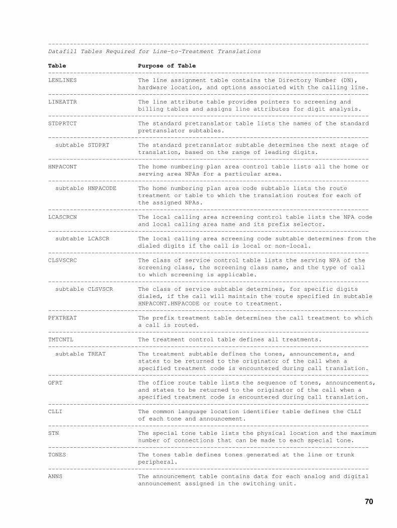
−−−−−−−−−−−−−−−−−−−−−−−−−−−−−−−−−−−−−−−−−−−−−−−−−−−−−−−−−−−−−−−−−−−−−−−−−−−−−−−−−−−−−−−−−Datafill Tables Required for Line−to−Treatment Translations
Table Purpose of Table−−−−−−−−−−−−−−−−−−−−−−−−−−−−−−−−−−−−−−−−−−−−−−−−−−−−−−−−−−−−−−−−−−−−−−−−−−−−−−−−−−−−−−−−−LENLINES The line assignment table contains the Directory Number (DN), hardware location, and options associated with the calling line.−−−−−−−−−−−−−−−−−−−−−−−−−−−−−−−−−−−−−−−−−−−−−−−−−−−−−−−−−−−−−−−−−−−−−−−−−−−−−−−−−−−−−−−−−LINEATTR The line attribute table provides pointers to screening and billing tables and assigns line attributes for digit analysis.−−−−−−−−−−−−−−−−−−−−−−−−−−−−−−−−−−−−−−−−−−−−−−−−−−−−−−−−−−−−−−−−−−−−−−−−−−−−−−−−−−−−−−−−−STDPRTCT The standard pretranslator table lists the names of the standard pretranslator subtables.−−−−−−−−−−−−−−−−−−−−−−−−−−−−−−−−−−−−−−−−−−−−−−−−−−−−−−−−−−−−−−−−−−−−−−−−−−−−−−−−−−−−−−−−− subtable STDPRT The standard pretranslator subtable determines the next stage of translation, based on the range of leading digits.−−−−−−−−−−−−−−−−−−−−−−−−−−−−−−−−−−−−−−−−−−−−−−−−−−−−−−−−−−−−−−−−−−−−−−−−−−−−−−−−−−−−−−−−−HNPACONT The home numbering plan area control table lists all the home or serving area NPAs for a particular area.−−−−−−−−−−−−−−−−−−−−−−−−−−−−−−−−−−−−−−−−−−−−−−−−−−−−−−−−−−−−−−−−−−−−−−−−−−−−−−−−−−−−−−−−− subtable HNPACODE The home numbering plan area code subtable lists the route treatment or table to which the translation routes for each of the assigned NPAs.−−−−−−−−−−−−−−−−−−−−−−−−−−−−−−−−−−−−−−−−−−−−−−−−−−−−−−−−−−−−−−−−−−−−−−−−−−−−−−−−−−−−−−−−−LCASCRCN The local calling area screening control table lists the NPA code and local calling area name and its prefix selector.−−−−−−−−−−−−−−−−−−−−−−−−−−−−−−−−−−−−−−−−−−−−−−−−−−−−−−−−−−−−−−−−−−−−−−−−−−−−−−−−−−−−−−−−− subtable LCASCR The local calling area screening code subtable determines from the dialed digits if the call is local or non−local.−−−−−−−−−−−−−−−−−−−−−−−−−−−−−−−−−−−−−−−−−−−−−−−−−−−−−−−−−−−−−−−−−−−−−−−−−−−−−−−−−−−−−−−−−CLSVSCRC The class of service control table lists the serving NPA of the screening class, the screening class name, and the type of call to which screening is applicable.−−−−−−−−−−−−−−−−−−−−−−−−−−−−−−−−−−−−−−−−−−−−−−−−−−−−−−−−−−−−−−−−−−−−−−−−−−−−−−−−−−−−−−−−− subtable CLSVSCR The class of service subtable determines, for specific digits dialed, if the call will maintain the route specified in subtable HNPACONT.HNPACODE or route to treatment.−−−−−−−−−−−−−−−−−−−−−−−−−−−−−−−−−−−−−−−−−−−−−−−−−−−−−−−−−−−−−−−−−−−−−−−−−−−−−−−−−−−−−−−−−PFXTREAT The prefix treatment table determines the call treatment to which a call is routed.−−−−−−−−−−−−−−−−−−−−−−−−−−−−−−−−−−−−−−−−−−−−−−−−−−−−−−−−−−−−−−−−−−−−−−−−−−−−−−−−−−−−−−−−−TMTCNTL The treatment control table defines all treatments.−−−−−−−−−−−−−−−−−−−−−−−−−−−−−−−−−−−−−−−−−−−−−−−−−−−−−−−−−−−−−−−−−−−−−−−−−−−−−−−−−−−−−−−−− subtable TREAT The treatment subtable defines the tones, announcements, and states to be returned to the originator of the call when a specified treatment code is encountered during call translation.−−−−−−−−−−−−−−−−−−−−−−−−−−−−−−−−−−−−−−−−−−−−−−−−−−−−−−−−−−−−−−−−−−−−−−−−−−−−−−−−−−−−−−−−−OFRT The office route table lists the sequence of tones, announcements, and states to be returned to the originator of the call when a specified treatment code is encountered during call translation.−−−−−−−−−−−−−−−−−−−−−−−−−−−−−−−−−−−−−−−−−−−−−−−−−−−−−−−−−−−−−−−−−−−−−−−−−−−−−−−−−−−−−−−−−CLLI The common language location identifier table defines the CLLI of each tone and announcement.−−−−−−−−−−−−−−−−−−−−−−−−−−−−−−−−−−−−−−−−−−−−−−−−−−−−−−−−−−−−−−−−−−−−−−−−−−−−−−−−−−−−−−−−−STN The special tone table lists the physical location and the maximum number of connections that can be made to each special tone.−−−−−−−−−−−−−−−−−−−−−−−−−−−−−−−−−−−−−−−−−−−−−−−−−−−−−−−−−−−−−−−−−−−−−−−−−−−−−−−−−−−−−−−−−TONES The tones table defines tones generated at the line or trunk peripheral.−−−−−−−−−−−−−−−−−−−−−−−−−−−−−−−−−−−−−−−−−−−−−−−−−−−−−−−−−−−−−−−−−−−−−−−−−−−−−−−−−−−−−−−−−ANNS The announcement table contains data for each analog and digital announcement assigned in the switching unit.
70

−−−−−−−−−−−−−−−−−−−−−−−−−−−−−−−−−−−−−−−−−−−−−−−−−−−−−−−−−−−−−−−−−−−−−−−−−−−−−−−−−−−−−−−−−ANNMEMS The announcement member table lists the assignments for each of the members assigned to the announcements listed in table ANNS.−−−−−−−−−−−−−−−−−−−−−−−−−−−−−−−−−−−−−−−−−−−−−−−−−−−−−−−−−−−−−−−−−−−−−−−−−−−−−−−−−−−−−−−−−−End−
Datafilling Table LENLINES
The following table shows the datafill specific to line−to−treatment translations for tableLENLINES. Only those fields that apply directly to line−to−treatment translations are shown:
−−−−−−−−−−−−−−−−−−−−−−−−−−−−−−−−−−−−−−−−−−−−−−−−−−−−−−−−−−−−−−−−−−−−−−−−−−−−−−−−−−−−−−−−−Datafilling Table LENLINES
Subfield orField Refinement Entry Explanation and Action−−−−−−−−−−−−−−−−−−−−−−−−−−−−−−−−−−−−−−−−−−−−−−−−−−−−−−−−−−−−−−−−−−−−−−−−−−−−−−−−−−−−−−−−−LEN See subfields Line Equipment Number This field defines the physical location of the equipment that is connected to a specific telephone line.
Note: Field LEN consists of subfields SITE, FRAME, UNIT, DRAWER or LSG, SHELF, SLOT, and CIRCUIT.−−−−−−−−−−−−−−−−−−−−−−−−−−−−−−−−−−−−−−−−−−−−−−−−−−−−−−−−−−−−−−−−−−−−−−−−−−−−−−−−−−−−−−−−−PTY R1 to R5, Party and Ringing Combination T1 to T5, or S If the line is assigned to a two−, four−, eight−, or ten−party line, enter the party, R1 to R5 or T1 to T5, of the DN assigned to the line. If the line is assigned to an individual line, enter "S" for single party.−−−−−−−−−−−−−−−−−−−−−−−−−−−−−−−−−−−−−−−−−−−−−−−−−−−−−−−−−−−−−−−−−−−−−−−−−−−−−−−−−−−−−−−−−LNATTIDX 0 to 31,999 Line Attribute Index Enter the index into table LINEATTR.−−−−−−−−−−−−−−−−−−−−−−−−−−−−−−−−−−−−−−−−−−−−−−−−−−−−−−−−−−−−−−−−−−−−−−−−−−−−−−−−−−−−−−−−−−End−
The following example MAP display shows sample datafill for table LENLINES:
LEN PTY RINGCODE DN SIGTYPE LNATTIDX OPTLIST_________________________________________________________HOST 02 0 05 08 R1 1 5703055 DT 71 $_________________________________________________________
Datafilling Table LINEATTR
The following table shows the datafill specific to line−to−treatment translations for tableLINEATTR. Only those fields that apply directly to line−to−treatment translations are shown:
−−−−−−−−−−−−−−−−−−−−−−−−−−−−−−−−−−−−−−−−−−−−−−−−−−−−−−−−−−−−−−−−−−−−−−−−−−−−−−−−−−−−−−−−−Datafilling Table LINEATTR
Subfield orField Refinement Entry Explanation and Action−−−−−−−−−−−−−−−−−−−−−−−−−−−−−−−−−−−−−−−−−−−−−−−−−−−−−−−−−−−−−−−−−−−−−−−−−−−−−−−−−−−−−−−−−LNATTIDX 0 to 31,999 Line Attribute Index Enter the index into table LINEATTR.−−−−−−−−−−−−−−−−−−−−−−−−−−−−−−−−−−−−−−−−−−−−−−−−−−−−−−−−−−−−−−−−−−−−−−−−−−−−−−−−−−−−−−−−−
71

SCRNCL Alphanumeric Class of Service Screening Subtable Name (up to 4 If screening by class of service is required, characters or enter the name of the class of service subtable NSCR) assigned to the line attribute index. If screening by class of service is not required, enter "NSCR".−−−−−−−−−−−−−−−−−−−−−−−−−−−−−−−−−−−−−−−−−−−−−−−−−−−−−−−−−−−−−−−−−−−−−−−−−−−−−−−−−−−−−−−−−STS Numeric Serving Translation Scheme (3 digits) Enter the SNPA assigned to the line attribute index. The STS of an existing tuple cannot be changed.−−−−−−−−−−−−−−−−−−−−−−−−−−−−−−−−−−−−−−−−−−−−−−−−−−−−−−−−−−−−−−−−−−−−−−−−−−−−−−−−−−−−−−−−−PRTNM Alphanumeric Standard Pretranslator Subtable Name (up to 4 If pretranslation of digits is required, characters or enter the name of the standard pretranslator NPRT) subtable assigned to the line attribute index. If standard pretranslation is not required, enter "NPRT".−−−−−−−−−−−−−−−−−−−−−−−−−−−−−−−−−−−−−−−−−−−−−−−−−−−−−−−−−−−−−−−−−−−−−−−−−−−−−−−−−−−−−−−−−LCANAME Alphanumeric Local Calling Area Screening Subtable Name (up to 4 If screening of local central office codes characters or (NNX) is required, enter the name of the local NLCA) calling area subtable assigned to the line attribute index. If screening of local NNX codes is not required, enter "NLCA".−−−−−−−−−−−−−−−−−−−−−−−−−−−−−−−−−−−−−−−−−−−−−−−−−−−−−−−−−−−−−−−−−−−−−−−−−−−−−−−−−−−−−−−−−−End−
The following example MAP display shows sample datafill for table LINEATTR:
LNATTIDX LCC CHGCLSS COST SCRNCL LTG STS PRTNM LCANAME ZEROMPOSTRAFSNO MRSA SFC LATANM MDI IXNAME DGCLNAME FANIDIGSRESINF OPTIONS________________________________________________________________________________________71 2FR NONE NT 807B 1 807 P570 P570 RTE310 NIL NILSFC NILLATA 0 NIL NIL 00N $________________________________________________________________________________________
Datafilling Table STDPRTCT
The following table shows the datafill specific to line−to−treatment translations for tableSTDPRTCT. Only those fields that apply directly to line−to−line translations are shown:
−−−−−−−−−−−−−−−−−−−−−−−−−−−−−−−−−−−−−−−−−−−−−−−−−−−−−−−−−−−−−−−−−−−−−−−−−−−−−−−−−−−−−−−−−Datafilling Table STDPRTCT
Subfield orField Refinement Entry Explanation and Action−−−−−−−−−−−−−−−−−−−−−−−−−−−−−−−−−−−−−−−−−−−−−−−−−−−−−−−−−−−−−−−−−−−−−−−−−−−−−−−−−−−−−−−−−EXPRTNM Alphanumeric External Standard Pretranslator Subtable Name (up to 8 Enter the name defined by the operating characters) company to represent the standard pre− translator.−−−−−−−−−−−−−−−−−−−−−−−−−−−−−−−−−−−−−−−−−−−−−−−−−−−−−−−−−−−−−−−−−−−−−−−−−−−−−−−−−−−−−−−−−STDPRT See note Standard Pretranslator The field is an index into subtable STDPRT.
Note: This field does not accept any input.−−−−−−−−−−−−−−−−−−−−−−−−−−−−−−−−−−−−−−−−−−−−−−−−−−−−−−−−−−−−−−−−−−−−−−−−−−−−−−−−−−−−−−−−−−End−
72

The following example MAP display shows sample datafill for table STDPRTCT:
EXPRTNM STDPRT AMAPRT_________________________________________________________P570 ( 1) (65021)_________________________________________________________
Datafilling Subtable STDPRTCT.STDPRT
The following table shows the datafill specific to line−to−treatment translations for subtableSTDPRTCT.STDPRT. Only those fields that apply directly to line−to−line translations are shown:
−−−−−−−−−−−−−−−−−−−−−−−−−−−−−−−−−−−−−−−−−−−−−−−−−−−−−−−−−−−−−−−−−−−−−−−−−−−−−−−−−−−−−−−−−Datafilling Subtable STDPRTCT.STDPRT
Subfield orField Refinement Entry Explanation and Action−−−−−−−−−−−−−−−−−−−−−−−−−−−−−−−−−−−−−−−−−−−−−−−−−−−−−−−−−−−−−−−−−−−−−−−−−−−−−−−−−−−−−−−−−FROMDIGS Numeric From Digits (up to 18 digits) Enter the digit or digits to be translated.
If the entry represents a block of consecutive numbers, enter the first number in the block.−−−−−−−−−−−−−−−−−−−−−−−−−−−−−−−−−−−−−−−−−−−−−−−−−−−−−−−−−−−−−−−−−−−−−−−−−−−−−−−−−−−−−−−−−TODIGS Numeric To Digits (up to 18 digits) If field FROMDIGS represents a block of consecutive numbers, enter the last number in the block.−−−−−−−−−−−−−−−−−−−−−−−−−−−−−−−−−−−−−−−−−−−−−−−−−−−−−−−−−−−−−−−−−−−−−−−−−−−−−−−−−−−−−−−−−PRETRTE See subfield Pretranslation Route This field consists of subfield PRERTSEL and its refinements TYPECALL, NOPREDIG, TRANSYS, and POS.
PRERTSEL D Pretranslator Route Selector Enter "D" to route directly to a treatment.
TREAT Alphanumeric Treatment (4 characters) Enter the treatment that is the route of the translation.−−−−−−−−−−−−−−−−−−−−−−−−−−−−−−−−−−−−−−−−−−−−−−−−−−−−−−−−−−−−−−−−−−−−−−−−−−−−−−−−−−−−−−−−−−End−
The following example MAP display shows sample datafill for subtable STDPRTCT.STDPRT:
FROMDIGS TODIGS PRETRTE_________________________________________________________8 910 D VACT_________________________________________________________
Datafilling Table HNPACONT
The following table shows the datafill specific to line−to−treatment translations for tableHNPACONT. Only those fields that apply directly to line−to−treatment translations are shown:
73

−−−−−−−−−−−−−−−−−−−−−−−−−−−−−−−−−−−−−−−−−−−−−−−−−−−−−−−−−−−−−−−−−−−−−−−−−−−−−−−−−−−−−−−−−Datafilling Table HNPACONT
Subfield orField Refinement Entry Explanation and Action−−−−−−−−−−−−−−−−−−−−−−−−−−−−−−−−−−−−−−−−−−−−−−−−−−−−−−−−−−−−−−−−−−−−−−−−−−−−−−−−−−−−−−−−−STS 0 to 9,999,999 Serving Numbering Plan Area Enter a Serving Numbering Plan Area (SNPA) or STS code.−−−−−−−−−−−−−−−−−−−−−−−−−−−−−−−−−−−−−−−−−−−−−−−−−−−−−−−−−−−−−−−−−−−−−−−−−−−−−−−−−−−−−−−−−HNPACODE Home Numbering Plan Area Code This field is an index into subtable HNPACODE.
Note: This field does not accept any input.−−−−−−−−−−−−−−−−−−−−−−−−−−−−−−−−−−−−−−−−−−−−−−−−−−−−−−−−−−−−−−−−−−−−−−−−−−−−−−−−−−−−−−−−−−End−
The following example MAP display shows sample datafill for table HNPACONT:
STS NORTREFS NOAMBIGC RTEREF HNPACODE ATTRIB RTEMAP_________________________________________________________418 128 0 ( 68) (1) (2) (0)_________________________________________________________
Datafilling Subtable HNPACONT.HNPACODE
The following table shows the datafill specific to line−to−treatment translations for subtableHNPACONT.HNPACODE. Only those fields that apply directly to line−to−treatment translations areshown:
−−−−−−−−−−−−−−−−−−−−−−−−−−−−−−−−−−−−−−−−−−−−−−−−−−−−−−−−−−−−−−−−−−−−−−−−−−−−−−−−−−−−−−−−−Datafilling Subtable HNPACONT.HNPACODE
Subfield orField Refinement Entry Explanation and Action−−−−−−−−−−−−−−−−−−−−−−−−−−−−−−−−−−−−−−−−−−−−−−−−−−−−−−−−−−−−−−−−−−−−−−−−−−−−−−−−−−−−−−−−−FROMDIGS Numeric From Digits (3 digits) Enter the number representing a single code or the first in a block of consecutive codes that have the same input data.−−−−−−−−−−−−−−−−−−−−−−−−−−−−−−−−−−−−−−−−−−−−−−−−−−−−−−−−−−−−−−−−−−−−−−−−−−−−−−−−−−−−−−−−−TODIGS Numeric To Digits (3 digits) If field FROMDIGS represents a single code, enter the same single code as in field FROMDIGS. If field FROMDIGS represents the first number of a block of consecutive numbers, enter the last number in the block.−−−−−−−−−−−−−−−−−−−−−−−−−−−−−−−−−−−−−−−−−−−−−−−−−−−−−−−−−−−−−−−−−−−−−−−−−−−−−−−−−−−−−−−−−CDRRTMT See subfield Code Type, Route Reference, or Treatment This field consists of subfield CD.
CD VCT Code Type Enter "VCT" to route a call to treatment specified in refinement TMT.
TMT Alphanumeric Treatment (up to 4 Enter the treatment that is used to index characters) subtable TMTCNTL.TREAT.−−−−−−−−−−−−−−−−−−−−−−−−−−−−−−−−−−−−−−−−−−−−−−−−−−−−−−−−−−−−−−−−−−−−−−−−−−−−−−−−−−−−−−−−−−End−
74

The following example MAP display shows sample datafill for subtable HNPACONT.HNPACODE:
FROMDIGS TODIGS CDRRTMT_________________________________________________________225 225 VCT BUSY_________________________________________________________
Datafilling Table LCASCRCN
The following table shows the datafill specific to line−to−treatment translations for tableLCASCRCN. Only those fields that apply directly to line−to−treatment translations are shown:
−−−−−−−−−−−−−−−−−−−−−−−−−−−−−−−−−−−−−−−−−−−−−−−−−−−−−−−−−−−−−−−−−−−−−−−−−−−−−−−−−−−−−−−−−Datafilling Table LCASCRCN
Subfield orField Refinement Entry Explanation and Action−−−−−−−−−−−−−−−−−−−−−−−−−−−−−−−−−−−−−−−−−−−−−−−−−−−−−−−−−−−−−−−−−−−−−−−−−−−−−−−−−−−−−−−−−NPALOCNM See subfields NPA Local Calling Area Subtable Name This field consists of subfields STS and LCANAME.−−−−−−−−−−−−−−−−−−−−−−−−−−−−−−−−−−−−−−−−−−−−−−−−−−−−−−−−−−−−−−−−−−−−−−−−−−−−−−−−−−−−−−−−− STS Numeric Serving Translation Scheme (3 digits) Enter an SNPA code for the trunk group.
LCANAME Alphanumeric Local Calling Area Name (up to 4 Enter the key to subtable LCASCRCN.LCASCR. characters)−−−−−−−−−−−−−−−−−−−−−−−−−−−−−−−−−−−−−−−−−−−−−−−−−−−−−−−−−−−−−−−−−−−−−−−−−−−−−−−−−−−−−−−−−LCASCR Local Calling Area Screening This field is an index into subtable LCASCR.
Note: This field does not accept any input.−−−−−−−−−−−−−−−−−−−−−−−−−−−−−−−−−−−−−−−−−−−−−−−−−−−−−−−−−−−−−−−−−−−−−−−−−−−−−−−−−−−−−−−−−PFXSELEC OPTL, MAND, Prefix Selector or Alphanumeric Enter the name of the prefix selector that (up to 4 is assigned to subtable LCASCR. characters)−−−−−−−−−−−−−−−−−−−−−−−−−−−−−−−−−−−−−−−−−−−−−−−−−−−−−−−−−−−−−−−−−−−−−−−−−−−−−−−−−−−−−−−−−−End−
The following example MAP display shows sample datafill for table LCASCRCN:
NPALOCNM LCASCR PFXSELEC PFSFOR10_________________________________________________________807 P570 ( 1) MAND N_________________________________________________________
Datafilling Subtable LCASCRCN.LCASCR
The following table shows the datafill specific to line−to−treatment translations for subtableLCASCRCN.LCASCR. Only those fields that apply directly to line−to−treatment translations areshown:
75

−−−−−−−−−−−−−−−−−−−−−−−−−−−−−−−−−−−−−−−−−−−−−−−−−−−−−−−−−−−−−−−−−−−−−−−−−−−−−−−−−−−−−−−−−Datafilling Subtable LCASCRCN.LCASCR
Subfield orField Refinement Entry Explanation and Action−−−−−−−−−−−−−−−−−−−−−−−−−−−−−−−−−−−−−−−−−−−−−−−−−−−−−−−−−−−−−−−−−−−−−−−−−−−−−−−−−−−−−−−−−FROMDIGS Numeric From Digits (3 digits) Enter the three−digit local NNX code to be screened. This number represents a single code or the first in a block of consecutive local NNX codes.−−−−−−−−−−−−−−−−−−−−−−−−−−−−−−−−−−−−−−−−−−−−−−−−−−−−−−−−−−−−−−−−−−−−−−−−−−−−−−−−−−−−−−−−−TODIGS Numeric To Digits (3 digits) If field FROMDIGS represents the first number of a block of consecutive local NNX codes, enter the last NNX code in the block to be screened. If field FROMDIGS represents a single local NNX code, enter the NNX code entered in FROMDIGS.−−−−−−−−−−−−−−−−−−−−−−−−−−−−−−−−−−−−−−−−−−−−−−−−−−−−−−−−−−−−−−−−−−−−−−−−−−−−−−−−−−−−−−−−−−End−
The following example MAP display shows sample datafill for table LCASCRCN.LCASCR:
FROMDIGS TODIGS________________________________570 570 ________________________________
Datafilling Table CLSVSCRC
The following table shows the datafill specific to line−to−treatment translations for tableCLSVSCRC. Only those fields that apply directly to line−to−treatment translations are shown:
−−−−−−−−−−−−−−−−−−−−−−−−−−−−−−−−−−−−−−−−−−−−−−−−−−−−−−−−−−−−−−−−−−−−−−−−−−−−−−−−−−−−−−−−−Datafilling Table CLSVSCRC
Subfield orField Refinement Entry Explanation and Action−−−−−−−−−−−−−−−−−−−−−−−−−−−−−−−−−−−−−−−−−−−−−−−−−−−−−−−−−−−−−−−−−−−−−−−−−−−−−−−−−−−−−−−−−NPASCTYP See subfields NPA Screening Class Type This field consists of subfields STS, SCRNCL, and TYPCALL.
STS Numeric Serving Translation Scheme (3 digits) Enter the SNPA for a given trunk group or line attribute.
SCRNCL Alphanumeric Screening Class (1 to 4 digits) Enter the class of service screening subtable name assigned to the trunk group, line attribute, or CAMA or AMR5 billing code.
TYPCALL DD, OA, NP, Type of Call or NL Enter the type of call, "DD" (Direct Dial), "OA" (Operator Assisted), "NP" (No Prefix), or "NL" (Nil).
For Traffic Operator Position System (TOPS) calls, there can be a mixture of 0 and 1 (OA and DD) call types. Enter "NL" for these cases.
76

−−−−−−−−−−−−−−−−−−−−−−−−−−−−−−−−−−−−−−−−−−−−−−−−−−−−−−−−−−−−−−−−−−−−−−−−−−−−−−−−−−−−−−−−−NORSLTS 0 to 255 Number of Results Enter the number of results required.−−−−−−−−−−−−−−−−−−−−−−−−−−−−−−−−−−−−−−−−−−−−−−−−−−−−−−−−−−−−−−−−−−−−−−−−−−−−−−−−−−−−−−−−−TMTOFRT See subfields Treatment or Office Route This field consists of subfields SCRNSEL and RTEREFIX.
SCRNSEL T or D Screening Selector Enter the screening selector "T" if translation routes to table OFRT. Datafill subfield RTEREFIX.
Enter the screening selector "D" if translation routes to one of the treatments in table TREAT. Datafill subfield TREAT.
RTEREFIX See subfields Route Reference Index This field consists of subfields OFC_RTE and RTE_ID.
OFC_RTE OFRT, OFR2, Office Route Table Name OFR3, OFR4 Enter the office route table name to which the translations are directed.
RTE_ID 0 to 1,023 Route Reference Table Index Enter the route index in table OFRT to which the translation routes.
TREAT Alphanumeric Treatment (up to 4 Enter the treatment in table TREAT to which characters) translation routes.−−−−−−−−−−−−−−−−−−−−−−−−−−−−−−−−−−−−−−−−−−−−−−−−−−−−−−−−−−−−−−−−−−−−−−−−−−−−−−−−−−−−−−−−−−End−
The following example MAP display shows sample datafill for table CLSVSCRC:
NPASCTYP NORSLTS TMTOFRT CLSVSC_________________________________________________________418 P225 NP 2 D BUSY (0)_________________________________________________________
Datafilling Subtable CLSVSCRC.CLSVSCR
The following table shows the datafill specific to line−to−treatment translations for subtableCLSVSCRC.CLSVSCR. Only those fields that apply directly to line−to−treatment translations areshown:
−−−−−−−−−−−−−−−−−−−−−−−−−−−−−−−−−−−−−−−−−−−−−−−−−−−−−−−−−−−−−−−−−−−−−−−−−−−−−−−−−−−−−−−−−Datafilling Subtable CLSVSCRC.CLSVSCR
Subfield orField Refinement Entry Explanation and Action−−−−−−−−−−−−−−−−−−−−−−−−−−−−−−−−−−−−−−−−−−−−−−−−−−−−−−−−−−−−−−−−−−−−−−−−−−−−−−−−−−−−−−−−−FROMDIGS Numeric From Digits (up to 18 Enter the single code or the first in a digits) block of consecutive codes that have the same screening route.
77
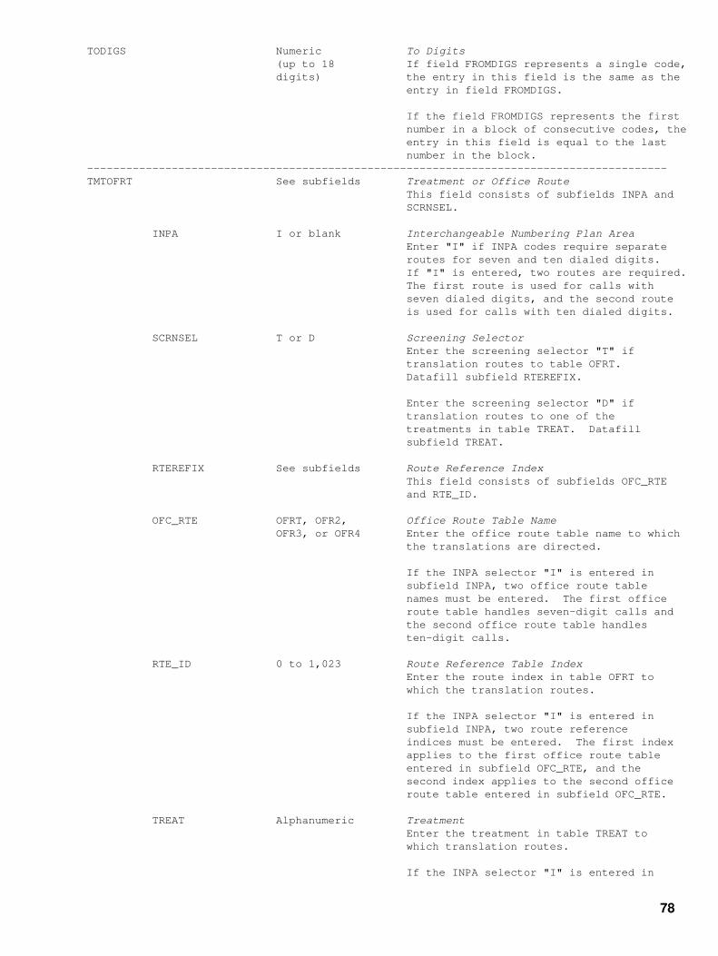
TODIGS Numeric To Digits (up to 18 If field FROMDIGS represents a single code, digits) the entry in this field is the same as the entry in field FROMDIGS.
If the field FROMDIGS represents the first number in a block of consecutive codes, the entry in this field is equal to the last number in the block.−−−−−−−−−−−−−−−−−−−−−−−−−−−−−−−−−−−−−−−−−−−−−−−−−−−−−−−−−−−−−−−−−−−−−−−−−−−−−−−−−−−−−−−−−TMTOFRT See subfields Treatment or Office Route This field consists of subfields INPA and SCRNSEL.
INPA I or blank Interchangeable Numbering Plan Area Enter "I" if INPA codes require separate routes for seven and ten dialed digits. If "I" is entered, two routes are required. The first route is used for calls with seven dialed digits, and the second route is used for calls with ten dialed digits.
SCRNSEL T or D Screening Selector Enter the screening selector "T" if translation routes to table OFRT. Datafill subfield RTEREFIX.
Enter the screening selector "D" if translation routes to one of the treatments in table TREAT. Datafill subfield TREAT.
RTEREFIX See subfields Route Reference Index This field consists of subfields OFC_RTE and RTE_ID.
OFC_RTE OFRT, OFR2, Office Route Table Name OFR3, or OFR4 Enter the office route table name to which the translations are directed.
If the INPA selector "I" is entered in subfield INPA, two office route table names must be entered. The first office route table handles seven−digit calls and the second office route table handles ten−digit calls.
RTE_ID 0 to 1,023 Route Reference Table Index Enter the route index in table OFRT to which the translation routes.
If the INPA selector "I" is entered in subfield INPA, two route reference indices must be entered. The first index applies to the first office route table entered in subfield OFC_RTE, and the second index applies to the second office route table entered in subfield OFC_RTE.
TREAT Alphanumeric Treatment Enter the treatment in table TREAT to which translation routes.
If the INPA selector "I" is entered in
78

subfield INPA, two treatments must be entered. The first treatment handles seven−digit calls, and the second treatment handles ten−digit calls.−−−−−−−−−−−−−−−−−−−−−−−−−−−−−−−−−−−−−−−−−−−−−−−−−−−−−−−−−−−−−−−−−−−−−−−−−−−−−−−−−−−−−−−−−−End−
The following example MAP display shows sample datafill for subtable CLSVSCRC.CLSVSCR:
FROMDIGS TODIGS TMTOFRT_________________________________________________________344 345 D VACT_________________________________________________________
Datafilling Table PFXTREAT
The following table shows the datafill specific to line−to−treatment translations for tablePFXTREAT. Only those fields that apply directly to line−to−treatment translations are shown:
−−−−−−−−−−−−−−−−−−−−−−−−−−−−−−−−−−−−−−−−−−−−−−−−−−−−−−−−−−−−−−−−−−−−−−−−−−−−−−−−−−−−−−−−−Datafilling Table PFXTREAT
Subfield orField Refinement Entry Explanation and Action−−−−−−−−−−−−−−−−−−−−−−−−−−−−−−−−−−−−−−−−−−−−−−−−−−−−−−−−−−−−−−−−−−−−−−−−−−−−−−−−−−−−−−−−−TYPLCLCD See subfields Type of Call and Local Code This field consists of subfields PFXSELEC and TYPCALL.
PFXSELEC OPTL, MAND, Prefix Selector or Alphanumeric Enter the prefix selector assigned to (up to 4 the prefix treatment. characters)
TYPCALL DD, NP, OA, Type of Call or NL Enter either "DD" (Direct Dial), "NP" (No Prefix), "OA" (Operator Assisted), or "NL" (Nil) for the type of call.
For Traffic Operator Position System (TOPS) calls, there can be a mixture of 0 and 1 (OA and DD) call types. Enter "NL" for these cases.−−−−−−−−−−−−−−−−−−−−−−−−−−−−−−−−−−−−−−−−−−−−−−−−−−−−−−−−−−−−−−−−−−−−−−−−−−−−−−−−−−−−−−−−−TREAT Alphanumeric Treatment (up to 4 Enter the treatment that is the route of characters) the translation.−−−−−−−−−−−−−−−−−−−−−−−−−−−−−−−−−−−−−−−−−−−−−−−−−−−−−−−−−−−−−−−−−−−−−−−−−−−−−−−−−−−−−−−−−−End−
The following example MAP display shows sample datafill for table PFXTREAT:
TYPLCLCD UPDTYPCA TREAT_________________________________________________________MAND DD N DD UNDT_________________________________________________________
79
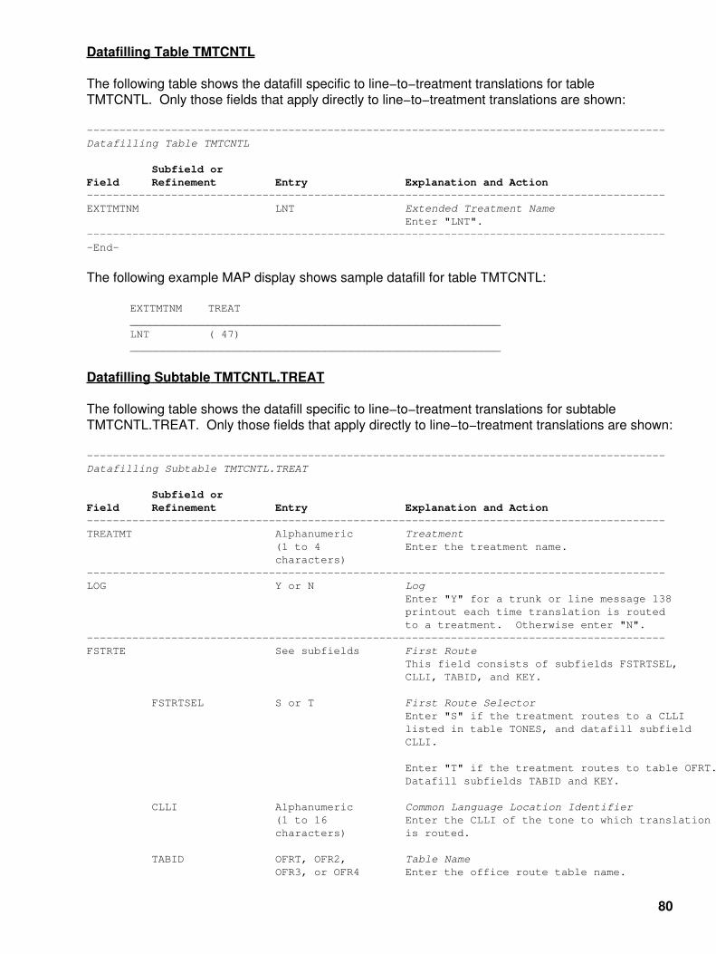
Datafilling Table TMTCNTL
The following table shows the datafill specific to line−to−treatment translations for tableTMTCNTL. Only those fields that apply directly to line−to−treatment translations are shown:
−−−−−−−−−−−−−−−−−−−−−−−−−−−−−−−−−−−−−−−−−−−−−−−−−−−−−−−−−−−−−−−−−−−−−−−−−−−−−−−−−−−−−−−−−Datafilling Table TMTCNTL
Subfield orField Refinement Entry Explanation and Action−−−−−−−−−−−−−−−−−−−−−−−−−−−−−−−−−−−−−−−−−−−−−−−−−−−−−−−−−−−−−−−−−−−−−−−−−−−−−−−−−−−−−−−−−EXTTMTNM LNT Extended Treatment Name Enter "LNT".−−−−−−−−−−−−−−−−−−−−−−−−−−−−−−−−−−−−−−−−−−−−−−−−−−−−−−−−−−−−−−−−−−−−−−−−−−−−−−−−−−−−−−−−−−End−
The following example MAP display shows sample datafill for table TMTCNTL:
EXTTMTNM TREAT_________________________________________________________LNT ( 47)_________________________________________________________
Datafilling Subtable TMTCNTL.TREAT
The following table shows the datafill specific to line−to−treatment translations for subtableTMTCNTL.TREAT. Only those fields that apply directly to line−to−treatment translations are shown:
−−−−−−−−−−−−−−−−−−−−−−−−−−−−−−−−−−−−−−−−−−−−−−−−−−−−−−−−−−−−−−−−−−−−−−−−−−−−−−−−−−−−−−−−−Datafilling Subtable TMTCNTL.TREAT
Subfield orField Refinement Entry Explanation and Action−−−−−−−−−−−−−−−−−−−−−−−−−−−−−−−−−−−−−−−−−−−−−−−−−−−−−−−−−−−−−−−−−−−−−−−−−−−−−−−−−−−−−−−−−TREATMT Alphanumeric Treatment (1 to 4 Enter the treatment name. characters)−−−−−−−−−−−−−−−−−−−−−−−−−−−−−−−−−−−−−−−−−−−−−−−−−−−−−−−−−−−−−−−−−−−−−−−−−−−−−−−−−−−−−−−−−LOG Y or N Log Enter "Y" for a trunk or line message 138 printout each time translation is routed to a treatment. Otherwise enter "N".−−−−−−−−−−−−−−−−−−−−−−−−−−−−−−−−−−−−−−−−−−−−−−−−−−−−−−−−−−−−−−−−−−−−−−−−−−−−−−−−−−−−−−−−−FSTRTE See subfields First Route This field consists of subfields FSTRTSEL, CLLI, TABID, and KEY.
FSTRTSEL S or T First Route Selector Enter "S" if the treatment routes to a CLLI listed in table TONES, and datafill subfield CLLI.
Enter "T" if the treatment routes to table OFRT. Datafill subfields TABID and KEY.
CLLI Alphanumeric Common Language Location Identifier (1 to 16 Enter the CLLI of the tone to which translation characters) is routed.
TABID OFRT, OFR2, Table Name OFR3, or OFR4 Enter the office route table name.
80

KEY 1 to 1,023 Key Enter the index into the office route table that defines the route list for the treatment.−−−−−−−−−−−−−−−−−−−−−−−−−−−−−−−−−−−−−−−−−−−−−−−−−−−−−−−−−−−−−−−−−−−−−−−−−−−−−−−−−−−−−−−−−−End−
The following example MAP displays shows sample datafill for subtable TMTCNTL.TREAT. In thefirst tuple, the call routes to table OFRT. In the second tuple, the call routes to a tone:
Note: The SCATMT must be added to tables ANNS and ANNMEMS beforedatafilling table TMTCNTL (Treatment Control) and its subtables LNT andOFFTREAT.
TREATMT LOG FSTRTE_________________________________________________________VACT Y T OFRT 66_________________________________________________________
Datafilling Table OFRT
The following table shows the datafill specific to line−to−treatment translations for table OFRT. Onlythose fields that apply directly to line−to−treatment translations are shown:
−−−−−−−−−−−−−−−−−−−−−−−−−−−−−−−−−−−−−−−−−−−−−−−−−−−−−−−−−−−−−−−−−−−−−−−−−−−−−−−−−−−−−−−−−Datafilling Table OFRT
Subfield orField Refinement Entry Explanation and Action−−−−−−−−−−−−−−−−−−−−−−−−−−−−−−−−−−−−−−−−−−−−−−−−−−−−−−−−−−−−−−−−−−−−−−−−−−−−−−−−−−−−−−−−−RTE 1 to 1,023 Route Reference Index Enter the route reference number assigned to the route list.−−−−−−−−−−−−−−−−−−−−−−−−−−−−−−−−−−−−−−−−−−−−−−−−−−−−−−−−−−−−−−−−−−−−−−−−−−−−−−−−−−−−−−−−−RTELIST See subfield Route List This field consists of subfield RTESEL and refinements RTESEL, CONNTYPE, CLLI, and ROUTATTR_INDEX. Enter "$" to signify the end of the vector.
RTESEL S or SX Route Selector Enter "S" for standard and datafill refinements CONNTYPE and CLLI.
Enter "SX" for expanded standard and datafill refinements CLLI and ROUTATTR_INDEX.
CONNTYPE D Connection Type This field is not used by system logic. Enter "D" to satisfy table control.
CLLI Alphanumeric Common Language Location Identifier (1 to 16 Enter the code in table CLLI to which characters) translation is routed.
ROUTATTR_INDEX Alphanumeric Route Attribute Index (1 to 16 Enter the index in table ROUTATTR that contains characters) the expanded routing information to be applied.−−−−−−−−−−−−−−−−−−−−−−−−−−−−−−−−−−−−−−−−−−−−−−−−−−−−−−−−−−−−−−−−−−−−−−−−−−−−−−−−−−−−−−−−−−End−
81

The following example MAP display shows sample datafill for table OFRT:
RTE RTELIST_________________________________________________________66 (S D VCA) (S D *OFLO) (S D LKOUT) $_________________________________________________________
Datafilling Table CLLI
The following table shows the datafill specific to line−to−treatment translations for table CLLI. Onlythose fields that apply directly to line−to−treatment translations are shown:
−−−−−−−−−−−−−−−−−−−−−−−−−−−−−−−−−−−−−−−−−−−−−−−−−−−−−−−−−−−−−−−−−−−−−−−−−−−−−−−−−−−−−−−−−Datafilling Table CLLI
Subfield orField Refinement Entry Explanation and Action−−−−−−−−−−−−−−−−−−−−−−−−−−−−−−−−−−−−−−−−−−−−−−−−−−−−−−−−−−−−−−−−−−−−−−−−−−−−−−−−−−−−−−−−−CLLI Alphanumeric Common Language Location Identifier (1 to 16 Enter a CLLI code to uniquely identify the characters) far end of each announcement, tone, or trunk group.−−−−−−−−−−−−−−−−−−−−−−−−−−−−−−−−−−−−−−−−−−−−−−−−−−−−−−−−−−−−−−−−−−−−−−−−−−−−−−−−−−−−−−−−−−End−
The following example MAP display shows sample datafill for table CLLI:
CLLI ADNUM TRKGRSIZ ADMININF_________________________________________________________VCA 94 10 XX BUSY 149 0 BUSY_TONE_________________________________________________________
Datafilling Table STN
The following table shows the datafill specific to line−to−treatment translations for table STN. Onlythose fields that apply directly to line−to−treatment translations are shown:
−−−−−−−−−−−−−−−−−−−−−−−−−−−−−−−−−−−−−−−−−−−−−−−−−−−−−−−−−−−−−−−−−−−−−−−−−−−−−−−−−−−−−−−−−Datafilling Table STN
Subfield orField Refinement Entry Explanation and Action−−−−−−−−−−−−−−−−−−−−−−−−−−−−−−−−−−−−−−−−−−−−−−−−−−−−−−−−−−−−−−−−−−−−−−−−−−−−−−−−−−−−−−−−−SK See subfields Special Tone Key This field consists of subfields TONE and MEMBER.
TONE Alphanumeric Tone (1 to 16 Enter the fixed code (TONE_INDEX) assigned to characters) the tone trunk circuit in table CLLI.
MEMBER 0 to 999 Member Number Enter the tone trunk circuit member number.−−−−−−−−−−−−−−−−−−−−−−−−−−−−−−−−−−−−−−−−−−−−−−−−−−−−−−−−−−−−−−−−−−−−−−−−−−−−−−−−−−−−−−−−−MAXCONN 0 to 255 Maximum Connections Enter the maximum number of simultaneous connections that are allowed to be made to the tone trunk circuit.−−−−−−−−−−−−−−−−−−−−−−−−−−−−−−−−−−−−−−−−−−−−−−−−−−−−−−−−−−−−−−−−−−−−−−−−−−−−−−−−−−−−−−−−−−End−
82
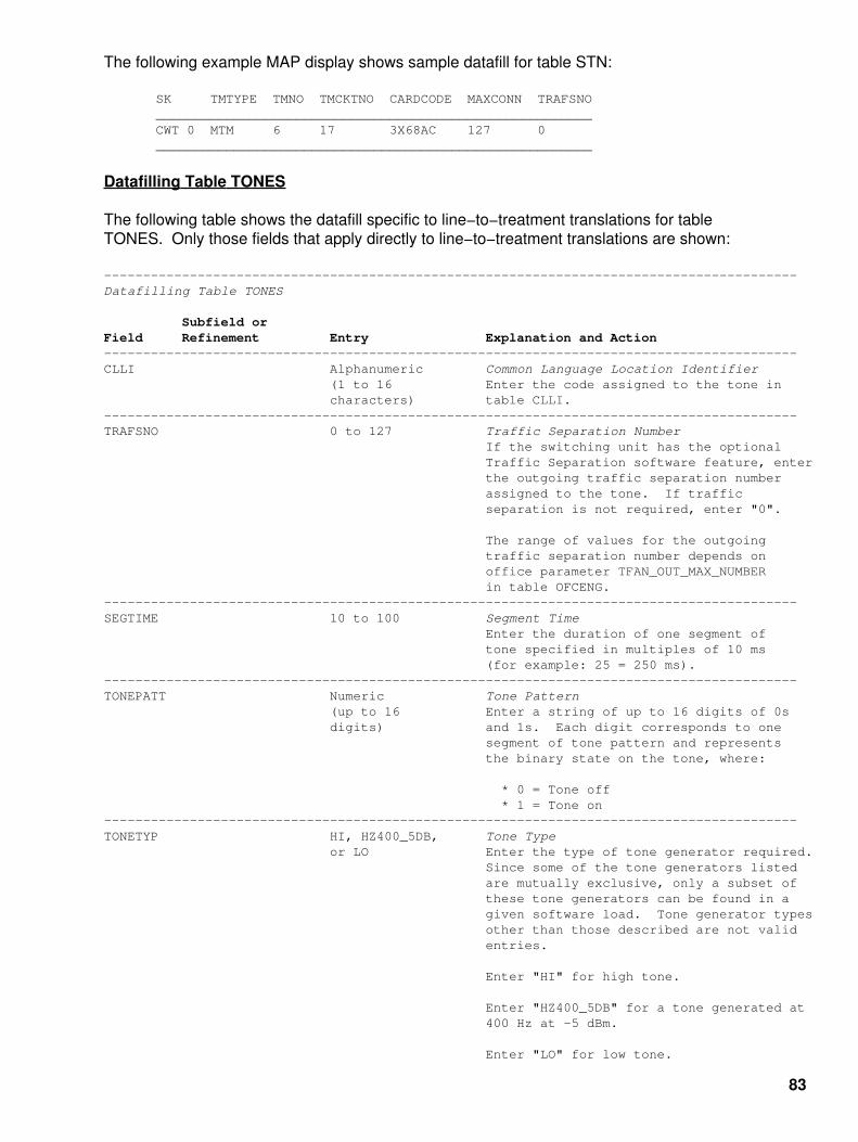
The following example MAP display shows sample datafill for table STN:
SK TMTYPE TMNO TMCKTNO CARDCODE MAXCONN TRAFSNO________________________________________________________CWT 0 MTM 6 17 3X68AC 127 0________________________________________________________
Datafilling Table TONES
The following table shows the datafill specific to line−to−treatment translations for tableTONES. Only those fields that apply directly to line−to−treatment translations are shown:
−−−−−−−−−−−−−−−−−−−−−−−−−−−−−−−−−−−−−−−−−−−−−−−−−−−−−−−−−−−−−−−−−−−−−−−−−−−−−−−−−−−−−−−−−Datafilling Table TONES
Subfield orField Refinement Entry Explanation and Action−−−−−−−−−−−−−−−−−−−−−−−−−−−−−−−−−−−−−−−−−−−−−−−−−−−−−−−−−−−−−−−−−−−−−−−−−−−−−−−−−−−−−−−−−CLLI Alphanumeric Common Language Location Identifier (1 to 16 Enter the code assigned to the tone in characters) table CLLI.−−−−−−−−−−−−−−−−−−−−−−−−−−−−−−−−−−−−−−−−−−−−−−−−−−−−−−−−−−−−−−−−−−−−−−−−−−−−−−−−−−−−−−−−−TRAFSNO 0 to 127 Traffic Separation Number If the switching unit has the optional Traffic Separation software feature, enter the outgoing traffic separation number assigned to the tone. If traffic separation is not required, enter "0".
The range of values for the outgoing traffic separation number depends on office parameter TFAN_OUT_MAX_NUMBER in table OFCENG.−−−−−−−−−−−−−−−−−−−−−−−−−−−−−−−−−−−−−−−−−−−−−−−−−−−−−−−−−−−−−−−−−−−−−−−−−−−−−−−−−−−−−−−−−SEGTIME 10 to 100 Segment Time Enter the duration of one segment of tone specified in multiples of 10 ms (for example: 25 = 250 ms).−−−−−−−−−−−−−−−−−−−−−−−−−−−−−−−−−−−−−−−−−−−−−−−−−−−−−−−−−−−−−−−−−−−−−−−−−−−−−−−−−−−−−−−−−TONEPATT Numeric Tone Pattern (up to 16 Enter a string of up to 16 digits of 0s digits) and 1s. Each digit corresponds to one segment of tone pattern and represents the binary state on the tone, where:
* 0 = Tone off * 1 = Tone on−−−−−−−−−−−−−−−−−−−−−−−−−−−−−−−−−−−−−−−−−−−−−−−−−−−−−−−−−−−−−−−−−−−−−−−−−−−−−−−−−−−−−−−−−TONETYP HI, HZ400_5DB, Tone Type or LO Enter the type of tone generator required. Since some of the tone generators listed are mutually exclusive, only a subset of these tone generators can be found in a given software load. Tone generator types other than those described are not valid entries.
Enter "HI" for high tone.
Enter "HZ400_5DB" for a tone generated at 400 Hz at −5 dBm.
Enter "LO" for low tone.
83

−−−−−−−−−−−−−−−−−−−−−−−−−−−−−−−−−−−−−−−−−−−−−−−−−−−−−−−−−−−−−−−−−−−−−−−−−−−−−−−−−−−−−−−−−MAXDURN 1 to 255 Maximum Duration Enter the maximum time in seconds that a call condense block can be attached.
The maximum time duration for silent tone is 10 seconds.−−−−−−−−−−−−−−−−−−−−−−−−−−−−−−−−−−−−−−−−−−−−−−−−−−−−−−−−−−−−−−−−−−−−−−−−−−−−−−−−−−−−−−−−−−End−
The following example MAP display shows sample datafill for table TONES:
CLLI TRAFSNO SEGTIME TONEPATT TONETYP MAXDURN MAXCONN____________________________________________________________*BUSY 21 50 101010 LO 40 30____________________________________________________________
Datafilling Table ANNS
The following table shows the datafill specific to line−to−treatment translations for tableANNS. Only those fields that apply directly to line−to−treatment translations are shown:
−−−−−−−−−−−−−−−−−−−−−−−−−−−−−−−−−−−−−−−−−−−−−−−−−−−−−−−−−−−−−−−−−−−−−−−−−−−−−−−−−−−−−−−−−Datafilling Table ANNS
Subfield orField Refinement Entry Explanation and Action−−−−−−−−−−−−−−−−−−−−−−−−−−−−−−−−−−−−−−−−−−−−−−−−−−−−−−−−−−−−−−−−−−−−−−−−−−−−−−−−−−−−−−−−−CLLI Alphanumeric Common Language Location Identifier (1 to 16 Enter the code assigned to the tone in characters) table CLLI.−−−−−−−−−−−−−−−−−−−−−−−−−−−−−−−−−−−−−−−−−−−−−−−−−−−−−−−−−−−−−−−−−−−−−−−−−−−−−−−−−−−−−−−−−ANTYPE ACTS, AIN, AIS, Announcement Type AOSSVR, CFRA, Enter the announcement type as follows: CLASS, CNAL, CNALT, CNAT, * ACTS for Automatic Coin Toll Service. DMCT, MCCS, NFRA, SLEENG, * AIN for a given DMS−100 switch user SLEFRE, SPP, interface for each customer group. STND, SACB, or TOPSVR * AIS for Automatic Intercept System announcement if the switch has the AIS feature.
* AOSSVR for AOSS Voice Response.
* CFRA for Call Forwarding Remote Access announcement.
* CLASS for Custom Local Area Signaling Services announcement.
* CNAL for Calling Number Announcement playback to a line.
* CNALT for Calling Number Announcement playback to a line and over a trunk to a loudspeaker.
* CNAT for Calling Number Announcement playback over a trunk to a loudspeaker.
84

* DMCT for Denied Malicious Call Termination.
* MCCS for Mechanized Calling Card announcement.
* NFRA for Network facility Remote Access.
* SLEENG for Screening List Editing English.
* SLEFRE for Screening List Editing French.
* SPP for Station Programmable PIN (Personal Identification Number).
* STND for Standard announcement.
* SACB for Subscriber Activated Call Blocking.
* TOPSVR for TOPS Voice Response.
Note: Office parameter TOPS_ACTS must be set to "Y" in table OFCENG.−−−−−−−−−−−−−−−−−−−−−−−−−−−−−−−−−−−−−−−−−−−−−−−−−−−−−−−−−−−−−−−−−−−−−−−−−−−−−−−−−−−−−−−−−MAXCONN 1 to 255 Maximum Connections Enter the maximum number of simultaneous connections that are permitted on the announcement.−−−−−−−−−−−−−−−−−−−−−−−−−−−−−−−−−−−−−−−−−−−−−−−−−−−−−−−−−−−−−−−−−−−−−−−−−−−−−−−−−−−−−−−−−CYTIME 1 to 18 or 0 Cycle Times Enter the time, in seconds, for one announcement cycle on one channel.
Note 1: If your office is equipped with a Cook or equivalent announcement machine and table AUDIO is datafilled as ANNS, field CYTIME is changed to 0. This allows flexible announcement timing.
Note 2: The cycle time for an Audichron is 0 due to the variable length announcement feature on Audichron. By setting the value of this field to 0, the length of the announcement is always matched.−−−−−−−−−−−−−−−−−−−−−−−−−−−−−−−−−−−−−−−−−−−−−−−−−−−−−−−−−−−−−−−−−−−−−−−−−−−−−−−−−−−−−−−−−MAXCYC 1 to 255 Maximum Cycles Enter the maximum number of times the complete announcement is heard before the call is advanced to the next route in the route list.−−−−−−−−−−−−−−−−−−−−−−−−−−−−−−−−−−−−−−−−−−−−−−−−−−−−−−−−−−−−−−−−−−−−−−−−−−−−−−−−−−−−−−−−−−End−
The following example MAP display shows sample datafill for table ANNS:
CLLI ANTYPE TRAFSNO MAXCONN CYTIME MAXCYC____________________________________________________________VCA STND 25 30 14 1____________________________________________________________
85

Datafilling Table ANNSMEMS
The following table shows the datafill specific to line−to−treatment translations for tableANNMEMS. Only those fields that apply directly to line−to−treatment translations are shown:
−−−−−−−−−−−−−−−−−−−−−−−−−−−−−−−−−−−−−−−−−−−−−−−−−−−−−−−−−−−−−−−−−−−−−−−−−−−−−−−−−−−−−−−−−Datafilling Table ANNSMEMS
Subfield orField Refinement Entry Explanation and Action−−−−−−−−−−−−−−−−−−−−−−−−−−−−−−−−−−−−−−−−−−−−−−−−−−−−−−−−−−−−−−−−−−−−−−−−−−−−−−−−−−−−−−−−−ANNMEM See subfields Announcement Member Key This field consists of subfields ANN and MEMBER.
ANN Alphanumeric Announcement (1 to 16 Enter the code that represents the characters) announcement group in table CLLI.
MEMBER 0 to 255 Member If the trunk circuit is the first in the trunk list for the announcement member, enter the number assigned to the member.
If digital, each announcement member can be assigned up to eight trunk circuits.
If analog, each announcement can be assigned up to two trunk circuits.−−−−−−−−−−−−−−−−−−−−−−−−−−−−−−−−−−−−−−−−−−−−−−−−−−−−−−−−−−−−−−−−−−−−−−−−−−−−−−−−−−−−−−−−−HDWTYPE AUDICHRON Hardware Type or DRAM Enter "AUDICHRON" if the first entry for the member and hardware type is analog.
Enter "DRAM" if the recorded announcement member is digital.−−−−−−−−−−−−−−−−−−−−−−−−−−−−−−−−−−−−−−−−−−−−−−−−−−−−−−−−−−−−−−−−−−−−−−−−−−−−−−−−−−−−−−−−−−End−
The following example MAP display shows sample datafill for table ANNSMEMS:
ANNMEM HDWTYPE CARD MEMINFO____________________________________________________________VCA 0 DRAM DRA (0 MTM 2 4) $____________________________________________________________
Translation Verification Tools
The following example shows the output from the TRAVER command when it is used to verifyline−to−treatment translations between DNs (807) 570−3055 to (819) 450−6666:
−−−−−−−−−−−−−−−−−−−−−−−−−−−−−−−−−−−−−−−−−−−−−−−−−−−−−−−−−−−−−−−−−−−−−−−−−−−−−−−−−−−−−−−−−>TRAVER l 5703055 8194506666 bTABLE LINEATTR71 2FR NONE NT 807B 1 807 P570 P570 RTE3 10 NIL NILSFC NILLATA 0 NIL NIL 00 N $LCABILL OFF − BILLING DONE ON BASIS OF CALLTYPETABLE DNATTRSTUPLE NOT FOUNDTABLE DNGRPSTUPLE NOT FOUNDOriginator is not an AIN agent, therefore AIN info is not processed.
86

TABLE STDPRTCTP570 ( 1) (65021) 0 . SUBTABLE STDPRTWARNING: CHANGES IN TABLE STDPRT MAY ALTER OFFICE BILLING. CALL TYPE DEFAULT IS NP. PLEASE REFER TO DOCUMENTATION. . 8 910 D VACT . SUBTABLE AMAPRT . KEY NOT FOUND . DEFAULT VALUE IS: NONE OVRNONE NTABLE TMTCNTLLNT ( 47) . SUBTABLE TREAT . VACT Y T OFRT 66 . TABLE OFRT . 66 S D VCA . S D *OFLO . S D LKOUT . EXIT TABLE OFRT
+++ TRAVER: SUCCESSFUL CALL TRACE +++
TREATMENT ROUTES. TREATMENT IS: VACT1 VCA2 *OFLO3 LKOUT
+++ TRAVER: SUCCESSFUL CALL TRACE +++−−−−−−−−−−−−−−−−−−−−−−−−−−−−−−−−−−−−−−−−−−−−−−−−−−−−−−−−−−−−−−−−−−−−−−−−−−−−−−−−−−−−−−−−−−End−
87

Nortel DMS−100 Command Screening Table (CMDS)
Table Name
Command Screening Table.
Functional Description of Table CMDS
Command screening table CMDS is part of the enhanced security feature. Office parameterENHANCED_COMMAND_SCREENING, in table OFCOPT (Office Options), determines if thefeature is active. You set office parameter ENHANCED_COMMAND_SCREENING to Y if youpurchased the feature or N if you did not purchase the feature. You cannot set office parameterENHANCED_COMMAND_SCREENING after the first datafill. This prevention stops any personfrom overriding security.
Each command that has between one and thirty−one command classes appears in table CMDS.
You can assign any set of up to 31 classes to a command. For more information, refer to thedescription of table TERMDEV (Terminal Devices) in the data schema section of TranslationsGuide. Command screening ensures that the command classes of the user match the classes ofthe commands the user wants to use. You must datafill each command for the directory in whichyou intend to use the command. For example, if you want the Force Release (FRLS) command tobe accessible at the Line Test Position (LTP) level of the Maintenance and Administration Position(MAP), you must make a FRLS entry in table CMDS for the LTP directory.
The PRIVCLAS command allows multiple command classes to be set.
Fields LOGONUSE, USEALARM, LOGABUSE, and ALRMABUS determine if the system generatesa log or alarm for command use or abuse.
The system automatically inserts tuples in this table with default values.
Datafill Sequence
You do not need to enter data in other tables before you enter data in table CMDS.
Table Size
The system dynamically allocates memory for this table. The initial size of the table is 100entries. The system automatically expands the table size when necessary.
Datafill
The following table describes datafill for table CMDS:
88

−−−−−−−−−−−−−−−−−−−−−−−−−−−−−−−−−−−−−−−−−−−−−−−−−−−−−−−−−−−−−−−−−−−−−−−−−−−−−−−−−−−−−−−−−Field Descriptions
Field Subfield Entry Explanation and Action−−−−−−−−−−−−−−−−−−−−−−−−−−−−−−−−−−−−−−−−−−−−−−−−−−−−−−−−−−−−−−−−−−−−−−−−−−−−−−−−−−−−−−−−CMDINCR See subfields Command and Increment.
This field has the subfields CMDNAME and INCRNAME.
CMDNAME Alphanumeric Command Name. (1 to 16 Enter the command name. characters)
INCRNAME Alphanumeric Increment Name. (1 to 16 Enter the increment name. characters) or If the command is not part of an increment, $ enter "$".−−−−−−−−−−−−−−−−−−−−−−−−−−−−−−−−−−−−−−−−−−−−−−−−−−−−−−−−−−−−−−−−−−−−−−−−−−−−−−−−−−−−−−−−DUMPSAFE NOTSAFE, DSPS, Command Availability. or PS The default value NOTSAFE makes the command not available during Data Store (DS) dump and Program Store (PS) dump.
Enter "DSPS" if you want the command available during both DS dump and PS dump.
Enter "PS" if want want the command available only during PS (after DS is complete).−−−−−−−−−−−−−−−−−−−−−−−−−−−−−−−−−−−−−−−−−−−−−−−−−−−−−−−−−−−−−−−−−−−−−−−−−−−−−−−−−−−−−−−−LOGONUSE Y or N Command Use Log Status. Enter "Y" if you want a log report for each use of the command. Enter "N" if you do not want a log report for each use of the command.
The default value is "N".−−−−−−−−−−−−−−−−−−−−−−−−−−−−−−−−−−−−−−−−−−−−−−−−−−−−−−−−−−−−−−−−−−−−−−−−−−−−−−−−−−−−−−−−USEALARM CR, MJ, MN, Command Use Alarm Status. or NA Enter one of the following values:
* CR if you want a critical alarm for command use.
* MJ if you want a major alarm for command use.
* MN if you want a minor alarm for command use.
* NA if you want no alarm for command use.
The default value is "NA".−−−−−−−−−−−−−−−−−−−−−−−−−−−−−−−−−−−−−−−−−−−−−−−−−−−−−−−−−−−−−−−−−−−−−−−−−−−−−−−−−−−−−−−−LOGABUSE Y or N Command Abuse Log Status. Enter "Y" if you want a log report when a user with the wrong command set tries to use the command. Enter "N" if you do not want a log report when a user with the wrong command set tries to use the command.
The default value is "N".−−−−−−−−−−−−−−−−−−−−−−−−−−−−−−−−−−−−−−−−−−−−−−−−−−−−−−−−−−−−−−−−−−−−−−−−−−−−−−−−−−−−−−−−−continued−
89

−−−−−−−−−−−−−−−−−−−−−−−−−−−−−−−−−−−−−−−−−−−−−−−−−−−−−−−−−−−−−−−−−−−−−−−−−−−−−−−−−−−−−−−−−Field Descriptions (continued)
Field Subfield Entry Explanation and Action−−−−−−−−−−−−−−−−−−−−−−−−−−−−−−−−−−−−−−−−−−−−−−−−−−−−−−−−−−−−−−−−−−−−−−−−−−−−−−−−−−−−−−−−ALRMABUS CR, MJ, MN, Command Abuse Alarm Status. or NA Enter one of the following values:
* CR if you want a critical alarm for command abuse.
* MJ if you want a major alarm for command abuse.
* MN if you want a minor alarm for command abuse.
* NA if you want no alarm for command abuse.
The default value is "NA".
−−−−−−−−−−−−−−−−−−−−−−−−−−−−−−−−−−−−−−−−−−−−−−−−−−−−−−−−−−−−−−−−−−−−−−−−−−−−−−−−−−−−−−−−PRIVSET 0 to 30, ALL, Privileged Set. or (NONE) Enter the set of command classes that correspond to the specified command.
The default value is "(NONE)".
The system defaults an incorrect entry to "(NONE)".−−−−−−−−−−−−−−−−−−−−−−−−−−−−−−−−−−−−−−−−−−−−−−−−−−−−−−−−−−−−−−−−−−−−−−−−−−−−−−−−−−−−−−−− −End−
Datafill Example
The following example shows sample datafill for table CMDS.
−−−−−−−−−−−−−−−−−−−−−−−−−−−−−−−−−−−−−−−−−−−−−−−−−−−−−−−−−−−−−−−−−−−−−−−−−−−−−−−−−−−−−−−−−Datafill Example for Table CMDS−−−−−−−−−−−−−−−−−−−−−−−−−−−−−−−−−−−−−−−−−−−−−−−−−−−−−−−−−−−−−−−−−−−−−−−−−−−−−−−−−−−−−−−−−Example of a MAP display:
CMDINCR DUMPSAFE LOGONUSE USEALARM LOGABUSE ALRMABUS PRIVSET_______________________________________________________________________________________DUMP $ DSPS N NA N NA ALLSTOPDUMP $ DSPS N NA N NA ALLHPDUMP $ DSPS N NA N NA ALLJFFREEZE $ DSPS N NA N NA ALLDCN $ DSPS N NA N NA ALLTABLE $ PS N NA N NA ALLDMOPRO $ PS N NA N NA ALLSERVORD $ PS N NA N NA ALLRESTART $ NOTSAFE N NA N NA 30_______________________________________________________________________________________
90

Nortel DMS−100 Calling Line Identification Table (CLIDN)
Table Name
Calling Line Identification Table.
Functional Description of Table CLIDN
Table CLIDN contains the ten−digit Directory Numbers (DN) for which Calling Line Identification(CLI) is available. These DNs are external to the switching unit. The ten−digit DNs include an areacode + office code + directory number.
In a local switching unit, the Number Planning Area (NPA − area code) must be the same NPA asthe originating subscriber to produce log report TRK163.
The Trunk Maintenance (TRK) log subsystem generates TRK163 when the systemroutes a local line call over a trunk to a line in a distant office. This office receives aCLI request.
In a toll switching unit, the NPA must be the same as the serving NPA of the incoming trunk toproduce log report TRK164.
The Trunk Maintenance (TRK) log subsystem generates TRK164 when the systemroutes a call that originates from an external line through the office to a line in adistant office. This office has a CLI.
To generate a TRK164 log for Feature Group D (FGD) calls with two−stage outpulsing, includeSNPA+0ZZ+XXX in table CLIDN. If this event does not occur, the system does not generate aTRK164 log.
The letter N must prefix service codes like 411, 911, and 0 to make the total digit count equal to10. The system internally translates the letter N to 0. This condition requires two entries. Oneentry, NPANNNN911, has the Serving NPA (SNPA) of the trunk. The other entry, NNNNNNN911,does not have the SNPA of the trunk.
For CLI numbers internal to the switching unit, see feature CLI in table LENFEAT (Line EquipmentNumber Features).
Use feature CLI in a local, toll or local/toll switching unit.
If a local line calls an external DN that table CLIDN identifies for calling line identification, thesystem generates log report TRK163. Log report TRK163 contains the following:
The DN of the calling party.• The outgoing trunk number.• The DN of the called party.• The date and the time.•
If the system cannot identify the calling DN, the Line Equipment Number (LEN) and tip−and−ringside identification replace the number. The tip−and−ring side identification must be available.
91

An incoming trunk can receive a call for an external DN that table CLIDN identifies for CLI. Whenthis event occurs the system generates log report TRK164. Log report TRK164 contains:
The incoming trunk number.• The outgoing trunk number.• The DN of called party.• The date and time.•
An incoming Signaling System 7 (SS7) trunk on a tandem switch can receive a call for an externalDN that table CLIDN identifies for CLI. When this event occurs the system generates log reportTRK605. Log report TRK605 contains:
The incoming trunk number.• The outgoing trunk number.• The DN of the called number.• The DN of the originating number.• The date and time.•
The TRK605 log is used in a tandem switch to identify the origination number whenthe called number is being traced. It is generated when the called number isdatafilled in table CLIDN in the tandem switch and the call came in on a SS7trunk. To generate this log when the line being traced is a remote call forwarded line,simply datafill the DN in table RCFCLI (Remote Call Forwarding Calling LineIdentification) in the same terminating End Office (EO) in which the Remote CallForward (RCF) line exists.
United Kingdom
In the UK market, log TRK164 cannot trace the origin of a call. Log report TRK602 replacesTRK164 in this market for PCM30 Digital Trunk Controller (PDTC) MEL and Digital Private NetworkSignaling System No. 1 (DPNSS) calls to BTUP. The BTUP is the UK variant of national user part.
The TRK602 contains the same information as log TRK164 and a default CLI in table TRKMEM(Trunk Member).
Datafill Sequence
You do not need to enter data in other tables before you enter data in table CLIDN.
Table Size
67 tuples.
Datafill
The following table describes datafill for table CLIDN:
92

−−−−−−−−−−−−−−−−−−−−−−−−−−−−−−−−−−−−−−−−−−−−−−−−−−−−−−−−−−−−−−−−−−−−−−−−−−−−−−−−−−−−−−−−−Field Descriptions
Field Subfield Entry Explanation and Action−−−−−−−−−−−−−−−−−−−−−−−−−−−−−−−−−−−−−−−−−−−−−−−−−−−−−−−−−−−−−−−−−−−−−−−−−−−−−−−−−−−−−−−−DIGITS Numeric and Digits. N The entry is equal to the ten−digit DN of a line external to the switching unit.
* The letter "N" must prefix service codes like 411, 911, and 0. This action makes the total digit count equal to 10. The system translates the letter "N" internally to 0. This condition requires two entries. One entry, NPANNN911, has the NPA. One entry, NNNNNNN911, does not have the NPA.
* To produce log report TRK163 in a local switching unit, the NPA must be the same NPA as the originating subscriber.
* You can produce log report TRK164 in a toll switching unit. The NPA must be the same NPA as the serving NPA of the incoming trunk.
* Log report TRK602 replaces log TRK164 in the UK market. This log report contains the same information, and a default CLI.−−−−−−−−−−−−−−−−−−−−−−−−−−−−−−−−−−−−−−−−−−−−−−−−−−−−−−−−−−−−−−−−−−−−−−−−−−−−−−−−−−−−−−−−−End−
Datafill Example
An example of datafill for table CLIDN appears in the following table. The example contains twolines in NPA 613 with assigned DNs 224−4579 and 238−2378. These DNs appear for CLI in tableCLIDN.
−−−−−−−−−−−−−−−−−−−−−−−−−−−−−−−−−−−−−−−−−−−−−−−−−−−−−−−−−−−−−−−−−−−−−−−−−−−−−−−−−−−−−−−−−Datafill Example for Table CLIDN−−−−−−−−−−−−−−−−−−−−−−−−−−−−−−−−−−−−−−−−−−−−−−−−−−−−−−−−−−−−−−−−−−−−−−−−−−−−−−−−−−−−−−−−−Example of a MAP display:
DIGITS_______________________________________________________________________________________61322445796132382378_______________________________________________________________________________________
93

Bonus
94

95

End of Issue #19
Any Questions?
Editorial and Rants
Here are some old political cartoons which are, not surprisingly, still relevant today.
96

If a Eurosavage ever asks you for money − shoot him in the face.
97

The only good Eurosavage is a dead Eurosavage.
98

What was a good thing about Hitler? He killed lots of Eurosavages.
99

If a Eurosavage ever asks you for money − kill their entire family.
100

Don't let the Eurosavages and United Nations steal our Internet.
101