Embed Size (px)
Citation preview
$4.50 in the U.S.
ISSUE # 107
June 2002
P 2
From The Editor’s Desk
Most of this issue is taken up by a single model design – the Hobby Shopper EZB by Larry Coslick. Thefirst 12 pages is simply a reprint of the original article in Issue #90, one of the most re-quested reprints in ourhistory. In the second 10 pages or so, Larry describes his on-going work in making the re-named Micro-B aneven lighter, stronger, and more versatile model. The design tran-scends categories. It has been built with equalsuccess by novice Juniors as well as World Champions. Parker Parrish, one of our most promising Juniors, likesto tell of how his first Hobby Shopper was heavy and didn’t fly well, so he built nine more. Imagine that.
We also feature a new S.O design by Cezar Banks, of the La Mesa, CA, crowd. His wing design is takingthe West coast by storm. The rest of the issue concerns USIC 2002 results. It was GREAT. I was there. With thehelp of Abram Van Dover, CD, we are happy to publish the results in the same month they happened, anotherINAV first, thanks to the new digital age.
Let us know what you think. - Carl Bakay
*NOTE: New rates went into effect April 1, 2002NAV subscriptions are for a 1 year period, during which 6 issues are anticipated.USA subscriptions are mailed bulk rate, all others are air mail.
Adult subscriptions: USA US$15.00/yearCanada US$19.00/yearAll Others US$24.00/year
Junior Subscriptions: subtract US$6.00 from the appropriate adult price.
Junior subscriptions are subsidized by the sale of the archive CD and the donations of members. They are onlyavailable to those 18 or younger. Proof of age must be supplied with the subscription payment. Valid proof wouldinclude copies of high school or other ID card, government issued permit, license, or ID with birthdate, Flyingorganization ID card showing non-adult status, or anything you feel proves your eligibility.
Send all dues to:Tim Goldstein (INAV subscription editor)13096 W. Cross Dr.Littleton, CO 80127 [email protected]
Carl Bakay (editor)1621 Lake Salvador Dr.Harvey, LA 70058-5151 [email protected]
Contributing Editors: Steve Gardner, U.S.A., Nick Aikman, U.K.
Can't get enough of Indoor News And Views? Then get the INAV Archive CD. This CD includes over 250 completeissues of INAV along with a custom viewer program that allows you to print all the issues, articles, and plans.Order your Archive CD today by sending US$45.00 plus shipping (USA US$3.00 all others US$5.00) to TimGoldstein at the above address. Proceeds from the Archive CD go to support Junior indoor flying.
Indoor News and Views is an open forum presenting ideas, opinions, model designs and techniques for theindoor community. Unless specifically stated, INAV does not offer any opinion as to the merit of published work,nor does it endorse any products or services advertised herein. Current and previous material up to 4 pages maybe freely used in other publications as long as proper credit is given to the author and INAV. Republication ofmore than 4 pages required the permission of INAV.
Sample ad copy should be sent to Tim Goldstein at the above address for publishing details.
Cover art by Fred Hollingsworth, with permission of Wally Miller. Mr. Miller originated the EZB.
P 3
Membership Desk:
First up some of you may have not noticed the subscriptions increase that was announced in the last issue. Ifyou sent in your dues after April 1 and paid the old amount your subscription renewal was prorated at the newrate so your new expiration is less that a full year from what it was. Hopefully everyone can understand.
I was at Lakehurst over the Memorial day weekend and Carl was at USIC. It never ceases to amaze me thatpretty much anytime Carl or I attend an event we get new subscribers. Even more amazing is that when we starthanding out back issues and talking INAV up we find that many indoor fliers have never heard of thepublication. We need your help with this. INAV is a publication that depends upon its readers to supply it withquality content and to spread the word that we exist. You have all been doing a great job on helping Carl and Iwith the content. But, it seems that we have not been doing so good a job on telling other fliers that INAV is amust have if you are into indoor. I know that a couple of years ago we were all embarrassed to berecommending INAV because you never knew if there would be a next issue. Well those days are over. Carland I have a solid year of track record to prove that INAV is alive and well. You can now feel confident tellingothers that INAV is the source for indoor info and a must have if you want to get serious in the sport.Expanding INAV’s subscription base helps us all. Please join use in promoting it. You can now sign up orrenew on the web using PayPal. 1 year subscription buttons are on the INAV page at www.IndoorDuration.comCost is slightly more to cover the PayPal fees, but many people are finding the continence worth it.
I will be at Kibbie Dome at the end of July and hope that you will all come down and say hello. You’ll find meat the far end in the light weight section.
Tim
Rules CycleBud Tenny Chairman, Indoor Contest Board
If any of you have an issue with the Indoor rules (actually, all AMA competition rules), this is the year to offerproposals.
The deadline for submission is (postmark) Oct. 1, 2002. The proper form is available via your Dist. VP or AMAHQ. Try the VP first, he can request several forms if he doesn't have them. If several guys from one Districteach request one, that multiplies the load on the HQ staff.
For any new events, I WILL require a clear statement of intent. For modification of existing rules, it is helpful ifyou describe exactly what you are trying to accomplish. This will help you draft the proposal and it will help meas I review the proposal.
PPP Film (Penny Plane Plastic) Y2K Films4514 Meadow LnRed Bud IL 62278
Y2K (.5 micron) or Y2K2 (.3 micron)12” x 25’ rolls
$33.00 per roll Domestic$35.00 per roll Foreign
Price includes shipping
1025 Cedar StCatawissa MO 63015
.7 micron film that is economicaland easy to apply.
12” x 50’ rolls$25.00 per roll
Price includes shipping
P 4
ATTEMPTS AT RECONDITIONING 1970’S PIRELLI RUBBERBy Carl Bakay
Unless you have been flying rubber models on Mars, you are aware that the rubber situation is tight, some would say critical.Since last year, there has not been enough good Tan II to go around, and a manufactured lot is sold out before everyone gets a shot atbuying some. Quality is not a problem – myself and others have tested August 2001 and March 2002 batches, and they have beensome of the best ever. Quantity is the problem.
We now have about ten people from all over the globe pursuing the quest for what has become known as The Holy Grail,only in this century our quest is electronic, via e-mail. One of the avenues to be explored is checking your club inventories for olderrubber that might be reconditioned, or even used ‘as is’ for catapult, sport, or practice flying. Not much has been done on this – canolder rubber be reconditioned to restore any of its old performance. Stan Chilton has told us that some aging is good, and a fresh boxof rubber seems to perform better after a year or two. But after that, it is all downhill.
Here’s what Fred Pearce had to say in his 1979 article in Model Aviation, titled “All You Need to Know About Rubber”.Rubber is a polymer. Aging results in the continuation of uncompleted vulcanization reactions usually resulting in chain-lengthening and increased crosslinking between chains. These processes lead to toughening of the rubber. Aging of rubberbeyond optimum condition results in chain scission (decomposition), resulting in shorter chains combined with increasingcrosslinking of an excessive nature. The product becomes increasingly brittle. Brittle rubber tears at knots and slightimperfections. It is also inclined to explode…
If we recondition old rubber, what would be some target properties to look for? In the same article and others, Fred reported 780 to830% elongation from his fresh 1970’s Pirelli, as well as energies from 3200 to 3750 ft-lbs/lb. So this is about what we can expect for100% restored rubber. So the word went out.
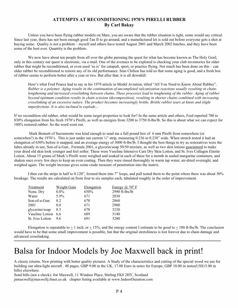
Mark Bennett of Sacramento was kind enough to send me a full pound box of 6 mm Pirelli from somewhere (orsomewhen?) in the 1970’s. This is just under out current ¼” strip, measuring 0.236 to 0.238” wide. When stretch tested it had anelongation of 650% before it snapped, and an average energy of 3000 ft-lbs/lb. I thought the best things to try as restoratives were thelubes already in use, Son-of-a-Gun , Formula 2001, a glycerin/soap 50/50 mixture, as well as two skin lotions guaranteed to makeyour dried old skin look younger and feel softer. These were Vaseline Intensive Care Dry Skin Lotion, and St. Ives Collagen ElastinLotion. About 15 grams of Mark’s Pirelli were weighed and soaked in each of these for a month in sealed margarine containers, andshaken once every few days to keep an even coating. Then they were rinsed thoroughly in warm tap water, air-dried overnight, andweighed again. The weight increase gives some crude measure of penetration into the matrix.
I then cut the strips in half to 0.120”, formed them into 7” loops, and pull tested them to the point where there was about 50%breakage. The results are calculated on from four to six samples each, tabulated roughly in the order of improvement.
Treatment Weight Gain Elongation Energy @ 70o FNone, Dry 0.0% 650% 2990 ft-lbs/lbWater 5.9% 671 2830Son-of-a-Gun 8.2 678 28602001 8.0 671 2900glycerine/soap 8.3 678 3230Vaseline Lotion 6.6 689 3140St. Ives Lotion 9.6 691 3280
Elongation is repeatable to + 1 inch, or + 15%, and the energy content I estimate to be good to + 100 ft-lbs/lb. The conclusionwould have to be that some small improvement is possible, but that the original stretchiness is lost forever due to chain damage andadvanced crosslinking.
Balsa for Indoor Models by Joe Maxwell back in print!A classic returns. New printing with better quality pictures. A Study of the characteristics and cutting of the special wood we use forbuilding our ultra-light aircraft . 48 pages. GBP 9.00 in the UK, 17.00 Euro in notes for Europe, GBP 10.00 in notes(US$15.00 inbills) elsewhere.Send bills (not a check): Joe Maxwell, 11 Windsor Place, Stirling FK8 2HY, [email protected] chapter listing available at www.IndoorDuration.com
P 5
Indoor Duration Flying Continues at Cardington.From Laurie Barr.
I am delighted to inform you that after surmounting many hurdles, we have the use once again of Hanger No 1. Although the roof issomewhat ‘perforated’, there is much more room to fly in and because we have ‘bought’ flying time, and are repairing some brokenwindows! We are sought after guests and not prisoners. However, the front end of the shed houses some small airships and there is aninvisible line across the floor that we MUST not cross. This would risk losing the chance to reinstate our presence in our ‘ancestralhome’.
The entry fee remains as £10.00 per person and this will also include spectators. This year, we will also charge £1.00 per contest entryto generate a bit more income. Access is by the A600 South of Bedford. Drive between the hangers and turn left. Along the rear endof the hanger are 2 doors, both of which will be locked after 10.45/11.00 a.m. The doors will open again at approximately 6.00p.m.This procedure is to ensure stable air and to stop anyone (including non B.M.F.A. people) not on the list from trespassing.
The following list shows all the dates as scheduled. This is subject to airship operational demands, in which case we shall give way ifthere is a conflict of interests. Best of all, is that the big main doors, WILL BE SHUT!!! and I expect the whole experience of flyinghere, will be relaxed and enjoyable.
Requirements for entry. All are mandatory.
You must be a current B.M.F.A. member, and you will be expected to show your card if requested.
There is so much space, that all kinds of scale and fun flyers are welcome, so long as you are on my list! (But no R/C or enginepowered flight)
No one, except our safety personnel, is allowed to climb any staircases, for any reason. Small children who cannot be controlled arenot recommended at this site.
This is a hard hat area, and although there are a few hats available, you are urged to buy your own ‘Bob The Builder’ type hat whichyou can get at builders yards, or B&Q etc, for under £5.
You must send a post card to Laurie Barr, giving all the dates you will attend, well before your arrival. Also state your full address, E-Mail address, B.M.F.A. number and phone number, in case we are given short notice to cancel any date. An s.a.e. would also be veryhelpful.
Schedule.
May 19th. F1L & No-CalMay 26th F1M & LPP Note: This new date replaces the meeting scheduled for the 1st/2nd of June. This is to June 16th F1D& Mini-stick avoid clashing with the reinstated outdoor Nationals.June 30th F1L & No-CalJuly 13th F1D first Euro trials.July 14th F1D second Euro trialsJuly 28th F1M & LPP also reserve date for Euro trialsAug. 11th F1L & No-CalAug 24th Practise/ LPP & No-Cal & Catapult Glider.Aug 25th F1L & F1M Indoor Nationals, over 2 daysAug 26th F1D & Mini-Stick. 2nd day Indoor NationalsSept 8th F1L & No-CalSept 22nd General reserve date.
This information is for all previous members, but we also want more BMFA members to attend, and we are advertising all dates, butthere is an upper limit to the numbers allowed at any meeting. We would also be very happy to welcome flyers from abroad.Send your dates ASAP to- Laurie Barr FSMAE, Herries Cottage, Winter Hill Road, Pinkneys Green,Maidenhead, Berks, SL6 6PJ. Tel 01628 487544. E-Mail. [email protected]
28. 04. 02.
P 6
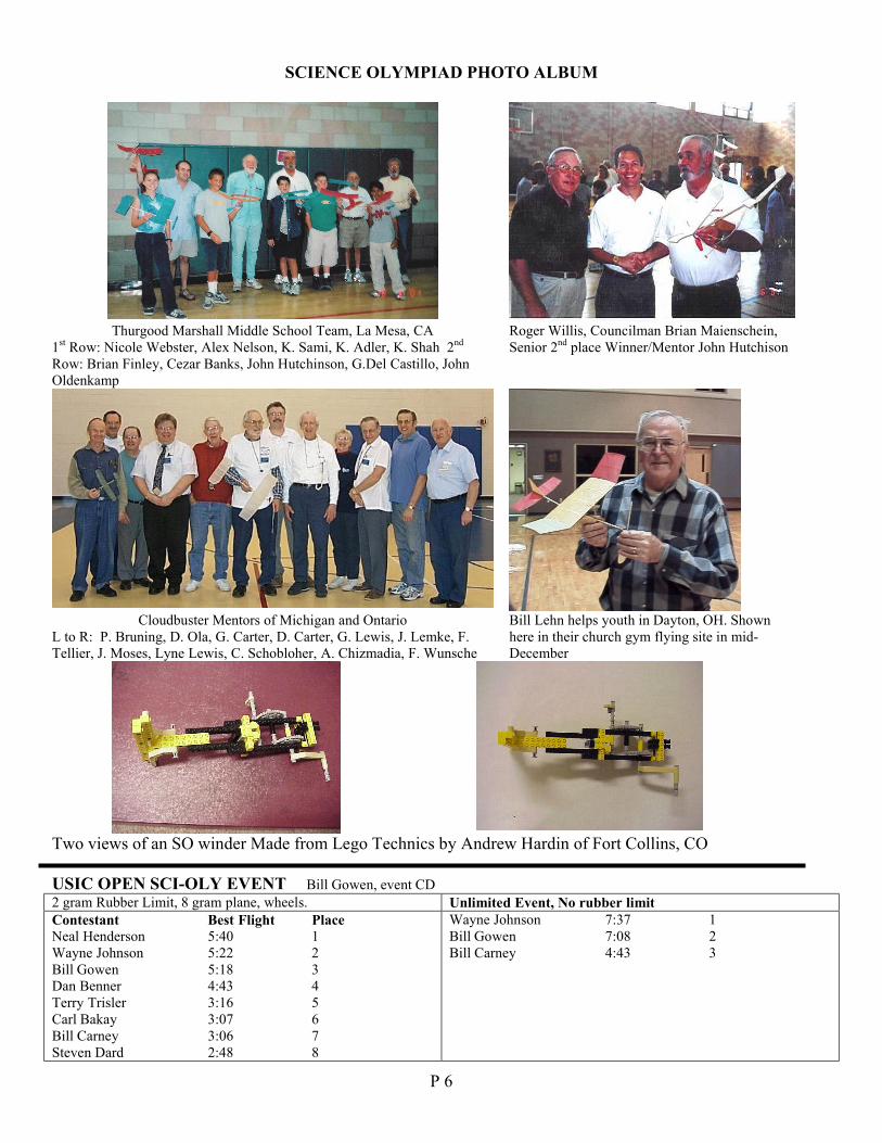
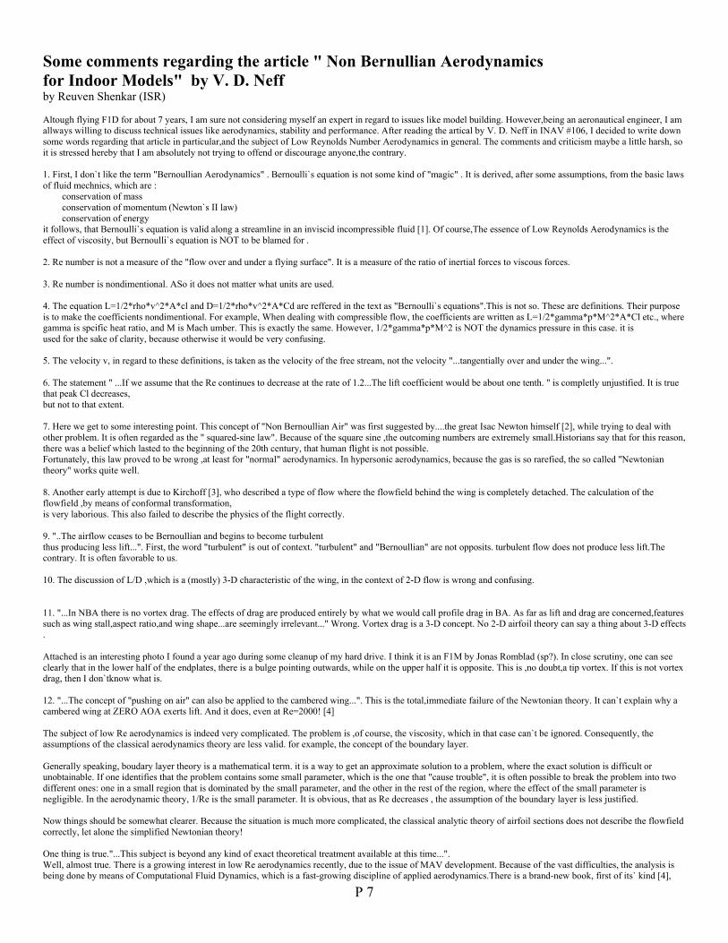
SCIENCE OLYMPIAD PHOTO ALBUM
Thurgood Marshall Middle School Team, La Mesa, CA1st Row: Nicole Webster, Alex Nelson, K. Sami, K. Adler, K. Shah 2nd
Row: Brian Finley, Cezar Banks, John Hutchinson, G.Del Castillo, JohnOldenkamp
Roger Willis, Councilman Brian Maienschein,Senior 2nd place Winner/Mentor John Hutchison
Cloudbuster Mentors of Michigan and OntarioL to R: P. Bruning, D. Ola, G. Carter, D. Carter, G. Lewis, J. Lemke, F.Tellier, J. Moses, Lyne Lewis, C. Schobloher, A. Chizmadia, F. Wunsche
Bill Lehn helps youth in Dayton, OH. Shownhere in their church gym flying site in mid-December
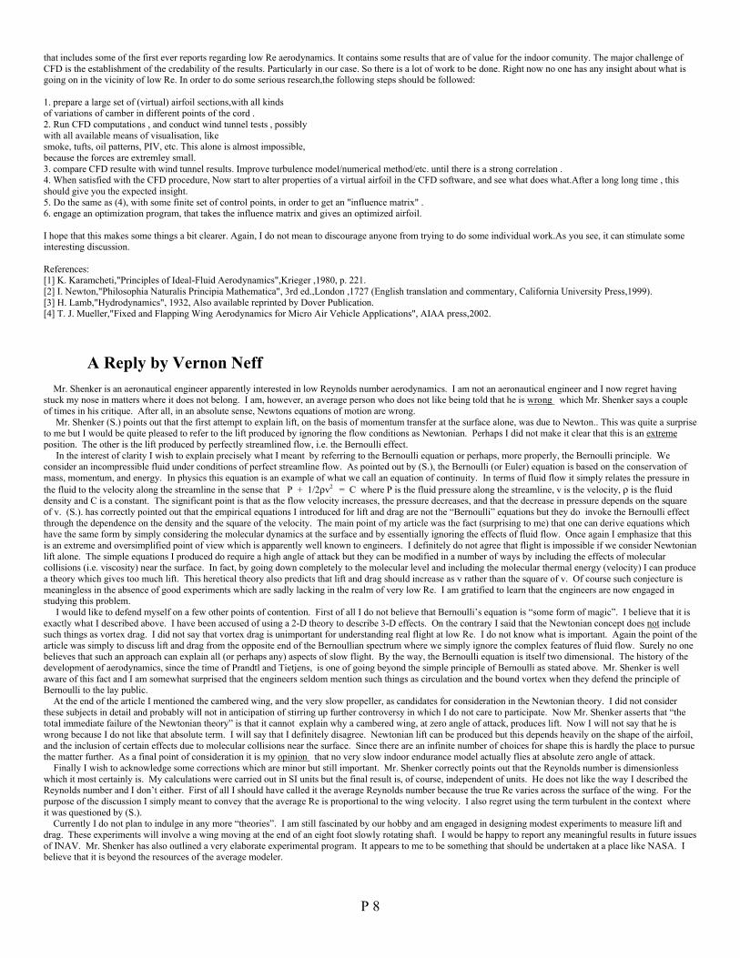
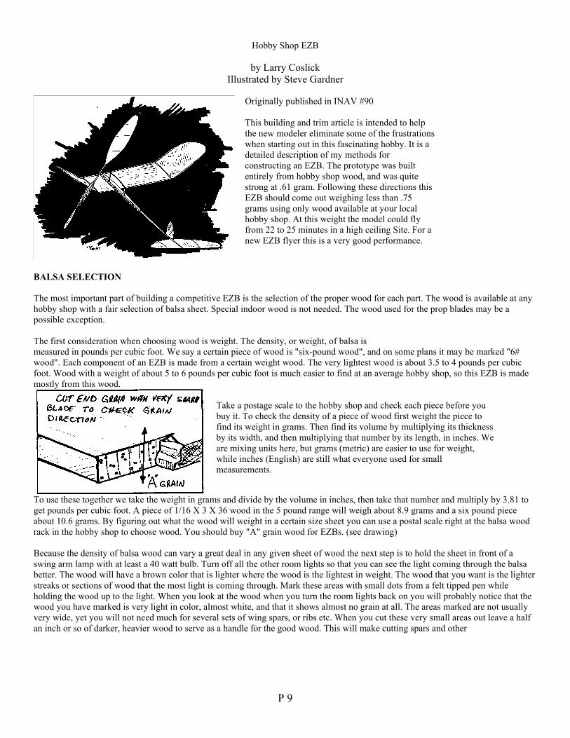
Two views of an SO winder Made from Lego Technics by Andrew Hardin of Fort Collins, CO
USIC OPEN SCI-OLY EVENT Bill Gowen, event CD2 gram Rubber Limit, 8 gram plane, wheels. Unlimited Event, No rubber limitContestant Best Flight PlaceNeal Henderson 5:40 1Wayne Johnson 5:22 2Bill Gowen 5:18 3Dan Benner 4:43 4Terry Trisler 3:16 5Carl Bakay 3:07 6Bill Carney 3:06 7Steven Dard 2:48 8
Wayne Johnson 7:37 1Bill Gowen 7:08 2Bill Carney 4:43 3
P 7
Some comments regarding the article " Non Bernullian Aerodynamicsfor Indoor Models" by V. D. Neffby Reuven Shenkar (ISR)
Altough flying F1D for about 7 years, I am sure not considering myself an expert in regard to issues like model building. However,being an aeronautical engineer, I amallways willing to discuss technical issues like aerodynamics, stability and performance. After reading the artical by V. D. Neff in INAV #106, I decided to write downsome words regarding that article in particular,and the subject of Low Reynolds Number Aerodynamics in general. The comments and criticism maybe a little harsh, soit is stressed hereby that I am absolutely not trying to offend or discourage anyone,the contrary.
1. First, I don`t like the term "Bernoullian Aerodynamics" . Bernoulli`s equation is not some kind of "magic" . It is derived, after some assumptions, from the basic lawsof fluid mechnics, which are :
conservation of massconservation of momentum (Newton`s II law)conservation of energy
it follows, that Bernoulli`s equation is valid along a streamline in an inviscid incompressible fluid [1]. Of course,The essence of Low Reynolds Aerodynamics is theeffect of viscosity, but Bernoulli`s equation is NOT to be blamed for .
2. Re number is not a measure of the "flow over and under a flying surface". It is a measure of the ratio of inertial forces to viscous forces.
3. Re number is nondimentional. ASo it does not matter what units are used.
4. The equation L=1/2*rho*v^2*A*cl and D=1/2*rho*v^2*A*Cd are reffered in the text as "Bernoulli`s equations".This is not so. These are definitions. Their purposeis to make the coefficients nondimentional. For example, When dealing with compressible flow, the coefficients are written as L=1/2*gamma*p*M^2*A*Cl etc., wheregamma is spcific heat ratio, and M is Mach umber. This is exactly the same. However, 1/2*gamma*p*M^2 is NOT the dynamics pressure in this case. it isused for the sake of clarity, because otherwise it would be very confusing.
5. The velocity v, in regard to these definitions, is taken as the velocity of the free stream, not the velocity "...tangentially over and under the wing...".
6. The statement " ...If we assume that the Re continues to decrease at the rate of 1.2...The lift coefficient would be about one tenth. " is completly unjustified. It is truethat peak Cl decreases,but not to that extent.
7. Here we get to some interesting point. This concept of "Non Bernoullian Air" was first suggested by....the great Isac Newton himself [2], while trying to deal withother problem. It is often regarded as the " squared-sine law". Because of the square sine ,the outcoming numbers are extremely small.Historians say that for this reason,there was a belief which lasted to the beginning of the 20th century, that human flight is not possible.Fortunately, this law proved to be wrong ,at least for "normal" aerodynamics. In hypersonic aerodynamics, because the gas is so rarefied, the so called "Newtoniantheory" works quite well.
8. Another early attempt is due to Kirchoff [3], who described a type of flow where the flowfield behind the wing is completely detached. The calculation of theflowfield ,by means of conformal transformation,is very laborious. This also failed to describe the physics of the flight correctly.
9. "..The airflow ceases to be Bernoullian and begins to become turbulentthus producing less lift...". First, the word "turbulent" is out of context. "turbulent" and "Bernoullian" are not opposits. turbulent flow does not produce less lift.Thecontrary. It is often favorable to us.
10. The discussion of L/D ,which is a (mostly) 3-D characteristic of the wing, in the context of 2-D flow is wrong and confusing.
11. "...In NBA there is no vortex drag. The effects of drag are produced entirely by what we would call profile drag in BA. As far as lift and drag are concerned,featuressuch as wing stall,aspect ratio,and wing shape...are seemingly irrelevant..." Wrong. Vortex drag is a 3-D concept. No 2-D airfoil theory can say a thing about 3-D effects.
Attached is an interesting photo I found a year ago during some cleanup of my hard drive. I think it is an F1M by Jonas Romblad (sp?). In close scrutiny, one can seeclearly that in the lower half of the endplates, there is a bulge pointing outwards, while on the upper half it is opposite. This is ,no doubt,a tip vortex. If this is not vortexdrag, then I don`tknow what is.
12. "...The concept of "pushing on air" can also be applied to the cambered wing...". This is the total,immediate failure of the Newtonian theory. It can`t explain why acambered wing at ZERO AOA exerts lift. And it does, even at Re=2000! [4]
The subject of low Re aerodynamics is indeed very complicated. The problem is ,of course, the viscosity, which in that case can`t be ignored. Consequently, theassumptions of the classical aerodynamics theory are less valid. for example, the concept of the boundary layer.
Generally speaking, boudary layer theory is a mathematical term. it is a way to get an approximate solution to a problem, where the exact solution is difficult orunobtainable. If one identifies that the problem contains some small parameter, which is the one that "cause trouble", it is often possible to break the problem into twodifferent ones: one in a small region that is dominated by the small parameter, and the other in the rest of the region, where the effect of the small parameter isnegligible. In the aerodynamic theory, 1/Re is the small parameter. It is obvious, that as Re decreases , the assumption of the boundary layer is less justified.
Now things should be somewhat clearer. Because the situation is much more complicated, the classical analytic theory of airfoil sections does not describe the flowfieldcorrectly, let alone the simplified Newtonian theory!
One thing is true."...This subject is beyond any kind of exact theoretical treatment available at this time...".Well, almost true. There is a growing interest in low Re aerodynamics recently, due to the issue of MAV development. Because of the vast difficulties, the analysis isbeing done by means of Computational Fluid Dynamics, which is a fast-growing discipline of applied aerodynamics.There is a brand-new book, first of its` kind [4],
P 8
that includes some of the first ever reports regarding low Re aerodynamics. It contains some results that are of value for the indoor comunity. The major challenge ofCFD is the establishment of the credability of the results. Particularly in our case. So there is a lot of work to be done. Right now no one has any insight about what isgoing on in the vicinity of low Re. In order to do some serious research,the following steps should be followed:
1. prepare a large set of (virtual) airfoil sections,with all kindsof variations of camber in different points of the cord .2. Run CFD computations , and conduct wind tunnel tests , possiblywith all available means of visualisation, likesmoke, tufts, oil patterns, PIV, etc. This alone is almost impossible,because the forces are extremley small.3. compare CFD resulte with wind tunnel results. Improve turbulence model/numerical method/etc. until there is a strong correlation .4. When satisfied with the CFD procedure, Now start to alter properties of a virtual airfoil in the CFD software, and see what does what.After a long long time , thisshould give you the expected insight.5. Do the same as (4), with some finite set of control points, in order to get an "influence matrix" .6. engage an optimization program, that takes the influence matrix and gives an optimized airfoil.
I hope that this makes some things a bit clearer. Again, I do not mean to discourage anyone from trying to do some individual work.As you see, it can stimulate someinteresting discussion.
References:[1] K. Karamcheti,"Principles of Ideal-Fluid Aerodynamics",Krieger ,1980, p. 221.[2] I. Newton,"Philosophia Naturalis Principia Mathematica", 3rd ed.,London ,1727 (English translation and commentary, California University Press,1999).[3] H. Lamb,"Hydrodynamics", 1932, Also available reprinted by Dover Publication.[4] T. J. Mueller,"Fixed and Flapping Wing Aerodynamics for Micro Air Vehicle Applications", AIAA press,2002.
A Reply by Vernon NeffMr. Shenker is an aeronautical engineer apparently interested in low Reynolds number aerodynamics. I am not an aeronautical engineer and I now regret having
stuck my nose in matters where it does not belong. I am, however, an average person who does not like being told that he is wrong which Mr. Shenker says a coupleof times in his critique. After all, in an absolute sense, Newtons equations of motion are wrong.
Mr. Shenker (S.) points out that the first attempt to explain lift, on the basis of momentum transfer at the surface alone, was due to Newton.. This was quite a surpriseto me but I would be quite pleased to refer to the lift produced by ignoring the flow conditions as Newtonian. Perhaps I did not make it clear that this is an extremeposition. The other is the lift produced by perfectly streamlined flow, i.e. the Bernoulli effect.
In the interest of clarity I wish to explain precisely what I meant by referring to the Bernoulli equation or perhaps, more properly, the Bernoulli principle. Weconsider an incompressible fluid under conditions of perfect streamline flow. As pointed out by (S.), the Bernoulli (or Euler) equation is based on the conservation ofmass, momentum, and energy. In physics this equation is an example of what we call an equation of continuity. In terms of fluid flow it simply relates the pressure inthe fluid to the velocity along the streamline in the sense that P + 1/2ρv2 = C where P is the fluid pressure along the streamline, v is the velocity, ρ is the fluiddensity and C is a constant. The significant point is that as the flow velocity increases, the pressure decreases, and that the decrease in pressure depends on the squareof v. (S.). has correctly pointed out that the empirical equations I introduced for lift and drag are not the “Bernoulli” equations but they do invoke the Bernoulli effect through the dependence on the density and the square of the velocity. The main point of my article was the fact (surprising to me) that one can derive equations whichhave the same form by simply considering the molecular dynamics at the surface and by essentially ignoring the effects of fluid flow. Once again I emphasize that thisis an extreme and oversimplified point of view which is apparently well known to engineers. I definitely do not agree that flight is impossible if we consider Newtonianlift alone. The simple equations I produced do require a high angle of attack but they can be modified in a number of ways by including the effects of molecularcollisions (i.e. viscosity) near the surface. In fact, by going down completely to the molecular level and including the molecular thermal energy (velocity) I can producea theory which gives too much lift. This heretical theory also predicts that lift and drag should increase as v rather than the square of v. Of course such conjecture ismeaningless in the absence of good experiments which are sadly lacking in the realm of very low Re. I am gratified to learn that the engineers are now engaged instudying this problem.
I would like to defend myself on a few other points of contention. First of all I do not believe that Bernoulli’s equation is “some form of magic”. I believe that it isexactly what I described above. I have been accused of using a 2-D theory to describe 3-D effects. On the contrary I said that the Newtonian concept does not includesuch things as vortex drag. I did not say that vortex drag is unimportant for understanding real flight at low Re. I do not know what is important. Again the point of thearticle was simply to discuss lift and drag from the opposite end of the Bernoullian spectrum where we simply ignore the complex features of fluid flow. Surely no onebelieves that such an approach can explain all (or perhaps any) aspects of slow flight. By the way, the Bernoulli equation is itself two dimensional. The history of thedevelopment of aerodynamics, since the time of Prandtl and Tietjens, is one of going beyond the simple principle of Bernoulli as stated above. Mr. Shenker is wellaware of this fact and I am somewhat surprised that the engineers seldom mention such things as circulation and the bound vortex when they defend the principle ofBernoulli to the lay public.
At the end of the article I mentioned the cambered wing, and the very slow propeller, as candidates for consideration in the Newtonian theory. I did not considerthese subjects in detail and probably will not in anticipation of stirring up further controversy in which I do not care to participate. Now Mr. Shenker asserts that “thetotal immediate failure of the Newtonian theory” is that it cannot explain why a cambered wing, at zero angle of attack, produces lift. Now I will not say that he iswrong because I do not like that absolute term. I will say that I definitely disagree. Newtonian lift can be produced but this depends heavily on the shape of the airfoil,and the inclusion of certain effects due to molecular collisions near the surface. Since there are an infinite number of choices for shape this is hardly the place to pursuethe matter further. As a final point of consideration it is my opinion that no very slow indoor endurance model actually flies at absolute zero angle of attack.
Finally I wish to acknowledge some corrections which are minor but still important. Mr. Shenker correctly points out that the Reynolds number is dimensionlesswhich it most certainly is. My calculations were carried out in SI units but the final result is, of course, independent of units. He does not like the way I described theReynolds number and I don’t either. First of all I should have called it the average Reynolds number because the true Re varies across the surface of the wing. For thepurpose of the discussion I simply meant to convey that the average Re is proportional to the wing velocity. I also regret using the term turbulent in the context whereit was questioned by (S.).
Currently I do not plan to indulge in any more “theories”. I am still fascinated by our hobby and am engaged in designing modest experiments to measure lift anddrag. These experiments will involve a wing moving at the end of an eight foot slowly rotating shaft. I would be happy to report any meaningful results in future issuesof INAV. Mr. Shenker has also outlined a very elaborate experimental program. It appears to me to be something that should be undertaken at a place like NASA. Ibelieve that it is beyond the resources of the average modeler.
P 9
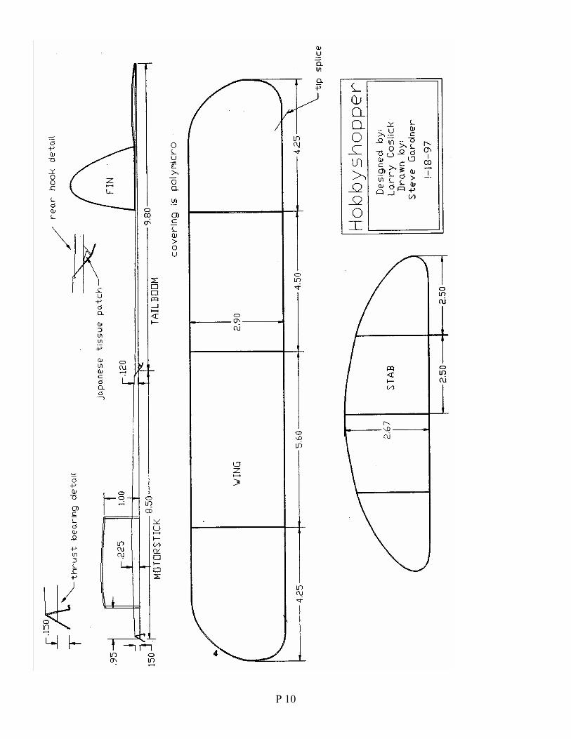
Hobby Shop EZB
by Larry CoslickIllustrated by Steve Gardner
Originally published in INAV #90
This building and trim article is intended to helpthe new modeler eliminate some of the frustrationswhen starting out in this fascinating hobby. It is adetailed description of my methods forconstructing an EZB. The prototype was builtentirely from hobby shop wood, and was quitestrong at .61 gram. Following these directions thisEZB should come out weighing less than .75grams using only wood available at your localhobby shop. At this weight the model could flyfrom 22 to 25 minutes in a high ceiling Site. For anew EZB flyer this is a very good performance.
BALSA SELECTION
The most important part of building a competitive EZB is the selection of the proper wood for each part. The wood is available at anyhobby shop with a fair selection of balsa sheet. Special indoor wood is not needed. The wood used for the prop blades may be apossible exception.
The first consideration when choosing wood is weight. The density, or weight, of balsa ismeasured in pounds per cubic foot. We say a certain piece of wood is "six-pound wood", and on some plans it may be marked "6#wood". Each component of an EZB is made from a certain weight wood. The very lightest wood is about 3.5 to 4 pounds per cubicfoot. Wood with a weight of about 5 to 6 pounds per cubic foot is much easier to find at an average hobby shop, so this EZB is mademostly from this wood.
Take a postage scale to the hobby shop and check each piece before youbuy it. To check the density of a piece of wood first weight the piece tofind its weight in grams. Then find its volume by multiplying its thicknessby its width, and then multiplying that number by its length, in inches. Weare mixing units here, but grams (metric) are easier to use for weight,while inches (English) are still what everyone used for smallmeasurements.
To use these together we take the weight in grams and divide by the volume in inches, then take that number and multiply by 3.81 toget pounds per cubic foot. A piece of 1/16 X 3 X 36 wood in the 5 pound range will weigh about 8.9 grams and a six pound pieceabout 10.6 grams. By figuring out what the wood will weight in a certain size sheet you can use a postal scale right at the balsa woodrack in the hobby shop to choose wood. You should buy "A" grain wood for EZBs. (see drawing)
Because the density of balsa wood can vary a great deal in any given sheet of wood the next step is to hold the sheet in front of aswing arm lamp with at least a 40 watt bulb. Turn off all the other room lights so that you can see the light coming through the balsabetter. The wood will have a brown color that is lighter where the wood is the lightest in weight. The wood that you want is the lighterstreaks or sections of wood that the most light is coming through. Mark these areas with small dots from a felt tipped pen whileholding the wood up to the light. When you look at the wood when you turn the room lights back on you will probably notice that thewood you have marked is very light in color, almost white, and that it shows almost no grain at all. The areas marked are not usuallyvery wide, yet you will not need much for several sets of wing spars, or ribs etc. When you cut these very small areas out leave a halfan inch or so of darker, heavier wood to serve as a handle for the good wood. This will make cutting spars and other
P 10
P 11
P 12
parts from this wood much easier. This method of picking out the wood will work even with 1/4 inch wood which you might use formotor stick wood. Cut the good wood out of the sheet and recalculate the density of the good piece. It might be as light and stiff as thespecial indoor wood and it has straight, smooth grain.
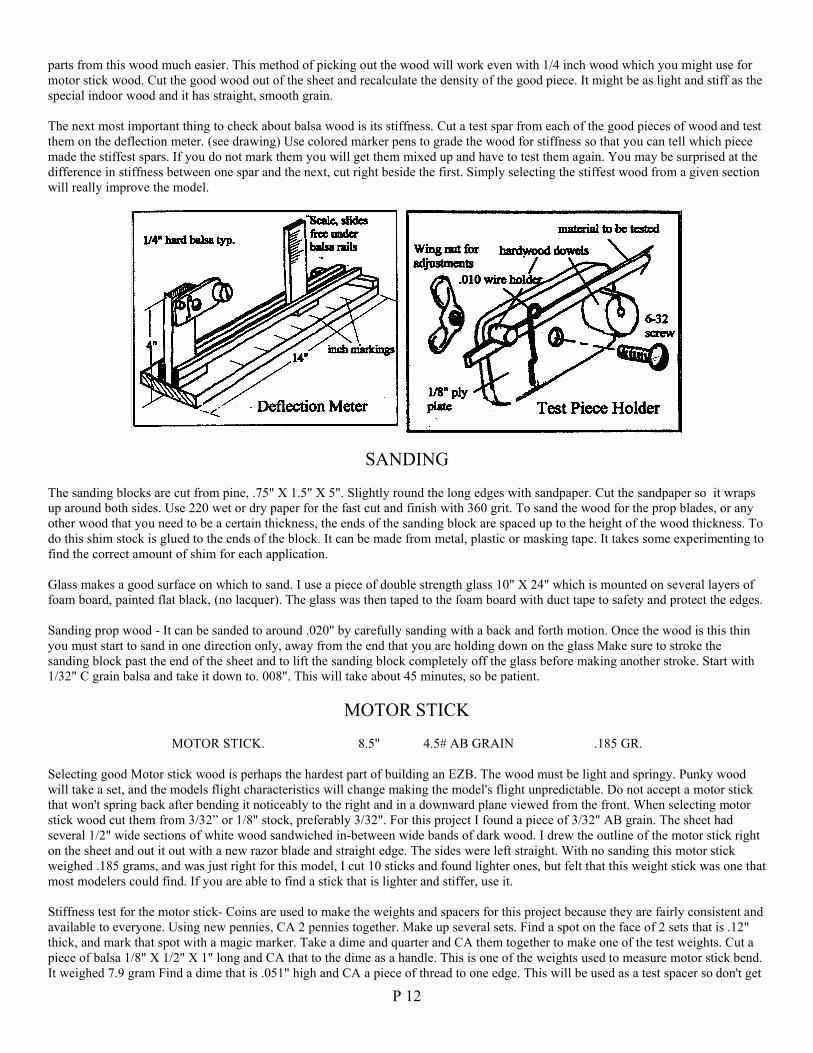
The next most important thing to check about balsa wood is its stiffness. Cut a test spar from each of the good pieces of wood and testthem on the deflection meter. (see drawing) Use colored marker pens to grade the wood for stiffness so that you can tell which piecemade the stiffest spars. If you do not mark them you will get them mixed up and have to test them again. You may be surprised at thedifference in stiffness between one spar and the next, cut right beside the first. Simply selecting the stiffest wood from a given sectionwill really improve the model.
SANDING
The sanding blocks are cut from pine, .75" X 1.5" X 5". Slightly round the long edges with sandpaper. Cut the sandpaper so it wrapsup around both sides. Use 220 wet or dry paper for the fast cut and finish with 360 grit. To sand the wood for the prop blades, or anyother wood that you need to be a certain thickness, the ends of the sanding block are spaced up to the height of the wood thickness. Todo this shim stock is glued to the ends of the block. It can be made from metal, plastic or masking tape. It takes some experimenting tofind the correct amount of shim for each application.
Glass makes a good surface on which to sand. I use a piece of double strength glass 10" X 24" which is mounted on several layers offoam board, painted flat black, (no lacquer). The glass was then taped to the foam board with duct tape to safety and protect the edges.
Sanding prop wood - It can be sanded to around .020" by carefully sanding with a back and forth motion. Once the wood is this thinyou must start to sand in one direction only, away from the end that you are holding down on the glass Make sure to stroke thesanding block past the end of the sheet and to lift the sanding block completely off the glass before making another stroke. Start with1/32" C grain balsa and take it down to. 008". This will take about 45 minutes, so be patient.
MOTOR STICK
MOTOR STICK. 8.5" 4.5# AB GRAIN .185 GR.
Selecting good Motor stick wood is perhaps the hardest part of building an EZB. The wood must be light and springy. Punky woodwill take a set, and the models flight characteristics will change making the model's flight unpredictable. Do not accept a motor stickthat won't spring back after bending it noticeably to the right and in a downward plane viewed from the front. When selecting motorstick wood cut them from 3/32” or 1/8" stock, preferably 3/32". For this project I found a piece of 3/32" AB grain. The sheet hadseveral 1/2" wide sections of white wood sandwiched in-between wide bands of dark wood. I drew the outline of the motor stick righton the sheet and out it out with a new razor blade and straight edge. The sides were left straight. With no sanding this motor stickweighed .185 grams, and was just right for this model, I cut 10 sticks and found lighter ones, but felt that this weight stick was one thatmost modelers could find. If you are able to find a stick that is lighter and stiffer, use it.
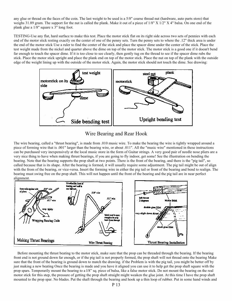
Stiffness test for the motor stick- Coins are used to make the weights and spacers for this project because they are fairly consistent andavailable to everyone. Using new pennies, CA 2 pennies together. Make up several sets. Find a spot on the face of 2 sets that is .12"thick, and mark that spot with a magic marker. Take a dime and quarter and CA them together to make one of the test weights. Cut apiece of balsa 1/8" X 1/2" X 1" long and CA that to the dime as a handle. This is one of the weights used to measure motor stick bend.It weighed 7.9 gram Find a dime that is .051" high and CA a piece of thread to one edge. This will be used as a test spacer so don't get
P 13
any glue or thread on the faces of the coin. The last weight to be used is a 5/8" coarse thread nut (hardware, auto parts store) thatweighs 31.89 gram. The support for the nut is called the plank. Make it out of a piece of 1/8" X 1/2" X 4" balsa. On one end of theplank glue a 1/8" square x 3" long foot.
TESTING-Use any flat, hard surface to make this test. Place the motor stick flat on its right side across two sets of pennies with eachend of the motor stick resting exactly on the center of one of the penny sets. Turn the penny sets to where the .12" thick area is underthe end of the motor stick Use a ruler to find the center of the stick and place the spacer dime under the center of the stick. Place thetest weight made from the nickel and quarter above the dime on top of the motor stick. The motor stick is a good one if it doesn't bendfar enough to touch the spacer dime. If it is too close to see clearly, then gently tug on the thread to see if the spacer dime rubs thestick. Place the motor stick upright and place the plank end on top of the motor stick. Place the nut on top of the plank with the outsideedge of the weight lining up with the outside of the motor stick. Again, the motor stick should not touch the dime. See drawing:
Wire Bearing and Rear Hook
The wire bearing, called a "thrust bearing", is made from .010 music wire. To make the bearing the wire is tightly wrapped around apiece of forming wire that is .001" larger than the bearing wire, or about .011". All the "music wire" mentioned in these instructionscan be purchased very inexpensively at the local music store in the form of Guitar strings. A very good pair of needle nose pliers are avery nice thing to have when making thrust bearings, if you are going to fly indoor, get some! See the illustration on bending thebearing. Note that the bearing supports the prop shaft at two points. There is the front of the bearing, and there is the "pig tail", socalled because that is its shape. After the bearing is formed, it will usually require some adjustment. The pig tail might be out of alignwith the from of the bearing, or vice-versa. Insert the forming wire in either the pig tail or front of the bearing and bend to realign. Thebearing must swing free on the prop shaft. This will not happen until the front of the bearing and the pig tail are in near perfectalignment.
Before mounting the thrust beating to the motor stick, make sure that the prop can be threaded through the bearing. If the bearingfront end is not ground down far enough, or if the pig tail is not properly formed, the prop shaft will not thread onto the bearing Makesure that the front of the bearing is ground down to match the drawing. if the Problem is with the pig tail, you might be better off byjust making a new beating Once the bearing is made and you have it aligned you can use it to help get the prop shaft square with theprop spars. Temporarily mount the bearing to a l/8” sq. piece of balsa, like a false motor stick. Do not mount the bearing on the realmotor stick for this step, the pressure of getting the prop shaft straight might weaken the glue joint. At this time I have the prop shaftmounted to the prop spar. No blades. Put the shaft through the bearing and hook up a thin loop of rubber. Put in some hand winds and
P 14
check to see if the spar is running true. If there is any wobble in the prop spars as they turn, make note of which spar is most forward,and then, grasping the prop spar where the wire shaft is bent and glued to the spar, bend the shaft until the prop spars turns straight. Goeasy and make very small corrections.
Remove the thrust bearing from its temporary mount and clean off any glue. Cut a 1/4" deep slot in the front of the motor stick. Anglethe slot to provide 2 degree left thrust. Place a piece of .010” wire 3" long through the bearing to check the thrust line. Slide thebearing into the slot. The reference wire should be .150" below the bottom of the motor stick. Do not place glue in the slot. The frontof the bearing should intersect the lower right angle of the motor stick. (see drawing) Take a new razor blade and cut the front of themotor stick to match the front angle of the bearing. Recheck for 1 degree down and 2 degree left thrust. The front of the bearing mustbe flush with the motor stick. Apply two thin coats of glue, to the wire and wood. Build up a small glue gusset where the pig tail andthe front of the bearing meets the wood. No extra glue is needed.
Cut a 1/64" slot at the rear of the motor stick. The motor stick and boom are joined by a scarf joint. Cut apiece of .009” wire 5/8"long and bend over one end 1/16" long. The 1/16" hook will be imbedded in the wood but the wire will be flush with the rear of themotor stick Tack glue the wire in place. Cut an angle on the tail boom to match the motor stick pre-glue both surfaces using Ambroidglue. Attach the boom and make sure the bottom of the boom is even with the bottom of the motor stick. Cut a gusset so that the endof the gusset is .125" below the motor stick The gusset is glued to the boom. Place a strip of Japanese tissue over the gusset and wire.You can angle the wire again where it breaks away from the gusset. Cut the wire to a usable length (see plans)
Boom
Boom 9.80" 6# .04 gram
I cannot stress enough the importance of a good EZB tail boom It needs to be fairly stiff and light. When they are not stiff enough themodel will usually flounder under high launch torque.
To get a tapered boom start with a sheet of good clear grained 6# wood 11" x 1" x .062” (1/16” sheet), and sand it down to a taperfrom .062” at one end to .028" at the other, using a 220 grit sanding block. Once the sheet is tapered in one direction the boom can becut to a taper in the other direction using a Harlan stripper or a good eye and a straight edge. This taper is from .075" to .028".
The boom is used on the model with the .075" side vertical so that the boom is stiffest in the vertical plane. If you build and use thedeflection meter the boom is tested in the same position. Insert the large end of the boom into the hold down and adjust the pivot andthe scale until the end of the boom is at the 0 mark With a .270 gram weight trimmed from a paper clip hung on the very end of theboom, there should be less than 1-1/8" deflection. A deflection of around 3/4" is a good boom.
Stab
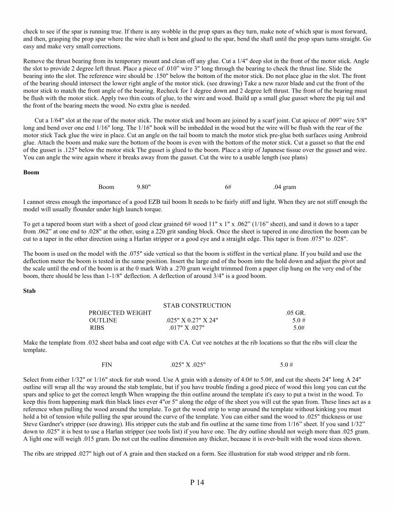
STAB CONSTRUCTIONPROJECTED WEIGHT .05 GR.OUTLINE .025" X 0.27" X 24" 5.0 #RIBS .017" X .027" 5.0#
Make the template from .032 sheet balsa and coat edge with CA. Cut vee notches at the rib locations so that the ribs will clear thetemplate.
FIN .025" X .025" 5.0 #
Select from either 1/32" or 1/16" stock for stab wood. Use A grain with a density of 4.0# to 5.0#, and cut the sheets 24" long A 24"outline will wrap all the way around the stab template, but if you have trouble finding a good piece of wood this long you can cut thespars and splice to get the correct length When wrapping the thin outline around the template it's easy to put a twist in the wood. Tokeep this from happening mark thin black lines ever 4"or 5" along the edge of the sheet you will cut the span from. These lines act as areference when pulling the wood around the template. To get the wood strip to wrap around the template without kinking you musthold a bit of tension while pulling the spar around the curve of the template. You can either sand the wood to .025" thickness or useSteve Gardner's stripper (see drawing). His stripper cuts the stab and fin outline at the same time from 1/16” sheet. If you sand 1/32”down to .025" it is best to use a Harlan stripper (see tools list) if you have one. The dry outline should not weigh more than .025 gram.A light one will weigh .015 gram. Do not cut the outline dimension any thicker, because it is over-built with the wood sizes shown.
The ribs are stripped .027" high out of A grain and then stacked on a form. See illustration for stab wood stripper and rib form.
P 15
WINGProjected Weight. .15 to .16 gr.LE .030" X .067" X 10.5" 5.5# .028 gr.LE .Deflection 5/16" with .340 gr., paper clip at 5"trailing edge. .027" X .067" X 16.5" 5.5# .031 gr.trailing edge Deflection I 1/16" with .20 gr. clip at 8"Tips .025" X .058" .025" X .035" 4# (2) .022 gr.Ribs .020 X .055 X 3" 4.5# (3) .010 gr.Posts------.035 X .062 X 1.25" 6# (2) .009 gr.Paper tubes--3 wraps of Condenser Paper, or light Japanese tissue (2) .003 gr.
The leading and training edge spars are cut from selected sheets of A grain stock as described in the wood selection article. Use a JimJones or Harlan stripper to cut the spars to shape. Test each spar for weight and stiffness using the deflection gauge. Select the L/E andtrailing edge spar that comes closest to the spec sheet. The front spar is the most important component of the wing. It must be stifferthen the rear spar for the wing to resist unwanted flexing. To save weight the wing tips can be cut from very light wood. If you canfind 3.5# use it.
Leading edge spar - This spar is 10.5" long and is not tapered except for the last 3/4" on each end. Hand sand or cut this taper from.067" to .058".
Trailing edge spar - This spar is 16.5" long and the last 4" of the top of each end tapers from .067" to .035". Scribe a line to show thetaper and sand or cut along the line. Mark the top of this spar with a felt marker to prevent turning the spar up side down.
Tips - The tip wood needs to be sanded from 1/32" stock to around .025", not less than .022". Use 4# wood or less. Use a Harlanstripper, if you have one, or a straight edge to taper the 8" tips from .058" to .035".
Template - Mat board of the kind used to mount pictures or photos makes very good template material. It is available at all art storesand most picture framers. Balsa sheet 1/16” thick is also good. Make sure that allow for the width of the spars and another .050" whenyou make the template to stay under the 3" chord limit for EZBs. Apply CA glue around the entire template edge and sand smoothwhen dry. This will prevent the template from swelling when you use water to make the bend in the tips. Pin the template to yourbuilding board with poster pins. These are 3/8" long pins with plastic heads. Push the pin all the way down to the heads so that theyare not in the way of construction.
Construction - The first step is to soak the tip wood in water to allow them to be bent around the template. Gene Joshu suggested agood way to soak the tip and stab outlines. Lay the wood on a Formica counter, top or table and use a watercolor paintbrush to run abead of water along both sides of the wood. Let the water soak for about a minute, then place the tip with the .035" end at the rearsplice marked on the plans. Trap this end of the tip in place with a balsa block and a pin and wrap the wood around the template whileholding a very light tension. The other end of the tip will extend past the front splice. This will be trimmed off later when it will bematched to the leading edge spar. Once the tips are dry (about an hour) lay the rear spar in place with the top side marking up, and cutthe scarf joints in the spar and the tip. Pre-glue and attach each tip to the rear spar. Place the leading edge on the template. The woodwill extend beyond the rib. Make a scarf joint 1/8" beyond the rib and attach both tips to the leading edge spar. Be careful whenmaking the last joint, its easy to cut either the tip or the spar too short.
P 16
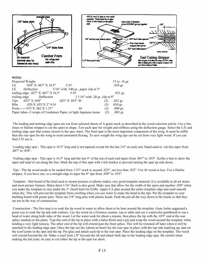
Ribs - Sand a small sheet of 4.5# A grain balsa to .020". Strip 5 straight ribs .020" X .055" X 3.25", two of these are spares. Soak theribs and then stack them on the rib form to dry. (See illustration) The ribs are placed with the front end against the leading edge spar,then they are carefully trimmed to length at the trailing edge spar. Check to be certain that the rib is not too long, forcing the spar apartor adding bend to the rib. Pre-glue the ends of the rib and the spot on the spars where the rib will be glued. Wait about ten seconds andplace glue on one end of the rib and attach it to the spar in the proper place, then glue the other end of the rib to the spar. Make surethat the rib is vertical before this glue dries. After the ribs are placed its best to leave the wing on the template for one day. Make surethat the center rib is installed perpendicular to the wing spars to properly locate the wing posts. The wing post jig centers each post onthe rib location. This jig is illustrated in the final assembly section.
Covering - This subject is not covered in this issue. I did a covering article which appeared in INAV issue 65,66,67 Jan93. If you needa copy, send a self addressed stamped envelope to INAV.
Placing Dihedral - After the wing is covered turn the wing over on a clean flat surface. Take a sharp double edged blade and cut scarfjoints on the tip side next to each rib. Don't cut all the way through the spars. Lift the center section of the wing 2" above the table andbreak each joint where the cut was made. The tips will touch the table. Now support the center section with balsa blocks. Place a smallamount of thinned carpenters glue in each joint. After 2 minutes re-glue the joint. Carefully turn the wing over and block up each tip1.7". Make sure the wing is not over 18" long from tip to tip. Place a small weight on top of the spar at each tip rib. After about onehour lift the wing and inspect each dihedral break. If there is a gap, close it with a sliver of balsa.
Wing Posts - Strip the posts 1/32" X 1/16" X 1" , 6# wood. Wing post installation is described in the final assembly section.
Paper tubes - Cut another piece of 1/32" X 1/16" balsa to use as a form for the tubes. Cut the tissue or condenser paper .into 3/8"X1"pieces. Apply a bit of ambroid glue to one end of the form and place the tissue so that it is ready to wrap. The tissue should extend offthe end of the form by about a 1/16" so that you will have an end to grab when you pull the tube off of the form. The glue will helpyou start the wrapping by holding the end of the tissue. After the first turn, when the tissue is starting its second layer, put a fairlylarge blob of glue on the tissue right at the form Now as you continue to wrap the tissue around the form this glue will spread out andcoat each wrap in the whole length of the tube. Once you have three or four turns wrapped around the form immediately grasp the endof the tube extruding past the end of the form with your finger and pull the tube off the form. Set aside to dry an hour, then place backon the form and recoat the outside of the tube. Once the glue is on the tube pull the tube off again and let dry completely. Do not putthe tubes on the wing posts too soon, or they will stick. A good idea from Steve Gardner.Prop
Projected Weight .170 gr.Prop Spar-------12.5" X .047" X .075"---.025" X .025"---5.5# .035 gr.Prop Spar-------B grain-----Deflection 3/8" each side with a .20 gr. paper clipProp Spar Wire---.010 music wire + spar .044 gr.Prop Blades---------5.0 sq. in each blade-----------4.0# .008" (2) ---------.120 gr.Prop 14" X 25" Pitch
Prop Spar - The spar is double tapered from 1/16” B grain, 5.5#. Look for clear uniform grain and cut several 1" X 7". Sand a taperfrom 050" to .025" using a 220 grit sanding block. The spars are double tapered by cutting the second taper into them when they arecut from the sheet. Use a Harlan stripper or a straight edge to make this cut. Make several spar sets from each sheet. Test each spar fordeflection as you did the boom. Both prop spare should match each other closely in deflection. Record the deflection of each set ofspars. Pick the lightest stiffest set of spars to use for the prop. When your final selection is made, cut a long scarf joint on the big endof each spar. (see drawing) Pre-glue the ends of the spars and join the two with ambroid. Pick up the spar after several minutes ofdrying time and realign if necessary.
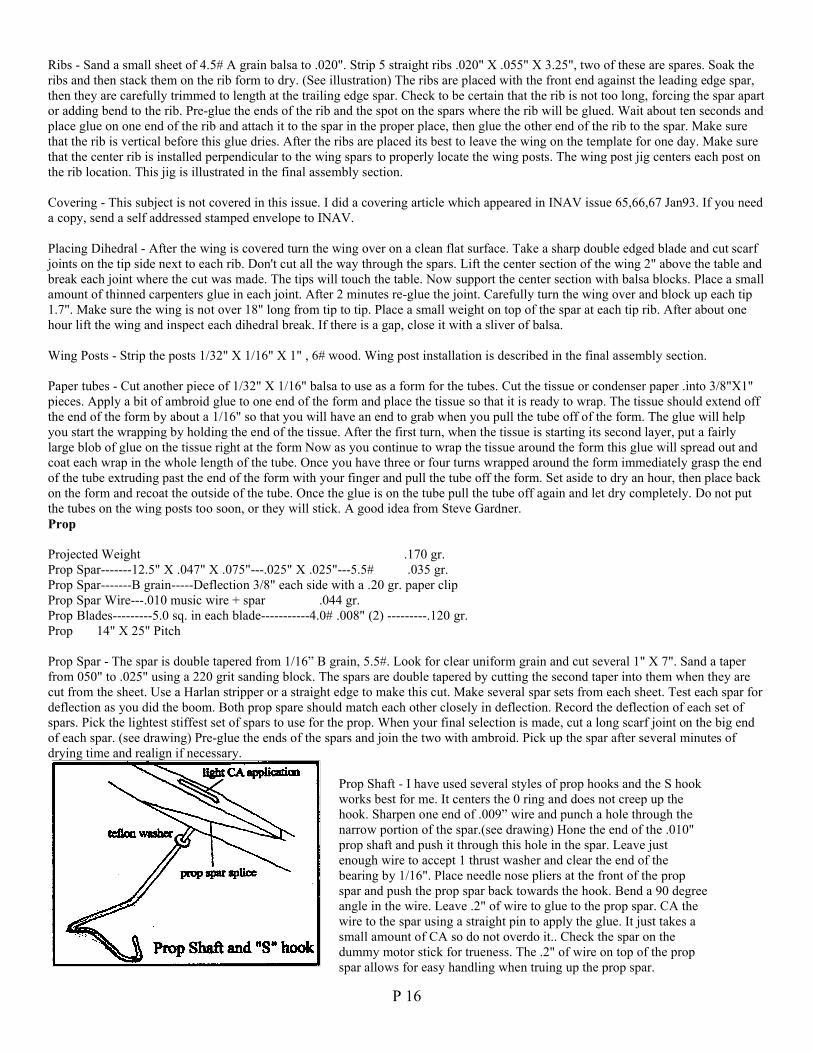
Prop Shaft - I have used several styles of prop hooks and the S hookworks best for me. It centers the 0 ring and does not creep up thehook. Sharpen one end of .009” wire and punch a hole through thenarrow portion of the spar.(see drawing) Hone the end of the .010"prop shaft and push it through this hole in the spar. Leave justenough wire to accept 1 thrust washer and clear the end of thebearing by 1/16". Place needle nose pliers at the front of the propspar and push the prop spar back towards the hook. Bend a 90 degreeangle in the wire. Leave .2" of wire to glue to the prop spar. CA thewire to the spar using a straight pin to apply the glue. It just takes asmall amount of CA so do not overdo it.. Check the spar on thedummy motor stick for trueness. The .2" of wire on top of the propspar allows for easy handling when truing up the prop spar.
P 17
Blades - If at all possible, order .008” C grain from Indoor Model Supply. It's difficult to find good C grain at a hobby shop. If youwant to use hobby shop wood for the prop you must choose the lightest piece of C grain 1/32" balsa that you can find. You can't use5# wood and expect the prop to weigh .17 grams. The EZB will fly OK with a heavier prop, but the performance will fall off quicklywith every bit of extra weight.
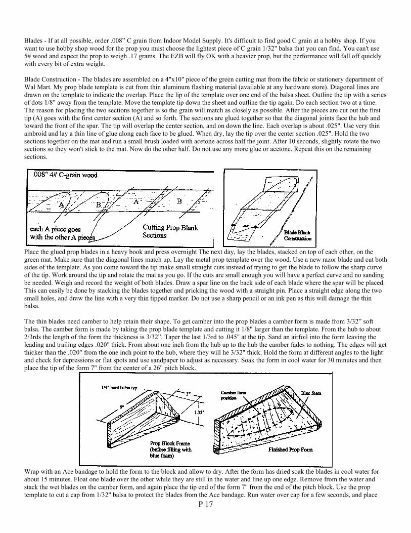
Blade Construction - The blades are assembled on a 4"x10" piece of the green cutting mat from the fabric or stationery department ofWal Mart. My prop blade template is cut from thin aluminum flashing material (available at any hardware store). Diagonal lines aredrawn on the template to indicate the overlap. Place the lip of the template over one end of the balsa sheet. Outline the tip with a seriesof dots 1/8" away from the template. Move the template tip down the sheet and outline the tip again. Do each section two at a time.The reason for placing the two sections together is so the grain will match as closely as possible. After the pieces are cut out the firsttip (A) goes with the first center section (A) and so forth. The sections are glued together so that the diagonal joints face the hub andtoward the front of the spar. The tip will overlap the center section, and on down the line. Each overlap is about .025". Use very thinambroid and lay a thin line of glue along each face to be glued. When dry, lay the tip over the center section .025". Hold the twosections together on the mat and run a small brush loaded with acetone across half the joint. After 10 seconds, slightly rotate the twosections so they won't stick to the mat. Now do the other half. Do not use any more glue or acetone. Repeat this on the remainingsections.
Place the glued prop blades in a heavy book and press overnight The next day, lay the blades, stacked on top of each other, on thegreen mat. Make sure that the diagonal lines match up. Lay the metal prop template over the wood. Use a new razor blade and cut bothsides of the template. As you come toward the tip make small straight cuts instead of trying to get the blade to follow the sharp curveof the tip. Work around the tip and rotate the mat as you go. If the cuts are small enough you will have a perfect curve and no sandingbe needed. Weigh and record the weight of both blades. Draw a spar line on the back side of each blade where the spar will be placed.This can easily be done by stacking the blades together and pricking the wood with a straight pin. Place a straight edge along the twosmall holes, and draw the line with a very thin tipped marker. Do not use a sharp pencil or an ink pen as this will damage the thinbalsa.
The thin blades need camber to help retain their shape. To get camber into the prop blades a camber form is made from 3/32” softbalsa. The camber form is made by taking the prop blade template and cutting it 1/8" larger than the template. From the hub to about2/3rds the length of the form the thickness is 3/32”. Taper the last 1/3rd to .045" at the tip. Sand an airfoil into the form leaving theleading and trailing edges .020" thick. From about one inch from the hub up to the hub the camber fades to nothing. The edges will getthicker than the .020" from the one inch point to the hub, where they will he 3/32" thick. Hold the form at different angles to the lightand check for depressions or flat spots and use sandpaper to adjust as necessary. Soak the form in cool water for 30 minutes and thenplace the tip of the form 7" from the center of a 26" pitch block.
Wrap with an Ace bandage to hold the form to the block and allow to dry. After the form has dried soak the blades in cool water forabout 15 minutes. Float one blade over the other while they are still in the water and line up one edge. Remove from the water andstack the wet blades on the camber form, and again place the tip end of the form 7" from the end of the pitch block. Use the proptemplate to cut a cap from 1/32" balsa to protect the blades from the Ace bandage. Run water over cap for a few seconds, and place
P 18
over the blades on the camber form. Wrap the pitch block, form, blades, and cap with the Ace bandage. Let the blades air dry for twodays. To separate the blades once they are dry, place a single edge razor blade between the two blades and run the blunt edge of therazor blade carefully around perimeter of the prop blades.
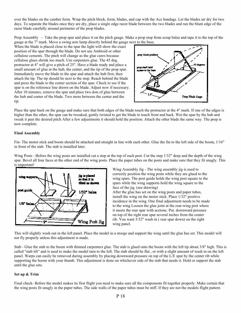
Prop Assembly - Take the prop spar and place it on the pitch gauge. Make a prop stop from scrap balsa and tape it to the top of thegauge at the 7" mark. Move a swing arm lamp directly behind the gauge next to the base.When the blade is placed close to the spar the light will show the exactposition of the spar through the blade. Do not use Ambroid or othercellulose cements. The pitch will change as the glue cures becausecellulose glues shrink too much. Use carpenters glue. The 45 deg.protractor at 4" will give a pitch of 25". Have a blade ready and place asmall amount of glue at the hub, the center, and the tip of the prop spar.Immediately move the blade to the spar and attach the hub first, thenattach the tip. The tip should be next to the stop. Reach behind the bladeand press the blade to the center section of the spar. Check to see if thespar is on the reference line drawn on the blade. Adjust now if necessary.After 10 minutes, remove the spar and place two dots of glue betweenthe hub and center of the blade. Two more between the center and thetip.
Place the spar back on the gauge and make sure that both edges of the blade touch the protractor at the 4" mark. If one of the edges ishigher than the other, the spar can be tweaked, gently twisted to get the blade to touch front and back. Wet the spar by the hub andtweak it past the desired pitch After a few adjustments it should hold the position. Attach the other blade the same way. The prop isnow complete.
Final Assembly
Fin- The motor stick and boom should be attached and straight in line with each other. Glue the fin to the left side of the boom, 1/16"in front of the stab. The stab is installed later.
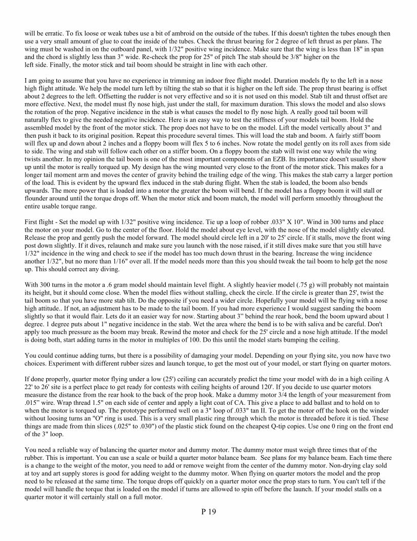
Wing Posts - Before the wing posts are installed cut a step at the top of each post. Cut the step 1/32" deep and the depth of the wingspar. Bevel all four faces at the other end of the wing posts. Place the paper tubes on the posts and make sure that they fit snugly. Thisis important!
Wing Assembly Jig - The wing assembly jig is used tocorrectly position the wing posts while they are glued to thewing spars. The post guide holds the wing post square to thespars while the wing supports hold the wing square to theface of the jig. (see drawing)After the glue has set on the wing posts and paper tubes,install the wing on the motor stick. Place 1/32" positiveincidence in the wing. One final adjustment needs to be madeto the wing Loosen the glue joint at the rear-wing post whereit meets the rear spar with acetone. Put. downward pressureon top of the right rear spar several inches from the centerrib. You want 3/32" wash in ( rear spar down) on the rightwing panel.
This will slightly wash out in the left panel. Place the model in a stooge and support the wing until the glue has set. This model willnot fly properly unless this adjustment is made.
Stab - Glue the stab to the boom with thinned carpenters glue. The stab is glued onto the boom with the left tip about 3/8" high. This iscalled "stab tilt” and is used to make the model turn to the left. The stab should be flat , or with a slight amount of wash in on the leftpanel. Warps can easily be removed during assembly by placing downward pressure on top of the L/E spar by the center rib whilesupporting the boom with your thumb. This adjustment is done on whichever side of the stab that needs it. Hold or support the stabuntil the glue sets.
Set up & Trim
Final check- Before the model makes its first flight you need to make sure all the components fit together properly. Make certain thatthe wing posts fit snugly in the paper tubes. The side walls of the paper tubes must be stiff. If they are not the models flight pattern
P 19
will be erratic. To fix loose or weak tubes use a bit of ambroid on the outside of the tubes. If this doesn't tighten the tubes enough thenuse a very small amount of glue to coat the inside of the tubes. Check the thrust bearing for 2 degree of left thrust as per plans. Thewing must be washed in on the outboard panel, with 1/32" positive wing incidence. Make sure that the wing is less than 18" in spanand the chord is slightly less than 3" wide. Re-check the prop for 25" of pitch The stab should be 3/8" higher on theleft side. Finally, the motor stick and tail boom should be straight in line with each other.
I am going to assume that you have no experience in trimming an indoor free flight model. Duration models fly to the left in a nosehigh flight attitude. We help the model turn left by tilting the stab so that it is higher on the left side. The prop thrust bearing is offsetabout 2 degrees to the left. Offsetting the rudder is not very effective and so it is not used on this model. Stab tilt and thrust offset aremore effective. Next, the model must fly nose high, just under the stall, for maximum duration. This slows the model and also slowsthe rotation of the prop. Negative incidence in the stab is what causes the model to fly nose high. A really good tail boom willnaturally flex to give the needed negative incidence. Here is an easy way to test the stiffness of your models tail boom. Hold theassembled model by the front of the motor stick. The prop does not have to be on the model. Lift the model vertically about 3" andthen push it back to its original position. Repeat this procedure several times. This will load the stab and boom. A fairly stiff boomwill flex up and down about 2 inches and a floppy boom will flex 5 to 6 inches. Now rotate the model gently on its roll axes from sideto side. The wing and stab will follow each other on a stiffer boom. On a floppy boom the stab will twist one way while the wingtwists another. In my opinion the tail boom is one of the most important components of an EZB. Its importance doesn't usually showup until the motor is really torqued up. My design has the wing mounted very close to the front of the motor stick. This makes for alonger tail moment arm and moves the center of gravity behind the trailing edge of the wing. This makes the stab carry a larger portionof the load. This is evident by the upward flex induced in the stab during flight. When the stab is loaded, the boom also bendsupwards. The more power that is loaded into a motor the greater the boom will bend. If the model has a floppy boom it will stall orflounder around until the torque drops off. When the motor stick and boom match, the model will perform smoothly throughout theentire usable torque range.
First flight - Set the model up with 1/32" positive wing incidence. Tie up a loop of robber .033" X 10". Wind in 300 turns and placethe motor on your model. Go to the center of the floor. Hold the model about eye level, with the nose of the model slightly elevated.Release the prop and gently push the model forward. The model should circle left in a 20' to 25' circle. If it stalls, move the front wingpost down slightly. If it dives, relaunch and make sure you launch with the nose raised, if it still dives make sure that you still have1/32" incidence in the wing and check to see if the model has too much down thrust in the bearing. Increase the wing incidenceanother 1/32", but no more than 1/16" over all. If the model needs more than this you should tweak the tail boom to help get the noseup. This should correct any diving.
With 300 turns in the motor a .6 gram model should maintain level flight. A slightly heavier model (.75 g) will probably not maintainits height, but it should come close. When the model flies without stalling, check the circle. If the circle is greater than 25', twist thetail boom so that you have more stab tilt. Do the opposite if you need a wider circle. Hopefully your model will be flying with a nosehigh attitude.. If not, an adjustment has to be made to the tail boom. If you had more experience I would suggest sanding the boomslightly so that it would flair. Lets do it an easier way for now. Starting about 3” behind the rear hook, bend the boom upward about 1degree. 1 degree puts about 1" negative incidence in the stab. Wet the area where the bend is to be with saliva and be careful. Don'tapply too much pressure as the boom may break. Rewind the motor and check for the 25' circle and a nose high attitude. If the modelis doing both, start adding turns in the motor in multiples of 100. Do this until the model starts bumping the ceiling.
You could continue adding turns, but there is a possibility of damaging your model. Depending on your flying site, you now have twochoices. Experiment with different rubber sizes and launch torque, to get the most out of your model, or start flying on quarter motors.
If done properly, quarter motor flying under a low (25') ceiling can accurately predict the time your model with do in a high ceiling A22' to 26' site is a perfect place to get ready for contests with ceiling heights of around 120'. If you decide to use quarter motorsmeasure the distance from the rear hook to the back of the prop hook. Make a dummy motor 3/4 the length of your measurement from.015” wire. Wrap thread 1.5" on each side of center and apply a light coat of CA. This give a place to add ballast and to hold on towhen the motor is torqued up. The prototype performed well on a 3" loop of .033" tan II. To get the motor off the hook on the winderwithout loosing turns an "O" ring is used. This is a very small plastic ring through which the motor is threaded before it is tied. Thesethings are made from thin slices (.025" to .030") of the plastic stick found on the cheapest Q-tip copies. Use one 0 ring on the front endof the 3" loop.
You need a reliable way of balancing the quarter motor and dummy motor. The dummy motor must weigh three times that of therubber. This is important. You can use a scale or build a quarter motor balance beam. See plans for my balance beam. Each time thereis a change to the weight of the motor, you need to add or remove weight from the center of the dummy motor. Non-drying clay soldat toy and art supply stores is good for adding weight to the dummy motor. When flying on quarter motors the model and the propneed to be released at the same time. The torque drops off quickly on a quarter motor once the prop stars to turn. You can't tell if themodel will handle the torque that is loaded on the model if turns are allowed to spin off before the launch. If your model stalls on aquarter motor it will certainly stall on a full motor.
P 20
I'll give you an idea of what the prototype looked like when loaded with .13 inches oz. of torque.. Hold the wound model in front ofyou, and sight down the motor stick to get the proper view. The wing was fiat with no warps in either wing panel. The motor stick andboom were bent downward in a slight arc. The stab had lost some of its tilt but was still high on the left side. This torque was morethan enough to get to the 116 foot ceiling at Johnson City.
One last bit of information on motor sticks. If your model stalls at a high launch torque and you think the boom is OK the problemcould be with the motor stick. It might be too strong. The model will fly great on low to moderate torque, but stalls when released atthe desired launch torque. Try this. If the model stalls at .12 inches oz, wind to .15 inch oz. and relaunch. If it climbs 4 to 5 feet higherthen stalls, the motor stick is probably too stiff. To make certain wind and launch at .18. If the model climbs to around 20 feet beforestalling the motor stick is definitely too strong. Take a sanding block and sand the bottom of the motorstick from the rear post tube toone inch in front of the rear hook. Be careful and only make a few strokes with the paper and make another flight. Its extremely easyto remove too much wood and ruin the motor stick. Relaunch at .12 in oz of torque to check if you have removed enough wood. Whenthe stalling at this torque goes away stop sanding the motor stick.
Good Luck !! Larry Coslick
West Baden Fun Fly Exhibition
Fly in perhaps the best Cat III (30 meters) in the world.West Baden Springs motel in West Baden, Indiana is the place.
August 3 & 4 2002 is the date.
Tentative Schedule for the Contest
Friday Aug 2nd Setup Noon – 4 pm. A.C. may be on.Saturday Aug 3rd Setup and Fly 8 am – 4 pm A.C. off
Scale Exhibition 11am – 4 pmSunday Aug 4th Fly 8 am – 5 pm A.C. off
The disk will be shrouded in plastic. J, S, O will be flown as separate classes. No entry fee. No judgedevents. No prizes. Just the joy of flying free in the historic West Baden Atrium.
Entry & Housing information – Andrea Hill (Historic Indiana) (No entry fee) (800)-450-4534
Contacts: Dave R. Thomson, CD, 5432 Haft Rd., Cincinnati, OH 45247, (513)-574-8322Walt van Gorder, Ast. CD 5669 Victoryview Lane, Cincinnati, OH 45233, (513)-922-3351
--------------------------------------------------------------------------------------------------------------------------------Must register to fly. Copy this page, fill out, and return to Dave or Walt by July 7, 2002. Thanks!!
Events 201, 202, 203, 204, 205, 206, 207, 208, 209, 210211, 212, 214, 216, 217, 218, 219, 220, 221.
Please circle events you’ll fly. No judged events.
I may / will (circle one) attend. -----------------------------------------------------------------Sign
-----------------------------------------------------------------Print Name
P 21
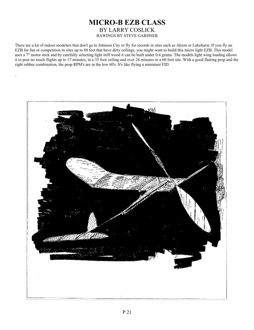
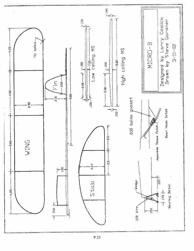
MICRO-B EZB CLASSBY LARRY COSLICK
RAWINGS BY STEVE GARDNER
There are a lot of indoor modelers that don't go to Johnson City or fly for records in sites such as Akron or Lakehurst. If you fly anEZB for fun or competition in sites up to 60 feet that have dirty ceilings, you might want to build this micro light EZB. This modeluses a 7" motor stick and by carefully selecting light stiff wood it can be built under 0.4 grams. The models light wing loading allowsit to post no touch flights up to 17 minutes, in a 35 foot ceiling and over 24 minutes in a 60 foot site. With a good flairing prop and theright rubber combination, the prop RPM's are in the low 60's. It's like flying a miniature FID
.
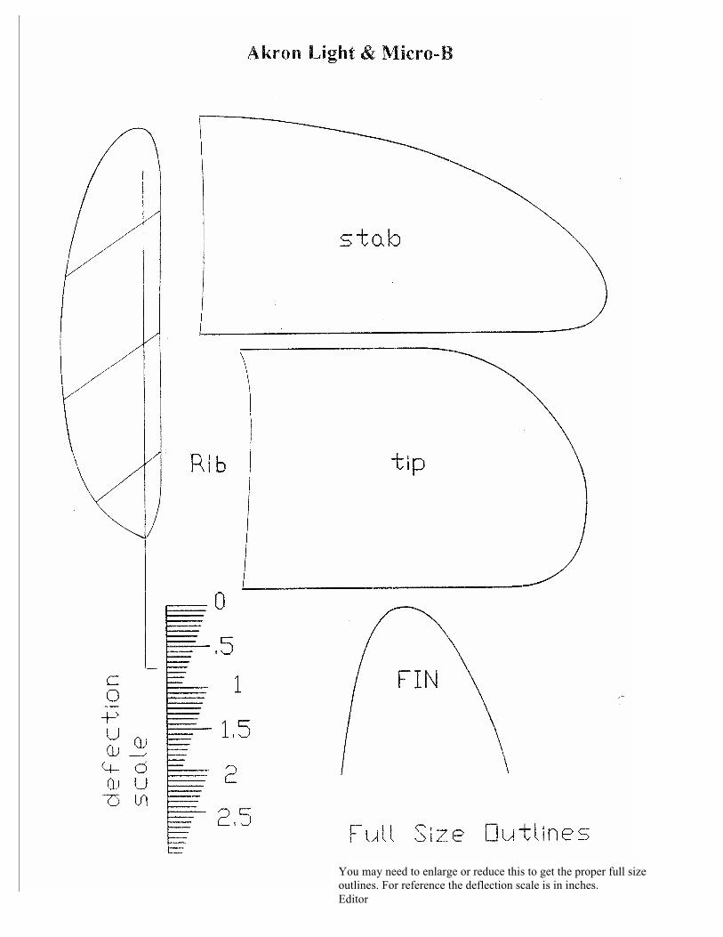
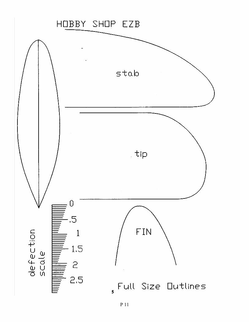
P 22You may need to enlarge or reduce this to get the proper full sizeoutlines. For reference the deflection scale is in inches.Editor
P 23
P 24
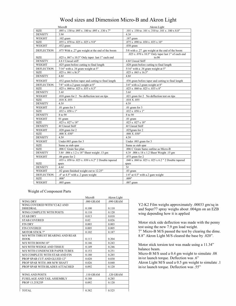
Wood sizes and Dimension Micro-B and Akron Light
Weight of Component Parts
MicroB Akron LightSIZE .095 x .130 to .095 x .180 to .095 x .130 x 7" .101 x .150 to .101 x .310 to .101 x .180 x 8.8"DENSITY 3.9# 4.3#WEIGHT .102 gram .187 gramSIZE .055 x .070 to .025 x .025 x 9.8" .075 x .090 to .030 x .035 x 10"WEIGHT .032 gram .038 gram
DEFLECTION .075 With a .27 gm weight at the end of the boom 5/8 with a .27. gm weight at the end of the boom
SIZE .025 x .067 x 10.5" Only taper last 1" each end.025 x .070 x 10.5" Only taper last 1" of each end
to.06DENSITY 4.8 # Unreal stiff 4.8# Unreal StiffWEIGHT .025 gram before cutting to final length .028 gram before cutting to final lengthDEFLECTION 7/16" with a .34 gram weight at 5" 5/16" with a .34 gram weight at 5"SIZE .025 x .061 x l6.5" .025 x .065 x 16.5"DENSITY 4.8# 4.8#
WEIGHT .032 gram before taper and cutting to final length .036 gram before taper and cutting to final lengthDEFLECTION 7/8" with a.2 gram weight at 8" 3/4" with a.2 gram weight at 8"SIZE .025 x .060 to .025 x .035 x 8.5" .025 x .060 to .025 x .035 x 8"DENSITY 3.4# 3.6#WEIGHT .018 gram for 2 No deflection test on tips .021 gram for 2 No deflection test on tipsSIZE .018 X .055 .018 X .055DENSITY 4.5# 4.5#WEIGHT .01 gram for 3 .01 gram for 3SIZE .032 x .058 x 1" .032 x .058 x 1"DENSITY 8 to 9# 8 to 9#WEIGHT 01 gram .01 gramSIZE .023 x .027 x 18" .023 x .027 x 18"DENSITY 4# Unreal Stiff 4# Unreal StiffWEIGHT .020 gram for 2 .025gram for 2SIZE .008 X .030" .008 X .030"DENSITY 4.5# 4.5#WEIGHT Under.003 gram for 3 Under .003 gram for 3SIZE Same as stab spar Same as stab sparSIZE .006 C Grain See plan .006 C Grain Same outline as Micro-BDENSITY 3.8# .006 x 1.2 x 18" Sheet weight .13 gm 4.3# .006 x 18 x 1.2 Sheet Weight .15 gmWEIGHT .06 gram for 2 .075 gram for 2
SIZE.035 x .058 to .025 x .030 x 6.2" 2 Double tapered
spars.040 x .060 to .025 x .025 x 6.2 " 2 Double tapered
sparsDENSITY 4.6# 5#WEIGHT .02 gram finished weight cut to 12.25" .03 gramDEFLECTION .4" at 4.5" with a .2 gram weight 1/4" at 4.5" with a.2 gam weightSIZE .008" .009"WEIGHT .005 gram .007 gram
MicroB Akron LightWING DRY .080 GRAM .090 GRAMWING COVERED WITH Y2-K2 ANDDIHEDRAL 0.100 0.110WING COMPLETE WITH POSTS 0.110 0.120STAB DRY 0.013 0.018STAB COVERED 0.02 0.026FIN DRY 0.003 0.003FIN COVERED 0.005 0.005MOTOR STICK 7" 0.102 0.187M/S WITH THRUST BEARING AND REARHOOK 0.113 0.204M/S WITH BOOM 10" 0.146 0.243M/S WITH WEDGE AND TISSUE 0.149 0.246M/S WITH CONDENCER PAPER TUBES 0.153 0.251M/S COMPLETE WITH STAB AND FIN 0.180 0.285PROP SPAR CUT AND GLUED 12" 0.020 0.030PROP SPAR WITH .008 M/W SHAFT 0.026 0.040PROP SPAR WITH BLADES ATTACHED 0.092 0.120
WING AND POSTS .110 GRAM .120 GRAMFUSELAGE AND TAIL ASSEMBLY 0.180 0.285PROP 13.25X25P 0.092 0.120
TOTAL 0.382 0.525
Y2-K2 Film weighs approximately .00033 gm/sq inand Super77 spray weighs about .004gm on an EZBwing depending how it is applied
Motor stick side deflection was made with the pennytest using the new 7.9 gm load weight.7” Micro-B M/S passed the test by clearing the dime.8.8” Akron Light M/S cleared the base by .020”.
Motor stick torsion test was made using a 11.34”balance beam.Micro-B M/S used a 0.4 gm weight to simulate .08in/oz launch torque. Deflection was .6”Akron Light M/S used a 0.5 gm weight to simulate .1in/oz launch torque. Deflection was .55”
P 25
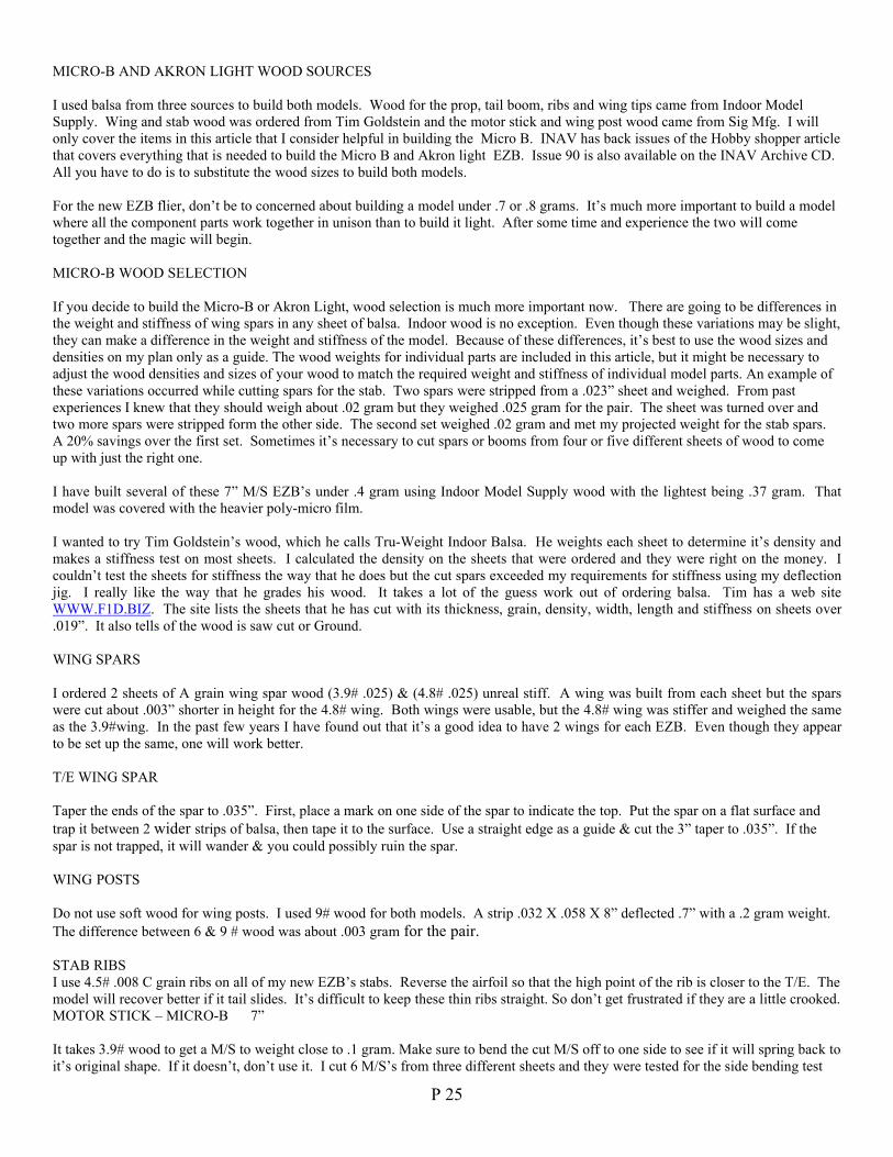
MICRO-B AND AKRON LIGHT WOOD SOURCES
I used balsa from three sources to build both models. Wood for the prop, tail boom, ribs and wing tips came from Indoor ModelSupply. Wing and stab wood was ordered from Tim Goldstein and the motor stick and wing post wood came from Sig Mfg. I willonly cover the items in this article that I consider helpful in building the Micro B. INAV has back issues of the Hobby shopper articlethat covers everything that is needed to build the Micro B and Akron light EZB. Issue 90 is also available on the INAV Archive CD. All you have to do is to substitute the wood sizes to build both models.
For the new EZB flier, don’t be to concerned about building a model under .7 or .8 grams. It’s much more important to build a modelwhere all the component parts work together in unison than to build it light. After some time and experience the two will cometogether and the magic will begin.
MICRO-B WOOD SELECTION
If you decide to build the Micro-B or Akron Light, wood selection is much more important now. There are going to be differences inthe weight and stiffness of wing spars in any sheet of balsa. Indoor wood is no exception. Even though these variations may be slight,they can make a difference in the weight and stiffness of the model. Because of these differences, it’s best to use the wood sizes anddensities on my plan only as a guide. The wood weights for individual parts are included in this article, but it might be necessary toadjust the wood densities and sizes of your wood to match the required weight and stiffness of individual model parts. An example ofthese variations occurred while cutting spars for the stab. Two spars were stripped from a .023” sheet and weighed. From pastexperiences I knew that they should weigh about .02 gram but they weighed .025 gram for the pair. The sheet was turned over andtwo more spars were stripped form the other side. The second set weighed .02 gram and met my projected weight for the stab spars. A 20% savings over the first set. Sometimes it’s necessary to cut spars or booms from four or five different sheets of wood to comeup with just the right one.
I have built several of these 7” M/S EZB’s under .4 gram using Indoor Model Supply wood with the lightest being .37 gram. Thatmodel was covered with the heavier poly-micro film.
I wanted to try Tim Goldstein’s wood, which he calls Tru-Weight Indoor Balsa. He weights each sheet to determine it’s density andmakes a stiffness test on most sheets. I calculated the density on the sheets that were ordered and they were right on the money. Icouldn’t test the sheets for stiffness the way that he does but the cut spars exceeded my requirements for stiffness using my deflectionjig. I really like the way that he grades his wood. It takes a lot of the guess work out of ordering balsa. Tim has a web siteWWW.F1D.BIZ. The site lists the sheets that he has cut with its thickness, grain, density, width, length and stiffness on sheets over.019”. It also tells of the wood is saw cut or Ground.
WING SPARS
I ordered 2 sheets of A grain wing spar wood (3.9# .025) & (4.8# .025) unreal stiff. A wing was built from each sheet but the sparswere cut about .003” shorter in height for the 4.8# wing. Both wings were usable, but the 4.8# wing was stiffer and weighed the sameas the 3.9#wing. In the past few years I have found out that it’s a good idea to have 2 wings for each EZB. Even though they appearto be set up the same, one will work better.
T/E WING SPAR
Taper the ends of the spar to .035”. First, place a mark on one side of the spar to indicate the top. Put the spar on a flat surface andtrap it between 2 wider strips of balsa, then tape it to the surface. Use a straight edge as a guide & cut the 3” taper to .035”. If thespar is not trapped, it will wander & you could possibly ruin the spar.
WING POSTS
Do not use soft wood for wing posts. I used 9# wood for both models. A strip .032 X .058 X 8” deflected .7” with a .2 gram weight. The difference between 6 & 9 # wood was about .003 gram for the pair.
STAB RIBSI use 4.5# .008 C grain ribs on all of my new EZB’s stabs. Reverse the airfoil so that the high point of the rib is closer to the T/E. Themodel will recover better if it tail slides. It’s difficult to keep these thin ribs straight. So don’t get frustrated if they are a little crooked.MOTOR STICK – MICRO-B 7”
It takes 3.9# wood to get a M/S to weight close to .1 gram. Make sure to bend the cut M/S off to one side to see if it will spring back toit’s original shape. If it doesn’t, don’t use it. I cut 6 M/S’s from three different sheets and they were tested for the side bending test
P 26
with the new 7.9 gram weight. All but 1 of the M/S’s passed the test without moving the dime. The torsional twist test was made witha .4 gram weight to represent .08 in. oz. Of winding torque and regestered a .6” deflection. This is a new test and I do know that a .6”reading is good on an 8.5” M/S.
TAIL BOOM 9.8’’
The boom that I used for the prototype might be a little stiff for the model weight. A boom that deflects 1” would be good for ceilingsup to 50 feet, because the launch torque will be much lower.
THRUST BEARING .008” MUSIC WIRE
Make the T/B .250” high and .175” from the front to the rear of the pigtail. Insert the bearing in the M/S so that the prop shaft is nomore than .12” below the bottom of the M/S. See hobby shopper article for bearing installation.
PROP SHAFT .008” MUSIC WIRE
Make the hook small because there is very little clearance under the M/S.
REAR HOOK
I call this a cheater hook because it adds .1” to the length of the M/S. Use .007 wire and make it as shown on the plan.
PROP SPAR DOUBLE TAPERED
For this model cut the spar at the hub higher than the width for a better flair. The finished spar should not weigh any more than .02gram and .025 gram with the .008 M/W hook.
PROP BLADES
To build a prop that weights under .1 gram you will need a sheet of .006” C grain that weights .13 gram or under. Don’t cut down onthe blade area to make the prop lighter. It needs the area and flair to keep the light model out of the ceiling. The finished prop is13.25” X 25P. The Hobby Shopper article goes into great detail on EZB prop construction. It’s a good idea to build 2 or 3 props forthe model. Make one with the spar mounted .1” from the blade T/E and the other .2” away. The third could be built with the blademounted right at the T/E. If the spar should be too stiff or too soft the blades can be removed and replaced on another spar withoutany weight gain. Soak the whole prop in slightly warm water for at least 30 minutes. Rotate the spar gently while the prop is in thewater and if the glue is soft enough the blades will fall off the spar. If not, re-soak for a while longer. Take a soft tooth brush andgently go over each spot that looks white until all of the glue is removed. Don’t rub hard or the balsa will tear. Rinse will and re-pitchthe blades. With some care, you can use the same blades over and over again. The cover picture shows a EZB with a symmetricalblade prop. Don’t use this type prop blade in low ceilings. The pitch has to be set too high to control the launch torque and the highpitch won’t utilize the cruse torque as well as a flairing prop.
SET UP AND TRIM
Follow the procedures in the Hobby Shopper Article, except for rubber sizes and torque readings. Always make a low power first flight to check themodels circle and nose high flight attitude.
RUBBER AND TORQUE RANGES
Depending on ceiling heights and air quality you can expect to use loops from 6.5” to 8” in length and .025 to.030” wide. The shorterloops use the wider cross sections to keep the torque up in low sites. In a 60 foot site a loop .025” X 8” would be better. You willhave to do a lot of test flying to come up with the right prop rubber combinations. Torque ranges will be around .04 to .05 in ceilingsto 50 feet and .07 for higher ceilings.
DEFLECTION JIG FROM HOBBY SHOPPER ARTICLE
If you plan on building the jig, use the full size deflection scale that is included in this article. The distance between the two dowels ofthe test piece holder was not shown on the drawing of the deflection gauge. That distance is 1.6” from the left side of the first dowel,to the 0 mark on the larger dowel. Also, it’s best to place a music wire stand off along the L/E of the deflection scale support. It keepsthe spar from flexing away from the scale face.
P 27
NO TOUCH CONTEST
The Micro B was originally designed for no touch flying, so it’s perfect for this kind of contest. The contest is flown in rounds with aminimum and maximum flight time for each round. If the model touches the ceiling during any round it’s out of the contest.Depending on the flying skills of the group, the first round could be set at 7 minutes with a maximum of 9 minutes. The next roundmight be 9 minutes and so on. The more experienced fliers could be handicapped with a higher flight time per round. This type offlying really improves your skills in selecting the correct rubber size, prop pitch and torque requirements for each flight. This kind ofevent can be used with any type of indoor model.
GOOD LUCK
Larry Coslick
Revision of the Hobby Shopper EZB Motor Stick Test
There were several articles in the INAV issue 105 directed toward my testing procedure for EZB motor sticks. After reading thearticles, I decided to re-test my M/S’s using the same procedure as described in the Hobby Shopper article, ISSUE 90
After the M/S’s were re-tested, it was obvious that there was a flaw in the way that the original test was made. The Hobby ShopperM/S test was designed just for that article and for the M/S’s that were cut for the prototype. The problem was that I didn’t compare thepenny test with my side-bending jig. My jig uses a mechanism that is not available to the public so I had to come up with an easierway to test the M/S’s. I happened to select a stiff piece of balsa for the prototype and didn’t realize it by using the new test. I wouldhave detected the wood’s stiffness by using my jig had a comparison test been made. After the article was completed the penny testwas put away and never given a thought until issue 105.
My side-bending jig uses a spring-loaded center post that drives a pointer along a numbered scale from 0 to 30. Readings in the rangeof 10 to 20 indicate a usable M/S. 10 being the stiffest. These numbers have no numerical value and are only used to compare onestick against another. I was able to measure the deflection and came up with a weight that would compare with my jig’s readings. Thenew weight uses a dime, quarter combination with a balsa handle and weighs 7.9 gram.
I re-tested 10 M/S’s using the penny test with the new weight and concluded that any M/S that clears the base will work.
The 10 M/S’s that were tested range in length from 8.5” to 9” and weigh .16 to .19 gram.
•Cut on computer controlled equipment•Every sheet individually graded and marked•Sheets >.020” tested and marked for stiffness•You pick your specific sheets on the web•Every sheet you get is exactly what you ordered
http://www.F1D.biz
Condenser tissueHuge 21.5” wide x 25 foot roll only US$15.00On a .838” OD .022” wall clear plastic tube with end caps.• Used tube makes a great blast tube or storage container.• tissue weighs .6 gm per 100 sq inches.
Shipping unlimited # of rollsUSA $4.50, can not ship to non-USA addressed due to package length
Tim Goldstein [email protected] W. Cross Dr Order via PayPal atLittleton CO 80127 www.IndoorDuration.com
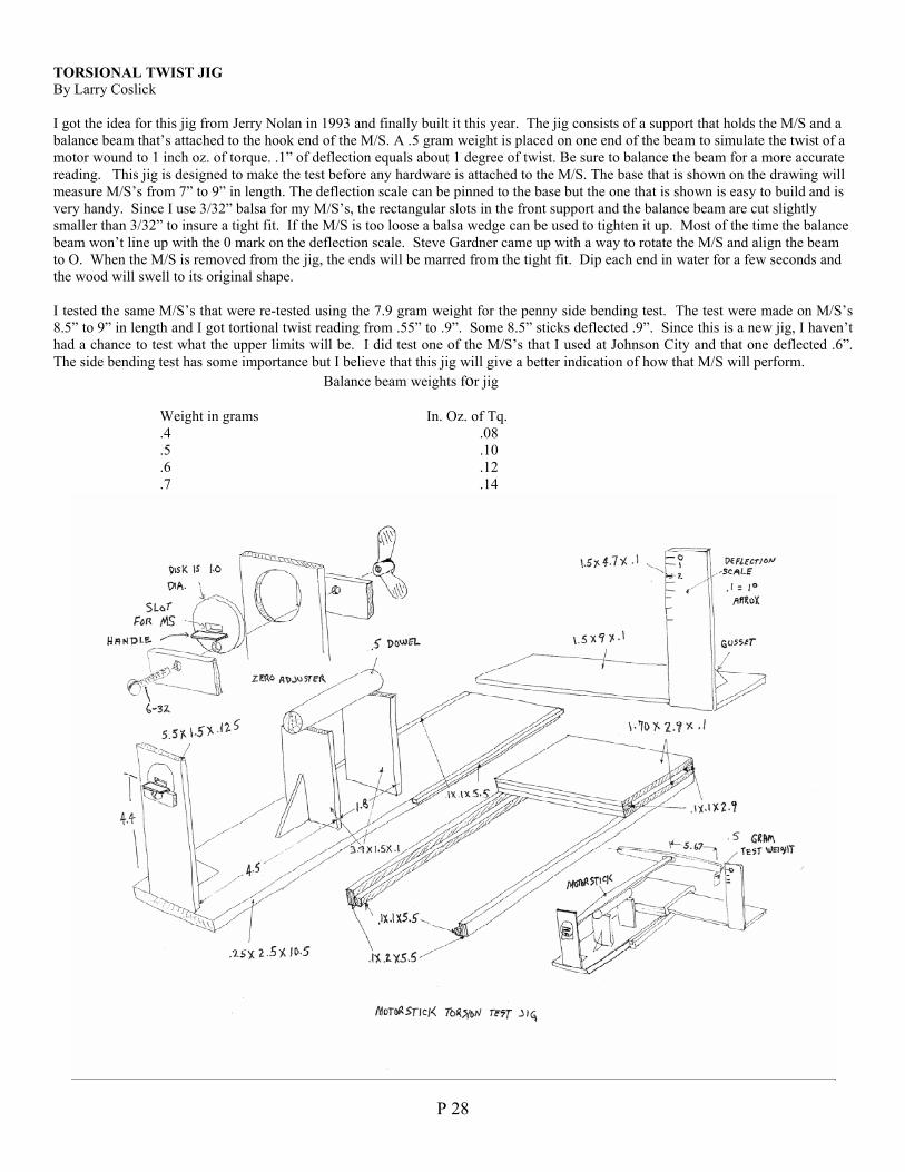
P 28
TORSIONAL TWIST JIGBy Larry Coslick
I got the idea for this jig from Jerry Nolan in 1993 and finally built it this year. The jig consists of a support that holds the M/S and abalance beam that’s attached to the hook end of the M/S. A .5 gram weight is placed on one end of the beam to simulate the twist of amotor wound to 1 inch oz. of torque. .1” of deflection equals about 1 degree of twist. Be sure to balance the beam for a more accuratereading. This jig is designed to make the test before any hardware is attached to the M/S. The base that is shown on the drawing willmeasure M/S’s from 7” to 9” in length. The deflection scale can be pinned to the base but the one that is shown is easy to build and isvery handy. Since I use 3/32” balsa for my M/S’s, the rectangular slots in the front support and the balance beam are cut slightlysmaller than 3/32” to insure a tight fit. If the M/S is too loose a balsa wedge can be used to tighten it up. Most of the time the balancebeam won’t line up with the 0 mark on the deflection scale. Steve Gardner came up with a way to rotate the M/S and align the beamto O. When the M/S is removed from the jig, the ends will be marred from the tight fit. Dip each end in water for a few seconds andthe wood will swell to its original shape.
I tested the same M/S’s that were re-tested using the 7.9 gram weight for the penny side bending test. The test were made on M/S’s8.5” to 9” in length and I got tortional twist reading from .55” to .9”. Some 8.5” sticks deflected .9”. Since this is a new jig, I haven’thad a chance to test what the upper limits will be. I did test one of the M/S’s that I used at Johnson City and that one deflected .6”. The side bending test has some importance but I believe that this jig will give a better indication of how that M/S will perform.
Balance beam weights for jig
Weight in grams In. Oz. of Tq..4 .08.5 .10.6 .12.7 .14
P 29
2001/2002 INTERNATIONAL POSTAL CONTESTfrom 1st Oct 2001 to 31st March 2002
As I mentioned before there have been very few entries, several of them being flown in ceilings higher than Category 1(8metres or 26.25 ft.). Because of the difficulties with finding reliable fudge factors I decided not to use a fudge factor, butreport all times within the ceiling category that they were flown. The final results (31 March 02) are as follows;
F1L
Category 1Vlad Linardic, Toronto 12:24Harley Ellis, Toronto 12:21Ken Mark, Toronto 11:11
Category 2Akihiro Danjo, Kawaski, Japan 19:19
Category 4Bill Gowen, Tropicana Dome, Florida 16:56
F1M
Category 1Fabio Manieri, Rome, Italy 14:23Vlad Linardic, Toronto 13:06
Category 2Akihiro Danjo, Kawasaki, Japan 16:53
Category 4Bill Gowen, Tropicana Dome, Florida 16:08
FAC Peanut
Category 1Mike Thomas, Toronto Lacey M10 1:54Chris Brownhill, Toronto Lacey M10 1:34Stu Weckerly, Dearborn, MI Stout 2AT 1:13Gert Brendal, Enschede, Holland
Renard RSV 18-100 1:07Bill Henderson, Toronto Davis TX-1 1:02Bob Fisher, Toronto Piper Vagabond 0:35
Category 2Akihiro Danjo, Yokohama, Japan Andreason 1:12
FAC No-Cal
Category 1Mike Thomas, Toronto Hosler Fury 4:49Vlad Linardic, Toronto Cassutt Racer 3:25
Category 2Akihiro Danjo, Yokohama, Japan Lacey M10 5:06
Category 4Fred Rash, Johnson City White Monoplane 4:09
Congratulations to Akihiro Danjo who produced the highest times regardless of ceiling category in F1M, F1L and No-Cal.They were all flown under a category 2 ceiling. Congratulations also to Mike Thomaswho produced an amazing category 1 time of 1:54 in FAC Peanut, which was also the top time regardless of ceilingcategory. W. Henderson
Cargo Lifter Contest DatesDear friends,CargoLifter just gave the consent to two Indoor Contests dates: June 1rst and 2nd for German Trials F1D with comps inother classes on demand andSeptember 14th and 15th for the German Open Nationals in all FAI Classes. The German Open will be announced in theFAI calender as one of the new types of contestsapproved by the CIAM Plenary Meeting this year.
Gerhard WoebbekingHolstenstrasse 10822767 Hamburg/ GermanyTel.+49-40-3898310 [email protected]
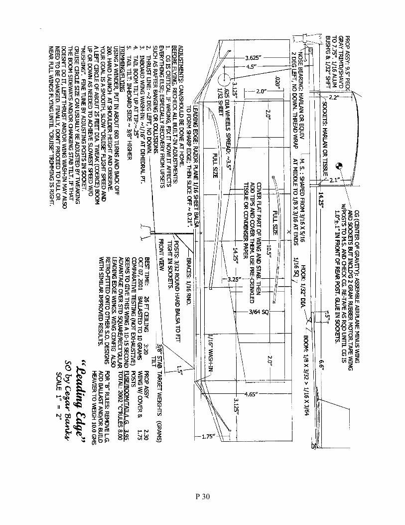
P 30
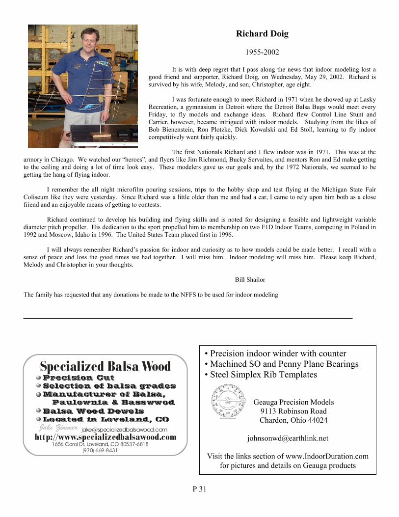
P 31
Richard Doig
1955-2002
It is with deep regret that I pass along the news that indoor modeling lost agood friend and supporter, Richard Doig, on Wednesday, May 29, 2002. Richard issurvived by his wife, Melody, and son, Christopher, age eight.
I was fortunate enough to meet Richard in 1971 when he showed up at LaskyRecreation, a gymnasium in Detroit where the Detroit Balsa Bugs would meet everyFriday, to fly models and exchange ideas. Richard flew Control Line Stunt andCarrier, however, became intrigued with indoor models. Studying from the likes ofBob Bienenstein, Ron Plotzke, Dick Kowalski and Ed Stoll, learning to fly indoorcompetitively went fairly quickly.
The first Nationals Richard and I flew indoor was in 1971. This was at thearmory in Chicago. We watched our “heroes”, and flyers like Jim Richmond, Bucky Servaites, and mentors Ron and Ed make gettingto the ceiling and doing a lot of time look easy. These modelers gave us our goals and, by the 1972 Nationals, we seemed to begetting the hang of flying indoor.
I remember the all night microfilm pouring sessions, trips to the hobby shop and test flying at the Michigan State FairColiseum like they were yesterday. Since Richard was a little older than me and had a car, I came to rely upon him both as a closefriend and an enjoyable means of getting to contests.
Richard continued to develop his building and flying skills and is noted for designing a feasible and lightweight variablediameter pitch propeller. His dedication to the sport propelled him to membership on two F1D Indoor Teams, competing in Poland in1992 and Moscow, Idaho in 1996. The United States Team placed first in 1996.
I will always remember Richard’s passion for indoor and curiosity as to how models could be made better. I recall with asense of peace and loss the good times we had together. I will miss him. Indoor modeling will miss him. Please keep Richard,Melody and Christopher in your thoughts.
Bill Shailor
The family has requested that any donations be made to the NFFS to be used for indoor modeling
Specialized Balsa Wood
http://[email protected]
Precision CutSelection of balsa gradesManufacturer of Balsa,
Paulownia & BasswwodBalsa Wood DowelsLocated in Loveland, CO
1656 Carol Dr, Loveland, CO 80537-6818(970) 669-8431
• Precision indoor winder with counter• Machined SO and Penny Plane Bearings• Steel Simplex Rib Templates
Geauga Precision Models9113 Robinson RoadChardon, Ohio 44024
Visit the links section of www.IndoorDuration.comfor pictures and details on Geauga products
400
350 150
250
A-- 82 5N SO
0
300DRN
HC
4
3R
OB I
91
1
4O
N3 200ODR
IO4
957 H
44
20
100
SIAGU
450
GE
A
P
0CER I
OM
DES
L
50NO
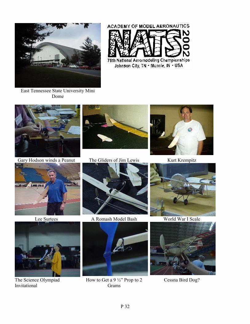
P 32
East Tennessee State University MiniDome
Gary Hodson winds a Peanut The Gliders of Jim Lewis Kurt Krempitz
Lee Surtees A Romash Model Bash World War I Scale
The Science OlympiadInvitational
How to Get a 9 ½” Prop to 2Grams
Cessna Bird Dog?
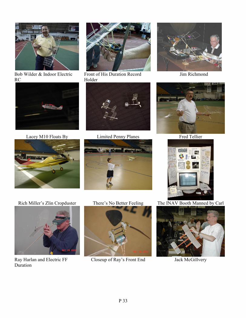
P 33
Bob Wilder & Indoor ElectricRC
Front of His Duration RecordHolder
Jim Richmond
Lacey M10 Floats By Limited Penny Planes Fred Tellier
Rich Miller’s Zlin Cropduster There’s No Better Feeling The INAV Booth Manned by Carl
Ray Harlan and Electric FFDuration
Closeup of Ray’s Front End Jack McGillvery
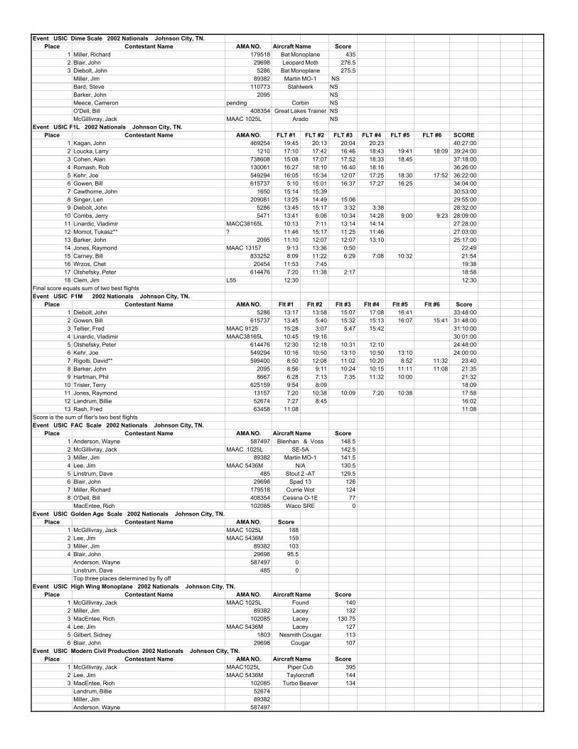
Event USIC Dime Scale 2002 Nationals Johnson City, TN.Place Contestant Name AMA NO. Aircraft Name Score
1 Miller, Richard 179518 4352 Blair, John 29698 276.53 Diebolt, John 5286 275.5
Miller, Jim 89382 NSBard, Steve 110773 NSBarker, John 2095 NSMeece, Cameron pending NSO'Dell, Bill 408354 NSMcGillivray, Jack MAAC 1025L NS
Event USIC F1L 2002 Nationals Johnson City, TN.Place Contestant Name AMA NO. FLT #1 FLT #2 FLT #3 FLT #4 FLT #5 FLT #6 SCORE
1 Kagan, John 469254 19:45 20:13 20:04 20:23 40:27:002 Loucka, Larry 1210 17:10 17:42 16:46 18:43 19:41 18:09 39:24:003 Cohen, Alan 738608 15:08 17:07 17:52 18:33 18:45 37:18:004 Romash, Rob 130061 16:27 18:10 16:40 18:16 36:26:005 Kehr, Joe 549294 16:05 15:34 12:07 17:25 18:30 17:52 36:22:006 Gowen, Bill 615737 5:10 15:01 16:37 17:27 16:25 34:04:007 Cawthorne, John 1650 15:14 15:39 30:53:008 Singer, Len 209081 13:25 14:49 15:06 29:55:009 Diebolt, John 5286 13:45 15:17 3:32 3:38 28:32:00
10 Combs, Jerry 5471 13:41 6:06 10:34 14:28 9:00 9:23 28:09:0011 Linardic, Vladimir MACC38165L 10:13 7:11 13:14 14:14 27:28:0012 Momot, Tukasz** ? 11:46 15:17 11:25 11:46 27:03:0013 Barker, John 2095 11:10 12:07 12:07 13:10 25:17:0014 Jones, Raymond MAAC 13157 9:13 13:36 0:50 22:4915 Carney, Bill 833252 8:09 11:22 6:29 7:08 10:32 21:5416 Wrzos, Chet 20454 11:53 7:45 19:3817 Olshefsky, Peter 614476 7:20 11:38 2:17 18:5818 Clem, Jim L55 12:30 12:30
Final score equals sum of two best flightsEvent USIC F1M 2002 Nationals Johnson City, TN.
Place Contestant Name AMA NO. Flt #1 Flt #2 Flt #3 Flt #4 Flt #5 Flt #6 Score1 Diebolt, John 5286 13:17 13:58 15:07 17:08 16:41 33:48:002 Gowen, Bill 615737 13:45 5:40 15:32 15:13 16:07 15:41 31:48:003 Tellier, Fred MAAC 9125 15:28 3:07 5:47 15:42 31:10:004 Linardic, Vladimir MAAC38165L 10:45 19:16 30:01:005 Olshefsky, Peter 614476 12:30 12:18 10:31 12:10 24:48:006 Kehr, Joe 549294 10:16 10:50 13:10 10:50 13:10 24:00:007 Rigotti, David** 599400 8:50 12:08 11:02 10:20 8:52 11:32 23:408 Barker, John 2095 8:56 9:11 10:24 10:15 11:11 11:08 21:359 Hartman, Phil 8667 6:28 7:13 7:35 11:32 10:00 21:32
10 Trisler, Terry 625159 9:54 8:09 18:0911 Jones, Raymond 13157 7:20 10:38 10:09 7:20 10:38 17:5812 Landrum, Billie 52674 7:27 8:45 16:0213 Rash, Fred 63458 11:08 11:08
Score is the sum of flier's two best flightsEvent USIC FAC Scale 2002 Nationals Johnson City, TN.
Place Contestant Name AMA NO. Aircraft Name Score1 Anderson, Wayne 587497 148.52 McGillivray, Jack MAAC 1025L 142.53 Miller, Jim 89382 141.54 Lee, Jim MAAC 5436M 130.55 Linstrum, Dave 485 129.56 Blair, John 29698 1267 Miller, Richard 179518 1248 O'Dell, Bill 408354 77
MacEntee, Rich 102085 0Event USIC Golden Age Scale 2002 Nationals Johnson City, TN.
Place Contestant Name AMA NO. Score1 McGillivray, Jack MAAC 1025L 1882 Lee, Jim MAAC 5436M 1593 Miller, Jim 89382 1034 Blair, John 29698 95.5
Anderson, Wayne 587497 0Linstrum, Dave 485 0Top three places determined by fly off
Event USIC High Wing Monoplane 2002 Nationals Johnson City, TN.Place Contestant Name AMA NO. Aircraft Name Score
1 McGillivray, Jack MAAC 1025L 1402 Miller, Jim 89382 1323 MacEntee, Rich 102085 130.754 Lee, Jim MAAC 5436M 1275 Gilbert, Sidney 1803 1136 Blair, John 29698 107
Event USIC Modern Civil Production 2002 Nationals Johnson City, TN.Place Contestant Name AMA NO. Aircraft Name Score
1 McGillivray, Jack MAAC1025L 3952 Lee, Jim MAAC 5436M 1443 MacEntee, Rich 102085 134
Landrum, Billie 52674Miller, Jim 89382Anderson, Wayne 587497
TaylorcraftTurbo Beaver
LaceyNesmith Cougar
Cougar
Piper Cub
Waco SRE
FoundLaceyLacey
Stout 2 -ATSpad 13
Currie WotCessna O-1E
Blenhan & VossSE-5A
Martin MO-1N/A
Great Lakes TrainerArado
Martin MO-1Stahlwerk
Corbin
Bat MonoplaneLeopard MothBat Monoplane
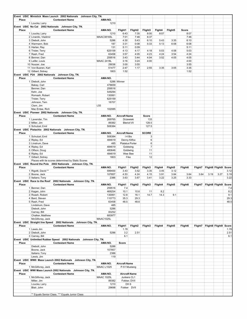
Event USIC Ministick Mass Launch 2002 Nationals Johnson City, TN.Place Contestant Name AMA NO.
1 Loucka, Larry 1210Event USIC No Cal 2002 Nationals Johnson City, TN.
Place Contestant Name AMA NO. Flight1 Flight2 Flight3 Flght4 Flight5 Score1 Loucka, Larry 1210 6:43 7:35 8:00 8:07 8:072 Linardic, Vladimir MAAC38165L 7:01 7:46 6:37 7:463 Diebolt, John 5286 4:30 5:43 6:10 5:43 3:35 6:104 Warmann, Bob 187 3:31 0:08 5:33 5:13 6:08 6:085 Harlan, Ray 131 5:11 0:09 5:116 Trisler, Terry 625159 4:13 4:17 4:18 5:03 4:58 5:037 Rash, Fred 63458 3:57 4:05 4:23 4:24 3:54 4:248 Benner, Dan 259516 3:43 3:44 4:04 3:52 4:05 4:059 Leifer, Louis MAAC 2418L 3:16 3:24 4:00 4:00
10 Nuszer, Joe 29036 3:00 3:55 3:5511 Von Bueren, Karl 51477 2:47 1:17 2:55 3:35 3:05 3:3512 Gilbert, Sidney 1803 1:52 1:52
Event USIC P24 2002 Nationals Johnson City, TN.Place Contestant Name AMA NO.
1 Diebolt, John 5286 WinnerBakay, Carl 478659Benner, Dan 259516Kehr, Joe 549294Romash, Robert 130061Trisler, Terry 625159Johnson, Tem 16707Clem, Jim L55Mac Entee, Rich 102085
Event USIC Pioneer 2002 Nationals Johnson City, TN.Place Contestant Name AMA NO. Aircraft Name Score
1 Lavender, Tim 269765 1332 Miller, Jim 89382 128.53 Schutzel, Emil 508384 127.5
Event USIC Pistachio 2002 Nationals Johnson City, TN.Place Contestant Name AMA NO. Aircraft Name SCORE
1 Schutzel, Emil 508384 32 Ripley, Ed 484619 63 Linstrum, Dave 485 64 Ripley, Ed 484619 75 Olfson, Doug 480646 116 Ripley, Ed 484619 117 Gilbert, Sidney 1803 12
Places with tie scores determined by Static ScoresEvent USIC Round the Pole 2002 Nationals Johnson City, TN.
Place Contestant Name AMA NO. Flight1 Flight2 Flight3 Flight4 Flight5 Flight6 Flight7 Flight8 Flight9 Score1 Rigotti, David ** 599400 3.43 3.52 3.35 3.45 3.12 3.122 Boone, Jack 107857 4.53 4.24 4.15 3.91 3.84 3.64 3.64 3.19 3.27 3.193 Italiano, Tony 2386 3.63 3.67 3.41 3.22 3.25 3.33 3.22
Event USIC Race to the Roof 2002 Nationals Johnson City, TN.Place Contestant Name AMA NO. Flight1 Flight2 Flight3 Flight4 Flight5 Flight6 Flight7 Flight8 Flight9 Score
1 Benner, Dan 259516 7.4 7.42 Kagan, John 469254 10.1 10.6 11 8.2 8.23 Roash, Robert 130061 12.8 16.1 14.7 14.3 9.1 9.14 Bard, Steven 110773 35.3 29.3 29.35 Rash, Fred 63458 48.5 48.6 48.5
Lindstrum, Dave 485Diebolt, John 5286Carney, Bill 83252Chalker, Matthew 683977McGillivray, Jack MAAC1025L
Event USIC Straight line Speed 2002 Nationals Johnson City, TN.Place Contestant Name AMA NO. Flight1 Flight2 Flight3 Flight4 Flight5 Flight6 Flight7 Flight8 Flight9 Score
1 Lewis.Jim 1.78 1.782 Diebolt, John 5286 3.2 2.51 2.513 Carney, Bill 6.1 6.1
Event USIC Unlimited Rubber Speed 2002 Nationals Johnson City, TN.Place Contestant Name AMA NO. Score
Diebolt, John 5286Boone, Jack 107857Italiano, Tony 2386Lewis, Jim 119
Event USIC WWII Mass Launch 2002 Nationals Johnson City, TN.Place Contestant Name AMA NO. Aircraft Name
1 McGillivray, Jack MAAC L1025Event USIC WWI Mass Launch 2002 Nationals Johnson City, TN.
Place Contestant Name AMA NO.1 McGillivray, Jack MAAC 1025L
Miller, Jim 89382Loucka, Larry 1210Blair, John 29698
** Equals Senior Class. *** Equals Junior Class
DH 6Fokker DVII
P-51 Mustang
Aircraft NameJunkers CL1Fokker, DVII
GoldwingGoldwingWee Bee
Fike
I 4 BisDenny Kitfox
Platatus Porter
DrzewiekiBleriot VII
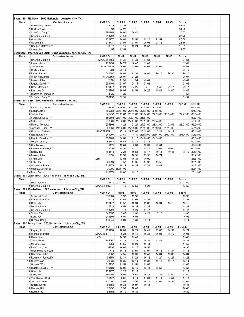
Event 201 HL Stick 2002 Nationals Johnson City, TN.Place Contstant Name AMA NO. FLT #1 FLT #2 FLT #3 FLT #4 Flt #5 Score
1 Richmond, James 4936 41:24 41:242 Chilton, Stan L30 24:28 31:15 34:283 Schaffer, Doug ** 680152 30:07 26:40 30:074 Linardic, Vladimir 714084 27:58 27:585 Grant, Jim 159477 10:09 23:58 19:10 22:54 23:586 Gowen, Bill 615737 21:59 21:51 20:03 23:16 23:167 Chalker, Matthew ** 683977 07:16 19:24 19:57 19:518 Clem, Jim L55 12:58 12:57
Event 202 Intermediate Stick 2002 Nationals Johnson City, TN.Place Contestant Name AMA NO. Flt #1 Flt #2 Flt #3 Flt #4 Flt #5 Score
1 Linardic, Vladimir MAAC381650 31:31 14:36 37:58 37:582 Kagan, John 469254 14:29 36:47 37:49 37:493 Tellier, Fred MAAC9125 29:09 08:04 35:01 34:07 35:014 Chilton, Stan L30 26:18 26:185 Rezac, Lauren 641807 10:08 19:39 10:03 26:13 24:38 26:136 Olschefsky, Peter MAAC864 25:07 24:23 25:077 Barker, John 2095 17:56 07:54 23:41 23:418 Rigotti, David ** 599400 21:57 08:15 23:02 23:029 Grant, James B. 159477 11:23 04:25 ATT 09:42 22:17 22:17
10 Kerr, Joe D. 549294 10:06 12:53 16:26 18:46 18:40 18:4611 Richmond, James W. 4936 07:35 37:5812 Schaffer, Doug ** 680152 05:31 05:31
Event 203 F1D 2002 Nationals Johnson City, TN.Place Contestant Name AMA NO. FLT #1 FLT #2 FLT #3 FLT #4 FLT #5 FLT #6 SCORE
1 Richmond, James 4936 27:46:00 30:33:00 31:43:00 33:04:00 64:49:002 Kagan, John 469254 31:34:00 29:45:00 32:38:00 31:55:00 64:33:003 Tellier, Fred 645957 28:12:00 28:57:00 30:14:00 27:59:00 30:50:00 29:47:00 61:04:004 Schaefer, Doug ** 680152 27:47:00 30:07:00 28:58:00 59:05:005 Saks, Ben ** 663661 25:06:00 27:47:00 29:17:00 29:24:00 58:41:006 Momot, Tomasz 675398 8:23 23:21 27:23:00 28:12:00 22:06 28:08:00 56:20:007 Johnson, Brian ** 643961 24:38:00 27:59:00 26:11:00 26:40:00 28:17:00 56:16:008 Linardic, Vladamir MAAC38165L 17:18 27:37:00 25:42:00 7:21 10:19 53:19:009 Rezac, Lauren 641807 23:55 8:49 25:12:00 25:41:00 24:31:00 24:06:00 50:52:00
10 Rigotti, David M ** 599400 23:51 21:17 24:23:00 24:13:00 48:38:0011 Leppard, Larry 93740 20:49 22:15 23:14 45:29:0012 Combs, Jerry 5471 19:54 8:38 19:36 20:54 40:48:0013 Raymond-Jones, D C 63358 19:52 15:27 15:28 19:09 20:45 40:38:0014 Ripley, Ed 484619 2:24 19:53 18:17 19:15 19:43 15:10 39:36:0015 Barker, John 2095 15:36 18:55 19:52 10:24 38:27:0016 Clem, Jim L55 12:58 16:31 19:00 35:31:0017 Kehr, Joe 549294 7:52 17:35 17:36 15:56 35:11:0018 Olshefsky, Peter 614476 15:15 14:22 17:21 15:48 34:58:0019 Cailliau, Lawrence 79985 28:14:00 28:14:0020 Bard, Steve 110773 13:02 13:17 26:19:00
Event 204 Cabin ROG 2002 Nationals Johnson City, TN.Place Name AMA NO. FLT #1 FLT #2 FLT #3 FLT #4 FLT #5 Score
1 Loucka, Larry 1210 24:47:00 24:47:002 Linardic, Vladimir MAAC38165L 7:45 13:59 9:21 13:59
Event 205 Manhattan 2002 Nationals Johnson City, TN.Place Contestant Name AMA NO. Flt #1 Flt #2 FLT #3 FLT #4 FLT #5 Score
1 Schutzel, Emil 508384 9:37 13:35 13:352 Van Gorder, Walt 19912 11:59 12:04 13:26 13:263 Grant, Jim 159477 11:52 10:34 12:02 10:34 13:15 13:154 Loucka, Larry 1210 9:56 10:35 12:24 12:245 Linardic, Vladimir 714084 4:44 8:32 11:47 11:476 Tellier, Fred 645957 7:47 9:33 8:20 7:12 9:337 Kehr, Joe 549294 6:51 6:59 6:598 Oleson, Doug 490646 2:09 1:39 2:14 2:14
Event 207 Pennyplane 2002 Nationals Johnson City, TN.Place Contestant Name AMA NO. FLT #1 FLT #2 FLT #3 FLT #4 FLT #5 SCORE
1 Kagan, John 469254 18:00 18:24 16:41 17:07 16:58 18:242 Olshefsky, Peter MAAC864 9:22 10:41 10:32 16:08 15:19 16:083 Clem, Jim L-55 14:30 15:48 15:484 Teller, Fred 645957 13:18 8:18 15:31 13:41 15:315 Cawthorne, J. 1650 14:55 13:00 13:44 14:556 Richmond, Jim 4936 14:00 13:15 14:39 14:397 Wisniewski, Gordon 716 14:16 13:51 13:07 10:15 11:37 14:168 Hartman, Phillip 8667 4:55 13:33 13:48 14:04 13:08 14:049 Raymond-Jones, DC 63358 12:30 13:28 10:12 13:27 12:25 13:28
10 Nuszer, Joe 29036 12:36 13:14 12:38 12:13 12:17 13:1411 Gowen, Wm 615737 11:58 11:51 13:06 13:0612 Rigotti, David M ** 599400 12:01 12:46 12:43 12:55 12:5513 Grant, Jim 159477 3:20 12:19 12:1914 Kehr, Joe 549294 9:05 9:57 10:15 4:31 11:50 11:5015 Von Bueren, Karl 51477 9:01 9:43 11:09 11:13 6:51 11:1316 Johnson, Tem 167007 9:04 9:55 10:23 11:03 10:56 11:0317 Rigotti, David 66859 10:38 10:07 10:48 10:4818 Carney, Bill 83252 2:50 10:40 10:4019 Rash, Fred 63458 10:10 10:39 10:39
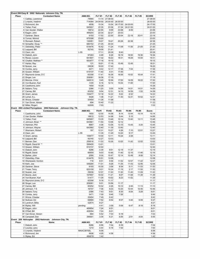
Event 206 Easy B 2002 Nationals Johnson City, TN.Place Contestant Name AMA NO. FLT #1 FLT #2 FLT #3 FLT #4 FLT #5 SCORE
1 Cailliau, Lawrence 79985 11:14 27:38:00 27:38:002 Linardic, Vladimir 714084 24:04:00 24:00:00 26:00:00 26:00:003 Richmond, Jim 4936 15:34 10:54 24:17:00 24:03:00 24:17:004 Tellier, Fred 645957 22:35 23:58 21:54 24:01:00 24:01:005 Van Gorder, Walter 19912 22:55 9:09 23:58 8:05 23:586 Kagan, John 469254 22:34 22:27 23:53 23:537 Gardner, Steve 6193 17:02 22:00 20:04 23:18 20:41 23:188 Tomaz, Momot 675398 23:00 23:009 Romash, Robert 130061 19:07 19:47 20:26 22:38 22:38
10 Schaefer, Doug ** 680152 21:25 20:34 21:2511 Olshefsky, Peter 614476 16:42 11:24 11:09 11:55 21:00 21:0012 Leppard, Bill 93740 19:09 21:41 20:4113 Clem, Jim L-55 17:11 20:28 8:40 20:2814 Diebolt, John 97263 4:48 6:26 18:19 18:50 19:36 19:3615 Rezac, Lauren 641807 17:32 16:22 19:31 19:29 15:50 19:3116 Chalker, Mathew ** 683977 17:18 19:15 19:1517 Harlan, Ray 131 18:51 17:19 10:49 12:45 18:5118 Nuszer, Joe 29036 18:20 17:42 18:2019 Combs, Jerry 5471 9:42 12:17 17:58 7:04 17:5820 Gowen, William 615737 11:40 4:31 17:45 17:4521 Raymond-Jones, D C 63358 17:41 16:39 16:56 15:52 16:44 17:4122 Singer, Len 209081 16:36 17:18 17:1823 Morrow, Chris 546510 3:45 16:56 17:00 14:09 16:22 17:0024 Von Bueren, Karl 0:00 6:18 12:14 15:54 17:00 17:0025 Cawthorne,John 1650 15:26 15:2626 Italiano, Tony 2386 11:20 3:05 14:59 14:51 14:51 14:5927 Carney, Bill 83252 9:04 12:31 14:13 14:59 1:52 14:5928 Grant, James 159477 12:18 14:22 5:02 6:52 14:2229 Lemel, A.L. 5028 1:38 11:21 11:40 12:31 10:02 12:3130 Wrzos, Chester 20454 11:28 11:58 11:5831 Van Dover, Abram 894 10:40 11:22 11:2232 Miller, Roger) 52009 7:03 7:03
Event 208 Limited Pennyplane 2002 Nationals Johnson City, TN.Place Contestant Name AMA NO. Flt #1 Flt #2 Flt #3 Flt #4 Flt #5 Score
1 Cawthorne, John 1650 12:30 14:58 8:14 13:44 15:14 15:142 Van Gorder, Walter 19912 12:53 14:06 5:44 5:15 14:063 Tellier, Fred 645957 13:35 13:48 10:14 13:40 13:11 13:484 Johnson, Brian ** 643961 11:50 13:06 12:12 13:465 Hartman, Phil 8667 4:36 13:26 13:10 13:45 3:20 13:456 Johnson, Wayne 643960 12:40 11:39 13:40 13:407 Warmann, Robert 187 12:31 13:27 4:26 7:10 12:51 13:278 Clem, Jim L-55 11:35 11:45 13:20 5:17 13:209 Grant, James 159477 10:00 13:11 10:24 2:28 13:11
10 Leppard, Bill 93740 12:27 13:03 13:0311 Benner, Dan 259516 11:03 10:35 13:02 11:42 12:02 13:0212 Rigotti, David M ** 599400 13:01 13:0113 Gowen, William 615737 12:40 12:4014 Diebolt, John 5286 4:39 9:51 12:19 11:37 12:1915 Rigotti, David 66859 9:03 10:46 11:40 12:16 11:46 12:1616 Barker, John 2095 9:30 10:47 12:14 10:48 9:06 12:1417 Olshefsky, Pete 614476 10:51 12:08 12:0818 Wisniewski, Gordon 716 8:51 9:56 11:52 12:07 11:22 12:0719 Kehr, Joe 549294 11:51 9:26 11:35 11:43 12:06 12:0620 Gardner, Steve 6193 10:30 3:58 9:34 5:11 11:53 11:5321 Trisler, Terry 625159 9:51 10:34 11:19 2:17 11:50 11:5022 Nuszer, Joe 29036 12:07 11:42 11:30 11:40 11:09 11:4223 Boone, Jack 107857 10:02 11:21 9:07 11:08 11:39 11:3924 Von Bueren, Karl 51477 11:39 10:02 8:23 11:02 11:3925 Raynond-Jones, D C 63358 9:16 11:17 11:1726 Singer, Len 209081 9:01 10:56 11:17 11:1727 Carney, Bill 83252 10:52 4:26 10:12 2:46 11:13 11:1328 Johnson, T E 16707 7:36 9:23 10:20 10:44 10:46 10:4629 Italiano, Tony 2386 7:43 9:51 8:30 6:54 3:29 9:5130 Combs, Jerry 5471 7:59 9:46 7:56 9:4631 Wrzos, Chester 20454 7:49 9:42 9:4232 Sullivan, Ed 69585 7:52 8:54 9:37 3:40 6:59 9:3733 Landrum, Billie 52674 8:27 8:2734 Ripley, Will pending 4:41 3:59 5:06 6:47 8:18 8:1835 Kagan, John 469854 7:24 8:01 8:0136 O'Dell, Bill 408354 7:24 8:01 8:0137 Van Dover, Abram 894 5:52 7:03 6:18 7:0338 Campbell, Dan 346641 3:39 5:31 5:55 2:51 4:54 5:55
Event 209 Helicopter 2002 Nationals Johnson City, TN.Place Name AMA NO. FLT #1 FLT #2 FLT #3 FLT #4 FLT #5 SCORE
1 Diebolt, John 5286 6:56 7:04 6:39 7:042 Loucka, Larry 1210 5:44 6:16 7:00 7:003 Linardic, Vladimir MAAC38165L 6:58 6:584 Richmond, Jim 4936 4:05 4:36 4:365 Ripley, Ed 484619 1:42 1:42
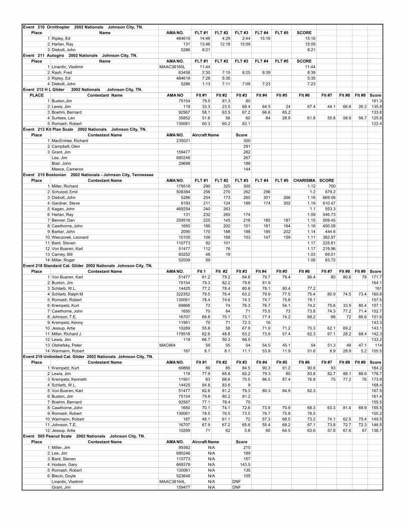
Event 210 Ornithopter 2002 Nationals Johnson City, TN.Place Name AMA NO. FLT #1 FLT #2 FLT #3 FLT #4 FLT #5 SCORE
1 Ripley, Ed 484619 14:46 4:29 2:44 15:16 15:162 Harlan, Ray 131 13:46 12:18 15:09 15:093 Diebolt, John 5286 8:21 8:21
Event 211 Autogiro 2002 Nationals Johnson City, TN.Place Name AMA NO. FLT #1 FLT #2 FLT #3 FLT #4 FLT #5 SCORE
1 Linardic, Vladimir MAAC38165L 11:44 11:442 Rash, Fred 63458 2:30 7:15 8:25 8:39 8:393 Ripley, Ed 484619 7:28 5:35 5:354 Diebolt, John 5286 1:13 7:11 7:09 7:23 7:23
Event 212 H L Glider 2002 Nationals Johnson City, TN.PLACE Contestant Name AMA NO Flt #1 Flt #2 Flt #3 Flt #4 Flt #5 Flt #6 Flt #7 Flt #8 Flt #9 Score
1 Buxton,Jim 75154 79.5 81.3 80 161.32 Lewis, Jim 119 33.3 23.5 68.4 64.5 24 67.4 44.1 66.8 26.2 135.83 Boehm, Bernard 92567 58.1 63.5 67.2 66.6 65.2 133.84 Surtees, Len 35852 51.6 56 60 64 28.9 61.8 55.8 58.9 56.7 125.85 Romash, Robert 130061 60.3 60.2 62.1 122.4
Event 213 Kit Plan Scale 2002 Nationals Johnson City, TN.Place Contestant Name AMA NO. Aircraft Name Score
1 MacEntree, Richard 235021 3002 Campbell, Glen 2913 Grant, Jim 159477 282
Lee, Jim 680246 267Blair, John 29698 188Meece, Cameron 144
Event 215 Bostonian 2002 Nationals - Johnson City, TennesseePlace Contestant Name AMA NO. FLT #1 FLT #2 FLT #3 FLT #4 FLT #5 CHARISMA SCORE
1 Miller, Richard 179518 290 325 300 1.12 7002 Schutzel, Emil 508384 256 270 262 296 1.2 679.23 Diebolt, John 5286 254 173 260 301 266 1.18 669.064 Gardner, Steve 6193 211 124 189 174 302 1.19 610.475 Kagan, John 469254 240 263 1.1 553.36 Harlan, Ray 131 232 265 174 1.09 546.737 Benner, Dan 259516 225 145 218 185 187 1.15 509.458 Cawthorne, John 1650 186 202 101 181 164 1.16 450.089 Barker, John 2095 170 188 188 185 202 1.14 444.6
10 Wieczorek, Leonard 10105 109 168 103 147 159 1.11 362.9711 Bard, Steven 110773 92 101 1.17 225.8112 Von Bueren, Karl 51477 112 76 1.17 219.9613 Carney, Bill 83252 48 19 1.03 69.0114 Miller, Roger 52009 59 1.08 63.72
Event 218 Standard Cat. Glider 2002 Nationals Johnson City, TN.Place Contestant Name AMA NO. Flt 1 Flt #2 Flt #3 Flt #4 Flt #5 Flt #6 Flt #7 Flt #8 Flt #9 Score
1 Von Bueren, Karl 51477 81.2 79.2 84.8 79.7 78.4 86.4 80 80.6 78 171.72 Buxton, Jim 75154 79.3 82.2 79.8 81.9 164.13 Schlarb, W.L. 14425 77.2 78.4 80.6 78.1 80.4 77.2 1614 Schlarb, Ralph M 322352 79.5 78.4 63.2 79.9 77.5 75.4 80.9 74.5 73.4 160.85 Romash, Robert 130061 78.4 74.6 74.3 74.7 75.8 79.1 157.56 Krempetz, Kurt 69866 73 74 76.3 76.7 54.1 74.2 75.6 33.9 80.4 157.17 Cawthorne, John 1650 70 64 71 75.5 73 73.8 74.3 77.2 71.4 152.78 Johnson, T.E. 16707 69.8 70.1 73.1 77.4 74.2 68.2 66 72 66.6 151.69 Krempetz, Kenny 11951 70 71 72.3 16 143.3
10 Jessup, Artie 10269 55.8 58 67.9 71.9 71.2 70.3 62.1 69.2 143.111 Miller, Richard J. 179518 62.6 48.8 63.2 73.9 57.4 62.3 67.1 28.2 68.4 142.312 Lewis, Jim 119 66.7 50.3 66.5 133.213 Olshefsky, Peter MAC864 59 55 54 54.5 45.1 54 51.3 48 47.1 11414 Warmann, Robert 187 8.1 8.1 11.1 53.9 11.9 51.6 8.9 28.9 5.2 105.5
Event 219 Unlimited Cat. Glider 2002 Nationals Johnson City, TN.Place Contestant Name AMA NO. Flt #1 Flt #2 Flt #3 Flt #4 Flt #5 Flt #6 Flt #7 Flt #8 Flt #9 Score
1 Krempetz, Kurt 69866 89 85 84.5 90.3 91.2 90.6 93 184.22 Lewis, Jim 119 77.9 65.8 82.2 79.3 80 83.8 82.7 88.1 88.6 176.73 Krempetz, Kenneth 11951 83 68.6 70.5 86.5 87.4 76.8 75 77.2 76 173.94 Schlarb, W.L. 14425 84.8 83.6 9 168.45 Von Bueren, Karl 51477 82.6 81.2 79.3 80.3 84.9 82.3 167.56 Buxton, Jim 75154 79.8 80.2 81.2 161.47 Boehm, Bernard 92567 77.1 78.4 75 155.58 Cawthorne, John 1650 70.1 74.1 72.6 73.9 70.9 68.3 63.3 81.4 69.9 155.59 Romash, Robert 130061 78.5 76.5 73.5 76.7 75.8 76.5 155.2
10 Warmann, Robert 187 48.1 61.1 72 57.3 68.5 73.2 74.1 62.5 75.4 149.511 Johnson, T.E. 16707 67.9 67.2 65.6 55.4 68.2 67.1 73.8 72.7 72.3 146.512 Jessup, Artie 10269 71 62 0.8 60 64.5 63.6 57.8 67.6 67 138.7
Event 505 Peanut Scale 2002 Nationals Johnson City, TN.Place Contestant Name AMA NO. Aircraft Name Score
1 Miller, Jim 89382 2102 Lee, Jim 680246 1893 Bard, Steven 110773 1574 Hodson, Gary 669378 143.55 Romash, Robert 130061 1356 Blevin, Doyle 523646 105
Linardic, Vladimir MAAC38164L DNFGrant, Jim 159477 DNF
N/AN/AN/AN/AN/AN/AN/AN/A
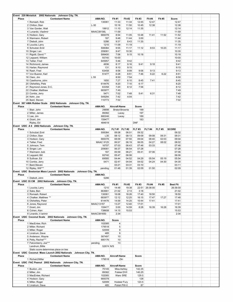
Event 220 Ministick 2002 Nationals Johnson City, TN.Place Contestant Name AMA NO. Flt #1 Flt #2 Flt #3 Flt #4 Flt #5 Score
1 Romash, Rob 130061 11:33 11:34 12:45 12:47 12:472 Chilton, Stan L-30 10:18 11:50 10:45 12:38 12:383 Van Gorder, Walt 19912 11:10 12:14 11:35 12:144 Lunardic, Vladimir MAAC38156L 11:59 11:595 Hodson, Gary 669378 8:54 11:05 10:48 11:41 11:52 11:526 Warmann, Robert 187 9:48 11:44 3:00 11:447 Diebolt, John 5286 9:37 8:43 11:35 11:358 Loucka, Larry 1210 11:09 11:19 11:199 Schutzel, Emil 508384 9:55 11:17 11:12 8:53 10:23 11:17
10 Singer, Len 209081 9:47 10:30 10:3011 Rigotti, David ** 599400 7:06 9:15 10:18 10:1812 Leppard, William 93740 10:00 10:0013 Tellier, Fred 645957 5:46 9:42 9:4214 Richmond, James 4936 8:17 9:16 9:41 9:18 9:4115 Harlan, Raymond 131 9:10 9:15 9:1516 Rash, Fred 63458 8:58 8:09 9:06 9:13 9:1317 Von Bueren, Karl 51477 6:28 8:51 7:46 6:22 6:22 8:5118 Clem, Jim L 55 8:50 7:54 8:5019 Cawthorne, John 1650 7:27 6:10 8:45 7:41 8:4520 Olshefsky, Pete 614476 8:20 7:10 6:17 8:2021 Raymond Jones, D.C. 63358 7:20 8:12 7:56 8:1222 Chalker, Matthew 683977 7:49 7:4923 Combs, Jerry 5471 7:02 7:48 5:41 6:31 7:4824 Kehr, Joe 549294 7:42 4:04 7:4225 Bard, Steven 110773 7:02 7:02
Event 507 AMA Rubber Scale 2002 Nationals Johnson City, TN.Place Contestant Name AMA NO. Aircraft Name Score
1 Blair, John 29698 1992 Miller, James 89382 1973 Lee, Jim 680246 1894 Grant, Jim 159477 183
Ripley, Ed 484619 DNFEvent USIC A 6 2002 Nationals Johnson City, TN.
Place Contestant Name AMA NO. FLT #1 FLT #2 FLT #3 FLT #4 FLT #5 SCORE1 Schutzel, Emil 508384 08:08 06:51 09:32 09:322 Chilton, Stan L30 08:12 08:13 09:09 09:08 09:31 09:313 Hodson, Gary 669378 08:09 07:55 09:04 08:40 02:03 09:044 Tellier, Fred MAAC 9125 06:57 06:19 06:05 04:27 08:02 08:025 Johnson, Tem 16707 07:03 06:43 07:46 03:33 07:466 Singer, Len 209081 06:37 06:54 07:28 07:287 Warmann, bob 187 05:59 06:21 05:41 07:06 07:068 Leppard, Bill 93740 05:47 06:06 06:069 Sullivan, Ed 69585 04:44 04:52 04:29 05:54 05:19 05:54
10 Combs, Jerry 5471 02:47 04:04 04:02 04:24 04:30 04:3011 Bard,Steven 03:21 03:31 03:10 03:1112 Ripley, Will*** pending 01:48 01:39 02:09 01:50 02:09
Event USIC Bostonian Mass Launch 2002 Nationals Johnson City, TN.Place Contestant Name AMA NO.
1 Diebolt, John 5286Event USIC 35 CM 2002 Nationals Johnson City, TN.
Place Contestant Name AMA NO. Flt #1 Flt #2 Flt #3 Flt #4 Flt #5 Best Flt1 Loucka, Larry 1210 14:48 19:38 22:51 26:36:00 26:36:002 Saks, Ben 663661 21:02 2:13 3:18 21:023 Romash, Robert 130061 16:08 18:26 17:40 18:50 18:504 Chalker, Matthew ** 683977 12:12 12:25 16:15 17:47 17:27 17:485 Olshefsky, Peter 614476 14:59 14:25 10:44 17:41 17:416 Jones, Raynond MAAC13157 13:27 12:40 17:01 17:017 Grant, Jim 159477 5:00 14:59 8:28 16:39 16:28 16:398 Cohen, Alan 738608 14:15 15:53 15:539 Linardic, V.larimir MAAC381650 2:34 2:34
Event USIC Coconut Scale 2002 Nationals Johnson City, TN.Place Contestant Name AMA NO. Score
1 MacEntee, Rich 102085 42 Miller, Richard 179518 53 Miller, Roger 52009 94 Linstrum, Dave 485 95 Anderson, Wayne 587497 106 Petty, Rachel*** 680176 107 Falconberry, Joe*** pending 13
Landrum, Billie 52674 N/SStatic score determines place on ties
Event USIC Coconut Mass Launch 2002 Nationals Johnson City, TN.Place Contestant Name AMA NO. Aircraft Name Score
1 Richard Miller 179518Event USIC FAC Peanut 2002 Nationals Johnson City, TN.
Place Contestant Name AMA NO. Aircraft Name Score1 Buxton, Jim 75145 142.252 Miller, Jim 89382 140.253 MacEntee, Richard 102085 129.54 Hodson, Gary 669378 1285 Miller, Roger 52009 123.56 Linstrum, Dave 485 87
Bristol BrownieLaceyLacey
Miss AshleyFokker DVIIWaro SRE
Hosleer FuryPolish PW-II
Ziln
P 40
INAV
1350
Ind
ep
end
enc
eSt
L ake
wo
od
CO
8021
5
IndoorM
odelSpecialties
Highquality,Lowprice
sTo
ols
from
Sca
les
toRu
bb
erS
trip
pe
rsM
ate
rialf
rom
Ultra
film
toTh
rust
Bea
ring
sBa
mb
ino
com
pe
titiv
eSc
ienc
eO
lym
pia
dm
odel
kit
See
my
bro
chur
eun
de
rLin
ksa
tht
tp://
ww
w.In
do
orD
ura
tion.
com
Ray
Ha
rlan
15H
ap
py
Ho
llow
Rd.
Wa
yla
nd,M
A01
778
(508
)358
-401
3MasterCard
and
VISA
accepted