Embed Size (px)
Citation preview
ISSN: 2278 – 909X International Journal of Advanced Research in Electronics and Communication Engineering (IJARECE)
Volume 4, Issue 6, June 2015
1811 All Rights Reserved © 2015 IJARECE
Abstract— In this paper design and implementation of signed,
unsigned and floating point multiplication of binary numbers has
been presented. In which integration of algorithms namely booth
and Wallace has been used to obtain faster and efficient
multiplication. The partial product generation and reduction
stages are optimized using booth and Wallace algorithms to
achieve higher rate of operation and making the system efficient.
The present work is done by Cadence virtuoso software, 180nm
technology for transistor level implementation and simulation is
done with the help of Cadence NC simulator to calculate area,
power and delay.
Index Terms—modified booth algorithm, Wallace structure,
floating point.
I. INTRODUCTION
In the todays scenario many processors, digital computers,
DSP applications, RISC and CISC devises are need of high
speed multiplier with more accurate results. Reducing the
time delay and power consumption are very essential
requirements for many applications.
Floating Point Numbers: meaning of floating point is derived
as there is no fixed numbers of digits before and after the
decimal point and the decimal point can be float. Multiplying
floating point numbers is a critical requirement for DSP
applications involving large dynamic range. In this paper
modified Booth Encoded Wallace tree Multiplier
implemented. The multiplication operation is one of the most
complex arithmetic operations as it involves a lot of additions
and carry propagations. There are three basic combinational
operations, which do the computation in our module is shown
in fig.1. Multiplication operation mainly results with the help
of given equation denotes Y=Mcand × Mplier, where Mcand
indicates multiplicand and Mplier indicates multiplier.
As com to designing part, we are designing signed, unsigned
and floating point multiplier where it includes exponent block
and mantissa block is shown in fig.1.
Shubha N, VLSI and embedded systems, Dr AIT, Bangalore, India.
Dr J S Baligar,Assosiate professor, ECE deportment, Dr.AIT college,
Bangalore, India.
Fig 1: Proposed block diagram
Mantissa block includes three steps and the first step is partial
product generation, in this paper we are using modified booth
algorithm which give N/2+1 partial product rows, where N
indicates number of bits. Second step is partial product
reduction stage is done by Wallace algorithm, on our design
compressors are using avoid many Full adders and half adders
so that area requirement is reducing and final is addition stage
is done by carry ripple adder. As come to exponent block
addition of bias, with exponent values of Mcand and Mplier
are done and result will be normalized. And finally results are
stored as per the IEEE standard.
II. ARCHITECTURE DESIGN AND IMPLEMENTATION
The architecture follows the steps according to floating
point multiplier with respect to signed and unsigned
multiplication.
A. Mantissa block
I. Modified booth algorithm
Modified booth algorithm is very efficient compared to both
encoder and the main use of this is to partial product
generation. As considering to Mcand and Mplier equation are
as follows, are represented in two‟s complement form, and is
shown in equation 1 and 2.
(1)
(2)
Design and implementation of floating point
multiplier based on modified booth algorithm
Shubha N1, Dr. J S Baligar
2
ISSN: 2278 – 909X International Journal of Advanced Research in Electronics and Communication Engineering (IJARECE)
Volume 4, Issue 6, June 2015
1812 All Rights Reserved © 2015 IJARECE
In the equation 1 & 2 ai and bi is the ith
bit of the Mcand and
Mplier respectively. Table 1 gives the details about booth
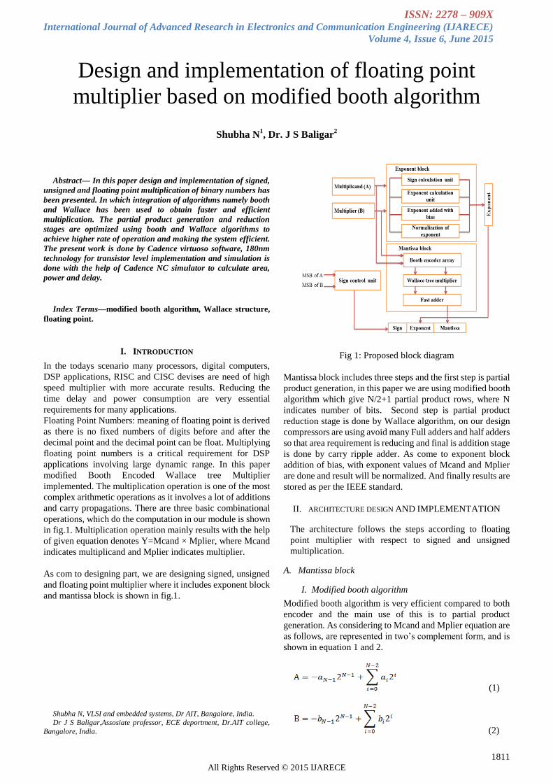
encoding values, where „X‟ is function which can be seen in
equation (3) and three bits are considered. The three bits of
functionality „X‟ is representation is shown in figure 2. In
equation x-1=0 and Mi values are {-2, -1, 0, 1, 2}. Now the
normal multiplication are explained in equation (4) and Pi is
the primary output product bit of ith
iteration and final
equation is represented in equation (5).
(3)
(4)
The equation (4), Pi denotes the primary output product bit at
ith
iteration, and this is also represented in equation (5)
X2i+
1
X2
i
X2i-
1 Fn Neg Two One zero Cor
0 0 0 +0
Y
0 0 0 1 0
0 0 1 +1
Y
0 0 1 0 0
0 1 0 +1
Y
0 0 1 0 0
0 1 1 +2
Y
0 1 0 0 0
1 0 0 -2Y 1 1 0 0 1
1 0 1 -1Y 1 0 1 0 1
1 1 0 -1Y 1 0 1 0 1
1 1 1 -0Y 1 0 0 1 0
Table2: modified booth encoded values.
(5)
Where Si written as
Si shows the three bits scanning is starts from Y-1 to the MSB
bit Y7 and three bits are select in the form of one overlapping
bit in each three bit selection and this can be seen in
representation.
Fig 2: modified booth encoder
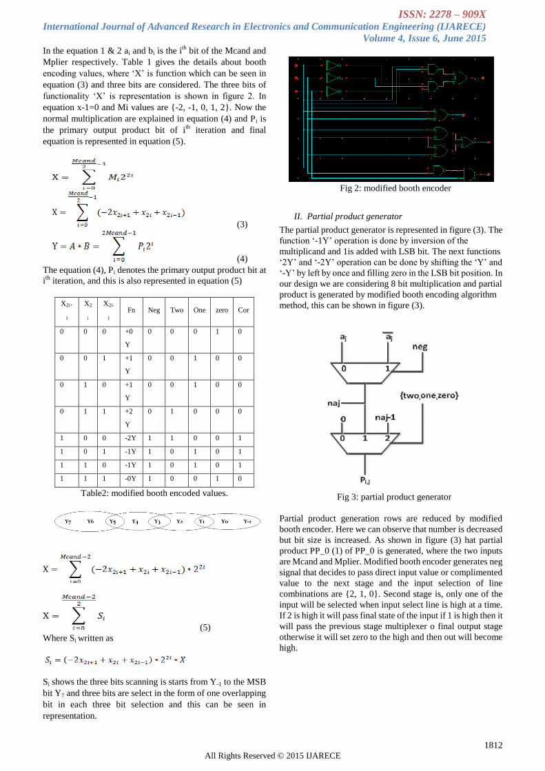
II. Partial product generator
The partial product generator is represented in figure (3). The
function „-1Y‟ operation is done by inversion of the
multiplicand and 1is added with LSB bit. The next functions
„2Y‟ and „-2Y‟ operation can be done by shifting the „Y‟ and
„-Y‟ by left by once and filling zero in the LSB bit position. In
our design we are considering 8 bit multiplication and partial
product is generated by modified booth encoding algorithm
method, this can be shown in figure (3).
Fig 3: partial product generator
Partial product generation rows are reduced by modified
booth encoder. Here we can observe that number is decreased
but bit size is increased. As shown in figure (3) hat partial
product PP_0 (1) of PP_0 is generated, where the two inputs
are Mcand and Mplier. Modified booth encoder generates neg
signal that decides to pass direct input value or complimented
value to the next stage and the input selection of line
combinations are {2, 1, 0}. Second stage is, only one of the
input will be selected when input select line is high at a time.
If 2 is high it will pass final state of the input if 1 is high then it
will pass the previous stage multiplexer o final output stage
otherwise it will set zero to the high and then out will become
high.
ISSN: 2278 – 909X International Journal of Advanced Research in Electronics and Communication Engineering (IJARECE)
Volume 4, Issue 6, June 2015
1813 All Rights Reserved © 2015 IJARECE
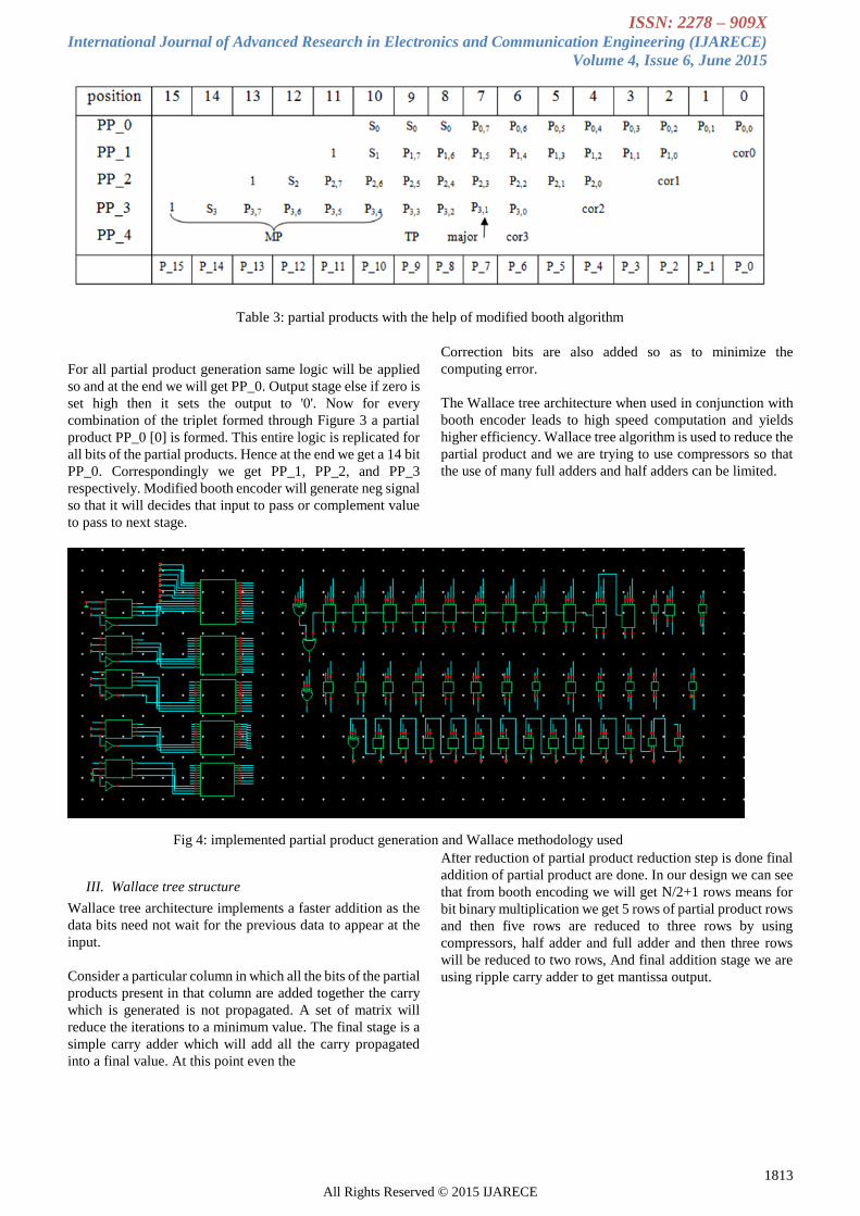
For all partial product generation same logic will be applied
so and at the end we will get PP_0. Output stage else if zero is
set high then it sets the output to '0'. Now for every
combination of the triplet formed through Figure 3 a partial
product PP_0 [0] is formed. This entire logic is replicated for
all bits of the partial products. Hence at the end we get a 14 bit
PP_0. Correspondingly we get PP_1, PP_2, and PP_3
respectively. Modified booth encoder will generate neg signal
so that it will decides that input to pass or complement value
to pass to next stage.
III. Wallace tree structure
Wallace tree architecture implements a faster addition as the
data bits need not wait for the previous data to appear at the
input.
Consider a particular column in which all the bits of the partial
products present in that column are added together the carry
which is generated is not propagated. A set of matrix will
reduce the iterations to a minimum value. The final stage is a
simple carry adder which will add all the carry propagated
into a final value. At this point even the
Correction bits are also added so as to minimize the
computing error.
The Wallace tree architecture when used in conjunction with
booth encoder leads to high speed computation and yields
higher efficiency. Wallace tree algorithm is used to reduce the
partial product and we are trying to use compressors so that
the use of many full adders and half adders can be limited.
IV. Final Addition
After reduction of partial product reduction step is done final
addition of partial product are done. In our design we can see
that from booth encoding we will get N/2+1 rows means for
bit binary multiplication we get 5 rows of partial product rows
and then five rows are reduced to three rows by using
compressors, half adder and full adder and then three rows
will be reduced to two rows, And final addition stage we are
using ripple carry adder to get mantissa output.
Fig 4: implemented partial product generation and Wallace methodology used
Table 3: partial products with the help of modified booth algorithm
ISSN: 2278 – 909X International Journal of Advanced Research in Electronics and Communication Engineering (IJARECE)
Volume 4, Issue 6, June 2015
1814 All Rights Reserved © 2015 IJARECE
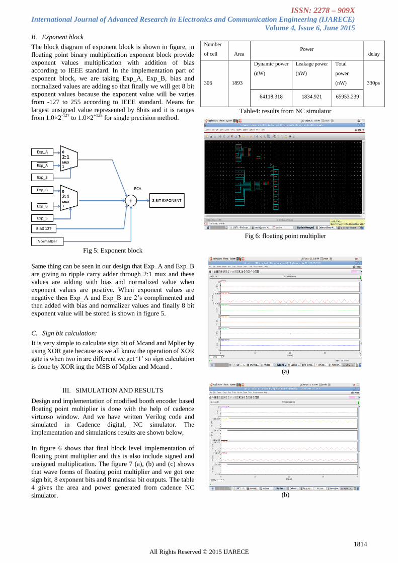
B. Exponent block
The block diagram of exponent block is shown in figure, in
floating point binary multiplication exponent block provide
exponent values multiplication with addition of bias
according to IEEE standard. In the implementation part of
exponent block, we are taking Exp_A, Exp_B, bias and
normalized values are adding so that finally we will get 8 bit
exponent values because the exponent value will be varies
from -127 to 255 according to IEEE standard. Means for
largest unsigned value represented by 8bits and it is ranges
from 1.0×2-127
to 1.0×2+128
for single precision method.
Fig 5: Exponent block
Same thing can be seen in our design that Exp_A and Exp_B
are giving to ripple carry adder through 2:1 mux and these
values are adding with bias and normalized value when
exponent values are positive. When exponent values are
negative then Exp_A and Exp_B are 2‟s complimented and
then added with bias and normalizer values and finally 8 bit
exponent value will be stored is shown in figure 5.
C. Sign bit calculation:
It is very simple to calculate sign bit of Mcand and Mplier by
using XOR gate because as we all know the operation of XOR
gate is when two in are different we get „1‟ so sign calculation
is done by XOR ing the MSB of Mplier and Mcand .
III. SIMULATION AND RESULTS
Design and implementation of modified booth encoder based
floating point multiplier is done with the help of cadence
virtuoso window. And we have written Verilog code and
simulated in Cadence digital, NC simulator. The
implementation and simulations results are shown below,
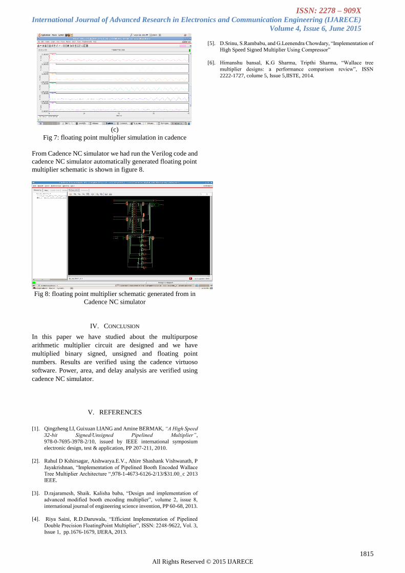
In figure 6 shows that final block level implementation of
floating point multiplier and this is also include signed and
unsigned multiplication. The figure 7 (a), (b) and (c) shows
that wave forms of floating point multiplier and we got one
sign bit, 8 exponent bits and 8 mantissa bit outputs. The table
4 gives the area and power generated from cadence NC
simulator.
Number
of cell
Area Power
delay
306
1893
Dynamic power
(nW)
Leakage power
(nW)
Total
power
(nW)
330ps
64118.318 1834.921 65953.239
Table4: results from NC simulator
Fig 6: floating point multiplier
(a)
(b)
ISSN: 2278 – 909X International Journal of Advanced Research in Electronics and Communication Engineering (IJARECE)
Volume 4, Issue 6, June 2015
1815 All Rights Reserved © 2015 IJARECE
(c)
Fig 7: floating point multiplier simulation in cadence
From Cadence NC simulator we had run the Verilog code and
cadence NC simulator automatically generated floating point
multiplier schematic is shown in figure 8.
Fig 8: floating point multiplier schematic generated from in
Cadence NC simulator
IV. CONCLUSION
In this paper we have studied about the multipurpose
arithmetic multiplier circuit are designed and we have
multiplied binary signed, unsigned and floating point
numbers. Results are verified using the cadence virtuoso
software. Power, area, and delay analysis are verified using
cadence NC simulator.
V. REFERENCES
[1]. Qingzheng LI, Guixuan LIANG and Amine BERMAK, “A High Speed
32-bit Signed/Unsigned Pipelined Multiplier”,
978-0-7695-3978-2/10, issued by IEEE international symposium
electronic design, test & application, PP 207-211, 2010.
[2]. Rahul D Kshirsagar, Aishwarya.E.V., Ahire Shashank Vishwanath, P
Jayakrishnan, “Implementation of Pipelined Booth Encoded Wallace
Tree Multiplier Architecture “,978-1-4673-6126-2/13/$31.00_c 2013
IEEE.
[3]. D.rajaramesh, Shaik. Kalisha baba, “Design and implementation of
advanced modified booth encoding multiplier”, volume 2, issue 8,
international journal of engineering science invention, PP 60-68, 2013.
[4]. Riya Saini, R.D.Daruwala, “Efficient Implementation of Pipelined
Double Precision FloatingPoint Multiplier”, ISSN: 2248-9622, Vol. 3,
Issue 1, pp.1676-1679, IJERA, 2013.
[5]. D.Srinu, S.Rambabu, and G.Leenendra Chowdary, “Implementation of
High Speed Signed Multiplier Using Compressor”
[6]. Himanshu bansal, K.G Sharma, Tripthi Sharma, “Wallace tree
multiplier designs: a performance comparison review”, ISSN
2222-1727, colume 5, Issue 5,IISTE, 2014.


![ISSN: 2278 909X International Journal of Advanced Research in …ijarece.org/wp-content/uploads/2017/05/IJARECE-VOL-6... · 2017-05-14 · McLean [3] derived relations for the minimum](https://img.pdfslide.us/doc/110x75/5ea04bb213d2e0694433d80b/issn-2278-909x-international-journal-of-advanced-research-in-2017-05-14-mclean.jpg)