Embed Size (px)
Citation preview
25
Turbulence Characteristics in a Rushton Stirring Vessel: A Numerical Investigation
Mohammad Amin Rashidifar1 and Ali Amin Rashidifar2
1Department of Mechanical Engineering, Islamic Azad University, Shadegan Branch, Shadegan, Iran2Department of Computer Science, Islamic Azad University, Shadegan Branch, Shadegan, Iran
E-mail: [email protected](Received on 15 July 2013 and accepted on 30 August 2013)
Abstract - Understanding of the flow in stirred vessels can be
useful for a wide number of industrial applications, like in
mining, chemical and pharmaceutical processes. Remodeling
and redesigning these processes may have a significant impact
on the overall design characteristics, affecting directly product
quality and maintenance costs. In most cases the flow around
the rotating impeller blades interacting with stationary baffles
can cause rapid changes of the flow characteristics, which lead
to high levels of turbulence and higher shear rates. The flow
is anisotropic and inhomogeneous over the entire volume. A
better understanding and a detailed documentation of the
turbulent flow field is needed in order to design stirred tanks
that can meet the required operation conditions. This paper
describes an effort for accurate estimation of the velocity
distribution and the turbulent characteristics (vorticity,
turbulent kinetic energy, dissipation rate) in a cylindrical vessel
agitated by a Rushton turbine (a disk with six flat blades).
Results from simulations using FLUENT (a commercial CFD
package) are compared with Time Resolved Digital Particle
Image Velocimetry (DPIV) for baseline configurations in
order to validate and verify the fidelity of the computations.
Different turbulent models are used in this study in order to
determine which one is the most appropriate. Subsequently a
parametric analysis of the flow characteristics as a function
of the clearance height of the impeller from the vessel floor
is performed. Results are presented along planes normal or
parallel to the impeller axis, displaying velocity vector fields
and contour plots of vorticity turbulent dissipation and others.
Special attention is focused in the neighborhood of the impeller
region and the radial jet generated there. The present results
provide useful information for the design of the mixing process
as well as for more accurate estimations in future work.
Asian Journal of Science and Applied TechnologyISSN: 2249 - 0698 Vol. 2 No. 2, 2013, pp. 25 - 42
© The Research Publication, www.trp.org.in
nomEnclaturE
Keywords: Mixing; Stirring tank; Turbulence; DPIV;
FLUENT; Rushton turbine
AJSAT Vol.2 No.2 July - December 2013

26
I. IntroductIon
In many industrial and biotechnological processes, mixing is achieved by rotating an impeller in a vessel containing a fluid (stirred tank). The vessel is usually a cylindrical tank equipped with an axial or radial impeller. In most cases, baffles are mounted on the tank wall along the periphery. Their purpose is to prevent the flow from performing a solid body rotation (destroy the circular flow pattern) [1], to inhibit the free surface vortex formation which is present in unbaffled tanks [2] and to improve mixing. However, their presence makes the simulations more difficult and demanding as they remain stationary while the impeller rotates.
There are two types of mixing, laminar and turbulent. Although laminar mixing has its difficulties and has been studied in the past [1] by many authors, in most industrial applications where large scale stirring vessels are used turbulence is predominant. Turbulent flows are far more complicated and a challenging task to predict due to their chaotic nature [4], [5]. In the case of stirred tanks, not only the flow is fully turbulent, but it is also strongly inhomogeneous and anisotropic due to the energetic agitation induced by the impeller. In addition, the flow is periodic, because of the interaction between the blades and the baffles. This leads to periodic velocity fluctuations, which are often referred to as pseudo-turbulence [6]. Energy is transported from the large to the small eddies and then dissipated into the smallest ones according to the Kolmogorov’s energy cascade. The size of these smallest eddies can be calculated from the following equation:
34ReIDη −= (1)
However in mixing tanks we have additional energy coming from the rotation of the impeller that is smaller from the one coming from the large eddies but bigger from the one that is dissipated into the smallest scales. Thus this energy is located in the middle of the energy spectrum [7]. There are many parameters such as the type and size of the impeller, its location in the tank (clearance), and the presence of baffles that affect the nature of the generated flow field. All these geometrical parameters and many others (e.g. rotational speed of the impeller) make the optimum design of a mixing tank a difficult and time consuming task [8].
Accurate estimation of the dissipation rate ( ε )distribution and its maximum value in stirred tanks end especially in the vicinity of the impeller is of great importance. This is because of a plethora of industrial processes such as particle, bubble breakup, coalescence of drops in liquid-liquid dispersions and agglomeration in crystallizers require calculation of the eddy sizes which are related directly to the turbulent kinetic energy and the dissipation rate [1], [9], [10].
In the last two decades significant experimental work has been published contributing to the better understanding of the flow field and the shedding light to the complex phenomena that are present in stirred tanks. In most of these studies accurate estimation of the turbulent characteristics and the dissipation rate were the other important aspects [2], [4], [8].
There is a wealth of numerical simulations of mixing vessels. In most of these studies the Rushton turbine [10], [11], [12], [13], [14], [15] was used while in others, the pitched blade impeller (the blades have an angle of 45 degrees) [9] or combination of above two [8], [15] was considered. Only a few were carried out using Large Eddy Simulations (LES) in unbaffled [2] and baffled stirred tanks [1], [5], [16]. A variety of different elevations of the impellers and Reynolds numbers were considered.
Today, continuing increase of computer power, advances in numerical algorithms and development of commercial Computational Fluid Dynamics (CFD) packages create a great potential for more accurate and efficient three dimensional simulations.
In this study we employ a CFD code to analyze the flow in a baffled tank agitated by a Rushton impeller. The selection of the impeller and the mixing tank geometrical parameters were made to facilitate comparisons with available experimental data. The primary objective of this study is to produce numerically a complete parametric study of the time-averaged results based on the Reynolds number, the turbulent models and the clearance of the impeller. The CFD results are compared with those obtained by the present team via a Digital Particle Image Velocimetry. These data were generated with sufficient temporal resolution capable to resolve the global evolution of the flow. The commercial
AJSAT Vol.2 No.2 July - December 2013
Mohammad Amin Rashidifar and Ali Amin Rashidifar

27
package FLUENT [17] was used for the simulation and the package GAMBIT [18] as a grid generator. MIXSIM [19] is another commercial package specialized in mixing having a library with a variety of industrial impellers.
A number of different turbulent models is available in FLUENT as in most of the CFD commercial packages. The choice of an appropriate turbulent model is of great significance for getting an accurate solution. In this work we used mostly the two-equation models called k-ε. These models have been extensively tested in many applications. These models are based on the assumption of the homogenous isentropic turbulent viscosity, which is not strictly consistent with our case. And yet they predict quite well the velocity distribution and the dissipation rate. We also used the RSM model. Although this model is more
1c) The working fluid was water and its height was equal to the height of the tank. This model is identical to the model employed in the experimental work carried out by the present team.
III. goVErnIng EquatIons
The continuity equation and the momentum equations for three dimensional incompressible unsteady flows are given as follows [20], [21], [22]:
general than the two-equation models, it is computationally time consuming because it consists of seven equations for the turbulence modeling, allowing the development of anisotropy, or re-orientation of the eddies in the flow. It should therefore provide good accuracy in predicting flows with swirl, rotation and high strain rates.
II. mIxIng tank modEl
Three dimensional simulations were carried out in a baffled cylindrical vessel with diameter TD (Figure 1a). Four equally spaced baffles with width 0.1bf Tw D= and thickness / 40bf Ith D= were mounted on the tank wall. The tank was agitated by a Rushton turbine (disk with six perpendicular blades) with diameter / 3I TD D= , disk diameter 0.75D ID D= , blade width / 4bl Iw D= , blade height 0.2bl Ih D= blade thickness 0.01bl Ith D= . (Figure 1b,
Fig. 1 Rushton Tank and Impeller Configuration
a.
b.
c.
(2)
(3)
Although body forces include gravitational, buoyancy, porous media and other user defined forces in our case includes only the gravitational force. In the case of the steady state simulations the first term on the left hand side in both the continuity and the momentum equation is zero.
AJSAT Vol.2 No.2 July - December 2013
Turbulence Characteristics in a Rushton Stirring Vessel: A Numerical Investigation

28
Velocity (u) and pressure (p) can be decomposed into the sum of their mean ( , u p ) and the fluctuation components ( ' ', pu ):
(4)
Noting the rules for averaging:
(5)
The above two rules state that the average of the average velocity is equal again to the average and that the average of the fluctuating component is equal to zero.
By applying (4) and (5) into (1) and (2) in which already we had get rid of the first terms we obtain the time–averaged governing equations:
(6)
(7)
The last term is the divergence of the Reynolds stress tensor. It comes from the convective derivative. So strictly, the Reynolds stresses are not stresses; they are the averaged effect of turbulence convection.
Modeling is usually achieved using the Boussinesq’s hypothesis. In this case the turbulent viscosity depends only the turbulent structure and not on the fluid properties [16].
(8)
IV. mIxIng tank sImulatIons
Three-dimensional simulations were carried out in three sets of calculations, using three different clearance heights of the impeller. In the first the clearance was set to / 1/ 2TC D = (impeller in the middle of the tank) and five Reynolds numbers (Re) in the range 20000 to 45000 were chosen. For every Re number three turbulent models, namely Standard k ε− , RNG k ε− and Reynolds Stresses were tested in order to investigate their predictive accuracy in this kind of flow. In the second set of calculations the clearance of the impeller was set to / 1/15TC D =(impeller almost at the bottom of the tank) and simulations
were performed again but this time using only the one of the above three turbulent models that had overall the best performance. In the last configuration the proximity to the ground was set to C/T=1/3 and two turbulent models were tested, the Standard K-e and the Reynolds Stresses. The latter had been chosen due to the availability of experimental data from the literature about the Reynolds stresses. More information about the test cases is listed in Table I. In all sets of calculations, the origin of the coordinate system was fixed in the center of the impeller. The Reynolds number was based on the impeller diameter, Re=NDI
2/ν.
The domain of integration was meshed with the aid of the commercial grid generator package GAMBIT creating a hybrid three dimensional grid. The hybrid grid is actually an unstructured grid that contains different types of elements. In our study 480.000 quadrilaterals and triangle elements were used to construct the mesh. The choice of having an unstructured grid versus a structured one was made due to the fact that in a complex flow like the present, details of the flow field everywhere in the tank and especially in the discharge area of the impeller and behind the baffles must be captured. Then the model was launched to FLUENT for the simulation part. Although FLUENT does not use a cylindrical coordinate system, all the notation in this study was converted to cylindrical making the following changes in notation: , y= and z zx r ϕ= ≡
The simulations were accomplished using the steady-state Multi Reference Frame (MRF) approach that is available in FLUENT. In this approach the grid is divided in two or more reference frames to account for the stationary and the rotating parts. In the present case the mesh consists of two frames, one for the tank away from the impeller and one including the impeller. The latter rotates with the rotational speed of the impeller but the impeller itself remains stationary. The unsteady continuity and the momentum equations are solved inside the rotating frame while in the outside stationary frame the same equations are solved in a steady form. At the interface between the two frames a steady transfer of information is made by FLUENT. One drawback of the MRF approach is that the interaction between the impeller and the baffles is weak.
AJSAT Vol.2 No.2 July - December 2013
Mohammad Amin Rashidifar and Ali Amin Rashidifar

29
V. rEsults and dIscussIon
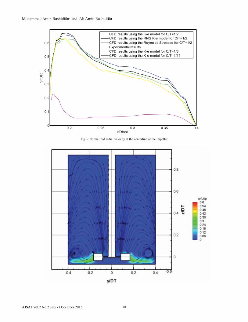
Figure 2 shows the distribution of the radial velocity across the centerline of the impeller for all the turbulent models and configurations tested. We observe that all the models predict quite well the radial velocity. This plot can also verify the low speed radial jet produced by the impeller for low clearance configuration (C/T=1/15). Figure 3 shows the contour plots of the spatial distribution of the radial velocity superimposed with streamlines in the baffle plane ( / 0Tr D = ) for the three configurations. In the case of the low clearance, only one large recirculation area on each side of the tank is observed, while in the other cases, two distinct toroidal zones above and below the impeller divide the flow field in two parts (in half for the case of C/T=1/2 and in one third in the case of C/T=1/3). According to [1] these large-scale ring vortices [21] act as a barrier to mixing by increasing the blend time. It can also be noticed that in the latter cases the radial jet is more energetic than it is in the first. Figure 4 presents the contours of the dissipation rate in the impeller e plane ( / 0Tr D = ) for both configurations. The maximum dissipation was calculated in a rectangular region along the tip of the blade. Although in this study we present the maximum dissipation found in this “box”, the result is very sensitive to its definition, especially as we go closer to the blade, because the value of the maximum dissipation changes drastically. Despite the fact that the RNG k-e model gave poor results for the radial velocity in the centerline of the impeller, it had superior behavior among the studied turbulent models in predicting the Turbulent Dissipation Rate (TDR) as illustrated in Figure 5. A parametric study for all the turbulent models, elevations and Re numbers for the maximum dissipation is presented in Figure 6. As the Re number increases the maximum TDR for the / 1/ 2TC D = configuration decreases. This is in agreement with our experimental data and those of
Table I SIMulaTIon TeST MaTrIx
Baldi’s et Al [24]. Unfortunately, no experimental data are available for the configuration where the impeller is almost at the bottom of the Tank. For this case the line of the maximum dissipation levels off. Figure 7 demonstrates the normalized Turbulent Kinetic Energy (TKE) in a plane that passes through the middle plane of the impeller ( / 0Tz D = ) [15]. It can be observed that the TKE has smaller values in the case of the low configuration. In Figure 8 a difference between the experimental and the computational results can be observed. This apparent discrepancy is due to the periodicity that characterizes the flow, since with every passage of a blade strong radial jet is created. By removing (filtering) this periodicity matching of the experimental and the computational results can be achieved Figure 9 shows the Zvorticity in the middle plane of the impeller ( / 0Tz D = ). For both configurations, vortices behind the baffles are formed [24]. For the cases of clearance / 1/ 2TC D = trailing vortices that form behind the impeller blades can also be observed. Figure 10 demonstrates the nondomensionalized Xvorticity in the baffle plane ( / 0Tr D = ) in which the trailing vortices from the rotating blades can be seen. For the low clearance case only one large ring vortex forms.
VI. conclusIons
The present calculations indicate that turbulent kinetic energy and dissipation are largest in the immediate neighborhood of the impeller. However, the contours that describe the levels of these quantities are not symmetric about the plane of the impeller in the case of low clearance with the bottom. There is a strong tendency to skew these contours downward. This behavior can be explained by observing the streamline configurations. Apparently, the dominant downward flow is diverting the jet-like flow that leaves the tip of the impeller downward, and it convects with it the turbulent features of the flow.
AJSAT Vol.2 No.2 July - December 2013
Turbulence Characteristics in a Rushton Stirring Vessel: A Numerical Investigation
30
Fig. 2 Normalized radial velocity at the centerline of the impeller
0.2 0.25 0.3 0.35 0.40
0.1
0.2
0.3
0.4
0.5
0.6
r/Dtank
Vr/U
tip
CFD results using the K-e model for C/T=1/2CFD results using the RNG K-e model for C/T=1/2CFD results using the Reynolds Stresses for C/T=1/2Experimental resultsCFD results using the K-e model for C/T=1/3CFD results using the K-e model for C/T=1/15
AJSAT Vol.2 No.2 July - December 2013
Mohammad Amin Rashidifar and Ali Amin Rashidifar

31
Fig. 3 Normalized radial velocity for Re=35000 at / 0Tr D = for / 1/15TC D = (top frame), for / 1/ 2TC D = (middle frame) and for / 1/ 3TC D = (bottom frame)
AJSAT Vol.2 No.2 July - December 2013
Turbulence Characteristics in a Rushton Stirring Vessel: A Numerical Investigation

32AJSAT Vol.2 No.2 July - December 2013
Mohammad Amin Rashidifar and Ali Amin Rashidifar

33
Fig. 4 Normalized Dissipation rate for Re=35000 at / 0Tr D = for / 1/15TC D = (top frame), for / 1/ 2TC D = (middle frame) and / 1/ 3TC D = (bottom frame)
Fig. 5 Normalized Dissipation rate at the centerline of the impeller
0.2 0.25 0.3 0.35 0.4
5
10
15
20
25
30
r/Dtank
ε/(N
3 Dim
p2 )
CFD results using the K-e model for C/T=1/2CFD results using the RNG K-e model for C/T=1/2CFD results using the Reynolds Stresses for C/T=1/2Experimental resultsCFD results using the K-e model for C/T=1/3CFD results using the K-e model for C/T=1/15
AJSAT Vol.2 No.2 July - December 2013
Turbulence Characteristics in a Rushton Stirring Vessel: A Numerical Investigation

34
Fig. 6 Normalized maximum dissipation rate versus the Re number for / 1/15TC D = (top frame), for / 1/ 2TC D = (middle frame) and for / 1/ 3TC D = (bottom frame)
AJSAT Vol.2 No.2 July - December 2013
Mohammad Amin Rashidifar and Ali Amin Rashidifar

35 AJSAT Vol.2 No.2 July - December 2013
Turbulence Characteristics in a Rushton Stirring Vessel: A Numerical Investigation

36
Fig. 7 Normalized Turbulent Kinetic Energy for Re=35000 at / 0Tz D = for / 1/15TC D = (top frame), for / 1/ 2TC D = (middle frame) and for
/ 1/ 3TC D = (bottom frame)
Fig. 8 Normalized TKE at the centerline of the impeller with and without periodicity for Re=35000
AJSAT Vol.2 No.2 July - December 2013
Mohammad Amin Rashidifar and Ali Amin Rashidifar

37 AJSAT Vol.2 No.2 July - December 2013
Turbulence Characteristics in a Rushton Stirring Vessel: A Numerical Investigation

38
Fig. 9 Normalized Z vorticity for Re=35000 at / 0Tz D = for / 1/15TC D = (top frame), for / 1/ 2TC D =(middle frame) and for / 1/ 3TC D = (bottom frame)
AJSAT Vol.2 No.2 July - December 2013
Mohammad Amin Rashidifar and Ali Amin Rashidifar

39
Fig. 10 Normalized Xvorticity for Re=35000 at / 0Tr D = for / 1/15TC D = (top frame), for / 1/ 2TC D =(middle frame) and for / 1/ 3TC D = (bottom frame)
AJSAT Vol.2 No.2 July - December 2013
Turbulence Characteristics in a Rushton Stirring Vessel: A Numerical Investigation

40
Fig.11 Normalized radial velocity profiles at r/T=0.256 (top frame) and at r/T=0.315 (bottom frame) for / 1/ 2TC D = and Re=35000
AJSAT Vol.2 No.2 July - December 2013
Mohammad Amin Rashidifar and Ali Amin Rashidifar

41
Fig. 12 Normalized Dissipation rate profiles at r/T=0.256 (top frame) and at r/T=0.315 (bottom frame) for / 1/ 2TC D = and Re=35000
AJSAT Vol.2 No.2 July - December 2013
Turbulence Characteristics in a Rushton Stirring Vessel: A Numerical Investigation

42
rEfErEncEs
[1] Derksen, J., and Van den Akker, H. E. A., 1999, “Large Eddy Simulations on the Flow Driven by a Rushton turbine”, A.I.Ch.E. Journal., 45, (2), pp. 209-222
[2] Alcamo, R., Micale, G., Grisafi, F., Brucato, A., and Ciofalo, M., “Large-eddy simulation of turbulent flow in an unbaffled stirred tank driven by a Rushton turbine”, 2005, Chem. Eng. Sci., 60, pp. 2303-2316
[3] Lamberto, D. J., Muzzio, F. J., Swanson, P. D., and Tonkovich, A. L., 1996 “Using Time-Dependent RPM to Enhance Mixing in Stirred Vessels”, Chem. Eng. Sci., 51, pp. 733-741.
[4] Bakker, A., and Van den Akker, H. E. A., 1994 “Single-phase flow in stirred reactors”, Trans. I.Chem.E., 72, pp. 583-593
[5] Yeho, S. L., Papadakis, G., and Yianneskis, M., “Numerical Simulation of Turbulent Flow Characteristics in a Stirred Vessel Using the LES and RANS Approaches with the Sliding/Deforming Mesh Methodology”, 2004, Trans I.Chem.E., Part A, Chem. Eng. Res. Des., 82, (A7), pp. 834-848
[6] Van’t Riet, K., Bruijin, W., and Smith, J. M., 1976, “Real and Pseudo Turbulence in the Discharge Stream from a Rushton Turbine”, Chem. Eng. Sci., 31, pp. 407-412
[7] Sharp, K. V., and Adrian, R. J., “PIV Study of Small Scale Flow Structure around a Rushton Turbine”, 2001, A.I.Ch.E. Journal., 47, (4), pp. 766-778
[8] Zhou, G., and Kresta, S. M., 1996, “Impact of Tank Geometry on the Maximum Dissipation rate for Impellers”, A.I.Ch.E. Journal., 42, (9), pp. 2476-2490
[9] Bhattacharya, S., and Kresta, S. M., 2002, “CFD Simulations of Three Dimensional Wall Jets in a Stirred Tank”, Can. J. Chem. Eng., 80, pp. 1-15
[10] Kresta, S. M., and Wood, P. E., 1991, “Prediction of the Three-Dimensional Turbulent Flow in Stirred Tanks”, A.I.Ch.E. Journal., 37 (3), pp. 448-460
[11] Jenne, M., and Reuss, M., 1999, “A critical assessment on the use of k-ε turbulence models for simulation of the turbulent liquid flow induced by a Rushton-turbine in baffled stirred-tank reactors”, Chem. Eng. Sci., 54, pp. 3921-3941
[12] Micheletti, M., Baldi, S., Yeoh, S. L., Ducci, A., Papadakis, G., Lee, K. C., and Yianneskis, M., 2004, “On Spatial and Temporal Variations and Estimates of Energy Dissipation”, Trans I. Chem.E., Part A, Chem. Eng. Res. Des., 82, (A9), pp. 1188-1198
[13] Ranade, V. V., “An Efficient Computational Model for Simulating Flow in Stirred Vessels: A Case of Rushton Turbine”, 1997, Chem. Eng. Sci., 52, (24), pp. 4473-4484
[14] Ranade, V. V., Perrard, M., Le Sauze, N., Xuereb, C., and Bertrand, J., 2001, “Trailing Vortices of Rushton Turbine: PIV Measurements and CFD Simulations with Snapshot Approach“, Chem. Eng. Res. Des., 79, (A), pp. 3-12
[15] Ranade, V. V., 2002, “CFD Predictions of Flow near Impeller Blades in Baffled Stirred Vessels: Assessment of Computational Snapshot Approach”, Chem. Eng. Comm., 189, pp. 895-922
[16] Bakker, A., and Oshinowo, L. M., 2004, “Modeling of Turbulence in Stirred Vessels using Large Eddy Simulations”, Chem. Eng. Res. Des., 82, (A9) pp. 1169-1178
[17] FLUENT Inc. FLUENT 6 Users Guide, published by FLUENT Inc., Lebanon, New Hampshire, USA, 2005.
[18] FLUENT Inc. GAMBIT Users Guide, published by FLUENT Inc., Lebanon, New Hampshire, USA, 2004.
[19] FLUENT Inc. MIXSIM Users Guide, published by FLUENT Inc., Lebanon, New Hampshire, USA, 2003
[20] Durbin, P. A., and Petterson Reif, B.A., 2001, “Statistical Theory and Modeling for Turbulent Flows”, John Wiley & Sons, LTD, Chapter
[21] Paul, E. L., Atiemo-Obeng, V. A., and Kresta, S. M., “Handbook of Industrial Mixing: Science and Practice”, 2004, John Wiley & Sons, Wiley Interscience, Chapter 5
[22] Pope, S. B., “Turbulent Flows”, 2000, Cambridge University Press, Cambridge, UK, Chapter
[23] Ranade, V. V., “Computational Flow Modeling for Chemical Reactor Engineering”, 2002, Process System Engineering Volume 5, Academic Press
[24] Baldi, S., and Yianneskis, M., “On the Quantification of Energy Dissipation in the Impeller Stream of a Stirred Vessel from Fluctuating Velocity Gradient Measurements”, Chem. Eng. Sci., 59, pp. 2659-2671
[25] Jones, W.P., and Launder, B.E., “The prediction of laminarization with a two-equation model”, Int. J. Heat Mass Transfer, 15, pp.304-314
[26] Schubert, H., 1999, “On the turbulence-controlled microprocesses in flotation machines”, Int. J. Miner. Process., 56, pp. 257-276
[27] Fallenius, K., 1987, “Turbulence in Flotation Cells”, Int. J. Miner. Process., 21, pp. 1-23
[28] Do, H., and Yoon, R.H., “A flotation model under turbulent flow conditions”.
AJSAT Vol.2 No.2 July - December 2013
Mohammad Amin Rashidifar and Ali Amin Rashidifar


![OPEN ACCESS Journal ISSN: 2249-6645NC- DATES2K16] - 2016/MECH... · OPEN ACCESS Journal ISSN: 2249-6645 Of Modern Engineering Research (IJMER) CMR ENGINEERING COLLEGE, Kandlakoya](https://img.pdfslide.us/doc/110x75/5a71348d7f8b9a98538cb09c/open-access-journal-issn-2249-6645wwwijmercompapersnc-dates2k16-2016mechpdf.jpg)


![ISSN: 2249 - 0698 Vol. 2 No. 2, 2013, pp. 25 - 42 © …...Although laminar mixing has its difficulties and has been studied in the past [1] by many authors, in most industrial applications](https://img.pdfslide.us/doc/110x75/5e7caa78ca603f14ca4c5787/issn-2249-0698-vol-2-no-2-2013-pp-25-42-although-laminar-mixing.jpg)