Embed Size (px)
Citation preview

Journal of Theoretical and Applied Information Technology 20
th December 2014. Vol.70 No.2
© 2005 - 2014 JATIT & LLS. All rights reserved.
ISSN: 1992-8645 www.jatit.org E-ISSN: 1817-3195
333
A REVIEW ON LASER SPOT DETECTION SYSTEM BASED
ON IMAGE PROCESSING TECHNIQUES
1NOR FARIZAN ZAKARIA,
2MOHD ASYRAF ZULKIFLEY,
3MOHD. MARZUKI MUSTAFA,
4ROHANA ABDUL KARIM
Department of Electrical, Electronic & Systems Engineering, Faculty of Engineering & Built Environment
Universiti Kebangsaan Malaysia, Bangi, MALAYSIA
E-mail: [email protected], [email protected], [email protected], [email protected]
ABSTRACT
Laser pointer is a low-cost daily essential item that can provide a prominent spot, deliver the meaning of a pointing gesture and accurately indicate a spot. Robust detection of a laser spot has been made possible with the help of the computer vision techniques. Autonomous laser spot detection system has led to the evolution of many applications such as laser pointer interaction, autonomous robotic helper and simulation based computer game. This paper aims to provide the general architecture and methodology used in a laser spot detection system. Major lower level processing methods, such as thresholding, background subtraction, region of interest extraction and coordinate mapping are fundamental in developing a good laser spot system. Our study found out that most of existing systems are prone to error whenever the lighting condition is varied either gradually or suddenly. The spot is also difficult to detect when it is overlaid on a white background due to the weakness in the detection scheme. Jitter, which is mostly caused by uneven hand movement, is a big challenge in developing an accurate system, especially for laser interaction applications. Finally, we believe that a robust laser spot detection system can be built if the aforementioned challenges are carefully addressed.
Keywords: Laser Spot Detection, Coordinate Mapping, ROI Extraction, Thresholding, Background
Subtraction 1. INTRODUCTION
Laser based pointing system has been used
successfully in many applications such as tele-medicine [1-3], tele-tutoring [4-6], tele-surgery [7-9] and tele-conference [10]. With the advent of parallel processor, especially graphical processing unit (GPU), many tele-pointing systems are developed for real-time usage, in which the laser is detected and tracked autonomously. Previously, laser spot in tele-tutoring system was detected manually by the observers without any assistance from an automated detection system. The main weakness of this approach is the observers might fail to detect the spot in some challenging circumstances such as lighting changes, difference in viewing angle and shadow. In order to enhance the system, image processing techniques have been used to help the users to detect and track the laser spot autonomously. This support system has accelerated the development of many applications that dependent on autonomous detection, e.g. optical distance measurement device [11-13],
autonomous robot helpers [14-19] and shooting range training simulator [20-23].
Generally, a laser spot is defined as a small illuminated area on a surface that originated from a laser pointer. Usually, laser pointer is a pen shaped device composed of a laser diode that produces a visible spot when the incident light hit an opaque surface. The typical size of a laser spot is less than 1 cm radius. A laser spot cannot be observed when the pointer is pointed to the sky because of the non-opaqueness property of the space and light diffusion. However, high-powered laser pointer has been used in the astronomy field for outer space investigation purpose, in which a visible beam will look like an elongated pointing stick. Most of the laser pointer devices are battery operated and the allowable power is restricted to 5mW in many countries due to potential danger to human eye.
In 1980s, laser pointer was a very expensive device, but the manufacturing cost has reduced significantly since then due to high

Journal of Theoretical and Applied Information Technology 20
th December 2014. Vol.70 No.2
© 2005 - 2014 JATIT & LLS. All rights reserved.
ISSN: 1992-8645 www.jatit.org E-ISSN: 1817-3195
334
demand. Modern fabrication method has also reduced the size and weight of a laser pointer, making it possible to be used in normal household applications. Nowadays, the price is considered cheap and it has become a popular souvenir in the form of key chain.
The emitted laser from a tele-pointer can be found in many colours, dependent on the wavelength used. Visible colour laser pointer has a wavelength ranging from 400nm to 700nm, which usually emit red, green or yellow colour. Laser that operates outside of these ranges would be invisible to human eye and it often known as UV or IR laser. Usually, red laser pointer is produced by using a 650nm diode, red-orange laser pointer is emitted by a 635nm diode and green pointer is produced by a 532nm diode. Orange and green laser pointers are more expensive but works the best for human as our eyes are more sensitive to it. Green laser pointers are 50 times brighter than the red laser pointers of the same power. It is also a favourite colour used in star gazing activity since the green beam can be projected clearly during the night.
The most popular usage of a laser pointer is to aid the presenter in conveying the meaning by adding basic localization and gesture information. If a presenter points out his finger directly to a large screen and state that, “this object on the upper left corner of the slide” during a presentation, the audience may not get the specific location of the information. However, the audience can be directed to a specific location on the slide by using the laser pointer. It also allows the presenter to move freely as he can point precisely even from a distance. With the advancement of autonomous detection system, current laser based pointing system allows the user to interact directly with the projection screen. The presenter can change slides, move or delete objects even from the back of the presentation room. Modern laser pointer also can react and imitate the functions of a mouse and it can become an input device to the computer.
Since then, laser pointer has been applied beyond the normal classroom applications. Besides, laser pointer can precisely point to an object at a long distance, which allows the elderly or disabled person to point to an object so that a robot can be instructed remotely in a smart home system. These will reduce the mobility needs of the disabled person such as to reach the telephone in emergency case or to retrieve a displaced remote control. The light weight property of the device will also make it user friendly to the elderly.
Besides than giving a reliable pointing direction, it can also produce a prominent spot even in a very bright surrounding. This allows it to function as a sensor to any application that requires an indicator in a bright environment. By using this property, the military has used laser pointer to mark targets for laser-guided weaponry such as the 'Paveway' bomb and the 'JDAMS' (joint direct attack munitions) bomb [24]. This enables them to pin point the targets clearly even in a noisy environment.
The main objective of this study is to give an overview of the architecture and the current existing methods used in a laser spot detection system. The major focus will be on the lower level processing methods, such as thresholding, background subtraction, region of interest extraction and coordinate mapping which are fundamental in developing a good laser spot detection system. Apart from that, we have also discussed the various type of available laser pointer interactions, particularly with large screen and external appliances.
This paper is arranged into four main sections. Section 2 introduces the architecture of a typical laser spot detection system. Section 3 discusses the algorithm flow of the system that focuses on methods used in detecting a laser spot, mapping the coordinates from a camera to a display, and classifying the actions that can be interpreted from a laser spot movement. Finally, section 4 concludes the whole paper and some possible future directions are discussed.
2. BASIC ARCHITECTURE OF LASER
SPOT DETECTION SYSTEM
The laser spot detection system is meant to
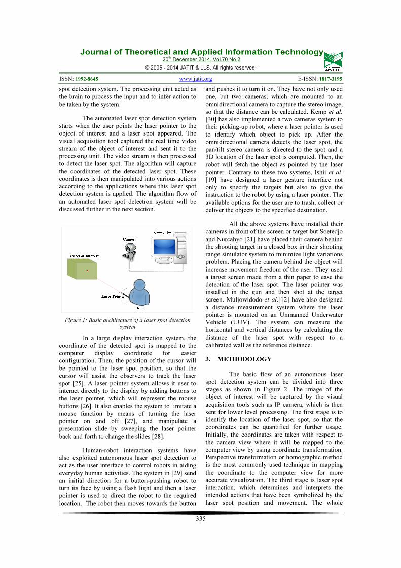
segment the laser spot automatically from the background by using a computer vision approach. The basic architecture of an automated laser spot detection system is shown in figure 1. It consists of a laser based pointing device such as a laser pointer, an object of interest, a visual acquisition tool such as video camera or webcam and a processing unit such as personal computer or microcontroller. The object of interest differs depending on the application where this system is applied. It may be a projection screen in a smart classroom system, a household object such as remote control in a smart home system or a wall in a distance measuring system. The visual acquisition tool acted as the eye of the computer vision system and provides the real-time visual input for the laser
Journal of Theoretical and Applied Information Technology 20
th December 2014. Vol.70 No.2
© 2005 - 2014 JATIT & LLS. All rights reserved.
ISSN: 1992-8645 www.jatit.org E-ISSN: 1817-3195
335
spot detection system. The processing unit acted as the brain to process the input and to infer action to be taken by the system.
The automated laser spot detection system starts when the user points the laser pointer to the object of interest and a laser spot appeared. The visual acquisition tool captured the real time video stream of the object of interest and sent it to the processing unit. The video stream is then processed to detect the laser spot. The algorithm will capture the coordinates of the detected laser spot. These coordinates is then manipulated into various actions according to the applications where this laser spot detection system is applied. The algorithm flow of an automated laser spot detection system will be discussed further in the next section.
Figure 1: Basic architecture of a laser spot detection
system
In a large display interaction system, the coordinate of the detected spot is mapped to the computer display coordinate for easier configuration. Then, the position of the cursor will be pointed to the laser spot position, so that the cursor will assist the observers to track the laser spot [25]. A laser pointer system allows it user to interact directly to the display by adding buttons to the laser pointer, which will represent the mouse buttons [26]. It also enables the system to imitate a mouse function by means of turning the laser pointer on and off [27], and manipulate a presentation slide by sweeping the laser pointer back and forth to change the slides [28].
Human-robot interaction systems have also exploited autonomous laser spot detection to act as the user interface to control robots in aiding everyday human activities. The system in [29] send an initial direction for a button-pushing robot to turn its face by using a flash light and then a laser pointer is used to direct the robot to the required location. The robot then moves towards the button
and pushes it to turn it on. They have not only used one, but two cameras, which are mounted to an omnidirectional camera to capture the stereo image, so that the distance can be calculated. Kemp et al. [30] has also implemented a two cameras system to their picking-up robot, where a laser pointer is used to identify which object to pick up. After the omnidirectional camera detects the laser spot, the pan/tilt stereo camera is directed to the spot and a 3D location of the laser spot is computed. Then, the robot will fetch the object as pointed by the laser pointer. Contrary to these two systems, Ishii et al. [19] have designed a laser gesture interface not only to specify the targets but also to give the instruction to the robot by using a laser pointer. The available options for the user are to trash, collect or deliver the objects to the specified destination.
All the above systems have installed their cameras in front of the screen or target but Soetedjo and Nurcahyo [21] have placed their camera behind the shooting target in a closed box in their shooting range simulator system to minimize light variations problem. Placing the camera behind the object will increase movement freedom of the user. They used a target screen made from a thin paper to ease the detection of the laser spot. The laser pointer was installed in the gun and then shot at the target screen. Muljowidodo et al.[12] have also designed a distance measurement system where the laser pointer is mounted on an Unmanned Underwater Vehicle (UUV). The system can measure the horizontal and vertical distances by calculating the distance of the laser spot with respect to a calibrated wall as the reference distance.
3. METHODOLOGY
The basic flow of an autonomous laser
spot detection system can be divided into three stages as shown in Figure 2. The image of the object of interest will be captured by the visual acquisition tools such as IP camera, which is then sent for lower level processing. The first stage is to identify the location of the laser spot, so that the coordinates can be quantified for further usage. Initially, the coordinates are taken with respect to the camera view where it will be mapped to the computer view by using coordinate transformation. Perspective transformation or homographic method is the most commonly used technique in mapping the coordinate to the computer view for more accurate visualization. The third stage is laser spot interaction, which determines and interprets the intended actions that have been symbolized by the laser spot position and movement. The whole

Journal of Theoretical and Applied Information Technology 20
th December 2014. Vol.70 No.2
© 2005 - 2014 JATIT & LLS. All rights reserved.
ISSN: 1992-8645 www.jatit.org E-ISSN: 1817-3195
336
process of detecting the laser spot will be iterated again for the next frame and it will be the input for higher level processing. Most of the existing applications follow these procedures, yet some applications may have added an additional calibration stage, which was done during the start up.
Figure 2: Flowchart of an autonomous laser spot
detection system.
3.1 System Calibration
System calibration was performed by adjusting the setting of the camera so that most of the unwanted image noise will be removed during the early stage. Brightness is one of the major parameters in calibration that controls the allowable light onto the image sensors in the camera. This exposure is controlled by adjusting the shutter, ISO and aperture setting. Another parameter is white balance setting, which will adjust the colour in an image to appear accurately, so that white colour will appear as white in the captured image. Most of the modern cameras came with an automated setting for white balance and exposure control to ease the shooting process.
However, automatic control in camera may cause problems in image processing as it leads to unpredictable change in the parameters. The reason is the algorithm for automated adjustment can only work in certain environments. To avoid such complications, all of these controls were turned off. Then, the settings were physically set by using a trial and error method. Some researchers [31-33] have tuned the brightness and exposure
level manually until the laser spot can be detected as a large white spot on the screen. However, lighting condition can be too bright that it pushes each pixel in the image to reach the saturated level. Ahlborn et al. [32] minimised the problem by applying the possible shortest shutter time to limit the overexposed image problem. Besides, a few papers [34-36] have set a predetermined value for their camera setting to minimize over exposure. Fukuchi [34] has set the exposure setting to 1/30 seconds, which is long enough to cause a fast moving laser spot to appear blurry and creates a dimmed trail. Brown and Wong [35] have set the shutter speed at 1/600 seconds and attached a red lens filter to their camera to detect the laser spot by using a simple intensity thresholding method. A main drawback of this method is that the control needs to be reset when the lighting condition changes. Lapointe and Godin [36] forgo the laborious method of manually configuring the camera by adjusting the camera’s configuration automatically. They used a white blank screen as the reference point under normal lighting condition, where the gain and exposure will be adjusted iteratively.
In a large display interaction system, the size of the projected image may be smaller than the screen’s size. Thus, the display contains not just the projected display but also unwanted background image. Besides that, due to different angle of projection from the projector to the screen, a quadrilateral view of the image may be projected onto the screen. Quadrangle view can also be caused by inefficient camera positioning. Thus, a captured image will usually include the unwanted background screen since the camera must capture the whole projected display. This undesirable background was treated as a noise in the image processing system. The projected display was extracted from the captured image by doing a region of interest (ROI) extraction as shown in Figure 3. This is done to ensure that the coordinate of the laser spot is only within the projected display only instead of the whole captured image. The initial ROI was obtained based on the camera coordinate where the ROI extraction will be transformed to the computer coordinate during coordinate transformation stage.

Journal of Theoretical and Applied Information Technology 20
th December 2014. Vol.70 No.2
© 2005 - 2014 JATIT & LLS. All rights reserved.
ISSN: 1992-8645 www.jatit.org E-ISSN: 1817-3195
337
Figure 2. (a) camera image, which contains undesired background. (b) Projected display after ROI extraction.
(Adapted from Shin et al. [37])
There are several ways to extract the ROI [25, 34, 37-39]. Kim et al. [38] obtained their ROI by finding the size ratio of the screen to the original image. This algorithm is suitable for a permanent screen where the size does not change and the projected image was assumed to have a perfect square shape. Another way to extract the ROI is by detecting the corner positions of the projected image. Fukuchi [34] has extracted the corner locations manually by pointing at a corner for a second. The mode position of the calculated centroid will be recognized as the location of the corner points. This process is repeated for all remaining three corners. The limitations of this method are time consuming and heavy dependency on the pointing precision. Shin et al. [37] adapted a more automated method to locate the corner of the displayed image by dividing the area perpendicular to a certain point (x,y) into a set of four 5x5 sub-areas; Upper-left (A), Upper-right (B), lower-left (C) and lower-right (D), each. Then, the brightest sub-area was identified by summing the pixel values in each sub-area. The corner point was determined by finding the brightest sub-area. If the lower-left (C) sub-area was the brightest sub-area, then point (x,y) was the right-top corner point of the projected display.
Another method to remove the unwanted background noise is based on the assumption that the projected image is brighter than the background screen. The difference in pixels intensity at the boundary between the background and the projected image will create a frame that can be removed by using a mask. Mahmood et al. [25]
have deducted two blank coloured images to extract the foreground image. The colour was chosen such that the intensity change is minimal at the boundaries while there is a big difference between the two images. Similarly, Jeong et al. [39] also subtract two images to eliminate the background but they have chosen edge image instead. Sobel operator [22] was used to create an edge image where the background edge was obtained during the set up process, which is identified as the blue screen.
3.2. Laser Spot Detection
Laser spot detection is a process to identify which one of the detected foregrounds is the true laser spot. The main concern of this section is to identify the laser spot as a homogenous object and thus separating it from the background image. Thresholding; either intensity or colour-based, is the most popular method in detecting the laser spot. Besides, background subtraction has also been used a lot in detecting the laser spot. 3.2.1 Thresholding
Thresholding is the basic method of separating an image into a foreground object and background. A grayscale image I(x,y) is clipped to a binary image f(x,y) by using a threshold as in the equation (1).
(1)
where is the value assigned to represent the foreground object (usually ) and to represent the background value (usually ). The threshold, is

Journal of Theoretical and Applied Information Technology 20
th December 2014. Vol.70 No.2
© 2005 - 2014 JATIT & LLS. All rights reserved.
ISSN: 1992-8645 www.jatit.org E-ISSN: 1817-3195
338
normally set based on the dip value between two peaks of an intensity histogram. Based on the assumption that a laser spot is often too bright that it saturates the pixel’s intensity, the most common way to detect the laser spot is by finding the brightest spot in the image [31, 33, 35, 37]. The grayscale image is usually thresholded to find the maximum intensity value in the intensity histogram. After the spot has been detected, the centroid of the spot was calculated as the location representation. Shin et al. [37] claimed that the spot detection is determined by the contrast level of the camera. High contrast level may cause intensity saturation on other pixels in the image and will appear as a glow, which hinders the detection of laser spot. A change in lighting may also cause the algorithm to misjudge the laser spot. A saturated laser spot will appear as a white spot on the display which will be hard to differentiate when there is a white area on the display. Laser spot may also not be the brightest spot on the screen due to lighting effects or the existence of other bright colours. Therefore, Sugawara and Miki [40] multiplexed a visible laser beam of 653nm wavelength with an invisible infrared laser beam of 785nm wavelength into a special laser pointer named WDM laser pointer. Then, they attached a bandpass filter to the camera so that only infrared wavelength can pass through.
Red laser pointers are popularly used in many applications. Thus, extracting and analysing the red element from a RGB image will ease the detection of the laser spot [17]. Therefore, Soetedjo and Nurcahyo [21] used the pixel’s value of the red channel as the threshold instead of using the maximum intensity of the grayscale image. The pixel will be identified as the laser spot if its red channel value is higher than 240. Furthermore, a spatial rule of greater than 20-connected pixels is applied to confirm the spot detection and remove the possible noises. This is an application-dependent algorithm since it cannot be applied immediately to other applications without major tuning. Furthermore, the red channel value does not directly represent red colour in a RGB image. White colour also contains a high concentration of red component; therefore it can be misinterpreted as the laser spot. Muljowidodo et al. [12] chose a different approach in analysing the red elements in the image by distinguishing the laser spot based on the degree of red colour. An image with a high value of red colour will have a high degree of reddish colour. Then, the degree of red image will be thresholded into a binary image. Liang and Kong [23] used the same segmentation technique but with
an additional deterministic rule based on the brightness of the red channel as a fail-safe precaution, especially when the laser pointer is too bright during early battery-life.
Instead of using a single colour channel to analyze the image, Kim et al. [27] used the whole colour space. They convert the RGB image into HSI colour space and then the colour of laser spot is predefined as a range of regions in the HSI colour model. The detection is successful if the predefined region is detected within the image. 3.2.2 Background subtraction
Most cameras in a laser pointer system are fixed in theirs position, thus enabling the use of background subtraction operation to get the foreground object. Frame differencing is the simplest background subtraction technique where a frame is compared to another frame or ‘background’ in which a significant difference between those frames is identified as the foreground object. The significant differences were usually distinguished based on a threshold value with respect to the absolute difference and the foreground mask. Background frame has been modeled in many ways [41, 42]. The temporal differencing method modeled the background image based on the previous frames. Assuming that is a pixel in the image at timeframe, and is a pixel in the previous timeframe, equation (2) represents the frame differencing technique.
(2)
where is the threshold that quantifies the difference to be regarded as the foreground object. Myers et al. [43] has applied this temporal differencing technique in their system to appraise the laser pointers performance. They set the threshold value to the highest value of red colour, which is above the noise level for laser spot detection. The disadvantage of such technique is that any foreground objects that remain static for a period of time will eventually disappear as the algorithm will consider it as the background. To overcome these problems, especially in a dynamic context, Xia et al. [44] sets an adaptive threshold value that calculates the average brightness of the image and the laser spot.
The background may also be modeled by using a mean filter. This algorithm assumes that the background did not change and remain relatively constant for a period of time. The mean filter technique can be calculated as
Journal of Theoretical and Applied Information Technology 20
th December 2014. Vol.70 No.2
© 2005 - 2014 JATIT & LLS. All rights reserved.
ISSN: 1992-8645 www.jatit.org E-ISSN: 1817-3195
339
(3)
where the background is the average of frames. This technique has been applied by Kovárová et al. [45] who had compared the current frame with the average of three previous frames. Then, the same intensity threshold will be applied to determine the laser spot position.
Instead of relying on temporal data as the reference frame, Ahlborn et al. [32] have built the reference frame by using a spatial-temporal method. They created the reference frame from a completely white screen at the start of the process and assigned every pixel to be the same to the maximum intensity value of that neighborhood. Again, a threshold will be used to detect the laser spot if the pixel’s value above the reference frame’s brightness.
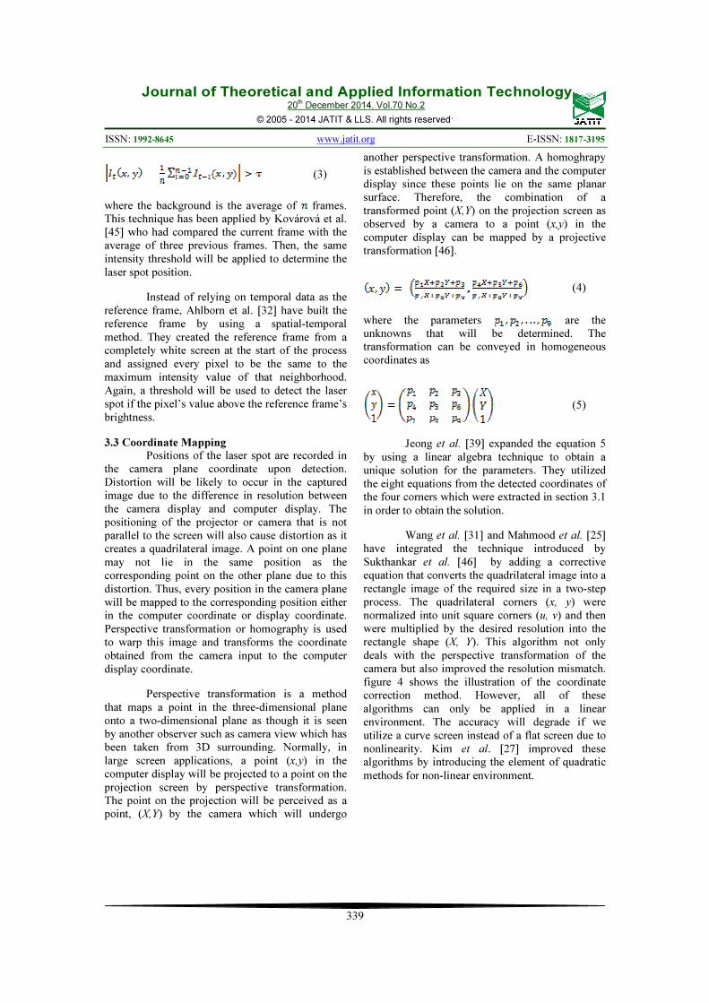
3.3 Coordinate Mapping
Positions of the laser spot are recorded in the camera plane coordinate upon detection. Distortion will be likely to occur in the captured image due to the difference in resolution between the camera display and computer display. The positioning of the projector or camera that is not parallel to the screen will also cause distortion as it creates a quadrilateral image. A point on one plane may not lie in the same position as the corresponding point on the other plane due to this distortion. Thus, every position in the camera plane will be mapped to the corresponding position either in the computer coordinate or display coordinate. Perspective transformation or homography is used to warp this image and transforms the coordinate obtained from the camera input to the computer display coordinate.
Perspective transformation is a method that maps a point in the three-dimensional plane onto a two-dimensional plane as though it is seen by another observer such as camera view which has been taken from 3D surrounding. Normally, in large screen applications, a point (x,y) in the computer display will be projected to a point on the projection screen by perspective transformation. The point on the projection will be perceived as a point, (X,Y) by the camera which will undergo
another perspective transformation. A homoghrapy is established between the camera and the computer display since these points lie on the same planar surface. Therefore, the combination of a transformed point (X,Y) on the projection screen as observed by a camera to a point (x,y) in the computer display can be mapped by a projective transformation [46].
(4)
where the parameters are the unknowns that will be determined. The transformation can be conveyed in homogeneous coordinates as
(5)
Jeong et al. [39] expanded the equation 5
by using a linear algebra technique to obtain a unique solution for the parameters. They utilized the eight equations from the detected coordinates of the four corners which were extracted in section 3.1 in order to obtain the solution.
Wang et al. [31] and Mahmood et al. [25] have integrated the technique introduced by Sukthankar et al. [46] by adding a corrective equation that converts the quadrilateral image into a rectangle image of the required size in a two-step process. The quadrilateral corners (x, y) were normalized into unit square corners (u, v) and then were multiplied by the desired resolution into the rectangle shape (X, Y). This algorithm not only deals with the perspective transformation of the camera but also improved the resolution mismatch. figure 4 shows the illustration of the coordinate correction method. However, all of these algorithms can only be applied in a linear environment. The accuracy will degrade if we utilize a curve screen instead of a flat screen due to nonlinearity. Kim et al. [27] improved these algorithms by introducing the element of quadratic methods for non-linear environment.

Journal of Theoretical and Applied Information Technology 20
th December 2014. Vol.70 No.2
© 2005 - 2014 JATIT & LLS. All rights reserved.
ISSN: 1992-8645 www.jatit.org E-ISSN: 1817-3195
340
Figure 4. Illustration of the coordinate correction method (adapted from Wang et al. [31])
3.4 Laser Spot Interaction
Finally, laser spot interaction can be derived by using the calculated positions and its trend. This step is important so that an autonomous algorithm can be built to translate the intended message form the laser spot movement and positions. The laser spot’s interaction behaviour is usually translated into various actions depending on their applications as shown in Table 1. Generally, there are four modes of operation that a laser pointer can be used to send a message to the observers. The direct mode is as simple as a point-
and-click operation that deals directly with the action being done at the laser spot without applying any complex algorithm. Although the direct mode is easy to use, it has a drawback in the accuracy of distance pointing. A small hand jitter can cause a relatively significant movement of the laser spot from a distance. Besides that, human hands tend to quiver, which will cause the laser beam to be shaky. This hand jittering may lead to selection of an unwanted object when pointing to a small spot from a distance.
Table 1. Laser Spot Operating Modes, Interaction Methods, Behaviour And Actions.
Mode Interaction
method Interaction behaviour Actions done References
Direct Tracked by cursor Cursor was moved to the laser spot, which will replicate mouse function
Mouse left-click, double-click, drag and drop
[25], [37]
Laser spot On/Off Turn laser pointer On/Off to imitate mouse function
Mouse left-click, double left-click, right-click
[27]
Pointing Point to the objects- to do actions; pick up, turn on
Point-and-click [30], [14]
Gesture Stroke Draw strokes to command a robot
deliver, collect, trash
[19]
Sweep pass an area Sweep across a navigating window
For basic presentation manipulation
[28], [47]
Pattern Draw patterns - to imitate mouse function - to command a robot
- Mouse left click, double-click, drag and drop - move robot forward, turn left, turn right
[48], [17]
Display pattern display interactive pattern to represents actions
Tracking, Scrolling, dwell, graffiti
[49]
Multi-
button
Additional buttons on pointer
uPen, CollabPointer Drag and drop on multiple display, support collaboration from multiple pointer
[26], [50]
The gesture and pattern modes may have a more complicated computational algorithm than the
direct mode where the interaction behaviours are more user-friendly. Gesture such as stroke [19] and

Journal of Theoretical and Applied Information Technology 20
th December 2014. Vol.70 No.2
© 2005 - 2014 JATIT & LLS. All rights reserved.
ISSN: 1992-8645 www.jatit.org E-ISSN: 1817-3195
341
sweep [28] did not require precise pointing, which helps abated the jitter problems. Patterns such as triangle, circle and square [17] must be precisely drawn to avoid inaccuracy in evaluating the patterns. The multi-button modes such as uPen [26] and CollabPointer [50] used wireless transmission to transmit the data, which may limit the distance communication distance. A specially designed hardware is required when using multi-button mode, which will increase the implementation cost.
4. OPEN ISSUES WITH LASER SPOT
DETECTION SYSTEM
In previous sections, we have already
discussed the architecture and the methods used in laser spot detection system. A few issues such as illumination change, colour similarity problem and hand jitter has been identified as a result of this study.
Most of the systems were developed in a controlled lighting environment and any variation in lightings will cause a false-off in detecting the laser spot. This problem is more prominent when using the thresholding technique to detect the laser spot. A hybrid technique [14] may be used to solve this problem but the algorithm may be too heavy for a real-time application. Usually, the observed laser spot will be too bright that it will appear as a white spot on the camera image due to saturation of the pixel value. This may lead to miss detection of the spot when it appears on a white background. Furthermore, human weakness that is associated with old age, which is trembling especially when holding an object up for an extended time, may cause the laser spot to appear spasmodic-like. This hand jitter will produce an error, which can be overcome by estimation and smoothing techniques.
5. CONCLUSION
This paper describes the fundamental
construction of a laser spot detection system, which was used in many applications such as laser pointer interaction system, robot manipulation system and remote classroom system. Generally, laser spot detection system by using image processing techniques consists of thresholding, background subtraction and ROI extraction. Most of the algorithms and processing methods used in laser spot detection system were ad hoc in nature and application dependent. The robustness of the algorithm is relatively low, especially for outdoor environment where none of the reviewed
algorithms work well under sudden and local lighting changes. Albeit that, with its high practical value, the laser spot detection system has helped in improving the traditional presentation approach, the domestic lifestyle and many more.
Here, we suggest a few improvements that can be applied in the future to develop an accurate and precise laser spot detection system. A more robust detection algorithm may be used to detect the laser spot in outdoor environment by considering colour transformation method. Colour constancy approach [51] may be applied to accommodate the effect of illumination changes for both local and global cases. In general, colour constancy estimates the colour of the light source and then the input image will be corrected based on a predefined standard illumination by using the estimated illuminant. Besides that, object tracking method based on the deterministic or probabilistic approach [52] can be used to track the laser spot movement. This will indirectly smooth out the movement of the laser spot and helps to reduce the jitter problem. A robust foreground detection method [53] may also be used to improve foreground detection under sudden and gradual illumination change, colour similarity issue, moving background and shadow noise. A jitter reduction method [54] can also be applied to smooth out any sudden movement fluctuation.
REFERENCES
[1] R. A. Karim, N. F. Zakaria, M. A.
Zulkifley, M. M. Mustafa, I. Sagap, and N. H. Md Latar, "Telepointer technology in telemedicine : a review," BioMedical
Engineering OnLine, vol. 12, p. 21, 2013. [2] K. Kyungtae, K. Namgon, H. Sangwoo,
and K. JongWon, "Next-Generation Collaboration Environments for Interactive Tele-medical Consultation," in Biocomputation, Bioinformatics, and
Biomedical Technologies, 2008.
BIOTECHNO '08. International
Conference on, 2008, pp. 143-148. [3] S. Ohta, H. Kuzuoka, M. Noda, H. Sasaki,
S. Mishima, T. Fujikawa, and T. Yukioka, "Remote support for emergency medicine using a remote-control laser pointer," Journal of telemedicine and telecare, vol. 12, pp. 44-48, 2006.
[4] S. Odeh and E. Ketaneh, "E-collaborative remote engineering labs," in Global
Engineering Education Conference
(EDUCON), 2012 IEEE, 2012, pp. 1-10.

Journal of Theoretical and Applied Information Technology 20
th December 2014. Vol.70 No.2
© 2005 - 2014 JATIT & LLS. All rights reserved.
ISSN: 1992-8645 www.jatit.org E-ISSN: 1817-3195
342
[5] P. Gurevich, J. Lanir, B. Cohen, and R. Stone, "TeleAdvisor: a versatile augmented reality tool for remote assistance," presented at the Proceedings of the 2012 ACM annual conference on Human Factors in Computing Systems, Austin, Texas, USA, 2012.
[6] X. Feng-Ying, L. Chang-You, and C. Zhen, "Design of the On-line Interactive Classroom Module for Network Resources Learning Situation," in Education
Technology and Computer Science
(ETCS), 2010 Second International
Workshop on, 2010, pp. 409-412. [7] M. Khan, B. Kosmecki, A. Reutter, C.
Özbek, E. Keeve, and H. Olze, "A Noncontact Laser-Guided System for Endoscopic Computer-Assisted Sinus Surgery," Surgical Innovation, vol. 19, pp. 308-315, September 1, 2012 2012.
[8] A. Q. Ereso, P. Garcia, E. Tseng, M. M. Dua, G. P. Victorino, and L. T. C. T. S. Guy, "Usability of robotic platforms for remote surgical teleproctoring," TELEMEDICINE and e-HEALTH, vol. 15, pp. 445-453, 2009.
[9] A. Schneider, D. Wilhelm, U. Bohn, A. Wichert, and H. Feussner, "An evaluation of a surgical telepresence system for an intrahospital local area network," Journal
of telemedicine and telecare, vol. 11, pp. 408-413, 2005.
[10] C. Chih-Yung, C. Yao-Jiunn, and L. Shing-Yi, "Design and implementation of a vision-based basketball shooting robot," in Mechatronics, 2005. ICM '05. IEEE
International Conference on, 2005, pp. 113-117.
[11] M. V. Mohan, S. A. Devi, C. H. Teena, and A. Abraham, "A method for minimum range extension with improved accuracy in triangulation laser range finder," presented at the Proceedings of the 1st International Conference on Wireless Technologies for Humanitarian Relief, Amritapuri, Kollam, Kerala, India, 2011.
[12] K. Muljowidodo, M. A. Rasyid, N. SaptoAdi, and A. Budiyono, "Vision based distance measurement system using single laser pointer design for underwater vehicle," Indian Journal of Marine
Sciences, vol. 38, pp. 324-331, Sep 2009. [13] M. Takatsuka, G. A. W. West, S.
Venkatesh, and T. M. Caelli, "Low-cost interactive active range finder," Machine
Vision and Applications, vol. 14, pp. 139-144, 2003.
[14] F. Chávez, F. Fernández, R. Alcalá, J. Alcalá-Fdez, G. Olague, and F. Herrera, "Hybrid laser pointer detection algorithm based on template matching and fuzzy rule-based systems for domotic control in real home environments," Applied
Intelligence, vol. 36, pp. 407-423, 2012. [15] F. Chavez, F. Fernandez, R. Alcala, J.
Alcala-Fdez, and F. Herrera, "Evolutionary learning of a laser pointer detection fuzzy system for an environment control system," in Fuzzy Systems (FUZZ),
2011 IEEE International Conference on, 2011, pp. 256-263.
[16] H. Jwu-Sheng and W. Jyun-Ji, "Surface coordinate measurement using un-calibrated cameras and laser pointer equipped robot manipulator," in Advanced
Intelligent Mechatronics (AIM), 2011
IEEE/ASME International Conference on, 2011, pp. 303-308.
[17] Y. Minato, T. Tsujimura, and K. Izumi, "Sign-at-ease: Robot navigation system operated by connoted shapes drawn with laser beam," in SICE Annual Conference
(SICE), 2011 Proceedings of, 2011, pp. 2158-2163.
[18] M. Mikawa, Y. Morimoto, and K. Tanaka, "Guidance method using laser pointer and gestures for librarian robot," in RO-MAN,
2010 IEEE, 2010, pp. 373-378. [19] K. Ishii, S. Zhao, M. Inami, T. Igarashi,
and M. Imai, "Designing Laser Gesture Interface for Robot Control Human-Computer Interaction – INTERACT 2009." vol. 5727, T. Gross, J. Gulliksen, P. Kotzé, L. Oestreicher, P. Palanque, R. Prates, and M. Winckler, Eds., ed: Springer Berlin / Heidelberg, 2009, pp. 479-492.
[20] A. J. Melo Leite Junior, G. A. Menezes Gomes, N. A. Chicca Junior, A. Diniz dos Santos, C. A. Vidal, J. Bento Cavalcante-Neto, and M. Gattass, "System Model for Shooting Training Based on Interactive Video, Three-Dimensional Computer Graphics and Laser Ray Capture," in Virtual and Augmented Reality (SVR),
2012 14th Symposium on, 2012, pp. 254-260.
[21] A. Soetedjo and E. Nurcahyo, "Developing of Low Cost Vision-Based Shooting Range Simulator," IJCSNS

Journal of Theoretical and Applied Information Technology 20
th December 2014. Vol.70 No.2
© 2005 - 2014 JATIT & LLS. All rights reserved.
ISSN: 1992-8645 www.jatit.org E-ISSN: 1817-3195
343
International Journal of Computer Science
and Network Security, vol. 11, pp. 109-113, 2011.
[22] R.-x. Sun and X. Chen, "The Design of the Laser Simulation Training Device," in Knowledge Discovery and Data Mining,
2010. WKDD '10. Third International
Conference on, 2010, pp. 71-74. [23] H.-w. Liang and B. Kong, "A Shooting
Training and Instructing System Based on Image Analysis," in Information
Acquisition, 2006 IEEE International
Conference on, 2006, pp. 961-966. [24] A. K. Bissett, "High Technology War and
'Surgical Strikes'," SIGCAS Comput. Soc.,
vol. 33, p. 4, 2003. [25] M. H. Mahmood, M. A. Khalid, A. G.
Malhi, and A. A. Khan, "A Novel Robust Laser Tracking System with Automatic Environment Adaptation and Keystone Correction," in Image and Graphics
(ICIG), 2011 Sixth International
Conference on, 2011, pp. 743-748. [26] L. Zhang, Y. Shi, and J. Chen, "Drag and
Drop by Laser Pointer: Seamless Interaction with Multiple Large Displays," in Ubiquitous Intelligence and Computing. vol. 4159, J. Ma, H. Jin, L. Yang, and J. Tsai, Eds., ed: Springer Berlin / Heidelberg, 2006, pp. 12-20.
[27] N. Kim, S. Lee, B. Lee, and J. Lee, "Vision Based Laser Pointer Interaction for Flexible Screens," in Human-Computer
Interaction. Interaction Platforms and
Techniques. vol. 4551, J. Jacko, Ed., ed: Springer Berlin / Heidelberg, 2007, pp. 845-853.
[28] Z. Liang, S. Yuanchun, and C. Boliang, "NALP: Navigating Assistant for Large Display Presentation Using Laser Pointer," in Advances in Computer-Human
Interaction, 2008 First International
Conference on, 2008, pp. 39-44. [29] T. Suzuki, A. Ohya, and S. i. Yuta,
"Operation direction to a mobile robot by projection lights," in Advanced Robotics
and its Social Impacts, 2005. IEEE
Workshop on, 2005, pp. 160-165. [30] C. C. Kemp, C. D. Anderson, H. Nguyen,
A. J. Trevor, and Z. Xu, "A point-and-click interface for the real world: laser designation of objects for mobile manipulation," presented at the Proceedings of the 3rd ACM/IEEE international conference on Human robot
interaction, Amsterdam, The Netherlands, 2008.
[31] C. S. Wang, L. P. Hung, S. Y. Peng, and L. C. Cheng, "A Laser Point Interaction System Integrating Mouse Functions," World Academy of Science, Engineering
and Technology, 2010. [32] B. A. Ahlborn, D. Thompson, O. Kreylos,
B. Hamann, and O. G. Staadt, "A practical system for laser pointer interaction on large displays," presented at the Proceedings of the ACM symposium on Virtual reality software and technology, Monterey, CA, USA, 2005.
[33] P. Andriy and S. Wolfgang, "Laser Pointers as Interaction Devices for Collaborative Pervasive Computing," ed, 2004.
[34] K. Fukuchi, "A Laser Pointer/Laser Trails Tracking System for Visual Performance
Human-Computer Interaction - INTERACT 2005." vol. 3585, M. Costabile and F. Paternò, Eds., ed: Springer Berlin / Heidelberg, 2005, pp. 1050-1053.
[35] M. S. Brown and W. K. H. Wong, "Laser pointer interaction for camera-registered multiprojector displays," in Image
Processing, 2003. ICIP 2003.
Proceedings. 2003 International
Conference on, 2003, pp. I-913-16 vol.1. [36] J. F. Lapointe and G. Godin, "On-screen
laser spot detection for large display interaction," in Haptic Audio Visual
Environments and their Applications,
2005. IEEE International Workshop on, 2005, p. 5 pp.
[37] J. Shin, S. Kim, and S. Yi, "Development of Multi-functional Laser Pointer Mouse through Image Processing Multimedia, Computer Graphics and Broadcasting." vol. 262, T.-h. Kim, H. Adeli, W. I. Grosky, N. Pissinou, T. K. Shih, E. J. Rothwell, B.-H. Kang, and S.-J. Shin, Eds., ed: Springer Berlin Heidelberg, 2012, pp. 290-298.
[38] S.-J. Kim, R. Parang, and T.-Y. Kuc, "Laser shot system: a user data input method based on a laser pointer for large screen interactive content," J. Comput.
Small Coll., vol. 25, pp. 152-158, 2009. [39] S. Jeong, C. Jung, C. S. Kim, J. H. Shim,
and M. Lee, "Laser spot detection-based computer interface system using autoassociative multilayer perceptron with input-to-output mapping-sensitive error
Journal of Theoretical and Applied Information Technology 20
th December 2014. Vol.70 No.2
© 2005 - 2014 JATIT & LLS. All rights reserved.
ISSN: 1992-8645 www.jatit.org E-ISSN: 1817-3195
344
back propagation learning algorithm," Optical Engineering, vol. 50, p. 084302, 2011.
[40] S. Sugawara and T. Miki, "A remote lecture system with laser pointer for the Internet and broadband networks," in Applications and the Internet Workshops,
2004. SAINT 2004 Workshops. 2004
International Symposium on, 2004, pp. 61-66.
[41] O. Barnich and M. Van Droogenbroeck, "ViBe: A Universal Background Subtraction Algorithm for Video Sequences," Image Processing, IEEE
Transactions on, vol. 20, pp. 1709-1724, 2011.
[42] T. Du-Ming and L. Shia-Chih, "Independent Component Analysis-Based Background Subtraction for Indoor Surveillance," Image Processing, IEEE
Transactions on, vol. 18, pp. 158-167, 2009.
[43] B. A. Myers, R. Bhatnagar, J. Nichols, C. H. Peck, D. Kong, R. Miller, and A. C. Long, "Interacting at a distance: measuring the performance of laser pointers and other devices," presented at the Proceedings of the SIGCHI conference on Human factors in computing systems: Changing our world, changing ourselves, Minneapolis, Minnesota, USA, 2002.
[44] B. Xia, G. X. Lai, X. R. Ai, Y. Zuo, and X. X. Jiang, "The Research of Application of Laser Pointer Control Projection Screen Menu," Applied Mechanics and Materials,
vol. 145, pp. 214-218, 2012. [45] A. Kovárová, V. Mészáros, and A.
Zelman, "Laser pointer map interaction," presented at the Virtual University 2008: 9th International Conference, Bratislava, Slovakia, 2008.
[46] R. Sukthankar, R. G. Stockton, and M. D. Mullin, "Smarter presentations: exploiting homography in camera-projector systems," in Computer Vision, 2001. ICCV 2001.
Proceedings. Eighth IEEE International
Conference on, 2001, pp. 247-253 vol.1. [47] B. Shizuki, T. Hisamatsu, S. Takahashi,
and J. Tanaka, "Laser pointer interaction techniques using peripheral areas of screens," presented at the Proceedings of the working conference on Advanced visual interfaces, Venezia, Italy, 2006.
[48] S.-P. Li and T. Kvan, "Enhancing Interaction in Architectural Presentations
with Laser Pointers," International
Journal of Architectural Computing, vol. 3, pp. 503-517, 2005.
[49] J. Dan R. Olsen and T. Nielsen, "Laser pointer interaction," presented at the Proceedings of the SIGCHI conference on Human factors in computing systems, Seattle, Washington, United States, 2001.
[50] X. Bi, Y. Shi, X. Chen, and P. Xiang, "Facilitating interaction with large displays in smart spaces," presented at the Proceedings of the 2005 joint conference on Smart objects and ambient intelligence: innovative context-aware services: usages and technologies, Grenoble, France, 2005.
[51] A. Gijsenij, L. Rui, and T. Gevers, "Color Constancy for Multiple Light Sources," Image Processing, IEEE Transactions on,
vol. 21, pp. 697-707, 2012. [52] M. Zulkifley, D. Rawlinson, and B.
Moran, "Robust Observation Detection for Single Object Tracking: Deterministic and Probabilistic Patch-Based Approaches," Sensors, vol. 12, pp. 15638-15670, 2012.
[53] M. A. Zulkifley, B. Moran, and D. Rawlinson, "Robust Foreground Detection: A Fusion of Masked GreyWorld, Probabilistic Gradient Information and Extended Conditional Random Field Approach," Sensors, vol. 12, pp. 5623-5649, 2012.
[54] M. G. Chung and S.-K. Kim, "Efficient jitter compensation using double exponential smoothing," Information
Sciences, vol. 227, pp. 83-89, 2013.


![ISSN: 1992-8645 1817-3195 E-ISSN: HARDWARE-SOFTWARE … · HARDWARE-SOFTWARE SYSTEM FOR MALICIOUS LOGIC DETECTION IN HARDWARE INFRASTRUCTURE OF CARS 1 ... [24-25]. Moreover, some](https://img.pdfslide.us/doc/110x75/5f702b4a6d2c386e565d46ee/issn-1992-8645-1817-e-issn-hardware-software-hardware-software-system-for-malicious.jpg)