Embed Size (px)
Citation preview
Optimal exchanger selection and performance analysis for helium-water heat transfer in fusion energy applications
INTRODUCTION
Plate heat exchangers (PHEs), also called plateand frame heat exchangers are a kind of compactheat exchangers which are quite extensively used inthe chemical process industries. They represent avery good alternative, both with respect to the heattransfer area required and the floor spacerequirements to the more conventional shell and tubeheat exchanges, especially when gas-gas or gas-liquid heat transfer has to be carried out. In the fieldof fusion energy production (e.g. the ITER project[1]),
Karishma Anand1, Rupsha Bhattacharyya2*, K.C.Sandeep2
1Department of Chemical Engineering, Banasthali University, Rajasthan - 304 022, (INDIA)2Heavy Water Division, Bhabha Atomic Research Centre, Mumbai - 400 085, Maharashtra, (INDIA)
E-mail: [email protected]
there is an associated tritium extraction system anda coolant purification system for every tritiumbreeder blanket system[2]. The first wall of thebreeder blanket i.e. the structural elements facingthe plasma chamber must be cooled by high pressurehelium gas which removes the thermal energygenerated during fusion. Helium must then bepurified and freed of contaminants like moisture,hydrogen isotopes, oxygen and nitrogen. For this itis first necessary to depressurize it and cool it downto about ambient conditions. In such systemsassociated with the fusion energy sector, which have
Full Paper
KEYWORDS
Plate heat exchanger;Double pipe exchanger;
Effectiveness;Cost analysis;
Exergy analysis.
ABSTRACT
Plate heat exchangers (PHEs) and double pipe heat exchangers (DPEs)are possible alternatives for gas-liquid heat transfer applications,particularly for relatively low heat duties of the order of few hundredWatt. One such application is cooling of the helium coolant gas used forheat removal from the first wall of tritium breeder blankets in fusionreactors, before the gas is purified. This work illustrates the selection ofan optimal heat exchanger out of PHEs and DPEs for this application basedon the total exchanger cost and floor space requirement. Heat transferarea requirements and pressure drop are predicted using appropriateNusselt number and friction factor correlations. Preliminary costestimations are made by considering the purchase cost of each unit andthe cost of electrical energy required for fluid pumping. Thus the mosteconomical PHE and DPE are identified. The PHE and DPE are thencompared on the basis of space requirements. Effects of various designand operating parameters on the total cost of the optimal exchanger typehave been evaluated. Heat exchanger effectiveness and exergy analyseshave also been performed as part of the rating exercise for the optimalexchanger. 2016 Trade Science Inc. - INDIA
CTAIJ 11(2) 2016 [073-084]
An Indian Journal
Volume 11 Issue 2
chemical technologychemical technologyISSN : 0974 - 7443
id4156328 pdfMachine by Broadgun Software - a great PDF writer! - a great PDF creator! - http://www.pdfmachine.com http://www.broadgun.com
Optimal exchanger selection and performance analysis for helium-water heat transfer74
Full PaperCTAIJ, 11(2) 2016
An Indian Journalchemical technologychemical technology
to be accommodated within limited spaces insideglove boxes to ensure radiation protection and safetyin operation, the heat exchange between gas-liquidstreams is best carried out in compact heatexchangers, owing to the high heat transfercoefficients and consequently the much reduced heattransfer area and floor space requirements. Thereinlies the importance of PHEs for the fusion energyfield. For relatively low heat duties such as in theapplication considered in this study, the moreconventional double pipe heat exchangers (DPEs)also represent a possible class of exchangers thatmay be used[3] and in fact they may be economicallycompetitive with PHEs for gas-liquid service.
In this work, a comparison is made between plateheat exchangers and double pipe heat exchangers forheat duties of upto a few hundred Watt, consideringheat transfer between helium and cooling waterstreams as the case study. Heat exchanger sizingcalculations have been performed using Nusseltnumber correlations specific to each kind of heatexchanger. Economic analysis has been performedto arrive at the optimal PHE and optimal DPEconfiguration for the service considered in this studyand finally the floor space requirements have beencompared for selecting the appropriate exchangerfor this service. For the optimal exchanger,effectiveness analysis and exergy calculations have
also been done to study its performance underconditions different from the design case.
DATA FOR HEAT EXCHANGER SIZING
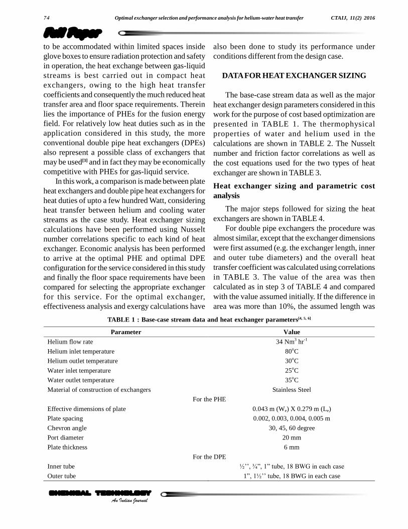
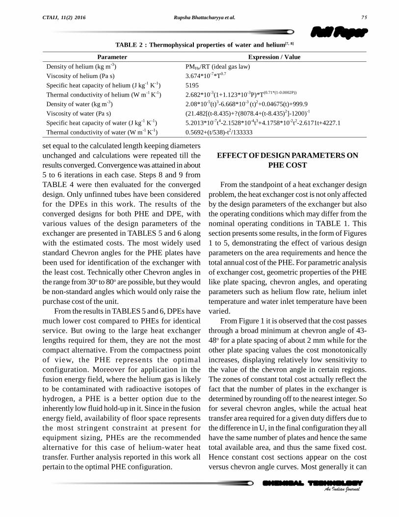
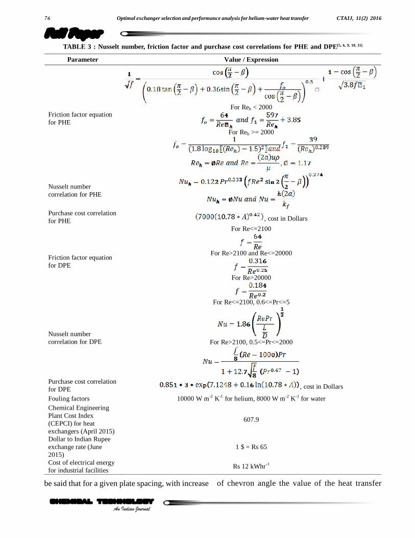
The base-case stream data as well as the majorheat exchanger design parameters considered in thiswork for the purpose of cost based optimization arepresented in TABLE 1. The thermophysicalproperties of water and helium used in thecalculations are shown in TABLE 2. The Nusseltnumber and friction factor correlations as well asthe cost equations used for the two types of heatexchanger are shown in TABLE 3.
Heat exchanger sizing and parametric costanalysis
The major steps followed for sizing the heatexchangers are shown in TABLE 4.
For double pipe exchangers the procedure wasalmost similar, except that the exchanger dimensionswere first assumed (e.g. the exchanger length, innerand outer tube diameters) and the overall heattransfer coefficient was calculated using correlationsin TABLE 3. The value of the area was thencalculated as in step 3 of TABLE 4 and comparedwith the value assumed initially. If the difference inarea was more than 10%, the assumed length was
TABLE 1 : Base-case stream data and heat exchanger parameters[4, 5, 6]
Parameter Value
Helium flow rate 34 Nm3 hr-1
Helium inlet temperature 80oC
Helium outlet temperature 30oC
Water inlet temperature 25oC
Water outlet temperature 35oC
Material of construction of exchangers Stainless Steel
For the PHE
Effective dimensions of plate 0.043 m (We) X 0.279 m (Le)
Plate spacing 0.002, 0.003, 0.004, 0.005 m
Chevron angle 30, 45, 60 degree
Port diameter 20 mm
Plate thickness 6 mm
For the DPE
Inner tube ½��, ¾�, 1� tube, 18 BWG in each case
Outer tube 1�, 1½�� tube, 18 BWG in each case
Rupsha Bhattacharyya et al. 75
Full Paper
chemical technology
CTAIJ, 11(2) 2016
An Indian Journalchemical technology
set equal to the calculated length keeping diametersunchanged and calculations were repeated till theresults converged. Convergence was attained in about5 to 6 iterations in each case. Steps 8 and 9 fromTABLE 4 were then evaluated for the convergeddesign. Only unfinned tubes have been consideredfor the DPEs in this work. The results of theconverged designs for both PHE and DPE, withvarious values of the design parameters of theexchanger are presented in TABLES 5 and 6 alongwith the estimated costs. The most widely usedstandard Chevron angles for the PHE plates havebeen used for identification of the exchanger withthe least cost. Technically other Chevron angles inthe range from 30o to 80o are possible, but they wouldbe non-standard angles which would only raise thepurchase cost of the unit.
From the results in TABLES 5 and 6, DPEs havemuch lower cost compared to PHEs for identicalservice. But owing to the large heat exchangerlengths required for them, they are not the mostcompact alternative. From the compactness pointof view, the PHE represents the optimalconfiguration. Moreover for application in thefusion energy field, where the helium gas is likelyto be contaminated with radioactive isotopes ofhydrogen, a PHE is a better option due to theinherently low fluid hold-up in it. Since in the fusionenergy field, availability of floor space representsthe most stringent constraint at present forequipment sizing, PHEs are the recommendedalternative for this case of helium-water heattransfer. Further analysis reported in this work allpertain to the optimal PHE configuration.
EFFECT OF DESIGN PARAMETERS ONPHE COST
From the standpoint of a heat exchanger designproblem, the heat exchanger cost is not only affectedby the design parameters of the exchanger but alsothe operating conditions which may differ from thenominal operating conditions in TABLE 1. Thissection presents some results, in the form of Figures1 to 5, demonstrating the effect of various designparameters on the area requirements and hence thetotal annual cost of the PHE. For parametric analysisof exchanger cost, geometric properties of the PHElike plate spacing, chevron angles, and operatingparameters such as helium flow rate, helium inlettemperature and water inlet temperature have beenvaried.
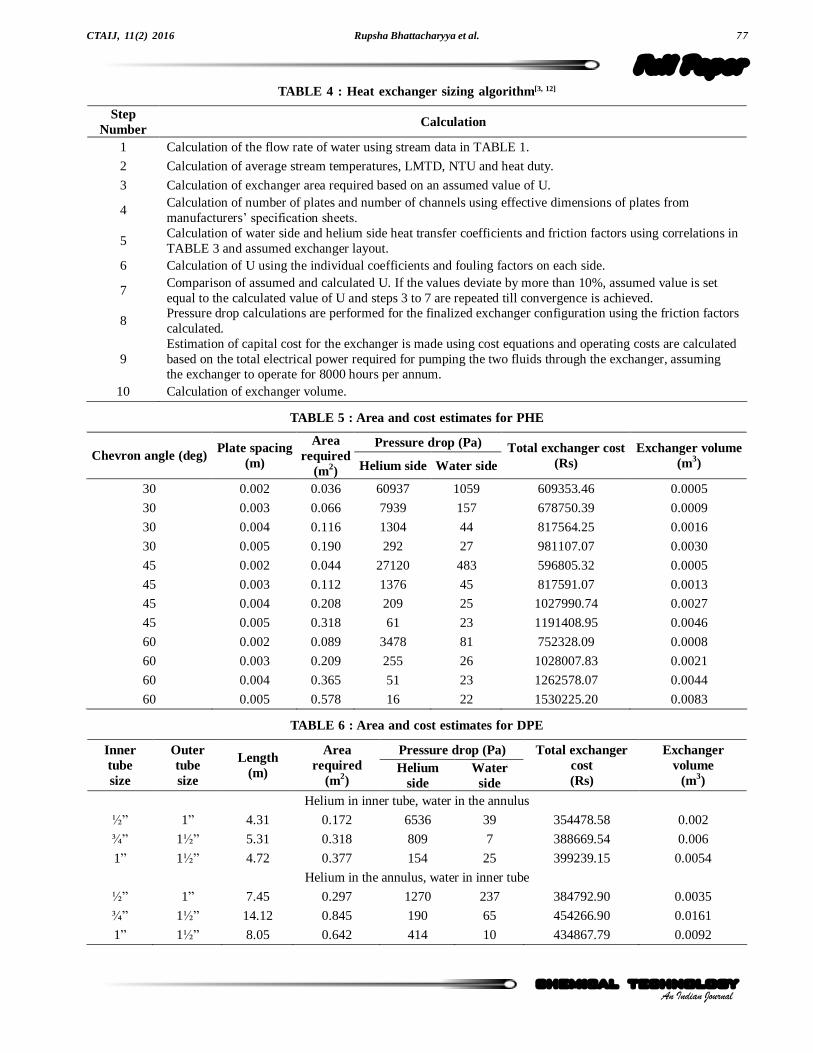
From Figure 1 it is observed that the cost passesthrough a broad minimum at chevron angle of 43-48o for a plate spacing of about 2 mm while for theother plate spacing values the cost monotonicallyincreases, displaying relatively low sensitivity tothe value of the chevron angle in certain regions.The zones of constant total cost actually reflect thefact that the number of plates in the exchanger isdetermined by rounding off to the nearest integer. Sofor several chevron angles, while the actual heattransfer area required for a given duty differs due tothe difference in U, in the final configuration they allhave the same number of plates and hence the sametotal available area, and thus the same fixed cost.Hence constant cost sections appear on the costversus chevron angle curves. Most generally it can
Parameter Expression / Value
Density of helium (kg m-3) PMHe/RT (ideal gas law)
Viscosity of helium (Pa s) 3.674*10-7*T0.7
Specific heat capacity of helium (J kg-1 K-1) 5195
Thermal conductivity of helium (W m-1 K-1) 2.682*10-3(1+1.123*10-3P)*T(0.71*(1-0.0002P))
Density of water (kg m-3) 2.08*10-5(t)3-6.668*10-3 (t)2+0.04675(t)+999.9
Viscosity of water (Pa s) (21.482[(t-8.435)+?(8078.4+(t-8.435)2]-1200)-1
Specific heat capacity of water (J kg-1 K-1) 5.2013*10-7t4-2.1528*10-4t3+4.1758*10-2t2-2.6171t+4227.1
Thermal conductivity of water (W m-1 K-1) 0.5692+(t/538)-t2/133333
TABLE 2 : Thermophysical properties of water and helium[7, 8]
Optimal exchanger selection and performance analysis for helium-water heat transfer76
Full PaperCTAIJ, 11(2) 2016
An Indian Journalchemical technologychemical technology
Parameter Value / Expression
Friction factor equation for PHE
For Reh < 2000
For Reh >= 2000
Nusselt number correlation for PHE
Purchase cost correlation for PHE , cost in Dollars
Friction factor equation for DPE
For Re<=2100
For Re>2100 and Re<=20000
For Re>20000
Nusselt number correlation for DPE
For Re<=2100, 0.6<=Pr<=5
For Re>2100, 0.5<=Pr<=2000
Purchase cost correlation for DPE , cost in Dollars
Fouling factors 10000 W m-2 K-1 for helium, 8000 W m-2 K-1 for water Chemical Engineering Plant Cost Index (CEPCI) for heat exchangers (April 2015)
607.9
Dollar to Indian Rupee exchange rate (June 2015)
1 $ = Rs 65
Cost of electrical energy for industrial facilities
Rs 12 kWhr-1
TABLE 3 : Nusselt number, friction factor and purchase cost correlations for PHE and DPE[5, 6, 9, 10, 11]
be said that for a given plate spacing, with increase of chevron angle the value of the heat transfer
Rupsha Bhattacharyya et al. 77
Full Paper
chemical technology
CTAIJ, 11(2) 2016
An Indian Journalchemical technology
TABLE 4 : Heat exchanger sizing algorithm[3, 12]
Step Number
Calculation
1 Calculation of the flow rate of water using stream data in TABLE 1.
2 Calculation of average stream temperatures, LMTD, NTU and heat duty.
3 Calculation of exchanger area required based on an assumed value of U.
4 Calculation of number of plates and number of channels using effective dimensions of plates from manufacturers� specification sheets.
5 Calculation of water side and helium side heat transfer coefficients and friction factors using correlations in TABLE 3 and assumed exchanger layout.
6 Calculation of U using the individual coefficients and fouling factors on each side.
7 Comparison of assumed and calculated U. If the values deviate by more than 10%, assumed value is set equal to the calculated value of U and steps 3 to 7 are repeated till convergence is achieved.
8 Pressure drop calculations are performed for the finalized exchanger configuration using the friction factors calculated.
9 Estimation of capital cost for the exchanger is made using cost equations and operating costs are calculated based on the total electrical power required for pumping the two fluids through the exchanger, assuming the exchanger to operate for 8000 hours per annum.
10 Calculation of exchanger volume.
Pressure drop (Pa) Chevron angle (deg)
Plate spacing (m)
Area required
(m2) Helium side Water side Total exchanger cost
(Rs) Exchanger volume
(m3)
30 0.002 0.036 60937 1059 609353.46 0.0005
30 0.003 0.066 7939 157 678750.39 0.0009
30 0.004 0.116 1304 44 817564.25 0.0016
30 0.005 0.190 292 27 981107.07 0.0030
45 0.002 0.044 27120 483 596805.32 0.0005
45 0.003 0.112 1376 45 817591.07 0.0013
45 0.004 0.208 209 25 1027990.74 0.0027
45 0.005 0.318 61 23 1191408.95 0.0046
60 0.002 0.089 3478 81 752328.09 0.0008
60 0.003 0.209 255 26 1028007.83 0.0021
60 0.004 0.365 51 23 1262578.07 0.0044
60 0.005 0.578 16 22 1530225.20 0.0083
TABLE 5 : Area and cost estimates for PHE
Pressure drop (Pa) Inner tube size
Outer tube size
Length (m)
Area required
(m2) Helium
side Water
side
Total exchanger cost (Rs)
Exchanger volume
(m3)
Helium in inner tube, water in the annulus
½� 1� 4.31 0.172 6536 39 354478.58 0.002
¾� 1½� 5.31 0.318 809 7 388669.54 0.006
1� 1½� 4.72 0.377 154 25 399239.15 0.0054
Helium in the annulus, water in inner tube
½� 1� 7.45 0.297 1270 237 384792.90 0.0035
¾� 1½� 14.12 0.845 190 65 454266.90 0.0161
1� 1½� 8.05 0.642 414 10 434867.79 0.0092
TABLE 6 : Area and cost estimates for DPE
Optimal exchanger selection and performance analysis for helium-water heat transfer78
Full PaperCTAIJ, 11(2) 2016
An Indian Journalchemical technologychemical technology
coefficient decreases, so a higher heat transfer areais required for the given heat duty. For a givenchevron angle, increasing the plate spacing reducesthe fluid velocities per pass and lowers the heattransfer coefficients, which once again necessitatesa higher heat transfer area and consequently a higherexchanger cost. The lowered cost of fluid pumpingon increasing the plate spacing does not affect the
total cost significantly since the pressure drop andthe pumping power cost is a very small fraction ofthe total cost, owing to the low gas and liquid flowrates considered in this work.
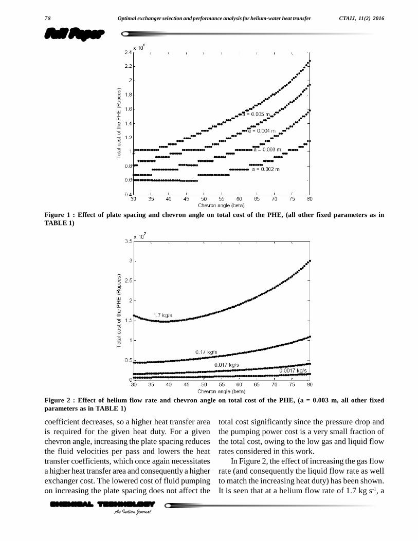
In Figure 2, the effect of increasing the gas flowrate (and consequently the liquid flow rate as wellto match the increasing heat duty) has been shown.It is seen that at a helium flow rate of 1.7 kg s-1, a
Figure 1 : Effect of plate spacing and chevron angle on total cost of the PHE, (all other fixed parameters as inTABLE 1)
Figure 2 : Effect of helium flow rate and chevron angle on total cost of the PHE, (a = 0.003 m, all other fixedparameters as in TABLE 1)
Rupsha Bhattacharyya et al. 79
Full Paper
chemical technology
CTAIJ, 11(2) 2016
An Indian Journalchemical technology
minimum appears in the total cost at a chevron angleof about 37o for a plate spacing of 3 mm. At a givenflow rate, with increase of chevron angle, the heattransfer coefficient and the friction factor (hencethe pressure drop) both decrease. When flow ratesand hence heat transfer coefficients and pressuredrops are low, in general the total cost increasesmonotonically with increasing chevron angle, since
fluid pumping costs are not significant and the totalcost is controlled by the the fixed cost. But whenflow rates are high, fluid pumping costs arecomparable with the fixed cost of the exchangerand upto a certain value of the chevron angle, thelowered pumping cost outweighs the enhanced arearequirements and hence the total cost is seen todecrease. Beyond this angle the rise in fixed cost
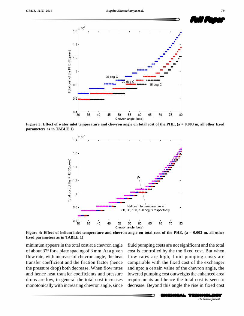
Figure 3: Effect of water inlet temperature and chevron angle on total cost of the PHE, (a = 0.003 m, all other fixedparameters as in TABLE 1)
Figure 4: Effect of helium inlet temperature and chevron angle on total cost of the PHE, (a = 0.003 m, all otherfixed parameters as in TABLE 1)
Optimal exchanger selection and performance analysis for helium-water heat transfer80
Full PaperCTAIJ, 11(2) 2016
An Indian Journalchemical technologychemical technology
is greater than that in the pumping cost and thetotal cost again increases with chevron angle. Itis also possible that the total cost decreases withchevron angle, if fluid pumping cost issignificantly greater than the fixed cost of theexchanger. In arriving at the results of Figure 3,the size of each plate was kept the same for allcases, to ensure uniformity in cost comparison. Butfor an actual heat exchanger handling these muchenhanced fluid flow rates, larger plates, based onthe available standard sizes will actually have tobe used, so that the required heat transfer area isobtained with fewer number of plates, which in turnimplies higher channel velocity of the fluids, a largerU and lower cost.
Figure 3 shows that lower the cooling water inlettemperature, lower is the exchanger cost since agreater temperature difference driving force isavailable for heat transfer to take place. In Figure 4,the change in the inlet temperature of helium is seento affect the total exchanger cost to a much lowerextent than the change in the cooling water inlettemperature. Higher helium inlet temperature at agiven flow rate and a fixed outlet temperatureindicates a higher heat duty but also a higher meantemperature difference for heat transfer. Thus the arearequirements are not dramatically increased with risein helium temperature. In Figure 5, the effect of
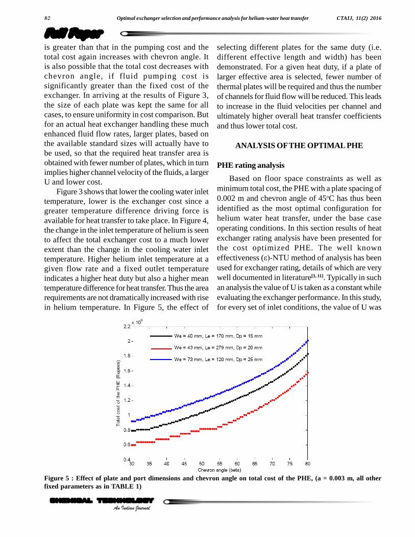
selecting different plates for the same duty (i.e.different effective length and width) has beendemonstrated. For a given heat duty, if a plate oflarger effective area is selected, fewer number ofthermal plates will be required and thus the numberof channels for fluid flow will be reduced. This leadsto increase in the fluid velocities per channel andultimately higher overall heat transfer coefficientsand thus lower total cost.
ANALYSIS OF THE OPTIMAL PHE
PHE rating analysis
Based on floor space constraints as well asminimum total cost, the PHE with a plate spacing of0.002 m and chevron angle of 45oC has thus beenidentified as the most optimal configuration forhelium water heat transfer, under the base caseoperating conditions. In this section results of heatexchanger rating analysis have been presented forthe cost optimized PHE. The well knowneffectiveness (å)-NTU method of analysis has beenused for exchanger rating, details of which are verywell documented in literature[3, 11]. Typically in suchan analysis the value of U is taken as a constant whileevaluating the exchanger performance. In this study,for every set of inlet conditions, the value of U was
Figure 5 : Effect of plate and port dimensions and chevron angle on total cost of the PHE, (a = 0.003 m, all otherfixed parameters as in TABLE 1)
Rupsha Bhattacharyya et al. 81
Full Paper
chemical technology
CTAIJ, 11(2) 2016
An Indian Journalchemical technology
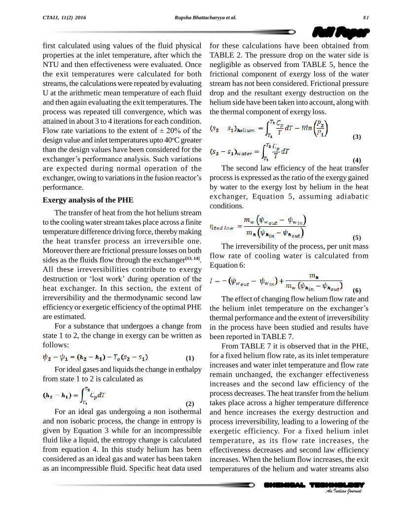
first calculated using values of the fluid physicalproperties at the inlet temperature, after which theNTU and then effectiveness were evaluated. Oncethe exit temperatures were calculated for bothstreams, the calculations were repeated by evaluatingU at the arithmetic mean temperature of each fluidand then again evaluating the exit temperatures. Theprocess was repeated till convergence, which wasattained in about 3 to 4 iterations for each condition.Flow rate variations to the extent of ± 20% of the
design value and inlet temperatures upto 40oC greaterthan the design values have been considered for theexchanger�s performance analysis. Such variations
are expected during normal operation of theexchanger, owing to variations in the fusion reactor�sperformance.
Exergy analysis of the PHE
The transfer of heat from the hot helium streamto the cooling water stream takes place across a finitetemperature difference driving force, thereby makingthe heat transfer process an irreversible one.Moreover there are frictional pressure losses on bothsides as the fluids flow through the exchanger[13, 14].All these irreversibilities contribute to exergydestruction or �lost work� during operation of the
heat exchanger. In this section, the extent ofirreversibility and the thermodynamic second lawefficiency or exergetic efficiency of the optimal PHEare estimated.
For a substance that undergoes a change fromstate 1 to 2, the change in exergy can be written asfollows:
(1)
For ideal gases and liquids the change in enthalpyfrom state 1 to 2 is calculated as
(2)For an ideal gas undergoing a non isothermal
and non isobaric process, the change in entropy isgiven by Equation 3 while for an incompressiblefluid like a liquid, the entropy change is calculatedfrom equation 4. In this study helium has beenconsidered as an ideal gas and water has been takenas an incompressible fluid. Specific heat data used
for these calculations have been obtained fromTABLE 2. The pressure drop on the water side isnegligible as observed from TABLE 5, hence thefrictional component of exergy loss of the waterstream has not been considered. Frictional pressuredrop and the resultant exergy destruction on thehelium side have been taken into account, along withthe thermal component of exergy loss.
(3)
(4)The second law efficiency of the heat transfer
process is expressed as the ratio of the exergy gainedby water to the exergy lost by helium in the heatexchanger, Equation 5, assuming adiabaticconditions.
(5)The irreversibility of the process, per unit mass
flow rate of cooling water is calculated fromEquation 6:
(6)The effect of changing flow helium flow rate and
the helium inlet temperature on the exchanger�sthermal performance and the extent of irreversibilityin the process have been studied and results havebeen reported in TABLE 7.
From TABLE 7 it is observed that in the PHE,for a fixed helium flow rate, as its inlet temperatureincreases and water inlet temperature and flow rateremain unchanged, the exchanger effectivenessincreases and the second law efficiency of theprocess decreases. The heat transfer from the heliumtakes place across a higher temperature differenceand hence increases the exergy destruction andprocess irreversibility, leading to a lowering of theexergetic efficiency. For a fixed helium inlettemperature, as its flow rate increases, theeffectiveness decreases and second law efficiencyincreases. When the helium flow increases, the exittemperatures of the helium and water streams also

Optimal exchanger selection and performance analysis for helium-water heat transfer82
Full PaperCTAIJ, 11(2) 2016
An Indian Journalchemical technologychemical technology
increase, thereby giving rise to higher processirreversibility, but the gain in exergy of the waterstream rises as its flow rate and inlet temperatureremain unchanged, thereby raising the exergeticefficiency of the process. Not considering thefrictional loss of exergy on the helium side leads tocalculated second law efficiency greater by about 1to 2% compared to the values in TABLE 7. Thecooling water is obtained from the ambient and itsinlet temperature may vary seasonally. At atemperature of 15oC, which is lower than the deadstate temperature of 20oC considered here, it is seenthat exergetic efficiency drops drastically, owing tomuch larger exergy loss by helium and relativelylow exergy gain by the water stream.
SUMMARY AND CONCLUSIONS
Comparative total cost analysis has been usedas the basis for optimizing PHEs and DPEs for thecase of helium water heat transfer. This has practicalrelevance to the field of fusion energy. The mostsimple exchanger types have been studied here toallow a preliminary identification of the optimal
type. The cost was estimated from the thermal designof the exchanger without detailed mechanical designconsiderations. It was determined that while the costof the DPE is much lower than that of the PHE for agiven service, the space requirement is much largerfor the DPE and hence it is not the optimal choicefor fusion energy applications where spacerequirements appear as the most stringent constraint.It is expected that use of finned inner tubes willreduce the DPE dimensions but also increase thecost slightly. Thus the PHE was chosen as the optimalexchanger for helium water service and its designparameters were selected on the basis of minimumtotal annual cost. For the optimal PHE, performanceanalysis for operating conditions other than the designvalues was carried out using the å-NTU method. Truecounter flow characteristics of the exchanger wereassumed for it. Effectiveness values were quite high,ranging from 0.94 to 0.98 for the conditionsexamined. Exergy analysis was also performed forthe exchanger, and exergetic efficiency was found tolie between 9 and 35%, assuming adiabaticoperation.
Helium flow rate
(kg s-1)
Helium inlet temperature
(oC)
Cooling water flow rate
(kg s-)
Cooling water inlet
temperature (oC)
NTU å
Helium outlet
temperature (oC)
Cooling water outlet temperature
(oC)
Process Irreversibility per kg water (J kg-1 water)
Process second
law efficiency
(%) 0.0017 90 0.0106 25 3.9608 0.9661 27.20 37.51 4052 32.52
0.0017 100 0.0106 25 3.9754 0.9665 27.51 39.44 5264 31.63
0.0017 110 0.0106 25 3.9898 0.9669 27.81 41.37 6604 30.98
0.0017 120 0.0106 25 4.0041 0.9673 28.11 43.29 8064 30.51
0.00136 90 0.0106 25 4.4310 0.9797 26.32 35.14 3380 29.68
0.00136 100 0.0106 25 4.4461 0.9799 36.51 36.71 4398 28.67
0.00136 110 0.0106 25 4.4610 0.9802 26.69 38.27 5524 27.91
0.00136 120 0.0106 25 4.4758 0.9804 26.86 39.83 6753 27.35
0.00204 90 0.0106 25 3.5668 0.9488 28.33 39.74 4679 34.96
0.00204 100 0.0106 25 3.5813 0.9493 28.79 42.01 6069 34.19
0.00204 110 0.0106 25 3.5956 0.9499 29.26 44.29 7604 33.65
0.00204 120 0.0106 25 3.6099 0.9505 29.71 46.58 9274 33.26
0.0017 90 0.0106 15 3.8811 0.9639 17.71 29.39 5606 7.69
0.0017 100 0.0106 15 3.8962 0.9643 18.03 31.32 7023 9.59
0.0017 110 0.0106 15 3.9112 0.9648 18.35 33.25 8579 11.13
0.0017 120 0.0106 15 3.9261 0.9652 18.66 35.18 10245 12.41
TABLE 7 : Results of the PHE rating and exergy analysis (To = 293 K)
Rupsha Bhattacharyya et al. 83
Full Paper
chemical technology
CTAIJ, 11(2) 2016
An Indian Journalchemical technology
Nomenclature
a Plate spacing (m)
A Heat exchanger area (m2)
Cp Specific heat capacity (J kg-1 K-1)
D Tube diameter (m)
Dp Port diameter for PHE (m)
f Friction factor
fo, f1 Constants for friction factor correlation
h Convective heat transfer coefficient (W m-2 K-1)
h1, h2 Specific enthalpy of a fluid stream at state 1 and 2 respectively (J kg-1)
I Process irreversibility per unit mass of water (J kg-1)
kf Fluid thermal conductivity (W m-1 K-1)
L Length of heat exchanger (m)
Le Effective length of heat exchanger plate (m)
mh Helium mass flow rate (kg s-1)
mw Water mass flow rate (kg s-1)
MHe Helium molecular weight (kg mol-1)
Nu Nusselt number
Nuh Modified Nusselt number for PHE
NTU Number of transfer units in the heat exchanger
P Fluid pressure (bar)
P1, P2 Fluid pressure at state 1 and 2 respectively (bar)
Pr Prandtl number
R Gas constant for helium (J kg-1 K-1)
Re Reynolds number
Reh Modified Reynolds number for PHE
s1, s2 Specific entropy of a fluid stream at state 1 and 2 respectively (J kg-1 K-1)
t Stream temperature (Celsius)
T Stream temperature (K)
To Ambient temperature (K)
u Channel velocity in PHE (m s-1)
U Overall heat transfer coefficient in an exchanger (W m-2 K-1)
å Heat exchanger effectiveness
ø1, ø2 Specific availability of a fluid stream at state 1 and 2 respectively (J kg-1)
øh in, øh out Specific availability of helium at state 1 and 2 respectively (J kg-1)
øw in, øw out Specific availability of water at state 1 and 2 respectively (J kg-1)
ç2nd law Second law thermodynamic efficiency
ñ Fluid density (kg m-3)
ì Fluid viscosity (Pa s)
ö Surface enhancement factor for PHE
REFERENCES
[1] N.Holtkamp; �An overview of the ITER project�,
Fusion Engineering and Design, 82(5-14), 427-434(2013).
[2] A.Ciampichetti, F.S.Nitti, A.Aiello, I.Ricapito,K.Liger, D.Demange, L.Sedano, C.Moreno,M.Succi; �Conceptual design of tritium extraction
system for the european HCPB test blanket module�,Fusion Engineering and Design, 87(5-6), 466-471(2012).

Optimal exchanger selection and performance analysis for helium-water heat transfer84
Full PaperCTAIJ, 11(2) 2016
An Indian Journalchemical technologychemical technology
[3] B.K.Dutta; Heat transfer principles and applications,Prentice Hall of India Pvt.Ltd., (2006).
[4] GBS series � brazed plate heat exchangers technical
data sheet, Available at http://www.gea-heatexchangers.com/products/plate-heat-exchangers/brazed-plate-heat-exchangers/gbs-series/, lastaccessed on 03.08.2015.
[5] S.Kakac, H.Liu, A.Pramuanjaroenkij; Heatexchangers: Selection, Rating, and thermal design,3rd Edition, CRC press, Taylor and Francis Group,(2012).
[6] L.Wang, B.Sunden, R.M.Manglik; Plate heatexchangers: Design, Applications and Performance,WIT Press, (2007).
[7] H.Petersen; �The properties of helium: Density,
Specific heats, Viscosity, and thermal conductivityat pressures from 1 to 100 bar and from roomtemperature to about 1800 K�, Report No.224,
Danish atomic energy commission researchestablishment riso, (1970).
[8] J.A.W.Gut, J.M.Pinto, �Modeling of plate heat
exchangers with generalized conûgurations�,
International Journal of Heat and Mass Transfer,46, 2571-2581 (2003).
[9] W.D.Seider, J.D.Seader, D.R.Lewin; Product andprocess design principles � synthesis, Analysis and
Evaluation, 2nd Edition, John Wiley and Sons Inc.,(2009).
[10] Chemical Engineering, 122(7), 64, July, (2015).[11] F.P.Incropera, D.P.De Witt, T.L.Bergman,
A.S.Lavine; Fundamentals of heat and mass transfer,6th Edition, John Wiley and Sons Inc., (2006).
[12] G.Towler, R.Sinnott, Chemical engineering design -Principles, Practice and economics of plant andprocess design, Elsevier Inc., (2008).
[13] R.E.Sonntag, C.Borgnakke, G.J.Van Wylen;Fundamentals of thermodynamics, 6th Edition, JohnWiley and Sons Inc., (2005).
[14] T.J.Kotas; The exergy method of thermal plantanalysis, 1st Edition, Krieger Publishing Company,(1995).


![ISSN 0367-8288 (PRINT) ISSN 0974-8172 (ONLINE) INDIAN ...oar.icrisat.org/11672/1/ESI IJE- 82(3)[23821]-pages-1...Indian Journal of Entomology 82(3): 543-546 (2020) DoI No.: 10.5958/0974-8172.2020.00135.2](https://img.pdfslide.us/doc/110x75/6129929f4d175b598a5422ca/issn-0367-8288-print-issn-0974-8172-online-indian-oar-ije-82323821-pages-1.jpg)