Embed Size (px)
Citation preview

Full Terms & Conditions of access and use can be found athttp://www.tandfonline.com/action/journalInformation?journalCode=tjhr20
Download by: [eFada - UAE] Date: 11 July 2016, At: 08:06
Journal of Hydraulic Research
ISSN: 0022-1686 (Print) 1814-2079 (Online) Journal homepage: http://www.tandfonline.com/loi/tjhr20
Performance characteristics of water wheels
Gerald Müller & Klemens Kauppert
To cite this article: Gerald Müller & Klemens Kauppert (2004) Performancecharacteristics of water wheels, Journal of Hydraulic Research, 42:5, 451-460, DOI:10.1080/00221686.2004.9641215
To link to this article: http://dx.doi.org/10.1080/00221686.2004.9641215
Published online: 03 Dec 2010.
Submit your article to this journal
Article views: 327
View related articles
Citing articles: 11 View citing articles
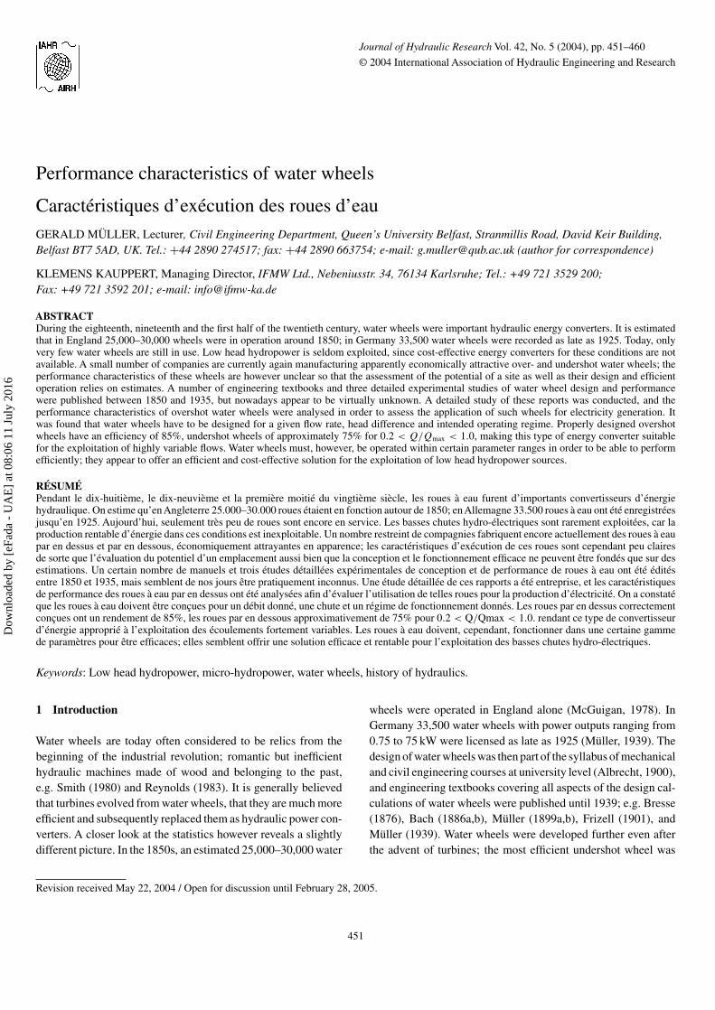
Journal of Hydraulic Research Vol. 42, No. 5 (2004), pp. 451–460
© 2004 International Association of Hydraulic Engineering and Research
Performance characteristics of water wheels
Caractéristiques d’exécution des roues d’eauGERALD MÜLLER, Lecturer, Civil Engineering Department, Queen’s University Belfast, Stranmillis Road, David Keir Building,Belfast BT7 5AD, UK. Tel.: +44 2890 274517; fax: +44 2890 663754; e-mail: [email protected] (author for correspondence)
KLEMENS KAUPPERT, Managing Director, IFMW Ltd., Nebeniusstr. 34, 76134 Karlsruhe; Tel.: +49 721 3529 200;Fax: +49 721 3592 201; e-mail: [email protected]
ABSTRACTDuring the eighteenth, nineteenth and the first half of the twentieth century, water wheels were important hydraulic energy converters. It is estimatedthat in England 25,000–30,000 wheels were in operation around 1850; in Germany 33,500 water wheels were recorded as late as 1925. Today, onlyvery few water wheels are still in use. Low head hydropower is seldom exploited, since cost-effective energy converters for these conditions are notavailable. A small number of companies are currently again manufacturing apparently economically attractive over- and undershot water wheels; theperformance characteristics of these wheels are however unclear so that the assessment of the potential of a site as well as their design and efficientoperation relies on estimates. A number of engineering textbooks and three detailed experimental studies of water wheel design and performancewere published between 1850 and 1935, but nowadays appear to be virtually unknown. A detailed study of these reports was conducted, and theperformance characteristics of overshot water wheels were analysed in order to assess the application of such wheels for electricity generation. Itwas found that water wheels have to be designed for a given flow rate, head difference and intended operating regime. Properly designed overshotwheels have an efficiency of 85%, undershot wheels of approximately 75% for 0.2 < Q/Qmax < 1.0, making this type of energy converter suitablefor the exploitation of highly variable flows. Water wheels must, however, be operated within certain parameter ranges in order to be able to performefficiently; they appear to offer an efficient and cost-effective solution for the exploitation of low head hydropower sources.
RÉSUMÉPendant le dix-huitième, le dix-neuvième et la première moitié du vingtième siècle, les roues à eau furent d’importants convertisseurs d’énergiehydraulique. On estime qu’en Angleterre 25.000–30.000 roues étaient en fonction autour de 1850; en Allemagne 33.500 roues à eau ont été enregistréesjusqu’en 1925. Aujourd’hui, seulement très peu de roues sont encore en service. Les basses chutes hydro-électriques sont rarement exploitées, car laproduction rentable d’énergie dans ces conditions est inexploitable. Un nombre restreint de compagnies fabriquent encore actuellement des roues à eaupar en dessus et par en dessous, économiquement attrayantes en apparence; les caractéristiques d’exécution de ces roues sont cependant peu clairesde sorte que l’évaluation du potentiel d’un emplacement aussi bien que la conception et le fonctionnement efficace ne peuvent être fondés que sur desestimations. Un certain nombre de manuels et trois études détaillées expérimentales de conception et de performance de roues à eau ont été éditésentre 1850 et 1935, mais semblent de nos jours être pratiquement inconnus. Une étude détaillée de ces rapports a été entreprise, et les caractéristiquesde performance des roues à eau par en dessus ont été analysées afin d’évaluer l’utilisation de telles roues pour la production d’électricité. On a constatéque les roues à eau doivent être conçues pour un débit donné, une chute et un régime de fonctionnement donnés. Les roues par en dessus correctementconçues ont un rendement de 85%, les roues par en dessous approximativement de 75% pour 0.2 < Q/Qmax < 1.0. rendant ce type de convertisseurd’énergie approprié à l’exploitation des écoulements fortement variables. Les roues à eau doivent, cependant, fonctionner dans une certaine gammede paramètres pour être efficaces; elles semblent offrir une solution efficace et rentable pour l’exploitation des basses chutes hydro-électriques.
Keywords: Low head hydropower, micro-hydropower, water wheels, history of hydraulics.
1 Introduction
Water wheels are today often considered to be relics from thebeginning of the industrial revolution; romantic but inefficienthydraulic machines made of wood and belonging to the past,e.g. Smith (1980) and Reynolds (1983). It is generally believedthat turbines evolved from water wheels, that they are much moreefficient and subsequently replaced them as hydraulic power con-verters. A closer look at the statistics however reveals a slightlydifferent picture. In the 1850s, an estimated 25,000–30,000 water
Revision received May 22, 2004 / Open for discussion until February 28, 2005.
451
wheels were operated in England alone (McGuigan, 1978). InGermany 33,500 water wheels with power outputs ranging from0.75 to 75 kW were licensed as late as 1925 (Müller, 1939). Thedesign of water wheels was then part of the syllabus of mechanicaland civil engineering courses at university level (Albrecht, 1900),and engineering textbooks covering all aspects of the design cal-culations of water wheels were published until 1939; e.g. Bresse(1876), Bach (1886a,b), Müller (1899a,b), Frizell (1901), andMüller (1939). Water wheels were developed further even afterthe advent of turbines; the most efficient undershot wheel was
Dow
nloa
ded
by [
eFad
a -
UA
E]
at 0
8:06
11
July
201
6

452 Müller and Kauppert
only patented in 1883. Engineers, manufacturers and mill ownersclearly regarded water wheels as efficient and commercially inter-esting power sources. The water wheels were almost exclusivelyemployed as mechanical power sources driving grist-, powder-,and mineral mills as well as textile and other machinery, mostlyin small businesses. With the advent of the electric motor as acheap power source, however, in the 1940s and 1950s, the waterwheels disappeared virtually completely.
Today, the requirement for the utilization of low headhydropower sources for electricity generation is greater than ever.In the industrialized countries, the demand for renewable energysources is constantly increasing in order to meet non-fossil fueltargets. The currently unused low head micro-hydro potential isestimated as 500 MW in Germany and around 600–1000 MWin the UK (König and Jehle, 1997; Goring, 2000). In develop-ing countries, the rising demand for electricity in combinationwith large distances means that decentralized electricity gener-ation has a high priority. Most low head, low flow hydropowersources, however, are not exploited in recent times since standardturbines cannot be employed economically in such conditions.Consequently, there exists a demand for a cost-effective low headhydraulic energy converter, which still could not be met. Waterwheels may offer an attractive solution to this problem. A smallnumber of companies in Germany and the USA are again man-ufacturing water wheels for electricity generation, see Internetreferences. For an overview of the current water wheel types andtheir utilization today, see Müller and Kauppert (2002). The per-formance characteristics of such wheels, however, still appearto be largely unknown, so that the assessment of the availablepower potential, comparisons with other turbine types such as theKaplan or the Ossberger (crossflow) turbine and even the deter-mination of optimum operating conditions for water wheels relieson estimates. Most modern hydraulic engineering textbooks donot even mention water wheels any more, and if they do, theyprovide very little information on the performance and design,e.g. König and Jehle (1997) and Giesecke and Mosónyi (1998).
Although a significant amount of information about waterwheels still exists, it is often hidden in old textbooks and longforgotten reports. The authors set up a small non-profit researchcompany (IFMW Ltd.) in Karlsruhe, Germany, which specializesin hydraulic engineering research. Within the company, the avail-able engineering literature on water wheels was collected andanalysed in order to establish the design and performance char-acteristics of “modern” water wheels. In this article, the resultsof this review will be presented.
2 Types of water wheels
In order to be able to utilize the head differences from 0.5 toaround 12 m, different types of water wheels were developed andperfected during the nineteenth century:
1. Overshot water wheels, Fig. 1(a): the water enters the wheelfrom above. This wheel type was employed for head differ-ences of 2.5–10 m, and flow rates of 0.1–0.2 m3/s per metrewidth.
2. Breast wheels, Fig. 1(b): the level of the upstream water tablelies at approximately the level of the wheel’s axis. This wheeltype was mostly used for head differences of 1.5–4 m, andflow rates of 0.35–0.65 m3/s per metre width.
3. Undershot or Zuppinger wheels, Fig. 1(c): the water entersthe wheel below its axis. This wheel type can be used for verysmall head differences of 0.5–2.5 m, and large flow volumesranging from 0.5–0.95 m3/s per metre width.
Between these wheel types, a large number of intermediateforms existed. What all “modern” wheels have in common is thatthey employ the potential energy of the water, they operate underatmospheric pressure and that they are built of steel. Impulsetype wheels, which use the kinetic energy of flowing water werealso built occasionally, although it was well known that their effi-ciencies were too low to be used economically except in speciallocations; see, e.g. Müller (1899a). The different wheel typeshave different characteristics in the way the function, they per-form and the way they are designed. In the following, the wheeltypes and their performance characteristics—as far as they areknown—will be described.
3 The overshot wheel
3.1 Principles
An overshot water wheel installation consists of three elements:inflow detail, water wheel and tailwater channel. “Modern” over-shot water wheels are made of steel and feature a very distinctivegeometry of the cells as well as a specially designed inflow detail.Figure 2 shows a typical overshot wheel with a close-up of aninflow detail. The wheel in Fig. 2(a) has a weir type inflow with-out controlling elements, so that the upstream water level andthe velocity of the inflowing water particles are a function of theflow volume. The inflow detail shown in Fig. 2(b) consists of achannel with inflow slots, the area of which can be regulated, atthe bottom. The slots are shaped so as to direct the water at theright angle into the cells. Here, the upstream water level (and thevelocity of the inflowing water) can be kept constant. A somewhatsimilar inflow detail, with a sluice gate, can be seen in Fig. 1(a).The cells themselves are formed in a way so that the water jet canenter each cell at its natural angle of fall. The opening of eachcell is slightly wider than the jet, so that the air can escape. Thecells are however kept as narrow as possible so that the weightof the water can become effective almost immediately. In orderto avoid an early loss of water, each cell should only be filledwith up to 30–50% of its volume. For a detailed discussion of theoptimum cell geometry see Bach (1886a); an English translationof the relevant section is contained in Weidner (1913).
The peculiar shape of the cells retains the water inside of thecell until the lowermost position, when it finally empties rapidly.In the overshot wheel, it is thus the potential energy of the waterthat constitutes the driving force for the wheel. Figure 1(a) alsoillustrates the in- and outflow condition. The wheel has a regu-lated inflow with a sluice gate, so that the inflowing water entersthe cells as a fast and thin sheet; the outflow only starts at a very
Dow
nloa
ded
by [
eFad
a -
UA
E]
at 0
8:06
11
July
201
6

Performance characteristics of water wheels 453
(a)
(c)
(b)
Figure 1 Types of water wheels: (a) overshot wheel (Müller, 1899a); (b) breast wheel (Fairbairn, 1849); (c) undershot (Zuppinger) wheel (Müller,1899a).
(a)
(b)
Figure 2 Overshot cell wheel (Müller, 1939): (a) cell wheel with free inflow; (b) cells and inflow detail.
low level. No water is carried over the lowermost point. Figure 3shows an old and a modern overshot water wheel.
3.2 Hydraulic design
Water wheels are designed for a given application, head differ-ence and flow volume. For the design of an overshot water wheel,the diameter is determined by the head difference, although it
has to be decided whether the wheel will be operated with freeor regulated inflow (i.e. constant or variable speed) since thisaffects the available head. The wheel speed and the number, depthand shape of the cells then has to be determined as well as thewidth of the wheel for a given design flow volume and wheelspeed. The inflow detail with or without a sluice gate has to bedesigned so that the design flow volume can be guided into thewheel.
Dow
nloa
ded
by [
eFad
a -
UA
E]
at 0
8:06
11
July
201
6

454 Müller and Kauppert
(a) (b)
Figure 3 Overshot wheels: (a) with sluice gate entry detail, USA, ca. 1900; (b) with free inflow, 2.9 m diameter, 4 m width, 26 kW (el.),Hydrowatt Ltd., 2000.
4 Performance characteristics of overshot water wheels
4.1 General
The complex in- and outflow conditions in an overshot waterwheel have so far prevented the development of a theoreticalmodel of the water wheel and its characteristics. The actualefficiency and performance characteristics of water wheels cantherefore only be determined by tests. Although a large numberof wheels were in operation in the last century, only three series ofsuch tests appear to have been performed, the key results of whichwill be presented in the following. Most of the test results werenever published in hydraulic engineering textbooks or journalsand are only available in not so widely known articles and reports;see Weidner (1913a,b), Staus (1928) and Meerwarth (1935). Tothe authors’ knowledge, Staus’ results were never published inEnglish, and Meerwarth’s, except in his PhD thesis, not even inGerman engineering journals. The results from the experimentsperformed in Germany subsequently remained unknown in theUS and vice versa.
4.2 Efficiency curves
The efficiency against flow rate curve displays one of the maincharacteristics of a hydraulic energy converter. Similar to other
1.21.00.80.60.40.20.00.0
0.2
0.4
0.6
0.8
1.0
Effi
cien
cy [1
]
Q/Qmax
1.21.00.80.60.40.20.00.0
0.2
0.4
0.6
0.8
1.0
Effi
cien
cy [1
]
Q/Qmax
1.21.00.80.60.40.20.00.0
0.2
0.4
0.6
0.8
1.0
Effi
cien
cy [1
]
Q/Qmax
(a) (b) (c)
Figure 4 Measured efficiency curves for overshot water wheels. (a) Efficiency of a 3.054 m wheel (Weidner, 1913a,b); (b) efficiency of a 3.60 mwheel (Staus, 1928); (c) efficiency curve for a 3.60 m wheel at 9.0 rpm (Meerwarth, 1935).
turbine types, the efficiency of overshot water wheels is a functionof the flow rate. Figure 4 shows the efficiency curves from thethree reported tests as a function of the ration of actual flow rateQ and design flow rate Qmax. The results are quite consistent,and it can be seen that the efficiencies reach around 85% evenfor very small ratios of Q/Qmax of 0.2. The efficiencies remainat this level up to Q = Qmax, so that the water wheel (when welldesigned) can be regarded as a rather efficient energy converterwith the additional advantage of having a broad performanceband width, so that power can be generated efficiently even fromquite small flow volumes.
Standard turbines for low head differences can only approachsuch wide performance band widths with a sophisticated designand the help of costly active control elements. It should be notedthat Meerwarth and Staus measured the power at a drive shaft witha gear ratio of 1 : 25, so that in their measurements gear lossesare actually included. Weidner’s results were taken with a gearratio of 1 : 4; he determined the transmission losses at 3–4.5% atmaximum efficiency so that in his experiments a maximum shaftefficiency of 89% was achieved. A fourth efficiency measurement(not shown here) was conducted by Günther (1997), and resultedin maximum efficiencies of 77% and an efficiency versusQ/Qmax
curve similar to those shown in Fig. 4. In this test, however, thespeed of the wheel was fixed and the inflow not controlled; the
Dow
nloa
ded
by [
eFad
a -
UA
E]
at 0
8:06
11
July
201
6

Performance characteristics of water wheels 455
measurements may therefore not have been taken at the point ofmaximum efficiency (compare Fig. 6a).
4.3 Operating conditions
The efficiency of many hydraulic machines is also a functionof the speed at which the machine works with respect to thevelocity of the water particles. In order to extract a maximum ofpower from a given hydro power source, knowledge of the oper-ational characteristics of a hydraulic machine is thus essential.Experiments to establish these characteristics were conducted byWeidner (1913a,b) and Meerwarth (1935). Figure 5 shows typ-ical results for power plotted against wheel speed for a 3.60 mdiameter wheel and a constant flows of Q = 0.060–0.149 m3/s.This figure illustrates that power production is indeed a functionof the wheel speed.
Although the power output is fairly constant for speeds rangingfrom 6 to 12 rpm, the power drops steeply for higher speeds.The curve thus indicates that for an effective operation of anovershot water wheel the correct choice of the operational speedis essential. By way of explanation it can be assumed that theefficiency of a water wheel must be a function of the relativespeed of the inflowing water and the speed of the cells whichare catching the water particles. The inflowing water must movefaster than the cells. When the cells move with a very low speed,they fill up completely and water may even be lost. When the cellsmove too fast, only little water can enter each cell and the weightof the water which drives the wheel becomes small. For both casesthe efficiency drops. The point of maximum efficiency shouldtherefore be a function of the ratio of water particle velocity andperipheral speed of the wheel.
4.4 Variable speed operation
Weidner conducted the majority of his tests with an open inflowchannel, i.e. with inflow velocities varying with changing flowvolumes, whereas Meerwarth employed a sluice gate to keepinflow velocities constant. Figure 6(a) shows some results fromWeidner’s investigation (1 feet-second = 0.0278 m3/s). For
5 10 15 200
1
2
3
4
5
6 Q = 0.060 m3/s
Q = 0.080 m3/s
Q = 0.118 m3/s
Q = 0.149 m3/s
Pow
er [
kW
]
Speed [ rpm ]
Figure 5 Power output as a function of wheel speed (Meerwarth, 1935).
5 10 15 200
20
40
60
80
100
Q = 0.060 m3/s Q = 0.090 m3/s Q = 0.118 m3/s Q = 0.149 m3/s
Effi
cien
cy [%
]Speed [ rpm ]
(a)
(b)
Figure 6 Efficiency as a function of flow volume and wheel speed:(a) varying inflow velocity (Weidner, 1913a,b); (b) constant inflowvelocity (Meerwarth, 1935).
comparison, the efficiencies from Meerwarth’s test as shown inFig. 5 are plotted in Fig. 6(b).
In Fig. 6(a), the efficiency of the wheel is a function of thewheel speed and flow volume (i.e. inflow velocity). For a cer-tain combination of flow volume and wheel speed the wheelattains a maximum efficiency which drops off rapidly for sloweror faster wheel speeds. For increasing flow volumes, the pointof maximum efficiency moves towards faster wheel speeds. Themaximum efficiency plateau of the curves becomes quite smallfor larger flow volumes, so that for this mode of wheel opera-tion an accurate knowledge of the working characteristics andthe current flow rate is important in order to achieve maximumpower production. Unfortunately, inflow velocities for most ofthe experiments shown in Fig. 6(a) were not given. The efficiencycurves in Fig. 6(b) collapse onto one line, with an optimum atapproximately 10 rpm, indicating that the ratio of the speed ofthe inflowing water and the peripheral speed of the wheel is thedominating factor.
4.5 Constant speed operation
Meerwarth (1935) conducted experiments with two differentheads of 0.2 and 0.4 m (and subsequently different inflow veloci-ties of 2.58 and 3.25 m/s, respectively) in the inflow channel andeight flow volumes. For the test results shown here, the flow vol-ume was kept constant at 0.118 m3/s for both inflow heads andshaft speeds were varied from 5 to 20 rpm. Meerwarth’s resultswere only given as a function of wheel speed and were subse-quently re-analysed and plotted as a function of the speed ratio in
Dow
nloa
ded
by [
eFad
a -
UA
E]
at 0
8:06
11
July
201
6

456 Müller and Kauppert
order to obtain more generally valid conclusions. Figure 7 showsthe results from these tests; efficiency and power output plottedagainst the ratio of velocity of the peripheral to velocity of thewheel inflowing water.
For both flow rates, the efficiencies remain approximately con-stant for wheel speed/flow velocity ratios of 0.4–0.6, so that anovershot water wheel designed for constant speed should operatewithin this range. Although the efficiencies for the two flows aresimilar (a lower head behind the sluice gate reduces the actualhead available, thus keeping the efficiency constant whilst thepower decreases), the actual power output from the wheel with
0.0 0.2 0.4 0.6 0.8 1.0 1.20.0
0.2
0.4
0.6
0.8
1.0
V inflow = 3.25 m/s V inflow = 2.58 m/sE
ffici
ency
[1]
Peripheral speed/inflow vel. [1]
0.0 0.2 0.4 0.6 0.8 1.0 1.2
Peripheral speed/inflow vel. [1]
0
1
2
3
4
5
V inflow= 3.25 m/sV inflow= 2.58 m/s
Pow
er o
ut [k
W]
(a)
(b)
Figure 7 Effect of varying wheel speed and inflow velocities(Meerwarth, 1935) on (a) efficiency and (b) power output.
(a) (b)
Figure 8 Design details for breast wheels (Bach, 1886): (a) side elevation with design parameters; (b) coulisse type inflow detail.
a faster inflow is around 5% higher. This is caused by the higheravailable head difference.
5 The breast wheel
Breast wheels receive their water approximately at the level ofthe wheel axis. These wheels were developed for head differ-ences of usually 1.5–4 m, but in some extreme cases up to 15.2 m(Fairbairn, 1849, 1874). Figure 1(b) shows a metal breast wheelwith ventilated buckets. This wheel type was particularly pop-ular in Britain. A detailed description of the design proceduresfor such wheels is given in Bach (1886a), together with designexamples. In Fig. 8(a) and (b), the design requirements for breastwheels are illustrated. The water enters the wheel at a rathersteep angle to ensure a rapid filling of each cell. The buckets areshaped so that the resultant velocity vector of the inflowing wateris parallel with the cell wall, and so that the cell walls exit thewater downstream at a right angle, to avoid losses at this point.
The weight of the water constitutes the driving force on thewheel. The cells are ventilated in order to let the air escape duringinflow, and to let air into the cell when the cell starts to rise againabove the lowermost point. Just like overshot wheels, it appearsthat the designers intended the wheel to operate with constantspeed of the inflowing water. Figure 8(b) shows a typical inflowdetail which directs the water into the cell. In this case, it hasthree slit-type openings which are opened or closed dependingon the flow volume so that the upstream water level remains con-stant. Breast wheels on the continent were often built withoutside walls, to run in a shaped channel. Their efficiencies wereestimated at 80–85%, making them nearly as efficient as over-shot wheels (Bach, 1886). Typical breast wheel installations areshown in Fig. 9.
6 The undershot or Zuppinger wheel
The undershot wheel for the exploitation of very small head dif-ferences was originally designed as an impulse wheel, employing
Dow
nloa
ded
by [
eFad
a -
UA
E]
at 0
8:06
11
July
201
6

Performance characteristics of water wheels 457
(a) (b)
Figure 9 Breast wheels. (a) Typical breast wheel, 4.8 m diameter, 1.5 m width (England, ca 1920). (b) Restored iron breast wheel (Germany).
(a) (b)
Figure 10 Design principles of undershot or Zuppinger wheels (Müller, 1899b): (a) side elevation and inflow; (b) working principle.
the kinetic energy of the flow. The French engineer Poncelet,however, noticed that the potential energy of the slow movingwater masses in small rivers was appreciably larger than thekinetic energy, and designed the first wheel for very low headdifferences which employed the kinetic and part of the potentialenergy. Another French engineer, Sagebien, developed an under-shot wheel which used the potential energy only and brought asignificant improvement of the efficiency of this wheel type. Themost efficient shape for these wheels was finally developed bythe Swiss hydraulic engineer Walter Zuppinger and patented in1883. Figure 1(c) shows a side elevation of a Zuppinger wheelwith the typical “backwards” inclined, curved blades and with aweir type inflow. Figure 10 shows the cross-section of a wheel andillustrates the inflow conditions as well as the geometry requiredfor efficient operation. The water enters the wheel over a weir, sothat the cells can be filled rapidly.
The wheels do not have side walls, but run in a curved chan-nel. Figure 10(b) illustrates the working principle of the wheel.The blades are arranged in a way so as to avoid losses at thewater entry, then to gradually reduce the head of water in eachcell and finally to discharge the water, again with a minimumof losses. The wheel thus employs the potential energy of the
flow as the principal driving force. The wheel blades are curvedso as to allow for a gentle decrease of the water level fromupstream to downstream, and to minimize losses at the down-stream end during normal operation conditions (the blades areshaped so as to exit the water table at 90◦). In a “modern”engineering textbook it was stated that efficiencies of 76% canbe guaranteed for properly designed undershot wheels (Müller,1939). For very low heads of 0.5–1.0 m, the efficiencies will bereduced to 60% (0.5 m) and 68% (1.0 m). Efficiency measure-ments were conducted for the hand-over of newly built wheelsor for court cases, settling disputes between owners and design-ers of water wheels. The measurements resulted in efficienciesof 75–80% (Müller, 1899a). All the measurements were con-ducted on existing wheels. Since the measurement equipmentfor flow velocities was possibly not of as high a quality asmodern equipment would be, the results did however remaindoubtful.
In order to investigate the efficiencies of undershot wheels,some measurements were conducted by the Technical Universityof Stuttgart/Germany in 1979. A Zuppinger wheel built in 1886,which was still in operation in a mill, was instrumented. Thewheel was originally designed for a head difference of 1.36 m
Dow
nloa
ded
by [
eFad
a -
UA
E]
at 0
8:06
11
July
201
6

458 Müller and Kauppert
and a flow rate of 3.0 m3/s. It had a diameter of 6.0 m with a widthof 2.5 m. The wheel was still in its original condition, except thatsome of the wooden blades had been replaced. Flow rates andpower output were measured for a speed of 4.85 rpm and for twoflow rates of 1.48 and 3.1 m3/s.
Figure 11 shows the efficiencies determined from the two mea-surements. An efficiency of 77% was reached for Q/Qmax = 0.5,and 71% for Q/Qmax = 1. These figures are surprisingly high,considering the facts that the wheel was still running on its orig-inal bush bearings, and that gaps of 50 mm to each side wall and30 mm between blades and the bed exist now due to the wear onthe wooden blades. An efficiency curve was “fitted” (based onthe shape of the efficiency curve for overshot wheels) to the twomeasurement results.
Figure 12 shows a restored and a newly built Zuppinger wheel.The wheel in Fig. 12(b) has a diameter of 6.5 m and a widthof 2.3 m. With a head difference of 1.2 m and flow rates of1.5–3.0 m3/s, it produces up to 20 kW (el.).
0.0 0.2 0.4 0.6 0.8 1.0 1.20.0
0.2
0.4
0.6
0.8
1.0
‘Expected’ efficiency curve
Measurements
Effi
cien
cy [1
]
Q /Qmax [1]
Figure 11 Efficiencies measured on a 96-year-old wheel (Neumayeret al., 1979).
(a) (b)
Figure 12 Undershot wheel installations. (a) Typical Zuppinger wheel, Germany (built ca. 1920). (b) New Zuppinger wheel, Hydrowatt Ltd., 1996.
7 Water wheels for electricity generation
Since only very little information exists about the performancecharacteristics of undershot wheels, and none about breastwheels, the following considerations are limited to overshotwheels. Since breast and undershot wheels have a similar work-ing principle, it can be assumed that the conclusions are valid forboth these wheel types. From the analysis of the existing technicalliterature which deals with overshot wheels it could be seen that“modern” water wheels have a surprisingly high efficiency for awide range of flows. This has the great advantage that power canbe generated even from low flow volumes without complex con-trol elements as they are, e.g. required for Kaplan turbines. Theexperimental results presented in the previous section indicatedthat for optimum efficiency the ratio of peripheral speed of thewheel vwheel and velocity of inflowing water vin should be approx-imately constant, within the range of 0.4 < vwheel/vinflow < 0.6.This can be achieved by:
(i) A regulated sluice gate/coulisse-type inflow detail, whichkeeps the upstream head and the velocity of the waterconstant for all flow volumes (see Meerwarth’s experiments).
(ii) Wheel operation with varying speeds (see Weidner’sexperiments).
There appears to be little difference in efficiency between thetwo options, although option (i) will result in a slightly smallerand thus less expensive wheel for a given head. For the generationof electricity, a constant speed has, however, great advantagessince AC generators must operate at a constant speed (minimum650 rpm) in order to be able to match the phase of the grid. Vari-able speed operation is possible, but requires a costly rectifier/control/inverter system. In addition, this mode of operation wouldneed a hydraulic control unit (e.g. a flow measurement device,plus detailed knowledge about the wheel characteristics) in orderto keep the wheel at the point of maximum efficiency for chang-ing flow rates. For electricity generation, it seems therefore thata wheel with constant speed and controlled inflow is preferable,although this concept still has to be proven. One of the main
Dow
nloa
ded
by [
eFad
a -
UA
E]
at 0
8:06
11
July
201
6

Performance characteristics of water wheels 459
disadvantages of water wheels for electricity generation is theslow shaft speed. Modern gearboxes are however available withgear ratios of 1 : 100, and losses of only 2–3%.
8 Current situation
A small number of companies are currently manufacturing waterwheels for electricity generation, see web references. The wheelsdo however seem to be designed for variable speed, so that theymay not operate at maximum efficiency. Overshot water wheelsare today built for head differences of 2.9–6.0 m, and flows of0.1–1.2 m3/s, undershot wheels for head differences of 1.2–2.3 mand flow rates of up to 3 m3/s. Payback periods can be estimated as7.5 years for an overshot and 12–14 years for an undershot wheelwith expected life times of 30 years, Müller and Kauppert (2002,2003). This compares favourably with Kaplan turbine installa-tion, where payback periods of 25–30 years can be expected.Water wheels can therefore constitute an economically interestinginvestment even in industrialized countries.
9 Discussion
The experimental results presented in this article showed thatwater wheels are very efficient and economical energy convertersfor low head, low flow hydropower sources. Their performancecharacteristics allow for the efficient exploitation of low headsites with strong variations in flow volume. Water wheels can beemployed at old mill sites for local electricity generation. Theymay also offer a possibility to supply remote settlements or to cre-ate decentralized energy supplies in developing countries. A morewidespread installation of water wheels for electricity generationis, however, hindered by a number of difficulties:
(i) The performance characteristics and design methods ofovershot water wheels are not common engineeringknowledge.
(ii) There is little performance data on undershot and none onbreast wheels available. A detailed study of these wheeltypes is required.
(iii) Water wheels are currently still designed using methodsdeveloped more than a hundred years ago. Very little designinformation is available to the interested hydraulic engineer.An up to date “design handbook”, which enables hydraulicengineers to assess hydropower sources and to design awater wheel, is required if water wheels are to find a largerarea of application.
(iv) The public image of the water wheel as a romantic feature(and not an engineered machine) means that the perceptionof its performance, geometry and operation by the publicand even by engineers is that of something not worth takinginto consideration for a “modern” technical application suchas electricity generation.
In particular, point (ii) seems to be of importance; the authorsestimate that the number of sites for breast and undershot wheelsexceeds that for overshot wheels by a factor of 3–4. This article
intends to demonstrate the peculiar hydraulic characteristics ofovershot water wheels, in order to draw the engineers’ attentionto this interesting and potentially very useful hydraulic machine.From the point of operation of water wheels, it should be notedthat water wheels are generally considered to be very fish friendlydue to their low speed and large cells. In addition, overshot wheelsare not affected by floating debris, so that they can be operatedwithout a trash rack.
Currently, turbines are subdivided into two main types ofenergy converters: reaction turbines such as Kaplan-, Francisor cross-flow turbines where a pressure difference is employed,and impulse (Pelton) turbines, where the momentum of a mov-ing water mass is used to generate a force on the turbine blades.Clearly, the water wheels presented in this article do not belongto either type since they employ the potential energy of thewater under atmospheric pressure. Water wheels therefore con-stitute another type of energy converter, the potential converter.Although turbines evolved from water wheels in the second halfof the nineteenth century, see e.g. Smith (1980), the further devel-opment of water wheels continued in the late nineteenth and earlytwentieth century parallel to the development of turbines along adifferent line of evolution.
10 Conclusions
Despite the fact that until the 1930s, tens of thousands of waterwheels were in operation in Europe and the USA, very littleis known about the hydraulic characteristics of these hydraulicmachines. Some detailed experimental investigations on over-shot water wheels were conducted in Germany and the USA inthe time between 1910 and 1935. The results of these investiga-tions were however never widely published. In order to create aknowledge base on water wheels, the available information wascollected and analysed with a view of using water wheels forelectricity generation. It was found that:
(i) All “modern” water wheels employ the potential energy asthe main driving force.
(ii) Water wheels are efficient energy converters, with maximumefficiencies of >85% (overshot) and approximately 75%(undershot) for a wide range of flow conditions of 0.2 ≤Q/Qmax ≤ 1.
(iii) Similar to turbines, water wheels have to be designedfor a given situation. They have to operate within cer-tain parameter ranges in order to achieve an optimumperformance.
(iv) The efficiency of a water wheel is a function of the relativespeed of inflowing water and wheel perimeter. Maximumefficiencies are obtained for ratios of 0.4–0.6.
(v) A water wheel can be operated in two modes, with con-stant or variable speed, whereby constant speed operationappears to be more suitable for electricity generation. Bothmodes require active control in order to achieve maximumefficiency.
Dow
nloa
ded
by [
eFad
a -
UA
E]
at 0
8:06
11
July
201
6

460 Müller and Kauppert
(vi) There exists an information and knowledge gap regard-ing the design and performance of water wheels amongstthe general public as well as within the engineeringcommunity.
Well-designed water wheels can be regarded as an attrac-tive and economical solution for the exploitation of low headhydropower. This low-tech energy converter may also be an inter-esting possibility for decentralized energy supply in developingcountries.
References
1. Albrecht, O. (1900). Theorie der hydraulischen Kraft-maschinen, nach der Vorlesung von Franz Grashof (Theorieof hydraulic energy converters, after lectures by FranzGrashoff, in German), handwritten manuscript, Library,University of Karlsruhe/Germany, 1900.
2. Bach, C. v. (1886a). Die Wasseräder (The Water Wheels).Konrad Wittwer Verlag, Stuttgart (in German).
3. Bach, C. v. (1886b). Die Wasseräder: Atlas (The WaterWheels: Technical Drawings). Konrad Wittwer Verlag,Stuttgart (in German).
4. Bresse, M. (1876). Water-Wheels or Hydraulic Motors.John Wiley & Sons, New York.
5. Frizell, J.P. (1901). Water Power: An Outline of the Devel-opment and Application of the Energy of Flowing Water.John Wiley & Sons, New York.
6. Giesecke, J. and Mosónyi, E. (1998). Wasserkraftanlagen(Hydro Power Installations), 2nd edn. Springer Verlag,Berlin/Heidelberg (in German).
7. Fairbairn, W. (1849). “On water-wheels with ventilatedbuckets”. Minutes of the Proceedings of the ICE, Vol. 8,pp. 45–59.
8. Fairbairn, W. (1874). Treatise on Mills and Mill-Works,Part 1, 3rd edn. Longmans, Green & Co., London.
9. Goring, O. (2000). “Powering up the River Thames”. Int.Water Power Dam Construct. 11, 34–35.
10. Günther, T. (1997). “Das Turas-Wasserrad, ein einseitiggelagertes Wasserrad” (The Turas-water wheel, a waterwheel with only one bearing). Wasserkraft Energie 3, 52–56(in German).
11. König, F. and Jehle, C. (1997). Bau von Wasserkraftanla-gen, 3. Aufl., C.F. Müller Verlag, Karlsruhe.
12. McGuigan, D. (1978). Small Scale Water Power.Wheaton & Co. Ltd, Exeter.
13. Meerwarth, K.D. (1935). Experimentelle und theo-retische Untersuchungen am oberschlächtigen Wasserrad.(Experimental and theoretical investigation of an overshotwater wheel), PhD Thesis, Technical University ofStuttgart/Germany (in German).
14. Müller, G. and Kauppert, K. (2002). “Old Water Mills—Britain’s New Source of Energy?” ICE Proc. Civil Engng.150, 178–186.
15. Müller, G. Kauppert, K. (2003), “Die Wasserräderals hydraulische Kraftmaschinen”. (The water wheels ashydraulic energy converters) Bautechnik 80(3), 181–189.
16. Müller, W. (1899a), “Die eisernen Wasserräder, ErsterTeil: Die Zellenräder und Zweiter Teil: Die Schaufelräder”.(The iron water wheels, Part 1: the cell wheels and Part 2:the blade wheels.) Veit & Comp., Leipzig (in German).
17. Müller, W. (1899b). Die eisernen Wasserräder: Atlas.(The water wheels: technical drawings.) Veit & Comp.,Leipzig (in German).
18. Müller, W. (1939). Die Wasserräder. (The water wheels.)Nachdruck der 2. Ausgabe, Moritz Schäfer, Detmold, 1991(in German).
19. Neumayer, H., Rempp, W., Ruppert, J., Schwörer, R.(1979). Untersuchungen am Wasserrad-Triebwerk derKunstmühle W. Seifried KG, Waldkirch-Br. (Investigationof a water wheel power plant at the flour mill W. SeifriedKG, Waldkirch/Breisach, in German), Technical Report,University of Stuttgart, Germany.
20. Smith, N. (1980), “The Origins of the Water Turbine”.Sci. Am. 242(3), 114–120.
21. Staus, A. (1928). Wasserradversuche. (Tests on waterwheels.) Die Mühle, 65(47) (in German).
22. Weidner, C.R. (1913a). Theory and Test of An OvershotWater Wheel. Bull. Univ. Wisc. No. 529, Engineering Series,7(2), 117–254.
23. Weidner, C.R. (1913b), “Test of a Steel Overshot WaterWheel”. Engng. News, 69(1), 39–40.
Web references
www.bega-wasserkraft.dewww.hydrowatt.dewww.ifmw-ka.dewww.waterwheelfactory.com
Dow
nloa
ded
by [
eFad
a -
UA
E]
at 0
8:06
11
July
201
6


![Geomantia Nova [1686]](https://img.pdfslide.us/doc/110x75/56d6bdd21a28ab30168f78d2/geomantia-nova-1686.jpg)


![Semiphoras vnd Schemhamphoras Salomonis Regis [1686]](https://img.pdfslide.us/doc/110x75/56d6bf301a28ab3016953bee/semiphoras-vnd-schemhamphoras-salomonis-regis-1686.jpg)