Embed Size (px)
Citation preview
- - EADS Secure Networks
Inter Sub-System Interface - ISSI EADS ISSI White Paper July 2006
W. Roy McClellan III, P.E. Standards and Regulatory EADS Secure Networks 6801 Gaylord Parkway Suite 305 Frisco, TX 75034 Visit us on line at www.eads-ps.com
EADS ISSI White Paper
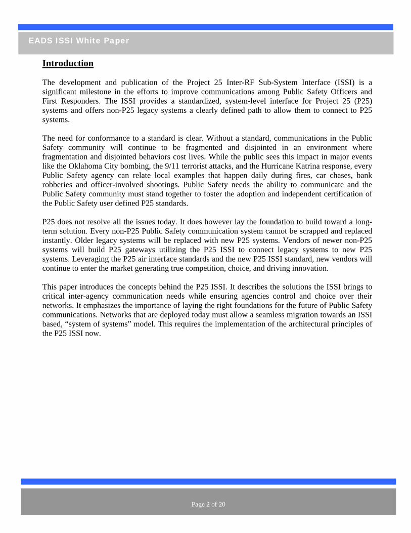
Introduction The development and publication of the Project 25 Inter-RF Sub-System Interface (ISSI) is a significant milestone in the efforts to improve communications among Public Safety Officers and First Responders. The ISSI provides a standardized, system-level interface for Project 25 (P25) systems and offers non-P25 legacy systems a clearly defined path to allow them to connect to P25 systems. The need for conformance to a standard is clear. Without a standard, communications in the Public Safety community will continue to be fragmented and disjointed in an environment where fragmentation and disjointed behaviors cost lives. While the public sees this impact in major events like the Oklahoma City bombing, the 9/11 terrorist attacks, and the Hurricane Katrina response, every Public Safety agency can relate local examples that happen daily during fires, car chases, bank robberies and officer-involved shootings. Public Safety needs the ability to communicate and the Public Safety community must stand together to foster the adoption and independent certification of the Public Safety user defined P25 standards. P25 does not resolve all the issues today. It does however lay the foundation to build toward a long-term solution. Every non-P25 Public Safety communication system cannot be scrapped and replaced instantly. Older legacy systems will be replaced with new P25 systems. Vendors of newer non-P25 systems will build P25 gateways utilizing the P25 ISSI to connect legacy systems to new P25 systems. Leveraging the P25 air interface standards and the new P25 ISSI standard, new vendors will continue to enter the market generating true competition, choice, and driving innovation. This paper introduces the concepts behind the P25 ISSI. It describes the solutions the ISSI brings to critical inter-agency communication needs while ensuring agencies control and choice over their networks. It emphasizes the importance of laying the right foundations for the future of Public Safety communications. Networks that are deployed today must allow a seamless migration towards an ISSI based, “system of systems” model. This requires the implementation of the architectural principles of the P25 ISSI now.
Page 2 of 20
EADS ISSI White Paper
ISSI concepts
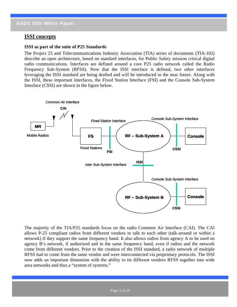
ISSI as part of the suite of P25 Standards The Project 25 and Telecommunications Industry Association (TIA) series of documents (TIA-102) describe an open architecture, based on standard interfaces, for Public Safety mission critical digital radio communications. Interfaces are defined around a core P25 radio network called the Radio Frequency Sub-System (RFSS). Now that the ISSI interface is defined, two other interfaces leveraging the ISSI standard are being drafted and will be introduced in the near future. Along with the ISSI, these important interfaces, the Fixed Station Interface (FSI) and the Console Sub-System Interface (CSSI) are shown in the figure below.
he majority of the TIA/P25 standards focus on the radio Common Air Interface (CAI). The CAI
area networks and thus a “system of systems.”
RF – Sub-System AFS
Fixed Stations
Common Air Interface
Mobile Radios
MRFixed Station Interface
RF – Sub-System B
Inter Sub-System Interface
Console
Console
Console Sub-System Interface
ISSI
FSI
CAI
CSSI
CSSI
Console Sub-System Interface
RF – Sub-System AFSFS
Fixed Stations
Common Air Interface
Mobile Radios
MRMRFixed Station Interface
RF – Sub-System B
Inter Sub-System Interface
ConsoleConsole
ConsoleConsole
Console Sub-System Interface
ISSI
FSI
CAI
CSSI
CSSI
Console Sub-System Interface
Tallows P-25 compliant radios from different vendors to talk to each other (talk-around or within a network) if they support the same frequency band. It also allows radios from agency A to be used on agency B’s network, if authorized and in the same frequency band, even if radios and the network come from different vendors. Prior to the creation of the ISSI standard, a radio network of multiple RFSS had to come from the same vendor and were interconnected via proprietary protocols. The ISSI now adds an important dimension with the ability to tie different vendors RFSS together into wide
Page 3 of 20
EADS ISSI White Paper
The introduction of the ISSI provides a defined standard to interconnect different networks,
gardless of frequency band or suppliers, together in such a way to allow roaming (mobility) of
ls as the ISSI, the P25 conventional Fixed Station Interface (FSI) has been efined to facilitate the integration of fixed stations and the RFSS. Similarly, the Console Sub-System
The ISSI includes the following features: roaming radios
ming radios (subscriber database management)
setup & teardown es to roaming radios
mong roaming and home-based radios The IS i ansport (using
eal-time Transport Protocol - RTP) and signaling (using Session Initiation Protocol – SIP).
together, e same way CDMA and GSM networks can be connected today based on their own standards.
dios perating under network A’s coverage and radios operating under network B’s coverage to
this network connectivity is the ISSI’s ability to support authentication and gistration of roaming radios. The ISSI allows radios from network A to operate under network B’s
between networks and when int operations from neighboring agencies become necessary.
resubscriber radios between networks. The ISSI supports dynamic, transparent and fully featured operations (e.g. PTT management) for individual and group calls across network boundaries. This is what the ISSI is about. Utilizing similar protocodInterface (CSSI) is designed to facilitate integration of consoles with the RFSS. The ISSI is being optimized to facilitate CSSI operations over the ISSI to ensure consoles connected to different RFSS can communicate with each other and for cross RFSS console support.
ISSI features and benefits
• Authentication of• Tracking current location of roa• Voice transport • P25 addressing scheme • Unit/Group Call • Home-based PTT servic• PTT communications management a
SI s an open IP-based interface relying on standard IP protocols for voice trR As a standard, the ISSI provides the unique capability to connect different vendor networks th By supporting individual and group calls as well as PTT across networks, the ISSI allows raocommunicate as if they were under a unique network. This applies independently of the frequency band used in network A and in network B, and whether network A’s coverage and network B’s coverage overlap or not. An additional feature of recoverage assuming the same frequency band. This includes the capability for network A to track and control its radios when they are under network B’s coverage and to dynamically include them in individual and group calls with no loss of features (including PTT and trunking). It also gives network B control of visiting radios based on inter-agency agreements. These capabilities become particularly useful to support border areas jo
Page 4 of 20
EADS ISSI White Paper
ISSI standardization history and future applications Early attempts in the 1990s by P25 and TIA to define the ISSI used a set of intersystem messages culled from the GSM Mobile Application Part (GSM MAP). However this did not address certain critical issues between systems such as registration of mobiles. Additional work explored the use of the Signaling System #7 (SS7) protocol, based on GSM MAP, or the ETSI TErrestrial Trunked Radio (TETRA) solution, based on QSIG, which both proved to be unfeasible. In early 2000, the TIA and Project 25 made a decision to explore the use of the emerging IETF Session Initiation Protocol (SIP) standard as a basis for a new all IP based ISSI. The TIA and Project 25 leadership felt that the amount of time and energy that would be required to develop the ISSI was best invested into an all IP based standard versus circuit switched technology. The TIA and Project 25 sub-committees debated the merits of SIP and analyzed SIP characteristics and latencies before making a decision to proceed with the development of a SIP based standard in 2002. A preliminary SIP standard was introduced in 2004 and a formal ballot was undertaken in 2005. Ballot comments and comments resolution extended until 2006, with the ISSI document approved for publication in June of 2006. The published document represents the ISSI for Trunked Voice Systems. Further work is in progress to address conventional operations, console operations, packet data, supplementary data, and Over-The-Air-Rekeying (OTAR) as supplements or addendums. EADS and Nortel provided critical early expertise in promoting the use of SIP as the call control mechanism (e.g. call setup and tear-down). This work led to the creation of an initial document for technical discussions. Other key contributors such as EF Johnson, Lucent, M/A-COM, NTIA/ITS (Institute for Telecommunications Sciences in Boulder, CO), and Motorola provided valuable input and comments on the critical in-call control and voice packet transport mechanisms using the Real-time Transport Protocol (RTP).
Page 5 of 20
EADS ISSI White Paper
ISSI solutions to inter-agency communication needs
AFECOM Interoperability Continuum
he ISSI implementation requires two fundamental operating elements to deliver the level of
e, and location
e planned and controlled such that traffic
teroperability scenarios described throughout this document make the assumption that Governance les between agencies have been agreed, that Standard Operating Procedures and Mechanisms have
een harmonized, and that Public Safety officers and Command & Control staff have been trained.
SThe ISSI solution is a key architectural and technical element to improve interoperability among agencies. However, as described in the SAFECOM Interoperability Continuum, technology alone cannot solve all issues related to interoperability. Usage, Training & Exercises, Standard Operating Procedures and Governance must be synchronized for the technology to be effective. Tinteroperability expected, as well as ensuring that control and choice over their network is maintained for each agency:
• First it needs cooperation between network operators in order to define the rules that will govern their inter-working. These rules include agreements for:
o numbering plans - in order to avoid duplication of numbers between two agencies o list of users, equipment, and groups allowed to roam, with associated authorized time
and location o list of services allowed for roaming users and groups, with associated authorized users,
timo Service Level Agreements (SLA) for those services that are provided to roamers.
• Second each agency must implement mechanisms to ensure the security of its own network (protection against unauthorized users, wrong use of services, wrong use of ISSI, …) as well as mechanisms to ensure that resources allocation arduring peak operations do not affect the capabilities of Public Safety users to communicate as needed. Some examples of this includes :
o Control and denial of un-authorized users at a visited RFSS o Prevent un-authorized foreign registration at the home RFSS o Ensure that services to native users will not be impacted by the intrusion of too many
foreign users in a visited RFSS
Inrub
Page 6 of 20
EADS ISSI White Paper
ISSI Architecture, Messages and Procedures
ISSI “Home oriented” Architecture The ISSI architecture is based on the concept of a “home” and a “serving” RFSS:
• The “home” RFSS represents the normal location and radio coverage area under which a particular talk group and/or individual operates.
• A “serving” RFSS represents a foreign location and radio coverage area to which a talk group
A g e ding subscri
ISSI Proce rThe core o ed on procedures defined to manage mobility, to control individual and group calls Mobility M
(or certain members of a talk group) and/or individual has roamed, and is not the native network to that user and/or talk group.
en ral principle of the ISSI is to be “home oriented”, which means that any decision regar
bers, groups and calls is taken at their home RFSS.
du es f the ISSI is bas, and to manage Push-To-Talk services.
anagement procedures The M
- -
A Subscrib U l be able to register and to affiliate w age of a serving RFSS (assuming t between th ” RFSS, the Group “home” RFSS and the “serving” RFSS.
g” FSS also has the responsibility to inform the “home” RFSS of its interest in that Group by
registering to that Group. The “home” RFSS of the SU and the “home” RFSS of the Group update their databases so when the need to connect a call to those roaming talk groups or individuals occurs, the networks know where the SU or the Group’s members are located. The Home RFSS and the Serving RFSS can be either in the same P25 System (Intra system) or in different P25 Systems (Inter system) within a Wide Area Communication Network (WACN).
obility Management procedures allow: A Subscriber Unit to access services outside of its home RFSS; A Group to be expanded outside of its home RFSS.
er nit (SU) moving outside its home RFSS radio coverage wilith the Group it is interested in when within the radio covercompatible radio frequencies) and allowed to operate according to a mutual agreemene owning agencies of the SU “home
The “serving” RFSS to which the SU has roamed has the responsibility to inform the “home” RFSS of the SU of the individual’s new location. If the SU wants to affiliate with a Group, the “servinR
Page 7 of 20
EADS ISSI White Paper
P25 SYSTEM 1
RFSS 1.1
RFSS 1.2
RFSS 2.1
RFSS 2.2
P25 SYSTEM 2
RFSS 2.3
ISSI over an IP Unicast Wide Area Network
Intra P25 System Roaming
Inter P25 Systems Roaming
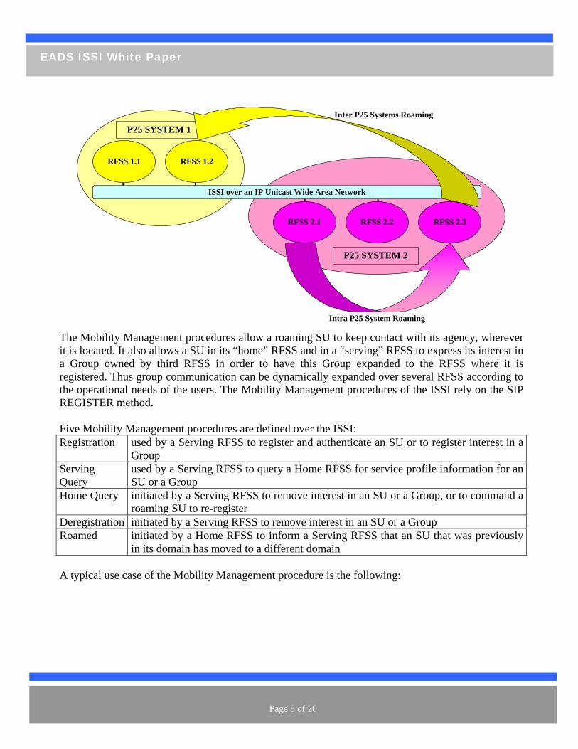
he Mobility Management procedures allow a roaming SU to keep contact with its agency, wherever
RFSS and in a “serving” RFSS to express its interest in a G u ed to the RFSS where it is reg r expanded over several RFSS according to
e operational needs of the users. The Mobility Management procedures of the ISSI rely on the SIP
Group
Tit is located. It also allows a SU in its “home”
ro p owned by third RFSS in order to have this Group expandiste ed. Thus group communication can be dynamically
thREGISTER method. Five Mobility Management procedures are defined over the ISSI: Registration used by a Serving RFSS to register and authenticate an SU or to register interest in a
Serving used by a Serving RFSS to query a Home RFSS for service profile information for an Query SU or a Group Home Query initiated by a Serving RFSS to remove interest in an SU or a Group, or to command a
roaming SU to re-register Deregistration initiated by a Serving RFSS to remove interest in an SU or a Group Roamed initiated by a Home RFSS to inform a Serving RFSS that an SU that was previously
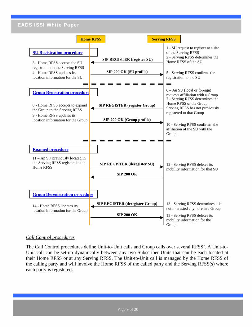
in its domain has moved to a different domain A typical use case of the Mobility Management procedure is the following:
Page 8 of 20
EADS ISSI White Paper
Home RFSS Serving RFSS
1 - SU request to register at a site of the Serving RFSS
SIP REGISTER (register SU) 3 - Home RFSS accepts the SU registration in the Serving RFSS
2 - Serving RFSS determines the Home RFSS of the SU
SIP 200 OK (SU profile) 5 - Serving RFSS confirms the registration to the SU
4 - Home RFSS updates its location information for the SU
6 – An SU (local or foreign) requests affiliation with a Group
SIP REGISTER (register Group) 8 - Home RFSS accepts to expand the Group to the Serving RFSS
7 - Serving RFSS determines the Home RFSS of the Group Serving RFSS has not previously registered to that Group
SIP 200 OK (Group profile) 10 - Serving RFSS confirms the affiliation of the SU with the Group
9 - Home RFSS updates its location information for the Group
SU Registration procedure
Group Registration procedure
Roamed procedure
11 – An SU previously located in the Serving RFSS registers in the Home RFSS
SIP REGISTER (deregister SU)
SIP 200 OK
12 - Serving RFSS deletes its mobility information for that SU
Group Deregistration procedure
SIP REGISTER (deregister Group) 13 - Serving RFSS determines it is not interested anymore in a Group
SIP 200 OK 15 - Serving RFSS deletes its mobility information for the Group
14 - Holocat
me RFSion inform
S updates its ation for the Group
trol pr Call Con ocedures The Call Control procedures define Unit-to-Unit calls and Group calls over several RFSS’. A Unit-to-
at can be each located at eir Home RFSS or at any Serving RFSS. The Unit-to-Unit call is managed by the Home RFSS of
the calling party and will involve the Home RFSS of the called party and the Serving RFSS(s) where each party is registered.
Unit call can be set-up dynamically between any two Subscriber Units thth
Page 9 of 20
EADS ISSI White Paper
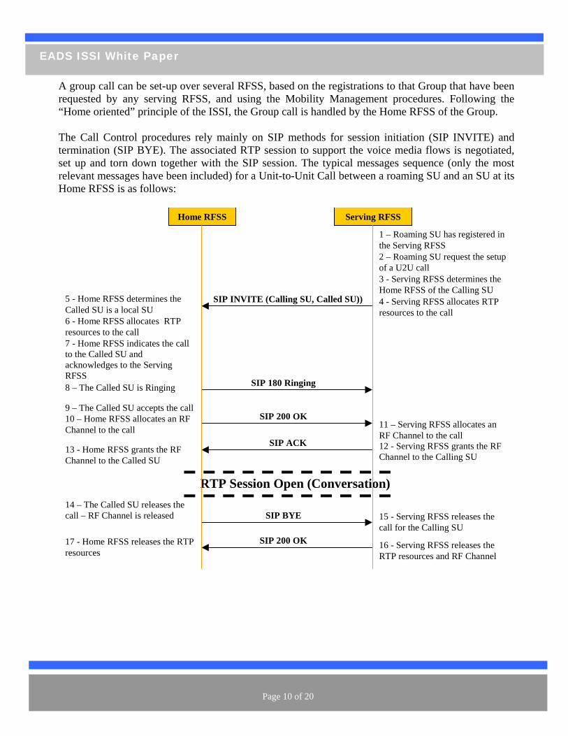
A group call can be set-up over several RFSS, based on the registrations to that Group that have been requested by any serving RFSS, and using the Mobility Management procedures. Following the “Home oriented” principle of the ISSI, the Group call is handled by the Home RFSS of the Group. The Call Control procedures rely mainly on SIP methods for session initiation (SIP INVITE) and termination (SIP BYE). The associated RTP session to support the voice media flows is negotiated, set up and torn down together with the SIP session. The typical messages sequence (only the most relevant messages have been included) for a Unit-to-Unit Call between a roaming SU and an SU at its Home RFSS is as follows: Home RFSS Serving RFSS
1 – Roaming SU has registered in the Serving RFSS
SIP INVITE (Calling SU, Called SU))5 - Home RFSS determines the Called SU is a local SU
2 – Roaming SU request the setup of a U2U call 3 - Serving RFSS determines the Home RFSS of the Calling SU
6 - Home RFSS allocates RTP resources to the call
4 - Serving RFSS allocates RTP resources to the call
7 - Home RFSS indicates the call to the Called SU and acknowledges to the Serving RFSS
SIP 180 Ringing
SIP 200 OK
SIP ACK
8 – The Called SU is Ringing
9 – The Called SU accepts the call
12 - Serving RFSS grants the RF Channel to the Calling SU
13 - Home RFSS grants the RF Channel to the Called SU
RTP Session Open (Conversation) 14 – The Called SU releases the call – RF Channel is released SIP BYE 15 - Serving RFSS releases the
call for the Calling SU SIP 200 OK 16 - Serving RFSS releases the
RTP resources and RF Channel resources 17 - Home RFSS releases the RTP
10 – Home RFSS allocates an RF Channel to the call 11 – Serving RFSS allocates an
RF Channel to the call
Page 10 of 20
EADS ISSI White Paper
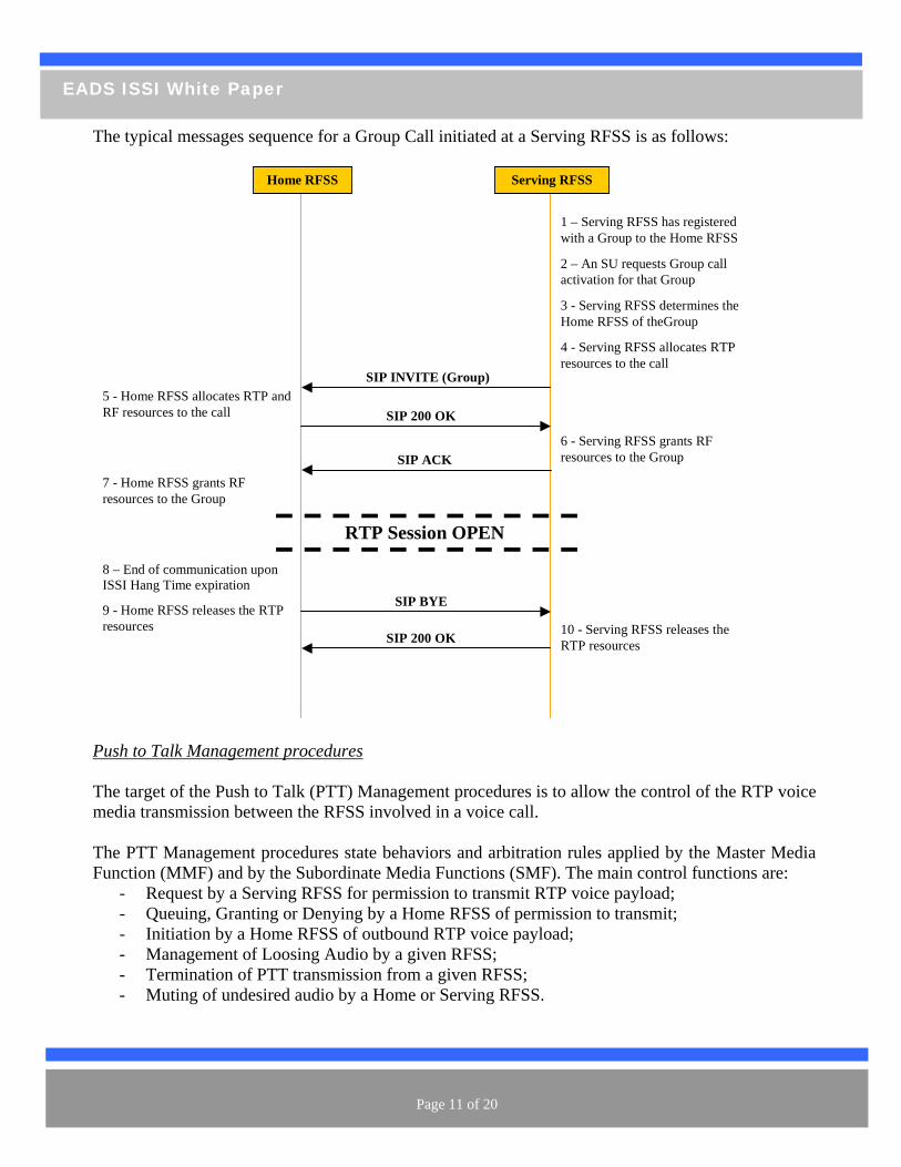
The typical messages sequence for a Group Call initiated at a Serving RFSS is as follows: Home RFSS Serving RFSS
1 – Serving RFSS has registered with a Group to the Home RFSS
2 – An SU requests Group call activation for that Group
SIP INVITE (Group)
3 - Serving RFSS determines the Home RFSS of theGroup
5 - Home RFSS allocates RTP and RF resources to the call
4 - Serving RFSS allocates RTP resources to the call
SIP 200 OK
SIP ACK 6 - Serving RFSS grants RF resources to the Group
7 - Home RFSS grants RF resources to the Group
RTP Session OPEN
SIP BYE
8 – End of communication upon ISSI Hang Time expiration
SIP 200 OK 10 - Serving RFSS releases the RTP resources
9 - Home RFSS releases the RTP resources
Push to Talk Management procedures The target of the Push to Talk (PTT) Management procedures is to allow the control of the RTP voice media transmission between the RFSS involved in a voice call. The PTT Management procedures state behaviors and arbitration rules applied by the Master Media Function (MMF) and by the Subordinate Media Functions (SMF). The main control functions are:
- Request by a Serving RFSS for permission to transmit RTP voice payload; - Queuing, Granting or Denying by a Home RFSS of permission to transmit; - Initiation by a Home RFSS of outbound RTP voice payload; - Management of Loosing Audio by a given RFSS; - Termination of PTT transmission from a given RFSS; - Muting of undesired audio by a Home or Serving RFSS.
Page 11 of 20
EADS ISSI White Paper
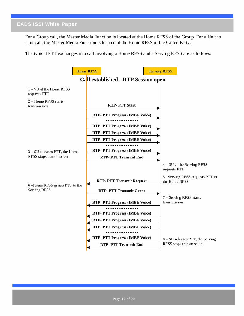
For a Group call, the Master Media Function is located at the Home RFSS of the Group. For a Unit to nit call, the Master Media Function is located at the Home RFSS of the Called Party.
The typical PTT exchanges in a call involving a Home RFSS and a Serving RFSS are as follows:
U
Home RFSS Serving RFSS
1 – SU at the Home RFSS requests PTT
RTP- PTT Start
Call established - RTP Session open
RTP- PTT Progress (IMBE Voice)
RTP- PTT Progress (IMBE Voice)
RTP- PTT Progress (IMBE Voice)
RTP- PTT Progress (IMBE Voice)
RTP- PTT Progress (IMBE Voice)
RTP- PTT Transmit End
4 – SU at the Serving RFSS requests PTT
2 – Home RFSS starts transmission
3 – SU releases PTT, the Home RFSS stops transmission
5 –Serving RFSS requests PTT to the Home RFSS RTP- PTT Transmit Request
RTP- PTT Transmit Grant 6 –Home RFSS grants PTT to the Serving RFSS
7 – Serving RFSS starts transmission RTP- PTT Progress (IMBE Voice)
RTP- PTT Progress (IMBE Voice)
RTP- PTT Progress (IMBE Voice)
RTP- PTT Progress (IMBE Voice)
RTP- PTT Progress (IMBE Voice) 8 – SU releasRFSS stops tr
es PTT, the ServingRTP- PTT Transmit End
ansmission
Page 12 of 20
EADS ISSI White Paper
Examples of ISSI use for agency interoperability
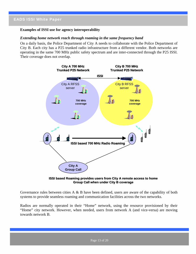
Extending home network reach through roaming in the same frequency band t of
ity B. Each city has a P25 trunked radio infrastructure from a different vendor. Both networks are perating in the same 700 MHz public safety spectrum and are inter-connected through the P25 ISSI.
Their coverage does not overlap.
Governance rules between cities A & B have been defined, users are aware of the capability of both systems to provide seamless roaming and communication facilities across the two networks.
adios are normally operated in their “Home” network, using the resource provisioned by their Home” city network. However, when needed, users from network A (and vice-versa) are moving wards network B.
On a daily basis, the Police Department of City A needs to collaborate with the Police DepartmenCo
City A 700 MHzTrunked P25 Network
TETRAPOL
City A RFSS server
City B 700 MHzTrunked P25 Network
City B RFSS server
ISSI
ISSI based 700 MHz Radio Roaming
ISSI based Roaming provides users from City A remote access to home Group Call when under City B coverage
City A Group Call
700 MHz coverage
700 MHz coverage
TETRAPOL
TETRAPOL
TETRAPOL
City A 700 MHzTrunked P25 Network
TETRAPOL
TETRAPOL
TETRAPOL
City A RFSS server
City B 700 MHzTrunked P25 Network
City B RFSS server
ISSI
ISSI based 700 MHz Radio Roaming
ISSI based Roaming provides users from City A remote access to home Group Call when under City B coverage
City A Group Call
700 MHz coverage
700 MHz coverage
TETRAPOL
TETRAPOL
TETRAPOL
TETRAPOL
TETRAPOL
TETRAPOL
TETRAPOL
TETRAPOL
TETRAPOL
R“to
Page 13 of 20
EADS ISSI White Paper
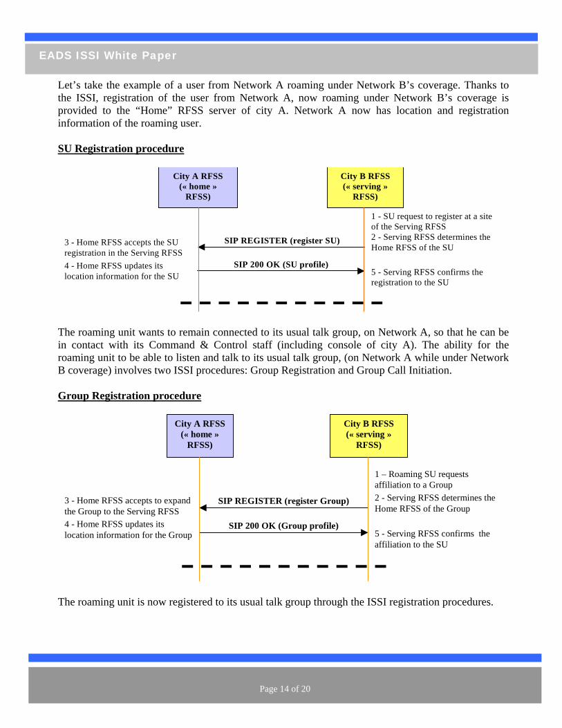
Let’s take the example of a user from Network A roaming under Network B’s coverage. Thanks to the ISSI, registration of the user from Network A, now roaming under Network B’s coverage is
tion and registration provided to the “Home” RFSS server of city A. Network A now has locainformation of the roaming user. SU Registration procedure City A RFSS
(« home » RFSS)
City B RFSS
er at a site
(« serving » RFSS)
1 - SU request to registof the Serving RFSS
SIP REGISTER (register SU) FSS accepts the SU n the Serving RFSS
2 - Serving RFSS determHome RFSS of the SU 3 - Home R
registration i
ines the
SIP 200 OK (SU profile) 5 - Serving RFSS confirmsregistration to the SU
FSS updates its rmation for the SU the
4 - Home Rlocation info
The roamin so that he can be in contact with its Co for the roam
g unit wants to remain connected to its usual talk group, on Network A, mmand & Control staff (including console of city A). The ability
ing unit to be able to listen and talk to its usual talk group, (on Network A while under NetworkB coverage) involves two ISSI procedures: Group Registration and Group Call Initiation.
Group Registration procedure
City A RFSS (« home »
RFSS)
City B RFSS (« serving »
RFSS)
1 – Roaming SU requests affiliation to a Group
SIP REGISTER (register Group) 3 - Home RFSS accepts to expand the Group to the Serving RFSS
2 - Serving RFSS determines the Home RFSS of the Group
SIP 200 OK (Group profile) 5 - Serving RFSS confirms the affiliation to the SU
4 - Home RFSS updates its location information for the Group
The roaming unit is now registered to its usual talk group through the ISSI registration procedures.
Page 14 of 20
EADS ISSI White Paper
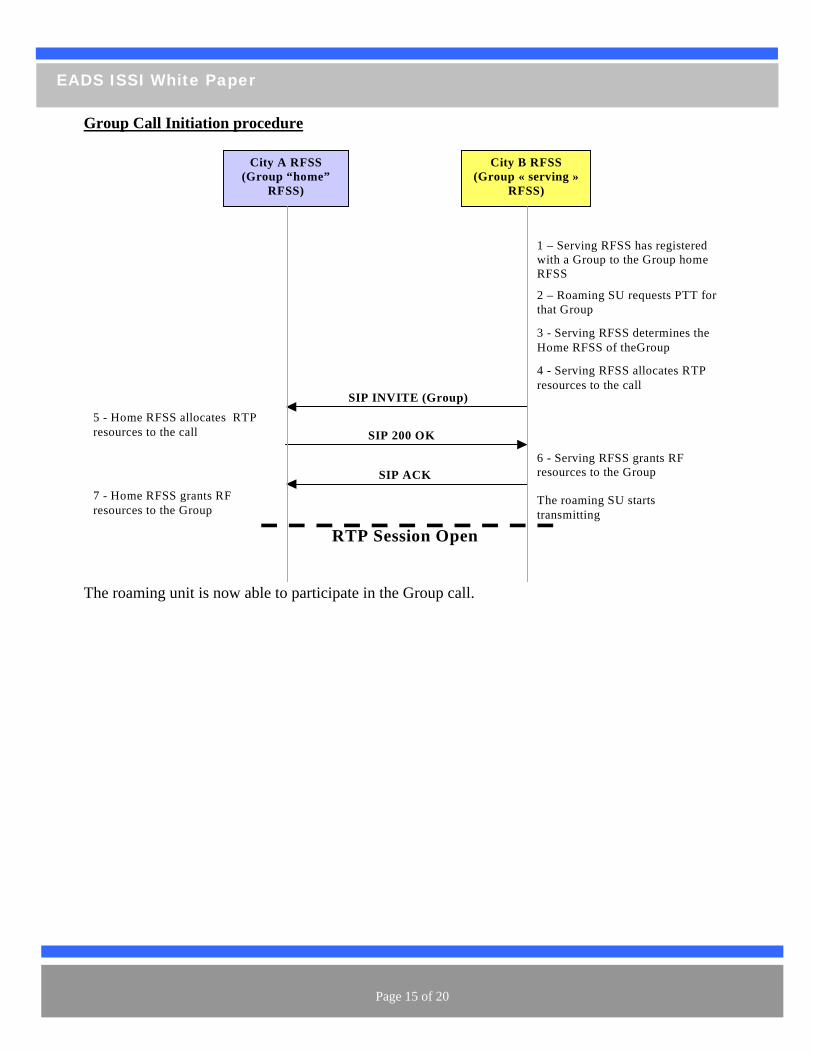
Group Call Initiation procedure City A RFSS
(Group “home” RFSS)
City B RFSS (Group « serving »
RFSS)
1 – Serving RFSS has registered with a Group to the Group home RFSS
SIP INVITE (Group)
2 – Roaming SU requests PTT for that Group
3 - Serving RFSS determines the Home RFSS of theGroup
5 - Home RFSS allocates RTP resources to the call
4 - Serving RFSS allocates RTP resources to the call
SIP 200 OK
SIP ACK 6 - Serving RFSS grants RF resources to the Group The roaming SU starts transmitting
7 - Home RFSS grants RF resources to the Group
RTP Session Open
articipate in the Group call.
The roaming unit is now able to p
Page 15 of 20
EADS ISSI White Paper
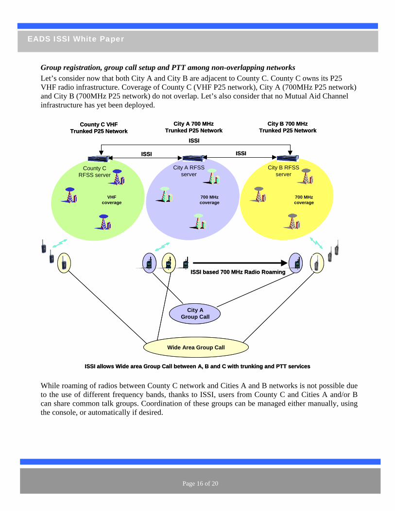
Group registration, group call setup and PTT among non-overlapping networks Let’s consider now that both City A and City B are adjacent to County C. County C owns its P25 VHF radio infrastructure. Coverage of County C (VHF P25 network), City A (700MHz P25 network) and City B (700MHz P25 network) do not overlap. Let’s also consider that no Mutual Aid Channel infrastructure has yet been deployed.
While roaming of radios between County C network and Cities A and B networks is not possible due to the use of different frequency bands, thanks to ISSI, users from County C and Cities A and/or B can share common talk groups. Coordination of these groups can be managed either manually, using the console, or automatically if desired.
City A 700 MHzTrunked P25 Network
TETRAPOL
City A RFSS server
City B 700 MHzTrunked P25 Network
City B RFSS server
ISSI
County C VHFTrunked P25 Network
County C RFSS server
ISSI
ISSI
ISSI allows Wide area Group Call between A, B and C with trunking and PTT services
Wide Area Group Call
City A Group Call
VHF coverage
700 MHz coverage
700 MHz coverage
ISSI based 700 MHz Radio Roaming
TETRAPOL
TETRAPOL
TETRAPOL
City A 700 MHzTrunked P25 Network
TETRAPOL
TETRAPOL
TETRAPOL
City A RFSS server
City B 700 MHzTrunked P25 Network
City B RFSS server
ISSI
County C VHFTrunked P25 Network
County C RFSS server
ISSI
ISSI
ISSI allows Wide area Group Call between A, B and C with trunking and PTT services
Wide Area Group Call
City A Group Call
VHF coverage
700 MHz coverage
700 MHz coverage
ISSI based 700 MHz Radio Roaming
TETRAPOL
TETRAPOL
TETRAPOL
TETRAPOL
TETRAPOL
TETRAPOL
TETRAPOL
TETRAPOL
TETRAPOL
Page 16 of 20
EADS ISSI White Paper
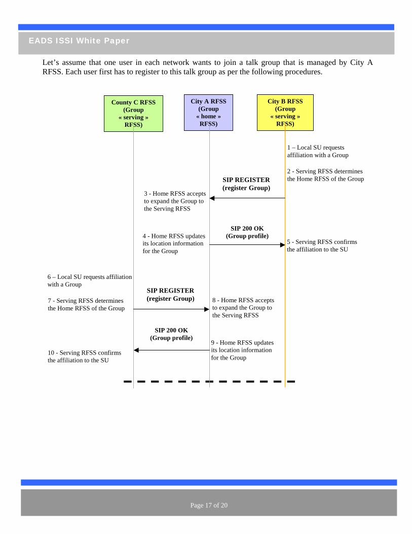
Let’s assume that one user in each network wants to join a talk group that is managed by City A es. RFSS. Each user first has to register to this talk group as per the following procedur
City A RFSS
(Group « home »
RFSS)
City B RFSS (Group
« serving » RFSS)
1 – Local SU requests affiliation with a Group
SIP REGISTER (register Group)
3 - Home RFSS accepts to expand the Group to the Serving RFSS
2 - Serving RFSS determines the Home RFSS of the Group
SIP 200 OK (Group profile)
5 - Serving RFSS confirms the affiliation to the SU
4 - Home RFSS updates its location information for the Group
County C RFSS (Group
« serving » RFSS)
6 – Local SU requests affiliation with a Group
7 - Serving RFSS determines the Home RFSS of the Group
8 - Home RFSS accepts to expand the Group to the Serving RFSS
9 - Home RFSS updates its location information for the Group
SIP 200 OK (Group profile)
SIP REGISTER (register Group)
10 - Serving RFSS confirms the affiliation to the SU
Page 17 of 20
EADS ISSI White Paper
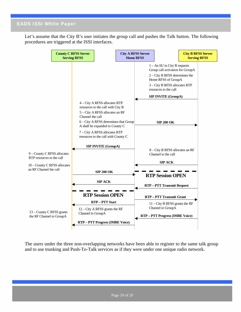
Let’s assume that the City B’s user initiates the group call and pushes the Talk button. The following procedures are triggered at the ISSI interfaces.
City B RFSS Server Serving RFSS
SIP INVITE (GroupA)
1 – An SU in City B requests Group call activation for GroupA
SIP 200 OK
2 – City B RFSS determines the Home RFSS of GroupA
4 – City A RFSS allocates RTP resources to the call with City B
3 – City B RFSS allocates RTP resources to the call
SIP 200 OK
SIP ACK
11 – City B RFSS grants the RF Channel to GroupA 12 – City A RFSS grants the RF
Channel to GroupA
RTP Session OPEN
5 – City A RFSS allocates an RF Channel the call
8 – City B RFSS allocates an RF Channel to the call
City A RFSS Server Home RFSS
County C RFSS Server Serving RFSS
6 – City A RFSS determines that Group A shall be expanded to County C
SIP INVITE (GroupA)
7 – City A RFSS allocates RTP resources to the call with County C
9 – County C RFSS allocates RTP resources to the call
10 – County C RFSS allocates an RF Channel the call
SIP ACK
13 – County C RFSS grants the RF Channel to GroupA
RTP Session OPEN
RTP – PTT Transmit Request
RTP – PTT Transmit Grant
RTP – PTT Progress (IMBE Voice)
RTP – PTT Start
RTP – PTT Progress (IMBE Voice)
The users under the three non-overlapping networks have been able to register to the same talk group and to use trunking and Push-To-Talk services as if they were under one unique radio network.
Page 18 of 20
EADS ISSI White Paper
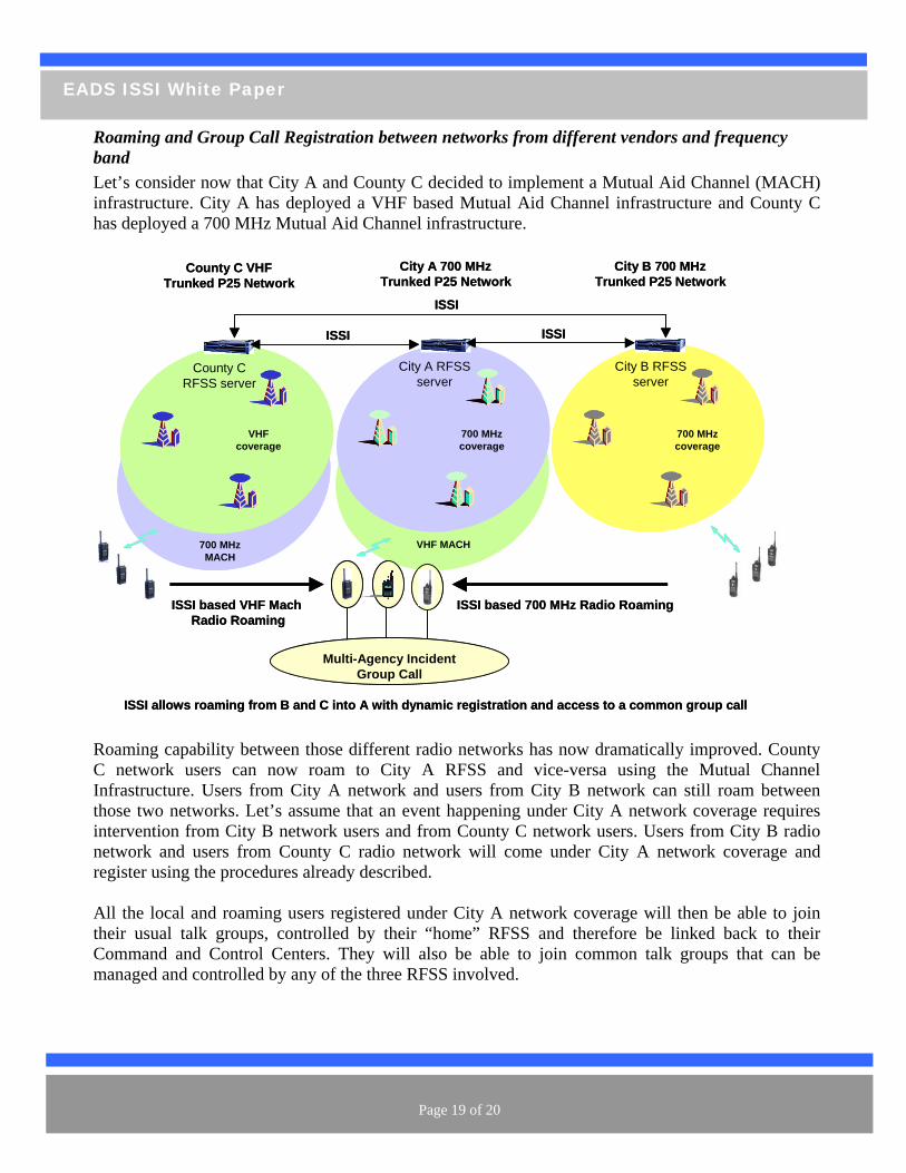
Roaming and Group Call Registration between networks from different vendors and frequency band Let’s consider now that City A and County C decided to implement a Mutual Aid Channel (MACH) infrastructure. City A has deployed a VHF based Mutual Aid Channel infrastructure and County C has deployed a 700 MHz Mutual Aid Channel infrastructure.
Roaming capability between those different radio networks has now dramatically improved. County C network users can now roam to City A RFSS and vice-versa using the Mutual Channel Infrastructure. Users from City A network and users from City B network can still roam between those two networks. Let’s assume that an event happening under City A network coverage requires intervention from City B network users and from County C network users. Users from City B radio network and users from County C radio network will come under City A network coverage and
gister using the procedures already described.
their Command and Control Centers. They will also be able to join common talk groups that can be managed and controlled by any of the three RFSS involved.
City A 700 MHzTrunked P25 Network
TETRAPOL
City A RFSS server
City B 700 MHzTrunked P25 Network
City B RFSS server
ISSI
County C VHFTrunked P25 Network
County C RFSS server
ISSI
ISSI
ISSI allows roaming from B and C into A with dynamic registration and access to a common group call
Multi-Agency Incident Group Call
700 MHzMACH
VHF MACH
VHF coverage
700 MHz coverage
700 MHz coverage
ISSI based 700 MHz Radio RoamingISSI based VHF Mach Radio Roaming
City A 700 MHzTrunked P25 Network
TETRAPOL
TETRAPOL
TETRAPOL
City A RFSS server
City B 700 MHzTrunked P25 Network
City B RFSS server
ISSI
County C VHFTrunked P25 Network
County C RFSS server
ISSI
ISSI
ISSI allows roaming from B and C into A with dynamic registration and access to a common group call
Multi-Agency Incident Group Call
700 MHzMACH
VHF MACH
VHF coverage
700 MHz coverage
700 MHz coverage
ISSI based 700 MHz Radio RoamingISSI based VHF Mach Radio Roaming
re All the local and roaming users registered under City A network coverage will then be able to join their usual talk groups, controlled by their “home” RFSS and therefore be linked back to
Page 19 of 20
EADS ISSI White Paper
Conclusions The examples in this paper are not intended to cover the full spectrum of the ISSI capability. However, they clearly demonstrate that the definition of the P25 ISSI interface provides the means for significant improvements in inter-agency interoperability. Roaming (mobility) of subscriber radios between networks and support for dynamic, transparent and fully featured (including PTT and
fety lution
e
e s
trunking), individual and group calls across network boundaries are the key benefits provided by the ISSI to the Public Safety community. The architectural concepts on which the ISSI relies will allow inter-working of Public Sanetworks while protecting the freedom for each agency to control and choose the network sothat best fits their specific environment. While a complete migration to such architecture will taktime, the sooner ISSI architectural concepts are implemented in Public Safety Radio Networks, the quicker this migration will occur and bring its benefits to the Public Safety community. Wencourage that all new system purchases should require the ISSI interface and that existing systemexplore the implementation of an ISSI gateway for connectivity to new systems.
Page 20 of 20