Embed Size (px)
Citation preview
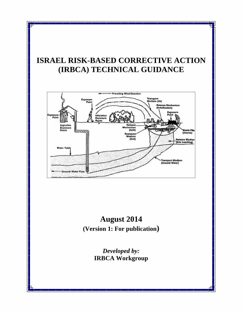
ISRAEL RISK-BASED CORRECTIVE ACTION (IRBCA) TECHNICAL GUIDANCE
August 2014 (Version 1: For publication)
Developed by: IRBCA Workgroup
IRBCA Technical Guidance, TOC RAM Group (050405) November 2013
i
TABLE OF CONTENTS Page TABLE OF CONTENTS i LIST OF TABLES v LIST OF FIGURES v LIST OF APPENDICES v ABBREVIATIONS vii ACKNOWLEDGEMENTS ix 1.0 BACKGROUND AND OBJECTIVES 1-1
1.1 INTRODUCTION 1-1 1.2 APPLICABILITY 1-1 1.3 LONG-TERM STEWARDSHIP 1-3
2.0 OVERVIEW OF IRBCA PROCESS 2-1
2.1 INTRODUCTION 2-1 2.2 ISRAEL RISK-BASED CORRECTIVE ACTION PROCESS 2-2
2.2.1 Site Discovery 2-2 2.2.2 Determination and Abatement of Imminent Threat(s) 2-2 2.2.3 Site Characterization and Comparison with Default Very Strict
Levels 2-3 2.2.4 Ecological Risk Assessment 2-4 2.2.5 Development and Validation of Conceptual Site Model (CSM) 2-5 2.2.6 Tier 1 Risk Assessment 2-6 2.2.7 Tier 2 Risk Assessment 2-7 2.2.8 Tier 3 Risk Assessment 2-7 2.2.9 Development and Approval of Risk Management Plan (RMP) 2-7 2.2.10 Implementation and Completion of Risk Management Plan 2-8 2.2.11 Long-Term Stewardship 2-9 2.3 TARGET LEVELS WITHIN THE IRBCA PROCESS 2-10 2.4 RATIONALE AND CHARACTERISTICS OF TIERED APPROACH 2-11 2.5 DOCUMENTATION OF THE IRBCA PROCESS 2-11 3.0 PROCESS OF SITE DISCOVERY 3-1
4.0 MANAGEMENT OF IMMINENT THREAT 4-1
4.1 INDENTIFICATION OF IMMINENT THREAT 4-1 4.2 NOTIFICATION OF IMMINENT THREAT 4-1 4.3 EMERGENCY RESPONSE ACTIONS 4-2
4.3.1 Actions to Mitigate Imminent Threats 4-2 4.3.2 Actions to Prevent Further Deterioration 4-2
IRBCA Technical Guidance, TOC RAM Group (050405) November 2013
ii
4.3.3 Actions to Prevent Long-Term Impacts 4-2 4.4 DOCUMENTATION OF RESPONSE ACTIVITIES 4-2
5.0 INTIAL SITE CHARACTERIZATION AND COMPARISON WITH VSLs 5-1 5.1 OBJECTIVES OF INITIAL SITE CHARACTERIZATION 5-1 5.2 SITE DESCRIPTION 5-1 5.3 COLLECTION OF DATA 5-1 5.4 ECOLOGICAL RISK ASSESSMENT 5-2 5.5 COMPARISON WITH ECOLOGICAL VSLs and WQCs 5-2 5.6 EVALUATION OF THE NEXT COURSE OF ACTION 5-3 5.6.1 Consideration of Concentrations Reported below the Reporting
Limits 5-3 5.7 INTIAL SITE CHARACTERIZATION REPORT 5-4 6.0 DEVELOPMENT AND VALIDATION OF CSM 6-1 6.1 INTRODUCTION 6-1 6.2 COMPONENTS OF CSM 6-1 6.3 SITE INFORMATION 6-3 6.3.1 Site Location Map 6-4 6.3.2 Site Map 6-4 6.3.3 Ground Surface Conditions 6-4 6.3.4 Location of Utilities On and Adjacent to the Site 6-5 6.3.5 Surface Water Bodies 6-6 6.3.6 On-site and Adjacent Off-site Groundwater Use 6-6 6.3.7 Local Hydrology and Aquifer Characteristics 6-6 6.3.8 Sea Water 6-7 6.4 DESCRIPTION AND MAGNITUDE OF SPILL RELEASE 6-7 6.4.1 History of Activities at the Site 6-8 6.4.2 Location and Date of Spill or Release 6-8 6.4.3 Quantity of Spill or Release 6-9 6.4.4 Consideration of Petroleum Products 6-10 6.4.4.1 Very Strict Levels 6-10 6.4.4.2 Chemicals of Concern 6-10 6.4.4.3 Tier 1 Target Levels: Residential, Commercial, and Protection of Groundwater 6-11 6.4.4.4 Tier 2 Target Levels: Residential, Commercial, and Protection of Groundwater 6-12 6.4.4.5 Nuisance Conditions 6-12 6.5 ADJACENT LAND USE, ACTIVITY AND USE LIMITATIONS, AND RECEPTOR INFORMATION 6-13 6.5.1 Current Land Use 6-13 6.5.2 Future Land Use 6-14
IRBCA Technical Guidance, TOC RAM Group (050405) November 2013
iii
6.5.3 Off-site Groundwater Use 6-14 6.5.4 Ecological Receptor Survey 6-14 6.6 ANALYSIS OF CURRENT AND FUTURE GROUNDWATER USE 6-15 6.6.1 Current Groundwater Use 6-15 6.7 VADOSE ZONE SOIL CHARACTERISTICS 6-16 6.7.1 Dry Bulk Density 6-17 6.7.2 Total Porosity 6-17 6.7.3 Volumetric Water Content and/Moisture Content 6-18 6.7.4 Fractional Organic Carbon Content in Soil 6-19 6.7.5 Thickness of Vadose Zone and Depth to Groundwater 6-19 6.7.6 Thickness of Capillary Fringe 6-20 6.8 CHARACTERISTICS OF SATURATED ZONE 6-21 6.8.1 Hydraulic Conductivity 6-22 6.8.2 Horizontal and Vertical Hydraulic Gradients 6-22 6.8.3 Saturated Zone Soil Characteristics 6-23 6.8.4 Indicators of Biodegradation in Groundwater 6-23 6.8.5 Occurrence and Rate of Natural Attenuation/Biodegradation 6-23 6.9 SURFACEWATER BODY CHARACTERISTICS 6-26 6.10 DELINEATION OF IMPACTS 6-26 6.10.1 Delineation of Impacts in Soil and Groundwater 6-26 6.10.2 Delineation of Impacts in Other Media 6-28 6.11 ECOLOGICAL RISK ASSESSMENT 6-29 6.11.1 Level 1 Ecological Risk Assessment 6-29 6.11.2 Level 2 Ecological Risk Assessment 6-30 6.11.3 Level 3 Ecological Risk Assessment 6-31 6.12 CHEMICALS OF CONCERN IN SOIL 6-32 6.12.1 Soil Source Data 6-33 6.12.2 Logging of Soil Boreholes 6-34 6.12.3 Surficial Soil Sampling 6-34 6.12.4 Subsurface Soil Sampling 6-35 6.13 CHEMICALS OF CONCERN IN GROUNDWATER 6-37 6.13.1 Delineation of Groundwater Impacts 6-37 6.13.2 Determination of Plume Stability 6-37 6.13.3 Groundwater Sampling 6-38 6.14 CHEMICALS OF CONCERN IN SOIL GAS 6-38 6.15 CHEMICALS OF CONCERN IN SEDIMENTS, SURFACE WATERS
INCLUDING MARINE WATER 6-39 6.15.1 Estimating POD Concentrations 6-39 6.15.2 Sediments 6-40 6.15.3 Non-Aqueous Phase Liquids (NAPL) 6-40 6.16 COLLECTION AND ANALYSIS OF ENVIRONMENTAL 6-41 SAMPLES 6.17 INFORMATION SOURCES FOR DATA COLLECTION 6-41
IRBCA Technical Guidance, TOC RAM Group (050405) November 2013
iv
7.0 TIER 1 RISK ASSESSMENT 7-1 7.1 STEP 1: COMPILE DATA AND IDENTIFICATION OF DATA GAPS 7-1 7.2 STEP 2: DEVELOP EXPOSURE MODEL 7-2 7.3 STEP 3: COLLECTION DATA TO FILL DATA GAPS, IF
NECESSARY 7-3 7.4 STEP 4: CALCULATION REPRESENTATIVE CONCENTRATIONS 7-3 7.5 STEP 5: SELECTION OF RELEVANT TIER 1 RBTLs AND
COMPARISON WITH REPRESENTATIVE CONCENTRATIONS 7-4 7.6 STEP 6: DETERMINATIO OF THE NEXT COURSE OF ACTION AND
DOCUMENTION OF TIER 1 ASSESSMENT AND RECOMMENDATIONS 7-6
8.0 TIER 2 RISK ASSESSMENT 8-1 8.1 STEP 1: DEVELOPMENT OF A WORK PLAN 8-1 8.2 STEP 2: CALCULATION OF TIER 2 RISKS 8-2 8.2.1 Groundwater Resource Protection Evaluation 8-3 8.2.2 Surface Water Evaluation 8-3 8.3 STEP 3: COMPARISON OF TIER 2 RISKS WITH ACCEPTABLE
RISK LEVELS 8-3 8.4 STEP 4: RECOMMENDATION FOR THE NEXT COURSE OF ACTION 8-5 8.5 STEP 5: DOCUMENTION OF THE TIER 2 RISK ASSESSMENT AND RECOMMENDATIONS 8-8 9.0 TIER 3 RISK ASSESSMENT 9-1 9.1 STEP 1: DEVELOPMENT OF A TIER 3 WORK PLAN 9-1 9.2 STEP 2: COLLECTION OF ADDITIONAL DATA, IF NECESSARY 9-3 9.3 STEP 3: CALCULATION OF TIER 3 RISKS 9-3 9.4 STEP 4: COMPARISON OF CALCULATED RISK WITH
ACCEPTABLE RISK LEVELS AND IF NECESSARY, DEVELOPMENT OF CLEAN-UP LEVELS 9-3
9.5 STEP 5: DETERMINATION OF THE NEXT COURSE OF ACTION 9-4 9.5.1 Surface Water Evaluation 9-6 9.5.2 Evaluation of Other Pathways 9-6 9.6 STEP 6: DOCUMENTION OF TIER 3 RISK ASSESSMENT AND
RECOMMENDATIONS 9-7 10.0 RISK MANAGEMENT PLAN 10-1 10.1 NEED FOR A RISK MANAGEMENT PLAN 10-1 10.2 CONTENTS OF RISK MANAGEMENT PLAN 10-2

IRBCA Technical Guidance, TOC RAM Group (050405) November 2013
v
10.3 COMPLETION OR RISK MANAGEMENT ACTIVITIES 10-4 10.4 NO FURTHER ACTION PROCEDURE 10-4 11.0 LONG-TERM STEWARDSHIP FOR RISK-BASED REMEDIAL ACTION SITES 11-1 11.1 BACKGROUND 11-1 11.2 LONG-TERM STEWARDSHIP PRINCIPLES 11-2 11.3 ACTIVITY AND USE LIMITATIONS 11-4 11.3.1 Engineered Controls 11-4 11.3.2 Well Location and Construction Restrictions 11-5 11.4 NFA LETTERS: ISSUANCE AND VOIDANCE 11-5 11.5 INFORMATION AND TRACKING 11-7 12.0 REFERENCES 12-1
LIST OF TABLES
Table 2-1 Comparison of Different Tiered Evaluations Table 5-1(a) Very Strict Levels (VSLs) for Soil Table 5-1(b) Very Strict Levels (VSLs) for Surface and Marine Waters Table 6-1 Chemical Constituents for Several Petroleum Products Table 6-2 Chemicals of Concern for Petroleum Products Table 6-3(a) Ecological Risk Assessment Screening Checklist A Table 6-3(b) Ecological Risk Assessment Screening Checklist B Table 6-4(a) Ecological Very Strict Screening Levels (Eco-VSLs) for Soil Table 6-4(b) Ecological Very Strict Screening Levels (Eco-VSLs) for Sediments Table 7-1(a) Example Table to Document the Exposure Model for Resident Table 7-1(b) Example Table to Document the Exposure Model for Commercial
Worker Table 7-1(c) Example Table to Document the Exposure Model for Construction
Worker Table 7-2(a) Tier 1 Risk-Based Target Levels for Residential Land Use Table 7-2(b) Tier 1 Risk-Based Target Levels for Commercial/Industrial Land Use Table 7-2(c) Tier 1 Risk-Based Target Levels for Construction Worker Table 7-2(d) Tier 1 Risk-Based Target Levels Protective of Groundwater for Soil and
Groundwater Without Biodegradation Table 7-2(e) Tier 1 Dilution Attenuation Factor for saturated zone Groundwater Table 7-2(f) Tier 1 Risk-Based Target Levels Protective of Freshwater for Soil and
Groundwater without Biodegradation
IRBCA Technical Guidance, TOC RAM Group (050405) November 2013
vi
LIST OF FIGURES Figure 2-1 Key Activities Conducted Under the IRBCA Process Figure 2-2 Israel Risk-Based Corrective Action Flow Chart Figure 6-1 Hydrogeological Regimes Figure 6-2 An Example of a Land Use Map
LIST OF APPENDICES Appendix A Selection of COCs for IRBCA Evaluation Appendix B (Intentionally left blank) Appendix C Parameters to be Changed for Tier 2 Risk Assessment Appendix D Representative Concentrations Appendix E Development of Risk-Based Target Levels Appendix F Definitions
IRBCA Technical Guidance, TOC RAM Group (050405) November 2013
vii
ABBREVIATIONS ALM Adult Lead Methodology AQL Aquatic Life ASTM American Society for Testing and Materials ATSDR Agency for Toxic Substances and Disease Registry AUL Activity and Use Limitation AWQC Ambient Water Quality Criteria BAT Best Available Technology BCF Bioconcentration Factor bgs Below Ground Surface CalEPA California Environmental Protection Agency CHHSL California Human Health Screening Level CLF Cool Water Fishery COCs Chemicals of Concern CSM Conceptual Site Model CTL Cleanup Target Levels DAF Dilution Attenuation Factor DCE cis-1,2-Dichloroethene DNAPL Dense Non-Aqueous Phase Liquid DOE Department of Energy DWS Drinking Water Supply EM Exposure Model ERA Ecological Risk Assessment ESA Environmental Site Assessment ESL Environmental Screening Levels ET Ecotox Thresholds EU Exposure Unit HDPE High Density Polyethylene HEAST Health Effects Assessment Summary Tables HH Human Health HHRA Human Health Risk Assessment HI Hazard Index HQ Hazard Quotient IDWS Israeli Drinking Water Standard IELCR Individual Excess Lifetime Cancer Risk IEUBK Integrated Exposure uptake Biokinetic IND Industrial IRBCA Israel Risk-Based Corrective Action IRIS Integrated Risk Information System IRR Irrigation ISC Initial Site Characterization ITRC Interstate Technology & Regulatory Council IWA Israel Water Authority LNAPL Light Non-Aqueous Phase Liquid LTS Long-Term Stewardship
IRBCA Technical Guidance, TOC RAM Group (050405) November 2013
viii
LWW Livestock & Wildlife Watering m Meters MDNR Missouri Department of Natural Resources MIP Membrane Interface Probe MNA Monitored Natural Attenuation MoEP Ministry of Environmental Protection MRBCA Missouri Risk-Based Corrective Action MRL Minimal Risk Level NAPL Non-Aqueous Phase Liquid NCEA National Center for Environmental Assessment NFA No Further Action NOAA National Oceanic and Atmospheric Administration ORNL Oak Ridge National Laboratory PCB Polychlorinated Biphenyls PCE Tetrachloroethylene PID Photoionization Detector POD Point of Demonstration POE Point of Exposure PVC Poly Vinyl Chloride QAPP Quality Assurance Project Plan QA/QC Quality Assurance/Quality Control RA Risk Assessment RAGS Risk Assessment Guidance for Superfund RBCA Risk Based Corrective Action RBTL Risk-Based Target Level RC Representative Concentration RCRA Resource Conservation and Recovery Act RM Risk Management RMP Risk Management Plan RP Responsible Party SC Site Characterization SF Slope Factor SOP Standard Operating Procedure SSL Soil Screening Levels SSTL Site-Specific Target Level SWCTL Surface Water Cleanup Target Level TCE Trichlorocehtylene TIC Tentatively Identified Compound UCL Upper Confidence Limit USEPA United States Environmental Protection Agency VOC Volatile Organic Compound VSL Very Strict Level WBR Whole Body Recreation Workgroup IRBCA Workgroup WQC Water Quality Criteria XRF X-Ray Fluorescence
IRBCA Technical Guidance, TOC RAM Group (050405) November 2013
ix
ACKNOWLEDGEMENTS
This document reflects the work of the IRBCA Workgroup in which representatives of the following organizations were involved:
The Israeli Institute of Energy and Environment Ministry of Environmental Protection Israel's Water Authority Ministry of Health Israel Electric Corporation Manufacture's Association of Israel Adam Teva V'din - Israel Union for Environmental Defense
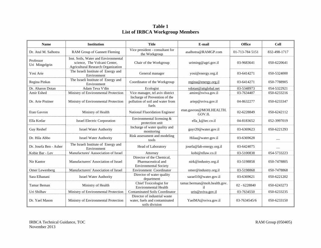
The attached Table 1 lists the members of the IRBCA Workgroup. The activities leading to the composition of this document were sponsored and organized by the Israeli Institute of Energy and Environment. Members of the IRBCA Work group thank the RAM Group of Gannett Fleming, Inc. and in particular Dr. Atul M. Salhotra for skillfully guiding the activities of the committee and providing valuable education and training.
IRBCA Technical Guidance, TOC RAM Group (050405) November 2013
Table 1 List of IRBCA Workgroup Members
Name Institution Title E-mail Office Cell
Dr. Atul M. Salhotra RAM Group of Gannett Fleming Vice president - consultant for
the Workgroup [email protected] 01-713-784 5151 832-498-1717
Professor Uri Mingelgrin
Inst. Soils, Water and Environmental science, The Volcani Center,
Agricultural Research Organization Chair of the Workgroup [email protected] 03-9683641 050-6220641
Yosi Arie The Israeli Institute of Energy and
Environment General manager [email protected] 03-6414271 050-5324000
Regina Pinkas The Israeli Institute of Energy and
Environment Coordinator of the Workgroup [email protected] 03-6414271 050-7788905
Dr. Aharon Dotan Adam Teva V'din Ecologist [email protected] 03-5348973 054-5322921 Amir Eshed Ministry of Environmental Protection Vice manager, tel aviv district [email protected] 03-7634407 050-6233216
Dr. Arie Pistiner Ministry of Environmental Protection Incharge of Prevention of the
pollution of soil and water from fuels
[email protected] 04-8632277 050-6233347
Etan Gavron Ministry of Health National Fluoridation Engineer [email protected].
GOV.IL 02-6228849 050-6242112
Ella Kotlar Israel Electric Corporation Environmental licensing &
protection unit [email protected] 04-8183652 052-3997019
Guy Reshef Israel Water Authority Incharge of water quality and
monitoring [email protected] 03-6369623 050-6221293
Dr. Hila Abbo Israel Water Authority Risk assessment and modeling
tools [email protected] 03-6369628 __
Dr. Josefa Ben - Asher The Israeli Institute of Energy and
Environment Head of Laboratory [email protected] 03-6424075 __
Kobie Bar - Lev Manufactures' Aassociation of Israel Attorney [email protected] 03-5100838 054-5733223
Nir Kantor Manufacturers' Association of Israel Director of the Chemical,
Pharmaceutical and Environmental Society
[email protected] 03-5198858 050-7478805
Omer Lewenberg Manufacturers' Association of Israel Environment Coordinator [email protected] 03-5198868 050-7478868
Sara Elhanani Israel Water Authority Director of water quality
department [email protected] 03-6369621 050-6221202
Tamar Beman Ministry of Health Chief Toxicologist for Environmental Health
02 - 6228840 050-6243273
Uri Shilhav Ministry of Environmental Protection Contaminated Soils Coordinator [email protected] 03-7634550 050-6233235
Dr. Yael Mason Ministry of Environmental Protection Director of industrial waste
water, fuels and contaminated soils division
[email protected] 03-7634545/6 050-6233150
IRBCA Technical Guidance, Section 1.0 RAM Group (050405)
November 2013
Page 1-1
1.0
BACKGROUND AND OBJECTIVES
1.1 INTRODUCTION
The motivation to develop the Israel Risk-Based Corrective Action (IRBCA) process is to
provide a technically defensible, consistent and objective decision making framework for
the management of remedial response of contaminated sites. Correct application of this
process will ensure the protection of human health and the environment under current and
reasonable future land use.
This framework can streamline the process of site cleanup and closure and provide (i) a
scientifically defensible and consistent process to make decisions related to site
characterization, risk assessment, and risk management necessary for site cleanup; and
(ii) a reliable process for property owners and developers and other entities that are
involved in the evaluation and management of contaminated sites. Although the
framework promotes cost-effective site management activities, it does not allow cost
considerations to compromise human health or the environment.
This technical guidance document describes the key elements and methodologies of the
IRBCA process. It is based on the risk-based corrective action (RBCA) standards
developed by the American Society for Testing and Materials (ASTM) E1739-95 (1995a)
and E2081-00 (2000a). However, it has been modified to account for Israel specific
conditions. The document also takes into account the guidance provided by United States
of America Environmental Protection Agency (USEPA) in the development of Regional
Screening Levels (RSLs) and several state documents including but not limited to
Massachusetts, California and Hawaii.
This document has been developed by a competent and diverse stakeholder group, called
the IRBCA Workgroup (Workgroup), listed in the acknowledgement section. The
individuals in the Workgroup represented the authorities, government bodies, industries,
and non-government organizations (NGOs). The Workgroup was supported by Dr. Atul
Salhotra and his colleagues at the Houston, Texas office of Risk Assessment &
Management (RAM) Group of Gannett Fleming, Inc., USA.
1.2 APPLICABILITY
This guidance applies to contaminated or potentially contaminated sites. It provides the
framework to conduct site-specific characterization; calculate risk-based target levels
(RBTLs) protective of human health and the environment; and implement appropriate
remediation and risk management activities. The guidance must facilitate the restoration
of contaminated sites (and sites suspected to be contaminated) for safe reuse for current
and future site uses and receptors. The various media-specific concentrations described
here are not to be interpreted as “a license to pollute the environment to these levels”.
Ongoing business activities must be conducted in a manner that minimizes the release of
chemicals to the environment, cleanup of contaminated sites, ensures sustainable
IRBCA Technical Guidance, Section 1.0 RAM Group (050405)
November 2013
Page 1-2
development, and is protective of human health and the environment for current and
reasonable future conditions.
IRBCA is applicable to all media and the entire contaminated site. Application to selective
media (e.g., soil or groundwater only) is not allowed unless it can be demonstrated to the
authorities that the medium is completely independent of the other media.
This technical guidance has been written for environmental professionals with
background in site characterization, risk assessment, and risk management (including
remediation). Because these practices and the overall process are relatively new to Israel,
it is described at length in this document. Prior experience or training is necessary for any
individual risk assessor to correctly implement the IRBCA process and, by that, ensure
efficient and safe site management.
Below are the requirements of the team performing IRBCA evaluations. At least one
team member must have a B.Sc. or higher degree in natural sciences, civil or
environmental engineering, with specialization in hydrology, geology, soil and water
science, environmental chemistry and statistics. Team members must have expertise or be
trained in field work regarding soil, soil gas, and water sampling methods. For some sites
a toxicologist must be included in the team. To be allowed to perform risk assessment, an
individual must have successfully completed a course in risk assessment based on the
RBCA methodology or on the IRBCA protocol (August 2014 version) and approved by
the MoEP and the IWA. Ecological risk assessment (ERA) can be conducted by a trained
ecologist or a professionals approved by the MoEP. When the risk assessment involves
groundwater or Tier 2 or 3 assessments, one of the team members must be versed in the
application of fate and transport models to the unsaturated and saturated zones.
Along with the above academic credentials, a team performing risk assessment must
demonstrate experience in human health risk assessment (HHRA) and ERA. The team
must have completed prior assessments for at least 3 sites using the IRBCA methodology
and its associated software and performed in cooperation with an international firm
approved by the MoEP and the IWA and with experience of over 5 years in conducting
risk assessments using the RBCA methodology. These risk assessments must cover a
broad range of chemicals of concern, impacted media, exposure pathways, land use, size
of the site, and tier level and include HHRA and ERA. Yet, at least one of the previous
sites handled by the team must be similar in nature and involve exposure pathways
similar to the site for which a risk assessment is required. If requested, members of the
team should submit to the authorities a verifiable list of sites, clients, and projects details.
The MoEP and IWA reserve the right to require, any time, the addition to the team
performing the risk assessment an expert with the appropriate international experience.
The following additional factors must be considered:
1. The RP must decide whether he wants to conduct a risk assessment at an early
stage so he can design the sampling plans to follow the IRBCA methodology and
the authorities risk oriented site characterization instructions.
IRBCA Technical Guidance, Section 1.0 RAM Group (050405)
November 2013
Page 1-3
2. The Responsible Party (RP) must notify the authorities about his decision to
conduct risk assessment instead of cleanup to Very Strict Levels/Israel Drinking
Water Standards (VSLs/IDWS).
3. After the acknowledgment of the authorities that they have received this
notification, the RP will submit a detailed and thorough work plan which will
include, at a minimum, (i) the preliminary site conceptual model, (ii) evaluation
of existing data, (iii) data gap analysis, (iv) proposed method to be used to fill the
data gaps (i.e. additional site characterization), (iv) models and parameters that
will be used to perform the risk evaluation.
4. The RP will submit a revised work plan to address all comments received from
the authorities. Upon approval of the work plan by the authorities, activities must
be conducted to fill the data gaps. The RP will submit a risk-oriented site
characterization report to fill the data gaps and request the relevant authorities’
approval.
5. After completing the risk-oriented site characterization, the RP will submit to the
relevant authorities a revised risk assessment work plan which will include, at a
minimum, (i) an updated/revised site conceptual model, (ii) compilation and
evaluation of all data and presentation of representative concentrations and
rationale, (iii) updated models and parameters and assumptions that will be used
to perform the risk evaluation. After the authorities’ approval, the RP will then
proceed with performing the risk assessment.
Upon completion of the risk assessment as per the approved work plan, a RA draft report
will be submitted for comments and approval to the relevant authorities. The final RA
report will be submitted to address all authorities’ comments and will include conclusions
and recommendations. The recommendations have to be approved by the relevant
authorities before they can be deemed final.
The Workgroup anticipates that this document will also be compatible with Israeli law
requiring that contaminated sites be cleaned up, or at a minimum, managed in a manner
that is protective of current and future human health, water resources and the
environment. Further, Israeli law requires that businesses conduct ongoing activities in a
manner that is protective of human health, water resources and the environment. The
overall responsibility for the management of contaminated sites lies with the MoEP and
the IWA.
The Workgroup expects that the IRBCA process will evolve as environmental
professionals (regulators, consultants, responsible parties, and others) and the public gain
familiarity with the process. Thus, this document will be updated from time to time.
1.3 LONG-TERM STEWARDSHIP
As part of a risk-based program, knowledge of and adherence to safe uses of any site
must be ensured for as long as the site has any residual contamination above unrestricted
use levels i.e. residential target levels. Therefore, the IRBCA process requires that, to

IRBCA Technical Guidance, Section 1.0 RAM Group (050405)
November 2013
Page 1-4
fully protect human health and the environment, an appropriate system of controls, -
referred to as “Long-Term Stewardship (LTS)” - will be an integral part of the risk
management plans (RMP). The MoEP will approve the No Further Action (NFA) only if
the LTS is placed as part of a deed notice or embedded in any other legally binding
document.
IRBCA Technical Guidance, Section 2.0 RAM Group (050405) November 2013
Page 2-1
2.0 OVERVIEW OF IRBCA PROCESS
2.1 INTRODUCTION The IRBCA process begins when a contaminated site has been identified or a site is suspected of being contaminated. The process includes all subsequent activities that may be needed to ensure that the site does not pose an unacceptable risk to human health, water resources and the environment under current and reasonable future conditions. The process also includes any necessary LTS requirements if residual chemicals remain on site. As shown in Figure 2-1, the IRBCA process consists of the following three steps:
Site characterization (SC) and delineation of impacts to soil, groundwater, surface water, sediments, soil gas, indoor air, and outdoor air, to the extent necessary based on site-specific considerations. Site characterization information is used to develop a conceptual site model (CSM), which includes the development of an exposure model (EM);
Risk assessment (RA) conducted at the Tier 1, Tier 2, or Tier 3 and ecological
risk assessment (ERA) conducted at Level 1, 2, or 3. HHRA is used to estimate the risk to humans for the complete and potentially complete exposure pathways identified by the EM and the COCs under current and reasonable future conditions. ERA is used to qualitatively and quantitatively evaluate the risk to ecological receptors, and habitats. HHRA and ERA, collectively referred to as RA, is also used to develop risk-based target levels (RBTLs) and used to determine the nature and scope of the required site-specific risk management (RM) activities. Risk assessment requires the determination of the exposure pathways and the routes of exposure for the receptors (and ecological habitats). The exposure pathway is the course a COC takes from a source to the receptor. The route of exposure is the manner by which the COCs enter the receptor. A receptor is an organism that is to be protected and has or may be exposed to one or more COCs as a result of a release; and
Risk management is required if the estimated risk is unacceptable and includes activities required to protect human health and the environment under current and reasonable future conditions. Risk management activities include any necessary remediation activities and any LTS activities needed to guarantee that, for as long as residual chemicals remain on site above the unrestricted land use levels, there would be knowledge of and compliance with the terms and conditions that cause the risk to be acceptable.
The above activities are fundamentally technical and rely on a variety of scientific

IRBCA Technical Guidance, Section 2.0 RAM Group (050405) November 2013
Page 2-2
disciplines (such as geology, hydrology, engineering, chemistry, toxicology, land use planning, etc.). RBCA process also includes assumptions and policy choices consistent with laws, regulations, public opinion, and socio-economic conditions - factors that distinguish the RBCA programs in different states in the US and different countries. 2.2 ISRAEL RISK-BASED CORRECTIVE ACTION PROCESS The decision-making process, for a site where contamination is suspected or discovered, is illustrated in Figure 2-2 and discussed below. 2.2.1 Site Discovery A contaminated site may be discovered based on:
Citizen complaints, Investigations conducted as a part of real estate transactions, Investigations conducted as a part of inspection of the site to check compliance
with various legal requirements such as permits, business license conditions or removal or granting of business licenses,
Investigations conducted in anticipation of land development, Environmental impacts observed in soil and water bodies, Environmental nuisance relating to the site, Failure to pass infrastructure tightness tests, Notification requirements per the obligations of laws and ordinances, Notification of accidents and spills, and Any other manner.
The process of site discovery and notification is further discussed in Section 3.0.
2.2.2 Determination and Abatement of Imminent Threat(s) Upon discovery that a site may contain potential contamination, all available and relevant information must be carefully evaluated to determine if the site poses any imminent threat to human health, safety, or the environment. If any imminent threat is discovered, the local authorities (fire department, etc.) and the MoEP, must be informed immediately. Upon discovery of an imminent threat, the RP will take immediate steps to abate the imminent threat. It is the responsibility of the person having control over the property and the hazardous substance to implement immediate actions necessary to end a hazardous substance emergency and to inform the local authorities and the MoEP.
Upon completion of such activities, a written report must be submitted to the authorities that documents the activities and confirms that all imminent threats have been abated. The RP must also indicate whether any additional work is necessary for the continued protection of human health and the environment. Imminent threats must be abated prior
IRBCA Technical Guidance, Section 2.0 RAM Group (050405) November 2013
Page 2-3
to the beginning of the tiered risk assessment. Determination and abatement of imminent threats are further discussed in Section 4.0.
2.2.3 Site Characterization and Comparison with Default Very Strict Levels After completion of the emergency response actions and any time-critical removal actions; or if no emergency action is necessary upon site discovery; the RP must perform an initial site characterization (ISC). The objective of ISC is to identify with reasonable certainty the maximum concentrations of the COCs in each impacted environmental medium and compare these concentrations with conservative (low) screening concentrations. Currently these include VSLs for soil, IDWS for groundwater, and relevant Water Quality Criteria (WQC) for surface waters. If Level 1 ERA indicates the presence of habitats and ecological receptors, ecological screening levels for various ecological habitats and media must also be considered. The above human and ecological levels, collectively referred to as the screening levels, are necessary to protect human health and the environment from all complete and potentially complete exposure pathways and allow unrestricted use of all media (land, air, and water). Refer to Appendix A for selection of COCs. For sites that will most likely require additional characterization or remediation, it may be more cost-effective at this point to delineate the nature and extent of impacts rather than only identify the highest concentrations. Proposed additional characterization should be included in the site characterization work plan for the approval of the authorities. Site Characterization (SC) will require fieldwork (such as drilling of wells, collection of soil, soil gas, or groundwater samples, surface water samples, etc.) to identify the maximum concentrations of COCs in the affected media. The level of effort (number of sampling points, etc.) necessary for an adequate characterization depends on site-specific conditions. SC must follow MoEP guidelines for site investigation and IWA guidelines for groundwater investigation. A work plan must be submitted to the MoEP and the IWA for approval that will include delineation of the contamination. Impacts should be delineated to VSLs or other levels necessary to protect the receptors from complete routes of exposure. For example, at a non-residential site with appropriate activity and land use limitations, the delineation criteria may be to non-residential VSLs or, if an ecological threat exists, delineation criteria are be the levels protective of the ecological receptors. The SC should result in the identification of the impacted environmental media at a site, the point or points of release, the COCs, the location of and the maximum concentrations of the COCs in each medium, and delineation of contamination in all three dimensions. The maximum concentrations of the COCs should be compared to the VSLs, IDWS, and WQC. The ecological soil target levels should be used if an ecological threat exists. If, during the course of investigation, the analytical reporting limit for any COC is significantly higher than the corresponding VSLs, WQC, and/or ecological soil target levels, additional evaluation may be necessary. Proposed additional characterization
IRBCA Technical Guidance, Section 2.0 RAM Group (050405) November 2013
Page 2-4
should be included in the SC work plan that will be submitted to the MoEP for approval. In this case analysis must be performed with an analytical method that allows more sensitive analytical reporting limits if such a method exists. The maximum COC concentrations are then compared with the human and ecological screening levels. If discharge from the site results in the migration of contaminants to a water body, then WQC must also be considered. In case COCs are not included in the Israeli WQC, alternative WQC will be used after receiving MoEP approval. If the maximum soil and groundwater, surface water concentrations do not exceed the VSLs, IDWS or WQC and ECO-SSLs, the RP may request authorities for a NFA letter. Under these conditions, the authorities will issue the NFA letter and no AULs will be required as long as there is no change in current or future land use. The comparison must be made to VSLs according to the relevant land use, i.e. if COCs concentrations are to be compared with commercial/industrial land use VSLs. If the site concentrations do not exceed those VSLs, than the NFA letter will state that the land can be used for any commercial/industrial land use but not for other land uses such as residential or agricultural land uses. The letter will state that COCs at that site cannot exceed the VSLs protective of groundwater. If the maximum soil or groundwater concentrations exceed the VSLs, IDWS or WQC and/or ECO-SSLs, the RP may either (i) adopt VSLs, IDWS or WQC and/or ECO-SSLs as the cleanup levels and develop a RMP to achieve those levels, or perform a tiered risk assessment. Because the authorities will make their final decision based on a comparison with default VSLs, the data available for the comparison must accurately represent the maximum media-specific COC concentrations. The term “maximum concentration” refers to the current maximum concentration of a COC. At sites where additional releases, significant migration, or remediation may have occurred since the samples were last collected, data representative of current conditions may have to be collected. Concentrations of all COCs may not have reached maximum concentrations in a particular medium (usually groundwater or soil gas) because of travel time. In such cases, future monitoring may be necessary to ensure that VSLs, IDWS, WQC and/or ECO-SSLs will not be exceeded, and therefore further activities would be necessary. SC and comparison with VSLs is further discussed in Section 5.0.
2.2.4 Ecological Risk Assessment The ERA has to be conducted in addition to the human health based tiered assessment and is an integral part of the IRBCA process. For example, a Tier 1 HHRA could be performed with a Level 3 ERA. Conversely, a Tier 3 HHRA could be completed in conjunction with a Level 1 ERA.
IRBCA Technical Guidance, Section 2.0 RAM Group (050405) November 2013
Page 2-5
Level 1 ERA refers to the screening level evaluation that uses Checklists A and B (refer Section 6.11.1 for details). The intent of this evaluation is to determine whether any ecological receptors and/or habitats are present and any complete or potentially complete exposure pathways are present. A Level 2 ERA would be performed if at least one of the answers to questions of Checklist A and B in the Level 1 ERA is positive. This will indicate the presence of ecological receptors and/or habitats that may be exposed to site COCs due to any complete or potentially complete exposure pathway. Level 2 ERA, requires a comparison of on-site and off-site concentrations with relevant published screening values protective of ecological receptors and Israeli threshold values- see Table 5-1(b) or Table 6.4 (a) or Table 6.4 (b). A Level 3 ERA will be required when Level 2 ERA indicates that site concentrations exceed the relevant published screening concentrations protective of ecological receptors and Israeli threshold values. The RP must develop a work plan to conduct an ERA and submit to the MoEP for approval prior to its implementation. A Level 3 ERA would include the development of alternative site-specific values protective of ecological receptors and/or habitats. 2.2.5 Development and Validation of Conceptual Site Model (CSM) If the maximum concentrations of COCs exceed the VSLs, IDWS or WQC and/or ecological VSLs and these levels are not selected as the cleanup levels, the RP would next develop and validate a CSM. A CSM describes all the relevant site-specific factors that affect the risk to human health and the environment. The CSM is validated by collecting adequate quality and quantity of data and should be documented using narrative description, diagrams, and flow charts, as appropriate. It may include attachments such as well logs, boring logs, geologic cross-sections, monitoring well construction details, and laboratory reports. If necessary, the CSM should be revised as new site-specific information is collected. A CSM is essentially a description of the site conditions. Key elements of the CSM include:
The chemical release scenario, source(s), and COCs, Spatial and temporal distribution of COCs in the various affected media, Current and reasonable future land use, Current and future groundwater use including the location of water use wells, Description of site stratigraphy, determination of vadose zone soil type,
hydrogeology, meteorology, and location of surface water bodies that may potentially be affected by site COCs,
Description of any known existing or proposed land use, Remedial activities conducted to date, and

IRBCA Technical Guidance, Section 2.0 RAM Group (050405) November 2013
Page 2-6
An exposure model that identifies the receptors, including ecological receptors and habitats, exposure pathways and routes of exposure under current and future land use conditions.
An essential component of the CSM is to determine if the domestic use of groundwater is a complete pathway under current or future conditions. Domestic use of groundwater includes ingestion, dermal contact, and inhalation of vapors generated by indoor water use such as showering and washing. The actual distribution of contamination and complete exposure pathways and not the property boundaries where the spill occurred, determine the extent of site-specific data collection and analysis. Data collection activities and data quality objectives must satisfy the development and refinement of the CSM and EMs. All site characterization work plans and SCMs must be submitted for approval of the authorities. Data needs to develop a CSM are further discussed in Section 6.0.
2.2.6 Tier 1 Risk Assessment If the maximum soil or groundwater concentrations exceed the VSLs, and/or WQC and/or ecological VSLs, the RP may choose to complete a Tier 1 risk assessment in lieu of cleanup to the VSLs, IDWS and WQC and/or ecological VSLs. The RP must submit a work plan for approval of the authorities prior to performing the risk assessment and prior to carrying out any additional site characterization. Tier 1 provides RBTLs based on the receptor, land use, soil type, and pathway. Ecological risk is addressed as stated in Section 6.11. The acceptable risk used to develop the Tier 1 RBTLs are:
For carcinogenic risk, individual excess lifetime cancer risk (IELCR) of 1 × 10⁻⁶, and
For non-carcinogenic risk, a hazard quotient (HQ) of 1.0. A Tier 1 risk assessment involves:
1. Determination of site COCs, 2. Selection of relevant Tier 1 RBTLs from generic lookup tables presented in
Section 7.0, and 3. Comparison of relevant RBTLs with representative COC concentrations.
Tier 1 RBTLs will be selected for each COC, each complete exposure pathway, and each medium of concern identified in the EM. Tier 1 RBTLs are discussed in Section 7.0. Based on the comparison of representative concentrations with Tier 1 RBTLs, the RP can
IRBCA Technical Guidance, Section 2.0 RAM Group (050405) November 2013
Page 2-7
make one of the following three decisions:
1. The residual COC concentrations are protective of human health and the environment and request a NFA letter from the authorities, which will relate to present and future land use and protection of groundwater;
2. Adopt Tier 1 RBTLs as the cleanup levels and prepare a RMP to manage the risk; or
3. Perform a Tier 2 risk assessment. The RP must provide a Tier 1 risk assessment report to the authorities. If the RP chooses to immediately perform a Tier 2 risk assessment, the Tier 1 and Tier 2 risk assessments may be combined into a single report. Note: a request for a NFA may require a LTS plan unless residual concentrations meet unrestricted use levels. If the residual concentrations of COCs exceed the residential RBTLs, then the MoEP may require that the NFA letter will be part of a deed notice. The Tier 1 risk assessment is further discussed in Section 7.0.
2.2.7 Tier 2 Risk Assessment Tier 2 risk assessment allows for the use of site-specific fate and transport parameters to calculate site-specific risk, and if necessary, site-specific target levels (SSTLs). In preparation for a Tier 2 risk assessment, additional data may be required and the CSM revised, if necessary. The RP must submit a work plan for approval of the authorities prior to performing the risk assessment and prior to carrying out any additional site characterization. The risks are calculated based on site-specific data such as land use, soil and groundwater characteristics, and physical characteristics of the site. The Tier 2 risks are compared with allowable risk levels at the site. Depending on the comparison, the RP may make one of the following three decisions:
1. The residual chemicals are protective of human health and the environment and request a NFA for the land use conditions assumed in the risk assessment.;
2. Calculate Tier 2 SSTLs for use as cleanup levels, and/or develop a RMP; or 3. Develop a work plan for a Tier 3 risk assessment.
Upon completion of the Tier 2 risk assessment, the RP must provide a Tier 2 RA Report to the authorities. The Tier 2 RA process is further discussed in Section 8.0.
2.2.8 Tier 3 Risk Assessment A Tier 3 risk assessment allows considerable flexibility in managing risk at a
IRBCA Technical Guidance, Section 2.0 RAM Group (050405) November 2013
Page 2-8
contaminated site. The authorities require that a work plan be submitted and approved prior to the performance of a Tier 3 risk assessment and prior to carrying out any additional site characterization. Implementation of the work plan will require comparison of (i) Tier 3 risks with acceptable risks, and/or (ii) Tier 3 SSTLs with representative COC concentrations. Depending on the comparison, the RP can make one of the following two decisions:
1. The residual COCs are protective of human health and the environment and request a NFA letter, which will relate to present and future land use and protection of groundwater;or
2. Adopt Tier 3 SSTLs as cleanup levels and develop and implement a RMP.
Upon completion of the Tier 3 risk assessment, the RP must provide a Tier 3 RA Report to the authorities. The Tier 3 RA process is further discussed in Section 9.0.
2.2.9 Development and Approval of Risk Management Plan (RMP) The objective of a RMP is to protect human health and the environment under current and reasonable future conditions. Typically, a RMP will be developed after the authorities approve media-specific cleanup levels under any of the tiers (VSLs, Tier 1, Tier 2, or Tier 3 levels). The RMP may include a combination of active and passive remedial options, a description of and schedule for all remedial activities, AULs, and other relevant reports. To the extent needed to protect human health and the environment, the plan may include:
1. Remedial technology(ies); 2. LTS plan, including any proposed AULs and justification for their use; 3. Estimate of the time needed to implement the RMP; 4. Monitoring plan to verify the effectiveness of the RMP; 5. Manner in which the monitoring data will be evaluated; 6. Monitoring action levels that would require re-evaluation of the effectiveness of
the RMP; and 7. Steps that will be taken if the RMP is not effective.
2.2.10 Implementation and Completion of Risk Management Plan The RMP must be implemented as written and approved by the authorities. During implementation, sufficient data must be collected and analyzed to evaluate the performance of the plan and, if needed, to implement modifications. The data and the evaluation must be submitted to the authorities. If the RMP is not progressing as planned and changes are needed, a proposal for modifying the plan must be submitted to the authorities for approval. Modifications cannot be implemented without prior approval of
IRBCA Technical Guidance, Section 2.0 RAM Group (050405) November 2013
Page 2-9
the authorities. RMP must continue until the authorities determine, based on site-specific data, that cleanup goals (VSLs, IDWS, WQC and ECO-SSLs if relevant, Tier 1 RBTLs, Tier 2 SSTLs, or Tier 3 SSTLs) have been met; specified AULs are in place and can be enforced for the period necessary; and risks have been appropriately managed. The RMP must include a commitment to maintain the AULs for as long as is necessary to ensure protection of human health and the environment - that is, as long as residual concentrations exceed unrestricted use levels. The authorities will issue a NFA if based on (i) information available to the authorities at the time, (ii) the IRBCA evaluation, and (iii) assumptions inherent in the IRBCA risk assessment, the site conditions are protective of human health and the environment. The authorities may require that the NFA letter be part of a deed notice. If in the future, additional information becomes available that indicates that (i) the site poses an unacceptable risk to human health and the environment, or (ii) the site conditions have changed so that they are no longer compatible with RMP, the authorities may rescind the NFA and require further action at the site. The RMP and LTS are further discussed in Section 10.0.
2.2.11 Long-Term Stewardship The LTS is the system of institutional controls and public information required to ensure protection of human health and the environment at sites where residual chemicals have been left above unrestricted use levels. Examples of LTS tools include:
Engineering or physical controls, Prohibition of soil digging and soil piling, Building restrictions (no basement), Soil vapor mitigation measures, Prohibition of using the land for residential purposes, Prohibition of storm runoff infiltration for recharge, Restrictions to protect ecological resources in the surroundings, Government controls such as the implementation of zoning and well drilling
restrictions, and Informational devices such as deed notices and databases.
The above and any other AULs should be designed to ensure that certain exposure pathways remain incomplete for as long as the COCs pose an unacceptable risk to human health or the environment through those pathways. To achieve this goal, AULs must be durable, reliable, enforceable per Israeli law, and consistent with the risk posed by the COCs. Without compromising their protective function, AULs are also intended to facilitate property transactions, redevelopment and beneficial reuse of brownfields and
IRBCA Technical Guidance, Section 2.0 RAM Group (050405) November 2013
Page 2-10
other contaminated properties. For additional details on AULs, refer to ASTM E2081-00 (ASTM, 2000b). If concentrations of COCs remain on a property that exceed the residential RBTLs then the MoEP may require that the NFA lletter will be part of a deed notice. It should be emphasized that any institutional control measure, including administrative steps such as inserting a precautionary notice in a deed, will have to conform to all Israeli laws and regulations, including the Water Law, the newly submitted Contaminated Soils Law (as soon as this law will becomes effective), the Hazardous Materials Law and the Cleanliness law. AULs can be removed if COC concentrations no longer exceed levels that caused the AULs to be implemented. 2.3 TARGET LEVELS WITHIN THE IRBCA PROCESS In the IRBCA process, any of the following four target levels may be selected as cleanup levels by the RP:
1. VSLs, IDWS and WQC and/or ecological VSLs. These are the most conservative concentrations that allow unrestricted use of the property. Because VSLs are the most conservative values, their application does not require evaluation of site-specific exposure pathways, the development of a conceptual site model, any AULs, or the determination of groundwater use.
2. Tier 1 RBTLs are calculated using conservative default parameters for different
land uses, and different exposure pathways. These are provided in Chapter 7 and were calculated using the IRBCA software. The user does not have to recalculate these concentrations. When site conditions significantly deviate from the assumptions inherent in Tier 1 calculations, then a Tier 2 risk assessment should be conducted.
3. Tier 2 SSTLs are calculated using site-specific data and differ from Tier 1 RBTLs
in that the Tier 2 SSTLs are based on site-specific fate and transport parameters, whereas the Tier 1 RBTLs use default fate and transport parameters. For each receptor, additivity of risk (for each chemical and each route of exposure) and cumulative site-wide risk (for all chemicals and all routes of exposure) must be considered. Typically, but not always, Tier 2 SSTLs will be higher than Tier 1 RBTLs and may require AULs.
4. Tier 3 SSTLs are calculated using data collected at the site and differ from Tier 2
SSTLs in that the Tier 3 SSTLs may be developed using fate and transport models and exposure scenarios different than those used to perform the Tier 2 evaluation. Additivity of risk and cumulative site-wide risk must be considered. The application of Tier 3 SSTLs may also require AULs.
IRBCA Technical Guidance, Section 2.0 RAM Group (050405) November 2013
Page 2-11
Table 2-1 compares the different tiers within the IRBCA framework. However, as the evaluation moves from VSLs through the tiers, if the target cleanup levels become lower, the RP does not have the option of using higher levels from the previous tier. The higher tier target levels are based on site-specific information and hence are expected to be more representative of potential risks at the site. Different sections of the site maybe managed using different target levels and different AULs. 2.4 RATIONALE AND CHARACTERISTICS OF TIERED APPROACH Despite the differences between the three tiers, there is one very significant similarity: each tier will result in an acceptable level of protection to human health and the environment. Thus, the process provides considerable flexibility and a variety of options to manage site-specific risks. The RP working with the authorities can thus select the optimal strategy. As a site evaluation moves through the tiered process, the following can be anticipated:
Higher tiers will require the collection of more site-specific data, which will increase data collection and data analysis costs.
In general, the calculated Tier 2 SSTLs will be higher than the Tier 1 RBTLs and Tier 3 SSTLs will be higher than Tier 2 SSTLs. This is because lower tier target levels are calculated using more conservative assumptions than the higher tier target levels. Thus, the cost of risk management activities at higher tiers should generally be lower.
The level of uncertainty and conservatism will decrease from Tier 1 to Tier 3 due to the availability of more site-specific data.
2.5 DOCUMENTATION OF THE IRBCA PROCESS The IRBCA process requires the collection and analysis of considerable amount of data. In addition, a variety of stakeholders – for example, government authorities, landowners, developers, lending agencies, local governments, and environmental groups – may be interested in the outcome of the IRBCA process. Therefore, the process by which data is collected and analyzed and by which decisions are made must be as transparent as possible through adequate and clear documentation. The IRBCA report must be unambiguous so that stakeholders can readily understand the:
Data collected to quantify and analyze the problem, Nature and extent of the problem at a site, Process used to develop a plan of action to address the problem, Sequence of actions taken to address the problem, Results of the actions taken, and Basis of conclusion that the actions taken are protective of human health and the
environment under current and reasonably anticipated future use conditions.
IRBCA Technical Guidance, Section 2.0 RAM Group (050405) November 2013
Page 2-12
Typically, the following documents will have to be submitted to the authorities as a part of the IRBCA evaluation:
Abatement of imminent threats report (when applicable), Work plan for site characterization and data collection, Site characterization report, Work plan including conceptual site model, Tier 1 and/or Tier 2 risk assessment report (when applicable), Work plan for Tier 3 risk assessment (when applicable), Tier 3 risk assessment report (when applicable), Risk management plan, and Risk management plan completion and performance monitoring report, including
confirmatory sampling if applicable. Depending on site conditions, some of the above may not be necessary at a site or may be combined with the approval of the authorities.

IRBCA Technical Guidance, Section 3.0 RAM Group (050405) November 2013
Page 3-1
3.0 PROCESS OF SITE DISCOVERY
Contaminated sites may be identified in a number of ways and include:
Citizen complaints, Investigations conducted as a part of real estate transactions, Investigations conducted as a part of removal or granting of business licenses,
inspection of the site to check compliance with various legal requirements such as permits, business license conditions,
Investigations conducted in anticipation of land development, Environmental impacts observed in soil and water bodies, Environmental nuisance relating to the site, Failure to pass infrastructure tightness tests, Notification requirements per the obligations of laws and ordinances, Notification of accidents and spills, and Any other manner.
The relevant authorities must be notified immediately about suspected or confirmed contaminated sites. Once a site is suspected or identified to be contaminated, the RP will act according to MoEP guidelines and instructions available at http://www.sviva.gov.il and according to IWA guidelines and will submit Phase I report and sampling work plan for the review and approval.. Note these guidelines are periodically updated and it is the RP’s responsibility to periodically visit the website and stay current with the guidelines. The authorities will review and respond to any submitted documentation, including reports and work plans, in a timely fashion. All activities under the IRBCA auspices will be conducted in accordance with the law. This includes the Water Law and its ordinances, the newly submitted Contaminated Soils Law, the Hazardous Substances Law and its Ordinances, Business License Law and Ordinances, Effluent Quality Ordinance and the Cleanliness Law, any other relevant law and ordinances and the authorities’ guidelines and instructions.
IRBCA Technical Guidance, Section 4.0 RAM Group (050405) November 2013
Page 4-1
4.0 MANAGEMENT OF IMMINENT THREAT(S)
4.1 IDENTIFICATION OF IMMINENT THREAT Whenever there is a confirmed release or a suspicion of a release of contaminants, the first step is to determine if any imminent threats or hazards exist. Examples of imminent threats include, but are not limited to, impacts to water supply well(s), soil vapor concentrations at unacceptable levels, contaminant vapors in or near inhabited enclosed spaces at levels that could result in an explosion, oil seeps/sheen or light non-aqueous phase liquid (LNAPL) observed in surface water, contaminant odors in buildings, or exposed highly contaminated soil. In some cases, imminent threats may be identified prior to discovery of the source of the contaminant release, e.g., if a fish kill is observed. In all cases, the relevant authorities must be notified immediately about suspected or confirmed imminent threats as discussed below. 4.2 NOTIFICATION OF IMMINENT THREAT The MoEP Information Center tel. *6911 or 08-9253321 or 1222-6911 must be informed immediately upon discovery of a release of any hazardous substance or soil and water contamination that may pose an imminent threat. The information center must inform the relevant authorities, according to the nature of the case and existing laws and regulations and business license conditions. The relevant authorities are: the MoEP, the IWA, the Health Ministry and/or any other authorities and local authorities. After a release is reported, the MoEP will evaluate all available information to determine whether an imminent threat exists. If it is determined that such a threat exists, the MoEP and may require reasonable actions to end the hazardous substance emergency. The following have to be evaluated:
Threats to drinking water supplies (groundwater or surface water), seawater used for desalination and threats to marine ecosystems;
Threat of fire or explosion; Actual or potential threat of release to a surface water body (recreational,
ecosystems); High levels of chemicals in surface soils that can migrate in a vapor, particulate,
dissolved, or non-aqueous phase; Actual or potential exposure to nearby human populations, animals or the food
chain; and Weather and/or site conditions that may cause hazardous contaminants to be
released or migrate in the environment at levels that may result in an emergency condition.
The MoEP may also require that actions be taken to prevent recurrence of the hazardous substance emergency.
IRBCA Technical Guidance, Section 4.0 RAM Group (050405) November 2013
Page 4-2
The RP may be required to perform an ISC as part of an emergency response action. If the release is a hazardous substance emergency, the RP is required to conduct emergency response actions to mitigate and eliminate the emergency. If a hazardous substance emergency exists or is likely to occur, the MoEP will not approve a risk assessment or RMP unless imminent threats are abated. 4.3 EMERGENCY RESPONSE ACTIONS 4.3.1 Actions to Mitigate Imminent Threats Specific mitigation actions depend on the nature of the imminent threat. For example, if a drinking water well is impacted, actions would include immediate notification to the users of the water and provision of an alternative water supply. Identification of soil vapors in a structure may require immediate evacuation of the occupants, increased ventilation of the structure, and restrictions on entry until the threat has been abated. 4.3.2 Actions to Prevent Further Deterioration After abatement of an imminent threat(s), actions must be undertaken to prevent further deterioration of the situation. Examples include:
Identify the product or chemicals released and the source of release, Carefully handle any excavated materials or other contaminated media to avoid
human contact and avoid spreading contamination according to Hazardous Substances Law and Ordinances and MoEP guidelines,
As soon as possible, remove any LNAPL floating on groundwater or surface water or that has collected in excavations,
Removal of LNAPL, and Prevent further spread of the contaminant.
4.3.3 Actions to Prevent Long-Term Impacts After abatement of an imminent threat(s), the owner/operator is required to begin activities to prevent long-term adverse impacts. Examples of such activities include, but are not limited to:
Continued provision of alternate water supplies, Periodic testing of water supply and monitoring well(s), Periodic testing of vapors in impacted structures, Continued removal of LNAPL, and Maintenance of any point-of-use treatment system(s).
4.4 DOCUMENTATION OF RESPONSE ACTIVITIES Upon completion of abatement/emergency response activities, documentation of the
IRBCA Technical Guidance, Section 4.0 RAM Group (050405) November 2013
Page 4-3
incident must be performed and a written report must be submitted to the MoEP and other relevant authorities confirming that all imminent threats have been abated. The Abatement of Imminent Threats Report must include, at a minimum, the following information:
Nature of the emergency identified, Details of the activities conducted, Schedule at which the activities were conducted, Details of any necessary follow-up periodic activities (for example, periodic
replacement of carbon filters if water supply wells have been affected), and Recommended actions for additional activities necessary for the protection of
human health and the environment. The report should include text, figures, and tables as appropriate.
IRBCA Technical Guidance, Section 5.0 RAM Group (050405) November 2013
Page 5-1
5.0 INITIAL SITE CHARACTERIZATION AND COMPARISON WITH VSLs
5.1 OBJECTIVE OF INITIAL SITE CHARACTERIZATION
The objective of ISC is to collect sufficient data to determine:
The past activities at the site to locate the sources and the potential chemicals of concern(COCs);
Determine the maximum concentration of each COC with a high degree of certainty;
Evaluate the need for ecological risk assessment according to the methodology explained in the IRBCA document sections 5.4, 6.11;
Compare the maximum concentration of COCs to VSLs; Determine the path forward i.e., one of the following actions:
– Request the authorities for a NFA letter; – Remediate to VSLs which is MoEP's preferred alternative; or – Move to a tiered risk assessment.
A brief description of the ISC process is presented below. 5.2 SITE DESCRIPTION The RP should conduct a thorough site reconnaissance and a historic review of site use and site operations to identify past, existing, and potential sources of contamination as well as a Phase I – Environmental Site Assessment (ESA). Site description would be based on available information such as:
Knowledge of known or documented and reported releases, Current and past location of all site features that represent potential contaminant
sources (for example, pipelines, process areas, pumps, or transformers), Historical aerial photographs, Interviews with current and past owners and operators, Permits issued for various activities, including business license conditions and
toxic substances permits, and Site visits.
Based on this information, the RP should prepare a list of potential COCs and the probable location of sources of COCs to develop the ISC work plan that will be submitted to the authorities for review and approval. It may be useful to develop an initial CSM to optimize sampling design in order to develop the characterization work plan. At some sites this may prevent the need for a second mobilization to collect additional data. 5.3 COLLECTION OF DATA The RP must submit the work plan for data (soil, water even if not used as drinking water, surface water, soil gas, etc.) collection to the MoEP for review and approval. For sites in
IRBCA Technical Guidance, Section 5.0 RAM Group (050405) November 2013
Page 5-2
which groundwater is contaminated, a work plan for groundwater sampling will be submitted to the IWA. The work plan must meet the minimum Data Quality Assurance/Quality Control requirements of the authorities' Quality Management Plan as published on the authorities’ website (also see Section 6.0). After approval, the RP should implement the work plan and collect samples of all media in areas expected to contain the maximum concentrations. At sites with multiple discrete sources, data should be collected for each of the sources. The exact number of samples, analytical methods, field sampling techniques, and quality assurance/quality control (QA/QC) samples to be collected will vary from site to site. A key objective of ISC is to identify with reasonable certainty the maximum concentration of each COC at each source and in each environmental medium. However, for sites that may progress to a Tier 2 or Tier 3 evaluation or sites that definitely require remediation, it may be more cost effective at this point to delineate the nature and extent of contamination rather than only identify the highest concentrations. At such sites, it may be necessary to estimate the 95% upper confidence limit of the mean (95% UCL) and it hence may be useful to collect additional data. The reliable estimation of the 95% UCL requires at least 10 discrete sampling points. Any samples reported below the reporting limit and located on the periphery of the impacted area, must not be used in the calculation of the 95% UCL. For sites contaminated with inorganic chemicals, e.g., metals or other naturally occurring chemicals, the work plan may include a section to estimate the site specific natural background concentration. The authorities may not require the RP to remediate the site below natural background concentrations. For sites where such data has already been collected, the RP must demonstrate that the available data meets appropriate QA/QC requirements (see Section 6.0). 5.4 ECOLOGICAL RISK ASSESSMENT At all sites both HHRA and ERA have to be considered. If human health risk is not a concern e.g. due to the absence of a complete exposure pathway, a Level 1, Level 2, or Level 3 ERA must be performed. Thus at each site, a tiered HHRA and an ERA must be performed. For further details of the ERA refer to Section 6.11. At this step in the IRBCA process, a Level 1 or a Level 2 ERA may be performed. The conclusion of a Level 1 ERA, which is qualitative, will be that no further ecological evaluation is necessary due to the absence of ecological receptors or pathways or that a Level 2 ERA is necessary. Level 2 ERA will require the comparison of the maximum site concentrations with the ecological screening levels discussed further in Section 6.11. 5.5 COMPARISON WITH ECOLOGICAL VSLs AND WQCs The next step after measuring the maximum concentrations in the various impacted media, requires that the measured concentrations be compared with the relevant (soil, sediment, surface water, groundwater, sea water) VSLs and ESLs. Per MoEP, Tables 5-1(a), 5-1(b), 6-4(a) and 6-4(b) present the current VSLs and ESLs.
IRBCA Technical Guidance, Section 5.0 RAM Group (050405) November 2013
Page 5-3
5.6 EVALUATION OF THE NEXT COURSE OF ACTION Based on the above comparison, the following alternatives are available: Alternative 1: If the maximum media (soil, groundwater, soil gas, etc.) Concentrations do not exceed any of the VSLs and ESLs; there is no need to conduct further RA or RM activities. Thus, the RP may request the authorities for a NFA letter. Alternative 2: If the maximum soil and groundwater concentrations exceed the VSLs (and no ecological risk is identified), the RP has two options:
Conduct a Tier 1, Tier 2, or Tier 3 HHRA; or Select the VSLs as the cleanup levels. In this case the RP must develop a RMP as
discussed in Section 10.0. Alternative 3: If the maximum soil and groundwater concentrations exceed the VSLs, and exceed the relevant ESLs, the RP has two choices:
Conduct a tiered HHRA and an ERA; or Select the lower of the VSLs and ESLs as the cleanup levels. In this case, the RP
must develop a RMP as discussed in Section 10.0. Alternative 4: If the maximum soil and groundwater concentrations do not exceed any of the VSLs but exceed the ESLs, then an ERA must be completed as described in 6.11. 5.6.1 Consideration of Concentrations Reported below the Reporting Limits During the course of investigation, the analytical reporting limit for certain COCs in environmental media may be higher (sometimes by orders of magnitude) than the corresponding VSLs or WQC for that chemical. This happens because the concentrations of chemicals that can be positively detected in the environmental media (soil, groundwater, surface water sediments, and air) are limited by the capabilities of the analytical method used and interference due to the presence of multiple chemicals in the media being analyzed. In such cases, following are a few suggestions:
1. Check the data to confirm that the standard reporting limits are indeed higher than the VSLs or RBTLs and that no errors were made (for example, transposing numbers, misplacing a decimal point, or unit conversion).
2. Use alternative more sensitive analytical methods that achieve detection limits lower than the target levels.
3. Send samples to a certified and accredited laboratory approved by Israel Laboratory
Accreditation Authority (ISRAC) that uses advanced technologies which achieve the required detection limits using the analytical method required by MoEP.
4. Use other associated COCs as surrogates for to determine the extent of
IRBCA Technical Guidance, Section 5.0 RAM Group (050405) November 2013
Page 5-4
contamination. In selecting the surrogate, confirm that the environmental mobility of the problem chemical(s) is equal to or less than the surrogate’s mobility. Where multiple surrogates are possible, select the one with the mobility most representative to the problem chemical. The use of surrogates must be approved by the authorities.
5. If options 2, 3 or 4 are not possible, use data that are above the analytical reporting limits for COCs with low VSLs values to develop contaminant trends which can then be used to extrapolate contaminant extent to the VSLs.
6. If options 2, 3 or 4 are not possible, use data that are significantly above the analytical reporting limits in a fate and transport model to extrapolate contaminant extent.
The above is not an exhaustive list of approaches. These and other reasonable approaches will be considered by the authorities and can be approved on a case-by-case basis. 5.7 INITIAL SITE CHARACTERIZATION REPORT The RP should document the results of the ISC and comparison with VSLs in a report that must be submitted to the authorities. The report must discuss:
Site history, Site description, Current site use and potential future site use, Sources and COCs identified at the site, Methods used to collect and analyze data, Locations and concentrations of all samples (identified on a site map), including
sample depths on and off-site, Locations, construction and lithology of all borings, wells or piezometers, Laboratory results from chemical data analysis, QA/QC information, Determination of whether ecological issues are of concern and any resulting
ecological risk assessment activities, Results of comparison with human and ecological screening levels for all the
relevant media of concern (Soil, groundwater, surface water, etc.), and Recommendation for the next course of action (extending the sampling, request
for NFA letter, remediation, or tiered risk assessment). It is emphasized that any site investigation work plan for monitoring soil, soil gas, surface water, seawater, sediments, including must be submitted to the MoEP. Additionally, if contamination is suspected to endanger groundwater, the work plans to be submitted to the IWA.
IRBCA Technical Guidance, Section 6.0 RAM Group (050405) November 2013
Page 6-1
6.0 DEVELOPMENT AND VALIDATION OF CSM
6.1 INTRODUCTION This section discusses a systematic planning process for data collection activities for SC for Tier 1, 2, and 3 RAs. Environmental data used in the IRBCA process must be scientifically valid, defensible, of known quality and well documented.. This can be achieved by the use of adequate QA/QC procedures from initial study planning through data usage. This section briefly discusses techniques used to collect the data. References are cited to provide more detailed information about methodologies for the collection of data. In the IRBCA process, data are used to:
Develop and validate a CSM, Delineate the extent of impacts in each medium necessary to quantify the risk to
receptors, Identify the maximum media-specific site concentrations, Identify the exposure units (the area or volume over which the receptor is or may
be exposed to the contaminated media, i.e., surficial soil, subsurface soil, groundwater, etc.). The exposure units must be established for the onsite scenario and any offsite impacted or potentially impacted properties. Different exposure units, receptors, routes of exposure, and exposure pathways may exist for current and future scenarios,
Estimate the representative concentration for each exposure pathway receptor combination,
Develop a feasible RMP, if necessary, and Confirm the effectiveness of risk management alternatives.
It is extremely important that careful attention be paid to the preparation and implementation of the site characterization work plan to ensure that the nature and extent of contamination is accurately characterized and adequate quantity and quality of data is collected to make defensible risk based decisions. 6.2 COMPONENTS OF CSM Typically, data at a site may be collected over a period of time during multiple mobilizations. Therefore, it is important to compile and document the relevant data in a format that is easy to understand and use. A CSM provides a convenient format to present an overall understanding of the site. A CSM may be developed at the start of a project and refined and updated throughout the life of the site activities. A complete and detailed CSM is essential to making sound professional judgments related to the quality and quantity of data to be collected. It can help identify the pros and cons of various remediation activities and if necessary, AULs. Finally, it is an important communication tool for regulators, RPs, and stakeholders.
IRBCA Technical Guidance, Section 6.0 RAM Group (050405) November 2013
Page 6-2
Guidance documents such as Guidance for the Data Quality Objectives Process, QA/G-4 (USEPA, 2000a) and Data Quality Objectives Process for Hazardous Waste Site Investigations QA/G-4HW (USEPA, 2000b) and other similar documents can help in the development of a robust SCM. Key elements of the CSM include:
1. The chemical release scenario, location of source(s), and COCs; 2. Spatial and temporal distribution of COCs in the various affected media on-site
and off-site, i.e., complete three dimensional delineation of the contamination; 3. Current and future land and groundwater use; 4. Description of any known existing or proposed land or water use restrictions; 5. Description of site stratigraphy, determination of the predominant vadose zone
soil type, hydrogeology, meteorology, and surface water bodies that may potentially be affected by site COCs;
6. Any remedial activities conducted to date; and 7. An EM that identifies the receptors, sources and location of contamination and
exposure pathways under current and future land use conditions. To adequately characterize a site to determine risks, the following categories of data may be required:
Site information (Section 6.3); Description and magnitude of the spill or release (Section 6.4); Adjacent land use, AULs, and receptor information (Section 6.5); Analysis of current and future groundwater use (Section 6.6); Vadose zone soil characteristics (Section 6.7); Characteristics of saturated zones (Section 6.8); Surface water body characteristics (Section 6.9); Delineation of impacts (Section 6.10); Ecological risk assessment (Section 6.11); Distribution of COCs in soil (Section 6.12); Distribution of COCs in groundwater (Section 6.13); Distribution of COCs in soil vapor (Section 6.14); and Distribution of COCs in sediments and surface water bodies (Section 6.15).
Additionally, information about rainfall and other precipitation or any other watering of soil such as by irrigation, and infiltration rate is also pertinent. As part of the IRBCA evaluation, the RP must carefully review all the available data and identify any data gaps. A systematic planning process is required to develop a work plan to be approved by the authorities. To fill in data gaps, the Work Plan for Site Characterization and Data Collection must include a sampling and analysis plan that ensures that the data collected is of reliable quantity and quality. The work plan must follow a Quality Assurance Project Plan (QAPP) approved by the authorities. Examples include the guidelines of the USEPA such as EPA Requirement for Quality Assurance Project Plans (EPA QA/R-5, 2001) and EPA Guidance for Quality Assurance Project Plan (EPA QA/G5, 2002a)
IRBCA Technical Guidance, Section 6.0 RAM Group (050405) November 2013
Page 6-3
(QAPPs can be site specific or activity specific) and according to QA/QA required in the authorities guidelines. However, the authorities are free to decide on the QA/QC Project Plan they require. The quality and quantity of data to be collected must ensure that:
The intended use of the data is entirely defined and understood to ensure that the collected data will be of adequate quality and quantity;
All environmental data used to make risk assessment and risk management decisions are scientifically valid, defensible and of known quality; and
The specific locations where samples will be collected, the sample handling requirements, and methods of analysis are clearly specified to avoid any confusion or ambiguity once the field work begins.
The RP can calculate representative concentrations, prepare a tiered risk assessment, develop risk based target levels, and prepare a RMP after all the necessary data have been collected. 6.3 SITE INFORMATION The term “site” refers to the areal extent of contamination where the spill or release occurred. Areas beyond the site that may be impacted by the site chemicals due to surface runoff or the migration of soil vapor or groundwater are referred to as the “off-site” areas. The following site information is necessary to complete an IRBCA CSM:
A site location map (Section 6.3.1), A site map (Section 6.3.2), Ground surface conditions (Section 6.3.3), Location of utilities on and adjacent to the site (Section 6.3.4), Surface water bodies (Section 6.3.5), On-site and adjacent off-site groundwater use (Section 6.3.6), On site and adjacent off-site current and future land use. Local hydrogeology and aquifer characteristics (Section 6.3.7), Sea water (Section 6.3.8), Site history - Environmental site evaluation that will help create a complete
picture of the site activities and identify COCs and data collection needs, and All data obtained from site investigation such as soil, soil vapor, groundwater,
surface water bodies and sediments sampling and monitoring. A brief discussion of the above items is presented below. The first site assessment report must include a comprehensive chronology of historical events related to any chemical use and releases and known impacts that will help create a complete picture of the site activities and identify COCs and data collection needs.
IRBCA Technical Guidance, Section 6.0 RAM Group (050405) November 2013
Page 6-4
Relevant site information can be obtained by various means, including:
Site visits, Deed search, Historical records and aerial photographs, Interview of past site workers, Review of engineering drawings showing the layout of the site, Review of regional land use and groundwater use information, Review of files with the authorities related to the site or adjacent sites, Contact with the city, municipality or other authorities to identify any existing
land use requirements, such as zoning; and Previous and current sampling and monitoring data of soil, soil vapor,
groundwater, surface water bodies and sediments. 6.3.1 Site Location Map A site location map must be prepared. The site location should be centered on the topographic map, with the site clearly marked. Contour lines on the topographic map must be legible. 6.3.2 Site Map As appropriate, a detailed map(s) of the site should show:
Property boundaries; Layout of past and current site features such as containment or storage systems;
process areas; transportation and delivery distribution systems; waste handling and storage areas including associated components and piping runs; sumps; paved and unpaved areas; and buildings;
Locations of area(s) of release; Locations of on-site monitoring wells (including those that have been abandoned,
identified in some way but for which exact information is missing, or destroyed); Locations of water use wells (public and private); Location of surface water features; Location of sea and beaches; Ecological sensitive features; and Locations of soil borings, soil vapor extraction wells, and soil excavation areas.
Multiple maps showing these features may be necessary. Site maps must be drawn to scale,include a bar scale, and a north arrow. In addition to the site map(s), a land use map is also required (refer to Section 6.5.1). 6.3.3 Ground Surface Conditions The following information should be included:
IRBCA Technical Guidance, Section 6.0 RAM Group (050405) November 2013
Page 6-5
Identify the portion of the site that is paved, unpaved or landscaped; Document the type, extent, date of installation, general condition of the pavement,
and type of sealing material and compatibility of sealing materials with COCs present on the site;
Describe the unpaved areas (for example, vegetated, gravel, or bare soil); and Determine the direction in which the surface is sloping and note relevant
topographic features (for example, swales, drainage, or detention ponds). 6.3.4 Location of Utilities On and Adjacent to the Site Contaminated groundwater and vapors can flow preferentially into and through underground utility lines and conduits and increase the probability of utility workers or other receptors being exposed. Therefore, a thorough assessment of potential and actual migration and impacts of COCs to underground utilities must be performed. Utilities include cable, electrical and telephone lines, sanitary and storm sewers, and water and natural gas lines. A combination of site observations, knowledge of buried utilities, and discussions with utility representatives and the site owner should be used to determine the location of site utilities. At a minimum, the following must be performed:
If explosive conditions are encountered, immediately inform the local authorities,
and the MoEP Information Center tel. *6911 or 08-9253321 or 1222-6911; and Locate all underground utility lines and conduits within the area of known or
suspected soil and groundwater impact, both on- and off-site, where the release may have migrated or may migrate in the future.
If utilities are located in the area of contamination, the following information may be useful:
Direction of water flow in utility lines (potable water, storm water, and sewage); Location of the utility lines and conduits on a base map that shows the extent and
thickness of non-aqueous phase liquid (NAPL), if any, and soil and groundwater contamination;
Depth of the utility lines and conduits relative to the depth of groundwater. Seasonal fluctuations of groundwater levels (relative to the depth of utilities) must be carefully evaluated. A cross-sectional diagram that illustrates the depth to groundwater, the locations and depths of the utility lines, and conduits is recommended;
Types of materials used for utility lines and conduits - for example, polyvinyl chloride (PVC), terra cotta, concrete or steel - and the type of backfill around the utilities; and
Any historical work completed on any of the utilities and if any contamination-related issues identified at the time the work was performed.
IRBCA Technical Guidance, Section 6.0 RAM Group (050405) November 2013
Page 6-6
6.3.5 Surface Water Bodies The following information must be collected for surface water bodies, if impacted, to develop the CSM:
Distance and direction to the surface water body; Likely location where COCs from the site would discharge into a surface water
body; Flow direction and depth of any groundwater contamination plume(s) in relation
to the water body; Lake or pond acreage or stream flow rate; Ecological habitats; and Relevant WQC for streams.
6.3.6 On-site and Adjacent Off-site Groundwater Use Current and former site owners and operators should be interviewed to determine whether any water use well(s) is or was located on-site. Any and all wells must be identified based on a search of authority records and databases, drive by, or door-to-door surveys, as appropriate. The level of effort necessary will be especially critical for the authorities to make a determination whether the domestic use of groundwater pathway is complete or incomplete. To the extent that such information is available, the RP must search for and provide well construction details for all wells identified. Relevant construction details include the total depth of the well, casing depth, screened or open interval, static and/or pumping level, and the use of water from the well. If available, average well pumping rates and drawdown information should also be provided. If an identified well is not currently in use or likely to be used in the future, it should be closed, else it may act as a potential conduit for COCs to reach the groundwater. 6.3.7 Local Hydrogeology and Aquifer Characteristics Local hydrogeology, soil types, and aquifer characteristics should be evaluated to determine the type and depth of aquifers in the area and whether they are confined, semi-confined or unconfined. This information may be found in published literature or reports for investigations conducted at adjacent or nearby sites. General aquifer characteristics such as yield and total dissolved solids will help determine whether the domestic consumption exposure pathway is a concern. The RP should use regional information to better understand site-specific soil and groundwater conditions. The review discussed above should also identify surface water bodies (lakes, rivers, streams, and wetlands), seeps, caves, sinkholes, and springs located within a distance that is or could be affected by a release at the site. Water bodies must be identified on the area map discussed in 6.5.1.
IRBCA Technical Guidance, Section 6.0 RAM Group (050405) November 2013
Page 6-7
6.3.8 Sea Water The following information must be collected for sea water, if impacted, to develop the CSM:
Distance and direction to beach and sea water; Likely location where COCs from the site would discharge or be released into the
sea water or beaches; Flow direction and depth of any groundwater contamination plume(s) and/or
adjacent surface water bodies that flow into the sea; Use of beaches and sea water (bathing, recreation, tourist, nature reserve etc.); Location of streams, wadis, canals, sewers in relation to the sea water; Open sea or closed bay; Flow rates as applicable; Ecological habitats; and Sea WQC.
6.4 DESCRIPTION AND MAGNITUDE OF SPILL OR RELEASE Knowledge about the nature, location and magnitude of a release(s) is necessary to identify the:
Soil and groundwater source(s) at the site, COCs, Methods that will be used to collect and analyze the samples, and Horizontal and vertical extent of soil and groundwater contamination.
The RP must collect as much of the following information as is available for each release that has occurred at the site:
History of site activities related to the release Location(s) and date(s) of spill(s) or release(s); Quantity of the release(s); Product(s) or chemical(s) released; and Any remedial actions and interim response actions taken with respect to each
release. Release-related information can be obtained from a variety of sources, including:
Review of historical aerial photographs; Review of product or waste inventory records; Interviews with past and current on-site employees; and Review of historic spill incident reports filed with the authorities.
IRBCA Technical Guidance, Section 6.0 RAM Group (050405) November 2013
Page 6-8
6.4.1 History of Activities at the Site At many contaminated sites, one or more site investigations, monitoring events, equipment or infrastructure (such as tanks, pipelines, or lagoons) removal activities, or remediation activities may have taken place over an extended period of time. Therefore, a key step in the IRBCA process is to develop a comprehensive chronology of historical events related to any chemical impacts. A chronology will help create a complete picture of the site activities and identify COCs and data collection needs. The chronology should include information such as the dates, descriptions, and results of:
Installation, removal or upgrade of containment, chemical processes, delivery or waste systems;
Remedial activities such as excavation and disposal of contaminated soil; Drilling, sampling and gauging of monitoring wells; and Collection of environmental media samples.
Remedial actions or interim response may have removed all or part of the COCs released at a site. Soil and groundwater data collected prior to the completion of these activities may not be representative of current conditions and should not be used in the calculation of current exposure and risk. At such sites, the RP must collect additional soil, soil vapor (if volatile COCs are relevant), and groundwater concentration data representative of current conditions. However, data collected prior to the completion of interim action(s) may be used to guide decisions on additional data collection. The intent of developing a site history is to clearly understand site activities in order to develop a CSM that can be used to accurately assess any associated current and future risks. 6.4.2 Location and Date of Spill or Release The location of a release helps define the source area(s). Likely release locations at contaminated sites include:
Corroded or damaged containment or process system components; Piping, especially at pipe bends and joints and floor drains; Dispenser and delivery systems; Deposition near smoke stacks or air discharge points; Accidental releases at areas for receiving, delivering, or handling chemicals and
wastes; Waste water lagoons and run-off basins; Waste storage and disposal areas; Sewer pipes; and Hazardous product materials storage areas.
A release may occur within the surficial soil. Surficial soil is the zone that a receptor

IRBCA Technical Guidance, Section 6.0 RAM Group (050405) November 2013
Page 6-9
could directly come into contact with and be exposed to COCs in the soil by ingestion, dermal contact, or inhalation of vapor and particulates. For Tier 1 risk assessment, surficial soil is defined from 0 to 1 meter below ground surface (m bgs) for both residential and non-residential receptors. For Tier 2 risk assessment, surficial soil depth other than 1m can be used with proper justification and with prior approval of the MoEP.. However, in any case in Tier 2 risk assessment the surficial soil depth must not be less than 30 cm bgs. For Tier 3 risk assessment, surficial soil depth will be site-specific with no restrictions. Subsurface soil is soil below the surficial soil to the average depth to water table. The average depth to water table will account for the seasonal fluctuations in water depth. During collection of surficial soil samples where metals are a potential concern, it is important to collect data from the shallowest depth that can be practicably sampled, rather than choosing a random sampling interval in the 0 – 1 m zone or compositing samples across the entire zone. Random use of data from a 0 – 1 m interval can dilute and mask the actual distribution of the COCs' concentrations if contamination is not homogenous across the soil profile. These types of concerns should be addressed in the data collection work plan. Based on the site chronology and operational history, the RP may be able to determine the location and date of the release(s). However, often the exact location and date of the release(s) cannot be known. In such cases, field screening, such as the use of a photoionization detector (PID), x-ray fluorescence (XRF) spectrophotometer, membrane interface probe (MIP), field bioassays, and/or collection of samples for laboratory analysis must be used to identify the likely location and extent (vertical and horizontal) of COCs in the soil and groundwater. All soil samples must be collected by a person or organization certified by the Israeli Laboratory Accreditation Authority and recognized by the MoEP. All sampling must follow the updated guidelines as published on the website of the MoEP and the work plan must be approved by the authorities. All soil analyses must be performed by a laboratory certified for the required tests by the Israeli Laboratory Accreditation Authority. Decisions regarding the use and application of field screening technologies and collection of samples must be based on site-specific conditions and chemicals. For example, PIDs may not be accurate for soils above certain moisture content, and the PID does not detect all types of chemicals. Visual observations may be used to identify soil sample locations. This information is part of a sampling and analysis plan. 6.4.3 Quantity of Spill or Release The IRBCA process does not require knowledge of the exact quantity of the released chemicals or wastes. Often this information is not known. However, having a general idea of the amount released can assist in assessing the potential extent and severity of a chemical impact. However, it should be noted that MoEP requires reporting of the exact amount spilled. This information is required, among other reasons, also in order to assess the efficiency of leak detection means required by law, the amount of contamination that
IRBCA Technical Guidance, Section 6.0 RAM Group (050405) November 2013
Page 6-10
remained in the environment that is needed to be addressed, and is necessary for mass balance calculations required by MoEP. 6.4.4 Consideration of Petroleum Products
6.4.4.1 Very Strict Levels
If the concentrations at petroleum impacted site or sites with mineral oils, henceforth referred to as “petroleum impacted sites”, exceed the VSLs, a risk assessment may be conducted or the site maybe remediated to these levels. These VSLs are as follows:
Residential Commercial Agricultural Hydrological Regions a,
a1, b
Hydrological Regions b1,c
Soil (mg/kg) 100 mg/kg 500 mg/kg 500 mg/kg 100 mg/kg 500 mg/kg Groundwater (mg/l)
IDWS IDWS IDWS IDWS IDWS
Figure 6-1 shows the hydrogeological regions referenced above. The above VSLs will also be used for delineation, prior to performing a RA. For the analytical methods refer to Section 6.4.4.2. 6.4.4.2 Chemicals of Concern If the TPH concentrations exceed the VSLs, and the type of petroleum hydrocarbon mixture (i.e. type of fuel/oil/product) is known, i.e. with 95% confidence and proven with documentation from past 10 years, then the potential COCs for the site will be the chemicals identified in Table 6-1, consistent with the petroleum product. If the required certainty, as defined above, for the exact type of petroleum hydrocarbon mixture spilled/released does not exist, then all chemicals listed in Table 6-1 associated with all possible types of petroleum hydrocarbon mixtures that may have been released at the site, will be analyzed, reported, and considered COCs. MoEP requires that all the chemicals analyzed by USEPA Methods 8260 (VOC) and 8270 (SVOC) will be reported in a table, including the analytical procedure used. Laboratories should be asked to report the concentrations in Excel spreadsheet format and also provide the reports of laboratory results. At sites where multiple products may have been released, the COCs for the relevant products, as listed in Table 6-1, have to be analyzed and reported. For example, if gasoline and diesel have been released, the COCs for both gasoline and diesel must be considered. Table 6-2 is a list of all the chemicals, in accordance with the petroleum products, for which Tier 1 RBTLs could be calculated based on the availability of toxicological and physical-chemical properties. Tier 1 RBTLs could not be calculated for the other
IRBCA Technical Guidance, Section 6.0 RAM Group (050405) November 2013
Page 6-11
chemicals presented in Table 6-1 due to lack of primarily toxicity data. Other non-petroleum COCs may be relevant at a site, if non-petroleum products e.g., solvents have also been released. Such additional COCs will be determined based on site-specific conditions. 6.4.4.3 Tier 1 Target levels: Residential, Commercial and Protection of Groundwater At petroleum impacted sites where risk assessment is to be conducted, soil samples can be used for TPH screening using total TPH concentrations obtained by using USEPA Method418.1 or other methods approved by MoEP. If the contamination is gasoline, the total TPH concentration will be determined by adding the TPH concentration obtained using USEPA Method 418.1 and TPH-GRO determined by USEPA Method 8015B. Alternatively, the RP can use the sum of TPH-GRO and TPH-DRO as total TPH (provided the site is not contaminated also with either crude oil or heavier fuel distillates e.g., lubricating oils). The analytical method allowed for TPH-GRO, TPH-DRO, and TPH-ORO is SW-846 Method 8015B. For Tier 1 TPH soil RBTLs for residential land use include (i) gasoline 450 mg/kg and (ii) diesel 850 mg/kg. These concentrations were developed using the IRBCA software. The concentration of 450 mg/kg is calculated for the aliphatic C5-C8 fraction which is most representative of gasoline. The value of 850 mg/kg is the average of the concentrations calculated for two main fractions (i) aliphatic C9-C18 and (ii) aromatic C9 -C16. These fractions are representative of the diesel. For a mixture of gasoline and diesel, conservatively the concentration for gasoline will be used. For Tier 1 TPH soil RBTLs for non-residential land use include (i) gasoline 850 mg/kg and (ii) diesel 1600 mg/kg. These concentrations were developed using the IRBCA software. The RBTLs are also protective of the construction worker. The concentration of 850 mg/kg is calculated for the aliphatic C5-C8 fraction which is most representative of gasoline. The value of 1600 mg/kg is the average of the concentrations calculated for two main fractions (i) aliphatic C9-C18 and (ii) aromatic C9-C16. These fractions are representative of diesel. For a mixture of gasoline and diesel, conservatively the concentration for gasoline will be used. The Tier 1 soil RBTLs protective of groundwater assuming (i) the DAF in the unsaturated zone of 2 (that corresponds to a depth to groundwater below the source of between 6m and 16m), (ii) POE is located below the contaminated source i.e., the distance to POE is 0 m and the corresponding DAF for the saturated zone is 1, and (iii) the method described in Section E.7) are gasoline 34 mg/kg and 802 mg/kg for diesel. For groundwater and surface water concentrations at the point of exposure, the target level for gasoline is 0.46 mg/l that represent the risk based calculated target levels for the aliphatic C5-C8 fraction. For diesel, the corresponding target level is 0.633 mg/l that represents the sum of the target levels for the aliphatic C9-C18 and aromatic C9-C16 fractions.
IRBCA Technical Guidance, Section 6.0 RAM Group (050405) November 2013
Page 6-12
6.4.4.4 Tier 2 Target levels: Residential, Commercial and Protection of Groundwater For Tier 2 evaluation the soil and groundwater samples will be analyzed for the individual aromatic and aliphatic carbon fractions indicated below. The analysis has to be performed by a laboratory in Israel or outside and approved by MoEP. In the interim, the RP may analyze the samples using USEPA Method 1815B that will yield concentrations of TPH GRO, TPH DRO, and TPH ORO. For the purposes of this document, TPH GRO includes aromatic and aliphatic carbon fractions C4 to C12, TPH DRO includes aromatic and aliphatic carbon fractions C13 to C24, and TPH ORO includes aromatic and aliphatic fractions C25 toC32. The toxicity and physical chemical properties to be used to calculate Tier 2 SSTLs for TPH GRO, TPH DRO and TPH ORO are included in the relevant tables in Appendix E. Note the preferred Tier 2 Approach is to use the carbon fractions and not TPH Groan d TPH DRO. The TPH fractionation has to be completed using the “Interim Guidance Evaluating Human Health Risks from Total Petroleum Hydrocarbons (TPH)” document (Cal DTSC 2009). The CALEPA TPH fractionation methodology requires the determination of the following fractions, as if they represent a single chemical:
Aliphatics: >C5-C8; >C9-C18; >C19-C32 Aromatics: >C6-C8; >C9-C16; >C17-C32.
Thus within the IRBCA process the TPH concentration by itself may not be sufficient to provide accurate information to estimate the risk. Therefore, additionally, therefore soil and groundwater samples have to be analyzed for the indicator chemicals. 6.4.4.5 Nuisance Conditions In addition to HHRA and ERA, COC concentrations in the environment must not result in or cause nuisance conditions such as odor or adverse visual impacts, such as a sheen on a surface water body. The existence of such nuisance conditions must be considered and, as appropriate, risk management steps implemented to eliminate such conditions. In the context of petroleum impacted sites, the following are examples of nuisance conditions:
A sheen on a water body; Gross discoloration and stains on the ground surface; Odors detected in the ambient air or inside a building that are noticeable and
persist for several days; Generation of potentially explosive gasses due to spill of petroleum products or
during the degradation of petroleum hydrocarbons; Discoloration of water discharging into a spring or surface water body and Stress to eco-systems (unexplained above average mortality of fish or other
animals, avoidance of possible habitats, etc.).
IRBCA Technical Guidance, Section 6.0 RAM Group (050405) November 2013
Page 6-13
Typically, nuisance conditions will be eliminated during remedial activities required to achieve the tiered human and ecological risk based standards. However, at sites where nuisance conditions need immediate abatement, or if nuisance conditions persist after risk management activities have been implemented or if risk management activities are not required due to health considerations, the authorities may require additional activities in order to eliminate nuisances. This may require compliance with a ceiling concentration for total TPH. 6.5 ADJACENT LAND USE, ACTIVITY AND USE LIMITATIONS, AND
RECEPTOR INFORMATION Land use information is used to identify the (i) location and type of potential receptors, (ii) exposure pathways by which the potential receptors may be exposed to the COCs, and (iii) presence of any AULs that may affect the completion of exposure pathways. This information is critical in developing a site EM. Specifically, the following information must be collected:
Current land use and zoning; Potential future land use and zoning; Local ordinances, easements, and restrictions that affect land or groundwater use; Quality and availability of potable water supplies; Off-site groundwater use; Presence of ecological receptors, habitats and pathways; and Soil used for livestock and/or for agricultural crops and foods.
At a minimum, the authorities will require a land use and receptor survey covering the entire impacted and potentially impacted area. 6.5.1 Current Land Use Knowledge of the uses of the site and nearby properties is necessary to define potential on-site and off-site receptors that may be exposed to the COCs. A visual, on-site land use reconnaissance survey within the area of impact must be conducted to avoid ambiguity about site uses. The survey must clearly identify the following: schools, hospitals and other medical facilities, residences (apartments, condominiums, townhouses, and single-family homes), buildings with basements, day care centers, and synagogues, other houses of worship, nursing homes, and types of businesses. The survey must also identify surface water bodies, sea and beaches, parks, nature reserves, recreational areas, wildlife sanctuaries, wetlands, and agricultural areas. The survey must indicate whether impacted soil is used for livestock and/or for agricultural crops and foods. The results of the survey must be accurately documented on a land use map. Figure 6-2 is a sample land use map. The land use map need not be drawn to an exact scale; an approximate scale will suffice. However, a north arrow on the map is required.
IRBCA Technical Guidance, Section 6.0 RAM Group (050405) November 2013
Page 6-14
6.5.2 Future Land Use Future land use and receptors must be established, which is more difficult to determine than current land use and receptors. Unless future land use is known and can be documented (for example, by development plans or building permits), predictions of reasonably anticipated future use must be presented, based on local zoning laws and surrounding land use patterns. As appropriate, zoning maps, aerial photographs, local planning offices, community master plans, changing land use patterns, and interviews with current property owners can provide information with which future land use can be predicted. Proximity to wetlands, sensitive habitats, and other environmentally sensitive areas must also be considered in predicting future land uses. Future land use for livestock and/or for agricultural crops and foods must be evaluated in the framework of Tier 3 risk assessment. 6.5.3 Off-site Groundwater Use A water well survey must be conducted to locate all public and private water supply wells within a one kilometer radius of the site. (The radial distances referenced above are minimum requirements, the survey will be based upon IWA database. Relevant authorities’ requirements or differences in COC mobility and/or hydrogeology at the specific site may necessitate well surveys of greater areal extent.) A few of these wells may be known prior to the water well survey; others may be identified during the survey. The level of effort required for a well survey depends on site-specific considerations and the extent of plume and/or LNAPL delineation. The effort to be invested in this task is especially critical if the authorities are to identify domestic consumption pathway during the RA process or if groundwater discharge into streams or sea is involved. As in Section 6.3.6 for on-site wells, to the extent that such information is available, the RP must provide well construction details for all wells identified. Relevant construction details include the total depth of the well, casing depth, screened or open interval, static and/or pumping level, and the use of water from the well. If available, average well pumping rates and drawdown information also should be provided. 6.5.4 Ecological Receptor Survey Ecological receptors include both specific species and general populations of flora and fauna, terrestrial organisms, and aquatic organisms and their habitats, including wetlands, surface water bodies, sea water, sediments, sensitive habitats. Protected, threatened and endangered species residing on the site and its vicinity may require special consideration. Protection of such ecological receptors is a key part of the IRBCA process. The ERA Level 1, Checklists A and B (refer Tables 6-3(a) and 6-3(b), is a screening tool that must be completed for any Tier 1, Tier 2, or Tier 3 risk assessment. Accurate information for the above checklists will require that the area around the site be visually and otherwise surveyed for specific ecological receptors and habitat criteria by an
IRBCA Technical Guidance, Section 6.0 RAM Group (050405) November 2013
Page 6-15
ecologist. Refer to Section 6.11 for further information regarding ERA. 6.6 ANALYSIS OF CURRENT AND FUTURE GROUNDWATER USE Impacts to groundwater and potential exposures via the domestic use of groundwater are of significant concern in Israel because a large part of the population obtains drinking water from groundwater sources. The IRBCA process can be used in cases where groundwater has been contaminated or is likely to be contaminated by a site-specific release. The process has the following objectives:
To protect all current and reasonably anticipated future uses of groundwater; To protect all current and reasonably anticipated future ecological systems; To protect from vapor intrusion under current and reasonably anticipated future
conditions; To provide a rational basis for incorporating site-specific characteristics into the
determination of groundwater target levels; and To facilitate the development of properties based on reasonable expectations for
groundwater cleanup. A key determination in developing risk-based groundwater target levels is whether the groundwater domestic use pathway is complete under current or future conditions. The analysis of current and future groundwater domestic use must include all groundwater zones beneath or in the vicinity of the site that could potentially be (i) impacted by site-specific COCs, or (ii) targeted in the future for the installation of water use wells. For the purposes of this analysis, groundwater-bearing zones must be evaluated in a three dimensional context. As a part of this step, other groundwater uses (for example, cooling water, irrigation, livestock watering, and industrial process water) must also be identified and documented and risk must be evaluated. 6.6.1 Groundwater Use The groundwater domestic consumption pathway is considered complete by default in the IRBCA process. If the RP claims that groundwater pathway is incomplete for drinking water use, e.g., that the groundwater for this pathway will not be impacted, or if the water is naturally saline and cannot be used for drinking water purposes, then justification for this determination should be provided in the tiered risk assessment report. Such justification must be approved by the IWA prior to risk assessment report submission. Other groundwater exposure pathways such as discharge to surface waters, including sea water, agriculture irrigation must be evaluated in Tier 2/3 risk assessment as required by the IWA and the MoEP. Other relevant exposure pathways for ERA will be evaluated in Levels 1 – 3.
IRBCA Technical Guidance, Section 6.0 RAM Group (050405) November 2013
Page 6-16
Whether a well may be impacted depends on factors such as:
Characteristics of soil and rock formations; Groundwater flow direction; Hydraulic conductivity; Distance to the well; The zone where the well is screened; Depth of well casing; Zone(s) of influence and capture generated by well discharge; and Biodegradability and other physical and chemical properties of the COCs.
6.7 VADOSE ZONE SOIL CHARACTERISTICS The vadose zone is the uppermost layer of the earth and is conceptualized as a three-phase system consisting of solids, liquid, and vapors. Vadose zone soil is a medium through which COCs can migrate to groundwater and through which vapors can migrate in all directions to indoor and outdoor air. The following vadose zone parameters and their variability across the contaminated area affects the movement of chemicals:
Dry bulk density, Total porosity, Volumetric water content, Fractional organic carbon content, Thickness of vadose zone and depth to groundwater, and Thickness of capillary fringe.
The first four parameters - dry bulk density, porosity, water content, and fractional organic carbon content - are often collectively referred to as the soil geophysical or geotechnical parameters. Consideration should be given to preferential pathways. For example, desiccation cracks may provide a preferential pathway at sites where the primary soil type is clay. For Tier 1 RA, the authorities have assigned conservative default values to these parameters for a generic vadose zone soil type representing soils in the Israeli coastal aquifer. For Tier 2 and Tier 3 RAs, site-specific values based on data collected from the site or justified default parameters must be used. If circumstances at a site are such that the geophysical properties cannot be determined because of sampling limitations, the RP must use appropriate conservative, justifiable literature values or values from samples collected in the field at nearby sites having similar lithological and geologic characteristics. If values cannot be found or do not exist, the RP should contact the authorities for further guidance.
Generally, collection of geophysical soil samples will require more than one boring or probe, depending on site conditions and recovery volumes. Ultimately the number of borings or probes necessary to obtain representative values of these parameters will be a
IRBCA Technical Guidance, Section 6.0 RAM Group (050405) November 2013
Page 6-17
site-specific decision of the environmental consultant based on professional experience and judgment. The objective is to collect enough samples so that the results are representative of site-specific conditions. Fewer samples will be required at sites with relatively homogeneous vadose zone characteristics while more samples will be required if heterogeneous conditions exist.
In situations where undisturbed samples cannot practically be collected for the purposes
of measuring dry bulk density, justified literature values may be used. However, samples must be collected and analyzed for fractional organic carbon, gravimetric water content, and particle density. 6.7.1 Dry Bulk Density Dry bulk density is the dry weight of a soil sample divided by its field volume. An accurate measurement of dry bulk density requires determination of the dry weight and volume of an undisturbed sample of soil. An undisturbed soil core sample may be collected using a ShelbyTM tube, a thin-walled sampler, or an equivalent method. The sample must not be disturbed prior to laboratory analysis. Dry bulk density is estimated using the ASTM Method D2937.94, “Standard Test Method for Density of Soil in Place by the Drive-Cylinder Method.” At sites where multiple, widely differing soil types occur in the vadose zone, one sample must be collected from each distinct, predominant soil type. At such sites, the percentage of each soil type relative to the overall volume of the vadose zone should be considered in collecting samples and calculating bulk density. Where soil at a site is homogeneous or nearly so, a single sample for bulk density analysis may suffice. 6.7.2 Total Porosity Total porosity is the ratio of the volume of voids to the volume of the soil sample. Many laboratories use dry bulk density and specific gravity of soil particles to calculate total porosity using the following: n = 1 - b/s (6-1) Where, n = Porosity (cc/cc), b = Dry bulk density (g/cc), and s = Specific gravity or particle density (g/cc). Thus, specific gravity and soil dry bulk density are needed to determine total porosity. The “Standard Test Method for Specific Gravity of Soil Solids by Water Pycnometer,” ASTM Method D854, may be used to determine specific gravity. If specific gravity or particle density is not available, a value of 2.65 g/cc can be assumed for most mineral
IRBCA Technical Guidance, Section 6.0 RAM Group (050405) November 2013
Page 6-18
soils. However, the use of this value must be justified. If a site-specific total porosity value cannot be determined, literature values consistent with the site lithology may be used, provided the source(s) of the value(s) is cited and justified. Effective porosity is the amount of void space available for fluid flow. Various studies have identified that even in very fine clays, such as lacustrine deposits, the effective porosity is practically the same as total porosity (Fetter, 2001). Where the total and effective porosities differ significantly, the authorities may require a sensitivity analysis. 6.7.3 Volumetric Water Content/Moisture Content Volumetric water content is the ratio of the volume of water to the volume of field or undisturbed soil. The ASTM Method D2216-98, “Standard Test Method for Laboratory Determination of Water (Moisture) Content of Soils and Rock by Mass,” may be used to calculate this ratio. However, this is a gravimetric method that uses the mass of the sample, not the volume, to determine the ratio of water to soil. Therefore, to obtain the volumetric water content, the following conversion should be used:
l
bwgwv
(6-2)
Where, wv = volumetric water content (cc water/cc soil), wg = gravimetric water content, typically reported by the laboratory (g of water/g of soil), b = dry bulk density (g of dry soil/cc of soil), and l = density of water (g/cc). Refer to Section 1.4 of this method for special instructions for material containing significant amounts of hydrated (structural) water, such as clays. If the gravimetric water content is overestimated, dry bulk density measured with Method D2937 will be too small. Refer to Section 8 of Method 2937. Further, if porosity is calculated using Equation 6-1, it may be overestimated. In other words, if the gravimetric water content is wrong, dry bulk density and porosity will also be wrong. Multiple samples from across the site at varying depths should be analyzed for water content to estimate representative water content for the vadose zone. Each soil sample analyzed for one or more of the applicable COCs must also be analyzed for water content (at sites where multiple samples from multiple depths are analyzed for COCs on a dry weight basis, additional samples solely for analysis of water content may not be necessary). In addition, water content values representative of each of the lithological units that comprise the vadose zone must be determined. Because all soil COC concentration data must be reported on a dry weight basis, the water content for each soil sample must be compiled, reported and used as needed in calculating target levels.
IRBCA Technical Guidance, Section 6.0 RAM Group (050405) November 2013
Page 6-19
6.7.4 Fractional Organic Carbon Content in Soil Fractional organic carbon content is the weight of organic carbon in the soil divided by the weight of the soil and is expressed either as a ratio or as a percent. This parameter is used to perform equilibrium conversion calculations, i.e. to estimate the pore water concentration and pore air concentration based on a total soil concentration. Organic carbon content must be determined using soil samples not impacted by petroleum or other anthropogenic chemicals. Therefore, a soil boring away from the contaminated area but within a soil type that is the same as, or very similar to, that found at the site must be drilled to determine fractional organic carbon content. At a screening level, one method of determining if certain anthropogenic chemicals have impacted the sample is to take a PID reading. Samples representative of the vadose zone must be collected for fractional organic carbon content analysis. At sites where the vadose zone consists of several different soil types, each predominant soil type must be sampled. Multiple aliquots of soil samples from the same lithological unit may be collected vertically from a boring and horizontally from different borings and composited in the field to create a single sample. While creating a composite sample, care should be taken not to combine samples collected from different lithological units. Surficial soils typically have the highest organic carbon content, and care should be taken not to bias the samples by collecting too much surficial soil. For sites where subsurface soil types vary significantly, soil samples from the vadose and saturated zones should be collected at two or more boring or probe points that represent the different soil types. As appropriate, the resulting fractional organic carbon content can then be averaged to establish a representative value of fractional organic carbon content for each medium. If the individual values are representative of significantly different volumes of soil, a weighted average is preferable to the arithmetic average. Fractional organic carbon content may be estimated using the Walkley Black Method (Page et al., 1982 Methods of Soil Analysis, Part 2. Chemical and Microbiological Properties, pp 570-57 1, Second Edition) which is a chemical oxidation method (rapid dichromate oxidation) for determining fractional organic carbon content in soil. The results are usually reported as percent organic carbon content. The reported value can be converted to a fraction by dividing by 100). However, some laboratories may not be familiar with this method. An alternative and more consistent, method is ASTM Method D2974 (Standard Test Method for Moisture, Ash, and Organic Matter of Peat and Other Organic Soils). This method measures the organic matter content of a sample. When using Method D2974, the result must be divided by 1.724 to get fractional organic carbon content. If the laboratory results are reported as a percent, fractional organic carbon content is obtained by dividing the results by 100. 6.7.5 Thickness of Vadose Zone and Depth to Groundwater The thickness of the vadose zone can be determined based on information presented on
IRBCA Technical Guidance, Section 6.0 RAM Group (050405) November 2013
Page 6-20
boring logs and/or from measurements taken from monitoring wells or piezometers. It represents the distance from the ground surface to the depth at which the water table is encountered. For IRBCA process, the capillary fringe thickness is not considered a part of the vadose zone. Thus, the thickness of the vadose zone is determined by subtracting the thickness of the capillary fringe from the depth to groundwater. Depth to groundwater is used for Tier 2 and 3 risk assessment to estimate vapor emissions from groundwater and to determine the vadose zone attenuation factor. At sites where significant secondary porosity features (e.g. Karst formations) are identified or in fractured media , the calculation of the dilution attenuation factor (DAF) should not be based on the assumption of granular media. Alternative methods to estimate the DAF and any alternative data needs must be proposed to the MoEP. For sites where DAF cannot be accurately evaluated, the remediating party may propose alternative methods to evaluate the indoor inhalation pathway for MoEP approval. For sites where the water table fluctuates considerably, the available data must be evaluated to determine whether the fluctuations are seasonal or represent a consistent upward or downward regional trend. For sites with significant seasonal fluctuations, the average depth to groundwater and the average thickness of the vadose zone should be used in the development of the overall CSM and any related modeling efforts. Averages can be determined by periodic groundwater level measurements. These averages should not, however, be used in the development of site-specific potentiometric maps, plans for well installation, or any other activities that require specific knowledge of fluctuations in groundwater flow direction(s). At sites with consistent, long-term (greater than one year) upward or downward water level trends that do not appear to represent seasonal fluctuations, the most recent data should be used to estimate the depth to groundwater and the thickness of the vadose zone. At sites where the cleanup decision critically depends on the vadose zone thickness and/or depth to groundwater, and the depth to groundwater is known to fluctuate significantly, the authorities may request a sensitivity analysis. The analysis should be performed using different depths to groundwater and vadose zone thicknesses to assess the degree to which these parameters may affect the cleanup decision. 6.7.6 Thickness of Capillary Fringe The capillary fringe is the zone immediately above the saturated zone where capillary attraction causes upward movement of water molecules from the saturated zone into the soil above. This zone is distinct in that it has characteristics of both the vadose and saturated zones. In a Tier 2 RA, the thickness or height of the capillary fringe can be measured or an appropriately justified value used. Because accurate field measurement of the thickness of the capillary fringe can be difficult, literature values based on the soil type immediately above the water table may be used to assign a site-specific value for the capillary fringe thickness. The thickness of the capillary fringe affects the calculation of risk and the associated
IRBCA Technical Guidance, Section 6.0 RAM Group (050405) November 2013
Page 6-21
target levels of groundwater protective of indoor inhalation. Because this zone is not usually measured, the MoEP may require that the RP perform a sensitivity analysis. Most models used to perform this calculation assume the capillary fringe to be uncontaminated, which may not be accurate. 6.8 CHARACTERISTICS OF SATURATED ZONE COCs may reach the water table by travelling vertically through the vadose zone. Vertical migration in the saturated zone can be expected in the following conditions:
When the matrix porosity of the subsurface medium of interest is conducive to vertical migration;
When a natural or induced downward vertical gradient exists between shallow and deeper saturated zones;
When vertically oriented secondary porosity features are present; or When NAPLs are present. Typically, the vertical migration of LNAPLs will stop
at the water table, whereas the dense NAPLs (DNAPLs) will continue to move vertically downwards through the saturated zone.
Saturated zone characteristics that determine the rate, magnitude and direction of migration of COCs in groundwater include:
Horizontal and vertical hydraulic conductivity; Hydraulic gradients (magnitude in both horizontal and vertical direction); Residual mass in capillary fringe; Saturated zone soil geophysical characteristics (fractional organic carbon content,
total and effective porosity, and bulk density); Groundwater parameters; Infiltration rate; Occurrence and rate of biodegradation; Retardation due to other factors, such as sorption due to soil mineral oxide
content; and pH and redox potential especially at sites where the COCs include metals.
Of the characteristics mentioned above, the properties typically having the greatest influence on COC migration are hydraulic conductivity and hydraulic gradient. Early in the IRBCA process, various groundwater zones and the hydraulic inter-connection among them must be identified. Qualitative and quantitative understanding of the above factors may be necessary for each of the zones. When necessary, values of hydraulic conductivity, hydraulic gradient, effective porosity, and fractional organic carbon content must be used to estimate the advective migration for the COCs in groundwater. The calculated migration rate and extent of the groundwater plume should be compared with actual data to further validate the CSM.
IRBCA Technical Guidance, Section 6.0 RAM Group (050405) November 2013
Page 6-22
6.8.1 Hydraulic Conductivity Hydraulic conductivity is the discharge of water per unit area per unit hydraulic gradient in a subsurface formation. Reliable estimates of site-specific hydraulic conductivity can be obtained by field tests such as pump tests or slug tests. However, hydraulic conductivity may also be estimated based on the grain size distribution of the porous formation if a pump test or slug test is not feasible. In the justified absence of these tests and only after approval by the authorities, literature values corresponding to the type of soil in the saturated zone may be used. When a literature value is used, adequate reference and justification for the value based on consideration of all predominant soil types comprising the saturated zone must be provided. Hydraulic conductivity may also be estimated based on the grain size distribution of the porous formation. The hydraulic conductivity can vary significantly in the horizontal and vertical directions. When referring to hydraulic conductivity, always indicate whether reference is to horizontal or vertical direction. Horizontal hydraulic conductivity and horizontal gradient should be used to calculate the horizontal velocity of water and vertical hydraulic conductivity and vertical gradient should be used to estimate the vertical velocity of water. 6.8.2 Horizontal and Vertical Hydraulic Gradients The magnitude and direction of the hydraulic gradient is estimated by comparing water levels measured in monitoring wells across a site. Water level contour maps must be prepared based on the measured data using a computer program or professional interpretation. All data must refer to a common datum e.g. mean sea level. The contour maps can be used to estimate both the direction and magnitude of the horizontal hydraulic gradient. When drawing the contour maps, care should be taken to ensure that measurements from monitoring wells screened in the same interval or hydrologic unit are used. For sites where wells are screened in multiple zones, a contour map for each zone must be developed (data from wells screened in different zones should not be combined to draw one contour map). For sites that have seasonal variation in hydraulic gradient or predominant flow direction, estimates of the average hydraulic gradient for each season and each flow direction can be used in modeling efforts. However, these estimates should be used with caution in the preparation of potentiometric maps or other activities where specific knowledge of the range of fluctuation in the groundwater flow direction is necessary (for example, locating and installing down gradient monitoring wells). In areas where the shallow aquifer has been impacted and a deeper aquifer is used for drinking water, the vertical gradient must be determined. Care must be taken to avoid cross contamination when drilling and installing deep wells. At sites with multiple groundwater zones, vertical gradients must also be determined via
IRBCA Technical Guidance, Section 6.0 RAM Group (050405) November 2013
Page 6-23
a comparison of water levels in wells screened at different depths. The authorities may consider exceptions to this requirement on a site-specific basis. 6.8.3 Saturated Zone Soil Characteristics In addition to the hydraulic conductivity, the saturated zone soil characteristics include fractional organic carbon content, porosity, and dry bulk density. These parameters are required to quantify the movement of the chemicals within the saturated zone and estimate the extent of the contamination, including the retardation factor that “slows” the movement of chemicals within the saturated zone. These parameters are also necessary when estimating future concentrations or performing contaminant mass balance calculations using models that include a finite source or consider biodegradation. Section 6.7 discusses methods to measure these parameters. Groundwater parameters and infiltration rate are discussed in Appendix C. 6.8.4 Indicators of Biodegradation in Groundwater Intrinsic groundwater quality indicators (chemical concentrations, geochemical indicators, electron acceptors, microorganisms, etc.) may be measured at a site to document the occurrence of biodegradation. Data collected under each line of evidence can be evaluated either qualitatively or quantitatively to demonstrate the occurrence of biodegradation. Biodegradation indicators include:
Decreasing contaminant concentrations in monitoring wells at a site. Concentrations should be presented to the authorities in milligrams per liter (mg/L);
Measured intrinsic geochemical parameters including but not limited to, (i) dissolved oxygen, (ii) dissolved nitrates, (iii) manganese, (iv) ferrous iron, (v) sulfate, and (vi) methane. Other geochemical indicators, such as carbon dioxide, oxidation-reduction potential or dissolved gases, may be useful depending on the COCs. These water quality parameters should be measured in at least three wells located along the centerline of the plume. Locations of these wells should include (i) a background or up gradient well, (ii) a well located within the plume near the source, and (iii) a well located within the plume down gradient from the source;
Results of microbiological studies such as the identification of the microorganisms (e.g., Dehalococcoides methanogens) present in the formation; and
Isotopic ratio of carbon. 6.8.5 Occurrence and Rate of Natural Attenuation/Biodegradation The term monitored natural attenuation (MNA) refers to reliance on natural attenuation processes (within the context of a carefully controlled and monitored site cleanup approach) to achieve site-specific remediation objectives within a time frame that is reasonable compared to that offered by other more active methods. Natural attenuation
IRBCA Technical Guidance, Section 6.0 RAM Group (050405) November 2013
Page 6-24
includes all the physical, chemical or biological processes that under favorable conditions, act without human intervention to reduce the mass, toxicity, mobility, volume or concentration of contaminants in soil or groundwater. MNA in groundwater may be used with caution due to the uncertainty associated with the potential effectiveness of MNA to meet remediation objectives. Within the context of remediation, only processes that degrade the chemicals to less toxic chemicals are to be considered. Therefore, source control and long-term performance monitoring must be fundamental components of any MNA remedy of groundwater. The possibility to employ MNA must be thoroughly and adequately supported with site-specific characterization data and analysis as well as with evidence for occurrence of natural attenuation processes. Site characterization for natural attenuation requires a quantitative understanding of source mass, groundwater flow (including preferential pathways), high resolution dissolved contaminant plume characterization, contaminant phase distribution and partitioning between soil, groundwater and soil gas, rates of biological and non-biological transformation and understanding how all of these factors are likely to vary with time. Demonstrating the possible efficacy of MNA for groundwater remediation requires analytical or numerical simulation of complex attenuation processes and requires a detailed CSM as the starting point. When selecting transport models, common mechanisms for transport of contaminants such as advection-dispersion, by which contaminants dissolved in groundwater migrate away from a source area and migration of NAPL into the subsurface through preferential pathways that might serve as a long-term ssource, should be considered. Geology should be carefully examined for heterogeneity as well as for karstic, structured, and/or fractured rock aquifers where groundwater moves preferentially and may be difficult to monitor. The use of MNA as a remedial option will require evidence of (i) source removal, (ii) long-term performance monitoring of indicator parameters such as chemical concentrations, geochemical indicators, electron acceptors, microorganisms, and carbon dioxide. Indicators of natural attenuation can be broadly classified into three groups: primary, secondary, and tertiary lines of evidence. Data collected under each line of evidence is used to qualitatively evaluate the occurrence of natural attenuation and biodegradation. The primary line of evidence is the reduction of COC concentrations in groundwater as a result of degradation or destruction in chemical concentration or mass at a site. The primary line of evidence is best determined by:
Plotting concentrations of COCs as a function of distance along the plume center line;
IRBCA Technical Guidance, Section 6.0 RAM Group (050405) November 2013
Page 6-25
Plotting concentrations of COCs and degradation or breakdown products in each well as a function of time;
Comparing COC and degradation products concentration contour maps at various times;
Performing contaminant mass balance calculations taking into consideration properties of degradation products (toxicity, solubility, kinetics); and
As appropriate, generating three-dimensional high-resolution depictions of plumes and their migration over time.
In performing the above analysis, other factors that could influence the data, such as changes in water level or flow direction, should be taken into account.
A secondary line of evidence is necessary when the primary line of evidence is insufficient, or when such information is necessary to design a remedial system (for example, the addition of oxygen or sulphates). The secondary line of evidence involves measuring geochemical indicators such as dissolved oxygen, dissolved nitrates, manganese, ferrous iron, sulfate and methane. These indicators must be measured in at least three wells located along the plume center or flowline. The wells must be located to represent conditions at:
A background or up gradient location; An area within the plume near the source; and An area within the plume down gradient of the source.
Within the secondary line of evidence, measuring the degradation or breakdown products of COCs can also be used to demonstrate the occurrence of biodegradation. For example, natural degradation transforms tetrachloroethylene (PCE) to trichloroethylene (TCE), cis-1,2-dichloroethene (DCE), and vinyl chloride. For certain chemicals, degradation products may be more toxic than the parent compound. Thus, the risk from degradation products also must be evaluated as part of any MNA proposal. Developing a tertiary line of evidence involves performing microbiological studies to identify and quantify microorganisms within and near the plume. A tertiary line of evidence is used in very rare cases. The development of secondary and tertiary lines of evidence is rarely necessary and in most cases the primary line of evidence will suffice. MNA will not be considered for vadose zone contamination except in Tier 3 RA. This will require a very detailed site characterization and strong evidence to support the occurrence of MNA as a result of degradation or destruction of contaminants. Such evidence must be submitted to the MoEP together with source control and long-term performance monitoring as required. A few important references for MNA include:
USEPA, 1998, Technical Protocol for Evaluating Natural Attenuation of Chlorinated Solvents in Ground Water. EPA/600/R-98/128. http://www.epa.gov/superfund/health/conmedia/gwdocs/protocol.htm
IRBCA Technical Guidance, Section 6.0 RAM Group (050405) November 2013
Page 6-26
USEPA, 1999. Use of Monitored Natural Attenuation Superfund, RCRA Corrective Action, and Underground Storage Tank Sites. Final OSWER Directive 9200.4-17P. http://www.epa.gov/swerust1/directiv/d9200417.pdf
USEPA, 2007a. Monitored Natural Attenuation of Inorganic Contaminants in Ground Water, Volume 1: Technical Basis for Assessment. EPA/600/R-07/139. http://nepis.epa.gov/EPA/html/DLwait.htm?url=/Exe/ZyPDF.cgi?Dockey=60000N4K.PDF USEPA, 2011. An Approach for Evaluating the Progress of Natural Attenuation in Groundwater. EPA/600/R-11/204. http://nepis.epa.gov/EPA/html/DLwait.htm?url=/Exe/ZyPDF.cgi?Dockey=P100DPOE.PDF
6.9 SURFACE WATER BODY CHARACTERISTICS To develop soil and groundwater target levels that are protective of surface water beneficial uses, surface water standards are necessary. Refer Section 6.3.5. 6.10 DELINEATION OF IMPACTS IRBCA process requires the collection of sufficient data to delineate the impacts in various contaminated media, as discussed below. 6.10.1 Delineation of Impacts in Soil and Groundwater Prior to the performance of a risk assessment, the RP must review the available data and determine if data of sufficient quality and quantity are available to delineate the extent of impacts in soil and groundwater. A variety of data are necessary, such as land use, water use, any AULs, site geology and hydrogeology, and analytical data for each contaminated medium. The horizontal and vertical extent of soil and groundwater contamination must be delineated on- and off-site to the extent necessary to assess potential exposures to receptors and impacts to surface water bodies, sediments, and sea. A key issue related to the delineation of impacts is the concentration levels to which impacts are defined. Several alternatives are available. Examples include but are not limited to: background levels, IDWS, Tier 1 RBTLs, SSTLs, or non-detect levels. The IRBCA guidance does not explicitly specify one-size-fits-all delineation concentrations for environmental media; instead, it uses “performance based” delineation criteria, as explained below. Lateral and vertical impacts in soil and groundwater must be delineated to the extent required to determine:
IRBCA Technical Guidance, Section 6.0 RAM Group (050405) November 2013
Page 6-27
Potentially complete exposure pathways to human and ecological receptors
(including habitats) under current and reasonably anticipated future use conditions; and
The extent of impacts above target levels for corresponding potential exposure pathways.
For example,
Delineation may be to non-residential levels on-site at non-residential facilities, but if the plume extends off-site and surrounding land uses are residential, then delineation would be to residential levels;
Depending on the complete exposure pathways, delineate soil to lower of the concentrations protective of indoor inhalation or domestic use of groundwater target levels; or
Delineate to vapor intrusion target levels if volatile compounds are beneath or adjacent to existing buildings or planned future buildings would be located over contaminated areas.
The above use of performance criteria presents a dilemma in that the contaminated media must be sufficiently delineated to evaluate the risk at a site; however, risks cannot be accurately estimated until the site has been delineated. If AULs or engineering controls are to be used as a component of the final remedy, delineation efforts will need to define areas over which these controls will be placed. Thus, an iterative approach to delineation may be necessary unless the RP decides to delineate the site to background, VSLs, relevant WQC, or non-detectable levels. If these delineation levels are not used, the following iterative approach may be used. At sites where it is clear that active remediation is necessary, the RP may proceed with interim remedial measures and subsequently use confirmatory samples to delineate the extent of residual impacts. Thus, issues associated with contaminant delineation would not delay the implementation of remedial activities.
1. Prior to performing the site work, develop a preliminary CSM, including the EM. The EM must consider receptors on site and on adjacent properties that may be exposed to contamination. This will require a determination of whether the domestic use of groundwater is or could be a complete pathway in the future.
2. Based on the complete exposure pathways for soil and groundwater, identify the applicable Tier 1 RBTLs from Tables 7-2(a) to 7-2(f). At sites where it is clear that a Tier 2 RA will be necessary and enough information is available about the site, it may be reasonable at this time for RP to develop preliminary Tier 2 SSTLs.
3. After the delineation level for each COC has been established, the following field activities should be conducted:
IRBCA Technical Guidance, Section 6.0 RAM Group (050405) November 2013
Page 6-28
Groundwater data from a direct push investigation may be used to screen the extent of impact prior to the installation of permanent monitoring wells. The number and location of direct push screening points and monitoring wells is a very site-specific professional decision. Delineation will require multiple field mobilizations. For sites where sufficient groundwater data from monitoring wells indicates a shrinking plume, data from a direct push investigation could be used to delineate the down gradient extent of the plume. Direct push investigations should be continued down gradient of the site source/release area until data indicates levels at or below the delineation level.
For sites where the available data indicates that the plume may be migrating, the RP must conduct sufficient investigations to determine the extent and rate of migration. It may be more cost effective to conduct a direct push investigation followed by the installation of a permanent delineation monitoring well(s). Wells must be monitored at a frequency and for a period of time sufficient to clearly demonstrate plume trends (expanding, stable, or shrinking) and to demonstrate that the COC concentrations in the down gradient wells are below the delineation levels.
Upon preliminary completion of the site characterization, a check should be made to confirm that the assumptions used in the initial CSM were accurate and that the delineation levels are appropriate.
For delineation of soil impacts, borings should be installed and soils sampled at increasing horizontal and vertical distances from the source area until the delineation levels are reached.
Chemical fate and transport modeling may be used as appropriate to aid in the placement of monitoring wells. Degradation or breakdown products must be taken into account. 6.10.2 Delineation of Impacts in Other Media In addition to the delineation of soil and groundwater contamination, impacts to other media (for example, surface water, sea water, sediments, and air) must be evaluated. The number of samples, sample locations, delineation, and sampling methodologies will be based on site-specific considerations; hence, the RP must receive the MoEP’s approval for the work plan prior to conducting fieldwork. For surface water and sediment sampling, the work plan must contain a strategy to determine background levels, location and concentration of site-related discharges to the surface water and/or sea, and the extent of COC impacts as well as the impact of their degradation or breakdown products. If soil gas concentrations are to be measured, the work plan must contain a strategy to determine ambient background levels of the COCs. Because the delineation process may be iterative, as part of the work plan , the authorities will require documentation supported by site-specific data to confirm that the impacts

IRBCA Technical Guidance, Section 6.0 RAM Group (050405) November 2013
Page 6-29
have been delineated to the final risk-based target levels in all media. 6.11 ECOLOGICAL RISK ASSESSMENT The IRBCA process requires protection of both human health and ecological systems. Ecological protection extends to all non-human organisms and their habitats (ecological receptors). Therefore, exposure to ecological receptors (including their habitats) must be considered and evaluated. For a more detailed discussion of ERA refer to the Ecological Risk Assessment for Superfund (ERAGS): Process for Designing and Conducting Ecological Risk Assessments (USEPA, 1997a). An ERA is required as a part of all IRBCA evaluations even when cleanup to VSLs and WQC is executed. Within the IRBCA process, ERA has three levels:
Level 1 is a qualitative screening evaluation comprised of Checklists A and B;
Level 2 requires comparison of site specific concentrations with relevant published screening values protective of ecological receptors and Israeli threshold values protective of ecological receptors. If required by the results of Level 1, the RP must develop a work plan to conduct an ERA and submit to the MoEP for approval prior to its implementation, and
Level 3 ERA that allows a site-specific evaluation. A Level 2 and/or Level 3 ERA is necessary only if ecological concerns persist beyond the Level 1 ERA and must be performed by an ecologist and/or an eco-toxicologist. 6.11.1 Level 1 Ecological Risk Assessment A Level 1 ERA must be performed at every site to identify whether any ecological receptors or habitat exist at, adjacent to, or near the site that may be affected. The evaluation, starts with Checklist A included as Table 6-3(a) and consists of seven questions. This checklist is a qualitative evaluation that can be completed by an experienced environmental professional who is a trained ecologist. The checklist is designed in such a way that if the answer to all the questions is negative, no further ecological evaluation is necessary. Completion of this checklist requires a definition of environmentally sensitive areas. These areas are of special significance due to its flora or fauna, the sensitive nature of its natural features, historical considerations, or other reasons associated with the environment. Examples of environmentally sensitive areas include, but are not limited to the following:
National parks; Designated and proposed national wilderness and natural areas, endangered, rare,
and threatened species habitat as designated by the MoEP;
IRBCA Technical Guidance, Section 6.0 RAM Group (050405) November 2013
Page 6-30
National monuments; National historic sites; National lakeshore, river, rivers recreational areas; Designated scenic or wild rivers and streams; Habitat of designated or proposed endangered, rare, or threatened species, and
species under review as to their endangered, rare, or threatened status; National preserves and forests; Wildlife refuges; Critical fish spawning areas; Critical migratory pathways and feeding areas for fish species within
river/streams reaches or areas in a lake where such species spend extended periods of time;
Terrestrial areas used for breeding by large or dense aggregations of faunal species;
State lands designated by Israel for wildlife or game management; and Wetlands as defined by the MoEP.
A positive answer to any one of the questions in Checklist A implies that a receptor or a habitat exists on or near the site and further evaluation is required. Therefore, a second checklist of seven questions, Checklist B included as Table 6-3(b), must be completed. The second checklist determines if any pathways are complete or have a reasonable potential to be complete for any of the receptor(s) identified in Checklist A. If the answer to all questions is negative, the conclusion is that, even though a receptor exists on or near the site, a complete pathway to the receptor(s) does not exist and, therefore, there are no ecological concerns at the site and its vicinity. If the answer to one or more of the seven questions is positive, a Level 2 ERA may be necessary to determine whether contamination at the site poses an unacceptable risk to ecological receptors. A trained professional who is an ecologist is necessary to make these determinations. 6.11.2 Level 2 Ecological Risk Assessment In a Level 2 ERA, site-specific COC concentrations that may reach an environmental receptor are compared to the relevant ESLs presented in Table 6-4(a) and Table 6-4(b). If a chemical is not included in Table 6-4(a) and Table 6-4(b), an ESL may be obtained from literature. Examples of sources for ECO-SSLs include the following:
Guidance for Developing Ecological Soil Screening Levels (Eco-SSL). OSWER directive 9285.7-55, November 2003, Revised February 2005;
Environmental screening levels (ESLs): Screening for Environmental Concerns at Sites with Contaminated Soil and Groundwater, prepared by California Regional Water Quality Control Board, San Francisco Bay Region- Interim Final- November 2007 (Revised May 2008);
National Oceanic and Atmospheric Administration (NOAA) criteria: Screening Quick Reference Table (SQuiRTS) (NOAA, 2008). Region 5 RCRA Corrective Action Branch;

IRBCA Technical Guidance, Section 6.0 RAM Group (050405) November 2013
Page 6-31
Ontario sediment criteria; USEPA online databases ( examples include ECOTOX, AQUIRE); Ecotox Thresholds (ETs) update of ECO: Office of Solid Waste and Emergency
Response. Publication 9354.0-12FSI, EPA 540/F-95/038, PB95-963324, January 1996a. Office of Emergency and Remedial Response Intermittent Bulletin Volume 3, Number 2;
Oak Ridge National Laboratory (ORNL) benchmarks: ORNL Values as presented in Toxicological Benchmarks for Screening Potential Contaminants of Concern for Effects on Aquatic Biota: 1996 Revision ES/T/Tm-96/R2. Sutter II and C.L. Tsao, (DOE 1996);
TOXNET (National Institute of Health); and Ecological Screening Values for Surface Waters, Sediment and Soil. Friday G.P.
Contract No. WSRC-TR-98-00110. Since the above documents are periodically updated, it is important to use the most current values. If the comparison of representative, site-specific soil concentrations indicate that applicable screening concentrations, presented in Tables 6-4(a) and 6-4(b), are exceeded, the RP may perform a Level 3 ERA or choose these concentrations as cleanup standards. The ratio of the site representative concentration to the ECO-SSL concentration is referred to as the hazard quotient (HQ). Thus a HQ greater than 1 implies that the site concentration exceeds the acceptable concentration. In this situation, if it is decided to clean the site to meet the ECO-SSLs, then at least one element of the RMP must address management of the ecological risk. 6.11.3 Level 3 Ecological Risk Assessment A Level 3 ERA will include a detailed site-specific evaluation. Following are a few documents that present guidance for performing a site specific evaluation:
Ecological Risk Assessment Guidance for Superfund: Process for Designing and Conducting Ecological Risk Assessments Interim Final EPA 540-R-97-006 June 1997 (USEPA, 1997a);
Guidelines for Ecological Risk Assessment. USEPA/630/R-95/002F. April 1998 (USEPA, 1998);
Guidance for Ecological Risk Assessment at Hazardous Waste Sites and Permitted Facilities- State of California- DTSC July 4 1996 (CalEPA, 1996); and
R.S. Wentsel, Tri-Service Procedural Guidelines for Ecological Risk Assessment. U.S. Army Edgewood Research, Development and Engineering Center (ERDEC), Aberdeen Proving Ground, MD, ADA29796, May 1996.
A Level 3 ERA will require the development of a site-specific, detailed work plan and approval by the MoEP prior to its implementation. As above, if a site-specific analysis determines that the risk to ecological species is still unacceptable, then at least one element of the RMP must address management of the ecological risk to protect the target
IRBCA Technical Guidance, Section 6.0 RAM Group (050405) November 2013
Page 6-32
species or habitat. 6.12 CHEMICALS OF CONCERN IN SOIL The objective of soil characterization is to (i) delineate the vertical and horizontal extent of site-related COCs to identify the exposure units for each combination of receptor-pathway-complete exposure pathway, and (ii) estimate maximum and representative concentrations for each exposure unit. Data collected in areas that are clean (either because the samples were collected beyond the extent of impact or the remedial activities eliminated the COCs) are not appropriate for use in the calculation of representative concentrations. Use of such data may incorrectly underestimate the representative concentrations. Because of the significance of accurately estimating the representative concentrations for each exposure unit in the overall risk management decision, this concept is further discussed in Appendix D. As noted in Section 6.4.2, the IRBCA process distinguishes between surficial and subsurface soil. A key difference between surficial and subsurface soil is that, for surficial soil, the direct contact pathways (ingestion, dermal contact, and outdoor inhalation of vapors and particulates) are considered complete for both the residential and non-residential receptors. Adequate soil concentration data are necessary to define the soil source dimensions and develop representative concentrations for each complete pathway. The representative concentrations are then used to determine if the cumulative risk within each exposure unit is acceptable. Sufficient data should be collected to define the horizontal and vertical extent of impacts up to VSLs and for the calculation of the 95% UCL for each COC in each exposure unit (see also Appendix D). If it becomes apparent during the site investigation that the VSLs will be met, then no additional information may be needed at the site. However, if the concentrations exceed the VSLs on- or off-site, the site investigation should be performed such that all data necessary to perform a Tier 1,Tier 2, or Tier 3 RA and Level 1, 2, or 3 ERA are obtained as expeditiously as possible. The field investigation to collect the soil data should follow most current version of the MoEP guidance. The soil investigation(s) should focus on collection of the following data/information:
Identification of the area impacted by COCs appropriate to the type of product released;
Identification of the horizontal and vertical extent of impacts to soil. Unless otherwise directed by ministry of environmental protection guidance, the extent of impact should be defined to VSLs; and
All sampling plans must receive the prior approval of the authorities.
IRBCA Technical Guidance, Section 6.0 RAM Group (050405) November 2013
Page 6-33
The IRBCA evaluation requires that a thorough assessment of source areas be performed to ensure that representative concentrations of chemicals can be estimated within each exposure unit (see Appendix D). To the extent possible, sufficient samples should be collected to reliably estimate the 95% UCL. Soil data should continue to be collected and analyzed until it can be demonstrated that the boundary soil samples contain concentrations below the VSLs. To determine the vertical extent of the contamination, soil borings should be extended down and samples collected from surface and subsurface soil zones as defined in Sections 6.12.1.3 and 6.12.1.4. Depending on the characteristics of the COC released, the vertical extent, and the presence of vertical gradients, sampling of soils beneath the water table in multiple deep saturated zones may be required. For the subsurface soil, the above pathways are considered incomplete except for the construction worker who may be involved in excavation activities below the surficial zone and hence may come in direct contact with subsurface soil. Thus, for the construction worker, no distinction is made between the surface and subsurface soil. In Tier 3 risk assessment and based on site-specific exposure conditions, the depth of surface soil may be modified. Because of the differences in exposure pathways for surficial and subsurface soils, an adequate number of soil samples from each zone must be collected to meet the soil characterization objectives. Surficial soil (as well as subsurface soil) may include fill material - the distinction between surface and subsurface soil is one of depth rather than composition. As indicated in Section 6.4.2, it is extremely important that careful attention be paid to the data collection work plan to ensure that the nature and extent of contamination is accurately characterized and statistically sufficient discrete samples taken from release sources and areas of concern. As discussed in Section 6.10.1, surficial and subsurface soil impacts should be delineated to the extent necessary to allow for assessment of risks. Delineation criteria are not a hard and fast number, but would depend on a number of site-specific factors. Typically, the most conservative delineation criteria would be the lower of the levels protective of residential land use or background levels. The number and locations of soil borings necessary to adequately delineate will vary from site to site depending on various factors: size of site, distribution of COCs, site hydrology and stratigraphy, EM, etc. Sampling work plan must be submitted for prior approval of the MoEP. 6.12.1 Soil Source Data The soil analytical data, along with the historical use of the site should help identify the soil source area. Statistically sufficient discrete samples should be taken from release sources and areas of concern. If more than one source area is identified at a site, each source area should be evaluated separately. A representative number of discrete soil
IRBCA Technical Guidance, Section 6.0 RAM Group (050405) November 2013
Page 6-34
samples should be collected within each source area. Soil source dimensions are estimated based on information of source areas and the data collected. These dimensions are also used to estimate target levels protective of leaching to groundwater. 6.12.2 Logging of Soil Boreholes Logging of soil boreholes should be performed according to the updated guidelines as issued by the authorities. Each soil boring must be logged by certified and MoEP-recognized personnel. Soil boring logs should indicate depths correlating with changes in lithology (with lithological descriptions), soil vapor measurements, occurrence of groundwater, total depth, visual and olfactory observations, and any other pertinent data. When a monitoring well is installed, as-built diagrams including depth to groundwater must be submitted for each well. A continuous soil profile from each soil boring should be developed with detailed lithological descriptions. Particular emphasis should be placed on characteristics that control chemical migration and distribution such as zones of higher or lesser permeability, changes in lithology, correlation between soil vapor concentrations and different lithological zones, obvious areas of soil discoloration, organic content, fractures, and other lithological characteristics. 6.12.3 Surficial Soil Sampling Within the IRBCA program a distinction is made between surficial soil and subsurface soil. Surficial soil is defined in Section 6.4.2. Surficial soil data are necessary where there was a surface spill or overfill, or where it is likely that surficial soils have been impacted. The exposure pathways associated with surficial soil include:
Direct dermal contact, Ingestion of soil particulates, Outdoor inhalation of vapors, Outdoor inhalation of soil particulates, Leaching to groundwater, and Release to surface waters and sea.
The absence of indoor inhalation pathway from surficial soil is because typically surface soil is removed for structural and geotechnical considerations during the construction of buildings. At sites where this is not the case and the soil or soil gas below the building is impacted, indoor air pathway has to be evaluated for soil below the building . At such sites for Tier 1 evaluation, the subsurface soil target levels protective of indoor inhalation will be used also for surficial soil. Evaluation of surficial soil pathways requires representative concentrations in surficial soil and statistically sufficient number of borings (sampling points) to allow collection of discrete samples from each source area. Therefore, an adequate number of discrete surficial soil and soil gas samples must be collected and analyzed for COCs according to the updated guidelines issued by MoEP. At least 3 discrete soil samples from each sampling point: for laboratory analysis at depths of 5 cm, 50 cm and at 100 cm below the
IRBCA Technical Guidance, Section 6.0 RAM Group (050405) November 2013
Page 6-35
impervious (concrete or asphalt) cover must be collected. Care should be taken to design the site characterization so it will include sufficient and representative number of sampling points (borings) to allow statistical analysis for 95% UCL analysis collect samples representative of site conditions. In order to evaluate the indoor and outdoor inhalation pathways, soil gas samples will be collected according to MoEP soil gas guidance. 6.12.4 Subsurface Soil Sampling Subsurface soil is defined as the soil existing between the bottom of the surficial soil and bedrock or water table. Subsurface soil sampling points and soil samples should be collected from at least the following depths until delineation of contamination is achieved:
Top of the subsurface zone, From 1 m depth, At an interval of every 0.5 m until a depth of 3 m, At an interval of every 1 m between the depths of 3 m to 6 m (unless a lithological
change is observed or a bedrock encountered, in which case at an interval of every 0.5 m), and
At an interval of every 2 m below 6 m depth and in every change in lithology.
If the field screening information shows a clear trend in the vertical soil concentrations, then samples may only be collected at the location of maximum concentration and at the bottom of the extent of impact. Field measurements with equipment such as PID for volatile organic compound (VOC) determination, MIP, XRF for metals, etc. can be used to select soil samples to be sent to a certified laboratory analysis and for borehole contamination delineation. For halogenated hydrocarbons such as many chlorinated hydrocarbons, the PID used for field headspace analysis must be performed using a PID equipped with 11.7 eV ionization lamp. Representative concentrations in subsurface soil depend on the pathway and the exposure unit of the receptor. Statistically sufficient (to calculate 95% UCL) sampling points (borings) must be used. In each sampling point, sufficient discrete samples from every source area must be taken. The exposure pathways associated with subsurface soils include:
Ingestion of soil particulates, Indoor and outdoor inhalation of vapors, Outdoor inhalation of vapors, Leaching to groundwater, Direct dermal contact, and Release to surface waters and sea.
The construction worker may have direct exposure to the subsurface soil when involved in excavation activities. The commercial worker may have indirect exposure through
IRBCA Technical Guidance, Section 6.0 RAM Group (050405) November 2013
Page 6-36
indoor and outdoor inhalation of vapors. Representative concentrations in subsurface soil depend on the pathway and the exposure unit of the receptor. To adequately evaluate these pathways, a statistically sufficient number and density of soil sampling points (borings) should be performed. From each sampling point, sufficient number of soil samples should be collected in the impacted area(s) to calculate 95% UCL. Therefore, the sampling plan for subsurface soil is pathway-specific as described below:
Representative concentrations of COCs within each exposure unit are required to evaluate indoor and outdoor inhalation of vapor emissions from subsurface soil.
For the current indoor inhalation of vapors pathway from subsurface soils, statistically sufficient quantity if soil and soil gas sampling points (borings) should be sampled. Discrete soil and soil gas samples should be collected from each boring adjacent to or below any existing structures in order to calculate 95% UCL. For the future scenario, statistically sufficient discrete soil gas and soil samples should be collected within the known footprint of a planned structure or from the most contaminated boring(s), i.e., in the soil source area in order to calculate 95% UCL.
For exposure to a construction worker, commercial worker or a resident during excavation activities, representative concentrations are necessary within a 3-dimensional exposure unit which should include the surface and subsurface soils.
Several critical parameters are required to evaluate the leaching of COCs from soil into groundwater. These parameters include (i) thickness of the contaminated soil zone, (ii) distance from the bottom of the contaminated zone to the water table, if any, and (iii) the representative concentration of COCs within the contaminated zone.
All soil sampling must be completed in accordance with the guidelines and procedures documented in the most current version of MoEP guidance.
Each soil boring must be logged to indicate depths correlating with changes in lithology (with lithological descriptions), occurrence of groundwater, total depth, visual and olfactory observations, and other pertinent data such as a soil vapor screening reading. Soil and soil gas sampling and monitoring must be conducted per the approved work plan. When a monitoring well is installed, as-built diagrams with depth to groundwater indicated must be submitted for each well. A continuous soil profile from soil borings should be developed with detailed lithological descriptions. Particular emphasis should be placed on characteristics that may control chemical migration and distribution such as zones of higher or lower permeability, changes in lithology, correlation between soil vapor concentrations and different lithological zones, obvious areas of soil discoloration, organic content, fractures, and other lithological characteristics. All boreholes must be drilled according to updated MoEP guidelines.
IRBCA Technical Guidance, Section 6.0 RAM Group (050405) November 2013
Page 6-37
6.13 CHEMICALS OF CONCERN IN GROUNDWATER An adequate number of groundwater samples must be collected to:
1. Delineate the horizontal and vertical extent of dissolved groundwater plumes and NAPLs, and to identify the exposure unit for each receptor, pathway and exposure pathway combination;
2. Allow calculation of representative COC concentrations for each exposure unit; and
3. Determine the status of the plume (increasing, stable or shrinking), determine boundaries of plume by transects across plume, characterization of dissolved contaminant plume by collection of groundwater samples from spatially distributed (at least in 2-D) sampling points and multilevel groundwater monitoring (such as: nested wells or well cluster).
6.13.1 Delineation of Groundwater Impacts The delineation criteria for groundwater depends on whether the current and potential future domestic use of groundwater, (or ecological receptors if applicable), will involve a complete or incomplete pathway. Where the domestic use of groundwater pathway is complete, delineation criteria will be the lower of the following criteria:
1. Drinking water standard, 2. Land use-dependent concentrations protective of indoor inhalation, 3. Concentrations for the protection of ecological receptors (when present), or 4. Non-domestic uses of groundwater, when present.
Where the domestic use of groundwater pathway is determined to be incomplete, the delineation criteria will be based on other potentially complete pathways. Examples are: protection of indoor air due to volatilization of contaminants from the groundwater, exposures that may be encountered by subsurface construction workers, or the discharge of contaminated groundwater to surface water or sea. 6.13.2 Determination of Plume Stability To assess plume stability, groundwater monitoring must be conducted for a period of time sufficient to show a reliably consistent trend in concentrations. Sampling and analysis of groundwater must be performed at a frequency and for parameters that are appropriate for site-specific conditions and are sufficient to enable assessment of contaminant trends, natural attenuation rates and seasonal or temporal variations in groundwater quality. Once cleanup levels are achieved, groundwater monitoring must continue for a period of time sufficient to ensure that residual subsurface contamination
IRBCA Technical Guidance, Section 6.0 RAM Group (050405) November 2013
Page 6-38
does not result in recontamination of groundwater above applicable levels protective of all relevant pathways, such as migration to surface water or sea or indoor inhalation. Groundwater monitoring for the purpose of evaluating plume stability must be conducted under a work plan approved by the authorities. Depending on site-specific data, statistical, graphical or other techniques may be used to demonstrate plume stability. 6.13.3 Groundwater Sampling If groundwater has been contaminated by COCs, direct push sampling methods or temporary sampling points may be used to screen for groundwater concentrations and to assist in determining the optimal location of monitoring wells. Monitoring wells must be installed in accordance with Israeli regulations and guidelines. In particular:
An adequate number of monitoring wells must be installed to sufficiently delineate the horizontal and vertical extent of the dissolved and NAPL plume and the direction of groundwater flow;
A sufficient number of monitoring wells must be installed to define the groundwater plume to levels protective of applicable exposure pathways including release to surface waters and/or sea;
Well placement and design must consider the concentration of chemicals in the source area, the possible occurrence of both dense and light NAPL, presence of multiple water bearing zones, and groundwater flow direction;
Well casing and screen materials must be compatible with the COCs to be monitored;
Wells must be properly developed and the water level measured after installation; A land surveyor must conduct a site survey to establish top of well elevation that
can be used to calculate groundwater elevations. Accuracy of such measurements must be within 0.5 cm. Based on the groundwater elevations, groundwater flow direction and gradient must be determined and plotted on a site map; and
Appropriate geographic coordinates must be identified and documented. Groundwater samples must be collected in accordance with the approved Work Plan for Site Characterization and Data Collection. 6.14 CHEMICALS OF CONCERN IN SOIL GAS At sites where volatile chemicals of concern exist and the potential of indoor or outdoor vapor migration exists , it is required to measure soil vapor concentrations. For risk assessment purposes, it is necessary to collect a representative soil gas samples according to MoEP Soil Gas sampling guidance and have it analyzed at a certified laboratory for the volatile chemicals of concern using To-15 method with maximal sensitivity of 1 ppbv or a lower less. . A sample is typically collected in a Summa canister and analyzed in the laboratory. It is very challenging to collect a representative soil gas sample because atmospheric air can easily leak into the sampling train and compromise the sample. To determine the integrity of the sample, it is necessary to employ a leak detection technique.

IRBCA Technical Guidance, Section 6.0 RAM Group (050405) November 2013
Page 6-39
Such techniques have been adequately discussed in the literature, including ITRC (2007), and NJDEP (2005) and MoEP Soil Gas sampling guidance. . 6.15 CHEMICALS IN SEDIMENTS AND SURFACE WATERS INCLUDING
MARINE WATER When site investigation data or modeling shows or suggests that COCs and/or their breakdown products may have migrated (discharged/seeped/ surface runoff) to a surface water body or sea water and/or sediments, representative surface water or sea water samples (and sediments) should be collected. If surface drainage or runoff pathways are suspected of having been impacted by any site contaminants surface water/sea water should also be sampled. Sampling must consider the representativeness of the samples with regard to the flow conditions. Water samples may have to be collected both upstream and downstream of each area where a discharge of contaminated groundwater is suspected. A surface water sample for determination of hardness be required if the target surface water value for the COC is hardness or pH dependent. Both total and dissolved COCs concentrations must be determined, although toxic pollutant criteria applicable to surface waters are based on dissolve surface water concentrations. Sampling should be conducted in accordance with the most current version of MoEP guidance and based on the approved work plan. Depending on the surface water body findings, a Level 2 or 3 ERA and Tier 2 and 3 RA may be required. For environmental water quality standards for surface water see Table 5-1(b). Standards for missing parameters will be taken from international literature approved by the MoEP. 6.15.1 Estimating POD Concentrations In the IRBCA evaluation, it is necessary to designate point of demonstration (POD) either on-site and/or off-site to confirm that the concentrations at the point of exposure (POE) do not exceed the target levels in the groundwater or in a surface water or stream or sea, if applicable. Monitoring of POD must occur, and the data obtained from the monitoring must be utilized as representative concentrations for the risk evaluation. Monitoring of PODs will be required until the concentrations in the PODs stabilize below the calculated levels. The target concentrations at the POD will always be higher than the target concentrations at the POE (unless the POE is the POD) and can be estimated using the models in Appendix E. At sites where concentrations in the groundwater discharging/seeping into the surface water or stream cannot be measured, the concept of the DAF may be used to back-calculate the following (Equations in Appendix E) concentrations:
i. Csoil = Allowable soil source concentrations
ii. Cgws = Allowable source groundwater concentrations iii. CPOD = Allowable POD concentrations in groundwater at different distances
IRBCA Technical Guidance, Section 6.0 RAM Group (050405) November 2013
Page 6-40
between the surface water and the source
If the Tier 1 fate and transport assumptions are not representative of the site, and the measured soil source or the POD concentration(s) exceed the corresponding target concentrations, a Tier 2/Level 2 stream impact evaluation should be performed. No mixing zone is allowed for the discharge of the contaminated groundwater into the stream. Biodegradation of chemicals as they migrate from the source to the stream may be used in a Tier 2/3 or Level 2/3 ERA if adequate justification is provided. If representative COC concentrations in groundwater source or runoff or POD exceed the Tier 1/Level 2 target levels for the stream, then remediation may be required. If surface drainage or runoff pathways are suspected of having been impacted by any site contaminants, sediment should also be sampled. Sediment analyses should include an analysis of sediment pore water to adequately characterize impacts in the hyporheic zone. Sampling must consider the representativeness of the samples with regard to the flow conditions. 6.15.2 Sediments The RP must compare the sediment sample data with sediment standards that are protective of human health and ecological receptors and habitats that can be obtained from Table 6-4(b) or develop site-specific levels per the following hierarchy: The development of site-specific sediment standards would be considered a Level 3 ERA and would require a pre-approved work plan. Typically sediment standards are available for a limited number of chemicals. For chemicals for which surface water/sea water standards are available, sediment standards may be obtained by assuming equilibrium between sediment and water samples, i.e.
wds CKC
where, Cs = Sediment standard (mg/kg) Kd = Sediment/water distribution coefficient (mg/kg)/(mg/L) Cw = surface water standard; sea water standard (mg/L) 6.15.3 Non-Aqueous Phase Liquids (NAPL) The presence of dense or light NAPL may serve as a long-term source of contaminants which will continue to migrate to surrounding soils, groundwater, surface water, and sea. Therefore, the authorities should require that all NAPL be removed to the maximum extent practicable.
IRBCA Technical Guidance, Section 6.0 RAM Group (050405) November 2013
Page 6-41
6.16 COLLECTION AND ANALYSES OF ENVIRONMENTAL SAMPLES Prior to collecting the field data, all available site data should be compiled to identify the data gaps. A work plan should be developed clearly identifying the specific methods for data collection. The IRBCA evaluation should not be conducted until all the necessary data has been collected. Plan modifications as requested by the MoEP should be implemented when performing the fieldwork. After collection of additional site data, all information must be submitted to the MoEP as part of the IRBCA work plan to support the conclusions of the evaluation. The user should contact the MoEP to establish if additional sampling is required. The RP must exercise extreme care in the collection of all environmental samples. This guidance focuses on data necessary for the IRBCA process; it does not identify specific field sampling techniques and laboratory analytical methods to be used. The RP should consult the most current version of MoEP’s guidelines to ensure the proper collection of adequate site data and receive the MoEP approval to soil/soil gas and other environmental sampling work plans. The RP must collect all environmental samples using appropriate methods according to the attached updated guidelines. All soil samples must be collected and analyzed by a laboratory certified by the Israeli Laboratory Accreditation Authority and recognized by the MoEP for the required analyses. The RP must document the details of collecting and analyzing the samples in the work plan and obtain the MoEP approval prior to collecting the data. Failure to do so may result in the collection of data not acceptable for IRBCA process and additional sampling may be required. 6.17 INFORMATION SOURCES FOR DATA COLLECTION The above sections present an overview of the data needed to develop the CSM, and delineate releases for preparation of a risk-based evaluation. Whereas it is relatively easy to determine the categories of data required, it requires considerable judgment, knowledge and experience to determine the location and number of samples to be collected and analyzed and the sampling and analytical methodologies to be used. The following selected references can assist the user in developing a comprehensive work plan, identifying data gaps, and planning and implementing fieldwork.
MoEP Guidelines for Phase I, Site Investigation, Soil Gas Sampling, MIP.
Standard Guide for Developing CSMs for Contaminated Sites: E 1689-95 (ASTM, 1995b).
Groundwater Monitoring Technical Enforcement Guidance Document Draft. OSWER-9950.1, Office of Solid Waste and Emergency Response, Washington, D.C. (USEPA, 1986).
Guidance for Conducting Remedial Investigations and Feasibility Studies under

IRBCA Technical Guidance, Section 6.0 RAM Group (050405) November 2013
Page 6-42
CERCLA, OSWER-9335.3-01, Office of Solid Waste and Emergency Response, Washington, D.C. (USEPA, 1988)
Guidance for Data Usability in RA, Part A, Office of Solid Waste and Emergency Response, 92857-09A, Office of Emergency and Remedial Response, Washington, D.C. (USEPA, 1992).
Data Quality Objectives Process for Superfund, Interim Final Guidance. EPA/540-R-93-071. Office of Solid Waste and Emergency Response, Washington, D.C. (USEPA, 1993).
Guidance for the Data Quality Objectives Process, EPA QA/GW (USEPA, 1994).
Expedited Site Assessment Tools for Underground Storage Tank Sites, EPA/510B-97-001, Office of Solid Waste and Emergency Response, Washington, D.C. (USEPA, 1997b)
OSWER Directive 9200.4-17P: Use of Monitored Natural Attenuation as Superfund, RCRA Corrective Action, and Underground Storage Tank Sites. April 1999 (USEPA, 1999a).
Guidance for the Data Quality Objectives Process, EPA QA/G-4, Office of Research and Development, EPA/600/R-96/055, Washington, D.C. (USEPA, 2000a).
Data Quality Objectives Process for Hazardous Waste Site Investigations, QA/G-
4HW (USEPA, 2000b).
EPA Requirements for QAPPs for Environmental Data Operations. EPA QA/R-5, USEPA, Quality Assurance Division, Washington, D.C. (USEPA, 2001).
Guidance for Data Quality Assessment: Practical Methods for Data Analysis, EPA QA/G-9 and QA97 update, Office of Research and Development, EPA/600/R-96/084, Washington, D.C. (USEPA, 2000c).
IRBCA Technical Guidance, Section 7.0 RAM Group (050405) November 2013
Page 7-1
7.0 TIER 1 RISK ASSESSMENT
If any of the maximum soil or groundwater concentrations exceeds the VSLs or relevant WQC, the RP may choose to either clean the site to the VSLs, or perform a Tier 1 RA. A Tier 1 RA uses non-site specific (generic), conservative target levels for each complete and potentially complete human exposure pathway. These target levels are based on conservative assumptions, representative of Israeli conditions per the IRBCA Task Force, representative exposure factors; fate and transport parameters; and the analytical fate and transport models. If the relevant site conditions differ significantly from the site-specific factors, or include complete exposure pathways for which Tier 1 target levels have not been developed, a Tier 2 RA may be required by the MoEP. Tier 1 RA requires the following steps:
1. Compilation of available data and identification of any data gaps, 2. Development of EM, 3. Collection of data to fill any data gaps and design of sampling and analytical
methods to match the required COCs, for example TPH fractious and individual constituents (including identification of sources),
4. Calculation of media and pathway-specific representative concentrations for COCs,
5. Selection of relevant Tier 1 RBTLs from lookup tables and comparison with representative concentrations, and
6. Determination of the next course of action and documentation of Tier 1 RA including recommendations.
Details of each step are presented below. 7.1 STEP 1: COMPILATION OF DATA AND IDENTIFICATION OF DATA
GAPS The objective of this step is to compile and evaluate all available relevant data, and identify any data gaps. Specifically the data required has been identified in Section 6. Steps 1 to 3 discussed in this section should be completed simultaneously because the development of an EM may also help identify data gaps. Tier 1 data requirements include at a minimum:
A current and historic land use map; Land use map of adjacent areas; A current site map showing the buildings, paved and unpaved areas,
manufacturing areas, and other relevant site features; One or more historic site maps showing locations of potential contaminant
sources;

IRBCA Technical Guidance, Section 7.0 RAM Group (050405) November 2013
Page 7-2
Plans for future site development and land use and reasonably anticipated plans for adjacent areas;
Description of site stratigraphy based on boring logs; Site hydrogeology indicating depth to groundwater, flow direction, hydraulic
gradient and hydraulic conductivity; according to available data; Locations of nearest groundwater use water well; Distance and direction to the nearest surface water body, including drainage
canals, wadis and/or sea; Information regarding underground infrastructures; Source(s) of contamination; Soil, soil gas and identification of preferential flow pathways for soil gas
migration, groundwater concentrations. Additionally, and if relevant, COC concentrations in surface water, sea water and sediment representative of current conditions;
Confirmation that the soil, groundwater and concentrations in other relevant media, delineate contamination at the site and in adjacent areas; and
Any other data relevant to the evaluation of environmental and health impacts.
To ensure that all data gaps have been identified, the RP should refer to Section 6.0 and the references contained in that section. 7.2 STEP 2: DEVELOPMENT OF EXPOSURE MODEL This step is necessary to identify complete exposure pathways under current and reasonably likely future land use conditions. The presence of exposure pathways and receptors is dependent on current and reasonably anticipated future use of the site and adjacent areas. If COCs could potentially migrate off-site, all affected properties must also be considered when developing the EM. An EM at a minimum consists of:
1. All complete and potentially complete exposure pathways for current and reasonably anticipated future land use on- and off- the site;
2. The exposure domain and exposure units for each complete exposure pathway, Exposure domain refers to the volume or area that contributes to the exposure by a complete pathway and hence risk for that particular pathway;
3. The POE for each complete and potentially complete exposure pathway; and 4. The data available within the exposure domain and exposure unit to develop
representative concentration for each exposure pathway. For each complete or potentially complete pathway, identification of the exposure domain is necessary because the data collected within an exposure domain only is used to estimate the representative concentration. As a part of this step, the EM should be clearly documented. Specifically, the RP must:
IRBCA Technical Guidance, Section 7.0 RAM Group (050405) November 2013
Page 7-3
1. Document the pathways that are complete under current and reasonably
anticipated future conditions; 2. Explain the rationale for pathway decisions, both complete and incomplete; and 3. Identify the sampling locations within the exposure domains and exposure units
that will be used to estimate representative concentrations for each pathway. Tables 7-1(a), 7-1(b), and 7-1(c) are example tables that may be completed to document the EM. The RP must submit with the work plan the name and professional qualifications of the risk assessor(s) who will perform the risk assessment. These include the specific academic and professional (geologist, toxicologist, modeler, engineer, etc.) qualifications and details of their experience to perform the risk assessment. 7.3 STEP 3: COLLECTION OF DATA TO FILL DATA GAPS, IF
NECESSARY Step 3 is necessary only if data gaps are identified in Step 1 and Step 2. If additional environmental measurements or testing is needed, the RP may have to develop an additional sampling and analysis plan and if so, an approval of the sampling plan by the MoEP is required. All soil and soil gas sampling, as well as soil and soil gas laboratory analyses must be performed by a laboratory certified by the Israeli Laboratory Accreditation Authority for the necessary analyses. 7.4 STEP 4: CALCULATION OF REPRESENTATIVE CONCENTRATIONS Using the information obtained in Steps 1 through 3, the RP must calculate representative chemical concentrations for each complete exposure pathway using data from the exposure domain. Depending on the exposure pathways, multiple representative concentrations (one for each exposure unit) have to be calculated. As an example, the following representative concentrations may be required at an operating gas station site:
1. Representative subsurface soil gas concentration for the indoor inhalation exposure pathway for the on-site non-residential worker;
2. Representative surficial soil concentration for direct contact pathway for the on-site non-residential worker; and
3. Groundwater representative concentration protective of indoor inhalation for the off-site resident.
The calculation of each representative concentration is further discussed in Appendix D. At certain sites, multiple representative concentrations may be necessary for the same
IRBCA Technical Guidance, Section 7.0 RAM Group (050405) November 2013
Page 7-4
media.. For example, if a groundwater plume has migrated below a non-residential building and a residential building, representative groundwater concentrations for the residential and non-residential receptors would be different. The need to calculate representative concentrations may be avoided by initially using the maximum site-wide concentrations in the medium of interest for each pathway as the representative concentration. If the Tier 1 RBTLs are higher than the maximum concentrations the calculation of the representative concentrations is not necessary. 7.5 STEP 5: SELECTION OF RELEVANT TIER 1 RBTLs AND
COMPARISION WITH REPRESNETATIVE CONCENTRATIONS In Step 5, Tier 1 RBTLs for each chemical, each receptor, and each exposure pathway must be selected from Tables 7-2(a) to 7-2(f). If the subsurface soil to indoor or outdoor air pathway is complete, the subsurface soil vapor and soil concentrations presented in Tables 7-2(a) and 7-2(b) will be used. If both soil and soil gas concentrations are available, soil gas concentrations will be used. If the soil to groundwater or soil to surface water pathway is complete, the soil concentrations presented in Tables 7-2(d) and 7-2(f) will be used for surficial and subsurface soil concentrations. If for an exposure domain and a media, multiple pathways are complete, the minimum concentration of all the complete pathways will apply. If indoor or outdoor air pathway, soil leaching to groundwater or to surface water pathways are not complete, then the surficial soil concentrations for the combined (accidental ingestion, dermal contact and outdoor inhalation) pathway will be used for sub-surface soil. At sites where there are no complete human exposure pathways, target levels protective of groundwater will apply. Further in such areas the soil target levels protective of ecological receptors presented in Table 6-4(a) will be applicable. If there is a spill that may directly impact a spring or a surface water body, the ecological target levels for soils and sediments will apply (Tables 5-1(b) and 6-4(b)) for both surficial and sub-surface soil. The Tier 1 RBTLs have been developed using a number of conservative assumptions. With reference to Table 7-2(d), the RBTLs for groundwater source and the soil source have to be multiplied by the relevant distance dependent saturated zone dilution attenuation factor (DAF) presented in Table 7-2(e). Further, the RBTLs in Table 7-2(d) assume an unsaturated zone DAF of 1.0. If the unsaturated zone DAF is greater than 1.0, then the RBTLs in Table 7-2(d) have to, in addition, be multiplied by the unsaturated zone DAF. Note the unsaturated zone DAF depends on the vertical distance between the soil source and the groundwater. For details refer to Appendix E. For Tier 1 the following TPH soil concentrations have been established for residential conditions:
1. For gasoline 350 mg/kg. 2. For diesel 600 mg/kg.
IRBCA Technical Guidance, Section 7.0 RAM Group (050405) November 2013
Page 7-5
For gasoline these target levels are based on implementation of the IRBCA software with default parameters for the combined pathway of dermal contact, accidental ingestion and outdoor inhalation of vapors and particulates. The target level calculated for aliphatic C5-C8 fraction, that constitutes the majority of the TPH in gasoline range organics, was 303 mg/kg and rounded up to 350 mg/kg. For diesel range organics, the IRBCA software resulted in concentrations of 396 mg/kg and 181 mg/kg for aliphatic C9-C8 and aromatic C6-C16 fractions, respectively. The sum of these fractions is 577 mg/kg. This was rounded up to a TPH concentration of 600 mg/kg. In addition to the TPH concentrations, the site has to meet the target levels for the relevant indicator parameters, shown in Table 6-1, and the protection of groundwater pathway if it is complete. At sites where contamination is due to mixtures of gasoline and diesel, the lower of the above concentrations apply. For commercial land use, the relevant concentrations calculated for C5-C8 fraction (gasoline range organics) is 1280 mg/kg. For the two fractions for diesel range organics the concentrations are 1620 and 758 for a total of 2378 mg/kg. As in the case of residential scenario, target levels have to be satisfied for all complete pathways and the groundwater protection if groundwater pathway if complete. The Tier 1 soil vapor concentrations protective of indoor inhalation were calculated using an attenuation factor of 0.01. Thus the soil vapor concentrations were calculated as the indoor air concentrations divided by 0.01. These soil vapor concentrations were used to estimate risk-based soil concentrations using USEPA equilibrium conversion. Note the subsoil vapor concentrations are not similar to the sub slab vapor concentrations. For the later an attenuation factor of 0.1 must be used. These attenuation factors are based on evaluation, by USEPA of their data base, and represent a conservative evaluation. In order to calculate risk based groundwater concentration protective of indoor inhalation, Israeli long term values for pollutants in the air, referred to as the Almog values, were multiplied by an attenuation factor of 0.001 based on USEPA guidance and then groundwater concentrations were calculated using USEPA equilibrium conversion. The Tier 1 RBTLs are compared with the representative concentrations calculated as described in Step 4. Based on the comparison, the next course of action is determined (Step 6 below).
IRBCA Technical Guidance, Section 7.0 RAM Group (050405) November 2013
Page 7-6
7.6 STEP 6: DETERMINATION OF THE NEXT COURSE OF ACTION AND DOCUMENTATION OF TIER 1ASSESSMENT AND RECOMMENDATIONS
Depending on the results of the comparison, following alternatives are possible: Alternative 1: All the representative concentrations are below the Tier 1 RBTLs. In this case, the RP may request a NFA letter from the regulatory authorities if all of the following conditions have been met:
Condition 1: The groundwater plume, if one exists, is stable or shrinking (refer to Section 6.12.3 for discussion of plume stability). If this condition is not satisfied, the RP must continue groundwater monitoring until the plume is demonstrably stable. Remedial actions may be taken to hasten plume stability. Evaluation of the plume stability must include a sampling plan with specifics:
Wells to be sampled; Frequency of sampling; Laboratory analysis methods; Method to be used to demonstrate that the plume is stable or shrinking;
and The format and frequency of reporting requirements.
Condition 2: The maximum concentration of any COC is less than ten times the representative concentration of that COC for any exposure pathway. Note the maximum concentration here refers to the maximum concentration of a chemical in the exposure domain, not the site-wide maximum concentration. This condition can be met if an exceedance by a factor of 10 can be justified by any of the following and appropriate actions taken:
The maximum concentration is an outlier; The average concentration was inaccurately calculated; The site is not adequately characterized; A hot spot may not have been adequately characterized; or Other explanation satisfactory to the authorities.
Any exceedance of this condition must be documented and the possible rationale, if any, submitted to the authorities. The authorities will determine what actions, if any, will be necessary to address the situation. For example, if a site is not adequately characterized, then further sampling and analysis may be needed. Condition 3: Prior to issuance of a NFA letter, adequate assurance is provided that remediation, if required, has been completed according to a pre-approved remediation plan by the authorities, the land use assumptions used in the IRBCA evaluation are not violated for current or future conditions. This condition may require that one or more AULs are placed on the site that are legally binding and
IRBCA Technical Guidance, Section 7.0 RAM Group (050405) November 2013
Page 7-7
can be enforced. Further, plans must be adopted to maintain and enforce legally binding AULs for as long as needed to protect human health and the environment. Confirmatory sampling after remediation is completed is required. Pre-approval of the sampling work plan by the authorities is required. Condition 4: There are no ecological concerns on-site and off-site, as determined by confirmation that the representative concentrations are below levels protective of ecological receptors or by completion of the ERA. If this condition is not met, the RP must provide recommendations to the MoEP to manage the ecological risk. If the MoEP approves the recommendations, these must be implemented and demonstrated to be effective. Condition 5: The RP was not required by the authorities to perform higher tier RA. Condition 6: No nuisance conditions exist at the site. Condition 7: LNAPL has been removed to the maximum extent practicable.
Alternative 2: One or more representative concentrations exceed the Tier 1 RBTLs. In this case, the RP has to select one of the following three options:
Option 1: Remediate the site to Tier 1 RBTLs, acceptable levels for ecological receptors and habitats, and request a NFA letter when remediation is complete. The cleanup levels selected will be the lower of the concentrations protective of human health and ecological receptors. Selection of this alternative will require the development of a RMP and approval by the relevant authorities of the remediation plan and according to the following steps:
During on-going remediation, a monitoring program is required to confirm
the occurrence, the effectiveness and the impact of the remediation technology and a report must be submitted periodically to the authorities.
In case representative site concentrations minimally exceed acceptable risk
levels or when non-permanent technologies are used, the RP must conduct a compliance/long-term monitoring program to confirm site concentrations are not increasing.
After completion of remediation by permanent technologies (such as
excavation and disposal), confirmatory sampling is required, after approval of the relevant authorities to the confirmatory sampling plan, to ensure that the risk levels within each exposure domain and exposure unit meet acceptable levels. In case non-permanent remediation technologies are selected (such as: capping, solidification/stabilization), a long term on- and off-site monitoring plan is necessary and must be developed and
IRBCA Technical Guidance, Section 7.0 RAM Group (050405) November 2013
Page 7-8
approved. After remediation to target levels is completed, implementation of AULs
and enforceable LTS activities may be required. Further a monitoring plan may be necessary and will have to be developed by the RP and approved by the authorities.
Option 2: Perform the necessary actions to eliminate that pathway for which representative concentrations exceed the Tier 1 RBTLs and request a NFA letter.
Option 3: Decide to perform a Tier 2 risk assessment, as discussed in Chapter 8.0.
Note the decision to select Option 1 or Option 3 is completely dependent on the RP because each choice results in an environmentally acceptable solution. In all cases, the selection of Option 2 requires the authorities' permission.
IRBCA Technical Guidance, Section 8.0 RAM Group (050405) November 2013
Page 8-1
8.0 TIER 2 RISK ASSESSMENT
A Tier 2 RA may be conducted under any of the following conditions:
Any of the representative concentrations exceed the VSL or Tier 1 RBTLs and the RP decides to perform Tier 2 RA in lieu of cleanup to Tier 1 RBTLs,,
It is not feasible or cost effective to meet Tier 1 RBTLs, Tier 1 assumptions are significantly different from site-specific conditions, so that
the Tier 1 RBTLs may not be protective of site-specific conditions and hence unacceptable. Examples include, volumetric water content in the vadose zone soil is significantly less than the default value and the indoor vapor inhalation pathway is complete, the fractional organic carbon content is significantly less than its default value, or the site is characterized by karst or soil very different than default soil used for Tier 1 RBTLs calculations.
The COCs are not listed in the RBTLs or VSL tables. Due to the inherent difference between Tier 1 and Tier 2 RAs, the Tier 2 work plan will vary in the amount of details. Specifically, information regarding all required site-specific parameters will be discussed in the Tier 2 work plan. Detailed work plan has to be submitted to the authorities for approval. Such approval is necessary prior to proceeding with the Tier 2 RA. The flexibility available in Tier 2 RA is noted in Table 2-1. Unlike a Tier 1 RA, a Tier 2 RA uses site-specific fate and transport parameters or appropriate literature values if they can be justified. A Tier 2 RA includes the following steps:
1. Development of a work plan; 2. Calculation of carcinogenic and non-carcinogenic Tier 2 risks; 3. Comparison of calculated risks with acceptable risks and, if necessary,
development of Tier 2 SSTLs; 4. Recommendation for the next course of action; and 5. Documentation of Tier 2 RA including the major assumptions..
Details of each of these steps are presented below. Authorities must approve the Tier 2 work plan. 8.1 STEP 1: DEVELOPMENT OF A WORK PLAN The Tier 2 work plan to be submitted to the authorities for their approval should include an overall project schedule, milestones and any deliverables. Upon receipt of approval of the work plan, the RP should implement the work plan as per the schedule in the work plan. This implementation may include the collection of additional data that may be necessary and the compilation of site-specific fate and transport and building parameters. In case there are any delays, it is the RP’s obligation to inform the authorities of the delay and submit the revised schedule.
IRBCA Technical Guidance, Section 8.0 RAM Group (050405) November 2013
Page 8-2
Upon completion of the work, the RP should document the results and submit it to authorities. The report must include recommendations and the future course of action as discussed below. A Tier 2 RA allows for the application of site-specific fate and transport parameters based on:
Correctly measured site-specific parameters at the appropriate locations using approved methods; or
Literature values that can be justified as being representative of the site conditions. At a minimum, site-specific measured values (see Appendix C) including soil source dimensions, depth to subsurface soil sources, thickness of vadose zone, depth to groundwater, hydraulic gradient, hydraulic conductivity, and the distances to the POE and POD wells located between the COC source area and the POE) must be used. Where site-specific values are not available for parameters, professional judgment has to be used, with the approval of the authorities, to determine whether to perform additional assessment or to use appropriate literature values. If additional data are necessary, a data acquisition work plan should be developed and approved by authorities prior to performing the Tier 2 risk assessment. The authorities will allow the use of chemical-specific biological decay rates in the fate and transport models, based on site-specific evaluation of historic soil boreholes, soil gas, monitoring well data, or alternatively, on justifiable literature values. Note that the use of decay rates in Tier 2 risk assessment must be justified based on site-specific information, including but not limited to:
Consistent decrease in COC trends in the monitoring wells; and Measurement of intrinsic parameters that provide evidence of natural attenuation
based on destruction and degradation processes only. The work plan should describe the method to be used to estimate intrinsic parameters. 8.2 STEP 2: CALCULATION OF TIER 2 RISKS Step 2 estimates the carcinogenic and non-carcinogenic risks for all COCs, receptors, and exposure pathways using the IRBCA software. For a Tier 2 RA, carcinogenic and non-carcinogenic risks must be calculated for each COC and each complete and potentially complete exposure pathway as per the EM. Then, the total risk for each COC and the cumulative site-wide risk must be calculated. In calculating the Tier 2 risks, the models, physical-chemical properties, toxicological properties, and exposure factors will be the same as used in the Tier 1 RBTL calculations presented in Appendix E. For chemicals that do not have toxicity values but are COCs at a site, it may be necessary to develop the necessary toxicity values based on literature

IRBCA Technical Guidance, Section 8.0 RAM Group (050405) November 2013
Page 8-3
review, available guidance from USEPA, WHO, California EPA or to use a surrogate chemical. Such values have to be approved by the MoEP and the Ministry of the Health. In the past, USEPA used route-to-route extrapolation and this approach should also be considered. As discussed in Section 6.0 regarding ERA, the RP must also identify appropriate levels protective of ecological receptors and habitats if needed. The representative soil and groundwater concentrations (and other relevant media concentrations) are calculated the same as for the Tier 1 RA and as discussed in Appendix D. These representative concentrations are used to estimate the site risk. If the site risk exceeds the acceptable risk level, a RMP will have to be developed which may include the development of Tier 2 SSTLs. The work plan should include a discussion of how the representative concentrations will be calculated. 8.2.1 Groundwater Resource Protection Evaluation For contaminated groundwater the following pathways have to be evaluated:
The use of groundwater as a current and a future drinking water supply; Potential for volatilization from groundwater that may cause vapor intrusion; and Groundwater discharge into surface waters and/or sea.
A determination of allowable soil and groundwater contaminant levels must be made when there are water supply wells on-site or off-site. At sites where there are no water supply wells, the cleanup levels for soil and groundwater are required to be protective of the other pathways listed above. For Tier 2 RA, target levels will be developed that will be compared to the source soil and groundwater representative concentrations. The POE for domestic use is located at a distance that is lesser of the property boundary and 100 m from COC source or at a distance set by the IWA. 8.2.2 Surface Water Evaluation At sites where surface water bodies may be impacted by site contaminants, a Tier 2 or 3 risk assessment may be necessary. 8.3 STEP 3: COMPARISON OF TIER 2 RISKS WITH ACCEPTABLE RISK
LEVELS The Tier 2 risks will be compared with the following acceptable risk criteria:
The sum of IECLRs for each COC and for all exposure pathways must be equal to or less than 1 × 10⁻⁵.
The sum of IELCRs for each exposure pathway and all COCs must be equal to or
IRBCA Technical Guidance, Section 8.0 RAM Group (050405) November 2013
Page 8-4
less than 1 × 10⁻⁵.
The cumulative site-wide IELCR, i.e., sum of risk for all COCs and all exposure pathways must not exceed 1 × 10⁻⁴. However, if only one exposure pathway is evaluated as a result of its being the reason and cause for conducting the RA, then the cumulative "site-wide" risk must be less than 1 x 10⁻⁵. For example, if mitigation to prevent vapor intrusion into buildings is required by MoEP, and RA is conducted for the purpose of evaluating vapor intrusion and other exposure pathways exist, which may or may not be complete, but are not relevant for a RA that evaluates indoor inhalation of vapor emissions, then the cumulative site-wide risk for all COCs must be equal to or less than 1 x 10⁻⁵. In addition, the criteria that cumulative site-wide IELCR, must not exceed 1 × 10⁻⁴, applies only to sites contaminated with multiple COCs, comprising at least10 or more detected pollutants.
The hazard index (HI) for each chemical, which is the sum of hazard quotient
(HQs) for all complete exposure pathways for each chemical (the total risk), must not exceed 1.0.
The hazard index (HI) for each exposure pathway, which is the sum of HQs for all
COCs for each exposure pathway (the total risk), must not exceed 1.0.
The cumulative site-wide HI (the sum of the hazard quotients for all chemicals for all exposure pathways) must be equal or less than 1.0. HI must be equal or less than 1.0 even if only one pathway is evaluated or is the reason for conducting the risk assessment.
The above comparison will result in the following possibilities:
The sum of IELCRs for all exposure pathways and for every COC is less than 1 × 10⁻⁵ and the cumulative site-wide IELCR is below 1 × 10⁻⁴, except if only one of several complete pathways is evaluated , then the cumulative “site- wide” risk must be less than 1X10⁻⁵. In this case, it will not be necessary to develop Tier 2 SSTLs for carcinogenic effects.
Either the IELCR for one or more of COCs or the IELCR for one or more of
exposure pathways exceeds 1 × 10⁻⁵ and/or the cumulative site-wide IELCR exceeds 1 × 10⁻⁴,except if only one of several complete pathways is evaluated then the cumulative “site- wide” risk must be less than 1X10⁻⁵. In this case, Tier 2 SSTLs must be developed. As explained in Appendix E, considerable flexibility is available in the calculation of SSTLs. Therefore, the RP must carefully explain the method and the assumptions used to calculate the SSTLs.
The calculated HIs for every COC and for every exposure pathway and the
cumulative site-wide HI are less than 1.0. In this case, it will not be necessary to develop Tier 2 SSTLs for non-carcinogenic effects.
IRBCA Technical Guidance, Section 8.0 RAM Group (050405) November 2013
Page 8-5
The HI for one or more COCs or the HI for one or more exposure pathways
and/or the cumulative site-wide HI is greater than 1.0. In this case, Tier 2 SSTLs must be developed.
The HI for each COC and all exposure pathways is acceptable (less than unity), but the cumulative site-wide HI is unacceptable (greater than unity). In this case, it may be appropriate to develop adverse health specific HI. This will require the segregation of the COCs by target organ, system or mode of action and derive HI for each adverse effect with prior approval of the toxicologist of the Ministry of Health – the environmental health division. As an example, if there are 10 COCs at a site, four of which affect the kidney only, three affect the central nervous system only, and three affect the liver only. In this case, the COCs may be grouped into three categories, those that affect the (i) kidney, (ii) central nervous system, and (iii) liver. A cumulative HI for each of the three organs may be developed. If each of these cumulative HIs is less than one, it will not be necessary to develop Tier 2 SSTLs for these COCs for non-carcinogenic effects. If not acceptable, it will be necessary to develop the target levels for the COCs in the group that exceed the HI of unity. In addition to the above HHRA, the representative concentrations must also be compared with the ecological screening levels, if needed, and identified in Step 2.
Lead is not included in the estimation of cumulative site-wide risks i.e. in the estimation of HI or IELCR. The target levels for lead are fixed at 80 mg/kg for residential (CalEPA, 2005) and 320 mg/kg for commercial/industrial (CalEPA, 2005) scenarios. Please see Appendix E for further detail. 8.4 STEP 4: RECOMMENDATIONS FOR THE NEXT COURSE OF
ACTION Depending on the results of the above comparison, one of the following alternatives is available: Alternative 1: The RP may request the regulatory authority to issue a NFA letter if the following are met:
1. The total risk for each chemical (all exposure pathways) for all receptors is acceptable;
2. The total risk for each exposure pathway (all chemicals) for all receptors is acceptable; and
3. The cumulative site-wide risk (all chemicals and all complete pathways) for all receptors is acceptable.
4. Alternatively, the representative concentrations for all COCs and all the exposure pathways are below the Tier 2 SSTLs.
Additionally, the following conditions must be met.
IRBCA Technical Guidance, Section 8.0 RAM Group (050405) November 2013
Page 8-6
Condition 1: The plume, if one exists, is stable or shrinking (refer to Section 6.12.3 for discussion of plume stability). If this condition is not satisfied, the RP must continue groundwater monitoring until the plume is demonstrably stable. Actions may be taken to hasten plume stability. This recommendation must include a sampling plan with specifics such as:
Wells to be sampled, Frequency of sampling, Laboratory analysis method, Method to be used to demonstrate that the plume is stable or shrinking,
and The format and frequency of reporting requirements.
Condition 2: Prior to issuance of a NFA letter, adequate assurance is provided that remediation, has been performed according to a pre-approved remediation plan by the relevant authorities and is complete, the land use assumptions used in the IRBCA evaluation are not violated for current or future conditions. This condition may require that one or more legally binding AULs are placed on the site, the AULs can be enforced, and plans are in place to maintain and enforce LTS for as long as necessary to protect human health and the environment. Confirmatory sampling after remediation is completed is required. Pre-approval of the sampling work plan by the authorities is required. Condition 3: There are no ecological concerns on-site and off-site, as determined by confirmation that the representative concentrations are below levels protective of ecological receptors or by completion of the ERA. If this condition is not met, the RP must provide recommendations to the MoEP to manage the ecological risk. If the MoEP approves the recommendations, these must be implemented and demonstrated to be effective. Condition 4: The RP was not required by the authorities to perform higher tier risk assessment. Condition 5: No nuisance conditions exist at the site Condition 6: LNAPL has been removed to the maximum extent practicable. Condition 7: The maximum concentration of any COC is less than ten times the representative concentration of that COC for any exposure pathway. Note the maximum concentration here refers to the maximum concentration of a chemical in the exposure domain, not the site-wide maximum concentration. This condition can be met if an exceedance can be justified by any of the following and appropriate actions taken:
The maximum concentration is an outlier;
IRBCA Technical Guidance, Section 8.0 RAM Group (050405) November 2013
Page 8-7
The average concentration was inaccurately calculated; The site is not adequately characterized; A hot spot may not have been adequately characterized; or Other explanation satisfactory to the authorities.
Any exceedance of this condition must be documented and the possible rationale, if any, submitted to the authorities. The authorities will determine what actions, if any, will be necessary to address the situation. For example, if a site is not adequately characterized, then further sampling and analysis may be needed.
Alternative 2: The calculated risks exceed the acceptable risk levels:
1. The total risk for any chemical (all exposure pathways) for any human or ecological receptors and/or habitats exceeds acceptable levels;
2. The total risk for any exposure pathway (all COCs) for any human or ecological
receptors and/or habitats exceeds acceptable levels;
3. The cumulative site-wide risks (all chemicals and all complete pathways) exceeds acceptable levels; or
4. The representative concentrations exceed the calculated Tier 2 SSTLs.
Based on this decision, the RP must recommend one of the following:
1. Remediation to Tier 2 SSTLs (if the RP decides to remediate the site to Tier 2 SSTLs, the cleanup levels will be the lower of concentrations protective of human health, both carcinogenic and non-carcinogenic, and ecological receptors and/or habitats). Selection of this alternative will require the development of a RMP and approval by the relevant authorities according to the following steps:
During on-going remediation, a monitoring program is required in order to
confirm the occurrence, the effectiveness and the impact of the remediation technology, and a report must be submitted periodically to the authorities.
In case representative site concentrations minimally exceed acceptable risk
levels or natural attenuation was selected or when non-permanent technologies are used, the RP must conduct compliance/ long-term monitoring program to confirm site concentrations are not increasing and/or in order to confirm the occurrence, the effectiveness and the impact of the natural attenuation.
After completion of remediation e.g., excavation and disposal,
confirmatory sampling is required to ensure that the risk levels within each exposure domain and exposure unit meet acceptable levels. The
IRBCA Technical Guidance, Section 8.0 RAM Group (050405) November 2013
Page 8-8
confirmatory sampling plan will be submitted to approval of the relevant authorities. In case non-permanent remediation technologies are selected (such as: capping, solidification/stabilization), a long term on-site and off-site monitoring plan is necessary and must be developed and approved.
After remediation to target levels is completed, implementation of AULs
or LTS may be required and a monitoring plan may be necessary. Such a plan will have to be approved by the authorities prior to its implementation.
2. Performance of a Tier 3 RA. If the risks exceed the acceptable risk levels, the RP
may decide to perform a Tier 3 RA for the receptors for which the Tier 2 risk is exceeded. Note all the COCs have to be included in the Tier 3 evaluation.
A NFA granted with restrictions (e.g., with AULs, LTS, long-term monitoring) is valid only so long as the restrictions are maintained. 8.5 STEP 5: DOCUMENTATION OF THE TIER 2 RISK ASSESSMENT
AND RECOMMENDATIONS To facilitate the review of the Tier 2 RA by the authorities and other interested parties, the risk assessment must be clearly documented. If a Tier 1 risk assessment is also conducted, both evaluations may be submitted as a single report. At a minimum, the Tier 2 RA report must include the following:
Site background and chronology of events; Current and past and future land use; Site stratigraphy and hydrogeology; Data used to perform the evaluation; Assumptions used to perform the evaluation; Documentation of the exposure model and its assumptions; Documentation and justification of all fate and transport parameters; Estimated risk for each COC, each exposure pathway, each receptor, and the
cumulative site-wide risk for each receptor and media; and Recommendations based on the Tier 2 RA.
Additionally, the report must include the following:
All the inputs files (as well as screen printouts if requested), intermediate calculations and output files from the software and models used to perform the calculations for at least three COCs for each pathway
The exact source of all parameters, models, equations must be detailed and if not that are per the IRBCA guidance-should be clearly discussed as such. The MoEP may request copies of such references.
The RP must submit in advance the name of the risk assessor(s) who will perform the risk assessment and model calculations and his (their specific academic and

IRBCA Technical Guidance, Section 8.0 RAM Group (050405) November 2013
Page 8-9
professional (geologist, toxicologist, modeler, engineer, etc.) qualifications and details of their experience to perform the risk assessment.
If a NFA letter is requested, documentation that all of the conditions in Section 8.4, Alternative 1, have been met is necessary.
IRBCA Technical Guidance, Section 9.0 RAM Group (050405) November 2013
Page 9-1
9.0 TIER 3 RISK ASSESSMENT
A Tier 3 RA is a detailed, site-specific evaluation that the RP may choose to conduct. Although not a requirement, typically, Tier 3 RA would be performed after completing Tier 1 and/or Tier 2 RAs. As shown in Table 2-1, compared to a Tier 2 RA, a Tier 3 RA may use the most recent toxicity factors, physical and chemical properties, site-specific exposure factors, and alternative fate and transport models. Thus, Tier 3 RA provides the most flexibility to the RP. A Tier 3 RA may include a Level 1, Level 2, or Level 3 ERA as described in Section 6.11. The Tier 3 RA requires the following steps:
1. Development of a Tier 3 work plan approved by the authorities; 2. If necessary, collection of additional data; 3. Calculation of Tier 3 risks; 4. Comparison of calculated risks with acceptable risk levels and if necessary,
development of clean-up levels; 5. Recommendation of the next course of action; and 6. Completion of a Tier 3 risk assessment report.
Each of the steps is discussed below. 9.1 STEP 1: DEVELOPMENT OF A TIER 3 WORK PLAN Tier 3 RA provides considerable flexibility to the RP. Examples include, but are not limited to:
Evaluation of additional site-specific receptors (other than residential and non-residential considered in Tier 1 and Tier 2 risk assessments) such as recreational users or trespassers;
Use of site-specific exposure factors; Use of toxicity values different than the values used in Tier 1 and Tier 2 risk
assessments, and may include the use of sub-chronic toxicity values for non-carcinogenic effects when the exposure duration is less than seven years (Note that sub-chronic toxicity values are not as widely available as chronic values. The Agency for Toxic Substances and Disease Registry (ATSDR) publishes Minimal Risk Levels (MRLs) that may be suitable for use as sub-chronic toxicity values);
Use of alternative fate and transport models; Alternative definition of surficial soils based on site-specific considerations; and The integrated exposure update biokinetic (IEUBK) model may be used to
develop SSTLs for lead. In each case, the specific choice must be technically justified. Because of this flexibility
IRBCA Technical Guidance, Section 9.0 RAM Group (050405) November 2013
Page 9-2
and the very site-specific nature of Tier 3 RA, the authorities must approve a Tier 3 work plan prior to implementation. In Tier 3 RA, the only receptors that need to be considered are those for which the risk in Tier 2 RA exceeds acceptable levels and any additional receptors not considered in Tier 2 evaluation. Receptors for which the Tier 2 risk is not exceeded need not be evaluated. However, none of the COCs considered in the Tier 2 RA can be eliminated for the Tier 3 RA. Thus, the COCs considered in Tier 2 and Tier 3 risk assessments would be identical, unless new data collected subsequent to the Tier 2 risk assessment indicates otherwise. The work plan must, at a minimum, include the following:
Identification of the receptors that will be evaluated in Tier 3. Identification of the COCs for which Tier 3 risk will be calculated. Typically,
these would be the same as for a Tier 2 RA. Complete and potentially complete exposure pathways for which Tier 3 risk will
be calculated. Typically, these would be the same as for a Tier 2 RA. An explanation of the fate and transport models to be used for the calculation of
risk for the complete and potentially complete exposure pathways. The RP may propose the use of a model(s) different than that used in Tier 1 or Tier 2 RA. At a minimum, the models to be used must:
– Be peer reviewed, – Be publicly available or a copy provided to the authorities at no cost, – Preferably have a history of use on similar projects, and – Be technically defensible.
A tabulation of the input parameters required to compute the Tier 3 risk. For each of these parameters, the RP must justify the use of the selected values and methodology.
Examples of input parameters that may be specific to Tier 3 RA are: – Chemical-specific physical properties, – Chemical-specific toxicological properties, – Site-specific or other alternate exposure factors, and – Media and site-specific parameters required by the selected fate and
transport models. A discussion of the data and the methodology that will be used to calculate the
representative concentrations (see Appendix D for further information). An explanation of data gaps, if any, that requires additional fieldwork. A scope of
work for the collection of this data must be included in the Tier 3 RA work plan. A discussion of the variability and uncertainty in the input parameters and the
manner in which the impact of this variability on the final risk will be evaluated. Uncertainty analysis techniques range from sensitivity analysis to detailed Monte Carlo simulations.
An evaluation of ecological risk. ERAs previously completed at any tier are also acceptable in Tier 3 RA and need not be re-done.
After receiving approval of the Tier 3 work plan, the RP can perform a Tier 3 risk
IRBCA Technical Guidance, Section 9.0 RAM Group (050405) November 2013
Page 9-3
assessment. Any changes to the methodology, schedule or input parameters during the course of Tier 3 work must also be approved by the authorities and documented by the RP. 9.2 STEP 2: COLLECTION OF ADDITIONAL DATA, IF NECESSARY Upon approval of the Tier 3 work plan, the RP must perform the necessary fieldwork to collect the data. Any deviations from the work plan due to field conditions or logistics of fieldwork must be discussed with the authorities prior to completion of the field effort. Depending on the nature and type of field work and data gaps, it may not be necessary to submit a separate data report to the authorities; instead it may be included as a part of the Tier 3 RA. Documentation of the data collection efforts may be included as an appendix to the Tier 3 Risk Assessment Report. 9.3 STEP 3: CALCULATION OF TIER 3 RISKS Step 3 estimates the carcinogenic and non-carcinogenic risks for all COCs, receptors, and complete exposure pathways, using the models and data in accordance with the approved work plan. For Tier 3 RA, the risk must be calculated for each COC (sum of risk for all the complete exposure pathways for a chemical) and the cumulative site-wide risk for each receptor (sum of risk for all COCs and all complete exposure pathways). If needed, ecological risk should also be considered as per the work plan. 9.4 STEP 4: COMPARISION OF CALCULATED RISKS WITH
ACCEPTABLE RISK LEVELS AND IF NECESSARY, DEVELOPMENT OF CLEAN-UP LEVELS
In Step 4, total risks for each COC as well as cumulative site-wide risk for each
receptor are compared with their respective acceptable risk levels. The total acceptable IECLR for each COC is 1 × 10⁻⁵ and for each exposure pathway is 1 × 10⁻⁵. The cumulative site-wide IELCR, i.e., sum of risk for all COCs and all exposure pathways must not exceed 1 × 10⁻⁴. However, if only one exposure pathway is evaluated as a result of its being the reason and cause for conducting the RA, then the cumulative "site-wide" risk must be less than 1 x 10⁻⁵. For example, if mitigation to prevent vapor intrusion into buildings is required by MoEP, and RA is conducted for the purpose of evaluating vapor intrusion and other exposure pathways exist, which may or may not be complete, but are not relevant for a RA that evaluates indoor inhalation of vapor emissions, then the cumulative site-wide risk for all COCs must be equal to or less than 1 x 10⁻⁵. In addition, the criteria that cumulative site-wide IELCR, must not exceed 1 × 10⁻⁴, applies only to sites contaminated with multiple COCs, comprising at least10 or more detected pollutants.
The acceptable HI for each COC and all exposure pathways and the cumulative site-wide HI is 1.0, which are identical to those used for Tier 2 RA.
IRBCA Technical Guidance, Section 9.0 RAM Group (050405) November 2013
Page 9-4
The comparison will result in the following possibilities.
The calculated total IECLR for each COC, the total IELCR for each exposure pathway, and the cumulative site-wide IECLR are below the acceptable risk levels. In this case, it will not be necessary to develop Tier 3 SSTLs for carcinogenic COCs.
Any of the total IELCR for each COC, the total IELCR for each exposure pathway, or the cumulative site-wide IECLR exceeds the acceptable risk level. In this case, Tier 3 SSTLs must be developed. As explained in Appendix E considerable flexibility is allowed in the calculation of the SSTLs. Therefore, the RP must carefully explain the method and the assumptions used to calculate the target levels.
The calculated cumulative site-wide HI (sum of the HQs for all chemicals for all exposure pathways) is acceptable (less than 1.0). In this case, the non-carcinogenic risk is deemed acceptable and it will not be necessary to develop Tier 3 SSTLs for non-carcinogenic effects.
The HI for each COC is acceptable (less than 1.0), but the cumulative site-wide HI is unacceptable (greater than 1.0) and it will be necessary to develop the target levels for the COCs.
The HI for each exposure pathway is acceptable (less than 1.0), but the cumulative site-wide HI is unacceptable (greater than 1.0) and it will be necessary to develop the target levels for the COCs.
In addition to the HHRA, ecological risks or levels protective of ecological receptors and habitats must be considered. 9.5 STEP 5: DETERMINATION OF THE NEXT COURSE OF ACTION After completion of the Tier 3 risk assessment, one of the following two alternatives is available: Alternative 1: The RP may request the regulatory authority to issue a NFA letter if the following are met:
1. The total risk for each chemical (all exposure pathways) for all receptors is acceptable;
2. The total risk for each exposure pathway (all chemicals) for all receptors is acceptable;
3. The cumulative site-wide risk (all chemicals and all complete pathways) for all receptors is acceptable; and
4. Alternatively, the representative concentrations for all COCs and all the exposure pathways are below the Tier 3 SSTLs.
IRBCA Technical Guidance, Section 9.0 RAM Group (050405) November 2013
Page 9-5
Additionally, the following conditions must be met.
Condition 1: The plume, if one exists, is stable or decreasing. If this condition is not satisfied, the RP must continue groundwater monitoring until the plume is demonstrably stable. Actions may be taken to hasten plume stability. This recommendation must include a sampling plan with specifics such as:
Wells to be sampled, Frequency of sampling, Laboratory analysis method, Proposed method to demonstrate that the plume is stable or shrinking, and The format and frequency of reporting requirements.
Condition 2: Prior to issuance of a NFA letter, adequate assurance is provided that the land use assumptions used in the IRBCA evaluation are not violated for current or reasonably anticipated future use. This condition may require that one or more AULs are placed on the site and can be enforced and plans are in place to maintain and enforce LTS for as long as needed to protect human health and the environment, and that the LTS is legally binding.
Condition 3: There are no ecological concerns at the site, as determined by confirmation that the maximum or representative concentrations are below levels protective of ecological receptors or completion of the ERA. If this condition is not met, the RP must provide recommendations to the MoEP to manage the ecological risk. If the MoEP approves the recommendations, their implementation and effectiveness, then this condition would be met. Condition 4: The maximum concentration of any COC is less than ten times the representative concentration of that COC for every complete exposure pathway. Note the maximum concentration here refers to the maximum concentration of a chemical in the exposure domain/exposure unit, not the site-wide maximum concentration. This condition can be met if an exceedance can be justified by any of the following:
The maximum concentration is an outlier; The average concentration was inaccurately calculated; The site is not adequately characterized; A hot spot may not have been adequately characterized; or Other explanation satisfactory to the authorities.
Any exceedance of this condition must be documented and the possible rationale, if any, submitted to the authorities. The authorities will determine what actions, if any, will be necessary to address the situation. See also Appendix D regarding the outliers.
IRBCA Technical Guidance, Section 9.0 RAM Group (050405) November 2013
Page 9-6
Alternative 2: If the calculated risks are exceeded the RP must develop SSTLs and propose remedial actions to achieve these levels if the analysis finds that either:
1. The total risk for each COC (all pathways) is unacceptable for any of the human or ecological receptors and/or habitats;
2. The total risk for each exposure pathway (all COCs) is unacceptable for any of the human or ecological receptors and/or habitats; or
3. The cumulative site-wide risk (all COCs and all complete pathways, IELCRT and HIT) is unacceptable for any of the human or ecological receptors and/or habitats.
The SSTLs and the methodologies used to achieve these levels must be included in the RMP. 9.5.1 Surface Water Evaluation Sampling for COCs in surface water bodies and/or sea water may be required when COC migration is known or suspected to affect surface water body and/or sea water. Target levels represent the lesser of the suggested surface (and/or sea) water quality criteria values being utilized for (i) freshwater (and/or sea water) acute exposure, (ii) freshwater (and/or sea water) chronic exposure, and (iii) human consumption of fish and water, (iv) recreational water (such as contact during swimming). Soil and groundwater concentrations protective of a stream are calculated using the same process as the calculation of concentration protective of groundwater ingestion. A surface water sample for determination of hardness or pH may have to be to collected if the target surface water concentration for the COC is hardness or pH dependent. When addressing ecological impacts, the target levels should be consistent with the discussion in Section 6.11. The values determined should not be exceeded in the groundwater discharging/seeping into a stream. For all tier evaluations, target levels must be met at the discharge point since mixing within the stream is not allowed under any tier evaluation (DAF equals 1). At contaminated sites where surface runoff to surface waters occurs, the runoff must meet the freshwater standards at the point of discharge to the river. Further, the surficial soil and sub-surface soil must meet soil target levels protective of ecological receptors. If there is a spill or surface runoff that may directly impact a spring or a surface water body, the target levels for soils and sediments must meet soil target levels protective of ecological receptors and human receptors. . 9.5.2 Evaluation of Other Pathways Other complete exposure pathways such as ingestion of food crops for human
IRBCA Technical Guidance, Section 9.0 RAM Group (050405) November 2013
Page 9-7
consumption grown in impacted media, ingestion of fish, or use of groundwater for irrigation purposes should be evaluated under the Tier 3 risk assessment. Refer to the Risk Assessment Guidance for Superfund, Volume I (USEPA, 1989) for guidance on evaluation of risk due to food intake. 9.6 STEP 6: DOCUMENTATION OF TIER 3 RISK ASSESSMENT AND
RECOMMENDATIONS Because a Tier 3 risk assessment is very site-specific, the RP must submit a report that clearly describes the data used, methodology and key assumptions, results, and recommendations regarding the path forward. Any deviation from the approved scope of work, the rationale for the deviation, and the date when the deviation was approved by the authorities must be clearly documented in the report. At a minimum the report must include:
Site background and chronology of events; Data used to perform the evaluation; Documentation of the exposure model and its assumptions; Documentation and justification of all input parameters used; Estimated risk for each COC, each exposure pathway, each receptor, and the site-
wide risk for each receptor and media; Recommendations based on the Tier 3 risk assessment; and If a NFA letter is requested, documentation that all the conditions in Section 9.6,
Alternative 1, have been met.
Additionally, the report must include the following:
All the inputs, intermediate calculations and output from the software and models used to perform the calculations for at least three COCs,
The exact source of all parameters, models, equations that are not per the IRBCA guidance, The MoEP may request copies of such references.
The RP must submit the name of the risk assessor who performed the calculations and his specific academic and professional (geologist, toxicologist, modeler, engineer, etc.) qualifications to perform the risk assessment.
The effort required to prepare the final report can be significantly reduced by preparing a detailed work plan prior to the start of work.
IRBCA Technical Guidance, Section 10.0 RAM Group (050405) November 2013
Page 10-1
10.0 RISK MANAGEMENT PLAN
A RMP encompasses all activities necessary to manage a site's risk to human health and the environment so that they do not exceed the acceptable risk levels under either current or reasonably anticipated future land use conditions. RMP activities may also include monitoring to demonstrate plume stability. RMP activities may include, but are not limited to (i) corrective action plans for cleanup, that may include AULs, and (ii) monitoring to confirm that the assumptions made in the risk assessment are correct. 10.1 NEED FOR A RISK MANAGEMENT PLAN A site-specific RMP is required if any of the following conditions is met:
Representative COC concentrations for at least one complete exposure pathway exceed the appropriate tier-specific target levels;
Representative COC concentrations for none of the complete exposure pathways exceed the appropriate tier-specific target levels, but the risk assessment was based on certain site-specific assumptions that must be preserved via an AUL;
The carcinogenic risk for any COC exceeds 1 × 10⁻⁶ (Tier 1 risk assessment); The total (sum of all exposure pathways) carcinogenic risk for any COC exceeds
1 × 10⁻⁵ (for Tier 2 or Tier 3 risk assessment); The HQ for any COC exceeds 1.0 (Tier 1 risk assessment); The HI (sum of all exposure pathways) for any COC exceeds 1.0 (for Tier 2 or
Tier 3 risk assessment); ; The cumulative site-wide carcinogenic risk (sum of COCs and all exposure
pathways) exceeds 1 × 10⁻⁴ (for Tier 2 or 3 risk assessment); If the risk assessment is conducted in order to evaluate only one of several complete exposure pathways, cumulative site-wide carcinogenic risk (sum of COCs and all exposure pathways) exceeds 1 × 10⁻⁵ (for Tier 2 or 3 risk assessment); The cumulative site-wide IELCR, i.e., sum of risk for all COCs and all exposure pathways must not exceed 1 × 10⁻⁴. However, if only one exposure pathway is evaluated as a result of its being the reason and cause for conducting the RA, then the cumulative "site-wide" risk must be less than 1 x 10⁻⁵. For example, if mitigation to prevent vapor intrusion into buildings is required by MoEP, and RA is conducted for the purpose of evaluating vapor intrusion and other exposure pathways exist, which may or may not be complete, but are not relevant for a RA that evaluates indoor inhalation of vapor emissions, then the cumulative site-wide risk for all COCs must be equal to or less than 1 x 10⁻⁵. In addition, the criteria that cumulative site-wide IELCR, must not exceed 1 × 10⁻⁴, applies only to sites contaminated with multiple COCs, comprising at least10 or more detected pollutants.
The cumulative site-wide HI for individual adverse health effect exceeds 1.0; Although neither the carcinogenic or non-carcinogenic risk for any COC nor the
cumulative site-wide risk exceeds acceptable levels, the risk assessment was based on site-specific assumptions that require an AUL;
IRBCA Technical Guidance, Section 10.0 RAM Group (050405) November 2013
Page 10-2
Although neither the carcinogenic nor non-carcinogenic risk for any COC or site-wide risk exceeds acceptable levels, the groundwater plume is expanding; or
Ecological risk does not meet the acceptable criteria. The overall objective of a RMP is to ensure that:
Site conditions are protective of human health and the environment (i.e. ecological receptors and their habitats) under current and reasonably anticipated future conditions, based on achieving acceptable risk levels at any one of the three tiers discussed in Sections 7.0 through 9.0.
Acceptable ecological protection is based on the process identified in the ERA (Section 6.11).
Assumptions made in the estimation of risk and developments of cleanup levels are not violated in the future.
Sufficient data has been collected to confirm that the groundwater plume is stable. LNAPL and DNAPL present in soil and/or groundwater were removed as much
as allowable by best available technology (BAT). Further, recoverable LNAPLs are not present in the soil or groundwater in volumes that will result in any of the following conditions: (i) an expanding LNAPL plume in soil or groundwater, (ii) an expanding dissolved plume, or (iii) explosive or fire hazard (iv) nuisance (odor, visual ), and (v) endangering ecological receptors and their habitats.
Recoverable DNAPLs are not present in soil or groundwater in volumes that will result in an expanding DNAPL plume, or (ii) an expanding dissolved plume, (iii) nuisance (odor, visual ) and (iv) endangering ecological receptors and their habitats.
The site is free of nuisance conditions, e.g., odors or debris (aesthetics) or noise (resulting from risk management activities), etc.
Successful implementation of the RMP will result in the issuance of a NFA letter, by the authorities, if requested. The following sections provide general information regarding the preparation of a RMP. 10.2 CONTENTS OF RISK MANAGEMENT PLAN Once it is determined that a RMP is necessary for a site, the RP should prepare and submit a RMP to the authorities that should include at a minimum:
The reasons why a RMP is being prepared and the specific objectives of the plan. As mentioned above, reasons for preparing the plan include:
– Exceedance of target levels. The RMP should very clearly indicate the
pathway, COC, and media that exceed the target level. – General description of cleanup program. – Need for AULs. The RMP should very clearly identify the specific
reasons why AULs are necessary and the area to which they apply. – Presence of recoverable NAPL. The RMP should very clearly indicate the
IRBCA Technical Guidance, Section 10.0 RAM Group (050405) November 2013
Page 10-3
wells where this condition exists and the extent of the LNAPL or DNAPL.
Active remedial actions to reduce COC mass and concentrations to meet applicable human health and ecological target levels. Examples include, but are not limited to, soil excavation and off-site treatment or disposal, groundwater pump and treat, soil or groundwater vapor extraction, and enhanced MNA in groundwater. A RMP must include cleanup to actively reduce COC mass and concentrations to meet applicable target levels and/or a combination of cleanup and certain AULs to eliminate certain exposure pathways. A description of the specific activities that will be conducted as a part of the RMP. Note that, for active remedial actions, a corrective action plan must be prepared for submittal to and approval by, the authorities. Examples include soil vapor extraction until the representative soil concentrations achieve a specified numerical value, or semi-annual monitoring of specified wells until concentrations show a clear decreasing trend. For the latter, the RMP shall indicate the method used to confirm plume stability (plots, contour maps or statistical evaluation of data).
The use of institutional controls or AULs must be in accordance with the laws
and regulations. AULs may be approved only if a warning remark is registered in the land registry office, e.g., if AULs are a part of the RMP, sufficient documentation must be provided to demonstrate the existence, execution, and long term viability of the AULs. Note that a work plan is required when AULs are proposed to address a specific risk or risks. Examples of AULs include:
(i) Restrictions on use of building underground structures, e.g., basements (ii) Installation and maintenance of a fence to limit property access.
Depending on the site specific conditions, institutional controls are an integral part of risk management activities at a site and may involve multiple authorities. Compared to remediation vs. use of institutional controls to manage risk, it is the authorities’ preference to eliminate or remove the contamination as opposed to imposing institutional controls.
An explanation of the data that will be collected and the manner in which it will
be analyzed during implementation of the RMP. An example of data that might be collected would be confirmatory soil or groundwater sampling data to demonstrate the effectiveness of the remedial measures.
Details of how and when data will be evaluated and presented to the authorities.
Examples include trend maps, concentration contours, concentration vs. distance plots, calculations related to mass removal rates, and application of specific statistical techniques.
If needed, monitoring to demonstrate plume stability or the effectiveness of
reduction of COC concentrations during enhanced natural attenuation in groundwater.
IRBCA Technical Guidance, Section 10.0 RAM Group (050405) November 2013
Page 10-4
A schedule for implementation of the plan. If the duration of the planned activities
exceeds a few months, a detailed project time line must be developed. It must include all major milestones and all deliverables to the authorities.
The RMP shall include specific criteria that will be used to demonstrate that the
risk management activities have been successfully completed. Generally, this demonstration will require the collection of samples from the medium or media of concern. Note that a RMP must include performance monitoring plan.
As appropriate, the RMP shall also include contingency plans that will be
implemented should the selected remedy fail to meet the overall objectives of the RMP in a timely and reasonable manner or the remedy is not as effective as anticipated.
A schedule for implementation of the plan. Where the duration of the proposed
activities is expected to exceed a few months, a detailed project time line shall be developed. This should include all major milestones and the deliverables.
Prior to implementation of the RMP, the RP must submit for approval a RMP tailored to meet site-specific conditions. The RMP may have to be presented to the public for review, comment and response. The authorities will examine all comments and either approve the plan as submitted, approve the plan with comments, disapprove the plan, or disapprove the plan with comments. The person who prepared the plan shall then revise the RMP and resubmit the plan for approval. Upon receipt of approval, the RP should begin implementing the plan as per the approved schedule. 10.3 COMPLETION OF RISK MANAGEMENT ACTIVITIES Upon successful completion of the approved RMP, the RP will submit a RMP Completion and Performance Monitoring Report that will include (i) documentation of completion of all risk management activities, and confirmation of the successful completion of all elements of the RMP, (ii) a request for NFA letter, and (iii) a request to plug and abandon monitoring wells related to the environmental activities at the site. Upon review of the final report, the authorities will either issue a NFA letter for the site or provide comments back to the RP explaining why a NFA letter cannot be issued and what additional activities are necessary. RMP activities must continue until the authorities issue a NFA letter or provide written authorization to terminate RMP activities. However, the authorities may require interim or additional reports once the final remedy is operational but before remediation performance standards have been met. 10.4 NO FURTHER ACTION PROCEDURE When the IRBCA process has been performed, the evaluation has been approved, and the approved RMP has been successfully implemented, the RP may submit a request for
IRBCA Technical Guidance, Section 10.0 RAM Group (050405) November 2013
Page 10-5
issuance of a NFA letter. The NFA request should be a part of the RMP Completion and Performance Monitoring Report. An NFA letter issued that includes AULs must also be submitted as “a warning remark” to the land registry office. The “warning remark” must be updated according to the RMP status of the site. Typically, the RMP Completion and Performance Monitoring Report, including the NFA request, would be the last report submitted to the authorities prior to receiving a NFA letter. The authorities will review the report and issue a NFA letter if all applicable requirements have been met. Section 11.0 contains more detailed guidance on the NFA letter.
IRBCA Technical Guidance, Section 11.0 Page 11-1 RAM Group (050405) November 2013
11.0 LONG-TERM STEWARDSHIP FOR RISK-BASED REMEDIAL ACTION SITES
11.1 BACKGROUND The purpose of LTS is to ensure the productive and safe use of properties if residual COCs remain in place above the unrestricted land use levels. LTS requires the MoEP’s prior written approval. The implementation of LTS may be considered by the MoEP only in municipalities that adopt site investigation, site cleanup and relevant MoEP guidelines. Further, these municipalities have to implement zoning and mapping of the suspected contaminated zones as part of their planning processes and procedures and allow a consent remark be included for the specific property as part of the planning process according to the Planning and Building Law, 1965. The local authorities and municipalities must prove to the MoEP that all information regarding the residual COC concentrations left on the site is properly documented in the "City Building File" in the Department of Engineering for the relevant property. The local authority must provide the MoEP with evidence that this information will be included in a computerized database that is available to the MoEP and the public according to the Freedom of Information Act and any other Law. LTS may only be considered if a proven methodology was established by the local authority to monitor, control and document the presence of residual COCs and LTS and only if ecological receptors and habitats will not be affected. In addition, the MoEP may require a warning notice to be registered in the land registry office or in case of a new plan a consent remark is written as part of planning process for that site according to the Planning and Building Law, 1965. Various terms have been used to refer to land use controls, including institutional controls, AULs, and LTS. Risk-based remedies may sometimes rely on these tools, provided that relevant active remediation activities were implemented, leaving behind residual COCs whose cleanup and removal was proven to be infeasible and /or acceptable to the MoEP. Under the above circumstances, LTS may be also included as additional measures to ensure that people do not disturb residual contamination, will not be in contact with it or engineered control measures or otherwise violate the assumptions used in developing site-specific RMPs. Examples of LTS tools include:
Engineering or physical controls; Prohibition of soil digging and soil piling; Building restrictions (no basement/no use of basement); Soil vapor mitigation measures (passive and active control), Commercial/industrial use allowed only (instead of residential); Prohibition of storm runoff infiltration for recharge;
IRBCA Technical Guidance, Section 11.0 Page 11-2 RAM Group (050405) November 2013
Restrictions to protect ecological resources in the surroundings; Government controls such as the implementation of zoning and well drilling
restrictions; Informational devices such as deed notices and databases; AULs; and Long term monitoring program (water/soil gas) in purpose to take action if the
conditions of the contamination are changing Within the IRBCA process, preventing unacceptable exposures to COCs may be achieved by removing the contamination entirely and if it is not possible to remove it entirely by managing exposure pathways from contamination to a “receptor” (such as a person or the natural environment). AULs might be necessary under certain cases for ensuring redevelopment and reuse of formerly contaminated properties or if residual COCs remain above unrestricted use levels. This section provides guidance for establishing AULs necessary to ensure sustainable protection for risk-based remedies. This guidance provides the minimum level of AULs necessary. Any specific controls that are required by the authority supervising a cleanup must be met. The MoEP may approve a RMP where the proposed controls and limitations are consistent with this guidance and any other controls or limitations that are required by the specific legal authority governing the cleanup. 11.2 LONG-TERM STEWARDSHIP PRINCIPLES The following principles offer a broad approach and direction for LTS functions and activities in risk-based corrective action. LTS is the system of activities required to protect human health and the environment from hazards remaining after cleanup is complete and provided that the MoEP has approved the cleanup plan and its goals and has agreed to include untreatable residual contamination. Protectiveness. Stewardship tools must ensure ongoing protection of human health and the environment for site with contamination remaining above unrestricted use levels and in cases where cleanup was infeasible and approved by MoEP. In such cases, LTS will be included as a part of the NFA letter. The tools must facilitate monitoring, maintenance, and, if necessary, replacing engineered controls where they fail. Institutional controls cannot be the sole remedy if an exposure to any COC poses an unacceptable risk. Stewardship can be used only if it can be incorporated into existing systems that already have a proven track record of durability, function and acceptance among likely customers. LTS must be registered as a letter including maps in the "Building file" of the site in the local authority department of Engineering filing system and its database together with a letter from the MoEP which provides details as to the nature and extent of the residual COCs and a warning notice registered in the Land Registry Office as required by the MoEP or a consent remark that will be written as part of the planning
IRBCA Technical Guidance, Section 11.0 Page 11-3 RAM Group (050405) November 2013
process for that site according to the Planning and Building Law, 1965. If the relevant local authority cannot demonstrate to the MoEP its ability to register LTS, monitor, control and notify the relevant public (purchaser, neighbors etc.), LTS will not be considered an option. Stewardship tools should:
1. Facilitates Safe Reuse of Sites. The appropriate application of LTS can and should facilitate the beneficial reuse and redevelopment of property at sites that have existing infrastructure and an available work force.
2. Reliable. Each stewardship tool should be evaluated for uncertainties and include
contingency plans for addressing possible failures.
3. Transparent. Information on sites should be readily available and accessible to the public as long as it is legally permissible.
4. Durable. The effectiveness of LTS tools must extend over the lifetime of the contamination risk. Given the potential duration of some remaining risks, current assumptions may require periodic re-evaluation on a specific schedule and modification as needed.
5. Termination. Stewardship controls can and should be altered when risk levels change and terminated when controls are no longer needed to protect human health and the environment. Any such change must be notified to the MoEP, local authority. The local authority should prove to the MoEP that such an update mechanism exists.
6. Roles and Responsibilities. Stewardship management and implementation responsibilities must be clearly articulated, accepted by all appropriate parties, and documented through legal and other means. Responsibilities regarding the determination and apportionment of stewardship activities among the MoEP, local authority and private entities (including the site owner) must also be defined and stated at the outset. The parties responsible for enforcing stewardship requirements must be clearly identified and capable of taking appropriate actions.
7. Funding. The life-cycle costs of LTS must be assessed and incorporated into the remedial decision-making process prior to final remedy action decisions. Accurate cost estimates are critical to identifying the financial resources needed to ensure the long-term protection of human health and the environment. Any financial assurance instrument used must ensure that adequate funding is available to support the activities in the RMP. At sites where comparable costs are incurred for remediating a site to unrestricted use levels and remediating a site to a lesser level plus the lifetime costs of LTS, the preference is the former.
8. Documentation. Any document regarding site clean up including LTS must be
IRBCA Technical Guidance, Section 11.0 Page 11-4 RAM Group (050405) November 2013
filed and stored in local authorities and MoEP for 60 years from the discovery of site contamination.
9. Application of New Science and Technology. The RPs will be required, to include in RMPs a mechanism for future examination and re-evaluation of new technologies for remediation and monitoring that may develop over time. The objective of this re-evaluation would be to determine whether the application of new science or technology would provide more cost-effective means of assuring or enhancing protection of human health or the environment in on-going or future remedial actions than the measures adopted in the RMP. The MoEP will require a review every 3 years and will be documented in "City building file" in the local authority and MoEP databases. Any specific reviews should be noted in the RMP.
11.3 ACTIVITY AND USE LIMITATIONS If needed, AULs must be fully developed and proposed as part of the RMP and may be included in the NFA letter. A thorough discussion of AULs can be found in EPA documents (USEPA, September 2000 and USEPA, December 2002). The RMP can use the following AULs or a combination:
1. Engineered controls; 2. Well location and construction restrictions; and 3. Land use and/or institutional control mechanisms for governmental facilities
(such as army, defense industries, energy companies, governmental companies): Environmental Covenants, Letters of Completion, and the recording requirements of the MoEP under which remediation is being performed apply to the property and must be transferred with the property (that is, run with the land).
11.3.1 Engineered Controls Engineered controls may not be used as AULs to prevent direct human or environmental exposure to contaminants unless complete cleanup is not feasible and after proper justification. Assurance of long-term monitoring and maintenance must be provided to the MoEP (at least 30 years). An engineered control is a barrier designed or verified using engineering practices that limits exposure to or controls migration of COCs. Access controls may be considered engineered controls. Natural attenuation and point-of-use treatment are not engineered controls. Asphalt and untreated concrete surfaces cannot be considered as a proper barrier. High density polyethylene (HDPE) lining must be properly installed (double layer with drainage, collection and treatment of liquid system and when HDPE or other barriers are used as mitigation against vapor intrusion - they should be installed according to MoEP guidelines). HDPE lining must be monitored for tears and leaks every 3 years and repaired or replaced if necessary. Indoor air monitoring might be required in case of vapor intrusion risk.
IRBCA Technical Guidance, Section 11.0 Page 11-5 RAM Group (050405) November 2013
Effective inspection and maintenance of the engineered control is required. In case effective inspection and maintenance is not feasible, for example as a result of lack of sufficient or skilled professional manpower in the municipality, or lack of cooperation of the local authority which is vital for long-term control and enforcement, then LTS cannot be implemented. Such inspection and maintenance provisions must be in place before the authorities will issue a NFA letter for the subject site. The inspection, maintenance, and integrity certification requirements will be included in the RMP. The RMP should include contingencies to address temporary breaches of an engineered control. Absent such a provision, temporary breaches of the control, including those caused by a Force Majeure event, must be repaired in a timely manner. 11.3.2 Well Location and Construction Restrictions Israeli law prescribes specific requirements for well construction. These can be used as AULs to the extent that they restrict access to certain groundwater and thus limit the pathway for contaminants. Rules delineating special areas and setting out requirements for wells in those areas are contained in the protective zone of wells. 11.4 NFA LETTER: ISSUANCE AND VOIDANCE Issuance: A NFA letter according to MoEP guidelines is issued by the authorities after the satisfactory completion of the RMP and after all applicable AULs are in place and their existence has been documented. Its issuance may be contingent upon the continued application of controls to manage activities. The letter attests to the successful completion of the RMP and indicates the on-going activities (monitoring, property use restriction, etc.) that must be maintained.
NFA letter must be documented in "city building file" and the engineer of the local authority must provide the MoEP with a letter of confirmation that the letter was included.
Restrictions in the NFA letter determining the need for application of certain technologies might be modified or cancelled by the MoEP upon the RP request if site conditions have been changed and new risk assessment was carried out as approved by the MoEP or new proven cleanup technologies have emerged that enable the RP to remove residual contamination that could not be removed when NFA conditions were given.
The letter may also include or be subject to administrative reporting, public participation, and long-term site review requirements of specific regulations under which authority a RMP is completed. The MoEP may include all of the following in a NFA letter:
1. An acknowledgement that the requirements of the RMP were satisfied, including
IRBCA Technical Guidance, Section 11.0 Page 11-6 RAM Group (050405) November 2013
reference to the administrative record supporting completion of the site work;
2. The use level of remediation objectives (residential or non-residential use) specifying any AULs imposed as part of the remediation efforts; if the Environmental Unit of local authority has adopted an appropriate ordinance and entered into a memorandum of agreement (MOA) with the MoEP;
3. A statement that the MoEP issuance of the NFA letter signifies a release from further responsibilities under applicable laws and regulations in implementing the approved RMP and that the site does not present unacceptable risks to human health and the environment based upon currently known information. If the remediation site is part of a larger parcel of property or if the remediating party decided to limit the cleanup to specific environmental conditions and related COCs, or both, the NFA letter should include this information;
4. The prohibition against the use of any remediation site in a manner inconsistent with any land use limitation imposed as a result of the remediation efforts without additional appropriate remedial activities;
5. A description of any preventive, engineered or institutional controls or monitoring, including long-term monitoring of wells, required in the approved RMP or a reference that specifies where in the RMP this information can be found;
6. The obligation to record the NFA letter in the chain of title for the site;
7. Notification that further information regarding the remediation site can be obtained from the MoEP;
8. A standard agency reservation of rights clause for previously unknown or changing site conditions. This wording will vary depending upon the authority overseeing the remediation;
9. Notification that the NFA letter may be voided under special circumstances;
10. A description of the remediation site by legal description, by reference to a plan showing the boundaries, or by other means sufficient to identify site location, any of which may be an attachment to the letter;
11. Any change in site conditions that might affect the residual contamination or conditions included in NFA letter must be notified to the MoEP and relevant local authority.
If only a portion of the site or only selected contaminants at a site were remediated, the NFA letter may contain any other provisions agreed to by the MoEP and the RP, such as the limitation of the letter to the specific area or contaminants.
IRBCA Technical Guidance, Section 11.0 Page 11-7 RAM Group (050405) November 2013
Voidance: The MoEP may void the Letter of Completion if the remediation site activities are not managed in full compliance with the approved RMP upon which the issuance of the NFA letter was based. The RMP must also contain the specific details of any LTS requirements that are relied upon to reach the conclusion. Specific acts or omissions that may result in voiding of the NFA letter include:
1. Failure to adhere to any other applicable institutional controls, land use restrictions, or other AUL(s);
2. Failure of the owner, operator, remediating party, or any subsequent transferee to
operate and maintain preventive or engineered controls, to comply with any monitoring plan, or any disturbance of the site contrary to the established AULs;
3. Disturbance or removal of contamination that has been left in place that is not in
accordance with the RMP. Disturbance of soil contamination may be allowed if, during and after any activity, human health, and the environment are protected consistent with the RMP or other health and safety requirements;
4. Failure to comply with the recording requirements or to complete them in a timely
manner;
5. Obtaining the NFA letter by fraud or misrepresentation;
6. Subsequent discovery of contaminants, releases, or other site specific conditions that were not identified as part of the investigative or remedial activities and which pose a threat to human health, public welfare or the environment; and
7. If the MoEP decides to void a NFA letter, it must provide notice to the current
titleholder of the remediation site and to the RP at his or her last known address, specifying the cause for the voiding and the facts in support of that cause.
The MoEP may give the RP a specified time to come into compliance with the terms of the letter. The RP or current titleholder may appeal or seek dispute resolution on the MoEP's final decision after the receipt of the notice of voiding. If the MoEP voids a NFA letter, it may place a notice to that effect in the chain of title, pursue enforcement action, declare an environmental emergency, or take other action(s) to protect human health or the environment, as appropriate. 11.5 INFORMATION AND TRACKING Effective site information storage and timely retrieval are essential to redeveloping properties and managing site uses. Information about NFA letters, and the recording requirements of the authority under which remediation is being performed will be recorded in MoEP databases.

IRBCA Technical Guidance, Section 11.0 Page 11-8 RAM Group (050405) November 2013
The MoEP might not allow LTS implementation if proper databases do not exist or are not satisfactory in local authority zoning and planning department and business licensing department or if a warning remark or consent remark was not registered.
IRBCA Technical Guidance, Section 12.0 RAM Group (050405) November 2013
Page 12-1
12.0 REFERENCES
ASTM Method D2937.94, Standard Test Method for Density of Soil in Place by the Drive-Cylinder Method. ASTM Method D854, Standard Test Method for Specific Gravity of Soil Solids by Water Pycnometer. ASTM Method D2216-98, “Standard Test Method for Laboratory Determination of Water (Moisture) Content of Soils and Rock by Mass,” ASTM Method D2974, Standard Test Method for Moisture, Ash, and Organic Matter of Peat and Other Organic Soils. ASTM Method E741-11, Standard Test Method for Determining Air Change in a Single Zone by Means of a Tracer Gas Dilution. ASTM, 1995a. Standard Guide for Risk-Based Corrective Action (RBCA) at Petroleum Release Sites. E 1739-95. ASTM, 1995b. Standard Guide for Developing Conceptual Site Models for Contaminated Sites. E 1689-95. ASTM, 2000a. Risk Based Corrective Action Standard Guide Designation: E 2081-00. November 2000, published as PS 104-98. CalEPA, 1996. Guidance for Ecological Risk Assessment at Hazardous Waste Sites and Permitted Facilities – State of California – DTSC July 4, 1996. CA RWQCB, 2008. Screening for Environmental Concerns at Sites with Contaminated Soil and Groundwater. California Regional Water Quality Control Board, May 2008. DOE, 1996. Oak Ridge National Laboratory (ORNL) benchmarks: ORNL Values as presented in Toxicological Benchmarks for Screening Potential Contaminants of Concern for Effects on Aquatic Biota: 1996 Revision ES/T/Tm-96/R2. Suter II and C.L. Tsao, Department of Energy, June 1996. Domenico, P.A., and Schwartz, F.W., 1990. Physical and Chemical Hydrogeology. John Wiley and Sons, NY. Fetter, C.W., 2001. Applied Hydrogeology, Fourth Edition. Florida Department of Environmental Protection, 2005. Technical Report: Development of Cleanup Target Levels (CTLs0 for Chapter 62-777, F.A.C. Prepared by Center of Environment & Human Toxicology, University of Florida, Gainesville , Florida.
IRBCA Technical Guidance, Section 12.0 RAM Group (050405) November 2013
Page 12-2
Flynn, G.L., 1990. Physicochemical Determinates of Skin Absorption. In T.R. Gerrity and C.J. Henry, Eds. Principles of Route-to-Route Extrapolation for Risk Assessment, Elsevier, New York. p. 93 – 127.
Friday.G.P., Ecological Screening Values for Surface Waters, Sediment and Soil. Contract No. WSRC-TR-98-00110. ITRC, 2007. Vapor Intrusion Pathway: A Practical Guidance. January 2007. Johnson, et al., 1991. Heuristic Model for Predicting the Intrusion Rate of Contaminant Vapors Into Buildings. Environmental Science Technology, 1991, 25, 1445-1452. MADEP, 1994. Background Documentation for the Development of the MCP Numerical Standards. April 1994. MADEP, 2002. Characterizing Risks Posed by Petroleum Contaminated Site: Implementation of the MADEP VPH/EPH Approach. Final Policy October 31, 2002. Policy #WSC-02-411. MADEP. MCP Numerical Standards available at http://www.mass.gove/dep/cleanup/laws/standard.htm. MDNR, 2006. Missouri Risk Based Corrective Action, Technical Guidance Document, Missouri Department of Natural Resources, April 2006. MoEP Guidelines as published on the internet: www.sviva.gov.il. NJDEP, 2005. Vapor Intrusion Guidance. New Jersey Department of Environmental Protection, October 2005. NOAA, 2008. Screening Quick Reference Tables (SQuiRTs). National Oceanic and Atmospheric Administration, February 2008. USEPA, 1986. RCRA Groundwater Monitoring Technical Enforcement Guidance Document Draft. OSWER-9950.1, Office of Solid Waste and Emergency Response, Washington, D.C. USEPA, 1988. Guidance for Conducting Remedial Investigations and Feasibility Studies under CERCLA, OSWER-9335.3-01, Office of Solid Waste and Emergency Response, Washington, D.C. USEPA, 1989. Risk Assessment Guidance for Superfund, Volume 1: Human Health Evaluation Manual, Part A Interim Final. December 1989, EPA/540/1-89/002. USEPA, 1992. Guidance for Data Usability in RA, Part A, Office of Solid Waste and
IRBCA Technical Guidance, Section 12.0 RAM Group (050405) November 2013
Page 12-3
Emergency Response. 92857-09A, Office of Emergency and Remedial Response, Washington, D.C. USEPA, 1993. Data Quality Objectives Process for Superfund, Interim Final Guidance. EPA/540-R-93-071, Office of Solid Waste and Emergency Response, Washington, D.C. USEPA, 1994. Guidance for the Data Quality Objectives Process, EPA QA/G-4, Office of Research and Development, EPA/600/R-96/055, Washington, D.C. USEPA, 1996a. Ecotox Thresholds (ETs) update of ECO. Office of Solid Waste and Emergency Response. Publication 9354.0-12FSI, EPA 540/F-95/038, PB95-963324, January 1996. Office of Emergency and Remedial Response Intermittent Bulletin Volume 3, Number 2. USEPA, 1996b. Soil Screening Guidance: Technical Background Document. May 1996, EPA540/R95/128. USEPA, 1996c. Recommendations of the Technical Review Workgroup for Lead for an Interim Approach to Assessing Risks Associated with Adult Exposures to Lead in Soil. U.S. Environmental Protection Agency Technical Review Workgroup for Lead. December 1996.
USEPA, 1997a. Ecological Risk Assessment Guidance for Superfund: Process for Designing and Conducting Ecological Risk Assessments Interim Final. EPA 540-R-97-006. June 1997. USEPA, 1997b. Expedited Site Assessment Tools for Underground Storage Tank Sites, EPA/510B-97-001, Office of Solid Waste and Emergency Response, Washington, D.C. USEPA, 1997c. Exposure Factors Handbook Volume 1 – General Factors. USEPA, 1998a. Guidelines for Ecological Risk Assessment. US EPA/630/R-95/002F, April 1998. USEPA, 1998b, Technical Protocol for Evaluating Natural Attenuation of Chlorinated Solvents in Ground Water. EPA/600/R-98/128, September 1998. USEPA, 1999a. OSWER Directive 9200.4-17P: Use of Monitored Natural Attenuation as Superfund, RCRA Corrective Action, and Underground Storage Tank Sites. April 1999. USEPA, 1999b. Overview of the IEUBK Model for Lead in Children. OSWER 92857-31. Office of Emergency and Remedial Response. EPA 540-R-99-015. PB99-963508. August 1999.
IRBCA Technical Guidance, Section 12.0 RAM Group (050405) November 2013
Page 12-4
USEPA, 1999c. Use of Monitored Natural Attenuation Superfund, RCRA Corrective Action, and Underground Storage Tank Sites. Final OSWER Directive 9200.4-17P, April 1999. USEPA, 2000a. Guidance for the Data Quality Objectives Process (EPA QA/G-4), August 2000, EPA/600/R-96/055. USEPA, 2000b. Data Quality Objectives Process for Hazardous Waste Site Investigations (EPA QA/G-4HW), January 2000, EPA/600/R-00/007. USEPA, 2000c. Guidance for Data Quality Assessment: Practical Methods for Data Analysis, EPA QA/G-9, QA97 update, Office of Research and Development, EPA/600/R-96/084, Washington, D.C. USEPA, 2001. EPA Requirement for Quality Assurance Project Plan (EPA QA/R-5), March 2011. EPA/240/B-01/003. USEPA, 2002a. Guidance for Quality Assurance Project Plans (EPA QA/G-5), December 2002, EPA/240/R-02/009. USEPA, 2002b. OSWER Draft Guidance for Evaluating the Vapor Intrusion to Indoor Air Pathway from Groundwater and Soil (Subsurface Vapor Intrusion Guidance). November 2002. EPA530-D-02-004. USEPA, 2002c. Supplemental Guidance for Developing Soil Screening Levels for Superfund Sites. December 2002, OSWER 9355.4-24. USEPA, 2002d. Calculating Upper Confidence Limits for Exposure Point Concentrations as Hazardous Waste sites. OSWER 9285.6-10, December 2002. USEPA, 2003. Human Health Toxicity Values in Superfund Risk Assessments. OSWER directive 9285.7-53, December 5, 2003. USEPA, 2004a. Risk Assessment Guidance for Superfund, Volume 1: Human Health Evaluation Manual, Part E Supplemental Guidance for Dermal Risk Assessment. July 2004, EPA/540/R/99/005. USEPA, 2004b. User’s Guide for Evaluating Subsurface Vapor Intrusion into Buildings. February 22, 2004. USEPA, 2004c. Performance Monitoring of MNA Remedies for VOCs in Ground Water. EPA/600/R-04/027, April 2004. USEPA, 2005. Guidance for Developing Ecological Soil Screening Levels. OSWER Directive 9285.7-55, February 2005.
IRBCA Technical Guidance, Section 12.0 RAM Group (050405) November 2013
Page 12-5
USEPA, 2007a. Monitored Natural Attenuation of Inorganic Contaminants in Ground Water, Volume 1: Technical Basis for Assessment. EPA/600/R-07/139, October 2007. USEPA, 2007b. Monitored Natural Attenuation of Inorganic Contaminants in Ground Water, Volume 2: Assessment for Non-Radionuclides, Including Arsenic, Cadmium, Chromium, Copper, Lead, Nickel, Nitrate, Perchlorate, and Selenium. EPA/600/R-07/140, October 2007. USEPA, 2010. Monitored Natural Attenuation of Inorganic Contaminants in Ground Water, Volume 3: Assessment for Radionuclides Including Tritium, Radon, Strontium, Technetium, Uranium, Iodine, Radium, Thorium, Cesium, and Plutonium-Americium. EPA/600/R-10/093, September 2010. USEPA, 2011. An Approach for Evaluating the Progress of Natural Attenuation in Groundwater. EPA/600/R-11/204, December 2011. USEPA, 2012a. Regional Screening Level (RSL) Summary Table November 2012. USEPA, 2012b. Regional Screening Level (RSL) Chemical-specific Parameters Supporting Table November 2012. Wenstel, R.S., 1996. Tri-Service Procedural Guidelines for Ecological Risk Assessment. U.S. Army Edgewood Research Development and Engineering Center (ERDEC), Aberdeen Proving Ground, MD, ADA29796, May 1996.

IRBCA Technical Guidance, Tables RAM Group (050405) November 2013
TABLES
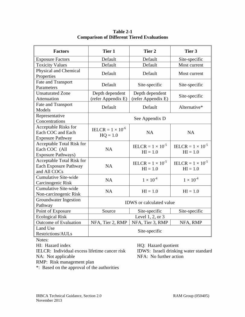
IRBCA Technical Guidance, Section 2.0 RAM Group (050405) November 2013
Table 2-1 Comparison of Different Tiered Evaluations
Factors Tier 1 Tier 2 Tier 3
Exposure Factors Default Default Site-specific Toxicity Values Default Default Most current Physical and Chemical Properties
Default Default Most current
Fate and Transport Parameters
Default Site-specific Site-specific
Unsaturated Zone Attenuation
Depth dependent (refer Appendix E)
Depth dependent (refer Appendix E)
Site-specific
Fate and Transport Models
Default Default Alternative*
Representative Concentrations
See Appendix D
Acceptable Risks for Each COC and Each Exposure Pathway
IELCR = 1 × 10⁻⁶ HQ = 1.0
NA NA
Acceptable Total Risk for Each COC (All Exposure Pathways)
NA IELCR = 1 × 10⁻⁵
HI = 1.0 IELCR = 1 × 10⁻⁵
HI = 1.0
Acceptable Total Risk for Each Exposure Pathway and All COCs
NA IELCR = 1 × 10⁻⁵
HI = 1.0 IELCR = 1 × 10⁻⁵
HI = 1.0
Cumulative Site-wide Carcinogenic Risk
NA 1 × 10⁻⁴ 1 × 10⁻⁴
Cumulative Site-wide Non-carcinogenic Risk
NA HI = 1.0 HI = 1.0
Groundwater Ingestion Pathway
IDWS or calculated value
Point of Exposure Source Site-specific Site-specific Ecological Risk Level 1, 2, or 3 Outcome of Evaluation NFA, Tier 2, RMP NFA, Tier 3, RMP NFA, RMP Land Use Restrictions/AULs
Site-specific
Notes: HI: Hazard index HQ: Hazard quotient IELCR: Individual excess lifetime cancer risk IDWS: Israeli drinking water standard NA: Not applicable NFA: No further action RMP: Risk management plan *: Based on the approval of the authorities
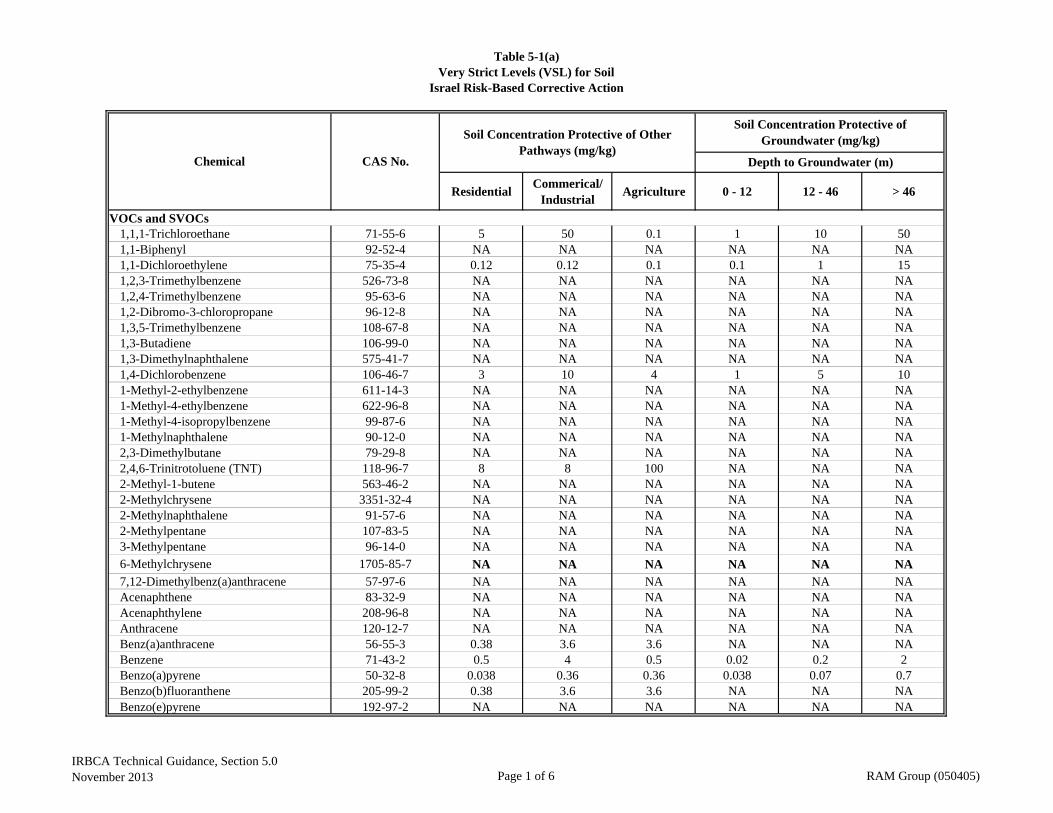
ResidentialCommerical/
IndustrialAgriculture 0 - 12 12 - 46 > 46
VOCs and SVOCs1,1,1-Trichloroethane 71-55-6 5 50 0.1 1 10 501,1-Biphenyl 92-52-4 NA NA NA NA NA NA1,1-Dichloroethylene 75-35-4 0.12 0.12 0.1 0.1 1 151,2,3-Trimethylbenzene 526-73-8 NA NA NA NA NA NA1,2,4-Trimethylbenzene 95-63-6 NA NA NA NA NA NA1,2-Dibromo-3-chloropropane 96-12-8 NA NA NA NA NA NA1,3,5-Trimethylbenzene 108-67-8 NA NA NA NA NA NA1,3-Butadiene 106-99-0 NA NA NA NA NA NA1,3-Dimethylnaphthalene 575-41-7 NA NA NA NA NA NA1,4-Dichlorobenzene 106-46-7 3 10 4 1 5 101-Methyl-2-ethylbenzene 611-14-3 NA NA NA NA NA NA1-Methyl-4-ethylbenzene 622-96-8 NA NA NA NA NA NA1-Methyl-4-isopropylbenzene 99-87-6 NA NA NA NA NA NA1-Methylnaphthalene 90-12-0 NA NA NA NA NA NA2,3-Dimethylbutane 79-29-8 NA NA NA NA NA NA2,4,6-Trinitrotoluene (TNT) 118-96-7 8 8 100 NA NA NA2-Methyl-1-butene 563-46-2 NA NA NA NA NA NA2-Methylchrysene 3351-32-4 NA NA NA NA NA NA2-Methylnaphthalene 91-57-6 NA NA NA NA NA NA2-Methylpentane 107-83-5 NA NA NA NA NA NA3-Methylpentane 96-14-0 NA NA NA NA NA NA6-Methylchrysene 1705-85-7 NA NA NA NA NA NA7,12-Dimethylbenz(a)anthracene 57-97-6 NA NA NA NA NA NAAcenaphthene 83-32-9 NA NA NA NA NA NAAcenaphthylene 208-96-8 NA NA NA NA NA NAAnthracene 120-12-7 NA NA NA NA NA NABenz(a)anthracene 56-55-3 0.38 3.6 3.6 NA NA NABenzene 71-43-2 0.5 4 0.5 0.02 0.2 2Benzo(a)pyrene 50-32-8 0.038 0.36 0.36 0.038 0.07 0.7Benzo(b)fluoranthene 205-99-2 0.38 3.6 3.6 NA NA NABenzo(e)pyrene 192-97-2 NA NA NA NA NA NA
Table 5-1(a)Very Strict Levels (VSL) for Soil
Israel Risk-Based Corrective Action
Chemical CAS No.
Soil Concentration Protective of Groundwater (mg/kg)
Depth to Groundwater (m)
Soil Concentration Protective of Other Pathways (mg/kg)
IRBCA Technical Guidance, Section 5.0November 2013 Page 1 of 6 RAM Group (050405)
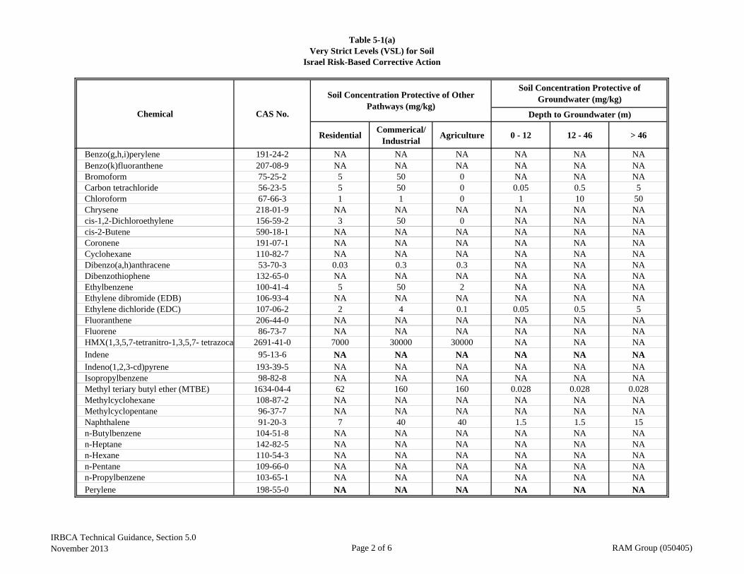
ResidentialCommerical/
IndustrialAgriculture 0 - 12 12 - 46 > 46
Table 5-1(a)Very Strict Levels (VSL) for Soil
Israel Risk-Based Corrective Action
Chemical CAS No.
Soil Concentration Protective of Groundwater (mg/kg)
Depth to Groundwater (m)
Soil Concentration Protective of Other Pathways (mg/kg)
Benzo(g,h,i)perylene 191-24-2 NA NA NA NA NA NABenzo(k)fluoranthene 207-08-9 NA NA NA NA NA NABromoform 75-25-2 5 50 0 NA NA NACarbon tetrachloride 56-23-5 5 50 0 0.05 0.5 5Chloroform 67-66-3 1 1 0 1 10 50Chrysene 218-01-9 NA NA NA NA NA NAcis-1,2-Dichloroethylene 156-59-2 3 50 0 NA NA NAcis-2-Butene 590-18-1 NA NA NA NA NA NACoronene 191-07-1 NA NA NA NA NA NACyclohexane 110-82-7 NA NA NA NA NA NADibenzo(a,h)anthracene 53-70-3 0.03 0.3 0.3 NA NA NADibenzothiophene 132-65-0 NA NA NA NA NA NAEthylbenzene 100-41-4 5 50 2 NA NA NAEthylene dibromide (EDB) 106-93-4 NA NA NA NA NA NAEthylene dichloride (EDC) 107-06-2 2 4 0.1 0.05 0.5 5Fluoranthene 206-44-0 NA NA NA NA NA NAFluorene 86-73-7 NA NA NA NA NA NAHMX(1,3,5,7-tetranitro-1,3,5,7- tetrazocan 2691-41-0 7000 30000 30000 NA NA NAIndene 95-13-6 NA NA NA NA NA NAIndeno(1,2,3-cd)pyrene 193-39-5 NA NA NA NA NA NAIsopropylbenzene 98-82-8 NA NA NA NA NA NAMethyl teriary butyl ether (MTBE) 1634-04-4 62 160 160 0.028 0.028 0.028Methylcyclohexane 108-87-2 NA NA NA NA NA NAMethylcyclopentane 96-37-7 NA NA NA NA NA NANaphthalene 91-20-3 7 40 40 1.5 1.5 15n-Butylbenzene 104-51-8 NA NA NA NA NA NAn-Heptane 142-82-5 NA NA NA NA NA NAn-Hexane 110-54-3 NA NA NA NA NA NAn-Pentane 109-66-0 NA NA NA NA NA NAn-Propylbenzene 103-65-1 NA NA NA NA NA NAPerylene 198-55-0 NA NA NA NA NA NA
IRBCA Technical Guidance, Section 5.0November 2013 Page 2 of 6 RAM Group (050405)
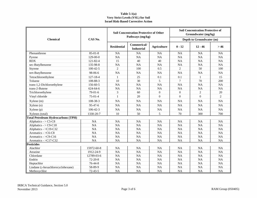
ResidentialCommerical/
IndustrialAgriculture 0 - 12 12 - 46 > 46
Table 5-1(a)Very Strict Levels (VSL) for Soil
Israel Risk-Based Corrective Action
Chemical CAS No.
Soil Concentration Protective of Groundwater (mg/kg)
Depth to Groundwater (m)
Soil Concentration Protective of Other Pathways (mg/kg)
Phenanthrene 85-01-8 NA NA NA NA NA NAPyrene 129-00-0 NA NA NA NA NA NARDX 121-82-4 15 40 40 NA NA NAsec-Butylbenzene 135-98-8 NA NA NA NA NA NAStyrene 100-42-5 2 100 0.5 2 50 100tert-Butylbenzene 98-06-6 NA NA NA NA NA NA
Tetrachloroethylene 127-18-4 1 25 0.1 0.1 1 15Toluene 108-88-3 10 30 5 7 70 200trans-1,2-Dichloroethylene 156-60-5 NA NA NA NA NA NAtrans-2-Butene 624-64-6 NA NA NA NA NA NATrichloroethylene 79-01-6 3 60 0 0 2 20Vinyl chloride 75-01-4 1 20 0 0 0 2
Xylene (m) 108-38-3 NA NA NA NA NA NA
Xylene (o) 95-47-6 NA NA NA NA NA NAXylene (p) 106-42-3 NA NA NA NA NA NA
Xylenes (total) 1330-20-7 10 50 5 70 300 700Total Petroleum Hydrocarbons (TPH)
Aliphatics - > C5-C8 NA NA NA NA NA NA NAAliphatics - > C9-C18 NA NA NA NA NA NA NAAliphatics - >C19-C32 NA NA NA NA NA NA NAAromatics - >C6-C8 NA NA NA NA NA NA NAAromatics - >C9-C16 NA NA NA NA NA NA NAAromatics - >C17-C32 NA NA NA NA NA NA NA
PesticidesAlachlor 15972-60-8 NA NA NA NA NA NAAtrazine 1912-24-9 NA NA NA NA NA NAChlordane 12789-03-6 NA NA NA NA NA NAEndrin 72-20-8 NA NA NA NA NA NAHeptachlor 76-44-8 NA NA NA NA NA NALindane (-hexachlorocyclohexane) 58-89-9 NA NA NA NA NA NAMethoxychlor 72-43-5 NA NA NA NA NA NA
IRBCA Technical Guidance, Section 5.0November 2013 Page 3 of 6 RAM Group (050405)

ResidentialCommerical/
IndustrialAgriculture 0 - 12 12 - 46 > 46
Table 5-1(a)Very Strict Levels (VSL) for Soil
Israel Risk-Based Corrective Action
Chemical CAS No.
Soil Concentration Protective of Groundwater (mg/kg)
Depth to Groundwater (m)
Soil Concentration Protective of Other Pathways (mg/kg)
MetalsArsenic 7440-38-2 17 17 20 15 45 70Cadmium 7440-43-9 10 30 2 6 15 30Chromium (III) 16065-83-1 150 400 100 100 250 400Chromium (VI) 18540-29-9 NA NA NA NA NA NACopper 7440-50-8 150 190 100 14 140 1400Lead 7439-92-1 250 1000 100 40 500 1000Manganese 7439-96-5 2000 6000 2000 1000 3500 6000Mercury (Elemental) 7439-97-6 5 8 10 3 20 20Nickel (Refinary dust) NA NA NA NA NA NA NANickel (Soluble Salts) 7440-02-0 130 500 100 100 300 500Selenium 7782-49-2 5 100 10 3 100 100Silver 7440-22-4 20 200 20 10 100 200Zinc 7440-66-6 300 2500 250 300 1000 2500
InorganicsCyanide 57-12-5 NA NA NA NA NA NA
OthersAsbestos 1332-21-4 NA NA NA NA NA NA3,5-Dinitro-4-chlorobenzotrifluride 393-75-9 1600 4000 4000 NA NA NA2,4/2,6-Dinitrotoluene (DNT) mixture 25321-14-6 2 5 5 NA NA NA
Additional Chemicals(S) NA NA NA NA 1,000 4,000 8,0001,2-Dichloroethylene 540-59-0 3 50 0.1 1 10 501,3-Nitrotoluene (m-nitrotoluene) 99-08-1 600 5,000 5,000 NA NA NA1,4-Nitrotoluene (p-nitrotoluene) 99-99-0 600 5,000 5,000 NA NA NA2,4-dinitrophenol 51-28-5 100 800 800 NA NA NA3-nitrobenzoic acid 121-92-6 500 1,400 1,400 NA NA NAAny single PAH NA 7 40 40 NA NA NABarium 7440-39-3 500 625 500 200 750 1,500Benzoic acid 65-85-0 500 5,000 5,000 NA NA NABoron 7440-42-8 NA NA 20 40 150 400Bromodichloromethane 75-27-4 2.4 2.4 0.1 NA NA NAButyl benzyl pthalate 85-68-7 2,500 4,000 4,000 NA NA NA
IRBCA Technical Guidance, Section 5.0November 2013 Page 4 of 6 RAM Group (050405)
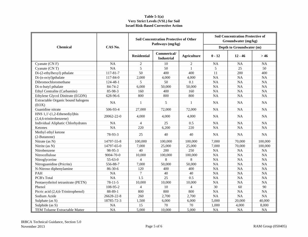
ResidentialCommerical/
IndustrialAgriculture 0 - 12 12 - 46 > 46
Table 5-1(a)Very Strict Levels (VSL) for Soil
Israel Risk-Based Corrective Action
Chemical CAS No.
Soil Concentration Protective of Groundwater (mg/kg)
Depth to Groundwater (m)
Soil Concentration Protective of Other Pathways (mg/kg)
Cyanate (CN F) NA 2 10 2 NA NA NACyanate (CN T) NA 5 50 1 5 25 50Di-(2-ethylhexyl) pthalate 117-81-7 50 400 400 11 200 400Di-(n-octyl)pthalate 117-84-0 2,000 4,000 4,000 NA NA NADibromochloromethane 124-48-1 5 50 0.1 NA NA NADi-n-butyl pthalate 84-74-2 6,000 50,000 50,000 NA NA NAEthyl Centralite (Carbamite) 85-98-3 160 400 160 NA NA NAEthylene Glycol Dinitrate (EGDN) 628-96-6 800 800 800 NA NA NAExtractable Organic bound halogens (EOX)
NA 1 5 1 NA NA NA
Guanidine nitrate 506-93-4 27,000 72,000 72,000 NA NA NAHNS 1,1'-(1,2-Ethenediyl)bis (2,4,6-trinitrobenzene)
20062-22-0 4,000 4,000 4,000 NA NA NA
Individual Aliphatic Chlorhydrates NA 4 25 0.5 NA NA NAKetones NA 220 6,200 220 NA NA NAMethyl ethyl ketone (2-Butanone)
78-93-3 25 40 40 NA NA NA
Nitrate (as N) 14797-55-8 100,000 100,000 100,000 7,000 70,000 100,000Nitrite (as N) 14797-65-0 7,000 25,000 25,000 7,000 70,000 100,000Nitrobenzene 98-95-3 40 200 250 NA NA NANitrocellulose 9004-70-0 10,000 100,000 100,000 NA NA NANitroglycerine 55-63-0 4 8 8 NA NA NANitroguanidine (Pricrite) 556-88-7 7,000 50,000 50,000 NA NA NAN-Nitroso diphenylamine 86-30-6 120 400 400 NA NA NAPAH NA 7 40 40 NA NA NAPCB's Total NA 1.5 25 0.5 NA NA NAPentaerythritol tetranitrate (PETN) 78-11-5 10,000 10,000 10,000 NA NA NAPhenol 108-95-2 4 10 4 30 60 90Picric acid (2,4,6-Trinitrophenol) 88-89-1 800 800 800 NA NA NASodium Azide 26628-22-8 260 2,700 2,700 NA NA NASulphate (as S) 18785-72-3 1,500 6,000 6,000 5,000 20,000 40,000Sulphide (as S) NA 15 70 70 1,000 4,000 8,000TEM Toluene Extractable Matter NA 5,000 10,000 5,000 NA NA NA
IRBCA Technical Guidance, Section 5.0November 2013 Page 5 of 6 RAM Group (050405)

ResidentialCommerical/
IndustrialAgriculture 0 - 12 12 - 46 > 46
Table 5-1(a)Very Strict Levels (VSL) for Soil
Israel Risk-Based Corrective Action
Chemical CAS No.
Soil Concentration Protective of Groundwater (mg/kg)
Depth to Groundwater (m)
Soil Concentration Protective of Other Pathways (mg/kg)
Tetryl (2,4,6-Trinitrophenyl methylnitramine)
479-45-8 650 9,000 9,000 NA NA NA
Thiocyanates (Sulfur CN) 463-56-9 2 10 2 NA NA NATHM's Total NA 5 50 0.1 1 10 50Total Petroleum Hydrocarbons (TPH) NA 100 500 500 100 500 NA
Notes:NA: Not available.
IRBCA Technical Guidance, Section 5.0November 2013 Page 6 of 6 RAM Group (050405)
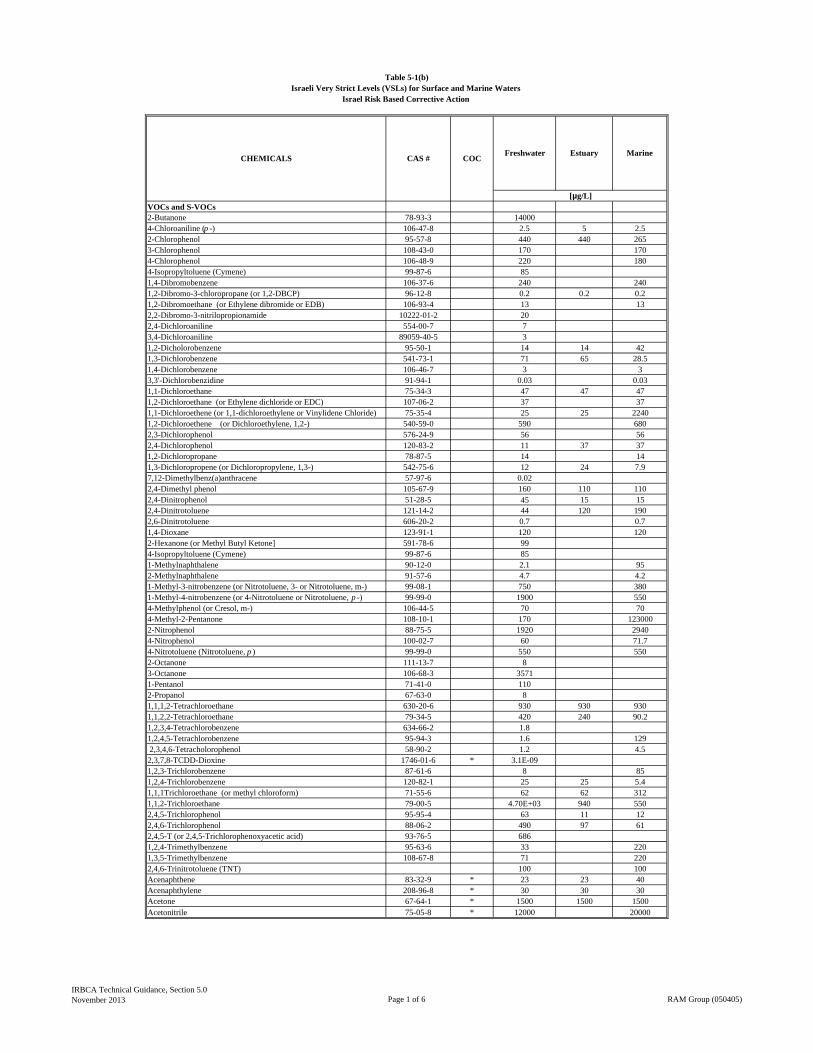
VOCs and S-VOCs2-Butanone 78-93-3 140004-Chloroaniline (p -) 106-47-8 2.5 5 2.52-Chlorophenol 95-57-8 440 440 2653-Chlorophenol 108-43-0 170 1704-Chlorophenol 106-48-9 220 1804-Isopropyltoluene (Cymene) 99-87-6 851,4-Dibromobenzene 106-37-6 240 2401,2-Dibromo-3-chloropropane (or 1,2-DBCP) 96-12-8 0.2 0.2 0.21,2-Dibromoethane (or Ethylene dibromide or EDB) 106-93-4 13 132,2-Dibromo-3-nitrilopropionamide 10222-01-2 202,4-Dichloroaniline 554-00-7 73,4-Dichloroaniline 89059-40-5 31,2-Dicholorobenzene 95-50-1 14 14 421,3-Dichlorobenzene 541-73-1 71 65 28.51,4-Dichlorobenzene 106-46-7 3 33,3'-Dichlorobenzidine 91-94-1 0.03 0.031,1-Dichloroethane 75-34-3 47 47 471,2-Dichloroethane (or Ethylene dichloride or EDC) 107-06-2 37 371,1-Dichloroethene (or 1,1-dichloroethylene or Vinylidene Chloride) 75-35-4 25 25 22401,2-Dichloroethene (or Dichloroethylene, 1,2-) 540-59-0 590 6802,3-Dichlorophenol 576-24-9 56 562,4-Dichlorophenol 120-83-2 11 37 371,2-Dichloropropane 78-87-5 14 141,3-Dichloropropene (or Dichloropropylene, 1,3-) 542-75-6 12 24 7.97,12-Dimethylbenz(a)anthracene 57-97-6 0.022,4-Dimethyl phenol 105-67-9 160 110 1102,4-Dinitrophenol 51-28-5 45 15 152,4-Dinitrotoluene 121-14-2 44 120 1902,6-Dinitrotoluene 606-20-2 0.7 0.71,4-Dioxane 123-91-1 120 1202-Hexanone (or Methyl Butyl Ketone] 591-78-6 994-Isopropyltoluene (Cymene) 99-87-6 851-Methylnaphthalene 90-12-0 2.1 952-Methylnaphthalene 91-57-6 4.7 4.21-Methyl-3-nitrobenzene (or Nitrotoluene, 3- or Nitrotoluene, m-) 99-08-1 750 3801-Methyl-4-nitrobenzene (or 4-Nitrotoluene or Nitrotoluene, p -) 99-99-0 1900 5504-Methylphenol (or Cresol, m-) 106-44-5 70 704-Methyl-2-Pentanone 108-10-1 170 1230002-Nitrophenol 88-75-5 1920 29404-Nitrophenol 100-02-7 60 71.74-Nitrotoluene (Nitrotoluene, p ) 99-99-0 550 5502-Octanone 111-13-7 83-Octanone 106-68-3 35711-Pentanol 71-41-0 1102-Propanol 67-63-0 81,1,1,2-Tetrachloroethane 630-20-6 930 930 9301,1,2,2-Tetrachloroethane 79-34-5 420 240 90.21,2,3,4-Tetrachlorobenzene 634-66-2 1.81,2,4,5-Tetrachlorobenzene 95-94-3 1.6 129 2,3,4,6-Tetracholorophenol 58-90-2 1.2 4.52,3,7,8-TCDD-Dioxine 1746-01-6 * 3.1E-091,2,3-Trichlorobenzene 87-61-6 8 851,2,4-Trichlorobenzene 120-82-1 25 25 5.41,1,1Trichloroethane (or methyl chloroform) 71-55-6 62 62 3121,1,2-Trichloroethane 79-00-5 4.70E+03 940 5502,4,5-Trichlorophenol 95-95-4 63 11 122,4,6-Trichlorophenol 88-06-2 490 97 612,4,5-T (or 2,4,5-Trichlorophenoxyacetic acid) 93-76-5 6861,2,4-Trimethylbenzene 95-63-6 33 2201,3,5-Trimethylbenzene 108-67-8 71 2202,4,6-Trinitrotoluene (TNT) 100 100Acenaphthene 83-32-9 * 23 23 40Acenaphthylene 208-96-8 * 30 30 30Acetone 67-64-1 * 1500 1500 1500Acetonitrile 75-05-8 * 12000 20000
CHEMICALS CAS # COCFreshwater Estuary Marine
[µg/L]
Table 5-1(b)Israeli Very Strict Levels (VSLs) for Surface and Marine Waters
Israel Risk Based Corrective Action
IRBCA Technical Guidance, Section 5.0November 2013 Page 1 of 6 RAM Group (050405)
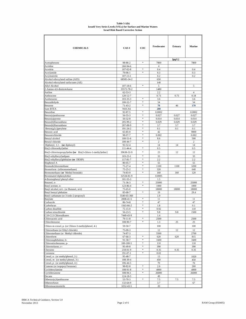
CHEMICALS CAS # COCFreshwater Estuary Marine
[µg/L]
Table 5-1(b)Israeli Very Strict Levels (VSLs) for Surface and Marine Waters
Israel Risk Based Corrective Action
Acetophenone 98-86-2 * 7800 7800Acridine 260-94-6 4Acrolein 107-02-8 * 0.4 0.4Acrylamide 79-06-1 * 0.3 0.3Acrylonitrile 107-13-1 0.2 0.2Alcohol ethoxylated sulfate (AES) 68585-34-2 650Alcohol ethoxylated surfactants (AE) 140Allyl Alcohol 107-18-6 * 5 52-Amino-4,6-dinitrotoluene 35572-78-2 1480Aniline 62-53-3 2.2 4Anthracene 120-12-7 0.73 0.73 0.18Azobenzene 103-33-3 * 3.6 3.6Benzaldehyde 100-52-7 * 54 54Benzene 71-43-2 * 70 46 170Sum BTEX NOCAS 200Benzidine 92-87-5 * 0.0002 0.0002Benzo(a)anthracene 56-55-3 * 0.027 0.027 0.027Benzo(a)pyrene 50-32-8 * 0.014 0.014 0.014Benzo(b)fluoranthene 205-99-2 * 0.029 0.029 0.029Benzo(k)fluoranthene 207-08-9 * 3.7 3.7 3.7 Benzo(g,h,i)perylene 191-24-2 * 0.1 0.1 0.1Benzoic acid 65-85-0 * 42 9000Benzotrichloride 98-07-7 * 0.002 0.002Benzyl alcohol 100-51-6 * 8.6 500Benzyl chloride 100-44-7 * 2 2 Biphenyl, 1,1 - (or diphenyl) 92-52-4 14 14 14Bis(2-chloroethyl)ether 111-44-4 * 0.5 0.5
Bis(2-chloroisopropyl)ether [or Bis(2-chloro-1-methyl)ether] 39638-32-9 * 23 12 12
Bis(2-ethylhexyl)adipate 103-23-1 * 33 33Bis(2-ethylhexyl)phthalate (or DEHP) 117-81-7 * 2.2 2.2Bisphenol A 80-05-7 * 55 55Bromodichloromethane 75-27-4 * 1100 1100 3200Bromoform (tribromomethane) 75-25-2 * 320 640Bromomethane (or Methyl bromide) 74-83-9 * 160 160 120Brominated diphenylether 32534-81-9 0.00054-Bromophenyl phenyl ether 101-55-3 1.5Butanol, n- 71-36-3 * 25000 25000Butyl acetate, n- 123-86-4 * 1000 1000Butyl alcohol, tert - (or Butanol, tert) 75-65-0 18000 18000 18000Butyl benzyl phthalate 85-68-7 * 19 29.4Butyl carbamate (or 3-iodo-2-propynyl) 5540-65-360 1.9Butylate 2008-41-5 * 11 11Carbazole 86-74-8 * 47 47Carbofuran 1563-66-2 * 1.8 0.1Carbon disulfide 75-15-0 * 0.92 110Carbon tetrachloride 56-23-5 * 9.8 9.8 1500C10-C13 Chloroalkanes 7440-43-9 1.4Chloroacetic acid 79-11-8 * 2500 2500Chlorobenzene 108-90-7 * 1.3 25 25
Chloro-m-cresol, p- (or Chloro-3-methylphenol, 4-) 59-50-7 100 100
Chloroethane (or Ethyl chloride) 75-00-3 12 12 12Chloromethane (or Methyl chloride) 74-87-3 5500 2700Chloroform 67-66-3 * 620 620 815Chloronaphthalene, b- 91-58-7 * 1600 1600Chloronitrobenzene, p- 100-100-5 * 110 110Chlorotoluene, o - 95-49-8 * 390 390Chrysene 218-01-9 * 0.35 0.35 0.35Coronene 191-07-1 * 0.02Cresol, o- (or methylphenol, 2-) 95-48-7 13 1020Cresol, m- (or methyl phenol, 3-) 108-39-4 450 450Cresol, p- (or methylphenol, 4-) 106-44-5 70 70Cumene (or isoprpoyl benzene) 98-82-8 * 2.6 260Cyclohexylamine 108-91-8 * 4000 4000Cyclohexanone 108-94-1 * 26000 26000Decane 124-18-5 49Dibenzo(a,h)anthracene 53-70-3 * 7.5 7.5 7.5Dibenzofuran 132-64-9 3.7 67Dibromoacetonitrile 3252-43-5 20
IRBCA Technical Guidance, Section 5.0November 2013 Page 2 of 6 RAM Group (050405)
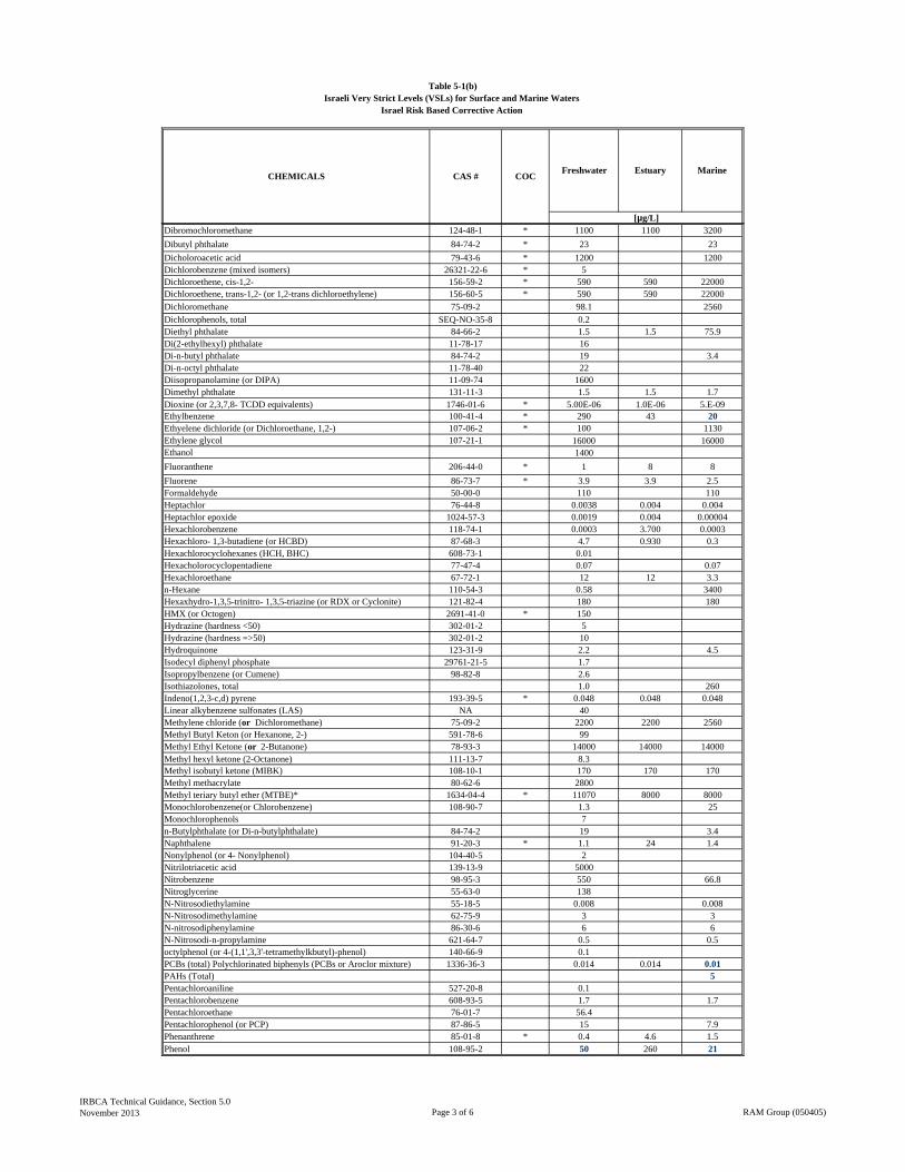
CHEMICALS CAS # COCFreshwater Estuary Marine
[µg/L]
Table 5-1(b)Israeli Very Strict Levels (VSLs) for Surface and Marine Waters
Israel Risk Based Corrective Action
Dibromochloromethane 124-48-1 * 1100 1100 3200
Dibutyl phthalate 84-74-2 * 23 23
Dicholoroacetic acid 79-43-6 * 1200 1200Dichlorobenzene (mixed isomers) 26321-22-6 * 5Dichloroethene, cis-1,2- 156-59-2 * 590 590 22000Dichloroethene, trans-1,2- (or 1,2-trans dichloroethylene) 156-60-5 * 590 590 22000
Dichloromethane 75-09-2 98.1 2560
Dichlorophenols, total SEQ-NO-35-8 0.2Diethyl phthalate 84-66-2 1.5 1.5 75.9Di(2-ethylhexyl) phthalate 11-78-17 16Di-n-butyl phthalate 84-74-2 19 3.4Di-n-octyl phthalate 11-78-40 22Diisopropanolamine (or DIPA) 11-09-74 1600Dimethyl phthalate 131-11-3 1.5 1.5 1.7Dioxine (or 2,3,7,8- TCDD equivalents) 1746-01-6 * 5.00E-06 1.0E-06 5.E-09Ethylbenzene 100-41-4 * 290 43 20Ethyelene dichloride (or Dichloroethane, 1,2-) 107-06-2 * 100 1130Ethylene glycol 107-21-1 16000 16000Ethanol 1400
Fluoranthene 206-44-0 * 1 8 8
Fluorene 86-73-7 * 3.9 3.9 2.5Formaldehyde 50-00-0 110 110Heptachlor 76-44-8 0.0038 0.004 0.004Heptachlor epoxide 1024-57-3 0.0019 0.004 0.00004Hexachlorobenzene 118-74-1 0.0003 3.700 0.0003Hexachloro- 1,3-butadiene (or HCBD) 87-68-3 4.7 0.930 0.3Hexachlorocyclohexanes (HCH, BHC) 608-73-1 0.01Hexacholorocyclopentadiene 77-47-4 0.07 0.07Hexachloroethane 67-72-1 12 12 3.3n-Hexane 110-54-3 0.58 3400Hexaxhydro-1,3,5-trinitro- 1,3,5-triazine (or RDX or Cyclonite) 121-82-4 180 180HMX (or Octogen) 2691-41-0 * 150Hydrazine (hardness <50) 302-01-2 5Hydrazine (hardness =>50) 302-01-2 10Hydroquinone 123-31-9 2.2 4.5Isodecyl diphenyl phosphate 29761-21-5 1.7Isopropylbenzene (or Cumene) 98-82-8 2.6Isothiazolones, total 1.0 260Indeno(1,2,3-c,d) pyrene 193-39-5 * 0.048 0.048 0.048Linear alkybenzene sulfonates (LAS) NA 40Methylene chloride (or Dichloromethane) 75-09-2 2200 2200 2560Methyl Butyl Keton (or Hexanone, 2-) 591-78-6 99Methyl Ethyl Ketone (or 2-Butanone) 78-93-3 14000 14000 14000Methyl hexyl ketone (2-Octanone) 111-13-7 8.3Methyl isobutyl ketone (MIBK) 108-10-1 170 170 170Methyl methacrylate 80-62-6 2800Methyl teriary butyl ether (MTBE)* 1634-04-4 * 11070 8000 8000Monochlorobenzene(or Chlorobenzene) 108-90-7 1.3 25Monochlorophenols 7n-Butylphthalate (or Di-n-butylphthalate) 84-74-2 19 3.4Naphthalene 91-20-3 * 1.1 24 1.4Nonylphenol (or 4- Nonylphenol) 104-40-5 2Nitrilotriacetic acid 139-13-9 5000Nitrobenzene 98-95-3 550 66.8Nitroglycerine 55-63-0 138N-Nitrosodiethylamine 55-18-5 0.008 0.008N-Nitrosodimethylamine 62-75-9 3 3N-nitrosodiphenylamine 86-30-6 6 6N-Nitrosodi-n-propylamine 621-64-7 0.5 0.5octylphenol (or 4-(1,1',3,3'-tetramethylkbutyl)-phenol) 140-66-9 0.1PCBs (total) Polychlorinated biphenyls (PCBs or Aroclor mixture) 1336-36-3 0.014 0.014 0.01PAHs (Total) 5Pentachloroaniline 527-20-8 0.1Pentachlorobenzene 608-93-5 1.7 1.7Pentachloroethane 76-01-7 56.4Pentachlorophenol (or PCP) 87-86-5 15 7.9Phenanthrene 85-01-8 * 0.4 4.6 1.5Phenol 108-95-2 50 260 21
IRBCA Technical Guidance, Section 5.0November 2013 Page 3 of 6 RAM Group (050405)
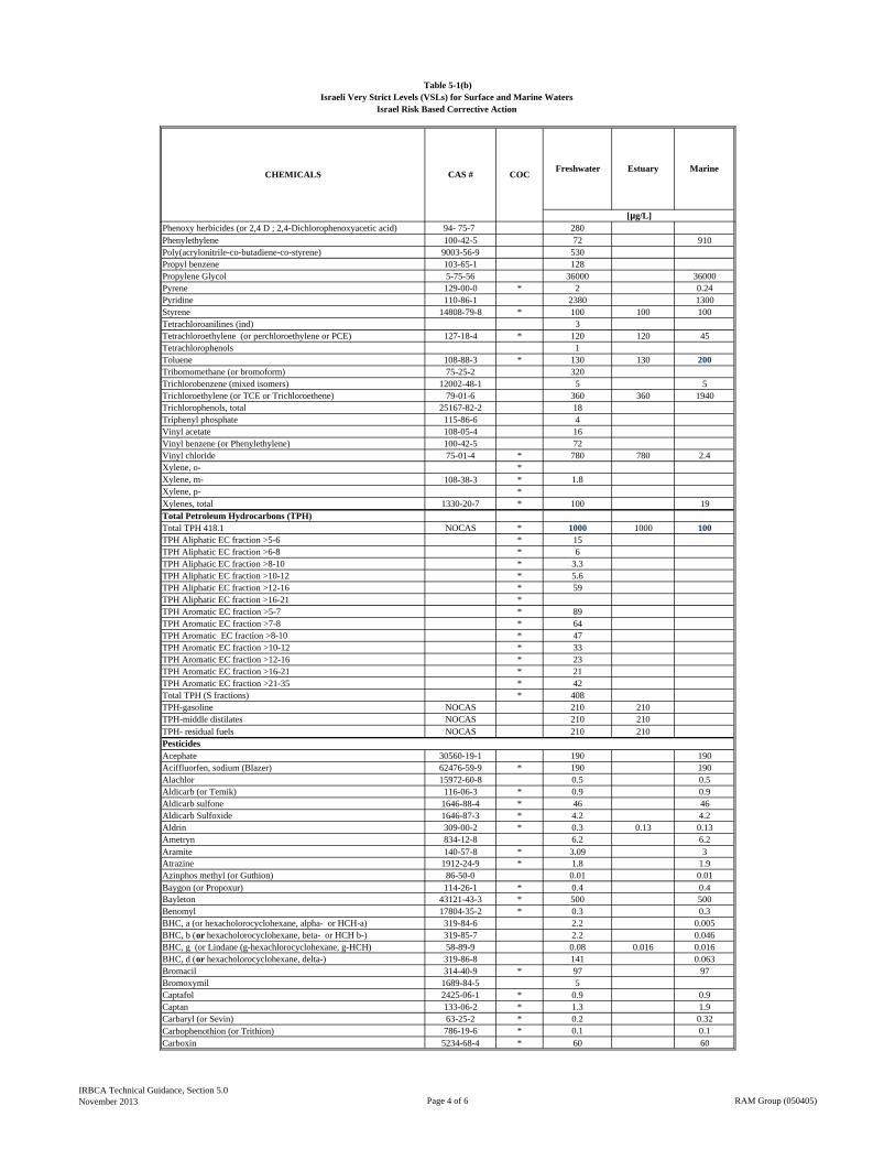
CHEMICALS CAS # COCFreshwater Estuary Marine
[µg/L]
Table 5-1(b)Israeli Very Strict Levels (VSLs) for Surface and Marine Waters
Israel Risk Based Corrective Action
Phenoxy herbicides (or 2,4 D ; 2,4-Dichlorophenoxyacetic acid) 94- 75-7 280Phenylethylene 100-42-5 72 910Poly(acrylonitrile-co-butadiene-co-styrene) 9003-56-9 530Propyl benzene 103-65-1 128Propylene Glycol 5-75-56 36000 36000Pyrene 129-00-0 * 2 0.24Pyridine 110-86-1 2380 1300Styrene 14808-79-8 * 100 100 100Tetrachloroanilines (ind) 3Tetrachloroethylene (or perchloroethylene or PCE) 127-18-4 * 120 120 45Tetrachlorophenols 1Toluene 108-88-3 * 130 130 200Tribomomethane (or bromoform) 75-25-2 320Trichlorobenzene (mixed isomers) 12002-48-1 5 5Trichloroethylene (or TCE or Trichloroethene) 79-01-6 360 360 1940Trichlorophenols, total 25167-82-2 18Triphenyl phosphate 115-86-6 4Vinyl acetate 108-05-4 16Vinyl benzene (or Phenylethylene) 100-42-5 72Vinyl chloride 75-01-4 * 780 780 2.4Xylene, o- *Xylene, m- 108-38-3 * 1.8Xylene, p- *Xylenes, total 1330-20-7 * 100 19Total Petroleum Hydrocarbons (TPH)Total TPH 418.1 NOCAS * 1000 1000 100TPH Aliphatic EC fraction >5-6 * 15TPH Aliphatic EC fraction >6-8 * 6TPH Aliphatic EC fraction >8-10 * 3.3TPH Aliphatic EC fraction >10-12 * 5.6TPH Aliphatic EC fraction >12-16 * 59TPH Aliphatic EC fraction >16-21 *TPH Aromatic EC fraction >5-7 * 89TPH Aromatic EC fraction >7-8 * 64TPH Aromatic EC fraction >8-10 * 47TPH Aromatic EC fraction >10-12 * 33TPH Aromatic EC fraction >12-16 * 23TPH Aromatic EC fraction >16-21 * 21TPH Aromatic EC fraction >21-35 * 42Total TPH (S fractions) * 408TPH-gasoline NOCAS 210 210TPH-middle distilates NOCAS 210 210TPH- residual fuels NOCAS 210 210
Acephate 30560-19-1 190 190Aciffluorfen, sodium (Blazer) 62476-59-9 * 190 190Alachlor 15972-60-8 0.5 0.5Aldicarb (or Temik) 116-06-3 * 0.9 0.9Aldicarb sulfone 1646-88-4 * 46 46Aldicarb Sulfoxide 1646-87-3 * 4.2 4.2Aldrin 309-00-2 * 0.3 0.13 0.13Ametryn 834-12-8 6.2 6.2Aramite 140-57-8 * 3.09 3Atrazine 1912-24-9 * 1.8 1.9Azinphos methyl (or Guthion) 86-50-0 0.01 0.01Baygon (or Propoxur) 114-26-1 * 0.4 0.4Bayleton 43121-43-3 * 500 500Benomyl 17804-35-2 * 0.3 0.3BHC, a (or hexacholorocyclohexane, alpha- or HCH-a) 319-84-6 2.2 0.005BHC, b (or hexacholorocyclohexane, beta- or HCH b-) 319-85-7 2.2 0.046BHC, g (or Lindane (g-hexachlorocyclohexane, g-HCH) 58-89-9 0.08 0.016 0.016BHC, d (or hexacholorocyclohexane, delta-) 319-86-8 141 0.063Bromacil 314-40-9 * 97 97Bromoxymil 1689-84-5 5Captafol 2425-06-1 * 0.9 0.9Captan 133-06-2 * 1.3 1.9Carbaryl (or Sevin) 63-25-2 * 0.2 0.32Carbophenothion (or Trithion) 786-19-6 * 0.1 0.1Carboxin 5234-68-4 * 60 60
Pesticides
IRBCA Technical Guidance, Section 5.0November 2013 Page 4 of 6 RAM Group (050405)
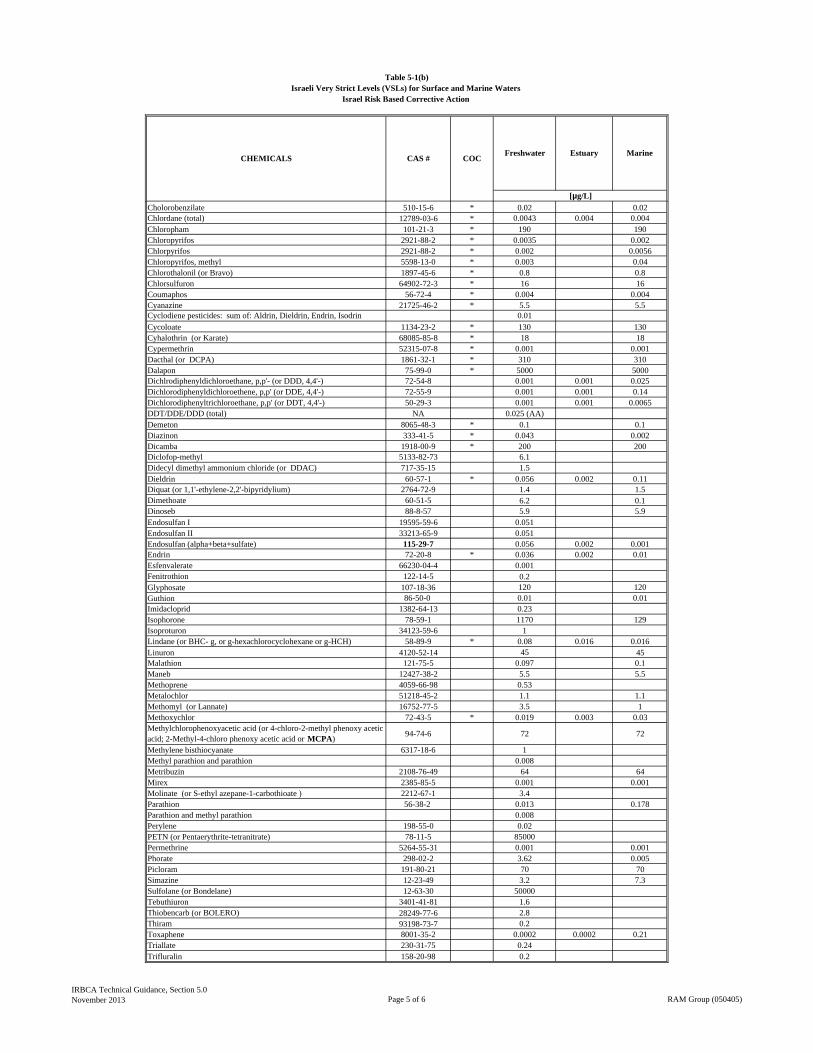
CHEMICALS CAS # COCFreshwater Estuary Marine
[µg/L]
Table 5-1(b)Israeli Very Strict Levels (VSLs) for Surface and Marine Waters
Israel Risk Based Corrective Action
Cholorobenzilate 510-15-6 * 0.02 0.02Chlordane (total) 12789-03-6 * 0.0043 0.004 0.004Chloropham 101-21-3 * 190 190Chloropyrifos 2921-88-2 * 0.0035 0.002Chlorpyrifos 2921-88-2 * 0.002 0.0056Chloropyrifos, methyl 5598-13-0 * 0.003 0.04Chlorothalonil (or Bravo) 1897-45-6 * 0.8 0.8Chlorsulfuron 64902-72-3 * 16 16Coumaphos 56-72-4 * 0.004 0.004Cyanazine 21725-46-2 * 5.5 5.5Cyclodiene pesticides: sum of: Aldrin, Dieldrin, Endrin, Isodrin 0.01
Cycoloate 1134-23-2 * 130 130Cyhalothrin (or Karate) 68085-85-8 * 18 18Cypermethrin 52315-07-8 * 0.001 0.001Dacthal (or DCPA) 1861-32-1 * 310 310Dalapon 75-99-0 * 5000 5000Dichlrodiphenyldichloroethane, p,p'- (or DDD, 4,4'-) 72-54-8 0.001 0.001 0.025Dichlorodiphenyldichloroethene, p,p' (or DDE, 4,4'-) 72-55-9 0.001 0.001 0.14Dichlorodiphenyltrichloroethane, p,p' (or DDT, 4,4'-) 50-29-3 0.001 0.001 0.0065DDT/DDE/DDD (total) NA 0.025 (AA)Demeton 8065-48-3 * 0.1 0.1Diazinon 333-41-5 * 0.043 0.002Dicamba 1918-00-9 * 200 200Diclofop-methyl 5133-82-73 6.1Didecyl dimethyl ammonium chloride (or DDAC) 717-35-15 1.5Dieldrin 60-57-1 * 0.056 0.002 0.11Diquat (or 1,1'-ethylene-2,2'-bipyridylium) 2764-72-9 1.4 1.5Dimethoate 60-51-5 6.2 0.1Dinoseb 88-8-57 5.9 5.9Endosulfan I 19595-59-6 0.051Endosulfan II 33213-65-9 0.051Endosulfan (alpha+beta+sulfate) 115-29-7 0.056 0.002 0.001Endrin 72-20-8 * 0.036 0.002 0.01Esfenvalerate 66230-04-4 0.001Fenitrothion 122-14-5 0.2Glyphosate 107-18-36 120 120Guthion 86-50-0 0.01 0.01Imidacloprid 1382-64-13 0.23Isophorone 78-59-1 1170 129Isoproturon 34123-59-6 1Lindane (or BHC- g, or g-hexachlorocyclohexane or g-HCH) 58-89-9 * 0.08 0.016 0.016Linuron 4120-52-14 45 45Malathion 121-75-5 0.097 0.1Maneb 12427-38-2 5.5 5.5Methoprene 4059-66-98 0.53Metalochlor 51218-45-2 1.1 1.1Methomyl (or Lannate) 16752-77-5 3.5 1Methoxychlor 72-43-5 * 0.019 0.003 0.03Methylchlorophenoxyacetic acid (or 4-chloro-2-methyl phenoxy acetic acid; 2-Methyl-4-chloro phenoxy acetic acid or MCPA)
94-74-6 72 72
Methylene bisthiocyanate 6317-18-6 1Methyl parathion and parathion 0.008Metribuzin 2108-76-49 64 64Mirex 2385-85-5 0.001 0.001Molinate (or S-ethyl azepane-1-carbothioate ) 2212-67-1 3.4Parathion 56-38-2 0.013 0.178Parathion and methyl parathion 0.008Perylene 198-55-0 0.02PETN (or Pentaerythrite-tetranitrate) 78-11-5 85000Permethrine 5264-55-31 0.001 0.001Phorate 298-02-2 3.62 0.005Picloram 191-80-21 70 70Simazine 12-23-49 3.2 7.3Sulfolane (or Bondelane) 12-63-30 50000Tebuthiuron 3401-41-81 1.6Thiobencarb (or BOLERO) 28249-77-6 2.8Thiram 93198-73-7 0.2Toxaphene 8001-35-2 0.0002 0.0002 0.21Triallate 230-31-75 0.24Trifluralin 158-20-98 0.2
IRBCA Technical Guidance, Section 5.0November 2013 Page 5 of 6 RAM Group (050405)
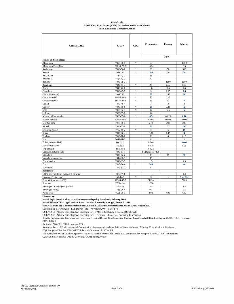
CHEMICALS CAS # COCFreshwater Estuary Marine
[µg/L]
Table 5-1(b)Israeli Very Strict Levels (VSLs) for Surface and Marine Waters
Israel Risk Based Corrective Action
Aluminum 7429-90-5 * 55 1500Aluminum Phosphide 20859-73-8 6.5 6.5Antimony 7440-36-0 * 30 30 500Arsenic NOCAS * 100 36 36Arsenic III 7784-42-1 55Arsenic V 7784-42-1 3.1Barium 7440-39-3 4 1000 1000Beryllium 7440-41-7 * 2.7 0.53 0.53Boron 7440-42-8 1.6 1.6 1.6Cadmium 7440-43-9 * 5 0.25 0.5Chromium (total) NOCAS * 50 180 10Chromium (III) 16065-83-1 * 50 180Chromium (IV) 18540-29-9 * 11 11 5Cobalt 7440-48-4 3 3 3Copper 7440-50-8 * 20 3.10 5Lead 7439-92-1 * 8 5.6 5Lithium 7439-93-2 14Mercury (Elemental) 7439-97-6 * 0.5 0.025 0.16
Methyl mercury 22967-92-6 0.003 0.003 0.003
Molibdenum 7439-98-7 240 240 240
Nickel 7440-02-0 * 50 52 10
Selenium (total) 7782-49-2 * 5 5 60Silver 7440-22-4 0.34 0.19 3Thalium 7440-28-0 20 4 21.3Tin 7440-31-5. 73 2Tributyltin (or TBT) 688-73-3 0.008 0.002Tributyltin oxide 56-35-9 0.026 0.05Triphenyltin 892-20-6 0.022Uranium, soluble salts 7440-61-1 2.6 (hardness=100)Vanadium 7440-62-2 19 19 50Vanadium pentoxide 1314-62-1 15Zinc chloride 7646-85-7 1.5 1.5Zinc 7440-66-6 * 200 40Zirconium 7440-67-7 17
Chlorine cyanide (or cyanogen chloride) 506-77-4 1.4 1.4Cyanide, (Total, free) 57-12-5 * 5 1 5 as CNFluoride (hardness=100) 16984-48-8 2119.4 5000Fluorine 7782-41-4 1080Hydrogen Cyanide (as Cyanide) 74-90-8 3.5 3.5Hydrogen sulfide 7783-06-4 0.1 0.1Perchlorate 7601-90-3 600 600 600
Hierarachy:Israeli EQS: Israel Kishon river Environmental quality Standards, Febuary 2000Israeli Effluent Discharge Levels to Rivers( maximal monthly average), Annex I, 2010MoEP- Marine and Coastal Environment Division: EQS for the Mediterranean Sea in Israel, August 2002California SF Bay RWQCB - ESL Interim Final - November 2007 - Table F-4aUS EPA Mid -Atlantic RSL Regional Screening Levels Marine Ecological Screening BenchmarksUS EPA Mid -Atlantic RSL Regional Screening Levels Freshwater Ecological Screening Benchmarks
Australia- ANZECC 2000 freshwater 95%Australian Dept. of Environment and Conservation: Assessment Levels for Soil, sediment and water, February 2010, Version 4, Revision 1EQS European Directive 2008/105/EC Inland surface waters MAC or AAThe Netherland-Water Quality Objectives - MAC-Maximum Permissible Levels 2002 and Dutch RIVM report 601501021 for TPH fractionsCanadian Environmental Quality Quidelines CCME for freshwater
Florida Department of Environmental Protection Technical Report: Development of Cleanup Target Levels (CTLs) for Chapter 62-777, F.A.C, February, 2005- Table 1
Inorganics
Metals and Metalloids
IRBCA Technical Guidance, Section 5.0November 2013 Page 6 of 6 RAM Group (050405)
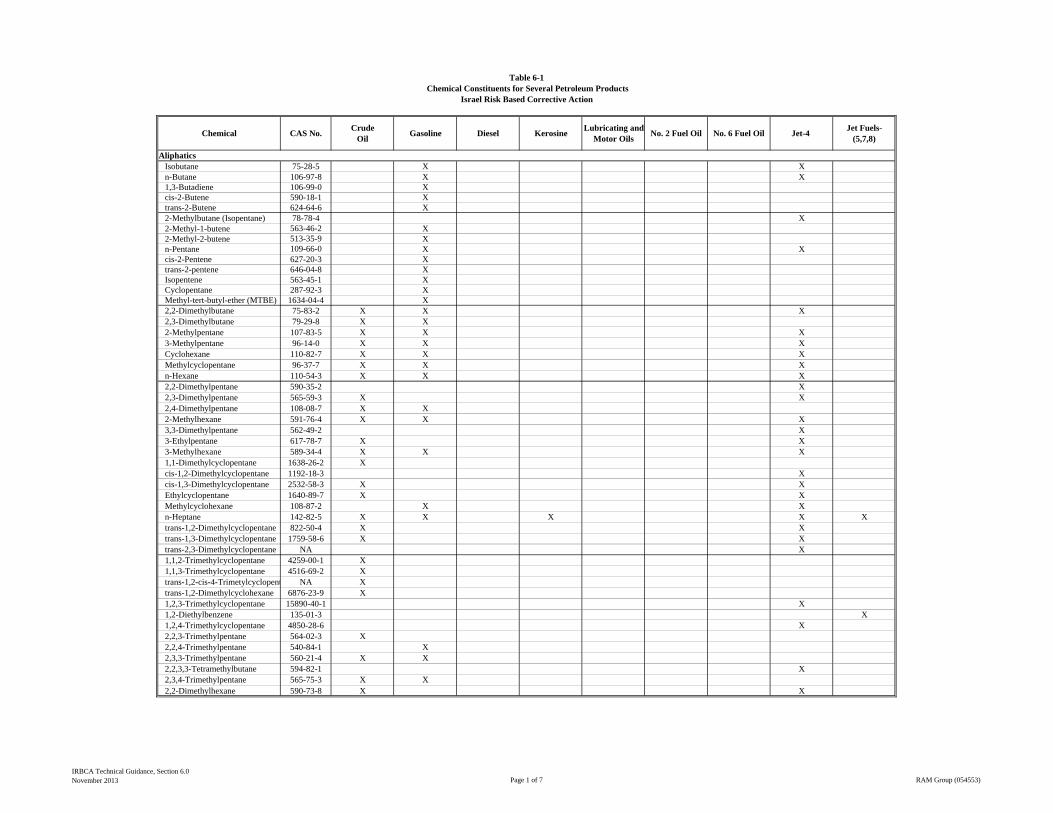
Chemical CAS No.Crude
OilGasoline Diesel Kerosine
Lubricating and Motor Oils
No. 2 Fuel Oil No. 6 Fuel Oil Jet-4 Jet Fuels-
(5,7,8)
Isobutane 75-28-5 X Xn-Butane 106-97-8 X X1,3-Butadiene 106-99-0 Xcis-2-Butene 590-18-1 Xtrans-2-Butene 624-64-6 X2-Methylbutane (Isopentane) 78-78-4 X2-Methyl-1-butene 563-46-2 X2-Methyl-2-butene 513-35-9 Xn-Pentane 109-66-0 X Xcis-2-Pentene 627-20-3 Xtrans-2-pentene 646-04-8 XIsopentene 563-45-1 XCyclopentane 287-92-3 XMethyl-tert-butyl-ether (MTBE) 1634-04-4 X2,2-Dimethylbutane 75-83-2 X X X2,3-Dimethylbutane 79-29-8 X X2-Methylpentane 107-83-5 X X X3-Methylpentane 96-14-0 X X XCyclohexane 110-82-7 X X XMethylcyclopentane 96-37-7 X X Xn-Hexane 110-54-3 X X X2,2-Dimethylpentane 590-35-2 X2,3-Dimethylpentane 565-59-3 X X2,4-Dimethylpentane 108-08-7 X X2-Methylhexane 591-76-4 X X X3,3-Dimethylpentane 562-49-2 X3-Ethylpentane 617-78-7 X X3-Methylhexane 589-34-4 X X X1,1-Dimethylcyclopentane 1638-26-2 Xcis-1,2-Dimethylcyclopentane 1192-18-3 Xcis-1,3-Dimethylcyclopentane 2532-58-3 X XEthylcyclopentane 1640-89-7 X XMethylcyclohexane 108-87-2 X Xn-Heptane 142-82-5 X X X X Xtrans-1,2-Dimethylcyclopentane 822-50-4 X Xtrans-1,3-Dimethylcyclopentane 1759-58-6 X Xtrans-2,3-Dimethylcyclopentane NA X1,1,2-Trimethylcyclopentane 4259-00-1 X1,1,3-Trimethylcyclopentane 4516-69-2 Xtrans-1,2-cis-4-Trimetylcyclopent NA Xtrans-1,2-Dimethylcyclohexane 6876-23-9 X1,2,3-Trimethylcyclopentane 15890-40-1 X1,2-Diethylbenzene 135-01-3 X1,2,4-Trimethylcyclopentane 4850-28-6 X2,2,3-Trimethylpentane 564-02-3 X2,2,4-Trimethylpentane 540-84-1 X2,3,3-Trimethylpentane 560-21-4 X X2,2,3,3-Tetramethylbutane 594-82-1 X2,3,4-Trimethylpentane 565-75-3 X X2,2-Dimethylhexane 590-73-8 X X
Table 6-1Chemical Constituents for Several Petroleum Products
Aliphatics
Israel Risk Based Corrective Action
IRBCA Technical Guidance, Section 6.0November 2013 Page 1 of 7 RAM Group (054553)
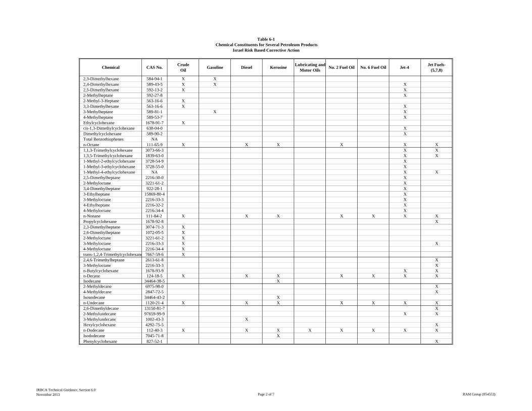
Chemical CAS No.Crude
OilGasoline Diesel Kerosine
Lubricating and Motor Oils
No. 2 Fuel Oil No. 6 Fuel Oil Jet-4 Jet Fuels-
(5,7,8)
Table 6-1Chemical Constituents for Several Petroleum Products
Israel Risk Based Corrective Action
2,3-Dimethylhexane 584-94-1 X X2,4-Dimethylhexane 589-43-5 X X X2,5-Dimethylhexane 592-13-2 X X2-Methylheptane 592-27-8 X2-Methyl-3-Heptane 563-16-6 X3,3-Dimethylhexane 563-16-6 X X3-Methylheptane 589-81-1 X X4-Methylheptane 589-53-7 XEthylcyclohexane 1678-91-7 Xcis-1,3-Dimethylcyclohexane 638-04-0 XDimethylcyclohexane 589-90-2 XTotal Benzothiophenes NAn-Octane 111-65-9 X X X X X X1,1,3-Trimethylcyclohexane 3073-66-3 X X1,3,5-Trimethylcyclohexane 1839-63-0 X X1-Methyl-2-ethylcyclohexane 3728-54-9 X1-Methyl-3-ethylcyclohexane 3728-55-0 X1-Methyl-4-ethylcyclohexane NA X X2,5-Dimethylheptane 2216-30-0 X2-Methyloctane 3221-61-2 X3,4-Dimethylheptane 922-28-1 X3-Ethylheptane 15869-80-4 X3-Methyloctane 2216-33-3 X4-Ethylheptane 2216-32-2 X4-Methyloctane 2216-34-4 Xn-Nonane 111-84-2 X X X X X X XPropylcyclohexane 1678-92-8 X2,3-Dimethylheptane 3074-71-3 X2,6-Dimethylheptane 1072-05-5 X2-Methyloctane 3221-61-2 X3-Methyloctane 2216-33-3 X X4-Methyloctane 2216-34-4 Xtrans-1,2,4-Trimethylcyclohexane 7667-59-6 X2,4,6-Trimethylheptane 2613-61-8 X3-Methyloctane 2216-33-3 Xn-Butylcyclohexane 1678-93-9 X Xn-Decane 124-18-5 X X X X X X XIsodecane 34464-38-5 X2-Methyldecane 6975-98-0 X4-Methyldecane 2847-72-5 XIsoundecane 34464-43-2 Xn-Undecane 1120-21-4 X X X X X X X2,6-Dimethyldecane 13150-81-7 X2-Methylundecane 97659-99-9 X X3-Methylundecane 1002-43-3 XHexylcyclohexane 4292-75-5 Xn-Dodecane 112-40-3 X X X X X X X XIsododecane 7045-71-8 XPhenylcyclohexane 827-52-1 X
IRBCA Technical Guidance, Section 6.0November 2013 Page 2 of 7 RAM Group (054553)
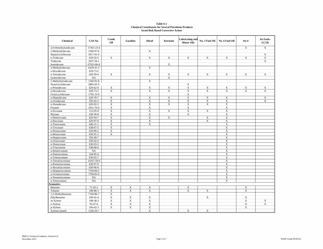
Chemical CAS No.Crude
OilGasoline Diesel Kerosine
Lubricating and Motor Oils
No. 2 Fuel Oil No. 6 Fuel Oil Jet-4 Jet Fuels-
(5,7,8)
Table 6-1Chemical Constituents for Several Petroleum Products
Israel Risk Based Corrective Action
2,6-Dimethylundecane 17301-23-4 X X2-Methyldodecane 1560-97-0 XHeptylcyclohexane 5617-41-4 Xn-Tridecane 629-50-5 X X X X X X X XTridecene 2437-56-1 XIsotridecane 67923-86-8 X3-Methyltridecane 6418-41-3 Xn-Hexadecane 629-73-2n-Tetradecane 629-59-4 X X X X X X X XIsotetradecane NA X2-Methyltetradecane 1560-95-8 XNonylcyclohexane 2883-02-5 Xn-Pentadecane 629-62-9 X X X X X X X Xn-Hexadecane 629-73-2 X X X X X X X XOctylcyclohexane 1795-15-9 Xn-Heptadecane 629-78-7 X X X X X X Xn-Octadecane 593-45-3 X X X X X X Xn-Nonadecane 629-92-5 X X X X X XPristane 1921-70-6 X X X Xn-Eicosane 112-95-8 X X X X X XPhytane 638-36-8 X X X Xn-Heneicosane 629-94-7 X X X X Xn-Docosane 629-97-0 X X X Xn-Tetracosane 646-31-1 X X Xn-Tricosane 638-67-5 X Xn-Pentacosane 629-99-2 X Xn-Hexacosane 630-01-3 X Xn-Heptacosane 593-49-7 Xn-Octacosane 630-02-4 Xn-Nonacosane 630-03-5 Xn-Triacontane 638-68-6 Xn-Hentricontane NA Xn-Dotriacontane 544-85-4 Xn-Tritriacontane 630-05-7 Xn-Tetratriacontane 14167-59-0 Xn-Pentatriacontane 630-07-9 Xn-Hexatriacontane 630-06-8 Xn-Heptatriacontane 7194-84-5 Xn-Octatriacontane 7194-85-6 Xn-Nonatriacontane NA Xn-Tetracontane NA X
Benzene 71-43-2 X X X X XToluene 108-88-3 X X X X X X1,2-Diethylbenzene 7194-86-7 XEthylbenzene 100-41-4 X X X X Xm-Xylene 108-38-3 X X X X Xo-Xylene 95-47-6 X X X X Xp-Xylene 106-42-3 X X X XXylenes (total) 1330-20-7 X X X
Aromatics
IRBCA Technical Guidance, Section 6.0November 2013 Page 3 of 7 RAM Group (054553)
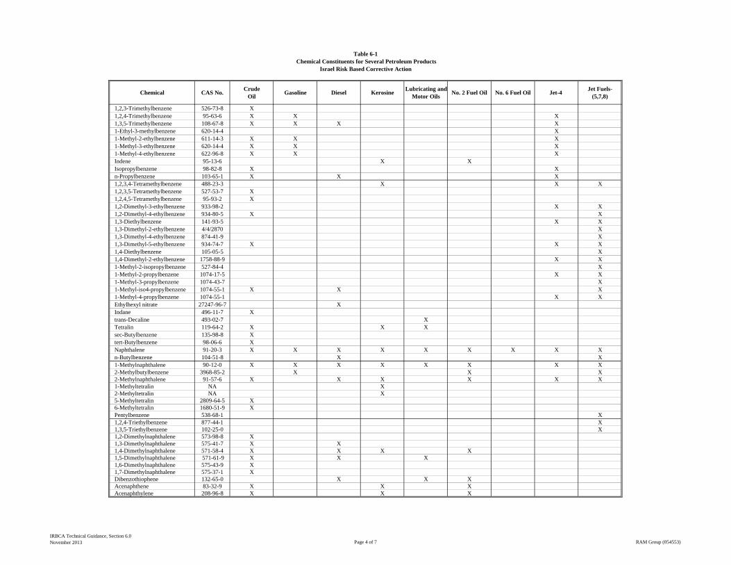
Chemical CAS No.Crude
OilGasoline Diesel Kerosine
Lubricating and Motor Oils
No. 2 Fuel Oil No. 6 Fuel Oil Jet-4 Jet Fuels-
(5,7,8)
Table 6-1Chemical Constituents for Several Petroleum Products
Israel Risk Based Corrective Action
1,2,3-Trimethylbenzene 526-73-8 X1,2,4-Trimethylbenzene 95-63-6 X X X1,3,5-Trimethylbenzene 108-67-8 X X X X1-Ethyl-3-methylbenzene 620-14-4 X1-Methyl-2-ethylbenzene 611-14-3 X X X1-Methyl-3-ethylbenzene 620-14-4 X X X1-Methyl-4-ethylbenzene 622-96-8 X X XIndene 95-13-6 X XIsopropylbenzene 98-82-8 X Xn-Propylbenzene 103-65-1 X X X1,2,3,4-Tetramethylbenzene 488-23-3 X X X1,2,3,5-Tetramethylbenzene 527-53-7 X1,2,4,5-Tetramethylbenzene 95-93-2 X1,2-Dimethyl-3-ethylbenzene 933-98-2 X X1,2-Dimethyl-4-ethylbenzene 934-80-5 X X1,3-Diethylbenzene 141-93-5 X X1,3-Dimethyl-2-ethylbenzene 4/4/2870 X1,3-Dimethyl-4-ethylbenzene 874-41-9 X1,3-Dimethyl-5-ethylbenzene 934-74-7 X X X1,4-Diethylbenzene 105-05-5 X1,4-Dimethyl-2-ethylbenzene 1758-88-9 X X1-Methyl-2-isopropylbenzene 527-84-4 X1-Methyl-2-propylbenzene 1074-17-5 X X1-Methyl-3-propylbenzene 1074-43-7 X1-Methyl-iso4-propylbenzene 1074-55-1 X X X1-Methyl-4-propylbenzene 1074-55-1 X XEthylhexyl nitrate 27247-96-7 XIndane 496-11-7 Xtrans-Decaline 493-02-7 XTetralin 119-64-2 X X Xsec-Butylbenzene 135-98-8 Xtert-Butylbenzene 98-06-6 XNaphthalene 91-20-3 X X X X X X X X Xn-Butylbenzene 104-51-8 X X1-Methylnaphthalene 90-12-0 X X X X X X X X2-Methylbutylbenzene 3968-85-2 X X X2-Methylnaphthalene 91-57-6 X X X X X X1-Methyltetralin NA X2-Methyltetralin NA X5-Methyltetralin 2809-64-5 X6-Methyltetralin 1680-51-9 XPentylbenzene 538-68-1 X1,2,4-Triethylbenzene 877-44-1 X1,3,5-Triethylbenzene 102-25-0 X1,2-Dimethylnaphthalene 573-98-8 X1,3-Dimethylnaphthalene 575-41-7 X X1,4-Dimethylnaphthalene 571-58-4 X X X X1,5-Dimethylnaphthalene 571-61-9 X X X1,6-Dimethylnaphthalene 575-43-9 X1,7-Dimethylnaphthalene 575-37-1 XDibenzothiophene 132-65-0 X X XAcenaphthene 83-32-9 X X XAcenaphthylene 208-96-8 X X X
IRBCA Technical Guidance, Section 6.0November 2013 Page 4 of 7 RAM Group (054553)
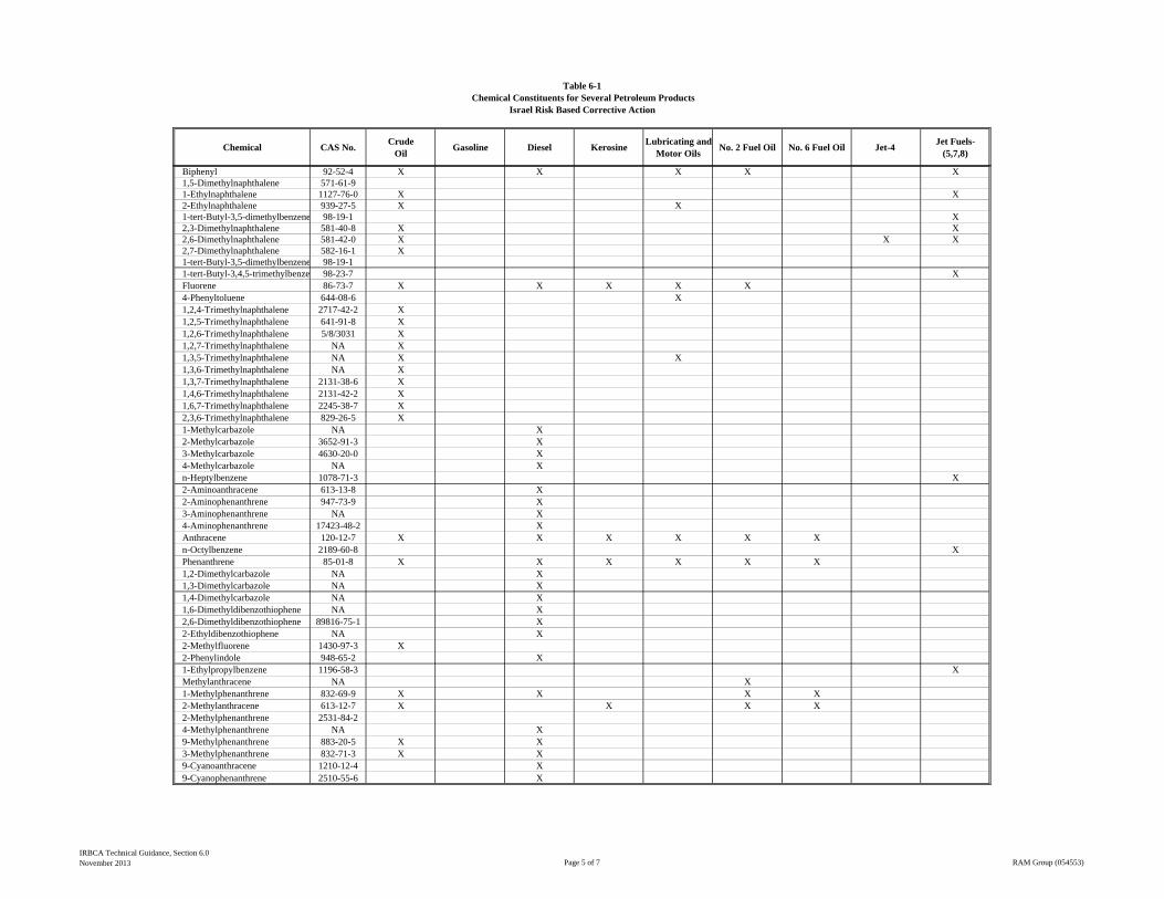
Chemical CAS No.Crude
OilGasoline Diesel Kerosine
Lubricating and Motor Oils
No. 2 Fuel Oil No. 6 Fuel Oil Jet-4 Jet Fuels-
(5,7,8)
Table 6-1Chemical Constituents for Several Petroleum Products
Israel Risk Based Corrective Action
Biphenyl 92-52-4 X X X X X1,5-Dimethylnaphthalene 571-61-91-Ethylnaphthalene 1127-76-0 X X2-Ethylnaphthalene 939-27-5 X X1-tert-Butyl-3,5-dimethylbenzene 98-19-1 X2,3-Dimethylnaphthalene 581-40-8 X X2,6-Dimethylnaphthalene 581-42-0 X X X2,7-Dimethylnaphthalene 582-16-1 X1-tert-Butyl-3,5-dimethylbenzene 98-19-11-tert-Butyl-3,4,5-trimethylbenze 98-23-7 XFluorene 86-73-7 X X X X X4-Phenyltoluene 644-08-6 X1,2,4-Trimethylnaphthalene 2717-42-2 X1,2,5-Trimethylnaphthalene 641-91-8 X1,2,6-Trimethylnaphthalene 5/8/3031 X1,2,7-Trimethylnaphthalene NA X1,3,5-Trimethylnaphthalene NA X X1,3,6-Trimethylnaphthalene NA X1,3,7-Trimethylnaphthalene 2131-38-6 X1,4,6-Trimethylnaphthalene 2131-42-2 X1,6,7-Trimethylnaphthalene 2245-38-7 X2,3,6-Trimethylnaphthalene 829-26-5 X1-Methylcarbazole NA X2-Methylcarbazole 3652-91-3 X3-Methylcarbazole 4630-20-0 X4-Methylcarbazole NA Xn-Heptylbenzene 1078-71-3 X2-Aminoanthracene 613-13-8 X2-Aminophenanthrene 947-73-9 X3-Aminophenanthrene NA X4-Aminophenanthrene 17423-48-2 XAnthracene 120-12-7 X X X X X Xn-Octylbenzene 2189-60-8 XPhenanthrene 85-01-8 X X X X X X1,2-Dimethylcarbazole NA X1,3-Dimethylcarbazole NA X1,4-Dimethylcarbazole NA X1,6-Dimethyldibenzothiophene NA X2,6-Dimethyldibenzothiophene 89816-75-1 X2-Ethyldibenzothiophene NA X2-Methylfluorene 1430-97-3 X2-Phenylindole 948-65-2 X1-Ethylpropylbenzene 1196-58-3 XMethylanthracene NA X1-Methylphenanthrene 832-69-9 X X X X2-Methylanthracene 613-12-7 X X X X2-Methylphenanthrene 2531-84-24-Methylphenanthrene NA X9-Methylphenanthrene 883-20-5 X X3-Methylphenanthrene 832-71-3 X X9-Cyanoanthracene 1210-12-4 X9-Cyanophenanthrene 2510-55-6 X
IRBCA Technical Guidance, Section 6.0November 2013 Page 5 of 7 RAM Group (054553)
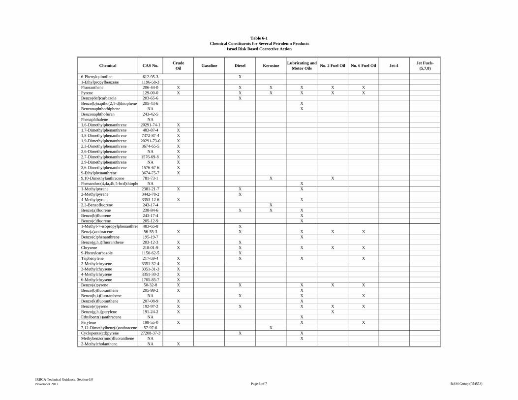
Chemical CAS No.Crude
OilGasoline Diesel Kerosine
Lubricating and Motor Oils
No. 2 Fuel Oil No. 6 Fuel Oil Jet-4 Jet Fuels-
(5,7,8)
Table 6-1Chemical Constituents for Several Petroleum Products
Israel Risk Based Corrective Action
6-Phenylquinoline 612-95-3 X1-Ethylpropylbenzene 1196-58-3Fluoranthene 206-44-0 X X X X X XPyrene 129-00-0 X X X X X XBenzo(def)carbazole 203-65-6 XBenzo(b)naptho(2,1-d)thiophene 205-43-6 XBenzonaphthothiphene NA XBenzonaphthofuran 243-42-5Phenaphthalene NA1,6-Dimethylphenanthrene 20291-74-1 X1,7-Dimethylphenanthrene 483-87-4 X1,8-Dimethylphenanthrene 7372-87-4 X1,9-Dimethylphenanthrene 20291-73-0 X2,3-Dimethylphenanthrene 3674-65-5 X2,6-Dimethylphenanthrene NA X2,7-Dimethylphenanthrene 1576-69-8 X2,9-Dimethylphenanthrene NA X3,6-Dimethylphenanthrene 1576-67-6 X9-Ethylphenanthrene 3674-75-7 X9,10-Dimethylanthracene 781-73-1 X XPhenanthro(4,4a,4b,5-bcd)thiophe NA X1-Methylpyrene 2381-21-7 X X X2-Methylpyrene 3442-78-2 X4-Methylpyrene 3353-12-6 X X2,3-Benzofluorene 243-17-4 XBenzo(a)fluorene 238-84-6 X X XBenzo(b)fluorene 243-17-4 XBenzo(c)fluorene 205-12-9 X1-Methyl-7-isopropylphenanthren 483-65-8 XBenz(a)anthracene 56-55-3 X X X X XBenzo(c)phenanthrene 195-19-7 XBenzo(g,h,i)fluoranthene 203-12-3 X XChrysene 218-01-9 X X X X X9-Phenylcarbazole 1150-62-5 XTriphenylene 217-59-4 X X X X2-Methylchrysene 3351-32-4 X3-Methylchrysene 3351-31-3 X4-Methylchrysene 3351-30-2 X6-Methylchrysene 1705-85-7 XBenzo(a)pyrene 50-32-8 X X X X XBenzo(b)fluoranthene 205-99-2 X XBenzo(b,k)fluoranthene NA X X XBenzo(k)fluoranthene 207-08-9 X XBenzo(e)pyrene 192-97-2 X X X X XBenzo(g,h,i)perylene 191-24-2 X XEthylbenz(a)anthracene NA XPerylene 198-55-0 X X X7,12-Dimethylbenz(a)anthracene 57-97-6 XCyclopenta(cd)pyrene 27208-37-3 X XMethybenzo(mno)fluoranthene NA X2-Methylcholanthene NA X
IRBCA Technical Guidance, Section 6.0November 2013 Page 6 of 7 RAM Group (054553)
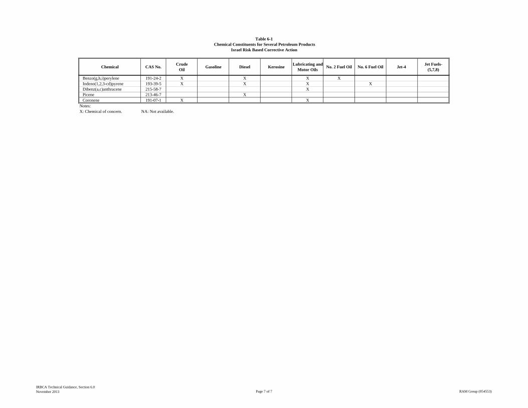
Chemical CAS No.Crude
OilGasoline Diesel Kerosine
Lubricating and Motor Oils
No. 2 Fuel Oil No. 6 Fuel Oil Jet-4 Jet Fuels-
(5,7,8)
Table 6-1Chemical Constituents for Several Petroleum Products
Israel Risk Based Corrective Action
Benzo(g,h,i)perylene 191-24-2 X X X XIndeno(1,2,3-cd)pyrene 193-39-5 X X X XDibenz(a,c)anthracene 215-58-7 XPicene 213-46-7 XCoronene 191-07-1 X X
Notes:X: Chemical of concern. NA: Not available.
IRBCA Technical Guidance, Section 6.0November 2013 Page 7 of 7 RAM Group (054553)
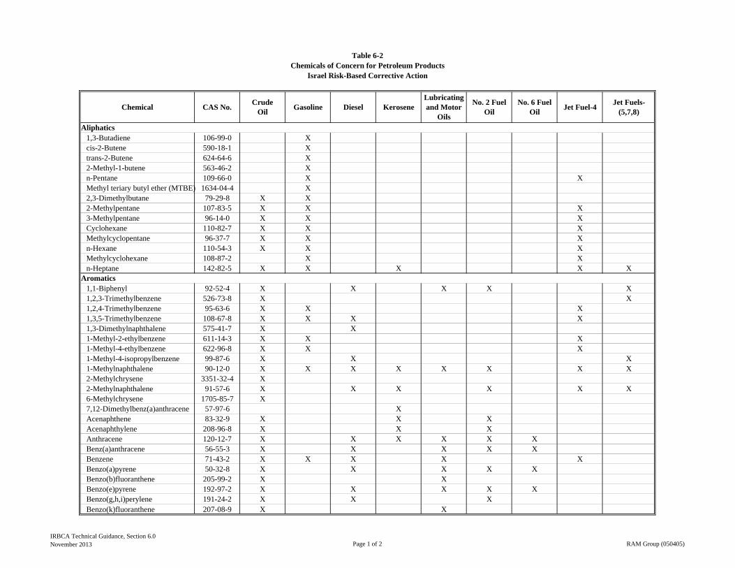
Chemical CAS No.Crude
OilGasoline Diesel Kerosene
Lubricating and Motor
Oils
No. 2 Fuel Oil
No. 6 Fuel Oil
Jet Fuel-4Jet Fuels-
(5,7,8)
1,3-Butadiene 106-99-0 Xcis-2-Butene 590-18-1 Xtrans-2-Butene 624-64-6 X2-Methyl-1-butene 563-46-2 Xn-Pentane 109-66-0 X XMethyl teriary butyl ether (MTBE) 1634-04-4 X2,3-Dimethylbutane 79-29-8 X X2-Methylpentane 107-83-5 X X X3-Methylpentane 96-14-0 X X XCyclohexane 110-82-7 X X XMethylcyclopentane 96-37-7 X X Xn-Hexane 110-54-3 X X XMethylcyclohexane 108-87-2 X Xn-Heptane 142-82-5 X X X X X
1,1-Biphenyl 92-52-4 X X X X X1,2,3-Trimethylbenzene 526-73-8 X X1,2,4-Trimethylbenzene 95-63-6 X X X1,3,5-Trimethylbenzene 108-67-8 X X X X1,3-Dimethylnaphthalene 575-41-7 X X1-Methyl-2-ethylbenzene 611-14-3 X X X1-Methyl-4-ethylbenzene 622-96-8 X X X1-Methyl-4-isopropylbenzene 99-87-6 X X X1-Methylnaphthalene 90-12-0 X X X X X X X X2-Methylchrysene 3351-32-4 X2-Methylnaphthalene 91-57-6 X X X X X X6-Methylchrysene 1705-85-7 X7,12-Dimethylbenz(a)anthracene 57-97-6 XAcenaphthene 83-32-9 X X XAcenaphthylene 208-96-8 X X XAnthracene 120-12-7 X X X X X XBenz(a)anthracene 56-55-3 X X X X XBenzene 71-43-2 X X X X XBenzo(a)pyrene 50-32-8 X X X X XBenzo(b)fluoranthene 205-99-2 X XBenzo(e)pyrene 192-97-2 X X X X XBenzo(g,h,i)perylene 191-24-2 X X XBenzo(k)fluoranthene 207-08-9 X X
Aromatics
Table 6-2Chemicals of Concern for Petroleum Products
Israel Risk-Based Corrective Action
Aliphatics
IRBCA Technical Guidance, Section 6.0November 2013 Page 1 of 2 RAM Group (050405)
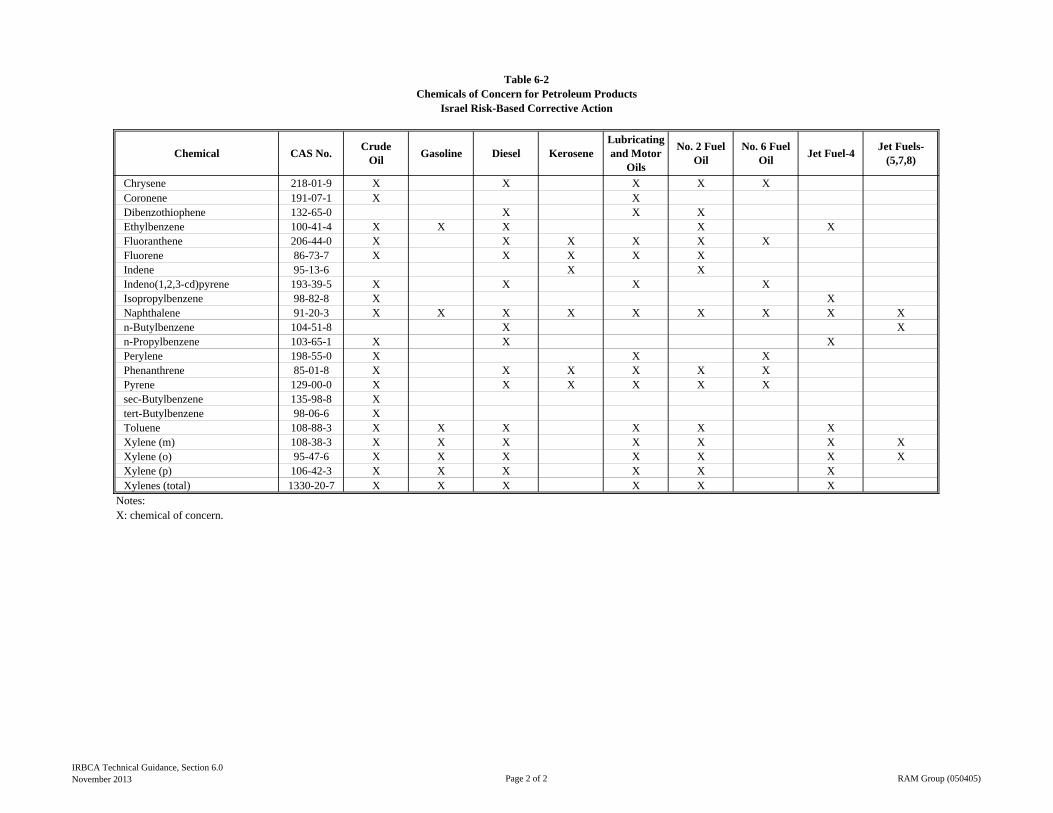
Chemical CAS No.Crude
OilGasoline Diesel Kerosene
Lubricating and Motor
Oils
No. 2 Fuel Oil
No. 6 Fuel Oil
Jet Fuel-4Jet Fuels-
(5,7,8)
Table 6-2Chemicals of Concern for Petroleum Products
Israel Risk-Based Corrective Action
Chrysene 218-01-9 X X X X XCoronene 191-07-1 X XDibenzothiophene 132-65-0 X X XEthylbenzene 100-41-4 X X X X XFluoranthene 206-44-0 X X X X X XFluorene 86-73-7 X X X X XIndene 95-13-6 X XIndeno(1,2,3-cd)pyrene 193-39-5 X X X XIsopropylbenzene 98-82-8 X XNaphthalene 91-20-3 X X X X X X X X Xn-Butylbenzene 104-51-8 X Xn-Propylbenzene 103-65-1 X X XPerylene 198-55-0 X X XPhenanthrene 85-01-8 X X X X X XPyrene 129-00-0 X X X X X Xsec-Butylbenzene 135-98-8 Xtert-Butylbenzene 98-06-6 XToluene 108-88-3 X X X X X XXylene (m) 108-38-3 X X X X X X XXylene (o) 95-47-6 X X X X X X XXylene (p) 106-42-3 X X X X X XXylenes (total) 1330-20-7 X X X X X X
Notes:X: chemical of concern.
IRBCA Technical Guidance, Section 6.0November 2013 Page 2 of 2 RAM Group (050405)
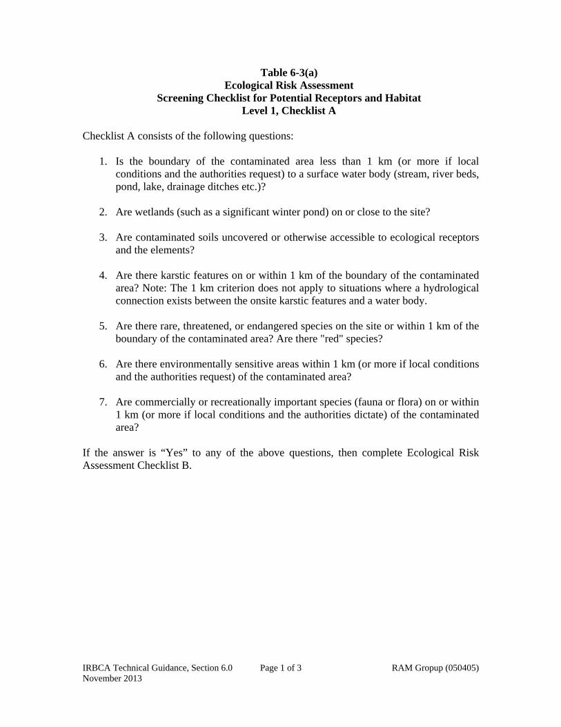
IRBCA Technical Guidance, Section 6.0 Page 1 of 3 RAM Gropup (050405) November 2013
Table 6-3(a) Ecological Risk Assessment
Screening Checklist for Potential Receptors and Habitat Level 1, Checklist A
Checklist A consists of the following questions:
1. Is the boundary of the contaminated area less than 1 km (or more if local
conditions and the authorities request) to a surface water body (stream, river beds, pond, lake, drainage ditches etc.)?
2. Are wetlands (such as a significant winter pond) on or close to the site?
3. Are contaminated soils uncovered or otherwise accessible to ecological receptors
and the elements?
4. Are there karstic features on or within 1 km of the boundary of the contaminated area? Note: The 1 km criterion does not apply to situations where a hydrological connection exists between the onsite karstic features and a water body.
5. Are there rare, threatened, or endangered species on the site or within 1 km of the
boundary of the contaminated area? Are there "red" species?
6. Are there environmentally sensitive areas within 1 km (or more if local conditions and the authorities request) of the contaminated area?
7. Are commercially or recreationally important species (fauna or flora) on or within
1 km (or more if local conditions and the authorities dictate) of the contaminated area?
If the answer is “Yes” to any of the above questions, then complete Ecological Risk Assessment Checklist B.

IRBCA Technical Guidance, Section 6.0 Page 2 of 3 RAM Gropup (050405) November 2013
Table 6-3(b) Ecological Risk Assessment
Screening Checklist for Potential Receptors and Habitat Level 1, Checklist B
Question 1: Could contaminants associated with the site reach ecological receptors and/or habitats via groundwater? 1. a.) Can contaminants associated with the site leach, dissolve, or otherwise migrate to
groundwater? 1.b.) Are contaminants associated with the site mobile in groundwater? 1.c.) Does groundwater from the site discharge to ecological receptor habitat? Question 2: Could contaminants from the site reach ecological receptors and/or habitats via migration of NAPL (non aqueous liquid phase or free product)? 2.a.) Is Non-Aqueous Phase Liquid (NAPL) present at the site? 2.b.) Is NAPL migrating? 2.c.) Could NAPL discharge occur where ecological receptors and/or habitats are found? Question 3: Could COCs from the site reach ecological receptors via erosional transport of impacted soils or via precipitation runoff or through sediments carried during flood flows? 3.a.) Are COCs present in surface soils (0-1 m) or on the surface of the ground? 3.b.) Can COCs be leached from or be transported by erosion of surface soils? Question 4: Could COCs from the site reach ecological receptors and/or habitats via direct contact? 4.a.) Are COCs present in surface soil or on the surface of the ground? 4.b.) Are potential ecological receptors and/or habitats on the site? Question 5: Could COCs reach ecological receptors via inhalation of volatile COCs or COCs adhered to dust in ambient air or in subsurface burrows? 5.a.) Are COCs present on the site volatile? 5.b.) Could COcs on the site be transported in air as dust or particulate matter? Question 6: Could COCs originating in the site reach ecological receptors and/or habitats via direct ingestion of soil, plants, animals or contaminants? 6.a.) Are COCs present in surface and shallow subsurface soils or on the surface of the
ground? 6.b.) Are COCs found in soil on the site taken up by or adsorbed to plants growing on
the site? 6.c.) Do potential ecological receptors on or near the site feed on plants (e.g., grasses,
shrubs, forbs, trees, etc.) found on the site? 6.d.) Do COCs found on the site tend to bioaccumulate?

IRBCA Technical Guidance, Section 6.0 Page 3 of 3 RAM Gropup (050405) November 2013
Question 7: Could COCs originating on the site reach ecological receptors and/or habitats via transport through a karst system? If the answer to one or more of the above questions is “Yes”, the MoE may require further assessment to determine whether the site poses an unacceptable risk to ecological receptors.

[mg/kg]
1,2-Dibromo-3-chloropropane (or 1,2-DBCP) 96-12-8 * 3.52E-02
1,2,3,4-Tetrachlorobenzene 634-66-2 5.00E-02
1,2,3,5-Tetrachlorobenzene 634-90-2 5.00E-02
1,2,4,5-Tetrachlorobenzene 95-94-3 5.00E-02
1,1,1-Trichloroethane (or Methyl chloroform or chloroethene or Genklene) 71-55-6 1.00E-01
1,1,2- Trichloroethane (or 1,1,2-TCA or viny; trichloride or b-trichloroethane ) 79-00-5 1.00E-01
2,4,5-Trichlorophenoxyacetic acid 93-76-5 5.96E-01
Acenaphthene 83-32-9 * 2.15E+01
Acenaphthylene 208-96-8 * 3.20E+02
Acetone 67-64-1 2.50E+00
Acetonitrile 75-05-8 1.37E+00
Acetophenone 98-86-2 3.00E+02
Acetylaminofluorene, 2- 53-96-3 5.96E-01
Acrolein 107-02-8 5.27E+00
Acrylonitrile 107-13-1 2.39E-02
Aliphatic non-chlorinated (each) 3.00E-01
Allyl chloride 107-05-1 1.34E-02
Aminobiphenyl, 4- 92-67-1 3.05E-03
Aniline 62-53-3 5.68E-02
Anthracene 120-12-7 * 1.00E+01
Azobenzene (p- dimethylamino) 60-11-7 4.00E-02
Benzene 71-43-2 * 2.55E-01
Benz(a)anthracene 56-55-3 * 6.20E+00
Benzo(a)pyrene 50-32-8 * 1.00E+00
Benzo(b)fluoranthene (or 3,4-Benzofluoranthene) 205-99-2 * 6.20E+00
Benzo(k)fluoranthene 207-08-9 6.20E+00
Benzo(g,h,i)perylene 191-24-2 * 1.19E+02
Biphenyl, 1,1 - (or diphenyl) 92-52-4 6.00E+01
Bis(2-chloroethoxy)methane 111-91-1 3.02E+02
Bis(2-chloroethyl)ether 111-44-4 2.37E+01
Bis(2-chloroisopropyl)ether [or Bis(2-chloro-1-methyl)ether] 108-60-1 1.99E+01
Bis(2-ethylhexyl)phthalate (or DEHP) 117-81-7 9.25E-01
Bromodichloromethane (or Dichlorobromomethane) 75-27-4 5.40E-01
Bromoform (or Tribromomethane) 75-25-2 * 1.59E+01
Butyl benzyl phthalate 85-68-7 2.39E-01
Carbon disulfide 75-15-0 9.41E-02
Carbon tetrachloride (or Tetrachloromethane) 56-23-5 * 1.00E-01
Catechol (or Dihydroxybenzene, o- ) 7295-85-4 5.00E-02
Chloroacetamide 79-07-2 5.00E-03
4-Chloro, 3-methyl phenol 59-50-7 7.95E+00
2-(4- chloro-2-methylphenoxy) acetic acid (or MCPA) 94-74-6 5.00E-05
Chloranilines 271-34-265 5.00E-03
3-Chloroaniline 108-42-9 2.00E+01
4- Chloroaniline, p - 106-47-8 1.10E+00
Cholorobenzilate 510-15-6 5.05E+00
Cholorobenzenes (total) 108-90-7 1.31E+01
Chloroform (or Trichloromethane) 67-66-3 * 1.19E+00
Chloronaphthalene, b- ( or 2- Chloronaphthalene) 91-58-7 1.22E-02
Chloronaphthalene (sum) 2.30E+01
Chlorophenol, 2- 95-57-8 2.43E-01
Chlorophenol, 3- 108-43-0 7.00E+00
Chlorophenol, 4- 106-48-9 1.00E-02
Chlorophenols (total) na 2.43E-01
Chlorprene 126-99-8 2.90E-03
Table 6-4(a)Ecological Very Strict Levels (Eco-VSLs) for Soil
Israel Risk Based Corrective Action
Chemical CAS #IRBCA
COC
Ecological Screening Level
VOC's and SVOC's
IRBCA Technical Guidance, Section 6.0November 2013 Page 1 of 6 RAM Group (050405)
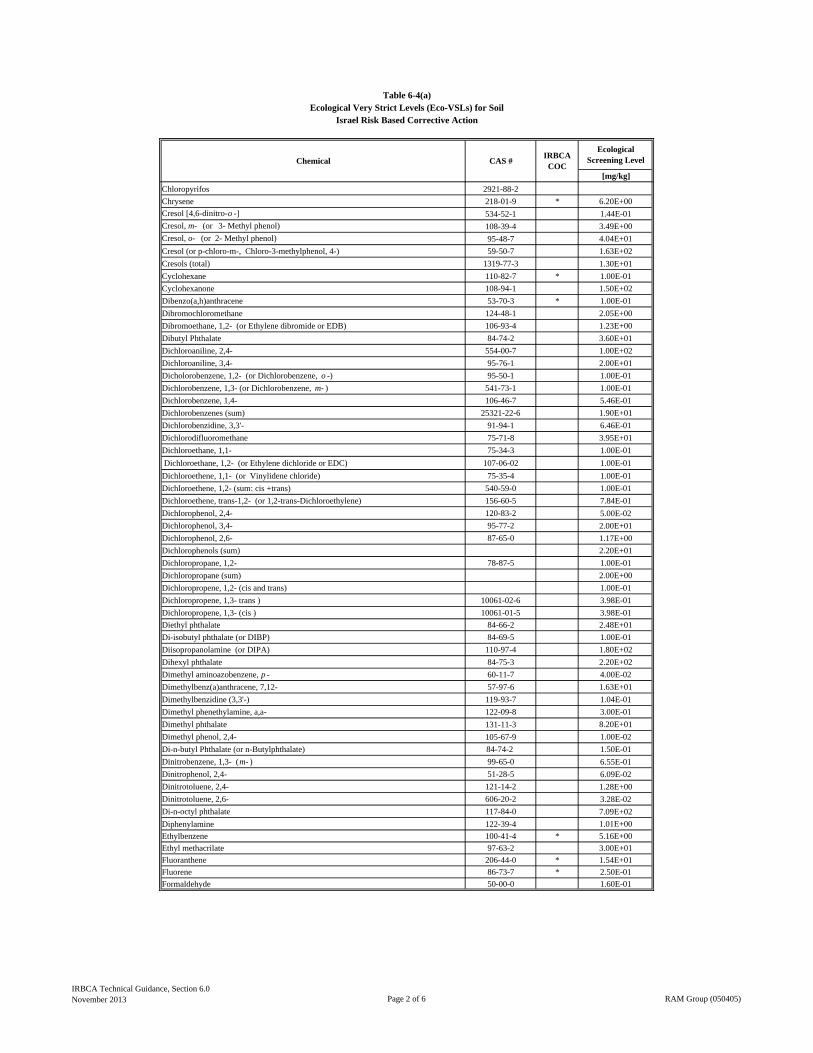
[mg/kg]
Table 6-4(a)Ecological Very Strict Levels (Eco-VSLs) for Soil
Israel Risk Based Corrective Action
Chemical CAS #IRBCA
COC
Ecological Screening Level
Chloropyrifos 2921-88-2
Chrysene 218-01-9 * 6.20E+00
Cresol [4,6-dinitro-o -] 534-52-1 1.44E-01
Cresol, m- (or 3- Methyl phenol) 108-39-4 3.49E+00
Cresol, o- (or 2- Methyl phenol) 95-48-7 4.04E+01
Cresol (or p-chloro-m-, Chloro-3-methylphenol, 4-) 59-50-7 1.63E+02
Cresols (total) 1319-77-3 1.30E+01
Cyclohexane 110-82-7 * 1.00E-01
Cyclohexanone 108-94-1 1.50E+02
Dibenzo(a,h)anthracene 53-70-3 * 1.00E-01
Dibromochloromethane 124-48-1 2.05E+00
Dibromoethane, 1,2- (or Ethylene dibromide or EDB) 106-93-4 1.23E+00
Dibutyl Phthalate 84-74-2 3.60E+01
Dichloroaniline, 2,4- 554-00-7 1.00E+02
Dichloroaniline, 3,4- 95-76-1 2.00E+01
Dicholorobenzene, 1,2- (or Dichlorobenzene, o -) 95-50-1 1.00E-01
Dichlorobenzene, 1,3- (or Dichlorobenzene, m- ) 541-73-1 1.00E-01
Dichlorobenzene, 1,4- 106-46-7 5.46E-01
Dichlorobenzenes (sum) 25321-22-6 1.90E+01
Dichlorobenzidine, 3,3'- 91-94-1 6.46E-01
Dichlorodifluoromethane 75-71-8 3.95E+01
Dichloroethane, 1,1- 75-34-3 1.00E-01
Dichloroethane, 1,2- (or Ethylene dichloride or EDC) 107-06-02 1.00E-01
Dichloroethene, 1,1- (or Vinylidene chloride) 75-35-4 1.00E-01
Dichloroethene, 1,2- (sum: cis +trans) 540-59-0 1.00E-01
Dichloroethene, trans-1,2- (or 1,2-trans-Dichloroethylene) 156-60-5 7.84E-01
Dichlorophenol, 2,4- 120-83-2 5.00E-02
Dichlorophenol, 3,4- 95-77-2 2.00E+01
Dichlorophenol, 2,6- 87-65-0 1.17E+00
Dichlorophenols (sum) 2.20E+01
Dichloropropane, 1,2- 78-87-5 1.00E-01
Dichloropropane (sum) 2.00E+00
Dichloropropene, 1,2- (cis and trans) 1.00E-01
Dichloropropene, 1,3- trans ) 10061-02-6 3.98E-01
Dichloropropene, 1,3- (cis ) 10061-01-5 3.98E-01
Diethyl phthalate 84-66-2 2.48E+01
Di-isobutyl phthalate (or DIBP) 84-69-5 1.00E-01
Diisopropanolamine (or DIPA) 110-97-4 1.80E+02
Dihexyl phthalate 84-75-3 2.20E+02
Dimethyl aminoazobenzene, p - 60-11-7 4.00E-02
Dimethylbenz(a)anthracene, 7,12- 57-97-6 1.63E+01
Dimethylbenzidine (3,3'-) 119-93-7 1.04E-01
Dimethyl phenethylamine, a,a- 122-09-8 3.00E-01
Dimethyl phthalate 131-11-3 8.20E+01
Dimethyl phenol, 2,4- 105-67-9 1.00E-02
Di-n-butyl Phthalate (or n-Butylphthalate) 84-74-2 1.50E-01
Dinitrobenzene, 1,3- (m- ) 99-65-0 6.55E-01
Dinitrophenol, 2,4- 51-28-5 6.09E-02
Dinitrotoluene, 2,4- 121-14-2 1.28E+00
Dinitrotoluene, 2,6- 606-20-2 3.28E-02
Di-n-octyl phthalate 117-84-0 7.09E+02
Diphenylamine 122-39-4 1.01E+00
Ethylbenzene 100-41-4 * 5.16E+00
Ethyl methacrilate 97-63-2 3.00E+01
Fluoranthene 206-44-0 * 1.54E+01
Fluorene 86-73-7 * 2.50E-01
Formaldehyde 50-00-0 1.60E-01
IRBCA Technical Guidance, Section 6.0November 2013 Page 2 of 6 RAM Group (050405)
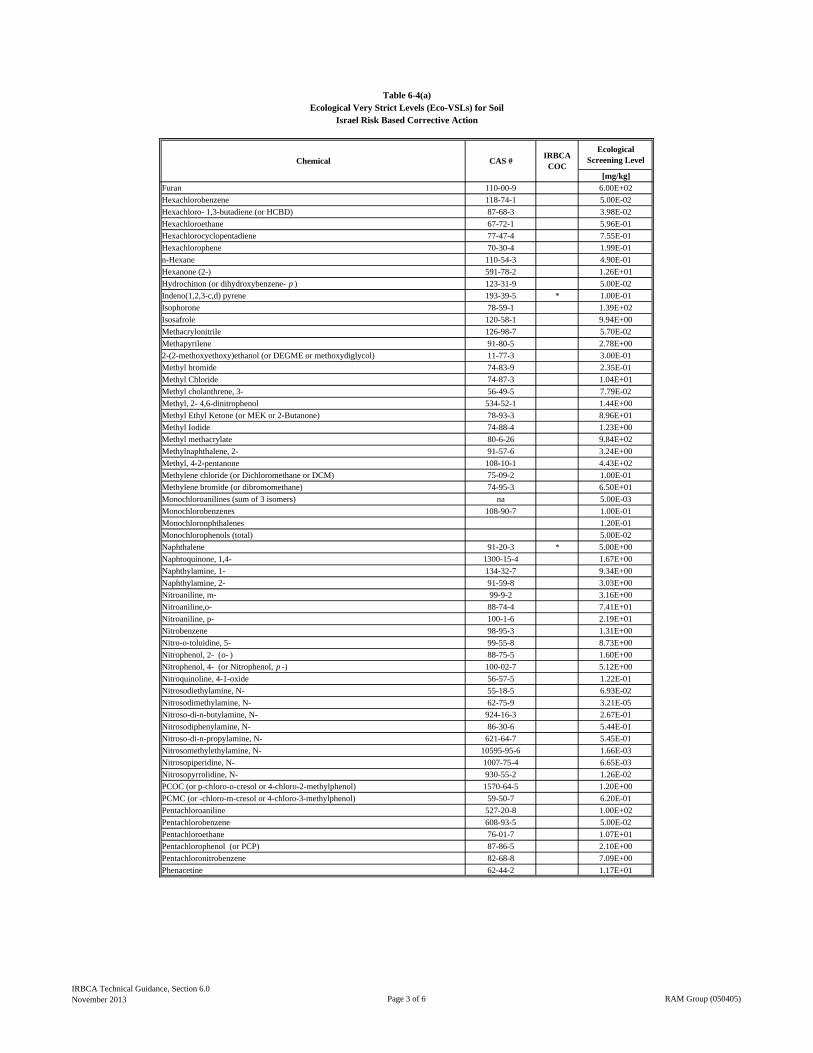
[mg/kg]
Table 6-4(a)Ecological Very Strict Levels (Eco-VSLs) for Soil
Israel Risk Based Corrective Action
Chemical CAS #IRBCA
COC
Ecological Screening Level
Furan 110-00-9 6.00E+02
Hexachlorobenzene 118-74-1 5.00E-02
Hexachloro- 1,3-butadiene (or HCBD) 87-68-3 3.98E-02
Hexachloroethane 67-72-1 5.96E-01
Hexachlorocyclopentadiene 77-47-4 7.55E-01
Hexachlorophene 70-30-4 1.99E-01
n-Hexane 110-54-3 4.90E-01
Hexanone (2-) 591-78-2 1.26E+01
Hydrochinon (or dihydroxybenzene- p ) 123-31-9 5.00E-02
Indeno(1,2,3-c,d) pyrene 193-39-5 * 1.00E-01
Isophorone 78-59-1 1.39E+02
Isosafrole 120-58-1 9.94E+00
Methacrylonitrile 126-98-7 5.70E-02
Methapyrilene 91-80-5 2.78E+00
2-(2-methoxyethoxy)ethanol (or DEGME or methoxydiglycol) 11-77-3 3.00E-01
Methyl bromide 74-83-9 2.35E-01
Methyl Chloride 74-87-3 1.04E+01
Methyl cholanthrene, 3- 56-49-5 7.79E-02
Methyl, 2- 4,6-dinitrophenol 534-52-1 1.44E+00
Methyl Ethyl Ketone (or MEK or 2-Butanone) 78-93-3 8.96E+01
Methyl Iodide 74-88-4 1.23E+00
Methyl methacrylate 80-6-26 9.84E+02
Methylnaphthalene, 2- 91-57-6 3.24E+00
Methyl, 4-2-pentanone 108-10-1 4.43E+02
Methylene chloride (or Dichloromethane or DCM) 75-09-2 1.00E-01
Methylene bromide (or dibromomethane) 74-95-3 6.50E+01
Monochloroanilines (sum of 3 isomers) na 5.00E-03
Monochlorobenzenes 108-90-7 1.00E-01
Monochloronphthalenes 1.20E-01
Monochlorophenols (total) 5.00E-02
Naphthalene 91-20-3 * 5.00E+00
Naphtoquinone, 1,4- 1300-15-4 1.67E+00
Naphthylamine, 1- 134-32-7 9.34E+00
Naphthylamine, 2- 91-59-8 3.03E+00
Nitroaniline, m- 99-9-2 3.16E+00
Nitroaniline,o- 88-74-4 7.41E+01
Nitroaniline, p- 100-1-6 2.19E+01
Nitrobenzene 98-95-3 1.31E+00
Nitro-o-toluidine, 5- 99-55-8 8.73E+00
Nitrophenol, 2- (o- ) 88-75-5 1.60E+00
Nitrophenol, 4- (or Nitrophenol, p -) 100-02-7 5.12E+00
Nitroquinoline, 4-1-oxide 56-57-5 1.22E-01
Nitrosodiethylamine, N- 55-18-5 6.93E-02
Nitrosodimethylamine, N- 62-75-9 3.21E-05
Nitroso-di-n-butylamine, N- 924-16-3 2.67E-01
Nitrosodiphenylamine, N- 86-30-6 5.44E-01
Nitroso-di-n-propylamine, N- 621-64-7 5.45E-01
Nitrosomethylethylamine, N- 10595-95-6 1.66E-03
Nitrosopiperidine, N- 1007-75-4 6.65E-03
Nitrosopyrrolidine, N- 930-55-2 1.26E-02
PCOC (or p-chloro-o-cresol or 4-chloro-2-methylphenol) 1570-64-5 1.20E+00
PCMC (or -chloro-m-cresol or 4-chloro-3-methylphenol) 59-50-7 6.20E-01
Pentachloroaniline 527-20-8 1.00E+02
Pentachlorobenzene 608-93-5 5.00E-02
Pentachloroethane 76-01-7 1.07E+01
Pentachlorophenol (or PCP) 87-86-5 2.10E+00
Pentachloronitrobenzene 82-68-8 7.09E+00
Phenacetine 62-44-2 1.17E+01
IRBCA Technical Guidance, Section 6.0November 2013 Page 3 of 6 RAM Group (050405)
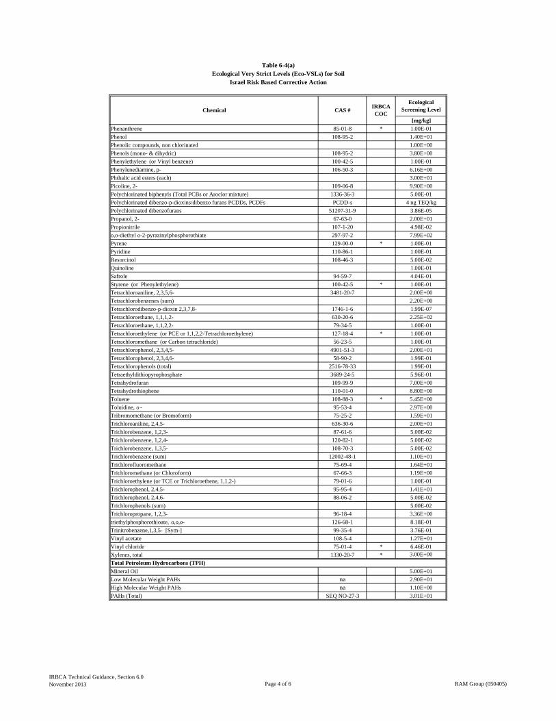
[mg/kg]
Table 6-4(a)Ecological Very Strict Levels (Eco-VSLs) for Soil
Israel Risk Based Corrective Action
Chemical CAS #IRBCA
COC
Ecological Screening Level
Phenanthrene 85-01-8 * 1.00E-01
Phenol 108-95-2 1.40E+01
Phenolic compounds, non chlorinated 1.00E+00
Phenols (mono- & dihydric) 108-95-2 3.80E+00
Phenylethylene (or Vinyl benzene) 100-42-5 1.00E-01
Phenylenediamine, p- 106-50-3 6.16E+00
Phthalic acid esters (each) 3.00E+01
Picoline, 2- 109-06-8 9.90E+00
Polychlorinated biphenyls (Total PCBs or Aroclor mixture) 1336-36-3 5.00E-01
Polychlorinated dibenzo-p-dioxins/dibenzo furans PCDDs, PCDFs PCDD-s 4 ng TEQ/kg
Polychlorinated dibenzofurans 51207-31-9 3.86E-05
Propanol, 2- 67-63-0 2.00E+01
Propionitrile 107-1-20 4.98E-02
o,o-diethyl o-2-pyrazinylphosphorothiate 297-97-2 7.99E+02
Pyrene 129-00-0 * 1.00E-01
Pyridine 110-86-1 1.00E-01
Resorcinol 108-46-3 5.00E-02
Quinoline 1.00E-01
Safrole 94-59-7 4.04E-01
Styrene (or Phenylethylene) 100-42-5 * 1.00E-01
Tetrachloroaniline, 2,3,5,6- 3481-20-7 2.00E+00
Tetrachlorobenzenes (sum) 2.20E+00
Tetrachlorodibenzo-p-dioxin 2,3,7,8- 1746-1-6 1.99E-07
Tetrachloroethane, 1,1,1,2- 630-20-6 2.25E+02
Tetrachloroethane, 1,1,2,2- 79-34-5 1.00E-01
Tetrachloroethylene (or PCE or 1,1,2,2-Tetrachloroethylene) 127-18-4 * 1.00E-01
Tetrachloromethane (or Carbon tetrachloride) 56-23-5 1.00E-01
Tetrachlorophenol, 2,3,4,5- 4901-51-3 2.00E+01
Tetrachlorophenol, 2,3,4,6- 58-90-2 1.99E-01
Tetrachlorophenols (total) 2516-78-33 1.99E-01
Tetraethyldithiopyrophosphate 3689-24-5 5.96E-01
Tetrahydrofuran 109-99-9 7.00E+00
Tetrahydrothiophene 110-01-0 8.80E+00
Toluene 108-88-3 * 5.45E+00
Toluidine, o - 95-53-4 2.97E+00
Tribromomethane (or Bromoform) 75-25-2 1.59E+01
Trichloroaniline, 2,4,5- 636-30-6 2.00E+01
Trichlorobenzene, 1,2,3- 87-61-6 5.00E-02
Trichlorobenzene, 1,2,4- 120-82-1 5.00E-02
Trichlorobenzene, 1,3,5- 108-70-3 5.00E-02
Trichlorobenzene (sum) 12002-48-1 1.10E+01
Trichlorofluoromethane 75-69-4 1.64E+01
Trichloromethane (or Chloroform) 67-66-3 1.19E+00
Trichloroethylene (or TCE or Trichloroethene, 1,1,2-) 79-01-6 1.00E-01
Trichlorophenol, 2,4,5- 95-95-4 1.41E+01
Trichlorophenol, 2,4,6- 88-06-2 5.00E-02
Trichlorophenols (sum) 5.00E-02
Trichloropropane, 1,2,3- 96-18-4 3.36E+00
triethylphosphorothioate, o,o,o- 126-68-1 8.18E-01
Trinitrobenzene,1,3,5- [Sym-] 99-35-4 3.76E-01
Vinyl acetate 108-5-4 1.27E+01
Vinyl chloride 75-01-4 * 6.46E-01
Xylenes, total 1330-20-7 * 3.00E+00
Mineral Oil 5.00E+01
Low Molecular Weight PAHs na 2.90E+01
High Molecular Weight PAHs na 1.10E+00
PAHs (Total) SEQ NO-27-3 3.01E+01
Total Petroleum Hydrocarbons (TPH)
IRBCA Technical Guidance, Section 6.0November 2013 Page 4 of 6 RAM Group (050405)
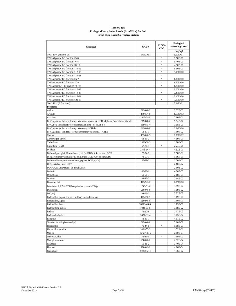
[mg/kg]
Table 6-4(a)Ecological Very Strict Levels (Eco-VSLs) for Soil
Israel Risk Based Corrective Action
Chemical CAS #IRBCA
COC
Ecological Screening Level
Total TPH (mineral oil) NOCAS 5.00E+01
TPH Aliphatic EC fraction >5-6 * 5.50E-01
TPH Aliphatic EC fraction >6-8 * 5.40E-01
TPH Aliphatic EC fraction >8-10 * 4.90E-01
TPH Aliphatic EC fraction >10-12 * 9.10E-01
TPH Aliphatic EC fraction >12-16 * 9.90E+00
TPH Aliphatic EC fraction >16-21 *
TPH Aromatic EC fraction >5-7 * 1.30E+00
TPH Aromatic EC fraction >7-8 * 1.50E+00
TPH Aromatic EC fraction >8-10 * 1.70E+00
TPH Aromatic EC fraction >10-12 * 2.00E+00
TPH Aromatic EC fraction >12-16 * 2.40E+00
TPH Aromatic EC fraction >16-21 * 3.10E+00
TPH Aromatic EC fraction >21-35 * 7.00E+00
Total TPH (S fractions) 3.14E+01
Aldrin 309-00-2 3.32E-03
Aramite 140-57-8 1.66E+02
Atrazine 1912-24-9 * 7.10E-01
BHC alpha (or hexacholorocyclohexane, alpha- or HCH, alpha or Benzohexachloride) 319-84-6 9.94E-02
BHC, beta (or hexacholorocyclohexane, beta- or HCH b-) 319-85-7 3.98E-03
BHC, delta (or hexacholorocyclohexane, HCH d-) 319-86-8 9.94E+00
BHC, gamma -Lindane (or hexacholorocyclohexane, HCH g-) 58-89-9 1.00E-02Captan 133-06-2 2.39E+02
Carbaryl (or Sevin) 63-25-2 4.50E-01
Carbofuran 1563-66-2 1.70E-02
Chlordane (total) 57-74-9 * 2.24E-01
Diallate 2303-16-4 4.52E-01
Dichlrodiphenyldichloroethane, p,p'- (or DDD, 4,4'- or sum DDD 72-54-8 7.58E-01
Dichlorodiphenyldichloroethene, p,p' (or DDE, 4,4'- or sum DDE) 72-55-9 5.96E-01
Dichlorodiphenyltrichloroethane, p,p' (or DDT, 4,4'- ) 50-29-3 3.50E-03
DDT (total) or sum DDT 2.10E-02
DDT/DDE/DDD (total) or Total DDTs 2.10E-02
Dieldrin 60-57-1 4.90E-03
Dimethoate 60-51-5 2.18E-01
Dinoseb 88-85-7 2.18E-02
Dioxane, 1,4 123-91-1 2.05E+00
Dioxin (or 2,3,7,8- TCDD equivalents, sum I-TEQ) 1746-01-6 1.99E-07
Disulfoton 298-04-4 1.99E-02
D (2,4-) 94-75-7 2.72E-02
Endosulfan (alpha + beta + sulfate) -mixed isomers 115-29-7 1.19E-01
Endosulfan, alpha 959-98-8 1.19E-01
Endosulfan, beta 33213-65-9 1.19E-01
Endosulfane sulfate 1031-07-8 3.58E-02
Endrin 72-20-8 * 1.01E-02
Endrin aldehyde 7421-93-4 1.05E-02
Famphur 52-85-7 4.97E-02
Guthion (or azinphos-methyl) 865-00-0 5.00E-06
Heptachlor 76-44-8 * 5.98E-03
Heptachlor epoxide 1024-57-3 1.52E-01
Maneb 12427-38-2 2.00E-03
Methoxychlor 72-43-5 * 1.99E-02
Methyl parathion 298-00-0 2.92E-04
Parathion 56-38-2 3.40E-04
Phorate 298-02-2 4.96E-04
Pronamide 23950-58-5 1.36E-02
Pesticides
IRBCA Technical Guidance, Section 6.0November 2013 Page 5 of 6 RAM Group (050405)

[mg/kg]
Table 6-4(a)Ecological Very Strict Levels (Eco-VSLs) for Soil
Israel Risk Based Corrective Action
Chemical CAS #IRBCA
COC
Ecological Screening Level
2,4,5-TP (or Silvex) 93-72-1 1.09E-01
Sulfolane (or Bondelane) 126-33-0 8.00E-01
Thiophene 108-88-3 1.00E-01
Toxaphene 8001-35-2 1.19E-01
Metals
Antimony 7440-36-0 2.00E+01
Arsenic 7440-38-2 * 1.80E+01
Arsenic V 7784-42-1 1.80E+01
Barium 7440-39-3 5.00E+02
Beryllium 7440-41-7 2.10E+01
Cadmium 7440-43-9 * 3.60E-01
Chromium (III) 16065-83-1 * 3.40E+01
Chromium (IV) 18540-29-9 7.80E+01
Chromium (total) 7440-47-3 1.30E+02
Cobalt 7440-48-4 4.00E+01
Copper 7440-50-8 * 7.00E+01
Lead 7439-92-1 * 5.60E+01
Mercury (total) 7439-97-6 * 1.00E+00
Molibdenum 7439-98-7 2.00E+00
Nickel 7440-02-0 * 1.30E+02
Organo-tin compounds (sum) 2.50E+00
Selenium 7782-49-2 * 1.00E+00
Silver 7440-22-4 * 4.20E+00
Thalium 7440-28-0 1.00E+00
Tin (total) 7440-31-5 5.00E+00
Tributyltin oxide 56-35-9 1.00E-03
Uranium, inorganic 7440-61-1 2.30E+01
Vanadium 7440-62-2 1.30E+02
Zinc 7440-66-6 * 1.20E+02
Inorganics
Cyanide, free (total) 57-12-5 * 1.00E+00
Cyanide (total complex) 5.00E+00
Thiocyanates (total) 1.00E+00
Others
Methyl mercury 22967-92-6 1.58E-03
Notes:
Soil concentrations are presented on a dry weight basis.
Concentrations were obtained from the following sources:
US EPA RCRA Region V ESL
US EPA Eco-SSL (Background levels of metals taken into consideration) Canadian Environmental Quality Guidelines CCME -Agricultural or soil and Food Ingestion
Dutch Target value 2009
Australian Dept. of Environment and Conservation: Assessment Levels for Soil, sediment and water, February 2010, Version 4, Revision 1
NOAA SQuiRTs
IRBCA Technical Guidance, Section 6.0November 2013 Page 6 of 6 RAM Group (050405)
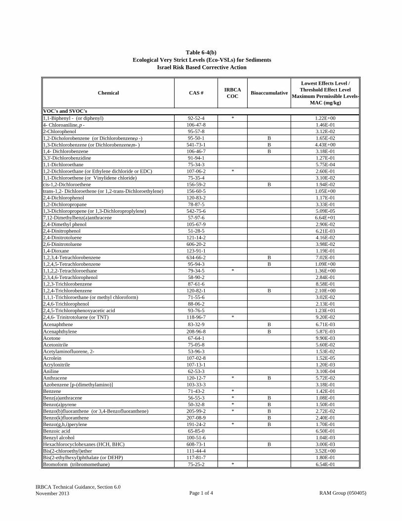
1,1-Biphenyl - (or diphenyl) 92-52-4 * 1.22E+004- Chloroaniline, p - 106-47-8 1.46E-012-Chlorophenol 95-57-8 3.12E-021,2-Dicholorobenzene (or Dichlorobenzene, o -) 95-50-1 B 1.65E-021,3-Dichlorobenzene (or Dichlorobenzene, m- ) 541-73-1 B 4.43E+001,4- Dichlorobenzene 106-46-7 B 3.18E-013,3'-Dichlorobenzidine 91-94-1 1.27E-011,1-Dichloroethane 75-34-3 5.75E-041,2-Dichloroethane (or Ethylene dichloride or EDC) 107-06-2 * 2.60E-011,1-Dichloroethene (or Vinylidene chloride) 75-35-4 3.10E-02cis-1,2-Dichloroethene 156-59-2 B 1.94E-02trans-1,2- Dichloroethene (or 1,2-trans-Dichloroethylene) 156-60-5 1.05E+002,4-Dichlorophenol 120-83-2 1.17E-011,2-Dichloropropane 78-87-5 3.33E-011,3-Dichloropropene (or 1,3-Dichloroproplylene) 542-75-6 5.09E-057,12-Dimethylbenz(a)anthracene 57-97-6 6.64E+012,4-Dimethyl phenol 105-67-9 2.90E-022,4-Dinitrophenol 51-28-5 6.21E-032,4-Dinitrotoluene 121-14-2 4.16E-022,6-Dinitrotoluene 606-20-2 3.98E-021,4-Dioxane 123-91-1 1.19E-011,2,3,4-Tetrachlorobenzene 634-66-2 B 7.02E-011,2,4,5-Tetrachlorobenzene 95-94-3 B 1.09E+001,1,2,2-Tetrachloroethane 79-34-5 * 1.36E+002,3,4,6-Tetrachlorophenol 58-90-2 2.84E-011,2,3-Trichlorobenzene 87-61-6 8.58E-011,2,4-Trichlorobenzene 120-82-1 B 2.10E+001,1,1-Trichloroethane (or methyl chloroform) 71-55-6 3.02E-022,4,6-Trichlorophenol 88-06-2 2.13E-012,4,5-Trichlorophenoxyacetic acid 93-76-5 1.23E+012,4,6- Trinitrotoluene (or TNT) 118-96-7 * 9.20E-02
Acenaphthene 83-32-9 B 6.71E-03Acenaphthylene 208-96-8 B 5.87E-03Acetone 67-64-1 9.90E-03Acetonitrile 75-05-8 5.60E-02Acetylaminofluorene, 2- 53-96-3 1.53E-02Acrolein 107-02-8 1.52E-05Acrylonitrile 107-13-1 1.20E-03Aniline 62-53-3 3.10E-04Anthracene 120-12-7 * B 5.72E-02Azobenzene [p-(dimethylamino)] 103-33-3 3.18E-01Benzene 71-43-2 * 1.42E-01Benz(a)anthracene 56-55-3 * B 1.08E-01Benzo(a)pyrene 50-32-8 * B 1.50E-01Benzo(b)fluoranthene (or 3,4-Benzofluoranthene) 205-99-2 * B 2.72E-02Benzo(k)fluoranthene 207-08-9 B 2.40E-01Benzo(g,h,i)perylene 191-24-2 * B 1.70E-01Benzoic acid 65-85-0 6.50E-01Benzyl alcohol 100-51-6 1.04E-03Hexachlorocyclohexanes (HCH, BHC) 608-73-1 B 3.00E-03Bis(2-chloroethyl)ether 111-44-4 3.52E+00Bis(2-ethylhexyl)phthalate (or DEHP) 117-81-7 1.80E-01Bromoform (tribromomethane) 75-25-2 * 6.54E-01
Table 6-4(b)Ecological Very Strict Levels (Eco-VSLs) for Sediments
Israel Risk Based Corrective Action
Lowest Effects Level / Threshold Effect Level
Maximum Permissible Levels-MAC (mg/kg)
VOC's and SVOC's
Chemical CAS #IRBCA COC
Bioaccumulative
IRBCA Technical Guidance, Section 6.0November 2013 Page 1 of 4 RAM Group (050405)
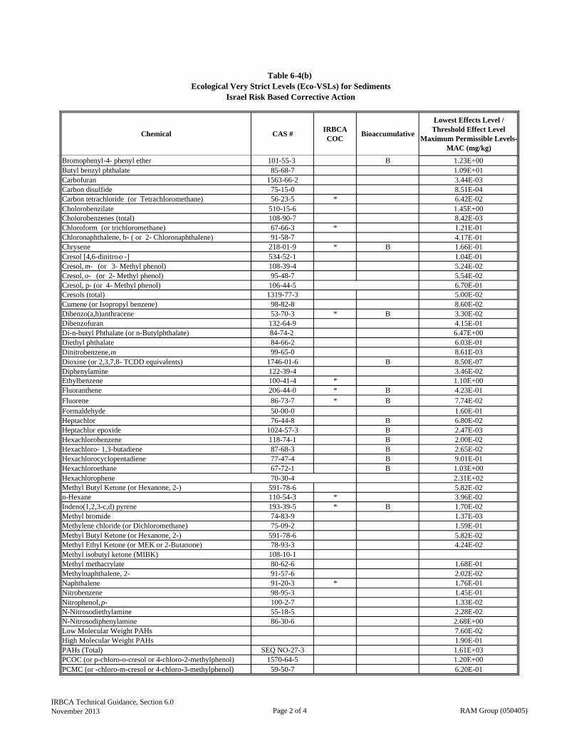
Table 6-4(b)Ecological Very Strict Levels (Eco-VSLs) for Sediments
Israel Risk Based Corrective Action
Lowest Effects Level / Threshold Effect Level
Maximum Permissible Levels-MAC (mg/kg)
Chemical CAS #IRBCA COC
Bioaccumulative
Bromophenyl-4- phenyl ether 101-55-3 B 1.23E+00Butyl benzyl phthalate 85-68-7 1.09E+01Carbofuran 1563-66-2 3.44E-03Carbon disulfide 75-15-0 8.51E-04Carbon tetrachloride (or Tetrachloromethane) 56-23-5 * 6.42E-02Cholorobenzilate 510-15-6 1.45E+00Cholorobenzenes (total) 108-90-7 8.42E-03Chloroform (or trichloromethane) 67-66-3 * 1.21E-01Chloronaphthalene, b- ( or 2- Chloronaphthalene) 91-58-7 4.17E-01Chrysene 218-01-9 * B 1.66E-01Cresol [4,6-dinitro-o -] 534-52-1 1.04E-01Cresol, m- (or 3- Methyl phenol) 108-39-4 5.24E-02Cresol, o- (or 2- Methyl phenol) 95-48-7 5.54E-02Cresol, p- (or 4- Methyl phenol) 106-44-5 6.70E-01Cresols (total) 1319-77-3 5.00E-02Cumene (or Isopropyl benzene) 98-82-8 8.60E-02Dibenzo(a,h)anthracene 53-70-3 * B 3.30E-02Dibenzofuran 132-64-9 4.15E-01Di-n-butyl Phthalate (or n-Butylphthalate) 84-74-2 6.47E+00Diethyl phthalate 84-66-2 6.03E-01Dinitrobenzene, m 99-65-0 8.61E-03Dioxine (or 2,3,7,8- TCDD equivalents) 1746-01-6 B 8.50E-07Diphenylamine 122-39-4 3.46E-02Ethylbenzene 100-41-4 * 1.10E+00Fluoranthene 206-44-0 * B 4.23E-01
Fluorene 86-73-7 * B 7.74E-02Formaldehyde 50-00-0 1.60E-01Heptachlor 76-44-8 B 6.80E-02Heptachlor epoxide 1024-57-3 B 2.47E-03Hexachlorobenzene 118-74-1 B 2.00E-02Hexachloro- 1,3-butadiene 87-68-3 B 2.65E-02Hexachlorocyclopentadiene 77-47-4 B 9.01E-01Hexachloroethane 67-72-1 B 1.03E+00Hexachlorophene 70-30-4 2.31E+02Methyl Butyl Ketone (or Hexanone, 2-) 591-78-6 5.82E-02n-Hexane 110-54-3 * 3.96E-02Indeno(1,2,3-c,d) pyrene 193-39-5 * B 1.70E-02Methyl bromide 74-83-9 1.37E-03Methylene chloride (or Dichloromethane) 75-09-2 1.59E-01Methyl Butyl Ketone (or Hexanone, 2-) 591-78-6 5.82E-02Methyl Ethyl Ketone (or MEK or 2-Butanone) 78-93-3 4.24E-02Methyl isobutyl ketone (MIBK) 108-10-1Methyl methacrylate 80-62-6 1.68E-01Methylnaphthalene, 2- 91-57-6 2.02E-02Naphthalene 91-20-3 * 1.76E-01Nitrobenzene 98-95-3 1.45E-01Nitrophenol, p- 100-2-7 1.33E-02N-Nitrosodiethylamine 55-18-5 2.28E-02N-Nitrosodiphenylamine 86-30-6 2.68E+00Low Molecular Weight PAHs 7.60E-02High Molecular Weight PAHs 1.90E-01PAHs (Total) SEQ NO-27-3 1.61E+03PCOC (or p-chloro-o-cresol or 4-chloro-2-methylphenol) 1570-64-5 1.20E+00PCMC (or -chloro-m-cresol or 4-chloro-3-methylphenol) 59-50-7 6.20E-01
IRBCA Technical Guidance, Section 6.0November 2013 Page 2 of 4 RAM Group (050405)
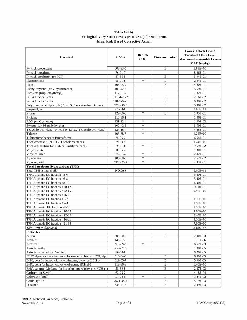
Table 6-4(b)Ecological Very Strict Levels (Eco-VSLs) for Sediments
Israel Risk Based Corrective Action
Lowest Effects Level / Threshold Effect Level
Maximum Permissible Levels-MAC (mg/kg)
Chemical CAS #IRBCA COC
Bioaccumulative
Pentachlorobenzene 608-93-5 B 8.89E+00Pentachloroethane 76-01-7 8.26E-01Pentachlorophenol (or PCP) 87-86-5 B 5.04E-01Phenanthrene 85-01-8 * B 2.04E-01Phenol 108-95-2 B 4.20E-01Phenylethylene (or Vinyl benzene) 100-42-5 5.59E-01Phthalate [bis(2-ethylhexyl)] 117-81-7 1.82E-01PCB (Aroclor 1221) 11104-28-2 B 2.16E-02PCB (Aroclor 1254) 11097-69-1 B 6.00E-02Polychlorinated biphenyls (Total PCBs or Aroclor mixture) 1336-36-3 B 5.98E-02Propanol, 2- 67-63-0 2.00E+01Pyrene 129-00-0 * B 1.95E-01Pyridine 110-86-1 1.06E-01RDX (or Cyclonite) 121-82-4 * 1.30E-02Styrene (or Phenylethylene) 100-42-5 * 5.59E-01Tetrachloroethylene (or PCE or 1,1,2,2-Tetrachloroethylene) 127-18-4 * 4.68E-01Toluene 108-88-3 * 1.22E+00Tribromomethane (or Bromoform) 75-25-2 6.54E-01Trichloroethane (or 1,1,2-Tricholoroethane) 79-00-5 1.24E+00Trichloroethylene (or TCE or Trichloroethene) 79-01-6 * 9.69E-02Vinyl acetate 108-5-4 1.30E-01Vinyl chloride 75-01-4 * 2.02E-01Xylene, m- 108-38-3 * 2.52E-02Xylenes, total 1330-20-7 * 4.33E-01Total Petroleum Hydrocarbons (TPH)Total TPH (mineral oil) NOCAS 5.00E+01TPH Aliphatic EC fraction >5-6 5.50E-01TPH Aliphatic EC fraction >6-8 5.40E-01TPH Aliphatic EC fraction >8-10 4.90E-01TPH Aliphatic EC fraction >10-12 9.10E-01TPH Aliphatic EC fraction >12-16 9.90E+00TPH Aliphatic EC fraction >16-21TPH Aromatic EC fraction >5-7 1.30E+00TPH Aromatic EC fraction >7-8 1.50E+00TPH Aromatic EC fraction >8-10 1.70E+00TPH Aromatic EC fraction >10-12 2.00E+00TPH Aromatic EC fraction >12-16 2.40E+00TPH Aromatic EC fraction >16-21 3.10E+00TPH Aromatic EC fraction >21-35 7.00E+00Total TPH (S fractions) 3.14E+01PesticidesAldrin 309-00-2 B 2.00E-03Aramite 140-57-8 1.11E-06Atrazine 1912-24-9 * 6.62E-03Azinphos-ethyl 2642-71-9 1.80E-05Azinphos-methyl (or Guthion) 86-50-0 6.20E-05 BHC alpha (or hexacholorocyclohexane, alpha- or HCH, alph 319-84-6 B 6.00E-03BHC, beta (or hexacholorocyclohexane, beta- or HCH b-) 319-85-7 B 5.00E-03BHC, delta (or hexacholorocyclohexane, HCH d-) 319-86-8 B 6.40E+00BHC, gamma -Lindane (or hexacholorocyclohexane, HCH g-) 58-89-9 B 2.37E-03Carbaryl (or Sevin) 63-25-2 4.18E-04Chlordane (total) 57-74-9 * B 3.24E-03Chloropyrifos 2921-88-2 B 5.19E-03Diazinon 333-41-5 B 2.39E-03
IRBCA Technical Guidance, Section 6.0November 2013 Page 3 of 4 RAM Group (050405)
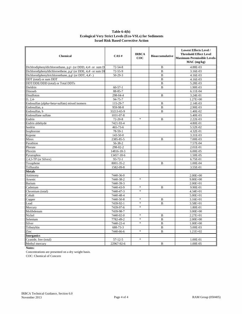
Table 6-4(b)Ecological Very Strict Levels (Eco-VSLs) for Sediments
Israel Risk Based Corrective Action
Lowest Effects Level / Threshold Effect Level
Maximum Permissible Levels-MAC (mg/kg)
Chemical CAS #IRBCA COC
Bioaccumulative
Dichlrodiphenyldichloroethane, p,p'- (or DDD, 4,4'- or sum DD 72-54-8 B 4.88E-03Dichlorodiphenyldichloroethene, p,p' (or DDE, 4,4'- or sum DD 72-55-9 B 3.16E-03Dichlorodiphenyltrichloroethane, p,p' (or DDT, 4,4'- ) 50-29-3 B 4.16E-03DDT (total) or sum DDT B 4.16E-03DDT/DDE/DDD (total) or Total DDTs B 5.28E-03Dieldrin 60-57-1 B 1.90E-03Dinoseb 88-85-7 6.11E-04Disulfoton 298-04-4 B 3.24E-01D, 2,4- 94-75-7 1.27E+00Endosulfan (alpha+beta+sulfate) mixed isomers 115-29-7 B 2.14E-03Endosulfan, a 959-98-8 B 2.90E-03Endosulfan, b 33213-65-9 B 1.40E-02Endosulfane sulfate 1031-07-8 5.40E-03Endrin 72-20-8 * B 2.22E-03Endrin aldehyde 7421-93-4 4.80E-01Isodrin 465-73-6 5.52E-02Isophorone 78-59-1 4.32E-01Kepone 143-50-0 3.31E-03Mirex 2385-85-5 B 7.00E-03Parathion 56-38-2 7.57E-04Phorate 298-02-2 2.01E-01Phoxim 14816-18-3 6.00E-05Pyrazophos 13457-18-6 1.50E-052,4,5-TP (or Silvex) 93-72-1 6.75E-01Toxaphene 8001-35-2 B 1.00E-04Trifluralin 1582-09-8 3.55E-01MetalsAntimony 7440-36-0 2.00E+00Arsenic 7440-38-2 * 9.80E+00Barium 7440-39-3 2.00E+01Cadmium 7440-43-9 * B 9.90E-01Chromium (total) 7440-47-3 * 4.34E+01Cobalt 7440-48-4 5.00E+01Copper 7440-50-8 * B 3.16E+01Lead 7439-92-1 * B 3.58E+01Mercury 7439-97-6 * 1.80E-01Molibdenum 7439-98-7 3.00E+00Nickel 7440-02-0 * B 2.27E+01Selenium 7782-49-2 * B 2.00E+00Silver 7440-22-4 * B 1.00E+00Tributyltin 688-73-3 B 5.00E-03Zinc 7440-66-6 * B 1.21E+02InorganicsCyanide, free (total) 57-12-5 * 1.00E-01Methyl mercury 22967-92-6 B 1.00E-05Notes:Concentrations are presented on a dry weight basis. COC: Chemical of Concern
IRBCA Technical Guidance, Section 6.0November 2013 Page 4 of 4 RAM Group (050405)

Pathway C/NC
Justification for Pathway C/NC
Boring(s)/Well(s)for Calc. Rep. Conc.
Pathway C/NC
Justification for Pathway C/NC Monitoring Points1
Surficial SoilCombined Pathway:Outdoor inhalation of vapor emissions and particulates, accidental ingestion, and dermal contact
1 1
Subsurface Soil
Indoor inhalation of vapor emissions
1 2
Indoor inhalation of vapor emissions
1 1
Incidental dermal contact 1 1
Domestic water use 1 1
Notes:C: Pathway is complete NC: Pathway is not complete 1: Data collected from these points used to estimate representative concentration
Table 7-1(a)Example Table to Document the Exposure Model for Resident
Groundwater (First Encounterd Zone)
Exposure PathwayCurrent Conditions Future Conditions
Israel Risk-Based Corrective Action
C
NC
C
NC
C
NC
C
NC
C
NC
C
NC
C
NC
C
NC
C
NC
C
NC
C
NC
C
NC
C
NC
IRBCA Technical Guidance, Section 7.0November 2013 RAM Group (050405)
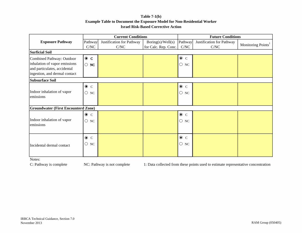
Pathway C/NC
Justification for Pathway C/NC
Boring(s)/Well(s)for Calc. Rep. Conc.
Pathway C/NC
Justification for Pathway C/NC Monitoring Points1
Surficial Soil
Combined Pathway: Outdoor inhalation of vapor emissions and particulates, accidental ingestion, and dermal contact
1 1
Subsurface Soil
Indoor inhalation of vapor emissions
1 1
Indoor inhalation of vapor emissions
1 1
Incidental dermal contact 1 1
Notes:C: Pathway is complete NC: Pathway is not complete 1: Data collected from these points used to estimate representative concentration
Table 7-1(b)Example Table to Document the Exposure Model for Non-Residential Worker
Groundwater (First Encounterd Zone)
Exposure PathwayCurrent Conditions Future Conditions
Israel Risk-Based Corrective Action
C
NC
C
NC
C
NC
C
NC
C
NC
C
NC
C
NC
C
NC
C
NC
C
NC
C
NC
IRBCA Technical Guidance, Section 7.0November 2013 RAM Group (050405)

Soil Upto Depth of Construction
Combined Pathway: Outdoor inhalation of vapor emissions and particulates, accidental ingestion, and dermal contact
1
Outdoor inhalation of vapor emissions
1
Incidental dermal contact 2
Notes:C: Pathway is complete NC: Pathway is not complete 1: Data collected from these points used to estimate representative concentration
Table 7-1(c)Example Table to Document the Exposure Model for Construction Worker
Exposure Pathway
Groundwater (First Encounterd Zone)
Pathway C/NC
Justification for Pathway C/NC Monitoring Points1
Israel Risk-Based Corrective Action
C
NC
C
NC
C
NC
IRBCA Technical Guidance, Section 7.0November 2013 RAM Group (050405)
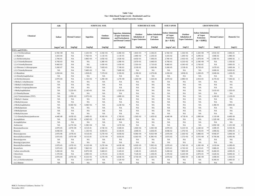
AIR
Indoor
[mg/m3-air] [mg/kg] [mg/kg] [mg/kg] [mg/L]
VOCs and SVOCs
1,1,1-Trichloroethane 6.76E+00 NA 1.52E+05 * 3.35E+03 * 3.28E+03 * 1.82E+03 * 2.24E-01 6.76E+02 1.33E+05 # 1.42E+00 ** 3.91E+02 2.00E-01 I
1,1-Biphenyl 5.41E-04 NA 7.76E+01 * 1.11E+01 1.11E+01 2.49E+02 * 2.23E-02 5.41E-02 1.20E+02 # 4.29E-02 1.84E-02 1.08E-03
1,1-Dichloroethylene 2.70E-01 NA 3.80E+03 * 1.05E+02 1.02E+02 4.45E+01 7.30E-03 2.70E+01 2.91E+03 # 1.87E-04 ** 1.30E+01 3.00E-02 I
1,2,3-Trimethylbenzene 6.76E-03 NA NA 1.28E+01 1.28E+01 2.67E+01 3.44E-03 6.76E-01 4.21E+02 # 2.19E+00 ** NA 1.35E-02
1,2,4-Trimethylbenzene 9.46E-03 NA NA 1.43E+01 1.43E+01 2.35E+01 2.71E-03 9.46E-01 4.24E+02 # 3.76E-02 NA 3.00E-03 I
1,2-Dibromo-3-chloropropane 5.26E-07 NA 7.76E-01 7.82E-03 7.74E-03 2.55E-02 1.56E-06 5.26E-05 2.53E-01 8.75E-05 1.67E-03 3.00E-04 I
1,3,5-Trimethylbenzene NA NA 7.60E+02 * NA 7.60E+02 * NA NA NA NA NA 3.00E-01 9.02E-02
1,3-Butadiene 1.05E-04 NA 1.83E-01 7.57E-02 5.35E-02 1.19E-02 2.27E-06 1.05E-02 3.85E-01 1.20E-05 ** 3.04E-04 1.63E-05
1,3-Dimethylnaphthalene NA NA NA NA NA NA NA NA NA NA NA NA
1,4-Dichlorobenzene 2.87E-04 NA 1.15E+02 * 1.29E+00 1.27E+00 1.26E+00 1.32E-04 2.87E-02 2.08E+01 2.91E-03 4.37E-02 7.50E-02 I
1-Methyl-2-ethylbenzene NA NA NA NA NA NA NA NA NA NA NA NA
1-Methyl-4-ethylbenzene NA NA NA NA NA NA NA NA NA NA NA NA
1-Methyl-4-isopropylbenzene NA NA NA NA NA NA NA NA NA NA NA NA
1-Methylnaphthalene NA 5.22E+01 2.14E+01 NA 1.52E+01 NA NA NA NA NA 5.01E-03 1.35E-03
2,3-Dimethylbutane NA NA NA NA NA NA NA NA NA NA NA NA
2,4,6-Trinitrotoluene (TNT) NA 2.05E+02 2.07E+01 NA 1.88E+01 NA NA NA NA NA 1.16E-01 2.12E-03
2-Methyl-1-butene NA NA NA NA NA NA NA NA NA NA NA NA
2-Methylchrysene NA NA NA NA NA NA NA NA NA NA NA NA
2-Methylnaphthalene NA 8.36E+02 * 3.04E+02 * NA 2.23E+02 * NA NA NA NA NA 1.38E-01 3.80E-02
2-Methylpentane NA NA NA NA NA NA NA NA NA NA NA NA
3-Methylpentane NA NA NA NA NA NA NA NA NA NA NA NA
6-Methylchrysene NA NA NA NA NA NA NA NA NA NA NA NA
7,12-Dimethylbenz(a)anthracene 4.44E-08 6.05E-03 2.48E-03 8.16E+01 * 1.76E-03 1.56E+02 * 1.43E-02 4.44E-06 4.73E-01 # 2.89E-04 1.31E-08 8.49E-09
Acenaphthene NA 1.25E+04 * 4.56E+03 * NA 3.34E+03 * NA NA NA NA NA 1.32E+00 4.70E-01
Acenaphthylene NA NA NA NA NA NA NA NA NA NA NA NA
Anthracene NA 6.27E+04 * 2.28E+04 * NA 1.67E+04 * NA NA NA NA NA 3.09E+00 # 1.52E+00 #
Benz(a)anthracene 2.87E-05 2.07E+00 * 8.51E-01 3.73E+01 * 5.94E-01 1.06E+04 * 1.03E+00 2.87E-03 + 9.21E+01 # 2.24E-02 ** 1.69E-05 8.55E-06
Benzene 4.04E-04 NA 1.13E+01 6.93E-01 6.53E-01 2.60E-01 4.43E-05 4.04E-02 1.37E+01 5.73E-03 ** 1.80E-02 5.00E-03 I
Benzo(a)pyrene 2.87E-06 2.07E-01 8.51E-02 5.27E+03 * 6.03E-02 8.58E+04 * 9.01E+00 * 2.87E-04 + 2.16E+02 # 5.88E-03 ** 9.94E-07 5.00E-04 I
Benzo(b)fluoranthene 2.87E-05 2.07E+00 * 8.51E-01 5.27E+04 * 6.03E-01 6.36E+05 * 6.39E+01 * 2.87E-03 + 1.57E+03 # 1.07E+00 # 9.79E-06 6.09E-06
Benzo(e)pyrene NA NA NA NA NA NA NA NA NA NA NA NA
Benzo(g,h,i)perylene NA NA NA NA NA NA NA NA NA NA NA NA
Benzo(k)fluoranthene 2.87E-05 2.07E+01 * 8.51E+00 * 5.27E+04 * 6.03E+00 * 6.92E+05 * 7.05E+01 * 2.87E-03 + 1.74E+03 # 1.20E+00 # 1.01E-04 6.28E-05
Bromoform 2.87E-03 2.49E+02 7.86E+01 1.56E+01 1.24E+01 1.87E+01 1.27E-03 2.87E-01 4.73E+02 4.11E-01 ** 2.88E-01 3.33E-03
Carbon tetrachloride 5.26E-04 NA 8.87E+00 5.66E-01 5.32E-01 1.34E-01 1.45E-05 5.26E-02 7.80E+00 5.94E-04 ** 8.46E-03 4.00E-03 I
Chloroform 1.37E-04 NA 2.00E+01 2.17E-01 2.15E-01 7.52E-02 1.10E-05 1.37E-02 6.22E+00 2.87E-03 ** 5.62E-02 8.00E-02 I
Chrysene 2.87E-04 2.07E+02 * 8.51E+01 * 5.27E+05 * 6.03E+01 * 4.73E+05 * 2.42E+01 * 2.87E-02 + 3.90E+03 # 1.34E+00 1.69E-03 1.01E-03
cis-1,2-Dichloroethylene NA NA 1.52E+02 NA 1.52E+02 NA NA NA NA NA 8.20E-01 5.00E-02 I
cis-2-Butene NA NA NA NA NA NA NA NA NA NA NA NA
SUBSURFACE SOIL
Outdoor Inhalation of
Vapor Emissions
[mg/kg]
SOILVAPOR GROUNDWATER
Outdoor Inhalation of
Vapor Emissions
[mg/m3-air] [mg/L][mg/kg]
Table 7-2(a)
Tier 1 Risk-Based Target Levels - Residential Land Use
Israel Risk-Based Corrective Action
Chemical
SURFICIAL SOIL
Dermal Contact IngestionOutdoor
InhalationDomestic Use
[mg/L] [mg/L]
Ingestion, Inhalation (Vapor Emissions and Particulates),
and Dermal Contact
Indoor Inhalation of Vapor Emissions
Indoor Inhalation of Vapor Emissions
(α = 0.01)
Indoor Inhalation of Vapor Emissions
(α = 0.001)
Dermal Contact
[mg/kg]
IRBCA Technical Guidance, Section 7.0November 2013 Page 1 of 3 RAM Group (050405)

AIR
Indoor
[mg/m3-air] [mg/kg] [mg/kg] [mg/kg] [mg/L]
SUBSURFACE SOIL
Outdoor Inhalation of
Vapor Emissions
[mg/kg]
SOILVAPOR GROUNDWATER
Outdoor Inhalation of
Vapor Emissions
[mg/m3-air] [mg/L][mg/kg]
Table 7-2(a)
Tier 1 Risk-Based Target Levels - Residential Land Use
Israel Risk-Based Corrective Action
Chemical
SURFICIAL SOIL
Dermal Contact IngestionOutdoor
InhalationDomestic Use
[mg/L] [mg/L]
Ingestion, Inhalation (Vapor Emissions and Particulates),
and Dermal Contact
Indoor Inhalation of Vapor Emissions
Indoor Inhalation of Vapor Emissions
(α = 0.01)
Indoor Inhalation of Vapor Emissions
(α = 0.001)
Dermal Contact
[mg/kg]
Coronene NA NA NA NA NA NA NA NA NA NA NA NA
Cyclohexane 8.11E+00 NA NA 2.93E+03 * 2.93E+03 * 1.16E+03 * 1.76E-01 8.11E+02 1.86E+04 # 1.32E+00 NA 1.62E+01
Dibenzo(a,h)anthracene 2.63E-06 2.07E-01 8.51E-02 4.83E+03 * 6.03E-02 6.76E+05 * 8.72E+01 * 2.63E-04 + 5.22E+02 # 4.56E-01 # 6.42E-07 4.09E-07
Dibenzothiophene NA NA NA NA NA NA NA NA NA NA NA NA
Ethylbenzene 1.26E-03 NA 5.65E+01 3.13E+00 2.97E+00 1.70E+00 2.22E-04 1.26E-01 4.36E+01 3.10E+00 ** 2.38E-02 3.00E-01 I
Ethylene dibromide (EDB) 5.26E-06 NA 3.11E-01 2.47E-02 2.29E-02 2.55E-02 2.09E-06 5.26E-04 6.95E-01 1.69E-03 ** 1.37E-03 5.00E-05 I
Ethylene dichloride (EDC) 1.21E-04 NA 6.82E+00 3.06E-01 2.93E-01 1.69E-01 2.75E-05 1.21E-02 8.61E+00 7.88E-03 ** 3.43E-02 1.80E-04
Fluoranthene NA 8.36E+03 * 3.04E+03 * NA 2.23E+03 * NA NA NA NA NA 2.92E-01 # 1.59E-01
Fluorene NA 8.36E+03 * 3.04E+03 * NA 2.23E+03 * NA NA NA NA NA 6.10E-01 2.59E-01
HMX (1,3,5,7-tetranitro-1,3,5,7- tetrazocane) NA 2.26E+05 * 3.80E+03 * NA 3.74E+03 * NA NA NA NA NA 9.91E+03 # 7.60E-01
Indene NA NA NA NA NA NA NA NA NA NA NA NA
Indeno(1,2,3-cd)pyrene 2.87E-05 2.07E+00 * 8.51E-01 * 5.27E+04 * 6.03E-01 * 3.82E+06 * 3.94E+02 * 2.87E-03 + 2.89E+03 # 2.02E+00 # 9.81E-06 6.11E-06
Isopropylbenzene 5.41E-01 NA 7.60E+03 * 6.47E+02 * 5.96E+02 * 8.48E+02 * 9.72E-02 5.41E+01 1.60E+04 # 1.15E+00 4.39E+00 5.29E-01
Methyl teriary butyl ether (MTBE) 1.21E-02 NA 3.45E+02 3.88E+01 3.49E+01 2.72E+01 3.89E-03 1.21E+00 1.41E+03 5.06E-01 2.29E+00 4.00E-02 I
Methylcyclohexane NA NA NA NA NA NA NA NA NA NA NA NA
Methylcyclopentane NA NA NA NA NA NA NA NA NA NA NA NA
Naphthalene 9.28E-05 4.18E+03 * 1.52E+03 * 1.75E+00 1.75E+00 7.21E+00 8.29E-04 9.28E-03 1.39E+01 1.67E-01 ** 1.13E+00 1.86E-04
n-Butylbenzene NA NA 3.80E+03 * NA 3.80E+03 * NA NA NA NA NA 6.52E-01 2.95E-01
n-Heptane NA NA NA NA NA NA NA NA NA NA NA NA
n-Hexane 9.46E-01 NA 4.56E+03 * 3.30E+02 * 3.08E+02 * 1.26E+02 1.76E-02 9.46E+01 2.03E+02 # 1.29E-02 2.65E+00 4.70E-01
n-Pentane 1.35E+00 NA NA 4.45E+02 * 4.45E+02 * 1.61E+02 2.51E-02 1.35E+02 3.72E+02 # 2.65E-02 NA 2.70E+00
n-Propylbenzene 1.35E+00 2.72E+04 * 7.60E+03 * 1.80E+03 * 1.38E+03 * 2.62E+03 * 3.00E-01 1.35E+02 4.29E+04 # 3.15E+00 2.87E+00 6.67E-01
Perylene NA NA NA NA NA NA NA NA NA NA NA NA
Phenanthrene NA NA NA NA NA NA NA NA NA NA NA NA
Pyrene NA 6.27E+03 * 2.28E+03 * NA 1.67E+03 * NA NA NA NA NA 1.59E-01 # 9.35E-02
RDX NA 1.19E+02 * 5.65E+00 NA 5.39E+00 NA NA NA NA NA 1.22E-01 5.90E-04
sec-Butylbenzene NA NA NA NA NA NA NA NA NA NA NA NA
Styrene 1.35E+00 NA 1.52E+04 * 2.41E+03 * 2.08E+03 * 4.70E+03 * 6.34E-01 1.35E+02 8.19E+04 # 8.89E-01 ** 1.62E+01 5.00E-02 I
tert-Butylbenzene NA NA NA NA NA NA NA NA NA NA NA NA
Tetrachloroethylene 1.21E-02 NA 2.96E+02 * 1.67E+01 1.58E+01 5.04E+00 4.83E-04 1.21E+00 2.84E+02 # 2.90E-02 ** 1.27E-01 1.00E-02 I
Toluene 6.76E+00 NA 6.08E+03 * 5.98E+03 * 3.02E+03 * 5.80E+03 * 8.58E-01 6.76E+02 2.33E+05 # 1.11E+00 ** 8.34E+00 7.00E-01 I
trans-1,2-Dichloroethylene 8.11E-02 NA 1.52E+03 * 5.32E+01 5.14E+01 3.83E+01 6.37E-03 8.11E+00 3.21E+03 4.86E-01 5.97E+00 5.00E-02 I
trans-2-Butene NA NA NA NA NA NA NA NA NA NA NA NA
Trichloroethylene 7.69E-04 NA 1.35E+01 1.00E+00 9.33E-01 2.86E-01 3.73E-05 7.69E-02 2.15E+01 1.91E-02 ** 1.98E-02 3.00E-02 I
Vinyl chloride 1.73E-04 NA 9.29E-02 1.19E-01 5.23E-02 1.98E-02 4.41E-06 1.73E-02 1.32E+00 2.02E-03 ** 7.34E-04 5.00E-04 I
Xylene (m) 1.35E-01 NA 1.52E+04 * 1.46E+02 * 1.45E+02 * 1.74E+02 * 2.26E-02 1.35E+01 4.98E+03 # 1.48E+00 ** 1.14E+01 1.00E+00 I
Xylene (o) 1.35E-01 NA 1.52E+04 * 1.70E+02 * 1.68E+02 * 2.35E+02 * 3.08E-02 1.35E+01 6.04E+03 # 6.38E-01 1.95E+01 1.00E+00 I
Xylene (p) 1.35E-01 NA 1.52E+04 * 1.49E+02 * 1.48E+02 * 1.80E+02 * 2.34E-02 1.35E+01 5.12E+03 # 4.79E-01 1.21E+01 2.42E-01
Xylenes (total) 1.35E-01 NA 1.52E+04 * 1.54E+02 * 1.52E+02 * 1.91E+02 * 3.08E-02 1.35E+01 5.03E+03 # 6.38E-01 2.07E+01 5.00E-01 I
IRBCA Technical Guidance, Section 7.0November 2013 Page 2 of 3 RAM Group (050405)
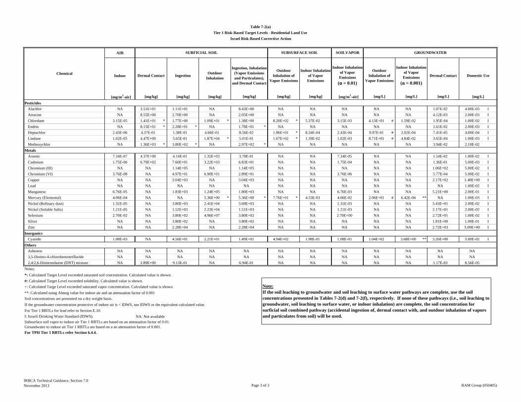
AIR
Indoor
[mg/m3-air] [mg/kg] [mg/kg] [mg/kg] [mg/L]
SUBSURFACE SOIL
Outdoor Inhalation of
Vapor Emissions
[mg/kg]
SOILVAPOR GROUNDWATER
Outdoor Inhalation of
Vapor Emissions
[mg/m3-air] [mg/L][mg/kg]
Table 7-2(a)
Tier 1 Risk-Based Target Levels - Residential Land Use
Israel Risk-Based Corrective Action
Chemical
SURFICIAL SOIL
Dermal Contact IngestionOutdoor
InhalationDomestic Use
[mg/L] [mg/L]
Ingestion, Inhalation (Vapor Emissions and Particulates),
and Dermal Contact
Indoor Inhalation of Vapor Emissions
Indoor Inhalation of Vapor Emissions
(α = 0.01)
Indoor Inhalation of Vapor Emissions
(α = 0.001)
Dermal Contact
[mg/kg]
Pesticides
Alachlor NA 3.51E+01 1.11E+01 NA 8.43E+00 NA NA NA NA NA 1.07E-02 4.00E-03 I
Atrazine NA 8.55E+00 2.70E+00 NA 2.05E+00 NA NA NA NA NA 4.12E-03 2.00E-03 I
Chlordane 3.15E-05 1.41E+01 * 1.77E+00 1.09E+01 * 1.38E+00 8.20E+02 * 5.37E-02 3.15E-03 4.13E+01 # 1.59E-02 1.95E-04 1.00E-02 I
Endrin NA 8.15E+01 * 2.28E+01 * NA 1.78E+01 * NA NA NA NA NA 1.61E-02 2.00E-03 I
Heptachlor 2.43E-06 4.37E-01 1.38E-01 4.66E-01 8.56E-02 1.96E+01 * 8.34E-04 2.43E-04 9.97E-01 # 2.02E-04 7.41E-05 4.00E-04 I
Lindane 1.02E-05 4.47E+00 5.65E-01 1.87E+04 * 5.01E-01 1.67E+02 * 1.39E-02 1.02E-03 8.71E+01 # 4.84E-02 3.65E-04 1.00E-03 I
Methoxychlor NA 1.36E+03 * 3.80E+02 * NA 2.97E+02 * NA NA NA NA NA 3.94E-02 2.10E-02
Metals
Arsenic 7.34E-07 4.37E+00 4.14E-01 1.35E+03 3.78E-01 NA NA 7.34E-05 NA NA 1.54E-02 1.00E-02 I
Cadmium 1.75E-06 6.79E+02 7.60E+01 3.22E+03 6.83E+01 NA NA 1.75E-04 NA NA 1.36E-01 5.00E-03 I
Chromium (III) NA NA 1.14E+05 NA 1.14E+05 NA NA NA NA NA 1.06E+02 5.00E-02 I
Chromium (VI) 3.76E-08 NA 4.97E+01 6.90E+01 2.89E+01 NA NA 3.76E-06 NA NA 5.77E-04 5.00E-02 I
Copper NA NA 3.04E+03 NA 3.04E+03 NA NA NA NA NA 2.17E+02 1.40E+00 I
Lead NA NA NA NA NA NA NA NA NA NA NA 1.00E-02 I
Manganese 6.76E-05 NA 1.83E+03 1.24E+05 1.80E+03 NA NA 6.76E-03 NA NA 5.21E+00 2.00E-01 I
Mercury (Elemental) 4.06E-04 NA NA 5.36E+00 * 5.36E+00 * 7.76E+01 * 4.53E-03 4.06E-02 2.06E+01 # 6.42E-04 ** NA 1.00E-03 I
Nickel (Refinary dust) 1.31E-05 NA 3.80E+03 2.41E+04 3.69E+03 NA NA 1.31E-03 NA NA 5.43E+01 2.00E-02 I
Nickel (Soluble Salts) 1.21E-05 NA 1.52E+03 2.23E+04 1.51E+03 NA NA 1.21E-03 NA NA 2.17E+01 2.00E-02 I
Selenium 2.70E-02 NA 3.80E+02 4.96E+07 3.80E+02 NA NA 2.70E+00 NA NA 2.72E+01 1.00E-02 I
Silver NA NA 3.80E+02 NA 3.80E+02 NA NA NA NA NA 1.81E+00 1.00E-01 I
Zinc NA NA 2.28E+04 NA 2.28E+04 NA NA NA NA NA 2.72E+03 5.00E+00 I
Inorganics
Cyanide 1.08E-03 NA 4.56E+01 2.21E+01 1.49E+01 4.94E+02 1.98E-01 1.08E-01 1.04E+02 3.68E+00 ** 3.26E+00 5.00E-02 I
Others
Asbestos NA NA NA NA NA NA NA NA NA NA NA NA
3,5-Dinitro-4-chlorobenzotrifluride NA NA NA NA NA NA NA NA NA NA NA NA
2,4/2,6-Dinitrotoluene (DNT) mixture NA 2.89E+00 9.13E-01 NA 6.94E-01 NA NA NA NA NA 1.17E-03 8.56E-05
Notes:
*: Calculated Target Level exceeded saturated soil concentration. Calculated value is shown.
#: Calculated Target Level exceeded solubility. Calculated value is shown.
+: Calculated Targe Level exceeded saturated vapor concentration. Calculated value is shown.
**: Calculated using Almog value for indoor air and an attenuation factor of 0.001
Soil concentrations are presented on a dry weight basis.
If the groundwater concentration protective of indoor air is < IDWS, use IDWS or the equivalent calculated value.
For Tier 1 RBTLs for lead refer to Section E.10.
I: Israeli Drinking Water Standard (IDWS). NA: Not availableSubsurface soil vapor to indoor air Tier 1 RBTLs are based on an attenuation factor of 0.01.Groundwater to indoor air Tier 1 RBTLs are based on a an attenuation factor of 0.001.
For TPH Tier 1 RBTLs refer Section 6.4.4.
Note:If the soil leaching to groundwater and soil leaching to surface water pathways are complete, use the soil concentrations presented in Tables 7-2(d) and 7-2(f), respectively. If none of these pathways (i.e., soil leaching to groundwater, soil leaching to surface water, or indoor inhalation) are complete, the soil concentration for surficial soil combined pathway (accidental ingestion of, dermal contact with, and outdoor inhalation of vapors and particulates from soil) will be used.
IRBCA Technical Guidance, Section 7.0November 2013 Page 3 of 3 RAM Group (050405)
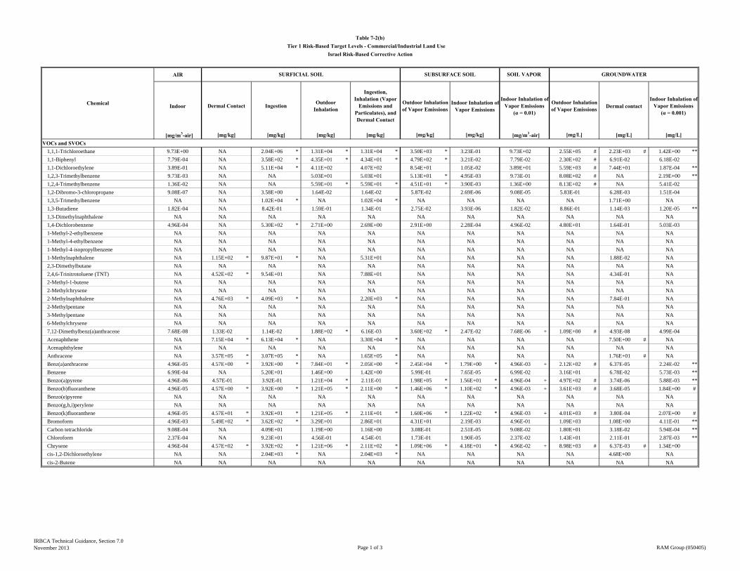
AIR
Indoor Indoor Inhalation of Vapor Emissions Dermal contact
[mg/m3-air] [mg/kg] [mg/kg] [mg/kg] [mg/kg] [mg/L] [mg/L]VOCs and SVOCs
1,1,1-Trichloroethane 9.73E+00 NA 2.04E+06 * 1.31E+04 * 1.31E+04 * 3.50E+03 * 3.23E-01 9.73E+02 2.55E+05 # 2.23E+03 # 1.42E+00 **
1,1-Biphenyl 7.79E-04 NA 3.58E+02 * 4.35E+01 * 4.34E+01 * 4.79E+02 * 3.21E-02 7.79E-02 2.30E+02 # 6.91E-02 6.18E-02
1,1-Dichloroethylene 3.89E-01 NA 5.11E+04 * 4.11E+02 4.07E+02 8.54E+01 1.05E-02 3.89E+01 5.59E+03 # 7.44E+01 1.87E-04 **
1,2,3-Trimethylbenzene 9.73E-03 NA NA 5.03E+01 5.03E+01 5.13E+01 * 4.95E-03 9.73E-01 8.08E+02 # NA 2.19E+00 **
1,2,4-Trimethylbenzene 1.36E-02 NA NA 5.59E+01 * 5.59E+01 * 4.51E+01 * 3.90E-03 1.36E+00 8.13E+02 # NA 5.41E-02
1,2-Dibromo-3-chloropropane 9.08E-07 NA 3.58E+00 1.64E-02 1.64E-02 5.87E-02 2.69E-06 9.08E-05 5.83E-01 6.28E-03 1.51E-04
1,3,5-Trimethylbenzene NA NA 1.02E+04 * NA 1.02E+04 * NA NA NA NA 1.71E+00 NA
1,3-Butadiene 1.82E-04 NA 8.42E-01 1.59E-01 1.34E-01 2.75E-02 3.93E-06 1.82E-02 8.86E-01 1.14E-03 1.20E-05 **
1,3-Dimethylnaphthalene NA NA NA NA NA NA NA NA NA NA NA
1,4-Dichlorobenzene 4.96E-04 NA 5.30E+02 * 2.71E+00 2.69E+00 2.91E+00 2.28E-04 4.96E-02 4.80E+01 1.64E-01 5.03E-03
1-Methyl-2-ethylbenzene NA NA NA NA NA NA NA NA NA NA NA
1-Methyl-4-ethylbenzene NA NA NA NA NA NA NA NA NA NA NA
1-Methyl-4-isopropylbenzene NA NA NA NA NA NA NA NA NA NA NA
1-Methylnaphthalene NA 1.15E+02 * 9.87E+01 * NA 5.31E+01 NA NA NA NA 1.88E-02 NA
2,3-Dimethylbutane NA NA NA NA NA NA NA NA NA NA NA
2,4,6-Trinitrotoluene (TNT) NA 4.52E+02 * 9.54E+01 NA 7.88E+01 NA NA NA NA 4.34E-01 NA
2-Methyl-1-butene NA NA NA NA NA NA NA NA NA NA NA
2-Methylchrysene NA NA NA NA NA NA NA NA NA NA NA
2-Methylnaphthalene NA 4.76E+03 * 4.09E+03 * NA 2.20E+03 * NA NA NA NA 7.84E-01 NA
2-Methylpentane NA NA NA NA NA NA NA NA NA NA NA
3-Methylpentane NA NA NA NA NA NA NA NA NA NA NA
6-Methylchrysene NA NA NA NA NA NA NA NA NA NA NA
7,12-Dimethylbenz(a)anthracene 7.68E-08 1.33E-02 1.14E-02 1.88E+02 * 6.16E-03 3.60E+02 * 2.47E-02 7.68E-06 + 1.09E+00 # 4.93E-08 4.99E-04
Acenaphthene NA 7.15E+04 * 6.13E+04 * NA 3.30E+04 * NA NA NA NA 7.50E+00 # NA
Acenaphthylene NA NA NA NA NA NA NA NA NA NA NA
Anthracene NA 3.57E+05 * 3.07E+05 * NA 1.65E+05 * NA NA NA NA 1.76E+01 # NA
Benz(a)anthracene 4.96E-05 4.57E+00 * 3.92E+00 * 7.84E+01 * 2.05E+00 * 2.45E+04 * 1.79E+00 * 4.96E-03 + 2.12E+02 # 6.37E-05 2.24E-02 **
Benzene 6.99E-04 NA 5.20E+01 1.46E+00 1.42E+00 5.99E-01 7.65E-05 6.99E-02 3.16E+01 6.78E-02 5.73E-03 **
Benzo(a)pyrene 4.96E-06 4.57E-01 3.92E-01 1.21E+04 * 2.11E-01 1.98E+05 * 1.56E+01 * 4.96E-04 + 4.97E+02 # 3.74E-06 5.88E-03 **
Benzo(b)fluoranthene 4.96E-05 4.57E+00 * 3.92E+00 * 1.21E+05 * 2.11E+00 * 1.46E+06 * 1.10E+02 * 4.96E-03 + 3.61E+03 # 3.68E-05 1.84E+00 #
Benzo(e)pyrene NA NA NA NA NA NA NA NA NA NA NA
Benzo(g,h,i)perylene NA NA NA NA NA NA NA NA NA NA NA
Benzo(k)fluoranthene 4.96E-05 4.57E+01 * 3.92E+01 * 1.21E+05 * 2.11E+01 * 1.60E+06 * 1.22E+02 * 4.96E-03 + 4.01E+03 # 3.80E-04 2.07E+00 #
Bromoform 4.96E-03 5.49E+02 * 3.62E+02 * 3.29E+01 2.86E+01 4.31E+01 2.19E-03 4.96E-01 1.09E+03 1.08E+00 4.11E-01 **
Carbon tetrachloride 9.08E-04 NA 4.09E+01 1.19E+00 1.16E+00 3.08E-01 2.51E-05 9.08E-02 1.80E+01 3.18E-02 5.94E-04 **
Chloroform 2.37E-04 NA 9.23E+01 4.56E-01 4.54E-01 1.73E-01 1.90E-05 2.37E-02 1.43E+01 2.11E-01 2.87E-03 **
Chrysene 4.96E-04 4.57E+02 * 3.92E+02 * 1.21E+06 * 2.11E+02 * 1.09E+06 * 4.18E+01 * 4.96E-02 + 8.98E+03 # 6.37E-03 # 1.34E+00
cis-1,2-Dichloroethylene NA NA 2.04E+03 * NA 2.04E+03 * NA NA NA NA 4.68E+00 NA
cis-2-Butene NA NA NA NA NA NA NA NA NA NA NA
Outdoor Inhalation of Vapor Emissions
[mg/L]
Dermal Contact
GROUNDWATER
Indoor Inhalation of Vapor Emissions
(α = 0.01)
Outdoor Inhalation
Ingestion, Inhalation (Vapor
Emissions and Particulates), and Dermal Contact
Indoor Inhalation of Vapor Emissions
(α = 0.001)
SOIL VAPOR SUBSURFACE SOIL
Outdoor Inhalation of Vapor EmissionsIngestion
Table 7-2(b)Tier 1 Risk-Based Target Levels - Commercial/Industrial Land Use
Israel Risk-Based Corrective Action
Chemical
SURFICIAL SOIL
[mg/kg] [mg/m3-air][mg/kg]
IRBCA Technical Guidance, Section 7.0November 2013 Page 1 of 3 RAM Group (050405)
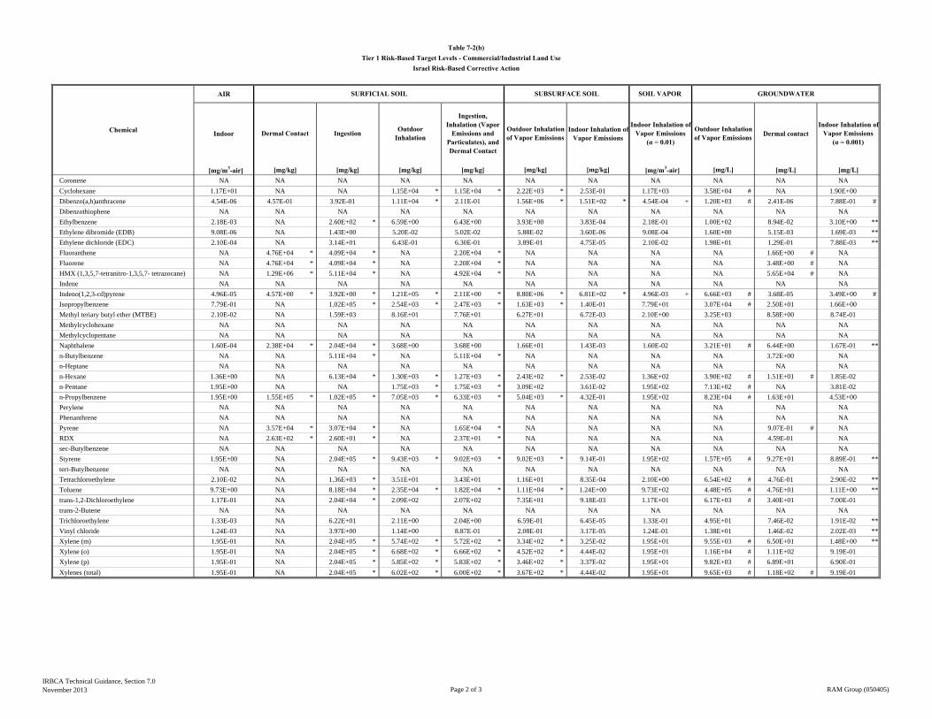
AIR
Indoor Indoor Inhalation of Vapor Emissions Dermal contact
[mg/m3-air] [mg/kg] [mg/kg] [mg/kg] [mg/kg] [mg/L] [mg/L]
Outdoor Inhalation of Vapor Emissions
[mg/L]
Dermal Contact
GROUNDWATER
Indoor Inhalation of Vapor Emissions
(α = 0.01)
Outdoor Inhalation
Ingestion, Inhalation (Vapor
Emissions and Particulates), and Dermal Contact
Indoor Inhalation of Vapor Emissions
(α = 0.001)
SOIL VAPOR SUBSURFACE SOIL
Outdoor Inhalation of Vapor EmissionsIngestion
Table 7-2(b)Tier 1 Risk-Based Target Levels - Commercial/Industrial Land Use
Israel Risk-Based Corrective Action
Chemical
SURFICIAL SOIL
[mg/kg] [mg/m3-air][mg/kg]Coronene NA NA NA NA NA NA NA NA NA NA NA
Cyclohexane 1.17E+01 NA NA 1.15E+04 * 1.15E+04 * 2.22E+03 * 2.53E-01 1.17E+03 3.58E+04 # NA 1.90E+00
Dibenzo(a,h)anthracene 4.54E-06 4.57E-01 3.92E-01 1.11E+04 * 2.11E-01 1.56E+06 * 1.51E+02 * 4.54E-04 + 1.20E+03 # 2.41E-06 7.88E-01 #
Dibenzothiophene NA NA NA NA NA NA NA NA NA NA NA
Ethylbenzene 2.18E-03 NA 2.60E+02 * 6.59E+00 6.43E+00 3.93E+00 3.83E-04 2.18E-01 1.00E+02 8.94E-02 3.10E+00 **
Ethylene dibromide (EDB) 9.08E-06 NA 1.43E+00 5.20E-02 5.02E-02 5.88E-02 3.60E-06 9.08E-04 1.60E+00 5.15E-03 1.69E-03 **
Ethylene dichloride (EDC) 2.10E-04 NA 3.14E+01 6.43E-01 6.30E-01 3.89E-01 4.75E-05 2.10E-02 1.98E+01 1.29E-01 7.88E-03 **
Fluoranthene NA 4.76E+04 * 4.09E+04 * NA 2.20E+04 * NA NA NA NA 1.66E+00 # NA
Fluorene NA 4.76E+04 * 4.09E+04 * NA 2.20E+04 * NA NA NA NA 3.48E+00 # NA
HMX (1,3,5,7-tetranitro-1,3,5,7- tetrazocane) NA 1.29E+06 * 5.11E+04 * NA 4.92E+04 * NA NA NA NA 5.65E+04 # NA
Indene NA NA NA NA NA NA NA NA NA NA NA
Indeno(1,2,3-cd)pyrene 4.96E-05 4.57E+00 * 3.92E+00 * 1.21E+05 * 2.11E+00 * 8.80E+06 * 6.81E+02 * 4.96E-03 + 6.66E+03 # 3.68E-05 3.49E+00 #
Isopropylbenzene 7.79E-01 NA 1.02E+05 * 2.54E+03 * 2.47E+03 * 1.63E+03 * 1.40E-01 7.79E+01 3.07E+04 # 2.50E+01 1.66E+00
Methyl teriary butyl ether (MTBE) 2.10E-02 NA 1.59E+03 8.16E+01 7.76E+01 6.27E+01 6.72E-03 2.10E+00 3.25E+03 8.58E+00 8.74E-01
Methylcyclohexane NA NA NA NA NA NA NA NA NA NA NA
Methylcyclopentane NA NA NA NA NA NA NA NA NA NA NA
Naphthalene 1.60E-04 2.38E+04 * 2.04E+04 * 3.68E+00 3.68E+00 1.66E+01 1.43E-03 1.60E-02 3.21E+01 # 6.44E+00 1.67E-01 **
n-Butylbenzene NA NA 5.11E+04 * NA 5.11E+04 * NA NA NA NA 3.72E+00 NA
n-Heptane NA NA NA NA NA NA NA NA NA NA NA
n-Hexane 1.36E+00 NA 6.13E+04 * 1.30E+03 * 1.27E+03 * 2.43E+02 * 2.53E-02 1.36E+02 3.90E+02 # 1.51E+01 # 1.85E-02
n-Pentane 1.95E+00 NA NA 1.75E+03 * 1.75E+03 * 3.09E+02 3.61E-02 1.95E+02 7.13E+02 # NA 3.81E-02
n-Propylbenzene 1.95E+00 1.55E+05 * 1.02E+05 * 7.05E+03 * 6.33E+03 * 5.04E+03 * 4.32E-01 1.95E+02 8.23E+04 # 1.63E+01 4.53E+00
Perylene NA NA NA NA NA NA NA NA NA NA NA
Phenanthrene NA NA NA NA NA NA NA NA NA NA NA
Pyrene NA 3.57E+04 * 3.07E+04 * NA 1.65E+04 * NA NA NA NA 9.07E-01 # NA
RDX NA 2.63E+02 * 2.60E+01 * NA 2.37E+01 * NA NA NA NA 4.59E-01 NA
sec-Butylbenzene NA NA NA NA NA NA NA NA NA NA NA
Styrene 1.95E+00 NA 2.04E+05 * 9.43E+03 * 9.02E+03 * 9.02E+03 * 9.14E-01 1.95E+02 1.57E+05 # 9.27E+01 8.89E-01 **
tert-Butylbenzene NA NA NA NA NA NA NA NA NA NA NA
Tetrachloroethylene 2.10E-02 NA 1.36E+03 * 3.51E+01 3.43E+01 1.16E+01 8.35E-04 2.10E+00 6.54E+02 # 4.76E-01 2.90E-02 **
Toluene 9.73E+00 NA 8.18E+04 * 2.35E+04 * 1.82E+04 * 1.11E+04 * 1.24E+00 9.73E+02 4.48E+05 # 4.76E+01 1.11E+00 **
trans-1,2-Dichloroethylene 1.17E-01 NA 2.04E+04 * 2.09E+02 2.07E+02 7.35E+01 9.18E-03 1.17E+01 6.17E+03 # 3.40E+01 7.00E-01
trans-2-Butene NA NA NA NA NA NA NA NA NA NA NA
Trichloroethylene 1.33E-03 NA 6.22E+01 2.11E+00 2.04E+00 6.59E-01 6.45E-05 1.33E-01 4.95E+01 7.46E-02 1.91E-02 **
Vinyl chloride 1.24E-03 NA 3.97E+00 1.14E+00 8.87E-01 2.08E-01 3.17E-05 1.24E-01 1.38E+01 1.46E-02 2.02E-03 **
Xylene (m) 1.95E-01 NA 2.04E+05 * 5.74E+02 * 5.72E+02 * 3.34E+02 * 3.25E-02 1.95E+01 9.55E+03 # 6.50E+01 1.48E+00 **
Xylene (o) 1.95E-01 NA 2.04E+05 * 6.68E+02 * 6.66E+02 * 4.52E+02 * 4.44E-02 1.95E+01 1.16E+04 # 1.11E+02 9.19E-01
Xylene (p) 1.95E-01 NA 2.04E+05 * 5.85E+02 * 5.83E+02 * 3.46E+02 * 3.37E-02 1.95E+01 9.82E+03 # 6.89E+01 6.90E-01
Xylenes (total) 1.95E-01 NA 2.04E+05 * 6.02E+02 * 6.00E+02 * 3.67E+02 * 4.44E-02 1.95E+01 9.65E+03 # 1.18E+02 # 9.19E-01
IRBCA Technical Guidance, Section 7.0November 2013 Page 2 of 3 RAM Group (050405)
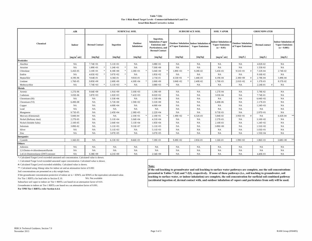
AIR
Indoor Indoor Inhalation of Vapor Emissions Dermal contact
[mg/m3-air] [mg/kg] [mg/kg] [mg/kg] [mg/kg] [mg/L] [mg/L]
Outdoor Inhalation of Vapor Emissions
[mg/L]
Dermal Contact
GROUNDWATER
Indoor Inhalation of Vapor Emissions
(α = 0.01)
Outdoor Inhalation
Ingestion, Inhalation (Vapor
Emissions and Particulates), and Dermal Contact
Indoor Inhalation of Vapor Emissions
(α = 0.001)
SOIL VAPOR SUBSURFACE SOIL
Outdoor Inhalation of Vapor EmissionsIngestion
Table 7-2(b)Tier 1 Risk-Based Target Levels - Commercial/Industrial Land Use
Israel Risk-Based Corrective Action
Chemical
SURFICIAL SOIL
[mg/kg] [mg/m3-air][mg/kg]Pesticides
Alachlor NA 7.74E+01 5.11E+01 NA 3.08E+01 NA NA NA NA 4.02E-02 NA
Atrazine NA 1.89E+01 * 1.24E+01 * NA 7.50E+00 NA NA NA NA 1.55E-02 NA
Chlordane 5.45E-05 3.10E+01 * 8.18E+00 * 2.28E+01 * 5.04E+00 * 1.89E+03 * 9.28E-02 5.45E-03 9.51E+01 # 7.32E-04 2.74E-02
Endrin NA 4.65E+02 * 3.07E+02 * NA 1.85E+02 * NA NA NA NA 9.16E-02 NA
Heptachlor 4.19E-06 9.64E-01 6.36E-01 9.81E-01 2.75E-01 4.53E+01 * 1.44E-03 4.19E-04 2.30E+00 # 2.78E-04 3.49E-04
Lindane 1.76E-05 9.85E+00 2.60E+00 4.30E+04 * 2.06E+00 3.84E+02 * 2.40E-02 1.76E-03 2.01E+02 # 1.37E-03 8.37E-02
Methoxychlor NA 7.74E+03 * 5.11E+03 * NA 3.08E+03 * NA NA NA NA 2.24E-01 # NA
Metals Arsenic 1.27E-06 9.64E+00 1.91E+00 3.10E+03 1.59E+00 NA NA 1.27E-04 NA 5.78E-02 NA
Cadmium 3.03E-06 3.87E+03 1.02E+03 7.41E+03 8.02E+02 NA NA 3.03E-04 NA 7.74E-01 NA
Chromium (III) NA NA 1.53E+06 NA 1.53E+06 NA NA NA NA 6.04E+02 NA
Chromium (VI) 6.49E-08 NA 5.72E+00 1.59E+02 5.52E+00 NA NA 6.49E-06 NA 2.17E-03 NA
Copper NA NA 4.09E+04 NA 4.09E+04 NA NA NA NA 1.24E+03 NA
Lead NA NA NA NA NA NA NA NA NA NA NA
Manganese 9.73E-05 NA 2.45E+04 2.38E+05 2.22E+04 NA NA 9.73E-03 NA 2.97E+01 NA
Mercury (Elemental) 5.84E-04 NA NA 2.10E+01 * 2.10E+01 * 1.49E+02 * 6.52E-03 5.84E-02 3.95E+01 # NA 6.42E-04 **
Nickel (Refinary dust) 2.27E-05 NA 5.11E+04 5.56E+04 4.21E+04 NA NA 2.27E-03 NA 3.10E+02 NA
Nickel (Soluble Salts) 2.10E-05 NA 2.04E+04 5.13E+04 1.95E+04 NA NA 2.10E-03 NA 1.24E+02 NA
Selenium 3.89E-02 NA 5.11E+03 9.53E+07 5.11E+03 NA NA 3.89E+00 NA 1.55E+02 NA
Silver NA NA 5.11E+03 NA 5.11E+03 NA NA NA NA 1.03E+01 NA
Zinc NA NA 3.07E+05 NA 3.07E+05 NA NA NA NA 1.55E+04 NA
InorganicsCyanide 1.56E-03 NA 6.13E+02 8.66E+01 7.59E+01 9.49E+02 2.85E-01 1.56E-01 1.99E+02 1.86E+01 3.68E+00 **
OthersAsbestos NA NA NA NA NA NA NA NA NA NA NA
3,5-Dinitro-4-chlorobenzotrifluride NA NA NA NA NA NA NA NA NA NA NA
2,4/2,6-Dinitrotoluene (DNT) mixture NA 6.38E+00 4.21E+00 NA 2.54E+00 NA NA NA NA 4.40E-03 NA
*: Calculated Target Level exceeded saturated soil concentration. Calculated value is shown.
+: Calculated Targe Level exceeded saturated vapor concentration. Calculated value is shown.
#: Calculated Target Level exceeded solubility. Calculated value is shown.
**: Calculated using Almog value for indoor air and an attenuation factor of 0.001
Soil concentrations are presented on a dry weight basis.
If the groundwater concentration protective of indoor air is < IDWS, use IDWS or the equivalent calculated value.
For Tier 1 RBTLs for lead refer to Section E.10. NA: Not available
Subsurface soil vapor to indoor air Tier 1 RBTLs are based on an attenuation factor of 0.01.
Groundwater to indoor air Tier 1 RBTLs are based on a an attenuation factor of 0.001.
For TPH Tier 1 RBTLs refer Section 6.4.4.
Note:If the soil leaching to groundwater and soil leaching to surface water pathways are complete, use the soil concentrations presented in Tables 7-2(d) and 7-2(f), respectively. If none of these pathways (i.e., soil leaching to groundwater, soil leaching to surface water, or indoor inhalation) are complete, the soil concentration for surficial soil combined pathway (accidental ingestion of, dermal contact with, and outdoor inhalation of vapors and particulates from soil) will be used.
IRBCA Technical Guidance, Section 7.0November 2013 Page 3 of 3 RAM Group (050405)
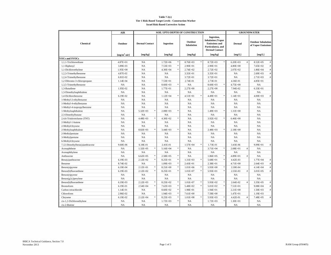
AIR
Outdoor DermalOutdoor Inhalation of Vapor Emissions
[mg/m3-air]
VOCs and SVOCs
1,1,1-Trichloroethane 4.87E+01 NA 1.72E+06 * 8.76E+03 * 8.72E+03 * 6.20E+03 # 8.52E+05 #
1,1-Biphenyl 3.89E-03 NA 7.53E+03 * 2.90E+01 2.90E+01 4.80E+00 7.65E+02 #
1,1-Dichloroethylene 1.95E+00 NA 4.30E+04 * 2.74E+02 2.72E+02 2.07E+02 1.86E+04 #
1,2,3-Trimethylbenzene 4.87E-02 NA NA 3.35E+01 3.35E+01 NA 2.69E+03 #
1,2,4-Trimethylbenzene 6.81E-02 NA NA 3.72E+01 3.72E+01 NA 2.71E+03 #
1,2-Dibromo-3-chloropropane 1.14E-04 NA 7.53E+01 2.74E-01 2.73E-01 4.36E-01 4.85E+01
1,3,5-Trimethylbenzene NA NA 8.60E+03 * NA 8.60E+03 * 4.75E+00 NA
1,3-Butadiene 1.95E-02 NA 1.77E+01 2.27E+00 2.27E+00 7.94E-02 6.33E+01
1,3-Dimethylnaphthalene NA NA NA NA NA NA NA
1,4-Dichlorobenzene 6.19E-02 NA 1.12E+04 * 4.51E+01 * 4.49E+01 * 1.14E+01 4.00E+03 #
1-Methyl-2-ethylbenzene NA NA NA NA NA NA NA
1-Methyl-4-ethylbenzene NA NA NA NA NA NA NA
1-Methyl-4-isopropylbenzene NA NA NA NA NA NA NA
1-Methylnaphthalene NA 5.32E+03 * 2.08E+03 * NA 1.49E+03 * 1.31E+00 NA
2,3-Dimethylbutane NA NA NA NA NA NA NA
2,4,6-Trinitrotoluene (TNT) NA 4.48E+03 * 4.30E+02 * NA 3.92E+02 * 6.46E+00 NA
2-Methyl-1-butene NA NA NA NA NA NA NA
2-Methylchrysene NA NA NA NA NA NA NA
2-Methylnaphthalene NA 8.82E+03 * 3.44E+03 * NA 2.48E+03 * 2.18E+00 NA
2-Methylpentane NA NA NA NA NA NA NA
3-Methylpentane NA NA NA NA NA NA NA
6-Methylchrysene NA NA NA NA NA NA NA
7,12-Dimethylbenz(a)anthracene 9.60E-06 6.18E-01 2.41E-01 1.57E+04 * 1.73E-01 3.43E-06 9.09E+01 #
Acenaphthene NA 1.32E+05 * 5.16E+04 * NA 3.71E+04 * 2.08E+01 # NA
Acenaphthylene NA NA NA NA NA NA NA
Anthracene NA 6.62E+05 * 2.58E+05 * NA 1.86E+05 * 4.89E+01 # NA
Benz(a)anthracene 6.19E-03 2.12E+02 * 8.25E+01 * 1.31E+03 * 5.68E+01 * 4.42E-03 1.77E+04 #
Benzene 8.74E-02 NA 1.09E+03 * 2.43E+01 2.38E+01 4.71E+00 2.64E+03 #
Benzo(a)pyrene 6.19E-04 2.12E+01 * 8.25E+00 * 1.01E+06 * 5.93E+00 * 2.59E-04 4.14E+04 #
Benzo(b)fluoranthene 6.19E-03 2.12E+02 * 8.25E+01 * 1.01E+07 * 5.93E+01 * 2.55E-03 # 3.01E+05 #
Benzo(e)pyrene NA NA NA NA NA NA NA
Benzo(g,h,i)perylene NA NA NA NA NA NA NA
Benzo(k)fluoranthene 6.19E-03 2.12E+03 * 8.25E+02 * 1.01E+07 * 5.93E+02 * 2.64E-02 # 3.35E+05 #
Bromoform 6.19E-01 2.54E+04 * 7.62E+03 * 5.48E+02 * 5.01E+02 * 7.51E+01 9.08E+04 #
Carbon tetrachloride 1.14E-01 NA 8.60E+02 * 1.98E+01 1.94E+01 2.21E+00 1.50E+03 #
Chloroform 2.96E-02 NA 1.94E+03 * 7.61E+00 7.58E+00 1.47E+01 1.19E+03
Chrysene 6.19E-02 2.12E+04 * 8.25E+03 * 1.01E+08 * 5.93E+03 * 4.42E-01 # 7.48E+05 #
cis-1,2-Dichloroethylene NA NA 1.72E+03 * NA 1.72E+03 * 1.30E+01 NA
cis-2-Butene NA NA NA NA NA NA NA
Table 7-2(c)
Tier 1 Risk-Based Target Levels - Construction Worker
Israel Risk-Based Corrective Action
Chemical
SOIL UPTO DEPTH OF CONSTRUCTION GROUNDWATER
Dermal Contact IngestionOutdoor
Inhalation
Ingestion, Inhalation (Vapor
Emissions and Particulates), and Dermal Contact
[mg/L] [mg/L][mg/kg] [mg/kg] [mg/kg] [mg/kg]
IRBCA Technical Guidance, Section 7.0November 2013 Page 1 of 3 RAM Group (050405)
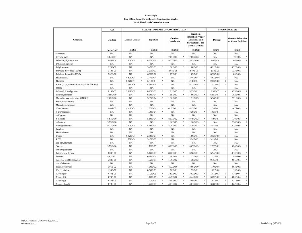
AIR
Outdoor DermalOutdoor Inhalation of Vapor Emissions
[mg/m3-air]
Table 7-2(c)
Tier 1 Risk-Based Target Levels - Construction Worker
Israel Risk-Based Corrective Action
Chemical
SOIL UPTO DEPTH OF CONSTRUCTION GROUNDWATER
Dermal Contact IngestionOutdoor
Inhalation
Ingestion, Inhalation (Vapor
Emissions and Particulates), and Dermal Contact
[mg/L] [mg/L][mg/kg] [mg/kg] [mg/kg] [mg/kg]
Coronene NA NA NA NA NA NA NA
Cyclohexane 5.84E+01 NA NA 7.65E+03 * 7.65E+03 * NA 1.19E+05 #
Dibenzo(a,h)anthracene 5.68E-04 2.12E+01 * 8.25E+00 * 9.27E+05 * 5.93E+00 * 1.67E-04 1.00E+05 #
Dibenzothiophene NA NA NA NA NA NA NA
Ethylbenzene 2.73E-01 NA 5.47E+03 * 1.10E+02 * 1.08E+02 * 6.21E+00 8.37E+03 #
Ethylene dibromide (EDB) 1.14E-03 NA 3.01E+01 8.67E-01 8.43E-01 3.58E-01 1.33E+02
Ethylene dichloride (EDC) 2.62E-02 NA 6.62E+02 1.07E+01 1.05E+01 8.95E+00 1.65E+03
Fluoranthene NA 8.82E+04 * 3.44E+04 * NA 2.48E+04 * 4.62E+00 # NA
Fluorene NA 8.82E+04 * 3.44E+04 * NA 2.48E+04 * 9.66E+00 # NA
HMX (1,3,5,7-tetranitro-1,3,5,7- tetrazocane) NA 2.39E+06 * 4.30E+04 * NA 4.23E+04 * 1.57E+05 # NA
Indene NA NA NA NA NA NA NA
Indeno(1,2,3-cd)pyrene 6.19E-03 2.12E+02 * 8.25E+01 * 1.01E+07 * 5.93E+01 * 2.56E-03 # 5.55E+05 #
Isopropylbenzene 3.89E+00 NA 8.60E+04 * 1.69E+03 * 1.66E+03 * 6.95E+01 # 1.02E+05 #
Methyl teriary butyl ether (MTBE) 2.62E+00 NA 3.35E+04 * 1.36E+03 1.31E+03 5.96E+02 2.71E+05 #
Methylcyclohexane NA NA NA NA NA NA NA
Methylcyclopentane NA NA NA NA NA NA NA
Naphthalene 2.00E-02 4.41E+04 * 1.72E+04 * 6.13E+01 * 6.13E+01 * 1.79E+01 2.67E+03 #
n-Butylbenzene NA NA 4.30E+04 * NA 4.30E+04 * 1.03E+01 NA
n-Heptane NA NA NA NA NA NA NA
n-Hexane 6.81E+00 NA 5.16E+04 * 8.63E+02 * 8.49E+02 * 4.19E+01 # 1.30E+03 #
n-Pentane 9.73E+00 NA NA 1.16E+03 * 1.16E+03 * NA 2.38E+03 #
n-Propylbenzene 9.73E+00 2.87E+05 * 8.60E+04 * 4.70E+03 * 4.39E+03 * 4.54E+01 2.74E+05 #
Perylene NA NA NA NA NA NA NA
Phenanthrene NA NA NA NA NA NA NA
Pyrene NA 6.62E+04 * 2.58E+04 * NA 1.86E+04 * 2.52E+00 # NA
RDX NA 1.22E+04 * 5.47E+02 * NA 5.24E+02 * 3.19E+01 NA
sec-Butylbenzene NA NA NA NA NA NA NA
Styrene 9.73E+00 NA 1.72E+05 * 6.29E+03 * 6.07E+03 * 2.57E+02 5.24E+05 #
tert-Butylbenzene NA NA NA NA NA NA NA
Tetrachloroethylene 3.89E-01 NA 5.16E+03 * 8.70E+01 * 8.56E+01 * 5.94E+00 8.10E+03 #
Toluene 4.87E+01 NA 6.88E+04 * 1.56E+04 * 1.27E+04 * 1.32E+02 1.49E+06 #
trans-1,2-Dichloroethylene 5.84E-01 NA 1.72E+04 * 1.39E+02 1.38E+02 9.45E+01 2.06E+04 #
trans-2-Butene NA NA NA NA NA NA NA
Trichloroethylene 1.95E-02 NA 4.30E+02 * 4.12E+00 4.08E+00 1.70E+00 4.83E+02
Vinyl chloride 1.55E-01 NA 8.36E+01 1.90E+01 1.55E+01 1.02E+00 1.15E+03
Xylene (m) 9.73E-01 NA 1.72E+05 * 3.83E+02 * 3.82E+02 * 1.81E+02 # 3.18E+04 #
Xylene (o) 9.73E-01 NA 1.72E+05 * 4.45E+02 * 4.44E+02 * 3.09E+02 # 3.86E+04 #
Xylene (p) 9.73E-01 NA 1.72E+05 * 3.90E+02 * 3.89E+02 * 1.91E+02 # 3.27E+04 #
Xylenes (total) 9.73E-01 NA 1.72E+05 * 4.01E+02 * 4.01E+02 * 3.28E+02 # 3.22E+04 #
IRBCA Technical Guidance, Section 7.0November 2013 Page 2 of 3 RAM Group (050405)
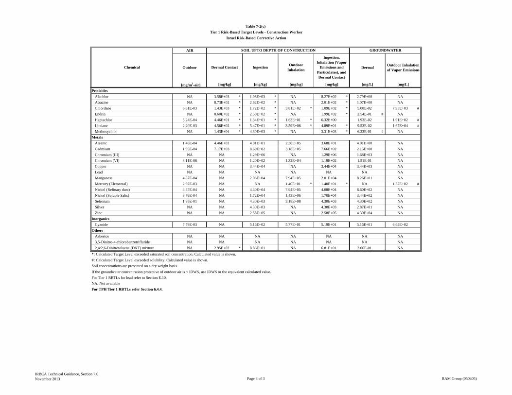
AIR
Outdoor DermalOutdoor Inhalation of Vapor Emissions
[mg/m3-air]
Table 7-2(c)
Tier 1 Risk-Based Target Levels - Construction Worker
Israel Risk-Based Corrective Action
Chemical
SOIL UPTO DEPTH OF CONSTRUCTION GROUNDWATER
Dermal Contact IngestionOutdoor
Inhalation
Ingestion, Inhalation (Vapor
Emissions and Particulates), and Dermal Contact
[mg/L] [mg/L][mg/kg] [mg/kg] [mg/kg] [mg/kg]
Pesticides
Alachlor NA 3.58E+03 * 1.08E+03 * NA 8.27E+02 * 2.79E+00 NA
Atrazine NA 8.73E+02 * 2.62E+02 * NA 2.01E+02 * 1.07E+00 NA
Chlordane 6.81E-03 1.43E+03 * 1.72E+02 * 3.81E+02 * 1.09E+02 * 5.08E-02 7.93E+03 #
Endrin NA 8.60E+02 * 2.58E+02 * NA 1.99E+02 * 2.54E-01 # NA
Heptachlor 5.24E-04 4.46E+01 * 1.34E+01 * 1.63E+01 * 6.32E+00 1.93E-02 1.91E+02 #
Lindane 2.20E-03 4.56E+02 * 5.47E+01 * 3.59E+06 * 4.89E+01 * 9.53E-02 1.67E+04 #
Methoxychlor NA 1.43E+04 * 4.30E+03 * NA 3.31E+03 * 6.23E-01 # NA
Metals
Arsenic 1.46E-04 4.46E+02 4.01E+01 2.38E+05 3.68E+01 4.01E+00 NA
Cadmium 1.95E-04 7.17E+03 8.60E+02 3.18E+05 7.66E+02 2.15E+00 NA
Chromium (III) NA NA 1.29E+06 NA 1.29E+06 1.68E+03 NA
Chromium (VI) 8.11E-06 NA 1.20E+02 1.32E+04 1.19E+02 1.51E-01 NA
Copper NA NA 3.44E+04 NA 3.44E+04 3.44E+03 NA
Lead NA NA NA NA NA NA NA
Manganese 4.87E-04 NA 2.06E+04 7.94E+05 2.01E+04 8.26E+01 NA
Mercury (Elemental) 2.92E-03 NA NA 1.40E+01 * 1.40E+01 * NA 1.32E+02 #
Nickel (Refinary dust) 4.87E-04 NA 4.30E+04 7.94E+05 4.08E+04 8.60E+02 NA
Nickel (Soluble Salts) 8.76E-04 NA 1.72E+04 1.43E+06 1.70E+04 3.44E+02 NA
Selenium 1.95E-01 NA 4.30E+03 3.18E+08 4.30E+03 4.30E+02 NA
Silver NA NA 4.30E+03 NA 4.30E+03 2.87E+01 NA
Zinc NA NA 2.58E+05 NA 2.58E+05 4.30E+04 NA
Inorganics
Cyanide 7.79E-03 NA 5.16E+02 5.77E+01 5.19E+01 5.16E+01 6.64E+02
Others
Asbestos NA NA NA NA NA NA NA
3,5-Dinitro-4-chlorobenzotrifluride NA NA NA NA NA NA NA
2,4/2,6-Dinitrotoluene (DNT) mixture NA 2.95E+02 * 8.86E+01 NA 6.81E+01 3.06E-01 NA
*: Calculated Target Level exceeded saturated soil concentration. Calculated value is shown.
#: Calculated Target Level exceeded solubility. Calculated value is shown.
Soil concentrations are presented on a dry weight basis.
If the groundwater concentration protective of outdoor air is < IDWS, use IDWS or the equivalent calculated value.
For Tier 1 RBTLs for lead refer to Section E.10.
NA: Not available
For TPH Tier 1 RBTLs refer Section 6.4.4.
IRBCA Technical Guidance, Section 7.0November 2013 Page 3 of 3 RAM Group (050405)
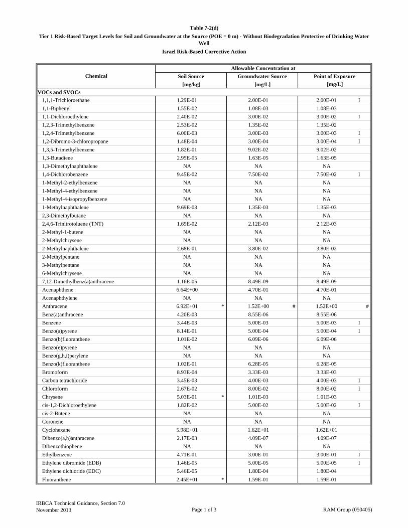
[mg/kg] [mg/L]
VOCs and SVOCs
1,1,1-Trichloroethane 1.29E-01 2.00E-01 2.00E-01 I
1,1-Biphenyl 1.55E-02 1.08E-03 1.08E-03
1,1-Dichloroethylene 2.40E-02 3.00E-02 3.00E-02 I
1,2,3-Trimethylbenzene 2.53E-02 1.35E-02 1.35E-02
1,2,4-Trimethylbenzene 6.00E-03 3.00E-03 3.00E-03 I
1,2-Dibromo-3-chloropropane 1.48E-04 3.00E-04 3.00E-04 I
1,3,5-Trimethylbenzene 1.82E-01 9.02E-02 9.02E-02
1,3-Butadiene 2.95E-05 1.63E-05 1.63E-05
1,3-Dimethylnaphthalene NA NA NA
1,4-Dichlorobenzene 9.45E-02 7.50E-02 7.50E-02 I
1-Methyl-2-ethylbenzene NA NA NA
1-Methyl-4-ethylbenzene NA NA NA
1-Methyl-4-isopropylbenzene NA NA NA
1-Methylnaphthalene 9.69E-03 1.35E-03 1.35E-03
2,3-Dimethylbutane NA NA NA
2,4,6-Trinitrotoluene (TNT) 1.69E-02 2.12E-03 2.12E-03
2-Methyl-1-butene NA NA NA
2-Methylchrysene NA NA NA
2-Methylnaphthalene 2.68E-01 3.80E-02 3.80E-02
2-Methylpentane NA NA NA
3-Methylpentane NA NA NA
6-Methylchrysene NA NA NA
7,12-Dimethylbenz(a)anthracene 1.16E-05 8.49E-09 8.49E-09
Acenaphthene 6.64E+00 4.70E-01 4.70E-01
Acenaphthylene NA NA NA
Anthracene 6.92E+01 * 1.52E+00 # 1.52E+00 #
Benz(a)anthracene 4.20E-03 8.55E-06 8.55E-06
Benzene 3.44E-03 5.00E-03 5.00E-03 I
Benzo(a)pyrene 8.14E-01 5.00E-04 5.00E-04 I
Benzo(b)fluoranthene 1.01E-02 6.09E-06 6.09E-06
Benzo(e)pyrene NA NA NA
Benzo(g,h,i)perylene NA NA NA
Benzo(k)fluoranthene 1.02E-01 6.28E-05 6.28E-05
Bromoform 8.93E-04 3.33E-03 3.33E-03
Carbon tetrachloride 3.45E-03 4.00E-03 4.00E-03 I
Chloroform 2.67E-02 8.00E-02 8.00E-02 I
Chrysene 5.03E-01 * 1.01E-03 1.01E-03
cis-1,2-Dichloroethylene 1.82E-02 5.00E-02 5.00E-02 I
cis-2-Butene NA NA NA
Coronene NA NA NA
Cyclohexane 5.98E+01 1.62E+01 1.62E+01
Dibenzo(a,h)anthracene 2.17E-03 4.09E-07 4.09E-07
Dibenzothiophene NA NA NA
Ethylbenzene 4.71E-01 3.00E-01 3.00E-01 I
Ethylene dibromide (EDB) 1.46E-05 5.00E-05 5.00E-05 I
Ethylene dichloride (EDC) 5.46E-05 1.80E-04 1.80E-04
Fluoranthene 2.45E+01 * 1.59E-01 1.59E-01
Allowable Concentration at
[mg/L]
Table 7-2(d)
Tier 1 Risk-Based Target Levels for Soil and Groundwater at the Source (POE = 0 m) - Without Biodegradation Protective of Drinking Water Well
Chemical Soil Source Groundwater Source Point of Exposure
Israel Risk-Based Corrective Action
IRBCA Technical Guidance, Section 7.0November 2013 Page 1 of 3 RAM Group (050405)

[mg/kg] [mg/L]
Allowable Concentration at
[mg/L]
Table 7-2(d)
Tier 1 Risk-Based Target Levels for Soil and Groundwater at the Source (POE = 0 m) - Without Biodegradation Protective of Drinking Water Well
Chemical Soil Source Groundwater Source Point of Exposure
Israel Risk-Based Corrective Action
Fluorene 6.62E+00 2.59E-01 2.59E-01
HMX (1,3,5,7-tetranitro-1,3,5,7- tetrazocane) 1.25E+00 7.60E-01 7.60E-01
Indene NA NA NA
Indeno(1,2,3-cd)pyrene 3.30E-02 6.11E-06 6.11E-06
Isopropylbenzene 1.24E+00 5.29E-01 5.29E-01
Methyl teriary butyl ether (MTBE) 8.53E-03 4.00E-02 4.00E-02 I
Methylcyclohexane NA NA NA
Methylcyclopentane NA NA NA
Naphthalene 8.27E-04 1.86E-04 1.86E-04
n-Butylbenzene 1.36E+00 2.95E-01 2.95E-01
n-Heptane NA NA NA
n-Hexane 1.78E+01 4.70E-01 4.70E-01
n-Pentane 7.11E+01 2.70E+00 2.70E+00
n-Propylbenzene 1.76E+00 6.67E-01 6.67E-01
Perylene NA NA NA
Phenanthrene NA NA NA
Pyrene 1.41E+01 * 9.35E-02 9.35E-02
RDX 2.45E-04 5.90E-04 5.90E-04
sec-Butylbenzene NA NA NA
Styrene 7.32E-02 5.00E-02 5.00E-02 I
tert-Butylbenzene NA NA NA
Tetrachloroethylene 7.99E-03 1.00E-02 1.00E-02 I
Toluene 6.69E-01 7.00E-01 7.00E-01 I
trans-1,2-Dichloroethylene 1.82E-02 5.00E-02 5.00E-02 I
trans-2-Butene NA NA NA
Trichloroethylene 1.62E-02 3.00E-02 3.00E-02 I
Vinyl chloride 4.03E-04 5.00E-04 5.00E-04 I
Xylene (m) 1.36E+00 1.00E+00 1.00E+00 I
Xylene (o) 1.34E+00 1.00E+00 1.00E+00 I
Xylene (p) 3.27E-01 2.42E-01 2.42E-01
Xylenes (total) 6.69E-01 5.00E-01 5.00E-01 I
Pesticides
Alachlor 4.14E-03 4.00E-03 4.00E-03 I
Atrazine 1.58E-03 2.00E-03 2.00E-03 I
Chlordane 9.38E-01 1.00E-02 1.00E-02 I
Endrin 1.12E-01 2.00E-03 2.00E-03 I
Heptachlor 4.58E-02 4.00E-04 4.00E-04 I
Lindane 7.95E-03 1.00E-03 1.00E-03 I
Methoxychlor 1.57E+00 2.10E-02 2.10E-02
Metals
Arsenic 8.06E-01 1.00E-02 1.00E-02 I
Cadmium 1.04E+00 5.00E-03 5.00E-03 I
Chromium (III) 2.50E+05 5.00E-02 5.00E-02 I
Chromium (VI) 2.64E+00 5.00E-02 5.00E-02 I
Copper 1.55E+02 1.40E+00 1.40E+00 I
Lead 2.79E-01 1.00E-02 1.00E-02 I
Manganese 2.78E+01 2.00E-01 2.00E-01 I
Mercury (Elemental) 1.45E-01 1.00E-03 1.00E-03 I
Nickel (Refinary dust) 3.61E+00 2.00E-02 2.00E-02 I
IRBCA Technical Guidance, Section 7.0November 2013 Page 2 of 3 RAM Group (050405)
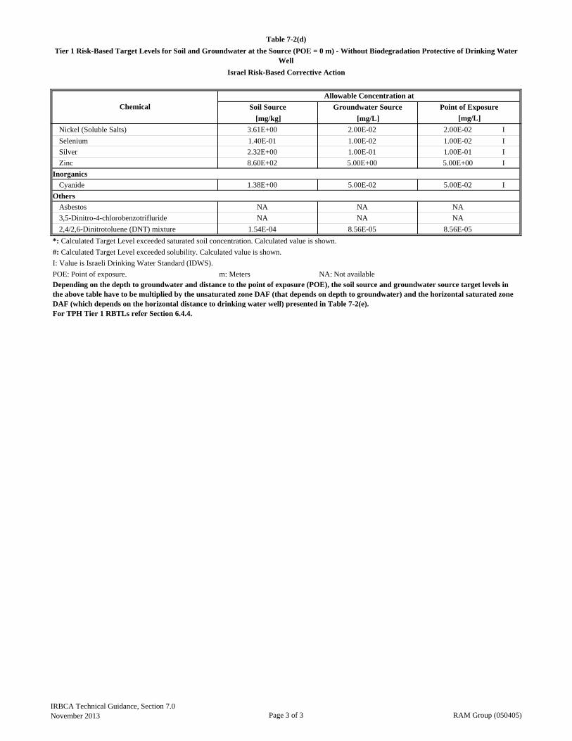
[mg/kg] [mg/L]
Allowable Concentration at
[mg/L]
Table 7-2(d)
Tier 1 Risk-Based Target Levels for Soil and Groundwater at the Source (POE = 0 m) - Without Biodegradation Protective of Drinking Water Well
Chemical Soil Source Groundwater Source Point of Exposure
Israel Risk-Based Corrective Action
Nickel (Soluble Salts) 3.61E+00 2.00E-02 2.00E-02 I
Selenium 1.40E-01 1.00E-02 1.00E-02 I
Silver 2.32E+00 1.00E-01 1.00E-01 I
Zinc 8.60E+02 5.00E+00 5.00E+00 I
Inorganics
Cyanide 1.38E+00 5.00E-02 5.00E-02 I
Others
Asbestos NA NA NA
3,5-Dinitro-4-chlorobenzotrifluride NA NA NA
2,4/2,6-Dinitrotoluene (DNT) mixture 1.54E-04 8.56E-05 8.56E-05
*: Calculated Target Level exceeded saturated soil concentration. Calculated value is shown.
#: Calculated Target Level exceeded solubility. Calculated value is shown.
I: Value is Israeli Drinking Water Standard (IDWS).
POE: Point of exposure. m: Meters NA: Not available
For TPH Tier 1 RBTLs refer Section 6.4.4.
Depending on the depth to groundwater and distance to the point of exposure (POE), the soil source and groundwater source target levels in the above table have to be multiplied by the unsaturated zone DAF (that depends on depth to groundwater) and the horizontal saturated zone DAF (which depends on the horizontal distance to drinking water well) presented in Table 7-2(e).
IRBCA Technical Guidance, Section 7.0November 2013 Page 3 of 3 RAM Group (050405)
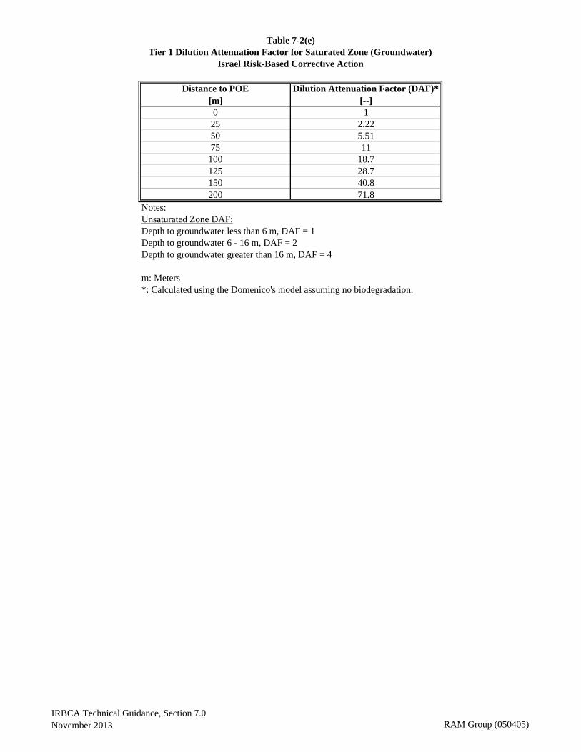
Distance to POE Dilution Attenuation Factor (DAF)*[m] [--]0 1
25 2.2250 5.5175 11
100 18.7125 28.7150 40.8200 71.8
Notes:Unsaturated Zone DAF:Depth to groundwater less than 6 m, DAF = 1Depth to groundwater 6 - 16 m, DAF = 2Depth to groundwater greater than 16 m, DAF = 4
m: Meters*: Calculated using the Domenico's model assuming no biodegradation.
Table 7-2(e)Tier 1 Dilution Attenuation Factor for Saturated Zone (Groundwater)
Israel Risk-Based Corrective Action
IRBCA Technical Guidance, Section 7.0November 2013 RAM Group (050405)
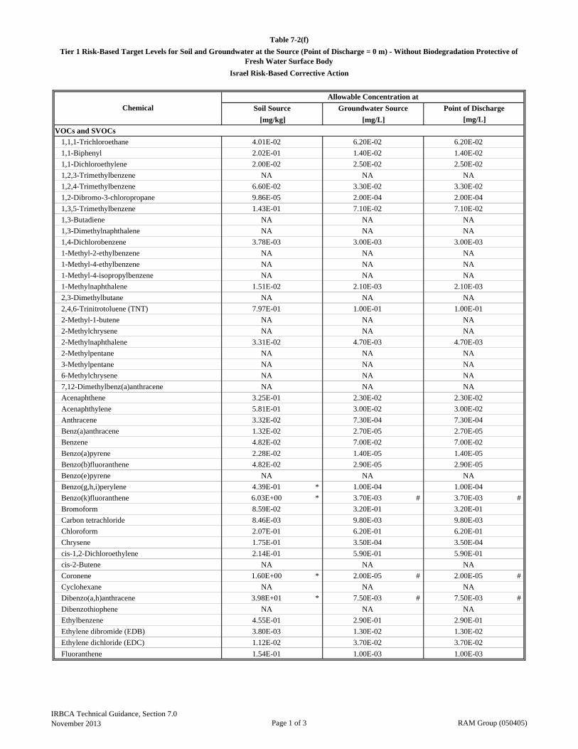
[mg/kg] [mg/L]
VOCs and SVOCs
1,1,1-Trichloroethane 4.01E-02 6.20E-02 6.20E-02
1,1-Biphenyl 2.02E-01 1.40E-02 1.40E-02
1,1-Dichloroethylene 2.00E-02 2.50E-02 2.50E-02
1,2,3-Trimethylbenzene NA NA NA
1,2,4-Trimethylbenzene 6.60E-02 3.30E-02 3.30E-02
1,2-Dibromo-3-chloropropane 9.86E-05 2.00E-04 2.00E-04
1,3,5-Trimethylbenzene 1.43E-01 7.10E-02 7.10E-02
1,3-Butadiene NA NA NA
1,3-Dimethylnaphthalene NA NA NA
1,4-Dichlorobenzene 3.78E-03 3.00E-03 3.00E-03
1-Methyl-2-ethylbenzene NA NA NA
1-Methyl-4-ethylbenzene NA NA NA
1-Methyl-4-isopropylbenzene NA NA NA
1-Methylnaphthalene 1.51E-02 2.10E-03 2.10E-03
2,3-Dimethylbutane NA NA NA
2,4,6-Trinitrotoluene (TNT) 7.97E-01 1.00E-01 1.00E-01
2-Methyl-1-butene NA NA NA
2-Methylchrysene NA NA NA
2-Methylnaphthalene 3.31E-02 4.70E-03 4.70E-03
2-Methylpentane NA NA NA
3-Methylpentane NA NA NA
6-Methylchrysene NA NA NA
7,12-Dimethylbenz(a)anthracene NA NA NA
Acenaphthene 3.25E-01 2.30E-02 2.30E-02
Acenaphthylene 5.81E-01 3.00E-02 3.00E-02
Anthracene 3.32E-02 7.30E-04 7.30E-04
Benz(a)anthracene 1.32E-02 2.70E-05 2.70E-05
Benzene 4.82E-02 7.00E-02 7.00E-02
Benzo(a)pyrene 2.28E-02 1.40E-05 1.40E-05
Benzo(b)fluoranthene 4.82E-02 2.90E-05 2.90E-05
Benzo(e)pyrene NA NA NA
Benzo(g,h,i)perylene 4.39E-01 * 1.00E-04 1.00E-04
Benzo(k)fluoranthene 6.03E+00 * 3.70E-03 # 3.70E-03 #
Bromoform 8.59E-02 3.20E-01 3.20E-01
Carbon tetrachloride 8.46E-03 9.80E-03 9.80E-03
Chloroform 2.07E-01 6.20E-01 6.20E-01
Chrysene 1.75E-01 3.50E-04 3.50E-04
cis-1,2-Dichloroethylene 2.14E-01 5.90E-01 5.90E-01
cis-2-Butene NA NA NA
Coronene 1.60E+00 * 2.00E-05 # 2.00E-05 #
Cyclohexane NA NA NA
Dibenzo(a,h)anthracene 3.98E+01 * 7.50E-03 # 7.50E-03 #
Dibenzothiophene NA NA NA
Ethylbenzene 4.55E-01 2.90E-01 2.90E-01
Ethylene dibromide (EDB) 3.80E-03 1.30E-02 1.30E-02
Ethylene dichloride (EDC) 1.12E-02 3.70E-02 3.70E-02
Fluoranthene 1.54E-01 1.00E-03 1.00E-03
Table 7-2(f)
Tier 1 Risk-Based Target Levels for Soil and Groundwater at the Source (Point of Discharge = 0 m) - Without Biodegradation Protective of Fresh Water Surface Body
Israel Risk-Based Corrective Action
Chemical
Allowable Concentration at
Soil Source Groundwater Source Point of Discharge
[mg/L]
IRBCA Technical Guidance, Section 7.0November 2013 Page 1 of 3 RAM Group (050405)

[mg/kg] [mg/L]
Table 7-2(f)
Tier 1 Risk-Based Target Levels for Soil and Groundwater at the Source (Point of Discharge = 0 m) - Without Biodegradation Protective of Fresh Water Surface Body
Israel Risk-Based Corrective Action
Chemical
Allowable Concentration at
Soil Source Groundwater Source Point of Discharge
[mg/L]
Fluorene 9.97E-02 3.90E-03 3.90E-03
HMX (1,3,5,7-tetranitro-1,3,5,7- tetrazocane) 2.46E-01 1.50E-01 1.50E-01
Indene NA NA NA
Indeno(1,2,3-cd)pyrene 2.60E-01 4.80E-05 4.80E-05
Isopropylbenzene 6.09E-03 2.60E-03 2.60E-03
Methyl teriary butyl ether (MTBE) 2.36E+00 1.11E+01 1.11E+01
Methylcyclohexane NA NA NA
Methylcyclopentane NA NA NA
Naphthalene 4.91E-03 1.10E-03 1.10E-03
n-Butylbenzene NA NA NA
n-Heptane NA NA NA
n-Hexane 2.20E-02 5.80E-04 5.80E-04
n-Pentane NA NA NA
n-Propylbenzene 3.38E-01 1.28E-01 1.28E-01
Perylene 2.16E-01 2.00E-05 2.00E-05
Phenanthrene 1.57E-02 4.00E-04 4.00E-04
Pyrene 3.02E-01 2.00E-03 2.00E-03
RDX 7.49E-02 1.80E-01 1.80E-01
sec-Butylbenzene NA NA NA
Styrene 1.46E-01 1.00E-01 1.00E-01
tert-Butylbenzene NA NA NA
Tetrachloroethylene 9.59E-02 1.20E-01 1.20E-01
Toluene 1.24E-01 1.30E-01 1.30E-01
trans-1,2-Dichloroethylene 2.14E-01 5.90E-01 5.90E-01
trans-2-Butene NA NA NA
Trichloroethylene 1.95E-01 3.60E-01 3.60E-01
Vinyl chloride 6.29E-01 7.80E-01 7.80E-01
Xylene (m) 2.45E-03 1.80E-03 1.80E-03
Xylene (o) NA NA NA
Xylene (p) NA NA NA
Xylenes (total) 1.34E-01 1.00E-01 1.00E-01
Pesticides
Alachlor 5.18E-04 5.00E-04 5.00E-04
Atrazine 1.42E-03 1.80E-03 1.80E-03
Chlordane 4.03E-04 4.30E-06 4.30E-06
Endrin 2.01E-03 3.60E-05 3.60E-05
Heptachlor 4.35E-04 3.80E-06 3.80E-06
Lindane 6.36E-04 8.00E-05 8.00E-05
Methoxychlor 1.42E-03 1.90E-05 1.90E-05
Metals
Arsenic 8.06E+00 1.00E-01 1.00E-01
Cadmium 1.04E+00 5.00E-03 5.00E-03
Chromium (III) 2.50E+05 5.00E-02 5.00E-02
Chromium (VI) 5.81E-01 1.10E-02 1.10E-02
Copper 2.21E+00 2.00E-02 2.00E-02
Lead 2.23E-01 8.00E-03 8.00E-03
Manganese NA NA NA
Mercury (Elemental) 7.23E-02 5.00E-04 5.00E-04
Nickel (Refinary dust) 9.02E+00 5.00E-02 5.00E-02
IRBCA Technical Guidance, Section 7.0November 2013 Page 2 of 3 RAM Group (050405)
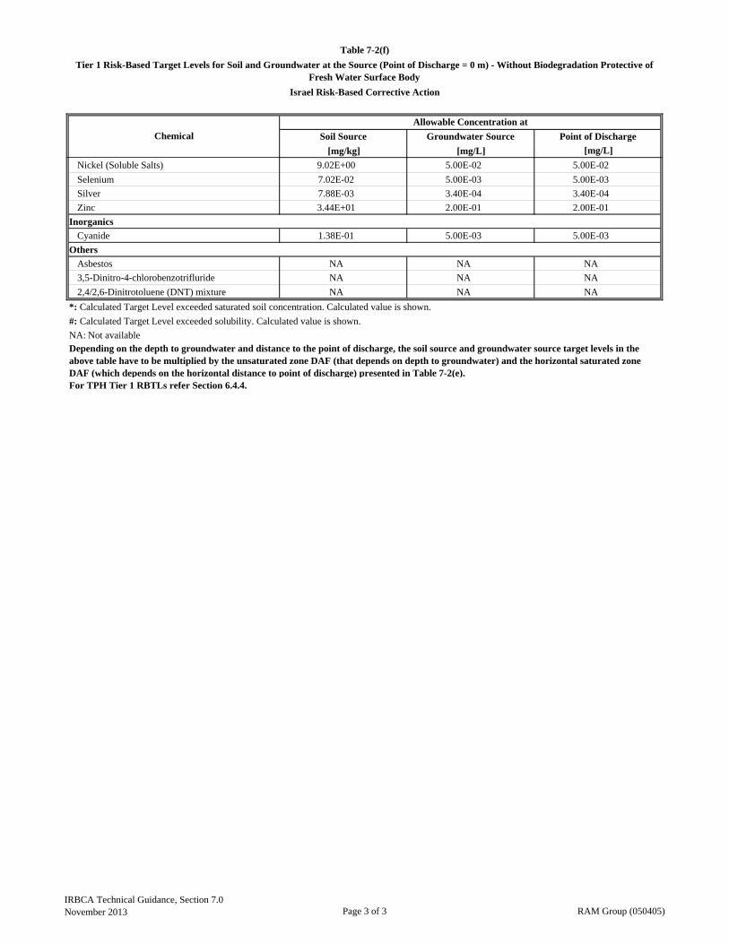
[mg/kg] [mg/L]
Table 7-2(f)
Tier 1 Risk-Based Target Levels for Soil and Groundwater at the Source (Point of Discharge = 0 m) - Without Biodegradation Protective of Fresh Water Surface Body
Israel Risk-Based Corrective Action
Chemical
Allowable Concentration at
Soil Source Groundwater Source Point of Discharge
[mg/L]
Nickel (Soluble Salts) 9.02E+00 5.00E-02 5.00E-02
Selenium 7.02E-02 5.00E-03 5.00E-03
Silver 7.88E-03 3.40E-04 3.40E-04
Zinc 3.44E+01 2.00E-01 2.00E-01
Inorganics
Cyanide 1.38E-01 5.00E-03 5.00E-03
Others
Asbestos NA NA NA
3,5-Dinitro-4-chlorobenzotrifluride NA NA NA
2,4/2,6-Dinitrotoluene (DNT) mixture NA NA NA
*: Calculated Target Level exceeded saturated soil concentration. Calculated value is shown.
#: Calculated Target Level exceeded solubility. Calculated value is shown.
NA: Not available
For TPH Tier 1 RBTLs refer Section 6.4.4.
Depending on the depth to groundwater and distance to the point of discharge, the soil source and groundwater source target levels in the above table have to be multiplied by the unsaturated zone DAF (that depends on depth to groundwater) and the horizontal saturated zone DAF (which depends on the horizontal distance to point of discharge) presented in Table 7-2(e).
IRBCA Technical Guidance, Section 7.0November 2013 Page 3 of 3 RAM Group (050405)

IRBCA Technical Guidance, Figures RAM Group (050405) November 2013
FIGURES
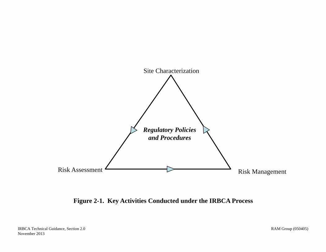
Regulatory Policies and Procedures
Site Characterization
Risk Assessment Risk Management
Figure 2-1. Key Activities Conducted under the IRBCA Process
IRBCA Technical Guidance, Section 2.0November 2013
RAM Group (050405)
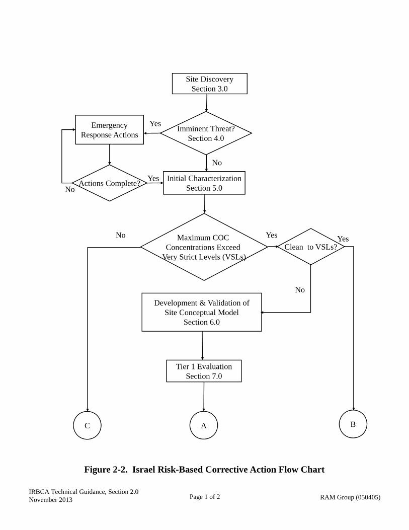
Development & Validation ofSite Conceptual Model
Section 6.0
Site DiscoverySection 3.0
Emergency Response Actions
Tier 1 EvaluationSection 7.0
No
Imminent Threat?Section 4.0
Initial CharacterizationSection 5.0
Actions Complete?
A
No
YesNo
Yes
Yes
Clean to VSLs?
No
Yes
B
Figure 2-2. Israel Risk-Based Corrective Action Flow Chart
C
IRBCA Technical Guidance, Section 2.0November 2013 Page 1 of 2 RAM Group (050405)
Maximum COC Concentrations Exceed
Very Strict Levels (VSLs)
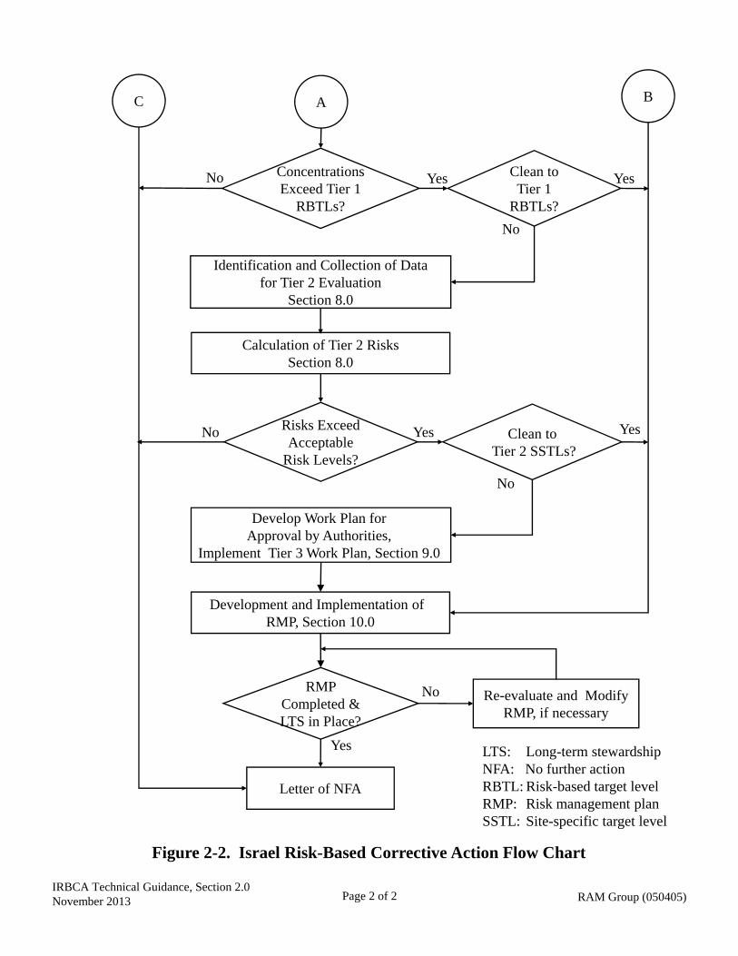
Figure 2-2. Israel Risk-Based Corrective Action Flow Chart
RMP Completed & LTS in Place?
Letter of NFA
Yes
No
ConcentrationsExceed Tier 1
RBTLs?
Identification and Collection of Data for Tier 2 Evaluation
Section 8.0
Calculation of Tier 2 RisksSection 8.0
Risks Exceed Acceptable
Risk Levels?
Re-evaluate and Modify RMP, if necessary
No
No Yes Clean toTier 1
RBTLs?
No
Yes
A B
Yes Clean toTier 2 SSTLs?
No
Yes
Development and Implementation of RMP, Section 10.0
Develop Work Plan for Approval by Authorities,
Implement Tier 3 Work Plan, Section 9.0
LTS: Long-term stewardshipNFA: No further actionRBTL: Risk-based target levelRMP: Risk management planSSTL: Site-specific target level
C
Page 2 of 2 RAM Group (050405)IRBCA Technical Guidance, Section 2.0November 2013
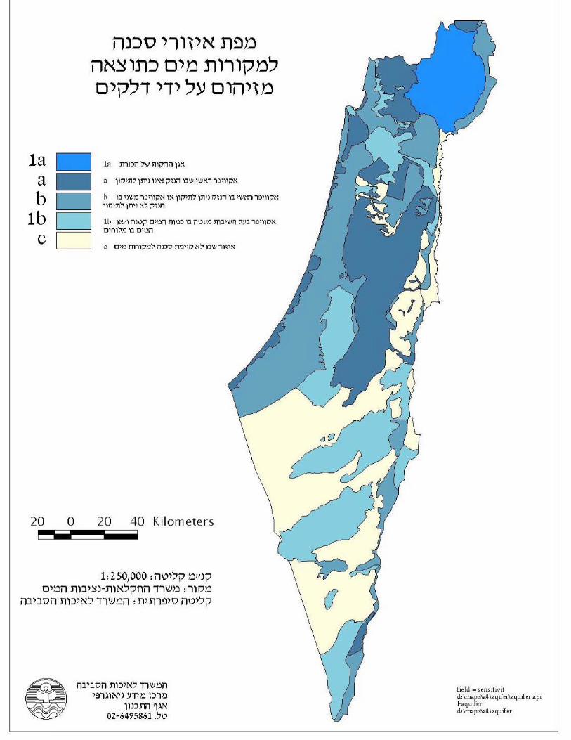
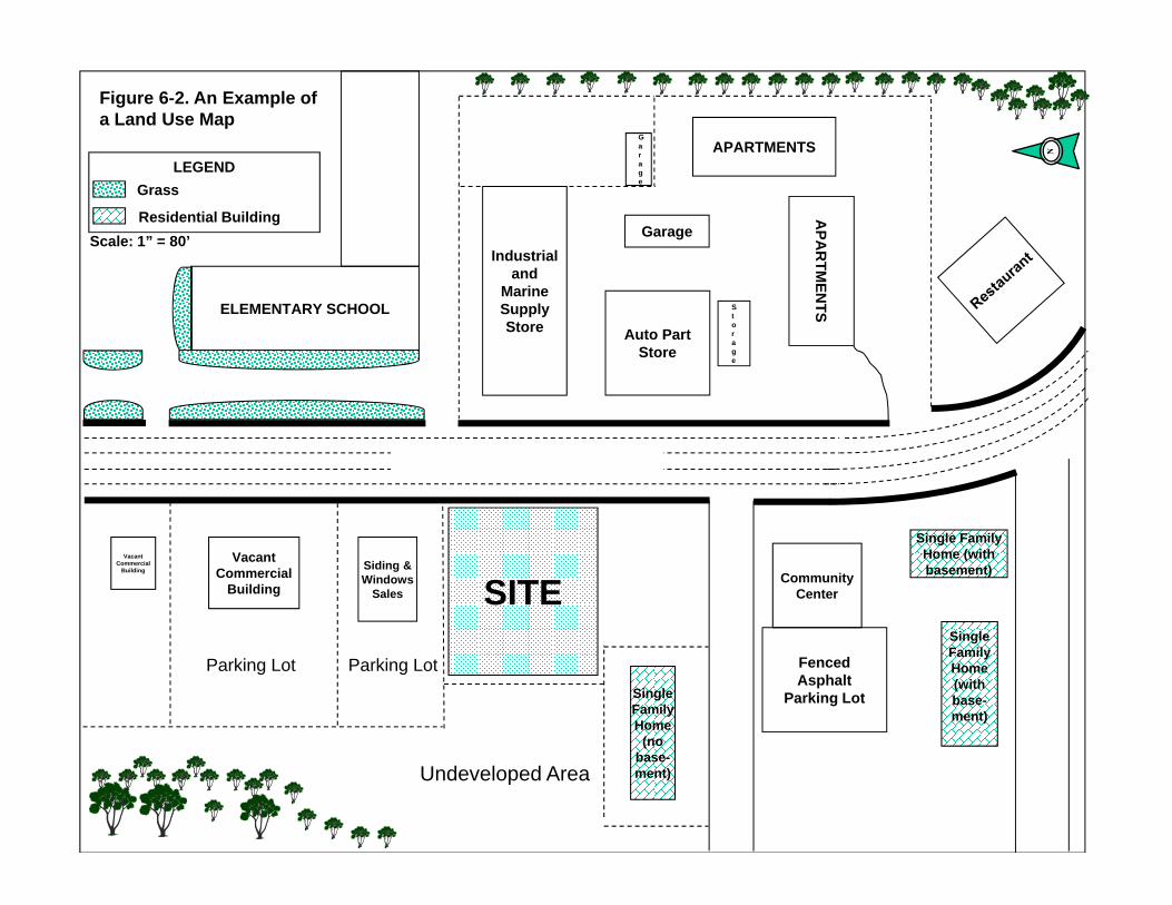
LEGEND
SITEVacant
Commercial Building
Vacant Commercial
Building
Siding & Windows
Sales
Fenced Asphalt
Parking Lot
Community Center
Single Family Home
(no base-ment)
Single Family Home (with basement)
Single Family Home (with base-ment)
ELEMENTARY SCHOOL
Industrial and
Marine Supply Store Auto Part
Store
Garage
Garage
AP
AR
TM
EN
TS
APARTMENTS
Storage
Figure 6-2. An Example of a Land Use Map
Grass
Residential Building
Scale: 1” = 80’
Parking Lot Parking Lot
Undeveloped Area

IRBCA Technical Guidance, Figures RAM Group (050405) November 2013
APPENDICES
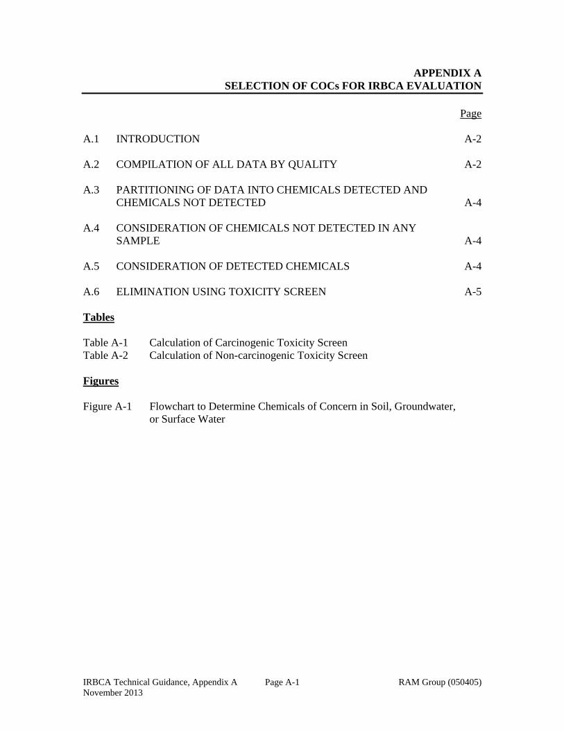
IRBCA Technical Guidance, Appendix A RAM Group (050405) November 2013
Page A-1
APPENDIX A SELECTION OF COCs FOR IRBCA EVALUATION
Page A.1 INTRODUCTION A-2 A.2 COMPILATION OF ALL DATA BY QUALITY A-2 A.3 PARTITIONING OF DATA INTO CHEMICALS DETECTED AND
CHEMICALS NOT DETECTED A-4 A.4 CONSIDERATION OF CHEMICALS NOT DETECTED IN ANY SAMPLE A-4 A.5 CONSIDERATION OF DETECTED CHEMICALS A-4 A.6 ELIMINATION USING TOXICITY SCREEN A-5 Tables Table A-1 Calculation of Carcinogenic Toxicity Screen Table A-2 Calculation of Non-carcinogenic Toxicity Screen Figures Figure A-1 Flowchart to Determine Chemicals of Concern in Soil, Groundwater,
or Surface Water
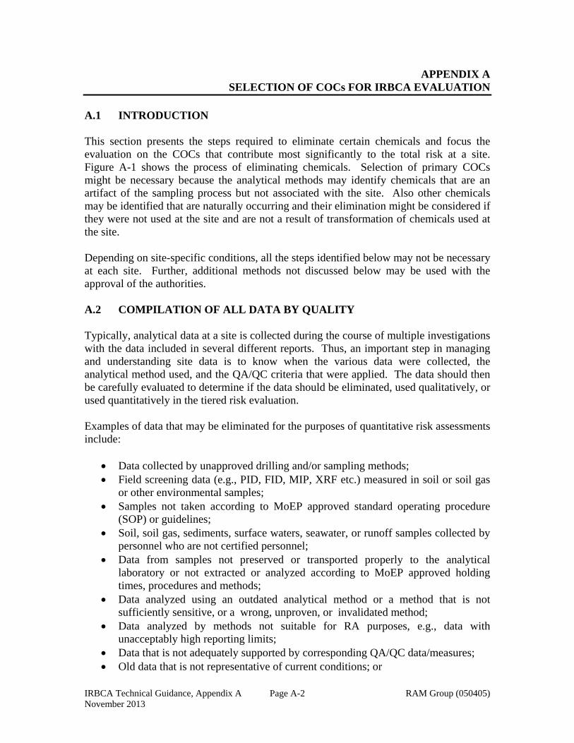
IRBCA Technical Guidance, Appendix A RAM Group (050405) November 2013
Page A-2
APPENDIX A SELECTION OF COCs FOR IRBCA EVALUATION
A.1 INTRODUCTION This section presents the steps required to eliminate certain chemicals and focus the evaluation on the COCs that contribute most significantly to the total risk at a site. Figure A-1 shows the process of eliminating chemicals. Selection of primary COCs might be necessary because the analytical methods may identify chemicals that are an artifact of the sampling process but not associated with the site. Also other chemicals may be identified that are naturally occurring and their elimination might be considered if they were not used at the site and are not a result of transformation of chemicals used at the site. Depending on site-specific conditions, all the steps identified below may not be necessary at each site. Further, additional methods not discussed below may be used with the approval of the authorities. A.2 COMPILATION OF ALL DATA BY QUALITY Typically, analytical data at a site is collected during the course of multiple investigations with the data included in several different reports. Thus, an important step in managing and understanding site data is to know when the various data were collected, the analytical method used, and the QA/QC criteria that were applied. The data should then be carefully evaluated to determine if the data should be eliminated, used qualitatively, or used quantitatively in the tiered risk evaluation. Examples of data that may be eliminated for the purposes of quantitative risk assessments include:
Data collected by unapproved drilling and/or sampling methods; Field screening data (e.g., PID, FID, MIP, XRF etc.) measured in soil or soil gas
or other environmental samples; Samples not taken according to MoEP approved standard operating procedure
(SOP) or guidelines; Soil, soil gas, sediments, surface waters, seawater, or runoff samples collected by
personnel who are not certified personnel; Data from samples not preserved or transported properly to the analytical
laboratory or not extracted or analyzed according to MoEP approved holding times, procedures and methods;
Data analyzed using an outdated analytical method or a method that is not sufficiently sensitive, or a wrong, unproven, or invalidated method;
Data analyzed by methods not suitable for RA purposes, e.g., data with unacceptably high reporting limits;
Data that is not adequately supported by corresponding QA/QC data/measures; Old data that is not representative of current conditions; or
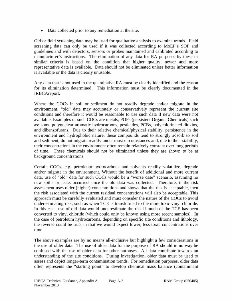
IRBCA Technical Guidance, Appendix A RAM Group (050405) November 2013
Page A-3
Data collected prior to any remediation at the site. Old or field screening data may be used for qualitative analysis to examine trends. Field screening data can only be used if it was collected according to MoEP’s SOP and guidelines and with detectors, sensors or probes maintained and calibrated according to manufacturer’s instructions. The elimination of any data for RA purposes by these or similar criteria is based on the condition that higher quality, newer and more representative data is available. Data should not be eliminated unless better information is available or the data is clearly unusable. Any data that is not used in the quantitative RA must be clearly identified and the reason for its elimination determined. This information must be clearly documented in the IRBCAreport. Where the COCs in soil or sediment do not readily degrade and/or migrate in the environment, “old” data may accurately or conservatively represent the current site conditions and therefore it would be reasonable to use such data if new data were not available. Examples of such COCs are metals, POPs (persistent Organic Chemicals) such as: some polynuclear aromatic hydrocarbons, pesticides, PCBs, polychlorinated dioxins, and dibenzofurans. Due to their relative chemical/physical stability, persistence in the environment and hydrophobic nature, these compounds tend to strongly adsorb to soil and sediment, do not migrate readily under most circumstances and, due to their stability, their concentrations in the environment often remain relatively constant over long periods of time. These chemicals should not be eliminated unless they are shown to be at background concentrations.
Certain COCs, e.g. petroleum hydrocarbons and solvents readily volatilize, degrade and/or migrate in the environment. Without the benefit of additional and more current data, use of “old” data for such COCs would be a “worse case” scenario, assuming no new spills or leaks occurred since the old data was collected. Therefore, if the risk assessment uses older (higher) concentrations and shows that the risk is acceptable, then the risk associated with the current residual concentrations will also be acceptable. This approach must be carefully evaluated and must consider the nature of the COCs to avoid underestimating risk, such as when TCE is transformed to the more toxic vinyl chloride. In this case, use of old data would underestimate the risk if much of the TCE has been converted to vinyl chloride (which could only be known using more recent samples). In the case of petroleum hydrocarbons, depending on specific site conditions and lithology, the reverse could be true, in that we would expect lower, less toxic concentrations over time. The above examples are by no means all-inclusive but highlight a few considerations in the use of older data. The use of older data for the purpose of RA should in no way be confused with the use of older data for other purposes. All data contribute towards an understanding of the site conditions. During investigation, older data must be used to assess and depict longer-term contamination trends. For remediation purposes, older data often represents the “starting point” to develop chemical mass balance (contaminant
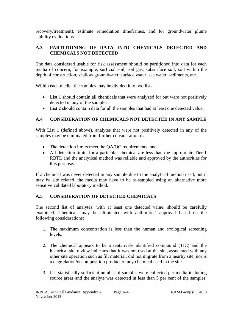
IRBCA Technical Guidance, Appendix A RAM Group (050405) November 2013
Page A-4
recovery/treatment), estimate remediation timeframes, and for groundwater plume stability evaluations. A.3 PARTITIONING OF DATA INTO CHEMICALS DETECTED AND
CHEMICALS NOT DETECTED The data considered usable for risk assessment should be partitioned into data for each media of concern, for example, surficial soil, soil gas, subsurface soil, soil within the depth of construction, shallow groundwater, surface water, sea water, sediments, etc. Within each media, the samples may be divided into two lists.
List 1 should contain all chemicals that were analyzed for but were not positively detected in any of the samples.
List 2 should contain data for all the samples that had at least one detected value. A.4 CONSIDERATION OF CHEMICALS NOT DETECTED IN ANY SAMPLE With List 1 (defined above), analytes that were not positively detected in any of the samples may be eliminated from further consideration if:
The detection limits meet the QA/QC requirements; and All detection limits for a particular chemical are less than the appropriate Tier 1
RBTL and the analytical method was reliable and approved by the authorities for this purpose.
If a chemical was never detected in any sample due to the analytical method used, but it may be site related, the media may have to be re-sampled using an alternative more sensitive validated laboratory method. A.5 CONSIDERATION OF DETECTED CHEMICALS The second list of analytes, with at least one detected value, should be carefully examined. Chemicals may be eliminated with authorities' approval based on the following considerations:
1. The maximum concentration is less than the human and ecological screening levels.
2. The chemical appears to be a tentatively identified compound (TIC) and the historical site review indicates that it was not used at the site, associated with any other site operation such as fill material, did not migrate from a nearby site, nor is a degradation/decomposition product of any chemical used in the site.
3. If a statistically sufficient number of samples were collected per media including source areas and the analyte was detected in less than 5 per cent of the samples.
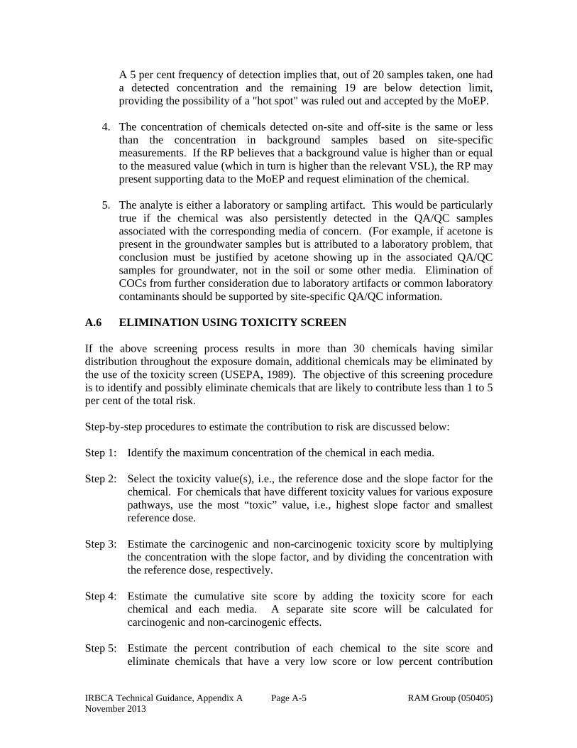
IRBCA Technical Guidance, Appendix A RAM Group (050405) November 2013
Page A-5
A 5 per cent frequency of detection implies that, out of 20 samples taken, one had a detected concentration and the remaining 19 are below detection limit, providing the possibility of a "hot spot" was ruled out and accepted by the MoEP.
4. The concentration of chemicals detected on-site and off-site is the same or less than the concentration in background samples based on site-specific measurements. If the RP believes that a background value is higher than or equal to the measured value (which in turn is higher than the relevant VSL), the RP may present supporting data to the MoEP and request elimination of the chemical.
5. The analyte is either a laboratory or sampling artifact. This would be particularly true if the chemical was also persistently detected in the QA/QC samples associated with the corresponding media of concern. (For example, if acetone is present in the groundwater samples but is attributed to a laboratory problem, that conclusion must be justified by acetone showing up in the associated QA/QC samples for groundwater, not in the soil or some other media. Elimination of COCs from further consideration due to laboratory artifacts or common laboratory contaminants should be supported by site-specific QA/QC information.
A.6 ELIMINATION USING TOXICITY SCREEN If the above screening process results in more than 30 chemicals having similar distribution throughout the exposure domain, additional chemicals may be eliminated by the use of the toxicity screen (USEPA, 1989). The objective of this screening procedure is to identify and possibly eliminate chemicals that are likely to contribute less than 1 to 5 per cent of the total risk. Step-by-step procedures to estimate the contribution to risk are discussed below: Step 1: Identify the maximum concentration of the chemical in each media. Step 2: Select the toxicity value(s), i.e., the reference dose and the slope factor for the
chemical. For chemicals that have different toxicity values for various exposure pathways, use the most “toxic” value, i.e., highest slope factor and smallest reference dose.
Step 3: Estimate the carcinogenic and non-carcinogenic toxicity score by multiplying
the concentration with the slope factor, and by dividing the concentration with the reference dose, respectively.
Step 4: Estimate the cumulative site score by adding the toxicity score for each
chemical and each media. A separate site score will be calculated for carcinogenic and non-carcinogenic effects.
Step 5: Estimate the percent contribution of each chemical to the site score and
eliminate chemicals that have a very low score or low percent contribution
IRBCA Technical Guidance, Appendix A RAM Group (050405) November 2013
Page A-6
relative to the other chemicals. In general, chemicals with a toxicity score of less than 1 per cent may be readily eliminated. In certain cases, depending on the distribution of the toxicity scores, chemicals with the toxicity score of upto 5 per cent may be eliminated. Tables A-1 and A-2 are sample blank spreadsheets that can be used to implement the procedure.
The elimination of any chemical and the rationale used must be clearly documented. Upon completion of theRA, it may be necessary to re-visit the chemicals that were eliminated, especially when using the toxicity screen, and make a determination whether their inclusion may have resulted in an unacceptable risk.

Cmax*SF % Cmax*SF % Cmax*SF %
C1
C2
C3
C4 - Cx
Total NA NA NA NA NA NA
Notes:
Cmax: Maximum concentration
SF: Slope factor (kg-day/mg)
Site toxicity: Sum of toxicity score for each media. In this example, sum of (Cmax * SF) for surficial soil, subsurface soil, and groundwater.
%: Percentage of total toxicity score
NA: Not applicable
Table A-1
Calculation of Carcinogenic Toxicity Screen
Chemical
Surficial Soil Subsurface Soil Groundwater
Site Toxicity% Risk
Contribution by ChemicalCmax SF
Toxicity ScoreToxicity ScoreCmax SF
Toxicity ScoreCmax SF
IRBCA Technical Guidance, Appendix ANovember 2013 RAM Group (050405)
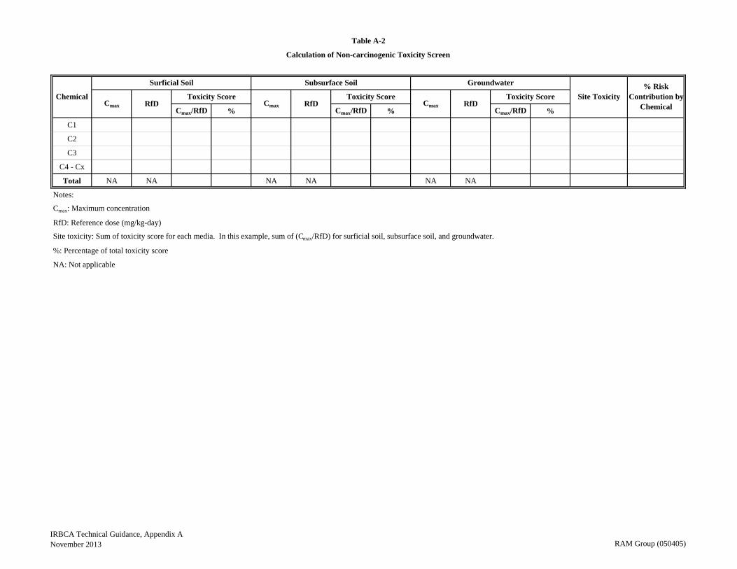
Cmax/RfD % Cmax/RfD % Cmax/RfD %
C1
C2
C3
C4 - Cx
Total NA NA NA NA NA NA
Notes:
Cmax: Maximum concentration
RfD: Reference dose (mg/kg-day)
Site toxicity: Sum of toxicity score for each media. In this example, sum of (Cmax/RfD) for surficial soil, subsurface soil, and groundwater.
%: Percentage of total toxicity score
NA: Not applicable
Table A-2
Calculation of Non-carcinogenic Toxicity Screen
Chemical
Surficial Soil Subsurface Soil Groundwater
Site Toxicity% Risk
Contribution by ChemicalCmax RfD
Toxicity ScoreToxicity ScoreCmax RfD
Toxicity ScoreCmax RfD
IRBCA Technical Guidance, Appendix ANovember 2013 RAM Group (050405)

IRBCA Technical Guidance, Appendix B RAM Group (050405) November 2013
APPENDIX B (Intentionally left blank)

IRBCA Technical Guidance, Appendix C Page C-1 RAM Group (050405) November 2013
APPENDIX C PARAMETERS TO BE CHANGED FOR TIER 2 RISK ASSESSMENTS
Page
C.1 INTRODUCTION C-2 C.2 SOIL PARAMETERS C-2 C.3 BIODECAY RATE C-5 C.4 GROUNDWATER PARAMETERS C-5 C.5 BUILDING PARAMETERS C-8 C.6 SURFACE WATER PARAMETERS FOR SURFACEWATER AND STREAM PROTECTION C-9
IRBCA Technical Guidance, Appendix C Page C-2 RAM Group (050405) November 2013
APPENDIX C PARAMETERS TO BE CHANGED FOR TIER 2 RISK ASSESSMENTS
C.1 INTRODUCTION For a Tier 2 RA, at a minimum site-specific values for the following parameters must be used. C.2 SOIL PARAMETERS Dimension of Surficial Soil Parallel to Wind (Wa) This parameter is used to calculate the risk and target levels for outdoor inhalation of vapors and particulates from surficial zone. It represents the longest dimension of the exposure domain for direct contact with the surficial soil pathway parallel to the wind direction. If wind direction is variable or unknown at the site, the longest dimension of the exposure domain must be used. For example, if the exposure domain is rectangular, the diagonal of the rectangle may be used. If it is circular, use the approximate diameter. Depth to Subsurface Soil Sources (dts) This parameter is used to calculate the risk and target levels for indoor inhalation from subsurface soil. Tier 2 RAs require the use of the actual measured depth of volatile COCs in soil. The most conservative value of this parameter would be the shallowest depth at which the COC is detected or an average of the shallowest depths at which the COC was detected from multiple borings within the exposure unit(s) for this pathway. Either way, the measurements should reflect the distance from the surface to the top of the first zone of impacted soil. Thickness of Capillary Fringe (hc)
This parameter is used to calculate the risk due to indoor inhalation from groundwater. The thickness of the capillary fringe must be representative of the site soils and is primarily dependent on the soil grain size. Typically, the thickness of the capillary fringe is based on literature values because direct measurement is impractical. The sum of the thickness of the capillary fringe and the thickness of the vadose zone should equal the depth to groundwater (i.e., hc + hv = Lgw). Note the groundwater vapor emission model assumes that the capillary fringe is uncontaminated. This may not be an accurate assumption; hence a conservative estimate and a sensitivity analysis for this parameter may be needed. Thickness of Vadose Zone (hv) The thickness of the vadose zone represents the distance from the ground surface to the depth at which the water table is encountered less the thickness of the capillary fringe. The capillary fringe thickness plus the vadose zone thickness equals the depth to
IRBCA Technical Guidance, Appendix C Page C-3 RAM Group (050405) November 2013
groundwater. Soil boring logs may be used to determine the depth to groundwater. This parameter is used to evaluate the indoor inhalation pathway. The thickness of the vadose zone is calculated by subtracting the capillary fringe thickness from the depth to groundwater (Lgw – hc = hv). Vadose Zone Dry Soil Bulk Density (s)
This parameter is used for the calculation of risk or target levels from all indirect exposure pathways that involve equilibrium calculations between various phases. Examples include leaching to groundwater and indoor and outdoor inhalation from soil and groundwater. If multiple measurements from the vadose zone are available or when multiple values are necessary to represent different soil types, the average value may be used. Also see Section 6.7.1 for a discussion related to the determination of dry soil bulk density. Fractional Organic Carbon Content in Vadose Zone (focv)
This parameter is used for the calculation of risk or target levels from all indirect exposure pathways that involve equilibrium calculations between various phases. If measurements of fractional organic matter (not the same as fractional organic carbon) are available, the value must be converted to fractional organic carbon as discussed in Section 6.7.4. Where soil lithology is significantly heterogeneous, samples should be collected at each change in lithology and may be composited into one sample for fractional organic carbon content analysis. If multiple values are available (as is recommended), and if technically appropriate, the average value should be used. For example, assume that soil is impacted between 3 to 5 m below ground surface (bgs) and the water table is at 15 m bgs. If three soil samples at 1.5, 4, and 7 m bgs have been collected for geotechnical parameters, it would not be appropriate to average the values. For the evaluation of indoor inhalation from soil, the sample collected at 7 m bgs is irrelevant because the sample was taken from below the impacted zone and vapors. The average of the values from the samples at 1.5 and 4 m bgs may be used. Similarly, for soil leaching to the groundwater pathway, the sample collected at 1.5 m should not be used because this sample is from above the zone through which the leachate would move. This concept would apply to all the soil geotechnical parameters. If it is not appropriate to use an identical value, for all the pathways, different values may be used for different exposure pathways. Porosity in the Vadose Zone (T) This parameter is used to calculate risk and target level from all indirect exposure pathways that involve equilibrium calculations between various phases. It is also used to
IRBCA Technical Guidance, Appendix C Page C-4 RAM Group (050405) November 2013
calculate the chemical specific effective diffusion coefficient in the vadose zone. Both Tier 1 and Tier 2 RAs assume that the porosity of the vadose zone, capillary fringe, and soil that fills the foundation or wall cracks is identical. This assumption is necessary because measuring porosity in the capillary fringe and in foundation and wall cracks is generally not practical. If multiple porosity values are available, an average value should be used. See Section 6.7.2 for a discussion of methods used to estimate porosity. Where total and effective porosity differ or are expected to differ, the effective porosity value must be used. Volumetric Water Content in Vadose Zone (ws) This parameter is used to calculate the risk and target levels for all indirect exposure pathways that involve equilibrium calculations between various phases and to calculate the effective diffusion coefficient of COCs in the vadose zone. Water content is typically measured on a weight basis (gravimetric: grams of water/grams of dry soil) and must be converted to a volumetric value (cm3 of water/cm3 of soil) as discussed in Section 6.7.3. An average value based on multiple representative samples may be used. Care should be exercised to make sure that water content measurements from the capillary fringe are not assumed to be values representative of the vadose zone. Moisture content values may be obtained from soil samples analyzed for COCs. (The RP must direct their laboratories to report soil COCs concentration on a dry weight basis and the moisture content for each sample). Volumetric Air Content in Vadose Zone (as)
This parameter is used for the calculation of risk and target levels for all indirect exposure pathways that involve equilibrium calculations between various phases and to calculate the chemical specific effective diffusion coefficient in the vadose zone. Volumetric air content in the vadose zone is rarely measured but can be calculated as the difference between the total soil porosity and the volumetric water content in the vadose zone (i.e., θT – θWS = θas). Volumetric Water Content in Capillary Fringe (wcap)
This parameter is used to estimate the chemical specific effective diffusion coefficient in the capillary fringe. Volumetric water content in the capillary fringe is typically estimated as 90 per cent of the total vadose zone soil porosity (i.e., 0.9T). Total soil porosity in the capillary fringe is typically assumed to be equal to the total vadose zone porosity. Volumetric Air Content in Capillary Fringe (acap) This parameter is used for the calculation of the chemical specific effective diffusion coefficient in the capillary fringe. Volumetric air content in the capillary fringe is rarely measured but can be calculated as the difference between the total soil porosity in the capillary fringe and the volumetric water content in the capillary fringe (θTcap – θwcap =
IRBCA Technical Guidance, Appendix C Page C-5 RAM Group (050405) November 2013
θacap). Volumetric Water Content in Foundation or Wall Cracks (wcrack)
This parameter is used to calculate the effective diffusion coefficient of COCs in the foundation or wall cracks. The volumetric water content in soil that fills foundation or wall cracks is assumed to be the same as the volumetric water content of the soil in the vadose zone (θwcrack = θws). Volumetric Air Content in Foundation or Wall Cracks (acrack) This parameter is used to calculate the effective diffusion coefficient of COCs in the foundation or wall cracks. The volumetric air content in foundation or wall cracks is assumed to be the same as the volumetric air content of the soil in the vadose zone. The latter is determined as described above. C.3 BIODECAY RATE (λ) This parameter is an input to the Domenico’s model used to estimate the migration of chemicals in the saturated zone. In a Tier 1 RA, the bio-decay rate is assumed to be zero. In a Tier 2 and Tier 3 RA, a site-specific bio-decay rate may be used. In the backward mode of risk assessment, this parameter is used to estimate the dilution attenuation factor. In the forward mode, the parameter may be used to calculate down gradient concentration based on a known source. Prior to using the biodecay rate, the RP must provide sufficient supporting evidence for the biodecay rate selected. The RP is encouraged to consult the open literature to identify technical approaches to estimate site-specific biodecay rates thatmay require an understanding of the site-specific three-dimensional distribution of the plume based on multilevel sampling. For additional details,refer to Robbins (2002). C.4 GROUNDWATER PARAMETERS The length, width, and thickness of the groundwater source are required to evaluate the potential future use of groundwater down gradient from the source. Although the source length and width can be estimated from the groundwater analytical data and soil source dimensions, groundwater source thickness is not usually measured at a site. The groundwater source area is usually assumed to equal the soil source area. In the Tier 1 RA, the default parameters assume that the source shape is a square. A groundwater mixing zone thickness of 200 cm (6.56 feet) is usually assumed, unless vertical concentration profile data is available. Depth to Groundwater (Lgw) This parameter is used to estimate the risk due to indoor inhalation from groundwater and the dilution attenuation factor in the vadose zone.
IRBCA Technical Guidance, Appendix C Page C-6 RAM Group (050405) November 2013
When the depth to groundwater is significantly less than 10 feet, then a Tier 2 RA should be conducted that utilizes the site-specific depth to groundwater. At sites where the depth to groundwater fluctuates due to seasonal variations, the average depth to groundwater should be based on multiple years of site-specific data. Thus, calculating an average depth to groundwater using data collected from several monitoring events over an extended period of time is preferable. If such data are available for multiple wells in an exposure domain, first, the average depth should be calculated for each well. Second, (for modeling purposes) the average of the average depth of each well should be calculated and considered the average depth to groundwater. In areas where there is a systematic long-term water level change, only recent data should be used. For consistency, static water levels should be used unless justification can be provided for the use of the depth to the “first water encountered while drilling.” Where significant differences in static water levels occur across the site, conservatively the shallowest average depth to groundwater should be used. Width of Groundwater Source Area Perpendicular to Groundwater Flow Direction (Y) This parameter is used by Domenico’s model to simulate migration in the saturated zone and estimate the saturated zone DAF. This parameter is necessary only in cases where horizontal migration of COCs in the groundwater is quantitatively evaluated. A common assumption is that COCs migrate vertically downward from the area of release to groundwater. By projecting the area of release to the water table, this dimension (Y) can be estimated. Figure C-1 shows a schematic of the groundwater source for Domenico’s groundwater model. Length of Groundwater Source Area Parallel to Groundwater Flow Direction (Wga)
This parameter is necessary when the horizontal migration of COCs in groundwater is quantitatively evaluated. As mentioned above, a Tier 2 RA assumes that COCs migrate vertically downward from the area of release to groundwater. By projecting the area of release to the water table this parameter can be estimated. Figure C-1 illustrates the Domenico’s model that uses the above three groundwater parameters. Porosity in Saturated Zone (TS) Porosity in the saturated zone is necessary only when biodecay is considered in the horizontal migration of COCs. Refer to Section 6.7.2 for methods used to estimate site-specific values of porosity. If the unsaturated and saturated zone stratigraphies are similar, the saturated zone porosity may be set equal to the vadose zone porosity. If multiple values are available, an average should be used. If the vadose and saturated zone soil stratigraphies are significantly dissimilar, the porosity of the saturated zone must be measured in the field. If a literature value is used, it must be justified based on
IRBCA Technical Guidance, Appendix C Page C-7 RAM Group (050405) November 2013
the site-specific conditions. Where total and effective porosity differ or are expected to differ, the effective porosity value must be used. Saturated Zone Dry Soil Bulk Density (ss)
Estimate of the dry soil bulk density in the saturated zone is essential only when biodecay is considered in the horizontal migration of COCs. Refer to Section 6.7.1 for methods used to estimate site-specific values of dry soil bulk density. If the unsaturated and saturated zone stratigraphies are similar, the saturated zone dry soil bulk density may be set equal to the vadose zone dry soil bulk density. If multiple values are available, an average should be used. If the vadose and saturated zone stratigraphies are significantly dissimilar, the dry soil bulk density of the saturated zone must be measured in the field or an appropriate literature value used. Fractional Organic Carbon Content in Saturated Zone (focs)
Estimate of the fractional organic carbon content in the saturated zone is essential only when biodecay is considered in the horizontal migration of COCs. Refer to Section 6.7.4 for discussion of this parameter. If a site-specific value is to be used in Tier 2 RA, the value must be determined based on field samples collected below the water table or by choosing a justifiable literature value. Groundwater Mixing Zone Thickness (gw) Mixing zone thickness is used by Summers and Domenico’s model to estimate the dilution attenuation factors in the saturated zone. The groundwater mixing zone thickness is a measure of the thickness over which COCs mix within the saturated zone, primarily due to water table fluctuations. While difficult to estimate accurately, the mixing zone thickness may be approximated based either on PID readings, soil concentrations measured in borings extending below the water table or by measuring groundwater concentrations at various depths. The 200 cm Tier 1 default value should be considered a minimum. The following model from USEPA’s Soil Screening Guidance: Technical Background Document (1996b, page 45, equation 45) may be used in higher tier evaluations:
d = (0.0112 L2)0.5 + da {1 - exp[(-LI)/(Kida)]} d = mixing zone depth (m) L = source length parallel to ground water flow (m) I = infiltration rate (m/yr) K = aquifer hydraulic conductivity (m/yr) I = hydraulic gradient (m/m) Da = aquifer thickness (m) The mixing zone thickness should not exceed the thickness of the aquifer.
IRBCA Technical Guidance, Appendix C Page C-8 RAM Group (050405) November 2013
Groundwater Darcy Velocity (Ugw) This parameter may be used by models that calculate soil and groundwater target concentrations protective of the domestic use of water, such as the Summers and Domenico’s models.. For Tier 2 RA, the groundwater Darcy velocity must be a site-specific value calculated by mutiplying the saturated zone hydraulic conductivity and the hydraulic gradient. Site-specific hydraulic conductivity must be estimated based on the results of site-specific pump tests, and only if the authorities are convinced that site conditions do not allow the conduct of specific pump tests or that such tests are not required. In such situations, literature values based on site-specific lithology that were pre-approved by the authorities can be used instead of default values. The hydraulic gradient should be estimated (as the average gradient) using representative groundwater elevation data preferably not more than two years old. At sites where the groundwater flow direction shows marked variations, the hydraulic gradient and, hence, the Darcy velocity may have to be estimated for more than one direction and/or a range of velocities.. Infiltration Rate (I) The Summers model uses the infiltration rate (I) to estimate the DAF in the groundwater mixing zone. Unless site-specific information is available, the infiltration rate may be estimated as 10 per cent of the average annual rainfall at the site. Average annual rainfall values may be obtained from literature. C.5 BUILDING PARAMETERS The building parameters presented in Table E-4(b) are required to evaluate the indoor inhalation pathway from subsurface soil, soil vapor, and/or groundwater. In a Tier 2 RA, site-specific building parameters should be used for the following: Building Height (HB) During field activities the height of building must be measured. For multi-story buildings, the height should include all the floors where any vapors that may enter the building will mix due to the internal ventilation/air conditioning system. The risk assessment must consider the “worst case scenario” and therefore to evaluate the risk for the floor (usually the bottom floor) in which maximal exposure can occur. The risk assessor should not use the entire building i.e. multiple floors for the RA. As appropriate, the risk assessor may conduct a separate risk assessment for each potentially impacted floor in which case the lowest (most conservative) SSTLs must be selected. For future building, reasonable effort should be made to estimate the future building height.
IRBCA Technical Guidance, Appendix C Page C-9 RAM Group (050405) November 2013
Building Width (WB) During field activities the width of building must be measured. For future building, reasonable effort should be made to estimate the building width. The risk assessor should not use a single width if the building consists of separate enclosed structures. Instead risk must be evaluated separately for each enclosed structure. Building Length (LB) During field activities the length of building must be measured. For future building, reasonable effort should be made to estimate the building length. The risk assessor cannot use one single length if the building is divided into separate enclosed structures and the risk must be evaluated separately for each enclosed structure. Depth below Grade to Bottom of Enclosed Space Floor (LF) This parameter is the distance from ground surface to the bottom of building foundation. During field activities the depth below grade to bottom of enclosed space floor must be obtained by visual examination or from building construction diagrams. For future building, reasonable effort should be made to estimate the depth below grade to bottom of enclosed space floor. Refer to Figure E.4 for a definition of the parameters. Air Exchange Rate (AER) For proposed buildings, discussions with the architect may help determine the ventilation rate. For existing building, reasonably conservative literature values must be used. The AER represents the amount of air exchanged with outdoor air and not the amount of air passed through a heating/air conditioning unit. AER should not be confused with internal recirculation of air, which is often what mechanical systems are designed for. It is the amount of air from outside the building that enters the building. The actual AER may be determined using a method such as described in ASTM E741 or equivalent. C.6 SURFACE WATER PARAMETERS FOR SURFACE WATER AND
STREAM PROTECTION
Potential impacts to surface water bodies must be determined. For more details see Section 6.15.
IRBCA Technical Guidance, Appendix D RAM Group (050405) November 2013
D-1
APPENDIX D REPRESENTATIVE CONCENTRATIONS
Page D.1 BACKGROUND D-2 D.2 GENERAL CONSIDERATIONS D-4 D.3 CALCULATION OF REPRESENTATIVE CONCENTRATIONS D-6 D.3.1 Soil and soil gas D-6 D.3.2 Surficial Soil (0 – 1 m below ground surface) D-8 D.3.3 Subsurface Soil (greater than 1 m below ground surface) D-9 D.3.4 Representative Concentration for Construction Worker D-10 D.3.5 Groundwater D-11 D.3.6 Representative Groundwater Concentration for Protection of Indoor
Inhalation D-11 D.3.7 Representative Concentration Well Construction for Protection of
Groundwater Ingestion (Drinking Water Pathway) D-13 D.3.8 Representative Groundwater Concentration for Dermal Contact D-13
IRBCA Technical Guidance, Appendix D RAM Group (050405) November 2013
D-2
APPENDIX D REPRESENTATIVE CONCENTRATIONS
D.1 BACKGROUND When performing a risk assessment, a large site may be divided into smaller areas, called Exposure Units (EUs) such that area within an EU has similar exposure characteristics and different EUs have different characteristics. As an example, a site with residential and commercial activities on different portions of the site may be divided into a residential EU and a commercial EU. Typically, within an EU a receptor would be exposed to COCs by multiple exposure pathways. Specific to each exposure pathway is a geographical area or volume that contributes to exposure. This area/volume is referred to as the exposure domain. Thus, the number of exposure domains within an EU equals the number of complete exposure pathways, though one or more of these exposure domains may overlap. COCs located outside the exposure domain do not cause exposure to the receptor by the specific pathway. Because concentrations of COCs typically vary over the exposure domain, it is necessary to estimate a representative concentration (RC) for the exposure domain. Thus every RC used in risk assessment process has an associated spatial scale within which data should be collected and used to estimate RC. The RC is used to either compare with the target levels s or used to estimate the risk for the specific pathway. In calculating the RC for each COC, only the data collected within the exposure domain should be used. In most risk assessments, the RC is assumed constant over the exposure duration. Hence, it is important to confirm before issuing a NFA that the concentrations are stable or decreasing. Decreasing concentrations will result in lower future risk assuming no change in the exposure scenario. RCs are necessary for both the “backward” and “forward” mode of RA. The backward mode results in target levels for each complete exposure pathway identified in the exposure model and for each COC. In the risk management step, the RCs are compared with the risk based concentrations. In the forward mode, the RP is used to calculate risk for each complete exposure pathway identified in the EM. The calculation of RCs is complicated by the following factors:
Spatial variability in the concentrations, Temporal variability in the concentrations, and Lack of sufficient site-specific concentration data.
Further complication arises because environmental data are typically obtained through biased sampling in that the sampling is focused on identifying the source areas (hot spots) and the extent of contamination. Typically, data do not consist of samples collected
IRBCA Technical Guidance, Appendix D RAM Group (050405) November 2013
D-3
systematically over the exposure domain. Additional complications arise because the concept of RC is often mistakenly associated with a site or EU as opposed to an exposure pathway and receptor. Because several complete pathways may exist within an EU, several RCs, one per exposure domain for each complete pathway, must be estimated for each receptor. This appendix discusses the methodology used to estimate the RCs for each complete route of exposure. The calculation of the RC requires the following steps for each complete exposure pathway under current or future conditions:
1. Identification of the boundaries of the exposure unit;
2. Identification of all the complete exposure pathways under current and future conditions for the EU;
3. Identification of the media of concern for each complete exposure pathway.
Typically these include surficial soil, subsurface soil, soil up to the depth of construction, and groundwater. However, media of concern may also include: air (indoor, outdoor), soil gas, surface waters, sea water, and sediments;
4. Identification of the exposure domain for each complete route of exposure
identified in Step 2; 5. Identification of the COC concentration data available within the exposure
domain; 6. Evaluation of data to determine whether the number of sampling points within the
exposure domain is sufficient to characterize the impacts within the exposure domain. The minimum number of samples to conduct any statistical test may be determined using the data quality objective process (USEPA, 2000a) or any other relevant procedure. Note availability of a sufficient number of samples within each exposure domain is a pre-requisite for the authorities to allow IRBCA evaluation.
7. Calculation of the RC:
If 10 discrete sampling points or more are taken per exposure domain, the
RC will be the upper limit of the two sided 95% UCL of the mean. For this calculation, the maximum detected concentration in each groundwater well or soil boring will be used and for groundwater- the average calculation;
In calculating the 95% UCL, concentrations reported below the reporting
limit, i.e., non-detect samples can be included in the calculations only if no more than approximately 15% of the total number of samples are non-detect;
IRBCA Technical Guidance, Appendix D RAM Group (050405) November 2013
D-4
In case an exposure domain includes more than 15% non-detects and the
location or the quality of data is suspect, the RP may consider re-sampling;
If 4 sampling points or less are available in an exposure domain, an
average is not a reliable measure of the representative concentration. In that case, the maximum concentration should be considered the RC. Accordingly, at a minimum more than 4 samples should be taken per exposure domain.
When the number of sampling points taken in an exposure domain is
between 5 and 9, the RC will be the arithmetic average of the highest concentrations in each groundwater monitor well or soil boring. Non-detect concentrations cannot be included in calculating this average.
If more than 15% of the concentrations are reported below the reporting
limit, then alternative statistical methods may be used to calculate the 95% UCL.
D.2 GENERAL CONSIDERATIONS Calculation of RCs requires considerable professional judgment. Prior to performing the computations, the following should be considered:
A RC must be calculated for each complete exposure pathway. Data beyond the exposure domain should not be used to calculate the RC. Note
such data may be required for delineation or other purposes. Evaluate whether the spatial resolution of the data is sufficient and whether
delineation of contamination was properly attained. While an exact number of samples cannot be specified herein due to variability in site-specific conditions, delineation of COC in every relevant medium is mandatory.
If the data are old (greater than four years old) and the COC concentrations
exceed Tier 1 RBTLs, new data may be collected in every medium. If a new release has been documented, new data must be collected to characterize accurately the nature and extent of the current impact.
Non-detect soil samples located at the periphery of the exposure domain should
not be used to calculate RCs. If the maximum concentration of any COC (for any exposure pathway for any
medium) within the exposure domain exceeds ten times the RC, further evaluation of the data may be necessary to explain the exceedance. Possible reasons for an
IRBCA Technical Guidance, Appendix D RAM Group (050405) November 2013
D-5
exceedance could be:
– The maximum concentration is an outlier; – The average concentration or 95% UCL was inaccurately calculated; – The exposure domain has not been adequately characterized; or – A hot spot may exist within the exposure domain.
Suspected 'outlier' results cannot be excluded merely because they are very large
relative to the rest of the data set. Extreme values in the data set may represent true spatial variation in concentrations, could represent a different contamination source, or a specific 'hot spot'. Additional sampling may be necessary to confirm the “outlier” concentration.
For groundwater, calculate the average concentration in each well. The RC for
the domain is the maximum of the average concentration in each well unless a sufficient number of wells are available within the exposure domain to calculate the 95% UCL of the mean. In certain cases, the RP can use the average concentration within the exposure domain with the prior approval of the Water Authority.
Data from wells on the periphery of the exposure domain with COC
concentrations consistently below detection limits may not be used to calculate RCs.
For wells that contain or have contained LNAPL within the most recent two
years, the RC of the well should be the effective solubility or the effective vapor concentration of the chemical. Where justified, data that is more than two years old may be used.
If the RC is based on fate and transport model, the model must be supported by
site-specific data. If the exposure domain is small, the exposure factors may be modified (in a Tier 3
risk assessment). For the subsurface-soil-to-indoor-inhalation pathway, do not use soil data
collected below the water table. Similarly, for the groundwater-to-indoor-inhalation pathway, groundwater data from the first encountered saturated zone must be used.
95% UCL of the mean can be calculated using parametric type distributions such as: normal, gamma, lognormal or non-parametric distributions, depending on sample size and degree of skewness. Following are a few examples:
Normal statistical distribution: The Student's t-test should be used when assuming normality of site data or when site sample size is large enough such as
IRBCA Technical Guidance, Appendix D RAM Group (050405) November 2013
D-6
larger than 30. Lognormal statistical distribution using Land's method can result in
unrealistically large UCL (H-UCL larger than maximum value) when dealing with skewed data sets of smaller sizes or becomes smaller than sample mean when the data is mildly skewed to moderately skewed and the sample size is large (e.g., > 50, 100).
Highly skewed data cannot be modeled by gamma distribution. In this case a
95% UCL of the mean should be computed using an appropriate distribution-free, non-parametric method.
Every step of the calculation for each media should be included in the RA report.
For more information refer to the Calculating Upper Confidence Limits for Exposure Point Concentrations as Hazardous Waste Sites (USEPA, 2002d). 95% UCL of the mean should be computed with USEPA ProUCL version 4.0 software (or a subsequent version) or equivalent. It should be noted that as the sample size increases, a UCL approaches the sample mean. For more details refer to:
ProUCL Version 4.0 User guide- EPA/600/R-07/038 EPA- ORD April 2007; Calculating Upper Confidence Limits for Exposure Point Concentrations as
Hazardous Waste Sites (USEPA, 2002d); and ASTM E-2081-00 Standard Guide for Risk-Based Corrective Action.
D.3 CALCULATION OF REPRESENTATIVE CONCENTRATIONS D.3.1 Soil and soil gas Sample size for soil and soil gas for RC calculation: Typically, a minimum of 10 discrete soil gas and soil sampling points per exposure domain will be required to minimize uncertainties for 95% UCL calculations on data sets with a parametric distribution and a minimum of 10 – 15 sampling points for data with a non-parametric distribution. For exposure domains with fewer data points, the maximum concentrations may be used assuming the data was collected at or near the source location. When calculating soil gas RC for vapor intrusion pathways refer to the following instructions and refer to MoEP guidance documents. Site-specific data needed to evaluate vapor intrusion pathways may include measurement of volatile COCs in one or more of the following:
1. Soil gas within the fill or native soil below existing buildings and/or within the

IRBCA Technical Guidance, Appendix D RAM Group (050405) November 2013
D-7
pore space of the vadose zone soil; 2. Groundwater beneath or in the vicinity of potentially affected buildings or future
buildings (within the exposure domain); 3. Soil within the exposure domain; 4. Ambient VOCs in (i.e., unrelated to the release) that may contribute to VOCs
measured at the facility; 5. Indoor (in existing buildings) or outdoor air within the exposure domain; and 6. Preferential migration pathways such as subsurface utility corridors.
Measurements 1 to 3 above will provide the initial basis for decision-making at most sites. Due to the lateral diffusion and advection of vapors in the subsurface, the vapor plume may extend beyond soil and groundwater plume boundaries. While many factors may affect the extent of lateral vapor migration, the vapor intrusion pathway should initially be considered a potential threat for all current or potential future buildings located within about 30 m of soil or groundwater plume which is defined here as soil or groundwater volatile COC concentrations exceeding VSL or RBTLs. For sites with deeper, larger sources or where sources are intersected by utilities or other preferential transport pathways, the distance may need to be increased. As the investigation progresses, the results of soil gas sampling will be used to establish site-specific boundaries for areas with vapor intrusion concerns. Sub-slab vapor data should be collected as they have the strongest correlation to, and are the best predictor of, vapor intrusion into existing buildings. Soil gas sampling is appropriate for areas where new construction is reasonably likely and for areas adjacent to existing buildings where sub-slab sampling is not feasible. Soil gas samples differ from sub-slab samples based on depth; they are typically collected approximately 1.5 m below slabs, foundations or the soil surface. In contrast, sub-slab samples are collected in soil or sub-grade drainage layers immediately beneath (< 15 centimeters) the slab foundation. Crawlspace samples may also be collected, if appropriate. If sub-slab or soil gas VOC concentrations clearly do not exceed VSL or RBTLs, additional investigation is not warranted. To control uncertainty and reduce the chance of decision error in a site investigation, dense sampling within an exposure domain is recommended. In general, the greater the heterogeneity in a particular exposure unit, the more samples are required for accurate characterization. For more representative samples, vapor samples should be collected directly beneath buildings than in surrounding areas, and at least 3 feet inside the foundation edges. Additional samples should be collected near utility trenches (i.e., vapor transport) that intersect VOC plumes. To avoid the effect of barometric pumping (the movement of gases into and out of the vadose zone in response to changes in atmospheric pressure) and atmospheric mixing, soil gas samples collected in should be collected from at least 1.5 m or more below the ground surface.
IRBCA Technical Guidance, Appendix D RAM Group (050405) November 2013
D-8
For more information refer to the Vapor Intrusion Pathway: A Practical Guidance (Interstate Technology & Regulatory Council (ITRC), 2007). For soil gas, sub-slab soil gas and indoor air sampling with regard to evaluation of vapor intrusion/soil-to-indoor air inhalation, please refer to MoEP guidance for TO-15 active soil gas sampling guidelines (2013). D.3.2 Surficial Soil (0 – 1 m below ground surface) The IRBCA process requires the evaluation of the following exposure pathways associated with surficial soil:
1. Ingestion of COCs in groundwater due to leaching of residual COCs and degradation products;
2. Ingestion of soil; 3. Outdoor inhalation of vapors and particulates from surficial soil emissions; 4. Indoor inhalation of vapors from surficial soil if impacted surface soil was not
excavated and removed during the building process and 5. Dermal contact with surficial soil. 6. Impact on surface water 7. Impact on ecological receptors
Pathways 1 through 4 are collectively referred to as the “direct contact with soil” pathway. Thus, two different surficial soil RCs maybe required, one for leaching to groundwater and the second for direct contact with soil. In certain cases, depending on use and characteristics of the site, a single RC may suffice for all three pathways. For surficial soil protective of leaching to groundwater, the RC should be calculated using the surficial soil data collected within the exposure domain. The exposure domain for this pathway is the area of impact through which leachate migration may occur and COCs can migrate to the water table. Thus, it is necessary to clearly define the horizontal dimensions of the release area and to identify the surficial soil data available within the release area. For surficial soil to be protective of the direct contact pathways, the RC has to be based on the receptor’s exposure domain that is the area of the exposure unit over which the receptor might be exposed to the surficial soil. The exact exposure domain is difficult to estimate because the assumption is that the receptor is exposed over a period of time equal to the exposure duration and within this period conditions may change on the site. In the absence of specific information about the receptor’s activities, all area(s) of potential or actual impact should be considered the receptor’s exposure domain. For example, for potential future exposures and in the absence of any engineering controls, it may be necessary to assume that a pavement will be removed and the receptor will be exposed to surficial soil. To calculate the RC for the direct contact pathway, following steps are necessary:
IRBCA Technical Guidance, Appendix D RAM Group (050405) November 2013
D-9
Determine the extent of impact; Estimate the receptor’s exposure domain; and Determine the number of samples available within the exposure domain or the
number of samples necessary to adequately represent the exposure domain. For a commercial/industrial worker and construction worker, the average concentration or 95% UCL of the mean over the area of impact may be used as described in Section D.2. For a child receptor, the maximum concentration must be used and, therefore, a RC need not be calculated if a child is an actual or potential receptor. For direct soil contact pathway for a construction worker, refer to relevant section below. D.3.3 Subsurface Soil (greater than 1m below ground surface) The IRBCA process includes the following routes of exposure associated with subsurface soil:
(i) Leaching of residual COC concentrations to the groundwater, (ii) Indoor inhalation of vapor emissions (iii)Outdoor inhalation of vapors (iv) Impact on surface water, (v) Impact on ecological receptors.
Thus, a representative concentration must be calculated for each of these two exposure pathways. In a Tier 2 or tier 3 evaluation the outdoor inhalation of vapors may also be a complete exposure pathway. Calculation of additional RCs may be required if the assumptions for current and future conditions are different.
For subsurface soil protective of groundwater, the RC has to be based on the soil
samples available within the area of impact.
For subsurface soil protective of indoor inhalation (vapor intrusion) - Subsurface soil gas concentrations protective of indoor inhalation are estimated using the IRBCA software that accounts for both advection and diffusion. This model assumes that chemicals volatilize from the subsurface soil source, travel vertically upwards without any lateral or transverse spreading, and enter the building through cracks in the foundation and floor. To ensure consistency with the model, the RC should be based on VOC concentrations measurements as discussed above. VOC concentrations should be measured directly below the footprint of the current building and the potential future building. If data are not available within the foot print, data collected adjacent to the foot print may be used.
To evaluate the potential future indoor inhalation pathway - vapor intrusion, (i.e.,
IRBCA Technical Guidance, Appendix D RAM Group (050405) November 2013
D-10
an enclosed structure is constructed over contaminated soil), the size (footprint) and location of the planned structure must be estimated. In the absence of site-specific information regarding planned structures, the future location and size of the structure must be approximated based on the evaluator’s professional judgment. A conservative option is to locate the hypothetical structure over the area of impact (that is, the area of maximum COC concentrations). However, this is only one conservative option and its applicability will vary from site to site. For sites where the footprint of a current on -site structure is or might be different from that of a structure erected in the future, a representative subsurface soil concentration must be calculated for both the current and potential future structure.
Soil gas should be collected in the vadose zone above the capillary fringe and areas of water saturation should be avoided. At sites with areas with shallow bedrock, shallow groundwater or homes with "wet basement" an investigation may bypass soil gas sampling and move directly to indoor air sampling (for existing buildings) and use soil gas samples taken from shallower than 1.5 m depth and/or use a larger footprint according to MoEP site-specific instructions. To estimate the RC, the evaluator must:
1. Identify the footprint of the structure within which the receptor is located, 2. Identify the foot print of the potential future enclosed structure, 3. Identify the soil gas concentration data available within each of these two
footprints, and 4. Calculate the maximum or 95% UCL of the average.
If several samples within and adjacent to the building footprint are available, more weight should be given to the samples collected within the footprint. Two scenarios are possible: (i) the building footprint is located entirely within the contaminated area, and (ii) the building footprint is partially located within the contaminated area. For both scenarios, the representative soil gas concentration would typically be based on data collected within and directly adjacent to the footprint of the building. D.3.4 Representative Concentration for Construction Worker The IRBCA process requires the evaluation of the following three routes of exposure for the construction worker:
1. Ingestion, dermal contact and outdoor inhalation of vapors and particulates from soil;
2. Outdoor inhalation of vapors from groundwater; and 3. Dermal contact with groundwater.
Thus one representative concentration for soil and two for groundwater are required. Each of these is discussed below.
IRBCA Technical Guidance, Appendix D RAM Group (050405) November 2013
D-11
1. Representative soil concentration. For the construction worker, no distinction is
made between surficial and subsurface soil instead the domain is represented as the depth of construction. Therefore, it is necessary to identify the (i) depth of construction, (ii) areal extent of construction, and (iii) horizontal and vertical extent of soil impacts within the area of construction including the number of samples available to calculate the RC within the zone of construction. The potential future depth of construction should be estimated based on the likely type of structure that might be built and by identifying the typical depth of utilities on and adjacent to the site. If the areal extent of the construction area is not known, a conservative option (not the only option), would be to assume that the construction zone will be entirely within/across the area of impact.
2. Representative groundwater concentration. It is necessary to estimate the
depth of the construction zone relative to the groundwater and identify the groundwater data available for this zone. Temporal variations in groundwater concentrations should be evaluated as discussed in the following section. If impacted groundwater is known to be present just below the depth of planned construction (as opposed to within the depth of planned construction), best professional judgment should be used in deciding if outdoor inhalation of vapors from groundwater should be evaluated.
D.3.5 Groundwater The IRBCA process requires the evaluation of the following pathways associated with groundwater:
1. Domestic use of groundwater, 2. Dermal contact with groundwater, and 3. Indoor inhalation of vapor emissions from groundwater. 4. Groundwater Protective of Fresh Water Surface Body
Where multiple aquifers are present, representative concentrations must be calculated for the aquifer associated with the exposure pathway(s). Thus, depending on the number of complete exposure pathways, up to four different groundwater representative concentrations, one for each complete pathway, must be calculated. When calculating the groundwater RC for each exposure pathway, following are a few important considerations: D.3.6 Representative Groundwater Concentration for Protection of Indoor Inhalation Groundwater concentrations protective of indoor inhalation are typically estimated using a model such as the Johnson and Ettinger (Johnson et al., 2001) model as incorporated in the IRBCA software and includes both diffusive and advective transport mechanisms.
IRBCA Technical Guidance, Appendix D RAM Group (050405) November 2013
D-12
Unless otherwise noted, the advective transport component will be used to evaluate vapor intrusion from groundwater. In certain situations, the advective vapor transport mechanism may not contribute to chemical flux into a building. Examples include when the source of the COCs is beyond the zone of pressure influence of the building. Other examples include the absence of a pressure gradient or a negative pressure gradient i.e. higher pressure within the building compared to the pressure at the source. For Tier 1 Evaluation, GW RBTLs protective of indoor inhalation were calculated using Indoor air concentrations based on new Israeli’s annual air standards and when absent, IRBCA- risk based calculated indoor air concentrations, and an attenuation factor (AF) of 0.001 as guided by USEPA (2013). This model assumes no lateral or transverse spreading of the vapors as they migrate upward from the water table through the capillary fringe and the vadose zone and into the enclosed space. Thus, RCs for this pathway should be based on groundwater concentrations measured within the footprint of the building or up to 3 m away from the building. As mentioned above for soil, data beyond 3 m may be considered/ necessary based on the presence of features in vadose zone soils (e.g., macropores, fractures, utility conduits, etc.) that could influence vapor migration. Refer to section below for a discussion of the evaluation of future structures and their relationship to the area of impact.
Where multiple aquifers are present, the shallowest aquifer would be considered for the volatilization pathway.
For the groundwater to indoor air pathway, RCs should be calculated based on the following:
– Multiple RCs might be needed if the plume has migrated below several
current or potential future buildings. For example, if a plume has migrated or is likely to migrate below two different buildings, one on-site and one off-site, a RC would have to be calculated for each building.
– After identifying the location of the building footprints (whether real or
hypothetical) and the available groundwater monitoring data within or adjacent (within 3 m) to each footprint, the average concentration within each footprint must be estimated.
– When groundwater data are not available for each footprint, following
options are available:
Installation of additional monitoring wells within or adjacent to the footprint lacking data;
Interpolation or extrapolation of existing data (in the case where the
IRBCA Technical Guidance, Appendix D RAM Group (050405) November 2013
D-13
plume originates under a building, extrapolated data gathered from areas adjacent to the footprint may not be adequate); or
As a conservative approach, use of data from wells located up gradient of the building that is, between the building and the source of contamination.
D.3.7 Representative Demonstration Well Concentration for Protection of Groundwater Ingestion (Drinking Water Pathway) The specific aquifers that are or might be used for domestic use must be considered for the ingestion pathway. RCs must be calculated for each aquifer that is or is reasonably likely to be used for domestic purposes. For the ingestion of groundwater pathway, IDWSs or, where IDWSs are lacking, calculated risk-based concentrations must be met at the POE well. Often the point of exposure well is hypothetical and, therefore, data for the POE might not be available. Further one or more POD wells must be identified, target concentrations in the POD well calculated, and the POD well(s) monitored to ensure that unacceptable exposures do not occur at the POE. The POE for the domestic use of groundwater pathway will be located at the down gradient boundary of the contaminated site. For large sites, the POE is located 100 meters from the center of the 'hot spot' or the property boundary whichever is lower. The RC within each exposure unit should be calculated based on measured COC concentrations. The RC for each well is calculated depending on the concentration trend: (i) if the concentrations are increasing, the most recent data collected over a period of at least one year on at least a quarterly basis for each well is taken, and (ii) if the concentration is stable or decreasing the RC is the average of the most recent data collected over a period of at least one year on at least a quarterly basis. D.3.8 Representative Groundwater Concentration for Dermal Contact
The RC will be calculated as the 95% UCL of the mean in the groundwater that a receptor might come in contact with. RCs must be calculated for each aquifer that is or is reasonably likely to be used for domestic purposes.
For dermal contact with groundwater, the average or the 95% UCL of the mean in the groundwater that a receptor might come in contact with is used as the RC. More than one RC might be needed where a receptor might contact groundwater from more than one aquifer or saturated zone.
Temporal variations in COC concentrations must be considered.
IRBCA Technical Guidance, Appendix E RAM Group (050405) November 2013
Page E-1
APPENDIX E1 DEVELOPMENT OF RISK-BASED TARGET LEVELS
Page E.1 INTRODUCTION E-3 E.2 ACCEPTABLE RISK LEVELS E-6 E.3 QUANTITATIVE TOXICITY FACTORS E-7 E.3.1 Dermal Toxicity E-7 E.4 PHYSICAL AND CHEMICAL PROPERTIES E-10 E.5 EXPOSURE FACTORS E-10 E.6 FATE AND TRANSPORT PARAMETERS AND BUILDING PARAMETERS E-10 E.7 PROTECTION OF GROUNDWATER PATHWAY E-11 E.7.1 Dimensions of Soil Source E-12 E.7.2 Dimensions of Groundwater Source E-12 E.7.3 Location of Point Exposure E-12 E.7.4 Location of Point of Demonstration E-13 E.7.5 Standards at Point of Exposure E-13 E.7.6 Calculation of Allowable Concentration at Point of Demonstration E-13 E.7.7 Calculation of Allowable Concentration at Soil Source E-14 E.8 TARGET LEVELS FOR PROTECTION OF SURFACE WATER BODIES E-14 E.9 MATHEMATICAL MODELS E-15 E.10 TARGET LEVELS FOR LEAD E-16 E.11 TARGET LEVEL CALCULATION FOR LNAPL OR DNAPL E-17 E.12 REFERENCES E-17 Tables Table E-1(a) Toxicity Values of Chemicals Table E-1(b) Parameters for Dermal Contact Pathway Table E-2 Physical and Chemical Properties of Chemicals
IRBCA Technical Guidance, Appendix E RAM Group (050405) November 2013
Page E-2
Table E-3 Exposure Factors Table E-4(a) Fate and Transport Parameters for Tier 1 Evaluation Table E-4(b) Building Parameters Table E-5 Drinking Water Standards Figures Figure E-1 Schematic of Leaching to Groundwater Figures E-2(a) and E-2(b) Example for Determining Location of POE Figure E-3 Schematic of Leachate Migration from the Soil to a Stream Figure E-4 Schematic Diagrams for J&E Model
IRBCA Technical Guidance, Appendix E RAM Group (050405) November 2013
Page E-3
APPENDIX E1 DEVELOPMENT OF TIER 1 RISK-BASED TARGET LEVELS
E.1 INTRODUCTION This appendix provides the inputs required to calculate Tier 1 RBTLs, several of which may also be used in Tier 2 RA (refer Section 8.0 and Appendix C). The tiered RA requires the following:
Acceptable risk level, Chemical-specific toxicological factors, Physical and chemical properties of the COCs, Receptor-specific exposure factors, Fate and transport parameters, and Mathematical models.
Each of these factors is discussed below. In addition, this appendix discusses the target levels for lead (Section E.10) and the estimation of risk and target levels when LNAPL is present (Section E.9). For Tier 1 RA, RBTLs have been calculated using conservative assumptions applicable to most Israeli sites for various human receptors (child, adult resident, age-adjusted resident, non-residential worker, and construction worker), and various media (surface soil, subsurface soils, groundwater etc.). For a residential scenario, Tier 1 RBTLs are calculated for a child, age-adjusted receptor, and an adult for both carcinogenic and non-carcinogenic effects (for chemicals that are regulated as carcinogens and non-carcinogens) and the minimum of all these RBTLs is considered the final RBTL. These RBTLs are referred to as the residential RBTLs. Similarly, for Tier 2 and Tier 3 evaluation, risk has to be calculated for these cases and the highest risk is considered the Tier 2 residential risk. For non-residential scenario, Tier 1 RBTLs are calculated for an adult and for both carcinogenic and non-carcinogenic effects (for chemicals that are regulated as carcinogens and non-carcinogens) and the minimum of all these RBTLs is considered the final RBTL. These RBTLs are referred to as the non-residential RBTLs. Similarly, for Tier 2 and Tier 3 evaluation, risk has to be calculated for these cases and the highest risk is considered the Tier 2 non- residential risk. For Tier 1 RA, surficial soil depth will be 1 m (residential and industrial/commercial). For Tier 2 RA, surficial soil depth will be site-specific in the range of 30 cm to 1 m and in Tier 3 RA it will be site specific but not less than 30 cm. Pathways for Surficial Soils
Leaching to groundwater and potential use of groundwater; Leaching to groundwater and subsequent migration to a surface water body;
IRBCA Technical Guidance, Appendix E RAM Group (050405) November 2013
Page E-4
Ingestion of soil; Dermal contact with soil; and Indoor and outdoor inhalation of vapors and particulates emitted by surficial soils.
At sites where contaminated soil may migrate to adjacent properties by surface runoff, atmospheric deposition, or any other mechanism, the Tier 1 RBTLs for surface soil will apply to the adjacent property. The indoor inhalation of vapors from surface soils is not considered because typically construction requires the removal of surface soil due to structural purposes. For existing buildings where surface soil or soil immediately below the building is impacted or future buildings where surficial soil is impacted but is not planned to be excavated and removed or otherwise remediated, subsurface soil and soil gas RBTLs protective of indoor inhalation are applicable.
Pathways for Subsurface Soils, defined as soil below surficial soil to the water table
Volatilization and upward migration of vapors from subsurface soil and potential indoor inhalation of these vapor emissions;
Outdoor inhalation of vapor emissions; Outdoor inhalation, ingestion and dermal contact of subsurface soil particulates
during construction activities; Leaching to groundwater and potential use of groundwater; and Leaching to groundwater and subsequent migration to a surface water body.
For Tier 1 evaluation of areas that are currently vacant but a building may be constructed in in the future, the Tier 1 RBTLs for subsurface soil apply for surficial soil also.
If the soil to groundwater or soil to surface water pathway is complete, the soil concentrations presented in Tables 7-2(d) and 7-2(f) will be used for subsurface soil concentrations.
Pathways for Groundwater include:
Volatilization and upward migration of vapors from groundwater and potential indoor inhalation of these vapor emissions;
Volatilization and upward migration of vapors from groundwater and potential outdoor inhalation of these vapor emissions;
Ingestion, inhalation and dermal contact with water if the domestic use of groundwater pathway is complete (on-site and/or off-site);
Dermal contact with groundwater; and Migration to a surface water body and potential impacts to surface waters.
The following pathways for surface water and sediments are not included in Tier 1 calculations:
Ingestion of surface water, unless the domestic use of surface water pathway is
IRBCA Technical Guidance, Appendix E RAM Group (050405) November 2013
Page E-5
complete (on-site and/or off-site), and if so, ingestion, inhalation and dermal contact of surface water will be considered in Tier 1 RA and the IDWS for the chemical is not available;
Contact with surface water during recreational activities (ingestion, inhalation of vapors, and dermal contact);
Ingestion of fish; and Contact with (accidental ingestion and dermal contact) sediments.
Other Pathways At sites where other pathways are complete, they must be evaluated under Tier 2 or 3 RA. In a Tier 2 RA, at some sites, leaching to groundwater, horizontal migration of the plume under a building, and volatilization from the plume into the building are pathways that may be complete. In a Tier 3 RA, the following additional exposure pathways must be considered if complete:
Ingestion of produce grown in impacted soils; Exposures associated with use of groundwater for irrigation purposes; Use of groundwater for industrial purposes; Ingestion of fish or other aquatic organisms that have bio-accumulated COCs
through the food chain as a result of surface water or sediment contamination; or In Tier 2 or Tier 3 at large sites (several hundreds of square meters in area) that
are unpaved, runoff may come in direct contact with impacted soils and/or discharge into surface waters and/or seawater. At such sites, runoff may have to be considered as a media of concern that may impact surface water, sea water and sediments. The potential impact of contaminated surface runoff on adjacent properties and water ways may have to be evaluated.
The Tier 1 RBTLs for the applicable pathways are presented in Tables 7-2(a) to 7-2(f). For Tier 2 RA, the RP must calculate the SSTLs using technically justifiable, measured site-specific data. The default fate and transport models, toxicity values, exposure factors, and chemical specific properties must be used to develop the Tier 2 SSTLs. For Tier 3 RA, SSTLs would be calculated using site-specific data and possibly alternative fate and transport models, if approved by the authorities. At sites where there are no complete human exposure pathways target levels protective of groundwater will apply. Further, in such areas the soil target levels protective of ecological receptors presented in Table 6-4(a) will be applicable. If there is a spill that may directly impact a surface water body, the ecological target levels for soils and sediments apply. Refer Table 5-1(b) and 6-4(b).
IRBCA Technical Guidance, Appendix E RAM Group (050405) November 2013
Page E-6
E.2 ACCEPTABLE RISK LEVELS Risk-based decision making process requires acceptable risk levels for both carcinogenic and non-carcinogenic adverse health effects. For carcinogenic effects, risk is quantified using IELCR and for non-carcinogenic effects, the risk is quantified using a HQ or a HI, which is the sum of HQs for multiple chemicals and/or multiple exposure pathways. For domestic use of water, the IDWS are used as the target concentrations at the POE. For COCs that do not have IDWS, the target concentration at the POE is calculated assuming ingestion of groundwater, dermal contact, and indoor inhalation of vapors due to water use for residential conditions. For commercial sites the same target level may be used at the POE, though the location of the POE will be determined based on site-specific considerations. In no case will the POE be more than 100m from the source. The acceptable risk levels are as follows: The Tier 1 RBTLs are based on acceptable carcinogenic risk level of 1 × 10⁻⁶ for each COC and each pathway and a HQ of 1.0 for each pathway and for each COC. The acceptable risk levels for Tier 2 and Tier 3 RA are as follows: Carcinogenic Risk
The total IELCR for each COC, which is the sum of risk for all complete exposure pathways for each COC, must not exceed 1 × 10⁻⁵.
The total IELCR for each exposure pathway, which is the sum of risk for all COCs for each exposure pathway, must not exceed 1 × 10⁻⁵.
The cumulative site-wide IELCR, i.e., sum of risk for all COCs and all exposure pathways must not exceed 1 × 10⁻⁴. However, if only one exposure pathway is evaluated as a result of its being the reason and cause for conducting the RA, then the cumulative "site-wide" risk must be less than 1 x 10⁻⁵. For example, if mitigation to prevent vapor intrusion into buildings is required by MoEP, and RA is conducted for the purpose of evaluating vapor intrusion and other exposure pathways exist, which may or may not be complete, but are not relevant for a RA that evaluates indoor inhalation of vapor emissions, then the cumulative site-wide risk for all COCs must be equal to or less than 1 x 10⁻⁵. In addition, the criteria that cumulative site-wide IELCR, must not exceed 1 × 10⁻⁴, applies only to sites contaminated with multiple COCs, comprising at least10 or more detected pollutants.
Non-carcinogenic Risk
The HI for each COC, which is the sum of HQs for all complete exposure pathways for each COC, must not exceed 1.0.
The HI for each exposure pathway, which is the sum of HQs for all COCs for each exposure pathway, must not exceed 1.0.
IRBCA Technical Guidance, Appendix E RAM Group (050405) November 2013
Page E-7
The cumulative site-wide HI, i.e., the sum of HQ for each COC and each exposure pathway must not exceed 1.0 for each toxicological endpoint.
E.3 QUANTITATIVE TOXICITY FACTORS Tables E-1(a) and E-1(b) list the toxicity values used in Tier 1 and Tier 2 RAs for the chemicals considered in the IRBCA process. The source of the values is the November 2012 version of the USEPA .Regional Screening Level (RSL) Summary Table November 2012 Typically, these toxicity values will be used for Tier 2 and Tier 3 RA, although alternate values with adequate justification and the approval of the authorities may be used. . The hierarchy of sources for toxicity information, per the Human Health Toxicity Values in Superfund Risk Assessments,” OSWER directive 9285.7-53 December 5, 2003 is as follows:
1. Integrated Risk Information System (IRIS), 2. USEPA Regional Screening Level (RSL) most updated Summary Table 3. National Center for Environmental Assessment (NCEA), 4. Health Effects Assessment Summary Tables (HEAST), and 5. California Human Health Screening Levels (CHHSL) CalEPA.
The RSL guidance generally follows the above hierarchy. For toxicity of TPH carbon fractions refer to Section 6.4.4. For chemicals that do not have toxicity values but are COCs at a site, the risk assessor is required to develop the necessary toxicity values based on the above hierarchy or of necessary, literature review, available guidance from USEPA, WHO, California EPA. Prior to the use of such values, they have to be approved by the MoEP and the Ministry of the Health. In the past, USEPA used route to route extrapolation and this approach may also be considered. E.3.1 Dermal Toxicity Dermal toxicity values are not available in the above sources; therefore the dermal toxicity values were calculated using the assumption that the dermal toxicity of the chemical is the same as the oral toxicity values, except that a semi-permeable barrier (the skin) affects absorption. Using oral toxicity values to calculate dermal toxicity values is based on sound toxicological principles, and in the absence of direct measurement of dermal toxicity, considered an acceptable alternative by the USEPA. However, the calculation is complicated due to the fact that different chemicals pass through the skin with different efficiencies. These differing efficiencies are factored into the formulae for dermal toxicity as the term oral absorption factors (RAFd) . Dermal slope factor (SFd) and dermal reference dose (RfDd) are calculated as:
GIABS
SFSF o
d (E-1)
IRBCA Technical Guidance, Appendix E RAM Group (050405) November 2013
Page E-8
GIABSRfDRfD od (E-2)
where, SFo = Slope factor for oral exposure (mg/kg-day)-1, RfDo = Reference dose for oral exposure (mg/kg-day)-1, and GIABS = Gastrointestinal absorption factor (dimensionless). The GIABS were obtained from Regional Screening Level Tables USEPA (2012)The parameters used for dermal contact with groundwater pathway are shown in Table E-1(b) and are discussed below: Permeability Coefficient: For organic chemicals, the chemical-specific permeability coefficients in water were obtained from Exhibit B-3 of the RAGS Volume I, Part E (USEPA, 2004). For chemicals not listed in Exhibit B-3, the permeability constant, Kp
(cm/hr), was estimated using the following equation as per the RAGS Volume I, Part E (USEPA, 2004): log Kp = -2.80 + 0.66(log Kow) – 0.0056MW (E-3) where, Kow = Octanol-water partition coefficient (dimensionless), and MW = Molecular weight (g/mole). Note the MW and Kow are presented in Table E-3. For metals and inorganics, the permeability coefficients were obtained from Exhibit B-4 of the RAGS Volume I, Part E (USEPA, 2004). If no value is available, the permeability coefficient of 1 × 10⁻³ cm/hr is recommended as default value (USEPA, 2004). Relative Contribution of Permeability Coefficient: The relative contribution of permeability coefficients for the chemicals was obtained from Exhibit B-3 of the RAGS Volume I, Part E (USEPA, 2004). For chemicals not listed in Exhibit B-3, the relative contribution of permeability coefficient, B (unitless), was estimated using the following equation as per the RAGS Volume I, Part E (USEPA, 2004):
6.2
MWKB p (E-4)
Lag Time: The lag times for the chemicals, event (hr/event), were obtained from Exhibit B-3 of the RAGS Volume I, Part E (USEPA, 2004). As per the RAGS Volume I, Part E (USEPA, 2004), the equation to estimate event is derived as below:
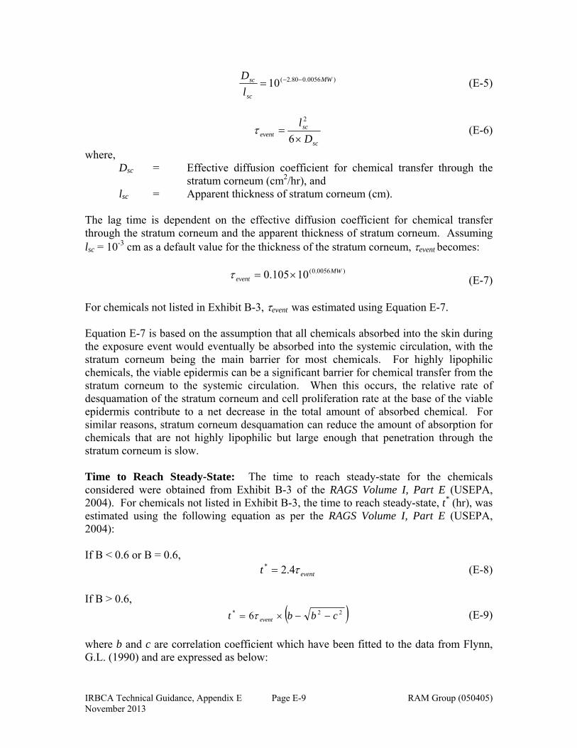
IRBCA Technical Guidance, Appendix E RAM Group (050405) November 2013
Page E-9
)0056.080.2(10 MW
sc
sc
l
D (E-5)
sc
scevent D
l
6
2
(E-6)
where, Dsc = Effective diffusion coefficient for chemical transfer through the
stratum corneum (cm2/hr), and lsc = Apparent thickness of stratum corneum (cm). The lag time is dependent on the effective diffusion coefficient for chemical transfer through the stratum corneum and the apparent thickness of stratum corneum. Assuming lsc = 10-3 cm as a default value for the thickness of the stratum corneum, event becomes:
)0056.0(10105.0 MW
event (E-7) For chemicals not listed in Exhibit B-3, event was estimated using Equation E-7. Equation E-7 is based on the assumption that all chemicals absorbed into the skin during the exposure event would eventually be absorbed into the systemic circulation, with the stratum corneum being the main barrier for most chemicals. For highly lipophilic chemicals, the viable epidermis can be a significant barrier for chemical transfer from the stratum corneum to the systemic circulation. When this occurs, the relative rate of desquamation of the stratum corneum and cell proliferation rate at the base of the viable epidermis contribute to a net decrease in the total amount of absorbed chemical. For similar reasons, stratum corneum desquamation can reduce the amount of absorption for chemicals that are not highly lipophilic but large enough that penetration through the stratum corneum is slow. Time to Reach Steady-State: The time to reach steady-state for the chemicals considered were obtained from Exhibit B-3 of the RAGS Volume I, Part E (USEPA, 2004). For chemicals not listed in Exhibit B-3, the time to reach steady-state, t* (hr), was estimated using the following equation as per the RAGS Volume I, Part E (USEPA, 2004): If B < 0.6 or B = 0.6, eventt 4.2* (E-8)
If B > 0.6,
22* 6 cbbt event (E-9)
where b and c are correlation coefficient which have been fitted to the data from Flynn, G.L. (1990) and are expressed as below:
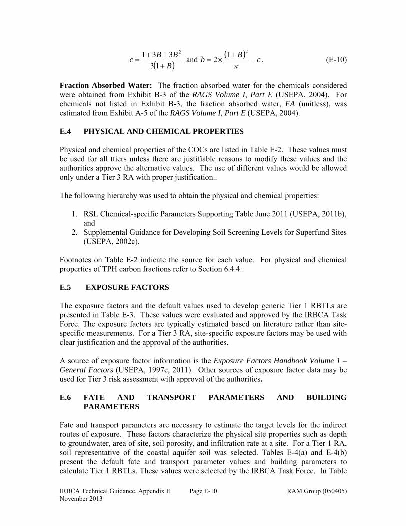
IRBCA Technical Guidance, Appendix E RAM Group (050405) November 2013
Page E-10
B
BBc
13
331 2
and
cB
b
212 . (E-10)
Fraction Absorbed Water: The fraction absorbed water for the chemicals considered were obtained from Exhibit B-3 of the RAGS Volume I, Part E (USEPA, 2004). For chemicals not listed in Exhibit B-3, the fraction absorbed water, FA (unitless), was estimated from Exhibit A-5 of the RAGS Volume I, Part E (USEPA, 2004). E.4 PHYSICAL AND CHEMICAL PROPERTIES Physical and chemical properties of the COCs are listed in Table E-2. These values must be used for all ttiers unless there are justifiable reasons to modify these values and the authorities approve the alternative values. The use of different values would be allowed only under a Tier 3 RA with proper justification.. The following hierarchy was used to obtain the physical and chemical properties:
1. RSL Chemical-specific Parameters Supporting Table June 2011 (USEPA, 2011b), and
2. Supplemental Guidance for Developing Soil Screening Levels for Superfund Sites (USEPA, 2002c).
Footnotes on Table E-2 indicate the source for each value. For physical and chemical properties of TPH carbon fractions refer to Section 6.4.4.. E.5 EXPOSURE FACTORS The exposure factors and the default values used to develop generic Tier 1 RBTLs are presented in Table E-3. These values were evaluated and approved by the IRBCA Task Force. The exposure factors are typically estimated based on literature rather than site-specific measurements. For a Tier 3 RA, site-specific exposure factors may be used with clear justification and the approval of the authorities. A source of exposure factor information is the Exposure Factors Handbook Volume 1 – General Factors (USEPA, 1997c, 2011). Other sources of exposure factor data may be used for Tier 3 risk assessment with approval of the authorities. E.6 FATE AND TRANSPORT PARAMETERS AND BUILDING
PARAMETERS Fate and transport parameters are necessary to estimate the target levels for the indirect routes of exposure. These factors characterize the physical site properties such as depth to groundwater, area of site, soil porosity, and infiltration rate at a site. For a Tier 1 RA, soil representative of the coastal aquifer soil was selected. Tables E-4(a) and E-4(b) present the default fate and transport parameter values and building parameters to calculate Tier 1 RBTLs. These values were selected by the IRBCA Task Force. In Table
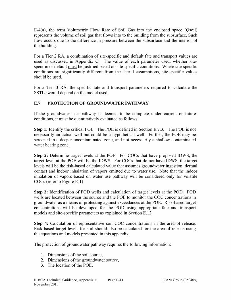
IRBCA Technical Guidance, Appendix E RAM Group (050405) November 2013
Page E-11
E-4(a), the term Volumetric Flow Rate of Soil Gas into the enclosed space (Qsoil) represents the volume of soil gas that flows into to the building from the subsurface. Such flow occurs due to the difference in pressure between the subsurface and the interior of the building. For a Tier 2 RA, a combination of site-specific and default fate and transport values are used as discussed in Appendix C. The value of each parameter used, whether site-specific or default must be justified based on site-specific conditions. Where site-specific conditions are significantly different from the Tier 1 assumptions, site-specific values should be used. For a Tier 3 RA, the specific fate and transport parameters required to calculate the SSTLs would depend on the model used. E.7 PROTECTION OF GROUNDWATER PATHWAY If the groundwater use pathway is deemed to be complete under current or future conditions, it must be quantitatively evaluated as follows: Step 1: Identify the critical POE. The POE is defined in Section E.7.3. The POE is not necessarily an actual well but could be a hypothetical well. Further, the POE may be screened in a deeper uncontaminated zone, and not necessarily a shallow contaminated water bearing zone. Step 2: Determine target levels at the POE. For COCs that have proposed IDWS, the target level at the POE will be the IDWS. For COCs that do not have IDWS, the target levels will be the risk-based calculated value that assumes groundwater ingestion, dermal contact and indoor inhalation of vapors emitted due to water use. Note that the indoor inhalation of vapors based on water use pathway will be considered only for volatile COCs (refer to Figure E-1) Step 3: Identification of POD wells and calculation of target levels at the POD. POD wells are located between the source and the POE to monitor the COC concentrations in groundwater as a means of protecting against exceedances at the POE. Risk-based target concentrations will be developed for the POD using appropriate fate and transport models and site-specific parameters as explained in Section E.12. Step 4: Calculation of representative soil COC concentrations in the area of release. Risk-based target levels for soil should also be calculated for the area of release using the equations and models presented in this appendix. The protection of groundwater pathway requires the following information:
1. Dimensions of the soil source, 2. Dimensions of the groundwater source, 3. The location of the POE,
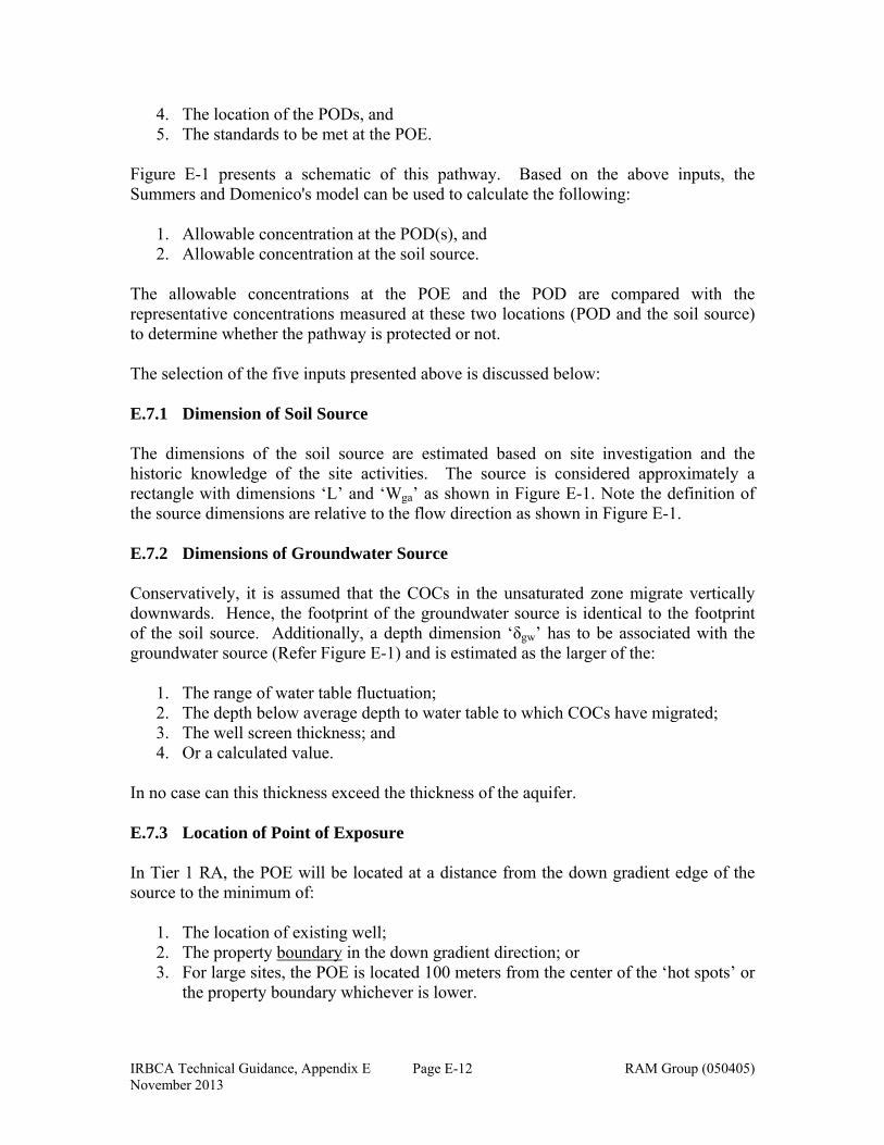
IRBCA Technical Guidance, Appendix E RAM Group (050405) November 2013
Page E-12
4. The location of the PODs, and 5. The standards to be met at the POE.
Figure E-1 presents a schematic of this pathway. Based on the above inputs, the Summers and Domenico's model can be used to calculate the following:
1. Allowable concentration at the POD(s), and 2. Allowable concentration at the soil source.
The allowable concentrations at the POE and the POD are compared with the representative concentrations measured at these two locations (POD and the soil source) to determine whether the pathway is protected or not. The selection of the five inputs presented above is discussed below: E.7.1 Dimension of Soil Source The dimensions of the soil source are estimated based on site investigation and the historic knowledge of the site activities. The source is considered approximately a rectangle with dimensions ‘L’ and ‘Wga’ as shown in Figure E-1. Note the definition of the source dimensions are relative to the flow direction as shown in Figure E-1. E.7.2 Dimensions of Groundwater Source Conservatively, it is assumed that the COCs in the unsaturated zone migrate vertically downwards. Hence, the footprint of the groundwater source is identical to the footprint of the soil source. Additionally, a depth dimension ‘δgw’ has to be associated with the groundwater source (Refer Figure E-1) and is estimated as the larger of the:
1. The range of water table fluctuation; 2. The depth below average depth to water table to which COCs have migrated; 3. The well screen thickness; and 4. Or a calculated value.
In no case can this thickness exceed the thickness of the aquifer. E.7.3 Location of Point of Exposure In Tier 1 RA, the POE will be located at a distance from the down gradient edge of the source to the minimum of:
1. The location of existing well; 2. The property boundary in the down gradient direction; or 3. For large sites, the POE is located 100 meters from the center of the ‘hot spots’ or
the property boundary whichever is lower.
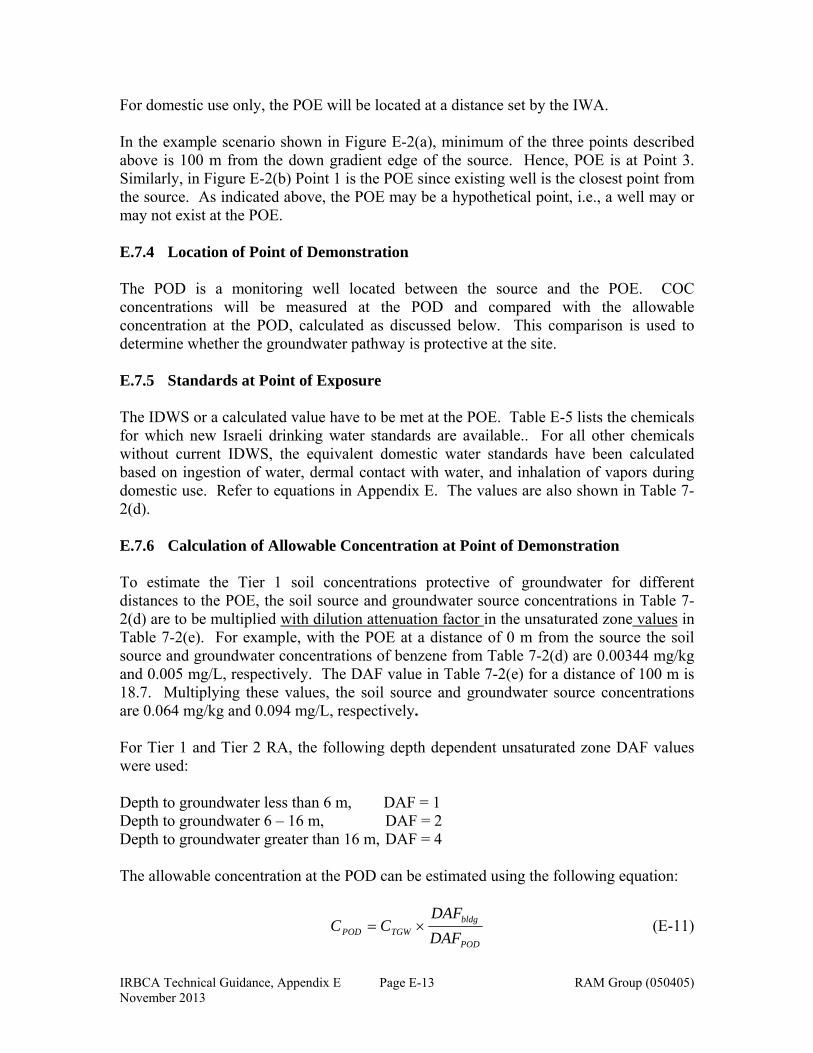
IRBCA Technical Guidance, Appendix E RAM Group (050405) November 2013
Page E-13
For domestic use only, the POE will be located at a distance set by the IWA. In the example scenario shown in Figure E-2(a), minimum of the three points described above is 100 m from the down gradient edge of the source. Hence, POE is at Point 3. Similarly, in Figure E-2(b) Point 1 is the POE since existing well is the closest point from the source. As indicated above, the POE may be a hypothetical point, i.e., a well may or may not exist at the POE. E.7.4 Location of Point of Demonstration The POD is a monitoring well located between the source and the POE. COC concentrations will be measured at the POD and compared with the allowable concentration at the POD, calculated as discussed below. This comparison is used to determine whether the groundwater pathway is protective at the site. E.7.5 Standards at Point of Exposure The IDWS or a calculated value have to be met at the POE. Table E-5 lists the chemicals for which new Israeli drinking water standards are available.. For all other chemicals without current IDWS, the equivalent domestic water standards have been calculated based on ingestion of water, dermal contact with water, and inhalation of vapors during domestic use. Refer to equations in Appendix E. The values are also shown in Table 7-2(d). E.7.6 Calculation of Allowable Concentration at Point of Demonstration To estimate the Tier 1 soil concentrations protective of groundwater for different distances to the POE, the soil source and groundwater source concentrations in Table 7-2(d) are to be multiplied with dilution attenuation factor in the unsaturated zone values in Table 7-2(e). For example, with the POE at a distance of 0 m from the source the soil source and groundwater concentrations of benzene from Table 7-2(d) are 0.00344 mg/kg and 0.005 mg/L, respectively. The DAF value in Table 7-2(e) for a distance of 100 m is 18.7. Multiplying these values, the soil source and groundwater source concentrations are 0.064 mg/kg and 0.094 mg/L, respectively.
For Tier 1 and Tier 2 RA, the following depth dependent unsaturated zone DAF values were used: Depth to groundwater less than 6 m, DAF = 1 Depth to groundwater 6 – 16 m, DAF = 2 Depth to groundwater greater than 16 m, DAF = 4 The allowable concentration at the POD can be estimated using the following equation:
POD
bldgTGWPOD DAF
DAFCC (E-11)
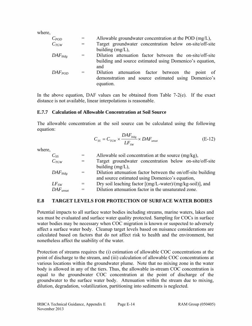
IRBCA Technical Guidance, Appendix E RAM Group (050405) November 2013
Page E-14
where, CPOD = Allowable groundwater concentration at the POD (mg/L), CTGW = Target groundwater concentration below on-site/off-site
building (mg/L), DAFbldg = Dilution attenuation factor between the on-site/off-site
building and source estimated using Domenico’s equation, and
DAFPOD = Dilution attenuation factor between the point of demonstration and source estimated using Domenico’s equation.
In the above equation, DAF values can be obtained from Table 7-2(e). If the exact distance is not available, linear interpolations is reasonable. E.7.7 Calculation of Allowable Concentration at Soil Source The allowable concentration at the soil source can be calculated using the following equation:
unsatSW
bldgTGWSS DAF
LF
DAFCC (E-12)
where, CSS = Allowable soil concentration at the source (mg/kg), CTGW = Target groundwater concentration below on-site/off-site
building (mg/L), DAFbldg = Dilution attenuation factor between the on/off-site building
and source estimated using Domenico’s equation, LFSW = Dry soil leaching factor [(mg/L-water)/(mg/kg-soil)], and DAFunsat = Dilution attenuation factor in the unsaturated zone.
E.8 TARGET LEVELS FOR PROTECTION OF SURFACE WATER BODIES Potential impacts to all surface water bodies including streams, marine waters, lakes and sea must be evaluated and surface water quality protected. Sampling for COCs in surface water bodies may be necessary when COC migration is known or suspected to adversely affect a surface water body. Cleanup target levels based on nuisance considerations are calculated based on factors that do not affect risk to health and the environment, but nonetheless affect the usability of the water. Protection of streams requires the (i) estimation of allowable COC concentrations at the point of discharge to the stream, and (iii) calculation of allowable COC concentrations at various locations within the groundwater plume. Note that no mixing zone in the water body is allowed in any of the tiers. Thus, the allowable in-stream COC concentration is equal to the groundwater COC concentration at the point of discharge of the groundwater to the surface water body. Attenuation within the stream due to mixing, dilution, degradation, volatilization, partitioning into sediments is neglected.
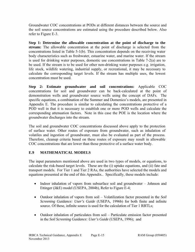
IRBCA Technical Guidance, Appendix E RAM Group (050405) November 2013
Page E-15
Groundwater COC concentrations at PODs at different distances between the source and the soil source concentrations are estimated using the procedure described below. Also refer to Figure E-3. Step 1: Determine the allowable concentration at the point of discharge to the stream: The allowable concentration at the point of discharge is selected from the concentrations listed in Table 5-1(b). This concentration depends on the receiving water body characteristics such as freshwater, estuarine water, and marine water. If the stream is used for drinking water purposes, domestic use concentrations in Table 7-2(a) are to be used. If the stream is to be used for other non-drinking water purposes e.g. irrigation, life stock, wildlife watering, industrial supply, or recreational, it may be necessary to calculate the corresponding target levels. If the stream has multiple uses, the lowest concentration must be used. Step 2: Estimate groundwater and soil concentrations: Applicable COC concentrations for soil and groundwater can be back-calculated at the point of demonstration wells and groundwater source wells using the concept of DAFs. The specific equations, a combination of the Summer and Domenico’s models, are presented in Appendix E. The procedure is similar to calculating the concentrations protective of a POD well in that it is necessary to establish one or more POD wells and calculate the corresponding attenuation factors. Note in this case the POE is the location where the groundwater discharges into the stream. The soil and groundwater COC concentrations discussed above apply to the protection of surface water. Other routes of exposure from groundwater, such as inhalation of volatiles and ingestion of groundwater, must also be evaluated as part of the process. Therefore, cleanup criteria based on these routes of exposure may result in allowable COC concentrations that are lower than those protective of a surface water body. E.9 MATHEMATICAL MODELS The input parameters mentioned above are used in two types of models, or equations, to calculate the risk-based target levels. These are the (i) uptake equations, and (ii) fate and transport models. For Tier 1 and Tier 2 RAs, the authorities have selected the models and equations presented at the end of this Appendix.. Specifically, these models include:
Indoor inhalation of vapors from subsurface soil and groundwater – Johnson and Ettinger (J&E) model (USEPA, 2004b), Refer to Figure E-4;
Outdoor inhalation of vapors from soil – Volatilization factor presented in the Soil Screening Guidance: User’s Guide (USEPA, 1996b) for both finite and infinite source. Of these, infinite source is used for the calculation of Tier 1 RBTLs;
Outdoor inhalation of particulates from soil – Particulate emission factor presented
in the Soil Screening Guidance: User’s Guide (USEPA, 1996); and
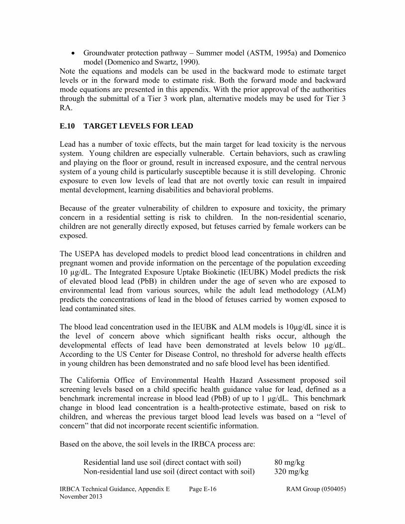
IRBCA Technical Guidance, Appendix E RAM Group (050405) November 2013
Page E-16
Groundwater protection pathway – Summer model (ASTM, 1995a) and Domenico model (Domenico and Swartz, 1990).
Note the equations and models can be used in the backward mode to estimate target levels or in the forward mode to estimate risk. Both the forward mode and backward mode equations are presented in this appendix. With the prior approval of the authorities through the submittal of a Tier 3 work plan, alternative models may be used for Tier 3 RA. E.10 TARGET LEVELS FOR LEAD Lead has a number of toxic effects, but the main target for lead toxicity is the nervous system. Young children are especially vulnerable. Certain behaviors, such as crawling and playing on the floor or ground, result in increased exposure, and the central nervous system of a young child is particularly susceptible because it is still developing. Chronic exposure to even low levels of lead that are not overtly toxic can result in impaired mental development, learning disabilities and behavioral problems. Because of the greater vulnerability of children to exposure and toxicity, the primary concern in a residential setting is risk to children. In the non-residential scenario, children are not generally directly exposed, but fetuses carried by female workers can be exposed. The USEPA has developed models to predict blood lead concentrations in children and pregnant women and provide information on the percentage of the population exceeding 10 µg/dL. The Integrated Exposure Uptake Biokinetic (IEUBK) Model predicts the risk of elevated blood lead (PbB) in children under the age of seven who are exposed to environmental lead from various sources, while the adult lead methodology (ALM) predicts the concentrations of lead in the blood of fetuses carried by women exposed to lead contaminated sites. The blood lead concentration used in the IEUBK and ALM models is 10µg/dL since it is the level of concern above which significant health risks occur, although the developmental effects of lead have been demonstrated at levels below 10 µg/dL. According to the US Center for Disease Control, no threshold for adverse health effects in young children has been demonstrated and no safe blood level has been identified. The California Office of Environmental Health Hazard Assessment proposed soil screening levels based on a child specific health guidance value for lead, defined as a benchmark incremental increase in blood lead (PbB) of up to 1 μg/dL. This benchmark change in blood lead concentration is a health-protective estimate, based on risk to children, and whereas the previous target blood lead levels was based on a “level of concern” that did not incorporate recent scientific information. Based on the above, the soil levels in the IRBCA process are:
Residential land use soil (direct contact with soil) 80 mg/kg Non-residential land use soil (direct contact with soil) 320 mg/kg
IRBCA Technical Guidance, Appendix E RAM Group (050405) November 2013
Page E-17
The RP can choose to perform a site specific (Tier 3) RA for lead if concentrations exceed these levels. The above soil concentrations do not account for leaching to groundwater. At sites where this pathway is complete or potentially complete, the authorities may require a site-specific analysis. The use of a leaching test using water with a pH similar to that of infiltrating water may be used to determine the potential for lead to impact groundwater. E.11 TARGET LEVEL CALCULATION FOR LNAPL OR DNAPL The IRBCA process allows for the calculation of risk and target levels when LNAPL or DNAPL is present. Under this condition, the primary routes of exposure are indoor inhalation for a residential or a non-residential receptor, and the protection of a current or potential future POE groundwater well. For these pathways, the key step is the calculation of the vapor concentration and the dissolved concentration emanating from the LNAPL and/or DNAPL. Once these concentrations have been estimated, risk and target levels can be determined using the procedures presented in Sections E.2 to E.8 above. The soil vapor concentration in equilibrium with LNAPL or DNAPL is the effective soil vapor concentration. This concentration depends on (i) the chemical-specific saturated soil vapor concentration, and (ii) the mole fraction of the chemical in the LNAPL or DNAPL for which the soil vapor concentration is being calculated. If the mole fraction of a COC is not known, default mole fractions, calculated using the weight fraction of a specific COC in the LNAPL or DNAPL, may be used if the NAPL can be analyzed and its components determined. Alternatively, the evaluator may sample the LNAPL/DNAPL for laboratory analysis to determine site-specific values for the weight and mole fractions. The specific equations used to calculate the effective soil vapor or effective dissolved concentrations are presented in Appendix E. In the forward mode of risk assessment, the effective soil vapor and dissolved concentrations can be used to calculate the risk due to indoor inhalation or to estimate the concentration at the POD and POE wells. If DNAPL is located below the water table, pathways related to inhalation of vapors generated from the DNAPL will be considered incomplete, as vapors will not penetrate the overlying column of saturated soil. E.12 REFERENCES FDEP, 2005. Technical Report: Development of Cleanup Target Levels (CTLs) For Chapter 62-777, F.A.C. Division of Waste Management, Florida Department of Environmental Protection, February 2005. Flynn, G.L., 1990. Physicochemical Determinates of Skin Absorption. In T.R. Gerrity and C.J. Henry, Eds. Principles of Route-to-Route Extrapolation for Risk Assessment, Elsevier, New York. p. 93 – 127.
IRBCA Technical Guidance, Appendix E RAM Group (050405) November 2013
Page E-18
USEPA, 1989. Risk Assessment Guidance for Superfund (RAGS), Volume 1: Human Health Evaluation Manual, Part A. EPA/540/1-89/002. December 1989. USEPA, 1996c. Recommendations of the Technical Review Workgroup for Lead for an Interim Approach to Assessing Risks Associated with Adult Exposures to Lead in Soil. U.S. Environmental Protection Agency Technical Review Workgroup for Lead. December 1996. USEPA, 1999b. Overview of the IEUBK Model for Lead in Children. OSWER 92857-31. Office of Emergency and Remedial Response. EPA 540-R-99-015. PB99-963508. August 1999. USEPA, 2000a. Methodology for Deriving Ambient Water Quality Criteria for the Protection of Human Health. Office of Water, Washington, DC. USEPA, 2004. Risk Assessment Guidance for Superfund (RAGS), Volume 1: Human Health Evaluation Manual, Part E Supplemental Guidance for Dermal Risk Assessment. EPA/540/R/99/005. July 2004.
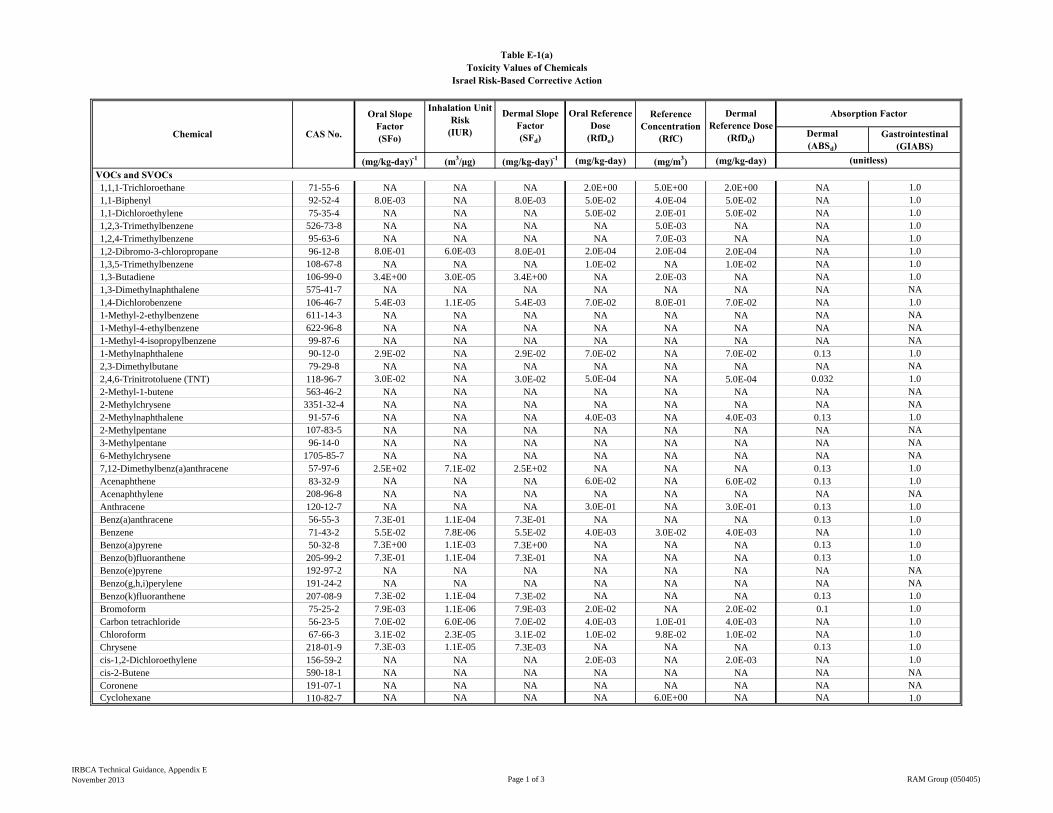
Dermal(ABSd)
Gastrointestinal(GIABS)
(mg/kg-day)-1 (m3/μg) (mg/kg-day)-1 (mg/kg-day) (mg/m3) (mg/kg-day) VOCs and SVOCs
1,1,1-Trichloroethane 71-55-6 NA NA NA 2.0E+00 5.0E+00 2.0E+00 NA 1.01,1-Biphenyl 92-52-4 8.0E-03 NA 8.0E-03 5.0E-02 4.0E-04 5.0E-02 NA 1.01,1-Dichloroethylene 75-35-4 NA NA NA 5.0E-02 2.0E-01 5.0E-02 NA 1.01,2,3-Trimethylbenzene 526-73-8 NA NA NA NA 5.0E-03 NA NA 1.01,2,4-Trimethylbenzene 95-63-6 NA NA NA NA 7.0E-03 NA NA 1.01,2-Dibromo-3-chloropropane 96-12-8 8.0E-01 6.0E-03 8.0E-01 2.0E-04 2.0E-04 2.0E-04 NA 1.01,3,5-Trimethylbenzene 108-67-8 NA NA NA 1.0E-02 NA 1.0E-02 NA 1.01,3-Butadiene 106-99-0 3.4E+00 3.0E-05 3.4E+00 NA 2.0E-03 NA NA 1.01,3-Dimethylnaphthalene 575-41-7 NA NA NA NA NA NA NA NA1,4-Dichlorobenzene 106-46-7 5.4E-03 1.1E-05 5.4E-03 7.0E-02 8.0E-01 7.0E-02 NA 1.01-Methyl-2-ethylbenzene 611-14-3 NA NA NA NA NA NA NA NA1-Methyl-4-ethylbenzene 622-96-8 NA NA NA NA NA NA NA NA1-Methyl-4-isopropylbenzene 99-87-6 NA NA NA NA NA NA NA NA1-Methylnaphthalene 90-12-0 2.9E-02 NA 2.9E-02 7.0E-02 NA 7.0E-02 0.13 1.02,3-Dimethylbutane 79-29-8 NA NA NA NA NA NA NA NA2,4,6-Trinitrotoluene (TNT) 118-96-7 3.0E-02 NA 3.0E-02 5.0E-04 NA 5.0E-04 0.032 1.02-Methyl-1-butene 563-46-2 NA NA NA NA NA NA NA NA2-Methylchrysene 3351-32-4 NA NA NA NA NA NA NA NA2-Methylnaphthalene 91-57-6 NA NA NA 4.0E-03 NA 4.0E-03 0.13 1.02-Methylpentane 107-83-5 NA NA NA NA NA NA NA NA3-Methylpentane 96-14-0 NA NA NA NA NA NA NA NA6-Methylchrysene 1705-85-7 NA NA NA NA NA NA NA NA7,12-Dimethylbenz(a)anthracene 57-97-6 2.5E+02 7.1E-02 2.5E+02 NA NA NA 0.13 1.0Acenaphthene 83-32-9 NA NA NA 6.0E-02 NA 6.0E-02 0.13 1.0Acenaphthylene 208-96-8 NA NA NA NA NA NA NA NAAnthracene 120-12-7 NA NA NA 3.0E-01 NA 3.0E-01 0.13 1.0Benz(a)anthracene 56-55-3 7.3E-01 1.1E-04 7.3E-01 NA NA NA 0.13 1.0Benzene 71-43-2 5.5E-02 7.8E-06 5.5E-02 4.0E-03 3.0E-02 4.0E-03 NA 1.0Benzo(a)pyrene 50-32-8 7.3E+00 1.1E-03 7.3E+00 NA NA NA 0.13 1.0Benzo(b)fluoranthene 205-99-2 7.3E-01 1.1E-04 7.3E-01 NA NA NA 0.13 1.0Benzo(e)pyrene 192-97-2 NA NA NA NA NA NA NA NABenzo(g,h,i)perylene 191-24-2 NA NA NA NA NA NA NA NABenzo(k)fluoranthene 207-08-9 7.3E-02 1.1E-04 7.3E-02 NA NA NA 0.13 1.0Bromoform 75-25-2 7.9E-03 1.1E-06 7.9E-03 2.0E-02 NA 2.0E-02 0.1 1.0Carbon tetrachloride 56-23-5 7.0E-02 6.0E-06 7.0E-02 4.0E-03 1.0E-01 4.0E-03 NA 1.0Chloroform 67-66-3 3.1E-02 2.3E-05 3.1E-02 1.0E-02 9.8E-02 1.0E-02 NA 1.0Chrysene 218-01-9 7.3E-03 1.1E-05 7.3E-03 NA NA NA 0.13 1.0cis-1,2-Dichloroethylene 156-59-2 NA NA NA 2.0E-03 NA 2.0E-03 NA 1.0cis-2-Butene 590-18-1 NA NA NA NA NA NA NA NACoronene 191-07-1 NA NA NA NA NA NA NA NACyclohexane 110-82-7 NA NA NA NA 6.0E+00 NA NA 1.0
(unitless)
Reference Concentration
(RfC)
Dermal Reference Dose
(RfDd)
Inhalation Unit Risk
(IUR)
Table E-1(a)
Israel Risk-Based Corrective Action
Absorption Factor
Chemical
Oral Slope Factor(SFo)
Dermal Slope Factor (SFd)
Toxicity Values of Chemicals
Oral Reference Dose
(RfDo)CAS No.
IRBCA Technical Guidance, Appendix ENovember 2013 Page 1 of 3 RAM Group (050405)
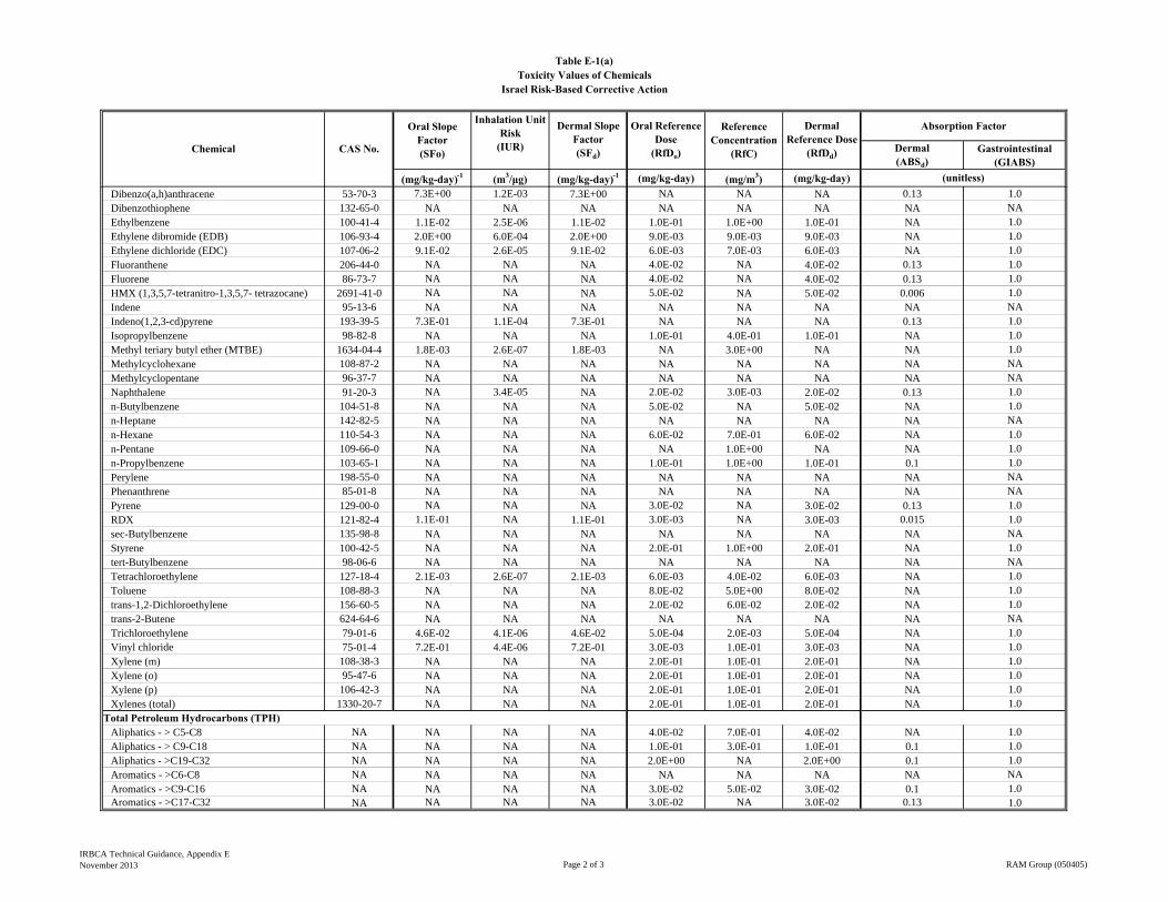
Dermal(ABSd)
Gastrointestinal(GIABS)
(mg/kg-day)-1 (m3/μg) (mg/kg-day)-1 (mg/kg-day) (mg/m3) (mg/kg-day) (unitless)
Reference Concentration
(RfC)
Dermal Reference Dose
(RfDd)
Inhalation Unit Risk
(IUR)
Table E-1(a)
Israel Risk-Based Corrective Action
Absorption Factor
Chemical
Oral Slope Factor(SFo)
Dermal Slope Factor (SFd)
Toxicity Values of Chemicals
Oral Reference Dose
(RfDo)CAS No.
Dibenzo(a,h)anthracene 53-70-3 7.3E+00 1.2E-03 7.3E+00 NA NA NA 0.13 1.0Dibenzothiophene 132-65-0 NA NA NA NA NA NA NA NAEthylbenzene 100-41-4 1.1E-02 2.5E-06 1.1E-02 1.0E-01 1.0E+00 1.0E-01 NA 1.0Ethylene dibromide (EDB) 106-93-4 2.0E+00 6.0E-04 2.0E+00 9.0E-03 9.0E-03 9.0E-03 NA 1.0Ethylene dichloride (EDC) 107-06-2 9.1E-02 2.6E-05 9.1E-02 6.0E-03 7.0E-03 6.0E-03 NA 1.0Fluoranthene 206-44-0 NA NA NA 4.0E-02 NA 4.0E-02 0.13 1.0Fluorene 86-73-7 NA NA NA 4.0E-02 NA 4.0E-02 0.13 1.0HMX (1,3,5,7-tetranitro-1,3,5,7- tetrazocane) 2691-41-0 NA NA NA 5.0E-02 NA 5.0E-02 0.006 1.0Indene 95-13-6 NA NA NA NA NA NA NA NAIndeno(1,2,3-cd)pyrene 193-39-5 7.3E-01 1.1E-04 7.3E-01 NA NA NA 0.13 1.0Isopropylbenzene 98-82-8 NA NA NA 1.0E-01 4.0E-01 1.0E-01 NA 1.0Methyl teriary butyl ether (MTBE) 1634-04-4 1.8E-03 2.6E-07 1.8E-03 NA 3.0E+00 NA NA 1.0Methylcyclohexane 108-87-2 NA NA NA NA NA NA NA NAMethylcyclopentane 96-37-7 NA NA NA NA NA NA NA NANaphthalene 91-20-3 NA 3.4E-05 NA 2.0E-02 3.0E-03 2.0E-02 0.13 1.0n-Butylbenzene 104-51-8 NA NA NA 5.0E-02 NA 5.0E-02 NA 1.0n-Heptane 142-82-5 NA NA NA NA NA NA NA NAn-Hexane 110-54-3 NA NA NA 6.0E-02 7.0E-01 6.0E-02 NA 1.0n-Pentane 109-66-0 NA NA NA NA 1.0E+00 NA NA 1.0n-Propylbenzene 103-65-1 NA NA NA 1.0E-01 1.0E+00 1.0E-01 0.1 1.0Perylene 198-55-0 NA NA NA NA NA NA NA NAPhenanthrene 85-01-8 NA NA NA NA NA NA NA NAPyrene 129-00-0 NA NA NA 3.0E-02 NA 3.0E-02 0.13 1.0RDX 121-82-4 1.1E-01 NA 1.1E-01 3.0E-03 NA 3.0E-03 0.015 1.0sec-Butylbenzene 135-98-8 NA NA NA NA NA NA NA NAStyrene 100-42-5 NA NA NA 2.0E-01 1.0E+00 2.0E-01 NA 1.0tert-Butylbenzene 98-06-6 NA NA NA NA NA NA NA NATetrachloroethylene 127-18-4 2.1E-03 2.6E-07 2.1E-03 6.0E-03 4.0E-02 6.0E-03 NA 1.0Toluene 108-88-3 NA NA NA 8.0E-02 5.0E+00 8.0E-02 NA 1.0trans-1,2-Dichloroethylene 156-60-5 NA NA NA 2.0E-02 6.0E-02 2.0E-02 NA 1.0trans-2-Butene 624-64-6 NA NA NA NA NA NA NA NATrichloroethylene 79-01-6 4.6E-02 4.1E-06 4.6E-02 5.0E-04 2.0E-03 5.0E-04 NA 1.0Vinyl chloride 75-01-4 7.2E-01 4.4E-06 7.2E-01 3.0E-03 1.0E-01 3.0E-03 NA 1.0Xylene (m) 108-38-3 NA NA NA 2.0E-01 1.0E-01 2.0E-01 NA 1.0Xylene (o) 95-47-6 NA NA NA 2.0E-01 1.0E-01 2.0E-01 NA 1.0Xylene (p) 106-42-3 NA NA NA 2.0E-01 1.0E-01 2.0E-01 NA 1.0Xylenes (total) 1330-20-7 NA NA NA 2.0E-01 1.0E-01 2.0E-01 NA 1.0
Total Petroleum Hydrocarbons (TPH)Aliphatics - > C5-C8 NA NA NA NA 4.0E-02 7.0E-01 4.0E-02 NA 1.0Aliphatics - > C9-C18 NA NA NA NA 1.0E-01 3.0E-01 1.0E-01 0.1 1.0Aliphatics - >C19-C32 NA NA NA NA 2.0E+00 NA 2.0E+00 0.1 1.0Aromatics - >C6-C8 NA NA NA NA NA NA NA NA NAAromatics - >C9-C16 NA NA NA NA 3.0E-02 5.0E-02 3.0E-02 0.1 1.0Aromatics - >C17-C32 NA NA NA NA 3.0E-02 NA 3.0E-02 0.13 1.0
IRBCA Technical Guidance, Appendix ENovember 2013 Page 2 of 3 RAM Group (050405)
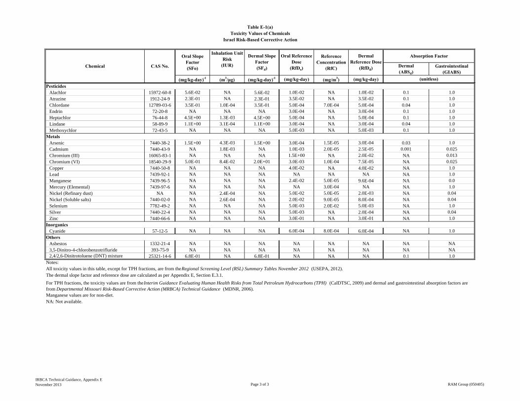
Dermal(ABSd)
Gastrointestinal(GIABS)
(mg/kg-day)-1 (m3/μg) (mg/kg-day)-1 (mg/kg-day) (mg/m3) (mg/kg-day) (unitless)
Reference Concentration
(RfC)
Dermal Reference Dose
(RfDd)
Inhalation Unit Risk
(IUR)
Table E-1(a)
Israel Risk-Based Corrective Action
Absorption Factor
Chemical
Oral Slope Factor(SFo)
Dermal Slope Factor (SFd)
Toxicity Values of Chemicals
Oral Reference Dose
(RfDo)CAS No.
PesticidesAlachlor 15972-60-8 5.6E-02 NA 5.6E-02 1.0E-02 NA 1.0E-02 0.1 1.0Atrazine 1912-24-9 2.3E-01 NA 2.3E-01 3.5E-02 NA 3.5E-02 0.1 1.0Chlordane 12789-03-6 3.5E-01 1.0E-04 3.5E-01 5.0E-04 7.0E-04 5.0E-04 0.04 1.0Endrin 72-20-8 NA NA NA 3.0E-04 NA 3.0E-04 0.1 1.0Heptachlor 76-44-8 4.5E+00 1.3E-03 4.5E+00 5.0E-04 NA 5.0E-04 0.1 1.0Lindane 58-89-9 1.1E+00 3.1E-04 1.1E+00 3.0E-04 NA 3.0E-04 0.04 1.0Methoxychlor 72-43-5 NA NA NA 5.0E-03 NA 5.0E-03 0.1 1.0
MetalsArsenic 7440-38-2 1.5E+00 4.3E-03 1.5E+00 3.0E-04 1.5E-05 3.0E-04 0.03 1.0Cadmium 7440-43-9 NA 1.8E-03 NA 1.0E-03 2.0E-05 2.5E-05 0.001 0.025Chromium (III) 16065-83-1 NA NA NA 1.5E+00 NA 2.0E-02 NA 0.013Chromium (VI) 18540-29-9 5.0E-01 8.4E-02 2.0E+01 3.0E-03 1.0E-04 7.5E-05 NA 0.025Copper 7440-50-8 NA NA NA 4.0E-02 NA 4.0E-02 NA 1.0Lead 7439-92-1 NA NA NA NA NA NA NA 1.0Manganese 7439-96-5 NA NA NA 2.4E-02 5.0E-05 9.6E-04 NA 0.0Mercury (Elemental) 7439-97-6 NA NA NA NA 3.0E-04 NA NA 1.0Nickel (Refinary dust) NA NA 2.4E-04 NA 5.0E-02 5.0E-05 2.0E-03 NA 0.04Nickel (Soluble salts) 7440-02-0 NA 2.6E-04 NA 2.0E-02 9.0E-05 8.0E-04 NA 0.04Selenium 7782-49-2 NA NA NA 5.0E-03 2.0E-02 5.0E-03 NA 1.0Silver 7440-22-4 NA NA NA 5.0E-03 NA 2.0E-04 NA 0.04Zinc 7440-66-6 NA NA NA 3.0E-01 NA 3.0E-01 NA 1.0
InorganicsCyanide 57-12-5 NA NA NA 6.0E-04 8.0E-04 6.0E-04 NA 1.0
OthersAsbestos 1332-21-4 NA NA NA NA NA NA NA NA3,5-Dinitro-4-chlorobenzotrifluride 393-75-9 NA NA NA NA NA NA NA NA2,4/2,6-Dinitrotoluene (DNT) mixture 25321-14-6 6.8E-01 NA 6.8E-01 NA NA NA 0.1 1.0
Notes:All toxicity values in this table, except for TPH fractions, are from the Regional Screening Level (RSL) Summary Tables November 2012 (USEPA, 2012).The dermal slope factor and reference dose are calculated as per Appendix E, Section E.3.1.
Manganese values are for non-diet.NA: Not available.
For TPH fractions, the toxicity values are from the Interim Guidance Evaluating Human Health Risks from Total Petroleum Hydrocarbons (TPH) (CalDTSC, 2009) and dermal and gastrointestinal absorption factors are from Departmental Missouri Risk-Based Corrective Action (MRBCA) Technical Guidance (MDNR, 2006).
IRBCA Technical Guidance, Appendix ENovember 2013 Page 3 of 3 RAM Group (050405)
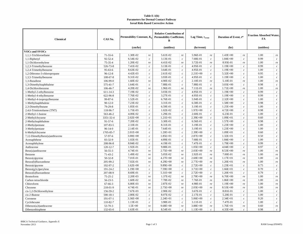
VOCs and SVOCs1,1,1-Trichloroethane 71-55-6 1.30E-02 re 5.61E-02 re 5.96E-01 re 1.43E+00 re 1.00 re1,1-Biphenyl 92-52-4 6.54E-02 c 3.13E-01 c 7.68E-01 c 1.84E+00 c 0.99 c1,1-Dichloroethylene 75-35-4 1.20E-02 re 4.41E-02 re 3.72E-01 re 8.93E-01 re 1.00 re1,2,3-Trimethylbenzene 526-73-8 7.41E-02 c 3.13E-01 c 4.95E-01 c 1.19E+00 c 0.99 c1,2,4-Trimethylbenzene 95-63-6 8.63E-02 c 3.64E-01 c 4.95E-01 c 1.19E+00 c 1.00 c1,2-Dibromo-3-chloropropane 96-12-8 4.42E-03 c 2.61E-02 c 2.21E+00 c 5.32E+00 c 0.95 c1,3,5-Trimethylbenzene 108-67-8 9.31E-02 c 3.93E-01 c 4.95E-01 c 1.19E+00 c 1.00 c1,3-Butadiene 106-99-0 1.60E-02 re 4.90E-02 c 2.10E-01 re 5.10E-01 re 1.00 re1,3-Dimethylnaphthalene 575-41-7 1.64E-01 c 7.88E-01 c 7.88E-01 c 3.03E+00 c 0.98 c1,4-Dichlorobenzene 106-46-7 4.20E-02 re 1.96E-01 re 7.11E-01 re 1.71E+00 re 1.00 re1-Methyl-2-ethylbenzene 611-14-3 7.19E-02 c 3.03E-01 c 4.95E-01 c 1.19E+00 c 0.99 c1-Methyl-4-ethylbenzene 622-96-8 7.76E-02 c 3.27E-01 c 4.95E-01 c 1.19E+00 c 0.99 c1-Methyl-4-isopropylbenzene 99-87-6 1.52E-01 c 6.76E-01 c 5.94E-01 c 2.32E+00 c 1.00 c1-Methylnaphthalene 90-12-0 7.23E-02 c 3.31E-01 c 6.58E-01 c 1.58E+00 c 0.98 c2,3-Dimethylbutane 79-29-8 1.85E-01 c 6.59E-01 c 3.19E-01 c 1.25E+00 c 1.00 c2,4,6-Trinitrotoluene (TNT) 118-96-7 1.75E-03 c 1.02E-02 c 1.97E+00 c 4.72E+00 c 0.98 c2-Methyl-1-butene 563-46-2 4.00E-02 c 1.29E-01 c 2.60E-01 c 6.23E-01 c 1.00 c2-Methylchrysene 3351-32-4 2.02E+00 c 1.21E+01 c 2.39E+00 c 1.09E+01 c 0.60 c2-Methylnaphthalene 91-57-6 7.20E-02 c 3.30E-01 c 6.56E-01 c 1.57E+00 c 0.98 c2-Methylpentane 107-83-5 2.33E-01 c 8.31E-01 c 3.19E-01 c 1.23E+00 c 1.00 c3-Methylpentane 96-14-0 2.14E-01 c 7.64E-01 c 3.19E-01 c 1.23E+00 c 1.00 c6-Methylchrysene 1705-85-7 2.01E+00 c 1.20E+01 c 2.39E+00 c 1.09E+01 c 0.60 c7,12-Dimethylbenz(a)anthracene 57-97-6 3.00E+00 c 1.85E+01 c 2.87E+00 c 1.32E+01 c 0.50 cAcenaphthene 83-32-9 1.02E-01 c 4.89E-01 c 7.68E-01 c 1.84E+00 c 1.00 cAcenaphthylene 208-96-8 8.84E-02 c 4.19E-01 c 7.47E-01 c 1.79E+00 c 0.99 cAnthracene 120-12-7 1.92E-01 c 9.88E-01 c 1.05E+00 c 4.04E+00 c 0.97 cBenz(a)anthracene 56-55-3 4.74E-01 re 2.75E+00 re 2.03E+00 re 8.53E+00 re 1.00 reBenzene 71-43-2 1.49E-02 re 5.05E-02 re 2.92E-01 re 7.00E-01 re 1.00 reBenzo(a)pyrene 50-32-8 7.01E-01 re 4.27E+00 re 2.69E+00 re 1.17E+01 re 1.00 reBenzo(b)fluoranthene 205-99-2 7.02E-01 re 4.29E+00 re 2.77E+00 re 1.20E+01 re 1.00 reBenzo(e)pyrene 192-97-2 1.62E+00 c 9.89E+00 c 2.72E+00 c 1.23E+01 c 0.75 cBenzo(g,h,i)perylene 191-24-2 1.19E+00 c 7.59E+00 c 3.71E+00 c 1.66E+01 c 0.70 cBenzo(k)fluoranthene 207-08-9 8.69E-01 c 5.31E+00 c 2.72E+00 c 1.20E+01 c 0.79 cBromoform 75-25-2 2.20E-03 re 1.37E-02 re 2.79E+00 re 6.70E+00 re 1.00 reCarbon tetrachloride 56-23-5 1.60E-02 re 7.78E-02 re 7.76E-01 re 1.86E+00 re 1.00 reChloroform 67-66-3 6.80E-03 re 2.87E-02 re 4.98E-01 re 1.19E+00 re 1.00 reChrysene 218-01-9 4.74E-01 re 2.75E+00 re 2.03E+00 re 8.53E+00 re 1.00 recis-1,2-Dichloroethylene 156-59-2 7.67E-03 c 2.90E-02 c 3.67E-01 c 8.81E-01 c 1.00 ccis-2-Butene 590-18-1 2.80E-02 c 8.07E-02 c 2.17E-01 c 5.20E-01 c 1.00 cCoronene 191-07-1 3.36E+00 c 2.24E+01 c 5.06E+00 c 2.34E+01 c 0.20 cCyclohexane 110-82-7 1.13E-01 c 3.98E-01 c 3.11E-01 c 7.47E-01 c 1.00 cDibenzo(a,h)anthracene 53-70-3 1.5E+00 re 9.68E+00 re 3.88E+00 re 1.76E+01 re 0.60 reDibenzothiophene 132-65-0 1.63E-01 c 8.54E-01 c 1.13E+00 c 4.35E+00 c 0.98 c
Fraction Absorbed Water, FA
(cm/hr) (unitless) (hr/event) (hr) (unitless)
Permeability Constant, Kp
Relative Contribution of Permeability Coefficient,
BLag Time,event Duration of Event, t*
Table E-1(b)Parameters for Dermal Contact Pathway
Isreal Risk-Based Corrective Action
Chemical CAS No.
IRBCA Technical Guidance, Appendix ENovember 2013 Page 1 of 3 RAM Group (050405)
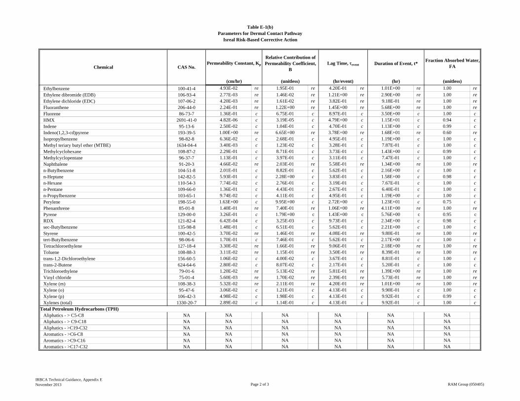
Fraction Absorbed Water, FA
(cm/hr) (unitless) (hr/event) (hr) (unitless)
Permeability Constant, Kp
Relative Contribution of Permeability Coefficient,
BLag Time,event Duration of Event, t*
Table E-1(b)Parameters for Dermal Contact Pathway
Isreal Risk-Based Corrective Action
Chemical CAS No.
Ethylbenzene 100-41-4 4.93E-02 re 1.95E-01 re 4.20E-01 re 1.01E+00 re 1.00 re
Ethylene dibromide (EDB) 106-93-4 2.77E-03 re 1.46E-02 re 1.21E+00 re 2.90E+00 re 1.00 reEthylene dichloride (EDC) 107-06-2 4.20E-03 re 1.61E-02 re 3.82E-01 re 9.18E-01 re 1.00 reFluoranthene 206-44-0 2.24E-01 re 1.22E+00 re 1.45E+00 re 5.68E+00 re 1.00 reFluorene 86-73-7 1.36E-01 c 6.75E-01 c 8.97E-01 c 3.50E+00 c 1.00 cHMX 2691-41-0 4.82E-06 c 3.19E-05 c 4.79E+00 c 1.15E+01 c 0.94 cIndene 95-13-6 2.50E-02 c 1.04E-01 c 4.70E-01 c 1.13E+00 c 0.99 cIndeno(1,2,3-cd)pyrene 193-39-5 1.00E+00 re 6.65E+00 re 3.78E+00 re 1.68E+01 re 0.60 reIsopropylbenzene 98-82-8 6.36E-02 c 2.68E-01 c 4.95E-01 c 1.19E+00 c 1.00 cMethyl teriary butyl ether (MTBE) 1634-04-4 3.40E-03 c 1.23E-02 c 3.28E-01 c 7.87E-01 c 1.00 cMethylcyclohexane 108-87-2 2.29E-01 c 8.71E-01 c 3.73E-01 c 1.43E+00 c 0.99 cMethylcyclopentane 96-37-7 1.13E-01 c 3.97E-01 c 3.11E-01 c 7.47E-01 c 1.00 cNaphthalene 91-20-3 4.66E-02 re 2.03E-01 re 5.58E-01 re 1.34E+00 re 1.00 ren-Butylbenzene 104-51-8 2.01E-01 c 8.82E-01 c 5.62E-01 c 2.16E+00 c 1.00 cn-Heptane 142-82-5 5.93E-01 c 2.28E+00 c 3.83E-01 c 1.58E+00 c 0.98 cn-Hexane 110-54-3 7.74E-02 c 2.76E-01 c 3.19E-01 c 7.67E-01 c 1.00 cn-Pentane 109-66-0 1.36E-01 c 4.43E-01 c 2.67E-01 c 6.40E-01 c 1.00 cn-Propylbenzene 103-65-1 9.74E-02 c 4.11E-01 c 4.95E-01 c 1.19E+00 c 1.00 cPerylene 198-55-0 1.63E+00 c 9.95E+00 c 2.72E+00 c 1.23E+01 c 0.75 cPhenanthrene 85-01-8 1.40E-01 re 7.40E-01 re 1.06E+00 re 4.11E+00 re 1.00 rePyrene 129-00-0 3.26E-01 c 1.79E+00 c 1.43E+00 c 5.76E+00 c 0.95 cRDX 121-82-4 6.42E-04 c 3.25E-03 c 9.73E-01 c 2.34E+00 c 0.98 csec-Butylbenzene 135-98-8 1.48E-01 c 6.51E-01 c 5.62E-01 c 2.21E+00 c 1.00 cStyrene 100-42-5 3.70E-02 re 1.46E-01 re 4.08E-01 re 9.80E-01 re 1.00 retert-Butylbenzene 98-06-6 1.70E-01 c 7.46E-01 c 5.62E-01 c 2.17E+00 c 1.00 cTetrachloroethylene 127-18-4 3.30E-02 re 1.66E-01 re 9.06E-01 re 2.18E+00 re 1.00 reToluene 108-88-3 3.11E-02 re 1.15E-01 re 3.50E-01 re 8.39E-01 re 1.00 retrans-1,2-Dichloroethylene 156-60-5 1.06E-02 c 4.00E-02 c 3.67E-01 c 8.81E-01 c 1.00 ctrans-2-Butene 624-64-6 2.80E-02 c 8.07E-02 c 2.17E-01 c 5.20E-01 c 1.00 cTrichloroethylene 79-01-6 1.20E-02 re 5.13E-02 re 5.81E-01 re 1.39E+00 re 1.00 reVinyl chloride 75-01-4 5.60E-03 re 1.70E-02 re 2.39E-01 re 5.73E-01 re 1.00 reXylene (m) 108-38-3 5.32E-02 re 2.11E-01 re 4.20E-01 re 1.01E+00 re 1.00 reXylene (o) 95-47-6 3.06E-02 c 1.21E-01 c 4.13E-01 c 9.90E-01 c 1.00 cXylene (p) 106-42-3 4.98E-02 c 1.98E-01 c 4.13E-01 c 9.92E-01 c 0.99 cXylenes (total) 1330-20-7 2.89E-02 c 1.14E-01 c 4.13E-01 c 9.92E-01 c 1.00 c
Total Petroleum Hydrocarbons (TPH)Aliphatics - > C5-C8 NA NA NA NA NA NAAliphatics - > C9-C18 NA NA NA NA NA NAAliphatics - >C19-C32 NA NA NA NA NA NAAromatics - >C6-C8 NA NA NA NA NA NAAromatics - >C9-C16 NA NA NA NA NA NAAromatics - >C17-C32 NA NA NA NA NA NA
IRBCA Technical Guidance, Appendix ENovember 2013 Page 2 of 3 RAM Group (050405)
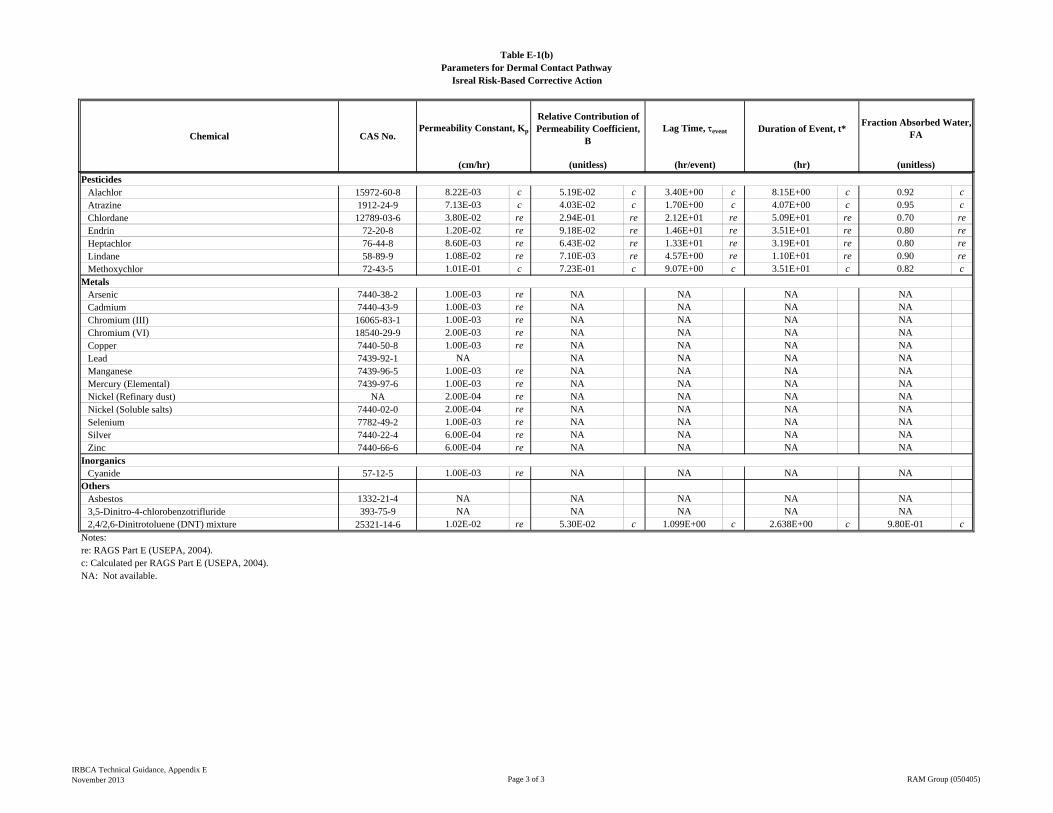
Fraction Absorbed Water, FA
(cm/hr) (unitless) (hr/event) (hr) (unitless)
Permeability Constant, Kp
Relative Contribution of Permeability Coefficient,
BLag Time,event Duration of Event, t*
Table E-1(b)Parameters for Dermal Contact Pathway
Isreal Risk-Based Corrective Action
Chemical CAS No.
PesticidesAlachlor 15972-60-8 8.22E-03 c 5.19E-02 c 3.40E+00 c 8.15E+00 c 0.92 cAtrazine 1912-24-9 7.13E-03 c 4.03E-02 c 1.70E+00 c 4.07E+00 c 0.95 cChlordane 12789-03-6 3.80E-02 re 2.94E-01 re 2.12E+01 re 5.09E+01 re 0.70 reEndrin 72-20-8 1.20E-02 re 9.18E-02 re 1.46E+01 re 3.51E+01 re 0.80 reHeptachlor 76-44-8 8.60E-03 re 6.43E-02 re 1.33E+01 re 3.19E+01 re 0.80 reLindane 58-89-9 1.08E-02 re 7.10E-03 re 4.57E+00 re 1.10E+01 re 0.90 reMethoxychlor 72-43-5 1.01E-01 c 7.23E-01 c 9.07E+00 c 3.51E+01 c 0.82 c
MetalsArsenic 7440-38-2 1.00E-03 re NA NA NA NACadmium 7440-43-9 1.00E-03 re NA NA NA NAChromium (III) 16065-83-1 1.00E-03 re NA NA NA NAChromium (VI) 18540-29-9 2.00E-03 re NA NA NA NACopper 7440-50-8 1.00E-03 re NA NA NA NALead 7439-92-1 NA NA NA NA NAManganese 7439-96-5 1.00E-03 re NA NA NA NAMercury (Elemental) 7439-97-6 1.00E-03 re NA NA NA NANickel (Refinary dust) NA 2.00E-04 re NA NA NA NANickel (Soluble salts) 7440-02-0 2.00E-04 re NA NA NA NASelenium 7782-49-2 1.00E-03 re NA NA NA NASilver 7440-22-4 6.00E-04 re NA NA NA NAZinc 7440-66-6 6.00E-04 re NA NA NA NA
InorganicsCyanide 57-12-5 1.00E-03 re NA NA NA NA
OthersAsbestos 1332-21-4 NA NA NA NA NA3,5-Dinitro-4-chlorobenzotrifluride 393-75-9 NA NA NA NA NA2,4/2,6-Dinitrotoluene (DNT) mixture 25321-14-6 1.02E-02 re 5.30E-02 c 1.099E+00 c 2.638E+00 c 9.80E-01 c
Notes:re: RAGS Part E (USEPA, 2004).c: Calculated per RAGS Part E (USEPA, 2004).NA: Not available.
IRBCA Technical Guidance, Appendix ENovember 2013 Page 3 of 3 RAM Group (050405)
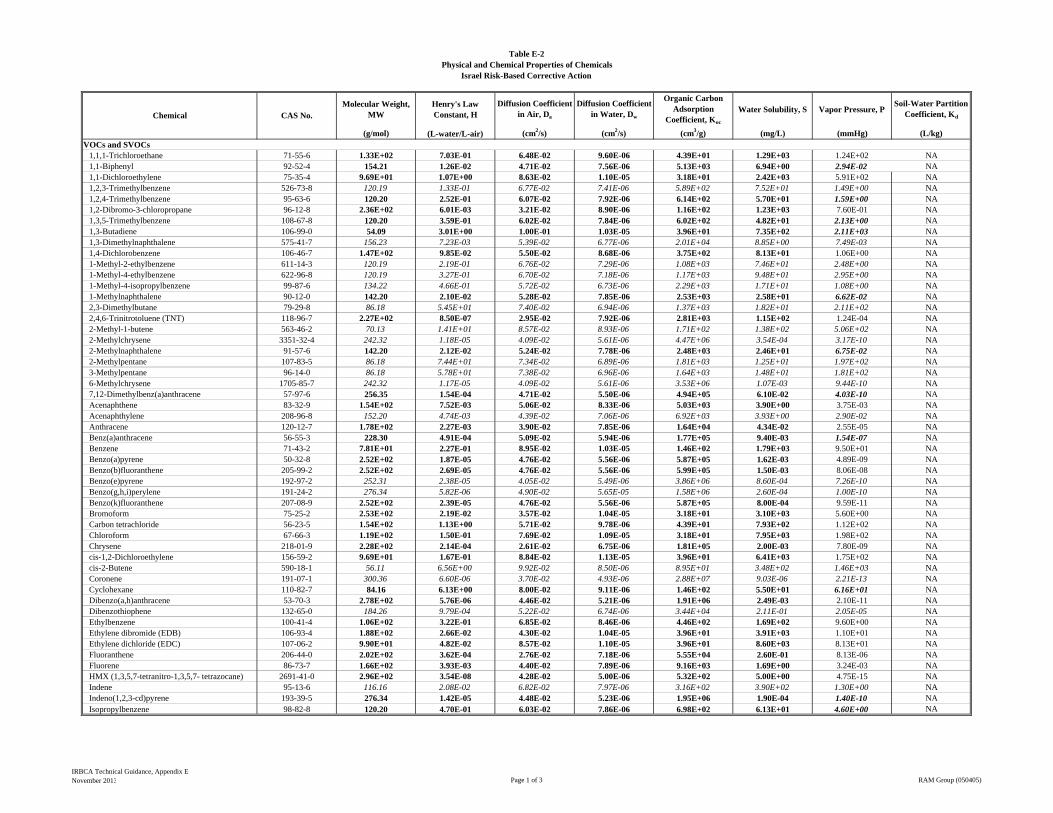
Molecular Weight, MW
Henry's Law Constant, H
Diffusion Coefficient in Air, Da
Diffusion Coefficient in Water, Dw
Organic Carbon Adsorption
Coefficient, Koc
Water Solubility, S Vapor Pressure, PSoil-Water Partition
Coefficient, Kd
(g/mol) (L-water/L-air) (cm2/s) (cm2/s) (cm3/g) (mg/L) (mmHg) (L/kg)VOCs and SVOCs
1,1,1-Trichloroethane 71-55-6 1.33E+02 7.03E-01 6.48E-02 9.60E-06 4.39E+01 1.29E+03 1.24E+02 NA1,1-Biphenyl 92-52-4 154.21 1.26E-02 4.71E-02 7.56E-06 5.13E+03 6.94E+00 2.94E-02 NA1,1-Dichloroethylene 75-35-4 9.69E+01 1.07E+00 8.63E-02 1.10E-05 3.18E+01 2.42E+03 5.91E+02 NA1,2,3-Trimethylbenzene 526-73-8 120.19 1.33E-01 6.77E-02 7.41E-06 5.89E+02 7.52E+01 1.49E+00 NA1,2,4-Trimethylbenzene 95-63-6 120.20 2.52E-01 6.07E-02 7.92E-06 6.14E+02 5.70E+01 1.59E+00 NA1,2-Dibromo-3-chloropropane 96-12-8 2.36E+02 6.01E-03 3.21E-02 8.90E-06 1.16E+02 1.23E+03 7.60E-01 NA1,3,5-Trimethylbenzene 108-67-8 120.20 3.59E-01 6.02E-02 7.84E-06 6.02E+02 4.82E+01 2.13E+00 NA1,3-Butadiene 106-99-0 54.09 3.01E+00 1.00E-01 1.03E-05 3.96E+01 7.35E+02 2.11E+03 NA1,3-Dimethylnaphthalene 575-41-7 156.23 7.23E-03 5.39E-02 6.77E-06 2.01E+04 8.85E+00 7.49E-03 NA1,4-Dichlorobenzene 106-46-7 1.47E+02 9.85E-02 5.50E-02 8.68E-06 3.75E+02 8.13E+01 1.06E+00 NA1-Methyl-2-ethylbenzene 611-14-3 120.19 2.19E-01 6.76E-02 7.29E-06 1.08E+03 7.46E+01 2.48E+00 NA1-Methyl-4-ethylbenzene 622-96-8 120.19 3.27E-01 6.70E-02 7.18E-06 1.17E+03 9.48E+01 2.95E+00 NA1-Methyl-4-isopropylbenzene 99-87-6 134.22 4.66E-01 5.72E-02 6.73E-06 2.29E+03 1.71E+01 1.08E+00 NA1-Methylnaphthalene 90-12-0 142.20 2.10E-02 5.28E-02 7.85E-06 2.53E+03 2.58E+01 6.62E-02 NA2,3-Dimethylbutane 79-29-8 86.18 5.45E+01 7.40E-02 6.94E-06 1.37E+03 1.82E+01 2.11E+02 NA2,4,6-Trinitrotoluene (TNT) 118-96-7 2.27E+02 8.50E-07 2.95E-02 7.92E-06 2.81E+03 1.15E+02 1.24E-04 NA2-Methyl-1-butene 563-46-2 70.13 1.41E+01 8.57E-02 8.93E-06 1.71E+02 1.38E+02 5.06E+02 NA2-Methylchrysene 3351-32-4 242.32 1.18E-05 4.09E-02 5.61E-06 4.47E+06 3.54E-04 3.17E-10 NA2-Methylnaphthalene 91-57-6 142.20 2.12E-02 5.24E-02 7.78E-06 2.48E+03 2.46E+01 6.75E-02 NA2-Methylpentane 107-83-5 86.18 7.44E+01 7.34E-02 6.89E-06 1.81E+03 1.25E+01 1.97E+02 NA3-Methylpentane 96-14-0 86.18 5.78E+01 7.38E-02 6.96E-06 1.64E+03 1.48E+01 1.81E+02 NA6-Methylchrysene 1705-85-7 242.32 1.17E-05 4.09E-02 5.61E-06 3.53E+06 1.07E-03 9.44E-10 NA7,12-Dimethylbenz(a)anthracene 57-97-6 256.35 1.54E-04 4.71E-02 5.50E-06 4.94E+05 6.10E-02 4.03E-10 NAAcenaphthene 83-32-9 1.54E+02 7.52E-03 5.06E-02 8.33E-06 5.03E+03 3.90E+00 3.75E-03 NAAcenaphthylene 208-96-8 152.20 4.74E-03 4.39E-02 7.06E-06 6.92E+03 3.93E+00 2.90E-02 NAAnthracene 120-12-7 1.78E+02 2.27E-03 3.90E-02 7.85E-06 1.64E+04 4.34E-02 2.55E-05 NABenz(a)anthracene 56-55-3 228.30 4.91E-04 5.09E-02 5.94E-06 1.77E+05 9.40E-03 1.54E-07 NABenzene 71-43-2 7.81E+01 2.27E-01 8.95E-02 1.03E-05 1.46E+02 1.79E+03 9.50E+01 NABenzo(a)pyrene 50-32-8 2.52E+02 1.87E-05 4.76E-02 5.56E-06 5.87E+05 1.62E-03 4.89E-09 NABenzo(b)fluoranthene 205-99-2 2.52E+02 2.69E-05 4.76E-02 5.56E-06 5.99E+05 1.50E-03 8.06E-08 NABenzo(e)pyrene 192-97-2 252.31 2.38E-05 4.05E-02 5.49E-06 3.86E+06 8.60E-04 7.26E-10 NABenzo(g,h,i)perylene 191-24-2 276.34 5.82E-06 4.90E-02 5.65E-05 1.58E+06 2.60E-04 1.00E-10 NABenzo(k)fluoranthene 207-08-9 2.52E+02 2.39E-05 4.76E-02 5.56E-06 5.87E+05 8.00E-04 9.59E-11 NABromoform 75-25-2 2.53E+02 2.19E-02 3.57E-02 1.04E-05 3.18E+01 3.10E+03 5.60E+00 NACarbon tetrachloride 56-23-5 1.54E+02 1.13E+00 5.71E-02 9.78E-06 4.39E+01 7.93E+02 1.12E+02 NAChloroform 67-66-3 1.19E+02 1.50E-01 7.69E-02 1.09E-05 3.18E+01 7.95E+03 1.98E+02 NAChrysene 218-01-9 2.28E+02 2.14E-04 2.61E-02 6.75E-06 1.81E+05 2.00E-03 7.80E-09 NAcis-1,2-Dichloroethylene 156-59-2 9.69E+01 1.67E-01 8.84E-02 1.13E-05 3.96E+01 6.41E+03 1.75E+02 NAcis-2-Butene 590-18-1 56.11 6.56E+00 9.92E-02 8.50E-06 8.95E+01 3.48E+02 1.46E+03 NACoronene 191-07-1 300.36 6.60E-06 3.70E-02 4.93E-06 2.88E+07 9.03E-06 2.21E-13 NACyclohexane 110-82-7 84.16 6.13E+00 8.00E-02 9.11E-06 1.46E+02 5.50E+01 6.16E+01 NADibenzo(a,h)anthracene 53-70-3 2.78E+02 5.76E-06 4.46E-02 5.21E-06 1.91E+06 2.49E-03 2.10E-11 NADibenzothiophene 132-65-0 184.26 9.79E-04 5.22E-02 6.74E-06 3.44E+04 2.11E-01 2.05E-05 NAEthylbenzene 100-41-4 1.06E+02 3.22E-01 6.85E-02 8.46E-06 4.46E+02 1.69E+02 9.60E+00 NAEthylene dibromide (EDB) 106-93-4 1.88E+02 2.66E-02 4.30E-02 1.04E-05 3.96E+01 3.91E+03 1.10E+01 NAEthylene dichloride (EDC) 107-06-2 9.90E+01 4.82E-02 8.57E-02 1.10E-05 3.96E+01 8.60E+03 8.13E+01 NAFluoranthene 206-44-0 2.02E+02 3.62E-04 2.76E-02 7.18E-06 5.55E+04 2.60E-01 8.13E-06 NAFluorene 86-73-7 1.66E+02 3.93E-03 4.40E-02 7.89E-06 9.16E+03 1.69E+00 3.24E-03 NAHMX (1,3,5,7-tetranitro-1,3,5,7- tetrazocane) 2691-41-0 2.96E+02 3.54E-08 4.28E-02 5.00E-06 5.32E+02 5.00E+00 4.75E-15 NAIndene 95-13-6 116.16 2.08E-02 6.82E-02 7.97E-06 3.16E+02 3.90E+02 1.30E+00 NAIndeno(1,2,3-cd)pyrene 193-39-5 276.34 1.42E-05 4.48E-02 5.23E-06 1.95E+06 1.90E-04 1.40E-10 NAIsopropylbenzene 98-82-8 120.20 4.70E-01 6.03E-02 7.86E-06 6.98E+02 6.13E+01 4.60E+00 NA
Table E-2Physical and Chemical Properties of Chemicals
Israel Risk-Based Corrective Action
Chemical CAS No.
IRBCA Technical Guidance, Appendix ENovember 2013 Page 1 of 3 RAM Group (050405)
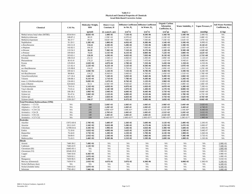
Molecular Weight, MW
Henry's Law Constant, H
Diffusion Coefficient in Air, Da
Diffusion Coefficient in Water, Dw
Organic Carbon Adsorption
Coefficient, Koc
Water Solubility, S Vapor Pressure, PSoil-Water Partition
Coefficient, Kd
(g/mol) (L-water/L-air) (cm2/s) (cm2/s) (cm3/g) (mg/L) (mmHg) (L/kg)
Table E-2Physical and Chemical Properties of Chemicals
Israel Risk-Based Corrective Action
Chemical CAS No.
Methyl teriary butyl ether (MTBE) 1634-04-4 8.82E+01 2.40E-02 7.53E-02 8.59E-06 1.16E+01 5.10E+04 2.49E+02 NAMethylcyclohexane 108-87-2 98.19 1.59E+01 6.97E-02 7.59E-06 2.13E+03 1.04E+01 3.08E+01 NAMethylcyclopentane 96-37-7 84.16 9.82E+00 7.84E-02 7.59E-06 7.33E+02 5.02E+01 1.07E+02 NANaphthalene 91-20-3 1.28E+02 1.80E-02 6.05E-02 8.38E-06 1.54E+03 3.10E+01 8.89E-02 NAn-Butylbenzene 104-51-8 134.22 6.50E-01 5.28E-02 7.33E-06 1.48E+03 1.18E+01 8.14E-01 NAn-Heptane 142-82-5 100.20 8.37E+01 6.54E-02 7.00E-06 6.90E+03 2.66E+00 4.07E+01 NAn-Hexane 110-54-3 86.18 7.36E+01 7.31E-02 8.17E-06 1.32E+02 9.50E+00 1.52E+02 NAn-Pentane 109-66-0 72.15 5.11E+01 8.21E-02 8.80E-06 7.22E+01 3.80E+01 4.62E+02 NAn-Propylbenzene 103-65-1 120.20 4.29E-01 6.02E-02 7.83E-06 8.13E+02 5.22E+01 2.71E+00 NAPerylene 198-55-0 252.31 3.50E-13 4.06E-02 5.49E-06 3.89E+06 1.31E-04 1.11E-10 NAPhenanthrene 85-01-8 178.23 5.40E-03 3.33E-02 7.47E-06 1.41E+04 9.94E-01 6.80E-04 NAPyrene 129-00-0 2.02E+02 4.87E-04 2.78E-02 7.25E-06 5.43E+04 1.35E-01 4.25E-06 NARDX 121-82-4 2.22E+02 8.22E-10 3.12E-02 8.50E-06 8.91E+01 5.97E+01 1.00E-09 NAsec-Butylbenzene 135-98-8 134.22 5.07E-01 5.75E-02 6.75E-06 2.09E+03 1.81E+01 1.25E+00 NAStyrene 100-42-5 1.04E+02 1.12E-01 7.11E-02 8.78E-06 4.46E+02 3.10E+02 6.24E+00 NAtert-Butylbenzene 98-06-6 134.22 8.56E-01 5.84E-02 6.76E-06 2.45E+03 1.51E+01 1.76E+00 NATetrachloroethylene 127-18-4 1.66E+02 7.24E-01 5.05E-02 9.46E-06 9.49E+01 2.06E+02 1.84E+01 NAToluene 108-88-3 9.21E+01 2.71E-01 7.78E-02 9.20E-06 2.34E+02 5.26E+02 2.82E+01 NAtrans-1,2-Dichloroethylene 156-60-5 9.69E+01 1.67E-01 8.76E-02 1.12E-05 3.96E+01 4.52E+03 3.52E+02 NAtrans-2-Butene 624-64-6 56.11 6.56E+00 9.92E-02 8.50E-06 8.95E+01 3.48E+02 1.46E+03 NATrichloroethylene 79-01-6 1.31E+02 4.03E-01 6.87E-02 1.02E-05 6.07E+01 1.28E+03 7.20E+01 NAVinyl chloride 75-01-4 6.25E+01 1.14E+00 1.07E-01 1.20E-05 2.17E+01 8.80E+03 2.80E+03 NAXylene (m) 108-38-3 1.06E+02 2.94E-01 6.84E-02 8.44E-06 3.75E+02 1.61E+02 8.00E+00 NAXylene (o) 95-47-6 1.06E+02 2.12E-01 6.89E-02 8.53E-06 3.83E+02 1.78E+02 6.75E+00 NAXylene (p) 106-42-3 106.17 2.82E-01 6.82E-02 8.42E-06 3.75E+02 1.62E+02 8.76E+00 NAXylenes (total) 1330-20-7 106.17 2.12E-01 8.47E-02 9.90E-06 3.83E+02 1.06E+02 8.06E+00 NA
Total Petroleum Hydrocarbons (TPH)Aliphatics - > C5-C8 NA 100 5.00E+01 1.00E-01 1.00E-05 3.98E+03 5.40E+00 5.02E+01 NAAliphatics - > C9-C18 NA 160 1.20E+02 1.00E-01 1.00E-05 2.51E+05 3.40E-02 4.74E-01 NAAliphatics - >C19-C32 NA 270 4.90E+03* 1.00E-01* 1.00E-05* 6.31E+08* 2.50E-06* 8.44E-04 NAAromatics - >C6-C8 NA 100 2.70E-01 1.00E-01 1.00E-05 2.51E+02 5.20E+02 2.61E+01 NAAromatics - >C9-C16 NA 140 1.40E-01 1.00E-01 1.00E-05 2.51E+03 2.50E+01 4.65E-01 NAAromatics - >C17-C32 NA 220 6.84E-03** 1.00E-01** 1.00E-05** 7.09E+03** 3.28E-01** 1.90E-04 NA
PesticidesAlachlor 15972-60-8 2.70E+02 3.40E-07 2.26E-02 5.69E-06 3.12E+02 2.40E+02 2.20E-05 NAAtrazine 1912-24-9 2.16E+02 9.65E-08 5.28E-02 6.17E-06 2.25E+02 3.47E+01 3.00E-07 NAChlordane 12789-03-6 4.10E+02 1.99E-03 3.44E-02 4.02E-06 3.38E+04 5.60E-02 1.00E-05 NAEndrin 72-20-8 3.81E+02 4.09E-04 3.62E-02 4.22E-06 2.01E+04 2.50E-01 5.84E-07 NAHeptachlor 76-44-8 3.73E+02 1.20E-02 2.23E-02 5.70E-06 4.13E+04 1.80E-01 3.26E-04 NALindane 58-89-9 2.91E+02 2.10E-04 4.33E-02 5.06E-06 2.81E+03 7.30E+00 3.72E-05 NAMethoxychlor 72-43-5 3.46E+02 8.30E-06 2.21E-02 5.59E-06 2.69E+04 1.00E-01 1.23E-06 NA
MetalsArsenic 7440-38-2 7.49E+01 NA NA NA NA NA NA 2.90E+01Cadmium 7440-43-9 1.12E+02 NA NA NA NA NA NA 7.50E+01Chromium (III) 16065-83-1 NA NA NA NA NA NA NA 1.80E+06Chromium (VI) 18540-29-9 NA NA NA NA NA NA NA 1.90E+01Copper 7440-50-8 6.36E+01 NA NA NA NA NA NA 3.98E+01Lead 7439-92-1 2.07E+02 NA NA NA NA NA NA 1.00E+01Manganese 7439-96-5 5.49E+01 NA NA NA NA NA NA 5.01E+01Mercury (Elemental) 7439-97-6 2.01E+02 4.67E-01 3.07E-02 6.30E-06 NA 6.00E-02 1.30E-03 5.20E+01Nickel (Refinary dust) NA NA NA NA NA NA NA NA 6.50E+01Nickel (Soluble Salts) 7440-02-0 5.87E+01 NA NA NA NA NA NA 6.50E+01Selenium 7782-49-2 7.90E+01 NA NA NA NA NA NA 5.00E+00
IRBCA Technical Guidance, Appendix ENovember 2013 Page 2 of 3 RAM Group (050405)
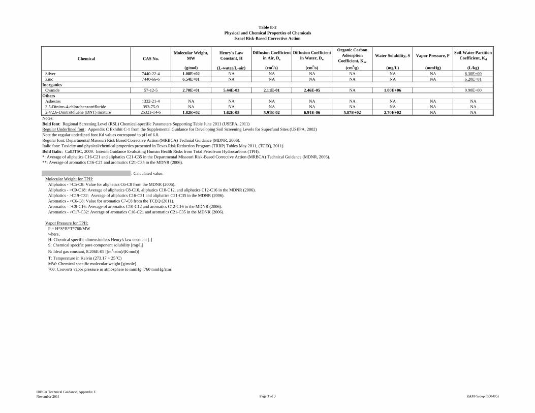
Molecular Weight, MW
Henry's Law Constant, H
Diffusion Coefficient in Air, Da
Diffusion Coefficient in Water, Dw
Organic Carbon Adsorption
Coefficient, Koc
Water Solubility, S Vapor Pressure, PSoil-Water Partition
Coefficient, Kd
(g/mol) (L-water/L-air) (cm2/s) (cm2/s) (cm3/g) (mg/L) (mmHg) (L/kg)
Table E-2Physical and Chemical Properties of Chemicals
Israel Risk-Based Corrective Action
Chemical CAS No.
Silver 7440-22-4 1.08E+02 NA NA NA NA NA NA 8.30E+00Zinc 7440-66-6 6.54E+01 NA NA NA NA NA NA 6.20E+01
InorganicsCyanide 57-12-5 2.70E+01 5.44E-03 2.11E-01 2.46E-05 NA 1.00E+06 9.90E+00
OthersAsbestos 1332-21-4 NA NA NA NA NA NA NA NA3,5-Dinitro-4-chlorobenzotrifluride 393-75-9 NA NA NA NA NA NA NA NA2,4/2,6-Dinitrotoluene (DNT) mixture 25321-14-6 1.82E+02 1.62E-05 5.91E-02 6.91E-06 5.87E+02 2.70E+02 NA NA
Notes:Bold font: Regional Screening Level (RSL) Chemical-specific Parameters Supporting Table June 2011 (USEPA, 2011)Regular Underlined font: Appendix C Exhibit C-1 from the Supplemental Guidance for Developing Soil Screening Levels for Superfund Sites (USEPA, 2002) Note the regular underlined font Kd values correspond to pH of 6.8.Regular font: Departmental Missouri Risk Based Corrective Action (MRBCA) Technial Guidance (MDNR, 2006).Italic font: Toxicity and physical/chemical properties presented in Texas Risk Reduction Program (TRRP) Tables May 2011, (TCEQ, 2011).Bold Italic: CalDTSC, 2009. Interim Guidance Evaluating Human Health Risks from Total Petroleum Hydrocarbons (TPH).
: Calculated value.Molecular Weight for TPH:
Aliphatics - >C5-C8: Value for aliphatics C6-C8 from the MDNR (2006).Aliphatics - >C9-C18: Average of aliphatics C8-C10, aliphatics C10-C12, and aliphatics C12-C16 in the MDNR (2006).Aliphatics - >C19-C32: Average of aliphatics C16-C21 and aliphatics C21-C35 in the MDNR (2006).Aromatics - >C6-C8: Value for aromatics C7-C8 from the TCEQ (2011).Aromatics - >C9-C16: Average of aromatics C10-C12 and aromatics C12-C16 in the MDNR (2006).Aromatics - >C17-C32: Average of aromatics C16-C21 and aromatics C21-C35 in the MDNR (2006).
Vapor Pressure for TPH:P = H*S*R*T*760/MWwhere,H: Chemical specific dimensionless Henry's law constant [-]S: Chemical specific pure component solubility [mg/L]
R: Ideal gas constant, 8.206E-05 [(m3-atm)/(K-mol)]
T: Temperature in Kelvin (273.17 + 25 oC)MW: Chemical specific molecular weight [g/mole]760: Converts vapor pressure in atmosphere to mmHg [760 mmHg/atm]
**: Average of aromatics C16-C21 and aromatics C21-C35 in the MDNR (2006).*: Average of aliphatics C16-C21 and aliphatics C21-C35 in the Departmental Missouri Risk-Based Corrective Action (MRBCA) Technical Guidance (MDNR, 2006).
IRBCA Technical Guidance, Appendix ENovember 2013 Page 3 of 3 RAM Group (050405)

Table E-3Exposure Factors
Israel Risk-Based Corrective Action
Parameter Symbol Unit Default
Averaging Time for Carcinogen ATc year 70
Averaging Time for Non-Carcinogen ATnc year =ED
Body Weight:Resident Child BW kg 15Resident Adult BW kg 70Non-Residential Worker BW kg 70Construction Worker BW kg 70
Exposure Duration:Resident Child ED year 6Resident Adult ED year 24Non-Residential Worker ED year 25Construction Worker ED year 1
Exposure Frequency:Resident Child EF day/year 360Resident Adult EF day/year 360Non-Residential Worker EF day/year 250Construction Worker EF day/year 90
Soil Ingestion Rate:Resident Child IRsoil mg/day 200
Resident Adult IRsoil mg/day 100
Non-Residential Worker IRsoil mg/day 100
Construction Worker IRsoil mg/day 330
Groundwater Ingestion Rate:Resident Child IRw L/day 1
Resident Adult IRw L/day 2
Exposure Time for Indoor Inhalation:Resident Child ETin hr/day 18
Resident Adult ETin hr/day 18
Non-Residential Worker ETin hr/day 18
Exposure Time for Outdoor Inhalation:Resident Child ETout hr/day 16
Resident Adult ETout hr/day 16
Non-Residential Worker ETout hr/day 12
Construction Worker ETout hr/day 10
Skin Surface Area for Incidental Dermal Contact with Soil:Resident Child SAsoil cm2/day 2800
Resident Adult SAsoil cm2/day 5700
Non-Residential Worker SAsoil cm2/day 3300
Construction Worker SAsoil cm2/day 3300
IRBCA Technical Guidance, Appendix ENovember 2013 Page 1 of 2 RAM Group (050405)
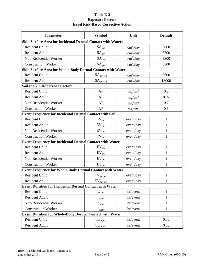
Table E-3Exposure Factors
Israel Risk-Based Corrective Action
Parameter Symbol Unit Default
Skin Surface Area for Incidental Dermal Contact with Water:
Resident Child SAgw cm2/day 2800
Resident Adult SAgw cm2/day 5700
Non-Residential Worker SAgw cm2/day 3300
Construction Worker SAgw cm2/day 3300
Skin Surface Area for Whole-Body Dermal Contact with Water:Resident Child SAgw-wb cm2/day 6600
Resident Adult SAgw-wb cm2/day 18000
Soil to Skin Adherence Factor:Resident Child AF mg/cm2 0.2
Resident Adult AF mg/cm2 0.07
Non-Residential Worker AF mg/cm2 0.2
Construction Worker AF mg/cm2 0.3
Event Frequency for Incidental Dermal Contact with SoilResident Child EVsoil event/day 1
Resident Adult EVsoil event/day 1
Non-Residential Worker EVsoil event/day 1
Construction Worker EVsoil event/day 1
Event Frequency for Incidental Dermal Contact with WaterResident Child EVgw event/day 1
Resident Adult EVgw event/day 1
Non-Residential Worker EVgw event/day 1
Construction Worker EVgw event/day 1
Event Frequency for Whole-Body Dermal Contact with WaterResident Child EVgw_wb event/day 1
Resident Adult EVgw_wb event/day 1
Event Duration for Incidental Dermal Contact with WaterResident Child tevent hr/event 1
Resident Adult tevent hr/event 1
Non-Residential Worker tevent hr/event 1
Construction Worker tevent hr/event 1
Event Duration for Whole-Body Dermal Contact with WaterResident Child tevent_wb hr/event 0.33
Resident Adult tevent_wb hr/event 0.25
IRBCA Technical Guidance, Appendix ENovember 2013 Page 2 of 2 RAM Group (050405)
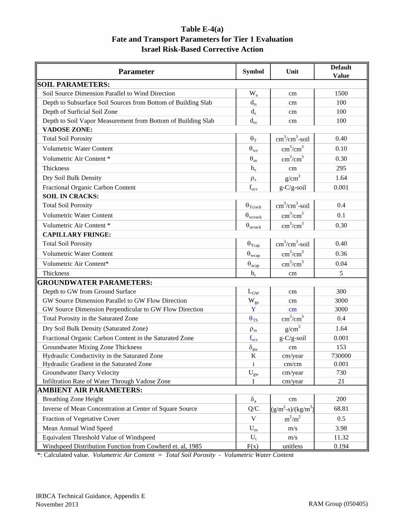
Parameter Symbol UnitDefault Value
SOIL PARAMETERS:Soil Source Dimension Parallel to Wind Direction Wa cm 1500
Depth to Subsurface Soil Sources from Bottom of Building Slab dts cm 100
Depth of Surficial Soil Zone ds cm 100
Depth to Soil Vapor Measurement from Bottom of Building Slab dsv cm 100VADOSE ZONE:Total Soil Porosity T cm3/cm3-soil 0.40
Volumetric Water Content ws cm3/cm3 0.10
Volumetric Air Content * as cm3/cm3 0.30
Thickness hv cm 295
Dry Soil Bulk Density s g/cm3 1.64
Fractional Organic Carbon Content focv g-C/g-soil 0.001SOIL IN CRACKS:Total Soil Porosity Tcrack cm3/cm3-soil 0.4
Volumetric Water Content wcrack cm3/cm3 0.1
Volumetric Air Content * acrack cm3/cm3 0.30
CAPILLARY FRINGE:Total Soil Porosity Tcap cm3/cm3-soil 0.40
Volumetric Water Content wcap cm3/cm3 0.36
Volumetric Air Content* acap cm3/cm3 0.04
Thickness hc cm 5
GROUNDWATER PARAMETERS:Depth to GW from Ground Surface LGW cm 300
GW Source Dimension Parallel to GW Flow Direction Wga cm 3000GW Source Dimension Perpendicular to GW Flow Direction Y cm 3000
Total Porosity in the Saturated Zone TS cm3/cm3 0.4
Dry Soil Bulk Density (Saturated Zone) ss g/cm3 1.64
Fractional Organic Carbon Content in the Saturated Zone focs g-C/g-soil 0.001
Groundwater Mixing Zone Thickness gw cm 153Hydraulic Conductivity in the Saturated Zone K cm/year 730000Hydraulic Gradient in the Saturated Zone i cm/cm 0.001Groundwater Darcy Velocity Ugw cm/year 730Infiltration Rate of Water Through Vadose Zone cm/year 21
AMBIENT AIR PARAMETERS:Breathing Zone Height a cm 200
Inverse of Mean Concentration at Center of Square Source Q/C (g/m2-s)/(kg/m3) 68.81
Fraction of Vegetative Cover V m2/m2 0.5
Mean Annual Wind Speed Um m/s 3.98
Equivalent Threshold Value of Windspeed Ut m/s 11.32Windspeed Distribution Function from Cowherd et. al, 1985 F(x) unitless 0.194
*: Calculated value. Volumetric Air Content = Total Soil Porosity - Volumetric Water Content
Table E-4(a)Fate and Transport Parameters for Tier 1 Evaluation
Israel Risk-Based Corrective Action
IRBCA Technical Guidance, Appendix ENovember 2013 RAM Group (050405)
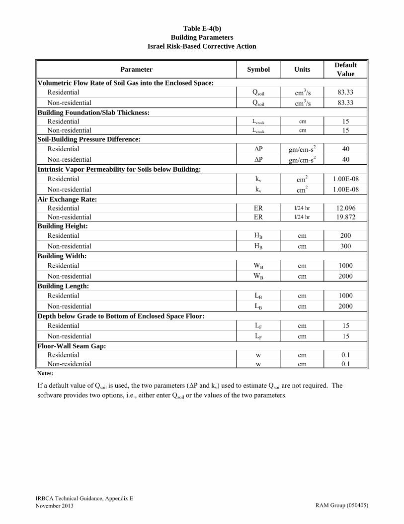
Parameter Symbol UnitsDefault Value
Volumetric Flow Rate of Soil Gas into the Enclosed Space:Residential Qsoil cm3/s 83.33
Non-residential Qsoil cm3/s 83.33
Building Foundation/Slab Thickness:Residential Lcrack cm 15Non-residential Lcrack cm 15
Soil-Building Pressure Difference:Residential ∆P gm/cm-s2 40
Non-residential ∆P gm/cm-s2 40
Intrinsic Vapor Permeability for Soils below Building:Residential kv cm2 1.00E-08
Non-residential kv cm2 1.00E-08
Air Exchange Rate:Residential ER l/24 hr 12.096Non-residential ER l/24 hr 19.872
Building Height:Residential HB cm 200
Non-residential HB cm 300
Building Width:Residential WB cm 1000
Non-residential WB cm 2000
Building Length:Residential LB cm 1000
Non-residential LB cm 2000
Depth below Grade to Bottom of Enclosed Space Floor:Residential LF cm 15
Non-residential LF cm 15
Floor-Wall Seam Gap:Residential w cm 0.1Non-residential w cm 0.1
Notes:
Table E-4(b)Building Parameters
If a default value of Qsoil is used, the two parameters (∆P and kv) used to estimate Qsoil are not required. The software provides two options, i.e., either enter Qsoil or the values of the two parameters.
Israel Risk-Based Corrective Action
IRBCA Technical Guidance, Appendix ENovember 2013 RAM Group (050405)
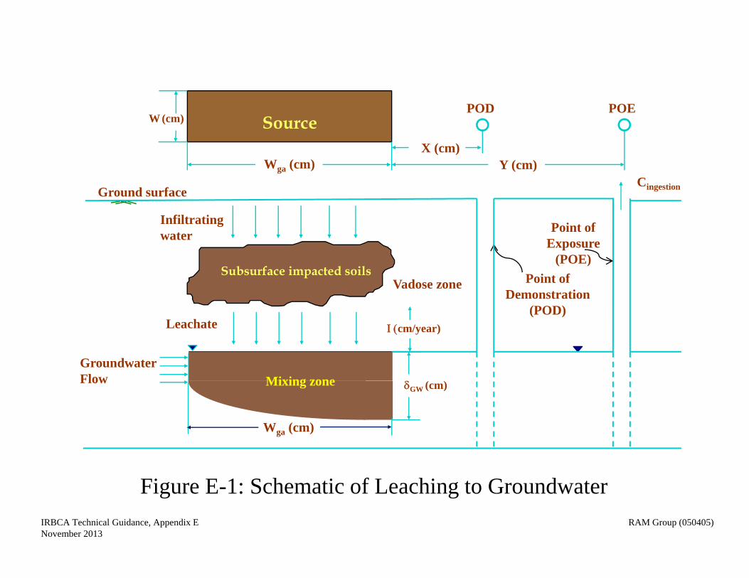
Figure E-1: Schematic of Leaching to Groundwater
Cingestion
Point of Exposure
(POE)
Infiltrating water
Leachate
GroundwaterFlow
Ground surface
Subsurface impacted soilsVadose zone
GW (cm)
cm/year)
Point of Demonstration
(POD)
SourcePOD POE
Wga (cm)
W (cm)
X (cm)Y (cm)
IRBCA Technical Guidance, Appendix E RAM Group (050405)November 2013
Mixing zone
Wga (cm)
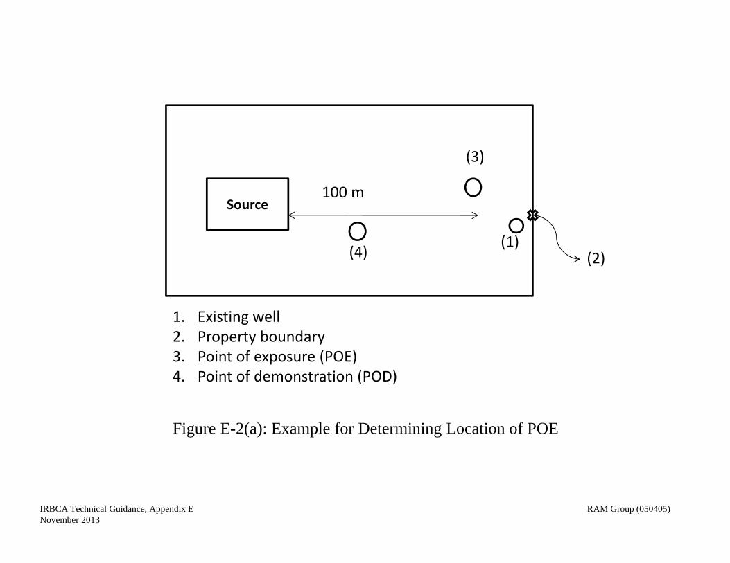
(2)(1)
Source100 m
(3)
(4)
1. Existing well2. Property boundary3. Point of exposure (POE)4. Point of demonstration (POD)
Figure E-2(a): Example for Determining Location of POE
IRBCA Technical Guidance, Appendix E RAM Group (050405)November 2013
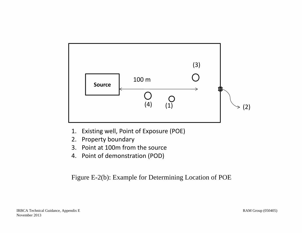
(2)(1)
Source100 m
(3)
(4)
1. Existing well, Point of Exposure (POE)2. Property boundary3. Point at 100m from the source4. Point of demonstration (POD)
Figure E-2(b): Example for Determining Location of POE
IRBCA Technical Guidance, Appendix E RAM Group (050405)November 2013
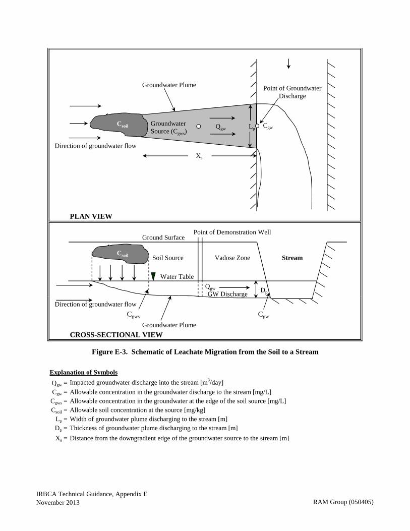
Groundwater Plume
Cgw
Direction of groundwater flow
PLAN VIEW
Ground Surface
Soil Source Vadose Zone Stream
Water Table
GW Discharge
Xs
Csoil Groundwater Source (Cgws)
Qgw Lp
Dp
Csoil
Qgw
Point of Demonstration Well
Point of Groundwater Discharge
GW sc ge
Direction of groundwater flow
Cgws Cgw
Groundwater Plume
CROSS-SECTIONAL VIEW
Explanation of Symbols
Qgw = Impacted groundwater discharge into the stream [m3/day]
Cgw = Allowable concentration in the groundwater discharge to the stream [mg/L]Cgws = Allowable concentration in the groundwater at the edge of the soil source [mg/L]Csoil = Allowable soil concentration at the source [mg/kg]
Lp = Width of groundwater plume discharging to the stream [m]Dp = Thickness of groundwater plume discharging to the stream [m]
Xs = Distance from the downgradient edge of the groundwater source to the stream [m]
Figure E-3. Schematic of Leachate Migration from the Soil to a Stream
IRBCA Technical Guidance, Appendix ENovember 2013 RAM Group (050405)
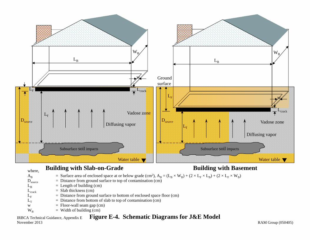
Figure E-4. Schematic Diagrams for J&E Model
Building with BasementBuilding with Slab-on-Gradewhere,AB = Surface area of enclosed space at or below grade (cm2), AB = (LB × WB) + (2 × LF × LB) + (2 × LF × WB)Dsource = Distance from ground surface to top of contamination (cm)LB = Length of building (cm)Lcrack = Slab thickness (cm)LF = Distance from ground surface to bottom of enclosed space floor (cm)LT = Distance from bottom of slab to top of contamination (cm)w = Floor-wall seam gap (cm)WB = Width of building (cm)
Subsurface soil impacts
Vadose zone
Water table
LF
Dsource
Lcrack
Diffusing vapor
LB
WB
LT
w Ground surface
Subsurface soil impacts
Vadose zone
Water table
LF
Dsource
Lcrack
Diffusing vapor
LB
WB
LT
w
IRBCA Technical Guidance, Appendix ENovember 2013 RAM Group (050405)
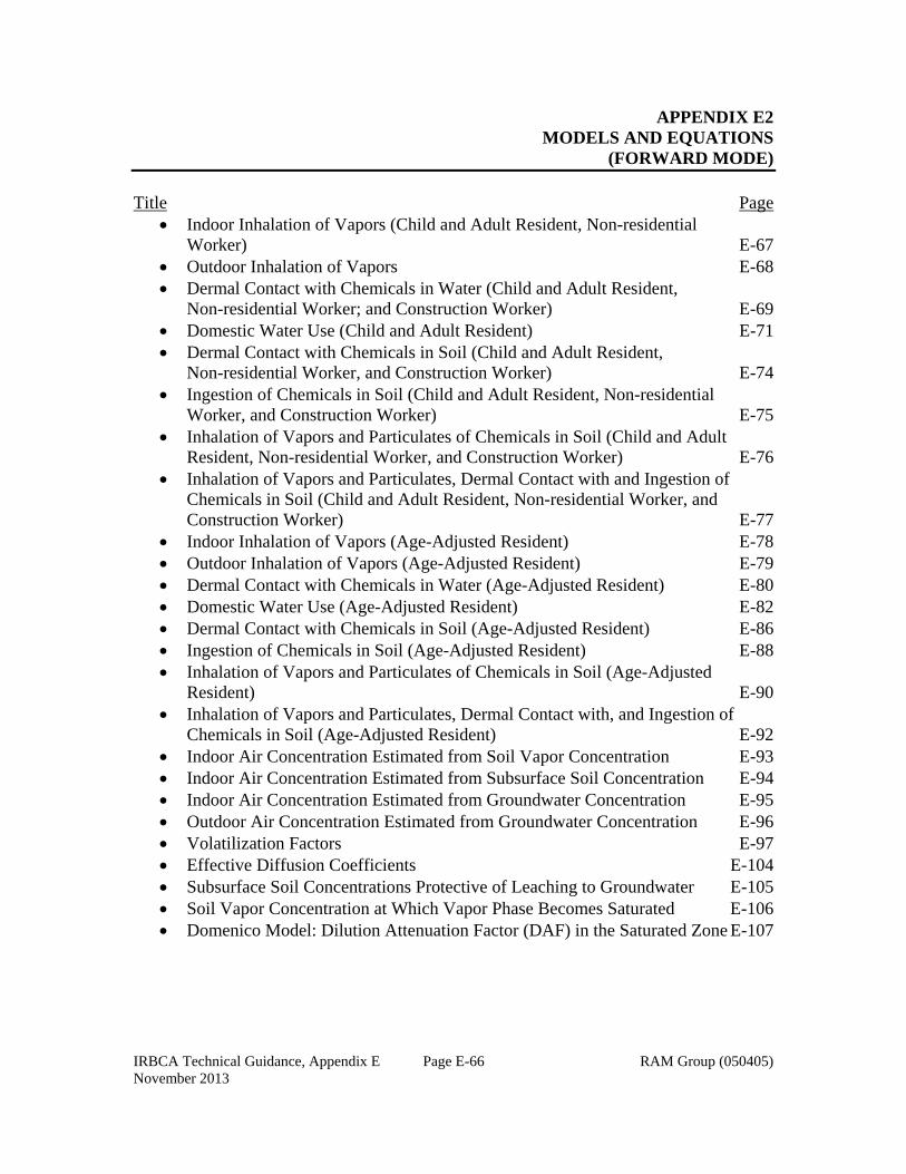
IRBCA Technical Guidance, Appendix E Page E-66 RAM Group (050405) November 2013
APPENDIX E2 MODELS AND EQUATIONS
(FORWARD MODE) Title Page
Indoor Inhalation of Vapors (Child and Adult Resident, Non-residential Worker) E-67 Outdoor Inhalation of Vapors E-68 Dermal Contact with Chemicals in Water (Child and Adult Resident,
Non-residential Worker; and Construction Worker) E-69 Domestic Water Use (Child and Adult Resident) E-71 Dermal Contact with Chemicals in Soil (Child and Adult Resident,
Non-residential Worker, and Construction Worker) E-74 Ingestion of Chemicals in Soil (Child and Adult Resident, Non-residential
Worker, and Construction Worker) E-75 Inhalation of Vapors and Particulates of Chemicals in Soil (Child and Adult Resident, Non-residential Worker, and Construction Worker) E-76 Inhalation of Vapors and Particulates, Dermal Contact with and Ingestion of Chemicals in Soil (Child and Adult Resident, Non-residential Worker, and Construction Worker) E-77 Indoor Inhalation of Vapors (Age-Adjusted Resident) E-78 Outdoor Inhalation of Vapors (Age-Adjusted Resident) E-79 Dermal Contact with Chemicals in Water (Age-Adjusted Resident) E-80 Domestic Water Use (Age-Adjusted Resident) E-82 Dermal Contact with Chemicals in Soil (Age-Adjusted Resident) E-86 Ingestion of Chemicals in Soil (Age-Adjusted Resident) E-88 Inhalation of Vapors and Particulates of Chemicals in Soil (Age-Adjusted
Resident) E-90 Inhalation of Vapors and Particulates, Dermal Contact with, and Ingestion of
Chemicals in Soil (Age-Adjusted Resident) E-92 Indoor Air Concentration Estimated from Soil Vapor Concentration E-93 Indoor Air Concentration Estimated from Subsurface Soil Concentration E-94 Indoor Air Concentration Estimated from Groundwater Concentration E-95 Outdoor Air Concentration Estimated from Groundwater Concentration E-96 Volatilization Factors E-97 Effective Diffusion Coefficients E-104 Subsurface Soil Concentrations Protective of Leaching to Groundwater E-105 Soil Vapor Concentration at Which Vapor Phase Becomes Saturated E-106 Domenico Model: Dilution Attenuation Factor (DAF) in the Saturated Zone E-107
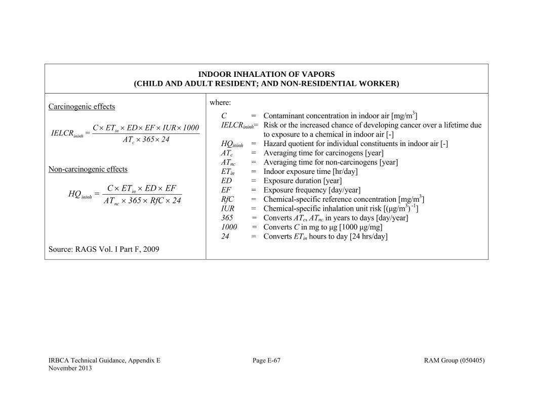
IRBCA Technical Guidance, Appendix E Page E-67 RAM Group (050405) November 2013
INDOOR INHALATION OF VAPORS (CHILD AND ADULT RESIDENT; AND NON-RESIDENTIAL WORKER)
Carcinogenic effects
24365 AT1000IUR EF EDET C
= IELCRc
inininh
Non-carcinogenic effects
24RfC 365 ATEF EDETC = HQ
nc
inininh
Source: RAGS Vol. I Part F, 2009
where:
C = Contaminant concentration in indoor air [mg/m3] IELCRininh= Risk or the increased chance of developing cancer over a lifetime due
to exposure to a chemical in indoor air [-] HQininh = Hazard quotient for individual constituents in indoor air [-] ATc = Averaging time for carcinogens [year] ATnc = Averaging time for non-carcinogens [year] ETin = Indoor exposure time [hr/day] ED = Exposure duration [year] EF = Exposure frequency [day/year] RfC = Chemical-specific reference concentration [mg/m3] IUR = Chemical-specific inhalation unit risk [(μg/m3) -1] 365 = Converts ATc, ATnc in years to days [day/year] 1000 = Converts C in mg to μg [1000 μg/mg] 24 = Converts ETin hours to day [24 hrs/day]
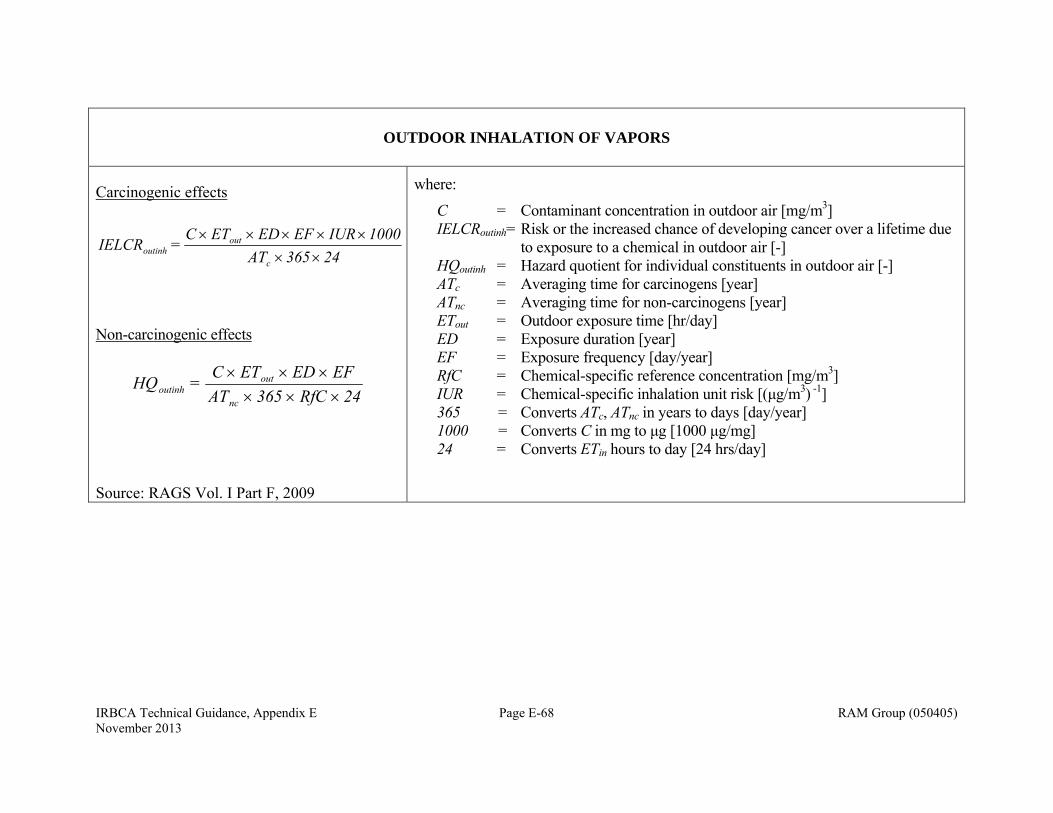
IRBCA Technical Guidance, Appendix E Page E-68 RAM Group (050405) November 2013
OUTDOOR INHALATION OF VAPORS
Carcinogenic effects
24365 AT1000IUR EF EDET C
= IELCRc
outoutinh
Non-carcinogenic effects
24RfC 365 ATEF EDETC = HQ
nc
outoutinh
Source: RAGS Vol. I Part F, 2009
where:
C = Contaminant concentration in outdoor air [mg/m3] IELCRoutinh= Risk or the increased chance of developing cancer over a lifetime due
to exposure to a chemical in outdoor air [-] HQoutinh = Hazard quotient for individual constituents in outdoor air [-] ATc = Averaging time for carcinogens [year] ATnc = Averaging time for non-carcinogens [year] ETout = Outdoor exposure time [hr/day] ED = Exposure duration [year] EF = Exposure frequency [day/year] RfC = Chemical-specific reference concentration [mg/m3] IUR = Chemical-specific inhalation unit risk [(μg/m3) -1] 365 = Converts ATc, ATnc in years to days [day/year] 1000 = Converts C in mg to μg [1000 μg/mg] 24 = Converts ETin hours to day [24 hrs/day]
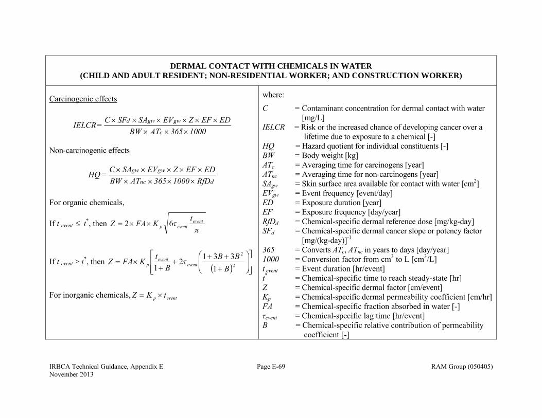
IRBCA Technical Guidance, Appendix E Page E-69 RAM Group (050405) November 2013
DERMAL CONTACT WITH CHEMICALS IN WATER (CHILD AND ADULT RESIDENT; NON-RESIDENTIAL WORKER; AND CONSTRUCTION WORKER)
Carcinogenic effects
1000365 AT BWEDEFZEVSASFC = IELCR
c
gwgwd
Non-carcinogenic effects
dnc
gwgw
RfD1000 365 AT BWEDEF Z EVSAC =HQ
For organic chemicals,
If t event t*, then
eventeventp
tKFAZ 62
If t event > t*, then
2
2
1
3312
1 BBB
Bt
KFAZ eventevent
p
For inorganic chemicals, eventp tKZ
where:
C = Contaminant concentration for dermal contact with water [mg/L]
IELCR = Risk or the increased chance of developing cancer over a lifetime due to exposure to a chemical [-]
HQ = Hazard quotient for individual constituents [-] BW = Body weight [kg] ATc = Averaging time for carcinogens [year] ATnc = Averaging time for non-carcinogens [year] SAgw = Skin surface area available for contact with water [cm2] EVgw = Event frequency [event/day] ED = Exposure duration [year] EF = Exposure frequency [day/year] RfDd = Chemical-specific dermal reference dose [mg/kg-day] SFd = Chemical-specific dermal cancer slope or potency factor
[mg/(kg-day)]-1
365 = Converts ATc, ATnc in years to days [day/year] 1000 = Conversion factor from cm3 to L [cm3/L] t event = Event duration [hr/event] t* = Chemical-specific time to reach steady-state [hr] Z = Chemical-specific dermal factor [cm/event] Kp = Chemical-specific dermal permeability coefficient [cm/hr] FA = Chemical-specific fraction absorbed in water [-] τevent = Chemical-specific lag time [hr/event] B = Chemical-specific relative contribution of permeability
coefficient [-]
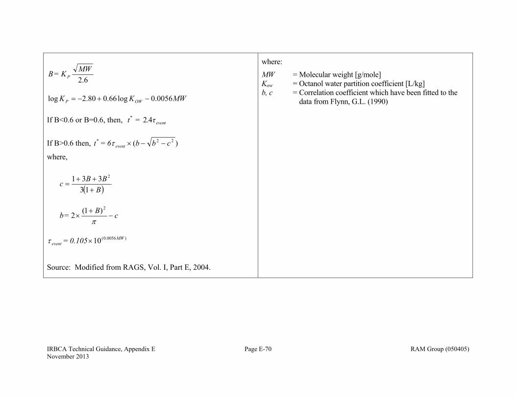
IRBCA Technical Guidance, Appendix E Page E-70 RAM Group (050405) November 2013
6.2
MWK = B P
MWKK OWP 0056.0log66.080.2log
If B<0.6 or B=0.6, then, teven
* τ. = t 42
If B>0.6 then, )( 22 cbb6 = t event*
where,
BBBc
13
331 2
cB = b
2)1(2
)0056.0(10 MW
event 0.105 =
Source: Modified from RAGS, Vol. I, Part E, 2004.
where:
MW = Molecular weight [g/mole] Kow = Octanol water partition coefficient [L/kg] b, c = Correlation coefficient which have been fitted to the
data from Flynn, G.L. (1990)
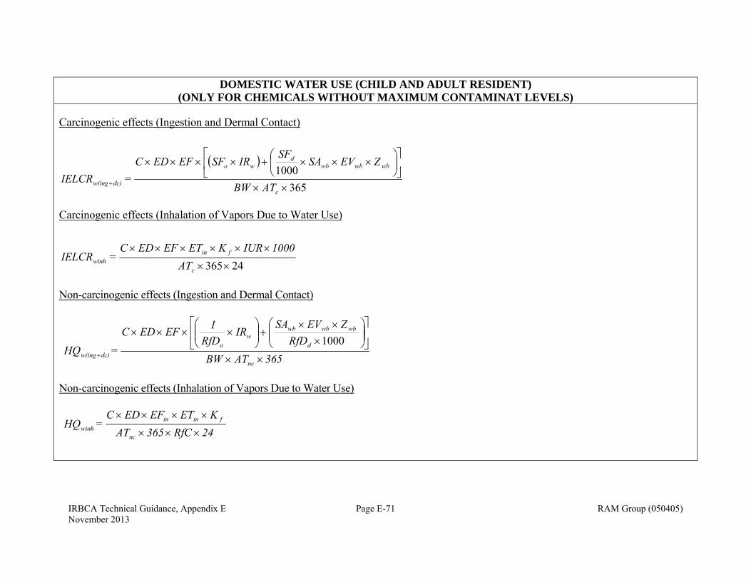
IRBCA Technical Guidance, Appendix E Page E-71 RAM Group (050405) November 2013
DOMESTIC WATER USE (CHILD AND ADULT RESIDENT) (ONLY FOR CHEMICALS WITHOUT MAXIMUM CONTAMINAT LEVELS)
Carcinogenic effects (Ingestion and Dermal Contact)
365
1000
c
wbwbwbd
wo
dc)w(ing ATWB
ZEVSASF
IRSFEFEDC =IELCR
Carcinogenic effects (Inhalation of Vapors Due to Water Use)
24365
c
finwinh TA
1000IURKETEFEDC =IELCR
Non-carcinogenic effects (Ingestion and Dermal Contact)
365ATWBRfD
ZEVSAIR
RfD1EFEDC
=HQ nc
d
wbwbwbw
odc)w(ing
1000
Non-carcinogenic effects (Inhalation of Vapors Due to Water Use)
24RfC365TAKETEFEDC
=HQ nc
fininwinh
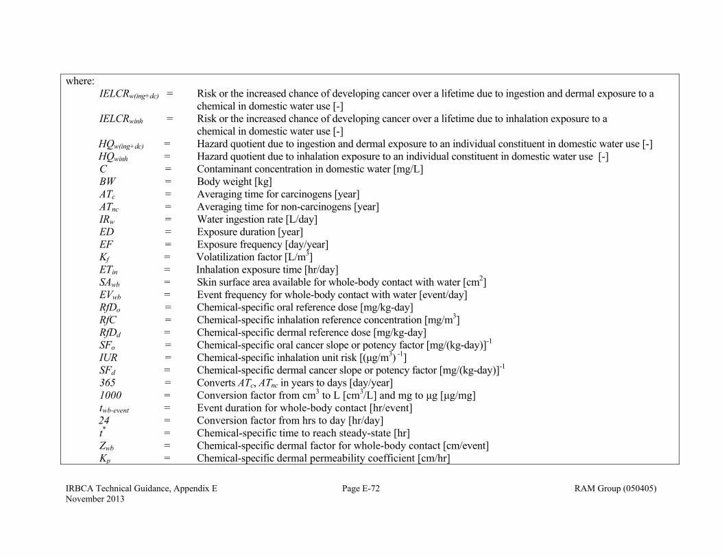
IRBCA Technical Guidance, Appendix E Page E-72 RAM Group (050405) November 2013
where: IELCRw(ing+dc) = Risk or the increased chance of developing cancer over a lifetime due to ingestion and dermal exposure to a
chemical in domestic water use [-] IELCRwinh = Risk or the increased chance of developing cancer over a lifetime due to inhalation exposure to a
chemical in domestic water use [-] HQw(ing+dc) = Hazard quotient due to ingestion and dermal exposure to an individual constituent in domestic water use [-] HQwinh = Hazard quotient due to inhalation exposure to an individual constituent in domestic water use [-] C = Contaminant concentration in domestic water [mg/L] BW = Body weight [kg] ATc = Averaging time for carcinogens [year] ATnc = Averaging time for non-carcinogens [year] IRw = Water ingestion rate [L/day] ED = Exposure duration [year] EF = Exposure frequency [day/year] Kf = Volatilization factor [L/m3] ETin = Inhalation exposure time [hr/day] SAwb = Skin surface area available for whole-body contact with water [cm2] EVwb = Event frequency for whole-body contact with water [event/day] RfDo = Chemical-specific oral reference dose [mg/kg-day] RfC = Chemical-specific inhalation reference concentration [mg/m3] RfDd = Chemical-specific dermal reference dose [mg/kg-day] SFo = Chemical-specific oral cancer slope or potency factor [mg/(kg-day)]-1 IUR = Chemical-specific inhalation unit risk [(μg/m3) -1] SFd = Chemical-specific dermal cancer slope or potency factor [mg/(kg-day)]-1
365 = Converts ATc, ATnc in years to days [day/year] 1000 = Conversion factor from cm3 to L [cm3/L] and mg to μg [μg/mg] twb-event = Event duration for whole-body contact [hr/event] 24 = Conversion factor from hrs to day [hr/day] t* = Chemical-specific time to reach steady-state [hr] Zwb = Chemical-specific dermal factor for whole-body contact [cm/event] Kp = Chemical-specific dermal permeability coefficient [cm/hr]
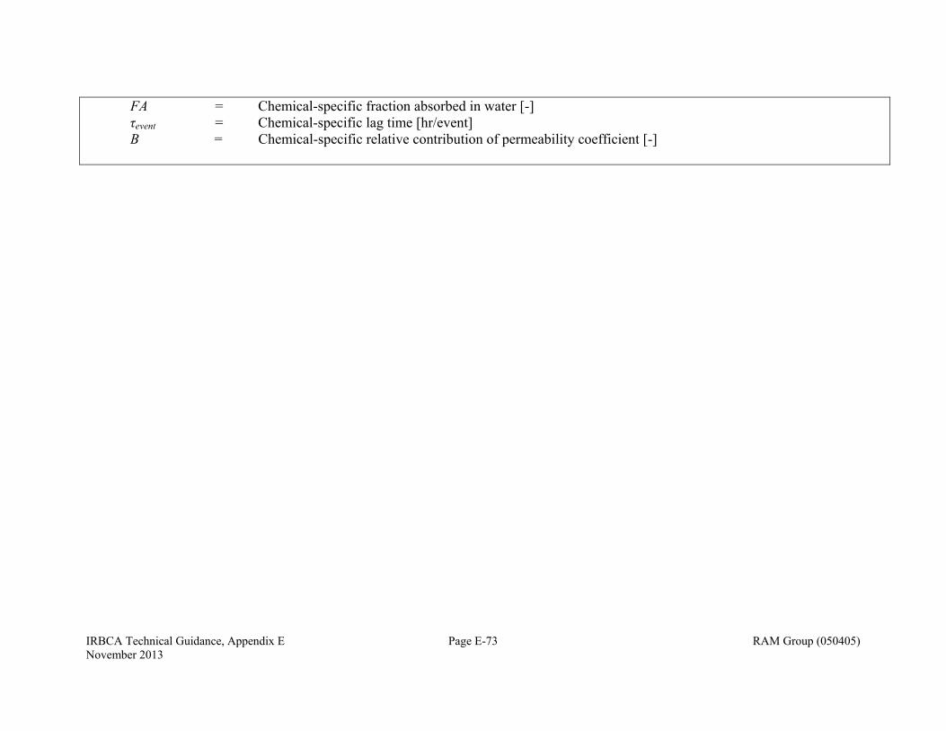
IRBCA Technical Guidance, Appendix E Page E-73 RAM Group (050405) November 2013
FA = Chemical-specific fraction absorbed in water [-] τevent = Chemical-specific lag time [hr/event] B = Chemical-specific relative contribution of permeability coefficient [-]
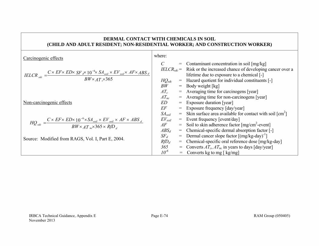
IRBCA Technical Guidance, Appendix E Page E-74 RAM Group (050405) November 2013
DERMAL CONTACT WITH CHEMICALS IN SOIL (CHILD AND ADULT RESIDENT; NON-RESIDENTIAL WORKER; AND CONSTRUCTION WORKER)
Carcinogenic effects
36510 6
ATBWABSAFEVSASFEDEFC
IELCRc
dsoilsoildsdc
Non-carcinogenic effects
dnc
dsoilsoilsdc RfDATBW
ABSAFEVSAEDEFCHQ
36510 6
Source: Modified from RAGS, Vol. I, Part E, 2004.
where:
C = Contaminant concentration in soil [mg/kg] IELCRsdc = Risk or the increased chance of developing cancer over a
lifetime due to exposure to a chemical [-] HQsdc = Hazard quotient for individual constituents [-] BW = Body weight [kg] ATc = Averaging time for carcinogens [year] ATnc = Averaging time for non-carcinogens [year] ED = Exposure duration [year] EF = Exposure frequency [day/year] SAsoil = Skin surface area available for contact with soil [cm2] EVsoil = Event frequency [event/day] AF = Soil to skin adherence factor [mg/cm2-event] ABSd = Chemical-specific dermal absorption factor [-] SFd = Dermal cancer slope factor [(mg/kg-day)-1] RfDd = Chemical-specific oral reference dose [mg/kg-day] 365 = Converts ATc, ATnc in years to days [day/year] 10-6 = Converts kg to mg [ kg/mg]

IRBCA Technical Guidance, Appendix E Page E-75 RAM Group (050405) November 2013
INGESTION OF CHEMICALS IN SOIL (CHILD AND ADULT RESIDENT; NON-RESIDENTIAL WORKER; AND CONSTRUCTION WORKER)
Carcinogenic effects
36510 6
sin
ATBWIRSFEDEFC
IELCRc
soilog
Non-carcinogenic effects
onc
soilg RfDATBW
IREDEFCHQ
36510 6
sin
where: C = Contaminant concentration in soil [mg/kg] IELCRsing= Risk or the increased chance of developing cancer over a lifetime
due to exposure to a chemical [-] HQsing = Hazard quotient for individual constituents [-] THQ = Target hazard quotient for individual constituents [-] BW = Body weight [kg] ATc = Averaging time for carcinogens [year] ATnc = Averaging time for non-carcinogens [year] ED = Exposure duration [year] EF = Exposure frequency [day/year] IRsoil = Soil ingestion rate [mg/day] SFo = Oral cancer slope factor [(mg/kg-day)-1]
RfDo = Chemical-specific oral reference dose [mg/kg-day] 365 = Converts ATc, ATnc in years to days [day/year] 10-6 = Converts kg to mg [ kg/mg]
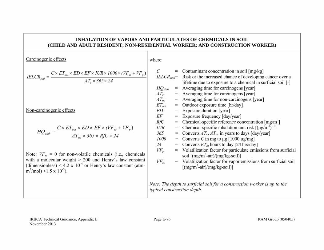
IRBCA Technical Guidance, Appendix E Page E-76 RAM Group (050405) November 2013
INHALATION OF VAPORS AND PARTICULATES OF CHEMICALS IN SOIL (CHILD AND ADULT RESIDENT; NON-RESIDENTIAL WORKER; AND CONSTRUCTION WORKER)
Carcinogenic effects
24365 ATVF(VF1000IUR EF EDET C
= IELCRc
pssoutsinh
)
Non-carcinogenic effects
24RfC 365 ATVF(VFEF EDETC
= HQnc
pssoutsinh
)
Note: VFss = 0 for non-volatile chemicals (i.e., chemicals with a molecular weight > 200 and Henry’s law constant (dimensionless) < 4.2 x 10⁻⁴ or Henry’s law constant (atm-m3/mol) <1.5 x 10⁻⁵).
where: C = Contaminant concentration in soil [mg/kg] IELCRsinh= Risk or the increased chance of developing cancer over a
lifetime due to exposure to a chemical in surficial soil [-] HQsinh = Averaging time for carcinogens [year] ATc = Averaging time for carcinogens [year] ATnc = Averaging time for non-carcinogens [year] ETout = Outdoor exposure time [hr/day] ED = Exposure duration [year] EF = Exposure frequency [day/year] RfC = Chemical-specific reference concentration [mg/m3] IUR = Chemical-specific inhalation unit risk [(μg/m3) -1] 365 = Converts ATc, ATnc in years to days [day/year] 1000 = Converts C in mg to μg [1000 μg/mg] 24 = Converts ETin hours to day [24 hrs/day] VFp = Volatilization factor for particulate emissions from surficial
soil [(mg/m3-air)/(mg/kg-soil)] VFss = Volatilization factor for vapor emissions from surficial soil
[(mg/m3-air)/(mg/kg-soil)] Note: The depth to surficial soil for a construction worker is up to the typical construction depth.
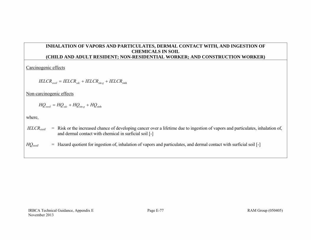
IRBCA Technical Guidance, Appendix E Page E-77 RAM Group (050405) November 2013
INHALATION OF VAPORS AND PARTICULATES, DERMAL CONTACT WITH, AND INGESTION OF CHEMICALS IN SOIL
(CHILD AND ADULT RESIDENT; NON-RESIDENTIAL WORKER; AND CONSTRUCTION WORKER)
Carcinogenic effects
sinhsin IELCRIELCRIELCRIELCR gsdcssoil
Non-carcinogenic effects sinhsin HQHQHQHQ gsdcssoil
where, IELCRssoil = Risk or the increased chance of developing cancer over a lifetime due to ingestion of vapors and particulates, inhalation of,
and dermal contact with chemical in surficial soil [-] HQssoil = Hazard quotient for ingestion of, inhalation of vapors and particulates, and dermal contact with surficial soil [-]
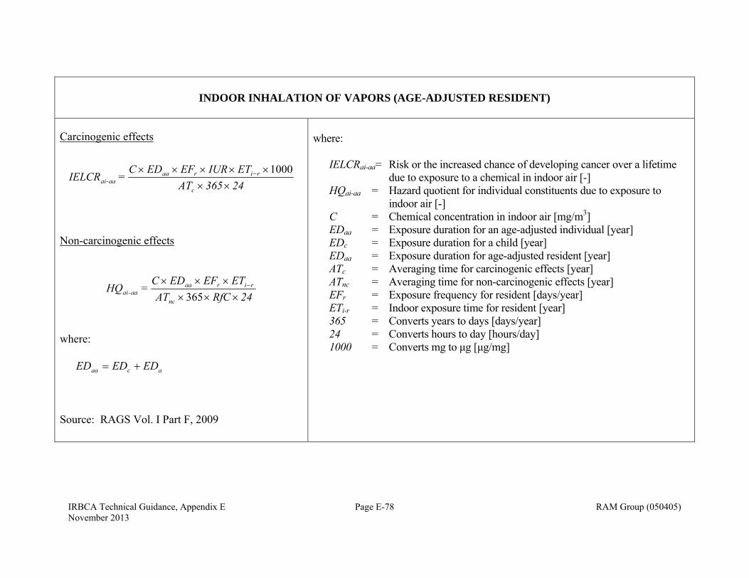
IRBCA Technical Guidance, Appendix E Page E-78 RAM Group (050405) November 2013
INDOOR INHALATION OF VAPORS (AGE-ADJUSTED RESIDENT)
Carcinogenic effects
24365 ATETIUREFEDC
= IELCRc
riraaaa-ai
1000
Non-carcinogenic effects
24RfCATETEFEDC
=HQnc
riraaaa-ai
365
where: acaa EDEDED
Source: RAGS Vol. I Part F, 2009
where: IELCRai-aa= Risk or the increased chance of developing cancer over a lifetime
due to exposure to a chemical in indoor air [-] HQai-aa = Hazard quotient for individual constituents due to exposure to
indoor air [-] C = Chemical concentration in indoor air [mg/m3] EDaa = Exposure duration for an age-adjusted individual [year] EDc = Exposure duration for a child [year] EDaa = Exposure duration for age-adjusted resident [year] ATc = Averaging time for carcinogenic effects [year] ATnc = Averaging time for non-carcinogenic effects [year] EFr = Exposure frequency for resident [days/year] ETi-r = Indoor exposure time for resident [year] 365 = Converts years to days [days/year] 24 = Converts hours to day [hours/day] 1000 = Converts mg to μg [μg/mg]

IRBCA Technical Guidance, Appendix E Page E-79 RAM Group (050405) November 2013
OUTDOOR INHALATION OF VAPORS (AGE-ADJUSTED RESIDENT)
Carcinogenic effects
24365 ATETIUREFEDC
= IELCRc
routraaaa-ai
1000
Non-carcinogenic effects
24RfCATETEFEDC
=HQnc
routraaaa-ai
365
where: acaa EDEDED
Source: RAGS Vol. I Part F, 2009
where: IELCRai-aa= Risk or the increased chance of developing cancer over a lifetime
due to exposure to a chemical in indoor air [-] HQai-aa = Hazard quotient for individual constituents due to exposure to
indoor air [-] C = Chemical concentration in indoor air [mg/m3] EDaa = Exposure duration for an age-adjusted individual [year] EDc = Exposure duration for a child [year] EDaa = Exposure duration for age-adjusted resident [year] ATc = Averaging time for carcinogenic effects [year] ATnc = Averaging time for non-carcinogenic effects [year] EFr = Exposure frequency for resident [days/year] ETout-r = Outdoor exposure time for resident [year] 365 = Converts years to days year [days/year] 24 = Converts hours to day [hours/day] 1000 = Converts mg to μg [μg/mg]
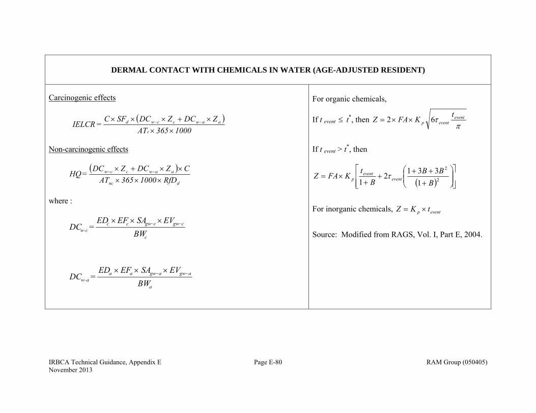
IRBCA Technical Guidance, Appendix E Page E-80 RAM Group (050405) November 2013
DERMAL CONTACT WITH CHEMICALS IN WATER (AGE-ADJUSTED RESIDENT)
Carcinogenic effects
1000365 ATZDCZDCSFC
=IELCRc
aawccwd
Non-carcinogenic effects
dnc
aawccw
RfD1000 365ATCZDCZDC
= HQ
where :
c
cgwcgwccc-w BW
EVSAEFED = DC
a
agwagwaaa-w BW
EVSAEFED = DC
For organic chemicals,
If t event t*, then
eventeventp
tKFAZ 62
If t event > t*, then
2
2
1
3312
1 BBB
Bt
KFAZ eventevent
p
For inorganic chemicals, eventp tKZ
Source: Modified from RAGS, Vol. I, Part E, 2004.
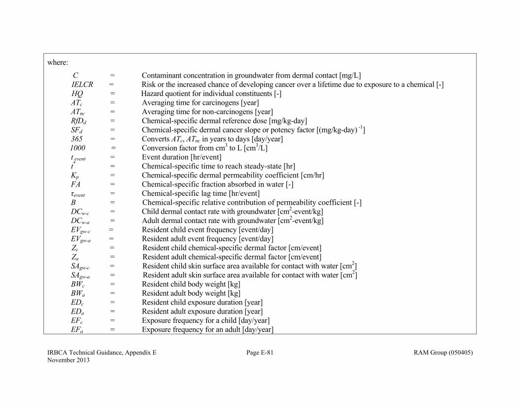
IRBCA Technical Guidance, Appendix E Page E-81 RAM Group (050405) November 2013
where:
C = Contaminant concentration in groundwater from dermal contact [mg/L] IELCR = Risk or the increased chance of developing cancer over a lifetime due to exposure to a chemical [-] HQ = Hazard quotient for individual constituents [-] ATc = Averaging time for carcinogens [year] ATnc = Averaging time for non-carcinogens [year] RfDd = Chemical-specific dermal reference dose [mg/kg-day] SFd = Chemical-specific dermal cancer slope or potency factor [(mg/kg-day) -1]
365 = Converts ATc, ATnc in years to days [day/year] 1000 = Conversion factor from cm3 to L [cm3/L]
t event = Event duration [hr/event] t* = Chemical-specific time to reach steady-state [hr] Kp = Chemical-specific dermal permeability coefficient [cm/hr] FA = Chemical-specific fraction absorbed in water [-] τevent = Chemical-specific lag time [hr/event] B = Chemical-specific relative contribution of permeability coefficient [-]
DCw-c = Child dermal contact rate with groundwater [cm2-event/kg] DCw-a = Adult dermal contact rate with groundwater [cm2-event/kg]
EVgw-c = Resident child event frequency [event/day] EVgw-a = Resident adult event frequency [event/day]
Zc = Resident child chemical-specific dermal factor [cm/event] Za = Resident adult chemical-specific dermal factor [cm/event]
SAgw-c = Resident child skin surface area available for contact with water [cm2] SAgw-a = Resident adult skin surface area available for contact with water [cm2]
BWc = Resident child body weight [kg] BWa = Resident adult body weight [kg] EDc = Resident child exposure duration [year] EDa = Resident adult exposure duration [year] EFc = Exposure frequency for a child [day/year] EFa = Exposure frequency for an adult [day/year]
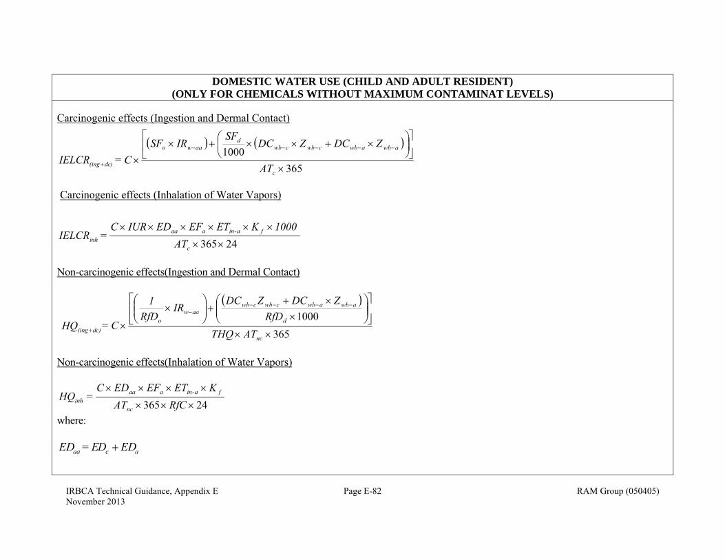
IRBCA Technical Guidance, Appendix E Page E-82 RAM Group (050405) November 2013
DOMESTIC WATER USE (CHILD AND ADULT RESIDENT) (ONLY FOR CHEMICALS WITHOUT MAXIMUM CONTAMINAT LEVELS)
Carcinogenic effects (Ingestion and Dermal Contact)
365
1000
c
awbawbcwbcwbd
aawo
dc)(ing AT
ZDCZDCSF
IRSFC = IELCR
Carcinogenic effects (Inhalation of Water Vapors)
24365
c
fa-inaaainh AT
1000KETEFEDIURC = IELCR
Non-carcinogenic effects(Ingestion and Dermal Contact)
365
1000
nc
d
awbawbcwbcwbaaw
odc)(ing ATTHQ
RfDZDCZDC
IRRfD
1
C = HQ
Non-carcinogenic effects(Inhalation of Water Vapors)
24365
RfCATKETEFEDC
=HQnc
fa-inaaainh
where:
acaa EDDE = ED
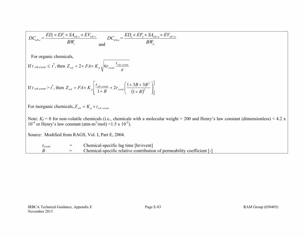
IRBCA Technical Guidance, Appendix E Page E-83 RAM Group (050405) November 2013
c
cwbcwbccc-wb BW
EVSAEFED = DC
and a
awbawbaaa-wb BW
EVSAEFED = DC
For organic chemicals,
If t wb-event t*, then
eventwbeventpwb
tKFAZ 62
If t wb-event > t*, then
2
2
1
3312
1 BBB
Bt
KFAZ eventeventwb
pwb
For inorganic chemicals, eventwbpwb tKZ
Note: Kf = 0 for non-volatile chemicals (i.e., chemicals with a molecular weight > 200 and Henry’s law constant (dimensionless) < 4.2 x 10⁻⁴ or Henry’s law constant (atm-m3/mol) <1.5 x 10⁻⁵). Source: Modified from RAGS, Vol. I, Part E, 2004. τevent = Chemical-specific lag time [hr/event] B = Chemical-specific relative contribution of permeability coefficient [-]

IRBCA Technical Guidance, Appendix E Page E-84 RAM Group (050405) November 2013
where: Cw = Contaminant concentration in domestic water [mg/L-H2O] IELCR(ing+dc) = Risk or the increased chance of developing cancer over a lifetime due to ingestion and dermal exposure to a
chemical in domestic water [-] IELCRinh = Risk or the increased chance of developing cancer over a lifetime due to inhalation of vapors from domestic
water use [-] HQ(ing+dc) = Hazard quotient for to ingestion and dermal exposure to a chemical in domestic water [-] HQinh = Hazard quotient for exposure to inhalation of chemical vapors due to domestic water use [-] ATc = Averaging time for non-carcinogens [year] ATnc = Averaging time for non-carcinogens [year] RfDo = Chemical-specific oral reference dose [mg/kg-day] RfC = Chemical-specific inhalation reference concentration [mg/m3] RfDd = Chemical-specific dermal reference dose [mg/kg-day] SFo = Chemical-specific oral cancer slope or potency factor [(mg/kg-day) -1]
IUR = Chemical-specific inhalation unit risk [(μg/m3) -1] SFd = Chemical-specific dermal cancer slope or potency factor [mg/(kg-day)]-1 IRw-aa = Age-adjusted groundwater ingestion rate [L/kg] IRw-c = Resident child groundwater ingestion rate [L/day] IRw- a = Resident adult groundwater ingestion rate [L/day] DCwb-c = Child dermal whole-body contact rate with groundwater [cm2-event/kg] DCwb-a = Adult dermal whole-body contact rate with groundwater [cm2-event/kg] BWc = Resident child body weight [kg] BWa = Resident adult body weight [kg] EDc = Resident child exposure duration [year] EDa = Resident adult exposure duration [year] EDaa = Resident age-adjusted exposure duration [year] EFa = Exposure frequency for an adult [day/year] ETa = Exposure frequency for an adult [day/year] Kf = Volatilization factor [L/m3] SAwb = Skin surface area available for whole-body contact with water [cm2]

IRBCA Technical Guidance, Appendix E Page E-85 RAM Group (050405) November 2013
EVwb = Event frequency for whole-body contact with water [event/day] 365 = Conversion factor [day/year] 1000 = Conversion factor from cm3 to L [cm3/L]; and mg μg [μg/mg] t wb-event = Event duration for whole-body contact [hr/event] t* = Chemical-specific time to reach steady-state [hr] Zwb = Chemical-specific dermal factor for whole-body contact [cm/event] Kp = Chemical-specific dermal permeability coefficient [cm/hr] FA = Chemical-specific fraction absorbed in water [-] τevent = Chemical-specific lag time [hr/event] B = Chemical-specific relative contribution of permeability coefficient [-] For inhalation of vapors, dermal contact with, and ingestion of chemicals in water (domestic water use combined pathway) by age-adjusted resident,
inhdcingaaw IELCRIELCRIELCR )(
inhdcingaaw HQHQHQ )(
where, IELCRw-aa = Risk or increased chance of developing cancer over a lifetime due to ingestion, dermal contact with, and
inhalation of chemicals in domestic water [-] HQw-aa = Hazard quotient for ingestion of, dermal contact with, and inhalation of chemicals in domestic water
[-]
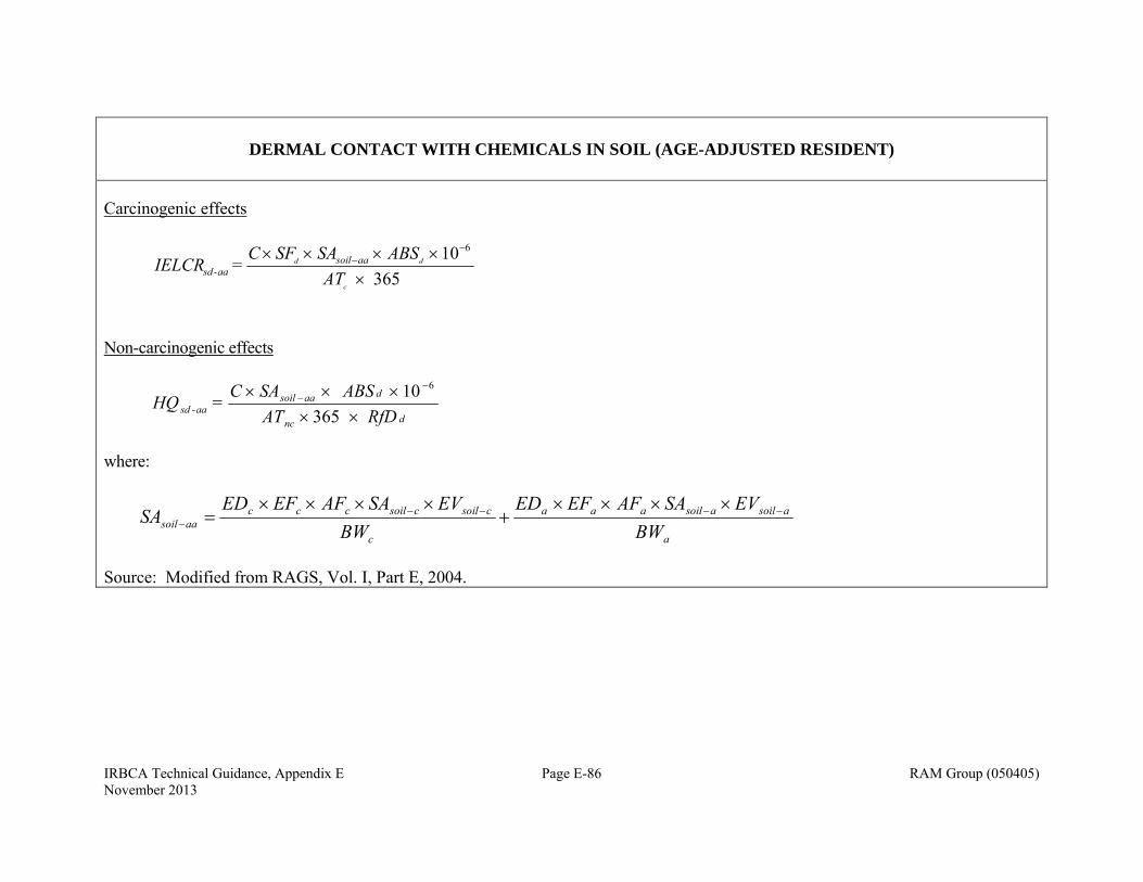
IRBCA Technical Guidance, Appendix E Page E-86 RAM Group (050405) November 2013
DERMAL CONTACT WITH CHEMICALS IN SOIL (AGE-ADJUSTED RESIDENT)
Carcinogenic effects
365
10 6
ATABSSASFC
= IELCRc
dd aasoilaa-sd
Non-carcinogenic effects
dnc
daasoilaa-sd RfD AT
ABSSAC = HQ
365
10 6
where:
a
asoilasoilaaa
c
csoilcsoilcccaasoil BW
EVSAAFEFEDBW
EVSAAFEFEDSA
Source: Modified from RAGS, Vol. I, Part E, 2004.
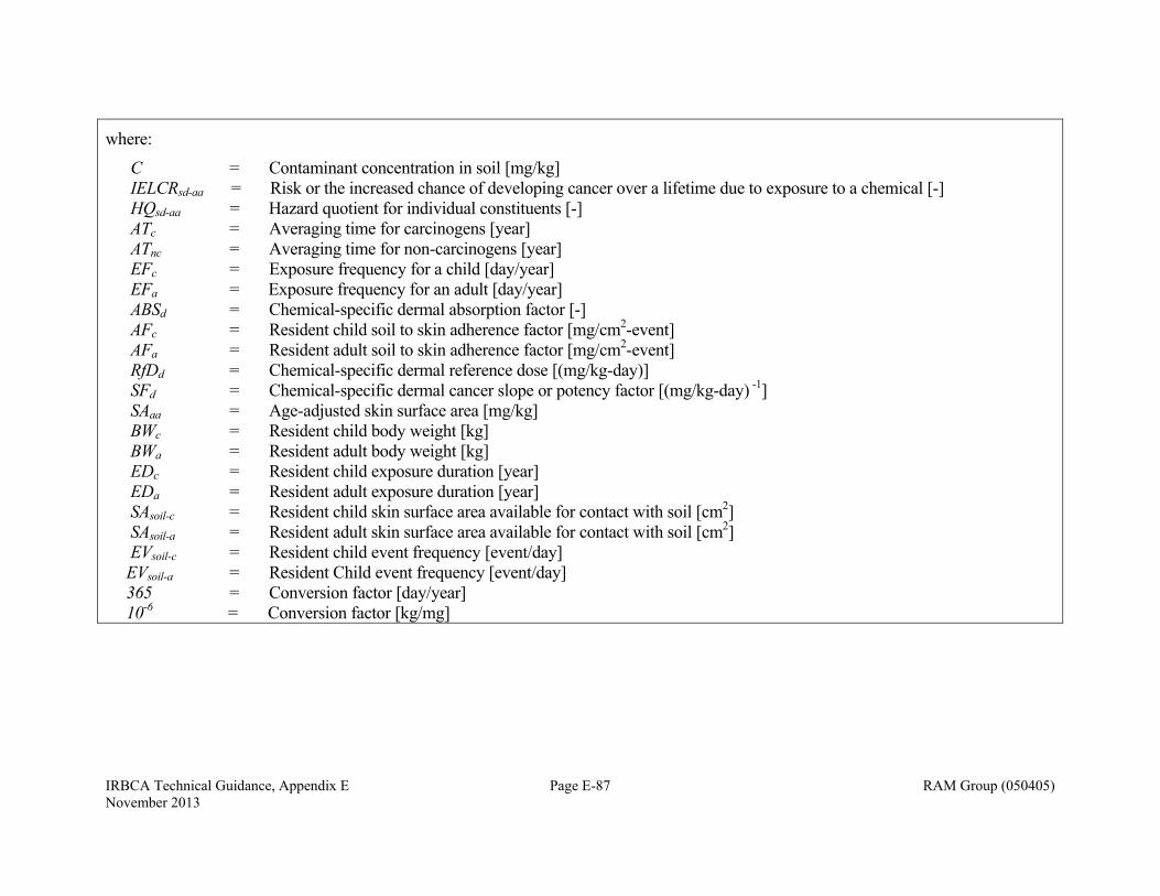
IRBCA Technical Guidance, Appendix E Page E-87 RAM Group (050405) November 2013
where:
C = Contaminant concentration in soil [mg/kg] IELCRsd-aa = Risk or the increased chance of developing cancer over a lifetime due to exposure to a chemical [-] HQsd-aa = Hazard quotient for individual constituents [-] ATc = Averaging time for carcinogens [year] ATnc = Averaging time for non-carcinogens [year] EFc = Exposure frequency for a child [day/year] EFa = Exposure frequency for an adult [day/year] ABSd = Chemical-specific dermal absorption factor [-] AFc = Resident child soil to skin adherence factor [mg/cm2-event] AFa = Resident adult soil to skin adherence factor [mg/cm2-event]
RfDd = Chemical-specific dermal reference dose [(mg/kg-day)] SFd = Chemical-specific dermal cancer slope or potency factor [(mg/kg-day) -1] SAaa = Age-adjusted skin surface area [mg/kg] BWc = Resident child body weight [kg] BWa = Resident adult body weight [kg] EDc = Resident child exposure duration [year] EDa = Resident adult exposure duration [year] SAsoil-c = Resident child skin surface area available for contact with soil [cm2] SAsoil-a = Resident adult skin surface area available for contact with soil [cm2] EVsoil-c = Resident child event frequency [event/day] EVsoil-a = Resident Child event frequency [event/day] 365 = Conversion factor [day/year] 10-6 = Conversion factor [kg/mg]

IRBCA Technical Guidance, Appendix E Page E-88 RAM Group (050405) November 2013
INGESTION OF CHEMICALS IN SOIL (AGE-ADJUSTED RESIDENT)
Carcinogenic effects
365
10 6
sin
c
aasaag AT
IRSFCIELCR O
Non-carcinogenic effects
onc
aasaag RfDAT
IRCHQ
365
10 6
sin
where :
a
asaa
c
csccaas BW
IREFEDBW
IREFEDIR
Source: Modified from RAGS, Vol. I, Part A, 1989

IRBCA Technical Guidance, Appendix E Page E-89 RAM Group (050405) November 2013
where:
C = Contaminant concentration in soil [mg/kg-wet soil] IELCRsing-aa = Risk or the increased chance of developing cancer over a lifetime due to exposure to a chemical [-] HQsing-aa = Hazard quotient for individual constituents [-] ATc = Averaging time for carcinogens [year] ATnc = Averaging time for non-carcinogens [year]
RfDo = Chemical-specific oral reference dose [mg/kg-day] SFo = Chemical-specific oral cancer slope or potency factor [(mg/kg-day) -1] IRs -aa = Age-adjusted soil ingestion rate [mg/kg] IRs-c = Resident child soil ingestion rate [mg/day] IRs-a = Resident adult soil ingestion rate [mg/day] BWc = Resident child body weight [kg] BWa = Resident adult body weight [kg] EDc = Resident child exposure duration [year] EDa = Resident adult exposure duration [year]
EFc = Exposure frequency for a child [day/year] EFa = Exposure frequency for an adult [day/year]
365 = Conversion factor [day/year] 10-6 = Conversion factor [kg/mg]
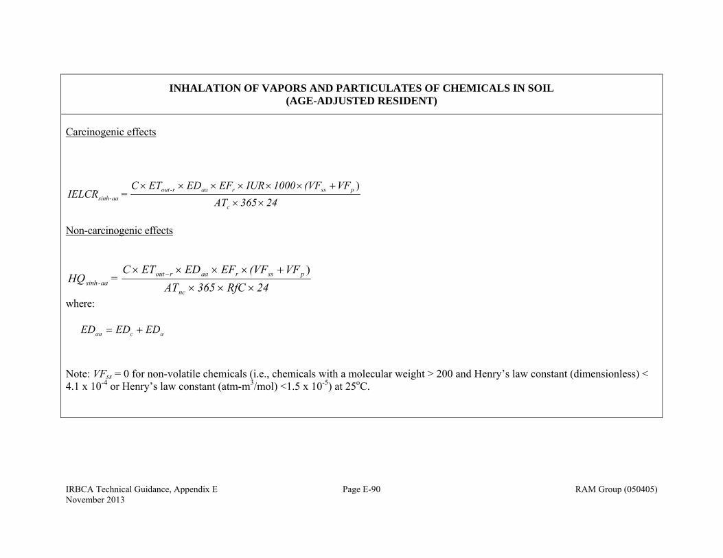
IRBCA Technical Guidance, Appendix E Page E-90 RAM Group (050405) November 2013
INHALATION OF VAPORS AND PARTICULATES OF CHEMICALS IN SOIL (AGE-ADJUSTED RESIDENT)
Carcinogenic effects
24365 ATVF(VF1000IUR EF EDET C
= IELCRc
pssraar-outaa-sinh
)
Non-carcinogenic effects
24RfC 365 ATVF(VFEF EDETC
= HQnc
pssraaroutaa-sinh
)
where: acaa EDEDED
Note: VFss = 0 for non-volatile chemicals (i.e., chemicals with a molecular weight > 200 and Henry’s law constant (dimensionless) < 4.1 x 10⁻⁴ or Henry’s law constant (atm-m3/mol) <1.5 x 10⁻⁵) at 25oC.
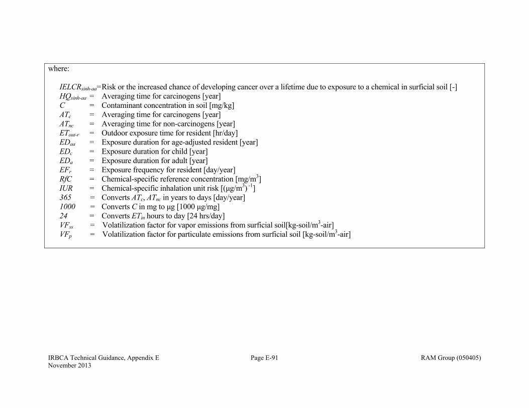
IRBCA Technical Guidance, Appendix E Page E-91 RAM Group (050405) November 2013
where: IELCRsinh-aa= Risk or the increased chance of developing cancer over a lifetime due to exposure to a chemical in surficial soil [-] HQsinh-aa = Averaging time for carcinogens [year] C = Contaminant concentration in soil [mg/kg] ATc = Averaging time for carcinogens [year] ATnc = Averaging time for non-carcinogens [year] ETout-r = Outdoor exposure time for resident [hr/day] EDaa = Exposure duration for age-adjusted resident [year] EDc = Exposure duration for child [year] EDa = Exposure duration for adult [year] EFr = Exposure frequency for resident [day/year] RfC = Chemical-specific reference concentration [mg/m3] IUR = Chemical-specific inhalation unit risk [(μg/m3) -1] 365 = Converts ATc, ATnc in years to days [day/year] 1000 = Converts C in mg to μg [1000 μg/mg] 24 = Converts ETin hours to day [24 hrs/day] VFss = Volatilization factor for vapor emissions from surficial soil[kg-soil/m3-air]
VFp = Volatilization factor for particulate emissions from surficial soil [kg-soil/m3-air]
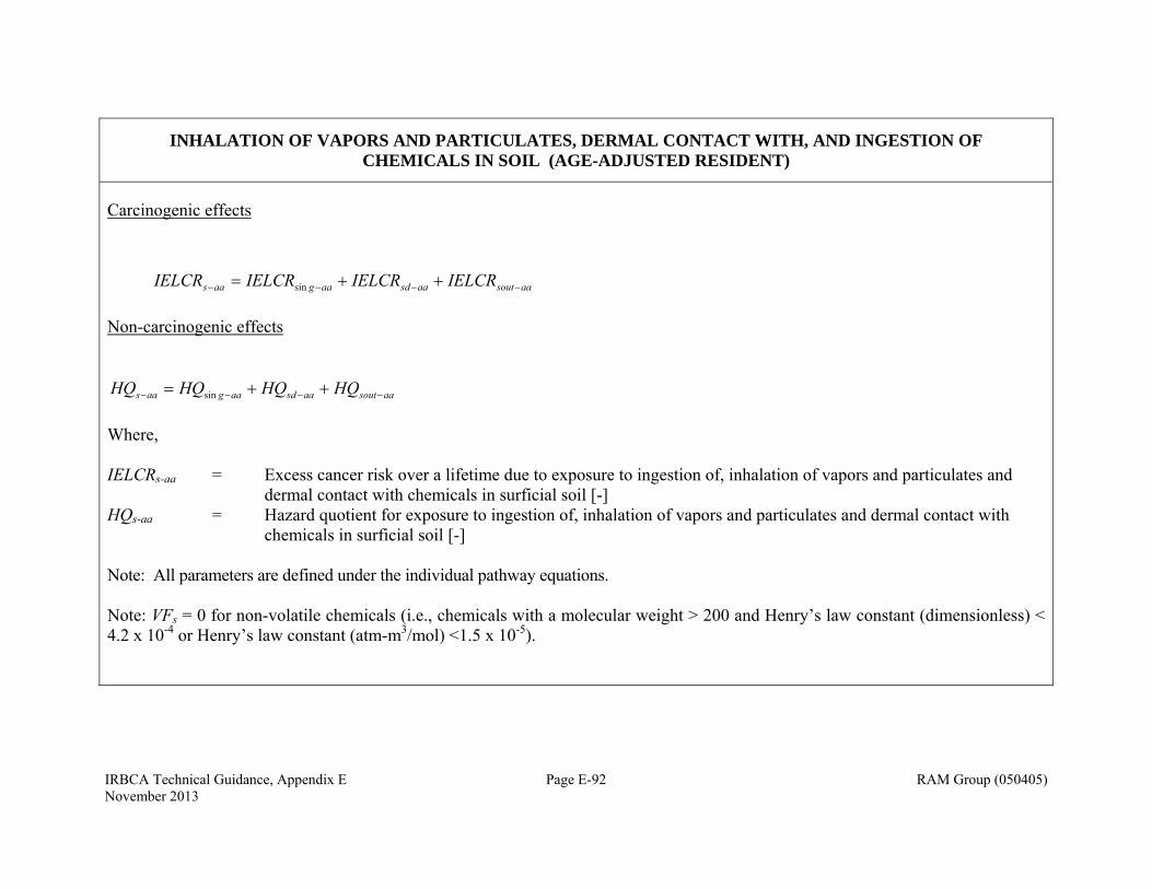
IRBCA Technical Guidance, Appendix E Page E-92 RAM Group (050405) November 2013
INHALATION OF VAPORS AND PARTICULATES, DERMAL CONTACT WITH, AND INGESTION OF CHEMICALS IN SOIL (AGE-ADJUSTED RESIDENT)
Carcinogenic effects
aasoutaasdaagaas IELCRIELCRIELCRIELCR sin
Non-carcinogenic effects
aasoutaasdaagaas HQHQHQHQ sin
Where, IELCRs-aa = Excess cancer risk over a lifetime due to exposure to ingestion of, inhalation of vapors and particulates and dermal contact with chemicals in surficial soil [-] HQs-aa = Hazard quotient for exposure to ingestion of, inhalation of vapors and particulates and dermal contact with chemicals in surficial soil [-] Note: All parameters are defined under the individual pathway equations. Note: VFs = 0 for non-volatile chemicals (i.e., chemicals with a molecular weight > 200 and Henry’s law constant (dimensionless) < 4.2 x 10⁻⁴ or Henry’s law constant (atm-m3/mol) <1.5 x 10⁻⁵).

IRBCA Technical Guidance, Appendix E Page E-93 RAM Group (050405) November 2013
INDOOR AIR CONCENTRATION ESTIMATED FROM SUBSURFACE SOIL VAPOR CONCENTRATIONS
svsviai CC
where: Cai = Indoor air concentration [mg/m3-air] Csvi = Soil vapor concentration [mg/m3-air] αsv = Attenuation factor from subsurface soil vapor to
indoor (enclosed space) air [-] Source: ASTM E1739-95
Ground surface
Vadose zone
Water Table
Enclosed Space Foundation Cracks
Dissolved contaminants
ERLB
Subsurface impacted
Diffusing vapors
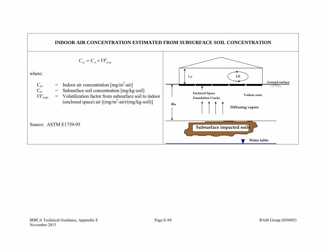
IRBCA Technical Guidance, Appendix E Page E-94 RAM Group (050405) November 2013
INDOOR AIR CONCENTRATION ESTIMATED FROM SUBSURFACE SOIL CONCENTRATION
sespsiai VFCC
where: Cai = Indoor air concentration [mg/m3-air] Csi = Subsurface soil concentration [mg/kg-soil] VFsesp = Volatilization factor from subsurface soil to indoor
(enclosed space) air [(mg/m3-air)/(mg/kg-soil)] Source: ASTM E1739-95
dts Diffusing vapors
Water table
Subsurface impacted soils
Ground surface
Vadose zone Enclosed Space Foundation Cracks
ER L B
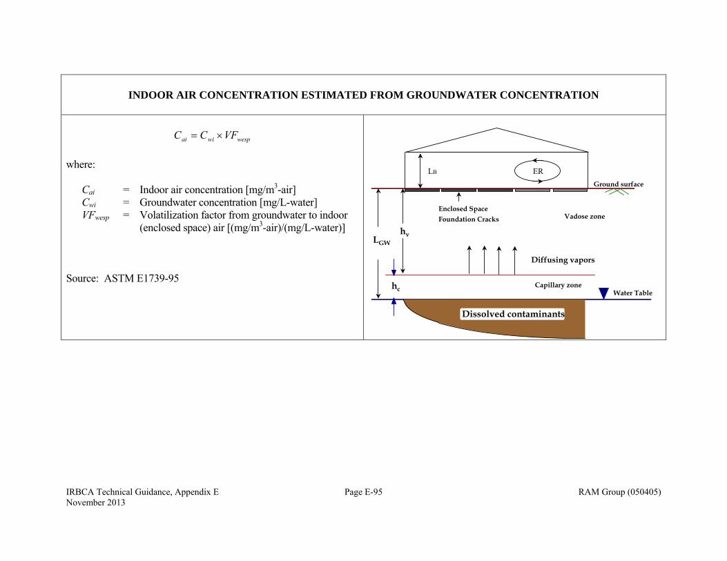
IRBCA Technical Guidance, Appendix E Page E-95 RAM Group (050405) November 2013
INDOOR AIR CONCENTRATION ESTIMATED FROM GROUNDWATER CONCENTRATION
wespwiai VFCC
where: Cai = Indoor air concentration [mg/m3-air] Cwi = Groundwater concentration [mg/L-water] VFwesp = Volatilization factor from groundwater to indoor
(enclosed space) air [(mg/m3-air)/(mg/L-water)] Source: ASTM E1739-95
Ground surface
Capillary zone
hvLGW
Vadose zone
Water Table
Enclosed Space
Dissolved contaminants
Diffusing vapors
hc
Foundation Cracks
ERLB
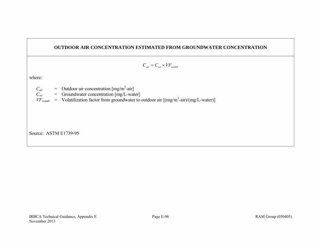
IRBCA Technical Guidance, Appendix E Page E-96 RAM Group (050405) November 2013
OUTDOOR AIR CONCENTRATION ESTIMATED FROM GROUNDWATER CONCENTRATION
wambwiao VFCC
where: Cao = Outdoor air concentration [mg/m3-air] Cwi = Groundwater concentration [mg/L-water] VFwamb = Volatilization factor from groundwater to outdoor air [(mg/m3-air)/(mg/L-water)] Source: ASTM E1739-95
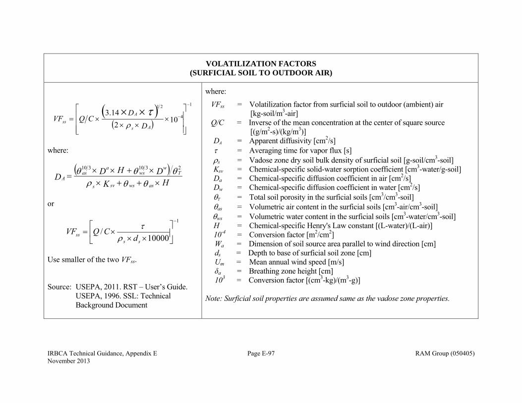
IRBCA Technical Guidance, Appendix E Page E-97 RAM Group (050405) November 2013
VOLATILIZATION FACTORS (SURFICIAL SOIL TO OUTDOOR AIR)
1
4
21
102
14.3
D
DCQVF
As
Ass
where:
HKDHDD
aswssvs
Tw
wsa
asA
2310310
or
1
10000/
ss
ss dCQVF
Use smaller of the two VFss. Source: USEPA, 2011. RST – User’s Guide. USEPA, 1996. SSL: Technical Background Document
where:
VFss = Volatilization factor from surficial soil to outdoor (ambient) air [kg-soil/m3-air] Q/C = Inverse of the mean concentration at the center of square source [(g/m2-s)/(kg/m3)] DA = Apparent diffusivity [cm2/s] = Averaging time for vapor flux [s] s = Vadose zone dry soil bulk density of surficial soil [g-soil/cm3-soil] Ksv = Chemical-specific solid-water sorption coefficient [cm3-water/g-soil] Da = Chemical-specific diffusion coefficient in air [cm2/s] Dw = Chemical-specific diffusion coefficient in water [cm2/s] T = Total soil porosity in the surficial soils [cm3/cm3-soil] as = Volumetric air content in the surficial soils [cm3-air/cm3-soil] ws = Volumetric water content in the surficial soils [cm3-water/cm3-soil] H = Chemical-specific Henry's Law constant [(L-water)/(L-air)] 10-4 = Conversion factor [m2/cm2] Wa = Dimension of soil source area parallel to wind direction [cm] ds = Depth to base of surficial soil zone [cm] Um = Mean annual wind speed [m/s] δa = Breathing zone height [cm] 103 = Conversion factor [(cm3-kg)/(m3-g)] Note: Surficial soil properties are assumed same as the vadose zone properties.
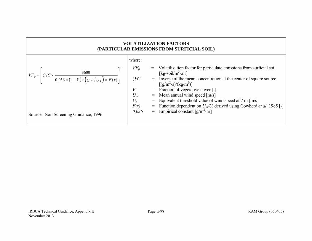
IRBCA Technical Guidance, Appendix E Page E-98 RAM Group (050405) November 2013
VOLATILIZATION FACTORS (PARTICULAR EMISSIONS FROM SURFICIAL SOIL)
1
3)(1036.0
3600
xFU tU mVCQVF p
Source: Soil Screening Guidance, 1996
where:
VFp = Volatilization factor for particulate emissions from surficial soil [kg-soil/m3-air]
Q/C = Inverse of the mean concentration at the center of square source [(g/m2-s)/(kg/m3)]
V = Fraction of vegetative cover [-] Um = Mean annual wind speed [m/s] Ut = Equivalent threshold value of wind speed at 7 m [m/s] F(x) = Function dependent on Um/Ut derived using Cowherd et al. 1985 [-] 0.036 = Empirical constant [g/m2-hr]

IRBCA Technical Guidance, Appendix E Page E-99 RAM Group (050405) November 2013
VOLATILIZATION/ATTENUATION FACTORS (SUBSURFACE SOIL VAPOR TO INDOOR AIR)
For advection and diffusion,
1expexp
exp
crackeffcrack
cracksoil
Tsoil
BeffT
Tbldg
BeffT
crackeffcrack
cracksoil
crackeffcrack
cracksoil
Tbldg
BeffT
sv
ADLQ
LQAD
LQAD
ADLQ
ADLQ
LQAD
=
where,
FsourceT LDL
If LF > Lcrack, BFBFBBB WLLLWLA 22 If LF ≤ Lcrack, BBB WLA
3600
ERHWLQ BBBbldg
wWLA BBcrack 2
where, αsv = Attenuation factor for soil vapor to indoor air [-] DT
eff = Total overall effective diffusion coefficient [cm2/s] AB = Area of enclosed space below grade [cm2] Qbldg = Building ventilation rate [cm3/s] LT = Source to building separation [cm] Qsoil = Volumetric flow rate of soil-vapor into the
enclosed space [cm3/s] Lcrack = Slab thickness [cm] Dcrack
eff = Effective diffusion coefficient through the cracks [cm2/s]
Acrack = Area of total cracks [cm2] Dsource = Depth below grade to top of contamination [cm] LF = Depth below grade to bottom of enclosed space
floor [cm] LB = Length of building [cm] WB = Width of building [cm] Qbldg = Building ventilation rate [cm3/s] HB = Height of building [cm] ER = Air exchange rate [l/h] 3600 = Conversion factor [sec/h] ΔP = Soil-building pressure differential [g/cm-s2] kv = Soil gas permeability[cm2] Xcrack = Floor-wall seam perimeter [cm] µ = Viscosity of air at soil temperature [g/cm-s] rcrack = Equivalent crack radius [cm]
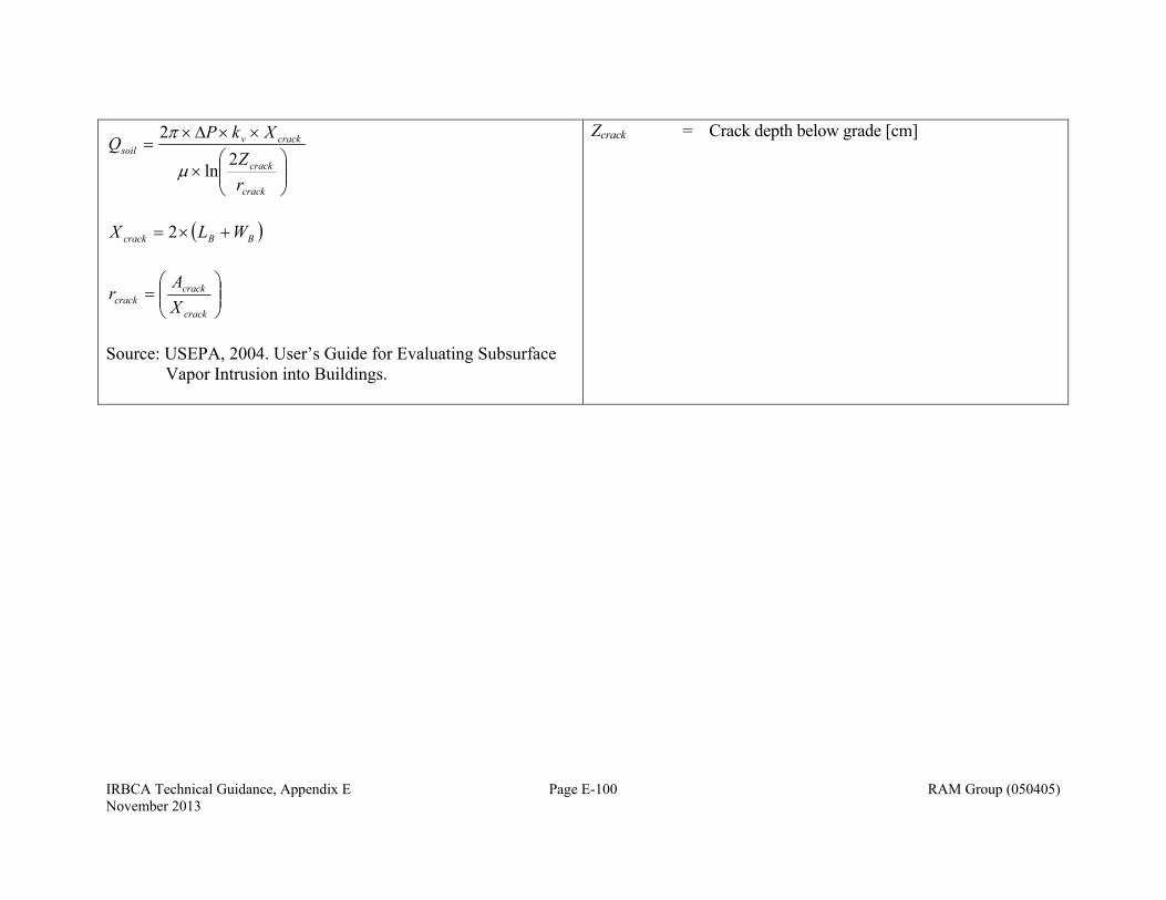
IRBCA Technical Guidance, Appendix E Page E-100 RAM Group (050405) November 2013
crack
crack
crackvsoil
rZ
XkPQ
2ln
2
BBcrack WLX 2
crack
crackcrack X
Ar
Source: USEPA, 2004. User’s Guide for Evaluating Subsurface
Vapor Intrusion into Buildings.
Zcrack = Crack depth below grade [cm]
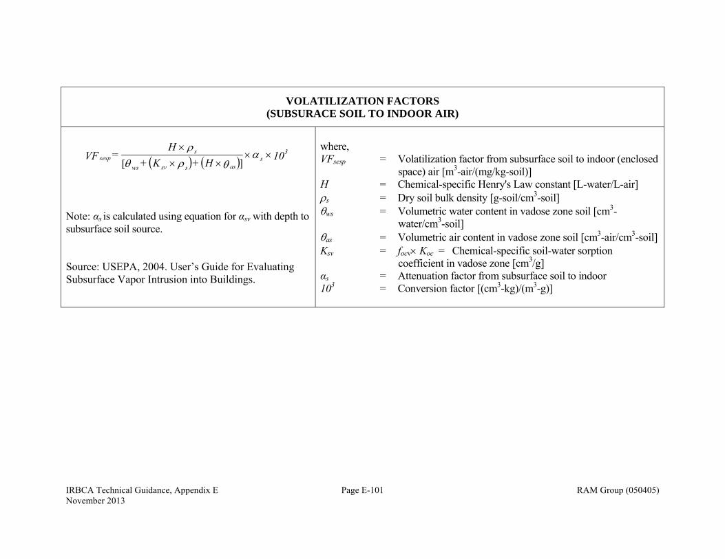
IRBCA Technical Guidance, Appendix E Page E-101 RAM Group (050405) November 2013
VOLATILIZATION FACTORS (SUBSURACE SOIL TO INDOOR AIR)
10 H + K +
H = VF 3
sasssvws
ssesp
][
Note: αs is calculated using equation for αsv with depth to subsurface soil source. Source: USEPA, 2004. User’s Guide for Evaluating Subsurface Vapor Intrusion into Buildings.
where, VFsesp = Volatilization factor from subsurface soil to indoor (enclosed
space) air [m3-air/(mg/kg-soil)] H = Chemical-specific Henry's Law constant [L-water/L-air] s = Dry soil bulk density [g-soil/cm3-soil] ws = Volumetric water content in vadose zone soil [cm3-
water/cm3-soil] as = Volumetric air content in vadose zone soil [cm3-air/cm3-soil] Ksv = focv Koc = Chemical-specific soil-water sorption
coefficient in vadose zone [cm3/g] αs = Attenuation factor from subsurface soil to indoor 103 = Conversion factor [(cm3-kg)/(m3-g)]
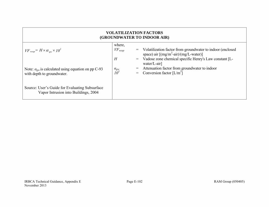
IRBCA Technical Guidance, Appendix E Page E-102 RAM Group (050405) November 2013
VOLATILIZATION FACTORS (GROUNDWATER TO INDOOR AIR)
10 H= VF 3gwwesp
Note: αgw is calculated using equation on pp C-93 with depth to groundwater. Source: User’s Guide for Evaluating Subsurface
Vapor Intrusion into Buildings, 2004
where, VFwesp = Volatilization factor from groundwater to indoor (enclosed
space) air [(mg/m3-air)/(mg/L-water)] H = Vadose zone chemical specific Henry's Law constant [L-
water/L-air] αgw = Attenuation factor from groundwater to indoor 103 = Conversion factor [L/m3]

IRBCA Technical Guidance, Appendix E Page E-103 RAM Group (050405) November 2013
VOLATILIZATION FACTORS (GROUNDWATER TO OUTDOOR AIR)
10
DWLU
H = VF 3
effwsga
GWam
wamb
100
1
Source: ASTM E1739-95
where:
VFwamb = Volatilization factor from groundwater to outdoor air [(mg/m3-air)/(mg/L-water)]
H = Vadose zone chemical specific Henry's Law constant [(L-water)/(L-air)] Um = Mean annual wind speed [m/s] δa = Breathing zone height [cm] LGW = Depth to groundwater [cm] Dws
eff = Effective diffusion coefficient between groundwater and soil surface [cm2/s]
Wga = Dimension of soil source area parallel to wind direction [cm] 100 = Conversion factor [cm/m] 103 = Conversion factor [L/m3]
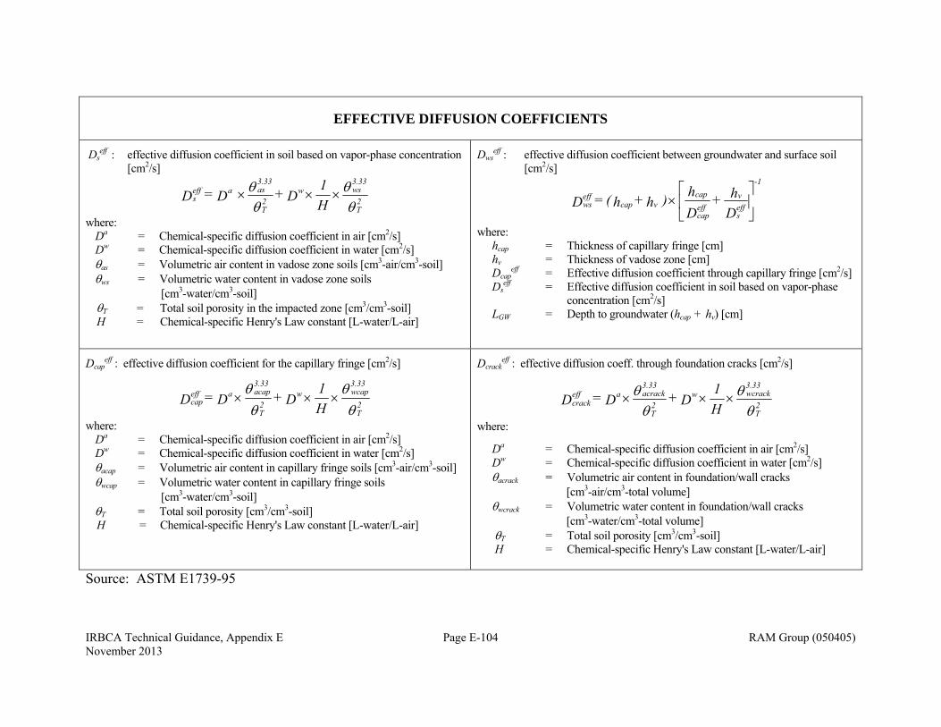
IRBCA Technical Guidance, Appendix E Page E-104 RAM Group (050405) November 2013
EFFECTIVE DIFFUSION COEFFICIENTS
Dseff : effective diffusion coefficient in soil based on vapor-phase concentration
[cm2/s]
2T
3.33wsw
2T
3.33asaeff
s H1 D + D = D
where: Da = Chemical-specific diffusion coefficient in air [cm2/s] Dw = Chemical-specific diffusion coefficient in water [cm2/s] as = Volumetric air content in vadose zone soils [cm3-air/cm3-soil] ws = Volumetric water content in vadose zone soils [cm3-water/cm3-soil] T = Total soil porosity in the impacted zone [cm3/cm3-soil] H = Chemical-specific Henry's Law constant [L-water/L-air]
Dwseff : effective diffusion coefficient between groundwater and surface soil
[cm2/s]
Dh +
Dh ) h + h( = D eff
s
veffcap
cap-1
vcapeffws
where: hcap = Thickness of capillary fringe [cm] hv = Thickness of vadose zone [cm] Dcap
eff = Effective diffusion coefficient through capillary fringe [cm2/s] Ds
eff = Effective diffusion coefficient in soil based on vapor-phase concentration [cm2/s]
LGW = Depth to groundwater (hcap + hv) [cm]
Dcapeff : effective diffusion coefficient for the capillary fringe [cm2/s]
2T
3.33wcapw
2T
3.33acapaeff
cap H1 D + D = D
where: Da = Chemical-specific diffusion coefficient in air [cm2/s] Dw = Chemical-specific diffusion coefficient in water [cm2/s] acap = Volumetric air content in capillary fringe soils [cm3-air/cm3-soil] wcap = Volumetric water content in capillary fringe soils [cm3-water/cm3-soil] T = Total soil porosity [cm3/cm3-soil] H = Chemical-specific Henry's Law constant [L-water/L-air]
Dcrackeff : effective diffusion coeff. through foundation cracks [cm2/s]
2T
3.33wcrackw
2T
3.33acrackaeff
crack H1 D + D = D
where:
Da = Chemical-specific diffusion coefficient in air [cm2/s] Dw = Chemical-specific diffusion coefficient in water [cm2/s] acrack = Volumetric air content in foundation/wall cracks [cm3-air/cm3-total volume] wcrack = Volumetric water content in foundation/wall cracks [cm3-water/cm3-total volume] T = Total soil porosity [cm3/cm3-soil] H = Chemical-specific Henry's Law constant [L-water/L-air]
Source: ASTM E1739-95

IRBCA Technical Guidance, Appendix E Page E-105 RAM Group (050405) November 2013
SUBSURFACE SOIL CONCENTRATION AT WHICH DISSOLVED PORE WATER AND VAPOR PHASES BECOME SATURATED
Single Component
][
ssvwsass
SATs KHS
C
Multiple Components
][
ssvwsass
eiSATs KH
SC
where: Cs
SAT = Soil concentration at which dissolved pore water and vapor phases become saturated [(mg/kg-soil)] S = Pure component solubility in water [mg/L-water] Sei = Effective solubility of component i in water = xi × S [mg/L-water] xi = Mole fraction of component i = (wi × MWavg)/MWi [-] wi = Weight fraction of component i [-] MWavg = Average molecular weight of mixture [g/mole] MWi = Molecular weight of component i [g/mole] s = Vadose zone dry soil bulk density [g-soil/cm3-soil] H = Chemical-specific Henry's Law constant [L-water/L-air] as = Volumetric air content in the vadose zone soils [cm3-air/cm3-soil] ws = Volumetric water content in vadose zone soils [cm3-water/cm3- soil] Ksv = focv Koc = Chemical-specific soil-water sorption coefficient in vadose zone [cm3-water/g-soil] focv = Fraction organic carbon in vadose zone [g-C/g-soil]
Source: ASTM E1739-95
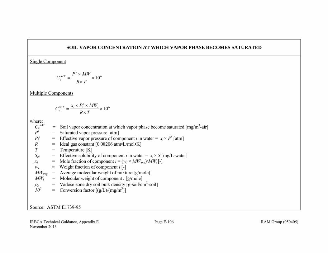
IRBCA Technical Guidance, Appendix E Page E-106 RAM Group (050405) November 2013
SOIL VAPOR CONCENTRATION AT WHICH VAPOR PHASE BECOMES SATURATED
Single Component
610
TRMWP
Cs
SATv
Multiple Components
610
TRMWPx
C is
iiSATv
where: Cv
SAT = Soil vapor concentration at which vapor phase become saturated [mg/m3-air] Ps = Saturated vapor pressure [atm] Pi
s = Effective vapor pressure of component i in water = xi × Ps [atm] R = Ideal gas constant [0.08206 atm•L/mol•K] T = Temperature [K] Sei = Effective solubility of component i in water = xi × S [mg/L-water] xi = Mole fraction of component i = (wi × MWavg)/MWi [-] wi = Weight fraction of component i [-] MWavg = Average molecular weight of mixture [g/mole] MWi = Molecular weight of component i [g/mole] s = Vadose zone dry soil bulk density [g-soil/cm3-soil] 106 = Conversion factor [(g/L)/(mg/m3)]
Source: ASTM E1739-95
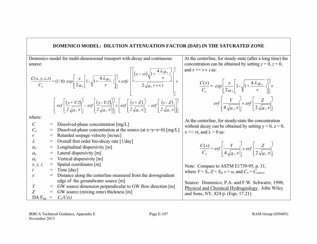
IRBCA Technical Guidance, Appendix E Page E-107 RAM Group (050405) November 2013
DOMENICO MODEL: DILUTION ATTENUATION FACTOR (DAF) IN THE SATURATED ZONE
Domenico model for multi-dimensional transport with decay and continuous source:
x 2 Z-z erf -
x 2 Z+z erf
x 2Y/2 -y erf -
x 2Y/2 +y erf
tv
vvtx
erfcv
xexpC
tzyxC
zzyy
o
2
4
+ 1
4
+ 1 - 1 2
)8/1( = ),,,(
x
x
x
x
where:
C = Dissolved-phase concentration [mg/L] Co = Dissolved-phase concentration at the source (at x=y=z=0) [mg/L] v = Retarded seepage velocity [m/sec] = Overall first order bio-decay rate [1/day] x = Longitudinal dispersivity [m] y = Lateral dispersivity [m] z = Vertical dispersivity [m] x, y, z = Spatial coordinates [m] t = Time [day] x = Distance along the centerline measured from the downgradient
edge of the groundwater source [m] Y = GW source dimension perpendicular to GW flow direction [m] Z = GW source (mixing zone) thickness [m] DA Fsat = Co/C(x)
At the centerline, for steady-state (after a long time) the concentration can be obtained by setting y = 0, z = 0, and x << v t as:
x Z erf
x Y erf
vxexp
CxC
zy
o
24
4
+ 1 - 1 2
= )( x
x
At the centerline, for steady-state the concentration without decay can be obtained by setting y = 0, z = 0, x << vt, and = 0 as:
x Z erf
x Y erf
CxC
zyo 24 =
)(
Note: Compare to ASTM E1739-95, p. 31, where Y = Sw Z = Sd, v = u, and Co = Csource Source: Domenico, P.A. and F.W. Schwartz, 1990, Physical and Chemical Hydrogeology. John Wiley and Sons, NY, 824 p. (Eqn. 17.21)
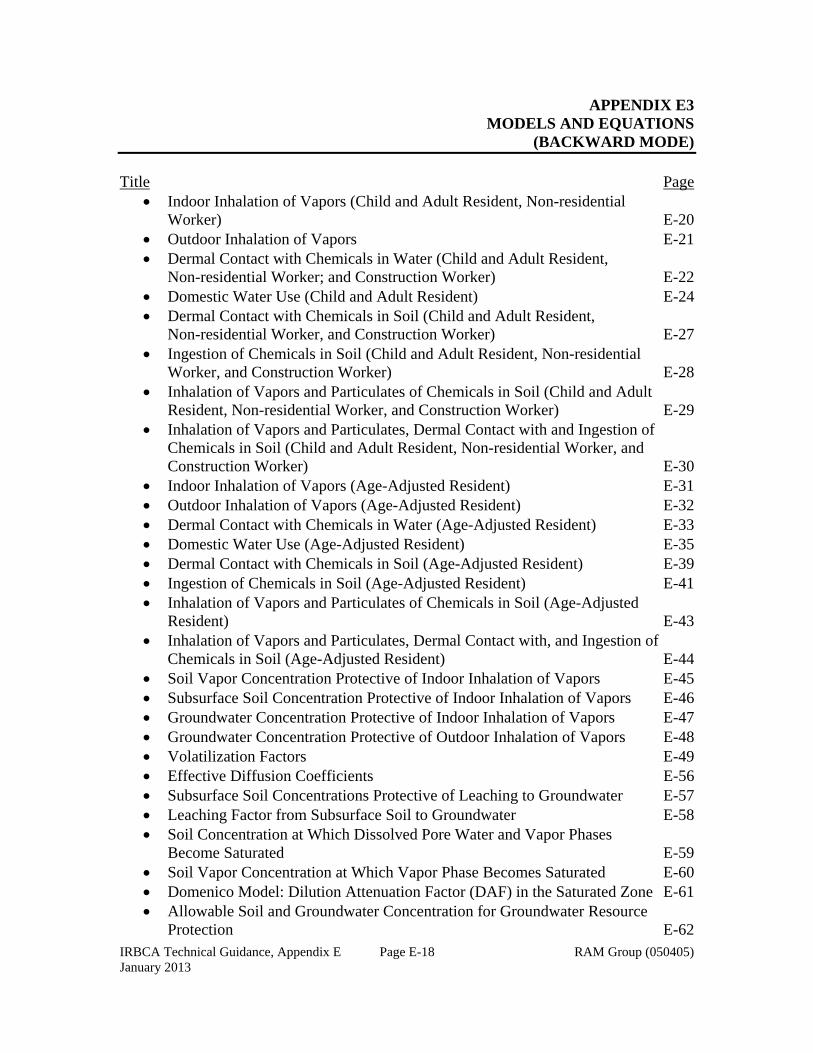
IRBCA Technical Guidance, Appendix E Page E-18 RAM Group (050405) January 2013
APPENDIX E3 MODELS AND EQUATIONS
(BACKWARD MODE) Title Page
Indoor Inhalation of Vapors (Child and Adult Resident, Non-residential Worker) E-20 Outdoor Inhalation of Vapors E-21 Dermal Contact with Chemicals in Water (Child and Adult Resident,
Non-residential Worker; and Construction Worker) E-22 Domestic Water Use (Child and Adult Resident) E-24 Dermal Contact with Chemicals in Soil (Child and Adult Resident,
Non-residential Worker, and Construction Worker) E-27 Ingestion of Chemicals in Soil (Child and Adult Resident, Non-residential
Worker, and Construction Worker) E-28 Inhalation of Vapors and Particulates of Chemicals in Soil (Child and Adult Resident, Non-residential Worker, and Construction Worker) E-29 Inhalation of Vapors and Particulates, Dermal Contact with and Ingestion of Chemicals in Soil (Child and Adult Resident, Non-residential Worker, and Construction Worker) E-30 Indoor Inhalation of Vapors (Age-Adjusted Resident) E-31 Outdoor Inhalation of Vapors (Age-Adjusted Resident) E-32 Dermal Contact with Chemicals in Water (Age-Adjusted Resident) E-33 Domestic Water Use (Age-Adjusted Resident) E-35 Dermal Contact with Chemicals in Soil (Age-Adjusted Resident) E-39 Ingestion of Chemicals in Soil (Age-Adjusted Resident) E-41 Inhalation of Vapors and Particulates of Chemicals in Soil (Age-Adjusted
Resident) E-43 Inhalation of Vapors and Particulates, Dermal Contact with, and Ingestion of
Chemicals in Soil (Age-Adjusted Resident) E-44 Soil Vapor Concentration Protective of Indoor Inhalation of Vapors E-45 Subsurface Soil Concentration Protective of Indoor Inhalation of Vapors E-46 Groundwater Concentration Protective of Indoor Inhalation of Vapors E-47 Groundwater Concentration Protective of Outdoor Inhalation of Vapors E-48 Volatilization Factors E-49 Effective Diffusion Coefficients E-56 Subsurface Soil Concentrations Protective of Leaching to Groundwater E-57 Leaching Factor from Subsurface Soil to Groundwater E-58 Soil Concentration at Which Dissolved Pore Water and Vapor Phases Become Saturated E-59 Soil Vapor Concentration at Which Vapor Phase Becomes Saturated E-60 Domenico Model: Dilution Attenuation Factor (DAF) in the Saturated Zone E-61 Allowable Soil and Groundwater Concentration for Groundwater Resource
Protection E-62

IRBCA Technical Guidance, Appendix E Page E-19 RAM Group (050405) January 2013
Allowable Soil and Groundwater Concentration Protective of Indoor Inhalation for Resident and Non-Residential Worker E-63
Stream Protection: Allowable Groundwater Concentration at the Point of Discharge E-64
Stream Protection: Allowable Groundwater Concentration at the Source and POD E-65
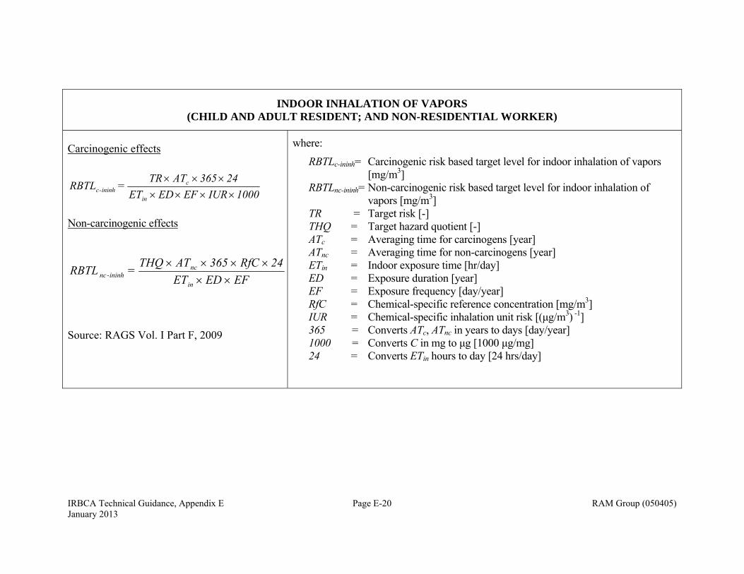
IRBCA Technical Guidance, Appendix E Page E-20 RAM Group (050405) January 2013
INDOOR INHALATION OF VAPORS (CHILD AND ADULT RESIDENT; AND NON-RESIDENTIAL WORKER)
Carcinogenic effects
1000IUR EF EDET24365 ATTR
= RBTLin
cininh-c
Non-carcinogenic effects
EF EDET24RfC 365 ATTHQ = RBTL
in
ncininh-nc
Source: RAGS Vol. I Part F, 2009
where:
RBTLc-ininh= Carcinogenic risk based target level for indoor inhalation of vapors [mg/m3]
RBTLnc-ininh= Non-carcinogenic risk based target level for indoor inhalation of vapors [mg/m3]
TR = Target risk [-] THQ = Target hazard quotient [-] ATc = Averaging time for carcinogens [year] ATnc = Averaging time for non-carcinogens [year] ETin = Indoor exposure time [hr/day] ED = Exposure duration [year] EF = Exposure frequency [day/year] RfC = Chemical-specific reference concentration [mg/m3] IUR = Chemical-specific inhalation unit risk [(μg/m3) -1] 365 = Converts ATc, ATnc in years to days [day/year] 1000 = Converts C in mg to μg [1000 μg/mg] 24 = Converts ETin hours to day [24 hrs/day]
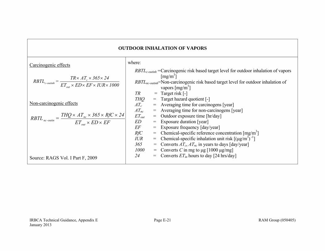
IRBCA Technical Guidance, Appendix E Page E-21 RAM Group (050405) January 2013
OUTDOOR INHALATION OF VAPORS
Carcinogenic effects
1000IUR EF EDET24365 ATTR
= RBTLout
coutinh-c
Non-carcinogenic effects
EF EDET24RfC 365 ATTHQ = RBTL
out
ncoutin-nc
Source: RAGS Vol. I Part F, 2009
where:
RBTLc-outinh = Carcinogenic risk based target level for outdoor inhalation of vapors [mg/m3]
RBTLnc-outinh=Non-carcinogenic risk based target level for outdoor inhalation of vapors [mg/m3]
TR = Target risk [-] THQ = Target hazard quotient [-] ATc = Averaging time for carcinogens [year] ATnc = Averaging time for non-carcinogens [year] ETout = Outdoor exposure time [hr/day] ED = Exposure duration [year] EF = Exposure frequency [day/year] RfC = Chemical-specific reference concentration [mg/m3] IUR = Chemical-specific inhalation unit risk [(μg/m3) -1] 365 = Converts ATc, ATnc in years to days [day/year] 1000 = Converts C in mg to μg [1000 μg/mg] 24 = Converts ETin hours to day [24 hrs/day]
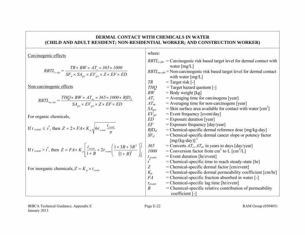
IRBCA Technical Guidance, Appendix E Page E-22 RAM Group (050405) January 2013
DERMAL CONTACT WITH CHEMICALS IN WATER (CHILD AND ADULT RESIDENT; NON-RESIDENTIAL WORKER; AND CONSTRUCTION WORKER)
Carcinogenic effects
EDEFZEVSASF1000365 AT BWTR
= RBTLgwgwd
cdw-c
Non-carcinogenic effects
EDEF Z EVSARfD1000 365 AT BWTHQ
=RBTLgwgw
dncdw-nc
For organic chemicals,
If t event t*, then
eventeventp
tKFAZ 62
If t event > t*, then
2
2
1
3312
1 BBB
Bt
KFAZ eventevent
p
For inorganic chemicals, eventp tKZ
where:
RBTLc-dw = Carcinogenic risk based target level for dermal contact with water [mg/L]
RBTLnc-dw = Non-carcinogenic risk based target level for dermal contact with water [mg/L]
TR = Target risk [-] THQ = Target hazard quotient [-] BW = Body weight [kg] ATc = Averaging time for carcinogens [year] ATnc = Averaging time for non-carcinogens [year] SAgw = Skin surface area available for contact with water [cm2] EVgw = Event frequency [event/day] ED = Exposure duration [year] EF = Exposure frequency [day/year] RfDd = Chemical-specific dermal reference dose [mg/kg-day] SFd = Chemical-specific dermal cancer slope or potency factor
[mg/(kg-day)]-1
365 = Converts ATc, ATnc in years to days [day/year] 1000 = Conversion factor from cm3 to L [cm3/L] t event = Event duration [hr/event] t* = Chemical-specific time to reach steady-state [hr] Z = Chemical-specific dermal factor [cm/event] Kp = Chemical-specific dermal permeability coefficient [cm/hr] FA = Chemical-specific fraction absorbed in water [-] τevent = Chemical-specific lag time [hr/event] B = Chemical-specific relative contribution of permeability
coefficient [-]
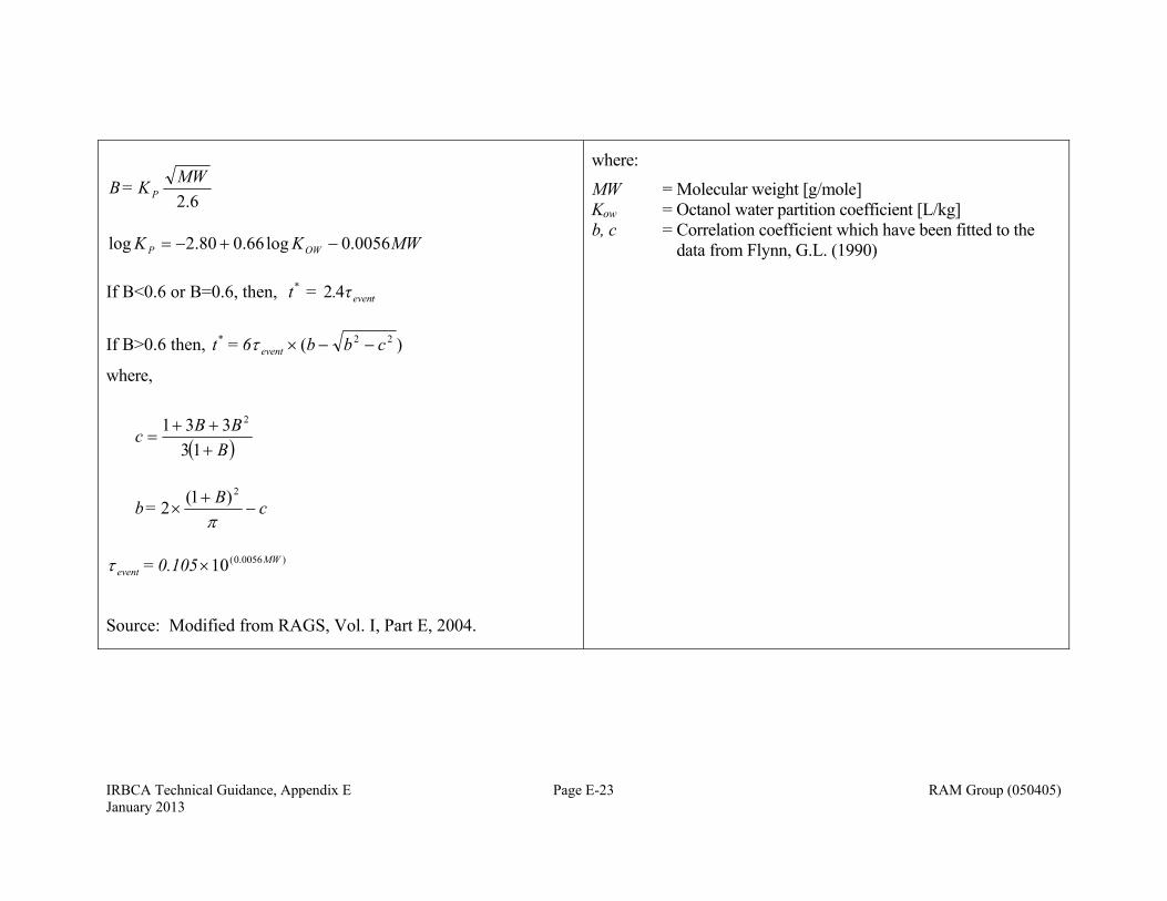
IRBCA Technical Guidance, Appendix E Page E-23 RAM Group (050405) January 2013
6.2
MWK = B P
MWKK OWP 0056.0log66.080.2log
If B<0.6 or B=0.6, then, teven
* τ. = t 42
If B>0.6 then, )( 22 cbb6 = t event*
where,
BBBc
13
331 2
cB = b
2)1(2
)0056.0(10 MW
event 0.105 =
Source: Modified from RAGS, Vol. I, Part E, 2004.
where:
MW = Molecular weight [g/mole] Kow = Octanol water partition coefficient [L/kg] b, c = Correlation coefficient which have been fitted to the
data from Flynn, G.L. (1990)
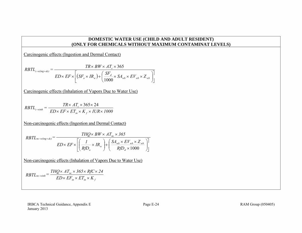
IRBCA Technical Guidance, Appendix E Page E-24 RAM Group (050405) January 2013
DOMESTIC WATER USE (CHILD AND ADULT RESIDENT)
(ONLY FOR CHEMICALS WITHOUT MAXIMUM CONTAMINAT LEVELS)
Carcinogenic effects (Ingestion and Dermal Contact)
wbwbwbd
wo
cdc)w(ing-c
ZEVSASF
IRSFEFED
ATWBTR =RBTL
1000
365
Carcinogenic effects (Inhalation of Vapors Due to Water Use)
1000IURKETEFED TATR
=RBTLfin
cwinh-c
24365
Non-carcinogenic effects (Ingestion and Dermal Contact)
RfD
ZEVSAIR
RfD1EFED
365ATWBTHQ =RBTL
d
wbwbwbw
o
ncdc)w(ing-nc
1000
Non-carcinogenic effects (Inhalation of Vapors Due to Water Use)
KETEFED24RfC365TATHQ
=RBTL finin
ncwinh-nc
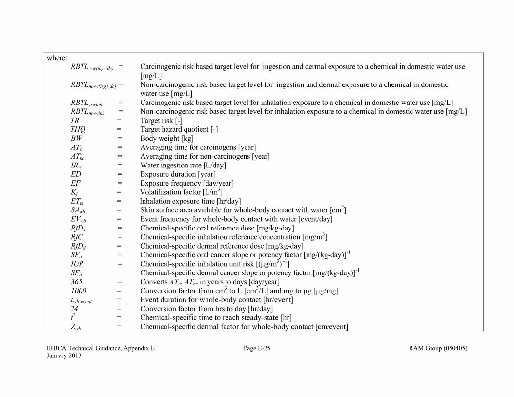
IRBCA Technical Guidance, Appendix E Page E-25 RAM Group (050405) January 2013
where: RBTLc-w(ing+dc) = Carcinogenic risk based target level for ingestion and dermal exposure to a chemical in domestic water use
[mg/L] RBTLnc-w(ing+dc) = Non-carcinogenic risk based target level for ingestion and dermal exposure to a chemical in domestic
water use [mg/L] RBTLc-winh = Carcinogenic risk based target level for inhalation exposure to a chemical in domestic water use [mg/L] RBTLnc-winh = Non-carcinogenic risk based target level for inhalation exposure to a chemical in domestic water use [mg/L] TR = Target risk [-] THQ = Target hazard quotient [-] BW = Body weight [kg] ATc = Averaging time for carcinogens [year] ATnc = Averaging time for non-carcinogens [year] IRw = Water ingestion rate [L/day] ED = Exposure duration [year] EF = Exposure frequency [day/year] Kf = Volatilization factor [L/m3] ETin = Inhalation exposure time [hr/day] SAwb = Skin surface area available for whole-body contact with water [cm2] EVwb = Event frequency for whole-body contact with water [event/day] RfDo = Chemical-specific oral reference dose [mg/kg-day] RfC = Chemical-specific inhalation reference concentration [mg/m3] RfDd = Chemical-specific dermal reference dose [mg/kg-day] SFo = Chemical-specific oral cancer slope or potency factor [mg/(kg-day)]-1 IUR = Chemical-specific inhalation unit risk [(μg/m3) -1] SFd = Chemical-specific dermal cancer slope or potency factor [mg/(kg-day)]-1
365 = Converts ATc, ATnc in years to days [day/year] 1000 = Conversion factor from cm3 to L [cm3/L] and mg to μg [μg/mg] twb-event = Event duration for whole-body contact [hr/event] 24 = Conversion factor from hrs to day [hr/day] t* = Chemical-specific time to reach steady-state [hr] Zwb = Chemical-specific dermal factor for whole-body contact [cm/event]
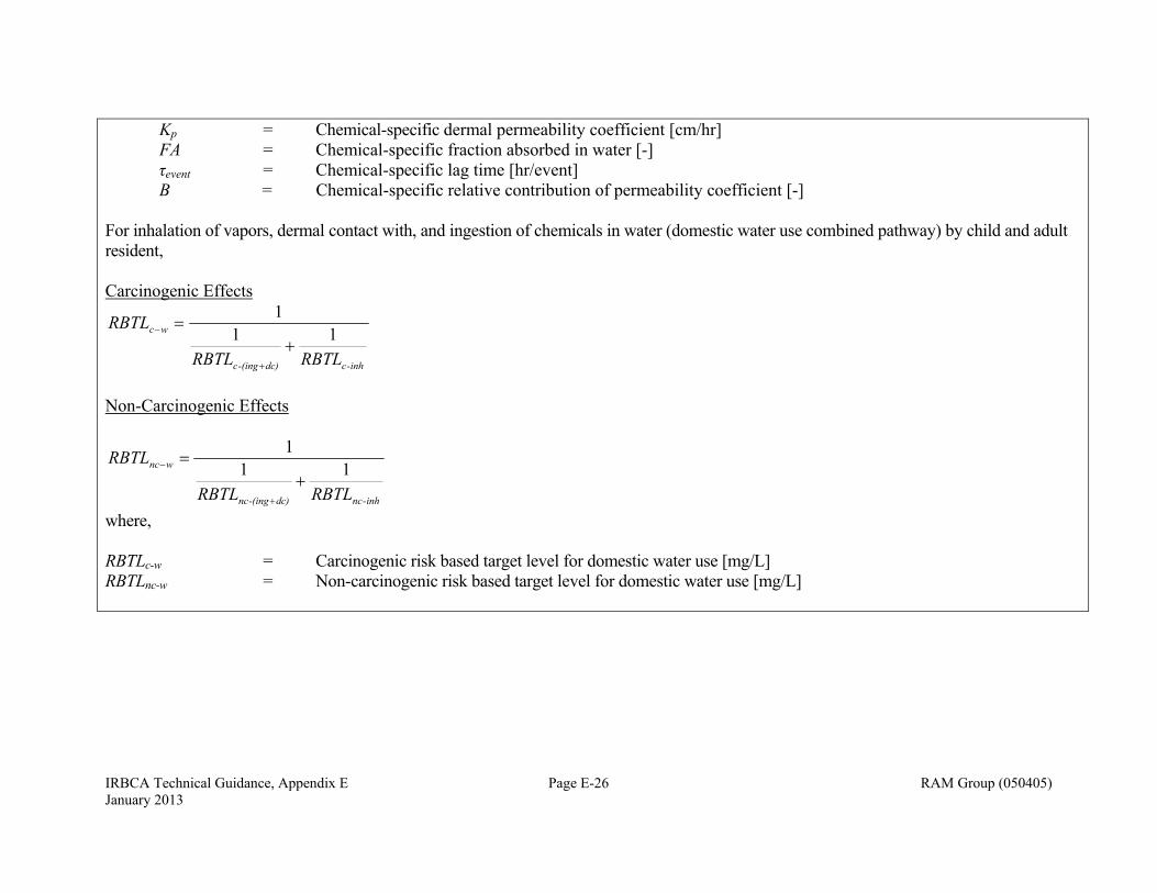
IRBCA Technical Guidance, Appendix E Page E-26 RAM Group (050405) January 2013
Kp = Chemical-specific dermal permeability coefficient [cm/hr] FA = Chemical-specific fraction absorbed in water [-] τevent = Chemical-specific lag time [hr/event] B = Chemical-specific relative contribution of permeability coefficient [-] For inhalation of vapors, dermal contact with, and ingestion of chemicals in water (domestic water use combined pathway) by child and adult resident, Carcinogenic Effects
inh-cdc)-(ingc
wc
RBTLRBTL
RBTL11
1
Non-Carcinogenic Effects
inh-ncdc)-(ingnc
wnc
RBTLRBTL
RBTL11
1
where, RBTLc-w = Carcinogenic risk based target level for domestic water use [mg/L] RBTLnc-w = Non-carcinogenic risk based target level for domestic water use [mg/L]
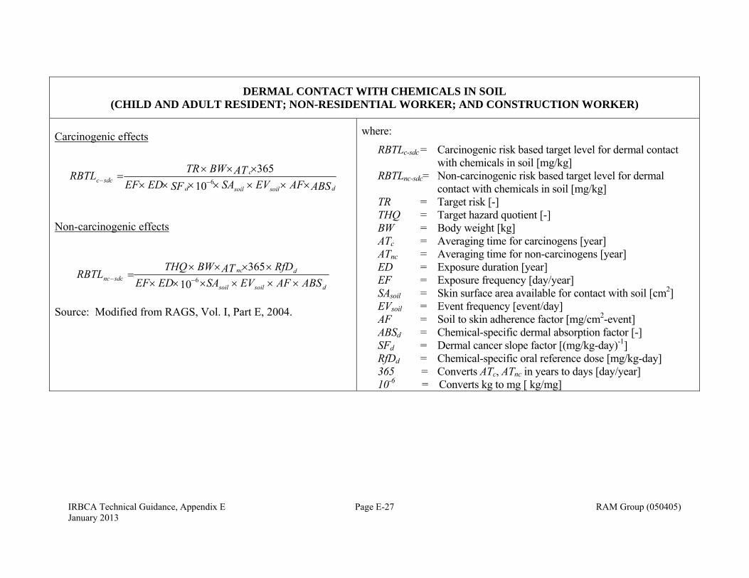
IRBCA Technical Guidance, Appendix E Page E-27 RAM Group (050405) January 2013
DERMAL CONTACT WITH CHEMICALS IN SOIL (CHILD AND ADULT RESIDENT; NON-RESIDENTIAL WORKER; AND CONSTRUCTION WORKER)
Carcinogenic effects
ABSAFEVSASFEDEFATBWTRRBTL
dsoilsoild
csdcc
10
3656
Non-carcinogenic effects
dsoilsoil
dncsdcnc ABSAFEVSAEDEF
RfDATBWTHQRBTL
10
3656
Source: Modified from RAGS, Vol. I, Part E, 2004.
where:
RBTLc-sdc = Carcinogenic risk based target level for dermal contact with chemicals in soil [mg/kg]
RBTLnc-sdc= Non-carcinogenic risk based target level for dermal contact with chemicals in soil [mg/kg]
TR = Target risk [-] THQ = Target hazard quotient [-] BW = Body weight [kg] ATc = Averaging time for carcinogens [year] ATnc = Averaging time for non-carcinogens [year] ED = Exposure duration [year] EF = Exposure frequency [day/year] SAsoil = Skin surface area available for contact with soil [cm2] EVsoil = Event frequency [event/day] AF = Soil to skin adherence factor [mg/cm2-event] ABSd = Chemical-specific dermal absorption factor [-] SFd = Dermal cancer slope factor [(mg/kg-day)-1] RfDd = Chemical-specific oral reference dose [mg/kg-day] 365 = Converts ATc, ATnc in years to days [day/year] 10-6 = Converts kg to mg [ kg/mg]
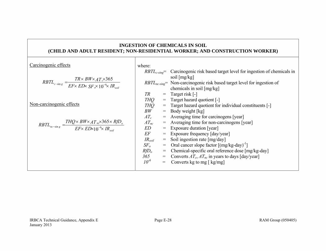
IRBCA Technical Guidance, Appendix E Page E-28 RAM Group (050405) January 2013
INGESTION OF CHEMICALS IN SOIL (CHILD AND ADULT RESIDENT; NON-RESIDENTIAL WORKER; AND CONSTRUCTION WORKER)
Carcinogenic effects
soilo
cgc IRSFEDEF
ATBWTRRBTL
10
3656sin
Non-carcinogenic effects
soil
oncgnc IREDEF
RfDATBWTHQRBTL
10
3656sin
where: RBTLc-sing= Carcinogenic risk based target level for ingestion of chemicals in
soil [mg/kg] RBTLnc-sing= Non-carcinogenic risk based target level for ingestion of
chemicals in soil [mg/kg] TR = Target risk [-] THQ = Target hazard quotient [-] THQ = Target hazard quotient for individual constituents [-] BW = Body weight [kg] ATc = Averaging time for carcinogens [year] ATnc = Averaging time for non-carcinogens [year] ED = Exposure duration [year] EF = Exposure frequency [day/year] IRsoil = Soil ingestion rate [mg/day] SFo = Oral cancer slope factor [(mg/kg-day)-1]
RfDo = Chemical-specific oral reference dose [mg/kg-day] 365 = Converts ATc, ATnc in years to days [day/year] 10-6 = Converts kg to mg [ kg/mg]
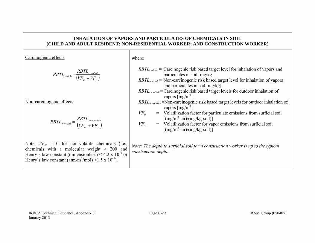
IRBCA Technical Guidance, Appendix E Page E-29 RAM Group (050405) January 2013
INHALATION OF VAPORS AND PARTICULATES OF CHEMICALS IN SOIL (CHILD AND ADULT RESIDENT; NON-RESIDENTIAL WORKER; AND CONSTRUCTION WORKER)
Carcinogenic effects
pss
outinhcc VFVF
RBTLRBTL
sinh
Non-carcinogenic effects
pss
outinhncnc VFVF
RBTLRBTL
sinh
Note: VFss = 0 for non-volatile chemicals (i.e., chemicals with a molecular weight > 200 and Henry’s law constant (dimensionless) < 4.2 x 10⁻⁴ or Henry’s law constant (atm-m3/mol) <1.5 x 10⁻⁵).
where: RBTLc-sinh = Carcinogenic risk based target level for inhalation of vapors and
particulates in soil [mg/kg] RBTLnc-sinh = Non-carcinogenic risk based target level for inhalation of vapors
and particulates in soil [mg/kg] RBTLc-outinh = Carcinogenic risk based target levels for outdoor inhalation of
vapors [mg/m3] RBTLnc-outinh =Non-carcinogenic risk based target levels for outdoor inhalation of
vapors [mg/m3] VFp = Volatilization factor for particulate emissions from surficial soil
[(mg/m3-air)/(mg/kg-soil)] VFss = Volatilization factor for vapor emissions from surficial soil
[(mg/m3-air)/(mg/kg-soil)] Note: The depth to surficial soil for a construction worker is up to the typical construction depth.
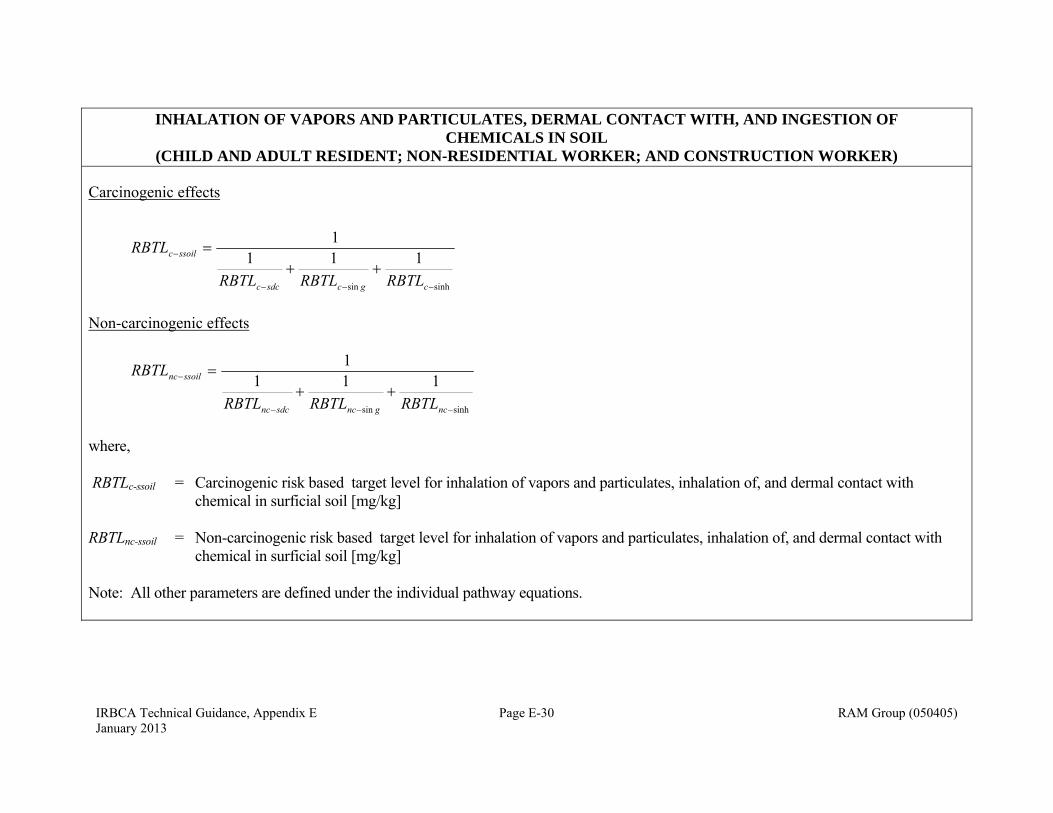
IRBCA Technical Guidance, Appendix E Page E-30 RAM Group (050405) January 2013
INHALATION OF VAPORS AND PARTICULATES, DERMAL CONTACT WITH, AND INGESTION OF CHEMICALS IN SOIL
(CHILD AND ADULT RESIDENT; NON-RESIDENTIAL WORKER; AND CONSTRUCTION WORKER)
Carcinogenic effects
sinhsin
1111
cgcsdcc
ssoilc
RBTLRBTLRBTL
RBTL
Non-carcinogenic effects
sinhsin
1111
ncgncsdcnc
ssoilnc
RBTLRBTLRBTL
RBTL
where, RBTLc-ssoil = Carcinogenic risk based target level for inhalation of vapors and particulates, inhalation of, and dermal contact with
chemical in surficial soil [mg/kg] RBTLnc-ssoil = Non-carcinogenic risk based target level for inhalation of vapors and particulates, inhalation of, and dermal contact with
chemical in surficial soil [mg/kg] Note: All other parameters are defined under the individual pathway equations.
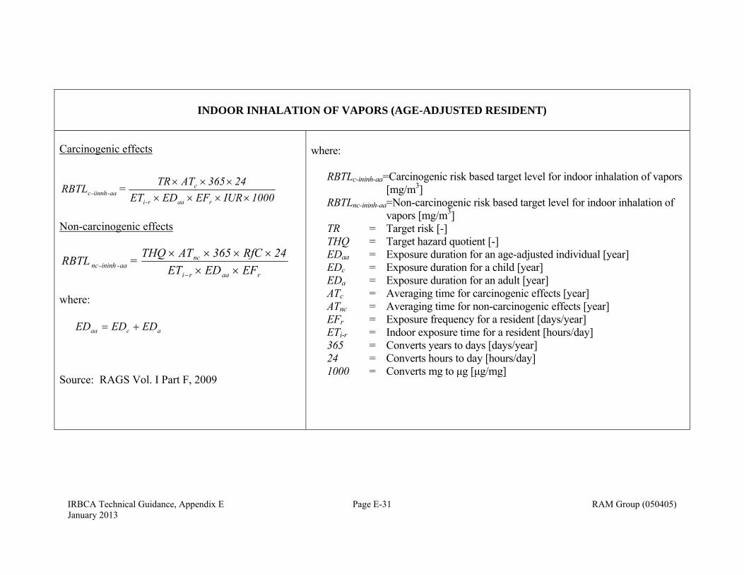
IRBCA Technical Guidance, Appendix E Page E-31 RAM Group (050405) January 2013
INDOOR INHALATION OF VAPORS (AGE-ADJUSTED RESIDENT)
Carcinogenic effects
1000IUR EF EDET24365 ATTR
= RBTLraar-i
caa-iinnh-c
Non-carcinogenic effects
raari
ncaa-ininh-nc EF EDET
24RfC 365 ATTHQ = RBTL
where: acaa EDEDED
Source: RAGS Vol. I Part F, 2009
where: RBTLc-ininh-aa=Carcinogenic risk based target level for indoor inhalation of vapors
[mg/m3] RBTLnc-ininh-aa=Non-carcinogenic risk based target level for indoor inhalation of
vapors [mg/m3] TR = Target risk [-] THQ = Target hazard quotient [-] EDaa = Exposure duration for an age-adjusted individual [year] EDc = Exposure duration for a child [year] EDa = Exposure duration for an adult [year] ATc = Averaging time for carcinogenic effects [year] ATnc = Averaging time for non-carcinogenic effects [year] EFr = Exposure frequency for a resident [days/year] ETi-r = Indoor exposure time for a resident [hours/day] 365 = Converts years to days [days/year] 24 = Converts hours to day [hours/day] 1000 = Converts mg to μg [μg/mg]
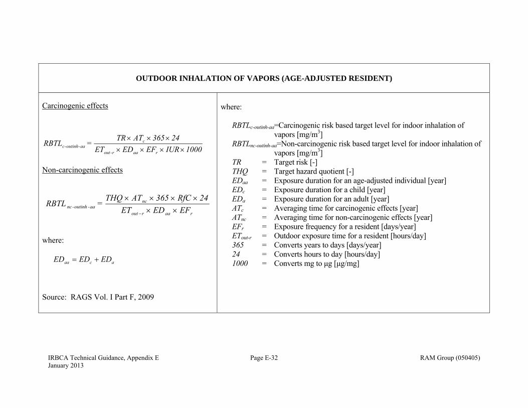
IRBCA Technical Guidance, Appendix E Page E-32 RAM Group (050405) January 2013
OUTDOOR INHALATION OF VAPORS (AGE-ADJUSTED RESIDENT)
Carcinogenic effects
1000IUR EF EDET24365 ATTR
= RBTLraar-out
caa-outinh-c
Non-carcinogenic effects
raarout
ncaa-outinh-nc EF EDET
24RfC 365 ATTHQ = RBTL
where: acaa EDEDED
Source: RAGS Vol. I Part F, 2009
where: RBTLc-outinh-aa=Carcinogenic risk based target level for indoor inhalation of
vapors [mg/m3] RBTLnc-outinh-aa=Non-carcinogenic risk based target level for indoor inhalation of
vapors [mg/m3] TR = Target risk [-] THQ = Target hazard quotient [-] EDaa = Exposure duration for an age-adjusted individual [year] EDc = Exposure duration for a child [year] EDa = Exposure duration for an adult [year] ATc = Averaging time for carcinogenic effects [year] ATnc = Averaging time for non-carcinogenic effects [year] EFr = Exposure frequency for a resident [days/year] ETout-r = Outdoor exposure time for a resident [hours/day] 365 = Converts years to days [days/year] 24 = Converts hours to day [hours/day] 1000 = Converts mg to μg [μg/mg]
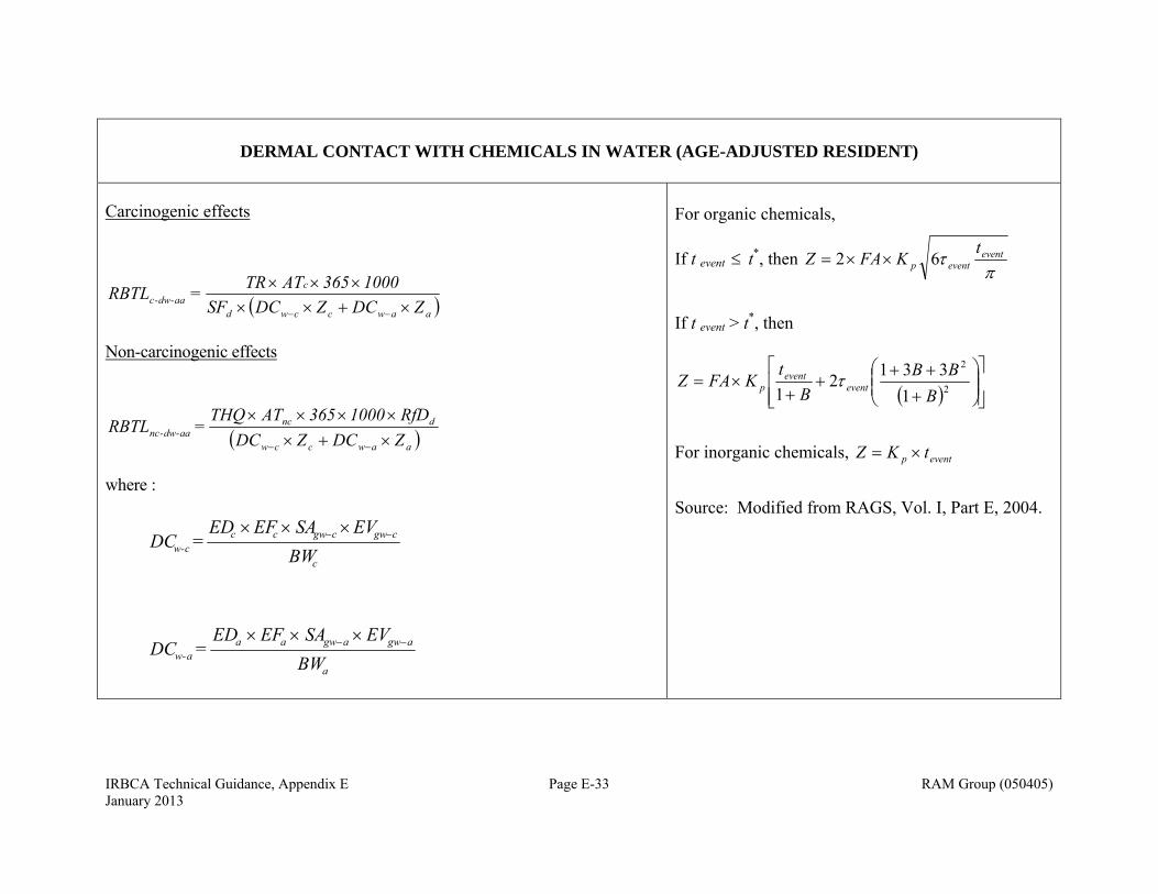
IRBCA Technical Guidance, Appendix E Page E-33 RAM Group (050405) January 2013
DERMAL CONTACT WITH CHEMICALS IN WATER (AGE-ADJUSTED RESIDENT)
Carcinogenic effects
aawccwd
caa-dw-c ZDCZDCSF
1000365 ATTR =RBTL
Non-carcinogenic effects
aawccw
dncaa-dw-nc ZDCZDC
RfD1000 365ATTHQ = RBTL
where :
c
cgwcgwccc-w BW
EVSAEFED = DC
a
agwagwaaa-w BW
EVSAEFED = DC
For organic chemicals,
If t event t*, then
eventeventp
tKFAZ 62
If t event > t*, then
2
2
1
3312
1 BBB
Bt
KFAZ eventevent
p
For inorganic chemicals, eventp tKZ
Source: Modified from RAGS, Vol. I, Part E, 2004.
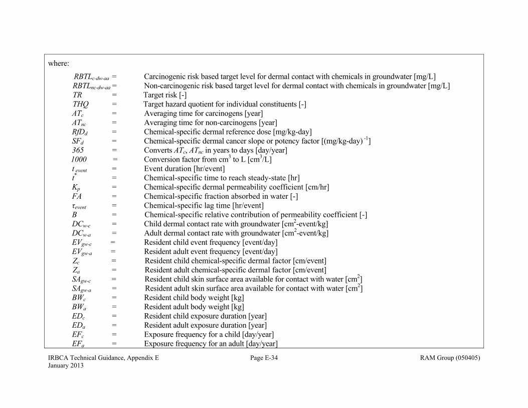
IRBCA Technical Guidance, Appendix E Page E-34 RAM Group (050405) January 2013
where:
RBTLc-dw-aa = Carcinogenic risk based target level for dermal contact with chemicals in groundwater [mg/L] RBTLnc-dw-aa = Non-carcinogenic risk based target level for dermal contact with chemicals in groundwater [mg/L] TR = Target risk [-] THQ = Target hazard quotient for individual constituents [-] ATc = Averaging time for carcinogens [year] ATnc = Averaging time for non-carcinogens [year] RfDd = Chemical-specific dermal reference dose [mg/kg-day] SFd = Chemical-specific dermal cancer slope or potency factor [(mg/kg-day) -1]
365 = Converts ATc, ATnc in years to days [day/year] 1000 = Conversion factor from cm3 to L [cm3/L]
t event = Event duration [hr/event] t* = Chemical-specific time to reach steady-state [hr] Kp = Chemical-specific dermal permeability coefficient [cm/hr] FA = Chemical-specific fraction absorbed in water [-] τevent = Chemical-specific lag time [hr/event] B = Chemical-specific relative contribution of permeability coefficient [-]
DCw-c = Child dermal contact rate with groundwater [cm2-event/kg] DCw-a = Adult dermal contact rate with groundwater [cm2-event/kg]
EVgw-c = Resident child event frequency [event/day] EVgw-a = Resident adult event frequency [event/day]
Zc = Resident child chemical-specific dermal factor [cm/event] Za = Resident adult chemical-specific dermal factor [cm/event]
SAgw-c = Resident child skin surface area available for contact with water [cm2] SAgw-a = Resident adult skin surface area available for contact with water [cm2]
BWc = Resident child body weight [kg] BWa = Resident adult body weight [kg] EDc = Resident child exposure duration [year] EDa = Resident adult exposure duration [year] EFc = Exposure frequency for a child [day/year] EFa = Exposure frequency for an adult [day/year]

IRBCA Technical Guidance, Appendix E Page E-35 RAM Group (050405) January 2013
DOMESTIC WATER USE (AGE-ADJUSTED RESIDENT)
(ONLY FOR CHEMICALS WITHOUT MAXIMUM CONTAMINAT LEVELS)
Carcinogenic effects (Ingestion and Dermal Contact)
awbawbcwbcwbd
aawo
cdc)-(ingc
ZDCZDCSF
IRSF
ATTR = RBTL
1000
365
Carcinogenic effects (Inhalation of Water Vapors)
1000KETEFEDIUR ATTR
= RBTLfa-inaaa
cinh-c
24365
Non-carcinogenic effects(Ingestion and Dermal Contact)
1000
365
d
awbawbcwbcwbaaw
o
ncdc)-(ingnc
RfDZDCZDC
IRRfD
1ATTHQ
= RBTL
Non-carcinogenic effects(Inhalation of Water Vapors)
fa-inaaa
ncinh-nc KETEFEDC
RfCATTHQ =RBTL
24365
where: acaa EDDE = ED
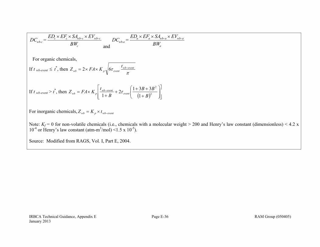
IRBCA Technical Guidance, Appendix E Page E-36 RAM Group (050405) January 2013
c
cwbcwbccc-wb BW
EVSAEFED = DC
and a
awbawbaaa-wb BW
EVSAEFED = DC
For organic chemicals,
If t wb-event t*, then
eventwbeventpwb
tKFAZ 62
If t wb-event > t*, then
2
2
1
3312
1 BBB
Bt
KFAZ eventeventwb
pwb
For inorganic chemicals, eventwbpwb tKZ
Note: Kf = 0 for non-volatile chemicals (i.e., chemicals with a molecular weight > 200 and Henry’s law constant (dimensionless) < 4.2 x 10⁻⁴ or Henry’s law constant (atm-m3/mol) <1.5 x 10⁻⁵). Source: Modified from RAGS, Vol. I, Part E, 2004.
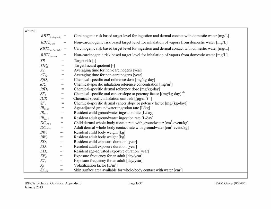
IRBCA Technical Guidance, Appendix E Page E-37 RAM Group (050405) January 2013
where: dc)-(ingcRBTL = Carcinogenic risk based target level for ingestion and dermal contact with domestic water [mg/L]
inh-cRBTL = Non-carcinogenic risk based target level for inhalation of vapors from domestic water [mg/L]
dc)-(ingncRBTL = Carcinogenic risk based target level for ingestion and dermal contact with domestic water [mg/L]
inh-ncRBTL = Non-carcinogenic risk based target level for inhalation of vapors from domestic water [mg/L]
TR = Target risk [-] THQ = Target hazard quotient [-] ATc = Averaging time for non-carcinogens [year] ATnc = Averaging time for non-carcinogens [year] RfDo = Chemical-specific oral reference dose [mg/kg-day] RfC = Chemical-specific inhalation reference concentration [mg/m3] RfDd = Chemical-specific dermal reference dose [mg/kg-day] SFo = Chemical-specific oral cancer slope or potency factor [(mg/kg-day) -1]
IUR = Chemical-specific inhalation unit risk [(μg/m3) -1] SFd = Chemical-specific dermal cancer slope or potency factor [mg/(kg-day)]-1 IRw-aa = Age-adjusted groundwater ingestion rate [L/kg] IRw-c = Resident child groundwater ingestion rate [L/day] IRw- a = Resident adult groundwater ingestion rate [L/day] DCwb-c = Child dermal whole-body contact rate with groundwater [cm2-event/kg] DCwb-a = Adult dermal whole-body contact rate with groundwater [cm2-event/kg] BWc = Resident child body weight [kg] BWa = Resident adult body weight [kg] EDc = Resident child exposure duration [year] EDa = Resident adult exposure duration [year] EDaa = Resident age-adjusted exposure duration [year] EFa = Exposure frequency for an adult [day/year] ETa = Exposure frequency for an adult [day/year] Kf = Volatilization factor [L/m3] SAwb = Skin surface area available for whole-body contact with water [cm2]
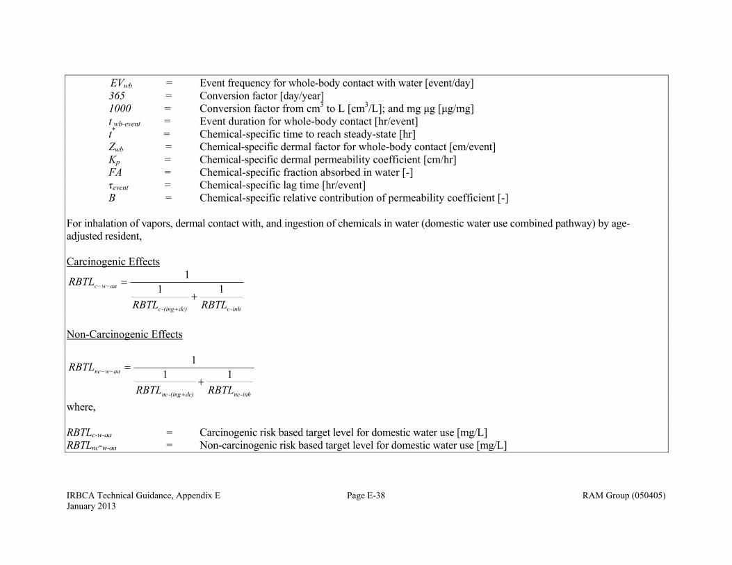
IRBCA Technical Guidance, Appendix E Page E-38 RAM Group (050405) January 2013
EVwb = Event frequency for whole-body contact with water [event/day] 365 = Conversion factor [day/year] 1000 = Conversion factor from cm3 to L [cm3/L]; and mg μg [μg/mg] t wb-event = Event duration for whole-body contact [hr/event] t* = Chemical-specific time to reach steady-state [hr] Zwb = Chemical-specific dermal factor for whole-body contact [cm/event] Kp = Chemical-specific dermal permeability coefficient [cm/hr] FA = Chemical-specific fraction absorbed in water [-] τevent = Chemical-specific lag time [hr/event] B = Chemical-specific relative contribution of permeability coefficient [-] For inhalation of vapors, dermal contact with, and ingestion of chemicals in water (domestic water use combined pathway) by age-adjusted resident, Carcinogenic Effects
inh-cdc)-(ingc
aawc
RBTLRBTL
RBTL11
1
Non-Carcinogenic Effects
inh-ncdc)-(ingnc
aawnc
RBTLRBTL
RBTL11
1
where, RBTLc-w-aa = Carcinogenic risk based target level for domestic water use [mg/L] RBTLnc-w-aa = Non-carcinogenic risk based target level for domestic water use [mg/L]
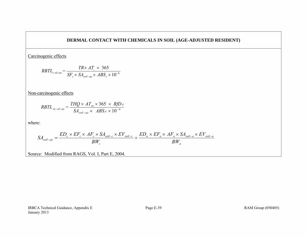
IRBCA Technical Guidance, Appendix E Page E-39 RAM Group (050405) January 2013
DERMAL CONTACT WITH CHEMICALS IN SOIL (AGE-ADJUSTED RESIDENT)
Carcinogenic effects
610
365
dd
c
ABSSASF ATTR
= BTLRaasoil
aa-sd-c
Non-carcinogenic effects
610
365
daasoil
dncaa-sd-nc ABSSA
RfD ATTHQ = RBTL
where:
a
asoilasoilaaa
c
csoilcsoilcccaasoil BW
EVSAAFEFEDBW
EVSAAFEFEDSA
Source: Modified from RAGS, Vol. I, Part E, 2004.
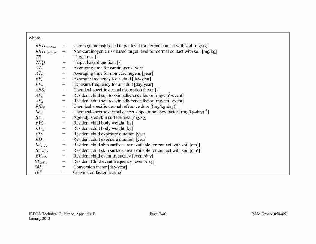
IRBCA Technical Guidance, Appendix E Page E-40 RAM Group (050405) January 2013
where:
RBTLc-sd-aa = Carcinogenic risk based target level for dermal contact with soil [mg/kg] RBTLnc-sd-aa = Non-carcinogenic risk based target level for dermal contact with soil [mg/kg] TR = Target risk [-] THQ = Target hazard quotient [-] ATc = Averaging time for carcinogens [year] ATnc = Averaging time for non-carcinogens [year] EFc = Exposure frequency for a child [day/year] EFa = Exposure frequency for an adult [day/year] ABSd = Chemical-specific dermal absorption factor [-] AFc = Resident child soil to skin adherence factor [mg/cm2-event] AFa = Resident adult soil to skin adherence factor [mg/cm2-event]
RfDd = Chemical-specific dermal reference dose [(mg/kg-day)] SFd = Chemical-specific dermal cancer slope or potency factor [(mg/kg-day) -1] SAaa = Age-adjusted skin surface area [mg/kg] BWc = Resident child body weight [kg] BWa = Resident adult body weight [kg] EDc = Resident child exposure duration [year] EDa = Resident adult exposure duration [year] SAsoil-c = Resident child skin surface area available for contact with soil [cm2] SAsoil-a = Resident adult skin surface area available for contact with soil [cm2] EVsoil-c = Resident child event frequency [event/day] EVsoil-a = Resident Child event frequency [event/day] 365 = Conversion factor [day/year] 10-6 = Conversion factor [kg/mg]
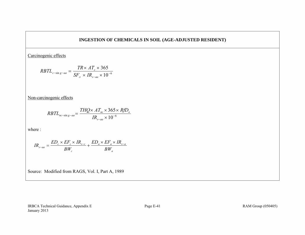
IRBCA Technical Guidance, Appendix E Page E-41 RAM Group (050405) January 2013
INGESTION OF CHEMICALS IN SOIL (AGE-ADJUSTED RESIDENT)
Carcinogenic effects
6sin 10
365
aas
caagc IRSF
ATTRRBTLO
Non-carcinogenic effects
6sin 10
365
aas
oncaagnc IR
RfDATTHQRBTL
where :
a
asaa
c
csccaas BW
IREFEDBW
IREFEDIR
Source: Modified from RAGS, Vol. I, Part A, 1989
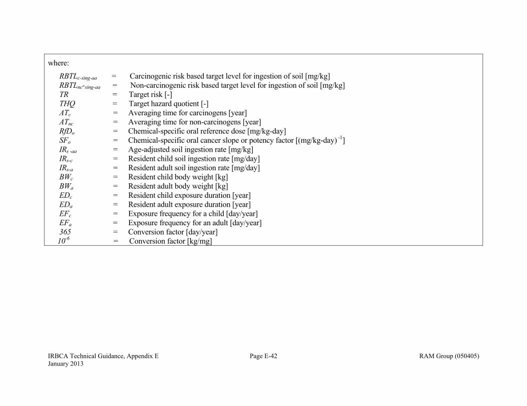
IRBCA Technical Guidance, Appendix E Page E-42 RAM Group (050405) January 2013
where:
RBTLc-sing-aa = Carcinogenic risk based target level for ingestion of soil [mg/kg] RBTLnc-sing-aa = Non-carcinogenic risk based target level for ingestion of soil [mg/kg] TR = Target risk [-] THQ = Target hazard quotient [-] ATc = Averaging time for carcinogens [year] ATnc = Averaging time for non-carcinogens [year]
RfDo = Chemical-specific oral reference dose [mg/kg-day] SFo = Chemical-specific oral cancer slope or potency factor [(mg/kg-day) -1] IRs -aa = Age-adjusted soil ingestion rate [mg/kg] IRs-c = Resident child soil ingestion rate [mg/day] IRs-a = Resident adult soil ingestion rate [mg/day] BWc = Resident child body weight [kg] BWa = Resident adult body weight [kg] EDc = Resident child exposure duration [year] EDa = Resident adult exposure duration [year]
EFc = Exposure frequency for a child [day/year] EFa = Exposure frequency for an adult [day/year]
365 = Conversion factor [day/year] 10-6 = Conversion factor [kg/mg]
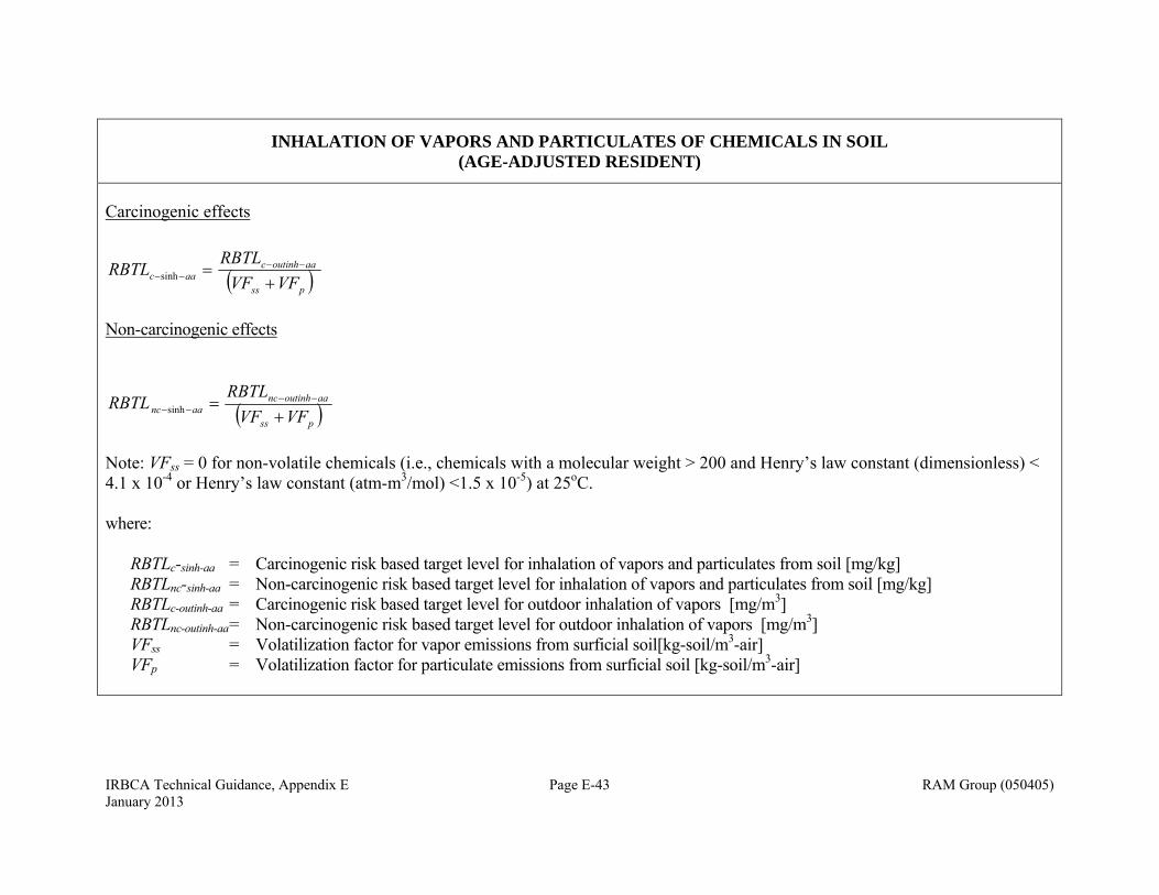
IRBCA Technical Guidance, Appendix E Page E-43 RAM Group (050405) January 2013
INHALATION OF VAPORS AND PARTICULATES OF CHEMICALS IN SOIL (AGE-ADJUSTED RESIDENT)
Carcinogenic effects
pss
aaoutinhcaac VFVF
RBTLRBTL
sinh
Non-carcinogenic effects
pss
aaoutinhncaanc VFVF
RBTLRBTL
sinh
Note: VFss = 0 for non-volatile chemicals (i.e., chemicals with a molecular weight > 200 and Henry’s law constant (dimensionless) < 4.1 x 10⁻⁴ or Henry’s law constant (atm-m3/mol) <1.5 x 10⁻⁵) at 25oC. where: RBTLc-sinh-aa = Carcinogenic risk based target level for inhalation of vapors and particulates from soil [mg/kg] RBTLnc-sinh-aa = Non-carcinogenic risk based target level for inhalation of vapors and particulates from soil [mg/kg] RBTLc-outinh-aa = Carcinogenic risk based target level for outdoor inhalation of vapors [mg/m3] RBTLnc-outinh-aa = Non-carcinogenic risk based target level for outdoor inhalation of vapors [mg/m3] VFss = Volatilization factor for vapor emissions from surficial soil[kg-soil/m3-air]
VFp = Volatilization factor for particulate emissions from surficial soil [kg-soil/m3-air]
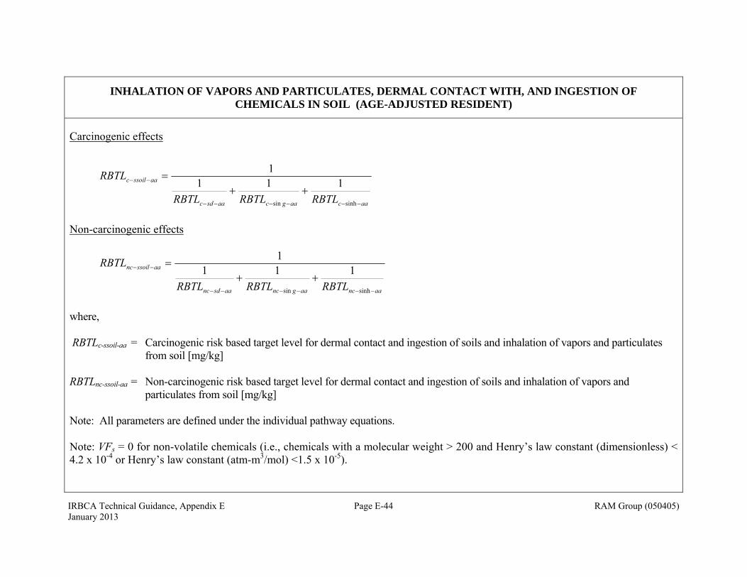
IRBCA Technical Guidance, Appendix E Page E-44 RAM Group (050405) January 2013
INHALATION OF VAPORS AND PARTICULATES, DERMAL CONTACT WITH, AND INGESTION OF CHEMICALS IN SOIL (AGE-ADJUSTED RESIDENT)
Carcinogenic effects
aacaagcaasdc
aassoilc
RBTLRBTLRBTL
RBTL
sinhsin
1111
Non-carcinogenic effects
aancaagncaasdnc
aassoilnc
RBTLRBTLRBTL
RBTL
sinhsin
1111
where, RBTLc-ssoil-aa = Carcinogenic risk based target level for dermal contact and ingestion of soils and inhalation of vapors and particulates
from soil [mg/kg] RBTLnc-ssoil-aa = Non-carcinogenic risk based target level for dermal contact and ingestion of soils and inhalation of vapors and
particulates from soil [mg/kg] Note: All parameters are defined under the individual pathway equations. Note: VFs = 0 for non-volatile chemicals (i.e., chemicals with a molecular weight > 200 and Henry’s law constant (dimensionless) < 4.2 x 10⁻⁴ or Henry’s law constant (atm-m3/mol) <1.5 x 10⁻⁵).
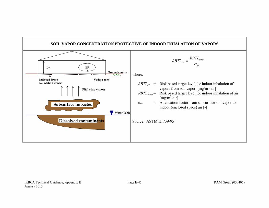
IRBCA Technical Guidance, Appendix E Page E-45 RAM Group (050405) January 2013
SOIL VAPOR CONCENTRATION PROTECTIVE OF INDOOR INHALATION OF VAPORS
sv
ininhsvi
RBTLRBTL
where: RBTLsvi = Risk based target level for indoor inhalation of
vapors from soil vapor [mg/m3-air] RBTLininh = Risk based target level for indoor inhalation of air
[mg/m3-air] αsv = Attenuation factor from subsurface soil vapor to
indoor (enclosed space) air [-] Source: ASTM E1739-95
Ground surface
Vadose zone
Water Table
Enclosed Space Foundation Cracks
Dissolved contaminants
ERLB
Subsurface impacted
Diffusing vapors
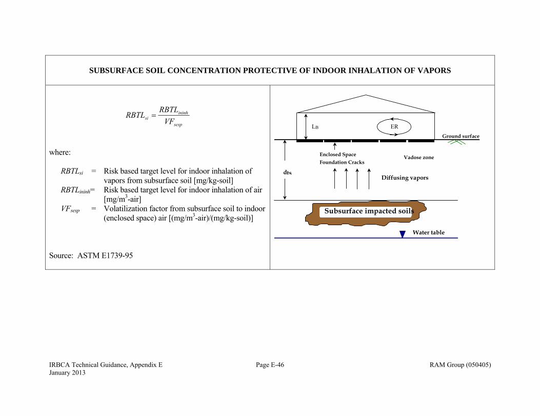
IRBCA Technical Guidance, Appendix E Page E-46 RAM Group (050405) January 2013
SUBSURFACE SOIL CONCENTRATION PROTECTIVE OF INDOOR INHALATION OF VAPORS
sesp
ininhsi VF
RBTLRBTL
where: RBTLsi = Risk based target level for indoor inhalation of
vapors from subsurface soil [mg/kg-soil] RBTLininh= Risk based target level for indoor inhalation of air
[mg/m3-air] VFsesp = Volatilization factor from subsurface soil to indoor
(enclosed space) air [(mg/m3-air)/(mg/kg-soil)] Source: ASTM E1739-95
dts Diffusing vapors
Water table
Subsurface impacted soils
Ground surface
Vadose zone Enclosed Space Foundation Cracks
ER L B
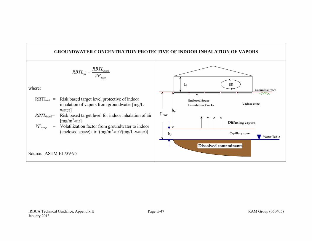
IRBCA Technical Guidance, Appendix E Page E-47 RAM Group (050405) January 2013
GROUNDWATER CONCENTRATION PROTECTIVE OF INDOOR INHALATION OF VAPORS
wesp
ininhwi VF
RBTLRBTL
where: RBTLwi = Risk based target level protective of indoor
inhalation of vapors from groundwater [mg/L-water]
RBTLininh= Risk based target level for indoor inhalation of air [mg/m3-air]
VFwesp = Volatilization factor from groundwater to indoor (enclosed space) air [(mg/m3-air)/(mg/L-water)]
Source: ASTM E1739-95
Ground surface
Capillary zone
hvLGW
Vadose zone
Water Table
Enclosed Space
Dissolved contaminants
Diffusing vapors
hc
Foundation Cracks
ERLB
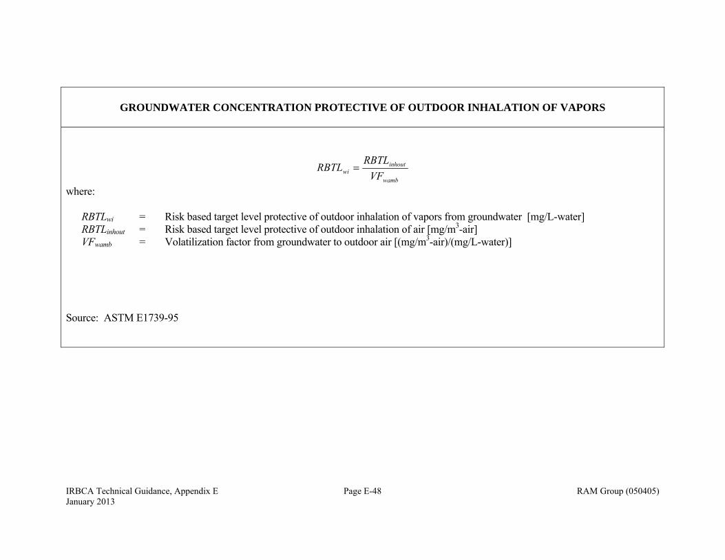
IRBCA Technical Guidance, Appendix E Page E-48 RAM Group (050405) January 2013
GROUNDWATER CONCENTRATION PROTECTIVE OF OUTDOOR INHALATION OF VAPORS
wamb
inhoutwi VF
RBTLRBTL
where: RBTLwi = Risk based target level protective of outdoor inhalation of vapors from groundwater [mg/L-water] RBTLinhout = Risk based target level protective of outdoor inhalation of air [mg/m3-air] VFwamb = Volatilization factor from groundwater to outdoor air [(mg/m3-air)/(mg/L-water)] Source: ASTM E1739-95
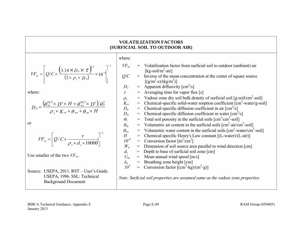
IRBCA Technical Guidance, Appendix E Page E-49 RAM Group (050405) January 2013
VOLATILIZATION FACTORS (SURFICIAL SOIL TO OUTDOOR AIR)
1
4
21
102
14.3
D
DCQVF
As
A
ss
where:
HKDHDD
aswssvs
Tw
wsa
asA
2310310
or
1
10000/
ss
ss dCQVF
Use smaller of the two VFss. Source: USEPA, 2011. RST – User’s Guide. USEPA, 1996. SSL: Technical Background Document
where:
VFss = Volatilization factor from surficial soil to outdoor (ambient) air [kg-soil/m3-air] Q/C = Inverse of the mean concentration at the center of square source [(g/m2-s)/(kg/m3)] DA = Apparent diffusivity [cm2/s] = Averaging time for vapor flux [s] s = Vadose zone dry soil bulk density of surficial soil [g-soil/cm3-soil] Ksv = Chemical-specific solid-water sorption coefficient [cm3-water/g-soil] Da = Chemical-specific diffusion coefficient in air [cm2/s] Dw = Chemical-specific diffusion coefficient in water [cm2/s] T = Total soil porosity in the surficial soils [cm3/cm3-soil] as = Volumetric air content in the surficial soils [cm3-air/cm3-soil] ws = Volumetric water content in the surficial soils [cm3-water/cm3-soil] H = Chemical-specific Henry's Law constant [(L-water)/(L-air)] 10-4 = Conversion factor [m2/cm2] Wa = Dimension of soil source area parallel to wind direction [cm] ds = Depth to base of surficial soil zone [cm] Um = Mean annual wind speed [m/s] δa = Breathing zone height [cm] 103 = Conversion factor [(cm3-kg)/(m3-g)] Note: Surficial soil properties are assumed same as the vadose zone properties.
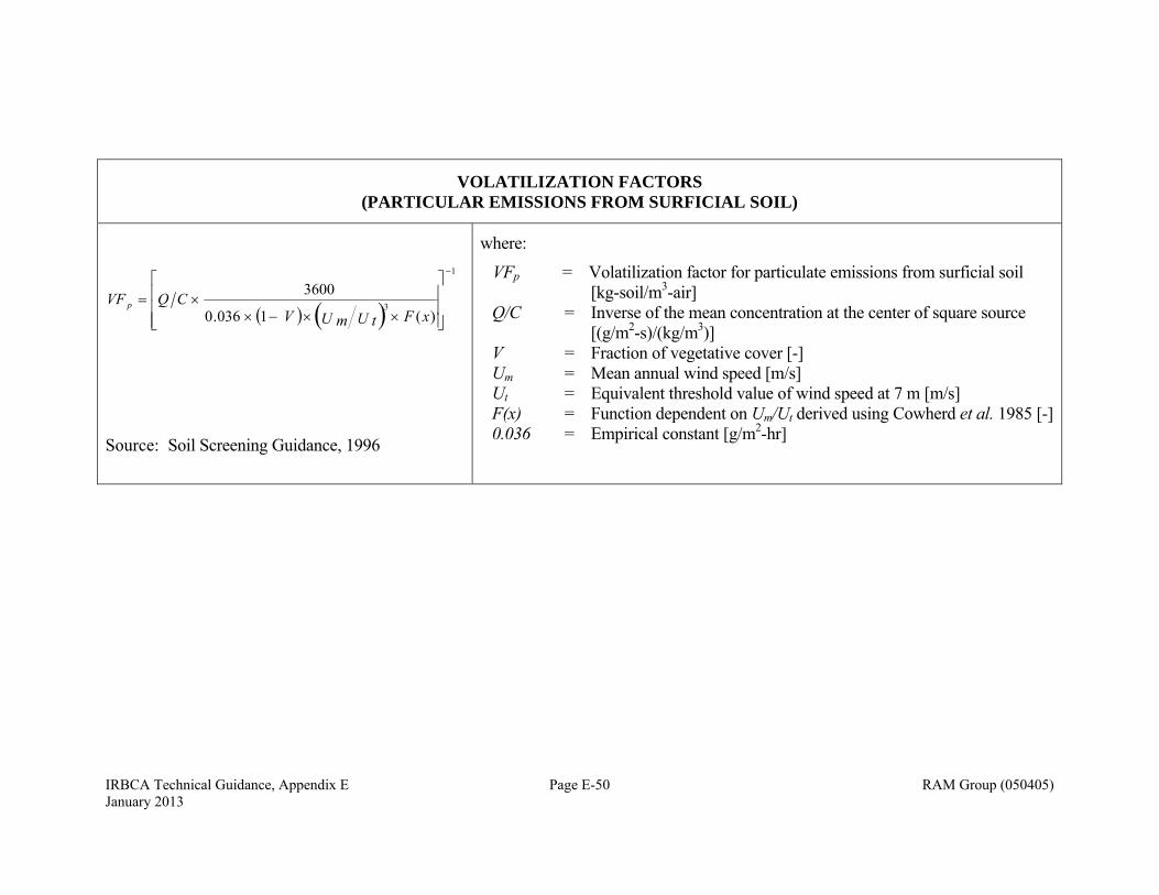
IRBCA Technical Guidance, Appendix E Page E-50 RAM Group (050405) January 2013
VOLATILIZATION FACTORS (PARTICULAR EMISSIONS FROM SURFICIAL SOIL)
1
3)(1036.0
3600
xFU tU mVCQVF p
Source: Soil Screening Guidance, 1996
where:
VFp = Volatilization factor for particulate emissions from surficial soil [kg-soil/m3-air]
Q/C = Inverse of the mean concentration at the center of square source [(g/m2-s)/(kg/m3)]
V = Fraction of vegetative cover [-] Um = Mean annual wind speed [m/s] Ut = Equivalent threshold value of wind speed at 7 m [m/s] F(x) = Function dependent on Um/Ut derived using Cowherd et al. 1985 [-] 0.036 = Empirical constant [g/m2-hr]
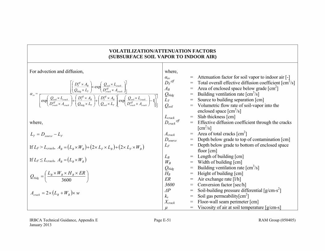
IRBCA Technical Guidance, Appendix E Page E-51 RAM Group (050405) January 2013
VOLATILIZATION/ATTENUATION FACTORS (SUBSURFACE SOIL VAPOR TO INDOOR AIR)
For advection and diffusion,
1expexp
exp
crackeffcrack
cracksoil
Tsoil
BeffT
Tbldg
BeffT
crackeffcrack
cracksoil
crackeffcrack
cracksoil
Tbldg
BeffT
sv
ADLQ
LQAD
LQAD
ADLQ
ADLQ
LQAD
=
where,
FsourceT LDL
If LF > Lcrack, BFBFBBB WLLLWLA 22 If LF ≤ Lcrack, BBB WLA
3600
ERHWLQ BBBbldg
wWLA BBcrack 2
where, αsv = Attenuation factor for soil vapor to indoor air [-] DT
eff = Total overall effective diffusion coefficient [cm2/s] AB = Area of enclosed space below grade [cm2] Qbldg = Building ventilation rate [cm3/s] LT = Source to building separation [cm] Qsoil = Volumetric flow rate of soil-vapor into the
enclosed space [cm3/s] Lcrack = Slab thickness [cm] Dcrack
eff = Effective diffusion coefficient through the cracks [cm2/s]
Acrack = Area of total cracks [cm2] Dsource = Depth below grade to top of contamination [cm] LF = Depth below grade to bottom of enclosed space
floor [cm] LB = Length of building [cm] WB = Width of building [cm] Qbldg = Building ventilation rate [cm3/s] HB = Height of building [cm] ER = Air exchange rate [l/h] 3600 = Conversion factor [sec/h] ΔP = Soil-building pressure differential [g/cm-s2] kv = Soil gas permeability[cm2] Xcrack = Floor-wall seam perimeter [cm] µ = Viscosity of air at soil temperature [g/cm-s]
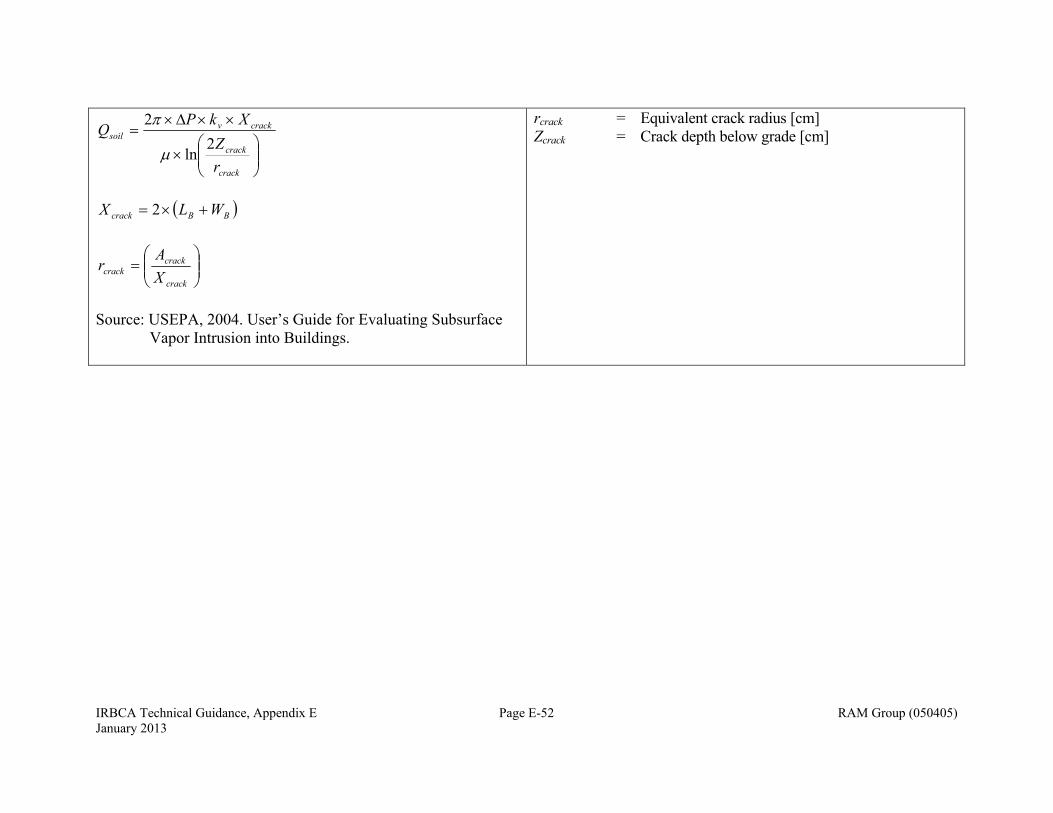
IRBCA Technical Guidance, Appendix E Page E-52 RAM Group (050405) January 2013
crack
crack
crackvsoil
rZ
XkPQ
2ln
2
BBcrack WLX 2
crack
crackcrack X
Ar
Source: USEPA, 2004. User’s Guide for Evaluating Subsurface
Vapor Intrusion into Buildings.
rcrack = Equivalent crack radius [cm] Zcrack = Crack depth below grade [cm]

IRBCA Technical Guidance, Appendix E Page E-53 RAM Group (050405) January 2013
VOLATILIZATION FACTORS (SUBSURACE SOIL TO INDOOR AIR)
10 H + K +
H = VF 3
sasssvws
ssesp
][
Note: αs is calculated using equation for αsv with depth to subsurface soil source. Source: USEPA, 2004. User’s Guide for Evaluating
Subsurface Vapor Intrusion into Buildings.
where, VFsesp = Volatilization factor from subsurface soil to indoor (enclosed
space) air [m3-air/(mg/kg-soil)] H = Chemical-specific Henry's Law constant [L-water/L-air] s = Dry soil bulk density [g-soil/cm3-soil] ws = Volumetric water content in vadose zone soil [cm3-
water/cm3-soil] as = Volumetric air content in vadose zone soil [cm3-air/cm3-soil] Ksv = focv Koc = Chemical-specific soil-water sorption
coefficient in vadose zone [cm3/g] αs = Attenuation factor from subsurface soil to indoor 103 = Conversion factor [(cm3-kg)/(m3-g)]
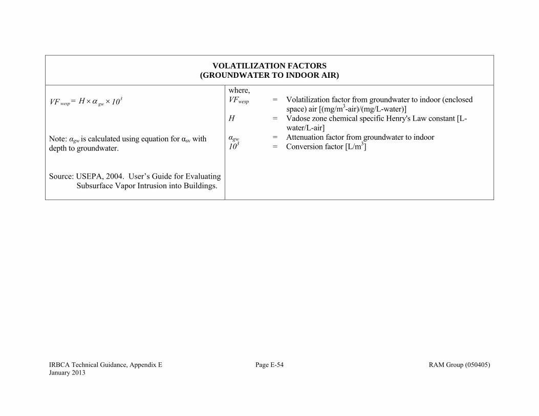
IRBCA Technical Guidance, Appendix E Page E-54 RAM Group (050405) January 2013
VOLATILIZATION FACTORS (GROUNDWATER TO INDOOR AIR)
10 H= VF 3gwwesp
Note: αgw is calculated using equation for αsv with depth to groundwater. Source: USEPA, 2004. User’s Guide for Evaluating
Subsurface Vapor Intrusion into Buildings.
where, VFwesp = Volatilization factor from groundwater to indoor (enclosed
space) air [(mg/m3-air)/(mg/L-water)] H = Vadose zone chemical specific Henry's Law constant [L-
water/L-air] αgw = Attenuation factor from groundwater to indoor 103 = Conversion factor [L/m3]
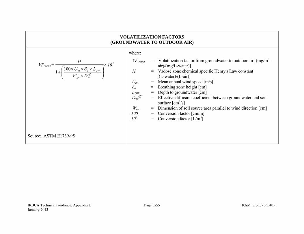
IRBCA Technical Guidance, Appendix E Page E-55 RAM Group (050405) January 2013
VOLATILIZATION FACTORS (GROUNDWATER TO OUTDOOR AIR)
10
DWLU
H = VF 3
effwsga
GWam
wamb
100
1
Source: ASTM E1739-95
where:
VFwamb = Volatilization factor from groundwater to outdoor air [(mg/m3-air)/(mg/L-water)]
H = Vadose zone chemical specific Henry's Law constant [(L-water)/(L-air)] Um = Mean annual wind speed [m/s] δa = Breathing zone height [cm] LGW = Depth to groundwater [cm] Dws
eff = Effective diffusion coefficient between groundwater and soil surface [cm2/s]
Wga = Dimension of soil source area parallel to wind direction [cm] 100 = Conversion factor [cm/m] 103 = Conversion factor [L/m3]
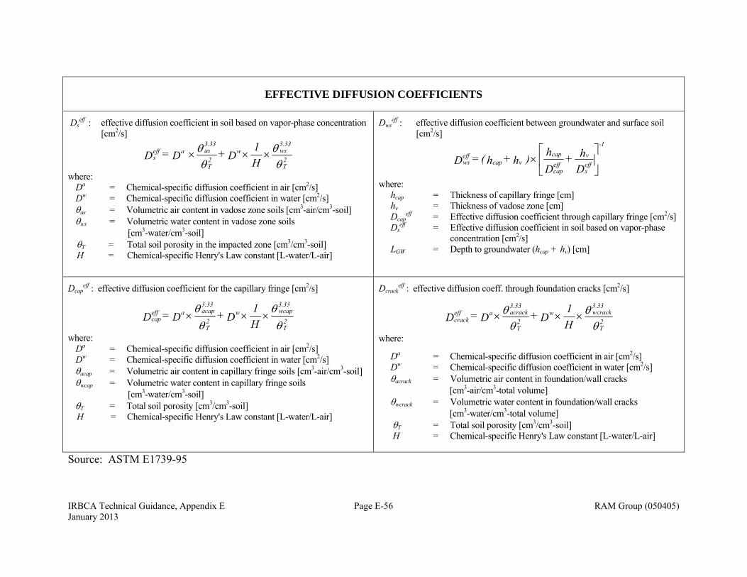
IRBCA Technical Guidance, Appendix E Page E-56 RAM Group (050405) January 2013
EFFECTIVE DIFFUSION COEFFICIENTS
Dseff : effective diffusion coefficient in soil based on vapor-phase concentration
[cm2/s]
2T
3.33wsw
2T
3.33asaeff
s H1 D + D = D
where: Da = Chemical-specific diffusion coefficient in air [cm2/s] Dw = Chemical-specific diffusion coefficient in water [cm2/s] as = Volumetric air content in vadose zone soils [cm3-air/cm3-soil] ws = Volumetric water content in vadose zone soils [cm3-water/cm3-soil] T = Total soil porosity in the impacted zone [cm3/cm3-soil] H = Chemical-specific Henry's Law constant [L-water/L-air]
Dwseff : effective diffusion coefficient between groundwater and surface soil
[cm2/s]
Dh +
Dh ) h + h( = D eff
s
veffcap
cap-1
vcapeffws
where: hcap = Thickness of capillary fringe [cm] hv = Thickness of vadose zone [cm] Dcap
eff = Effective diffusion coefficient through capillary fringe [cm2/s] Ds
eff = Effective diffusion coefficient in soil based on vapor-phase concentration [cm2/s]
LGW = Depth to groundwater (hcap + hv) [cm]
Dcapeff : effective diffusion coefficient for the capillary fringe [cm2/s]
2T
3.33wcapw
2T
3.33acapaeff
cap H1 D + D = D
where: Da = Chemical-specific diffusion coefficient in air [cm2/s] Dw = Chemical-specific diffusion coefficient in water [cm2/s] acap = Volumetric air content in capillary fringe soils [cm3-air/cm3-soil] wcap = Volumetric water content in capillary fringe soils [cm3-water/cm3-soil] T = Total soil porosity [cm3/cm3-soil] H = Chemical-specific Henry's Law constant [L-water/L-air]
Dcrackeff : effective diffusion coeff. through foundation cracks [cm2/s]
2T
3.33wcrackw
2T
3.33acrackaeff
crack H1 D + D = D
where:
Da = Chemical-specific diffusion coefficient in air [cm2/s] Dw = Chemical-specific diffusion coefficient in water [cm2/s] acrack = Volumetric air content in foundation/wall cracks [cm3-air/cm3-total volume] wcrack = Volumetric water content in foundation/wall cracks [cm3-water/cm3-total volume] T = Total soil porosity [cm3/cm3-soil] H = Chemical-specific Henry's Law constant [L-water/L-air]
Source: ASTM E1739-95
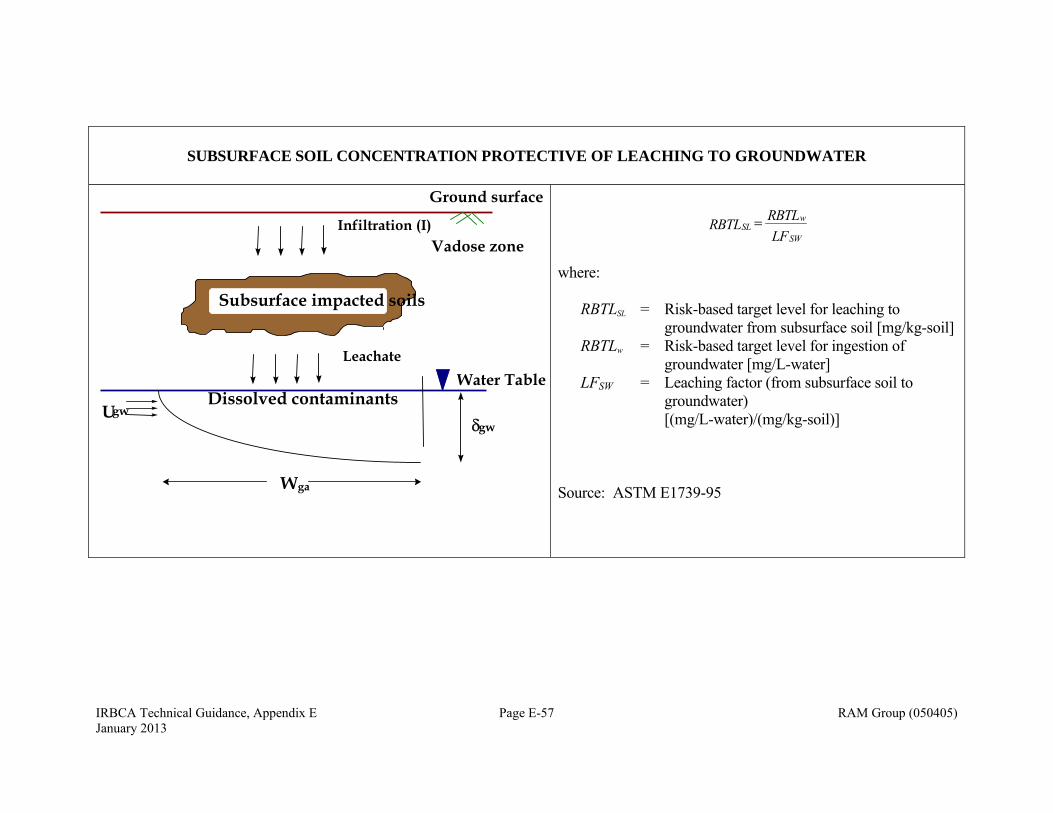
IRBCA Technical Guidance, Appendix E Page E-57 RAM Group (050405) January 2013
SUBSURFACE SOIL CONCENTRATION PROTECTIVE OF LEACHING TO GROUNDWATER
SLw
SWRBTL RBTL
LF
where: RBTLSL = Risk-based target level for leaching to
groundwater from subsurface soil [mg/kg-soil] RBTLw = Risk-based target level for ingestion of
groundwater [mg/L-water] LFSW = Leaching factor (from subsurface soil to
groundwater) [(mg/L-water)/(mg/kg-soil)] Source: ASTM E1739-95
Ground surface
Vadose zone
Water TableLeachate
Wga
Subsurface impacted soils
Infiltration (I)
gwUgw
Dissolved contaminants
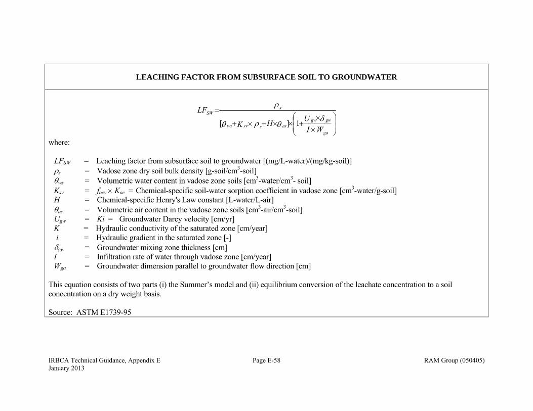
IRBCA Technical Guidance, Appendix E Page E-58 RAM Group (050405) January 2013
LEACHING FACTOR FROM SUBSURFACE SOIL TO GROUNDWATER
ga
gwgwasssvws
sSW
WIUHK
LF
1][
where: LFSW = Leaching factor from subsurface soil to groundwater [(mg/L-water)/(mg/kg-soil)] s = Vadose zone dry soil bulk density [g-soil/cm3-soil] ws = Volumetric water content in vadose zone soils [cm3-water/cm3- soil] Ksv = focv Koc = Chemical-specific soil-water sorption coefficient in vadose zone [cm3-water/g-soil] H = Chemical-specific Henry's Law constant [L-water/L-air] as = Volumetric air content in the vadose zone soils [cm3-air/cm3-soil] Ugw = Ki = Groundwater Darcy velocity [cm/yr] K = Hydraulic conductivity of the saturated zone [cm/year] i = Hydraulic gradient in the saturated zone [-] gw = Groundwater mixing zone thickness [cm] I = Infiltration rate of water through vadose zone [cm/year] Wga = Groundwater dimension parallel to groundwater flow direction [cm] This equation consists of two parts (i) the Summer’s model and (ii) equilibrium conversion of the leachate concentration to a soil concentration on a dry weight basis. Source: ASTM E1739-95
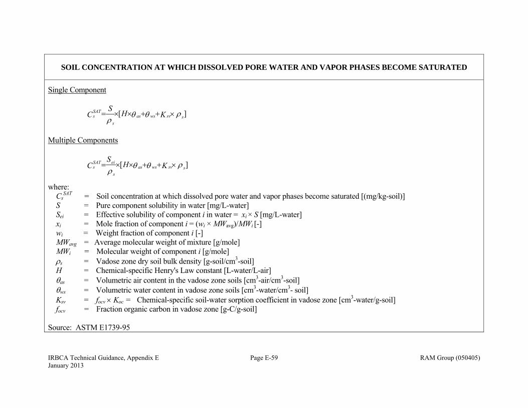
IRBCA Technical Guidance, Appendix E Page E-59 RAM Group (050405) January 2013
SOIL CONCENTRATION AT WHICH DISSOLVED PORE WATER AND VAPOR PHASES BECOME SATURATED
Single Component
][
ssvwsass
SATs KHS
C
Multiple Components
][
ssvwsass
eiSATs KH
SC
where: Cs
SAT = Soil concentration at which dissolved pore water and vapor phases become saturated [(mg/kg-soil)] S = Pure component solubility in water [mg/L-water] Sei = Effective solubility of component i in water = xi × S [mg/L-water] xi = Mole fraction of component i = (wi × MWavg)/MWi [-] wi = Weight fraction of component i [-] MWavg = Average molecular weight of mixture [g/mole] MWi = Molecular weight of component i [g/mole] s = Vadose zone dry soil bulk density [g-soil/cm3-soil] H = Chemical-specific Henry's Law constant [L-water/L-air] as = Volumetric air content in the vadose zone soils [cm3-air/cm3-soil] ws = Volumetric water content in vadose zone soils [cm3-water/cm3- soil] Ksv = focv Koc = Chemical-specific soil-water sorption coefficient in vadose zone [cm3-water/g-soil] focv = Fraction organic carbon in vadose zone [g-C/g-soil]
Source: ASTM E1739-95
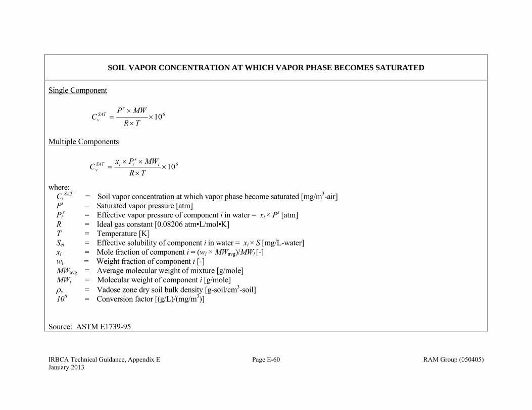
IRBCA Technical Guidance, Appendix E Page E-60 RAM Group (050405) January 2013
SOIL VAPOR CONCENTRATION AT WHICH VAPOR PHASE BECOMES SATURATED
Single Component
610
TRMWP
Cs
SATv
Multiple Components
610
TRMWPx
C is
iiSATv
where: Cv
SAT = Soil vapor concentration at which vapor phase become saturated [mg/m3-air] Ps = Saturated vapor pressure [atm] Pi
s = Effective vapor pressure of component i in water = xi × Ps [atm] R = Ideal gas constant [0.08206 atm•L/mol•K] T = Temperature [K] Sei = Effective solubility of component i in water = xi × S [mg/L-water] xi = Mole fraction of component i = (wi × MWavg)/MWi [-] wi = Weight fraction of component i [-] MWavg = Average molecular weight of mixture [g/mole] MWi = Molecular weight of component i [g/mole] s = Vadose zone dry soil bulk density [g-soil/cm3-soil] 106 = Conversion factor [(g/L)/(mg/m3)]
Source: ASTM E1739-95

IRBCA Technical Guidance, Appendix E Page E-61 RAM Group (050405) January 2013
DOMENICO MODEL: DILUTION ATTENUATION FACTOR (DAF) IN THE SATURATED ZONE
Domenico model for multi-dimensional transport with decay and continuous source:
x 2 Z-z erf -
x 2 Z+z erf
x 2Y/2 -y erf -
x 2Y/2 +y erf
tv
vvtx
erfcv
xexpC
tzyxC
zzyy
o
2
4
+ 1
4
+ 1 - 1 2
)8/1( = ),,,(
x
x
x
x
where:
C = Dissolved-phase concentration [mg/L] Co = Dissolved-phase concentration at the source (at x=y=z=0) [mg/L] v = Retarded seepage velocity [m/sec] = Overall first order bio-decay rate [1/day] x = Longitudinal dispersivity [m] y = Lateral dispersivity [m] z = Vertical dispersivity [m] x, y, z = Spatial coordinates [m] t = Time [day] x = Distance along the centerline measured from the downgradient
edge of the groundwater source [m] Y = GW source dimension perpendicular to GW flow direction [m] Z = GW source (mixing zone) thickness [m] DA Fsat = Co/C(x)
At the centerline, for steady-state (after a long time) the concentration can be obtained by setting y = 0, z = 0, and x << v t as:
x Z erf
x Y erf
vxexp
CxC
zy
o
24
4
+ 1 - 1 2
= )( x
x
At the centerline, for steady-state the concentration without decay can be obtained by setting y = 0, z = 0, x << vt, and = 0 as:
x Z erf
x Y erf
CxC
zyo 24 =
)(
Note: Compare to ASTM E1739-95, p. 31, where Y = Sw Z = Sd, v = u, and Co = Csource Source: Domenico, P.A. and F.W. Schwartz, 1990, Physical and Chemical Hydrogeology. John Wiley and Sons, NY, 824 p. (Eqn. 17.21)
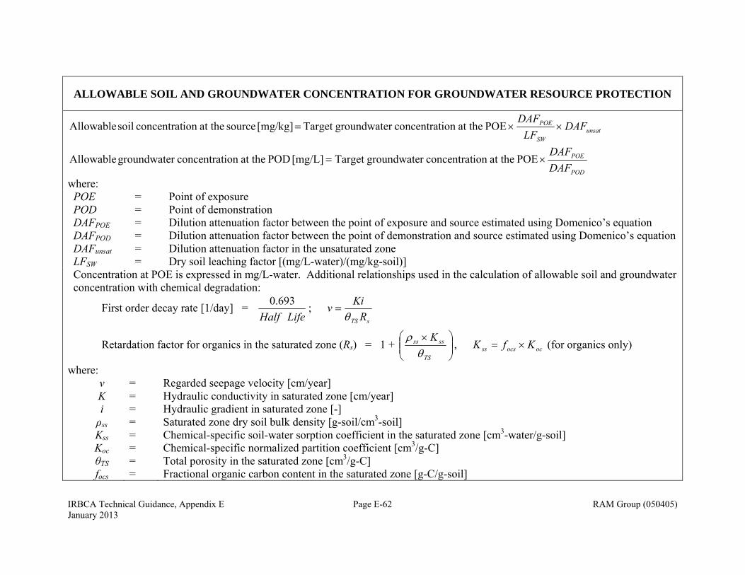
IRBCA Technical Guidance, Appendix E Page E-62 RAM Group (050405) January 2013
ALLOWABLE SOIL AND GROUNDWATER CONCENTRATION FOR GROUNDWATER RESOURCE PROTECTION
unsatSW
POE DAFLF
DAF POE at theion concentratr groundwateTarget [mg/kg] source at theion concentrat soil Allowable
POD
POE
DAFDAF
POE at theion concentratr groundwateTarget [mg/L] POD at theion concentratr groundwate Allowable
where: POE POD DAFPOE DAFPOD DAFunsat LFSW
= = = = = =
Point of exposure Point of demonstration Dilution attenuation factor between the point of exposure and source estimated using Domenico’s equation Dilution attenuation factor between the point of demonstration and source estimated using Domenico’s equation Dilution attenuation factor in the unsaturated zone Dry soil leaching factor [(mg/L-water)/(mg/kg-soil)]
Concentration at POE is expressed in mg/L-water. Additional relationships used in the calculation of allowable soil and groundwater concentration with chemical degradation:
First order decay rate [1/day] = LifeHalf
693.0;
sTS RKiv
Retardation factor for organics in the saturated zone (Rs) = 1 +
TS
ssss K
, ococsss KfK (for organics only)
where: v K i ρss Kss Koc θTS focs
= = = = = = = =
Regarded seepage velocity [cm/year] Hydraulic conductivity in saturated zone [cm/year] Hydraulic gradient in saturated zone [-] Saturated zone dry soil bulk density [g-soil/cm3-soil] Chemical-specific soil-water sorption coefficient in the saturated zone [cm3-water/g-soil] Chemical-specific normalized partition coefficient [cm3/g-C] Total porosity in the saturated zone [cm3/g-C] Fractional organic carbon content in the saturated zone [g-C/g-soil]
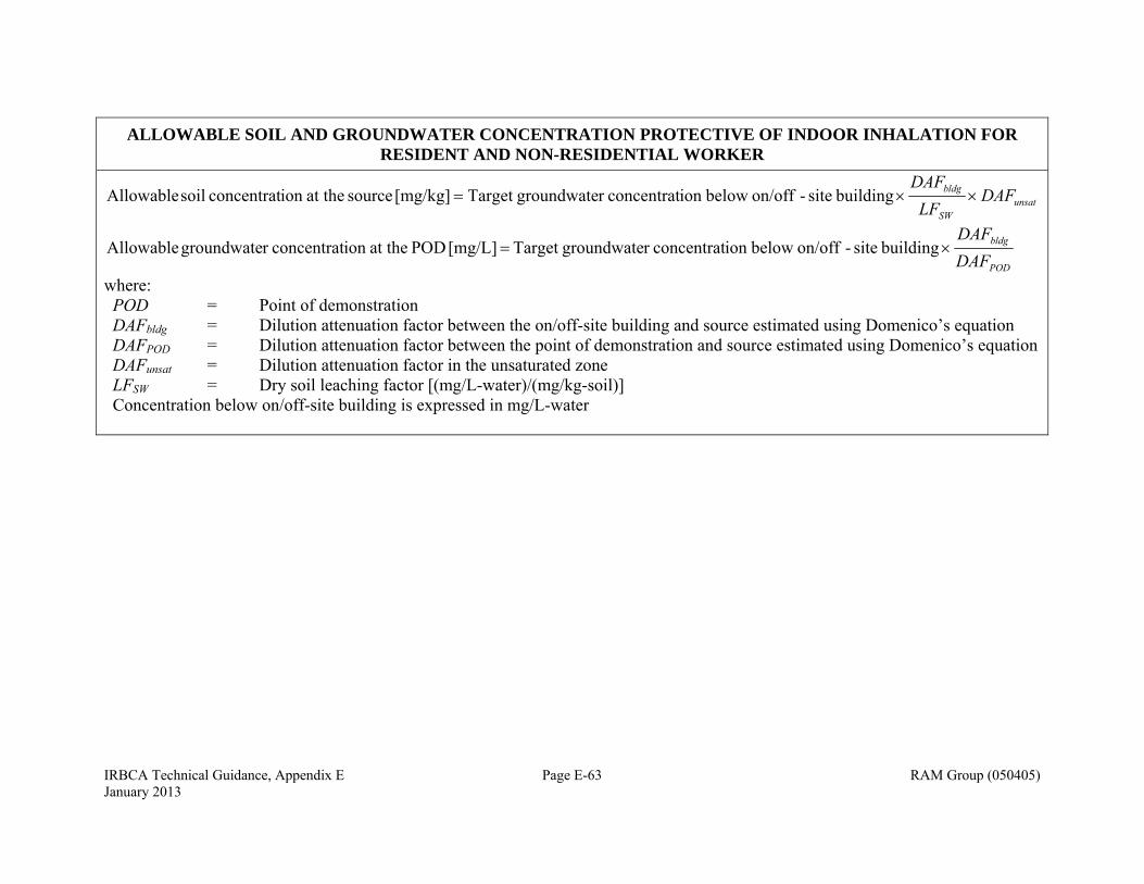
IRBCA Technical Guidance, Appendix E Page E-63 RAM Group (050405) January 2013
ALLOWABLE SOIL AND GROUNDWATER CONCENTRATION PROTECTIVE OF INDOOR INHALATION FOR RESIDENT AND NON-RESIDENTIAL WORKER
unsatSW
bldg DAFLF
DAF building site-on/off belowion concentratr groundwateTarget [mg/kg] source at theion concentrat soil Allowable
POD
bldg
DAFDAF
building site-on/off belowion concentratr groundwateTarget [mg/L] POD at theion concentratr groundwate Allowable
where: POD DAFbldg DAFPOD DAFunsat LFSW
= = = = =
Point of demonstration Dilution attenuation factor between the on/off-site building and source estimated using Domenico’s equation Dilution attenuation factor between the point of demonstration and source estimated using Domenico’s equation Dilution attenuation factor in the unsaturated zone Dry soil leaching factor [(mg/L-water)/(mg/kg-soil)]
Concentration below on/off-site building is expressed in mg/L-water
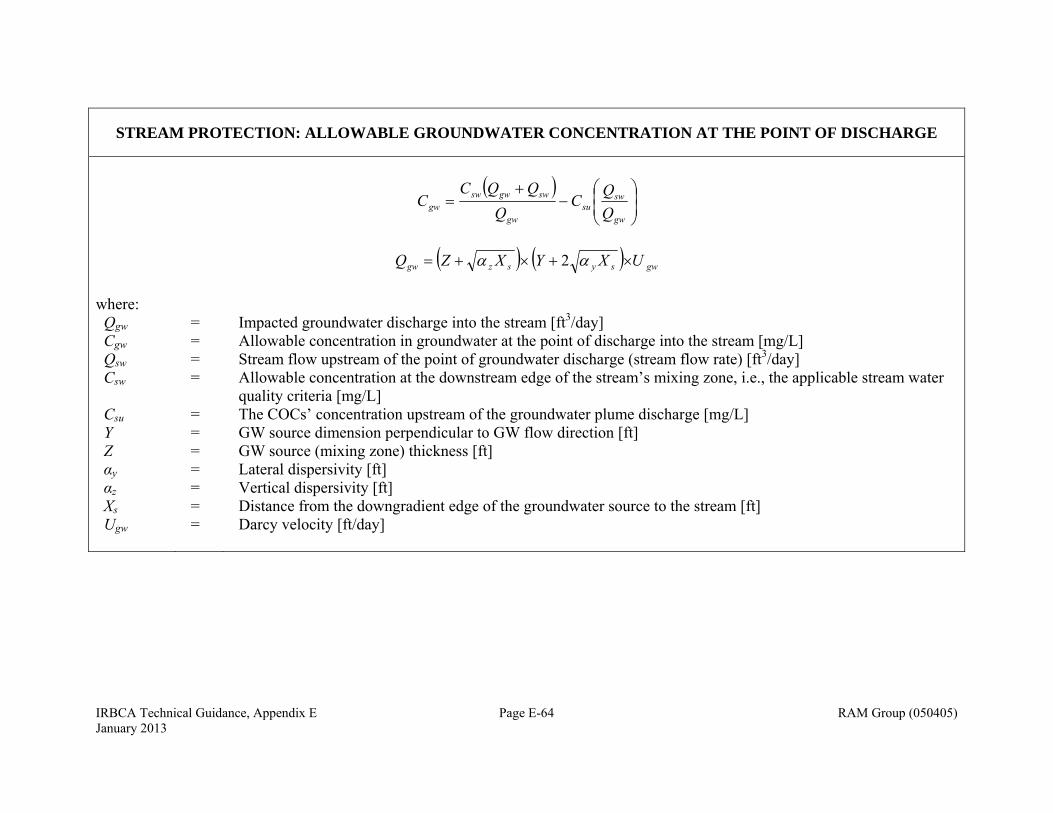
IRBCA Technical Guidance, Appendix E Page E-64 RAM Group (050405) January 2013
STREAM PROTECTION: ALLOWABLE GROUNDWATER CONCENTRATION AT THE POINT OF DISCHARGE
gw
swsu
gw
swgwswgw Q
QC
QQQC
C
gwsyszgw UXYXZQ 2
where: Qgw Cgw Qsw Csw Csu Y Z αy αz Xs Ugw
= = = = = = = = = = =
Impacted groundwater discharge into the stream [ft3/day] Allowable concentration in groundwater at the point of discharge into the stream [mg/L] Stream flow upstream of the point of groundwater discharge (stream flow rate) [ft3/day] Allowable concentration at the downstream edge of the stream’s mixing zone, i.e., the applicable stream water quality criteria [mg/L] The COCs’ concentration upstream of the groundwater plume discharge [mg/L] GW source dimension perpendicular to GW flow direction [ft] GW source (mixing zone) thickness [ft] Lateral dispersivity [ft] Vertical dispersivity [ft] Distance from the downgradient edge of the groundwater source to the stream [ft] Darcy velocity [ft/day]
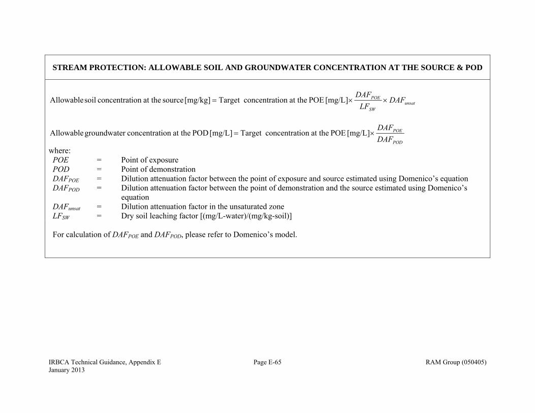
IRBCA Technical Guidance, Appendix E Page E-65 RAM Group (050405) January 2013
STREAM PROTECTION: ALLOWABLE SOIL AND GROUNDWATER CONCENTRATION AT THE SOURCE & POD
unsatSW
POE DAFLF
DAF [mg/L] POE at theion concentratTarget [mg/kg] source at theion concentrat soil Allowable
POD
POE
DAFDAF
[mg/L] POE at theion concentratTarget [mg/L] POD at theion concentratr groundwate Allowable
where: POE POD DAFPOE DAFPOD DAFunsat LFSW
= = = = = =
Point of exposure Point of demonstration Dilution attenuation factor between the point of exposure and source estimated using Domenico’s equation Dilution attenuation factor between the point of demonstration and the source estimated using Domenico’s equation Dilution attenuation factor in the unsaturated zone Dry soil leaching factor [(mg/L-water)/(mg/kg-soil)]
For calculation of DAFPOE and DAFPOD, please refer to Domenico’s model.

IRBCA Technical Guidance, Appendix F RAM Group (050405) November 2013
APPENDIX F DEFINITIONS
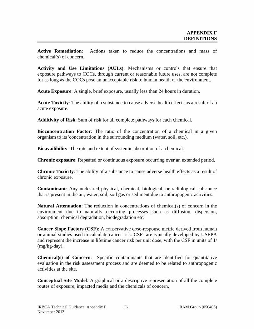
IRBCA Technical Guidance, Appendix F RAM Group (050405) November 2013
F-1
APPENDIX F DEFINITIONS
Active Remediation: Actions taken to reduce the concentrations and mass of chemical(s) of concern. Activity and Use Limitations (AULs): Mechanisms or controls that ensure that exposure pathways to COCs, through current or reasonable future uses, are not complete for as long as the COCs pose an unacceptable risk to human health or the environment. Acute Exposure: A single, brief exposure, usually less than 24 hours in duration. Acute Toxicity: The ability of a substance to cause adverse health effects as a result of an acute exposure. Additivity of Risk: Sum of risk for all complete pathways for each chemical. Bioconcentration Factor: The ratio of the concentration of a chemical in a given organism to its 'concentration in the surrounding medium (water, soil, etc.). Bioavailibility: The rate and extent of systemic absorption of a chemical. Chronic exposure: Repeated or continuous exposure occurring over an extended period. Chronic Toxicity: The ability of a substance to cause adverse health effects as a result of chronic exposure. Contaminant: Any undesired physical, chemical, biological, or radiological substance that is present in the air, water, soil, soil gas or sediment due to anthropogenic activities. Natural Attenuation: The reduction in concentrations of chemical(s) of concern in the environment due to naturally occurring processes such as diffusion, dispersion, absorption, chemical degradation, biodegradation etc. Cancer Slope Factors (CSF): A conservative dose-response metric derived from human or animal studies used to calculate cancer risk. CSFs are typically developed by USEPA and represent the increase in lifetime cancer risk per unit dose, with the CSF in units of 1/ (mg/kg-day). Chemical(s) of Concern: Specific contaminants that are identified for quantitative evaluation in the risk assessment process and are deemed to be related to anthropogenic activities at the site. Conceptual Site Model: A graphical or a descriptive representation of all the complete routes of exposure, impacted media and the chemicals of concern.
IRBCA Technical Guidance, Appendix F RAM Group (050405) November 2013
F-2
Corrective Action: The sequence of actions that include site assessment, interim remedial action, remedial action, operation and maintenance of equipment, monitoring of progress, and termination of the remedial action. 7Q10: The average minimum flow of a stream during seven consecutive days that has a probable recurrence interval of once- in-ten years. Cumulative site-wide risk: Sum of risk for all chemicals and all complete routes of exposure. Csat: Soil saturation limit. The concentration in soil at which the absorptive limits of the soil particles, the solubility limits of the soil pore water, and saturation of soil pore air have been reached. Dermal Absorption: The process by which a chemical penetrates the skin and enters the body. Dermal Exposure: Contact between a chemical and the skin. Dermal Toxicity: Adverse effects of a toxicant on the skin. Detection Limit: The lowest concentration of a chemical that can be distinguished from zero or background for a specific analytical method. Dilution Attenuation Factor (DAF): Represents the reduction in the concentration due to the influence of natural attenuation processes as a chemical migrates through the media. The numerical factor by which a contaminant concentration is diminished as the contaminant moves through soil and groundwater from its source to the point of contact. Attenuating effects include adsorption of the contaminant onto soil and aquifer media, chemical transformation, biological degradation, and dilution from mixing of the leachate with ambient groundwater, etc. Direct Exposure Pathway: An exposure pathway where the point of exposure is at the source, without a release to any other medium. Ecological Assessment: A qualitative appraisal of the actual or potential effects of chemical(s) of concern on the ecological receptors: plants and animals and their habitats. Ecological receptor: A living organism e.g. fauna and flora other than a human being and domestic species. Engineering Controls: Modifications to a site or facility (for example, slurry walls, capping, and point of use water treatment) to reduce or eliminate the potential for exposure to a chemical(s) of concern. Exposure: Contact of an organism with chemical(s) of concern at the exchange boundaries (for example, skin, lungs, and liver) and available for absorption.
IRBCA Technical Guidance, Appendix F RAM Group (050405) November 2013
F-3
Exposure Assessment: The determination or estimation (qualitative or quantitative) of the magnitude, frequency, duration, and route of exposure. Exposure Domain: Contaminated area that can result in exposure to a particular receptor by a specified route of exposure. Exposure Pathway: Physical migration of contaminants from sources to the receptor. An exposure pathway describes a unique mechanism by which an individual or population (human and ecological receptor or ecological habitat) is exposed to a chemical(s) of concern and its byproducts originating from a site. Each exposure pathway includes a source or release from a source, a point of exposure, an exposure route and a receptor. If the exposure point is distant from the source, a transport/exposure medium (for example, air) or media also is included. Exposure Route: The manner in which a chemical(s) of concern comes in contact with an organism (for example, ingestion, inhalation, and dermal contact). Exposure Unit: A site may be divided into multiple exposure units each homogenous in terms of the exposure and risk characteristics. For example a large operating commercial site may be divided into two exposure units. An exposure unit that includes the parking lot only and an exposure unit that includes the building only. For residential land use involving single-family dwellings, the exposure unit is typically the residential lot. If land is not currently used for residential purposes, but could be developed as such in the future, assessment of the site must consider potential residential exposure units. IRBCA considers the default residential lot to be 0.25 dunam. Facility: The property containing the source of the chemical(s) of concern where a release has occurred. Habitat: A place where an ecological receptor such as an animal or plant normally lives, reproduces, and hibernates. Hazard Index: The sum of two or more hazard quotients (HQ) for multiple chemical(s) of concern or multiple exposure pathways, or both and can be used to predict the non-cancer risk of simultaneous exposure of a receptor to several chemicals. Hazard Quotients: The ratio of the dose to the reference dose for that chemical. Hydraulic Conductivity: The volume of water at the existing kinematic viscosity that will move in unit time under a unit hydraulic gradient through a unit area measured at right angles to the direction of flow. Hyporheic Zone: Region beneath and adjacent to streams and rivers where surface and groundwater mix.
IRBCA Technical Guidance, Appendix F RAM Group (050405) November 2013
F-4
Incremental Carcinogenic Risk Levels: The potential for incremental carcinogenic human health effects due to exposure to the chemical(s) of concern. Indirect Exposure Pathways: An exposure pathway where there exists at least one media (soil, groundwater, air) between the source and the point(s) of exposure. To quantify dose and risk evaluation for such a pathway requires the application of a model. Institutional Controls: The restriction on use or access (for example, fences, deed restrictions, restrictive zoning) to a site or facility to eliminate or minimize potential exposure to a chemical(s) of concern. Interim Remedial Action: The course of action to mitigate fire and safety hazards and to prevent further migration of hydrocarbons in their vapor, dissolved, or liquid phase. Integrated Exposure Uptake Biokinetic Model- IEUBK: A model developed by the USEPA to predict blood lead concentrations in children resulting from exposure to lead in soil and other sources. Integrated Risk Information System (IRIS): A USEPA electronic database containing toxicity values (e.g., reference doses and slope factors) and other details for each chemical. Karst: A distinctive set of geomorphic landforms resulting from the development of extensive subsurface solution channels and caves in carbonate rocks (Boulding, 1995). Kd: Soil-water organic partition coefficient for organics. LC50: Median Lethal Concentration. The concentration of a toxicant that is lethal to 50 percent of the test organisms within a designated period of time. LD50: Median Lethal Dose. The dose of a toxicant that is lethal to 50 percent of the test organisms within a designated period of time. Lowest Observable Adverse Effect Level (LOAEL): The lowest dose of a chemical observed to cause an adverse effect. Long-Term Stewardship: An appropriate system of controls, institutions and information necessary to fully protect human health and the environment into perpetuity with demonstrated ability and feasible registration, long-term control by the authorities, including municipal authorities and their enforcement. Maximum Contaminant Level (MCL): A standard for drinking water established by USEPA under the Safe Drinking Water Act, which is the maximum permissible level of chemical(s) of concern in water that is delivered to any user of a public water supply. In Israel these levels are called: IWDS- Israeli Water Drinking Standard.
IRBCA Technical Guidance, Appendix F RAM Group (050405) November 2013
F-5
Mixing Zone: An area of dilution of effluent in the receiving water beyond which chronic toxicity criteria must be met. Natural Biodegradation: The reduction in concentration of chemical(s) of concern through naturally occurring microbial activity. No Observable Adverse Effect Level (NOAEL): The highest dose of a chemical that does not produce an observable adverse health effect. Off-site: Areas beyond the site that can potentially become contaminated. Point of Demonstration: A point located between the source and the point of exposure where measurements are made to predict the concentrations at the POE. Point of Exposure: The point where exposure occurs i.e., the location where chemicals enter the human body or the body of the ecological receptor or its habitat. Practical Quantitation Limit: Lowest concentration that can be reliably quantified within specified limits of precision and accuracy during routine laboratory operating conditions. Preliminary Remediation Goals (PRGs): risk-based concentrations developed by USEPA R IX. These were replaced by Regions 3/6/9 Regional Screening Levels (RSLs). Qualitative Risk Analysis: A nonnumeric evaluation of a site to determine potential exposure pathways and receptors based on known or readily available information. Reasonable Maximum Exposure (RME): The highest exposure that is reasonably expected to occur at a site. RMEs are estimated for individual pathways or a combination of exposure pathways. Reasonable Potential Exposure Scenario: A situation with a credible chance of occurrence where a receptor may become directly or indirectly exposed to the chemical(s) of concern without considering extreme or essentially impossible circumstances. Reasonably Anticipated Future Use: Future use of a site or facility that can be predicted with a high degree of certainty given current use, local government planning, and zoning. Receptor: Human, structures, utilities, surface waters, seawater, sediments and ecological risk receptors (flora and fauna and their habitats) which may be adversely affected by a release and potentially be subject to damage by exposure to COCs and/or their by products via ingestion, inhalation, or absorption or dermal contact. This definition also specifically includes water-supply wells because it must be assumed that humans will be ingesting the water from these wells.
IRBCA Technical Guidance, Appendix F RAM Group (050405) November 2013
F-6
Reference Concentration (RfC): An estimate of the concentration of a toxicant that is likely to be without appreciable risk of adverse effects during a lifetime of continuous exposure. Reference Dose (RfD): A preferred toxicity value for evaluating potential non-carcinogenic effects in humans resulting from exposure to a chemical(s) of concern. If the threshold for the most sensitive health effect can be identified - the effect that occurs at the lowest dose - limiting exposure to produce doses below that threshold should protect against all of the effects of the chemical. This concept is the basis for the USEPA reference dose (RfD). Remediation/Remedial Action: Activities conducted to protect human health, safety, and the environment. These activities include evaluating risk, site cleanup, making no-further-action determinations, monitoring controls, engineering controls, and designing and operating cleanup equipment. Remediating Party: All entities and their designees, collectively and generically, such as responsible parties, development interests, landowners and others directly involved in the remediation of a particular contaminated site Representative Concentration: The concentration that represents the effective concentration to which a receptor is exposed by a specified pathway. Risk Assessment: An analysis of the potential for adverse health effects caused by chemical(s) of concern at a site to determine the need for remedial action or the need to develop target levels to design remedial action. Risk Reduction: The lowering or elimination of the level of risk posed to human health or the environment through interim remedial action, remedial action, or institutional or engineering controls. Risk-Based Screening Level/Screening Levels (RBSLs): Risk-based site-specific corrective action target levels for chemical(s) of concern developed under the Tier 1 evaluation. Route of Exposure: The manner or mechanism by which a COC affects a receptor, for example, ingestion or inhalation Sensitivity Analysis: Evaluation of the calculated risk or target levels for different alternatives of possible input parameters. Site: The area(s) defined by the extent of migration of the chemical(s) of concern - areal extent of contamination. Site Assessment: An evaluation of subsurface geology, hydrology, and surface characteristics to determine if a release has occurred, the levels of the chemical(s) of
IRBCA Technical Guidance, Appendix F RAM Group (050405) November 2013
F-7
concern, and the extent of the migration of the chemical(s) of concern. The site assessment collects data on groundwater quality and potential receptors and generates information to support remedial action decisions. Site Classification: A qualitative evaluation of a site based on known or readily available information to identify the need for interim remedial actions and further information gathering. Site classification is intended to specifically prioritize sites. Site Specific Target Levels (SSTLs): Risk-based remedial action target levels for chemical(s) of concern developed for a particular site under the Tier 2 and Tier 3 evaluations. Site-Specific: Activities, information, and data unique to a particular site. Sources: Points of entry of contaminants into possible exposure pathways. In the case of hydrocarbons and chlorinated organic compounds releases, the non-aqueous phase liquid (NAPL) which can either dissolve into the aqueous phase or volatilize into the gaseous phase constitutes a source. Primary sources include underground tanks and associated piping, lagoons, landfills etc. For risk assessment purposes, as an example, the dissolved plume in groundwater may be the source for the inhalation exposure pathway. Source Area(s): Either the location of liquid hydrocarbons or the location of highest soil and groundwater concentrations of the chemical(s) of concern. Surficial Soil: The upper layer of the soil, between ground level and a predetermined depth (see text). Subsurface Soil: The soil layer between the bottom of the surficial soil layer and the water table. Target Levels: Numeric values or other performance criteria that are protective of human health, safety, and the environment. Tier 1 Risk Assessment: A risk-based analysis to develop non-site-specific values for direct and indirect exposure pathways utilizing conservative exposure factors and fate and transport for potential pathways and various property use categories (for example, residential, commercial, and industrial uses). Values established under Tier 1 will apply to all sites that fall into a particular category. Tier 2 Risk Assessment: A risk-based analysis applying the direct exposure values established under a Tier 1 risk assessment at the point(s) of exposure developed for a specific site and development of values for potential indirect exposure pathways at the point(s) of exposure based on site-specific conditions. Tier 3 Risk Assessment: A risk-based analysis to develop values for potential direct and indirect exposure pathways at the point(s) of exposure based on site-specific conditions.

IRBCA Technical Guidance, Appendix F RAM Group (050405) November 2013
F-8
95% UCL: Upper confidence limit of the average. Several methods are available for calculating a 95% UCL on the mean for a set of data. However, the performance of these methods varies dramatically and is dependent on the nature of the data set (e.g., number of values, their distribution and variability, the extent of censoring). For calculating 95% UCL values, IRBCA recommends using the FLUCL tool. This program calculates a 95% UCL using the optimal method, given the characteristics of the data. FLUCL is particularly useful for data sets that include censored values (i.e., with "non-detects"). IRBCA also considers the most recent version of USEPA's ProUCL, to be acceptable. Other computational tools for calculating 95% UCL can be used, if approved by the authorities. In cases where the 95% UCL exceeds the highest concentration, the latter is used as the representative concentration. User: An individual or group involved in the RBCA process including owners, operators, regulators, underground storage tank (UST) fund managers, attorneys, consultants, legislators, and so forth. Very Strict Levels (VSLs): The MoEP default cleanup levels that allow unrestricted land use. They are determined according to land use. Volatilization Factor: A measure of the process of transfer of a chemical from the aqueous or liquid phase to the gas phase under specific environmental conditions and exposure durations.