Embed Size (px)
Citation preview
© ISO 2008 – All rights reserved
Document type: International Standard Document subtype: Document stage: (20) Preparatory Document language: E H:\Sicks\I S O\TG2 FACS - 5th wheels\N 20 Draft FACS-5th wheels 10 July08.doc STD Version 2.2
ISO/TC22/SC15 N Date: 2008-10-15
ISO/WD 13044-2
ISO/TC 22/SC 15/WG 4
Secretariat: UNI
Road vehicles — Fully automatic coupling systems 24V (FACS) for heavy commercial vehicle combinations — Part 2: 50 mm fifth wheel couplings - electrical and pneumatic interface
Véhicules routiers — Dispositifs d'attelages entièrement automatiques 24V (FACS) pour ensembles routiers lourds — Partie 2: 50 mm sellette d'attelage pour pivot - interface électrique at pneumatique
Warning
This document is not an ISO International Standard. It is distributed for review and comment. It is subject to change without notice and may not be referred to as an International Standard.
Recipients of this draft are invited to submit, with their comments, notification of any relevant patent rights of which they are aware and to provide supporting documentation.
ISO/TC22/SC15/WG4/TG2 N 20
ISO/WD 13044-2
ii © ISO 2008 – All rights reserved
Copyright notice
This ISO document is a working draft or committee draft and is copyright-protected by ISO. While the reproduction of working drafts or committee drafts in any form for use by participants in the ISO standards development process is permitted without prior permission from ISO, neither this document nor any extract from it may be reproduced, stored or transmitted in any form for any other purpose without prior written permission from ISO.
Requests for permission to reproduce this document for the purpose of selling it should be addressed as shown below or to ISO's member body in the country of the requester:
[Indicate the full address, telephone number, fax number, telex number, and electronic mail address, as appropriate, of the Copyright Manager of the ISO member body responsible for the secretariat of the TC or SC within the framework of which the working document has been prepared.]
Reproduction for sales purposes may be subject to royalty payments or a licensing agreement.
Violators may be prosecuted.
ISO/WD 13044-2
© ISO 2008 – All rights reserved iii
Contents Page
Foreword ............................................................................................................................................................ iv Introduction.........................................................................................................................................................v 1 Scope......................................................................................................................................................1 2 Normative references............................................................................................................................1 3 Terms and definitions ...........................................................................................................................2 4 Requirements.........................................................................................................................................2 4.1 Tractor and semi-trailer ........................................................................................................................2 4.2 Mechanical interface .............................................................................................................................2 4.3 EPI module .............................................................................................................................................3 4.4 Mating of the two EPI parts ..................................................................................................................3 4.5 Guiding and alignment..........................................................................................................................3 4.5.1 Manoeuvrability of truck-sided EPI module........................................................................................3 4.5.2 Manoeuvrability of trailer-sided EPI module ......................................................................................4 4.6 Encapsulation and protection..............................................................................................................5 4.7 Future developments ............................................................................................................................5 4.8 Landing legs ..........................................................................................................................................5 5 Tests and specific requirements .........................................................................................................6 5.1 General ...................................................................................................................................................6 5.2 Connection and disconnection............................................................................................................6 5.3 Endurance ..............................................................................................................................................6 6 Supplementary transitional features ...................................................................................................6 6.1 General ...................................................................................................................................................6 6.2 Tractor vehicles .....................................................................................................................................7 6.3 Semi-trailers...........................................................................................................................................7 Annex A (normative) EPI module - dimensional characteristics.................................................................8 Annex B (normative) EPI module - contact allocation ..................................................................................17
ISO/WD 13044-2
iv © ISO 2008 – All rights reserved
Foreword
ISO (the International Organization for Standardization) is a worldwide federation of national standards bodies (ISO member bodies). The work of preparing International Standards is normally carried out through ISO technical committees. Each member body interested in a subject for which a technical committee has been established has the right to be represented on that committee. International organizations, governmental and non-governmental, in liaison with ISO, also take part in the work. ISO collaborates closely with the International Electrotechnical Commission (IEC) on all matters of electrotechnical standardization.
International Standards are drafted in accordance with the rules given in the ISO/IEC Directives, Part 2.
The main task of technical committees is to prepare International Standards. Draft International Standards adopted by the technical committees are circulated to the member bodies for voting. Publication as an International Standard requires approval by at least 75 % of the member bodies casting a vote.
Attention is drawn to the possibility that some of the elements of this document may be the subject of patent rights. ISO shall not be held responsible for identifying any or all such patent rights.
ISO 13044-2 was prepared by Technical Committee ISO/TC 22, Road vehicles, Subcommittee SC 15, Interchangeability of components.
ISO 13044 consists of the following parts, under the general title Road vehicles — Fully automatic coupling systems 24V (FACS) for heavy commercial vehicle combinations:
⎯ Part 1: General requirements and definitions
⎯ Part 2: 50 mm fifth wheel couplings - electrical and pneumatic interface
ISO/WD 13044-2
© ISO 2008 – All rights reserved v
Introduction
This International Standard specifies an automated fifth wheel coupling system with integrated electrical and pneumatic connections for articulated vehicles.
Automated coupling systems facilitate the improvement of safety and comfort of articulated vehicles.
a) Higher safety standards
⎯ reduction of operational accidents,
⎯ less injured drivers because no need for driver to stay in the dangerous zone between truck and trailer while uncoupling,
b) Higher comfort level
⎯ automated coupling systems eliminate necessity to access to low 5th wheels or trailer couplings,
⎯ higher comfort makes "Driver-Job" easier and more safe,
⎯ new components create space for future extensions and potentials,
c) Cost reduction for end user
⎯ less inactive periods for truck and trailer due to less damage and repair,
⎯ less repair and maintenance of cables and pipes.

WORKING DRAFT ISO/WD 13044-2
© ISO 2008 – All rights reserved 1
Road vehicles — Fully automatic coupling systems 24V (FACS) for heavy commercial vehicle combinations — Part 2: 50 mm fifth wheel couplings - electrical and pneumatic interface
1 Scope
This part of ISO 13044 specifies the mechanical, electrical/electronic and pneumatic characteristics of a fully automated fifth wheel coupling system to ensure interchangeability between a tractor vehicle and a coupled semi-trailer(s) with 24 V nominal supply voltage. The two units together constitute an articulated vehicle.
This part of ISO 13044 also supports the smooth introduction of fully automated fifth wheel coupling systems in the market. It specifies features necessary for mixed-mode operation; i.e. the combination of a FACS-equipped tractor vehicle with a conventional semi-trailer, and vice versa, the combination of a conventional tractor vehicle with a FACS-equipped semi-trailer.
This part of ISO 13044 does not provide limitations of maximum gross mass and overall dimensions, which are generally laid down by legislative requirements.
NOTE In order to guarantee best functionality, comfort and safety, the use of FACS is recommended in combination with spring-brake equipped trailers only. FACS does not exonerate the driver from ensuring the trailer is correctly parked before coupling or uncoupling.
2 Normative references
The following referenced documents are indispensable for the application of this document. For dated references, only the edition cited applies. For undated references, the latest edition of the referenced document (including any amendments) applies.
ISO 337, Road vehicles – 50 semi-trailer fifth wheel coupling pin – Basic and mounting interchangeability dimensions
ISO 1726, Road vehicles -- Mechanical coupling between tractors and semi-trailers -- Interchangeability
ISO 1726-2, Road vehicles -- Mechanical couplings between tractors and semi-trailers -- Part 2: Interchange-ability between low-coupling tractors and high-volume semi-trailers
ISO 1728, Road vehicles – Pneumatic braking connections between motor vehicles and towed vehicles -- Interchangeability
ISO 3842, Road vehicles -- Fifth wheels – Interchangeability
ISO 4009, Road vehicles – Towing vehicles – Mounting of electrical and pneumatic connections
ISO 4091, Road vehicles -- Connectors for the electrical connection of towing and towed vehicles -- Definitions, tests and requirements
ISO 4141-1 Road vehicles — Multi-core connecting cables — Part 1: Test methods and requirements for basic performance sheathed cables
ISO/WD 13044-2
2 © ISO 2008 – All rights reserved
ISO 7638-1, Road vehicles -- Connectors for the electrical connection of towing and towed vehicles – Part 1: Connectors for braking systems and running gear of vehicles with 24 V nominal supply voltage
ISO 11992 ((all parts)) Road vehicles — Interchange of digital information on electrical connections between towing and towed vehicles —
ISO 12098, Road vehicles -- Connectors for the electrical connection of towing and towed vehicles -- 15-pole connector for vehicles with 24 V nominal supply voltage
3 Terms and definitions
For the purposes of this part of ISO 9999, the terms and definitions given in Part 1 of this Standard and the following terms and definitions apply.
3.1 fully automated coupling system (FACS) - see Part 1 of this Standard
3.2 electrical/electronic-pneumatic interface module (EPI module) component, combining all electrical/electronic and pneumatic connections in one mating unit, consisting of two complementary parts, the EPI plug module and the EPI socket module
3.2.1 EPI plug module part of the EPI module containing the pin contacts and permanently attached to the kingpin side mounted on the towed vehicle
3.2.2 EPI socket module part of the EPI module containing the socket contacts and permanently attached to the fifth wheel which is mounted to the towing vehicle
4 Requirements
4.1 Tractor and semi-trailer
In order to ensure interchangeability between tractor vehicles and semi-trailers, the requirements of ISO 1726 or ISO 1726-2 shall be met by FACS-equipped vehicles. Particularly the minimum operating dimensions specified in ISO 1726 or ISO 1726-2, such as the articulation angles β1, β2, ω1, ω1 and φ shall not be reduced by the introduction of FACS.
4.2 Mechanical interface
Fifth wheels installed on FACS-equipped tractor vehicles shall comply with the requirements of ISO 3842. Fifth wheel coupling pins (king pins) installed on FACS-equipped semi-trailers shall comply with the requirements of ISO 337. In the event of a failure of the remote control it shall be possible, in an emergency, to open the coupling in at least one other way. If this requires the use of a tool then this shall be included in the vehicle's tool kit. Any manual operation shall not lead to any damages or malfunction of the system components.
ISO/WD 13044-2
© ISO 2008 – All rights reserved 3
4.3 EPI module
4.3.1 EPI plug modules and EPI socket modules in accordance with this Standard shall provide the following electrical connections with 24 V nominal supply voltage:
⎯ 7 poles for the electrical connection of the braking systems and running gear (incl. 2 poles for CAN bus);
⎯ 21 poles for the electrical connection of equipment other than braking systems and running gear, (incl. 2 poles for CAN bus);
⎯ 2 additional poles for future extension.
The dimensional characteristics and location of the EPI module shall be in accordance with the specifications of Annex A. Number, location and functionality shall be in accordance with the specifications of Annex B. Electrical contacts shall only be used as specified.
Caution: Using the electrical contacts for non-specified purposes (including ground) may cause damage to equipment.
4.3.2 EPI plug modules and EPI socket modules in accordance with this Standard shall provide connections for the following two pneumatic braking lines:
⎯ one control line;
⎯ one supply line.
The dimensional characteristics of the pneumatic connections shall be in accordance with the specifications of Annex A.
4.4 Mating of the two EPI parts
Mating of the EPI plug module and the EPI socket module shall be designed to be in driving direction, see Annex A, Figures 1a and 2a. That means that the truck-sided female connectors are ahead of those on the trailer, viewed connected and in direction of motion.
4.5 Guiding and alignment
Guiding and alignment of the EPI module shall be made by a rigid alignment pin in the middle plus two outer pins, which are preferably "floating" designed to provide low forces during EPI mating; see Annex A, Figure A6.
The centre pin shall have the ability to align both EPI parts within a range ± 5 mm in both horizontal and vertical directions. The two outer pins shall ensure the parallel orientation of both EPI parts for connection alignment.
The EPI socket module shall be pre-loaded to avoid any longitudinal movement once the connectors have been engaged. This may be achieved by elastic elements or stored energy. Flexibility shall allow longitudinal movement of max. 30 mm in driving direction. The pre-load force shall be directed to push the connector to the rear, viewed in direction of motion. This means that the connector is pressed forward while coupling, against springs and stored energy.
4.5.1 Manoeuvrability of truck-sided EPI module
The EPI socket module shall have minimum longitudinal manoeuvrability
• in length direction of alignment pin: movable 0-30mm in horizontal direction (positive direction to the rear), pre-loaded with forces min. 200 N, achieved by elastic elements or stored energy. In nominal coupled FACS-position the connector is moved 15mm.
ISO/WD 13044-2
4 © ISO 2008 – All rights reserved
• lateral: fixed
• vertical: fixed
The EPI socket module shall have minimum rotational manoeuvrability
• around length axis of truck alignment pin: fixed
• around lateral axis : 0 +12° (positive: EPI module upwards)
• around vertical axis: fixed
4.5.2 Manoeuvrability of trailer-sided EPI module
The EPI socket module shall have minimum longitudinal manoeuvrability
• in length direction of alignment pin: fixed
• lateral: fixed
• vertical: fixed
The EPI socket module shall have minimum rotational manoeuvrability
• around length axis of truck alignment pin: ± 2°
• around lateral axis: ± 2°
• around vertical axis: ±100° around king pin axis, ± 2° around vertical axis through EPI-Module
4.5.3 Perpendicular manoeuvrability of contacts
Each electric male contact shall be mounted elastically supported to allow manoeuvrability of 0.1mm perpendicular to main alignment pin axis and ± 2° axis deviation.
Each pneumatic male contact shall be mounted elastically supported to allow manoeuvrability of 0.5mm perpendicular to main alignment pin axis and ± 0.5° axis deviation.
4.5.4 Alignment for steering wedge-combinations
As for combinations of FACS and steering-wedges an additional centering device may be needed all truck-sided EPI-modules shall provide a suitable surface.
Drawing will be provided later
ISO/WD 13044-2
© ISO 2008 – All rights reserved 5
4.6 Encapsulation and protection
4.6.1 Both parts of the EPI shall be protected and accordingly encapsulated when uncoupled or in mixed-mode operation. The following protection conditions shall be tested:
Simon Pearce will check and submit a proposal
⎯ protection against splash water according to ISO 4091:2003, item 5.12.1;
⎯ protection against high-pressure water jet ISO 4091:2003, item 5.12.2;
⎯ protection against dust according to ISO 4091:2003, item 5.14.
4.6.2 Tests shall be carried out under the following conditions:
⎯ EPI plug module and EPI socket module mated and locked;
⎯ EPI plug module unmated with protective cover closed;
⎯ EPI socket module unmated with protective cover closed.
4.6.3 Protection covers must open and close in defined positions. So they are also responsible for interchangeability.
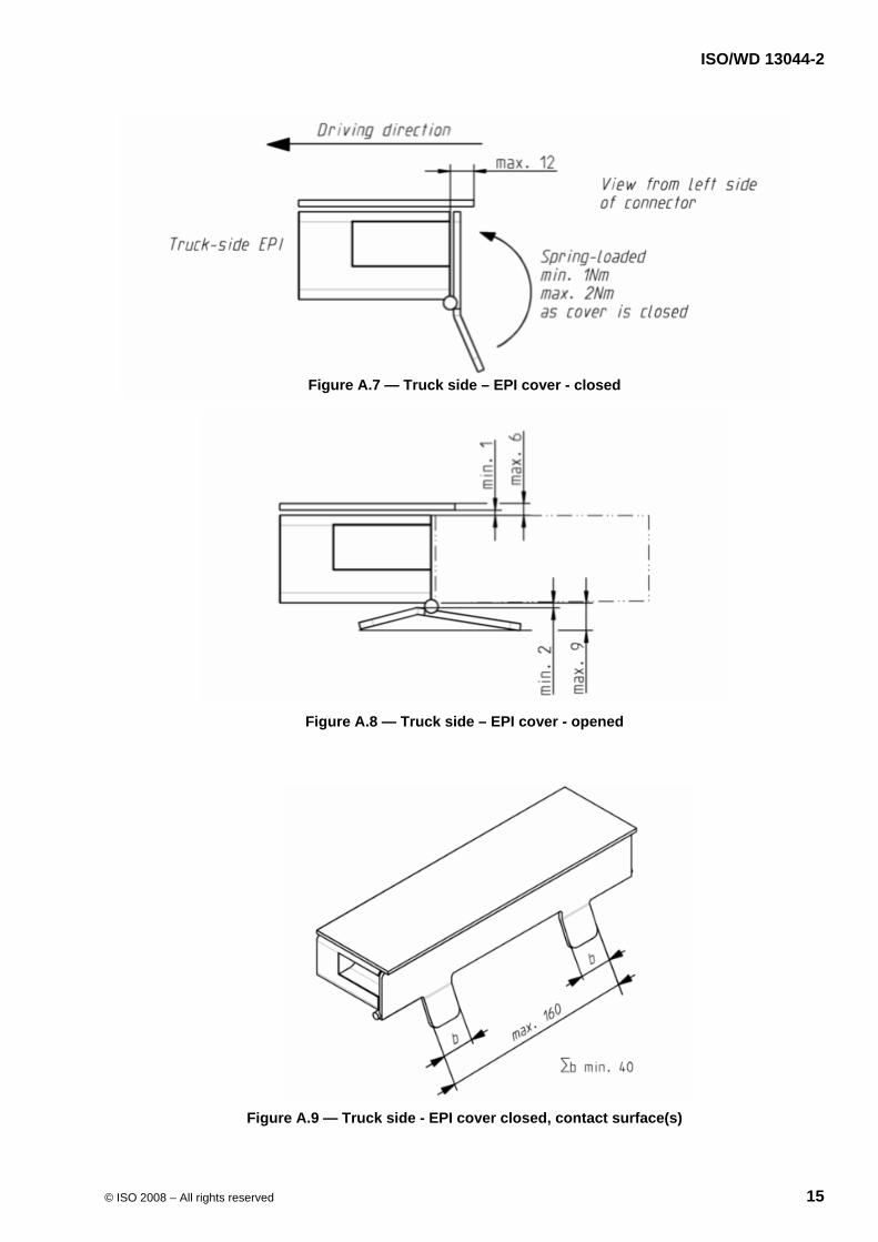
4.6.3.1 Protection cover on truck-EPI
See Annex A, Figure A.7 – A.9 4.6.3.2 Protection cover on trailer-EPI
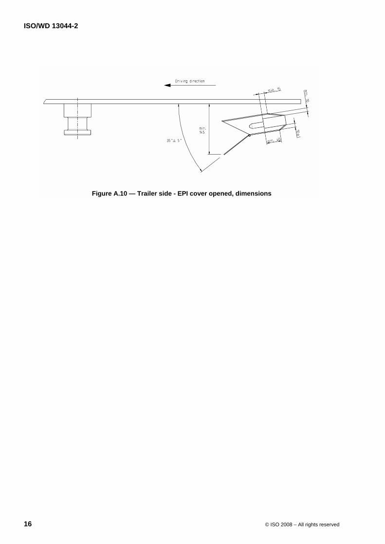
See Annex A, Figure A.10 4.6.3.3 Trailer-side protection actuation Protection cover on trailer shall be open 120mm before king pin reaches coupled position. Protection cover shall try to close latest 50mm before king pin reaches coupled position. Protection cover shall not cause damage to any part while trying to close.
See Annex A, Figure A.1 4.7 Future developments
EPI plug modules and EPI socket modules in accordance with this Standard shall provide additional free space for future extensions – specific allocation to be defined later. The free space reserved shall not be used for other purposes; see Annex A, Figure A.11 and table A1
4.8 Landing legs
If equipped with automated landing legs they shall be power driven without necessarily being able to lift the trailer. In case the automated landing legs were unable to lift the trailer, the rear axle air suspension of towing vehicle is required. Landing legs electrical control unit shall be mounted on truck side.
Information on the height level of the landing legs shall be displayed to the driver.
ISO/WD 13044-2
6 © ISO 2008 – All rights reserved
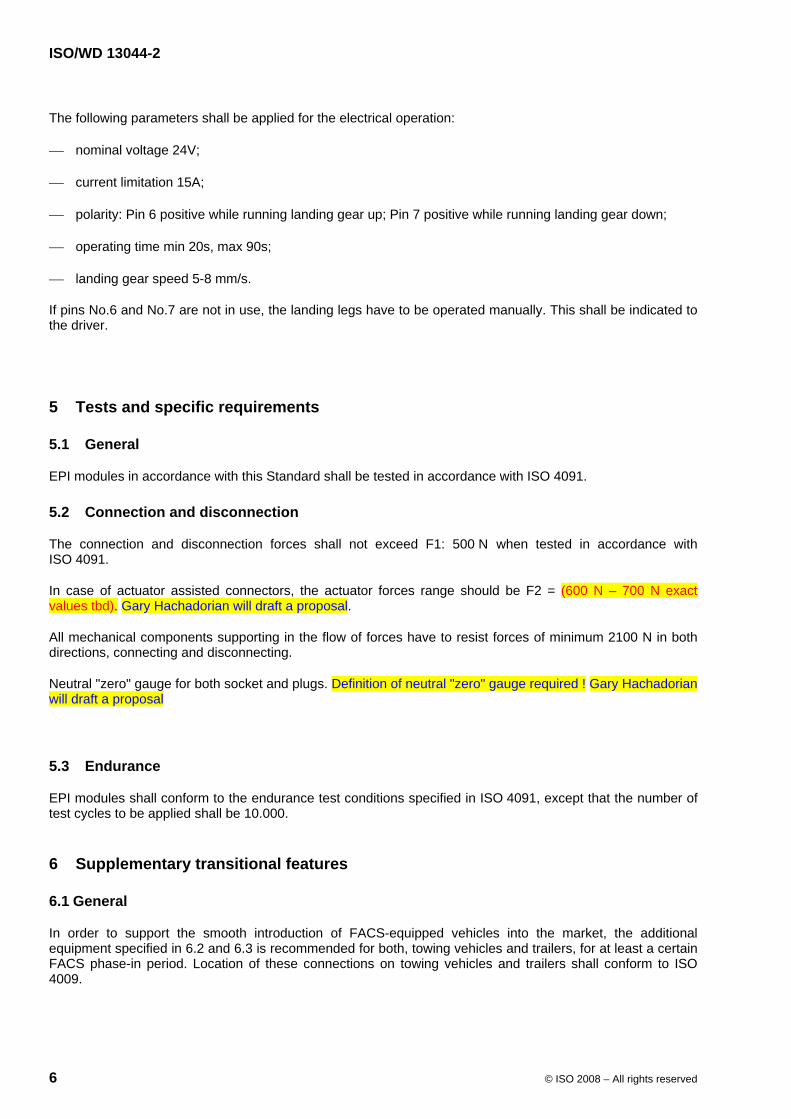
The following parameters shall be applied for the electrical operation:
⎯ nominal voltage 24V;
⎯ current limitation 15A;
⎯ polarity: Pin 6 positive while running landing gear up; Pin 7 positive while running landing gear down;
⎯ operating time min 20s, max 90s;
⎯ landing gear speed 5-8 mm/s.
If pins No.6 and No.7 are not in use, the landing legs have to be operated manually. This shall be indicated to the driver.
5 Tests and specific requirements
5.1 General
EPI modules in accordance with this Standard shall be tested in accordance with ISO 4091.
5.2 Connection and disconnection
The connection and disconnection forces shall not exceed F1: 500 N when tested in accordance with ISO 4091.
In case of actuator assisted connectors, the actuator forces range should be F2 = (600 N – 700 N exact values tbd). Gary Hachadorian will draft a proposal.
All mechanical components supporting in the flow of forces have to resist forces of minimum 2100 N in both directions, connecting and disconnecting.
Neutral "zero" gauge for both socket and plugs. Definition of neutral "zero" gauge required ! Gary Hachadorian will draft a proposal
5.3 Endurance
EPI modules shall conform to the endurance test conditions specified in ISO 4091, except that the number of test cycles to be applied shall be 10.000.
6 Supplementary transitional features
6.1 General
In order to support the smooth introduction of FACS-equipped vehicles into the market, the additional equipment specified in 6.2 and 6.3 is recommended for both, towing vehicles and trailers, for at least a certain FACS phase-in period. Location of these connections on towing vehicles and trailers shall conform to ISO 4009.
ISO/WD 13044-2
© ISO 2008 – All rights reserved 7
6.2 Tractor vehicles
In order to permit FACS-equipped tractor vehicles to be coupled with conventional semi-trailers having no FACS, it is recommended that tractor vehicles in compliance with this Standard are additionally equipped with conventional connectors, such as:
⎯ electrical/electronic connections in accordance with ISO 7638 and ISO 12098;
⎯ pneumatic connections in accordance with ISO 1728.
6.3 Semi-trailers
In order to permit FACS-equipped semi-trailers to be coupled with conventional tractor vehicles having no FACS or in case of emergency (e.g. in case of accident), it is recommended that the semi-trailers in compliance with this Standard are additionally equipped with conventional connectors, such as:
⎯ electrical/electronic connections in accordance with ISO 7638 and ISO 12098;
⎯ pneumatic connections in accordance with ISO 1728.
ISO/WD 13044-2
8 © ISO 2008 – All rights reserved
Annex A (normative)
EPI module - dimensional characteristics
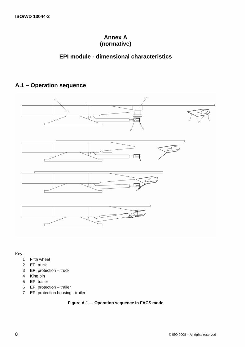
A.1 – Operation sequence
Key: 1 Fifth wheel 2 EPI truck 3 EPI protection – truck 4 King pin 5 EPI trailer 6 EPI protection – trailer 7 EPI protection housing - trailer
Figure A.1 — Operation sequence in FACS mode
ISO/WD 13044-2
© ISO 2008 – All rights reserved 9
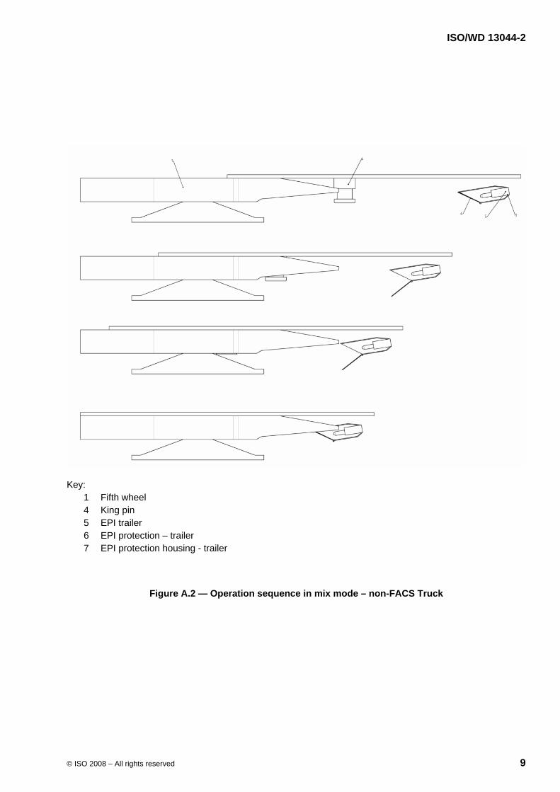
Key: 1 Fifth wheel 4 King pin 5 EPI trailer 6 EPI protection – trailer 7 EPI protection housing - trailer
Figure A.2 — Operation sequence in mix mode – non-FACS Truck

ISO/WD 13044-2
10 © ISO 2008 – All rights reserved
A.2 – EPI characteristics - positions
a) uncoupled
b) coupled
Figure A.3 — Position of the EPI socket module on the fifth wheel
ISO/WD 13044-2
© ISO 2008 – All rights reserved 11
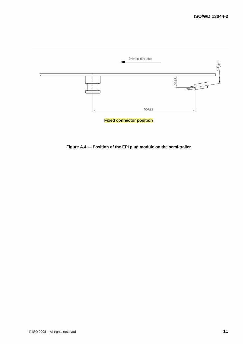
Fixed connector position
Figure A.4 — Position of the EPI plug module on the semi-trailer
ISO/WD 13044-2
12 © ISO 2008 – All rights reserved
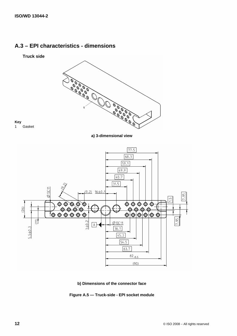
A.3 – EPI characteristics - dimensions
Truck side
Key 1 Gasket
a) 3-dimensional view
b) Dimensions of the connector face
Figure A.5 — Truck-side - EPI socket module
ISO/WD 13044-2
© ISO 2008 – All rights reserved 13
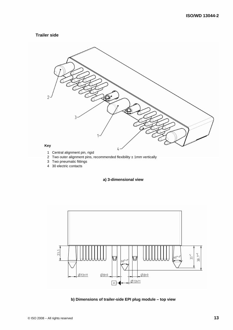
Trailer side
Key
1 Central alignment pin, rigid 2 Two outer alignment pins, recommended flexibility ± 1mm vertically 3 Two pneumatic fittings 4 30 electric contacts
a) 3-dimensional view
b) Dimensions of trailer-side EPI plug module – top view
ISO/WD 13044-2
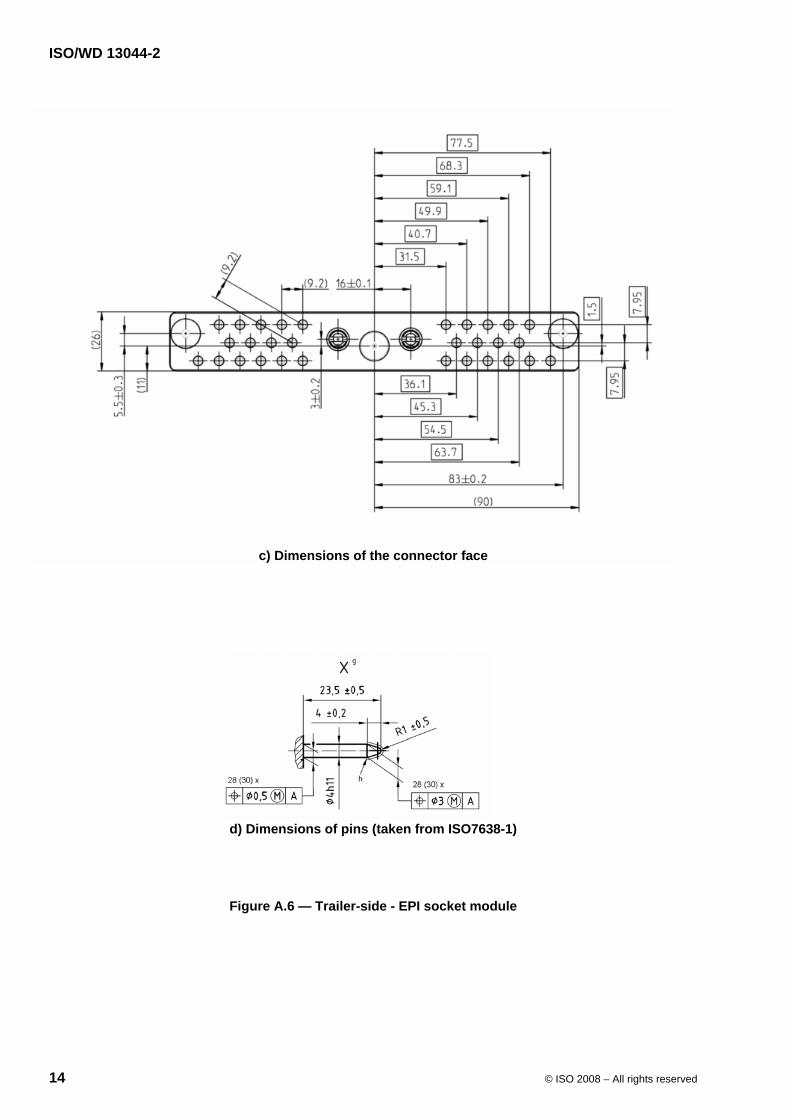
14 © ISO 2008 – All rights reserved
c) Dimensions of the connector face
d) Dimensions of pins (taken from ISO7638-1)
Figure A.6 — Trailer-side - EPI socket module
ISO/WD 13044-2
© ISO 2008 – All rights reserved 15
Figure A.7 — Truck side – EPI cover - closed
Figure A.8 — Truck side – EPI cover - opened
Figure A.9 — Truck side - EPI cover closed, contact surface(s)
ISO/WD 13044-2
16 © ISO 2008 – All rights reserved
Figure A.10 — Trailer side - EPI cover opened, dimensions
ISO/WD 13044-2
© ISO 2008 – All rights reserved 17
Annex B
(normative)
EPI module - contact allocation
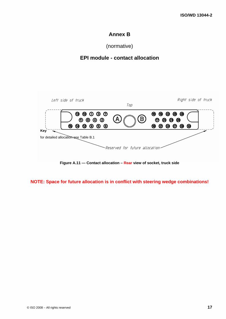
Key
for detailed allocation see Table B.1
Figure A.11 — Contact allocation – Rear view of socket, truck side
NOTE: Space for future allocation is in conflict with steering wedge combinations!
ISO/WD 13044-2
18 © ISO 2008 – All rights reserved
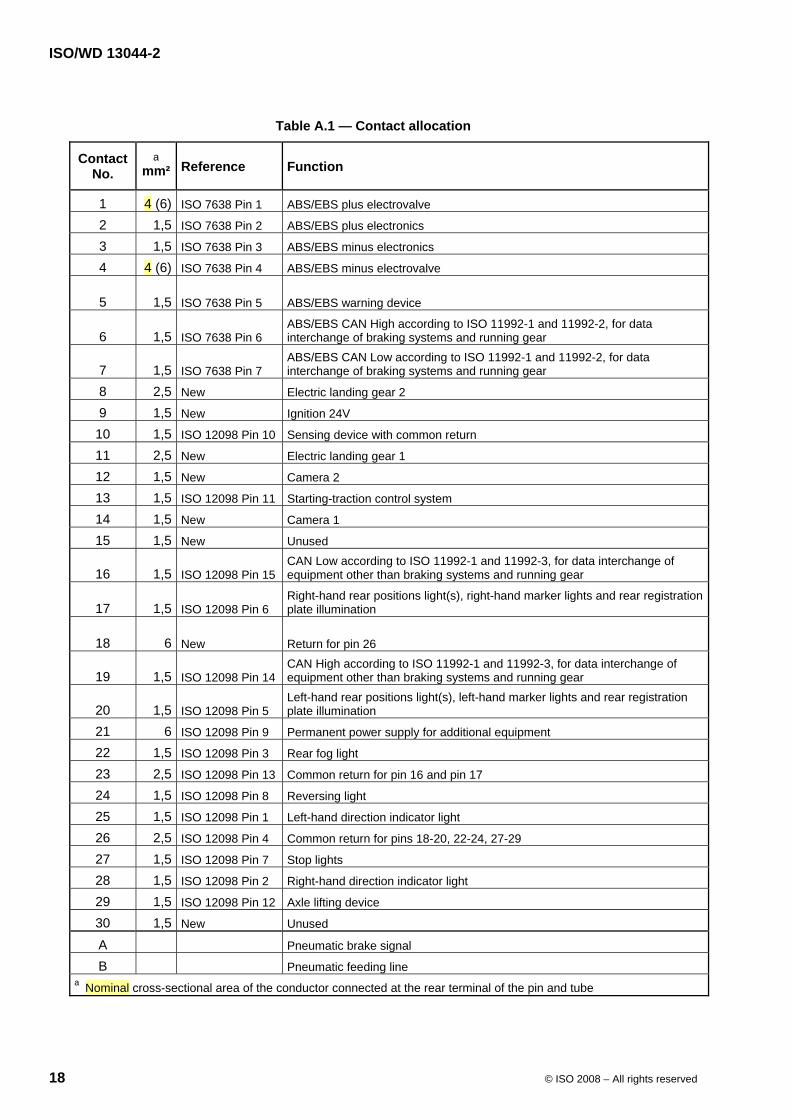
Table A.1 — Contact allocation
Contact No.
a mm² Reference Function
1 4 (6) ISO 7638 Pin 1 ABS/EBS plus electrovalve
2 1,5 ISO 7638 Pin 2 ABS/EBS plus electronics
3 1,5 ISO 7638 Pin 3 ABS/EBS minus electronics
4 4 (6) ISO 7638 Pin 4 ABS/EBS minus electrovalve
5 1,5 ISO 7638 Pin 5 ABS/EBS warning device
6 1,5 ISO 7638 Pin 6 ABS/EBS CAN High according to ISO 11992-1 and 11992-2, for data interchange of braking systems and running gear
7 1,5 ISO 7638 Pin 7 ABS/EBS CAN Low according to ISO 11992-1 and 11992-2, for data interchange of braking systems and running gear
8 2,5 New Electric landing gear 2
9 1,5 New Ignition 24V
10 1,5 ISO 12098 Pin 10 Sensing device with common return
11 2,5 New Electric landing gear 1
12 1,5 New Camera 2
13 1,5 ISO 12098 Pin 11 Starting-traction control system
14 1,5 New Camera 1
15 1,5 New Unused
16 1,5 ISO 12098 Pin 15 CAN Low according to ISO 11992-1 and 11992-3, for data interchange of equipment other than braking systems and running gear
17 1,5 ISO 12098 Pin 6 Right-hand rear positions light(s), right-hand marker lights and rear registration plate illumination
18 6 New Return for pin 26
19 1,5 ISO 12098 Pin 14 CAN High according to ISO 11992-1 and 11992-3, for data interchange of equipment other than braking systems and running gear
20 1,5 ISO 12098 Pin 5 Left-hand rear positions light(s), left-hand marker lights and rear registration plate illumination
21 6 ISO 12098 Pin 9 Permanent power supply for additional equipment
22 1,5 ISO 12098 Pin 3 Rear fog light
23 2,5 ISO 12098 Pin 13 Common return for pin 16 and pin 17
24 1,5 ISO 12098 Pin 8 Reversing light
25 1,5 ISO 12098 Pin 1 Left-hand direction indicator light
26 2,5 ISO 12098 Pin 4 Common return for pins 18-20, 22-24, 27-29
27 1,5 ISO 12098 Pin 7 Stop lights
28 1,5 ISO 12098 Pin 2 Right-hand direction indicator light
29 1,5 ISO 12098 Pin 12 Axle lifting device
30 1,5 New Unused
A Pneumatic brake signal
B Pneumatic feeding line a Nominal cross-sectional area of the conductor connected at the rear terminal of the pin and tube