Embed Size (px)
Citation preview
Mineral insulatedHeating Cables

isoMil -t + M + H
Norbert Baumann
Manfred Böhnke
Walter Wagner
Mil gmbH
World-wide increasing precision, reliability, and safety requirements in Temperature, Control
and Measurement Engineering can no longer be satisfied by conventional cables causing a
rising need for mineral insulated lines. Applications cover everything from the simple build-
ing of furnaces to the production of nuclear power plants.
Our product catalogue will guide you through a selection of state-of-the-art mineral insulated
thermocouples and heating cables. We can offer thereby 35 years of experience.
The close collaboration with leading customers - world-wide - is the guarantor for a broadly
varied offer, with a maximum flexibility and highest reliability. Our head office is in the city of
Hanau, Germany. From here we service our national and international customers.
The MiL GmbH is both a manufacturer and a service provider. We offer to our customers
everything from professional consultation to custom-made products.
Yours sincerely
Norbert Baumann
3
Contents
The MIL GmbH . . . . . . . . . . . . . . . . . . . . . . . . . . . . . . . . . . . . . . . . . . . . . . . . . . . . . . . . . . . . . . . . . . . . . 2
Mi sheathed Heating Cable
300 V Double Conductor . . . . . . . . . . . . . . . . . . . . . . . . . . . . . . . . . . . . . . . . . . . . . . . . . . . . . . . . . . . . 4
600 V Single Conductor . . . . . . . . . . . . . . . . . . . . . . . . . . . . . . . . . . . . . . . . . . . . . . . . . . . . . . . . . . . . . 6
400 V Single Conductor . . . . . . . . . . . . . . . . . . . . . . . . . . . . . . . . . . . . . . . . . . . . . . . . . . . . . . . . . . . . . 8
Mi long line Heat tracing Cable . . . . . . . . . . . . . . . . . . . . . . . . . . . . . . . . . . . . . . . . . . . . . . . . 10
standard Mi sheathed Heating Cable at 800 V . . . . . . . . . . . . . . . . . . . . . . . . . . . . . . . . . 11
isoMil -t + M + H
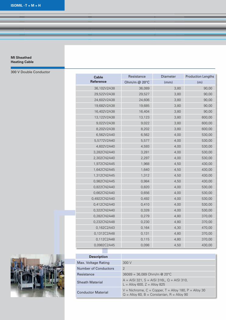
Mi sheathed Heating Cable
300 V Double Conductor
Cable reference
Resistance Diameter Production Lengths
Ohm/m @ 20°C (mm) (m)
36,102V2A38 36,089 3,80 90,00
29,522V2A38 29,527 3,80 90,00
24,602V2A38 24,606 3,80 90,00
19,682V2A38 19,685 3,80 90,00
16,402V2A38 16,404 3,80 90,00
13,122V2A38 13,123 3,80 600,00
9,022V2A38 9,022 3,80 600,00
8,202V2A38 8,202 3,80 600,00
6,562V2A40 6,562 4,00 530,00
5,5772V2A40 5,577 4,00 530,00
4,602V2A40 4,593 4,00 530,00
3,282CN2A40 3,281 4,00 530,00
2,302CN2A40 2,297 4,00 530,00
1,972CN2A45 1,968 4,50 430,00
1,642CN2A45 1,640 4,50 430,00
1,312CN2A45 1,312 4,50 430,00
0,982CN2A45 0,984 4,50 430,00
0,822CN2A40 0,820 4,00 530,00
0,662CN2A40 0,656 4,00 530,00
0,4922CN2A40 0,492 4,00 530,00
0,412CN2A40 0,410 4,00 530,00
0,322CN2A40 0,328 4,00 530,00
0,282CN2A48 0,279 4,80 370,00
0,232CN2A48 0,230 4,80 370,00
0,162C2A43 0,164 4,30 470,00
0,1312C2A48 0,131 4,80 370,00
0,112C2A48 0,115 4,80 370,00
0,0982C2A45 0,098 4,50 430,00
description
Max. Voltage Rating 300 V
Number of Conductors 2
Resistance 36089 = 36,089 Ohm/m @ 20°C
Sheath MaterialA = AISI 321, S = AISI 316L, Q = AISI 310, L = Alloy 600, Z = Alloy 825
Conductor MaterialV = Nichrome, C = Copper, T = Alloy 180, P = Alloy 30Q = Alloy 60, B = Constantan, R = Alloy 90
5
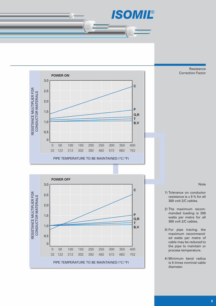
Resistance Correction Factor
Note
1) Tolerance on conductor resistance is ± 5 % for all 300 volt 2/C cables.
2) The maximum recom-mended loading is 200 watts per metre for all 300 volt 2/C cables.
3) For pipe tracing, the maximum recommend-ed watts per metre of cable may be reduced to the pipe to maintain or process temperature.
4) Minimum bend radius is 5 times nominal cable diameter.
Power oFF
3,0
Re
SiS
TaN
Ce
Mu
LTiP
Lie
R F
OR
C
ON
Du
CT
OR
Ma
Te
Ria
LS
C
PQ,rtb,V
2,5
2,0
1,5
1,0
0,5
0
0 50 100 150 200 250 300 350 400
32 122 212 302 392 482 572 662 752
PiPe TeMPeRaTuRe TO Be MaiNTaiNeD (°C / °F)
Power on
3,0
Re
SiS
TaN
Ce
Mu
LTiP
Lie
R F
OR
C
ON
Du
CT
OR
Ma
Te
Ria
LS
C
P
Q,rtb,V
2,5
2,0
1,5
1,0
0,5
0
0 50 100 150 200 250 300 350 400
32 122 212 302 392 482 572 662 752
PiPe TeMPeRaTuRe TO Be MaiNTaiNeD (°C / °F)
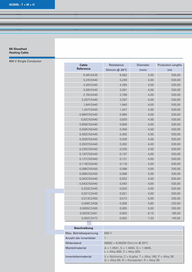
isoMil -t + M + H
600 V Single Conductor
Mi sheathed Heating Cable
Cable reference
Resistance Diameter Production Lengths
Ohm/m @ 20°C (mm) (m)
6,56V2A35 6,562 3,50 200,00
5,24V2A40 5,249 4,00 530,00
4,26V2A40 4,265 4,00 530,00
3,28V2A40 3,281 4,00 530,00
2,78V2A40 2,789 4,00 530,00
2,297V2A40 2,297 4,00 530,00
1,64V2A40 1,640 4,00 530,00
1,247V2A40 1,247 4,00 530,00
0,984CN2A40 0,984 4,00 530,00
0,82CN2A40 0,820 4,00 530,00
0,658CN2A40 0,656 4,00 530,00
0,558CN2A40 0,558 4,00 530,00
0,492CN2A40 0,492 4,00 530,00
0,328CN2A40 0,328 4,00 530,00
0,262CN2A40 0,262 4,00 530,00
0,230CN2A40 0,230 4,00 530,00
0,197CN2A40 0,197 4,00 530,00
0,131CN2A40 0,131 4,00 530,00
0,118CN2A40 0,118 4,00 530,00
0,098CN2A50 0,098 5,00 330,00
0,066CN2A50 0,066 5,00 330,00
0,052CN2A40 0,052 4,00 530,00
0,043CN2A40 0,043 4,00 530,00
0,033C2A40 0,033 4,00 530,00
0,021C2A40 0,021 4,00 530,00
0,013C2A50 0,013 5,00 330,00
0,008C2A58 0,008 5,80 220,00
0,0055C2A50 0,005 5,00 330,00
0,0033C2A61 0,003 6,10 195,00
0,002C2A72 0,002 7,20 140,00
beschreibung
Max. Betriebsspannung 600 V
anzahl der innenleiter 1
Widerstand 06562 = 6,56200 Ohm / m @ 20°C
Mantelmaterial A = 1.4541, S = 1.4404, Q = 1.4845, L = Alloy 600, Z = Alloy 825
innenleitermaterial V = Nichrome, C = Kupfer, T = Alloy 180, P = Alloy 30 Q = Alloy 60, B = Konstantan, R = Alloy 90

7
Resistance Correction Factor
Note
1) Tolerance on conductor resistance is ± 5 % for all 600 Volt 1/C cables.
2) The maximum recom-mended loading is 210 watts per metre for all 600 volt 1/C cables.
3) For pipe tracing, the maximum recommend-ed watts per metre of cable may be reduced to the pipe to maintain or process temperature.
4) Minimum bend radius is 5 times nominal cable diameter.
Power oFF
3,0
Re
SiS
TaN
Ce
Mu
LTiP
Lie
R F
OR
C
ON
Du
CT
OR
Ma
Te
Ria
LS
C
PQ,rtb,V
2,5
2,0
1,5
1,0
0,5
0
0 50 100 150 200 250 300 350 400
32 122 212 302 392 482 572 662 752
PiPe TeMPeRaTuRe TO Be MaiNTaiNeD (°C / °F)
Power on
3,0
Re
SiS
TaN
Ce
Mu
LTiP
Lie
R F
OR
C
ON
Du
CT
OR
Ma
Te
Ria
LS
C
P
Q,rtb,V
2,5
2,0
1,5
1,0
0,5
0
0 50 100 150 200 250 300 350 400
32 122 212 302 392 482 572 662 752
PiPe TeMPeRaTuRe TO Be MaiNTaiNeD (°C / °F)
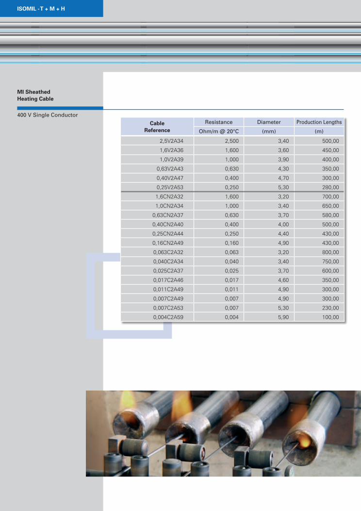
isoMil -t + M + H
400 V Single Conductor
Mi sheathed Heating Cable
Cable reference
Resistance Diameter Production Lengths
Ohm/m @ 20°C (mm) (m)
2,5V2A34 2,500 3,40 500,00
1,6V2A36 1,600 3,60 450,00
1,0V2A39 1,000 3,90 400,00
0,63V2A43 0,630 4,30 350,00
0,40V2A47 0,400 4,70 300,00
0,25V2A53 0,250 5,30 280,00
1,6CN2A32 1,600 3,20 700,00
1,0CN2A34 1,000 3,40 650,00
0,63CN2A37 0,630 3,70 580,00
0,40CN2A40 0,400 4,00 500,00
0,25CN2A44 0,250 4,40 430,00
0,16CN2A49 0,160 4,90 430,00
0,063C2A32 0,063 3,20 800,00
0,040C2A34 0,040 3,40 750,00
0,025C2A37 0,025 3,70 600,00
0,017C2A46 0,017 4,60 350,00
0,011C2A49 0,011 4,90 300,00
0,007C2A49 0,007 4,90 300,00
0,007C2A53 0,007 5,30 230,00
0,004C2A59 0,004 5,90 100,00
9
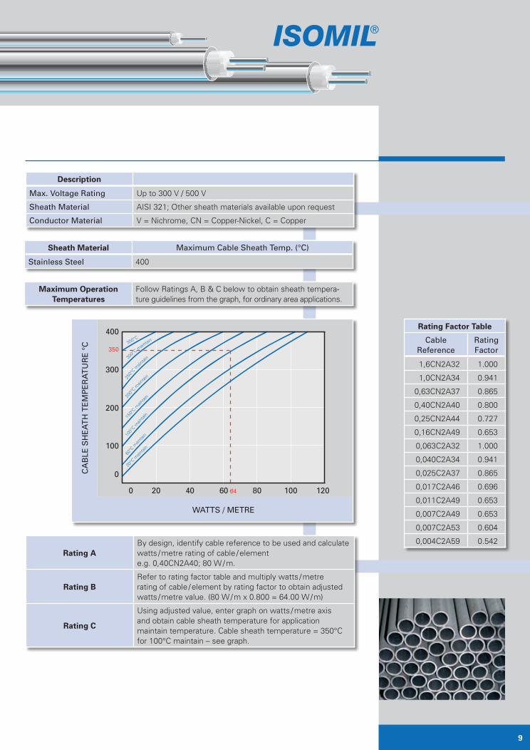
description
Max. Voltage Rating Up to 300 V / 500 V
Sheath Material AISI 321; Other sheath materials available upon request
Conductor Material V = Nichrome, CN = Copper-Nickel, C = Copper
sheath Material Maximum Cable Sheath Temp. (°C)
Stainless Steel 400
rating aBy design, identify cable reference to be used and calculatewatts / metre rating of cable / element e.g. 0,40CN2A40; 80 W / m.
rating bRefer to rating factor table and multiply watts / metre rating of cable / element by rating factor to obtain adjusted watts / metre value. (80 W / m x 0.800 = 64.00 W / m)
rating C
Using adjusted value, enter graph on watts / metre axis and obtain cable sheath temperature for application maintain temperature. Cable sheath temperature = 350°C for 100°C maintain – see graph.
Maximum operation temperatures
Follow Ratings A, B & C below to obtain sheath tempera-ture guidelines from the graph, for ordinary area applications.
rating Factor table
Cable Reference
Rating Factor
1,6CN2A32 1.000
1,0CN2A34 0.941
0,63CN2A37 0.865
0,40CN2A40 0.800
0,25CN2A44 0.727
0,16CN2A49 0.653
0,063C2A32 1.000
0,040C2A34 0.941
0,025C2A37 0.865
0,017C2A46 0.696
0,011C2A49 0.653
0,007C2A49 0.653
0,007C2A53 0.604
0,004C2A59 0.542
Ca
BLe
SH
ea
TH
Te
MP
eR
aT
uR
e °
C
400
350
300
200
100
0
0 20 40 60 64 80 100 120
WaTTS / MeTRe
350°C
300°C
main
tain
250°
C m
aintai
n
200°
C m
aintai
n
15
0°C m
ain
tain
100°
C main
tain
60°C
main
tain
20°C
main
tain
isoMil -t + M + H
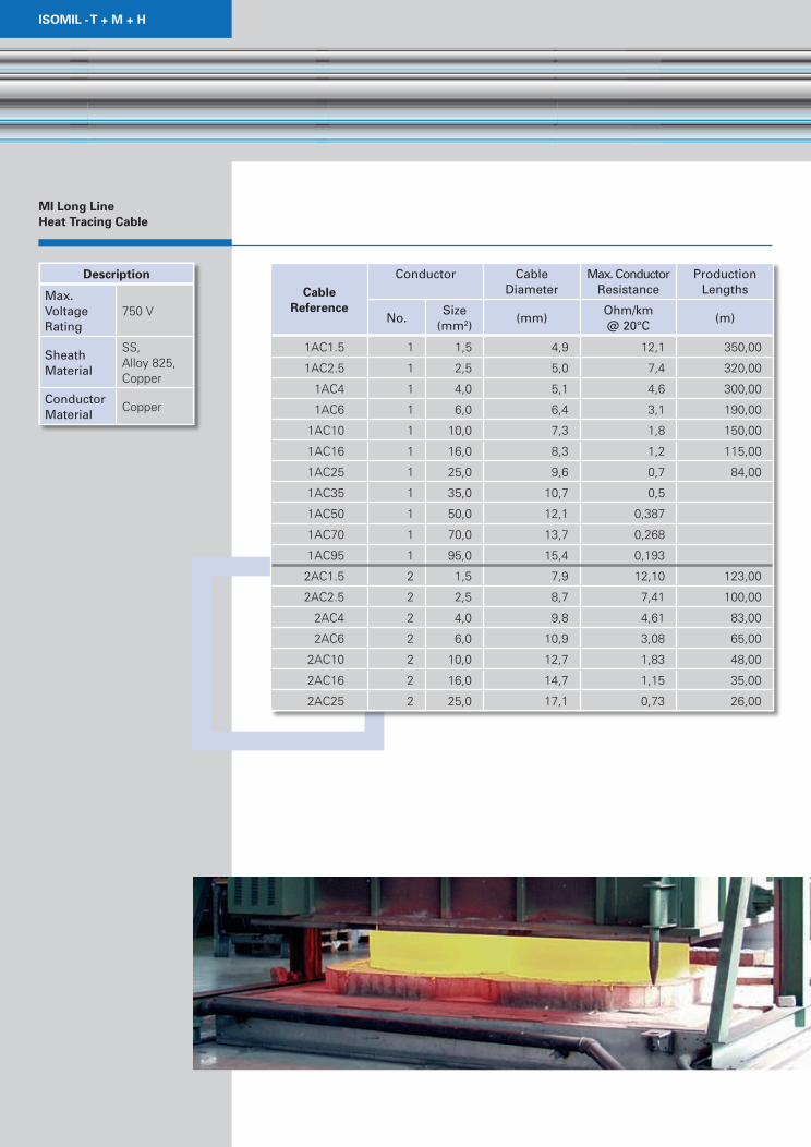
Mi long line Heat tracing Cable
Cable reference
Conductor Cable Diameter
Max. Conductor Resistance
Production Lengths
No.Size
(mm2)(mm)
Ohm/km @ 20°C
(m)
1AC1.5 1 1,5 4,9 12,1 350,00
1AC2.5 1 2,5 5,0 7,4 320,00
1AC4 1 4,0 5,1 4,6 300,00
1AC6 1 6,0 6,4 3,1 190,00
1AC10 1 10,0 7,3 1,8 150,00
1AC16 1 16,0 8,3 1,2 115,00
1AC25 1 25,0 9,6 0,7 84,00
1AC35 1 35,0 10,7 0,5
1AC50 1 50,0 12,1 0,387
1AC70 1 70,0 13,7 0,268
1AC95 1 95,0 15,4 0,193
2AC1.5 2 1,5 7,9 12,10 123,00
2AC2.5 2 2,5 8,7 7,41 100,00
2AC4 2 4,0 9,8 4,61 83,00
2AC6 2 6,0 10,9 3,08 65,00
2AC10 2 10,0 12,7 1,83 48,00
2AC16 2 16,0 14,7 1,15 35,00
2AC25 2 25,0 17,1 0,73 26,00
description
Max. Voltage Rating
750 V
Sheath Material
SS, Alloy 825, Copper
Conductor Material
Copper
11
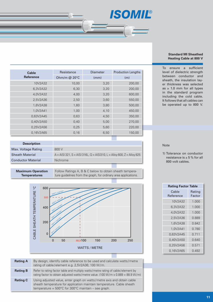
To ensure a sufficient level of dielectric strength between conductor and sheath, the insulation lay-er thickness was selected as ≥ 1.0 mm for all types in the standard program including the cold cable. it follows that all cables can be operated up to 800 V.
Note 1) Tolerance on conductor
resistance is ± 5 % for all 800 volt cables.
standard Mi sheathed Heating Cable at 800 V
Cable reference
Resistance Diameter Production Lengths
Ohm/m @ 20°C (mm) (m)
10V2A32 10,00 3,20 200,00
6,3V2A32 6,30 3,20 200,00
4,0V2A32 4,00 3,20 600,00
2,5V2A36 2,50 3,60 550,00
1,6V2A38 1,60 3,80 500,00
1,0V2A41 1,00 4,10 450,00
0,63V2A45 0,63 4,50 350,00
0,40V2A50 0,40 5,00 270,00
0,25V2A56 0,25 5,60 220,00
0,16V2A65 0,16 6,50 150,00
description
Max. Voltage Rating 800 V
Sheath Material A = AISI 321, S = AISI 316L, Q = AISI310, L = Alloy 600, Z = Alloy 825
Conductor Material Nichrome
rating a By design, identify cable reference to be used and calculate watts / metre rating of cable / element e.g. 2,5V2A36; 100 W / m.
rating b Refer to rating factor table and multiply watts / metre rating of cable / element by rating factor to obtain adjusted watts / metre value. (100 W / m x 0.889 = 88.9 W / m)
rating C Using adjusted value, enter graph on watts / metre axis and obtain cable sheath temperature for application maintain temperature. Cable sheath temperature = 500°C for 300°C maintain – see graph.
Maximum operation temperatures
Follow Ratings A, B & C below to obtain sheath tempera-ture guidelines from the graph, for ordinary area applications.
rating Factor table
Cable Reference
Rating Factor
10V2A32 1.000
6,3V2A32 1.000
4,0V2A32 1.000
2,5V2A36 0.889
1,6V2A38 0.842
1,0V2A41 0.780
0,63V2A45 0.711
0,40V2A50 0.640
0,25V2A56 0.571
0,16V2A65 0.492
Ca
BLe
SH
ea
TH
Te
MP
eR
aT
uR
e °
C 600
500
400
200
0
0 50 88,9100 150 200 250
WaTTS / MeTRe
400°C maintain
500°C maintain
300°C m
aintain
20°C
main
tain
200°C m
aintai
n
100°
C main
tain
Mineral insulated
Heating Cables
Mil gmbH
Industriepark Hanau • Halle 4
Ehrichstraße 10 • 63450 Hanau
Tel. +49 (0) 61 81 - 93 15 50
Fax +49 (0) 61 81 - 31 71 0
e-mail [email protected]
internet www.isomil.de
How to Find us
a3 Frankfurt
Direction: München / Würzburg / Hanau
Next: Direction B45 Hanau
Next: Direction B43a Fulda
Exit: Hanau - Hafen
a45 giessen
Direction: Hanauer Kreuz
(Motorway intersection Hanau)
Next: Direction B43a Dieburg
Exit: Hanau - Hafen
now
Turn right, direction Hanau - Hafen.
Then left, direction Industriegebiet (Industrial area)
Hafenstraße.
Next right, Ehrichstraße 10, Industriepark Gebäude 4
(Industrial park, Building No. 4) on the left.


![TECHNICAL HANDBOOK - nVent · 2019-12-20 · Heating cable length (m) = (Heating cable length m) B. Stairs Heating cable length (m) = [2 x stair width m) + 0.4] x number of stairs](https://img.pdfslide.us/doc/110x75/5f2ef73fc7c5162cd835d9b1/technical-handbook-nvent-2019-12-20-heating-cable-length-m-heating-cable.jpg)