Embed Size (px)
Citation preview
Catalogue CAT-DX-2AU
Pneumatic
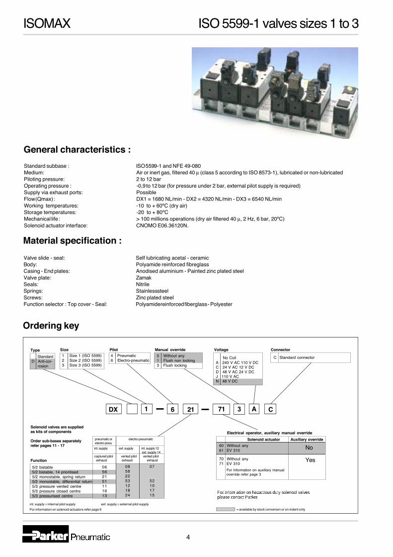
ISOMAXISOMAXDirectional control valves
According to ISO 5599-1
1
ISOMAX Summary
contents
ISO 5599-1 valves sizes 1 to 3Features.............................................................................2-3Ordering information - valves............................................4-5General technical information................................................4Flow ratings...........................................................................6 Response times.....................................................................6In-rush and holding currents................................................6Spare parts...........................................................................6LOGISO interface logic elements.........................................7Dimensions - valves..............................................................8Ordering information - subbases and manifolds............9-12Dimensions - subbases and manifolds...........................13-16
2
ISOMAX ISO valves sizes 1 to 3
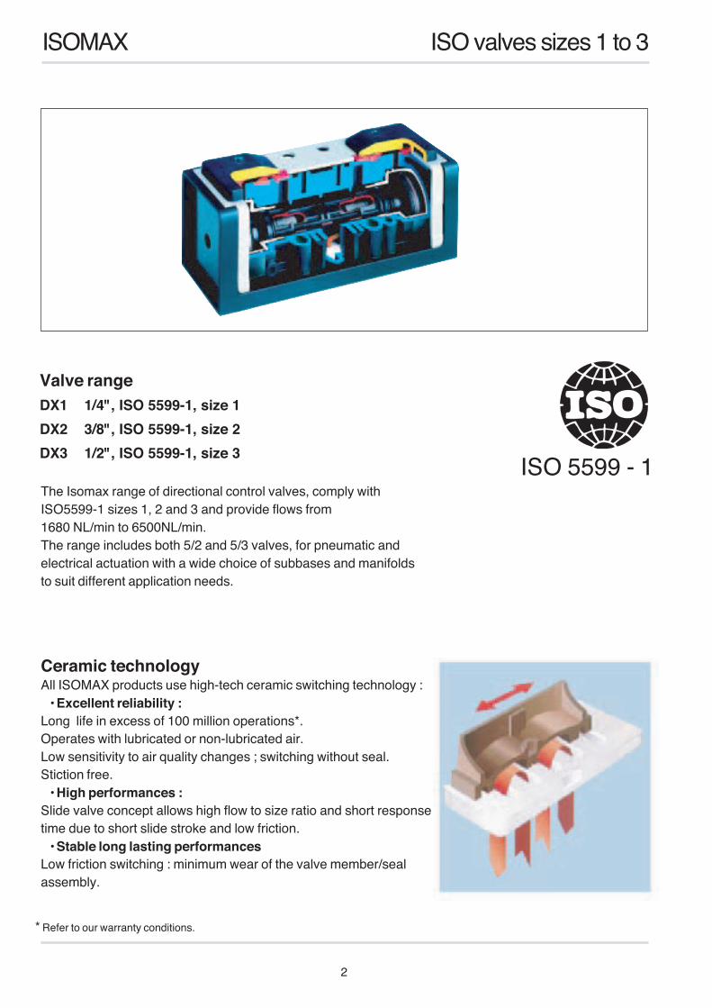
Ceramic technologyAll ISOMAX products use high-tech ceramic switching technology :
• Excellent reliability :Long life in excess of 100 million operations*.Operates with lubricated or non-lubricated air.Low sensitivity to air quality changes ; switching without seal.Stiction free.
• High performances :Slide valve concept allows high flow to size ratio and short responsetime due to short slide stroke and low friction.
• Stable long lasting performancesLow friction switching : minimum wear of the valve member/sealassembly.
The Isomax range of directional control valves, comply withISO5599-1 sizes 1, 2 and 3 and provide flows from1680 NL/min to 6500NL/min.The range includes both 5/2 and 5/3 valves, for pneumatic andelectrical actuation with a wide choice of subbases and manifoldsto suit different application needs.
ISO 5599 - 1
* Refer to our warranty conditions.
Valve rangeDX1 1/4", ISO 5599-1, size 1DX2 3/8", ISO 5599-1, size 2DX3 1/2", ISO 5599-1, size 3
3
ISOMAX ISO valves sizes 1 to 3
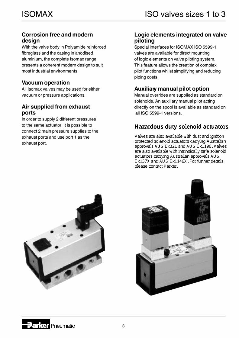
Corrosion free and moderndesignWith the valve body in Polyamide reinforcedfibreglass and the casing in anodisedaluminium, the complete Isomax rangepresents a coherent modern design to suitmost industrial environments.
Vacuum operationAll Isomax valves may be used for eithervacuum or pressure applications.
Air supplied from exhaustportsIn order to supply 2 different pressuresto the same actuator, it is possible toconnect 2 main pressure supplies to theexhaust ports and use port 1 as theexhaust port.
Logic elements integrated on valvepilotingSpecial interfaces for ISOMAX ISO 5599-1valves are available for direct mountingof logic elements on valve piloting system.This feature allows the creation of complexpilot functions whilst simplifying and reducingpiping costs.
Auxiliary man ual pilot optionManual overrides are supplied as standard onsolenoids. An auxiliary manual pilot actingdirectly on the spool is available as standard on all ISO 5599-1 versions.
4
ISOMAX ISO 5599-1 valves sizes 1 to 3
Standard subbase : ISO 5599-1 and NFE 49-080Medium: Air or inert gas, filtered 40 µ (class 5 according to ISO 8573-1), lubricated or non-lubricatedPiloting pressure: 2 to 12 barOperating pressure : -0,9 to 12 bar (for pressure under 2 bar, external pilot supply is required)Supply via exhaust ports: PossibleFlow (Qmax) : DX1 = 1680 NL/min - DX2 = 4320 NL/min - DX3 = 6540 NL/minWorking temperatures: -10 to + 60ºC (dry air)Storage temperatures: -20 to + 80ºC Mechanical life : > 100 millions operations (dry air filtered 40 µ, 2 Hz, 6 bar, 20ºC)Solenoid actuator interface: CNOMO E06.36120N.
General characteristics :
Valve slide - seat: Self lubricating acetal - ceramic Body: Polyamide reinforced fibreglassCasing - End plates: Anodised aluminium - Painted zinc plated steelValve plate: ZamakSeals: NitrileSprings: Stainless steelScrews: Zinc plated steelFunction selector : Top cover - Seal: Polyamide reinforced fiberglass - Polyester
Material specification :
Ordering key
1 Size 1 (ISO 5599)2 Size 2 (ISO 5599)3 Size 3 (ISO 5599)
4 Pneumatic6 Electro-pneumatic
0 Without any1 Flush non locking3 Flush locking
5/2 bistable5/2 bistable, 14 prioritised5/2 monostable, spring return5/2 monostable, differential return5/3 pressure vented centre5/3 pressure closed centre5/3 pressurised centre
C Standard connector
pneumatic or electro-pneumaticelectro-pneu int. supply ext. supply int. supply 12 ext. supply 14 captured pilot vented pilot vented pilot exhaust exhaust exhaust
06562151111613
08582253121824
07
52101715
No CoilA 240 V AC 110 V DCC 24 V AC 12 V DCD 48 V AC 24 V DCJ 110 V ACN 48 V DC
Solenoid actuator Auxiliary override60 Without any61 EV 310
70 Without any71 EV 310
For information on auxiliary manualoverride refer page 3
DX 6 21 71 3 A C
Size Pilot Manual override Voltage Connector
Electrical operator, auxiliary manual override
Function
Solenoid valves are suppliedas kits of components
Order sub-bases separatelyrefer pages 11 - 17
= available by stock converson or on indent onlyint. supply = internal pilot supply ext. supply = external pilot supplyFor information on solenoid actuators refer page 6
StandardD Anti-cor- rosion
Type
No
Yes
1

5
ISOMAX ISO 5599-1 valves sizes 1 to 3
Symbol Function ISO 5599-1 size Order code Weightkg
5/2 Bistable 1 DX1-406-70 0,35 2 DX2-406-70 0,60 3 DX3-406-70 1,105/2 Monostable 1 DX1-451-70 0,35differential 2 DX2-451-70 0,60 3 DX3-451-70 1,105/2 Monostable 1 DX1-421-70 0,35spring 2 DX2-421-70 0,60 3 DX3-421-70 1,105/3 1 DX1-416-70 0,35closed centre 2 DX2-416-70 0,60 3 DX3-416-70 1,105/3 1 DX1-411-70 0,35vented centre 2 DX2-411-70 0,60 3 DX3-411-70 1,105/3 1 DX1-413-70 0,35pressurised centre 2 DX2-413-70 0,60
Order codes
Pneumatically actuated valves
Electrically actuated valve kits. Refer page 6 for complete order codes
* = Solenoid valve weights include coils** = Refer page 4 for complete order codeSolenoid valves are supplied as kits of componentsOrder sub-bases separately. Refer pages 11 - 17
Symbol Function ISO 5599-1 size Order code Weightkg
Bistable 1 DX1-606** 0,69 2 DX2-606** 0,94 3 DX3-606** 1,445/2 Monostable 1 DX1-651** 0,52differential 2 DX2-651** 0,77 3 DX3-651** 1,275/2 Monostable 1 DX1-621** 0,52spring 2 DX2-621** 0,77 3 DX3-621** 1,275/3 1 DX1-616** 0,69closed centre 2 DX2-616** 0,94 3 DX3-616** 1,445/3 1 DX1-611** 0,69vented centre 2 DX2-611** 0,94 3 DX3-611** 1,445/3 1 DX1-613** 0,69pressurised centre 2 DX2-613** 0,94
= available by stock conversion or on indent only
6
ISOMAX ISO 5599-1 valves sizes 1 to 3
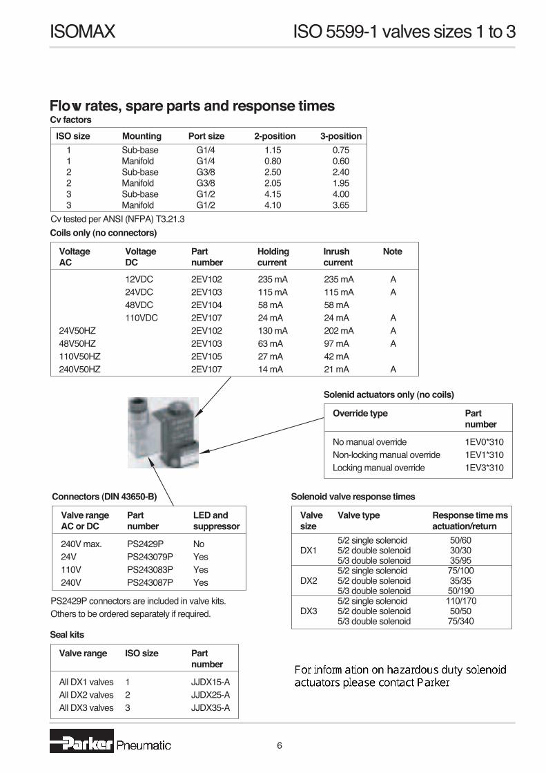
Flow rates, spare parts and response times
Seal kits
Cv factors
Valve range ISO size Part number
All DX1 valves 1 JJDX15-AAll DX2 valves 2 JJDX25-AAll DX3 valves 3 JJDX35-A
Solenid actuators only (no coils)
Override type Part number
No manual override 1EV0*310Non-locking manual override 1EV1*310Locking manual override 1EV3*310
Connectors (DIN 43650-B)
Valve range Part LED andAC or DC number suppressor
240V max. PS2429P No24V PS243079P Yes110V PS243083P Yes240V PS243087P Yes
1 Sub-base G1/4 1.15 0.751 Manifold G1/4 0.80 0.602 Sub-base G3/8 2.50 2.402 Manifold G3/8 2.05 1.953 Sub-base G1/2 4.15 4.003 Manifold G1/2 4.10 3.65
Solenoid valve response times
Valve Valve type Response time mssize actuation/return 5/2 single solenoid 50/60DX1 5/2 double solenoid 30/30 5/3 double solenoid 35/95 5/2 single solenoid 75/100DX2 5/2 double solenoid 35/35 5/3 double solenoid 50/190 5/2 single solenoid 110/170DX3 5/2 double solenoid 50/50 5/3 double solenoid 75/340
Coils only (no connectors)
Voltage Voltage Part Holding Inrush NoteAC DC number current current
12VDC 2EV102 24VDC 2EV103 48VDC 2EV104 110VDC 2EV10724V50HZ 2EV10248V50HZ 2EV103110V50HZ 2EV105240V50HZ 2EV107
235 mA 235 mA A115 mA 115 mA A58 mA 58 mA 24 mA 24 mA A130 mA 202 mA A 63 mA 97 mA A27 mA 42 mA14 mA 21 mA A
Cv tested per ANSI (NFPA) T3.21.3
PS2429P connectors are included in valve kits.Others to be ordered separately if required.
ISO size Mounting Port size 2-position 3-position
7
ISOMAX ISO 5599-1 valves sizes 1 to 3
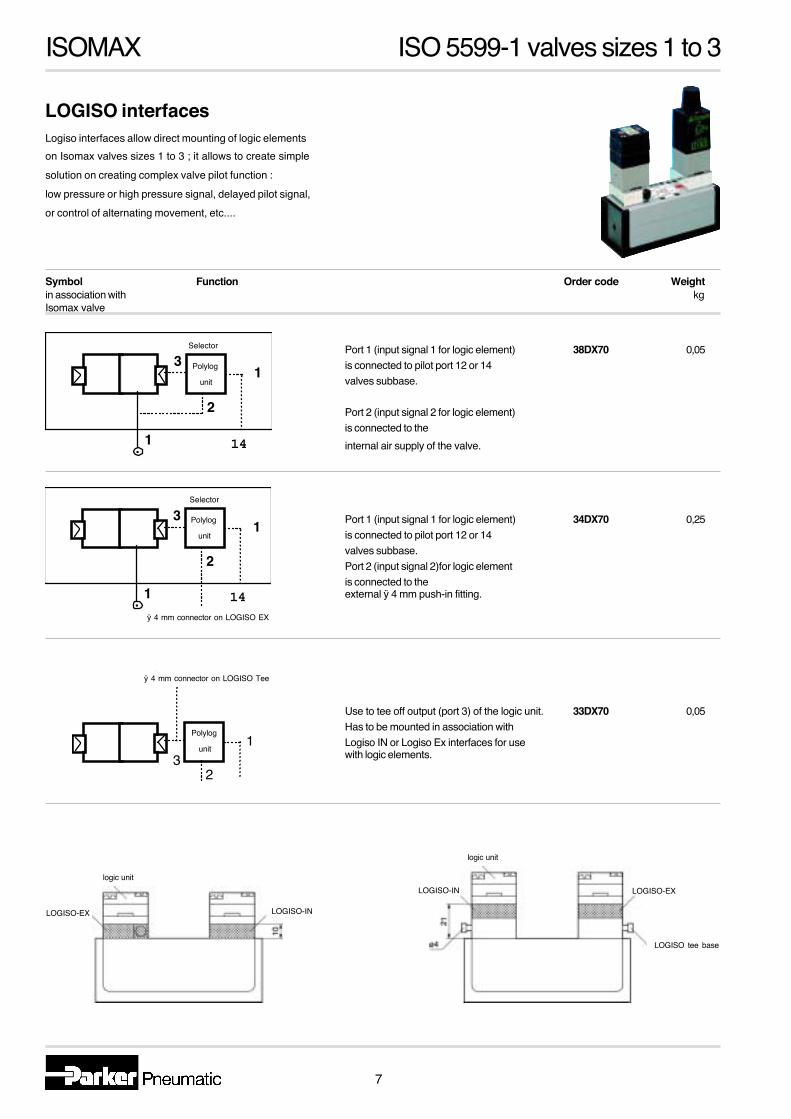
Logiso interfaces allow direct mounting of logic elementson Isomax valves sizes 1 to 3 ; it allows to create simplesolution on creating complex valve pilot function :low pressure or high pressure signal, delayed pilot signal,or control of alternating movement, etc....
LOGISO interfaces
Symbol Function Order code Weightin association with kgIsomax valve
Port 1 (input signal 1 for logic element) 38DX70 0,05is connected to pilot port 12 or 14valves subbase.
Port 2 (input signal 2 for logic element)is connected to theinternal air supply of the valve.
Port 1 (input signal 1 for logic element) 34DX70 0,25is connected to pilot port 12 or 14valves subbase.Port 2 (input signal 2)for logic elementis connected to theexternal ÿ 4 mm push-in fitting.
Use to tee off output (port 3) of the logic unit. 33DX70 0,05Has to be mounted in association withLogiso IN or Logiso Ex interfaces for usewith logic elements.
LOGISO-EX
logic unit
logic unit
LOGISO-IN
LOGISO tee base
1
2
31
14 .
SÈlecteur / Selec
Module
Polylog u
LOGISO-EX
LOGISO-IN
1
2
31
14 .
SÈlecteur / Select
Module Polylog
Polilog u
Orifice ÿ 4 LOGISO EXÿ 4 Connector on LOGISO
23
1
Orifice ÿ 4 plaquette de piÿ 4 Connector on LOGISO Tee
Module Polylog
Polilog un
ÿ 4 mm connector on LOGISO Tee
ÿ 4 mm connector on LOGISO EX
Polylog
unit
Polylog
unit
Selector
Selector
Polylog
unit
LOGISO-IN
8
ISOMAX ISO 5599-1 valves sizes 1 to 3
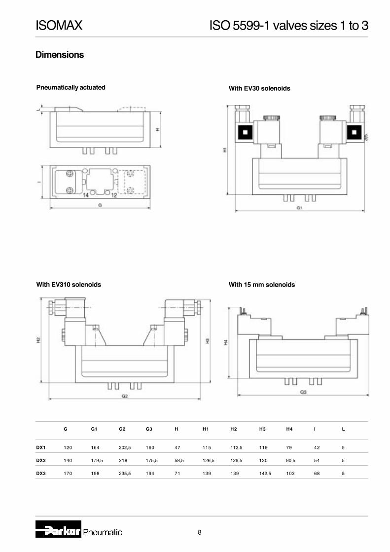
Dimensions
Pneumatically actuated With EV30 solenoids
With EV310 solenoids With 15 mm solenoids
G G1 G2 G3 H H1 H2 H3 H4 I L
DX1 120 164 202,5 160 47 115 112,5 119 79 42 5
DX2 140 179,5 218 175,5 58,5 126,5 126,5 130 90,5 54 5
DX3 170 198 235,5 194 71 139 139 142,5 103 68 5
�
1
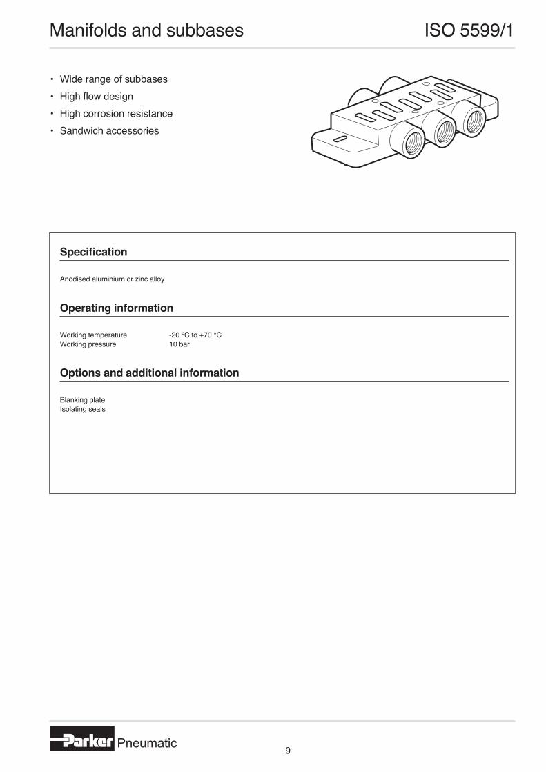
• Wide range of subbases• High flow design • High corrosion resistance• Sandwich accessories
Manifolds and subbases ISO 5599/1
Specification
Operating information
Options and additional information
Anodised aluminium or zinc alloy
Working temperature -20 °C to +70 °CWorking pressure 10 bar
Blanking plateIsolating seals
Pneumatic9

2 3
Size 1
Manifolds and subbases ISO 5599/1
Description Connection Port size Material Weight Order code Dimensions Kg on page o
Single subbases, ISO size 1 Subbase Side G1/8 Zn 0,31 P2N-GS511SD 24
Subbase Side G1/4 Zn 0,29 P2N-GS512SD 24
Subbase, VDMA Side G1/4 Al P2N-VS512SD 24 Subbase, low profile Side G1/4 Al P2N-AS512SD 23 Subbase Bottom G1/4 Zn 0,29 P2N-GS512SB 24
Manifolds, ISO size 1 Manifold Side G1/4 Zn P2N-EM512MD 26
End plate kit Side G3/8 Zn 0,29 P2N-EM513ES 26
Manifold, Bottom G1/4 Al P2N-VM512MB 23 VDMA 24345 form C
End plate kit, Side G3/8 Al P2N-VM513E 23 VDMA 24345 form D Manifold, low profile Bottom G1/4 Al P2N-AM512MB 23
End feed, low profile Side G3/8 Al P2N-AM513GS 23
End feed, low profile Top or bottom G3/8 Al P2N-AM513GT 23
Intermediate feed, low profile Top or bottom G3/8 Al P2N-AM513BT 23
Isolating seal - - P2N-AK0P For use with low profile type manifold End plate - - P2N-AM500J 23 For use with low profile type manifold Adaptor plate kit, ISO 1 to ISO 2 - - Al P2N-EM500AG 26 includes one adaptor and two end plates Adaptor plate, ISO 1 to ISO 3 - - Al P2N-VM500AK P2N-VM512MB and P2N-YM514MB
= At the time of printing, available on indent only Al = Aluminium alloyZn = Zinc alloy
Pneumatic10
2 3
Size 2
Size 1Manifolds and subbases ISO 5599/1
Description Connection Port size Material Weight Order code Dimensions Kg on page
Accessories, ISO size 1 Blanking plate - - Al P2N-AA5B
Sandwich, flow control Al P2N-GA5F
Sandwich, single regulator - - Al P2N-GA5RG
Sandwich, double regulator - - Al P2N-GA5DG
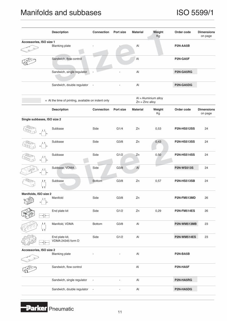
Description Connection Port size Material Weight Order code Dimensions Kg on page
Single subbases, ISO size 2
Subbase Side G1/4 Zn 0,53 P2N-HS512SS 24
Subbase Side G3/8 Zn 0,43 P2N-HS513SS 24
Subbase Side G1/2 Zn 0,50 P2N-HS514SS 24
Subbase, VDMA Side G3/8 Al P2N-WS513S 24 Subbase Bottom G3/8 Zn 0,57 P2N-HS513SB 24
Manifolds, ISO size 2 Manifold Side G3/8 Zn P2N-FM513MD 26
End plate kit Side G1/2 Zn 0,29 P2N-FM514ES 26
Manifold, VDMA Bottom G3/8 Al P2N-WM513MB 23
End plate kit, Side G1/2 Al P2N-WM514ES 23 VDMA 24345 form D
Accessories, ISO size 2 Blanking plate - - Al P2N-BA5B
Sandwich, flow control Al P2N-HA5F
Sandwich, single regulator - - Al P2N-HA5RG
Sandwich, double regulator - - Al P2N-HA5DG
= At the time of printing, available on indent onlyAl = Aluminium alloyZn = Zinc alloy
Pneumatic11
4 5
Size 3
Size 4
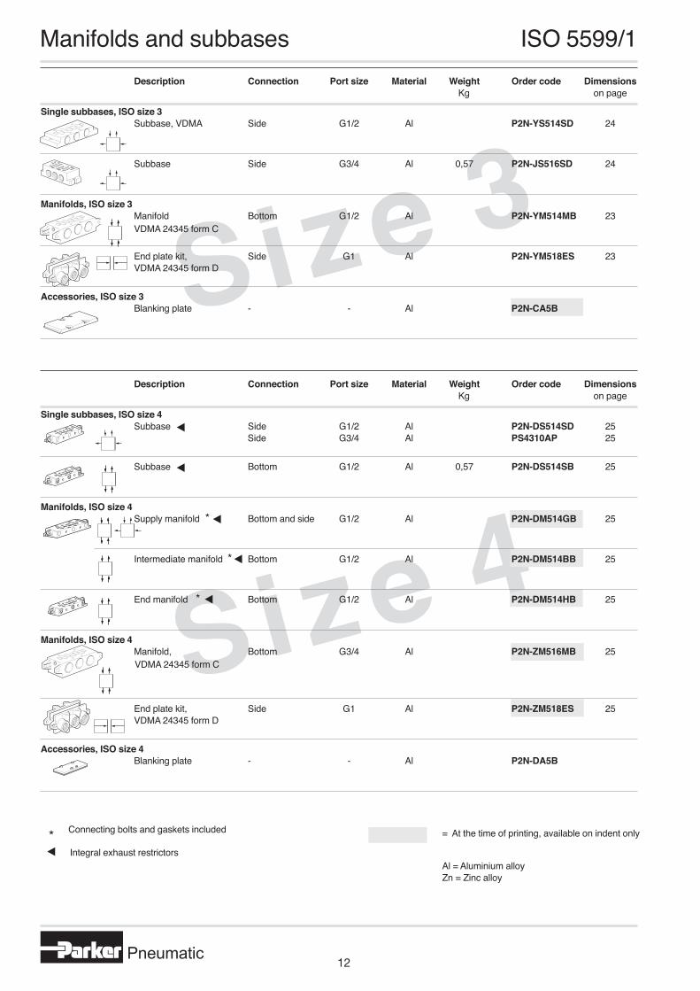
Description Connection Port size Material Weight Order code Dimensions Kg on page
Single subbases, ISO size 3 Subbase, VDMA Side G1/2 Al P2N-YS514SD 24 Subbase Side G3/4 Al 0,57 P2N-JS516SD 24
Manifolds, ISO size 3 Manifold Bottom G1/2 Al P2N-YM514MB 23
End plate kit, Side G1 Al P2N-YM518ES 23 VDMA 24345 form D
Accessories, ISO size 3 Blanking plate - - Al P2N-CA5B
Description Connection Port size Material Weight Order code Dimensions Kg on page
Single subbases, ISO size 4 Subbase Side G1/2 Al P2N-DS514SD 25 Side G3/4 Al PS4310AP 25 Subbase Bottom G1/2 Al 0,57 P2N-DS514SB 25
Manifolds, ISO size 4 Supply manifold * Bottom and side G1/2 Al P2N-DM514GB 25
Intermediate manifold * Bottom G1/2 Al P2N-DM514BB 25
End manifold * Bottom G1/2 Al P2N-DM514HB 25
Manifolds, ISO size 4 Manifold, Bottom G3/4 Al P2N-ZM516MB 25
End plate kit, Side G1 Al P2N-ZM518ES 25 VDMA 24345 form D
Accessories, ISO size 4 Blanking plate - - Al P2N-DA5B
Manifolds and subbases ISO 5599/1
Connecting bolts and gaskets included
VDMA 24345 form C
= At the time of printing, available on indent only
VDMA 24345 form C
Integral exhaust restrictors*
Al = Aluminium alloyZn = Zinc alloy
Pneumatic12
4 5
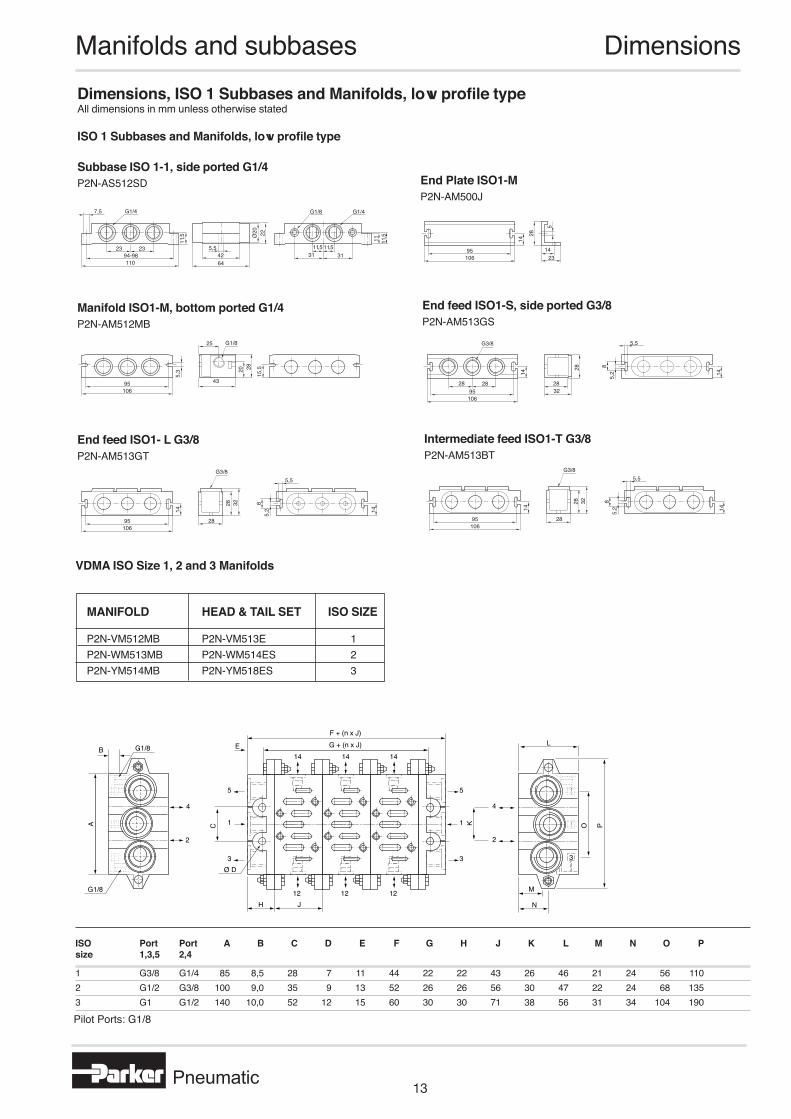
Manifolds and subbases DimensionsDimensions, ISO 1 Subbases and Manifolds, low profile typeAll dimensions in mm unless otherwise stated
ISO 1 Subbases and Manifolds, low profile type
Subbase ISO 1-1, side ported G1/4P2N-AS512SD
23 2394-98110
11,5
5,5
64
Ø20 22
11,5 11,531 31
11 11,5
G1/4 G1/4G1/8
42
7,5
Manifold ISO1-M, bottom ported G1/4P2N-AM512MB
End feed ISO1-S, side ported G3/8P2N-AM513GS
End feed ISO1- L G3/8P2N-AM513GT
Intermediate feed ISO1-T G3/8P2N-AM513BT
End Plate ISO1-MP2N-AM500J
95106
25 G1/8
20 28
43
5,3
15,5
95 32106
5,5G3/8
28
28
14 5,2 14
28 28
8
95
32
106
5,5G3/8
28
28
14 5,2 14
8
95
32
106
5,5G3/8
28
28
14 5,2 14
8
95106
14
14
23
28
5
K
2
3
4
PO
M
N
L
H J12 12 12
G + (n x J)F + (n x J)
14 14 14
C
3
1
5
3
1
5
Ø D
A
B E
4
2
G1/8
G1/8
VDMA ISO Size 1, 2 and 3 Manifolds
ISO Port Port A B C D E F G H J K L M N O Psize 1,3,5 2,4
1 G3/8 G1/4 85 8,5 28 7 11 44 22 22 43 26 46 21 24 56 1102 G1/2 G3/8 100 9,0 35 9 13 52 26 26 56 30 47 22 24 68 1353 G1 G1/2 140 10,0 52 12 15 60 30 30 71 38 56 31 34 104 190
MANIFOLD HEAD & TAIL SET ISO SIZE
P2N-VM512MB P2N-VM513E 1P2N-WM513MB P2N-WM514ES 2P2N-YM514MB P2N-YM518ES 3
Pilot Ports: G1/8
Pneumatic13

6 7
Dimensions, Manifolds and subbasesAll dimensions in mm unless otherwise stated
Single subbase ISO 1, 2 and 3, side ported
Type ISO Port A B C D E F G H J K L M N P R size size
P2N-GS511SD 1 G1/8 100 40 29 50 45 30,5 11 18 10 22 10 5,4 14 9 18P2N-GS512SD 1 G1/4 100 40 29 50 45 30,5 11 18 10 22 10 5,4 14 9 18P2N-HS512SS 2 G1/4 116 50 32 58 52 34,0 13 19 10 26 10 6,4 19 12 24P2N-HS513SS 2 G3/8 116 50 32 58 52 34,0 13 19 10 26 10 6,4 19 12 24P2N-HS514SS 2 G1/2 124 51 42 62 56 37,0 18 24 10 34 10 6,4 19 12 24P2N-JS516SD 3 G3/4 149 71 60 74,5 68 45,0 21 33 10 40 18 6,6 24 16 32
Single subbase ISO 1 and 2 bottom ported
Type ISO Port A B C D E F G H J K L M N size size
P2N-GS512SB 1 G1/4 100 40 29 50 45 30,5 11 9,5 9,5 22 10 5,4 19P2N-HS513SB 2 G3/8 116 50 32 58 52 24,0 12 12,5 10 26 10 6,4 19
VDMA single subbase ISO1,2 and 3 , side ported
Type ISO Port A B C D E F G H I J K L M N O size size
P2N-VS512SD 1 G1/4 21,5 98 110 11 20 5,5 48 32 12 29 10 11 23 G1/4 G1/8P2N-WS513S 2 G3/8 28,0 112 124 14 26 6,6 56 40 15 37 13 14 30 G3/8 G1/8P2N-YS514SD 3 G1/2 34,0 136 149 17 17 6,6 71 32 16 45 18 17 22 G1/2 G1/8
Manifolds and subbases Dimensions
MB
E
ADE
N N
RP
PR
KK
3
1
5
LC
12
14
4
2 KK
GG
J
H
MB
E
ADE
N N
FG
GF
K
A
EK
FF
12
14
4
2
3
1
5
GG
ED
JH H
LC
Pilot Ports: G1/8
Pilot Ports: G1/8
A ABC
D E
ØFG
H
I IJ J
K L M
N NO
Pneumatic14
6
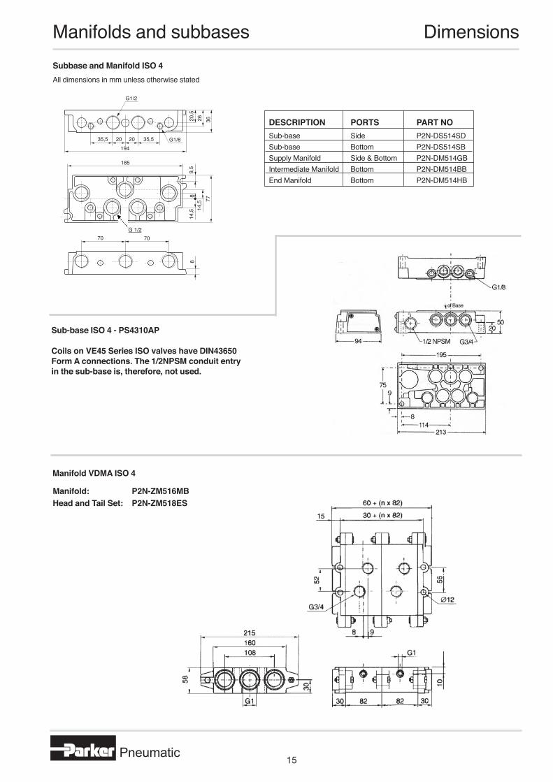
Manifolds and subbases DimensionsSubbase and Manifold ISO 4All dimensions in mm unless otherwise stated
Sub-base ISO 4 - PS4310AP
Manifold: P2N-ZM516MBHead and Tail Set: P2N-ZM518ES
DESCRIPTION PORTS PART NO Sub-base Side P2N-DS514SDSub-base Bottom P2N-DS514SBSupply Manifold Side & Bottom P2N-DM514GBIntermediate Manifold Bottom P2N-DM514BBEnd Manifold Bottom P2N-DM514HB
35,5 20 20 35,5194
185
20,5
26
G1/8
G1/2
814
,5 14,5
9,5
7736
8
70 70G 1/2
Manifold VDMA ISO 4
Coils on VE45 Series ISO valves have DIN43650 Form A connections. The 1/2NPSM conduit entry in the sub-base is, therefore, not used.
Pneumatic15
8
M B MB B
M2
M1
A
Ø R
K1G 1/8"
JK
PL
C
12
14
2
4
N
= =
G
FF
E D1D
H
13
5
Q
M2
M1
24 56 2046
35
13
Ø 8
43
129
11
28
Ø 6
110
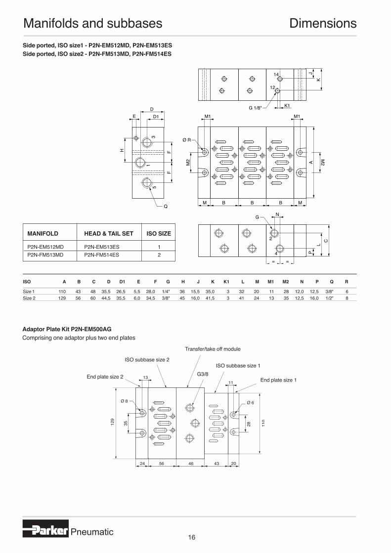
Side ported, ISO size1 - P2N-EM512MD, P2N-EM513ESSide ported, ISO size2 - P2N-FM513MD, P2N-FM514ES
ISO A B C D D1 E F G H J K K1 L M M1 M2 N P Q R
Size 1 110 43 48 35,5 26,5 5,5 28,0 1/4" 36 15,5 35,0 3 32 20 11 28 12,0 12,5 3/8" 6Size 2 129 56 60 44,5 35,5 6,0 34,5 3/8" 45 16,0 41,5 3 41 24 13 35 12,5 16,0 1/2" 8
ISO subbase size 2ISO subbase size 1
Transfer/take off module
Adaptor Plate Kit P2N-EM500AGComprising one adaptor plus two end plates
MANIFOLD HEAD & TAIL SET ISO SIZE
P2N-EM512MD P2N-EM513ES 1P2N-FM513MD P2N-FM514ES 2
Manifolds and subbases Dimensions
End plate size 1End plate size 2 G3/8
Pneumatic16