Embed Size (px)
Citation preview
Manual ENiso165C_C1_D00154_06_M_XXEN / 03/2021
ISOMETER® iso165C + iso165C-1Insulation Monitoring Device (IMD) for unearthed
DC drive systems (IT systems) in electric vehicles

2 iso165C_C1_D00154_06_M_XXEN / 03/2021
Service and support for Bender products
First-level support Technical support Carl-Benz-Strasse 8 • 35305 Grünberg • Germany Telephone: +49 6401 807-760 0700BenderHelp * Fax: +49 6401 807-629 E-mail: [email protected] Available on 365 days from 7.00 a.m. to 8.00 p.m. (MEZ/UTC +1) * Landline German Telekom: Mon-Fri from 9.00 a.m. to 6 p.m.: 6.3 cents/30 sec.; remaining time: 6.3 cents/min. Mobile phone: higher, depending on mobile phone tariff
Repair service Repair, calibration and replacement service Londorfer Strasse 65 • 35305 Grünberg • Germany Telephone: +49 6401 807-780 (technical issues) or +49 6401 807-784, -785 (commercial issues) Fax: +49 6401 807-789 E-mail: [email protected]
Field service On-site service Telephone: +49 6401 807-752, -762 (technical issues) or +49 6401 807-753 (commercial issues) Fax: +49 6401 807-759 E-mail: [email protected] Mon-Thu 7.00 a.m. to 4.00 p.m., Fri 7.00 a.m. to 1 p.m. (MEZ/UTC +1)

iso165C_C1_D00154_06_M_XXEN / 03/2021 3
ISOMETER® iso165C + iso165C-1
Inhaltsverzeichnis
1 General instructions .........................................................................71.1 How to use this manual ..............................................................................................71.2 Indication of important instructions and information ...................................71.2.1 Signs and symbols ........................................................................................................71.3 Training courses and seminars.................................................................................71.4 Delivery conditions .......................................................................................................71.5 Inspection, transport and storage ..........................................................................71.6 Warranty and liability...................................................................................................81.7 Disposal of Bender devices ........................................................................................81.8 Safety .................................................................................................................................8
2 Intended use .......................................................................................92.1 ISOMETER® iso165C and ISOMETER® iso165C-1 comparison .......................9
3 Function ............................................................................................ 103.1 Device features ........................................................................................................... 103.2 Product description ................................................................................................... 103.3 Functional description ............................................................................................. 113.4 Self test ........................................................................................................................... 12
4 Dimensions ....................................................................................... 134.1 Device dimensions..................................................................................................... 134.2 Enclosure and mounting ......................................................................................... 14
5 Connection ....................................................................................... 155.1 Connection conditions ............................................................................................. 155.2 Connectivity ................................................................................................................. 155.2.1 Connector pin assignment ..................................................................................... 165.2.2 Wiring diagram 100 Ω/2.2 kΩ resistance at HST_1/HST_2 ......................... 175.3 Typical application ..................................................................................................... 175.4 Special application notes ........................................................................................ 17
6 Operation .......................................................................................... 186.1 Messages ....................................................................................................................... 186.2 IMD_Info ........................................................................................................................ 186.3 IMD_Request ................................................................................................................ 196.3.1 Example ......................................................................................................................... 206.4 IMD_Response ............................................................................................................. 21
4 iso165C_C1_D00154_06_M_XXEN / 03/2021
7 Command and data value descriptions...................................... 227.1 Naming convention .................................................................................................. 227.1.1 Signal naming .............................................................................................................. 227.1.2 DBC signal naming .................................................................................................... 227.2 Command descriptions ............................................................................................ 227.2.1 Control (CTL) commands ........................................................................................ 23
7.2.1.1 S_IMC_CTL_SELFTEST ..........................................................................................................237.2.1.2 S_VIFC_CTL_IMC_RESET .....................................................................................................237.2.1.3 S_VIFC_CTL_LOCK .................................................................................................................237.2.1.4 S_VIFC_CTL_MEASUREMENT ............................................................................................23
7.2.2 SET commands ............................................................................................................ 247.2.2.1 S_IMC_SET_R_ISO_ERR_THR .............................................................................................247.2.2.2 S_IMC_SET_R_ISO_WRN_THR ...........................................................................................247.2.2.3 S_IMC_SET_MEAN_FACTOR ..............................................................................................247.2.2.4 S_VIFC_SET_HV_RELAIS ......................................................................................................24
7.2.3 GET commands ........................................................................................................... 257.2.3.1 S_VIFC_DUMMY .....................................................................................................................257.2.3.2 S_IMC_GET_STATUS .............................................................................................................257.2.3.3 S_IMC_GET_R_ISO .................................................................................................................257.2.3.4 S_IMC_GET_R_ISO_ERR_THR ............................................................................................257.2.3.5 S_IMC_GET_R_ISO_WRN_THR ..........................................................................................267.2.3.6 S_IMC_GET_MEAN_FACTOR .............................................................................................267.2.3.7 S_IMC_GET_HV_1 ..................................................................................................................267.2.3.8 S_IMC_GET_HV_2 ..................................................................................................................267.2.3.9 S_IMC_GET_VERSION ...........................................................................................................277.2.3.10 S_IMC_GET_TEST_CNT ........................................................................................................277.2.3.11 S_IMC_GET_MANUFACTURER ..........................................................................................277.2.3.12 S_VIFC_GET_STATUS ............................................................................................................277.2.3.13 S_VIFC_GET_HV_RELAIS .....................................................................................................287.2.3.14 S_VIFC_GET_IMC_ALIVE ......................................................................................................287.2.3.15 S_VIFC_GET_VERSION ..........................................................................................................287.2.3.16 S_VIFC_GET_LOCK ................................................................................................................28
7.3 Data value descriptions ........................................................................................... 297.3.1 D_IMC_SELFTEST_SCR .............................................................................................. 297.3.2 D_IMC_R_ISO_ERR_THR .......................................................................................... 297.3.3 D_IMC_R_ISO_WRN_THR ........................................................................................ 297.3.4 D_IMC_MEAN_FACTOR ........................................................................................... 297.3.5 D_IMC_STATUS ........................................................................................................... 307.3.6 D_IMC_STATUS_EXT ................................................................................................. 317.3.7 D_IMC_R_ISO ............................................................................................................... 327.3.8 D_IMC_R_ISO_BIAS ................................................................................................... 327.3.9 D_IMC_R_ISO_CNT .................................................................................................... 32

iso165C_C1_D00154_06_M_XXEN / 03/2021 5
ISOMETER® iso165C + iso165C-1
7.3.10 D_IMC_MANUFACT_INDEX .................................................................................... 327.3.11 D_IMC_MANUFACT_DATA ..................................................................................... 337.3.12 D_IMC_HV_1 ................................................................................................................ 337.3.13 D_IMC_HV_2 ................................................................................................................ 337.3.14 D_IMC_VERSION_INDEX .......................................................................................... 337.3.15 D_IMC_VERSION ......................................................................................................... 347.3.16 D_IMC_TEST_CNT ...................................................................................................... 347.3.17 D_VIFC_HV_RELAIS.................................................................................................... 347.3.18 D_VIFC_MEASURE_MODE ....................................................................................... 347.3.19 D_VIFC_LOCK_MODE ............................................................................................... 357.3.20 D_VIFC_LOCK_PWD .................................................................................................. 357.3.21 D_VIFC_HV_RELAIS_STATE ..................................................................................... 357.3.22 D_VIFC_VERSION_INDEX ......................................................................................... 357.3.23 D_VIFC_VERSION ........................................................................................................ 357.3.24 D_VIFC_IMC_ALIVE .................................................................................................... 367.3.25 D_VIFC_STATUS .......................................................................................................... 377.3.26 D_IMD_ERROR_CODE ............................................................................................... 387.3.27 D_IMD_FAILED_CMD ................................................................................................ 38
8 Data .................................................................................................... 398.1 Technical data ............................................................................................................. 398.2 Ordering data .............................................................................................................. 418.2.1 Accessories ................................................................................................................... 418.3 Standards - corresponding norms and regulations ...................................... 428.3.1 General ........................................................................................................................... 428.3.2 EMC.................................................................................................................................. 428.3.3 Environmental ............................................................................................................. 42
6 iso165C_C1_D00154_06_M_XXEN / 03/2021

iso165C_C1_D00154_06_M_XXEN / 03/2021 7
ISOMETER® iso165C + iso165C-1
1 General instructions
1.1 How to use this manual This manual is intended for qualified personnel working in electrical engineering and elec tronics! Part of the device documentation, in addition to this manual, is the enclosed “Safety instructions for Bender products”.
Read the manual before installing, connecting and commissioning the device. Always keep the manual within easy reach for future reference.
1.2 Indication of important instructions and information
I Danger! Indicates a high risk of danger that will result in death or serious injury if not avoided.
I Warning! Indicates a medium risk of danger that can lead to death or serious injury, if not avoi-ded.
I Caution! Indicates a low-level risk that can result in minor or moderate injury or damage to pro-perty if not avoided.
i Information can help to optimise the use of the product.
1.2.1 Signs and symbols
Disposal Temperature range protect from dust
protect from wet-ness
Recycling RoHS guidelines
1.3 Training courses and seminarswww.bender.de > Know-how-> Seminars.
1.4 Delivery conditionsThe conditions of sale and delivery set out by Bender apply. These can be obtained from Bender in printed or electronic format.
The following applies to software products:
“Software clause in respect of the licensing of standard software as part of deliveries, modifications and changes to general delivery conditions for products and services in the electrical industry.”
1.5 Inspection, transport and storageCheck the shipping and device packaging for transport damage and scope of delivery. The following must be ob-served when storing the devices:
Die Elektroindustrie
8 iso165C_C1_D00154_06_M_XXEN / 03/2021
General instructions
1.6 Warranty and liabilityWarranty and liability claims in the event of injury to persons or damage to property are excluded in case of:
• Improper use of the device.• Incorrect mounting, commissioning, operation and maintenance of the device.• Failure to observe the instructions in this operating manual regarding transport, commission-
ing, operation and maintenance of the device.• Unauthorised changes to the device made by parties other than the manufacturer.• Non-observance of technical data. • Repairs carried out incorrectly.• Use of accessories and spare parts not recommended by Bender.• Catastrophes caused by external influences and force majeure.• Mounting and installation with device combinations not recommended by the manufacturer.
This operating manual and the enclosed safety instructions must be observed by all persons working with the device. Furthermore, the rules and regulations that apply for accident prevention at the place of use must be observed.
1.7 Disposal of Bender devicesAbide by the national regulations and laws governing the disposal of this device.
For more information on the disposal of Bender devices, refer to
www.bender.de -> Service & support.
1.8 SafetyIf the device is used outside the Federal Republic of Germany, the applicable local standards and regu-lations must be complied with. In Europe, the European standard EN 50110 applies.
I Danger! Risk of electrocution due to electric shock! Touching live parts of the system carries the risk of:
• A fatal electric shock• Damage to the electrical installation• Destruction of the device
Before installing and connecting the device, make sure that the installation has been de-energised. The rules for working on electrical systems must be observed.
iso165C_C1_D00154_06_M_XXEN / 03/2021 9
ISOMETER® iso165C + iso165C-1
2 Intended useThe ISOMETER® iso165C and ISOMETER® iso165C-1 monitor the high-voltage (HV) insulation resistance between the car chassis and the active HV components of an unearthed DC drive system (IT system) in electric vehicles with supply voltages of DC 0 V...600 V. The insulation condition is monitored on the DC side as well as on the AC motor side of the electrical drive system. Existing insulation faults will be reliably signaled even under high system interferences, which can be caused by motor control processes, acceleration or energy recovery for example.
Both ISOMETER®s feature a CAN bus interface and can be easily integrated into an existing CAN envi-ronment in hybrid or fully electric vehicles.
i Only one active insulation monitoring device (IMD) in a galvanically interconnected system is per-mitted. If IT systems are to be interconnected via a coupling switch, it must be ensured via a supervi-sory unit that all other IMDs are separated from the IT system and switched to inactive. IT systems coupled via capacitors or diodes can also influence the insulation monitoring system. For this rea-son, central control of the various IMDs must be implemented.
Any other use than that described in this manual is regarded as improper.
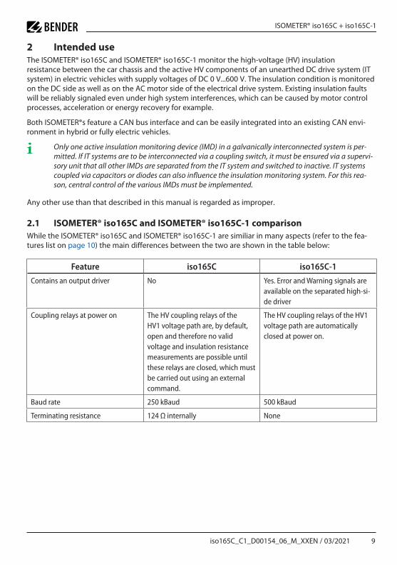
2.1 ISOMETER® iso165C and ISOMETER® iso165C-1 comparisonWhile the ISOMETER® iso165C and ISOMETER® iso165C-1 are similiar in many aspects (refer to the fea-tures list on page 10) the main differences between the two are shown in the table below:
Feature iso165C iso165C-1
Contains an output driver No Yes. Error and Warning signals are available on the separated high-si-de driver
Coupling relays at power on The HV coupling relays of the HV1 voltage path are, by default, open and therefore no valid voltage and insulation resistance measurements are possible until these relays are closed, which must be carried out using an external command.
The HV coupling relays of the HV1 voltage path are automatically closed at power on.
Baud rate 250 kBaud 500 kBaud
Terminating resistance 124 Ω internally None

10 iso165C_C1_D00154_06_M_XXEN / 03/2021
Function
3 Function
3.1 Device features• Insulation monitoring of AC and DC insulation faults for unearthed systems (IT systems) from
0 V…600 V peak• Power supply for all internal voltages• Continuous measurement of insulation resistance from 0 Ω…50 MΩ• Response time of ≤ 20 s for measured insulation resistance (using Direct Current Pulse (DCP)• Automatic adaptation to the existing system leakage capacitance (≤ 1 μF)• Detection of ground faults and lost ground line• Measurement of a second voltage• The device works when:
– HV is unstable – HV is powered off – There are symmetric or asymmetric insulation faults – Faults exist between HV lines and the supply voltage
• Galvanic insulation of all signals from the HV side• HV coupled network• CAN bus interface• Light weight: < 220 g (including housing and connection frame)• iso165C-1 only: The iso165C-1 variant features Error and Warning signals on the• separated high-side driver
3.2 Product descriptionThe ISOMETER® monitors the insulation resistance between the active HV components of an electrical drive system (U
n = DC 0 V…600 V) and the reference earth (chassis ground). The patented measure-
ment technology is used to monitor the condition of the insulation on the DC side as well as on the AC motor side of the electrical drive system.
The ISOMETER® is assembled with three connectors. To achieve internal galvanic separation, connector 1 is connected to low-voltage (LV) areas and connectors 2 and 3 are connected to the HV areas in the car environment.
The device meets the increased automotive requirements with regard to environmental conditions (e.g. temperatures and vibration, EMC). The ISOMETER® CAN bus interface allows it to integrate seamlessly into an existing CAN environment.
iso165C_C1_D00154_06_M_XXEN / 03/2021 11
ISOMETER® iso165C + iso165C-1
IMC
HV 2
HV 1
Power supply
VIFCSBC
+12 V -12 V+5 V
HV relays
HV Access
VCC_2
Reset
Alive
Tx
Rx
Pulse generator
Filter stage 2
Filter stage 1
+ 40 Vmeasurementpower supply
Reset
INH
T_30
VCC_1
CANPhy
HS_CAN_H
HS_CAN_L
GND_ISO
GNDD
C
T_31_KE C
T_31_EGNDD
HV_2_POS
HV_2_NEG
HV_1_POS
HV_1_NEG
iso165
Galvanic isolation
Error
Warning
ISOMETER iso165C-1only
R
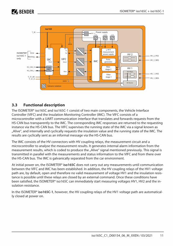
3.3 Functional descriptionThe ISOMETER® iso165C and iso165C-1 consist of two main components, the Vehicle Interface Controller (VIFC) and the Insulation Monitoring Controller (IMC). The VIFC consists of a microcontroller with a UART communication interface that translates and forwards requests from the HS-CAN bus transparently to the IMC. The corresponding IMC responses are returned to the requesting instance via the HS-CAN bus. The VIFC supervises the running state of the IMC via a signal known as „Alive“, and internally and cyclically requests the insulation value and the running state of the IMC. The results are cyclically sent as an informal message via the HS-CAN bus.
The IMC consists of the HV connectors with HV coupling relays, the measurement circuit and a microcontroller to analyse the measurement results. It generates internal alarm information from the measurement results, which is coded to produce the „Alive“ signal mentioned previously. This signal is transmitted in parallel with the measurements and status information to the VIFC and from there over the HS-CAN bus. The IMC is galvanically separated from the car environment.
At initial power on, the ISOMETER® iso165C does not carry out any measurements until communication between the VIFC and IMC has been established. In addition, the HV coupling relays of the HV1 voltage path are, by default, open and therefore no valid measurement of voltage HV1 and the insulation resis-tance is possible until these relays are closed by an external command. Once these conditions have been satisfied, the ISOMETER® iso165C can immediately start measuring voltages HV1, HV2 and the in-sulation resistance.
In the ISOMETER® iso165C-1, however, the HV coupling relays of the HV1 voltage path are automatical-ly closed at power on.
12 iso165C_C1_D00154_06_M_XXEN / 03/2021
Function
The initial measurement values after power up are:
HV relays open HV relays closed
Insulation resistance 50,000 kΩ Value in kΩ
Voltage of HV1 0 V Value in V
Voltage of HV2 Value in V Value in V
The ISOMETER® generates a pulsed measuring voltage that is superimposed on the IT system by termi-nals T_31_E/KE (chassis). Because the connection between the terminals E/KE and the chassis ground (T_31) is continuously monitored, it is necessary to install two separated conductors from terminals T_31_E/KE to chassis ground.
3.4 Self testTo optimize the start-up time, the ISOMETER® does not automatically execute a self test during boot up. Instead the execution of a self test is the responsibility of the external supervising system and has to be triggered via the CAN interface. A self test must be requested and can only be carried out when the coupling relays are open. The self test can be long (approximately 10 s) or short (approximately 1-2 s), and during this time the ISOMETER® is not able to perform insulation monitoring.

iso165C_C1_D00154_06_M_XXEN / 03/2021 13
ISOMETER® iso165C + iso165C-1
4 Dimensions
4.1 Device dimensions
All dimensions in mm
111.
4 ±
2
96 ±
0.6
(92.
01)
(97.
85)
141.82 ±2
43.2 ±182 ±0.6
ø 6 (4x)
A
A
DMC4
0.54x
Max. permissible unevenness between the mounting points
14 iso165C_C1_D00154_06_M_XXEN / 03/2021
Dimensions
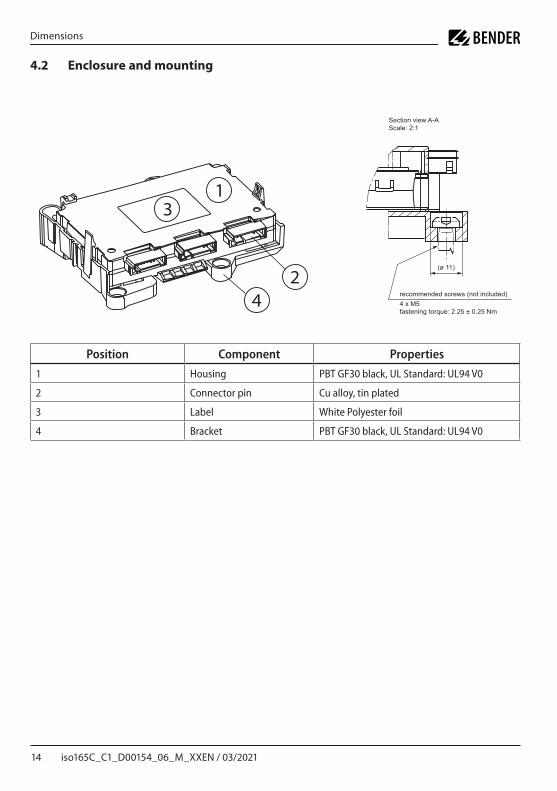
4.2 Enclosure and mounting
Position Component Properties
1 Housing PBT GF30 black, UL Standard: UL94 V0
2 Connector pin Cu alloy, tin plated
3 Label White Polyester foil
4 Bracket PBT GF30 black, UL Standard: UL94 V0
(ø 11)
31
42
Section view A-AScale: 2:1
recommended screws (not included)4 x M5fastening torque: 2.25 ± 0.25 Nm

iso165C_C1_D00154_06_M_XXEN / 03/2021 15
ISOMETER® iso165C + iso165C-1
5 Connection
5.1 Connection conditions
I Danger! Risk of electric shock! The terminals HV1 ± / HV2 ± may have nominal voltages measuring up to 600 V. Touching live parts of the system carries the risk of electric shock. Therefore, the device is only to be operated with mounted and locked terminal covers.
I Caution! Check proper connection of the device! In order to check that the device is properly con-nected, a function test must be carried out before system commissioning by measuring a ground fault using a suitable resistance.
I Caution! Connect terminals T_31_E and T_31_KE separately to the chassis! Terminals T_31_E and T_31_KE must be connected separately to the chassis.
I Caution! Risk of injury from sharp-edged terminals! Handle housing and terminals with care.
I Caution! Ensure disconnection from the IT system! In every conductively connected system only one IMD may be connected. When performing insulation and dielectric tests on the system, the IMD must be disconnected by opening the HV relays for the duration of the test.
i When a monitored AC system contains galvanically coupled DC circuits, the following applies: An in-sulation fault can only be accurately detected if a minimum current of > 10 mA flows through the rectifier valves.
5.2 Connectivity
Connector*) Type Code Colour
1 1719183-1 A Black
2 1719183-2 B White
3 1719183-3 C Blue
*) Please refer to „Data“ on page 39 for detailed connector information.
1 2 3

16 iso165C_C1_D00154_06_M_XXEN / 03/2021
Connection
5.2.1 Connector pin assignment
Connector/function Pin no. Signal
Connector 1 (LV) for:• Power supply• CAN interface• High-side driver• Chassis loop
1 T_31_KE_2 (vehicle internal earthing structure)
2 Reserved
3 HST_2 (High-side driver 2, iso Error) - iso165C-1 only
4 HST_1 (High-side driver 1, iso Warning) - iso165C-1 only
5 HS-CAN_L
6 HS-CAN_H
7 T_31_E_2 (vehicle internal earthing structure)
8 T_30 - 12V switched supply(5A fuse, Ignition and Charging FET)
Connector 2 (HV1) for:• Insulation monitoring• Voltage measure-
ment HV1
1 HV1_POS
2 Reserved
3 Reserved
4 Reserved
5 Reserved
6 Reserved
7 Reserved
8 HV1_NEG
Connector 3 (HV2) for:• Voltage measure-
ment HV2
1 HV2_NEG
2 Reserved
3 Reserved
4 Reserved
5 Reserved
6 Reserved
7 Reserved
8 HV2_POS

iso165C_C1_D00154_06_M_XXEN / 03/2021 17
ISOMETER® iso165C + iso165C-1
5.2.2 Wiring diagram 100 Ω/2.2 kΩ resistance at HST_1/HST_2
5.3 Typical application
5.4 Special application notes• If terminals HV2 are connected in parallel to terminals HV1 (i.e. a galvanically connected HV
system), the measured insulation resistance will be monitored including a +10 % offset to the real insulation value.
• The HV2 terminals could be used for voltage monitoring at disconnected HV sections (e.g. voltage monitoring of a charging plug).
100 Ω
2,2 kΩ
Kl. 31
HST_1/HST_2
RF3
RF2
RISO AC
G
RCon1
RF1
Ri
Rm
Um
R
CCon1
RCon2CCon2
RCon3CCon3
RInv1RISO DC
CInv1
RInv2CInv2
RInv3CInv3Inverter
RESS 2RESS 1
RBAT4CBAT4
RBAT3CBAT3
RBAT1CBAT1
RDC2CDC2
RAC2CAC2
RAC1CAC1
RDC1CDC1
RBAT2CBAT2
EV Inlet
Electrical Chassis / Protective equipotential bonding
IMD
PFC
M

18 iso165C_C1_D00154_06_M_XXEN / 03/2021
Operation
6 Operation
6.1 MessagesCommunication between a requesting instance in the vehicle environment and the ISOMETER® takes place over the HS-CAN bus. The ISOMETER® can handle the following HS-CAN messages:
Message CAN ID Direction Cyclic
IMD_Info 0x37 Tx 1 s
IMD_Request 0x22 Rx -
IMD_Response 0x23 Tx -
The messages contain either DataByte or DataWord values. The byte order for the Data-Word values is:
Byte orderDataByte
7............0
Byte order DataWord
LowByte HighByte
7............0 15...........8
6.2 IMD_InfoIMD_Info is cyclically sent once per second from the ISOMETER® and contains data values that represent the insulation resistance and the internal operating states of the VIFC and IMC.
Byte no. 0 1 2 3 4 5 6 7
D_IMC_R _ISO D_IMC_STATUS D_VIFC_STATUS Unused Unused
Data value descriptions can be found in chapter 7.3 on page 29
The following example contains IMC status information:
CAN ID (Info) DLC* Data1 Data2 Data3 Data4 Data5 Data6
0x37 0x6 dc dc IMC_STATUS_LSB
IMC_STA-TUS_MSB
dc dc
*DLC = Data Length Code

iso165C_C1_D00154_06_M_XXEN / 03/2021 19
ISOMETER® iso165C + iso165C-1
6.3 IMD_RequestIMD_Request is a request to the ISOMETER® and will always generate an answer message IMD_Response. It can handle Control (CTL), SET and GET commands.
A request has the following format:
Byte 0 1 2 3 4 5 6 7
CMD Data1 Data2 Data3 Data4 Unused Unused Unused
DataWord1 DataWord2
Definitions of DataWord1 and DataWord2 for different commands can be found in „Command descriptions“ on page 22.
For synchronous processing of the asynchronously received IMD_Request commands, the VIFC imple-ments a queue which operates on the First In, First Out (FIFO) principle. If the queue is full, an error res-ponse is generated and the request is dropped by the ISOMETER®. The “Queue full“ error response is not generated for every single request and may be generated only after a certain number of requests have been made.
To avoid processing commands that could mistakenly modify the system configuration during standard operation, the ISOMETER® has implemented a locking mechanism. The locking state can be changed with the command S_VIFC_CTL_LOCK.
Control (CTL) commands
CMD DBC command description Locked
0x21 S_IMC_CTL_SELFTEST
0xC8 S_VIFC_CTL_IMC_RESET
0xCA S_VIFC_CTL_LOCK
0xCB S_VIFC_CTL_MEASUREMENT
SET commands
CMD DBC command description Locked
0x28 S_IMC_SET_R_ISO_ERR_THR X
0x29 S_IMC_SET_R_ISO_WRN_THR X
0x2B S_IMC_SET_MEAN_FACTOR X
0xD2 S_VIFC_SET_HV_RELAIS
20 iso165C_C1_D00154_06_M_XXEN / 03/2021
Operation
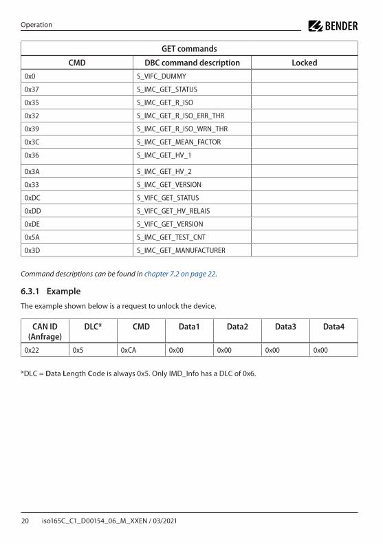
GET commands
CMD DBC command description Locked
0x0 S_VIFC_DUMMY
0x37 S_IMC_GET_STATUS
0x35 S_IMC_GET_R_ISO
0x32 S_IMC_GET_R_ISO_ERR_THR
0x39 S_IMC_GET_R_ISO_WRN_THR
0x3C S_IMC_GET_MEAN_FACTOR
0x36 S_IMC_GET_HV_1
0x3A S_IMC_GET_HV_2
0x33 S_IMC_GET_VERSION
0xDC S_VIFC_GET_STATUS
0xDD S_VIFC_GET_HV_RELAIS
0xDE S_VIFC_GET_VERSION
0x5A S_IMC_GET_TEST_CNT
0x3D S_IMC_GET_MANUFACTURER
Command descriptions can be found in chapter 7.2 on page 22.
6.3.1 Example
The example shown below is a request to unlock the device.
CAN ID(Anfrage)
DLC* CMD Data1 Data2 Data3 Data4
0x22 0x5 0xCA 0x00 0x00 0x00 0x00
*DLC = Data Length Code is always 0x5. Only IMD_Info has a DLC of 0x6.

iso165C_C1_D00154_06_M_XXEN / 03/2021 21
ISOMETER® iso165C + iso165C-1
6.4 IMD_ResponseIMD_Response is generated exclusively as an answer to the IMD_Request command. The system gua-rantees that every request is answered with a response if the IMD_Request is accepted by the queue implementation. The response can have one of two frame formats: a valid response is returned in the event the request can be successfully answered. Otherwise an error response is returned, the format of which contains an error code that specifies the reason.
Valid response format:
Byte 0 1 2 3 4
CMD Data1 Data2 Data3 Data4
DataWord1 DataWord2
Error response format:
Byte 0 1 2 3 4
0xFF D_IMD_ERROR_CODE D_IMD_FAILED_CMD 0x00

22 iso165C_C1_D00154_06_M_XXEN / 03/2021
Command and data value descriptions
7 Command and data value descriptions
7.1 Naming convention
7.1.1 Signal naming
Prefix Description
S_ Command
D_ Data value
P_ Physical interface
7.1.2 DBC signal naming
The data value identifier „D_“ is not included in DBC signal naming due to redundancy. Instead an identifier is added that allows the same data value identifier to be used in different messages and which avoids any naming conflict in the DBC. The DBC identifier identifies the sender of the message (Master or IMD) and the command type, i.e. Control (CTL), SET or GET. Replace the DBC identifier with the data value identifier „D_“ to obtain all valid data values for this DBC sig-nal.
Prefix Description
MC_ Master Control request data value
MS_ Master Set request data value
MG_ Master Get request data value
IC_ IMD Control response data value
IS_ IMD Set response data value
IG_ IMD Get response data value
II_ IMD Info data value
7.2 Command descriptionsThe message parameters are coded in bytes 2 to 5 and provide the possibility to enhance the request or response with additional information. If no additional message parameters are listed in this chapter the parameter should be initialized with ‚0‘. Parameters in response commands not described here have no concrete meaning in the system.
iso165C_C1_D00154_06_M_XXEN / 03/2021 23
ISOMETER® iso165C + iso165C-1
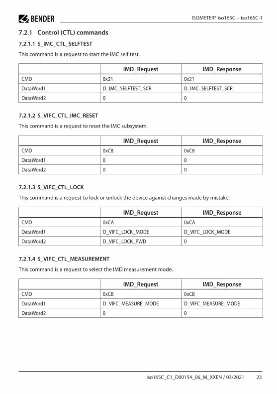
7.2.1 Control (CTL) commands
7.2.1.1 S_IMC_CTL_SELFTEST
This command is a request to start the IMC self test.
IMD_Request IMD_Response
CMD 0x21 0x21
DataWord1 D_IMC_SELFTEST_SCR D_IMC_SELFTEST_SCR
DataWord2 0 0
7.2.1.2 S_VIFC_CTL_IMC_RESET
This command is a request to reset the IMC subsystem.
IMD_Request IMD_Response
CMD 0xC8 0xC8
DataWord1 0 0
DataWord2 0 0
7.2.1.3 S_VIFC_CTL_LOCK
This command is a request to lock or unlock the device against changes made by mistake.
IMD_Request IMD_Response
CMD 0xCA 0xCA
DataWord1 D_VIFC_LOCK_MODE D_VIFC_LOCK_MODE
DataWord2 D_VIFC_LOCK_PWD 0
7.2.1.4 S_VIFC_CTL_MEASUREMENT
This command is a request to select the IMD measurement mode.
IMD_Request IMD_Response
CMD 0xCB 0xCB
DataWord1 D_VIFC_MEASURE_MODE D_VIFC_MEASURE_MODE
DataWord2 0 0

24 iso165C_C1_D00154_06_M_XXEN / 03/2021
Command and data value descriptions
7.2.2 SET commands
7.2.2.1 S_IMC_SET_R_ISO_ERR_THR
This command is a request to set the insulation fault (error) threshold.
IMD_Request IMD_Response
CMD 0x28 0x28
DataWord1 D_IMC_R_ISO_ERR_THR D_IMC_R_ISO_ERR_THR
DataWord2 0 0
7.2.2.2 S_IMC_SET_R_ISO_WRN_THR
This command is a request to set the insulation warning threshold.
IMD_Request IMD_Response
CMD 0x29 0x29
DataWord1 D_IMC_R_ISO_WRN_THR D_IMC_R_ISO_WRN_THR
DataWord2 0 0
7.2.2.3 S_IMC_SET_MEAN_FACTOR
This command is a request to set the mean factor of the insulation resistance averaging algorithm.
IMD_Request IMD_Response
CMD 0x2B 0x2B
DataWord1 D_IMC_MEAN_FACTOR D_IMC_MEAN_FACTOR
DataWord2 0 0
7.2.2.4 S_VIFC_SET_HV_RELAIS
This command is a request to change the state of the HV relays in the HV coupling network.
IMD_Request IMD_Response
CMD 0xD2 0xD2
DataWord1 D_VIFC_HV_RELAIS D_VIFC_HV_RELAIS
DataWord2 D_VIFC_HV_RELAIS_STATE D_VIFC_HV_RELAIS_STATE
iso165C_C1_D00154_06_M_XXEN / 03/2021 25
ISOMETER® iso165C + iso165C-1
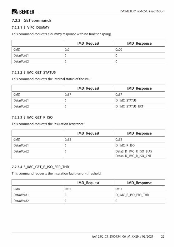
7.2.3 GET commands
7.2.3.1 S_VIFC_DUMMY
This command requests a dummy response with no function (ping).
IMD_Request IMD_Response
CMD 0x0 0x00
DataWord1 0 0
DataWord2 0 0
7.2.3.2 S_IMC_GET_STATUS
This command requests the internal status of the IMC.
IMD_Request IMD_Response
CMD 0x37 0x37
DataWord1 0 D_IMC_STATUS
DataWord2 0 D_IMC_STATUS_EXT
7.2.3.3 S_IMC_GET_R_ISO
This command requests the insulation resistance.
IMD_Request IMD_Response
CMD 0x35 0x35
DataWord1 0 D_IMC_R_ISO
DataWord2 0 Data3: D_IMC_R_ISO_BIASData4: D_IMC_R_ISO_CNT
7.2.3.4 S_IMC_GET_R_ISO_ERR_THR
This command requests the insulation fault (error) threshold.
IMD_Request IMD_Response
CMD 0x32 0x32
DataWord1 0 D_IMC_R_ISO_ERR_THR
DataWord2 0 0

26 iso165C_C1_D00154_06_M_XXEN / 03/2021
Command and data value descriptions
7.2.3.5 S_IMC_GET_R_ISO_WRN_THR
This command requests the insulation warning threshold.
IMD_Request IMD_Response
CMD 0x39 0x39
DataWord1 0 D_IMC_R_ISO_WRN_THR
DataWord2 0 0
7.2.3.6 S_IMC_GET_MEAN_FACTOR
This command requests the mean factor of the insulation resistance mean algorithm.
IMD_Request IMD_Response
CMD 0x3C 0x3C
DataWord1 0 D_IMC_MEAN_FACTOR
DataWord2 0 0
7.2.3.7 S_IMC_GET_HV_1
This command requests the HV value between HV1_POS and HV1_NEG.
IMD_Request IMD_Response
CMD 0x36 0x36
DataWord1 0 D_IMC_HV_1
DataWord2 0 0
7.2.3.8 S_IMC_GET_HV_2
This command requests the HV value between HV2_POS and HV2_NEG.
IMD_Request IMD_Response
CMD 0x3A 0x3A
DataWord1 0 D_IMC_HV_2
DataWord2 0 0

iso165C_C1_D00154_06_M_XXEN / 03/2021 27
ISOMETER® iso165C + iso165C-1
7.2.3.9 S_IMC_GET_VERSION
This command requests the software version of the IMC.
IMD_Request IMD_Response
CMD 0x33 0x33
DataWord1 D_IMC_VERSION_INDEX D_IMC_VERSION_INDEX
DataWord2 0 D_IMC_VERSION
7.2.3.10 S_IMC_GET_TEST_CNT
This command requests the insulation monitoring counter value.
IMD_Request IMD_Response
CMD 0x5A 0x5A
DataWord1 0 D_IMC_TEST_CNT
DataWord2 0 0
7.2.3.11 S_IMC_GET_MANUFACTURER
This command requests manufacturer information.
IMD_Request IMD_Response
CMD 0x3D 0x3D
DataWord1 D_IMC_MANUFACT_INDEX D_IMC_MANUFACT_INDEX
DataWord2 0 D_IMC_MANUFACT_DATA
7.2.3.12 S_VIFC_GET_STATUS
This command requests the internal status of the VIFC.
IMD_Request IMD_Response
CMD 0xDC 0xDC
DataWord1 0 D_VIFC_STATUS
DataWord2 0 0

28 iso165C_C1_D00154_06_M_XXEN / 03/2021
Command and data value descriptions
7.2.3.13 S_VIFC_GET_HV_RELAIS
This command requests the state of the HV relays in the HV coupling network.
IMD_Request IMD_Response
CMD 0xDD 0xDD
DataWord1 D_VIFC_HV_RELAIS D_VIFC_HV_RELAIS
DataWord2 0 D_VIFC_HV_RELAIS_STATE
7.2.3.14 S_VIFC_GET_IMC_ALIVE
This signal requests the „Alive“ state of the IMC.
IMD_Request IMD_Response
CMD 0xE2 0xE2
DataWord1 0 D_VIFC_IMC_ALIVE
DataWord2 0 0
7.2.3.15 S_VIFC_GET_VERSION
This command requests the software version of the VIFC.
IMD_Request IMD_Response
CMD 0xDE 0xDE
DataWord1 D_VIFC_VERSION_INDEX D_VIFC_VERSION_INDEX
DataWord2 0 D_VIFC_VERSION
7.2.3.16 S_VIFC_GET_LOCK
This signal requests the locking state of the ISOMETER® iso165C.
IMD_Request IMD_Response
CMD 0xE0 0xE0
DataWord1 0 D_VIFC_LOCK_MODE
DataWord2 0 0

iso165C_C1_D00154_06_M_XXEN / 03/2021 29
ISOMETER® iso165C + iso165C-1
7.3 Data value descriptions
7.3.1 D_IMC_SELFTEST_SCR
This data value represents the self-test scenario.
Value Description
0 No Action
1 OverAll scenario
2 ParameterConfig scenario
7.3.2 D_IMC_R_ISO_ERR_THR
This data value represents the threshold that causes an insulation error when the insulation resistance is lower than this value.
Unit kΩ
Default 55 (for iso165C)250 (for iso165C-1)
Resolution 1
Range 30…1,000
7.3.3 D_IMC_R_ISO_WRN_THR
This data value represents the threshold that causes an insulation warning when the insulation resistance is lower than this value.
Unit kΩ
Default 300 (for iso165C)400 (for iso165C-1)
Resolution 1
Range 40…2,000
7.3.4 D_IMC_MEAN_FACTOR
This data value represents the mean factor of the insulation resistance averaging algorithm.
Unit Number of measurements
Default 3
Resolution 1
Range 1…20

30 iso165C_C1_D00154_06_M_XXEN / 03/2021
Command and data value descriptions
7.3.5 D_IMC_STATUS
This data value represents the internal status of the IMC.
Bit Description Status
0 Insulation fault 0 = NoError1 = Error
1 Chassis fault 0 = NoError1 = Error
2 System failure 0 = NoError1 = Error
3 Calibration running 0 = NotRunning1 = Running
4 Self test running 0 = NotRunning1 = Running
5 Insulation warning 0 = NoWarning1 = Warning
6 Reserved
7 Reserved
8 Reserved
9 Reserved
10 Reserved
11 Reserved
12 Reserved
13 Reserved
14 Reserved
15 Reserved

iso165C_C1_D00154_06_M_XXEN / 03/2021 31
ISOMETER® iso165C + iso165C-1
7.3.6 D_IMC_STATUS_EXT
This data value represents device-internal IMC self-test results.
Bit Description Status
0 Calibration parameter 0 = NoError1 = Error
1 Hardware failure 0 = NoError1 = Error
2 EEPROM parameter 0 = NoError1 = Error
3 FLASH parameter 0 = NoError1 = Error
4 RAM parameter 0 = NoError1 = Error
5 Stack overflow 0 = NoError1 = Overflow
6 Reserved
7 Parameter value 0 = NoError1 = Error
8 Test pulse voltage/ARef 0 = NoError1 = Error
9 Voltage level (+12 V) 0 = NoError1 = Error
10 Voltage level (-12 V) 0 = NoError1 = Error
11 FuseBits valid/invalid 0 = NoError1 = Error
12 HV1 internal test voltage 0 = NoError1 = Error
13 HV2 internal test voltage 0 = NoError1 = Error
14 Manufacturer string valid/invalid 0 = NoError1 = Error
15 Reserved
32 iso165C_C1_D00154_06_M_XXEN / 03/2021
Command and data value descriptions
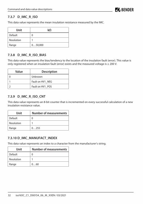
7.3.7 D_IMC_R_ISO
This data value represents the mean insulation resistance measured by the IMC.
Unit kΩ
Default 0
Resolution 1
Range 0…50,000
7.3.8 D_IMC_R_ISO_BIAS
This data value represents the bias/tendency to the location of the insulation fault (error). This value is only registered when an insulation fault (error) exists and the measured voltage is ≥ 200 V.
Value Description
0 Unknown
1 Fault on HV1_NEG
2 Fault on HV1_POS
7.3.9 D_IMC_R_ISO_CNT
This data value represents an 8-bit counter that is incremented on every successful calculation of a new insulation resistance value.
Unit Number of measurements
Default 0
Resolution 1
Range 0…255
7.3.10 D_IMC_MANUFACT_INDEX
This data value represents an index to a character from the manufacturer‘s string.
Unit Number of measurements
Default 0
Resolution 1
Range 0…60

iso165C_C1_D00154_06_M_XXEN / 03/2021 33
ISOMETER® iso165C + iso165C-1
7.3.11 D_IMC_MANUFACT_DATA
This data value represents the ASCII code of a character from the manufacturer‘s string.
Unit Number of measurements
Default 0
Resolution 1
Range 0…255
7.3.12 D_IMC_HV_1
This data value represents the HV between HV_1_POS and HV_1_NEG.
Unit V
Default 0
Resolution 1
Range 0…600
7.3.13 D_IMC_HV_2
This data value represents the HV between HV_2_POS and HV_2_NEG.
Unit V
Default 0
Resolution 1
Range 0…600
7.3.14 D_IMC_VERSION_INDEX
This data value represents the index to the software version of the IMC.
Value Description
0 IMC bootloader
1 IMC firmware
2 IMC firmware ID
3 IMC firmware Hash
34 iso165C_C1_D00154_06_M_XXEN / 03/2021
Command and data value descriptions
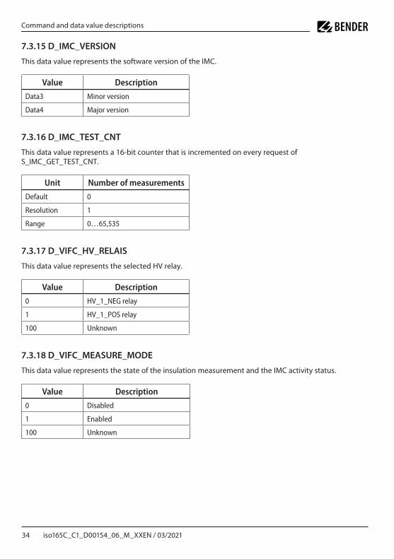
7.3.15 D_IMC_VERSION
This data value represents the software version of the IMC.
Value Description
Data3 Minor version
Data4 Major version
7.3.16 D_IMC_TEST_CNT
This data value represents a 16-bit counter that is incremented on every request of S_IMC_GET_TEST_CNT.
Unit Number of measurements
Default 0
Resolution 1
Range 0…65,535
7.3.17 D_VIFC_HV_RELAIS
This data value represents the selected HV relay.
Value Description
0 HV_1_NEG relay
1 HV_1_POS relay
100 Unknown
7.3.18 D_VIFC_MEASURE_MODE
This data value represents the state of the insulation measurement and the IMC activity status.
Value Description
0 Disabled
1 Enabled
100 Unknown
iso165C_C1_D00154_06_M_XXEN / 03/2021 35
ISOMETER® iso165C + iso165C-1
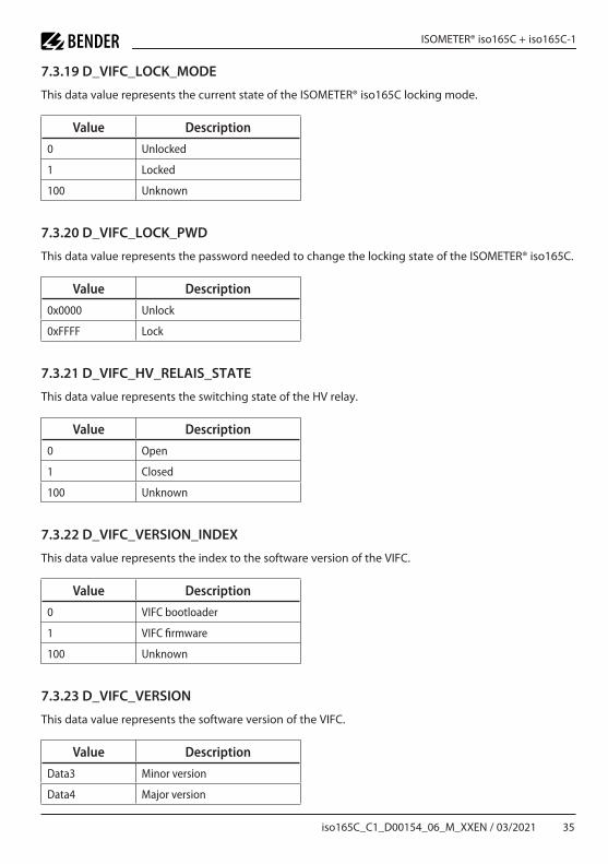
7.3.19 D_VIFC_LOCK_MODE
This data value represents the current state of the ISOMETER® iso165C locking mode.
Value Description
0 Unlocked
1 Locked
100 Unknown
7.3.20 D_VIFC_LOCK_PWD
This data value represents the password needed to change the locking state of the ISOMETER® iso165C.
Value Description
0x0000 Unlock
0xFFFF Lock
7.3.21 D_VIFC_HV_RELAIS_STATE
This data value represents the switching state of the HV relay.
Value Description
0 Open
1 Closed
100 Unknown
7.3.22 D_VIFC_VERSION_INDEX
This data value represents the index to the software version of the VIFC.
Value Description
0 VIFC bootloader
1 VIFC firmware
100 Unknown
7.3.23 D_VIFC_VERSION
This data value represents the software version of the VIFC.
Value Description
Data3 Minor version
Data4 Major version

36 iso165C_C1_D00154_06_M_XXEN / 03/2021
Command and data value descriptions
7.3.24 D_VIFC_IMC_ALIVE
This data value represents the „Alive“ state of the IMC.
Value Description
0 RunningThe IMC is up and running with no errors:• Initialization• Idle• Insulation warning• Self test• Calibration
1 ErrorThe IMC is up and running but has detected an error:• System failure• Insulation fault• Chassis fault
2 Performance errorThe VIFC has received the analogue „Alive“ signal but was not able to evaluate it correctly.
100 UnknownThe VIFC is not receiving the analogue „Alive“ signal from the IMC.
iso165C_C1_D00154_06_M_XXEN / 03/2021 37
ISOMETER® iso165C + iso165C-1
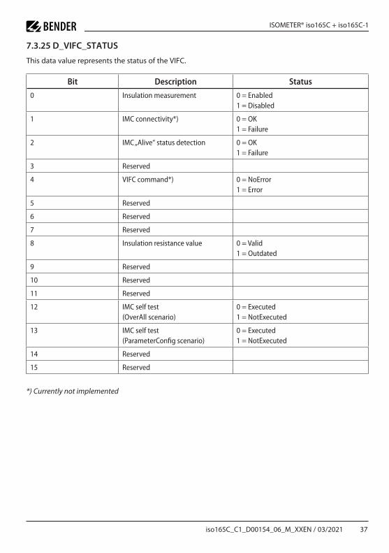
7.3.25 D_VIFC_STATUS
This data value represents the status of the VIFC.
Bit Description Status
0 Insulation measurement 0 = Enabled1 = Disabled
1 IMC connectivity*) 0 = OK1 = Failure
2 IMC „Alive“ status detection 0 = OK1 = Failure
3 Reserved
4 VIFC command*) 0 = NoError 1 = Error
5 Reserved
6 Reserved
7 Reserved
8 Insulation resistance value 0 = Valid1 = Outdated
9 Reserved
10 Reserved
11 Reserved
12 IMC self test(OverAll scenario)
0 = Executed1 = NotExecuted
13 IMC self test(ParameterConfig scenario)
0 = Executed1 = NotExecuted
14 Reserved
15 Reserved
*) Currently not implemented

38 iso165C_C1_D00154_06_M_XXEN / 03/2021
Command and data value descriptions
7.3.26 D_IMD_ERROR_CODE
This data value represents the IMC and VIFC error codes in the error frame.
IMC error codes
Value Description
32 Timeout 10 ms (incomplete frame)
33 Checksum error detected in frame
34 Invalid parameter
35 Unknown command
36 Error in EEPROM access
37 Repeated or missing frame
VIFC error codes
Value Description
1000 Command locked
1001 Queue full (Command rejected)
1002 Command unavailable (Measurement Off)
1032 Timeout 10 ms (incomplete frame)
1033 Checksum error detected in data frame
1034 Invalid parameter
1035 Unknown command
1037 Repeated or missing data frame
1038 No response (Timeout 60 ms)
1039 Communication error
1040 Invalid IMC response command
7.3.27 D_IMD_FAILED_CMD
This data value represents the frame command identification of a failed IMC command.
Value Description
0…255 Every CMD sent in a request to the IMD
iso165C_C1_D00154_06_M_XXEN / 03/2021 39
ISOMETER® iso165C + iso165C-1
8 Data
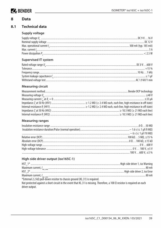
8.1 Technical data
Supply voltage
Supply voltage US DC 9 V…16 VNominal supply voltage DC 12 VMax operational current IS 300 mA (typ 185 mA)Max current IK 5 APower dissipation PS < 25 W
Supervised IT system
Rated voltage range Un DC 0 V…600 VTolerance +15 %Frequency range10 Hz…1 kHzSystem leakage capacitance Ce ≤ 1 µFWithstand voltage test AC 19 kV/1 min
Measuring circuit
Measurement method Bender DCP technologyMeasuring voltage Um ±40 VMeasuring current Im at RF = 0 ±33 µAImpedance Zi at 50 Hz (HV1) ≥ 12 MΩ (≥ 24 MΩ each, each line, high resistance in off state)Internal resistance Ri (HV1) ≥ 12 MΩ (≥ 24 MΩ each, each line, high resistance in off state)Impedance Zi at 50 Hz (HV2) ≥ 105 MΩ (≥ 21 MΩ each line)Internal resistance Ri (HV2) ≥ 105 MΩ (≥ 21 MΩ each line)
Measuring ranges
Insulation resistance range 0 Ω…50 MΩInsulation resistance duration/Pulse (normal operation)~ 16 s (≤ 1 µF/0 MΩ)
~ 6 s (≤ 1 µF/10 MΩ)Relative error (DCP) 100 kΩ…5 MΩ, ±15 %Absolute error (DCP) 0 Ω…100 kΩ, ±15 kΩHigh-voltage range 0 V…600 VHigh-voltage tolerance 0 V… 100 V, ±5 V 100 V…600 V, ±5 %
High-side driver output (iso165C-1)
HST_1* High-side driver 1, iso WarningMaximum current, Iout_max 80 mAHST_2* High-side driver 2, iso ErrorMaximum current, Iout_max 80 mA*External 22 kΩ pull-down resistor to chassis ground (KL31) is requiredNot protected against a short circuit in the event that KL31 is missing Therefore, a 100 Ω resistor is required on eachdriver output

40 iso165C_C1_D00154_06_M_XXEN / 03/2021
Data
Response values
iso165CResponse value Alarm 1 (Error) 30 kΩ…1 MΩ (default: 300 kΩ)Response value Alarm 2 (Warning) 40 kΩ…2 MΩ (default: 55 kΩ)
iso165C-1Response value Alarm 1 (Error) 30 kΩ…1 MΩ (default: 400 kΩ)Response value Alarm 2 (Warning) 40 kΩ…2 MΩ (default: 250 kΩ)
iso165C und iso165C-1Response uncertainty (according to IEC 61557-8) ±15 %Hysteresis +25 %Factor averaging Fave 1…10 (default: 3)Response time tan (DCP)(Changeover RF: 10 MΩ - Ran/2; at Ce = 1 µF; Un = DC 600 V)tan ≤ 20 s (at Fave = 10*) during self test tan +10 sMeasurement time after power on (and after HV relays are closed)≤ 3 s (< 1 µF/150 kΩ)Switch-off time tab (DCP)(Changeover RF: Ran/2 - 10 MΩ; at Ce = 1 µF; Un = DC 600 V)tab ≤ 40 s (at Fave = 10) during self test tab +10 s* Fave = 10 is recommended for electric vehicles
Interface
Protocol HS-CAN
iso165CData rate 250 kBaudTerminating resistance 124 Ω internally
iso165C-1Data rate 500 kBaudTerminating resistance None
Environment/EMC
EMC IEC 61326-2-4Overvoltage category/degree of pollution II/2Temperature range -40…+85 °CRange of application 5,000 m above sea level
Connectors (Tyco)
Receptacle housing type 1719183-1, 1719183-2, 1719183-3 (black, white, blue)Receptacle drawing number C-1719183Contact type (tin plated) 5-963715-1Contact wire range 0,50 - 0,75 mm2
Contact drawing number 929454Crimp hand tool 539635-1

iso165C_C1_D00154_06_M_XXEN / 03/2021 41
ISOMETER® iso165C + iso165C-1
Other
Operating mode Continuous operationDegree of protection IP5K0
Software versioniso165C V10 - Release S010 (VIFC: V50 , IMC V50)iso165C-1 V20 - Release S010 (VIFC: V100 , IMC V50)
Mounting
Recommended screws for mounting 4 x M5 (not included)Max tightening torque 225 ± 025 Nm (XX Ibs-in)
8.2 Ordering data
Type Response value range Nominalvoltage
Supplyvoltage
Art. No.
iso165C Alarm 1 (Error): 30 kΩ…1 MΩ (default: 300 kΩ);Alarm 2 (Warning): 40 kΩ…2 MΩ (default: 55 kΩ)
DC 0…600 V DC 12 V B91068175
iso165C-1 Alarm 1 (Error): 30 kΩ…1 MΩ (default: 400 kΩ);Alarm 2 (Warning): 40 kΩ…2 MΩ (default: 250 kΩ)
DC 0…600 V DC 12 V B91068176
8.2.1 Accessories
Type Art. No.
iso165C connecting kit B91068503

42 iso165C_C1_D00154_06_M_XXEN / 03/2021
Data
8.3 Standards - corresponding norms and regulations
8.3.1 General
IEC 61557-8 2007-01; IEC 60664-1 2004-04; ISO 6469-3 2001-11; ISO 23273-3 2006-11
8.3.2 EMC
CISPR 25; ISO 7637-2; ISO 11452-2; ISO 11452-4; ISO 11452-8; ISO 10605; IEC 61326-2-4; IEC 61000-4-4; E1 acc. to 72/245/EWG/EEC; ISO 16750-2
8.3.3 Environmental
ISO 16750-1; ISO 20653; ISO 16750-3; IEC 60068-2-14; IEC 60068-2-27; IEC 60068-2-32; IEC 60068-2-64; ISO 16750-4; IEC 60068-2-1; IEC 60068-2-2; IEC 60068-2-38; IEC 60068-2-60; IEC 60068-2-78
Normative exclusionThe device has gone through an automotive test procedure in accordance with multi customer require-ments as outlined by reg. ISO 16750-x. IEC 61557-8 will be fulfilled by creating an LED warning function and test button at the customer site if necessary.

iso165C_C1_D00154_06_M_XXEN / 03/2021 43
ISOMETER® iso165C + iso165C-1

iso16
5C_C
1_D0
0154
_06_
M_X
XEN
/ 03/
2021
/ ©
Bend
er G
mbH
& Co
KG,
Ger
man
y – Su
bject
to ch
ange
! The
spec
ified
stan
dard
s tak
e int
o acco
unt t
he ed
ition
valid
until
03/2
021 u
nles
s oth
erwi
se in
dicat
ed
Alle Rechte vorbehalten.Nachdruck und Vervielfältigungnur mit Genehmigung des Herausgebers.
Bender GmbH & Co. KGPostfach 1161 • 35301 Grünberg • DeutschlandLondorfer Str. 65 • 35305 Grünberg • DeutschlandTel.: +49 6401 807-0 • Fax: +49 6401 807-259E-Mail: [email protected] • www.bender.de
All rights reserved.Reprinting and duplicating
only with permission of the publisher.
Bender GmbH & Co. KGPO Box 1161 • 35301 Grünberg • Germany
Londorfer Str. 65 • 35305 Grünberg • GermanyTel.: +49 6401 807-0 • Fax: +49 6401 807-259
E-Mail: [email protected] • www.bender.de