Embed Size (px)
Citation preview
I so la t ion Break Excavat ion P lan
Countywide Recyc l ing and Disposal Fac i l i ty
Prepared for:
R e p u b l i c S e rv i c es o f Oh i o I I , L L CR e p u b l i c S e rv i c es o f Oh i o I I , L L CR e p u b l i c S e rv i c es o f Oh i o I I , L L CR e p u b l i c S e rv i c es o f Oh i o I I , L L C
3619 Gracemont Street, S.W. East Sparta, OH 44626
(330) 874-3855
Submitted by:
S C S E NG IN E E R S 2060 Reading Road, Suite 200
Cincinnati, OH (513) 421-5353
October 29, 2007 File No. 05206012
Offices Nationwide www.scsengineers.com
Adding value at every stop!™
R e p u b l i c S e r v i c e s o f O h i o I I , L L C
I S O LA T ION B R EAK E XCAVA T ION P L AN COUN TYW I D E R E CYC L I NG AND D I S PO SA L FA C I L I T Y
Prepared For:
R e p u b l i c S e r v i c e s o f O h i o I I , L L C dba Countywide Recycling and Disposal Facility
3619 Gracemont Street, S.W. East Sparta, OH 44626
Submitted By:
S C S E NG IN E E R S 2060 Reading Road, suite 200
Cincinnati, OH (513) 421-5353
October 29, 2007 File No. 05206012
i
T a b l e o f C o n t e n t s Section Page
1 Introduction.............................................................................................................................................. 1-1
2 Site and Project Background ............................................................................................................... 2-1
Site Setting and History ..................................................................................................................2-1
Isolation Break Rationale................................................................................................................2-2 Extent of Reaction in Proposed Isolation Break Area .......................................................2-2 Feasibility of Waste Relocation ............................................................................................2-3 Isolation Break Components...................................................................................................2-4 Stability Analysis......................................................................................................................2-4
3 Site Preparation..................................................................................................................................... 3-1
Soil cover ...........................................................................................................................................3-1
Gas System Components ................................................................................................................3-2
Storm Water Management............................................................................................................3-2 Diversion Berms and Ditches ..................................................................................................3-2 Temporary Management Area .............................................................................................3-2 Solid Waste Disposal Area ...................................................................................................3-2
4 Waste Removal and Relocation.......................................................................................................... 4-1
Operational Criteria .......................................................................................................................4-1 Limited Access to Excavation Area .......................................................................................4-1 Limited Access to Disposal Areas ..........................................................................................4-2 Alternate Access to Excavation .............................................................................................4-2 Daily Tailgate Meetings .........................................................................................................4-2 Equipment..................................................................................................................................4-2
Excavation Site: ............................................................................................................ 4-2 Disposal Area Working Face: ................................................................................... 4-3 Miscellaneous Equipment: ........................................................................................... 4-3
Personnel ...................................................................................................................................4-3 Inclement Weather ..................................................................................................................4-3 Litter Control .............................................................................................................................4-4 Daily Records............................................................................................................................4-4 Inspections .................................................................................................................................4-5 Daily Cover...............................................................................................................................4-5 Alternate Daily Cover.............................................................................................................4-5 Intermediate Cover..................................................................................................................4-6 Transitional Cover....................................................................................................................4-6 Leachate Outbreaks................................................................................................................4-6 Landfill Gas Threshold Exceedances....................................................................................4-6
Waste Excavation............................................................................................................................4-6 Direction of Excavation Progression .....................................................................................4-7 Solid Waste Disposal Operational Criteria .......................................................................4-7 Odor Issues................................................................................................................................4-7 Contingency Issues ...................................................................................................................4-7
Management of Excavated Aluminum Waste ............................................................................4-8
Management of Impacted Solid Waste ......................................................................................4-9
T a b l e o f C o n t e n t s , C o n t i n u e d
C o u n t y w i d e R D F i i I s o l a t i o n B r e a k E x c a v a t i o n P l a n
Isolation Zone Excavation ...............................................................................................................4-9
Isolation Zone Backfill .................................................................................................................. 4-10
Collection Drain ............................................................................................................................. 4-10
Replacement of Gas Collection Wells ...................................................................................... 4-10
Schedule.......................................................................................................................................... 4-11
5 Storm Water Management.................................................................................................................. 5-1
6 Odor Control Measures ........................................................................................................................ 6-1
Current Odor Control Procedures.................................................................................................6-1
Waste Excavation Issues.................................................................................................................6-1
Proposed Odor Control Measures................................................................................................6-1 Waste Cover ............................................................................................................................6-1 Landfill Gas Control System ..................................................................................................6-2 Odor Neutralization System..................................................................................................6-2
7 Performance Monitoring ....................................................................................................................... 7-1
L i s t o f A p p e n d i c e s
No.
Appendix A Boring Logs Appendix B Stability Analysis Appendix C ADC Product Information
L i s t o f F i g u r e s No.
Figure 1 Plan View, Existing Conditions Figure 2 Cross Section, Existing Conditions Figure 3 Photograph of Supersacks at Cell 7 Working Face Figure 4 Excavation Area Overview Figure 5 Excavation Plan Figure 6 Excavation Cross Section Figure 7 Excavation Drain Profile Figure 8 Excavation Details Figure 9 Landfill Gas Collection System Modifications Figure 9a Details - Landfill Gas Collection System Modifications Figure 9b Details - Landfill Gas Collection System Modifications Figure 10 Waste Relocation and Traffic Routes
R e p u b l i c S e r v i c e s o f O h i o I I , L L C
C o u n t y w i d e R D F 1 - 1 I s o l a t i o n B r e a k E x c a v a t i o n P l a n
1 INTRODUCT ION
Countywide Recycling and Disposal Facility (Countywide) is a fully lined Subtitle D solid waste
landfill located in Stark County, Ohio. Countywide is owned and operated by Republic Services
of Ohio II, LLC (Republic). Countywide is permitted and licensed to accept solid waste as
defined in the Ohio Revised Code. Countywide has been in operation since 1991. Countywide
was owned and operated by another solid waste company until February 1999, when it was
purchased by Republic. The facility was designed and constructed with state-of-the-art
engineered systems to protect the environment, including composite liner system, leachate
collection system, and landfill gas collection and control system (GCCS).
The purpose of this document is to propose an alternative isolation break in a different location
than the location between Cells 8A and 8B that was selected by the Director as an interim
remedial action. This Isolation Break Excavation Plan provides a work plan for the excavation
of in-place waste material, down to an existing cell separation berm situated between Cells
5B/5C and Cell 7, to provide an Isolation Break which will eliminate the potential for the
migration of the reaction from the initial 88-acre area into the adjacent cells at the facility. Upon
completion, this break would effectively prohibit the potential for migration of the reaction to the
northern expansion area from within the original 88 acres. There is currently strong monitoring
evidence that soon after the implementation of this isolation break, it will be possible to deem the
break between Cells 8A and 8B unnecessary. This submittal is intended to provide details
regarding this additional, and ultimately alternative, interim remedial action. This Plan includes
details of the site preparation, excavation of waste material, modifications to the gas collection
and control system, and performance monitoring.
The following is a brief summary of the contents of this plan:
� A brief description of the Countywide facility and the project history is presented in
Section 2 below, including the evaluations performed to demonstrate that the construction
of the isolation break is feasible.
� Section 3 presents the site preparation procedures necessary to construct the Isolation
Break.
� Section 4 describes the removal and relocation of the waste materials associated with the
construction of the Isolation Break.
� Section 5 addresses storm water run-off and run-on management during the excavation of
the Isolation Break to minimize the generation of leachate and control erosion.
� Section 6 presents odor control measures to be employed during excavation and
relocation of the waste materials.
� Section 7 contains the criteria for post-construction monitoring to confirm that the
reaction has not migrated beyond the Isolation Break.
R e p u b l i c S e r v i c e s o f O h i o I I , L L C
C o u n t y w i d e R D F 2 - 1 I s o l a t i o n B r e a k E x c a v a t i o n P l a n
2 S I T E AND PROJECT BACKGROUND
S I T E S E T T I N G A N D H I S TOR Y
Solid waste landfills in Ohio are permitted to accept household waste, commercial waste, and
non-hazardous industrial waste. Countywide estimates that it accepted approximately 600,000
tons of non-hazardous aluminum process waste between 1993 and 2006. The majority of this
aluminum process waste was described as “dross” or “salt cake”, which are by-products of the
melting of aluminum with a salt flux. A small portion of the aluminum process waste was
baghouse dust and shredder/delaq fines.
Historically, Countywide’s landfill gas (LFG) collection system operated as expected. Prior to
late 2005, the LFG well data were typically within expected ranges for normal waste
decomposition and LFG production. By late 2005, Countywide had identified LFG wells with
higher than expected temperatures. Around that same time, an increase in odor complaints
occurred.
In response to the odor complaints, Countywide voluntarily expanded the gas collection and
control system (including installing additional wells and flare capacity) and installed an odor
control system. In addition, Countywide constructed approximately 3 acres of temporary HDPE
geomembrane cap over the south slope impacted area.
In addition to the voluntary actions described above, the Ohio Environmental Protection Agency
(OEPA) issued Directors Findings and Orders on September 6, 2006 aimed at addressing odor
issues. By December 16, 2006, Countywide had complied with all the orders. This included
installing enhancements to the LFG collection system in the area where high temperatures had
been identified. In addition, Countywide voluntarily constructed approximately 30 acres of
HDPE geomembrane cap over the impacted area. These improvements have been successful in
reducing fugitive emissions, reducing oxygen and water movement into the landfill, and virtually
eliminating the associated odors.
In addition to the temperatures and odors, substantial settlement was observed in a specific
portion of the landfill. This has resulted in settlement in the landfill surface and has required
monitoring and repair of the intermediate cover and the temporary HDPE geomembrane cap that
was installed. Countywide also observed changes in the landfill gas composition, including a
decrease in methane, an increase in carbon monoxide, and increased hydrogen concentrations.
The OEPA and Countywide entered into a second set of F&Os dated March 28, 2007. Under the
F&Os, Countywide agreed to prepare and submit a Fire Suppression Plan (FSP) no later than 60
days from March 28, 2007. The F&Os specify that four remedial alternatives be evaluated in the
FSP, including application of a magnesium chloride solution, application of specialty foams,
excavation of the wastes, and additional capping.
This plan identifies a remedial effort that will create a break between the area known to be
involved in the reaction (portions of the original 88 acres), and the expansion area where no
signs of reaction exist today (Cell 7 and beyond).
R e p u b l i c S e r v i c e s o f O h i o I I , L L C
C o u n t y w i d e R D F 2 - 2 I s o l a t i o n B r e a k E x c a v a t i o n P l a n
I S OL A T I O N B R EA K R A T I ON A L E
Countywide has designed an isolation break between Cells 5 and 7 that satisfies the intent of the
OEPA to create a preventative isolation break designed to ensure the reaction does not move
northward into the expansion areas. The isolation break consists of an excavation of
approximately 385,000 cubic yards of waste that can be completed in about 2-3 winter months
and accomplishes the preventative break without permitting the reaction to move into any
portions of the northern expansion.
E x t e n t o f R e a c t i o n i n P r o p o s e d I s o l a t i o n B r e a k A r e a
One concern that has been expressed by the OEPA is the possibility that the reaction has
progressed into the area of the proposed excavation. The OEPA concerns were based on
elevated wellhead gas temperatures and carbon monoxide concentrations in the landfill gas at
wells located on the north of the reaction. In an effort to address concerns of the OEPA,
Countywide has conducted a focused field investigation and an evaluation of the data collected
under the field investigation and the Findings and Orders. The investigation and evaluation
show that the reaction has not progressed into the proposed excavation area.
The field investigation included test borings and the installation of thermistors in those test
borings to measure solid waste temperatures in the area of the excavation. Five sonic boreholes
were advanced within the edge and just outside of the southeast corner of the proposed
excavation. The boring locations are shown on Figure 1. Logs of the borings are contained in
Appendix A. These boring locations were selected because this portion of the excavation is the
closest to the area of the original 88 acres that is undergoing reactions. The borings were
continuously sampled to approximately 15 feet above the liner. Thermistors or vibrating wire
pressure transducers that can also measure temperature were installed at selected depths in these
borings.
Visual observations of the core samples by Countywide’s subcontractor (Alex Tassos of SCS
Engineers) and by OEPA personnel confirmed no signs of reaction in the area of the proposed
excavation. No zones of charred or reacted waste were observed. The waste was in a condition
typical of waste of this age and burial depth.
Countywide believes that the higher landfill gas temperatures and CO concentrations near the
proposed excavation, as shown on Figure 1, are due to the heat and reaction gasses that migrate
away from, or project outward from, the area where the reactions are actually occurring. These
processes are illustrated on the cross section A-A, which is shown as Figure 2. Countywide
believes that heat generated by the reactions in the aluminum waste and potentially by the
secondary reactions in the solid waste adjacent to the aluminum waste migrates away primarily
by convection in the shallow waste, by the movement of steam and heated landfill gas. The heat
migrates primarily by conduction in the deeper waste, which has been more densely compacted
and is less permeable.
CO migrates away from the reaction area due to a combination of a pressure gradient and a
concentration gradient. The cross section (Figure 2) shows that the CO can migrate beyond
R e p u b l i c S e r v i c e s o f O h i o I I , L L C
C o u n t y w i d e R D F 2 - 3 I s o l a t i o n B r e a k E x c a v a t i o n P l a n
landfill gas collection wells, given the shallow depth of the wells’ zones of influence and the
potential that the zones of influence of adjacent wells may not overlap.
Very recent monitoring in Cell 7 gas extraction wells has demonstrated that the reaction has not
progressed into Cell 7 and, in fact, the projection of elevated CO and temperature has not yet
advanced north of the southern limit of Cell 7. See Figure 1 which shows that wells PW-306, -
313, -314, -325, -326, and -318 all have wellhead temperatures, downhole temperatures, and CO
in normal operating levels.
Therefore, based on visual observation of waste samples from test borings, field measurements
of wellhead temperature and waste temperature within the expected ranges, and laboratory
analyses of carbon monoxide and hydrogen, Countywide is confident that the reaction has not
progressed into the proposed excavation area or into Cell 7. Consequently, the excavation can be
performed without complication, and, upon completion, will successfully create a complete
break between the reaction(s) occurring in the 88-acre area and the expansion area to the north.
F e a s i b i l i t y o f Wa s t e R e l o c a t i o n
Excavation and relocation of waste material is not an unprecedented activity in Ohio. Several of
these projects involved hundreds of thousands of cubic yards of waste relocation. This project
involves the relocation of approximately 385,000 cubic yards of waste material. Sections 3 and
4 below describe the site preparation and waste excavation activities.
Site records indicate that the acceptance of all dross or salt cake type wastes stopped prior to the
disposal of waste in Cell 7, therefore, Countywide does not anticipate encountering any dross or
salt cake type aluminum waste during the excavation. However, small quantities of fabric bags
of waste consisting of baghouse dust collected from the furnace exhaust stacks or shredder/delaq
fines collected from the process that shreds recycled aluminum beverage cans and removes the
lacquer coating from the inside of the cans are potentially present in the area. Both of these
materials were delivered to the site in “super sacks”. Super sacks are large square fabric bags
that can contain from 2,000 to 3,000 lbs of material. Figure 3 shows examples of the super sacks
that have been unloaded at the working face.
Health and safety procedures and precautions are described in a stand alone document. The
primary risk is the potential for a landfill gas fire. As with any waste excavation project, it is not
anticipated that sufficient quantities of landfill gas, above that which can be diluted below the
lower explosive limit by normal air movement, will accumulate except near the surface of
exposed waste. As discussed in the project Health and Safety Plan (to be submitted separate
from this Isolation Break Plan), appropriate monitoring will be performed to protect the
equipment operators from both flammable and toxic gasses. The appropriate plans and materials
will be on hand to deal with landfill gas and/or surficial waste fires. Plans have been prepared to
deal with unlikely or unanticipated risks and are described in this Plan.
As described above, the data collected from the 88-acre area indicates that the reaction has not
moved to or beyond the limits of this proposed excavation, making this excavation plan a
feasible alternative. Ongoing visual inspection of the operation will be conducted to confirm that
the reaction has not progressed north of the excavation and that the excavation can be completed
R e p u b l i c S e r v i c e s o f O h i o I I , L L C
C o u n t y w i d e R D F 2 - 4 I s o l a t i o n B r e a k E x c a v a t i o n P l a n
safely. Upon completion of this isolation break, Countywide will make a demonstration that the
reaction has not progressed into Cell 7 based on the criteria described in Section 8. Having
accomplished that, the isolation break constructed at the 8A/B interface would no longer be
needed and normal filling operations could resume in that area.
I s o l a t i o n B r e a k C omp o n e n t s
The excavation described in this Plan will provide a complete break between waste in the 88 acre
area and waste in Cell 7 and the northern expansion area. As shown on Figures 4 through 6, this
will be accomplished by total removal of waste down to the top of an existing berm that
separates the two areas within the excavation area.
This Isolation Break Excavation Plan (Plan) describes the procedures proposed by Countywide
to install the isolation break. This section of the plan covers the excavation of waste, application
of interim cover over exposed waste, collection of landfill gas, management of storm water
events, collection of leachate, odor control, contingency issues, and safety issues associated with
the implementation of this alternative interim remedial action to address the potential for the
migration of the reaction from the initial 88-acre area into the adjacent cells at the facility.
S t a b i l i t y A n a l y s i s
The stability of the landfill slopes resulting from the proposed Isolation Break waste relocation
has been evaluated. The southern slope will be a 3:1 and the northern slope will be a 2.75:1.
The evaluation, presented in Appendix B, included analysis of the impact of elevated pore
pressures and an analysis of the potential reduction in waste shear strength on the stability of the
north face of Cell 4 and 5 formed as a result of the Isolation Break excavation. The stability
analysis demonstrates that the proposed slope configuration with the drainage provided will
remain stable even under the development of adverse conditions. The safety factors for both the
southern and northern slopes is 1.5. It should also be noted that in the event any instability is
identified on the north slope of Cells 4 and 5 in the Isolation Break area, additional soils could be
added to create a stabilizing berm, as was done on the south side of the 88 acres. As
recommended in Appendix B, if signs of slope movement are observed or temperatures in the
gas wells within the limits of the Isolation Break slope exceed 170 ºF a surface monitoring
program will be established to determine the rate of movement and allow the need to construct a
stabilizing berm to be evaluated.
R e p u b l i c S e r v i c e s o f O h i o I I , L L C
C o u n t y w i d e R D F 3 - 1 I s o l a t i o n B r e a k E x c a v a t i o n P l a n
3 S I T E PREPARAT ION
The following sections outline the steps that will be taken to prepare the area for excavation.
Site preparation will include the following activities:
1. Removal of soil cover and stockpiling for reuse. Soil removal will be phased to minimize
the exposure of waste. Exposed waste area will be kept to less than 2 acres if possible.
Soil will be stockpiled on both the north and south sides of the excavation area for
contingency use, or used immediately in the active area as daily cover.
2. Relocation of gas collection system header lines within the excavation zone and
preparation of gas collection wells and laterals for abandonment or reduction in collection
vacuum.
3. Grouting of gas collection wells in the excavation area that are to be abandoned to
prevent air intrusion into the landfill.
3. Construction of storm water diversion berms and/or ditches to prevent storm water run-on
into and run-off from the excavation zone from surrounding areas where possible.
4. Preparation of the temporary storage area for aluminum containing bagged dust waste
materials encountered during excavation.
5. Preparation of the disposal area in Cells 7 and 8A. A filling plan will be developed for
disposal of excavated material in Cells 7 and 8A. These areas will be staked and
prepared to accept the waste material.
6. Preparation of the odor control system as described in Section 6 below.
S O I L C OV ER
The area where waste is to be excavated is currently covered by an intermediate soil cover
approximately 2 feet thick. The soil will be stripped in phases to minimize waste exposure to
rainfall events and to control odors. The area to be stripped of cover soil will be limited to that
which is necessary to allow waste removal on a daily basis. Exposed waste area will be kept to
less than 2 acres if possible. With the exception of the active excavation area, areas that are
stripped of cover soil will be re-covered with daily cover soil or alternate daily cover (ADC) to
promote odor control and positive drainage from the area.
Soil stripped from the excavation zone may be stockpiled nearby for reuse as daily cover and to
serve as a fire suppressant in the event that waste is encountered that exhibits evidence of
ongoing combustion. The soil may also be used to construct storm water diversion berms at the
top of the excavation area to prevent storm water run-off into the excavation, or as daily cover in
the active area of the landfill.
R e p u b l i c S e r v i c e s o f O h i o I I , L L C
C o u n t y w i d e R D F 3 - 2 I s o l a t i o n B r e a k E x c a v a t i o n P l a n
G A S S Y S T E M C O MP ON E N TS
It is anticipated that one gas collection system header line will need to be relocated from the
excavation zone to maintain the integrity of the system. The header line will be relocated outside
the excavation zone as shown on Figure 9 and then re-connected to the collection system to
avoid disruption to gas collection. Additional header lines may be added to connect new gas
collection wells to the system.
Several gas collection wells will be impacted by the excavation of the Isolation Break. Vacuum
to the wells in or near the excavation area may be reduced during construction to minimize the
possibility of drawing air into the waste mass. Wells within the excavation area that are no
longer useable, due to potential air intrusion, will be decommissioned by fully grouting the well
casing. This will eliminate the potential vertical oxygen transmission during excavation.
Vacuum will be maintained at the wells near the final excavation limits until such time as the
excavation comes within 100 ft of the well or monitoring indicates any abnormal risk of air
intrusion. Changes or reductions in vacuum will be managed by the project team as the
excavation progresses.
S TOR M W A T ER M A N A G EM E N T
D i v e r s i o n B e rm s a n d D i t c h e s
Clean cover soil removed from the excavation area will be reused to provide storm water
diversion berms adjacent to the excavation zone to minimize surface water run-off into the
excavation where waste will be exposed. The diversion berms will be supplemented, as
necessary, with diversion ditches to reroute surface water flow to the storm water management
system and prevent flow into the excavation zone.
T emp o r a r y Ma na g eme n t A r e a
A temporary management area will be established for the small quantities of aluminum
containing waste that are removed from the Isolation Break Excavation area. The temporary
management area will be designed to provide storm water run-on and run-off controls to prevent
negative impacts to the facility storm water management system and surrounding surface waters.
Berms and/or ditches will be constructed to divert storm water run-on away from the temporary
management area. Containment berms will prevent storm water that comes in contact with the
aluminum containing waste from being discharged into the facility storm water management
system. Any water that comes into contact with the aluminum waste will be transferred into the
leachate collection system or transported off site for treatment if that water cannot be placed in
the leachate collection system.
S o l i d W a s t e D i s p o s a l A r e a
Solid waste from the excavation area will be disposed in Cell 7 and Cell 8A as shown on Figure
10. Preparation of the disposal area may include stripping soil cover, construction of diversion
berms and/or ditches, and modifications to the existing storm water controls to incorporate the
newly placed waste into the overall site management system. Access to the disposal location
R e p u b l i c S e r v i c e s o f O h i o I I , L L C
C o u n t y w i d e R D F 3 - 3 I s o l a t i o n B r e a k E x c a v a t i o n P l a n
from the Isolation Break will be across cells 7 and 8A of the landfill, in lieu of access from the
all-weather roads that serve the current landfill operations. Avoiding conflict between
excavation vehicles and incoming landfill trash trucks will speed the excavation process,
promote a safer operation, and not interfere with the daily landfill operations. Equipment used to
excavate and transport waste from the Isolation Break will be independent of the landfill
operations equipment.
R e p u b l i c S e r v i c e s o f O h i o I I , L L C
C o u n t y w i d e R D F 4 - 1 I s o l a t i o n B r e a k E x c a v a t i o n P l a n
4 WASTE REMOVAL AND RE LOCAT ION
Waste removal and relocation activities include the following activities:
1. Excavation of waste material with heavy equipment, including characterization of the
waste for the various disposal options.
2. Excavation of waste material in the isolation zone area.
3. Segregating aluminum waste and/or reacted solid waste.
4. Relocating solid waste.
5. Management of storm water and leachate.
6 Management of blowing litter.
7 Odor control activities.
8. Relocating aluminum waste materials (if encountered) to a separate, temporary
management area for treatment prior to disposal.
9. Installing liquid/gas collection trench near base of excavation.
10. Placement of daily cover or ADC, intermediate cover, and transitional cover over the
excavated areas.
11. Final grading of temporary slopes.
12. Installation of replacement gas collection wells.
O P ER A T I O N A L C R I T ER I A
L im i t e d A c c e s s t o E x c a v a t i o n A r e a
The exclusion zone for this project includes those areas within the limits of excavation as shown
on Figure 5 where waste is exposed and where the waste has received daily cover or ADC. Only
authorized personnel will be permitted in the exclusion zone during this project. All other
personnel will be excluded. Disposal areas, areas of the excavation where intermediate cover has
been applied to the waste, material storage areas, stockpile areas, equipment staging areas, and
other areas outside the limits of waste excavation are not considered part of the exclusion zone.
solid waste will be exposed in the excavation area and certain precautions required by the site
Health and Safety Plan will be implemented to ensure the safety of the workforce in the area of
exposed waste. The project Health and Safety Plan (to be provided as a separate document) will
describe the potential hazards, the precautions necessary, and training needed by personnel
permitted to enter the exclusion zone. Only personnel that meet the requirements of the project
Health and Safety Plan will be permitted in the exclusion zone. Visitors will not be permitted in
the exclusion zone, unless they have read and agree to comply with the requirements of the
R e p u b l i c S e r v i c e s o f O h i o I I , L L C
C o u n t y w i d e R D F 4 - 2 I s o l a t i o n B r e a k E x c a v a t i o n P l a n
project Health and Safety Plan, have been authorized by Countywide, and are accompanied at all
times by a Countywide representative. Visitors must sign in upon arrival and sign out upon
departure from the site.
Those portions of the excavation area will be considered an exclusion zone until such time as any
exposed waste has been covered with a minimum of two feet of soil (transition cover). As the
final grades in the excavation area are reached, soil cover will be placed over the waste to
minimize leachate production, minimize methane migration and odor issues, and allow the
installation of replacement gas collection wells. Please not that the exclusion zone will change
form day to day as the excavation progresses, and will be defined by the Project Health & Safety
Officer.
L im i t e d A c c e s s t o D i s p o s a l A r e a s
Disposal areas identified for the final disposal of solid waste excavated from the Isolation Break
will not be considered a part of the exclusion zone for this project. See Figure 10 for the location
of the solid waste disposal area. Precautions, access restrictions, and safety measures employed
in typical waste disposal activities will apply to the waste disposal areas.
A l t e r n a t e A c c e s s t o E x c a v a t i o n
Primary and alternate access routes to and from the work areas shall be provided to ensure
emergency ingress and egress is maintained at all times. Access to the excavation is provided by
all-weather roads suitable for travel by emergency vehicles via the western perimeter road and
the eastern access road, should the need arise.
Da i l y T a i l g a t e M e e t i n g s
Daily tailgate meetings will be conducted at the site to discuss health and safety issues, daily
work plans, issues that need to be addressed from the previous day’s activities, etc. These
meetings will be attended by all personnel working on this project at the beginning of each shift.
E q u i pm en t
The minimum equipment contemplated for the implementation of this plan is provided below.
Excavators, bulldozers, compactors, trucks, and earthmovers will have enclosed cabs with
pressurized and filtered air circulation systems capability where necessary.
The following equipment will be anticipated to perform the tasks described in the Isolation Break
Excavation Plan:
Excavation Site:
2 - tracked excavators
2- waste handling track-type tractors
4 –off-road dump trucks
R e p u b l i c S e r v i c e s o f O h i o I I , L L C
C o u n t y w i d e R D F 4 - 3 I s o l a t i o n B r e a k E x c a v a t i o n P l a n
1 –backhoe loader with hoe pac
Disposal Area Working Face:
2 - landfill compactors
1 - track–type tractor
1 - waste handling track-type tractor
Miscellaneous Equipment:
1- Water wagon (for standby only)
1 – Motor grader
2 – portable odor control spray systems
Other site equipment as needed
Equipment capable of dispensing water for fire fighting purposes, for example a water wagon,
will be on stand site the at all times during excavation of the waste.
P e r s o n n e l
All personnel entering the exclusion zone will meet the minimum training requirements
described in the Health and Safety Plan. Visitors must read and acknowledge compliance with
the conditions of the Health and Safety Plan and be accompanied by a Countywide representative
while in the exclusion zone.
I n c l eme n t W e a t h e r
Contingency plans for dealing with inclement weather include, but are not limited to the
following activities:
• A heavy rainfall or snowfall event may be cause for implementation of a contingency action.
The intensity of the rainfall event will dictate whether or not excavation operations are shut
down. If precipitation shuts down operations for a minimum of ½ day, the exposed waste
should be covered the same as it would be at the end of a working day. Daily cover must be
applied in the form of soil cover, foam ADC, cement-mortar coating, or tarps that are
currently approved for use at the site or approved for use as a part of this Isolation Break
Excavation Plan. An ample supply of soil to be used as daily cover will be available at all
times adjacent to the excavation area. Soil should be used to cover exposed waste due to
inclement weather when the rainfall intensity exceeds manufacturer’s recommendation for
application of the foam ADC. Tarps may be used to supplement soil cover or foam ADC
when necessary. Cement-mortar ADC may also be used to supplement soil cover. Rainfall
shortens the life expectancy of the foam ADC; however it is less affected by snowfall. If
foam is used prior to a rainfall event, the effectiveness of the foam cover will be inspected
daily and replaced or replenished as necessary.
R e p u b l i c S e r v i c e s o f O h i o I I , L L C
C o u n t y w i d e R D F 4 - 4 I s o l a t i o n B r e a k E x c a v a t i o n P l a n
• Heavy rainfall may also require implementation of contingency measures to manage storm
water and leachate. Storm water that has not come into contact with the exposed waste will
be directed to the site’s storm water management facilities via diversion dikes, berms,
ditches, and temporary piping. Leachate that is generated in the excavation area will be
managed through the construction of dikes and diversions berms to temporarily store the
leachate within the limits of the waste excavation, to be pumped into appropriate containment
vessels for transport to the site’s leachate management facilities for proper disposal.
• Freezing weather conditions during the excavation are anticipated and may require additional
care for worker safety when moving and disposing of waste, hauling daily soil cover,
receiving materials from off-site, worker safety, stockpiling cover soil, and storm water
management. Site personnel will be trained regarding the added dangers associated with
working on frozen ground, moving frozen waste and soil, icy conditions on roadways and
materials, and health issues. Daily tailgate meetings will address these issues when
appropriate.
• Wet loads of excavated waste will be managed with operational procedures that are typical
with standard landfill methods. Tailgates of the off-road dump trucks will be banked with
soil as necessary to eliminate spillage on the access roads to the disposal area. Wet loads will
be minimized by mixing wet waste with drier waste or soil prior to placement on the truck,
whenever possible.
L i t t e r C o n t r o l
As with normal landfilling operations, control of blowing litter will be accomplished through the
application of daily cover, operational plans that consider the direction of the prevailing winds,
and portable litter fences where necessary. With excavation proceeding from west to east and
north to south, portable litter fences will be erected on the downwind north and east sides of the
excavation as necessary to trap litter being blown from the working face or loaded trucks.
Additionally, regular patrols of the area outside the exclusion zones by “paper pickers” will be
conducted as needed, using on-site personnel.
Da i l y R e c o r d s
Logs of the excavation process will be completed on a daily basis. The logs will include
information about how much waste was moved, which cell it was moved to and the general
location within the cell, how it was disposed of, if any aluminum containing waste was
encountered, weather conditions, problems experienced and remedies, and general condition of
the waste excavated. The daily logs will include a section dedicated to the identification of any
waste that observed to have been impacted by the reaction. The logs will be compared to the
observations and logs made by OEPA representatives so that concurrence can be documented or
differences of opinion can be identified.
In addition, photographic and video documentation will be used. In notable areas (where it
appears special conditions exist or reaction symptoms may be present), GPS will be used to
correlate observations and photo records to physical location and for potential future re-
inspection or verification of observations.
R e p u b l i c S e r v i c e s o f O h i o I I , L L C
C o u n t y w i d e R D F 4 - 5 I s o l a t i o n B r e a k E x c a v a t i o n P l a n
I n s p e c t i o n s
Daily inspections of the waste excavation site will be conducted to identify issues that need to be
addressed, including the following:
• Evidence of fire, heat-impacted waste, or reaction-impacted waste
• Daily cover thickness
• Blowing litter
• Odors
• Storm water management
• Access and haul road conditions
• Fugitive dust emissions
• Leachate outbreaks
• Erosion
• Ponding on the waste mass
• Landfill gas emissions
The issues noted on the daily log forms will be discussed at the next tailgate meeting, where a
plan will be developed to address the inspection issues.
Da i l y C o v e r
With the exception of the active excavation area, areas that are stripped of cover soil will be re-
covered with daily cover soil or alternate daily cover (ADC) to promote odor control and
minimize the generation of leachate from rainfall events.
Soil daily cover will be used where appropriate to minimize the generation of leachate as a result
of infiltration, control odors, discourage rodents and vectors, and control blowing litter. Soil to
be used for daily cover will be obtained from stripping the excavation area and other borrow
sources on site.
A l t e r n a t e D a i l y C o v e r
Alternate daily cover (ADC) will be used where steep slopes or weather conditions do not permit
the application of consisting of aqueous foam, cement-mortar, or tarps (see note above) soil daily
cover. ADCs being considered for this project include:
� aqueous foam (Rusmar or equal),
R e p u b l i c S e r v i c e s o f O h i o I I , L L C
C o u n t y w i d e R D F 4 - 6 I s o l a t i o n B r e a k E x c a v a t i o n P l a n
� cement-mortar (Posi-Shell or equal),or
� tarps (currently approved or equal, see note above)
Information on the Rusmar and Posi-Shell ADCs and related application equipment is provided
in Appendix C.
Approval of this plan will enable Countywide to use some or all of the above ADCs, in whatever
quantity required for this project. The use of ADCs not already approved will not apply to Cell
8B or beyond. Selection of soil cover or an ADC for this project will be determined in the field
on a daily basis.
I n t e rm e d i a t e C o v e r
Final excavation slopes will be covered with a minimum 12-inch thick layer of intermediate
cover soil within 30 days of completion of the excavation. Intermediate soil material and
application procedures will be in accordance with the site’s authorizing document.
T r a n s i t i o n a l C o v e r
Transitional cover, consisting of an additional 12 inches of soil will be installed over the
excavation slopes within 60 days of completion of the excavation. Transitional soil material and
application procedures will be in accordance with the site’s authorizing document.
L e a c h a t e O u t b r e a k s
If encountered, leachate outbreaks on the face of the excavation slopes will be managed in
accordance with the site’s authorizing document by containing, collecting, and disposing, and
minimizing, controlling, or eliminating the conditions which contributed to the production of
leachate.
L a n d f i l l G a s T h r e s h o l d E x c e e d a n c e s
An exceedance of the landfill gas threshold established by the Health and Safety Plan, at any
time, may be cause for suspension of operations in that area until the cause can be determined
and concentration lowered to acceptable levels or other adjustments are made in operating
procedures to mitigate risks to the satisfaction of the Health and Safety Manager. Refer to the
Health& Safety plan for further details.
W A S T E EX C A V A T I ON
Following removal of the soil cover, waste excavation will begin with heavy construction
equipment. The waste will be excavated with a track backhoe and loaded into off-road dump
trucks for transport to the designated disposal area. Solid waste not containing aluminum waste
products will be trucked to the prepared disposal areas within the existing Cells 7 and 8A limits
of waste placement (see Figure 10).
R e p u b l i c S e r v i c e s o f O h i o I I , L L C
C o u n t y w i d e R D F 4 - 7 I s o l a t i o n B r e a k E x c a v a t i o n P l a n
Waste excavation will progress from west to east along the centerline shown on the attached
drawings. The south excavation slope will be excavated on a slope of 3 feet horizontal to 1 foot
vertical (3:1) and the north excavation slope will be excavated on a slope of 2.75 feet horizontal
to 1 foot vertical (2.75:1) down to the elevation approximately 10 feet above the base liner on top
of the berm dividing Cell 7 from the cells to the south. At this elevation, an excavation will
proceed down to the liner surface using 1:1 slopes, as shown in Figures 6 and 8. The zone
excavated down to the liner will be backfilled with clay soils and a drainage zone will be created
on the south facing edge of the backfill (see Figure 8).
Daily cover consisting of soil, foam, tarps (see note above), or other alternate daily cover
material will be placed over the excavated areas if work is to be suspended in that area for more
than 8 hours. Vertical or near vertical interim excavation slopes will be sealed using an aqueous
foam or other spray-on alternate daily cover material to provide gas and odor control. Upon
reaching the desired final grade, an intermediate cover soil with a minimum thickness of one foot
will be applied within 30 days. An additional minimum 12 inches of transitional cover soil will
be applied within 60 days of reaching final grade.
D i r e c t i o n o f E x c a v a t i o n P r o g r e s s i o n
Excavation of the Isolation Break will commence in the northwest corner of the area identified
on the drawings and proceed in a north to south and west to east direction. It is envisioned that
the excavation operation will consist of the removal of waste in approximately 15-18 foot
horizontal layers starting on the north slope of the excavation. Exposed waste area will be kept
to less than 2 acres if possible to reduce leachate generation and control odor.
S o l i d W a s t e D i s p o s a l O p e r a t i o n a l C r i t e r i a
Solid waste that is excavated from the Isolation Break will be transported to Cell 7 and 8A, as
shown on Figure 10, to be disposed of permanently. The area to receive the relocated waste will
be prepared by stripping any soil cover, constructing storm water management facilities required
to minimize run-on and run-off, using leachate management facilities necessary to contain
leachate within the disposal area, and applying erosion control measures required by the site’s
authorizing document.
Odo r I s s u e s
It is anticipated that odors will be created for the duration of this project. Countywide will
minimize the odors primarily through prompt placement of cover as practical Countywide will
also utilize existing odor neutralizing system and portable systems that can be moved close to the
source of the odors to contain or neutralize the odors.
Co n t i n g e n c y I s s u e s
Generally, unexpected events that occur during excavation of the Isolation Break can be
managed utilizing standard landfill operating practices. The exception could be the discovery of
smoldering waste, aluminum dross, or salt cake and, at this time, there is no evidence of any of
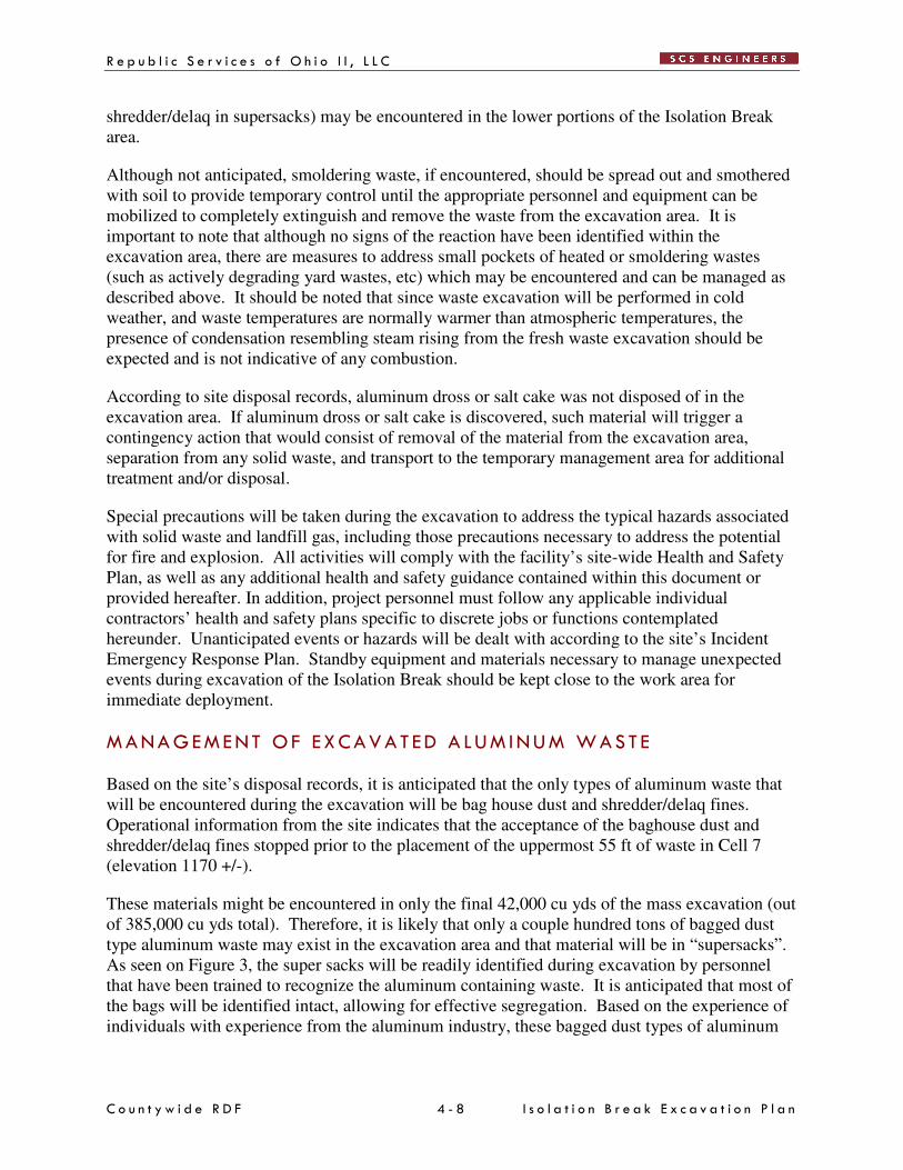
these being present in the excavation area. Some aluminum containing waste (baghouse dust and
R e p u b l i c S e r v i c e s o f O h i o I I , L L C
C o u n t y w i d e R D F 4 - 8 I s o l a t i o n B r e a k E x c a v a t i o n P l a n
shredder/delaq in supersacks) may be encountered in the lower portions of the Isolation Break
area.
Although not anticipated, smoldering waste, if encountered, should be spread out and smothered
with soil to provide temporary control until the appropriate personnel and equipment can be
mobilized to completely extinguish and remove the waste from the excavation area. It is
important to note that although no signs of the reaction have been identified within the
excavation area, there are measures to address small pockets of heated or smoldering wastes
(such as actively degrading yard wastes, etc) which may be encountered and can be managed as
described above. It should be noted that since waste excavation will be performed in cold
weather, and waste temperatures are normally warmer than atmospheric temperatures, the
presence of condensation resembling steam rising from the fresh waste excavation should be
expected and is not indicative of any combustion.
According to site disposal records, aluminum dross or salt cake was not disposed of in the
excavation area. If aluminum dross or salt cake is discovered, such material will trigger a
contingency action that would consist of removal of the material from the excavation area,
separation from any solid waste, and transport to the temporary management area for additional
treatment and/or disposal.
Special precautions will be taken during the excavation to address the typical hazards associated
with solid waste and landfill gas, including those precautions necessary to address the potential
for fire and explosion. All activities will comply with the facility’s site-wide Health and Safety
Plan, as well as any additional health and safety guidance contained within this document or
provided hereafter. In addition, project personnel must follow any applicable individual
contractors’ health and safety plans specific to discrete jobs or functions contemplated
hereunder. Unanticipated events or hazards will be dealt with according to the site’s Incident
Emergency Response Plan. Standby equipment and materials necessary to manage unexpected
events during excavation of the Isolation Break should be kept close to the work area for
immediate deployment.
M A N A G EM E N T O F EX C A V A T ED A L U M I N U M W A S T E
Based on the site’s disposal records, it is anticipated that the only types of aluminum waste that
will be encountered during the excavation will be bag house dust and shredder/delaq fines.
Operational information from the site indicates that the acceptance of the baghouse dust and
shredder/delaq fines stopped prior to the placement of the uppermost 55 ft of waste in Cell 7
(elevation 1170 +/-).
These materials might be encountered in only the final 42,000 cu yds of the mass excavation (out
of 385,000 cu yds total). Therefore, it is likely that only a couple hundred tons of bagged dust
type aluminum waste may exist in the excavation area and that material will be in “supersacks”.
As seen on Figure 3, the super sacks will be readily identified during excavation by personnel
that have been trained to recognize the aluminum containing waste. It is anticipated that most of
the bags will be identified intact, allowing for effective segregation. Based on the experience of
individuals with experience from the aluminum industry, these bagged dust types of aluminum
R e p u b l i c S e r v i c e s o f O h i o I I , L L C
C o u n t y w i d e R D F 4 - 9 I s o l a t i o n B r e a k E x c a v a t i o n P l a n
wastes pose less of a hazard than the dross type wastes. It is not expected to react quickly or
violently or generate significant amounts of heat when exposed to air or additional water.
Bag house dust or shredder/delaq fines encountered in the excavation will be separated from the
other solid waste during the excavation and loaded on separate off-road dump trucks to be hauled
to the temporary management area designated on the site and treated, if necessary, prior to
redisposal. The specific treatment methodology has not been finalized. It is anticipated that, if
necessary, the waste will be mixed with a water solution and allowed it to completely react prior
to disposal in Cell 7 and/or 8A. Laboratory analysis of a small sample of baghouse dust that has
not been landfilled, and is therefore considered to represent worst case conditions, is currently
being performed to determine the preferred method of reacting the waste to render it passive.
The laboratory analysis will provide information regarding the type and quantity of the resulting
byproducts of the treatment reaction of the aluminum waste prior to actual discovery of the super
sacks in the excavation area. Further analysis will be conducted, if necessary, as the material is
excavated from the Isolation Break. Upon completion of the treatment reaction, the material
would be disposed of at the current working face, or anywhere in the facility, without concern of
any further heat generating reactions.
M A N A G EM E N T O F I MP A C T ED S O L I D W A S TE
Solid waste that is encountered that exhibits charring or elevated temperature will be handled in
a similar fashion to the aluminum waste. Such material will be transported to an isolated area of
the temporary management area where it can be spread out, covered with soil and or with water
and allowed to cool and dry before final disposition in the redisposal area. Tarps or ADC will be
available to cover the waste to prevent saturation from a subsequent precipitation event.
I S OL A T I O N Z O N E EX C A V A T I ON
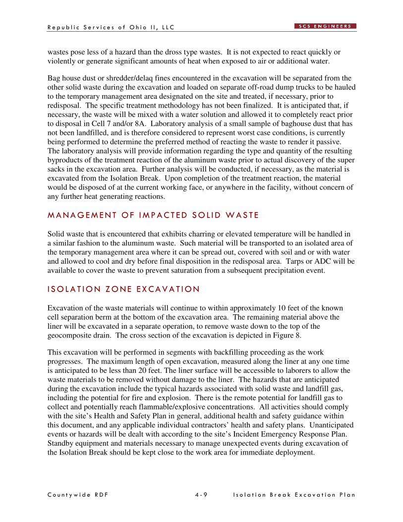
Excavation of the waste materials will continue to within approximately 10 feet of the known
cell separation berm at the bottom of the excavation area. The remaining material above the
liner will be excavated in a separate operation, to remove waste down to the top of the
geocomposite drain. The cross section of the excavation is depicted in Figure 8.
This excavation will be performed in segments with backfilling proceeding as the work
progresses. The maximum length of open excavation, measured along the liner at any one time
is anticipated to be less than 20 feet. The liner surface will be accessible to laborers to allow the
waste materials to be removed without damage to the liner. The hazards that are anticipated
during the excavation include the typical hazards associated with solid waste and landfill gas,
including the potential for fire and explosion. There is the remote potential for landfill gas to
collect and potentially reach flammable/explosive concentrations. All activities should comply
with the site’s Health and Safety Plan in general, additional health and safety guidance within
this document, and any applicable individual contractors’ health and safety plans. Unanticipated
events or hazards will be dealt with according to the site’s Incident Emergency Response Plan.
Standby equipment and materials necessary to manage unexpected events during excavation of
the Isolation Break should be kept close to the work area for immediate deployment.
R e p u b l i c S e r v i c e s o f O h i o I I , L L C
C o u n t y w i d e R D F 4 - 1 0 I s o l a t i o n B r e a k E x c a v a t i o n P l a n
I S OL A T I O N Z O N E B A C K F I L L
The isolation zone backfill will consist of soils that are Unified Soil Classification of CL. Soil
backfill will be prequalified by determining the soil classification and optimum moisture content
at the rate of one test per 1,000 cubic yards of material to be placed. The material will be free of
debris, foreign, material, and deleterious material. The material will be placed at approximately
4% above optimum moisture content in loose lifts not to exceed 18-inches and compacted with a
reasonable compactive effort in place using a small smooth drummed compactor or other
compaction equipment. No density or permeability testing will be performed on the backfill
material. Moisture content will be determined from the soil stockpile at least once per day for
each day of placement. The intent of the above requirement is to provide an impermeable barrier
to the migration of gas, liquids, and heat from Cells 5B and 5C to Cell 7. Foam, such as that
provided by Rusmar or Posi-Shell, or equal, may be applied to the excavation faces to reduce
odor emissions. See the attached Figure 5 for the excavation layout.
C OL L EC T I O N D R A I N
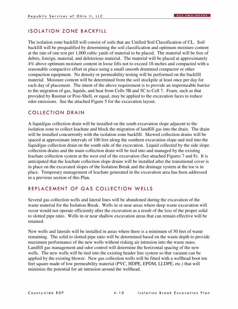
A liquid/gas collection drain will be installed on the south excavation slope adjacent to the
isolation zone to collect leachate and block the migration of landfill gas into the drain. The drain
will be installed concurrently with the isolation zone backfill. Skewed collection drains will be
spaced at approximate intervals of 100 feet along the southern excavation slope and tied into the
liquid/gas collection drain on the south side of the excavation. Liquid collected by the side slope
collection drains and the main collection drain will be tied into and managed by the existing
leachate collection system at the west end of the excavation (See attached Figures 7 and 8). It is
anticipated that the leachate collection slope drains will be installed after the transitional cover is
in place on the excavated slopes of the Isolation Break and the drainage system at the toe is in
place. Temporary management of leachate generated in the excavation area has been addressed
in a previous section of this Plan.
R EP L A C E M EN T OF GA S C O L L EC T I O N W E L L S
Several gas collection wells and lateral lines will be abandoned during the excavation of the
waste material for the Isolation Break. Wells in or near areas where deep waste excavation will
occur would not operate efficiently after the excavation as a result of the loss of the proper solid
to slotted pipe ratio. Wells in or near shallow excavation areas that can remain effective will be
retained.
New wells and laterals will be installed in areas where there is a minimum of 50 feet of waste
remaining. The solid to slotted pipe ratio will be determined based on the waste depth to provide
maximum performance of the new wells without risking air intrusion into the waste mass.
Landfill gas management and odor control will determine the horizontal spacing of the new
wells. The new wells will be tied into the existing header line system so that vacuum can be
applied by the existing blower. New gas collection wells will be fitted with a wellhead boot ten
feet square made of low permeability material (PVC, HDPE, EPDM, LLDPE, etc.) that will
minimize the potential for air intrusion around the wellhead.
R e p u b l i c S e r v i c e s o f O h i o I I , L L C
C o u n t y w i d e R D F 4 - 1 1 I s o l a t i o n B r e a k E x c a v a t i o n P l a n
Staged installation of the new wells will be necessary to provide continued management of the
landfill gas and odor issues during excavation of the waste. New wells will only be installed in
areas that have sufficient soil cover to prevent air intrusion from the sloped surfaces (See
attached drawing).
Maintenance and monitoring frequency of existing gas collection wells within 200 feet of the
excavation area will be increased to a daily regime of checking for oxygen content that could
increase as a result of air infiltration, vacuum being applied to the wells to ensure gas migration
and odors are controlled without over-pulling on the well, and methane content is being
maintained at pre-construction concentrations. Wellhead boots will be retrofitted on existing gas
collection wells within 200 feet of the edge of excavation, if monitoring shows that air is being
pulled into the landfill around the wellhead because of nearby construction activities.
Replacement or modification of gas extraction wells in the solid waste disposal area will also be
required. Gas wells in the disposal area will be extended to the new surface or replaced with a
new well. Headers and laterals will be modified or replaced to accommodate the modified or
replaced wells.
S C H ED U L E
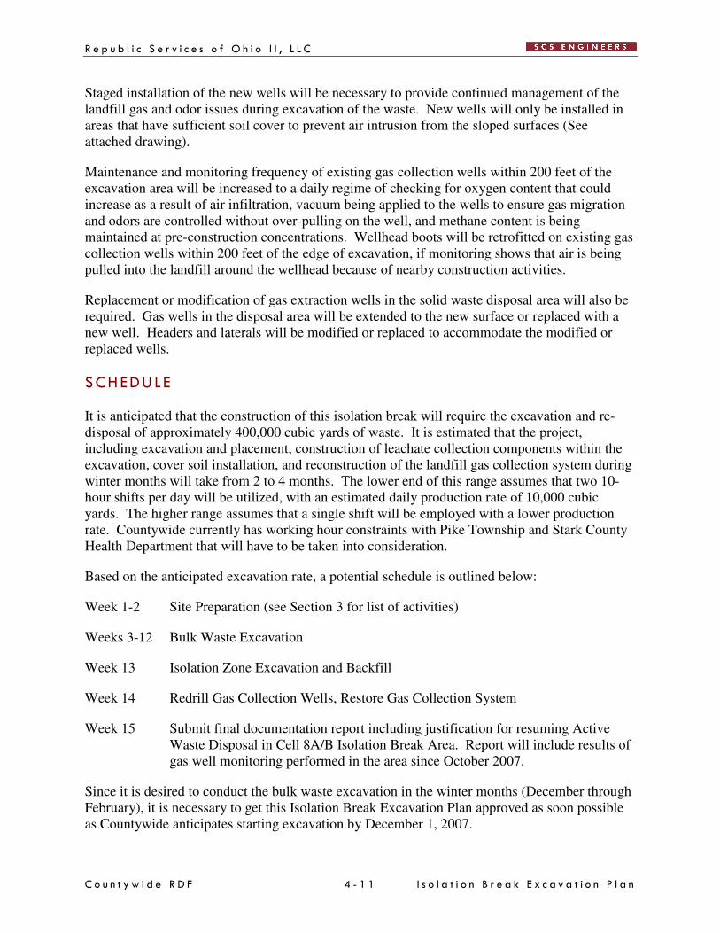
It is anticipated that the construction of this isolation break will require the excavation and re-
disposal of approximately 400,000 cubic yards of waste. It is estimated that the project,
including excavation and placement, construction of leachate collection components within the
excavation, cover soil installation, and reconstruction of the landfill gas collection system during
winter months will take from 2 to 4 months. The lower end of this range assumes that two 10-
hour shifts per day will be utilized, with an estimated daily production rate of 10,000 cubic
yards. The higher range assumes that a single shift will be employed with a lower production
rate. Countywide currently has working hour constraints with Pike Township and Stark County
Health Department that will have to be taken into consideration.
Based on the anticipated excavation rate, a potential schedule is outlined below:
Week 1-2 Site Preparation (see Section 3 for list of activities)
Weeks 3-12 Bulk Waste Excavation
Week 13 Isolation Zone Excavation and Backfill
Week 14 Redrill Gas Collection Wells, Restore Gas Collection System
Week 15 Submit final documentation report including justification for resuming Active
Waste Disposal in Cell 8A/B Isolation Break Area. Report will include results of
gas well monitoring performed in the area since October 2007.
Since it is desired to conduct the bulk waste excavation in the winter months (December through
February), it is necessary to get this Isolation Break Excavation Plan approved as soon possible
as Countywide anticipates starting excavation by December 1, 2007.
C o u n t y w i d e R D F 5 - 1 I s o l a t i o n B r e a k E x c a v a t i o n P l a n
5 STORM WATER MANAGEMENT
Storm water run-on and run-off will be managed in and adjacent to the excavation area to
minimize impact to surrounding surface waters and generation of leachate. Activities that
constitute storm water management include construction of diversion berms, construction of
diversion ditches surrounding the excavation area and on the interim slopes inside the excavation
area, and placement of daily and intermediate cover.
A combination of diversion berms and ditches will be installed around the perimeter of the
excavation to prevent surface water run-off from entering the excavation and generating
leachate. The berms and ditches will be designed to accommodate a 25-year/24-hour storm
event. Erosion control structures and sedimentation control structures will be constructed if
needed to comply with the facility authorizing document. Earthwork for the storm water
management system will be seeded and mulched (weather permitting) or covered with erosion
mats to minimize erosion and scouring. The location of the proposed final diversion ditches and
let down pipe structures are shown on Figures 5 through 8.
Diversion berms will also be constructed along the excavation slopes atop the daily soil cover to
minimize the generation of leachate to be managed by the liquid/gas collection trench. These
diversion berms will be tied into the storm water management system for the facility where
possible. Erosion controls will be installed where necessary to minimize the impact to the
sedimentation control structures on the site.
Erosion controls will consist of geotextile silt fences, straw bale erosion control dikes placed in
the ditches, seeding and mulching of all disturbed areas (as weather permits), and rock channel
protection where necessary.
C o u n t y w i d e R D F 6 - 1 I s o l a t i o n B r e a k E x c a v a t i o n P l a n
6 ODOR CONTROL MEASURES
C U R R E N T OD OR C ON TR OL P R OC ED U R ES
On June 28, 2007, Countywide submitted a revised Odor Control Plan. This Plan has not yet
been approved, but most measures contained in the Plan (odor mitigation and odor
neutralization) are currently implemented and will be continued throughout the excavation
process.
W A S T E EX C A V A T I ON I S S U ES
Excavation of the waste to provide the Isolation Break may result in the release of odors now
being contained by the landfill cover system, the gas control system, and the odor neutralization
system. The existing control systems have been successfully controlling the migration of odors
to off-site receptors. The use of these existing systems will be continued during the excavation
of the Isolation Break. In addition, portable odor control systems will be used as necessary,
weather permitting. Modifications to the gas control system and the odor neutralization system
will be necessary in the area of the waste excavation. The Odor Control Plan procedures
currently being executed will continue during the excavation of the Isolation Break.
Supplemental odor control measures will be used, if the adjustments to the gas control system
and the odor neutralizing system are not adequate to control the odor emanating from the waste
excavation. Supplemental measures are addressed in the section below.
P R OP OS ED OD OR C ON TR OL MEA S U R ES
The measures described in the Odor Control Plan, revised June 2007 will be continued during the
excavation of the waste for the Isolation Break. Additional odor control measures will be
implemented as described in the following paragraphs.
Wa s t e C o v e r
Freshly exposed waste will be covered as soon as practical. With the exception of the active
excavation area, areas that are stripped of cover soil will be re-covered with daily cover soil or
alternate daily cover (ADC) to promote good odor control and minimize the generation of
leachate from rainfall events.
Cover will be provided by spreading a minimum 6-inch lift of soil, spraying a non-combustible
foam material, or spraying other alternate daily cover material, possibly containing odor control
products, directly on the exposed waste. The cover will enhance storm water management and
prevent blowing litter. Foam or alternate daily cover material will be used on steep temporary
faces that will be generated during the excavation process. Foam may also be applied in the
trench excavations. Foam will consist of materials similar or equal to that provided by Rusmar
or Posi-Shell. Foams or alternate daily cover material will not be used in areas of high traffic.
C o u n t y w i d e R D F 6 - 2 I s o l a t i o n B r e a k E x c a v a t i o n P l a n
L a n d f i l l G a s C o n t r o l S y s t em
Existing landfill gas collection wells will be abandoned in the Isolation Break excavation area
where cuts are over ten feet in depth. Wells in areas where the excavation depth is less than ten
feet will be maintained throughout the Isolation Break excavation procedures.
New wells will be likely be added in areas where existing wells are not within one hundred feet
and waste depth is a minimum of 50 feet, after the Isolation Break slopes have been excavated.
New well placement will be somewhat dependent on the depth of waste remaining, the
horizontal distance to the new waste slope in the Isolation Break, and the anticipated radius of
influence of the existing wells and the proposed well. New wells will be spaced to provide the
same or better coverage than is being provided by the existing system. Subsurface drainage
system components will be tied to the landfill gas collection system and vacuum applied to
prevent odor emissions from the piping systems.
Odo r N e u t r a l i z a t i o n S y s t em
Countywide installed an initial odor neutralizing system in 2004. This system consisted of
approximately 1500 linear feet of pole mounted spray system on the west berm of the landfill.
In 2006, Countywide greatly expanded the size of this system to assist in controlling odors as
classified previously. As of January 2007, this system was expanded to nearly 6000 linear feet of
neutralizer system. The system is split to two separate areas 1) the expanded west berm and 2)
through the middle of 88 acre landfill footprint.
These two systems essentially surround the reaction zone identified during 2006 so that odors
that emanate from this zone may be neutralized by these systems.
Existing permanent or portable odor neutralizing systems will be utilized as necessary and as
temperatures permit to minimize odors associated with the excavation. It is likely that an
extension to, or temporary relocation of, the neutralizing system, with permanent components or
temporary portable equipment, will be necessary adjacent to the working face of the excavation
to minimize odors. The extent of the neutralizing system modifications will be based on the
placement of new landfill gas control wells and the effectiveness of the existing system to
suppress the odor from the newly excavated area. Portable odor control systems will be used as
necessary within the excavation area or disposal area
The Nasal Ranger monitoring program utilized by Countywide has proven to be a useful,
reliable, and objective program for determining relative odor strength since first being used at
Countywide in September, 2006. Countywide will continue the use of this program throughout
the project.
It is also likely that odor control will be required where the waste is being temporarily stored and
permanently disposed in Cells 7 and/or 8A. Odor control in these areas will likely be provided
by direct spraying of odor neutralizer with portable equipment.
C o u n t y w i d e R D F 7 - 1 I s o l a t i o n B r e a k E x c a v a t i o n P l a n
7 PERFORMANCE MONITOR ING
Visual observation of the excavation should confirm whether or not the excavation area has been
heat-affected or otherwise physically impacted by the reaction. During construction of the
Isolation Break, Countywide will employ a third-party monitor to provide full-time observation
of the excavation process. We also expect that the OEPA will provide full-time personnel to
monitor the excavation. The third-party monitor and the OEPA personnel will provide redundant
observation and will inform each other of their observations on an ongoing basis. This vital
process will ensure that both parties concur that the reaction has not moved into, or through the
excavation area. If there are differences of opinion, those specific instances will be mutually
noted.
During the completion of the Isolation Break construction, a monitoring program, including field
measurements of landfill gas temperature, and laboratory analysis of landfill gas samples, will be
conducted in Cell 7 to document that the waste in Cell 7 is not undergoing a non-typical,
combustion-type reaction in the solid waste. The Findings & Orders performance criteria for
determining when the “fire” is out and the Ohio EPA landfill fire guidance will be used to
evaluate the conditions in Cell 7. The performance criteria include carbon monoxide, hydrogen,
and methane concentrations in landfill gas at the wellhead; and wellhead landfill gas
temperature. The relevant F&O criteria area:
Carbon Monoxide Concentrations below 100 ppm
Hydrogen Concentrations below 5 percent by volume
Methane Concentrations indicative of methanogenesis
Wellhead Gas
Temperature
Consistently below 131 degrees F and not exceeding
150 degrees F
The landfill fire guidance criteria can also be used to evaluate Cell 7. These criteria are 140
degrees F for wellhead gas temperature, 170 degrees F for in-situ waste temperatures, and 100 to
1,000 ppm carbon monoxide.
Because waste from the excavation will be placed on Cells 7 and 8A (north of the excavation),
and because the waste in Cells 7 and 8A is relatively new, we are specifically eliminating
settlement observation from the criteria that will be used to evaluate the presence or absence of
reaction in Cell 7 and 8A. We believe that non-uniform settlement will occur in those areas due
to normal waste consolidation and degradation processes.
The monitoring program will commence immediately. Assuming that the excavation occurs in
December 2007 and January and February 2008, there will be five months of gas well
observations in Cell 7. We propose that the following wells be monitored for the determination:
PW-304, 312, 313, 329, 330, and 331. In addition, the selected wells which are located in Cell
7, but are within the “:footprint” of the excavation (PW-314, 325, 326, and 328) will be
monitored in the same manner until they must be removed due to the excavation. We are
specifically excluding new wells in the excavated area (see Figure 10) from the monitoring as
they may take a couple months to tune and stabilize to produce consistent gas quality.
C o u n t y w i d e R D F 7 - 2 I s o l a t i o n B r e a k E x c a v a t i o n P l a n
Landfill gas samples will be collected from the gas extraction wells on a monthly basis. The
samples will be analyzed for hydrogen, methane, and carbon monoxide using the ASTM D-1946
method. The results will be included in the on-line Locus database. The landfill gas extraction
wells will be monitored for temperature weekly using the GEM meter or thermometer,
depending on the temperature range. In addition, weekly downhole temperature measurements
will be performed. The temperature data will also be incorporated in the Locus database.
The results from October, November, and December 2007, and January and February 2008
should allow determination of whether or not the reaction has progressed into Cell 7. At that
point, Countywide will submit documentation requesting immediate approval to fill the isolation
break that exists between Cells 8A and 8B.

C o u n t y w i d e R D F I s o l a t i o n B r e a k E x c a v a t i o n P l a n
F i g u r e s
C o u n t y w i d e R D F A - 1 I s o l a t i o n B r e a k E x c a v a t i o n P l a n
App e n d i x A
B o r i n g L o g s
C o u n t y w i d e R D F B - 1 I s o l a t i o n B r e a k E x c a v a t i o n P l a n
App e n d i x B
S t a b i l i t y A n a l y s i s
C o u n t y w i d e R D F C - 1 I s o l a t i o n B r e a k E x c a v a t i o n P l a n
App e n d i x C
A DC P r o d u c t I n f o rm a t i o n