Embed Size (px)
Citation preview

A series of acoustic measurementsmade on brick walls has allowed forthe obtainment of results on the soundreduction index of various types ofwalls and for the perfection of asimplified estimation model of the in-situ acoustic insulation.
The Prime Minister’s Decree dated 5thDecember 1997 requires that the acousticperformance of buildings be verified withreference to the state of the actualconstruction [1].The construction performance of a buildingcomponent is nearly always inferior to thecertified laboratory result, be it in terms ofthe different construction conditions, be itbecause of the presence of different soundtransmission paths that involve the flankingstructures of any two rooms.This flanking transmission assumes adifferent importance according to the typeof building components and structuraljoints used between any two rooms, withthe former generally varying from between1 to over 5 decibels of sound transmissioncontribution. The knowledge of the exactcontribution is what is more, of primaryimportance for the design of the building.The assessment of the constructionperformance of the building components ispossible thanks to the statistic calculationmodels that call for the exact knowledge ofthe acoustic properties of all thecomponents affected by the transmission.One of these calculation methods inparticular is the object of an internationalstandard [2], a method that has even beendealt with in the guidelines defined by theItalian Standardisation Institute UNI’sWorking Group 12 [3].In order to apply this method, which allowsthe laboratory value to be converted into aconstruction value, it is necessary to knowthe level of vibration transmission thattakes place in correspondence with thestructure’s partition joints and the soundreduction index of all the componentsaffected by the transmission. The firstvalue comes from the measurements madein special laboratories, for which aninternational standard is currently beingdefined [4]. The second value is, on theother hand, deduced from normallaboratory measurements, already made onbrick walls by various research institutes,for which, however, a systematic campaignaccording to the latest standard provisionsis still lacking [5].In this context, ANDIL (the Italian BrickIndustry Association) that in the past hasalready carried out experimental researchin collaboration with the Universities ofParma, Ferrara and Bologna [6, 7, 8, 9, 10,11], has promoted a research project withthe Universities of Ferrara, Trent andPadua, with the following main objectives:• laboratory verification of the airborne
sound insulation performance of alimited number of internal vertical brickwalls of varying types;
• the verification of an estimation methodfor the acoustic performance of a
1
L’industriadeiLaterizi
novembre dicembre2001.72
di/by R. Albatici, A. Di Bella, P. Fausti, A. Frattari, G.Nicosia, R. Pompoli, S. Secchi, M. Tosi, R. Zecchin
Isolamento acustico di pareti interne in laterizio: misuresperimentali e metodi di previsione
ACOUSTIC INSULATIONOF INTERNAL BRICKWALLS: TESTMEASUREMENTS ANDPREDICTION METHODS
Una campagna di misure acustiche su pareti in laterizio hapermesso di documentare il potere fonoisolante di diversetipologie e di mettere a punto un modello di previsionesemplificato dell’isolamento acustico in opera.
Il D.P.C.M. del 5 dicembre 1997 richiede la verifica delleprestazioni acustiche degli edifici con riferimento alla situazione direale messa in opera [1].La prestazione in opera di un componente edilizio è quasi sempreinferiore a quella certificata in laboratorio, sia per le diverse condizionidi realizzazione, sia per la presenza di percorsi di trasmissione sonorache coinvolgono le strutture laterali dei due ambienti.Tale trasmissione laterale assume un’entità differenziata a secondadella tipologia dei componenti e dei giunti strutturali tra questi,variando in genere tra 1 ed oltre 5 decibel di contributopeggiorativo. La conoscenza esatta di tale contributo è peraltro diprimaria importanza per la fase di progettazione.La valutazione delle prestazioni in opera dei componenti edilizi è possibilegrazie a modelli di calcolo statistici che richiedono la conoscenza esattadelle proprietà acustiche di tutti i componenti coinvolti dallatrasmissione. Tra questi metodi di calcolo, uno in particolare è oggetto diuna norma internazionale [2], metodo che è ripreso anche dalle lineeguida definite dal Gruppo di Lavoro 12 dell’UNI [3].Per l’applicazione del metodo, che permette di convertire il valoredi laboratorio nel relativo valore in opera, è necessario conoscerel’entità della trasmissione delle vibrazioni che avviene incorrispondenza dei giunti laterali della struttura divisoria e leprestazioni di potere fonoisolante di tutti i componenti coinvoltidalla trasmissione. Il primo dato viene ricavato con misureeffettuate in laboratori speciali, per i quali è in fase di definizioneuna norma internazionale [4]. Il secondo dato viene invece dedottoda normali misure di laboratorio, già effettuate su pareti in laterizioda diversi istituti di ricerca, ma di cui manca ancora una campagnasistematica secondo le più recenti disposizioni normative [5].In questo panorama, l’ANDIL (Associazione Nazionale DegliIndustriali dei Laterizi), che già in passato ha svolto attività diricerca sperimentali in collaborazione con l’Università di Parma,Ferrara e Bologna [6,7,8,9,10,11], ha promosso un progetto diricerca con l’Università di Ferrara, Trento e Padova con i seguentiobiettivi principali:• verifica in laboratorio delle prestazioni acustiche di isolamento al
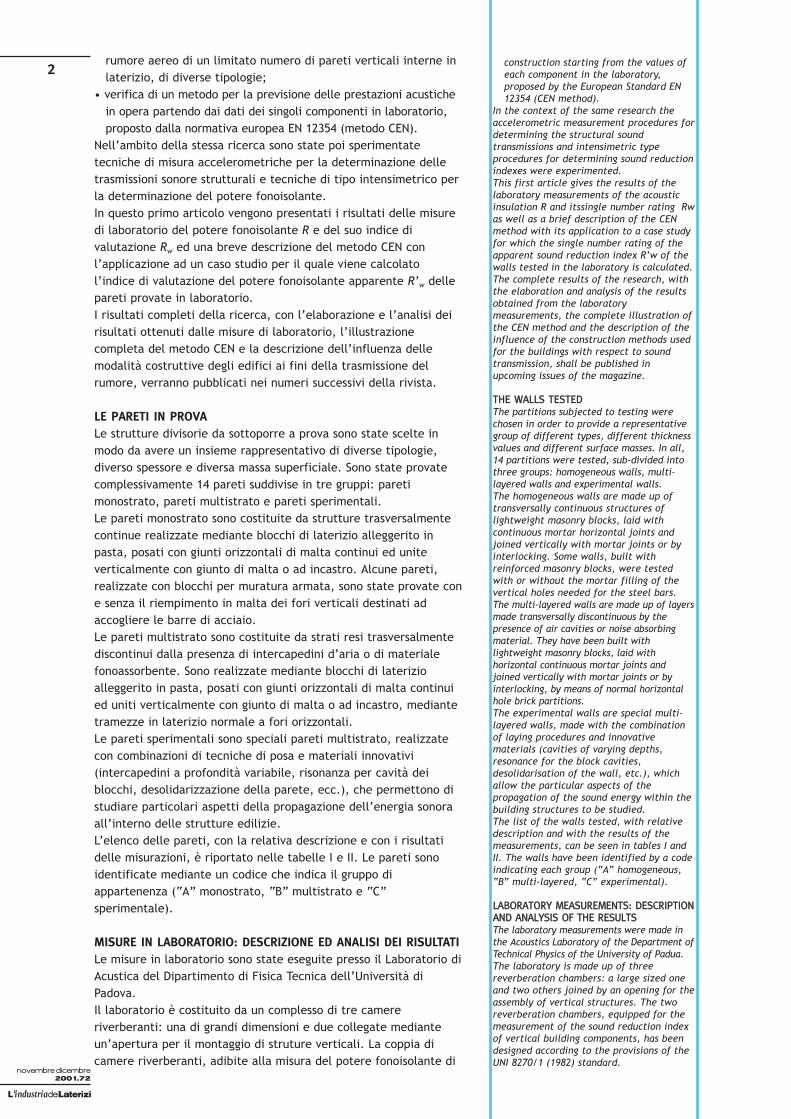
rumore aereo di un limitato numero di pareti verticali interne inlaterizio, di diverse tipologie;
• verifica di un metodo per la previsione delle prestazioni acustichein opera partendo dai dati dei singoli componenti in laboratorio,proposto dalla normativa europea EN 12354 (metodo CEN).
Nell’ambito della stessa ricerca sono state poi sperimentatetecniche di misura accelerometriche per la determinazione delletrasmissioni sonore strutturali e tecniche di tipo intensimetrico perla determinazione del potere fonoisolante. In questo primo articolo vengono presentati i risultati delle misuredi laboratorio del potere fonoisolante R e del suo indice divalutazione Rw ed una breve descrizione del metodo CEN conl’applicazione ad un caso studio per il quale viene calcolatol’indice di valutazione del potere fonoisolante apparente R’w dellepareti provate in laboratorio.I risultati completi della ricerca, con l’elaborazione e l’analisi deirisultati ottenuti dalle misure di laboratorio, l’illustrazionecompleta del metodo CEN e la descrizione dell’influenza dellemodalità costruttive degli edifici ai fini della trasmissione delrumore, verranno pubblicati nei numeri successivi della rivista.
LE PARETI IN PROVALe strutture divisorie da sottoporre a prova sono state scelte inmodo da avere un insieme rappresentativo di diverse tipologie,diverso spessore e diversa massa superficiale. Sono state provatecomplessivamente 14 pareti suddivise in tre gruppi: paretimonostrato, pareti multistrato e pareti sperimentali.Le pareti monostrato sono costituite da strutture trasversalmentecontinue realizzate mediante blocchi di laterizio alleggerito inpasta, posati con giunti orizzontali di malta continui ed uniteverticalmente con giunto di malta o ad incastro. Alcune pareti,realizzate con blocchi per muratura armata, sono state provate cone senza il riempimento in malta dei fori verticali destinati adaccogliere le barre di acciaio.Le pareti multistrato sono costituite da strati resi trasversalmentediscontinui dalla presenza di intercapedini d’aria o di materialefonoassorbente. Sono realizzate mediante blocchi di laterizioalleggerito in pasta, posati con giunti orizzontali di malta continuied uniti verticalmente con giunto di malta o ad incastro, mediantetramezze in laterizio normale a fori orizzontali.Le pareti sperimentali sono speciali pareti multistrato, realizzatecon combinazioni di tecniche di posa e materiali innovativi(intercapedini a profondità variabile, risonanza per cavità deiblocchi, desolidarizzazione della parete, ecc.), che permettono distudiare particolari aspetti della propagazione dell’energia sonoraall’interno delle strutture edilizie.L’elenco delle pareti, con la relativa descrizione e con i risultatidelle misurazioni, è riportato nelle tabelle I e II. Le pareti sonoidentificate mediante un codice che indica il gruppo diappartenenza (“A” monostrato, “B” multistrato e “C”sperimentale).
MISURE IN LABORATORIO: DESCRIZIONE ED ANALISI DEI RISULTATI Le misure in laboratorio sono state eseguite presso il Laboratorio diAcustica del Dipartimento di Fisica Tecnica dell’Università diPadova.Il laboratorio è costituito da un complesso di tre camereriverberanti: una di grandi dimensioni e due collegate medianteun’apertura per il montaggio di struture verticali. La coppia dicamere riverberanti, adibite alla misura del potere fonoisolante di
construction starting from the values ofeach component in the laboratory,proposed by the European Standard EN12354 (CEN method).
In the context of the same research theaccelerometric measurement procedures fordetermining the structural soundtransmissions and intensimetric typeprocedures for determining sound reductionindexes were experimented.This first article gives the results of thelaboratory measurements of the acousticinsulation R and itssingle number rating Rwas well as a brief description of the CENmethod with its application to a case studyfor which the single number rating of theapparent sound reduction index R’w of thewalls tested in the laboratory is calculated.The complete results of the research, withthe elaboration and analysis of the resultsobtained from the laboratorymeasurements, the complete illustration ofthe CEN method and the description of theinfluence of the construction methods usedfor the buildings with respect to soundtransmission, shall be published inupcoming issues of the magazine.
TTHHEE WWAALLLLSS TTEESSTTEEDDThe partitions subjected to testing werechosen in order to provide a representativegroup of different types, different thicknessvalues and different surface masses. In all,14 partitions were tested, sub-divided intothree groups: homogeneous walls, multi-layered walls and experimental walls.The homogeneous walls are made up oftransversally continuous structures oflightweight masonry blocks, laid withcontinuous mortar horizontal joints andjoined vertically with mortar joints or byinterlocking. Some walls, built withreinforced masonry blocks, were testedwith or without the mortar filling of thevertical holes needed for the steel bars. The multi-layered walls are made up of layersmade transversally discontinuous by thepresence of air cavities or noise absorbingmaterial. They have been built withlightweight masonry blocks, laid withhorizontal continuous mortar joints andjoined vertically with mortar joints or byinterlocking, by means of normal horizontalhole brick partitions.The experimental walls are special multi-layered walls, made with the combinationof laying procedures and innovativematerials (cavities of varying depths,resonance for the block cavities,desolidarisation of the wall, etc.), whichallow the particular aspects of thepropagation of the sound energy within thebuilding structures to be studied.The list of the walls tested, with relativedescription and with the results of themeasurements, can be seen in tables I andII. The walls have been identified by a codeindicating each group (“A” homogeneous,“B” multi-layered, “C” experimental).
LLAABBOORRAATTOORRYY MMEEAASSUURREEMMEENNTTSS:: DDEESSCCRRIIPPTTIIOONNAANNDD AANNAALLYYSSIISS OOFF TTHHEE RREESSUULLTTSSThe laboratory measurements were made inthe Acoustics Laboratory of the Department ofTechnical Physics of the University of Padua.The laboratory is made up of threereverberation chambers: a large sized oneand two others joined by an opening for theassembly of vertical structures. The tworeverberation chambers, equipped for themeasurement of the sound reduction indexof vertical building components, has beendesigned according to the provisions of theUNI 8270/1 (1982) standard.
2
L’industriadeiLaterizi
novembre dicembre2001.72

3componenti verticali di edificio, è stata progettata tenendo contodelle prescrizioni della norma UNI 8270/1 (1982).Dai risultati ottenuti si può osservare che molte delle tipologie dipareti provate hanno fornito valori dell’indice di valutazione delpotere fonoisolante superiori a 50 dB. In particolare, si può osservare che alle medie frequenze (200-500 Hz), per quasi tutte le pareti testate, i valori del poterefonoisolante (R) si discostano molto dalla curva di riferimentoutilizzata per il calcolo dell’indice di valutazione (Rw) penalizzandomolto il risultato. I buoni risultati che si ottengono invece allebasse frequenze, benchè siano molto importanti per la qualitàdell’isolamento acustico, influiscono poco sul calcolo dell’indice divalutazione. Per le singole pareti si possono fare le seguenti considerazioni:• le pareti A07, A08 e A09, realizzate con blocchi semipieni ad
incastro, senza la malta nei giunti verticali, hanno fornito risultatileggermente al di sotto delle aspettative in relazione alla loromassa superficiale; questo può essere giustificato dal mancatoriempimento dei giunti verticali che ha determinato dei percorsisonori preferenziali interrotti soltanto dall’intonaco sui due lati;
• la parete sperimentale C02, ottenuta con un tavolato in tramezzeda 8 cm, una intercapedine di 2 cm con fibra di poliesterecompressa e un tavolato in tavelle da 6 cm, ha fornito rispostemolto interessanti in relazione alla massa superficiale; questosignifica che buoni risultati si possono ottenere con pareti doppieseparate da materiali resilienti anche senza l’intercapedine;
• il confronto tra le pareti doppie sperimentali C03 (blocchi a Tcon tagli verticali effettuati allo scopo di creare delle cavitàrisonanti fonoassorbenti) e C04 (blocchi a T senza tagli) hamostrato che il vantaggio ottenibile dall’assorbimento vieneperso completamente dall’indebolimento della struttura: i tagliverticali riducono in effetti lo spessore utile del blocco.
METODO SEMPLIFICATO DI PREVISIONE DEL POTEREFONOISOLANTE APPARENTEIl potere fonoisolante apparente R’ esprime la quantità di energiasonora trasmessa da una partizione nelle sue reali condizioni diutilizzo. Tale quantità differisce dal potere fonoisolante R,risultante da misure di laboratorio o da calcolo teorico, in quantotiene conto, oltre che della trasmissione diretta della parete,anche di eventuali percorsi di trasmissione aerea del suono e deipercorsi di trasmissione strutturale dovuti ai componenti laterali.La nuova norma europea EN 12354-1 [2,3] indica un metodo dicalcolo basato su alcune ipotesi semplificative che permette distimare il potere fonoisolante apparente di una partizione a partiredai valori del potere fonoisolante relativi ai diversi percorsi ditrasmissione strutturale.
(1)
dove RDd e Rij sono rispettivamente i valori in funzione dellafrequenza del potere fonoisolante per trasmissione diretta(attraverso la parete di separazione dei due ambienti) e del poterefonoisolante per trasmissione laterale (attraverso il genericopercorso i-j).In questa formulazione viene trascurato il contributo dellatrasmissione aerea tra condotti, prese d’aria ed altri elementi.Per ogni giunto tra parete di separazione e strutture laterali (paretie solai), si individuano tre percorsi di trasmissione laterale ij,
′R = −10 lg 10RDd
10+ 10
Rij
10∑
dB( )
The results show that many of the wall typestested have acoustic insulation indexassessment values of over 50dB.In particular, it may be observed that at themedium frequencies (200-500 Hz), for nearlyall the tested walls, the sound reductionindexes (R) shift greatly from the referencecurve used for the calculation of thesinglenumber rating (Rw), thus greatly penalisingthe result. On the other hand, even if veryimportant for the quality of the acousticinsulation, the good results obtained at thelower frequencies have little influence onthe calculation of thesingle number rating .For the individual walls the followingconsiderations may be made:• the walls A07, A08 and A09, made with
interlocking perforated blocks, withoutmortar in the vertical joints have givenresults that fall slightly below theexpectations in relation to their surfacemass; this may be justified by the factthat the vertical joints were not filledthus determining the preferential soundpaths being interrupted only by theplaster on the two sides;
• the experimental wall C02, obtained withan 8 cm partition layer, a 2 cm cavity withcompressed polyester and a 6 cm slablayer, gave very interesting outcomes inrelation to the surface mass; this meansthat positive results may be obtained withdouble walls separated by resilientmaterials even without the need for acavity;
• the comparison between the doubleexperimental walls C03 (T shaped blockswith vertical cuts made to create resonantnoise absorbing cavities) and C04 (Tshaped blocks without cuts) has shownthat the advantage obtained by theabsorption is totally lost by the weakeningof the structure: the vertical cuts in factreduce the working thickness of the block.
AA SSIIMMPPLLIIFFIIEEDD MMEETTHHOODD FFOORR EESSTTIIMMAATTIINNGGTTHHEE AAPPPPAARREENNTT SSOOUUNNDD RREEDDUUCCTTIIOONN IINNDDEEXXThe apparent sound reduction index R’expresses the quantity of sound energytransmitted by a wall under its realconditions of use. This quantity differsfrom the sound reduction index R’,resulting from the laboratorymeasurements or from the theoreticalcalculation, in that it takes intoconsideration, in addition to the directtransmission of the wall, even any eventualairborne sound transmission paths and thestructural transmission paths given by theflanking components. The new Europeanstandard EN 12354-1 [2, 3] shows acalculation method based upon severalsimplifying hypotheses which allows for theapparent sound reduction index of apartition to be estimated starting from thesound reduction index relative to thedifferent structural transmission paths.
(1)
where RDd and Rij are respectively thevalues, as a function of the frequency, of thesound reduction index for direct transmission(through the dividing wall of the two rooms)and the sound reduction index for flankingtransmission (through the generic path i-j).This formula ignores the contribution of theairborne transmission through pipes, air ventsand other elements. For every joint betweenthe dividing partitions and the flankingstructures (walls and ceilings), there arethree flanking transmission paths ij, generallyshown with the letters Df, Ff, Fd (D stands for
′R = −10 lg 10
RDd
10+ 10
Rij
10∑
dB( )
L’industriadeiLaterizi
novembre dicembre2001.72
4
L’industriadeiLaterizi
novembre dicembre2001.72
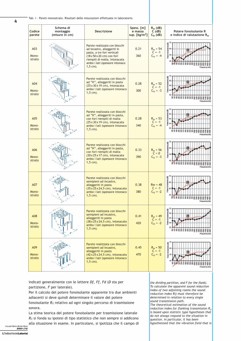
Schema di Spess. [m] Rw (dB)Codice montaggio Descrizione e massa C (dB) Potere fonoisolante Rparete (misure in cm) sup. [kg/m2] Ctr (dB) e indice di valutazione Rw
A03 0.21 Rw = 54C = -1
Mono- 360 Ctr = -4strato
A04 0.28 Rw = 52C = -1
Mono- 300 Ctr = -3strato
A05 0.28 Rw = 53C = -1
Mono- 340 Ctr = -4strato
A06 0.33 Rw = 56C = 0
Mono- 390 Ctr = -3strato
A07 0.38 Rw = 48C = -1
Mono- 380 Ctr = -2strato
A08 0.41 Rw = 49C = -1
Mono- 420 Ctr = -2strato
A09 0.45 Rw = 50C = -1
Mono- 470 Ctr = -2strato
Parete realizzata con blocchiad incastro, alleggeriti inpasta, a tre fori verticali(18x50x20 cm) con foririempiti di malta, intonacataambo i lati (spessore intonaco1,5 cm).
Parete realizzata con blocchiad “H”, alleggeriti in pasta(25 x 30 x 19 cm), intonacataambo i lati (spessore intonaco1,5 cm).
Parete realizzata con blocchiad “H”, alleggeriti in pasta,con fori riempiti di malta(25 x 30 x 19 cm), intonacataambo i lati (spessore intonaco1,5 cm).
Parete realizzata con blocchiad “H”, alleggeriti in pasta,con fori riempiti di malta(30 x 25 x 17 cm), intonacataambo i lati (spessore intonaco1,5 cm).
Parete realizzata con blocchisemipieni ad incastro,alleggeriti in pasta(35 x 25 x 24,5 cm), intonacataambo i lati (spessore intonaco1,5 cm).
Parete realizzata con blocchisemipieni ad incastro,alleggeriti in pasta(38 x 25 x 24,5 cm), intonacataambo i lati (spessore intonaco1,5 cm).
Parete realizzata con blocchisemipieni ad incastro,alleggeriti in pasta(42 x 25 x 24,5 cm), intonacataambo i lati (spessore intonaco1,5 cm).
Tab. I - Pareti monostrato. Risultati delle misurazioni effettuate in laboratorio.
indicati generalmente con le lettere Df, Ff, Fd (D sta perpartizione, F per laterale).Per il calcolo del potere fonoisolante apparente tra due ambientiadiacenti si deve quindi determinare il valore del poterefonoisolante Rij relativo ad ogni singolo percorso di trasmissionesonora.La stima teorica del potere fonoisolante per trasmissione lateraleRij si fonda su ipotesi di tipo statistico che non sempre si addiconoalla situazione in esame. In particolare, si ipotizza che il campo di
the dividing partition, and F for the flank).To calculate the apparent sound reductionindex of two adjoining rooms the soundreduction index Rij must therefore bedetermined in relation to every singlesound transmission path.The theoretical estimation of the soundreduction index for flanking transmission Rijis based upon statistic type hypotheses thatdo not always respond to the situation inquestion. In particular, it has beenhypothesised that the vibration field that is

5
vibrazioni che si stabilisce nella partizione e nelle strutture lateralidei due ambienti esaminati, come conseguenza della pressionesonora presente in essi, sia il più possibile uniforme. Questa ipotesipone evidenti problemi di validità del modello di calcolo inpresenza di discontinuità strutturali rappresentate da telai incemento armato o in acciaio.Per questo tipo di soluzioni, il metodo di calcolo presentato ha unminor grado di affidabilità, anche se può essere ancora utilizzatoper ottenere una prima stima del potere fonoisolante apparente. A
L’industriadeiLaterizi
novembre dicembre2001.72
Wall Assembly Description Thickness [m] Rw (dB) Acoustic insulation potential Code diagram (in cm.) and surface C (dB) R and assessment
mass [kg/m2] Ctr (dB) index Rw
A03 0.21 Rw = 54C = -1
Homo- 360 Ctr = -4geneous
A04 0.28 Rw = 52C = -1
Homo- 300 Ctr = -3geneous
A05 0.28 Rw = 53C = -1
Homo- 340 Ctr = -4geneous
A06 0.33 Rw = 56C = 0
Homo- 390 Ctr = -3geneous
A07 0.38 Rw = 48C = -1
Homo- 380 Ctr = -2geneous
A08 0.41 Rw = 49C = -1
Homo- 420 Ctr = -2geneous
A09 0.45 Rw = 50C = -1
Homo- 470 Ctr = -2geneous
Wall built with interlockingblocks, made with a lightenedmixture, with three verticalholes (18x50x20 cm) withmortar filled holes, plasteredon both sides (plasterthickness 1.5 cm).
Wall built with “H” shapedblocks, made with alightened mixture(25 x 30 x 19 cm), plasteredon both sides (plasterthickness 1.5 cm).
Wall built with “H” shapedblocks, made with alightened mixture, withmortar filled holes(25 x 30 x 19 cm), plasteredon both sides (plasterthickness 1.5 cm).
Wall built with “H” shapedblocks, made with alightened mixture, withmortar filled holes(30 x 25 x 17 cm), plasteredon both sides (plasterthickness 1.5 cm).
Wall built with perforatedinterlocking blocks, madewith a lightened mixture(35 x 25 x 24.5 cm), plasteredon both sides (plasterthickness 1.5 cm).
Wall built with perforatedinterlocking blocks, madewith a lightened mixture(38 x 25 x 24.5 cm), plasteredon both sides (plasterthickness 1.5 cm).
Wall built with perforatedinterlocking blocks, madewith a lightened mixture(42 x 25 x 24.5 cm), plasteredon both sides (plasterthickness 1.5 cm).
Tab. I - Homogeneous walls. The results of the measurements carried out in a labora-tory context.
formed in the dividing partition and in theflanking structures of the two rooms inquestion, as a result of the sound pressurepresent in them, should be as uniform aspossible. This hypothesis highlights theproblems of the validity of the calculationmodel in the presence of structuraldiscontinuities represented by reinforcedconcrete or steel framework.For this type of solution, the calculationmethod presented has a lower rate ofreliability, even if it may still be used to

6
L’industriadeiLaterizi
novembre dicembre2001.72
Schema di Spess. [m] Rw (dB)Codice montaggio Descrizione e massa C (dB) Potere fonoisolante Rparete (misure in cm) sup. [kg/m2] Ctr (dB) e indice di valutazione Rw
B01 0.29 Rw = 50C = -1
Multi- 190 Ctr = -4strato
B02 0.29 Rw = 53C = 0
Multi- 300 Ctr = -3strato
B03 0.31 Rw = 53C = 0
Multi- 260 Ctr = -4strato
B04 0.33 Rw = 49C = -1
Multi- 250 Ctr = -5strato
C02 0.19 Rw = 46C = -1
Speri- 160 Ctr = -5mentale
C03 0.31 Rw = 52C = -1
Speri- 320 Ctr = -4mentale
C04 0.31 Rw = 54C = -1
Speri- 320 Ctr = -4mentale
Parete realizzata con tavolato intramezze normali a 10 fori(8x25x25 cm) ed intonaco(1,5 cm) lato esterno; intercape-dine di 10 cm con lana di rocciada 5 cm (50 kg/m3) appoggiata altavolato; tavolato in tramezzenormali a 10 fori (8x25x25 cm)ed intonaco sul lato esterno.
Parete realizzata con tavolato intramezze normali a 15 fori(12x25x25 cm) ed intonaco (1,5cm) lato esterno; intercapedine di 6cm con lana di roccia da 5 cm (den-sità 50 kg/m3); tavolato in tra-mezze semipiene ad incastro, alleg-gerite in pasta (8x50x24,5 cm) edintonaco (1,5 cm) lato esterno.
Parete realizzata con tavolato intramezze normali a 10 fori(8x25x25 cm) ed intonaco(1,5 cm) lato esterno; intercape-dine di 12 cm; tavolato in tra-mezze semipiene ad incastro, al-leggerite in pasta(8x50x24,5 cm) ed intonaco(1,5 cm) lato esterno.
Parete realizzata con tavolato intramezze normali a 15 fori(12x25x25 cm) ed intonaco(1,5 cm) lato esterno; intercape-dine di 6 cm con lana di roccia da5 cm (densità 50 kg/m3); tavolatoin tramezze normali a 15 fori(12x25x25 cm) ed intonaco(1,5 cm) lato esterno.
Parete realizzata con tavolato intramezze a 10 fori (8x50x25 cm)ed intonaco (1,5 cm) latoesterno; intercapedine di 2 cmcon fibra di poliestere compressa(spessore originario 2,5 cm,massa 0,2 kg/m2); tavolato in ta-velle a 4 fori (6x80x25 cm) edintonaco sul lato esterno.
Parete realizzata con blocchi a“T” (17x33x24,5 cm), alleggeritiin pasta, con tagli verticali, mon-tati sfalsati ed intonaco (1,5 cm)lato esterno; intercapedine di 3cm; tavolato in tramezze semi-piene ad incastro, alleggerite inpasta (8x50x24,5 cm) ed into-naco lato esterno.
Parete realizzata con blocchi a“T”, alleggeriti in pasta,(17x33x24,5 cm) montati sfal-sati ed intonaco (1,5 cm) latoesterno; intercapedine di 3 cm;tavolato in tramezze semipienead incastro, alleggerite in pasta(8x50x24,5 cm) ed intonaco(1,5 cm) lato esterno.
Tab. II - Pareti multistrato e sperimentali. Risultati delle misurazioni effettuate in la-boratorio.
questo riguardo si può ritenere che l’inserimento di strutture incemento armato o in acciaio nel giunto tra partizione e strutturelaterali, riducendo l’entità della trasmissione di vibrazioni traqueste, comporti un incremento del valore del potere fonoisolanteapparente. Questo può compensare l’incremento di trasmissionedovuto alle diverse condizioni di vincolo della partizione.Nei limiti di queste ipotesi, il potere fonoisolante relativo ai diversipercorsi di trasmissione sonora può essere ottenuto in funzione del
obtain an initial estimation of the apparentsound reduction index. To this regard itmay be confirmed that the introduction ofreinforced concrete or steel structures inthe joint between the dividing partitionand the flanking structures, reducing thevibration transmission index between these,leads to a rise in the apparent soundreduction index. This may compensate therise in transmission due to the differentlimiting conditions of the dividing partition.

7
L’industriadeiLaterizi
novembre dicembre2001.72
Wall Assembly Description Thickness [m] Rw (dB) Acoustic insulation Code Diagram (in cm) and surface C (dB) potential R and
mass [kg/m2] Ctr (dB) assessment index Rw
B01 0.29 Rw = 50C = -1
Multi- 190 Ctr = -4layered
B02 0.29 Rw = 53C = 0
Multi- 300 Ctr = -3layered
B03 0.31 Rw = 53C = 0
Multi- 260 Ctr = -4layered
B04 0.33 Rw = 49C = -1
Multi- 250 Ctr = -5layered
C02 0.19 Rw = 46C = -1
Experi- 160 Ctr = -5mental
C03 0.31 Rw = 52C = -1
Experi- 320 Ctr = -4mental
C04 0.31 Rw = 54C = -1
Experi- 320 Ctr = -4mental
Wall built in normal partitionlayer with 10 holes(8x25x25 cm) and externalplastering (1.5 cm); 5 cm rockwool cavity of 10 cm (50 kg/m3)leaning on the layer; normalpartition layer with 10 holes(8x50x24.5 cm) and plasteredon the external side.
Wall built in normal partitionlayer with 15 holes(12x25x25 cm) and externalplastering (1.5 cm); 5 cm rockwool cavity of 6 cm (50 kg/m3
density); perforated interlockinglightweight layer(8x50x24.5 cm) and plastered(1.5 cm) on the external side.
Wall built in normal partitionlayer with 10 holes(8x25x25 cm) and externalplastering (1.5 cm); 12 cmcavity; perforated interlockinglightweight layer(8x50x24.5 cm) and plastered(1.5 cm) on the external side.
Wall built in normal partitionlayer with 15 holes(12x25x25 cm) and externalplastering (1.5 cm); 5 cm rockwool cavity of 6 cm (50 kg/m3
density); normal partition layerwith 15 holes (12x25x25 cm)and plastered (1.5 cm) on theexternal side.
Wall built with partition layerwith 10 holes (8x50x25 cm) andplastered (1.5 cm) on theexternal side; 2 cm compressedpolyester fibre (originalthickness 2.5 cm, mass0.2 kg/m2) cavity; slab layerwith 4 holes (6x80x25 cm) andplastered on the external side.
Wall built with “T” shaped light-weight (17x33x24.5 cm) blocks,with vertical cuts, staggeredassembly and plastered (1.5 cm)on the external side; 3 cm cavi-ty; perforated interlocking parti-tion lightweight layer(8x50x24.5 cm) and plasteredon the external side.
Wall built with “T” shaped light-weight (17x33x24.5 cm) blocks,staggered assembly and plas-tered (1.5 cm) on the externalside; 3 cm cavity; perforatedinterlocking partition light-weight layer (8x50x24.5 cm)and plastered on the externalside.
Tab. II - Multi-layered and experimental walls. The results of the measurements car-ried out in a laboratory context.
potere fonoisolante delle due strutture interessate (Ri e Rj),dell’indice di riduzione delle vibrazioni Kij e delle dimensioniprincipali (superficie S della partizione e lunghezza lf del giunto trale due strutture (per maggiori dettagli sul metodo CEN vedereanche in [12]).Vi sono essenzialmente tre contrapposti limiti alla applicabilità delmodello di calcolo definito dalla norma EN 12354-1 per lavalutazione delle prestazioni in opera di componenti edilizi:
Within the limits of this hypothesis, thesound reduction index relative to thedifferent sound transmission paths may beobtained as a function of the soundreduction index of the two structures inquestion (Ri and Rj), of the vibrationreduction index Kij and of the maindimensions (surface S of the dividingpartition and the length lf of the jointbetween the two structures) (for moredetails on the CEN method also see [12]).

• l’affidabilità del metodo a fronte di un contesto che presentanotevoli margini di incertezza, soprattutto nella fase di messa inopera dei componenti;
• la scarsa disponibilità dei dati necessari per poter calcolare tuttele componenti della trasmissione laterale (potere fonoisolante,indice di riduzione delle vibrazioni, valore di miglioramento ∆R,tempo di riverberazione strutturale per tutte le strutture ed igiunti);
• la difficoltà di impiego del metodo da parte di non esperti,spesso non giustificata dalla differenza riscontrabile in praticatra i valori calcolati di R ed R’.
L’affidabilità del modello dipende da differenti fattori: la validitàdei dati di input (potere fonoisolante e massa superficiale dellediverse strutture, incrementi ∆R, ecc.), la corrispondenza tramodello e situazione reale, il tipo di componenti e di giunticoinvolti, l’accuratezza della messa in opera.In generale non è possibile dare indicazioni precise sull’accuratezzadel modello. Comunque misurazioni eseguite su strutture omogeneein muratura di laterizio, in gesso ed in calcestruzzo hannoevidenziato una deviazione standard di 1,5-2,5 dB dell’indice divalutazione del potere fonoisolante apparente (i valori maggioridella deviazione si hanno con situazioni complesse e quando non sicorreggono i dati in base al tempo di riverberazione strutturale).Al fine di verificare il metodo di calcolo della norma EN 12354-1rispetto alle tipologie di strutture tipicamente realizzate in Italia(il modello è stato infatti definito in un contesto nord europeo,dove esistono altre pratiche ed altri materiali per le costruzioni) èstato utilizzato il Laboratorio Sperimentale Aperto (LSA) gestito dalDipartimento di Ingegneria Civile ed Ambientale dell’Università diTrento, che riproduce configurazioni di prova caratteristiche dellecomuni realtà costruttive nazionali.Nell’edificio sperimentale di Trento sono state provate diversepareti in laterizio, per alcune delle quali è stata ripetuta la provaanche presso il Laboratorio di Acustica dell’Università di Padova.La campagna di misurazioni eseguite ha permesso di confrontare ilvalore misurato del potere fonoisolante apparente con quelloprevisto secondo il modello di calcolo descritto.Nel calcolo del potere fonoisolante apparente secondo la EN 12354-1 sono stati impiegati i dati certificati del potere fonoisolante dilaboratorio della parete di separazione e delle diverse strutturelaterali (provenienti da altre campagne di misura) ed i datidell’indice di riduzione delle vibrazioni ottenuti nello stessolaboratorio di Trento.La stima del potere fonoisolante apparente è stato effettuata in
Essentially, there are three counter-posinglimits to the applicability of the calculationmethod defined by the EN 12354-1 standardfor the assessment of the constructionperformances of building components:• the reliability of the method in a context
that presents considerable margins ofuncertainty, especially during theinstallation of the components;
• the scarce availability of the necessaryvalues for calculating all of the flankingtransmission components (soundreduction index, vibration reductionindex, improvement value DR, structuralreverberation time for all the structuresand joints);
• the difficulty of adopting this method bynon-experts, often not justified by thedifference encountered in practicebetween the calculated values of R and R’.
The reliability of the model depends upondifferent factors: the validity of the inputvalues (sound reduction index and the surfacemass of the different structures, DR increases,etc.), the correspondence between the modeland the real situation, the type of componentsand the joints involved, the precision of theconstruction. In general it is impossible toprovide exact indications on the precision ofthe model. In any case, measurements carriedout on homogeneous brickwork structures, ingypsum and concrete have highlighted astandard deviation of 1.5 - 2.5 dB of the singlenumber rating of the apparent soundreduction index (the greater deviation valuesarise from complex situations and when thevalues are not corrected according to thestructural reverberation time).With the aim of verifying the calculationmethod of the EN 12354-1 standard withrespect to the types of structures typicallybuilt in Italy (the model has in fact beendefined in a Northern European context,where other practices and materials are usedfor buildings) the Laboratorio SperimentaleAperto (LSA Open Experimental Laboratory)was used. This Laboratory is managed by theDepartment of Civil and EnvironmentalEngineering of Trent University, and itreproduces testing configurations that arecharacteristic of the normal national buildingrealities.In the experimental building of Trent,different brick walls were tested, with somewall types the test was also repeated in theAcoustics Laboratory of the University ofPadua.The measurement campaign allowed for theconfrontation of the measured apparentacoustic insulation value with that estimatedaccording to the second calculation modeldescribed. In the apparent sound reduction
8
L’industriadeiLaterizi
novembre dicembre2001.72
Fig. 1 - Diversi percorsi di trasmissione del suono (per via aerea e strutturale) tra dueambienti adiacenti.Different sound transmission paths (airborne and structural) between two adjoiningrooms.
(2)Rij =Ri + Rj
2+ Kij +10 lg
Slf
dB( )
Ambiente sorgente Source room
Ambiente ricevente Receiving room
Trasmissione laterale per via aerea Airborne flanking transmission
Trasmissione laterale per via strutturale Structural flanking transmission
Trasmissione direttaDirect transmission

9base ai risultati del calcolo del potere fonoisolante Rij relativo aidiversi percorsi di trasmissione mediante la formula (1).Dal confronto tra i valori del potere fonoisolante misuratosperimentalmente nell’edificio di Trento e la stima teorica èemersa una buona affidabilità del metodo di calcolo definito dallanormativa europea EN 12354-1 a quasi tutte le frequenze.In generale, si possono trarre le seguenti considerazioni principali:• la differenza tra i valori misurati in laboratorio ed in opera,
dell’indice di valutazione del potere fonoisolante, è elevata ma inlinea con le aspettative. L’edificio sperimentale realizzato a Trentoaveva infatti lo scopo di permettere uno studio approfondito dellemodalità di trasmissione laterale dell’energia sonora. Per questo èstato realizzato secondo modalità che rendessero particolarmenteintensa l’entità della trasmissione laterale;
• la stima condotta secondo la metodologia della norma europeapermette di ottenere curve del potere fonoisolante apparenteche ben si accordano con i valori realmente misurati. I datiriportati in termini di indice di valutazione del poterefonoisolante apparente evidenziano la tendenza del metodo CENa sovrastimare l’entità della trasmissione laterale.
CALCOLO DEL POTERE FONOISOLANTE APPARENTE TRA DUEAMBIENTI ADIACENTI: CASO STUDIO In tabella III sono riportati i risultati del calcolo del poterefonoisolante apparente (secondo il metodo previsto nella EN 12354)confrontati con i risultati delle misurazioni di potere fonoisolanteeffettuate nel laboratorio di acustica di Padova relativamente allepareti in laterizio precedentemente descritte. Il confronto èeffettuato sulla base dell’indice di valutazione del poterefonoisolante ottenuto dai dati teorici e sperimentali variabili infunzione della frequenza.Per il calcolo delle prestazioni in opera delle pareti descritte(potere fonoisolante apparente) sono stati ipotizzati due ambientiadiacenti appartenenti a due distinte unità immobiliari di unedificio residenziale in linea.Le caratteristiche dei due ambienti sono state lasciate invariateper le simulazioni relative a tutte le pareti esaminate, mentre divolta in volta è stata modificata la natura della parete checostituisce la partizione.Per quanto riguarda i componenti di confine della parete diseparazione sono state fatte, dunque, le seguenti ipotesi:• solai in laterocemento con travetti a traliccio e blocchi interposti
in laterizio alti 20 cm di tipo A, con soprastante soletta incalcestruzzo spessa 4 cm ed intonaco all’intradosso (Rw = 50 dB);
• parete laterale di facciata in blocchi ad H in laterizio alleggeritoin pasta (30 x 25 x 17 cm), con fori riempiti di malta ed intonacatasu ambo i lati (Rw = 56 dB);
• parete laterale interna in mattoni forati in laterizio normale(8 x 25 x 25 cm), a fori orizzontali ed intonacata su ambo i lati(Rw = 42 dB).
Ai fini del calcolo è stato inoltre necessario definire la tipologia deigiunti tra la parete di separazione in esame e le strutture laterali(tre giunti rigidi a croce ed un giunto rigido a T tra la partizione ela facciata). Nel calcolo teorico è stata trascurata la presenza diporte e finestre; queste, oltre a ridurre la trasmissione laterale pervia strutturale, potrebbero creare significativi percorsi ditrasmissione aerea.Dai risultati delle simulazioni si osserva che la riduzione del poterefonoisolante delle pareti esaminate, dovuta alla posa in opera nellecondizioni sopra specificate, è compresa tra 1 e 3 dB.
index calculation according to the EN 12354-1standard, the certified values of thelaboratory sound reduction index of thedividing partition and of the various flankingstructures were used (deriving from othermeasurement campaigns) as well as the valuesof the vibration reduction index obtained inthe Trent laboratory itself.The estimation of the apparent soundreduction index was carried out on the basisof the results of the Rij sound reduction indexcalculation relative to different transmissionpaths by means of the formula (1).The comparison between the values of thesound reduction index measuredexperimentally in the building in Trent andthe theoretical estimation shows that thecalculation method defined by the Europeanstandard EN 12354-1 is quite reliable at nearlyall frequencies.The following main general considerationsmay be made:• the difference between the values
measured in the laboratory and in theconstruction, of the sound reduction singlenumber rating, is high but in line with theexpectations. The aim of the experimentalbuilding in Trent, was in fact to allow foran in-depth research of the flanking soundenergy transmission procedures. This is whyit was carried out according to procedureswhich made the rate of the flankingtransmission particularly intense;
• the estimation carried out according to theEuropean Standard methodology obtainedapparent sound reduction index curves thatare well in line with the values actuallymeasured. The values highlight that interms of the apparent sound reductionsingle number rating, the trend of the CENmethod overestimates the rate of theflanking transmission.
The calculation of the apparent soundreduction index of two adjoining rooms: casestudyTable III shows the results of the apparentsound reduction index calculations(according to the method provided in EN12354) compared with the results of the
L’industriadeiLaterizi
novembre dicembre2001.72
Tab. III - Confronto tra i valori dell’indice di va-lutazione del potere fonoisolante in laboratorio(dato misurato) ed in opera (dato stimato).Comparison between the sound reduction indexassessment index in the laboratory (measuredvalue) and in the construction (estimated value).
PARETE Rw (dB) R’w (dB) Rw–R’w(dB)
WALL
A03 54 51 3 A04 52 50 2 A05 53 51 2 A06 56 53 3 A07 48 46 2 A08 49 48 1 A09 50 48 2 B01 50 48 2 B02 53 50 3 B03 53 50 3 B04 49 48 1 C02 46 44 2 C03 52 50 2 C04 54 51 3

Si sottolinea che i risultati del calcolo possono essere affetti daerrori significativi se le condizioni di posa in opera si discostano daquelle descritte e se le caratteristiche delle strutture laterali(pareti e solai) non corrispondono alle ipotesi fatte.
CONSIDERAZIONI CONCLUSIVE La scelta di una partizione per il conseguimento di determinativalori di isolamento acustico in opera dipende, in generale,dall’andamento in frequenza del potere fonoisolante, dallecaratteristiche spettrali del segnale sonoro disturbante e da altrevariabili tecnologiche e costruttive. Non sempre, tuttavia, sonodisponibili le informazioni relative alla natura del segnale sonorodisturbante e non risulta, altresì, agevole comparare pareti condiverse tipologie costruttive. Risulta quindi utile, dal punto divista operativo, confrontare i valori del potere fonoisolante,determinati in laboratorio, in termini di indice mononumerico divalutazione.Dai risultati delle misure di laboratorio si può osservare che moltedelle tipologie di pareti provate hanno fornito risultati dell’indicedi valutazione del potere fonoisolante superiori a 50 dB. I risultatiottenuti sono stati mediamente in linea con quelli ottenuti nellaricerca precedente svolta negli anni 90-91.È opportuno inoltre notare che alcune pareti multistrato esperimentali provate, per le peculiari caratteristiche di isolamentoacustico e per la possibilità di utilizzo ai fini impiantisticidell’intercapedine (spessore utile 6÷12 cm), si prestano ad utilizzispecifici all’interno delle unità abitative, quali la separazione fra ibagni o le cucine e le camere.Si è osservato che l’andamento dell’indice di valutazione delpotere fonoisolante è ben correlabile con la massa superficialedelle pareti con rette di interpolazione che però assumonopendenze diverse in base alla tipologia delle pareti (monostrato,multistrato con materiale resiliente interposto, doppie, monostratoad incastro con giunti verticali privi di malta).Per tutte le pareti in laterizio si è osservato un andamento delpotere fonoisolante al variare della frequenza mediamente buonoalle basse frequenze ma piuttosto carente alle frequenze medie(200-500 Hz). Questo ha penalizzato il risultato del calcolodell’indice di valutazione del potere fonoisolante.È stato poi predisposto un modello di previsione semplificato
measurements of the sound reduction indexcarried out in the acoustics laboratory ofPadua in relation to the brick wallspreviously described. The comparison wasmade on the basis of the sound reductionsingle number rating obtained from thevariable theoretic and experimental valuesas a function of the frequency.To calculate the construction performanceof the walls described (apparent soundreduction index) two adjoining rooms werehypothesised in two separate units of alinear residential building.The characteristics of the two rooms wereleft unvaried for the simulations relative toall the walls examined, whereas the natureof the wall making up the partition waschanged every time.With regard to the boundary components ofthe dividing partition the followinghypotheses were therefore made:• cement-block ceilings with stud
framework and interposed 20 cm highType A brick blocks, with overlyingconcrete 4 cm thick floor and plasteredintrados (Rw = 50 dB);
• facing flanking wall in H shapedlightweight masonry blocks(30 x 25 x 17 cm), with mortar filled holesand plastered on both sides (Rw = 56 dB);
• internal flanking wall in normal hollowmasonry elements (8 x 25 x 25 cm), withhorizontal holes and plastered on bothsides (Rw = 42 dB).
For the positive outcome of the calculationit was also necessary to define the type ofjoints to be made between the dividingpartition in question and the flankingstructures (three rigid cross joints and onerigid T joint between the partition and thefaçade). The theoretical calculation did nottake into consideration the presence ofdoors and windows; in addition to reducingthe flanking transmission in a structuralway, the latter could also create significantairborne transmission paths.The results of the simulations show thatthe reduction of the sound reduction indexof the walls examined, due to constructionin the above-specified conditions, is ofbetween 1 and 3 dB.It is important to note that the results ofthe calculation may be affected bysignificant errors if the constructionconditions shift from those described and if
10
L’industriadeiLaterizi
novembre dicembre2001.72
Fig. 3 - Pianta delle camere riverberanti del laboratorio di Acustica del Dipartimentodi Fisica Tecnica dell’Università di Padova.Plan of the reverberating rooms of the Acoustics laboratory of the Department ofTechnical physics of the University of Padua.
Fig. 4 - Sezioni trasversali (lato camera 1 e latocamera 2) della doppia camera riverberante perla valutazione del potere fonoisolante di ele-menti verticali di edificio.Transversal sections (side of room 1 and side ofroom 3) of the double reverberating room forthe sound reduction index assessment of thevertical building elements.

11dell’isolamento acustico di pareti verticali interne appositamenteverificato su strutture in laterizio. Utilizzando questo modello di previsione sono state individuatealcune tipologie edilizie di pareti verticali interne in grado digarantire, in situazioni tipiche, isolamenti acustici in opera (R’w)superiori o uguali a 50 dB. L’affidabilità del modello di previsione èstata verificata con misure dirette di trasmissione laterale ed èrisultata molto buona a quasi tutte le frequenze. 
La ricerca è stata effettuata in collaborazione tra le Università diFerrara (coordinamento, modello di previsione e misure in opera),l’Università di Padova (misure in laboratorio) e l’Università diTrento (misure nell’edificio sperimentale) con il supportodell’Associazione Nazionale Degli Industriali dei Laterizi (ANDIL) edel Consiglio Nazionale delle Ricerche (CNR) nell’ambito delprogetto finalizzato MSTAII n° 99.01848.PF34. Gli autori desiderano ringraziare gli Ingg. Gianfranco Di Cesare,Gianfranco Righetti e Giorgio Zanarini per la collaborazione datain tutte le fasi della ricerca.
BIBLIOGRAFIA
[1] D.P.C.M. 5/12/97, Determinazione dei requisiti acustici passivi degliedifici, in G.U. 297, 22/12/97.
[2] EN 12354-1, Building acoustics; estimation of acoustic performance ofbuildings from the performance of products. Part 1: airborne soundinsulation between rooms.
[3] UNI Progetto di norma U20.00.078, Acustica in edilizia. Prestazioniacustiche degli edifici: linee guida per il calcolo di progetto e diverifica.
[4] ISO/CD 10848, Acoustics. Measurements of flanking transmission ofairborne and impact sound between adjoining rooms, 1999.
[5] ISO 140-3, Acoustics. Measurements of sound insulation in buildingsand of buildings elements. Part 3: laboratory measurements ofairborne sound insulation of building elements.
[6] A. Farina, G. Raffellini, Potere fonoisolante di murature in laterizio:verifiche sperimentali di laboratorio e considerazioni applicative,Costruire in Laterizio, n° 23/91, pp. 378-385.
[7] G. Di Cesare, A. Farina, R. Pompoli, G. Raffellini, L’isolamentoacustico di pareti in laterizio impiegate nella tecnologia ediliziaitaliana. Risultati sperimentali e considerazioni, Atti del “9th
International Brick/Block Masonry Conference”, Berlino 13-16 ottobre1991.
[8] A. Cocchi, A. Farina, P. Fausti, R. Pompoli, G. Semprini, Prestazioniacustiche dei solai in laterizio, Costruire in Laterizio, n° 38/94,pp. 156-163.
[9] G. Raffellini, G. Cellai, L’isolamento acustico di divisori in laterizioforato: verifiche sperimentali e metodi previsionali, Costruire inLaterizio, n° 40/94, pp. 355-361.
[10] R. Pompoli, P. Fausti, Isolamento acustico di strutture divisorie inlaterizio, in Costruire in Laterizio, n° 52-53, 1996.
[11] R. Pompoli, S. Secchi, Isolamento acustico delle facciate: confrontonormativo, metodi di calcolo e verifiche sperimentali, Costruire inLaterizio, n° 73/2000, pp. 62-67.
[12] M. Garai, S. Secchi, G. Semprini, Prestazioni acustiche degli edifici.Calcolo a partire dalle prestazioni dei componenti secondo le nuovedisposizioni legislative e normative, Maggioli Editore, 2000.
the characteristics of the flankingstructures (walls and ceilings) do notcorrespond to the hypothesis made.
CCOONNCCLLUUSSIIVVEE CCOONNSSIIDDEERRAATTIIOONNSSThe choice of a partition for obtainingcertain acoustic insulation values of theconstruction depends, generally, on thefrequency trend of the sound reductionindex, on the spectral characteristics ofthe disturbing sound signal and uponother technological and constructivevariables. Nevertheless, informationrelative to the nature of the disturbingsound signal is not always available, andwhat is more it is not easy to comparewalls of different constructive types. It istherefore useful, from an operative pointof view, to compare the values of thesound reduction index, determined in thelaboratory, in terms of a single numberrating.The results of the laboratory measurementsshow that many of the tested wall typeshave given sound reduction single numberrating of over 50 dB. The results obtainedare on average in line with those obtainedin the previous research carried out in1990-91.Furthermore, it is worth observing that dueto their peculiar acoustic insulationcharacteristics and because of thepossibility to use them for cavity wiringinstallations (working thickness 6÷12 cm),some tested multi-layered andexperimental walls, are suitable forspecific uses in residential units, forexample as bathroom, kitchen or bedroompartitions.It has been noted that the trend of theacoustic insulation single number rating iseasy to correlate with the surface mass ofthe walls with the linear interpolation thatthough assumes different angles accordingto the type of wall (homogeneous, multi-layered with interposed resilient material,double, single-layered interlocking withvertical mortar free joints).For all the brick walls an acoustic insulationtrend has been observed, with the variationof the frequency, that is on the averagegood at lower frequencies but rather poorat the medium frequencies (200-500 Hz).This has penalised the result of thecalculation of the sound reduction singlenumber rating .A simplified acoustic insulation estimationmodel was then set up for the internalvertical walls and was appropriatelyverified on brick structures.This estimation model identified severalbuilding types with internal vertical wallscapable of guaranteeing, in typicalsituations, acoustic insulation of theconstruction (R’w) over or equal to 50 dB.The reliability of the estimation modelwas verified with direct measurements offlanking transmission and it proved verygood at nearly all frequencies.This research was carried out incollaboration with the Universities ofFerrara (co-ordination, estimation modeland construction measurements), Padua(laboratory measurements) and Trent(measurements in the experimentalbuilding) with the backup of the ItalianBrick Industry Association (ANDIL) and theNational Research Council (CNR) in thecontext of the Finalised Project MSTAIIn° 99.01848.PF34. The authors would liketo thank the Engineers Gianfranco DiCesare, Gianfranco Righetti and GiorgioZanarini for their collaboration in allphases of the research.
L’industriadeiLaterizi
novembre dicembre2001.72