Embed Size (px)
Citation preview
© ISO/IEC 2006 — All rights reserved
ISO/IEC JTC 1/SC 29
Date: 2006-07-21
ISO/IEC FCD 23004-1
ISO/IEC JTC 1/SC 29/WG 11
Secretariat:
Information technology — Multimedia Middleware — Part 1: Architecture
Élément introductif — M3W — Partie 1: Élément complémentaire
Warning
This document is not an ISO International Standard. It is distributed for review and comment. It is subject to change without notice and may not be referred to as an International Standard.
Recipients of this draft are invited to submit, with their comments, notification of any relevant patent rights of which they are aware and to provide supporting documentation.
Document type: International StandardDocument subtype: Document stage: (40) Enquiry Document language: E
/tt/file_convert/5ad6b4e37f8b9a6d708e7ef8/document.doc STD Version 2.1
ISO/IEC FCD 23004-1
Copyright notice
This ISO document is a Draft International Standard and is copyright-protected by ISO. Except as permitted under the applicable laws of the user's country, neither this ISO draft nor any extract from it may be reproduced, stored in a retrieval system or transmitted in any form or by any means, electronic, photocopying, recording or otherwise, without prior written permission being secured.
Requests for permission to reproduce should be addressed to either ISO at the address below or ISO's member body in the country of the requester.
ISO copyright officeCase postale 56 CH-1211 Geneva 20Tel. + 41 22 749 01 11Fax + 41 22 749 09 47E-mail [email protected] www.iso.org
Reproduction may be subject to royalty payments or a licensing agreement.
Violators may be prosecuted.
II © ISO/IEC 2006 — All rights reserved
ISO/IEC FCD 23004-1
Contents Page
Foreword............................................................................................................................................... viiiIntroduction............................................................................................................................................. ix1 Scope........................................................................................................................................... 11.1 Organisation of this document..................................................................................................12 Normative references................................................................................................................. 23 Terms and definitions.................................................................................................................23.1 Specification terms and definitions...........................................................................................23.2 Realization terms and definitions..............................................................................................64 M3W Architecture........................................................................................................................74.1 General......................................................................................................................................... 74.2 Context......................................................................................................................................... 74.2.1 System overview......................................................................................................................... 74.2.2 API Specification versus Realization........................................................................................84.3 API Specification......................................................................................................................... 94.4 Realization Technology............................................................................................................104.4.1 Overview.................................................................................................................................... 104.4.2 Component Model and Core Framework................................................................................114.4.3 Resource Management.............................................................................................................124.4.4 Download................................................................................................................................... 134.4.5 Fault Management..................................................................................................................... 144.4.6 Integrity Management...............................................................................................................154.5 Realization................................................................................................................................. 16Annex A (informative) API Specifications Reader’s Guide.................................................................18A.1 The API Specification...............................................................................................................18A.1.1 Introduction............................................................................................................................... 18A.1.2 Concepts.................................................................................................................................... 18A.1.3 Patterns...................................................................................................................................... 20A.1.4 Structure of an API Specification............................................................................................21A.2 The ‘Concepts’ sub clause.......................................................................................................21A.2.1 General....................................................................................................................................... 21A.3 The ‘Types & Constants’ sub clause.......................................................................................22A.3.1 General....................................................................................................................................... 22A.3.2 Constant Specifications...........................................................................................................22A.3.3 Type Specifications.................................................................................................................. 22A.3.4 Enums and Enum Sets.............................................................................................................23A.3.5 Model Types.............................................................................................................................. 23A.4 The ‘Logical Component’ sub clause......................................................................................24A.4.1 General....................................................................................................................................... 24A.4.2 Interface-Role Model................................................................................................................. 25A.4.3 Diversity..................................................................................................................................... 26A.4.4 Instantiation............................................................................................................................... 27A.4.5 Execution Constraints..............................................................................................................28A.5 The ‘Roles’ sub clause.............................................................................................................28A.5.1 General....................................................................................................................................... 28A.5.2 Role Specifications................................................................................................................... 29A.5.3 Role Signatures......................................................................................................................... 30A.5.4 Independent and Dependent Attributes..................................................................................30A.5.5 Streaming Behavior.................................................................................................................. 31A.5.6 Active Behavior......................................................................................................................... 31
© ISO/IEC 2006 — All rights reserved III
ISO/IEC FCD 23004-1
A.5.7 Actor Roles................................................................................................................................ 31A.6 The ‘Interfaces’ sub clause......................................................................................................32A.6.1 General....................................................................................................................................... 32A.6.2 Interface Specifications............................................................................................................32A.6.3 Function Specifications............................................................................................................33A.6.4 Preconditions, Actions and Postconditions...........................................................................34A.6.5 Control and Notification Interfaces.........................................................................................35A.6.6 Subscribe, Unsubscribe and OnSubscriptionChanged.........................................................35A.6.7 Asynchronous Functions.........................................................................................................35A.6.8 Bullet Notation........................................................................................................................... 36Annex B (normative) Basic Types & Constants.................................................................................37B.1 Introduction............................................................................................................................... 37B.2 Public Types & Constants........................................................................................................37B.2.1 Int8.............................................................................................................................................. 37B.2.2 Int16............................................................................................................................................ 37B.2.3 Int32............................................................................................................................................ 38B.2.4 UInt8........................................................................................................................................... 38B.2.5 UInt16......................................................................................................................................... 38B.2.6 UInt32......................................................................................................................................... 38B.2.7 Double........................................................................................................................................ 39B.2.8 Float........................................................................................................................................... 39B.2.9 Char............................................................................................................................................ 39B.2.10 Void............................................................................................................................................ 40B.2.11 Bool............................................................................................................................................ 40B.2.12 Boolean Values......................................................................................................................... 40B.2.13 String.......................................................................................................................................... 41B.2.14 UUID........................................................................................................................................... 41B.2.15 pIUnknown................................................................................................................................. 41B.2.16 rcResult...................................................................................................................................... 42B.2.17 Error Codes............................................................................................................................... 42Annex C (normative) API Evolution Rules..........................................................................................45C.1 Introduction............................................................................................................................... 45C.1.1 Summary.................................................................................................................................... 45C.2 Requirements............................................................................................................................ 45C.3 Lifecycle..................................................................................................................................... 46C.3.1 Lifecycle of Logical Component Specification.......................................................................46C.3.2 Lifecycle of Interface Specification.........................................................................................47C.3.3 Document Lifecycle.................................................................................................................. 47C.4 Evolution of API Elements.......................................................................................................47C.4.1 General Evolution Rules...........................................................................................................48C.4.2 Types & Constants.................................................................................................................... 50C.4.3 Interfaces................................................................................................................................... 51C.4.4 Logical Components................................................................................................................. 53C.4.5 API.............................................................................................................................................. 56C.5 Evolution of a Specification.....................................................................................................57C.5.1 Creating a Variant Logical Component Specification............................................................57C.5.2 Making a Logical Component Specification Obsolete...........................................................57C.5.3 Adding an Interface Instance and Specification.....................................................................57C.5.4 Making an Interface Instance and Specification Obsolete....................................................58C.5.5 Adding a Type Specification....................................................................................................58C.5.6 Making a Type Specification Obsolete....................................................................................58C.5.7 Adding and Removing a Constant...........................................................................................58C.5.8 Changing the Model.................................................................................................................. 58Annex D (informative) Naming Conventions........................................................................................60D.1 Introduction............................................................................................................................... 60D.1.1 Summary.................................................................................................................................... 60D.2 General Naming Conventions..................................................................................................60D.2.1 Basic name construction.........................................................................................................60
IV © ISO/IEC 2006 — All rights reserved
ISO/IEC FCD 23004-1
D.2.2 Usage of Pre- and Postfixes.....................................................................................................61D.3 Detailed Naming Conventions.................................................................................................62D.3.1 Naming Error Codes................................................................................................................. 62D.3.2 Naming Types and Constants..................................................................................................62D.3.3 Naming Interface Suites and Logical Components................................................................63D.3.4 Naming Roles............................................................................................................................ 63D.3.5 Naming Interfaces..................................................................................................................... 63D.3.6 Naming Interface Functions.....................................................................................................64D.3.7 Naming Interface Function Macros.........................................................................................65Annex E (informative) Constraints on Execution Architecture..........................................................67E.1 Introduction............................................................................................................................... 67E.1.1 Summary.................................................................................................................................... 67E.2 Constraints................................................................................................................................ 67E.2.1 Middleware requirements.........................................................................................................67E.2.2 Thread-safe versus single-threaded........................................................................................67E.2.3 What if the middleware requires thread-safe behavior?........................................................68E.2.4 "Get"-functions are thread-safe...............................................................................................68E.2.5 Impact of a multi-process context...........................................................................................68E.2.6 Notification functions and down calls.....................................................................................69E.2.7 Serialization of callbacks.........................................................................................................70E.2.8 Asynchronous callbacks..........................................................................................................71Annex F (informative) Error Handling...................................................................................................72F.1 Introduction............................................................................................................................... 72F.1.1 Summary.................................................................................................................................... 72F.2 Error Handling Strategy............................................................................................................72F.2.1 Error Handling Goals................................................................................................................72F.2.2 Error Value Requirements........................................................................................................72F.2.3 Error Categories........................................................................................................................ 73F.2.4 Error Handling Mechanisms....................................................................................................74F.2.5 Error Numbering Conventions.................................................................................................75F.3 General Interface Rationale......................................................................................................76F.4 Context of Errors....................................................................................................................... 76Annex G (informative) Notification........................................................................................................79G.1 Introduction............................................................................................................................... 79G.1.1 Summary.................................................................................................................................... 79G.2 Concepts.................................................................................................................................... 79G.2.1 Event Notification...................................................................................................................... 79G.2.2 Event Subscription................................................................................................................... 80G.2.3 Multiplicity Issues..................................................................................................................... 82G.2.4 Execution Aspects.................................................................................................................... 84G.2.5 Parameters of the Notification Interface Suite........................................................................88G.2.6 Instantiating the Notification Interface Suite..........................................................................89G.3 Types & Constants.................................................................................................................... 90G.3.1 Public Types & Constants........................................................................................................90G.3.2 Model Types & Constants........................................................................................................92G.4 Logical Component................................................................................................................... 92G.4.1 Interface-Role Model................................................................................................................. 92G.4.2 Diversity..................................................................................................................................... 92G.4.3 Instantiation............................................................................................................................... 93G.4.4 Execution Constraints..............................................................................................................93G.5 Roles.......................................................................................................................................... 93G.5.1 Subject....................................................................................................................................... 93G.5.2 Observer.................................................................................................................................... 95G.6 Interfaces................................................................................................................................... 96G.6.1 <prefix>IXYSubscribe...............................................................................................................96G.6.2 <prefix>IXYNtf........................................................................................................................... 99Annex H (informative) Get Set Patterns..............................................................................................102H.1 Introduction............................................................................................................................. 102
© ISO/IEC 2006 — All rights reserved V
ISO/IEC FCD 23004-1
H.1.1 Summary.................................................................................................................................. 102H.2 General Get/Set Rules............................................................................................................102H.2.1 General Rules.......................................................................................................................... 102H.2.2 Boolean Attributes.................................................................................................................. 103H.3 Patterns Overview................................................................................................................... 104H.3.1 Identified Patterns................................................................................................................... 104H.3.2 Structure of the Patterns........................................................................................................104H.4 Attribute with Discrete Values...............................................................................................105H.4.1 Intent........................................................................................................................................ 105H.4.2 Applicability............................................................................................................................. 105H.4.3 Specification............................................................................................................................ 105H.4.4 Specification Example............................................................................................................105H.5 Attribute with Discrete Values used in a Set........................................................................107H.5.1 Intent........................................................................................................................................ 107H.5.2 Applicability............................................................................................................................. 107H.5.3 Specification............................................................................................................................ 107H.5.4 Specification Example............................................................................................................108H.6 Attribute with Range of Continuous Values.........................................................................111H.6.1 Intent........................................................................................................................................ 111H.6.2 Applicability............................................................................................................................. 111H.6.3 Specification............................................................................................................................ 111H.6.4 Specification Example............................................................................................................111H.7 Continuous Measurement with Enable.................................................................................114H.7.1 Intent........................................................................................................................................ 114H.7.2 Applicability............................................................................................................................. 114H.7.3 Specification............................................................................................................................ 114H.7.4 Specification Example............................................................................................................114H.8 One-shot Measurement..........................................................................................................116H.8.1 Intent........................................................................................................................................ 116H.8.2 Applicability............................................................................................................................. 116H.8.3 Specification............................................................................................................................ 116H.8.4 Specification Example............................................................................................................116H.9 Autonomous Changing Attribute...........................................................................................118H.9.1 Intent........................................................................................................................................ 118H.9.2 Applicability............................................................................................................................. 118H.9.3 Specification............................................................................................................................ 118H.9.4 Specification Example............................................................................................................118H.10 Static Diversity on Function Level.........................................................................................120H.10.1 Intent........................................................................................................................................ 120H.10.2 Applicability............................................................................................................................. 120H.10.3 Specification............................................................................................................................ 120H.10.4 Specification Example............................................................................................................121H.11 Dynamic Diversity on Function Level...................................................................................122H.11.1 Intent........................................................................................................................................ 122H.11.2 Applicability............................................................................................................................. 122H.11.3 Specification............................................................................................................................ 123H.11.4 Specification Example............................................................................................................123Annex I (informative) Handling Variation...........................................................................................125I.1 Two Levels of API................................................................................................................... 125I.1.1 The need for variation.............................................................................................................125I.1.2 Framework and Platform Instance API..................................................................................125I.1.3 Platform Instance Documentation.........................................................................................126I.1.4 Using M3W API........................................................................................................................ 126I.2 Variation Mechanisms............................................................................................................127I.2.1 Introduction............................................................................................................................. 127I.2.2 Variation outside Logical Components.................................................................................127I.2.3 Variation within a Logical Component..................................................................................128I.2.4 Dynamic Variation................................................................................................................... 134I.3 Variation over Time................................................................................................................. 134
VI © ISO/IEC 2006 — All rights reserved
ISO/IEC FCD 23004-1
I.3.1 Introduction............................................................................................................................. 134I.3.2 Evolving the API Framework..................................................................................................134Annex J (informative) API Qualifiers...................................................................................................136J.1 Type & Constant Qualifiers....................................................................................................136J.2 Role Qualifiers......................................................................................................................... 136J.3 Interface Qualifiers.................................................................................................................. 136J.4 Function Qualifiers................................................................................................................. 137Annex K (informative) Name Abbreviations Guide............................................................................138Annex L (informative) IDL.................................................................................................................... 143L.1 Introduction............................................................................................................................. 143L.2 IDL used in M3W API specification........................................................................................143L.2.1 GLOBAL................................................................................................................................... 143L.2.2 TYPES...................................................................................................................................... 143L.2.3 INTERFACES........................................................................................................................... 144L.2.4 ATTRIBUTES........................................................................................................................... 145L.2.5 TYPE MODIFIERS.................................................................................................................... 146L.2.6 COMPONENT DEFINITION IDL...............................................................................................146L.2.7 TOKENS................................................................................................................................... 147L.3 IDL used in M3W realization technology...............................................................................148Bibliography........................................................................................................................................... 154
© ISO/IEC 2006 — All rights reserved VII
ISO/IEC FCD 23004-1
Foreword
ISO (the International Organization for Standardization) and IEC (the International Electrotechnical Commission) form the specialized system for worldwide standardization. National bodies that are members of ISO or IEC participate in the development of International Standards through technical committees established by the respective organization to deal with particular fields of technical activity. ISO and IEC technical committees collaborate in fields of mutual interest. Other international organizations, governmental and non-governmental, in liaison with ISO and IEC, also take part in the work. In the field of information technology, ISO and IEC have established a joint technical committee, ISO/IEC JTC 1.
International Standards are drafted in accordance with the rules given in the ISO/IEC Directives, Part 2.
The main task of the joint technical committee is to prepare International Standards. Draft International Standards adopted by the joint technical committee are circulated to national bodies for voting. Publication as an International Standard requires approval by at least 75 % of the national bodies casting a vote.
Attention is drawn to the possibility that some of the elements of this document may be the subject of patent rights. ISO and IEC shall not be held responsible for identifying any or all such patent rights.
ISO/IEC 23004-1 was prepared by Joint Technical Committee ISO/IEC JTC 1, Information Technology, Subcommittee SC 29, Coding of audio, picture, multimedia and hypermedia information.
ISO/IEC 23004 consists of the following parts, under the general title Information technology — Multimedia Middleware:
Part 1: Architecture
Part 2: Multimedia API:
Part 3: Component Model
Part 4: Resource and Quality Management
Part 5: Component Download
Part 6: Fault Management
Part 7: System Integrity Management
VIII © ISO/IEC 2006 — All rights reserved
ISO/IEC FCD 23004-1
Introduction
MPEG, a working group in ISO/IEC, has produced many important standards (MPEG-1, MPEG-2, MPEG-4, MPEG-7, and MPEG-21). MPEG feels that it is important to standardize an Application Programming Interface (API) for Multimedia Middleware (M3W) that complies with the requirements found in the annex to the Multimedia Middleware (M3W) Requirements Document Version 2.0 (ISO/IEC JTC1/SC29/WG11 N6981).
The objectives of MPEG Multimedia Middleware (M3W) are to allow application software to execute multimedia functions with a minimum knowledge of the inner workings of the multimedia middleware, and to allow the triggering of updates to the multimedia middleware to extend the API. The first goal can be achieved by standardizing the API that the multimedia middleware offers. The second goal is much more challenging, as it requires mechanisms to manage the multimedia middleware components, and to ensure that these updates can be integrated in a controlled and dependable manner.
This document draft provides:
A vision for a multimedia middleware API framework that enables:
application software to control and extend multimedia middleware in a standardised manner;
multimedia software to be easily developed for, and deployed across, a variety of platforms;
the transparent and augmented use of multimedia resources across a wide range of networks and devices, to optimize the perceived quality for users.
A method to facilitate the integration of APIs to software components and services in order to harmonise technologies for the creation, management, manipulation, transport, distribution and consumption of content;
A strategy for achieving a multimedia API framework by the development of specifications and standards based on well-defined functional requirements through collaboration with other bodies.
© ISO/IEC 2006 — All rights reserved IX
DRAFT INTERNATIONAL STANDARD ISO/IEC FCD 23004-1
Information technology — Multimedia Middleware — Part 1: Architecture
1 Scope
This document defines the architecture of the MPEG Multimedia Middleware technology.
The acronym ‘M3W’ has been derived by capitalising the technology name in the form: ‘MPEG Multimedia MiddleWare’.
1.1 Organisation of this document
The remainder of this document is structured as follows. Clause 2 gives an overview of the references that are indispensable for the application of this document. Clause 3 gives an overview of the terms and definitions used in this document.
Clause 4 describes the high level architecture of a complete M3W system. The M3W middleware is part of an M3W system, and ISO/IEC 23004-2 specifies the API of M3W as well as the realization technology. Sub clause 4.2 contains a description of the context of M3W (an M3W system). This sub clause also introduces the distinction between M3W API specification and realization of M3W. Sub clause 4.3 gives an overview of the M3W API specification. Sub clause 4.4 gives an overview of the M3W realization technology that is specified in ISO/IEC 23004-3, ISO/IEC 23004-4, ISO/IEC 23004-5, ISO/IEC 23004-6 and ISO/IEC 23004-7. Sub clause 4.5 briefly discusses realization of the M3W, and emphasizes that developers can differentiate their software by producing different realizations.
This document has a number of annexes. These annexes are listed below:
a) API Specification Reader’s Guidelines: this annex explains how the functional and the support parts of the API are specified.
b) Basic Types & Constants: this annex gives an overview of the basic types and constants that are used in the API specification and the realization technology.
c) API Evolution Rules: this annex lists the rules for the evolution of API specifications.
d) Naming Conventions: this annex lists the naming conventions used in the API specifications and the realization technologies.
e) Constraints on Execution Architecture: in the API specification a number of assumptions are made on the execution architecture. This annex lists the assumptions which hold, unless specified otherwise.
f) Error Handling: this annex describes the default error handling mechanism in M3W.
g) Notification: this annex describes the default notification mechanism in M3W.
h) Get Set Patterns: this annex describes the default way of dealing with ‘Get Set’ Patterns in M3W.
i) Handling Variation: this annex explains how to deal with variation in M3W systems.
© ISO/IEC 2006 — All rights reserved 1
DRAFT INTERNATIONAL STANDARD ISO/IEC FCD 23004-1
j) API Qualifiers: this annex contains a table that lists all of the qualifiers that are used in the API specification.
k) IDL: this annex describes the two variations of IDL used in ISO/IEC 23004. One variation is used for the specification of the M3W API, the other one is used in the realization technology. This annex explains how the IDL used to specify the M3W API can be translated into the IDL used in the realization technology.
2 Normative references
The following referenced documents are indispensable for the application of this document. For dated references, only the edition cited applies. For undated references, the latest edition of the referenced document (including any amendments) applies.
ISO/IEC 23004-2, Information Technology — MPEG Multimedia Middleware — Part 2: Multimedia API
ISO/IEC 23004-3, Information Technology — MPEG Multimedia Middleware — Part 3: Component Model
ISO/IEC 23004-4, Information Technology — MPEG Multimedia Middleware — Part 4: Resource and Quality Management
ISO/IEC 23004-5, Information Technology — MPEG Multimedia Middleware — Part 5: Component Download
ISO/IEC 23004-6, Information Technology — MPEG Multimedia Middleware — Part 6: Fault Management
ISO/IEC 23004-7, Information Technology — MPEG Multimedia Middleware — Part 7: Integrity Management
3 Terms and definitions
3.1 Specification terms and definitions
3.1.1API SpecificationAn M3W API specification. Defines a collection of software interfaces providing access to coherent streaming-related functionality.
3.1.2Interface suiteA collection of mutually related interfaces providing access to coherent functionality.
3.1.3Logical componentA coherent unit of functionality that interacts with its environment through explicit interfaces only.
3.1.4RoleAn abstract class, i.e. a class without implementation defining behavior only.
3.1.5Role instanceAn object playing a role, i.e. an object displaying the behavior defined by the role,
© ISO/IEC 2006 — All rights reserved 2
3.1.6AttributeAn instance variable associated with a role. Attributes are used to associate state information with roles.
3.1.7SignatureA definition of the syntactic structure of a specification item such as a type, interface or function in IDL. For C functions, signature is equivalent to prototype.
3.1.8Specification itemAn entity defined in a specification such as a data type, role, attribute, interface, function, etc.
3.1.9IDLInterface Definition Language.
3.1.10QualifierA predefined keyword representing a property or constraint imposed on a specification item.
3.1.11ConstraintA restriction that applies to a specification item,
3.1.12Execution constraintA constraint on multi-threaded behavior.
3.1.13Model typeA data type used for specification (modeling) purposes only, such as set, map and entity.
3.1.14Model constantA constant used for specification (modeling) purposes only.
3.1.15Enum element typeAn enumerated type whose values can be used to construct sets (bit vectors) of at most 32 values by logical or-ing.
3.1.16Enum set typeA 32-bit integer data type representing sets of enumerated values.
3.1.17Set typeA data type whose values are mathematical sets of values of a specific type. Unlike enum sets, these sets may be infinite.
3.1.18Map typeA data type whose values are tables mapping values of one type (the domain type) to values of another type (the range type). Maps are a kind of generalized array. Unlike arrays, the domain and range types may be arbitrary, and possibly infinite types.
© ISO/IEC 2006 — All rights reserved 3
ISO/IEC FCD 23004-1
3.1.19Entity typeA class of objects that may have attributes associated with them.
3.1.20Interface-role modelAn extended UML class diagram showing the roles and interfaces associated with a logical component, and their mutual relations.
3.1.21Logical component instanceAn incarnation of a logical component: a configuration of objects displaying the behavior defined by the logical component.
3.1.22Provides interfaceAn interface that is provided by a role or role instance.
3.1.23Requires interfaceAn interface that is used by a role or role instance.
3.1.24SpecializationA role S specializes a role R if the behavior defined by S implies the behavior defined by R, i.e. if S has more specific behavior than R. Specialization is also referred to as behavioral inheritance.
3.1.25DiversityThe set of all parameters that can be set at instantiation time of a logical component, and that will not change during the lifetime of the logical component.
3.1.26Mandatory interfaceA ‘provides’ interface of a role that should be implemented by each instance of the role.
3.1.27Optional interfaceA ‘provides’ interface of a role that need not be implemented by each instance of the role.
3.1.28Configurable itemA parameter that can be set at instantiation time of a logical component, usually represented by a role attribute.
3.1.29Diversity attributeA role attribute that represents a configurable item.
3.1.30InstantiationThe process of creating an instance (an incarnation) of a role or logical component.
3.1.31Initial stateThe state of a role instance or logical component instance immediately after its instantiation.
4 © ISO/IEC 2006 — All rights reserved
3.1.32Observable behaviorThe behavior that can be observed at the external software and streaming interfaces of a logical component.
3.1.33Function behaviorThe behavior of the functions in the ‘provides’ interfaces of a role.
3.1.34Streaming behaviorThe input-output behavior of the streams associated with a role.
3.1.35Active behaviorThe autonomous behavior that is visible at the ‘provides’ and ‘requires’ interfaces of a role.
3.1.36Instantiation behaviorThe behavior of a role at instantiation time of a logical component.
3.1.37Independent attributeAn attribute whose value may be defined or changed independently of other attributes and entities.
3.1.38Dependent attributeAn attribute whose value is a function of the values of other attributes or entities.
3.1.39InvariantAn assertion about a role or logical component that is always true from an external observer’s point of view. In reality, the assertion may temporarily be violated.
3.1.40Callback interfaceAn interface provided by a client of a logical component whose functions are called by the logical component. A notification interface is an example of this, but there may be other call-back interfaces as well e.g. associated with plug-ins.
3.1.41Callback-complianceThe general constraint that the functions in a callback interface should not interfere with the behavior of the caller in an undesirable way, such as by blocking the caller, or by delaying it too long.
3.1.42Event notificationThe act of reporting the occurrence of events to ‘interested’ objects.
3.1.43Event subscriptionThe act of recording the types of events that should be notified to objects.
3.1.44CookieA special integer value that is used to identify an event subscription. Clients pass cookies to a logical component when subscribing to events.Logical components pass cookies back to clients when notifying the occurrence of the events.
© ISO/IEC 2006 — All rights reserved 5
ISO/IEC FCD 23004-1
3.1.45Event-action tableA table associating events that can occur, to actions that will be performed in reaction to the events. This is used to specify event-driven behavior.
3.1.46Non-standard event notificationAn event notification that is accompanied by other actions (such as state changes of the notifying logical component).
3.1.47Client roleA role modelling the users of a logical component.
3.1.48Actor roleA role (usually a client role) whose active behavior consists of calling functions in interfaces without any a priori constraints on when these calls will occur.
3.1.49Control interfaceAn interface provided by a logical component that allows the logical component’s functionality to be controlled by a client.
3.1.50Notification interfaceAn interface provided by a client of a logical component that is used by the logical component to report the occurrence of events to the client.
3.1.51Specialized interfaceAn interface of a role R, that is inherited from another role, and is further constrained by R.
3.1.52PreconditionAn assertion that should be true immediately before a function is called.
3.1.53Action clauseThe part of an extended pre and postcondition specification defining the abstract action performed by a function. The abstract action usually defines which variables are modified and/or which out-calls are made by the function.
3.1.54Out-callAn out-going function call of an object on an interface of another object.
3.1.55PostconditionAn assertion that will be true immediately after a function has been called.
3.1.56Asynchronous functionA function with a delayed effect: the effect of the function will occur some time after returning from the function call.
6 © ISO/IEC 2006 — All rights reserved
3.2 Realization terms and definitions
3.2.1ApplianceThe product as seen by the customer. It consists of the device, an Operating System (OS), components, and applications.
3.2.2ApplicationA software entity that provides a set of functions to a user.
3.2.3ComponentA unit of trading that conforms to the M3W component model. In the M3W component model, components are containers for models.
3.2.4Component modelA specification of what constitutes a component; it defines, a.o. the interaction mechanisms between components and between components and their environment.
3.2.5DeviceThe physical part of the appliance, sometimes also used to denote an identifiable element of that.
3.2.6Executable ComponentA model that is executable on a platform. The executable component is a container for services.
3.2.7M3W SystemA system that conforms to the M3W specification.
3.2.8OperationalThe state when an M3W system is fulfilling its required functions for a period of time.
3.2.9PlatformA platform consists of an OS, and hardware that executes the OS.
3.2.10SystemA system is a combination of a platform, a set of executable components, a run-time environment, and a set of applications that can provide a user with a set of functions. A platform provides access to the underlying hardware, executable components contains services that provide advanced domain logic, and applications uses the logic in the services to provide functions to a user.
4 M3W Architecture
4.1 General
This clause gives an overview of the M3W software architecture. In sub-clause 4.2 we give an overview of the high level software structure of an M3W system, and the separation between the specification of the M3W API and its realization. Sub-clause 4.3 gives an overview of the specification of the M3W API. Sub-clause 4.4 gives an overview of the realization technology that shall be used to realize M3W.
© ISO/IEC 2006 — All rights reserved 7
ISO/IEC FCD 23004-1
4.2 Context
4.2.1 System overview
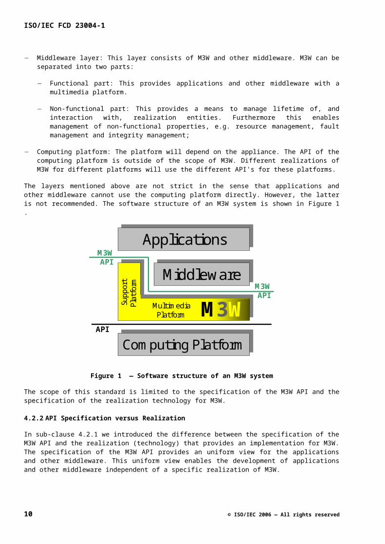
In an M3W system there are 3 distinct layers:
Applications: The type of applications will depend on the appliance.
Middleware layer: This layer consists of M3W and other middleware. M3W can be separated into two parts:
Functional part: This provides applications and other middleware with a multimedia platform.
Non-functional part: This provides a means to manage lifetime of, and interaction with, realization entities. Furthermore this enables management of non-functional properties, e.g. resource management, fault management and integrity management;
Computing platform: The platform will depend on the appliance. The API of the computing platform is outside of the scope of M3W. Different realizations of M3W for different platforms will use the different API's for these platforms.
The layers mentioned above are not strict in the sense that applications and other middleware cannot use the computing platform directly. However, the latter is not recommended. The software structure of an M3W system is shown in Figure 1 — Software structure of an M3W system.
ApplicationsApplications
Computing PlatformComputing PlatformAPI
M3WAPI
Supp
ort
Platfo
rm
MultimediaPlatform M3WMiddlewareMiddleware
M3WAPI
Figure 1 — Software structure of an M3W system
The scope of this standard is limited to the specification of the M3W API and the specification of the realization technology for M3W.
4.2.2 API Specification versus Realization
In sub-clause 4.2.1 we introduced the difference between the specification of the M3W API and the realization (technology) that provides an implementation for M3W. The specification of the M3W API provides an uniform view for the applications and other middleware. This uniform view enables the development of applications and other middleware independent of a specific realization of M3W.
8 © ISO/IEC 2006 — All rights reserved
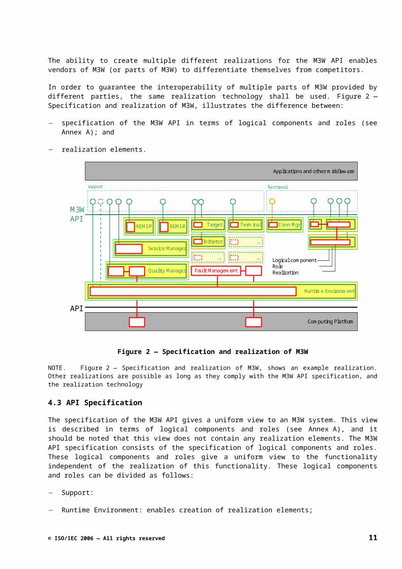
The ability to create multiple different realizations for the M3W API enables vendors of M3W (or parts of M3W) to differentiate themselves from competitors.
In order to guarantee the interoperability of multiple parts of M3W provided by different parties, the same realization technology shall be used. Figure 2 — Specification and realization of M3W, illustrates the difference between:
specification of the M3W API in terms of logical components and roles (see Annex A); and
realization elements.
M3WAPI
REMI-P REMI-R
Service Manager
Quality Manager
APIComputing Platform
Initiator
Target
…
Terminal
Fault Management
Runtime Environment
…
…
support
Applications and other middleware
functional
Conn Mgr
Logical componentRoleRealization
Figure 2 — Specification and realization of M3W
NOTE. Figure 2 — Specification and realization of M3W, shows an example realization. Other realizations are possible as long as they comply with the M3W API specification, and the realization technology
4.3 API Specification
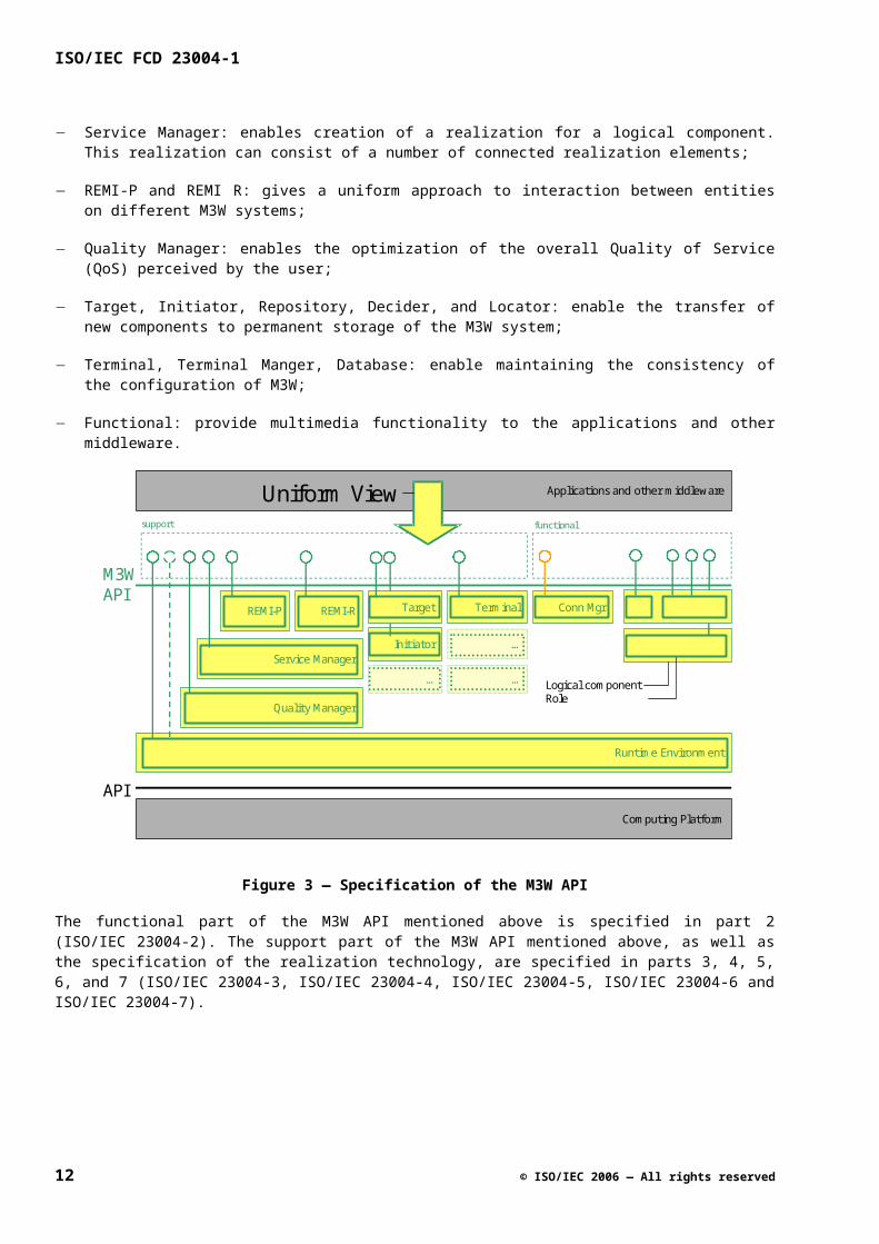
The specification of the M3W API gives a uniform view to an M3W system. This view is described in terms of logical components and roles (see Annex A), and it should be noted that this view does not contain any realization elements. The M3W API specification consists of the specification of logical components and roles. These logical components and roles give a uniform view to the functionality independent of the realization of this functionality. These logical components and roles can be divided as follows:
Support:
Runtime Environment: enables creation of realization elements;
Service Manager: enables creation of a realization for a logical component. This realization can consist of a number of connected realization elements;
REMI-P and REMI R: gives a uniform approach to interaction between entities on different M3W systems;
Quality Manager: enables the optimization of the overall Quality of Service (QoS) perceived by the user;
© ISO/IEC 2006 — All rights reserved 9
ISO/IEC FCD 23004-1
Target, Initiator, Repository, Decider, and Locator: enable the transfer of new components to permanent storage of the M3W system;
Terminal, Terminal Manger, Database: enable maintaining the consistency of the configuration of M3W;
Functional: provide multimedia functionality to the applications and other middleware.
M3WAPI
REMI-P REMI-R
Service Manager
Quality Manager
APIComputing Platform
Initiator
Target
…
Terminal
Runtime Environment
…
…
support
Applications and other middleware
functional
Conn Mgr
Logical componentRole
Uniform View
Figure 3 — Specification of the M3W API
The functional part of the M3W API mentioned above is specified in part 2 (ISO/IEC 23004-2). The support part of the M3W API mentioned above, as well as the specification of the realization technology, are specified in parts 3, 4, 5, 6, and 7 (ISO/IEC 23004-3, ISO/IEC 23004-4, ISO/IEC 23004-5, ISO/IEC 23004-6 and ISO/IEC 23004-7).
4.4 Realization Technology
4.4.1 Overview
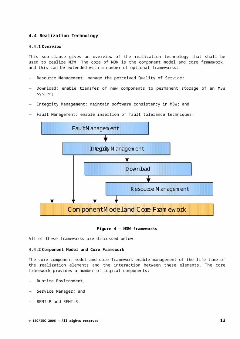
This sub-clause gives an overview of the realization technology that shall be used to realize M3W. The core of M3W is the component model and core framework, and this can be extended with a number of optional frameworks:
Resource Management: manage the perceived Quality of Service;
Download: enable transfer of new components to permanent storage of an M3W system;
Integrity Management: maintain software consistency in M3W; and
Fault Management: enable insertion of fault tolerance techniques.
10 © ISO/IEC 2006 — All rights reserved
Component Model and Core FrameworkComponent Model and Core Framework
Resource ManagementResource Management
DownloadDownload
Integrity ManagementIntegrity Management
Fault ManagementFault Management
Resource ManagementResource Management
DownloadDownload
Integrity ManagementIntegrity Management
Fault ManagementFault Management
Figure 4 — M3W frameworks
All of these frameworks are discussed below.
4.4.2 Component Model and Core Framework
The core component model and core framework enable management of the life time of the realization elements and the interaction between these elements. The core framework provides a number of logical components:
Runtime Environment;
Service Manager; and
REMI-P and REMI-R.
The Runtime Environment and Service Manager deal with the creation (instantiation) of realization elements. The Runtime Environment enables the creation of a single realization element (instantiation of services as is described in ISO/IEC 23004-3). The Service Manager enables the creation of (a number of connected) realization elements that realize a logical component.
The component model specifies what constitutes a component, executable component and service (see ISO/IEC 23004-3). Furthermore it specifies the interaction mechanisms for these entities, this includes:
Binding
Access to attributes of realization elements
Operation invocation
Navigation between interfaces
In short it specifies how to create realization elements and interact with them.
© ISO/IEC 2006 — All rights reserved 11
ISO/IEC FCD 23004-1
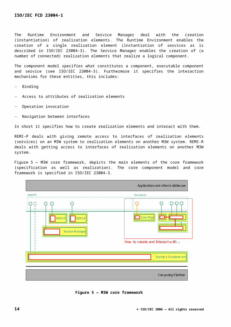
REMI-P deals with giving remote access to interfaces of realization elements (services) on an M3W system to realization elements on another M3W system. REMI-R deals with getting access to interfaces of realization elements on another M3W system.
Figure 5 — M3W core framework, depicts the main elements of the core framework (specification as well as realization). The core component model and core framework is specified in ISO/IEC 23004-3.
REMI-P REMI-R
Service Manager
Computing Platform
Runtime Environment
support
Applications and other middleware
functional
Conn Mgr
How to create and Interact with …
Figure 5 — M3W core framework
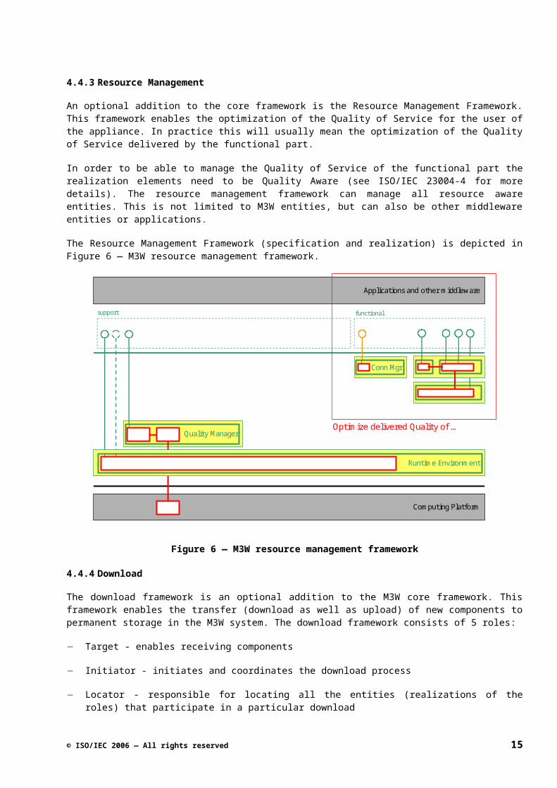
4.4.3 Resource Management
An optional addition to the core framework is the Resource Management Framework. This framework enables the optimization of the Quality of Service for the user of the appliance. In practice this will usually mean the optimization of the Quality of Service delivered by the functional part.
In order to be able to manage the Quality of Service of the functional part the realization elements need to be Quality Aware (see ISO/IEC 23004-4 for more details). The resource management framework can manage all resource aware entities. This is not limited to M3W entities, but can also be other middleware entities or applications.
The Resource Management Framework (specification and realization) is depicted in Figure 6 — M3Wresource management framework.
12 © ISO/IEC 2006 — All rights reserved
Quality Manager
Computing Platform
Runtime Environment
support
Applications and other middleware
functional
Conn Mgr
Optimize delivered Quality of …
Figure 6 — M3W resource management framework
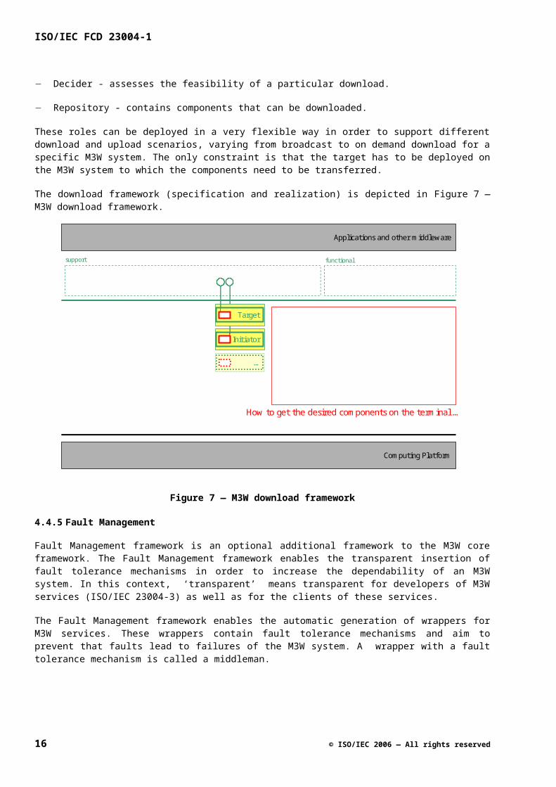
4.4.4 Download
The download framework is an optional addition to the M3W core framework. This framework enables the transfer (download as well as upload) of new components to permanent storage in the M3W system. The download framework consists of 5 roles:
Target - enables receiving components
Initiator - initiates and coordinates the download process
Locator - responsible for locating all the entities (realizations of the roles) that participate in a particular download
Decider - assesses the feasibility of a particular download.
Repository - contains components that can be downloaded.
These roles can be deployed in a very flexible way in order to support different download and upload scenarios, varying from broadcast to on demand download for a specific M3W system. The only constraint is that the target has to be deployed on the M3W system to which the components need to be transferred.
The download framework (specification and realization) is depicted in Figure 7 — M3W download framework.
© ISO/IEC 2006 — All rights reserved 13
ISO/IEC FCD 23004-1
Computing Platform
Initiator
Target
…
support
Applications and other middleware
functional
How to get the desired components on the terminal …
Figure 7 — M3W download framework
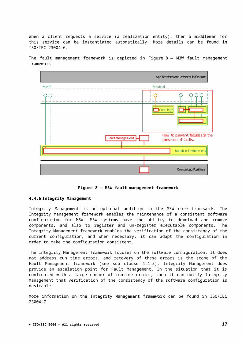
4.4.5 Fault Management
Fault Management framework is an optional additional framework to the M3W core framework. The Fault Management framework enables the transparent insertion of fault tolerance mechanisms in order to increase the dependability of an M3W system. In this context, ‘transparent’ means transparent for developers of M3W services (ISO/IEC 23004-3) as well as for the clients of these services.
The Fault Management framework enables the automatic generation of wrappers for M3W services. These wrappers contain fault tolerance mechanisms and aim to prevent that faults lead to failures of the M3W system. A wrapper with a fault tolerance mechanism is called a middleman.
When a client requests a service (a realization entity), then a middleman for this service can be instantiated automatically. More details can be found in ISO/IEC 23004-6.
The fault management framework is depicted in Figure 8 — M3W fault management framework.
14 © ISO/IEC 2006 — All rights reserved
Computing Platform
Fault Management
Runtime Environment
support
Applications and other middleware
functional
Conn Mgr
How to prevent failures in the presence of faults…
Figure 8 — M3W fault management framework
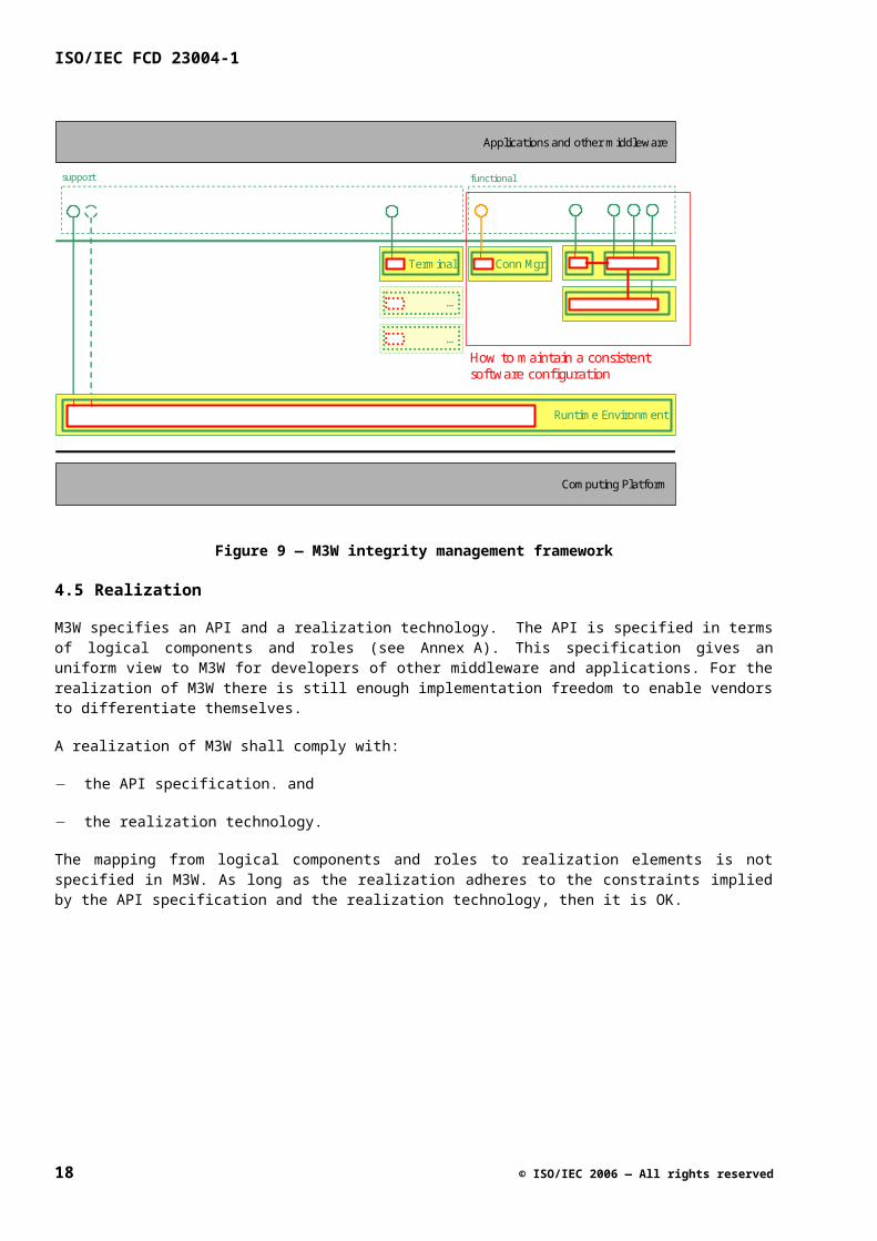
4.4.6 Integrity Management
Integrity Management is an optional addition to the M3W core framework. The Integrity Management framework enables the maintenance of a consistent software configuration for M3W. M3W systems have the ability to download and remove components, and also to register and un-register executable components. The Integrity Management framework enables the verification of the consistency of the current configuration, and when necessary, it can adapt the configuration in order to make the configuration consistent.
The Integrity Management framework focuses on the software configuration. It does not address run time errors, and recovery of these errors is the scope of the Fault Management framework (see sub clause 4.4.5). Integrity Management does provide an escalation point for Fault Management. In the situation that it is confronted with a large number of runtime errors, then it can notify Integrity Management that verification of the consistency of the software configuration is desirable.
More information on the Integrity Management framework can be found in ISO/IEC 23004-7.
© ISO/IEC 2006 — All rights reserved 15
ISO/IEC FCD 23004-1
Computing Platform
Terminal
Runtime Environment
…
…
support
Applications and other middleware
functional
Conn Mgr
How to maintain a consistentsoftware configuration
Figure 9 — M3W integrity management framework
4.5 Realization
M3W specifies an API and a realization technology. The API is specified in terms of logical components and roles (see Annex A). This specification gives an uniform view to M3W for developers of other middleware and applications. For the realization of M3W there is still enough implementation freedom to enable vendors to differentiate themselves.
A realization of M3W shall comply with:
the API specification. and
the realization technology.
The mapping from logical components and roles to realization elements is not specified in M3W. As long as the realization adheres to the constraints implied by the API specification and the realization technology, then it is OK.
16 © ISO/IEC 2006 — All rights reserved
x
GetX()SetX()
x
Attribute also accessible via service specific interface
x
GetX()SetX()
y = (2 x X)
…
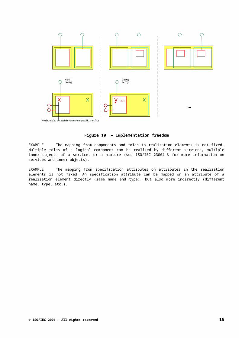
Figure 10 — Implementation freedom
EXAMPLE The mapping from components and roles to realization elements is not fixed. Multiple roles of a logical component can be realized by different services, multiple inner objects of a service, or a mixture (see ISO/IEC 23004-3 for more information on services and inner objects).
EXAMPLE The mapping from specification attributes on attributes in the realization elements is not fixed. An specification attribute can be mapped on an attribute of a realization element directly (same name and type), but also more indirectly (different name, type, etc.).
© ISO/IEC 2006 — All rights reserved 17
ISO/IEC FCD 23004-1
Annex A(informative)
API Specifications Reader’s Guide
A.1 The API Specification
A.1.1 Introduction
The purpose of this sub clause is to discuss some of the main concepts in connection with API specifications and to present the overall structure of an API specification.
A.1.2 Concepts
A.1.2.1 Interface Suites
The purpose of an API specification is to define a collection of software interfaces providing access to a coherent chunk of functionality. Such a collection of interfaces is referred to as an interface suite.
EXAMPLE The Analog Audio Decoding interface suite is a collection of interfaces providing access to Analog Audio Decoding functionality. Among other things, this interface suite contains an interface uhIAnaAdec for controlling audio decoding and an interface uhIAnaAdecSelector for controlling audio program selection.
A.1.2.2 Interfaces versus Functionality
The provision and use of interfaces should not be confused with the provision and use of functionality. Functionality is generally provided by means of a collection of interfaces (an interface suite). Generally speaking, the interfaces in this collection are ‘provides’ as well as ‘requires’ interfaces (from the point of view of the provider of the functionality).
EXAMPLE Providing Analog Audio Decoding functionality is not the same as providing the interfaces uhIAnaAdec and uhIAnaAdecSelector. The analog audio decoding and selection functionality is provided not only by means of the ‘provides’ interfaces uhIAnaAdec and uhIAnaAdecSelector but also by the ‘requires’ interface uhIAnaAdecNtf, which should be provided by the client of the functionality.
A.1.2.3 Logical Components
From a conceptual point of view, the functionality associated with an interface suite can be viewed as a black box that interacts with its environment through the software interfaces in the interface suite and other interfaces such as streaming interfaces. Specifying the behavior associated with the interfaces amounts to specifying the external behavior of this black box. Because the black box is conceptual it is also referred to as a logical component.
Since interfaces and their associated functionality are inseparable, the terms interface suite and logical component are often used in an interchangeable way. In a narrow sense, the term logical component is sometimes reserved for those interface suites that are direct building blocks of the M3W API and not just building blocks of other interface suites. Examples of the latter are the rcIUnknown and Pin Objects interface suites and the generic Notification interface suite. These interface suites never occur stand-alone but always in combination with other interface suites.
18 © ISO/IEC 2006 — All rights reserved
EXAMPLE When using the terms Video Mixing logical component and Video Mixing interface suite we usually mean the same thing. The focus in the former is on the Video Mixing functionality while the focus in the latter is on the Video Mixing interfaces, but these two aspects are closely related.
A.1.2.4 Logical Components and Service
The concept of a logical component should not be confused with that of a realization element. An API specification specifies functionality and the way that this functionality can be accessed by means of interfaces. It does not specify how this functionality should be implemented, and it does not even specify how it should be packaged. The functionality associated with the interfaces may be implemented in a single realization element, but could just as well be implemented in multiple realization elements, as part of one or more realization elements.
EXAMPLE An implementation of the Video Mixing logical component is referred to as a video mixer. The video mixer need not be a single service but could be a collection of services.
A.1.2.5 API Specifications as Contracts
There are two sides to functionality: the side of the providers and the side of the clients of the functionality. Classically an API is viewed as a single interface that allows a client to access functionality implemented by a provider. The API specification can then be viewed as a bilateral contract between the provider and the client defining the rights and obligations of both. M3W API specifications are based on a generalized version of the classical contractual paradigm: an API specification is viewed as a multi-lateral contract defining multiple mutually related interfaces. The concept of role is key to this generalized notion of contract.
A.1.2.6 Roles
A role identifies a contractual party, where each role acts as a provider of one or more interfaces, as a client of one or more interfaces, or as both. Each role has contractual rights and obligations associated with it. When developing code that implements or uses the API, the developer should make explicit which roles are to be played by the code. The rights and obligations specified for these roles in the API specification then define which API-implied requirements have to be satisfied by the code.
EXAMPLE Three roles identified in the Analog Audio Decoding logical component are: AnaAdec (decoder), AnaAdecSelector (program selector) and AnaAdecClient (client of the interfaces). This illustrates that in the specification of a logical component the responsibilities for providing the overall functionality of the logical component may be divided over several roles played by the logical component.
A.1.2.7 Roles and Realization Elements
Roles should not be confused with realization elements (services) although the names of roles may sometimes suggest otherwise. Roles define required/allowed behavior and do not define how that behavior should be realized. The correspondence between roles and service need not be one-to-one. For example, a single role can be implemented by multiple services, and a single service class can implement multiple roles.
The UML term for a role is abstract class, i.e. a class representing behavior and having no implementation. This implies that roles are (abstract) classes and not objects. At run-time there may be multiple instances of a role, i.e. multiple objects that play the role.
EXAMPLE In an object-oriented implementation the AnaAdecSelector role from the Analog Audio Decoding logical component is typically implemented by a co-class with the same name. Because an analog audio decoder/selector has multiple program selectors, multiple objects of type AnaAdecSelector will be created at run-time, each of which can be viewed as an instance of the AnaAdecSelector role.
© ISO/IEC 2006 — All rights reserved 19
ISO/IEC FCD 23004-1
A.1.3 Patterns
An API specification is itself a composition of more fine-grained specifications which define specification items such as constants, data types, roles, interfaces and methods. For each type of specification item fixed specification patterns are used, and these are discussed in the following sub clauses. Although different, all of these specification patterns have a common super-structure defined by a number of sections that occur in all specification patterns (and in fixed order). Being aware of this common structure makes it easier to understand the specifications. The common sub clauses are:
1) Signature
Contains the IDL definition of the specification item. The text in this sub clause occurs literally in the IDL definition of the API as a whole. The only exception is the Signature sub clause of a model type or constant, which consists of pseudo-IDL that will not be contained in the IDL of the API. Interface specifications do not have a Signature sub clause because the contents of this sub clause are essentially only the concatenation of the Signature sub clauses of the methods defined in the interface.
2) Qualifiers
Provides a list of qualifiers which are predefined keywords that can be associated with a specification item. Each qualifier represents a property or constraint that is being imposed on the specification item. The valid qualifiers for each specification item and their meaning are defined in Annex J, API Qualifiers. Qualifiers are similar to stereotypes in UML except that multiple qualifiers may be associated with a specification item. They are typically used as abbreviations for standard execution constraints (e.g. the qualifier single-threaded) or the specification of standard behavior (e.g. the qualifier subscribe-function).
EXAMPLE Three roles identified in the Analog Audio Decoding logical component are:
AnaAdec (decoder),
AnaAdecSelector (program selector) and
AnaAdecClient (client of the interfaces).
These illustrate the use of the following qualifiers:
Ana (for analog), and
Adec (for audio-decoder.
3) Description
Provides a short informal description of the specification item.
4) (Execution) Constraints
Defines restrictions that apply to the specification item.
Examples of these are restrictions on the set of allowed values of a data type (e.g. min-max constraints) and execution constraints that impose multi-threading constraints on the clients of interfaces. Note that several frequently occurring constraints (such as being single-threaded) have been defined as qualifiers, so these constraints are specified in the Qualifiers sub clause rather than the Constraints sub clause.
5) Remarks
20 © ISO/IEC 2006 — All rights reserved
Contains a list of remarks related to the specification item.
A.1.4 Structure of an API Specification
The idea of API specifications as contracts is reflected in the structure of an API specification which consists of the following sub clauses:
6) Concepts
This sub clause introduces the concepts associated with the functionality being specified and to define the vocabulary used in formulating the contractual rights and obligations.
7) Types & Constants
This sub clause defines types and constants that are used in the specification. Typical content would include: the definitions of data types that occur in the parameter lists of interface functions and the definitions of the specific error codes that can be returned by these functions.
8) Logical Component
This sub clause defines overall aspects of the logical component such as its structure, its diversity and its instantiation. A central position in this sub clause is taken by the “interface-role model” which is a UML class diagram showing all roles and interfaces and their mutual relations.
9) Roles
This sub clause specifies the roles that represent the functionality provided by the API. A ‘model-oriented’ style of specification is used, where attributes are used to represent state information associated with the roles. Interface functions operate using these attributes but roles can also modify them autonomously.
10) Interfaces
This sub clause contains the actual interface specifications, in particular the specifications of the functions that occur in the interfaces. These functions define the part of role behavior that can be controlled externally from the software. The common style of specification is (extended) pre- and postconditions.
11) Additional sub-clauses
Used to collect any relevant information that does not fit into any of the other sub clauses.
The structure and contents of the above sub clauses are discussed in more detail in the following sub clauses.
A.2 The ‘Concepts’ sub clause
A.2.1 General
The Concepts sub-clause introduces and discusses the functionality defined in the API specification in an informal and intuitive way. It explains the main terms and concepts that play a role, and indicates the context in which the functionality will be used. The concepts are typically illustrated using pictures and diagrams. The contents of this sub-clause are free format, and so the sub-clause has no predefined structure.
© ISO/IEC 2006 — All rights reserved 21
ISO/IEC FCD 23004-1
A.3 The ‘Types & Constants’ sub clause
A.3.1 General
The Types & Constants sub clause contains the specifications of all types and constants that play a role in the API specification, and that are not already specified in one of the base documents. The sub clause is divided into two parts.
The first part deals with the public types and constants which are the types and constants that are visible to the application programmer: their definitions occur in the IDL associated with the API.
The second part deals with the model types and constants which are the types and constants introduced for modeling purposes only: these types and constants will not occur in the IDL of the API.
Public and model types and constants are specified in essentially the same way except that the definitions of model types and constants can use additional data types. Each type is specified in a separate sub clause; the name of the type is used as the heading of this sub clause. Type specifications are discussed in A.3.3 and A.3.4.
Constants are specified in groups of related constants. Each group is defined in a separate sub clause; the name of the group (e.g. Error Codes) is used as the heading of this sub clause. In the case where a constant group consists of a single constant, then the name of the constant is used as the name of the constant group. Constant specifications are discussed in A.3.2.
A.3.2 Constant Specifications
A constant specification defines a group of related constants and consists of the following sub clauses, some of which are optional:
12) Signature
The IDL definition of the constants. In the case of model constants this may be pseudo-IDL.
13) Qualifiers
The qualifiers associated with the constants. An example is the error-codes qualifier which states that the constants being defined are error codes returned by functions. If there are no qualifiers then this sub clause will contain the word; ‘none’.
14) Description
A short informal description of the group of constants.
15) Constants (optional)
Contains a table providing a short informal description of each constant in the group. In case the group of constants being defined consists of a single constant this sub clause is omitted and the informal description of the constant is contained in the Description sub clause.
16) Remarks (optional)
Contains a list of remarks related to the constants.
A.3.3 Type Specifications
A type specification defines a data type and consists of the following sub clauses, some of which are optional:
22 © ISO/IEC 2006 — All rights reserved
17) Signature
The IDL definition of the data type. In the case of a model type this may be pseudo-IDL.
18) Qualifiers
The qualifiers associated with the type. Examples of frequently used qualifiers are the enum-element and enum-set qualifiers for enumerated data types; these are explained in A.3.4.
19) Description
A short informal description of the data type.
20) Values / Fields / Attributes
Contains a table providing a short informal description of each member of the data type. In the case of an enumerated type the members are the values being enumerated. In the case of a structure type the members are the fields of the structure. Entity types are modeling types that have attributes as members; they are discussed in A.3.5. The heading of this sub clause (if present) varies dependent on the kind of data type being defined.
21) Constraints
Defines restrictions that apply to the values of the data type. For example, when defining a structure type there could be a dependency between the values of the fields which can be expressed as a constraint.
22) Remarks (optional)
Contains a list of remarks related to the data type.
A.3.4 Enums and Enum Sets
Enumerated data types are frequently used in APIs. It is also common practice in C to use bitwise or-ing of enumerated values to represent sets of enumerated values. In common programming practice no distinction is made between the enumerated type and the set type which can lead to confusion. In API specifications the distinction between the two is explicitly made. The qualifiers enum-element and enum-set are used for this.
If the values of an enumerated type are meant to be used as elements of sets (bit vectors), the enumerated type gets the qualifier enum-element. In that case the values of the enumerated type are defined as powers of two.
Data types that represent sets of enumerated values are typedef-ed as UInt32 (32-bit bit vectors) and get the qualifier enum-set. Normal enumerated types whose values are not meant to be bitwise or-ed are defined as usual, without using a qualifier.
A.3.5 Model Types
Besides the normal data types that can occur in IDL, such as Int32, Bool, enum{...}, struct{...}, etc., M3W API specifications can also contain abstract data types that are used for specification purposes only. These data types are defined in the Model Types & Constants sub clause of the Types & Constants sub clause. The naming of model types is more liberal than that of public types and constants. Names of model types usually have no prefixes and suffixes such as uh and _t.
Model types are mainly used in the definitions of attributes associated with roles. Besides the normal IDL data types the following three modeling types are used in API specifications:
© ISO/IEC 2006 — All rights reserved 23
ISO/IEC FCD 23004-1
23) Set
A set type defines (possibly infinite) mathematical sets of values of a specific type. The notation setof{type} is used to denote the type of mathematical sets of values of type ‘type’. For sets the usual mathematical notations are used.
24) Map
A map type defines tables that map values of one type (the domain type) to values of another type (the range type). Values of this type, called maps, can be viewed as generalized arrays and identical notation is used for these types. An array can be viewed as a map whose domain type is a sub range of the integers starting at 0; in maps the domain and range types may be any type.
25) Entity
An entity type defines a collection of objects that may have attributes associated with them. In UML terms, an entity type is a class with public attributes only and no operations, and an entity is an instance of the class, i.e. an object. The notation entity{...} is used to declare an entity type where the attributes are declared as C-style variables inside the braces.
The notations and the specification pattern used for entities are similar to those used for roles (see A.5). Similar to the specification of role attributes, the attributes of an entity type are divided into independent attributes, whose value may in principle vary freely, and dependent attributes, whose value can be defined in terms of other values. An entity type, like a role, can also be defined as a specialization of another entity type.
A.4 The ‘Logical Component’ sub clause
A.4.1 General
The Logical Component sub clause specifies all aspects of the API functionality that relate to the logical component as a whole, i.e. those aspects that are not specific to a particular role, interface or function. This sub clause consists of four sub clauses:
26) Interface-Role Model
Defines the interface-role model which can be viewed as a graphical summary of the main contractual entities, in particular, the roles and interfaces and their mutual relations.
27) Diversity
Defines the parameters that can be set at instantiation time of the logical component.
28) Instantiation
Specifies the result of instantiating a logical component: the objects that are created and their initial state.
29) Execution Constraints
Defines concurrency-related constraints that apply to the logical component as a whole.
These sub clauses are discussed in more detail below.
24 © ISO/IEC 2006 — All rights reserved
A.4.2 Interface-Role Model
One of the explicit goals of the style of specification used in the API specifications is to improve the level of precision of the API specifications without becoming too formal. Besides using a contractual approach, this goal can be achieved by using a model-oriented style of specification based on a restricted use of UML. Model-oriented specifications define behavior in terms of a model which can be seen as a kind of abstract implementation. The interface-role model defined in the Interface-Role Model sub clause is an enhanced UML class diagram that acts as a graphical summary of the model used to specify the logical component. It shows the main entities in the model such as interfaces and roles while leaving out other entities such as attributes and constraints. (Constraints are dealt with elsewhere (in a non-graphical way)). Each API specification defines such an interface-role model.
The interface-role model consists of the following entities:
30) The interfaces defined in the API specification possibly including interfaces defined in the base documents. The interfaces are represented by ‘lollipops’.
31) The roles defined in the API specification possibly including roles defined in the base documents. The roles are represented as (abstract) UML classes.
32) The ‘provides’ and ‘requires’ (or use) relations between the roles and interfaces. The ‘provides’ relation is represented by the stick of a lollipop and the ‘requires’ relation by a UML dependency relation (a dotted arrow).
33) The specializes relation between roles, represented by the inverse UML generalization arrow. Role R2 specializing role R1 implies that all contractual rights and obligations that apply to R1 also apply to R2.
34) The streams associated with the roles. Streams are represented by small squares.
35) The input and output relations between roles and streams. The input relation is represented by a fat arrow connecting a stream and a role and the output relation by a fat line connecting a role and a stream.
36) The bounding box of the logical component represented by a grey box. What is inside the box is considered internal to the logical component and what is outside is considered external.
© ISO/IEC 2006 — All rights reserved 25
ISO/IEC FCD 23004-1
Figure 11 — Interface Role Model: Notations Used, shows an example of the use of an Interface Role Model. It provides an overview of the UML notations used in interface-role diagrams. The small white squares are classes representing streams. A stream may be associated with a role as an input, an output, or both, as indicated by the fat lines and arrows. The small white squares outside the grey box represent the external input and output streams and those inside the grey box represent internal streams introduced for modeling purposes only. In practice, the small white squares representing the streams are sometimes omitted and only the fat lines and arrows are shown. Note that the specialization relation, although shown as a relation between two client roles, will most often occur as a relation between the roles inside the grey box.
Figure 11 — Interface Role Model: Notations Used
Roles, interfaces and streams defined in base documents are not normally shown in the interface-role diagram except when they relate to roles that are specialized by roles defined in the API specification. The roles and interfaces defined in the rcIUnknown and Notification API specifications are exceptions in that they are not normally shown in the diagram even when being specialized.
Note that the interface-role model provides information on the navigability between the interfaces of the logical component. If two interfaces are provided (directly or indirectly) by the same role, the QueryInterface function of rcIUnknown can be used to navigate from one interface to another. If two interfaces are provided by two different roles this is not possible.
A.4.3 Diversity
The Diversity sub clause gives a survey of the diversity associated with the logical component being defined. The diversity of a logical component consists of all parameters that can be set at instantiation time of the logical component and that will not change during the lifetime of the logical component. It is divided into interface diversity, defining which interfaces are mandatory/optional when instantiating an instance of the logical component, and configuration diversity, defining other parameters that can be set at instantiation time. The latter are modelled by attributes of roles. The interface and configuration diversity are specified in separate sub clauses. There is a third sub clause which is used for specifying constraints on the diversity parameters.
26 © ISO/IEC 2006 — All rights reserved
A.4.3.1 Provided Interfaces
The Provided Interfaces sub clause contains a table defining, for each interface of the API, whether that interface is mandatory or optional. The Role column in this table, indicating the provider of an interface, is necessary because the same interface may occur on multiple roles, in particular when two roles specialize the same role defined in a base document.
Note that an interface IR being mandatory on a role R means that each instance of R has the obligation to provide IR. An interface IR being optional on a role R means that each instance of R has the right to provide IR but not the obligation. Note that if IR is optional on R, it could be mandatory on a role S that specializes R but not the other way around. At runtime the presence or absence of an interface can be checked by means of the QueryInterface function of the omnipresent rcIUnknown.
A.4.3.2 Configurable Items
The Configurable Items sub clause contains a table defining the configuration parameters that can be set when the logical component is instantiated. The parameters are modeled as role attributes (diversity attributes) that are defined in the Roles sub clause. Attributes referred to in this table may be constant as well as variable. If the attribute is variable, the value that is provided at instantiation time is interpreted as the initial value of the attribute. So, the initial value of the attribute is the configuration parameter, and not its current value (which may change).
Note that API specifications only specify which parameters can be set at instantiation time and not how they are set (e.g. by compile-time variables, properties in a database, parameters of an instantiation function, etc.). The mechanism used to set the configuration parameters is implementation-dependent.
A.4.3.3 Constraints
The Constraints sub clause specifies constraints that apply to the optional interfaces and configurable items. These constraints can be viewed as the precondition of the instantiation operation.
A.4.4 Instantiation
Instantiation refers to the process of creating instances of logical components. A logical component instance is not a single object (in the object-oriented sense), but an aggregate that may consist of several objects. The API specification makes no assumptions on the mechanisms used to create a logical component instance but specifies what the result of the instantiation of a logical component is. This result is specified in the Instantiation sub clause which consists of two sub clauses, one specifying which objects are created, and one specifying the initial state of these objects.
A.4.4.1 Objects Created
The Objects Created sub clause defines which objects are contained in a new instance of the logical component. This is done by means of a table that specifies for each object: its type (normally a role name); its name; and its multiplicity. The multiplicity n of an object x indicates how many instances of the object occur in the logical component instance. If n > 1 then x is interpreted as an array of objects of size n. The individual objects in the array are indicated as usual: x[0], x[1], ,,,, x[n - 1]. The entries in the Object column in the table act as global names that may be referred to in the rest of the specification.
A.4.4.2 Initial State
The Initial State sub clause specifies properties of the objects declared in the previous sub clause that are true in the initial state of the logical component instance, i.e. immediately after the instantiation of the logical component. Properties that follow from the diversity constraints are not repeated here, so that information should be added, in order to get the full specification of the initial state of the logical component instance. Note that certain aspects of the initial state may have been deliberately left unspecified, e.g. to create implementation freedom.
© ISO/IEC 2006 — All rights reserved 27
ISO/IEC FCD 23004-1
A.4.5 Execution Constraints
In the Execution Constraints sub clause, the execution constraints that apply to the logical component as a whole are specified. In particular, global constraints with respect to the multi-threading aspects of the logical component are specified here. For example, a constraint might be that clients may not concurrently access any function in any interface provided by any role that is part of the logical component. These constraints are not repeated in the other sub clauses that follow.
A.5 The ‘Roles’ sub clause
A.5.1 General
The Roles sub clause specifies the roles used in the API specification. Each role is specified in a separate sub clause that has the name of the role as its title. A role represents behavior associated with one or more interfaces. Which (‘provides’ and ‘requires’) interfaces are associated with a role can be seen in the interface-role model.
Roles are a means to define the observable behavior of the logical component, i.e. the behavior that can be observed at the external software and streaming interfaces of the logical component. What is observable and what is not, are defined by the boundaries of the logical component box in the interface-role diagram.
The behavior associated with a role can be divided into four aspects:
37) Function behavior: the behavior of the functions in the interfaces provided by the role.
38) Streaming behavior: the input-output behavior of the streams associated with the role.
39) Active behavior: autonomous behavior that is visible at the ‘provides’ and ‘requires’ interfaces associated with the role.
40) Instantiation behavior: behavior displayed at instantiation time of the logical component.
Only the streaming and active behavior are specified in the Roles sub clause. Instantiation behavior is specified in the Logical Component sub clause and function behavior is specified in the Interfaces sub clause; see Figure 12 — Role Behavior and the Sub Clauses Where it is Specified.
Figure 12 — Role Behavior and the Sub Clauses Where it is Specified
28 © ISO/IEC 2006 — All rights reserved
NOTE Roles are pure specification artefacts. When implementing a logical component the only requirement is that the observable behavior of the logical component is consistent with the observable role behavior.
NOTE Role behavior is realized dynamically by instances of the role, i.e. by objects playing the role. So a role should not itself be viewed as an object, but rather as a class that may have several instances at run-time. From a contractual point of view, the specification of the role can be viewed as the set of rights and obligations to be satisfied by the code of that class.
A.5.2 Role Specifications
A role specification consists of the following sub clauses, some of which are optional:
41) Signature
The pseudo-IDL definition of the role which defines the attributes associated with the role. Attributes can be viewed as variables representing the abstract state of a role instance. They play an essential role in the model-oriented style of specification used in the API specifications.
42) Qualifiers
The qualifiers associated with the role.
43) Description
A short informal description of the role.
44) Independent Attributes
Contains a table providing a short informal description of each independent attribute. An independent attribute is an attribute whose value may in principle vary freely.
45) Dependent Attributes
Contains a table providing a short informal description of each dependent attribute. A dependent attribute is an attribute whose value can be expressed in terms of other entities, in particular the values of independent attributes. The description of the dependent attribute includes a definition of the value of the attribute.
46) Invariants
Provides a list of invariants. An invariant is an assertion about the role that is always true from the external observer’s point of view. The assertion is typically formulated in terms of the attributes of the role. In reality, the assertion may temporarily be violated.
47) Instantiation
Provides a description of how instances of the role are created. Usually instances of a role are created at instantiation time of a logical component only. In some cases instances of a role can also be created dynamically after the instantiation of the logical component, in particular by using interface functions that act as “constructors” of the role. In that case a list of the names of these constructors is provided.
48) Streaming Behavior
A description of the streaming behavior of the role, i.e. the input-output behavior of the streams associated with the role.
49) Active Behavior
© ISO/IEC 2006 — All rights reserved 29
ISO/IEC FCD 23004-1
A description of the active behavior of the role, i.e. autonomous behavior that is visible at the interfaces associated with the role.
50) Execution Constraints
Defines concurrency-related constraints that apply to the role, in particular to the collection of interfaces associated with the role. These constraints are not repeated in the specifications of these interfaces.
51) Remarks (optional)
Contains a list of remarks related to the role.
A.5.3 Role Signatures
The role signature can be viewed as the IDL of the role. It defines the structure of a role in the same way that IDL defines the structure of an interface. More specifically, the role signature defines which roles are specialized by the role and which attributes are associated with the role. From a contractual point of view a role S specializing a role R amounts to S inheriting all rights and obligations specified for R, including all attributes of R.
Attributes can be viewed as variables representing the abstract state of a role instance. The behavior of the logical component (see Figure 12 — Role Behavior and the Sub Clauses Where it is Specified) is specified in terms of this abstract state. Typically, external calls of interface functions will change the values of attributes and thereby influence the streaming and active behavior of a role. Conversely, the values of attributes may change autonomously as a consequence of the streaming and active behavior, which in turn may influence the behavior of other roles.
Attributes are introduced for modeling purposes only and should not be confused with implementation variables. They correspond to UML attributes but are not indicated in the interface-role model (which is an extended UML class diagram).
Note that attributes inherited from base roles (roles defined in base documents) are not re-declared in the signature. The optional const keyword indicates that the value of an attribute is constant during the lifetime of a role instance. It does not imply that the value of the attribute is the same for different role instances.
A.5.4 Independent and Dependent Attributes
The attributes associated with a role are divided into two types: those whose value may be defined or changed independently of all other attributes, and those whose value is a function of the values of other attributes. These two types are referred to as independent and dependent attributes. The difference makes sense because when specifying state transitions, only the changes to the values of the independent attributes have to be specified; the values of the dependent attributes follow automatically.
Independent attributes can be viewed as variables whose value can be modified. The independent attributes are listed in a table containing the name of each independent attribute and a short description of the meaning of the attribute.
The value of a dependent attribute can be expressed in terms of other entities, in particular the values of independent attributes. Dependent attributes can be viewed as parameterless functions whose value can be computed.
Dependent attributes are listed in a separate table similar to the dependent attributes. The difference is that the table also defines the value of each attribute (as part of the description of the attribute).
Sometimes it is known that an attribute is dependent on other entities without knowing what the exact dependencies are. This happens particularly with attributes that model signal properties; their value depends on the contents of the signal. In these cases the value of the attribute is only defined informally.
30 © ISO/IEC 2006 — All rights reserved
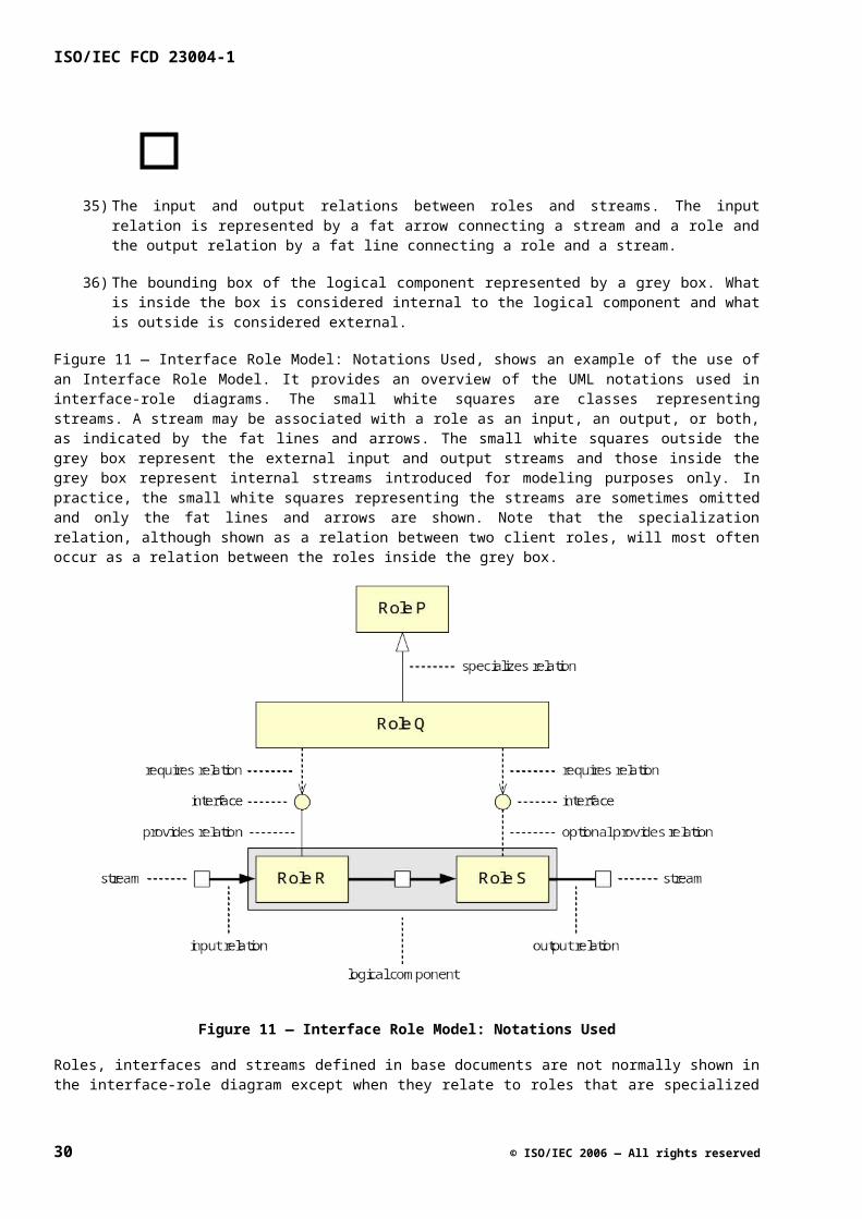
Dependent attributes are sometimes called auxiliary or convenience attributes. We can, in principle, do without them by repeating the expression defining the value of a dependent attribute every time we have to refer to that value, but the appropriate use of dependent attributes has a positive effect on both the size and the maintainability of an API specification.
A.5.5 Streaming Behavior
API specifications are meant to specify software interfaces, i.e. interfaces that can be used by software developers to develop applications on top of a platform. Many of the M3W API interfaces are streaming-related; they are used to control or provide information about streaming functionality. There is no way such interfaces can be defined without referring to streaming functionality. On the other hand, it is not the purpose of the M3W API specifications to provide detailed specifications of the streaming itself. The API specifications define software interfaces that are common to all platform instances. In a concrete platform instance, these specifications are augmented with additional information concerning performance, resource usage, streaming algorithms used, etc.
The purpose of the Streaming Behavior sub clause is to define the streaming behavior associated with the role at a level of abstraction that is sufficiently concrete to define the effect of the functions in the interfaces, and that is sufficiently abstract to make the interface generally applicable to different platform instances. In certain special cases this may mean that streaming behavior is specified in detail, but in most cases streaming behavior is modeled abstractly with a reference to standards for further details. The description of streaming behavior starts in the interface-role model diagram where the input and output streams are indicated, together with possible internal streams. The input and output streams are weakly typed. The description of how an input stream is transformed into an output stream is generally informal, where role attributes may be used to represent stream content.
A.5.6 Active Behavior
Besides autonomously performing streaming functions, instances of roles may also autonomously perform software functions. A typical case is the notification of events detected in input streams. Autonomous behavior is often specified in terms of an event-action table that connects events that may occur to actions performed by a role instance. The events can be streaming-related events but also software-related events such as timer events. The actions can be calls to functions in ‘requires’ interfaces or modifications of attributes. Roles which have no active behavior are passive; they do not actively influence the behavior of other roles.
Note that even though event notification is conceptually part of the active behavior associated with a role, most event notifications supported by a role are not listed in the event-action table. The reason is that the most common form of event behavior, an event leading to a notification of all subscribers of the event, is already specified in the general notification specification. This behavior is not repeated for every single event in the event-action table. The description of the event and the conditions under which the event is raised are described in the specification of the corresponding callback function. Some events are special in that they may have additional effects besides notifying clients. Only these non-standard event notifications, together with other autonomous behavior of role instances, are specified in the Active Behavior sub clause.
A.5.7 Actor Roles
In the interface-role model of a logical component, roles are introduced not only for the objects that provide the functionality of the logical component, but also for the objects that use the functionality, i.e. the clients of the logical component. The reason is that, from the contractual point of view, not only the providers, but also the users of the logical component may have to satisfy certain obligations. The latter obligations are part of the contract, and are associated with client roles that model the users of the logical component. Examples of client obligations are that a client has to provide a notification interface, or that it should not call certain functions under certain conditions.
From the specification point of view, client roles are usually much simpler than the provider roles of a logical component. A client role is typically characterized by having no attributes and no streaming behavior while its active behavior consists of providing stimuli only, i.e. of calling functions in interfaces of the logical component (as indicated in the interface-role model), without any a priori assumptions on when these calls occur. The
© ISO/IEC 2006 — All rights reserved 31
ISO/IEC FCD 23004-1
qualifier actor is used to indicate this type of role and the streaming and active behavior as well as the attribute sub clauses are omitted in the specification. Furthermore, no assumptions are made on how instances of an actor role are created.
A.6 The ‘Interfaces’ sub clause
A.6.1 General
The Interfaces sub clause contains specifications of all interfaces that are part of the API. The bulk of the specification of an interface consists of the specifications of the individual functions that constitute the interface. Each interface is specified in a separate sub clause that has the name of the interface as its title. The structure and contents of an interface specification are discussed in A.6.2.
Each function in an interface is specified in a separate sub clause of the interface specification. The structure and contents of a function specification are discussed in A.6.3. The style of specification used is extended pre- and postconditions which is further explained in A.6.4.
There are two types of interfaces: control interfaces and notification interfaces, which are dealt with slightly differently at the specification level. The differences between these two types of interface specifications are discussed in A.6.5.
Some frequently occurring types of functions are dealt with in a special way. This includes some standard functions relating to event subscription (discussed in A.6.6) and asynchronous functions (discussed in A.6.7). Finally, in A.6.8 we explain the “bullet notation” that is frequently used in function specifications.
A.6.2 Interface Specifications
An interface specification defines either a new interface or an interface that is specialized by the logical component. In the case of a new interface, the name of the sub clause defining the interface is equal to the unqualified interface name, e.g. uhIAnaAdec. In the case of a specialized interface, the name of the role providing the interface is added as a prefix to the interface name, using “::” as a separator. For example, “AnaAdec::uhIPinObjects” can be read as “the interface uhIPinObjects as specialized by the role AnaAdec”. The reason for this convention is that there may be multiple roles that specialize the same interface. Each of these specializations is described in a separate sub clause.
An interface specification consists of the following sub clauses, some of which are optional (which?).
52) Qualifiers
The qualifiers associated with the interface. An example of a frequently used qualifier is callback which marks the interface as a callback interface; the typical example of a callback interface is a notification interface.
53) Description
A short informal description of the interface.
54) Interface ID
The globally unique identifier associated with the interface.
55) Execution Constraints
Defines concurrency-related constraints that apply to the interface, in particular to the collection of functions in the interface. These constraints are not repeated in the specifications of these functions.
32 © ISO/IEC 2006 — All rights reserved
56) Remarks
Contains a list of remarks related to the interface.
57) Function specifications
Specifications of the individual functions in the interface, each in a separate sub clause. The standard functions inherited from the rcIUnknown interface (QueryInterface, AddRef and Release) are omitted.
There is no separate sub clause defining the signature (IDL representation) of the interface, because the signature can be generated automatically from the name of the interface, the interface ID and the signatures of the functions in the interface.
The above template is used for new as well as specialized interfaces. The only difference for specialized interfaces is that there are no specifications for those functions that are inherited as is from the base interface. Only those functions whose specification has changed by the specialization get a separate specification that overrides the old specification.
A.6.3 Function Specifications
Except for one detail (explained in A.6.4), the structure of a function specification is fairly standard. The style of specification can be characterized as extended pre- and postconditions. The specification of a function is subdivided into the following sub clauses, some of which are optional (which?):
58) Signature
The IDL definition of the function. This is essentially the C prototype of the function with some extra information, e.g. indicating which parameters are in-parameters and which ones are out-parameters.
59) Qualifiers
The qualifiers associated with the function. These qualifiers are often execution-related. For example, the “single-threaded” qualifier indicates that the number of threads that may concurrently execute the method is at most one.
60) Description
A short informal description of the function.
61) Parameters
Short informal descriptions of the parameters of the function, arranged in a table.
62) Return values
Short informal descriptions of the values that can be returned by the function, arranged in a table. In M3W API control interfaces the return values are almost always error codes; functions in notification functions do not normally return values. If the function returns only standard error codes, the table is omitted and the keyword “Standard” is used instead.
63) Precondition
Defines an assertion that should be true immediately before execution of the function starts. Contractually speaking, it is the obligation of the caller of the function to make sure this is the case.
64) Action
© ISO/IEC 2006 — All rights reserved 33
ISO/IEC FCD 23004-1
Describes the “abstract action” performed by the callee when the function is called. This action typically indicates which role attributes are modified by the function and/or which out-calls are performed by the function.
65) Postcondition
Defines an assertion that is true immediately after execution of the function finishes. Contractually speaking, it is the obligation of the callee to make sure this is the case.
66) Remarks (optional)
Contains a list of remarks related to the function.
A.6.4 Preconditions, Actions and Postconditions
An inherent restriction of classical pre- and postcondition specifications is that they can only be used to specify constraints on the states, before and after the execution of a function. They cannot be used to specify constraints on what should happen between these two states, i.e. during the execution of the function. A common approach is to allow anything to happen during the execution as long as the postcondition is not violated. This approach leads to underspecification of functions because we normally do not want a function to modify arbitrary variables or call arbitrary functions during its execution, even if the postcondition is met in the end. Furthermore, we sometimes want to express that certain observable actions should occur during the execution of a function, which is hard or even impossible to express in a postcondition. Typical examples of such actions are out-calls (such as callbacks) and synchronization actions (blocking).
The above problem is solved in API specifications by using extended pre- and postcondition specifications that allow observable behavior during the execution of a function to be specified in terms of an abstract action. The action is described in a way similar to ordinary code but using more abstract non-deterministic constructs that leave a lot of implementation freedom. The action is generally simple, though it can be used to specify more complex behavior as well, such as out-calls and synchronization.
A typical construct used in formulating abstract actions is Modify x, where x is some attribute (see the example above). Modify x should be interpreted as “change the state of the logical component in such a way that no state variable other than x is modified”. The new value of x is typically specified in the postcondition, where we do not have to specify that other variables have not been modified. In order to refer to the old value of x in the postcondition, the notation x’ is used. So, in the example above, when the notation mixer.blanked’ would have been used in the postcondition, it would refer to the value of mixer.blanked immediately before the call of the BlankOutput function. The Modify clause for an out-parameter of a function is omitted because the right to modify the value of the parameter is implicit in the [out] attribute associated with the parameter.
Each extended pre- and postcondition specification of a function can be interpreted as a mini-contract between the caller and callee of the function, as indicated in Figure 13 — Contractual Interpretation ofExtended Pre- and Postcondition Specifications.
Figure 13 — Contractual Interpretation of Extended Pre- and Postcondition Specifications
34 © ISO/IEC 2006 — All rights reserved
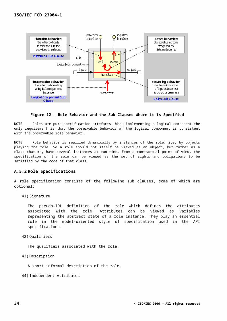
A.6.5 Control and Notification Interfaces
Generally speaking, a logical component provides two types of functionality: (streaming) control and (event) notification. The control functionality is provided by means of one or more control interfaces that are provided by the logical component and that allow a client to influence the behavior of the logical component by calling functions. The notification functionality is provided by one or more notification interfaces that are provided by the client and that allow the logical component to notify the occurrence of events to the client by calling functions.
Although the same layout is used for defining control and notification interfaces, they are dealt with differently at the specification level. The main reason for this is that, from the point of view of a logical component, a control interface is a ‘provides’ interface and a notification interface is a ‘requires’ interface. The specification of a control interface will define precisely what the effect of each function in the interface is. The specification of a notification interface, on the other hand, will usually not define what the effect of a notification function is; that is up to the client implementing the interface. Instead, the specification will describe when the function will be called, i.e. which event will cause the function to be called by the logical component.
Notification interfaces can be recognized by their name ending in Ntf. Typically, the name of a notification interface is equal to the name of the corresponding control interface extended with Ntf.
A.6.6 Subscribe, Unsubscribe and OnSubscriptionChanged
In order to make a logical component notify the occurrence of an event to a client, the client should first subscribe to the event. Each notification interface therefore has an associated control interface that among other functions contains two standard functions Subscribe and Unsubscribe. There is also one standard function OnSubscriptionChanged in each notification interface which is used to notify the client that its subscription has changed (because subscription is asynchronous). Because the specifications of these three functions have a standard pattern, their specifications are abbreviated using special qualifiers.
A.6.7 Asynchronous Functions
An asynchronous function can be viewed as a function with a delayed effect. The behavior of such a function can be separated into a synchronous part, i.e. the behavior between call and return of the function, and an asynchronous part, i.e. the behavior after returning from the function. Completion of the asynchronous action is usually reported by means of a notification allowing the caller of the function to synchronize with completion of the asynchronous effect of the function.
Because asynchronous functions occur frequently, a special extension of the pre-action-post format is used for specifying them. The synchronous part of an asynchronous function is specified in the same way as a synchronous function (except for the qualifier asynchronous). The asynchronous part is specified by means of an additional action-postcondition pair specifying the effect of the asynchronous action performed by the function.
The following notation is used in the Asynchronous Action clause to indicate the (asynchronous) act of notifying all subscribers to a specific event:
Notify OnEvent(*,...)
The asterisk refers to the observer-specific cookie and the ellipses to the event-specific data that is being passed.
The absence of the synchronous Action and Postcondition clauses in an asynchronous function specification are equivalent to the synchronous action being None and the synchronous postcondition being True. In this case the function does not have an immediate effect, but a delayed effect only.
The asynchronous action that is the consequence of calling an asynchronous function is part of the active behavior of the logical component. Because this action is already specified in the asynchronous function
© ISO/IEC 2006 — All rights reserved 35
ISO/IEC FCD 23004-1
specification, its specification is not repeated in the specification of the active behavior of the role that provides the function.
A.6.8 Bullet Notation
Throughout the API specification bullets and indentation are used to structure possibly complex assertions and expressions and restrict the number of parentheses as much as possible. The items in a bullet list that represents an assertion (such as an invariant, precondition or postcondition) are conceptually connected by logical AND operators. The items in a bullet list that represents an action are conceptually connected by sequential composition operators (semicolons, in C terms). Start and end of indentation logically introduce an opening and closing bracket, respectively.
A precondition such as:
Precondition
Assertion1
If( Assertion2 )
Assertion3
Assertion4
is equivalent to:
Precondition
Assertion1 && If( Assertion2 ) { Assertion3 && Assertion4 }
Likewise, an action clause such as:
Action
Action1
Action2
Modify
Variable1
Variable2
is equivalent to
Action
Action1; Action2; Modify { Variable1, Variable2 }
36 © ISO/IEC 2006 — All rights reserved
Annex B(normative)
Basic Types & Constants
B.1 Introduction
The data types that play a role in the M3W API can be subdivided into three categories:
67) Data types that are specific to an interface suite. These data types are defined in the API specification of the interface suite.
68) Data types that pertain to a group of functionally related interface suites, such as “video types” and “audio types”. These data types are specified in separate API specifications for each functional group.
69) Data types that are common to all interface suites. These data types, referred to as basic types, are defined in this API specification.
In defining the data types we will not use C data types such as int, long, float, etc. since the interpretation of these types, and in particular their size, may be implementation-dependent. Instead we use the names below to indicate implementation-independent types; these names (enclosed by angle brackets) are self-explanatory:
• <n-bit signed integer> (n = 8, 16, 32)
• <n-bit unsigned integer> (n = 8, 16, 32)
B.2 Public Types & Constants
B.2.1 Int8
Signature
typedef <8-bit signed integer> Int8, *pInt8;
Qualifiers
None.
Description
8-bit signed integer values.
B.2.2 Int16
Signature
typedef <16-bit signed integer> Int16, *pInt16;
© ISO/IEC 2006 — All rights reserved 37
ISO/IEC FCD 23004-1
Qualifiers
None.
Description
16-bit signed integer values.
B.2.3 Int32
Signature
typedef <32-bit signed integer> Int32, *pInt32;
Qualifiers
None.
Description
32-bit signed integer values.
B.2.4 UInt8
Signature
typedef <8-bit unsigned integer> UInt8, *pUInt8;
Qualifiers
None.
Description
8-bit unsigned integer values.
B.2.5 UInt16
Signature
typedef <16-bit unsigned integer> UInt16, *pUInt16;
Qualifiers
None.
Description
16-bit unsigned integer values.
B.2.6 UInt32
Signature
typedef <32-bit unsigned integer> UInt32, *pUInt32;
38 © ISO/IEC 2006 — All rights reserved
Qualifiers
None.
Description
32-bit unsigned integer values.
B.2.7 Double
Signature
typedef <64-bit double precision floating point> Double, *Double
Qualifiers
None
Description
Compliant with IEEE standard:
The IEEE double precision floating point standard representation requires a 64 bit word, which may be represented as numbered from 0 to 63, left to right. The first bit is the sign bit, S, the next eleven bits are the exponent bits, 'E', and the final 52 bits are the fraction 'F'
B.2.8 Float
Signature
Typedef <32-bit single precision floating point> Float, *Float
Qualifiers
None
Description
Compliant with IEEE standard:
The IEEE single precision floating point standard representation requires a 32 bit word, which may be represented as numbered from 0 to 31, left to right. The first bit is the sign bit, S, the next eight bits are the exponent bits, 'E', and the final 23 bits are the fraction 'F'.
B.2.9 Char
Signature
Typedef <8-bit character> Char, *Char
Qualifiers
None
Description
8 bit character
© ISO/IEC 2006 — All rights reserved 39
ISO/IEC FCD 23004-1
B.2.10 Void
Signature
typedef void Void, *pVoid;
Qualifiers
None.
Description
The Void type has no values: it is used to indicate the absence of a return value or parameter list in functions. The pVoid type represents untyped pointer values.
B.2.11 Bool
Signature
typedef <32-bit unsigned integer> Bool, *pBool;
Qualifiers
sub-type
Description
The Boolean values (True and False).
Constraints
For each Bool b
b == 0 || b == 1
B.2.12 Boolean Values
Signature
const Bool True = 1;
const Bool False = 0;
Qualifiers
None.
Description
These constants define the values contained in the data type Bool.
40 © ISO/IEC 2006 — All rights reserved
Constants
Table A.1
Name Description
True The value representing the “true” condition.
False The value representing the “false” condition.
B.2.13 String
Signature
typedef <8-bit signed integer> *String, **pString;
Qualifiers
None.
Description
Null-terminated strings of 8-bit characters.
B.2.14 UUID
Signature
typedef <128-bit unique identifier> UUID, *pUUID;
Qualifiers
None.
Description
128-bit unique identifier, compliant with the COM specification [13].
B.2.15 pIUnknown
Signature
typedef <interface instance> *pIUnknown;
Qualifiers
None
Description
Interface reference
© ISO/IEC 2006 — All rights reserved 41
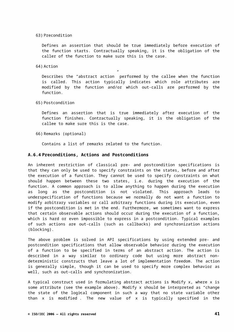
ISO/IEC FCD 23004-1
B.2.16 rcResult
Signature
typedef UInt32 rcResult, *prcResult;
Qualifiers
None.
Description
Error codes as returned by most M3W API functions except notification functions.
B.2.17 Error Codes
Signature
const rcResult RC_OK = 0;
Qualifiers
error-codes
Description
These constants define common error codes returned by M3W API functions.
42 © ISO/IEC 2006 — All rights reserved
Constants
Table A.2
Name Description
RC_OK Indicates successful execution of a function.
© ISO/IEC 2006 — All rights reserved 43
ISO/IEC FCD 23004-1
44 © ISO/IEC 2006 — All rights reserved
Annex C(normative)
API Evolution Rules
C.1 Introduction
C.1.1 Summary
An API Specification document contains a number of API elements. It contains specifications of data types and constants. These data types and constants are used in the functions of interface specifications. Instances of these interfaces are provided by roles. A logical component specification again consists of a number of roles.
The purpose of this document is to describe the evolution rules of these API elements. These rules are based on existing rules where applicable, e.g. the COM evolution rule [13]. Additional rules are needed since additional concepts like Logical Components and Roles are used.
C.2 Requirements
M3W contains a large set of interface and logical component specifications, which have to be managed and maintained. This API is used by a number of parties, both for providing server implementations and for building client applications on top of the API. In general, it is not known which party depends on which part of the API.
The API will never be complete; it will evolve over time to support new features. This requires, for example, new interface specifications. Consequently, new releases of the API will be needed over time. The different parties using the API will have different demands towards the evolution of the API, e.g. different timings of releases.
In general, it must be possible to evolve the API (adding new functionality, removing obsolete functionality), whilst limiting the impact on the clients and the servers. Below, the main requirements are listed that form the foundation for the evolution rules described in this document:
It must be possible to add a new function/feature to the API without affecting the existing clients that do not need that feature. A client should not have to be recompiled, but recompilation against the new API should also be no problem. This will help to limit the porting effort for the clients.
It must be possible to introduce new functionality gradually. Since almost all services in the API are provided by the servers, adding new functionality will result in an implementation effort for the servers. They should have a reasonable time window for adding the new functionality to the implementation, to avoid lock-step evolution (i.e. the servers do not have to change at the same time the API changes). This also holds for the clients in case of notification interfaces.
It must be possible to remove obsolete functionality from the API. Removing functionality means for a server that part of the implementation can be removed. Removing functionality means for a client that the depending code has to be rewritten. The clients should have a reasonable time to do that, to avoid lock-step evolution.
Not only must it be possible to combine an old client (software above the API requiring an older version of the API) with a new server (software below the API providing a newer version of the API), it must also be possible to combine a new client with an old server. The latter combination, for example, rules out
© ISO/IEC 2006 — All rights reserved 45

ISO/IEC FCD 23004-1
changing an interface specification by adding a function: the call to that function by the new client would fail for the old server. When the new client requires functionality that is not yet available on the old server, the client must be able to detect this and possible degrade its functionality.
It must be possible to touch a logical component specification document to do small fixes that do not directly influence the clients (syntax nor semantics). It should be immediately clear on the document that the change is not relevant for the code depending on that logical component.
C.3 Lifecycle
In this clause, the lifecycles of logical component specifications, interface specifications and documents are described.
C.3.1 Lifecycle of Logical Component Specification
A logical component specification has a lifecycle containing a number of phases (see Figure B.1 — Logicalcomponent specification lifecycle). Changes on the logical component specification are handled differently depending on the phase it is in.
Figure B.1 — Logical component specification lifecycle
The Change Control Board decides on whether a new logical component specification is needed (based on commercial requirements / features). A logical component specification will be defined and founded at a certain date (Foundation date). After that, the logical component specification will be used and tested in e.g. one lead (product) project that requested the new feature to be exposed by the logical component specification. The reason for having this Testing phase is that practice has proven that a logical component specification is typically not correct until implemented and used. During this phase, the logical component specification may change when the few parties involved agree. To avoid problems where other parties perceive the logical component specification already as final, this specification is not part of an UHAPI release. Changes in the specification are decided upon by the parties involved. After a logical component specification is “proven” usable, it is published and is put under change control (Published phase). A change requires a CR that is agreed upon by the controlling CCB. From this point in time, multiple projects can use the logical component specification.
At a certain point in time, a logical component specification becomes obsolete (Obsolete date). Since multiple parties (with their own development lifecycles) can depend on that logical component specification, there will
46 © ISO/IEC 2006 — All rights reserved
be a time window in which the logical component specification is to be phased out (typically it will be replaced by a new one). An obsolete logical component specification will be marked in the documentation as being obsolete. No maintenance will be accepted on an obsolete logical component specification. The lifetime of an obsolete logical component is typically between 0.5 and 1.5 years. The decision about the exact time will be taken case by case depending on impact of the change to the various involved parties.
C.3.2 Lifecycle of Interface Specification
The state of the logical component specification is related to the state of the interface specifications it contains. Initially, both the logical component specification and its owned interface specifications will follow the same phases as illustrated in Figure B.1 — Logical component specification lifecycle. For a logical component specification in phase Published, it may be decided to experiment with an additional interface for the logical component. As a consequence, a new version of this logical component specification goes back to the Testing phase. This version of the logical component specification will however not be part of a release of the API, since it is in the Testing phase. Instead, the previous (published) version of the logical component is part of the API release. When the additional interface specification becomes published, there will be a new published version of the logical component specification, replacing the previous published version.
If an interface specification becomes obsolete, this state will be clearly marked on the interface in the document of the logical component specification. This way, the users of the API are warned that this interface specification will be removed from the logical component specification within a certain time window. The lifetime of an obsolete interface is similar to that of an obsolete logical component (between 0.5 and 1.5 years).
C.3.3 Document Lifecycle
A logical component specification document has a number of states. These states can be related to the logical component specification lifecycle as follows:
Table B.1 —. Document states and logical component specification states
Document state Logical component specification state
Draft Definition phase
Accepted Testing phase
Approved Published phase
In addition to these states, ‘Proposed’ is also used. This state indicates that the document is ready for a review to move from Draft to Accepted.
A document also has a version number. This version number is increased in case of an evolution steps. How this number is increased is explained in clause C.4.4 on the evolution of logical components.
When evolving the document, several steps can be made to update it, e.g. for various reviews. These intermediate steps should not increase the version number. To still be able to identify a certain document, an additional revision number is used that is increased for each intermediate step.
C.4 Evolution of API Elements
In this clause, we first describe the general evolution rules, followed by how this impacts the various elements of the API.
© ISO/IEC 2006 — All rights reserved 47
ISO/IEC FCD 23004-1
C.4.1 General Evolution Rules
Ideally, changes in the API do not affect the existing clients and servers. This means, for example, that the clients and servers can be compiled against a new version of the API. A change should support binary compatibility of clients and servers. In addition, the semantics should not change. Furthermore, there should be no obligation to implement new functionality. This leads to the following evolution rule:
Conservative Extension Rule
An extension of an API element should not break the existing contract towards the clients and servers.
When applying only this rule, it is for example not possible to remove API elements that are replaced by other API elements and are not needed anymore. Furthermore, there can be no obligation to implement new functionality, e.g. via a new mandatory interface instance. However, this is not realistic; new functionality has to be introduced, and obsolete functionality has to be removed. To allow this, we have the following evolution rule:
Announced Change Rule
If the contract needs to be broken to improve the API, then this change should be announced well ahead to allow for a time window in which porting can take place.
A change according to this second rule will not be binary compatible in general. In addition, clients and servers may not compile anymore against the new API. By offering this time window, all parties are timely aware of the coming change. In principle, all parties should have no problem at the time of change, making it a kind of conservative change.
These evolution rules limit the changes that can be made to API elements. A change according to these rules leads to a new version of the API element, i.e. leave the name unchanged and increase a version number. If a change is not possible, but evolution is needed, a new API element can be created that replaces the current API element, i.e. a new variant is introduced, which has a new name. Usually, it is less costly to introduce a new version than to introduce a new variant, e.g. a new version does not break compilation (except for announced change). For logical components, both versions and variants can be applied. However, for interfaces and types & constant only variants are allowed. According to the COM evolution rule (see clause C.4.3), a specified interface cannot change anymore, so no new version can be created. This allows unique identification of interfaces.
The process of introducing a variant is illustrated for an interface specification in Figure B.2 — Introduction ofa new interface specification. There, a new interface specification IName2 is published as a replacement for IName. IName will typically be marked as obsolete at the same time IName2 is published. After its Termination date, IName is no longer available, and all the dependent parties should have moved to the new IName2. New users or users that are rewritten or significantly changed should use only the new interface specification IName2 (they should never use obsolete interface specifications). In Figure B.2 — Introduction ofa new interface specification, also the time window for porting is illustrated. API Release A only contains interface IName. Release B contains both IName and IName2; new users only should use interface IName2. Release C only contains IName2; all existing users should have ported their code to IName2. So, the change from A to B is an conservative extension, from B to C an announced change.
48 © ISO/IEC 2006 — All rights reserved
Figure B.2 — Introduction of a new interface specification
In Figure B.3 — Compiling against the API, it is illustrated how a client can be compiled against the API. The vertical arrows show the ‘normal’ situations; the diagonal arrows are a result of an evolution step. The evolution step indicated by ‘a’ represents a transition for the old client from the old API to the new API, in principle without breaking the old code (if the announced change rule is not applied). The transition indicated by ‘b’ means compiling a new client based on the new API against a previous API, which can work if the client does not depend on newly added API elements that are not present in the old API. This discussion on clients also holds for servers.
Figure B.3 — Compiling against the API
In Figure B.4 — Binary compatibility, four combinations are given for combining clients and servers. Lines 1 and 4 represent the normal case in which a client and server based on the same API release are combined; lines 2 and 3 represent two cases where the client and server are based on different API releases. For example, line 3 indicates that without recompilation, an old client works together with a new server. This should be possible, if the announced change rule has not been applied (no API elements removed).
Figure B.4 — Binary compatibility
© ISO/IEC 2006 — All rights reserved 49
ISO/IEC FCD 23004-1
In the subsequent sub clauses, it is discussed in more detail which changes of API elements are allowed according to the two evolution rules and what the naming and versioning conventions are related to these changes. As indicated in the Introduction, a hierarchy of API elements exists, e.g. specified data types are used in functions that are part of interface specifications. Evolution of a lower API element can affect a higher element, e.g. adding a field to a structure will result in new functions in which the data type is used, to new interface specifications containing the new functions, and a new version of the logical component specification. In sub-clauses C.4.2 and C.4.3 the evolution of data types, constants and interface specifications is discussed. Sub-clause C.4.4 deals with the logical component specification in which these API elements are contained, and sub-clause C.4.5 deals with the complete API that consists of logical component specifications.
NOTE As already indicated in Clause C.3, the evolution rules in this clause apply to specifications that are in the state Published.
C.4.2 Types & Constants
It is not allowed to change public type or constant specifications. The reason is that changing a type or constant can affect the existing clients and servers, and is thus not in line with the two evolution rules. If a change is needed, a new type or constant needs to be specified. If the new API element is introduced as a replacement of the old one, the old API element can go to state Obsolete.
When a new type or constant is introduced that is related to an existing type or constant, the same name is used, with an increased sequence number behind it, e.g. Type becomes Type2. The old type becomes obsolete can be removed after a while, as is explained in sub-clause C.4.4. This is illustrated in Figure B.5 —Adding a field to a struct. In sub-clause C.4.3 on interfaces we will discuss a special case of changing (extending) an enumeration.
When a new type or constant is introduced that is related to an existing type or constant, the same name is used, with an increased sequence number behind it, e.g. Type becomes Type2. The old type becomes obsolete can be removed after a while, as is explained in sub-clause C.4.4. This is illustrated in Figure B.5 —Adding a field to a struct. In sub clause C.4.3 on interfaces we will discuss a special case of changing (extending) an enumeration.
// old typetypedef struct _uhShortName_Example_t { UInt32 x; UInt32 y;} uhShortName_Example_t, *puhShortName_Example_t;
// new type: typedef struct _uhShortName_Example2_t { // added an sequence number UInt32 x; UInt32 y; Uint32 z; // added an interesting field} uhShortName_Example2_t, *puhShortName_Example2_t;
Figure B.5 — Adding a field to a struct
Next to the public types, also model types are specified in a logical component specification. These types are used for describing the behavior of the logical component. As long as this external behavior of the logical component does not change, the model types may be changed. This does of course imply that the logical component document has to be changed.
NOTE Data type and constant specifications are usually changed in combination with interface specifications.
50 © ISO/IEC 2006 — All rights reserved
C.4.3 Interfaces
For interface specifications, the evolution rule as COM [13] prescribes is applied. This interface evolution rule states that any of the following properties of a specification may not be changed:
number of functions in the interface specification
order of functions in an interface specification
in a function:
number of parameters
types of the parameters / possible set of values of a parameter
order of the parameters
type of the return value / set of possible return values
semantics of the function
semantics of one of the parameters
semantics of the return value
name of the parameters
To understand the importance of this rule, consider the following example. Suppose that a client based on a certain release of the API should also function on a server based on a previous release of the API (possible with degraded functionality). In this case, the client will first use the GUID of the new interface in the QueryInterface. If this new interface is not yet supported, the user must use the previous GUID to ask for the interface. In this situation, the newly added functionality cannot be used. If now the same interface name and GUID had used, the client would have received the old interface and possibly invoked new, non-existing functions, resulting in unpredictable behavior.
So, an approved interface specification cannot be changed anymore; no new versions are allowed. To allow for evolution, evolving an interface specification can be achieved by making a variant of the interface (i.e. a new name and new GUID), and making the old interface specification obsolete. The actual rules for adding and removing interfaces are described in sub-clause C.4.4. In case of replacing an interface with a new interface, the user of the functionality may invoke functions either on the old interface or on the new interface (not both).
Replacing an old interface specification by a new one is not a conservative extension, since the final removal of the obsolete interface breaks the contract. However, such an evolution step may be conservative (and binary compatible) from the viewpoint of the users of the interface. In that situation, we go from interface IName to INameEx, otherwise we increase the sequence number, e.g. IName becomes IName2. Making this distinction has several benefits. An interface IName required by a user can be bound to INameEx. Furthermore, the ‘Ex’ indicates for the user of the interface that the existing functions have the same syntax and semantics, limiting the porting effort to name changes (using search-replace or via a #define). Furthermore, the provider of the interface can link the vtable of the old interface to the vtable of the new interface. In Figure 35, a number of evolution steps for an interface are depicted.
© ISO/IEC 2006 — All rights reserved 51
ISO/IEC FCD 23004-1
Figure B.6 — Evolution of an interface in a conservative way
There are three interface specification evolution scenarios: adding a function, changing a function, and removing a function.
When one or more functions need to be added, two options exist:
70) specify a new interface with the old functions and the new functions at the end
71) specify an additional interface containing the new functions
In the first option, the new interface specification will replace the old one. When the new functions are placed at the end, the vtable entries of the existing functions are not affected. When furthermore the semantics of the existing functions do not change, we consider this a conservative extension towards the users, resulting in interface INameEx as a replacement of interface IName. Otherwise, the name becomes IName2. In the second option, a new interface with a new name is introduced, and the current interface remains valid.
When a function needs to be changed, it is suggested to specify a new interface with the changed function as addition and the rest of the functions unchanged. When the contract towards the user of the interface is not broken, the interface name will be INameEx, since it is a conservative extension (binary compatible) for them, otherwise it will be IName2. For a conservative extension, the semantics of the existing part of the contract may not change. This is, for example, the case when adding a mode to an enumeration without affecting the existing modes. An old user will not use the new mode as input for the function, but new users can use the new mode. An example is given in Figure B.7 — Extending aninterface by extending an enumeration. It must be noted that when the new mode can also be returned to the user (via return value or out parameter), the change is not conservative since the user then observes new behavior.
// old typetypedef enum _uhShortName_EncodingType_t {uhShortName_Cvbs = 0x00000001,uhShortName_Yc = 0x00000002} uhShortName_EncodingType_t, *puhShortName_EncodingType_t;
// old interface, uuid(2DB99AE0-4BDB-11D2-BDC8-00A024B67072)Interface uhIShortName {uhErrorCode_t SetMode ([in] uhShortName_EncodingType_t encodingType);}_____________________________________________________________________________
// new type:typedef enum _uhShortName_EncodingTypeEx_t {uhShortName_Cvbs = 0x00000001,uhShortName_Yc = 0x00000002,
52 © ISO/IEC 2006 — All rights reserved
uhShortName_YpbPr = 0x00000004 // the new mode introduced} uhShortName_EncodingTypeEx_t, *puhShortName_EncodingTypeEx_t; // the new type names
// redefinition of old type for use in obsolete interfacetypedef uhShortName_EncodingTypeEx_t uhShortName_EncodingType_t, *puhShortName_EncodingType_t;
// new interface, uuid(CC27F8A2-3955-45CA-AD1E-12C687F6DE62) // the new GUIDInterface uhIShortNameEx { // the new interface nameuhErrorCode_t SetModeEx ([in] uhShortName_EncodingTypeEx_t encodingType);
// extended function
};
Figure B.7 — Extending an interface by extending an enumeration
When extending an enumeration type, a new enumeration type must be created. However, since there is no scoping on the modes of an enumeration type, the existing modes will be defined twice (the old enumeration is still needed as long as the related obsolete interface exists). This problem could be solved by adding Ex or 2 behind all modes of the new type. This will negatively impact the readability of the code and require additional porting effort. As a solution, the new enumeration will contain the modes names from the previous enumeration, and the old enumeration type will be typedef-ed as being the new enumeration type (situation below the line in Figure B.7 — Extending an interface by extending anenumeration). As a consequence, the old enumeration type also contains the new mode, but it is not allowed to use this new mode in the old context.
When a function needs to be removed, one option exists, namely specifying a new interface with the functions of the old interface, except the function to be removed. Since this change is not a conservative extension for the user, the new interface will get an increased sequence number, e.g. IName2 becomes IName3.
NOTE When an old interface is replaced by a new one, this may have an impact on other interfaces as well. For example, when a notification interface has evolved, the Subscribe function for this interface must be updated, since this function contains the interface type of the old interface (as a result of strong typing). Updating the Subscribe function again requires the introduction of a new interface. Similarly, functions that are used to navigate between roles also have interface types in their signature. A change in such an interface type affects the navigation function, and the interface in which this function is contained.
C.4.4 Logical Components
A logical component specification contains types & constants, interfaces, and one or more roles for describing the behavior and interaction between interfaces. In this sub clause, it is described what changes are allowed in logical component specifications. When evolving a logical component specification, a new version or variant can be made. In the first part of this sub clause, the focus is on versions; the second part focuses on variants.
When making a new version of a logical component specification, the change will be reflected in the version number. The version number of a logical component specification has the format major.minor:
the minor field is increased in case of a conservative extension, or a change is made that is not observable on the interfaces of the logical component, e.g. improving the explanation in the text
the major field is increased in case of an announced change
The rules for adding/removing type & constant specifications are listed in Table B.2 — Adding/removing types& constants.
© ISO/IEC 2006 — All rights reserved 53

ISO/IEC FCD 23004-1
Table B.2 — Adding/removing types & constants
action change type
adding a type specification conservative extension
removing a type specification announced change
adding a constant specification conservative extension
removing a constant specification announced change
Rationale:
Adding a type or constant specification is a conservative extension since this does not affect the current users of the API, and there are no changes or additions needed in the code.
Removing a type or constant specification must be announced (i.e. move to state Obsolete), since existing clients and servers may depend on it.
The rules for adding/removing interface instances are listed in Table B.3 — Adding/removing interfaces. Interface instances are provided by the roles in the role-model of the logical component specification. An interface instance can be provided by a server or a client; no differentiation is made in the context of the evolution rules (all interfaces, except the notification interfaces, are provided by the server). The logical component specification also contains the specification of these interfaces describing their syntax and semantics. When a new interface instance is added, also the corresponding interface specification must be added. A similar relationship between instances and specifications exists for the removal of an interface instance.
Table B.3 — Adding/removing interfaces
action change type
adding a mandatory interface instance [not allowed]
adding an optional interface instance conservative extension
removing a mandatory interface instance announced change
removing an optional interface instance announced change
changing an interface instance from optional to mandatory announced change
changing an interface instance from mandatory to optional announced change
54 © ISO/IEC 2006 — All rights reserved
Rationale:
Adding a mandatory interface instance has an impact on the parties that have to implement this functionality, since it is mandatory. Such a change must be done in two steps. The first step is to introduce the interface instance as optional. The second step is to change the interface instance from optional to mandatory. These two steps are also presented in Table B.3 — Adding/removing interfaces.
Adding an optional interface instance does not affect the clients and the servers; the provider is not obliged to implement it, and the user may not assume the presence of this interface instance.
Removing a mandatory interface instance affects the users of the interface instance. A time window must be defined to allow for the porting effort.
Removing an optional interface instance affects the users of the interface instance. Although the interface is optional, a user may depend on its presence in a certain configuration. Such a user must have time to remove its dependency to this interface, and possibly step over to a replacing interface. In addition, providers that are currently providing this interface are affected. So, a time window must be provided for this evolution step.
Changing an interface instance from optional to mandatory means that the providers of the interface are now obliged to implement a certain interface. This is only allowed, if a time window is reserved for this step.
Changing an interface instance from mandatory to optional must be announced, since certain users may be dependent on the presence of this interface instance.
A logical component specification also contains roles. Each role provides and/or requires interface instances. Externally, the user is aware of the roles, since calling QueryInterface on the IUnknown interface related to a role can only return interface instances that are provided by that role. This means that changing the borders of the roles within a logical component impacts the users. The rules are listed in Table B.4 —Changing/adding/removing roles.
Table B.4 — Changing/adding/removing roles
action change type
moving an interface instance from one role to another [not allowed]
moving the qualifier ‘root role’ from one role to another [not allowed]
combining two roles into one role [not allowed]
splitting one role into two roles [not allowed]
adding a role conservative change
removing a role announced change
(Some of the changes that are not allowed in this table can be realized in a number of steps as defined in this sub clause. For example, moving an interface instance from one role to another can be realized by removing an interface instance and adding an interface instance. If a change cannot be (easily) supported by the introduction of a new version, a new variant of the logical component should be introduced, as discussed at the end of this sub clause.)
© ISO/IEC 2006 — All rights reserved 55
ISO/IEC FCD 23004-1
Rationale:
Moving an interface instance from one role to another is not allowed since existing users cannot find this interface anymore using QueryInterface.
Moving the qualifier ‘root role’ from one role to another is not allowed since existing users now get an interface pointer of another role from the Connection Manager.
Combining two roles into one role is not allowed. Although for the users all interface instances of both roles can still be found via QueryInterface, the provider of these interfaces must now enable that all interfaces can be found via QueryInterface.
Splitting one role into two roles is not allowed since existing users cannot find all interfaces anymore using QueryInterface.
Adding a role is allowed. Adding a role as such has no effect. It has to provide one or more interfaces. This is considered a conservative change. It must be noted that adding a role also requires that another role provide a navigation function.
Removing a role is allowed. The interfaces provided by this role are then also not available anymore. This is considered an announced change. It must be noted that the navigation function to get to this role must also be removed. Removing a root role is not allowed.
In this clause, the possible changes of a logical component specification were discussed. These changes lead to a new version of the logical component. All items will be part of one specification document. For example, when a new interface is introduced as replacement of an old interface, both interface specifications will be part of the same document until the old one is terminated.
Up to now, the rules are discussed for making a new version of a logical component specification. A new version of a logical component specification can be made in case of small changes that have a limited impact on how to use and provide the interfaces of the logical component. In other cases, a variant of a logical component specification should be made, for example, when the model of the logical component specification changes substantially. In that case, a sequence number behind the logical component name is increased, i.e. a new logical component is introduced, e.g. LogComp is replaced by LogComp2. This is to be decided by the CCB. For a new logical component a new specification document is needed.
NOTE The short name of a logical component is part of each interface name within the logical component. Therefore, a change in this name (increasing the sequence number) affects all interface instances of the logical component. This introduces porting costs for the client code, even if the client only uses interfaces that are not changed.
C.4.5 API
The total API consists of a collection of logical component specifications. At this level, adding and removing logical component specifications plays a role. Unlike interfaces that can be optional or mandatory, all logical components within the API are optional, meaning that the provider of a server can decide which logical components to realize and which not. A server will always be based on logical components of one API release. The client must inspect the server specification to check which logical components are supported.
The rules for adding/removing logical component specifications are listed below in Table B.5 —Adding/removing logical component specifications.
Table B.5 — Adding/removing logical component specifications
action change type
adding a logical component specification
conservative extension
56 © ISO/IEC 2006 — All rights reserved
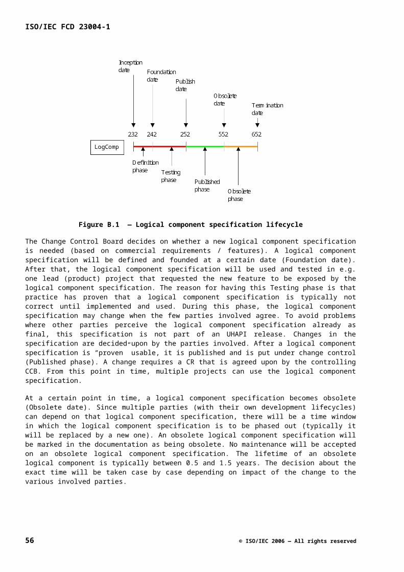
action change type
removing a logical component specification announced change
Rationale:
Adding a logical component specification is allowed, since it does not affect the clients of the platform. In addition, the servers are not obliged to provide an implementation for it.
Removing a logical component specification is only allowed when the termination date of a logical component is reached. This way all parties can anticipate the removal. Usually, either:
the functionality provided by this logical component specification is not required anymore, or
the functionality is now also provided by one or more other logical component specifications.
When a new logical component specification is introduced as replacement of an existing one, the server may decide to support the new one, or the old one, or both. This decision should be based on the need of the clients of that server.
C.5 Evolution of a Specification
This clause describes how the various evolution steps should be handled in a specification document. A number of scenarios are described in the following sub clauses. For certain evolution steps several scenarios must be considered together, e.g. replacing an old interface with a new interface requires adding a new interface and making an existing interface obsolete.
C.5.1 Creating a Variant Logical Component Specification
Creating a logical component specification as variant of an existing specification is almost similar to creating a logical component specification from scratch. In the change history, it should be mentioned on which logical component specification the new specification is based. The version number should re-start (not continuing where the previous specification left off).
C.5.2 Making a Logical Component Specification Obsolete
When a logical component specification has become obsolete, this is marked in the title of the API Specification clause by adding ‘(Obsolete)’ to it. This title is repeated in the headers throughout the document. The actual termination data is not listed in the document (to avoid different versions of the document as a result of a shifting termination date). A list of the actual termination dates for obsolete logical component specifications is kept in a separate document.
C.5.3 Adding an Interface Instance and Specification
Adding an interface to a logical component specification affects amongst others sub-clause 3 and sub-clause 5 of a logical component specification. In sub-clause 3, a new interface instance is added to one of the roles, and in sub-clause 5, the specification of the interface must be given. In C.4.3 it is already described that a new interface based on interface IName can have INameEx or IName2.
A particular case that needs to be considered is the introduction of an interface instance in C.4 that has to become mandatory. In the ‘Interface-Role Model’ figure, the interface must be indicated as optional. In the ‘Provided Interfaces’ table of the ‘Diversity’ sub clause, the interface must also be indicated as optional, with a footnote that this interface is to become mandatory. In case of replacing an old interface with a new interface,
© ISO/IEC 2006 — All rights reserved 57
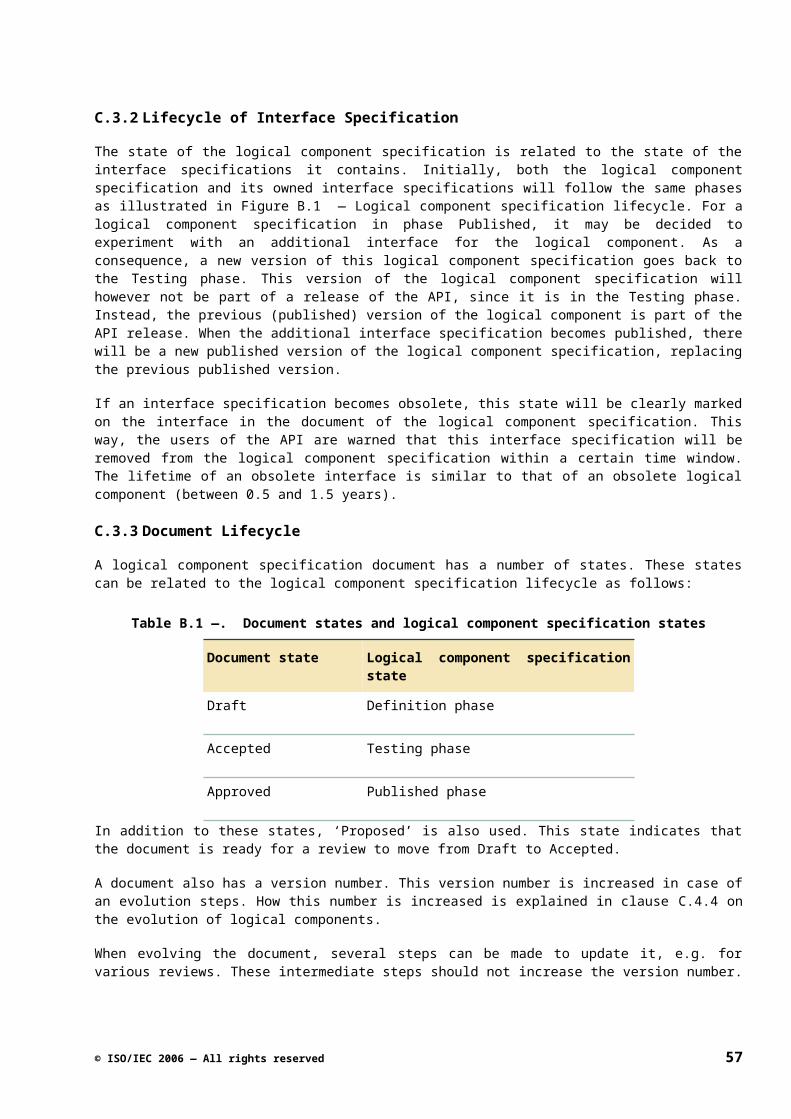
ISO/IEC FCD 23004-1
this footnote can also state that the change from optional to mandatory is linked to the termination of the old interface. Also, the ‘Constraints’ part of the ‘Diversity’ sub clause must state that a user must either use the old interface or the new interface, and not both interfaces at the same time.
C.5.4 Making an Interface Instance and Specification Obsolete
Making an interface instance and specification obsolete affects sub-clause 3 and 5 of the specification clause. In sub-clause 3, ‘(obsolete)’ has to be added in the ‘Interface-Role Model’ figure and in the ‘Provided Interfaces’ table of the ‘Diversity’ sub clause. The actual termination date is listed in a separate document. In case the obsolete interface is being replaced by a new interface, the ‘Constraints’ part of the ‘Diversity’ sub-clause must state that a user must either use the old interface or the new interface (not both).
In sub-clause 5, the interface must be marked as Obsolete. This is done by adding ‘(Obsolete)’ to the sub-clause heading of the interface specification. This will then also return in the headers on the pages of that interface.
When the termination date is reached, all text related to the interface must be removed, and the ‘Interface-Role Model’ figure must be updated.
C.5.5 Adding a Type Specification
When adding a type specification, usually also an interface specification is added. In sub-clause 2, the new type can be specified in a new sub clause. No specific things need to be done, except when adding a new enumeration type that is a modification of an existing enumeration type.
As already explained in C.4.3, there is that problem that modes contained in the old and new type will be defined twice, since there is no scoping on the modes of an enumeration type. In this case, the new enumeration type has to be specified as it should be, and the old enumeration type must be specified based on this new type. This can mean that the old enumeration type now contains additional modes. In a comment it should be added that these modes are not allowed for the old type.
C.5.6 Making a Type Specification Obsolete
When making a type specification obsolete, ‘(Obsolete)’ must added after the name of the type in the sub clause heading. The termination date is kept in a separate document.
When the termination date is reached, all text related to the type must be removed.
C.5.7 Adding and Removing a Constant
Adding and removing a constant is similar to adding and removing a type specification.
C.5.8 Changing the Model
When evolving an interface, it may be needed to make small updates to the model of the logical component (for larger changes, a new variant of the logical component must be created). Elements related to this model can be found in ‘Model Types & Constants’ of sub-clause 2, and in sub-clauses 3 and 4. Changes here should be handled in a pragmatic way. For example, when an attribute of a role changes because of the evolution of an interface, then not a new role with a new name must be introduced. Instead, a construction like #ifdef can be used to differentiate between the situation for the old interface and the situation for the new interface. This is illustrated below.
role Layer { ...
#ifdef uhIVmixLayer
58 © ISO/IEC 2006 — All rights reserved
const PanoramaScaleRange panoramaMidScaleRange;#endif
#ifdef uhIVmixLayer2 const PanoramaMidScaleRatioRange panoramaMidScaleRatioRange;
#endif
...}
When the obsolete interface (in this example uhIVmixLayer) is removed from the specification document at the termination date, these #ifdef constructions also have to be removed.
© ISO/IEC 2006 — All rights reserved 59
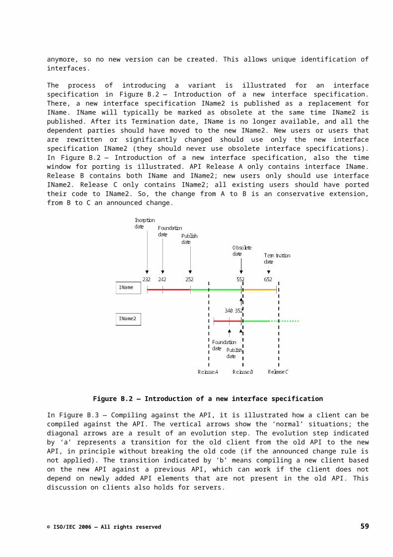
ISO/IEC FCD 23004-1
Annex D(informative)
Naming Conventions
D.1 Introduction
D.1.1 Summary
This document gives an overview of the naming conventions used within M3W interface suite specifications. These naming conventions will help to ensure consistency with respect to naming.
Please note that:
This document describes the naming conventions for the interface suite specifications and not the “language” used for implementation.
This document does not describe explicit naming conventions that result from interface evolution rules. For that information, the reader is referred to C.5.
D.2 General Naming Conventions
This clause introduces the general naming conventions used in interface suites. D.3 provides more detailed information with respect to naming based on the information in this clause.
D.2.1 Basic name construction
Names should be descriptive and will consist of one but most likely more concatenated words. The language used should be US-English. The characters that may be used within names are a..z, A..Z and 0..9. Underscores are never to be used in names, except for special purposes as explicitly indicated within the remainder of this document.
If a name contains multiple words, each subsequent word should start with an uppercase character to improve readability. Subsequent uppercase characters in a name are not allowed (i.e. MPEG should be Mpeg when used in a name). There are two exceptions to this rule:
72) Interfaces names always start with an uppercase “I” followed by the rest of the name starting with an uppercase character.
73) Names for error code constants are entirely in uppercase using underscores as separators between words.
Names representing parameters of a function, members of a structure or attributes of a role should always start with a lowercase character. Names of roles and names of interface functions should always start with an uppercase character.
A name should be descriptive, should be as short as possible (without becoming meaningless) and needs to be unique within its namespace. Annex K gives an overview of abbreviations that should be used to abbreviate words within names when needed.
60 © ISO/IEC 2006 — All rights reserved
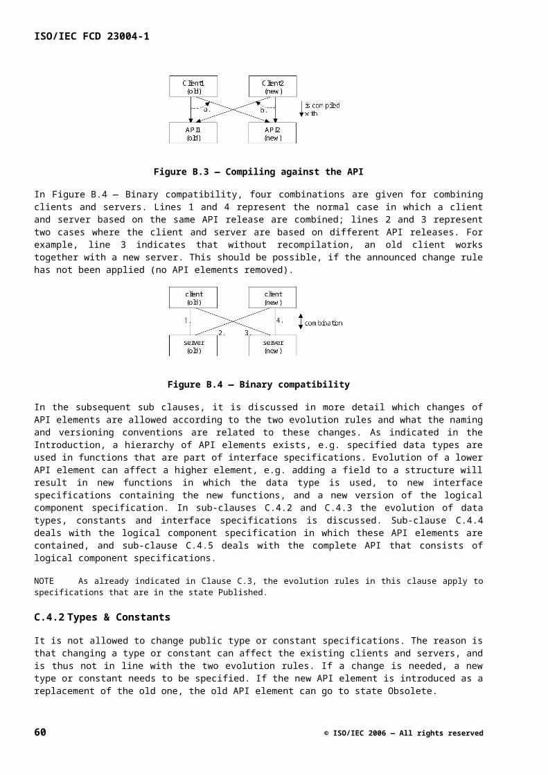
D.2.2 Usage of Pre- and Postfixes
With the exception of basic types, M3W defines its own private name space by prefixing all names of externally visible types it defines with a prefix. This prefix indicates the defining scope of the type and separates types defined by a party from those defined by others.
Basic types used within M3W are considered to have a wider scope and as such are not prefixed with and use commonly used names and conventions. Integer types indicate the size of the type and whether they are signed or unsigned (i.e. Int8, Int16, Int32, UInt8, UInt16, UInt32).
Names that are defined for modelling purposes only (i.e. role names, role attribute names, model types and constants) are not externally visible and should not be prefixed.
Names of externally visible types reflect the scope in which they are defined. Names of types defined within an interface suite should contain the abbreviated name of the interface suite unless the type is common to multiple interface suites and as such has a wider scope such as basic types and global types. See the examples given in the Table C.1. — Example of naming based on scope.
Table C.1. — Example of naming based on scope.
Defining suite Example Scope
Basic typesUInt32 M3W
Core framework typesrcIService M3W core component framework
UHAPI types uhColor_t Multiple UHAPI interface suites
Video Mixing uhVmix_Layer_t UHAPI Video Mixing interface suite, short name “Vmix”
To improve readability the following conventions are to be used:
Names representing interfaces are prefixed with “I”
Names representing types have the postfix “_t”.
General post fixing scheme for types:
<TypeName>_t
Names representing type tags have are prefixed with an underscore:
General prefixing scheme for type tags:
<TypeName>_t
Names representing pointer types and names that are pointers have a prefix starting with “p” or “pp” in case of an output parameter returning an interface pointer. If required, an indirection or dereferencing operator “*” should be placed in front of the prefix.
General prefixing scheme for types and names representing pointers:
*p<TypeName>_t
© ISO/IEC 2006 — All rights reserved 61
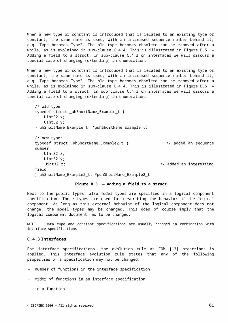
ISO/IEC FCD 23004-1
p<ParameterName>
*p<InterfaceName>
**pp<InterfaceName>
D.3 Detailed Naming Conventions
This clause provides detailed information with respect to naming based on the general naming conventions described in D.2.
D.3.1 Naming Error Codes
The names of error codes are in uppercase only using underscores as separators between words. All names of error codes should start with the prefix “<SCOPE_PREFIX>_ERR” followed by the abbreviated name of the defining interface suite, followed by the rest of the name that should clearly describe the cause of the error. The part of the name describing the cause of the error should use the same vocabulary as the interface reporting the error
General naming scheme for an error code:
<SCOPE_PREFIX>_ERR_<ABBREVIATED_SUITE_NAME>_<ERROR_CAUSE>
D.3.2 Naming Types and Constants
The names of externally visible types and constants of an interface suite consist of two main parts using an underscore as separation. The first part of the name represents the defining scope. The second part of the name should start with an uppercase character, be descriptive and clearly reflect what the type or constant is about. For example, if a type represents a set of values the descriptive part of the name should end with “Set” in order to explicitly indicate that the type represents a set of values.
General naming scheme for an externally visible type:
<Prefix><AbbreviatedSuiteName>_<TypeName>_t
General naming scheme for an externally visible constant:
<Prefix><AbbreviatedSuiteName>_<ConstantName>
If a type or constant is only used for modeling purposes, the first part of the name including the underscore should be omitted in order to explicitly indicate that the type or constant is not externally visible.
Names used for members of a structure should not repeat the name of the structure they belong to as part of their name. Names used for enumerated values of an enumerated type do not have to repeat the name of the enumerated type in their names unless required to do so in order to be unique.
Names of enumerated values used to subscribe for event notifications should clearly indicate the nature of the event they represent (i.e. by ending with a past sense verb). Some examples:
If the event indicates a change, the name of the event should end with “Changed”. Example: “SubscriptionChanged”.
If the event indicates a detection, the name of the event should end with “Detected”. Example: “DataRateDetected”.
62 © ISO/IEC 2006 — All rights reserved
If the event indicates the arrival of data, the name of the event should end with “Arrived”. Example: “DataArrived”.
A name of a constant or enumerated value used to indicate that something could not be determined (i.e. by a detection process) should end with “Unknown”. The name of a constant or enumerated value representing a value used to indicate that something is temporarily unavailable should end with “Invalid”.
D.3.3 Naming Interface Suites and Logical Components
The name of an UHAPI interface suite specification should describe what the suite is about and whenever possible describe this as an action (i.e. Video Mixing, Tuning, RF Amplification, Scan Rate Conversion). The name of a logical component of an interface suite should be based on the name of the interface suite and preferably be a noun that describes the entity that performs the action.
Table C.2. — Example Interface Suite and Logical Component names.
Interface Suite name Logical Component name
Video MixingVideo Mixer
Tuning Tuner
Interface suite and logical component names are only used within the specifications and do not end up in code used for implementation. To reference an interface suite in the code used for implementation, an abbreviated name for the interface suite is defined that should start with an uppercase character (i.e. Vmix for the Video Mixing interface suite).
D.3.4 Naming Roles
The name of a role should be a noun starting with an uppercase character. The name of the role needs to be descriptive and clearly indicate what the role is about. A name for a role representing the client of an interface suite (client role) should end with “Client”. The name of a client role should be based on the name of the interface suite and not on a role of the logical component. For example: the name of the client role of the Video Mixing interface should be “VideoMixingClient” and not “VideoMixerClient”.
D.3.5 Naming Interfaces
Interface names are prefixed and start with a capital “I” followed by the rest of the name of the interface starting with an uppercase character. This is an exception to the general rule, not allowing subsequent uppercase characters in a name. Following the capital “I” an interface name should start with the abbreviated name of the interface suite defining the interface followed by the descriptive part of the name that should clearly indicate the aspect the interface is about. In cases where this would only add redundant information, the redundant part of the name should be omitted (i.e. uhIVmix should be used instead of uhIVmixMixer).
General naming scheme for an interface:
uhI<AbbreviatedSuiteName><DescriptiveName>
All names for notification interfaces should end with “Ntf”. If a control interface is related to a single notification interface, the name of the notification interface should repeat the name of the control interface extended with
© ISO/IEC 2006 — All rights reserved 63
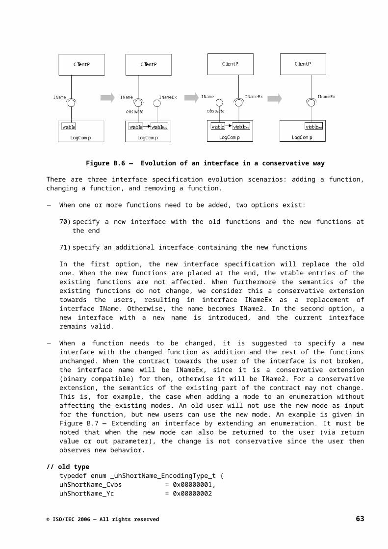
ISO/IEC FCD 23004-1
“Ntf” (see Table C.3.). In some exceptional cases, a control interface may be related to multiple notification interfaces. In such a case, the name of a notification interface needs to be extended (after repeating the name of the control interface) with an additional word that clearly indicates the discriminating aspect of that particular notification interface with respect to the others.
Table C.3. — Example names of control and notification interface pairs.
Control interface name Notification interface name
uhIVmix uhIVmixNtf
uhIVmixLayer uhIVmixLayerNtf
uhIVmixVidLayer uhIVmixVidLayerNtf
uhIVmixGfxLayer uhIVmixGfxLayerNtf
D.3.6 Naming Interface Functions
Names of interface functions and their parameters should have no prefix and the abbreviated suite name since they are already scoped by the interface they belong to. Interface function names should always start with an uppercase character. Names of parameters of an interface function should always start with a lowercase character. Parameter names should be descriptive and clearly indicate what they represent. Names of parameters representing a pointer should start with a “p”.
D.3.6.1 Naming Control Functions
Function names of control interfaces are preferably verbs and should not contain redundant information already provided by the name of the interface itself. For instance: the function of the uhICti interface to enable the CTI (Color Transient Improvement) feature is called Enable instead of EnableCti (unless this results in ambiguity). The name of an interface function should clearly reflect what the interface is about. For instance: interface function names for setting and getting the value of an attribute should start with “Set” and “Get” respectively and clearly and uniquely indicate the attribute concerned when not already obvious from the name of the interface.
Annex H describes patterns for Get/Set-functions and related functions and the naming conventions to be used for these functions.
D.3.6.2 Naming Notification Functions
The function names defined by a notification interface should always start with “On” followed by the actual name of the event repeating the name of the enumerated value used to subscribe for the notification of the event (see Table C.4.). The name of the function should clearly indicate the nature of the event it represents (see also the naming conventions for enumerations used to subscribe for the notification of events in paragraph 2.2).
General naming scheme for a Notification function:
On<EnumeratedValueName> (Example: “OnSubscriptionChanged”).
64 © ISO/IEC 2006 — All rights reserved
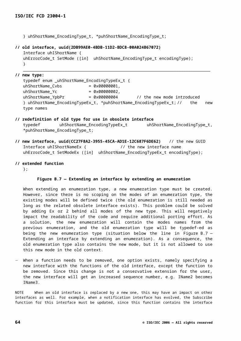
Table C.4. — Example notification function names repeating enumerated value names.
Enamerated value name Notification function name
SubscriptionChanged OnSubscriptionChanged
DataRateDetected OnDataRateDetected
DataArrived OnDataArrived
D.3.7 Naming Interface Function Macros
Interfaces are expected to be implemented using C or C++. To implement interfaces when using the C language, it is convenient to use preprocessor macros for interface functions. This clause describes naming conventions for these macros to improve portability of implementations.
For readability, interface function macros should look like normal C functions. To achieve this and to guarantee the uniqueness of the macro names they are synthesized from the interface name and the function name separated by an underscore.
Since names need to be unique within the global name space, it helps to keep their maximum length limited to 31 characters. Please note that the macro length (since it is the concatenation of the interface and function name) restricts the length of the actual interface and its function names.
General naming scheme for an interface function macro:
<InterfaceName>_<FunctionName>
The parameters of the interface function macro should use the same names and be in the same order as the parameters of the actual interface function represented by the macro.
uhIVmixLayer->GetBgColor( pBgColor );uhIVmixLayer_GetBgColor( intf, pBgColor );
The first parameter of the interface macro should be added as the first parameter to every interface function macro. This parameter represents a pointer to a (C++ Vtable like) function table representing the actual interface.
NOTE since every interface inherits from rcIUnknown the function table and the interface function macros for every interface must include the QueryInterface, AddRef and Release as it first three functions in the given order.
uhIVmixLayer_QueryInterface( intf, iid, ppUnk );uhIVmixLayer_AddRef( intf );uhIVmixLayer_Release( intf );
© ISO/IEC 2006 — All rights reserved 65
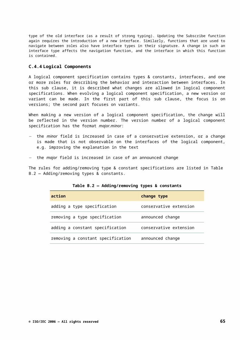
ISO/IEC FCD 23004-1
66 © ISO/IEC 2006 — All rights reserved
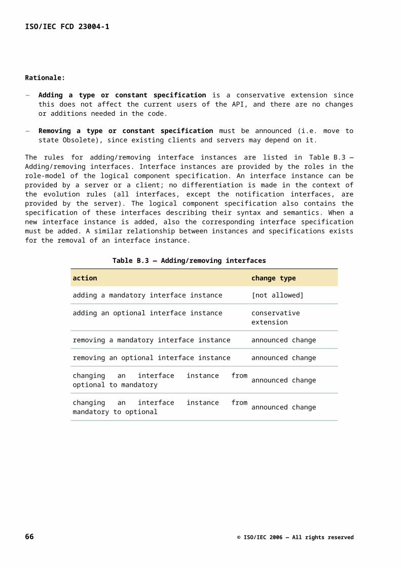
Annex E(informative)
Constraints on Execution Architecture
E.1 Introduction
E.1.1 Summary
This clause describes the specification of the framework execution architecture of the API. The idea is to specify (part of) the execution architecture for the API independent of a particular API instance, that is, to specify it on the API framework level.
The aim of this clause is to guide those people who are involved in the definition of the API and to capture the rationale that led to the decisions taken.
E.2 Constraints
This clause describes the decisions that were taken about the execution architecture.
E.2.1 Middleware requirements
In order to specify an execution architecture for the API, it is imperative to know what the various middleware stacks require. These requirements are found to vary wildly. For example, some middleware requires only single-threaded access to the complete streaming API. On the other end of the spectrum, other stacks require complete thread-safe access to the complete streaming API.
Based on these observations it was decided not to study the requirements of all middleware stacks in detail, but to provide an execution architecture solution that can handle the complete range of middleware requirements. In some cases, an adaptation layer needs to solve mismatches.
E.2.2 Thread-safe versus single-threaded
There are several "levels" on which one can specify thread-safeness or single-threadedness: platform, logical component, role, interface, and function. The scope of the threading model can be a single instance or a class (that is the scope is all instances of the class).
When deciding whether an entity as mentioned above should be thread-safe or single-threaded, there are two competing forces. One is ease of implementation and ease of testing, which asks for the interface to be single-threaded. The other is ease of use, which asks for the interface to be thread-safe.
The API tries to find the right balance between the two. Note that the client can often solve synchronization problems cheaper and better above the API because the client has more knowledge about its exact synchronization requirements than the API implementation. Performance is also an issue in this context, although sometimes single-threadedness is better for performance (no synchronization overhead) and sometimes thread-safeness (allow concurrent access). These considerations result in the following guideline:
© ISO/IEC 2006 — All rights reserved 67
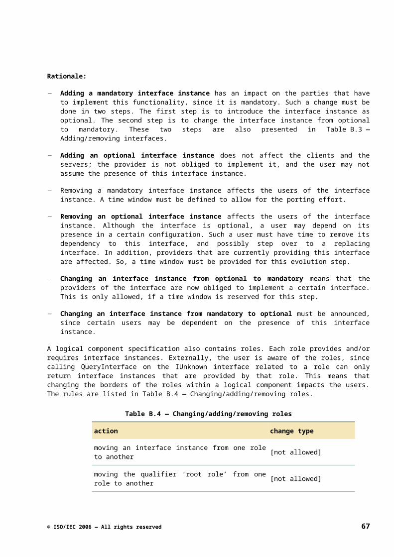
ISO/IEC FCD 23004-1
API design guideline:
A logical component instance is single-threaded. This means that the overall number of threads that may concurrently execute methods of all public interfaces of a logical component instance is at most one.
This guideline is the default rule for a logical component. With good reasons, one can deviate from this rule.
In general, it should be relatively easy to implement a logical component instance in such a way that each instance is single-threaded, while different instances may be accessed concurrently. One reason that it is relatively easy is that component instances are expected to share only little state and resources (except possibly when they share a single physical component).
At the same time, the guideline does not couple different parts of client code too much threading wise. If it were chosen that a greater domain than a single logical component instance was single-threaded, then the likelihood that different parts of client code - which are expected to typically control disjunct sets of logical components - need to synchronize with each other increases significantly. This requirement for the client software to synchronize is not desired in general.
Some streaming API implementations require the client to use a specific thread (or synchronize with that thread) to do down calls. This is because the API implementation internally only uses a single thread and the client must use the same thread. In the M3W context (where the API implementation and its clients are often developed by different organizations) this execution architecture coupling of the API implementation and client is undesired, and therefore M3W will have no such restrictions.
E.2.3 What if the middleware requires thread-safe behavior?
If the middleware running on top of the API requires thread-safe behavior, then the adaptation layer for the middleware must use a synchronization mechanism to comply with the single-threaded behavior of the API. For instance, the adaptation layer can use the monitor mechanism (typically one monitor per single-threaded domain) for this. It is expected that this will not cause major problems, as such adaptation layers have been made before.
E.2.4 "Get"-functions are thread-safe
Making "Get"-functions thread-safe is relatively easy. The implementation can just use small critical sections to protect the underlying data. A disable/enable interrupts implementation or a disable/enable preemption implementation (less dangerous on data not shared by ISRs) are also cheap. At the same time thread-safe "Get"-functions are attractive to a client, because typically one part of the client controls a specific functionality, while multiple parts of the client may be interested in the state of that functionality. This leads to the following guideline, which is an exception to the guideline that the logical component instance is single-threaded:
API design guideline:
"Get"-functions are thread-safe, irrespective of whether the interface of which it is part is thread-safe.
Note that it is explicitly not proposed to make "Set"-functions thread-safe, even though the changing of the attribute must be thread-safe because of the above-mentioned rule. The reason for this is that "Set"-functions typically do more than just changing an attribute, they typically also do actions that effectuate the new value of the attribute. It may be more expensive or less trivial to make those actions thread-safe as well. It also does not make sense to invoke a set function with multiple uncontrolled threads since the semantics would be undefined anyway (race condition).
68 © ISO/IEC 2006 — All rights reserved
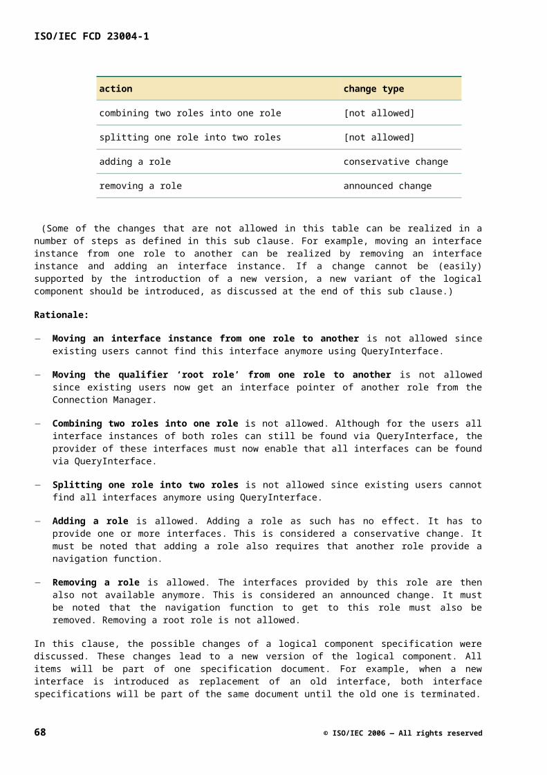
E.2.5 Impact of a multi-process context
Operating systems like Linux or WinCE support processes with their own threads and address space. This as opposed to for example pSOS that has no concept of processes. A multi-process context does not pose fundamental new requirements to the execution architecture of the API.
If the API implementation is used in a multi process context, then it can be put in a shared library (DLL), which is mapped into the address spaces of all processes that require it. There is of course an impact for the memory architecture. Buffers passing the API boundary must be mapped in a part of the address space that is common (known) to the client and the API implementation. The memory architecture is out of scope for this document though.
Although there is no fundamental new requirement for the execution architecture of the API, there is a practical one for the clients in the different processes. Synchronization between threads in different processes is more difficult than synchronization between threads in a single process, because the synchronization primitives like semaphores have to cross a process boundary. As a consequence, the execution architecture of the API should ideally be such that no synchronization between different client processes is needed. In particular, there is an example (Microsoft's TV software running on WinCE) where broadcast reception control and graphics are in different processes. The API needs thus be such that broadcast reception control and graphics are not related with respect to threading. This is easy to do except possibly where graphics and broadcast reception control come together (i.e., in the video mixer). The video mixer is however likely to have a non-default threading model to cope with the threading requirements. Concluding, the multi-process issue does not have impact on the chosen execution architecture of the API.
E.2.6 Notification functions and down calls
Allowing a client implementation of a notification function to wait for a synchronization primitive may result in deadlock and priority inversion problems. Different client notification functions can be called on a shared platform thread. This results in the following guideline:
API design guideline:
Implementations of notification functions may never wait for synchronization primitives that can cause scheduling (blocking) and notification functions must return in a defined and bound time. It should be a goal for the client to have notification functions return as soon as possible.
Because typically API platform calls are not defined to be non-blocking, no calls to the API functions may be done during a notification call. If needed though, the client has to decouple the event and do the processing on a thread of its own.
It would have been possible to specify on the API that all the notification calls are always decoupled by the platform. This would result in too many task switches because some notifications can be handled directly on the thread of the platform implementation. It is only the client that knows what will be done in the notification function and the decision to decouple is thus left up to the client.
The “Get”- functions, to just get an attribute of the platform, are very simple to make thread-safe. They typically only need a very short critical section that can be implemented by e.g. disabling the interrupts for a short moment. This does not induce the problems described above. Allowing these down calls will reduce the number of task switches of the system.
The arguments in the paragraphs above result in the following guideline:
API design guideline:
From within a notification function no down call to an API function is allowed, either directly or indirectly, except to thread-safe "Get"-functions.
© ISO/IEC 2006 — All rights reserved 69
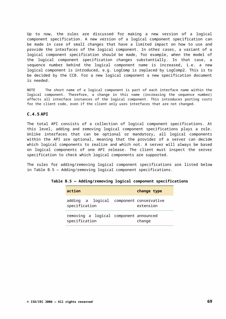
ISO/IEC FCD 23004-1
In special cases, the API may deviate from the rule mentioned above. Typically, this is because the notification function is intended to trigger a very specific action that is timing sensitive, from the client. For each such deviation, it shall be specified explicitly that it is a deviation from the general rule. Also the documentation must explicitly state which API functions are allowed to be called from within notification functions. These API functions may then be called from within any notification function.
Note that in some situations that require direct timing sensitive actions there is an alternative to deviating from the above rule. We did not choose this alternative. This alternative is to use output parameters of the notification function to indicate the actions that must be taken. For instance, if a buffer must sometimes be freed, then the notification function can have an output parameter freeBuffer. We did not choose this alternative because notification functions with no output parameters or return values have a great benefit. Such notifications can be handled completely asynchronously from the code that generated them. Having exceptions to this benefit is considered less attractive than having exceptions to the above-mentioned rule.
Although the rule forbids down calls (except the “get”-functions) in a notification function, the client often wants to perform a down call to control the platform triggered by a call to a notification function. In the notification function, the client can however send a message to one of its own threads, and perform the down call on that thread.
From a performance viewpoint, it is essential to reduce the number of task switches and inter processor communications as much as possible. This results in the following guideline:
API design guideline:
Design a notification function such that it provides all the information a client typically needs about the event as parameters of the function.
For example, having an OnVolumeChanged() without any parameter requires the client to get the new volume setting itself (a down call). It is better to add a parameter newVolume to the notification function.
This also solves a race condition in case the client is notified of a change and calls the Get function on the changed attribute. It is possible that the value that the Get function returns is a newer one than the value that triggered the notification.
E.2.7 Serialization of callbacks
Specifying rules for how the implementation must perform callbacks threads-wise helps simplifying client code. Without any rules, a client must implement all notification interfaces thread-safe, which may be needlessly complex or expensive. Therefore, the API implementation must guarantee the following:
Allowed client assumption:
For each individual subscription (that is, a subscriber, cookie pair), the API guarantees that all notifications will be serialized, that is the next notification function will not be called before the previous one has returned.
Note that this guarantee does not apply across different subscriptions, even not to different subscriptions of the same subscriber that uses different cookies. The reason for this is that the client does not benefit much from it probably because it is likely to use a different set of variables for each individual subscription. On the other hand, a stricter guarantee would reduce API implementation freedom.
It is also important to specify something about the order of events:
Allowed client assumption:
For each individual subscription, the order of notifications of events is the same as the order in which the events are detected.
70 © ISO/IEC 2006 — All rights reserved
Note that this (minimum) guarantee must only be given as far as the client can deduct the detected order of events (related events). Enlarging the scope of this guarantee across different interfaces (or different instances of interfaces) is very difficult. This will always depend on the actual scheduling of the different threads (even in the client code). If such a guarantee is essential, a different solution must be used (e.g. the use of time stamps).
Note also that this guarantee excludes “prioritized” events in a single notification interface.
An API client should take notice that they cannot draw conclusions about the order of notifications to different subscribers based on the order of subscriptions.
E.2.8 Asynchronous callbacks
Allowing a server implementation of the API to perform callbacks on the load of the caller of an API function is in principle dangerous. It can easily result in deadlocks if the client code waits on synchronization primitives in the notification functions. Although good client programming can avoid deadlocks, it is better to prevent them in the first place. The implementation costs of asynchronous (decoupled) callbacks are minimal. Therefore, it is advised for the implementation to adhere to the following guideline.
Guideline:
Do not perform callbacks on the load of the client thread.
NOTE this should become a rule if we allow a client to wait on synchronization primitives.
Furthermore, if the notification in question is ever executed autonomously (e.g. as a result of an interrupt) there needs to be a synchronization between the platform thread doing that notification and the client thread. It is then probably just as easy not to use the client thread for the notification.
A platform can impose limitations on what may be done on the load of an interrupt service routine. The client can be sure that such limitations do not apply to callbacks.
Allowed client assumption:
Callbacks will not be performed on the load of an interrupt service routine.
There is no guarantee that always the same thread performs the callbacks for a particular subscription (that is, subscriber, cookie pair):
Implementation freedom:
The API implementation can use a different thread for each individual callback.
On the API framework level, we explicitly do not want to prescribe how many threads to use for callbacks, or even which callbacks share the same callback thread(s). Choices for this depend too much on the API instance. The API instance document though may specify these issues.
© ISO/IEC 2006 — All rights reserved 71
ISO/IEC FCD 23004-1
Annex F(informative)
Error Handling
F.1Introduction
F.1.1 Summary
An error can be defined as a condition that, if not handled, can cause a system to crash or malfunction. Many errors can be avoided by using appropriate development and verification techniques, but it is a fact-of-life that most systems contain errors. When these errors manifest themselves at execution time, they should somehow be handled to avoid the system to crash or malfunction.
This clause describes the kind of errors are visible on the M3W API. The M3W API supports different domains/products that use different error handling strategies. This clause lists the M3W API error handling strategy.
F.2Error Handling Strategy
F.2.1 Error Handling Goals
Returning errors has one or more of the following goals:
G1. Indicate that a postcondition of a certain method is not met. Otherwise, the client of the server would make WRONG ASSUMPTIONS.
G2. Indicate WHAT went wrong in order to help the caller to RECOVER from the situation.
G3. Communicate an exceptional functional result. This is in fact part of the functional control interface (e.g. tan(Pi/2) results NotANumber).
When debugging a client or a server, returning error values is not the best tool.
While defining error codes, one obviously has to know which goal(s) one is trying to achieve. An example of the wrong usage according to these goals that is often found is returning a detailed implementation error code on an interface (e.g. returning I2C write error on SetVolume). This by no means complies with G3 (it is not a functional result of SetVolume). It does not comply with G2; a volume control client (e.g. UI) cannot recover from an I2C write problem. So, apparently it is there for G1 (or for debugging purposes). For that purpose, just returning a global "error" would have been enough and it will result in a more robust interface (less specific). An exceptional situation should be handled as an exceptional case (e.g. exception handler). Exceptional cases typically are not and cannot be handled by the general functional client. The exception handler can be used for reporting that the postcondition is not met. This will be discussed in sub-clause F.2.4.
F.2.2 Error Value Requirements
From the goals in the previous sub clause the following requirements can be deducted:
R1. The error value returned shall be such that the client of the interface is capable of handling the error condition. For example, a “volume controller” cannot handle an I2C error but “maximum volume reached” can be considered a functional return value of an “increase volume” function.
72 © ISO/IEC 2006 — All rights reserved
Thus, the following induced requirements hold:
R2. The error value on an interface should indicate as precisely as possible what the problem is.
However,
R3. The error value on an interface should be in the "vocabulary" of the interface. Again, returning I2C write error is not part of the vocabulary of the volume controller, it only knows about volume up or down, etc., it does not understand I2C. It even does not know that I2C is used in the implementation, as the interface should be platform independent.
Furthermore,
R4. The error should not have been predictable. If it were predictable, it should have been caught by means of a different scheme (e.g. assert). Furthermore, the client will never have code to anticipate on something that could have been predicted. Note that sometimes this is considered acceptable because of programming convenience. For example, reading a file may result in EOF being returned although one could have known the size of the file.
R5. It should be possible to log non-functional errors. This makes it possible (for e.g. service-engineers) to determine what went wrong.
Error values for M3W API shall meet the requirements above.
F.2.3 Error Categories
In general, the following categories of errors can be identified:
E1. Programming errors
Programming errors are trapped with assertions during the debug phase. They are typically not checked in the retail build. No clean up is attempted in the case of programming errors. Program execution is halted immediately. In the retail build, programming errors are likely to result in undefined behavior, as the error conditions are simply not checked in this case. Programming errors fall into two basic categories:
Caller errors are a result of not complying with preconditions of the method being called. Examples are supplying a wrong input parameter or not complying with the proper calling sequence. These can (and should) be checked with asserts at debug time. Strong typing helps to avoid type problems.
Callee errors can have several causes:
Out of bounds, divide by 0, etc. These can be checked with a tool e.g. BoundsChecker at debug time.
Wrong resource assumption. For example, the amount of resources available/left. These can be checked with asserts at debug time.
Wrong resource usage. For example, not releasing memory, a semaphore, any other resource. These can be checked with a tool e.g. BoundsChecker at debug time. Acquiring a wrong resource type for a particular service. This might be countered (to some extend) with strong typing.
Other errors resulting in the postcondition not being met. This is to be found by means of proper test applications.
E2. Functional errors
© ISO/IEC 2006 — All rights reserved 73
ISO/IEC FCD 23004-1
These errors are supposed to be handled by the client. The server component reporting the error is in a normal state and can continue its task as specified. An example is an “increase volume” function that returns a “maximum volume reached” error code. Errors of this type are part of the “protocol” associated with an interface and specified within the interface. Failing to handle such an error in the appropriate way is considered a programming error.
E3. Exceptional errors
These are errors that are detected by a server component but that are explicitly not resolved by that component (e.g. because of too much effort, too high cost, too low benefit). Fatal errors are one group of exceptional errors. The fundamental difference with a functional error is that the server component is not in a normal state anymore. In order to handle these fatal errors the platform provides special functionality, referred to as the fatal error handler. Fatal errors that occur in the platform are reported by the fatal error handler to the client that typically aborts normal program execution. The other group of exceptional errors consists of non-fatal errors. These are also system-wide errors, but the system is able to continue after their occurrence. Non-fatal errors are also reported via the fatal error handler via a separate interface. Whether an exceptional error is fatal or non-fatal is specified by the platform instance.
F.2.4 Error Handling Mechanisms
For the programming errors, no error handling mechanism is described except for the proposed usage of assertions during development time.
For the other two error categories, there are several mechanisms to inform the client of the occurrence of an error. These mechanisms are:
Return code of a function. Every function defined within M3W (except notification functions) has rcResult_t as return type and returns at least RC_OK. Whenever a functional error is detected during the execution of a function call, the caller is informed via the return code of the function. This return code has to be specified as part of the behavior of the function, since it is part of the functional behavior. An example is given below:
Return values of the function:
Table E.1
Name Description
RC_OK The function call succeeded. All output parameters contain valid values.
UH_ERR_SPDIFIN_NO_CHANNEL_DATA No meta-data present for the specified channel. The content of the output parameters is undefined.
Error notification function of a logical component. Some errors detected by a logical component are not directly related to a function call, however they have a meaning in the domain of the logical component. These errors are usually related to the quality of an audio or video stream. Examples of such errors are: ‘parity error’ or ‘sync lost’. These errors should in principle not occur, but the client of the logical component is able to handle the error, i.e. it tries to recover or goes to a defined state. These are also functional errors. To inform the client of these errors, the logical component defines a notification to which the client can subscribe.
74 © ISO/IEC 2006 — All rights reserved
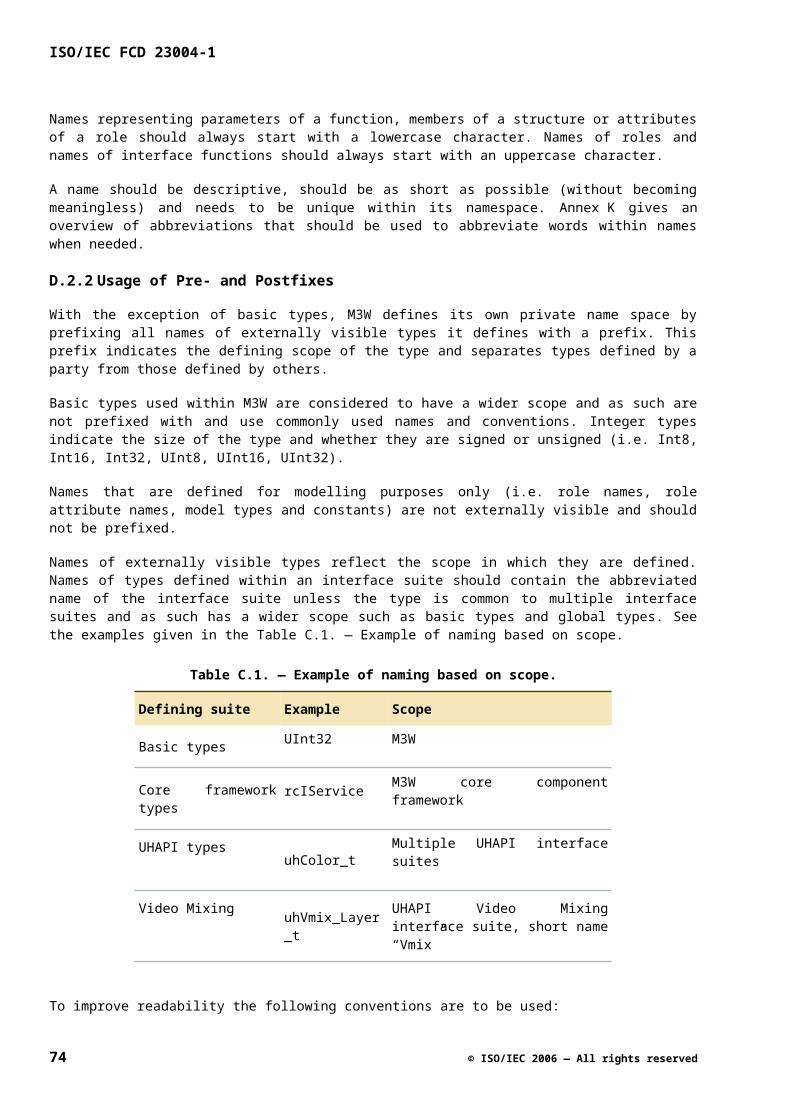
Non-fatal error handler of the platform instance. The platform instance as a whole provides a handler for non-fatal errors. These errors are non-fatal in the sense that the system can continue after their occurrence. It is not useful to notify these errors in the context of a specific logical component because they are of no use to the client of such a logical component. An example of such an error can be exceeding the maximum delay between input and output of the entire system. The reason to notify these events is not directly to impact the functional behavior of the client, but to allow the client to log these events for testing or servicing purposes.
Fatal error handler of the platform instance. The platform instance as a whole provides a handler for fatal errors. All fatal errors must be notified via this handler. A client should install a client handler that is capable of handling a notified fatal error. A fatal error typically leads to bringing the system in a defined state again via a reset (the reset space depends on the system context). These errors must be handled by a client error handler, which determines how the program is actually terminated.
F.2.5 Error Numbering Conventions
F.2.5.1 Functional Errors
Functional errors are defined using a 32-bit error code. The high bit of a functional error code is never set (to indicate the difference with exceptional errors).
One global functional error is defined: RC_OK (0x00000000). In case a functional error has occurred, a value in the range 0x00000001 to 0x7FFFFFFF is returned. The lowest 12 bits are defined by M3W and represent the actual error code, ranging from 0x00000001 to 0x00000FFF. The remaining 19 bits can be used in a platform specific way, e.g. for debugging purposes. When no error has occurred, these 19 bits also have to be zero. This makes the check on RC_OK straightforward. The structure of the functional error code is given in Figure E.1 — Functional error code.
Figure E.1 — Functional error code
F.2.5.2 Exceptional Errors
The errors are indicated by error codes in the range 0x80000000 to 0xFFFFFFFF. These codes are defined in a platform specific way.
Figure E.2 — Exceptional error code
F.3General Interface Rationale
If we would expose all detailed implementation errors on an interface, we would have the following problems:
© ISO/IEC 2006 — All rights reserved 75
ISO/IEC FCD 23004-1
The interface changes every day: since we don't know what the client is going to do with which error, we have to expose all internal errors on the API interface. So, whenever the new implementation interface changes (it can report a new error condition) the actual platform interface has to change to allow for propagation of the errors. Thus, it is not acceptable to have the detailed error conditions on the control API.
Compatibility: if we are going to return error conditions based on the input parameter checking (and the client is going to rely on this), it is no longer allowed to change (enlarge) the possible domain of an interface of the server. Suppose that the client requires an interface to take the square root of positive numbers. If that method would return an error if the client tries to calculate the square root of a negative number, then it is not possible to upgrade the server so that it can also take the square root of complex numbers and bind it to the same client (while in principle it could do the job as it is a true superset). For this reason, specifying on an interface that input parameters will be checked and appropriate error codes are returned is not acceptable. Note however that a certain implementation (platform instance that complies with the interfaces) may check input parameters and clip them in case of problems in order to recover from the problem. Clients should, however, never depend on this.
Footprint: actually checking parameters increases the footprint as the code in the server to check parameters has to be written. Furthermore, the client code that actually checks these parameters has to be written as well, and it is very unlikely that this will be useful code. The error scheme should allow for clean client implementations that do not have to deal with error return codes for every call.
Testing: all the additional code to check parameters has to be tested which makes it more difficult to get a good coverage. The error scheme should allow for clean server implementations that do not have to deal with error return codes for every call.
Lazy Programming
Sometimes it can be very convenient if one could stop a device twice without getting the error: “device already stopped” as a result of the second call. Allowing this, however, will destroy a potential means to catch programming errors. So, this should only be used when it significantly increases programming convenience.
F.4 Context of Errors
The context in which a certain error takes place obviously determines whether or not it should be returned as an error value on an interface. Again, consider the I2C example. Such an error condition should not be returned on the volume control interface, but it can definitely be returned on the I2C communication interface. On the latter interface, it becomes a functional error condition (E2).
76 © ISO/IEC 2006 — All rights reserved
Before Release or After Release
Figure E.3 — Who is going to debug, the integrator or the end customer?
The picture above tries to depict the contradiction in requirements with reference to the handling of errors. The errors of class A are found during development. Obviously, we have to do everything we can to catch as many of them as we can as soon as possible (e.g. assert when the precondition is not met). There is no need for graceful degradation; it is even undesired (it can only hide the problem). After the product has been released, however, this is not that obvious anymore and we still have e.g. 1 % of the errors present in the system. We don't want customers of a complete product to actually debug the product (we want to reduce the field call rate). So in that case, one does want to have graceful degradation if possible (hide the error).
On the other hand, postponing the handling of the error condition (e.g. by ignoring the problem) can obviously result in more severe problems. In that case, it might have been better not to ignore the "small" problem. The message is, that it depends a lot on the context (type of product, etc.) what to do with a certain error condition. So any exception scheme has to allow for local decisions to be made on recovery, abort, or do nothing. The client must be able to determine the granularity of error checking, recovery/handling.
Figure E.4 — Different Stakeholders
© ISO/IEC 2006 — All rights reserved 77
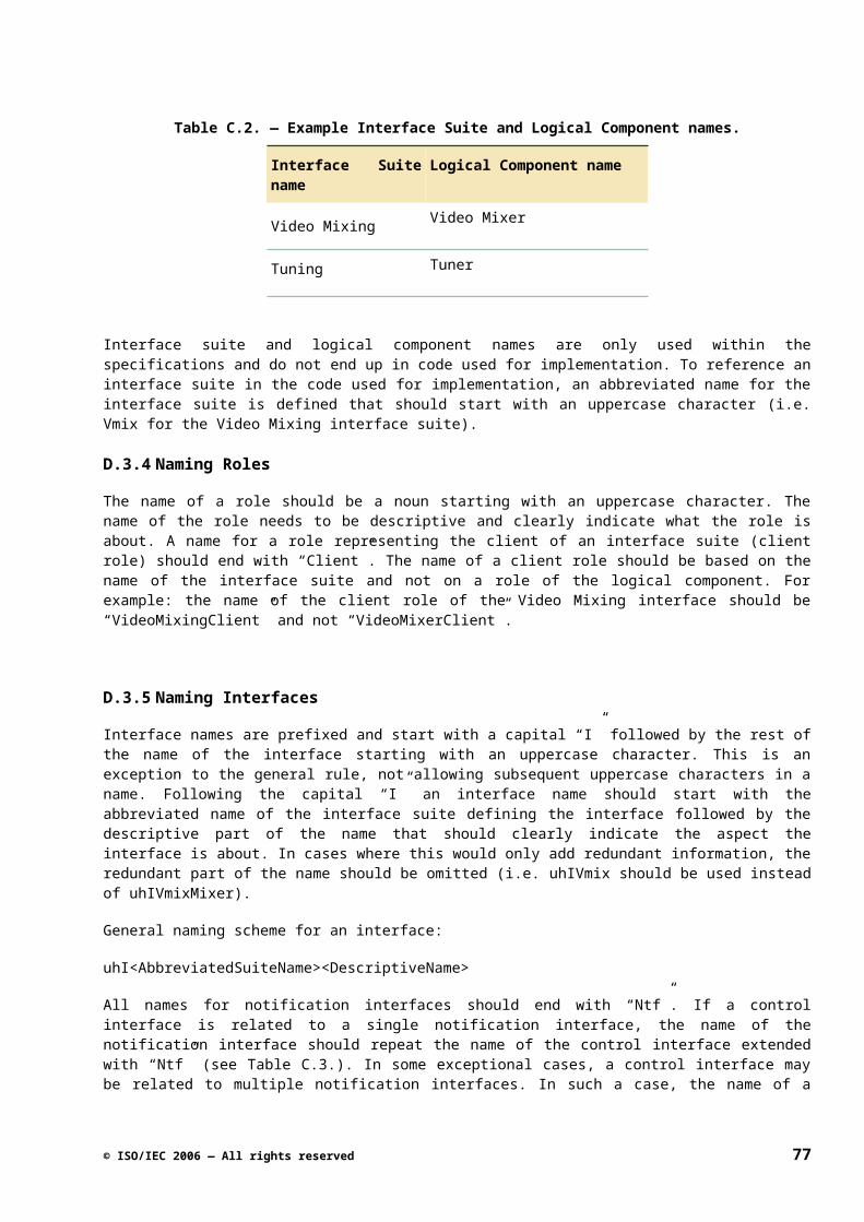
ISO/IEC FCD 23004-1
System Integrator or Application Builder
For the application builder, it is very convenient that the minimum amount of errors is returned and that they can obviously be understood/handled by the application builder. The system integrator, however, wants to find out about any error during testing, and he probably understands every error. Next to this, he wants to minimize the final product field call rate.
Since we are providing a platform, we cannot make too many assumptions about the different clients of the platform or the products that will be built with this platform. This is a very similar situation to operating systems. The safest solution is to provide means to communicate all error codes to the client of the platform.
Are we building the product or a part of the product?
If we are building the entire product (horizontal market/set builder), we can make decisions what to do in a certain fatal error condition within the platform. This allows you to have methods on an API that have no return value at all. This makes the platform very convenient to program. If we are just providing a platform (like in a vertical market), it is often the third party middleware stack that demands to be in control in case of exceptional error conditions. In such a situation, we have to provide means for letting the application decide what to do in case of an exceptional error.
78 © ISO/IEC 2006 — All rights reserved
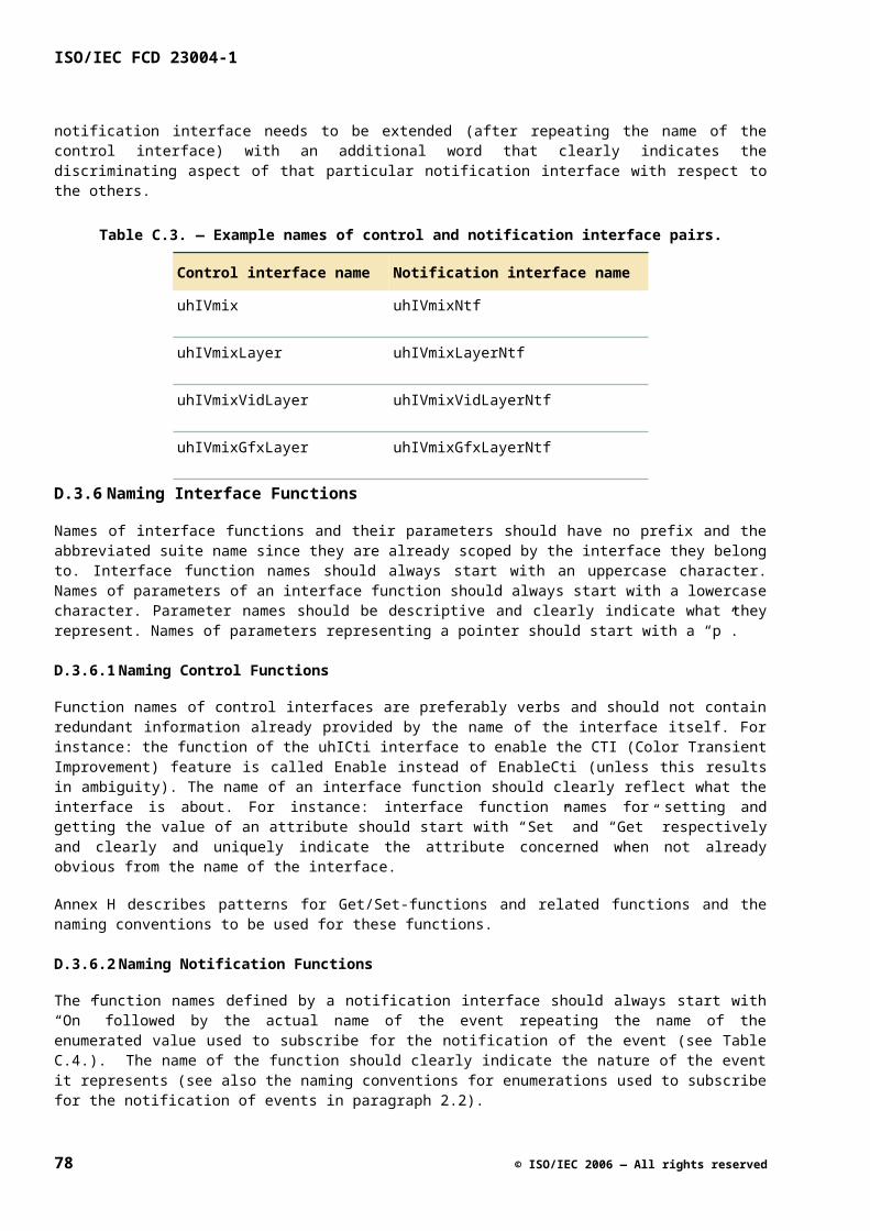
Annex G(informative)
Notification
G.1 Introduction
G.1.1 Summary
In this API specification we define the event notification mechanism as uniformly supported by M3W platform. This API specification is special in the sense that it does not define a single collection of interfaces but an “interface pattern” that can be “instantiated” in a concrete interface suite. This is due to the M3W platform having functional notification interfaces (one dedicated callback interface per set of events). The interfaces in this suite are therefore dependent on the “event signature” defining the names of the events to be notified and the types of their parameters.
An instantiation of the interface pattern defined by the notification interface suite consists of a notification interface, a subscription interface and a collection of special types and constants. These three entities are defined in this specification with the event signature acting as a parameter of the specification. Most UHAPI interface suites support event notifications and are therefore “based on” one or more instantiations of the notification interface suite defined in this API specification.
G.2 Concepts
G.2.1 Event Notification
The M3W provides “control interfaces” that allow a client of the M3W platform to control functionality provided by the platform. Besides controlling functionality, clients usually also wish to perform actions in reaction to events that occur in the platform. Examples of events are autonomous state changes, detection of signal changes, completion of asynchronous actions, etc. There are two different ways this event handling can be supported by an API, often characterized as the “pull” and the “push” models.
In the “pull” model the API provides functions to inspect the status of the platform. The client can use these functions to “poll” the platform for status changes and thus detect the occurrence of events and take action. In this model the responsibility for detecting the occurrence of events is put with the client. In the “push” model the platform takes the responsibility for this and notifies the client when events occur. On receiving the notification the client can take immediate action. Since the platform generates the events itself this is usually the more efficient solution in terms of overall performance as well as event handling latency.
The M3W supports the “push” model of event handling. This approach requires the client to provide a notification interface containing functions that will be called by the platform on the occurrence of events. These notification interfaces are functional interfaces, implying that there is a one-to-one correspondence between the functions in a notification interface and the (types of) events being notified through the interface. The structure of a notification interface is indicated below:
interface <prefix>IXYNtf : rcIUnknown{ Void OnEvent1( ... ); Void OnEvent2( ... ); ...}
© ISO/IEC 2006 — All rights reserved 79
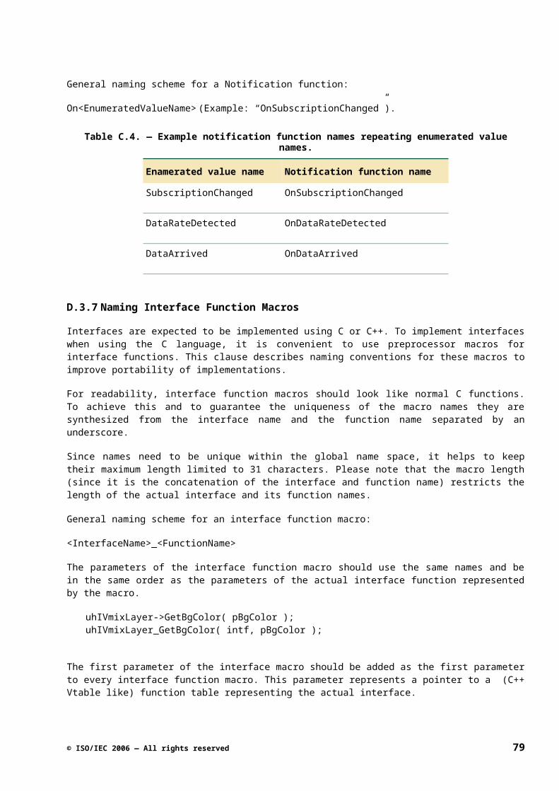
ISO/IEC FCD 23004-1
The variable parts are the X and Y parts of the notification interface name and the names of the events Event1, Event2, etc. X is the short name of the interface suite that the interface is part of (the “suite prefix”) and Y derives from the control interface that the notification interface is associated with (see below).
The grouping of notification functions in notification interfaces is typically based on the fact that the functions notify events related to the same role. These events usually originate from the “streaming behavior” and/or the “active behavior” of the role. Some events may be specific to an interface of a role, in particular events that report completion of asynchronous actions initiated by calls to functions in the interface.
G.2.1.1 Causes of a Notification
The value of an attribute may change autonomously (e.g. because of an interrupt), or via a Set function. In all cases, these changes are notified via a notification function. Even when the Set function is called two times with the same value, the client will receive two notifications. So, each autonomous change or assignment via a Set-function is notified.
By notifying assignments via Set-functions next to autonomous changes, no dependency is created between the part of the client software that actually controls an attribute and possibly another part of that software that actually observes the attribute. Furthermore, a model where only autonomous changes are signaled to the middleware can be emulated on top of this model. The rule that two invocations of Set with the same value leads to two notifications enables a simpler implementation in the platform (less error-prone), and supports the separation of the controlling part (that decided to make two invocations) and observing part for the attribute in the client software.
G.2.1.2 Notification Call provides Changed Data
A notification call passes the changed data by value or by reference. Attribute values are passed by value, by placing them on the stack. For large blocks of changed data, a reference to the data is passed. This referenced notified data is guaranteed to be valid until the notification function returns. Therefore, if the data is needed later on by the client after the notification function returns, it has to be copied. If two clients are subscribed to the same attribute, then both clients are notified with the same value, even if there is an attribute change in between both notifications.
If the data would not be included in the notification and the client performs a down call to obtain the data (Get-function), it is possible that the data already has been overwritten with a new value, as discussed in 1.4.1. Furthermore, providing the changed data in the notification function reduces the execution time (especially when passing a processor boundary), since no Get-functions have to be used to obtain this data.
G.2.2 Event Subscription
For reasons of efficiency it is not desirable that clients receive notifications of all events. Clients need some way to indicate that they wish to receive notifications of certain events only. The mechanism that achieves this is commonly referred to as event subscription. By subscribing to an event a client indicates that it wishes to receive notifications of the event and by unsubscribing it indicates that it no longer wishes to receive notifications of the event.
The M3W way of event notification and subscription complies with the “observer pattern” as described in [14]. We will use the same terminology as in [14] to refer to the object generating and notifying events, called the subject, and the object receiving notifications of events, called the observer. In M3W the providers of control interfaces act as subjects and the API clients act as observers.
Event subscription functionality is provided as part of the control interface(s) of a subject rather than being provided by a separate interface. For example, if a subject provides a control interface <prefix>IXY (where X is the suite prefix) and generates events that are notified to an observer, then <prefix>IXY will contain two standard functions Subscribe and Unsubscribe that allow the observer to selectively switch notifications on and off:
80 © ISO/IEC 2006 — All rights reserved

interface <prefix>IXY : rcIUnknown{ rcResult_t Subscribe( ... ); rcResult_t Unsubscribe( ... ); Function1; Function2; ...}
The Subscribe and Unsubscribe functions allow a set of notifications to be switched on and off in a single call. The set is specified as a parameter of these functions and the set values are constructed by logical “OR-ing” of values that represent the various types of event notifications. The typical structure of the data type definition that defines these values is indicated below:
typedef enum _<prefix>X_YNtf_t { uhX_YEvent1 = 0x00000001, uhX_YEvent2 = 0x00000002, uhX_YEvent3 = 0x00000004, uhX_YEvent4 = 0x00000008, ...} <prefix>X_YNtf_t, *p<prefix>X_YNtf_t;
NOTE the underscore between the X and Y parts of the type name.
Subscription and unsubscription works in an additive way. For example, if an observer subsequently subscribes to the sets of events {Event1,Event2} and {Event2,Event3} it will be subscribed to {Event1,Event2,Event3}. If it then unsubscribes to {Event1,Event2} it will still be subscribed to Event3.
The subscription and notification scheme as used in the UHAPI is schematically indicated in Figure F.1 —Single Subject and Single Observer, which shows a single subject and a single observer. As indicated in this figure, the following naming convention is used: if the name of the control interface is uhIXY, then the name of the corresponding notification interface is <prefix>IXYNtf.
Figure F.1 — Single Subject and Single Observer
© ISO/IEC 2006 — All rights reserved 81

ISO/IEC FCD 23004-1
G.2.3 Multiplicity Issues
A subject supports notifications to multiple observers. Each observer that provides the notification interface <prefix>IXYNtf associated with the subject can subscribe to notifications of events by the subject. In order for the subject to know which functions to call on occurrence of an event each observer should pass the pointer to its <prefix>IXYNtf interface when subscribing, as indicated in Figure F.2 — Single Subject andMultiple Observers. At the subject side these interface pointers act as identifications of the subscribed observers.
Figure F.2 — Single Subject and Multiple Observers
An observer with notification interface <prefix>IXYNtf may subscribe to events from multiple subjects. This implies that the same notification function in <prefix>IXYNtf may be called from different subjects, raising the question how the observer can determine from which subject a notification came. The problem is solved by allowing the observer to pass a special value to the subject when subscribing to a set of events. When an event occurs in the subject and the observer is subscribed to the event, this so-called cookie is passed back to the observer as a parameter of the notification function; see Figure F.3 — Multiple Subjects and SingleObserver.
82 © ISO/IEC 2006 — All rights reserved
Figure F.3 — Multiple Subjects and Single Observer
As follows from the above discussion, the following three parameters have to be passed by an observer when subscribing to event notifications:
74) The set of events that the observer wants to subscribe to.
75) The pointer to the notification interface of the observer.
76) The cookie that should be passed by the subject when notifying an event.
Since an observer may subscribe multiple times to events from the same subject the question arises what happens if different cookies are used in these subscriptions. For example, if the observer subscribes to {EventA,EventB} using cookie1 and then to {EventB,EventC} using cookie2 (where cookie1 ≠ cookie2) what will happen when EventA occurs? Will the subject pass cookie1 or cookie2 when notifying EventA? And what if EventB occurs?
The answer is that the subject treats each pair (observer,cookie) as the identification of a separate subscription. Each pair (observer,cookie) has its own set of subscribed events. So, in the above example, the subject will maintain two separate subscriptions for cookie1 and cookie2. The first is a subscription to {EventA,EventB} and the second is a subscription to {EventB,EventC}. When EventA occurs a single notification containing cookie1 will be sent to the observer. When EventB occurs two notifications will be sent to the observer (in unspecified order), one containing cookie1 and the other containing cookie2. This is indicated in the sequence diagram in Figure F.4 — Single Subject, Single Observer, Multiple Cookies.
When unsubscribing to events the same types of parameters are used as with subscribing except that the specified event notifications are interpreted differently. Unsubscribe will remove events from a subscription identified by a (observer,cookie) pair, rather than add events, as illustrated by Figure F.4 — Single Subject,Single Observer, Multiple Cookies. In order to completely cancel a subscription identified by a cookie, the set of all notifications should be used as parameter of the Unsubscribe function. For this purpose, and the purpose of enabling all notifications in a subscription, the special constant <prefix>X_YAllNtfs is provided.
© ISO/IEC 2006 — All rights reserved 83
ISO/IEC FCD 23004-1
Figure F.4 — Single Subject, Single Observer, Multiple Cookies
G.2.4 Execution Aspects
In order to allow for efficient implementations of the subscription and notification mechanism, in particular when subjects and observers reside in different process or processor domains, event subscription and notification is organized in a largely asynchronous way. More precisely:
The Subscribe and Unsubscribe functions are specified as asynchronous functions. This implies that observers do not have to wait until the actual (un)subscription has been performed. In order to let an observer synchronize with completion of the subscribe/unsubscribe action by the subject, the observer is given the opportunity to subscribe to a special SubscriptionChanged event. When subscribed to this event the subject will send a notification to the observer reporting the completion. The name of the corresponding notification function is OnSubscriptionChanged and it has two parameters: the cookie associated with the subscription and the new value of the subscription. The SubscriptionChanged event is dealt with in the same way as the application-specific events Event1, Event2, ... As a matter of fact, it is always the first in this list, i.e. Event1 == SubscriptionChanged. The first function in a notification interface is therefore always the OnSubscriptionChanged function. Figure F.5 — SingleSubject and Multiple Observers with OnSubscriptionChanged Notifications illustrates the use of OnSubscriptionChanged in the case of a subject with two observers.
84 © ISO/IEC 2006 — All rights reserved
Figure F.5 — Single Subject and Multiple Observers with OnSubscriptionChanged Notifications
Figure F.5 — Single Subject and Multiple Observers with OnSubscriptionChanged Notificationsshows several things:
When an observer subscribes to SubscriptionChanged events it will receive an OnSubscriptionChanged notification when the subscription has been completed, but when an observer unsubscribes to SubscriptionChanged events it will not receive a notification when the unsubscription has been completed.
OnSubscriptionChanged notifications are treated in a special way compared to the other notifications. When a subscription is changed this event is not notified to all subscribers to OnSubscriptionChanged but only to the observer associated with the changed subscription (provided that it is subscribed to OnSubscriptionChanged).
When subscribing to an event, an occurrence of the event after completing the call of Subscribe will not necessarily be notified but if the event occurs after receiving the corresponding OnSubscriptionChanged notification it will be notified.
When unsubscribing to an event, the event can still be notified after completing the call of Unsubscribe but not after receiving the corresponding OnSubscriptionChanged notification.
NOTE that the Subscribe and Unsubscribe functions being specified as asynchronous does not prevent them from being implemented as synchronous functions. The information whether or not Subscribe and Unsubscribe have been implemented as synchronous functions is typically found in a platform instance API specification.
No synchronicity properties are specified for notification functions implying that observers are free to define/implement them as synchronous as well as asynchronous functions. The synchronicity information is irrelevant to the subject because the subject always considers a notification completed when it returns from the call of the notification function.
© ISO/IEC 2006 — All rights reserved 85
ISO/IEC FCD 23004-1
Notification functions have to satisfy a number of constraints:
No return values or callbacks are expected by the subject, hence notification functions should return no result and have in-parameters only. This is also important to allow for efficient remote implementations of the notification mechanism (see below).
Since notification functions can be called “any time” they normally have precondition True. If not True, the precondition should be a condition that is (provably) true in all situations that the subject calls the notification function.
Notification functions should be “well-behaved” in the sense that they do not interfere with the behavior of the subject in an undesirable way. This general constraint is referred to as callback-compliance. It implies among other things that notification functions should be non-blocking and short, and that they may perform “down-calls” (calls of platform functions) under certain strict conditions only. These conditions are part of the M3W execution architecture and not further discussed here.
Apart from callback-compliance the behavior of a notification function is completely defined by the observer, which is reflected in the pre- and post-condition specification of a typical notification function:
Precondition True
Action Any callback-compliant action.
Postcondition True
A specific observer can fill in the “action” and strengthen the postcondition.
The fact that the subject calls notification functions asynchronously implies that the execution of the notification functions can be decoupled from the “normal” behavior of the subject. In particular, when subject and observer are in different process or processor domains the calls of the notification functions can be performed by a separate thread that is part of the proxy-stub code in the observer process or processor domain.
NOTE that, similar to the Subscribe and Unsubscribe functions, the notification functions being called asynchronously by the subject does not imply that a particular implementation cannot choose to call these functions synchronously.
As can be inferred from the above, each in-call of a subscribe/unsubscribe function will (conceptually) lead to a “pending” subscribe/unsubscribe action in the subject. Similarly, each occurrence of an event in the subject will (conceptually) result in a “pending” out-call to a notification function. There are no guarantees whatsoever with respect to the order of execution of these pending actions and calls by the subject. As an example of the notification of two different events, Figure F.6 — Asynchronous Events shows a stream of processing blocks, each with an event that is based on the contents of a stream. If a property changes in the stream, one could expect that the client first receives the OnAChanged event followed by the OnBChanged event. This ordering of events is however not guaranteed, since the two events are not related to the same subscription.
Figure F.6 — Asynchronous Events
86 © ISO/IEC 2006 — All rights reserved
The reason for not guaranteeing the ordering of different events is that the client does not benefit much from it probably, because it is likely to use a different set of variables for each individual subscription. Furthermore, a stricter guarantee would reduce API implementation freedom. If such a guarantee is essential, a different solution must be used (e.g. the use of time stamps).
There are two exceptions to the above:
Subscribe/unsubscribe actions relating to the same subscription (observer-cookie pair) are processed in first-in-first-out order, i.e. in the order the Subscribe/Unsubscribe functions were called.
Calls to notification functions relating to the same subscription (observer-cookie pair) are processed in first-in-first-out order, i.e. in the order of detecting the occurrences of the event.
This is schematically indicated in Figure F.7 — Asynchronous Event Subscription and Notification. Note that events for different observer-cookie pairs are not necessarily notified in the exact order they occur since most events are inherently asynchronous. The second rule implies, among other things, that different observers subscribed to the same set of events will receive the notifications of the events in the same order (but not necessarily at the same time).
Figure F.7 — Asynchronous Event Subscription and Notification
Observers may concurrently call the Subscribe and Unsubscribe functions. However, in order to allow for efficient implementations of the above ordering properties the following constraint is imposed on the use of the Subscribe and Unsubscribe functions: no two calls of (any combination of) the Subscribe and Unsubscribe functions may be in progress that operate on the same subscription (observer-cookie pair). In practice this is not a real constraint because concurrent access to the same subscription is something to be avoided anyway due to the inherent race conditions.
© ISO/IEC 2006 — All rights reserved 87
ISO/IEC FCD 23004-1
G.2.4.1 Relation between Notification and Get-function
When an attribute is changed, a notification is issued (passing its new value). Calling Get for an attribute might return a different value than the one passed in the notification, because the value might have changed again. (Note: Since the attribute value is also passed as an argument of the notification function, it is normally not required to do another Get of the same attribute.). So, calling a Get-function may return a value that has not been notified yet.
In Figure F.8 — Order of Actions, the order of actions is depicted in case of a change of an attribute:
77) An autonomous change of the value related to attribute A is occurring (left picture), or a Set function is being called to change the attribute (right picture).
78) The value of attribute A is updated.
79) The change of attribute A is notified to the client software.
Figure F.8 — Order of Actions
Therefore, calling GetA after step 2 but before step 3 returns already the new value A’ that has not been notified yet. In addition, subsequent calls of GetA can result in different values. So, an expression like ‘X*GetA + Y*GetA’ will result in an unpredictable result, since two different values of A may be used.
This notification behavior has been adopted because the multimedia domain is inherently multi-threaded. An approach in which a subsequent Get-function returns the same value as the last preceding notification is difficult to implement in such an environment, e.g. the last notified value would have to be cached and care must be taken not to lose attribute changes that have not been notified yet. For clients the notification behavior described in this sub clause is also suitable, since they obtain the new value as argument of the notification function; no calling of a Get-function for the attribute is needed. This behavior is also beneficial for clients that apply polling, since this way they always obtain the most recent value via a Get-function. It is also felt that this notification behavior is less error-prone and easier to explain.
G.2.5 Parameters of the Notification Interface Suite
The notification interface suite defined in this API specification is special in the sense that it does not define a single collection of interfaces but an “interface pattern” that can be “instantiated” in a concrete interface suite. This is due to M3W having functional notification interfaces (one dedicated callback interface per set of events). The interfaces in this suite are therefore dependent on the “event signature”, i.e. the names of the events to be notified and the names and types of their parameters.
The event signature can be identified with the signature of the corresponding notification interface which has the following structure:
88 © ISO/IEC 2006 — All rights reserved
interface <prefix>IXYNtf : rcIUnknown{ Void OnSubscriptionChanged( [in] UInt32 cookie, [in] <prefix>X_YNtfSet_t notifs ); Void OnEvent2( [in] UInt32 cookie, ... ); Void OnEvent3( [in] UInt32 cookie, ... ); ... Void OnEventn( [in] UInt32 cookie, ... );}
The parts that are variable per instantiation of the notification interface suite are indicated in italics and by means of ellipses. They are:
80) The interface suite prefix X.
81) The name Y deriving from the name <prefix>IXY of the control interface corresponding to the notification interface.
82) The number n indicating the number of events, where 1 ≤ n ≤ 32.
83) The names Event2, Event3, ..., Eventn of the application-specific events being notified.
84) The types, IDL attributes and names of the event parameters being passed in the notification functions. These are supposed to occur at the ellipses in the function parameter lists.
By providing concrete values for these parameters a concrete instantiation of the notification interface suite can be created. In the specification we will use the above parameters (indicated in italics) as placeholders for the values used in a concrete application of the notification interface suite. Strictly speaking, the names of the roles and attributes used in this specification are also parameters of the instantiation but we ignore them here because they are not visible to the user of the API.
A special complication is that in the M3W event subscription/unsubscription is not provided by separate interfaces but by including the subscribe/unsubscribe functions in control interfaces. In the specification of the notification interface suite we will nevertheless introduce a separate interface <prefix>IXYSubscribe for the subscription/unsubscription functionality, which can be viewed as an auxiliary interface that is never provided on its own. It is used in specifications of interface suites that are “based on” one or more instantiations of the notification interface suite to indicate that a control interface supports event subscription. That is, the <prefix>IXYSubscribe interface is defined by:
interface <prefix>IXYSubscribe : rcIUnknown{ rcResult_t Subscribe( ... ); rcResult_t Unsubscribe( ... );}
and a control interface <prefix>IXY that provides the Subscribe and Unsubscribe functions is defined by:
interface uhIXY : uhIXYSubscribe{ Function1; Function2; ...}
G.2.6 Instantiating the Notification Interface Suite
Most M3W interface suites support event notifications and are therefore “based on” the notification interface suite defined in this API specification. They include one or more instantiations of the notification interface
© ISO/IEC 2006 — All rights reserved 89
ISO/IEC FCD 23004-1
suite. The actual parameters of the instantiations are usually not made explicit; instead (the IDL of) the concrete notification interfaces and associated data types and constants are given from which the actual parameters can be derived.
A concrete instantation of the notification interface suite with parameters consists of the following items:
85) The subscription interface <prefix>IXYSubscribe.
86) The notification interface <prefix>IXYNtf.
87) The data type <prefix>X_YNtf_t defining values representing the individual notification functions.
88) The data type <prefix>X_YNtfSet_t representing sets (bit vectors) of values of type <prefix>X_YNtf_t.
89) The constant <prefix>X_YAllNtfs.
These items are specified in this API specification. The rights and obligations associated with them apply to all instantiations of the notification suite used in the other M3W specifications. These rights and obligations need therefore not be repeated; only additional requirements with respect to the notification interfaces have to be specified.
G.3 Types & Constants
G.3.1 Public Types & Constants
G.3.1.1 Error Codes
None.
G.3.1.2 <prefix>X_YNtf_t
Signature
typedef enum _<prefix>X_YNtf_t { <prefix>X_YSubscriptionChanged = 0x00000001, <prefix>X_YEvent2 = 0x00000002, <prefix>X_YEvent3 = 0x00000004, <prefix>X_YEvent4 = 0x00000008, ...} <prefix>X_YNtf_t, *p<prefix>X_YNtf_t;
Qualifiers
enum-element
Description
Values of this type represent notification functions. That is, there is a one-to-one correspondence between these values and the functions in the notification interface <prefix>IXYNtf. The first value is always <prefix>X_YSubscriptionChanged.
90 © ISO/IEC 2006 — All rights reserved

Values
Table F.1
Name Description
<prefix>X_YSubscriptionChanged Represents OnSubscriptionChanged.
<prefix>X_YEvent2Represents OnEvent2.
<prefix>X_YEvent3Represents OnEvent3.
<prefix>X_YEvent4Represents OnEvent4.
... etc.
G.3.1.3 <prefix>X_YNtfSet_t
Signature
typedef Int32 uhX_YNtfSet_t, *puhX_YNtfSet_t;
Qualifiers
enum-set
Description
Values of this type represent sets of notification functions which are typically constructed by logical OR-ing of values of type <prefix>X_YNtf_t. These values are used in the Subscribe and Unsubscribe functions to specify the event notifications to be enabled or disabled.
Constraints
None.
G.3.1.4 <prefix>X_YAllNtfs
Signature
const uhX_YNtfSet_t uhX_YAllNtfs =
( uhX_YSubscriptionChanged | uhX_YEvent2 | ... | uhX_YEventn )
Qualifiers
None.
Description
Defines the set of all values of type <prefix>X_YNtf_t. This constant can be used in calls of the Subscribe and Unsubscribe functions to enable or disable all event notifications, respectively.
© ISO/IEC 2006 — All rights reserved 91
ISO/IEC FCD 23004-1
G.3.2 Model Types & Constants
None.
G.4 Logical Component
G.4.1 Interface-Role Model
Figure F.9 — Interface-Role Model
The interface-role model of the notification interface suite reflects the general structure of the “observer pattern” [14]. The Subject role represents objects that can send notifications of internal events to interested objects. The Observer role represents the objects interested in receiving these notifications. Each subject provides facilities to subscribe/unsubscribe to event notifications through its <prefix>IXYSubscribe interface. Each observer provides a <prefix>IXYNtf interface containing functions that can be called by a subject to notify events.
G.4.2 Diversity
G.4.2.1 Provided Interfaces
Table F.2
Role Interface Presence
Subject <prefix>IXYSubscribe mandatory
92 © ISO/IEC 2006 — All rights reserved
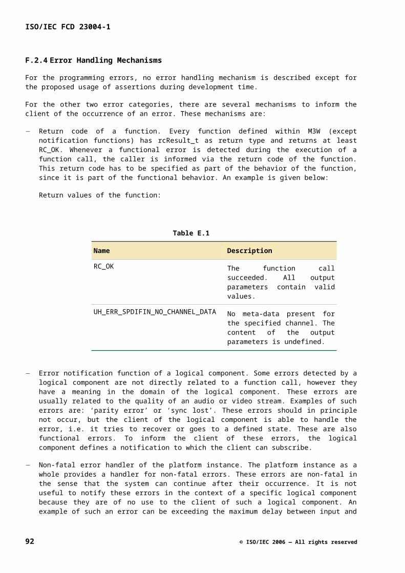
Role Interface Presence
Observer <prefix>IXYNtf mandatory
Note that even though the interface <prefix>IXYNtf is a mandatory interface of Observer, a concrete role R in an API specification can have it as an optional interface. The interpretation is that the role of Observer played by R is optional. If R plays the role of Observer it should provide the interface <prefix>IXYNtf, otherwise it should not.
G.4.2.2 Configurable Items
There are no configurable items, i.e. items that can be customized at instantiation time of a subject.
G.4.2.3 Constraints
None.
G.4.3 Instantiation
G.4.3.1 Objects Created
The following objects are created when the logical component is instantiated:
Table F.3
Type Object Multiplicity
Subject subject 1
G.4.3.2 Initial State
The following constraints apply to the initial state of a logical component instance:
For each Observer x and UInt32 c
subject.subscription[x,c] == {}
G.4.4 Execution Constraints
None.
G.5 Roles
G.5.1 Subject
Signature
role Subject { uhX_YNtfSet_t subscription[Observer,UInt32]; }
© ISO/IEC 2006 — All rights reserved 93
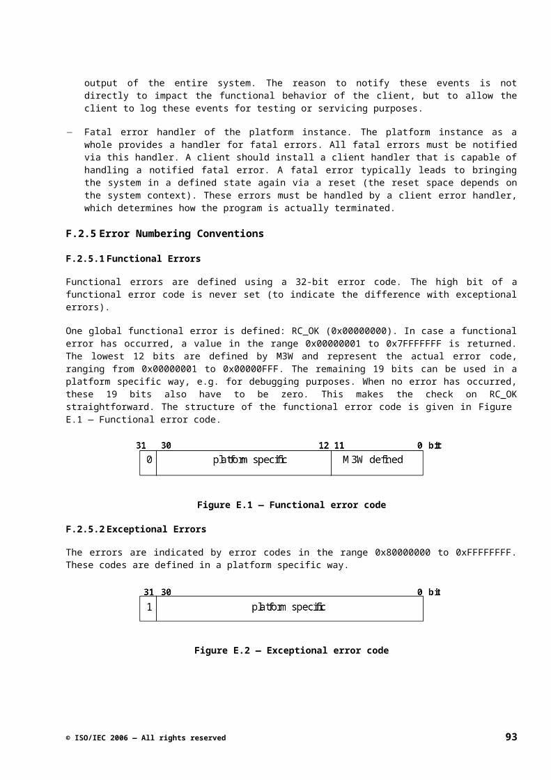
ISO/IEC FCD 23004-1
Qualifiers
None.
Description
An instance of the role Subject, called a subject, represents a provider of event notification functionality. A subject provides facilities to observers to subscribe/unsubscribe to notifications of a number of events. Whenever one of these events occurs it will notify all observers subscribed to the event.
Independent Attributes
Table F.4
Name Description
subscription[x,c] The set of event notifications subscribed to by observer x with associated cookie c. Only events corresponding to the notifications in this set will be notified. Initially this set is empty for each observer x and cookie c.
Dependent Attributes
None.
Invariants
None.
Instantiation
See G.4.3.
Streaming Behavior
None.
Active Behavior
The active behavior of a subject conceptually consists of two activities (see also G.2.4):
Executing pending subscribe/unsubscribe actions, i.e. actions that are a consequence of in-calls to the asynchronous Subscribe and Unsubscribe functions. No execution order is specified for these actions except for the subscribe/unsubscribe actions that relate to the same subscription (observer-cookie pair): they are serialized and executed in first-in-first-out order, i.e. in the order the Subscribe/Unsubscribe functions were called.
Executing asynchronous (i.e. potentially delayed) calls to the OnEvent notification functions (including OnSubscriptionChanged) in reaction to the occurrence of events. No execution order is specified for these calls except for the calls that relate to the same subscription (observer-cookie pair): they are serialized and executed in first-in-first-out order, i.e. in the order of detecting the events.
The active behavior associated with the subscribe/unsubscribe actions is defined by the specifications of the asynchronous Subscribe and Unsubscribe functions; see G.6.1.1 and G.6.1.2. The active behavior associated with the calls to notification functions is specified in the event-action table below. The implicit
94 © ISO/IEC 2006 — All rights reserved
assumption in all this is that the order of executing the subscribe/unsubscribe actions and the notifications is consistent with the two first-in-first-out rules described above.
Table F.5
Event Action
The subject has completed the execution of a pending subscribe/unsubscribe action on subscription[x,c], i.e. the subscription identified by observer x and cookie c.
If uhX_YSubscriptionChanged in subscription[x,c], the subject performs the following asynchronous function call: x.OnSubscriptionChanged(c,s)
where
s is the value of subscription[x,c] immediately after completion of the subscribe/unsubscribe action.
The subject detects the occurrence of Eventi, where i in {2,...,n}.
For each observer x and cookie c such that
uhX_YEventi in subscription[x,c]
the subject performs the following asynchronous function call: x.OnEventi(c,di,1,di,2,...)
where
di,1, di,2, ... is the data associated with the event.
Remarks
No order is specified for the asynchronous calls to notification functions when an event occurs. This order would be meaningless anyway because the calls are asynchronous.
The meaning of the Eventi events and the event data that is passed in the asynchronous calls of the OnEventi notification functions should be specified in the M3W specifications that are “based on” concrete instantiations of the notification interface suite.
Note that the OnSubscriptionChanged notifications are treated in a special way compared to the other notifications. When a subscription is changed this event is not notified to all subscribers to OnSubscriptionChanged but only to the observer associated with the changed subscription (provided that it is subscribed to OnSubscriptionChanged, of course).
Note that the specification of the active behavior of the subject implies that no OnSubscriptionChanged notification is sent when an observer unsubscribes the OnSubscriptionChanged notification even if the observer was subscribed to this notification at the time of unsubscribing.
G.5.2 Observer
Signature
role Observer {}
Qualifiers
actor
© ISO/IEC 2006 — All rights reserved 95
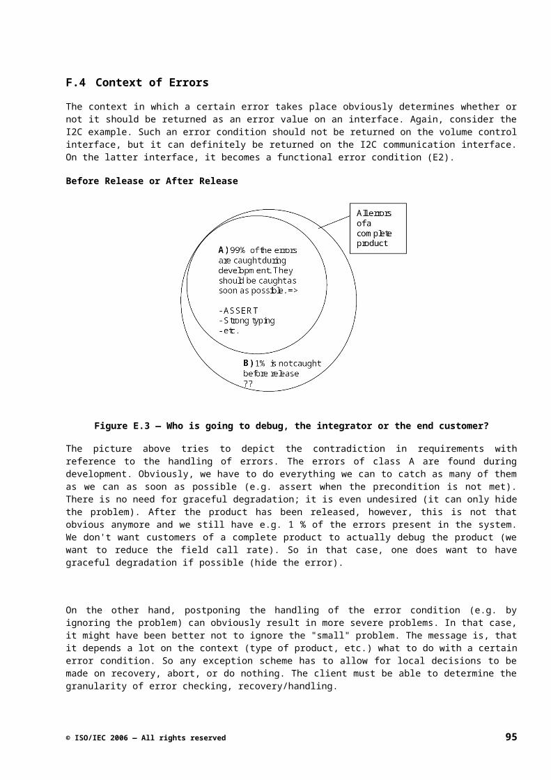
ISO/IEC FCD 23004-1
Description
An instance of role Observer, called an observer, represents a client of event notification functionality as provided by a subject.
G.6 Interfaces
G.6.1 <prefix>IXYSubscribe
Qualifiers
model-interface
Description
Defines the functionality to subscribe and unsubscribe to notifications of the events SubscriptionChanged, Event2, ..., Eventn. This is a model-interface because it is not used as an M3W interface by itself; the functions in this interface are always part of other interfaces, in particular control interfaces.
Interface ID
Not applicable because this is a model-interface.
Execution Constraints
No two calls of (any combination of) the Subscribe and Unsubscribe functions may be in progress that operate on the same subscription (observer-cookie pair). In other words, access to a specific subscription through Subscribe and Unsubscribe is single-threaded. This constraint should be enforced by the clients of the interface (the observers). Subscribe and Unsubscribe calls accessing different subscriptions may be fully concurrent. Note that this constraint applies to the calls of Subscribe and Unsubscribe only and not to the asynchronous actions associated with them.
Remarks
All functions provided by this interface are asynchronous. The asynchronous actions associated with these functions that relate to the same subscription (identified by an observer-cookie pair) are processed by the subject providing this interface in first-in-first-out order, i.e. in the order the functions were called. See the Active Behavior of Subject for more details.
G.6.1.1 Subscribe
Signature
rcResult_t Subscribe ( [in] <prefix>IXYNtf *pINotify, [in] UInt32 cookie, [in] <prefix>X_YNtfSet_t notifs );
Qualifiers
• asynchronous
Description
Adds a set of event notifications to a subscription of an observer.
96 © ISO/IEC 2006 — All rights reserved
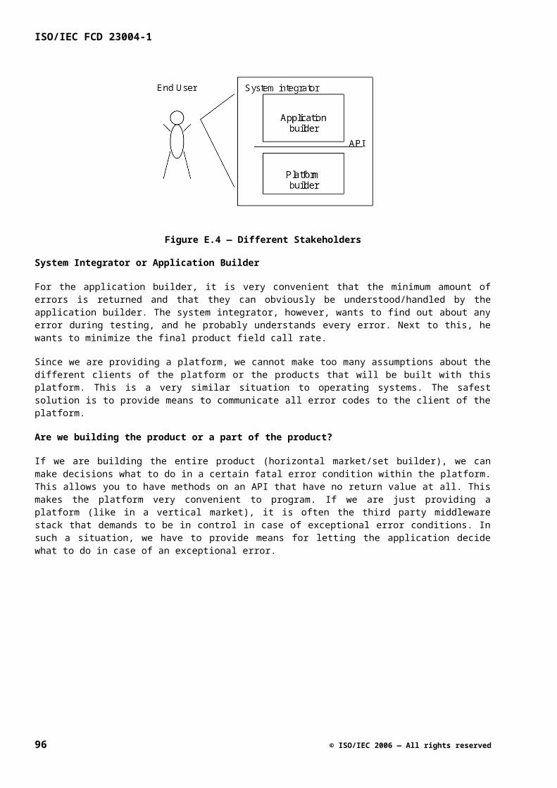
Parameters
Table F.6
Name Description
pINotify The pointer to the notification interface of the observer.
cookie The cookie that identifies the subscription of the observer and that is passed to the observer by the subject when notifying an event.
notifs The set of event notifications that the observer wants to add to its subscription.
Return Values
Standard.
Precondition
True
Asynchronous Action
Let observer be the provider of interface *pINotify
Modify subscription[observer,cookie]
Asynchronous Postcondition
subscription[observer,cookie] ==
subscription’[observer,cookie] notifs
Remarks
NOTE that the value of subscription’[observer,cookie] in the postcondition is always defined because each subscription is initially empty.
If the observer is subscribed to OnSubscriptionChanged notifications for the specified cookie, the completion of the asynchronous action will be notified to the observer together with the new value of the subscription. The observer may receive this notification before or after returning from the call to Subscribe. See the Active Behavior of Subject for more details.
If the observer is not subscribed to OnSubscriptionChanged and it subscribes to OnSubscriptionChanged, it will still receive an OnSubscriptionChanged notification when the subscription action is completed. This is because the observer indicated to be interested in receiving these notifications. See the Active Behavior of Subject.
Returning from a call to Subscribe does not guarantee that the observer will immediately receive the notifications in notifs relating to cookie. This guarantee can only be given after the matching OnSubscriptionChanged notification has been received by the observer, provided that the observer subscribed to this notification.
© ISO/IEC 2006 — All rights reserved 97
ISO/IEC FCD 23004-1
G.6.1.2 Unsubscribe
Signature
rcResult_t Unsubscribe ( [in] <prefix>IXYNtf *pINotify, [in] UInt32 cookie, [in] <prefix>X_YNtfSet_t notifs );
Qualifiers
asynchronous
Description
Removes a set of event notifications from a subscription of an observer.
Parameters
Table F.7
Name Description
pINotify The pointer to the notification interface of the observer.
cookie The cookie that identifies the subscription of the observer and that is passed to the observer by the subject when notifying an event.
notifs The set of event notifications that the observer wants to remove from its subscription.
Return Values
Standard.
Precondition
True
Asynchronous Action
Let observer be the provider of interface *pINotify
Modify subscription[observer,cookie]
Asynchronous Postcondition
subscription[observer,cookie] ==
subscription’[observer,cookie] \ notifs
98 © ISO/IEC 2006 — All rights reserved
Remarks
NOTE that the value of subscription’[observer,cookie] in the postcondition is always defined because each subscription is initially empty.
If the observer is subscribed to OnSubscriptionChanged notifications for the specified cookie, the completion of the asynchronous action will be notified to the observer together with the new value of the subscription. (There is one exception to this rule discussed in the next point.) The observer may receive this notification before or after returning from the call to Subscribe. See the Active Behavior of Subject for more details.
If the observer is subscribed to OnSubscriptionChanged notifications and unsubscribes the OnSubscriptionChanged notifications, it will not receive an OnSubscriptionChanged notification when the unsubscription action is completed. This is because the observer indicated no longer to be interested in these notifications. See the Active Behavior of Subject.
Returning from a call to Unsubscribe does not guarantee that the observer will no longer receive the notifications in notifs relating to cookie. This guarantee can only be given after the matching OnSubscriptionChanged notification has been received by the observer, provided that the observer subscribed to this notification.
G.6.2 <prefix>IXYNtf
Qualifiers
callback
Description
This interface is the notification interface as provided by an observer. It contains a notification function for each type of event that the subject can notify.
Interface ID
Defined in the API specification where the notification interface suite is instantiated.
G.6.2.1 OnSubscriptionChanged
Signature
Void OnSubscriptionChanged ( [in] UInt32 cookie [in] <prefix>X_YNtfSet_t notifs );
Qualifiers
None.
Description
This function is called by a subject when a subscription of the observer has been updated as a consequence of a call of the Subscribe or Unsubscribe function by the observer.
© ISO/IEC 2006 — All rights reserved 99
ISO/IEC FCD 23004-1
Parameters
Table F.8
Name Description
cookie The cookie identifying the updated subscription.
notifs The set of enabled event notifications immediately after completion of the Subscribe or Unsubscribe function, i.e. the value of the updated subscription.
Return Values
None.
Precondition
True
Action
Any callback-compliant action.
Postcondition
True
Remarks
See the Active Behavior of Subject for a detailed specification of the conditions under which this function is called.
For the definition of what is meant by a “callback-compliant action” see G.2.4.
G.6.2.2 OnEventi (i = 2, ..., n)
Signature
Void OnEventi ( [in] UInt32 cookie, ... );
Qualifiers
None.
Description
This function is called by a subject when it detects an occurrence of event Eventi.
100 © ISO/IEC 2006 — All rights reserved
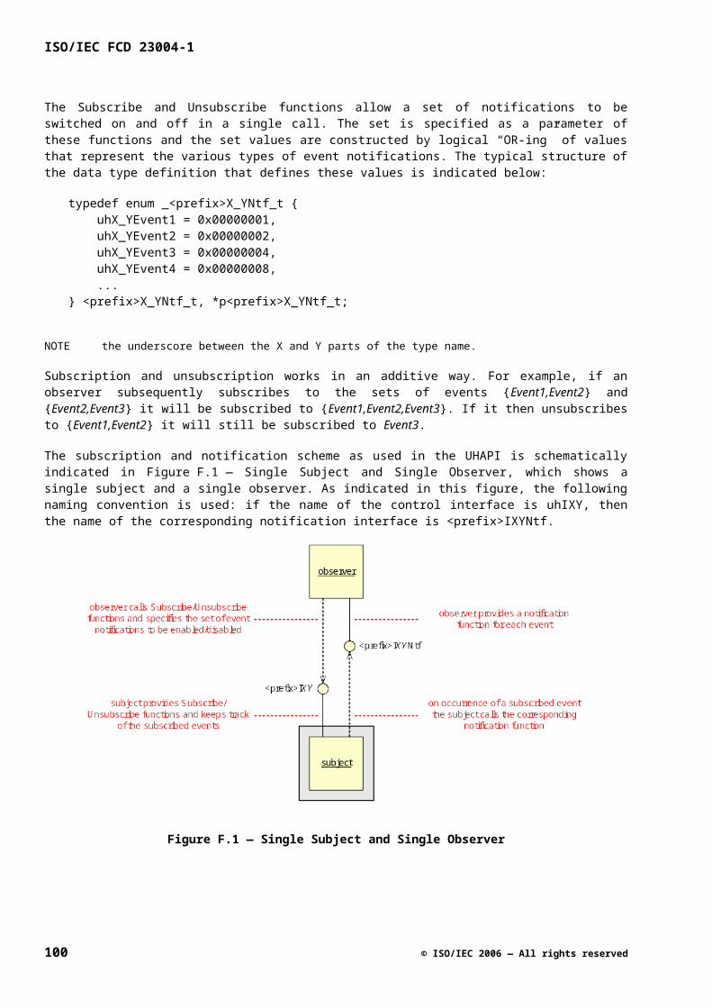
Parameters
Table F.9
Name Description
cookie The cookie identifying the subscription that enabled this notification.
... The parameters representing the data associated with the event.
Return Values
None.
Precondition
True
Action
Any callback-compliant action.
Postcondition
True
Remarks
See the Active Behavior of Subject for a detailed specification of the conditions under which this function is called.
For the definition of what is meant by a “callback-compliant action” see G.2.4.
As discussed in G.2.4 all parameters of this function should be in-parameters.
© ISO/IEC 2006 — All rights reserved 101
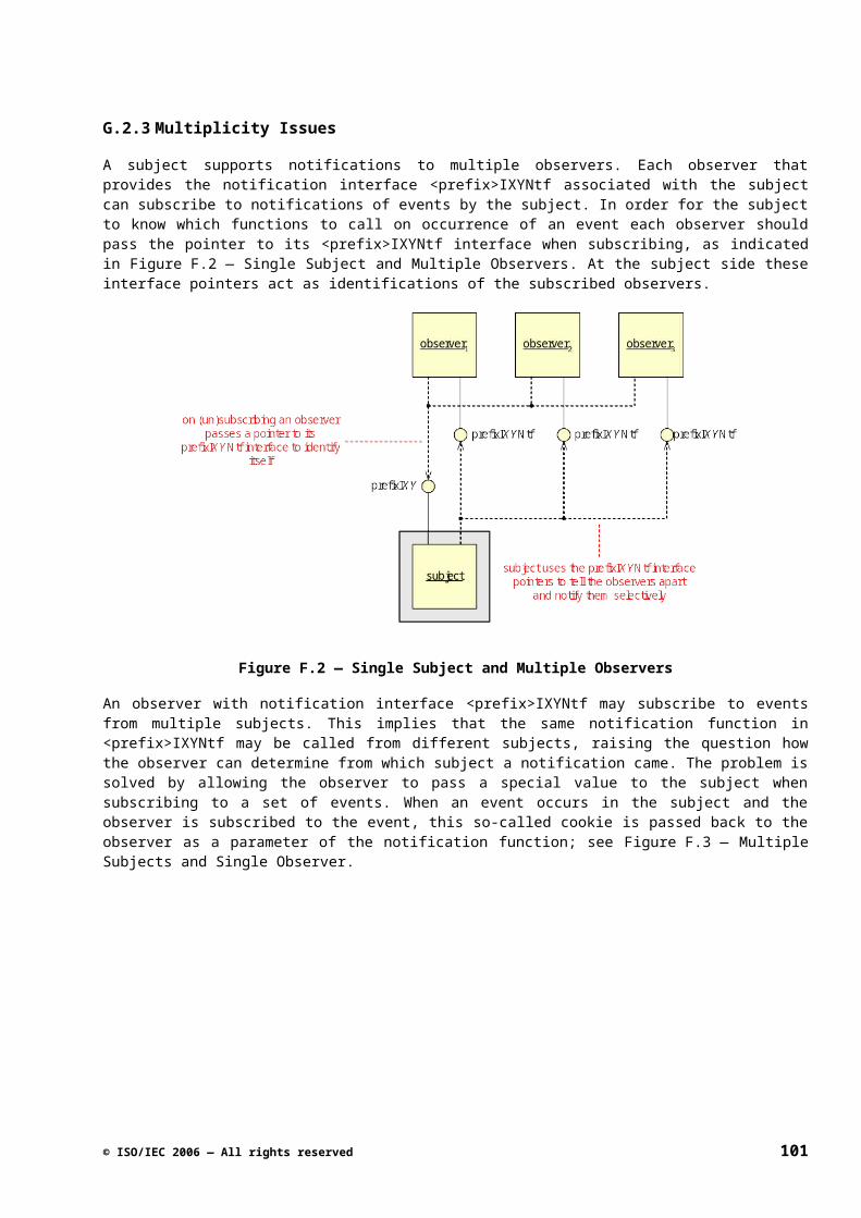
ISO/IEC FCD 23004-1
Annex H(informative)
Get Set Patterns
H.1 Introduction
H.1.1 Summary
This document gives an overview of the patterns related to Get and Set functions used within M3W interface suite specifications. These patterns will help to ensure consistency with respect to handling attributes in the API specifications. It can be noted that for certain cases, not just one single pattern should be used, but two or more patterns should be combined.
The Get/Set functions can also be related to notifications, e.g. setting a new attribute value may result in a notification.
H.2 General Get/Set Rules
H.2.1 General Rules
A set of Get and Set functions has in general the following syntax (example for the VolumeLevel attribute):
rcResult_t SetVolumeLevel ( [in] UInt32 level ); rcResult_t GetVolumeLevel ( [out] pUInt32 pLevel );
Below, general rules are given that apply to Get/Set functions:
If there is a Set-function there is always a Get-function.
Rationale: The implementation of the platform is very likely to record the actual value set. Providing a symmetrical Get-function avoids the necessity of the middleware to also record the specific value. Furthermore, both specifying and implementing a Get-function is extremely simple. Making the interface complete helps to make it less likely for the interface to change. In addition, a Get-function is desired from a testing point of view.
Each signal dependent observable attribute – in principle – needs to have an ‘Unknown’ value that indicates that ‘the data is available, yet it could not be determined’ and an ‘Invalid’ value that indicates that ‘the data is temporarily not available’. In case of an enumeration, these values are added to the enumeration modes, otherwise an additional attribute is introduced.
Rationale: There are cases in which the client needs to know the status of the measurement in case no valid value can be returned.
We do not define a step size for a Set-function (in case of a continuous value).
Rationale: Since the constants are not part of the client code, we can vary the maximum and the minimum values for every platform instance without breaking client code. Therefore, it is not necessary to have a step size. So, SetXxx(n) never equals SetXxx(n + 1) if both n and n + 1 are within the correct boundaries. (Note that one might say that this implicitly defines a step size of 1.)
102 © ISO/IEC 2006 — All rights reserved
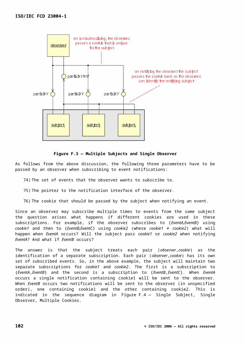
In certain cases, two or more attributes are related, e.g. a client always wants to have all values before taking action. In that case, the Get functions for these attributes can be combined into one function. The same holds for closely related attributes that can be modified via a Set function. In that case, there is one Set function for these attributes. When there is one Set or Get function for multiple attributes, then the corresponding notification function should also report the attributes together.
Rationale: Since the individual Get functions would always be called after each other, combining these calls into one function saves performance. Furthermore, combining related attributes in one function avoids race conditions, which may occur when separate functions are used.
It is not allowed to define an attribute that can be changed by both the client and the platform. If this behavior is needed, then two related attributes must be defined. For example, if the client can mute a signal and the platform can mute a signal autonomously, then two independent attributes clientMute and systemMute could be defined. Actual muting happens if either clientMute or systemMute is True.
Rationale: When two actors work on the same attribute, the behavior becomes complicated and race conditions can occur. To separate the actions of two actors, two attributes should be used instead.
Some attributes are related to physical units like decibel (dB). However, the attributes on the API are not directly expressed in physical units. The platform instance documentation may provide the mapping to physical units, though.
Rationale: If attributes would be expressed in physical units, it would put an (almost) unfeasible requirement on platform implementers to match the specification properly. Also, if the specification is tailored too much to match the specification a specific chip for instance, then it does often not match the specification of other chips.
H.2.2 Boolean Attributes
For Get/Set functions that deal with a Boolean value, EnableXxx and GetXxxEnabled are used instead of SetXxx and GetXxx. The following example illustrates this:
rcResult_t EnableAfc ( [in] Bool enable ); rcResult_t GetAfcEnabled ( [out] pBool pEnable );
The following decisions have been taken:
An Enable function does not have a mode parameter, but a Boolean.
Rationale: We want to use simple parameters as much as possible. It makes the interface more accessible since you do not have to look for the defined mode parameter and its related semantics.
GetEnabled will be used instead of IsEnabled to query for certain Boolean aspects that can be enabled or disabled.
Rationale: Given the fact that we cannot use the return value to return functional values (functions always return uhErrorCode_t), it is not possible to use
if (IsEnabled() …) …
Therefore, we treat these functions as any other Get-function.
There is a single Enable function with a Boolean parameter instead of separate Enable and Disable functions.
Rationale: Enable can be seen as “SetEnable”, and there is normally also a single Set-function.
© ISO/IEC 2006 — All rights reserved 103
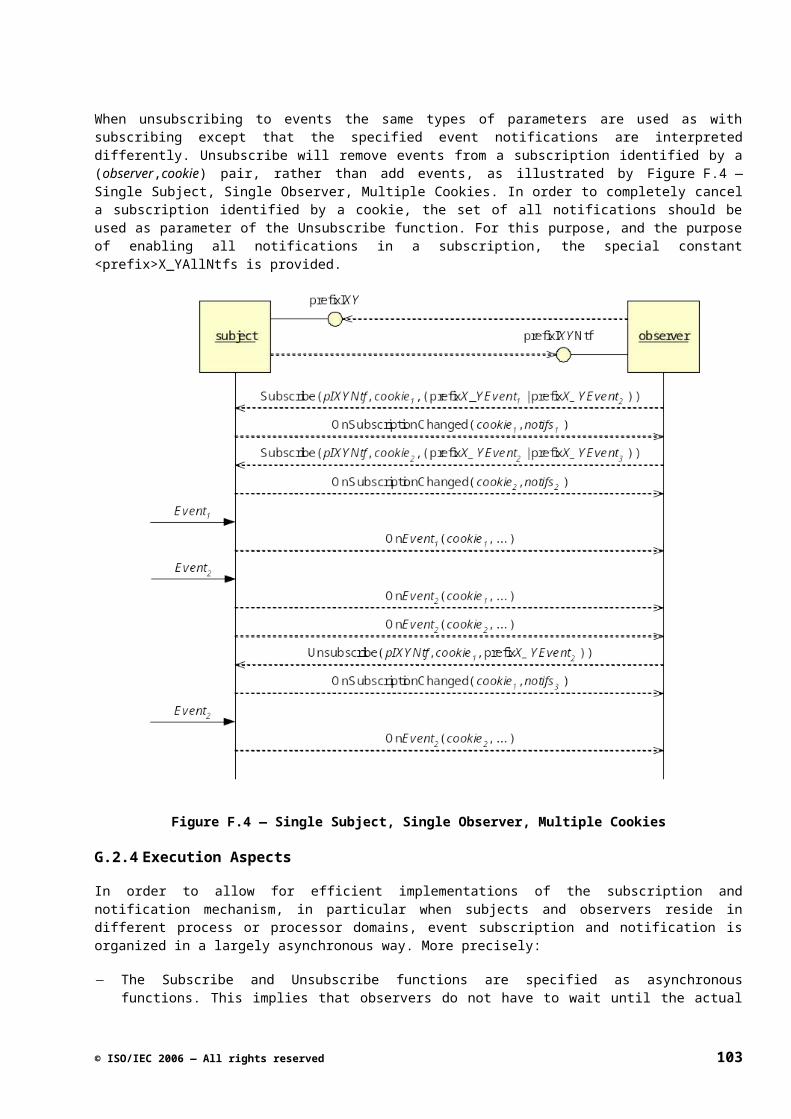
ISO/IEC FCD 23004-1
H.3 Patterns Overview
H.3.1 Identified Patterns
Get/Set functions can be used in different ways in API specifications. In this clause we give an overview of the various patterns that can be used. We have grouped these patterns in the following categories:
Discrete or continuous values
Get/Set functions can work on an attribute with a discrete or continuous value. In case of a discrete value, the used type can either be a ‘normal’ enumerator (H.4), or an enumerator of which the values can be used in a set (H.5). In case of an attribute with a continuous value, usually a range of allowed values is defined (H.6).
Attribute change
An attribute can change for the following reasons:
Change via Set function (client action)
In this case, the patterns as introduced above can be applied.
Autonomous change by the platform.
In case an attribute can only be changed by the platform, no Set function is present. An attribute is usually changed by the platform as a result of a change in the signal. The platform can continuously monitor the signal, with as a special case that the monitoring can be enabled or disabled (H.7) or only once upon request (H.8).
Change via Set and autonomous change
In some cases, a property can be both influenced by a Set function and an autonomous change by the platform. In this case, two attributes should be used, as illustrated in .
Handling diversity
The previous patterns focus on attributes that contain a functional value. There are also attributes that represent the presence of functionality. In this category, there are two get/set patterns, one for static diversity (H.10) and one for dynamic diversity (H.11).
For one attribute, several patterns can be applied at the same time.
H.3.2 Structure of the Patterns
The patterns described in the subsequent clauses all follow the same structure:
104 © ISO/IEC 2006 — All rights reserved
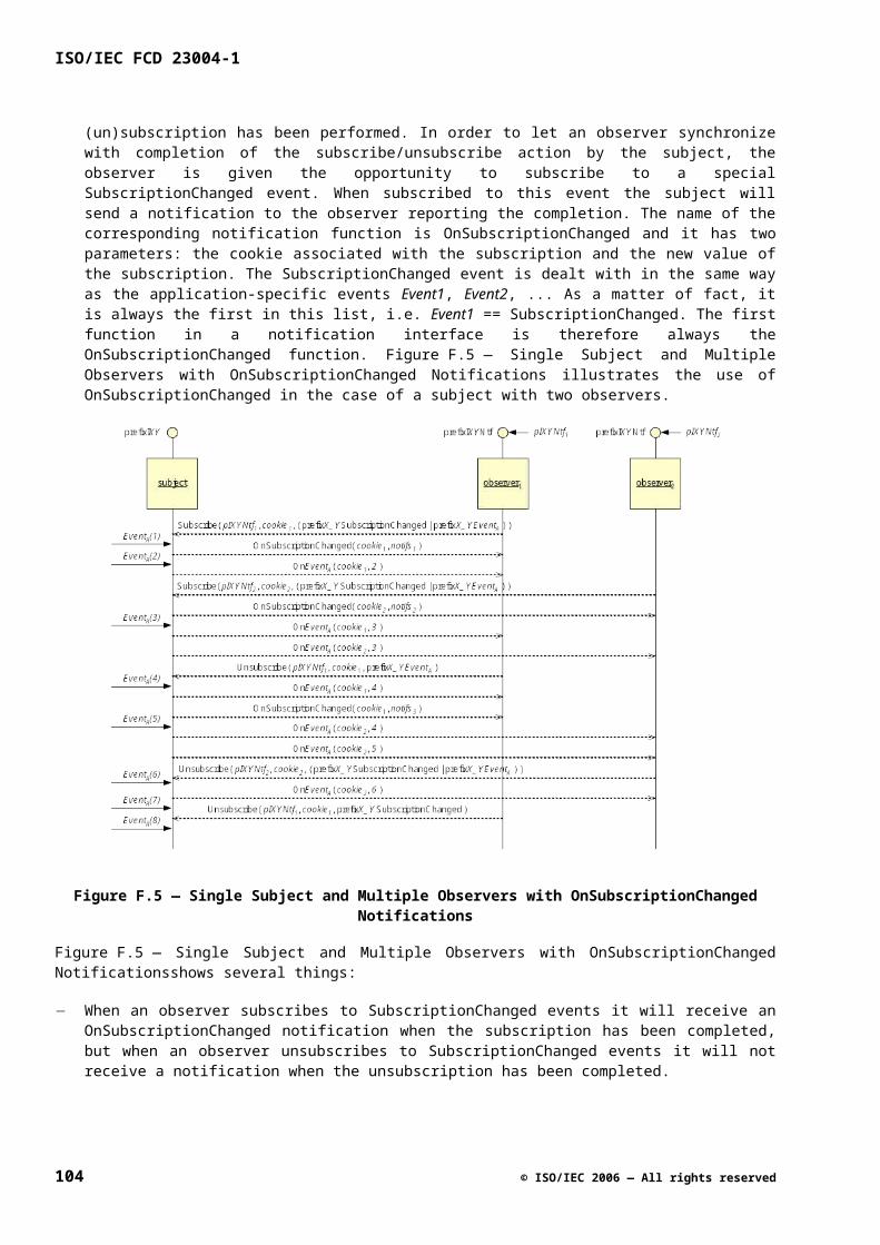
90) Intent; describes the intention of the pattern.
91) Applicability; describes when the pattern should be applied.
92) Specification; describes the elements in an API specification that belong to this pattern.
93) Specification Example; describes an example where this pattern is applied. In this sub clause, the example code is put on a grey background.
H.4 Attribute with Discrete Values
H.4.1 Intent
This pattern describes how to specify types and access functions to control a public attribute that has discrete values (using an enumeration).
H.4.2 Applicability
This pattern must be applied in all specifications with an attribute with discrete values that are not used in a set. If the values should be usable in a set, use the pattern described in H.5.
H.4.3 Specification
For this pattern, the following holds:
In the Types & Constants clause, define an enumerator (Qualifier: None) describing all discrete values. The used values are typically 0, 1, 2, 3, etc.
In the Roles clause, define the attribute <AttributeName> .
In the Logical Component clause, properly initialize <AttributeName>.
In the Interfaces clause, specify the functions Set<AttributeName>(<params>), Get<AttributeName>(<params>) in the order listed.
H.4.4 Specification Example
This example uses the following substitutions :
• <AttributeName> becomes NoiseGenChan and the attribute prefix is current.
In the Types & Constants cluse , uhAnoiseGen_ChanIndex_t is defined.
Signaturetypedef enum _uhAnoiseGen_ChanIndex_t {
uhAnoiseGen_None = 0,uhAnoiseGen_Left = 1,... uhAnoiseGen_Lfe = 10
} uhAnoiseGen_ChanIndex_t, *puhAnoiseGen_ChanIndex_t;
© ISO/IEC 2006 — All rights reserved 105
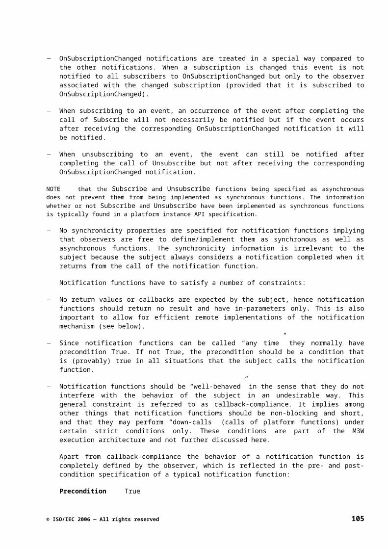
ISO/IEC FCD 23004-1
Qualifiers
None.
In the Roles clause, currentNoiseGenChan is defined.
Signature
role AnoiseGenerator { uhAnoiseGen_ChanIndex_t currentNoiseGenChan; ...; }
In the Logical Component clause, attribute currentNoiseGenChan is initialized.
Initial State
ang.currentNoiseGenChan == uhAnoiseGen_None
In the Interfaces clause, functions SetNoise and GetNoise are defined.
Table G.1
Subsection Specification example SetNoise
Signature uhErrorCode_t SetNoise (
...,
[in] uhAnoiseGen_ChanIndex_t chan );
Qualifiers single-threaded
Return values Standard
Pre-condition …
Action …
Modify ang.currentNoiseGenChan
Post-condition …ang.currentNoiseGenChan == chan
Table G.2
Subsection Specification example GetNoise
Signature uhErrorCode_t GetNoise (
…,
106 © ISO/IEC 2006 — All rights reserved
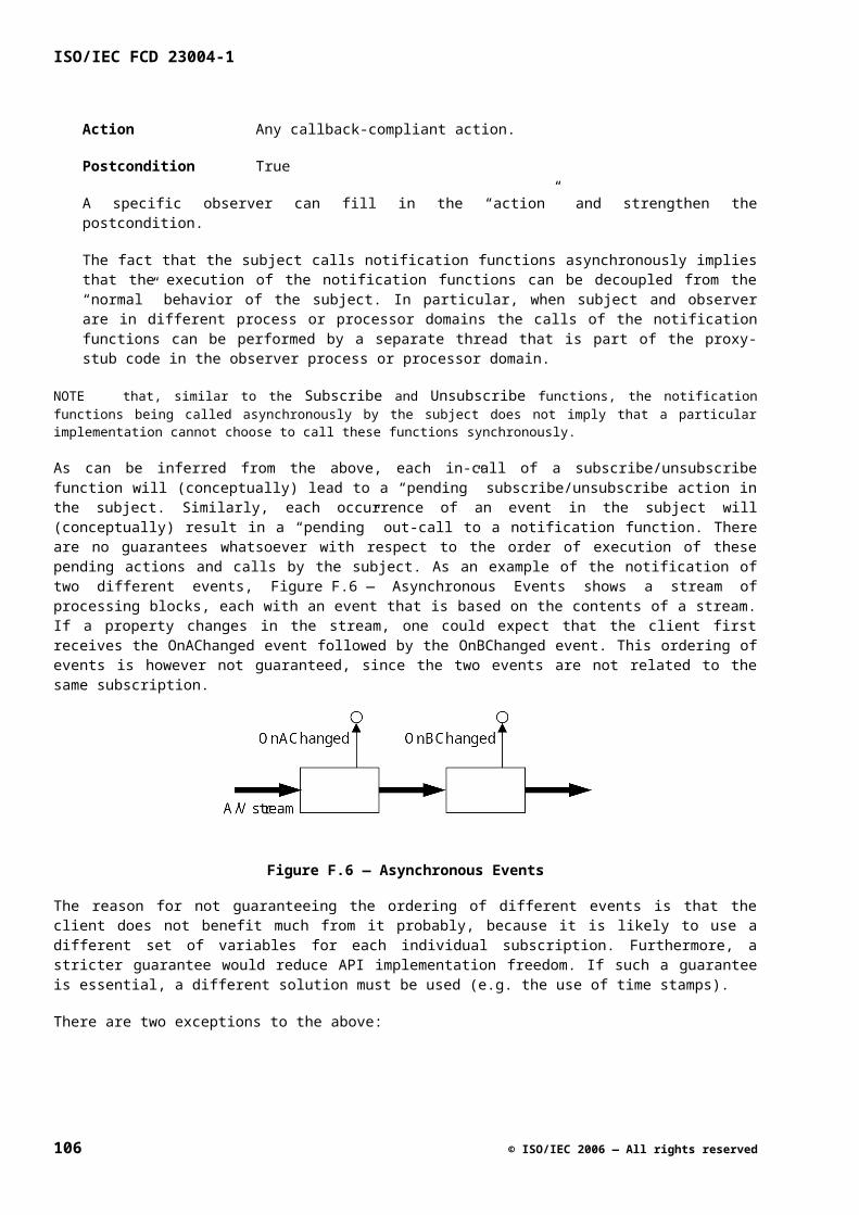
Subsection Specification example GetNoise
[out] puhAnoiseGen_ChanIndex_t pChan);
Qualifiers thread-safe
Return values Standard
Pre-condition True
Action None
Post-condition …*pChan == ang.currentNoiseGenChan
H.5 Attribute with Discrete Values used in a Set
H.5.1 Intent
This pattern describes how to specify types and access functions to control a public attribute that has discrete values (using an enumeration) used in a set.
H.5.2 Applicability
This pattern resembles the previous pattern. This pattern must be applied in all specifications with an attribute with discrete values that are used in a set. Typically, this is needed when a logical component instance only supports a subset of the discrete values; in this case the set of supported values can be obtained in the form of an OR-ed bit vector.
H.5.3 Specification
For this pattern the following holds:
In the Types & Constants subclause, define an enumerator (Qualifier: enum-element) describing all discrete values and an enumerator set (a type to represent one or more values; Qualifier: enum-set) for the type of the attribute. The used values are typically 0x00000001, 0x00000002, 0x00000004, etc.
In the Roles sub clause, define the attributes supported<AttributesName>s or supp<AttributeName>s for shortness (representing the set of supported attribute values) and <AttributeName>. Typically, the supported attribute values do not change during the lifetime of a role and thus supp<AttributeName>s can be defined as a const. An invariant can be used to express that <AttributeName> should have a value out of supported<AttributesName>s (plus possibly the additional initial value ).
In the Logical Component sub-clause, define supp<AttributeName>s as configurable item, define a constraint that Invalid and Unknown are not part of supp<AttributeName>s, if applicable. Properly initialize <AttributeName>, e.g. with <prefix>_<AttributeName>Unknown.
In the Interfaces sub-clause, specify the functions GetSupp<AttributeName>s(<params>), Set<AttributeName>(<params>), Get<AttributeName>(<params>) in the order listed.
© ISO/IEC 2006 — All rights reserved 107
ISO/IEC FCD 23004-1
Make sure the precondition of the Set<AttributeName>(<params>) function states that the value that is set is an element of supp<AttributeName>s.
Note:
GetSupp<AttributeName>s cannot be used in all cases. If it is very unlikely that the number of individual modes will ever exceed 32, this vector solution is the proper solution. In other cases, GetXxxModeSupp ([in] <prefix>XxxMode_t xxxMode, [out] pBool pSupported) should be used. This second mechanisms can be implemented easily and efficiently on top of the first one; the other way around is more expensive to implement. If a client wants to make a decision on a combination of supported modes, the use of the first mechanism is a cheaper solution.
In (almost) all cases, the fact whether a mode of an enumeration is supported or not is static. However, it might be possible for a certain attribute that the set of allowed modes changes dynamically, e.g. based on the signal. In that case, we use the term available instead of supported (see also the relation between the patterns in H.10 and H.11 on static and dynamic diversity). In such a case, a GetAvailableModes function is needed to check which modes can be used (possibly a corresponding notification function can be added where needed). A Set function for an attribute with a dynamically changing set of available modes will always return an error when an attribute is set to value that is currently not available for the current input signal. A strong precondition for such a Set function is not possible, because of race conditions. Since this pattern is currently not used, it is not explained in a separate clause.
H.5.4 Specification Example
The example below illustrates the case of discrete values that can be used in a set. It uses the following substitutions:
<prefix> becomes uhChanDec.
<AttributeName> becomes TxMode, and the attribute prefix is set.
In the Types & Constants sub-clause, uhChanDec_TxMode_t and uhChanDec_TxModeSet_t are defined.
Signature
typedef enum _uhChanDec_TxMode_t { uhChanDec_TxModeInvalid = 0x80000000, uhChanDec_TxModeUnknown = 0x40000000, uhChanDec_TxModeAuto = 0x00000001, uhChanDec_TxMode2k = 0x00000002, uhChanDec_TxMode8k = 0x00000004} uhChanDec_TxMode_t, *puhChanDec_TxMode_t;
Qualifiers
enum-element
Signature
typedef Int32 uhChanDec_TxModeSet_t, *puhChanDec_TxModeSet_t;
108 © ISO/IEC 2006 — All rights reserved
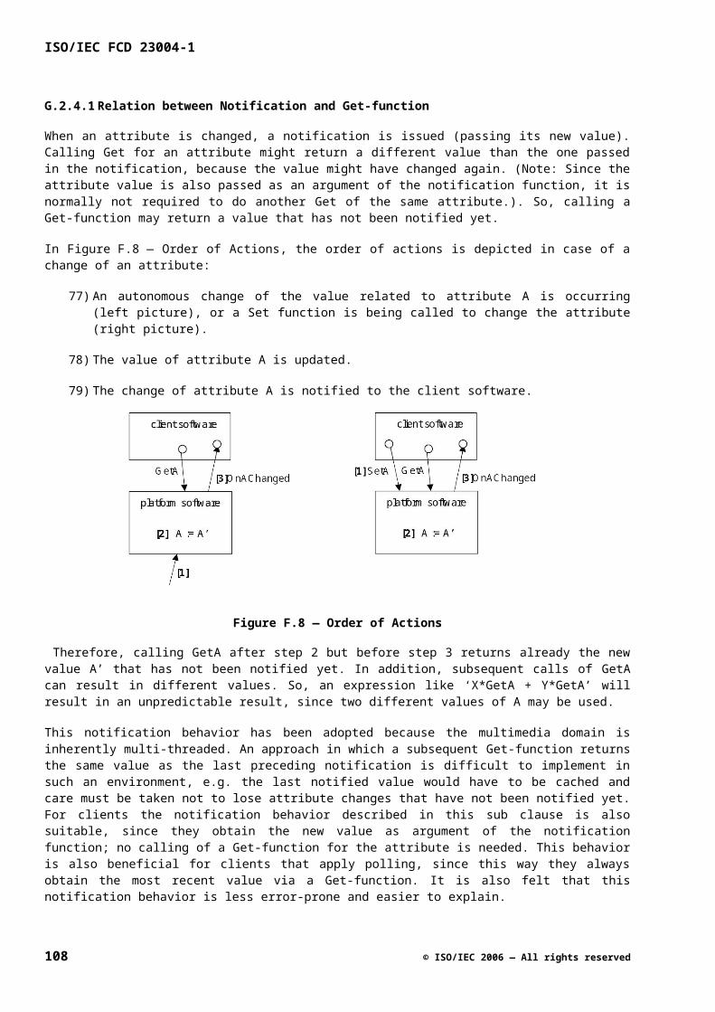
Qualifiers
enum-set
Description
This type defines the set-type for uhChanDec_TxMode_t.
In the Roles sub clause, suppTxModes and setTxMode are defined.
Signature role ChanDec { const uhChanDec_TxModeSet_t suppTxModes; uhChanDec_TxMode_t setTxMode; ...; }
Invariants
...
(setTxMode in suppTxModes)
|| (setTxMode == uhChanDec_TxModeUnknown)
...
In the Logical Component sub-clause, suppTxModes is defined as configurable item, and attribute setTxMode is initialized.
Configurable Items
Table G.3
Role Attribute
ChanDec suppTxModes
... ...
Constraints
suppTxModes does not contain uhChanDec_TxModeInvalid
suppTxModes does not contain uhChanDec_TxModeUnknown
Initial State
chd.setTxMode == uhChanDec_TxModeUnknown
© ISO/IEC 2006 — All rights reserved 109
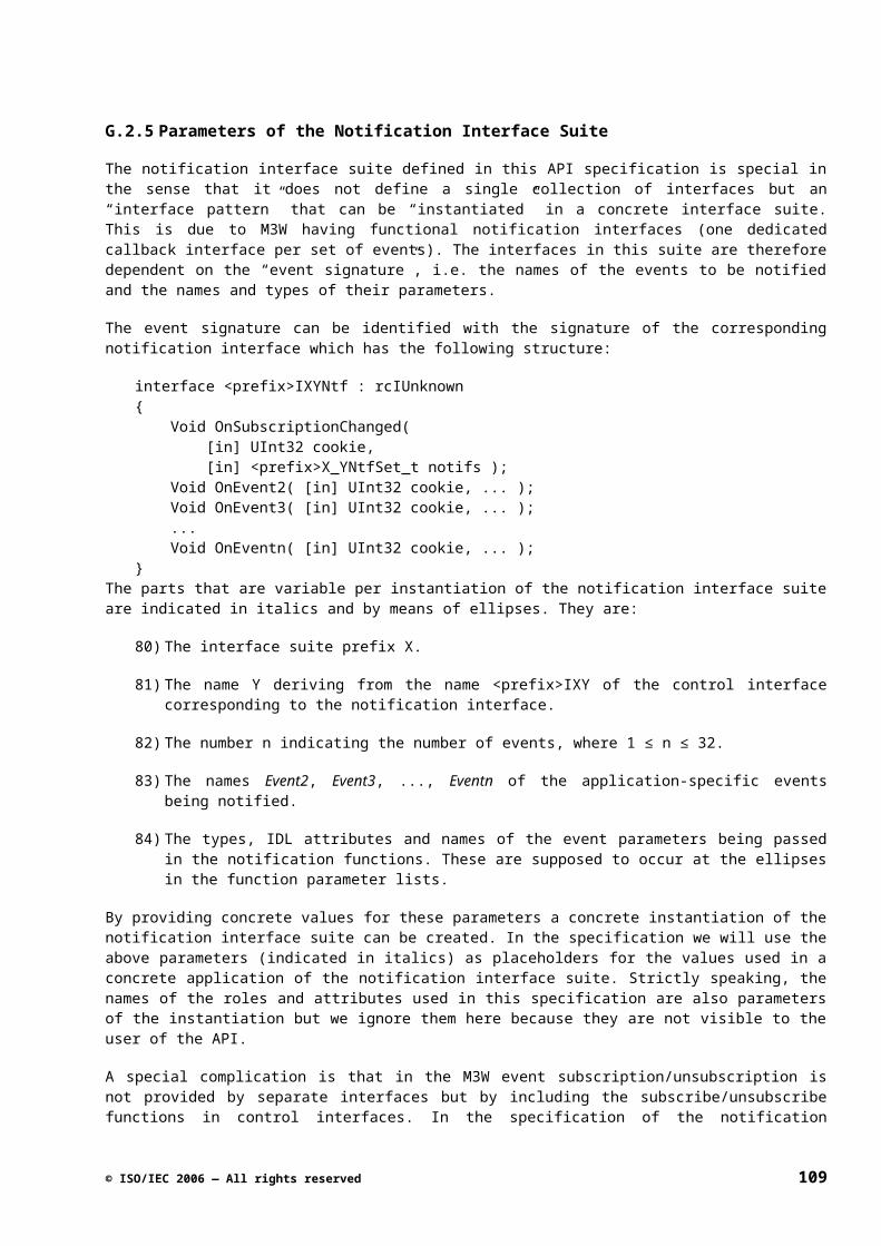
ISO/IEC FCD 23004-1
In the Interfaces subclause, functions GetSuppTxModes, SetTxMode, and GetTxMode are defined.
Table G.4
Subsection Specification example GetSuppTxModes
Signature uhErrorCode_t GetSuppTxModes (
[out] puhChanDec_TxModeSet_t pModes );
Qualifiers thread-safe
Return values Standard
Pre-condition True
Action None
Post-condition *pModes == chd.suppTxModes
Table G.5
Subsection Specification example SetTxMode
Signature uhErrorCode_t SetTxMode (
[in] uhChanDec_TxMode_t mode );
Qualifiers single-threaded
Return values Standard
Pre-condition mode in chd.suppTxModes
Action Modify chd.setTxMode
Post-condition chd.setTxMode == mode
Table G.6
Subsection Specification example GetTxMode
Signature uhErrorCode_t GetTxMode (
[out] puhChanDec_TxMode_t pMode );
Qualifiers thread-safe
Return values Standard
Pre-condition True
110 © ISO/IEC 2006 — All rights reserved
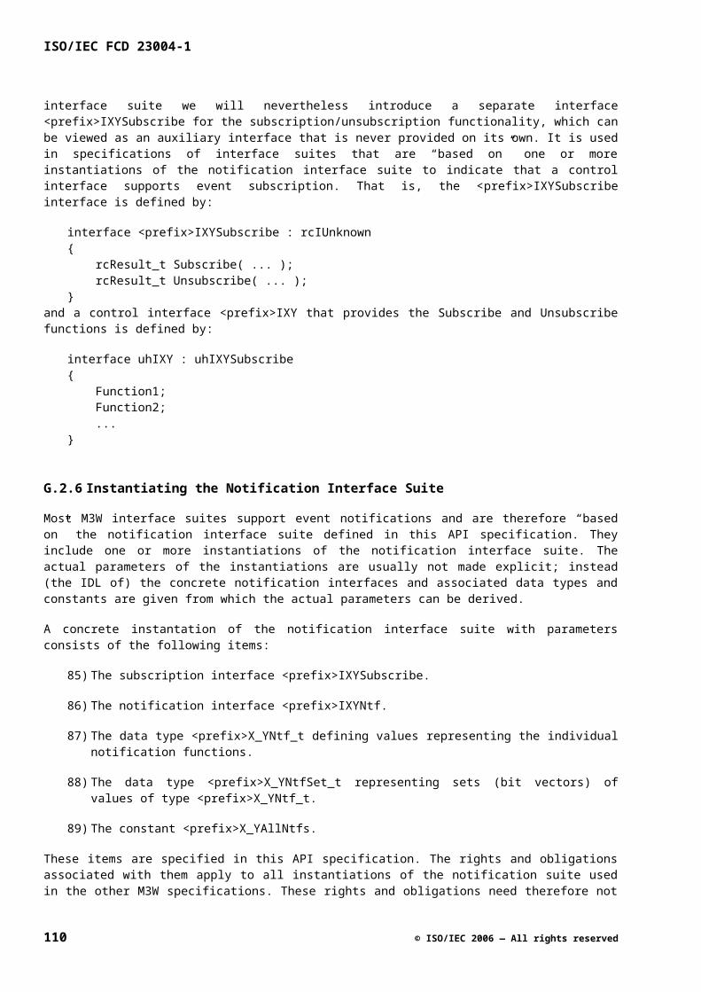
Subsection Specification example GetTxMode
Action None
Post-condition *pMode == chd.setTxMode
H.6 Attribute with Range of Continuous Values
H.6.1 Intent
This pattern describes how to specify access functions to control a public attribute with values out of a continuous range.
H.6.2 Applicability
This pattern must be applied in all specifications with an attribute with a continuous value. The value of such an attribute typically lies within a certain range.
H.6.3 Specification
For this pattern, the following holds:
In the Roles sub-clause, define the attributes min<AttributeName>, max<AttributeName> and <AttributeName>. Typically, the minimum and maximum values do not change during the lifetime of a role, and min<AttributeName> and max<AttributeName> can be defined as a const.
In the Logical Component subclause, define min<AttributeName> and max<AttributeName> as configurable items, add a constraint that the min value is smaller than (or equal to) the max value, and properly initialize <AttributeName> to for example the minimum value in range, or a value that is known to be always in range.
In the Interfaces subclause, specify the functions Get<AttributeName>Range(<params>), Set<AttributeName>(<params>), Get<AttributeName>(<params>) in the order listed.
Make sure the precondition of the Set<AttributeName>(<params>) function states that the value that is set is within the range min<AttributeName> and max<AttributeName>.
NOTE One function Get<AttributeName>Range is used to query for the minimum and maximum value instead of GetMin<AttributeName> and GetMax<AttributeName>. Since we cannot use the function return value for the minimum and maximum value anyway, it seems best to combine both the upper and the lower boundary into one function. This gives a small efficiency gain (as the client most probably needs both the minimum and maximum value) and reduces the specification effort.
NOTE The reason to define the domain of a Set-function via a Get function (Get<AttributeName>Range) and not via constants is as follows. A constant may not be defined in an include file since a ‘new’ component delivered in a binary form should not per se lead to recompilation of the client. Apart from this, we do want to have the freedom of different platform implementations to have different domains for certain functions.
H.6.4 Specification Example
This example uses the following substitutions:
© ISO/IEC 2006 — All rights reserved 111
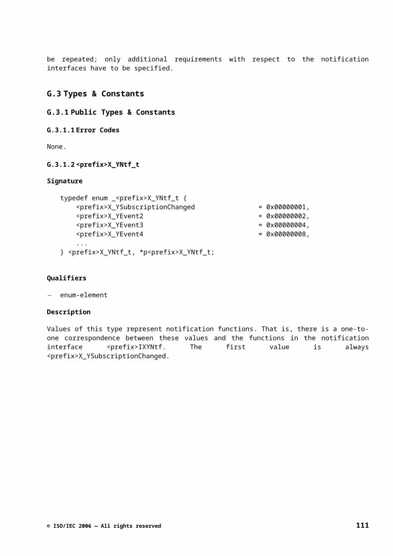
ISO/IEC FCD 23004-1
<AttributeName> becomes Level.
In the Roles sub-clause, the minLevel, maxLevel, and level attributes are defined.
Signature
role ColorTransientImprover { ... const UInt32 minLevel; const UInt32 maxLevel; UInt32 level;}
Invariants
minLevel <= level <= maxLevel
In the Logical Component sub-clause, minLevel and maxLevel are defined as configurable item, a constraint is added, and attribute level is initialized.
Configurable Items
Table G.7
Role Attribute
ColorTransientImprover minLevel
ColorTransientImprover maxLevel
... ...
Constraints
minLevel <= maxLevel
Initial State
cti.level == cti.minLevel
In the Interfaces sub-clause, functions GetLevelRange, SetLevel, and GetLevel are defined.
112 © ISO/IEC 2006 — All rights reserved
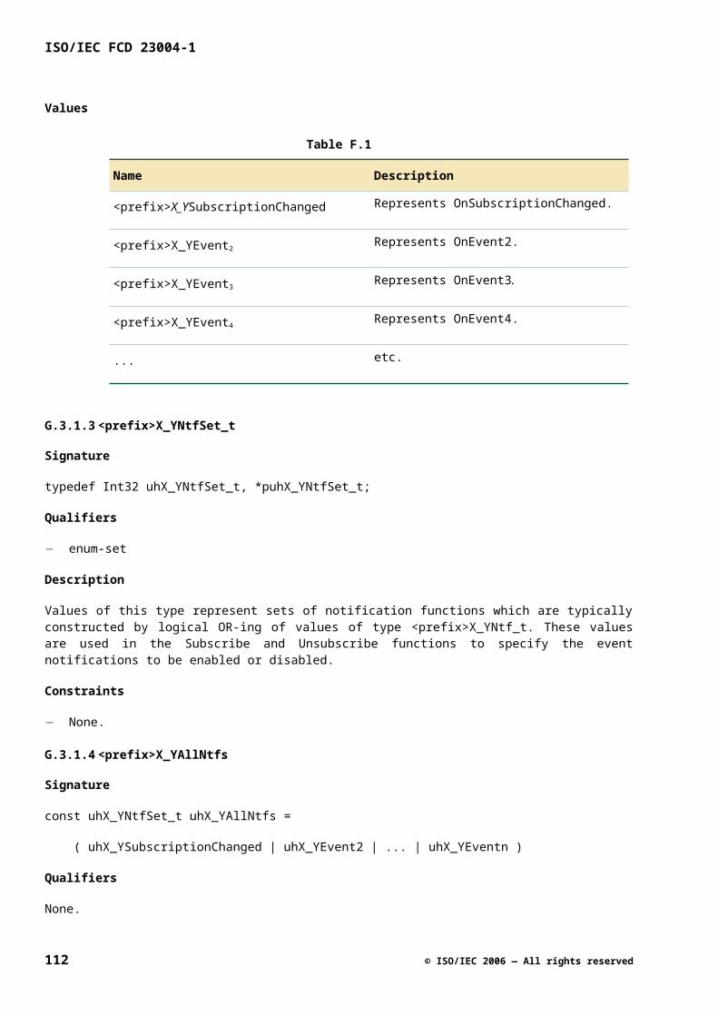
Table G.8
Subsection Specification example GetLevelRange
Signature uhErrorCode_t GetLevelRange (
[out] pUInt32 pMinLevel,
[out] pUInt32 pMaxLevel );
Qualifiers thread-safe
Return values Standard
Pre-condition True
Action None
Post-condition *pMinLevel == cti.minLevel
*pMaxLevel == cti.maxLevel
Table G.9
Subsection Specification example SetLevel
Signature uhErrorCode_t SetLevel ( [in] UInt32 level );
Qualifiers single-threaded
Return values Standard
Pre-condition cti.minLevel <= level <= cti.maxLevel
Action Modify cti.level
Post-condition cti.level == level
Table G.10
Subsection Specification example GetLevel
Signature uhErrorCode_t GetLevel ( [out] pUInt32 pLevel );
Qualifiers thread-safe
Return values Standard
Pre-condition True
Action None
© ISO/IEC 2006 — All rights reserved 113
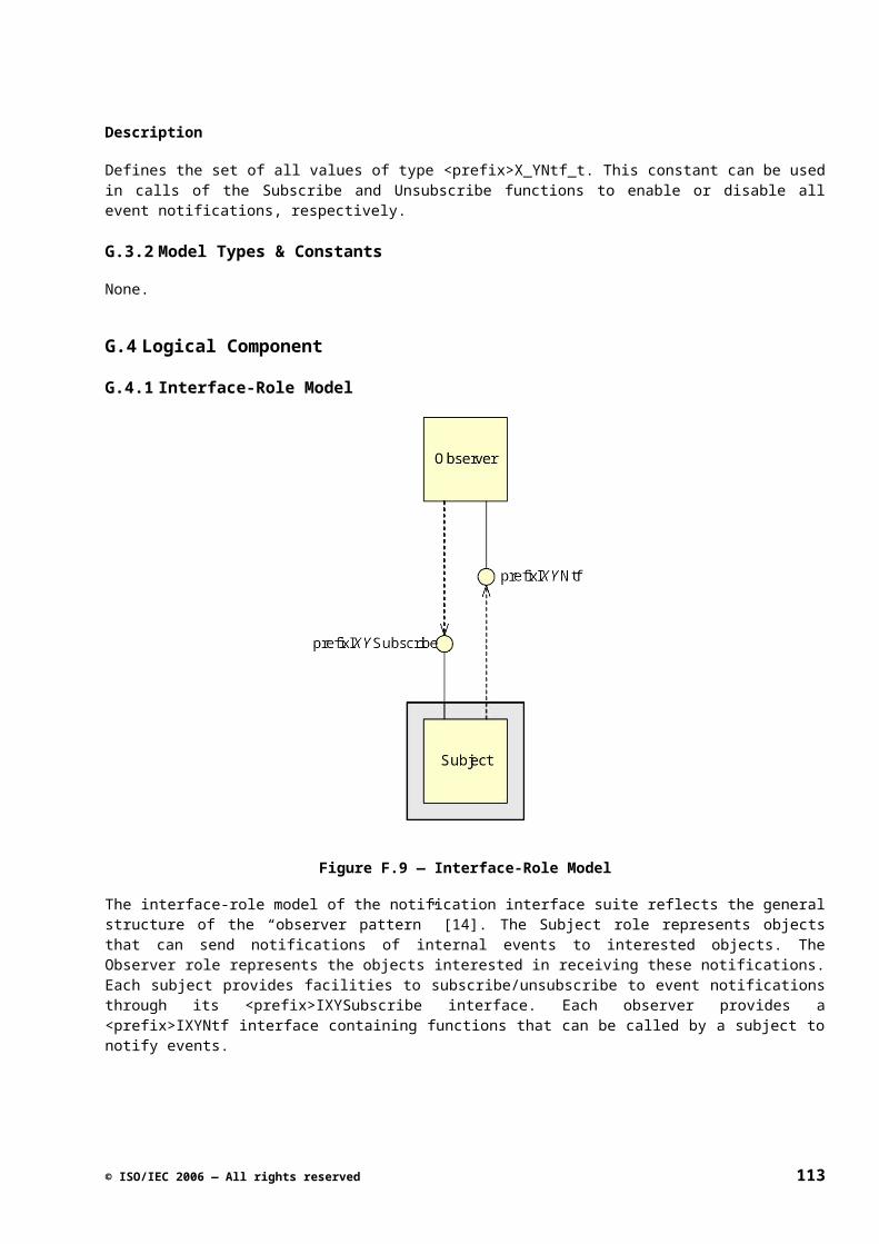
ISO/IEC FCD 23004-1
Subsection Specification example GetLevel
Post-condition *pLevel == cti.level
H.7 Continuous Measurement with Enable
H.7.1 Intent
This pattern describes how to specify access functions to control a continuous measurement that can be in state enabled or disabled.
H.7.2 Applicability
This pattern must be applied in all specifications with a continuous measurement that can be enabled of disabled.
H.7.3 Specification
For this pattern, the following holds:
In the Roles sub-clause, define the attributes <AspectName> Enabled and <AttributeName>.
In the Logical Component sub-clause, properly initialize <AspectName>Enabled, usually to False.
In the Interfaces sub-clause, specify the functions Enable<AspectName>(<params>), Get<AspectName>Enabled(<params>), Get<AttributeName>(<params>), in the order listed .
It must be specified what the behavior is when the function is not enabled and Get<AttributeName> is called. An option is to return the last measured value or Unknown.
H.7.4 Specification Example
The example uses the following substitutions:
<AttributeName> becomes level.
In the Roles sub-clause, the enabled and level attributes are defined.
Signaturerole NoiseMeter { Bool enabled; UInt32 level; ...}
Streaming Behavior
[...] When the NoiseMeter is disabled, the stream at the input is passed to the output without any measurement being done (level is not updated).
114 © ISO/IEC 2006 — All rights reserved
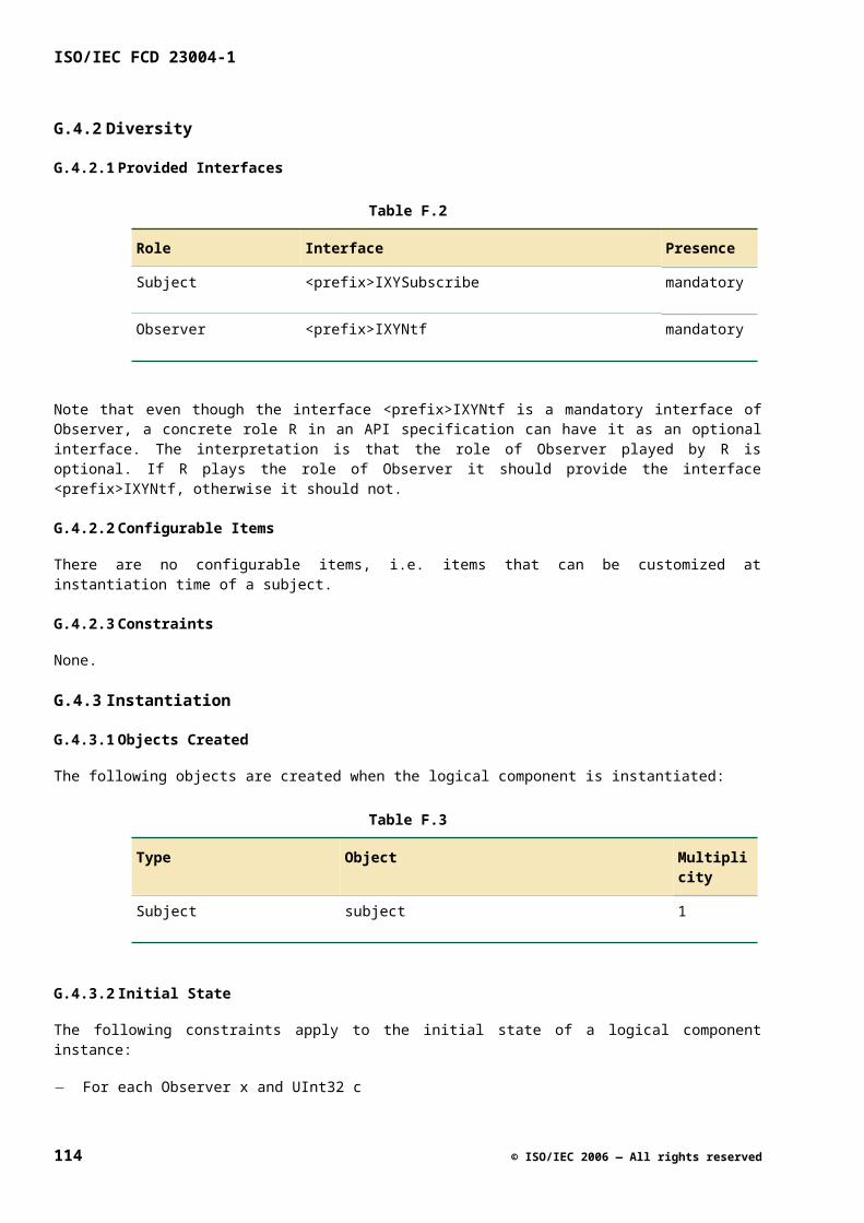
In the Logical Component sub-clause, initialize attribute enabled and level.
Initial State
• nm.enabled == False
• nm.level == undefined
In the Interfaces sub-clause, functions Enable, GetEnabled and GetLevel are defined.
Table G.11
Subsection Specification example Enable
Signature uhErrorCode_t Enable ( [in] Bool enable );
Qualifiers single-threaded
Return values Standard
Pre-condition …
Action Modify nm.enabled
Post-condition nm.enabled == enable
Table G.12
Subsection Specification example GetEnabled
Signature uhErrorCode_t GetEnabled ( [out] pBool pEnabled);
Qualifiers thread-safe
Return values Standard
Pre-condition True
Action None
Post-condition *pEnabled == nm.enabled
Table G.13
Subsection Specification example GetLevel
Signature uhErrorCode_t GetLevel ( [out] pUInt32 pLevel );
Qualifiers thread-safe
© ISO/IEC 2006 — All rights reserved 115
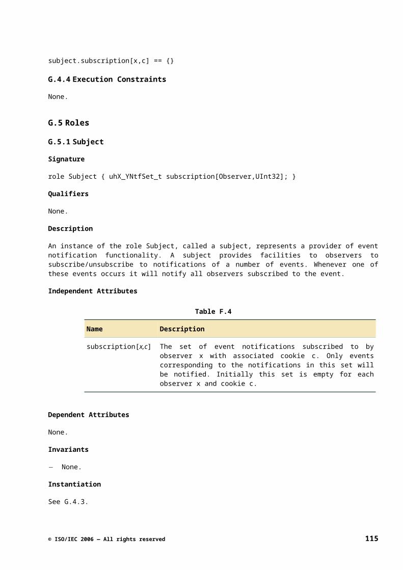
ISO/IEC FCD 23004-1
Subsection Specification example GetLevel
Return values Standard
Pre-condition True
Action None
Post-condition *pLevel == nm.level
H.8 One-shot Measurement
H.8.1 Intent
This pattern describes how to specify access functions to control a one-shot measurement.
H.8.2 Applicability
This pattern is seldom used. This pattern can be used when a logical component supports a measurement that is performed on request, e.g. because a constant measurement of that property affects the signal (intrusive).
H.8.3 Specification
For this pattern, the following holds:
In the Roles sub-clause, define the attribute <AttributeName>.
In the Interfaces sub-clause, specify the functions Measure(<params>), Get<AttributeName>(<params>), in the order listed. The Get<AttributeName> function can indicate via a Boolean whether a measurement is in progress or not.
NOTE A notification function should be defined to indicate when the measurement is completed.
H.8.4 Specification Example
The example uses the following substitutions:
<AttributeName> becomes SigStrength.
In the Roles sub-clause, the sigStrength attribute is defined.
Signature
role Measurer { UInt32 sigStrength; …}
116 © ISO/IEC 2006 — All rights reserved
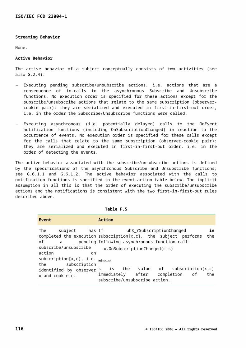
In the Interfaces sub-clause, functions Measure and GetSigStrength are defined.
Table G.14
Subsection Specification example Measure
Signature uhErrorCode_t Measure ();
Qualifiers single-threaded, asynchronous
Return values Standard
Pre-condition …
Action …
Post-condition …
Asynchronous action
…
notify OnMeasReady
Asynchronous post-condition …
Table G.15
Subsection Specification example GetSigStrength
Signature uhErrorCode_t GetSigStrength (
[out] pBool pMeasOngoing,
[out] pUInt32 pSigStrength );
Qualifiers thread-safe
Parameters pMeasOngoing Output parameter indicating if measurement is still ongoing (True) or not (False).
pSigStrength …
Return values Standard
Pre-condition True
Action None
Post-condition …
*pSigStrength == meas.sigStrength
© ISO/IEC 2006 — All rights reserved 117
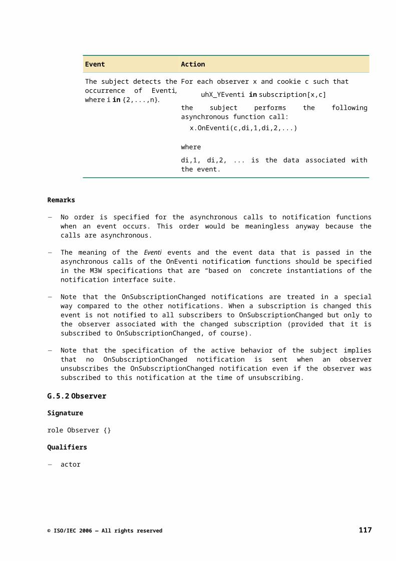
ISO/IEC FCD 23004-1
H.9 Autonomous Changing Attribute
H.9.1 Intent
This pattern describes how to specify types and access functions that control a property that can be changed by both the client and the platform.
H.9.2 Applicability
This pattern is useful when a customer sets a preference, but the platform indicates what is actually possible. To deal with two actors that can change the value, this pattern introduces two independent attributes. The value determined by the platform instance is the one that is actually used in the logical component.
H.9.3 Specification
For this pattern, the following holds:
In the Roles sub-clause, define the attributes set<AttributeName> (containing the value as set by the Set<AttributeName> function) and actual<AttributeName> (containing the actual attribute value as set by the platform instance).
In the Interfaces subclause, specify the functions Set<AttributeName>(<params>), Get<AttributeName>(<params>), GetActual<AttributeName>(<params>) (or GetAct<AttributeName> for shortness), in the order listed.
To indicate the difference between Get and GetActual, also GetPref can be used instead of just Get. The same holds for Set.
NOTE The behavior of the Get-function is that it returns the value of the last call of the related Set-function. Since the value that is actually used by the platform implementation may differ, a GetActual exists to retrieve the actual value used by the platform implementation.
NOTE In case of a discrete attribute, an enumeration (describing the individual modes) must be defined in the Types & Constants sub-clause. The enum may contain a prefix_<Attribute>Auto value that indicates that the platform must determine the appropriate mode. When this is the case, the actual attribute becomes <prefix>_<Attribute>Unknown until the new mode is determined by the platform.
NOTE Since two attributes are used in this pattern, also two notification functions are needed to notify changes in these attributes, e.g. OnActModeChanged, and OnPrefModeChanged (if required).
H.9.4 Specification Example
This example deals with a continuous attribute. It uses the following substitution:
<AttributeName> becomes Freq.
In the Roles sub-clause, the setFreq and actualFreq attributes are defined. (Changing the setFreq will result in an action to change the actualFreq to match the set value as closely as possible)
Signature
role Tuner { UInt32 setFreq; UInt32 actualFreq; …}
118 © ISO/IEC 2006 — All rights reserved
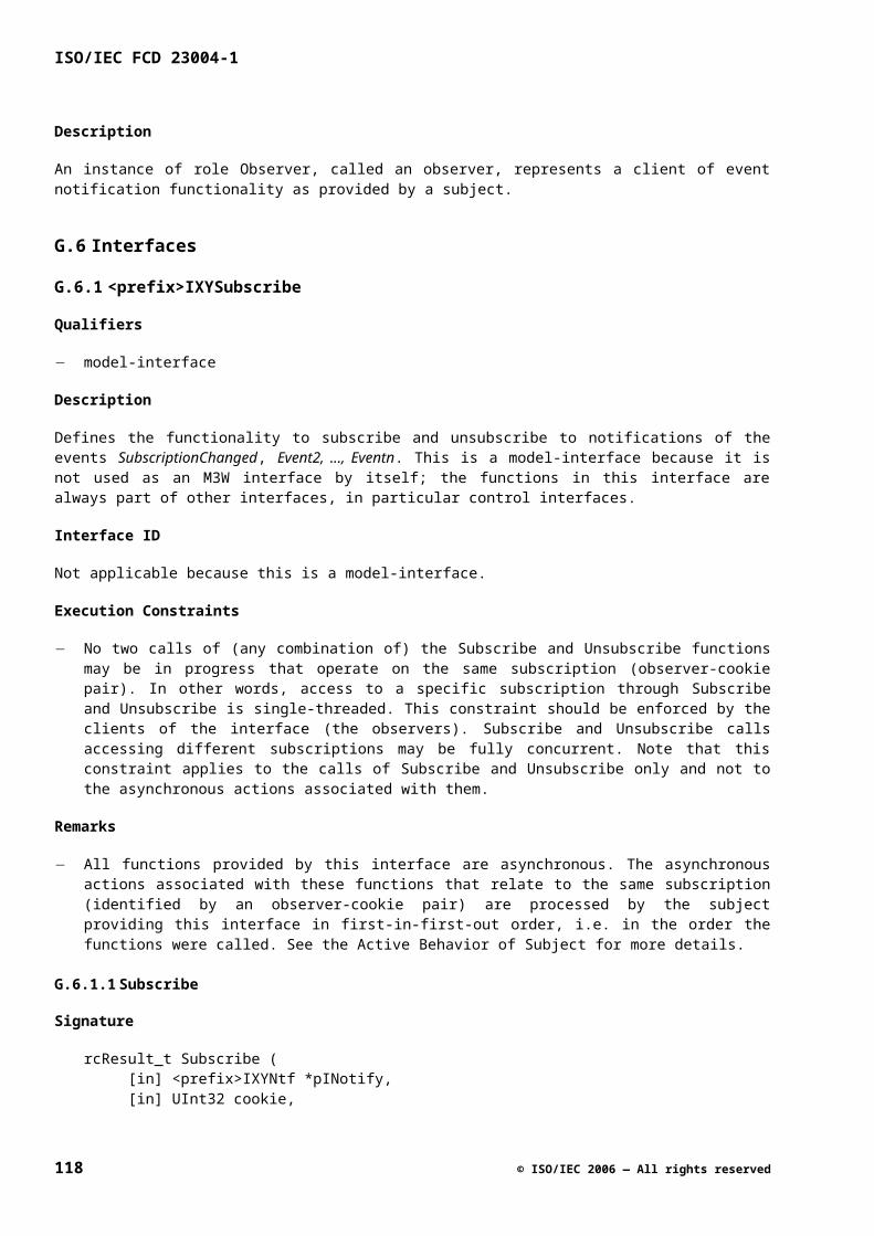
In the Interfaces sub-clause, functions SetFreq, GetFreq and GetActualFreq are defined.
Table G.16
Subsection Specification example SetFreq
Signature uhErrorCode_t SetFreq (
[in] UInt32 freq,
… );
Qualifiers single-threaded, asynchronous
Return values Standard
Pre-condition …
Action Modify tuner.setFreq
…
Post-condition tuner.setFreq == freq
…
Asynchronous action1
…
Modify tuner.actFreq
…
Asynchronous post-condition …
Table G.17
Subsection Specification example GetFreq Specification example GetActualFreq
Signature uhErrorCode_t GetFreq (
[out] pUInt32 pFreq,
… );
uhErrorCode_t GetActualFreq (
…,
[out] pUInt32 pFreq);
Qualifiers thread-safe thread-safe
1 In this example, the “actual attribute” is changed as part of the asynchronous action. The “autonomous changing attribute” pattern, however, does not prescribe this. For instance, it is also possible that changes in the “actual attribute” are triggered by a role’s active behavior.
© ISO/IEC 2006 — All rights reserved 119
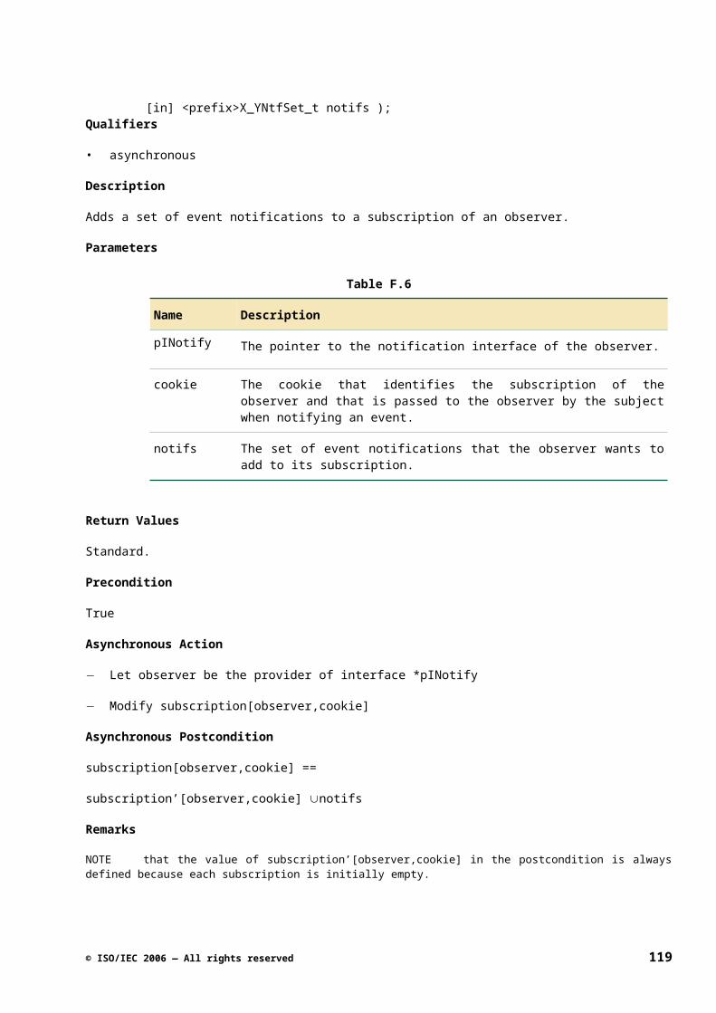
ISO/IEC FCD 23004-1
Subsection Specification example GetFreq Specification example GetActualFreq
Return values Standard Standard
Pre-condition True True
Action None None
Post-condition *pFreq == tuner.setFreq
…
*pFreq == tuner.actualFreq
…
H.10 Static Diversity on Function Level
H.10.1 Intent
This pattern describes how to specify functions that indicate whether certain functionality is supported or not. Whether this functionality is supported is determined at the creation time of a logical component instance.
H.10.2 Applicability
This pattern should be avoided when possible. Instead of this pattern, factor out the optionally supported functionality in a separate interface and use QueryInterface to determine whether certain functionality is supported. Sometimes this is not possible, for example because it would result in too many very small interfaces; in that case, we use this pattern to query if something is supported.
H.10.3 Specification
For this pattern, the following holds:
In the Roles sub-clause, define the attribute <AttributeName>Supported or <AttributeName>Supp for shortness (indicating whether the functionality is supported). Typically, <AttributeName>Supp does not change during the lifetime of a role, and can thus be defined as a const (configurable item).
In the Logical Component sub-clause, define <AttributeName>Supp as configurable item. No initial state is given, since this is platform instance specific.
In the Interfaces sub-clause, specify the functions Get<AttributeName>Supp(<params>), Set<AttributeName>(<params>), Get<AttributeName>(<params>) (or Get<AttributeName>Supp(<params>), Enable<AttributeName>(<params>), Get<AttributeName>Enabled(<params>)) in the order listed.
Make sure the precondition of the Set<AttributeName>(<params>) and Get<AttributeName>(<params>) functions states that the attribute is supported.
H.10.4 Specification Example
The example uses the following substitutions:
120 © ISO/IEC 2006 — All rights reserved
<AttributeName> becomes bg(Color).
In the Roles sub-clause, the bgSupp attribute is defined.
Signature
role Layer { ... uhColor_t bgColor; const Bool bgSupp; ...}
In the Logical Component sub-clause, bgSupp is defined as configurable item.
Configurable Items
Table G.18
Role Attribute
Layer bgSupp
... ...
In the Interfaces sub-clause, function GetBgSupp, SetBgColor, and GetBgColor are defined.
Table G.19
Subsection Specification example GetBgSupp
Signature uhErrorCode_t GetBgSupp ( [out] pBool pBgSupp );
Qualifiers thread-safe
Return values Standard
Pre-condition True
Action None
Post-condition *pBgSupp == layer.bgSupp
Table G.20
Subsection Specification example SetBgColor
Signature uhErrorCode_t SetBgColor ( [in] uhColor_t bgColor );
Qualifiers single-threaded
© ISO/IEC 2006 — All rights reserved 121
ISO/IEC FCD 23004-1
Subsection Specification example SetBgColor
Return values Standard
Pre-condition layer.bgSupp == True
Action Modify layer.bgColor.
...
Post-condition layer.bgColor == bgColor
Table G.21
Subsection Specification example GetBgColor
Signature uhErrorCode_t GetBgColor ( [out] puhColor_t pBgColor );
Qualifiers thread-safe
Return values Standard
Pre-condition layer.bgSupp == True
Action None
Post-condition *pBgColor == layer.bgColor
H.11 Dynamic Diversity on Function Level
H.11.1 Intent
This pattern describes how to specify functions that indicate whether certain functionality is currently available. During the lifetime of a logical component instance, this availability may change.
H.11.2 Applicability
This pattern can be applied in all specifications where the availability of functionality is determined by the data stream. This type of diversity cannot be handled via QueryInterface, since according to the COM rules, an interface cannot dynamically appear and disappear. The same holds for a function within an interface.
It must be clear to the client why a feature is not available. The documentation must specify this. If there are multiple reasons why a feature is not available, then the client must be informed of the reasons why a feature is not available. The various reasons must be expressed in the domain of the client and such that the client knows how to proceed.
H.11.3 Specification
For this pattern, the following holds:
122 © ISO/IEC 2006 — All rights reserved
In the Roles sub-clause, define the attribute <AttributeName>Available or <AttributeName>Avail for shortness (indicating the availability of some functionality).
In the Logical Component sub-clause, <AttributeName>Avail is not defined as configurable item, since the value depends on the actual input stream.
In the Interfaces sub-clause, specify the functions Get<AttributeName>Avail(<params>), Set<AttributeName>(<params>), Get<AttributeName>(<params>) (or Get<AttributeName>Avail(<params>), Enable<AttributeName>(<params>), Get<AttributeName>Enabled(<params>)) in the order listed.
NOTE If all functions in an interface have the same “dynamics” with reference to availability, there will be one GetAvail function in the interface. If it is only true for a part (Xxx) of an interface, there will be a GetXxxAvail function.
NOTE Since the Get and Set functions are always present on the interface, it must be described what happens if these functions are called when the functionality is not available. Having a GetAvail function is not enough to deal with the inherent race condition. Either the control functions keep working but have no immediate effect (you can still change the state which will then be effectuated as soon as the feature in question is supported again) or the control functions can no longer be used. In the latter case these functions must return an error value indicating this because the client cannot resolve the race condition. Note that the first solution is preferred.
H.11.4 Specification Example
The example uses the following substitutions:
<AttributeName> becomes Hue.
In the Roles sub-clause, the hue and hueAvailable attribute is defined.
Signature
role Vfeaturer { UInt32 hue; Bool hueAvailable; ...}
In the Interfaces sub-clause, functions GetHueAvail, SetHue, and GetHue are defined.
Table G.22
Subsection Specification example GetHueAvail
Signature uhErrorCode_t GetHueAvail ( [out] pBool pAvailable );
Qualifiers thread-safe
Return values Standard
Pre-condition True
© ISO/IEC 2006 — All rights reserved 123
ISO/IEC FCD 23004-1
Subsection Specification example GetHueAvail
Action None
Post-condition *pAvailable == vfeat.hueAvailable
Table G.23
Subsection Specification example SetHue
Signature uhErrorCode_t SetHue ( [in] UInt32 hue );
Qualifiers single-threaded
Description This function sets the hue value. If vfeat.hueAvailable==False, the value will have no effect until hue control becomes available (vfeat.hueAvailable==True).
Return values Standard
Pre-condition avdec.minHue <= hue <= avdec.maxHue
Action Modify vfeat.hue
Post-condition vfeat.hue == hue
Table G.24
Subsection Specification example GetHue
Signature uhErrorCode_t GetHue ( [out] pUInt32 pHue );
Qualifiers thread-safe
Return values Standard
Pre-condition True
Action None
Post-condition *pHue == vfeat.hue
124 © ISO/IEC 2006 — All rights reserved
Annex I(informative)
Handling Variation
I.1 Two Levels of API
I.1.1 The need for variation
M3W API is a generic API. The M3W API covers multiple products with different capabilities. Examples are an analogue television product family, a digital television product family, and a digital set-top box product family. These various families and products have significant overlap in the functionality they require from the platform, but there are also differences (e.g. some require an analog video decoder, others do not). Supporting multiple products with different capabilities requires variation in the API; a single fixed API will not do. When specifying the API, a domain analysis is performed to examine this variation (or diversity).
I.1.2 Framework and Platform Instance API
To support the required diversity, the M3W API is specified at two levels: the M3W API framework level and the M3W API platform instance level. Figure H.1 — Framework Level vs. Platform Instance Level, illustrates this. This standard specifies the API at the framework level. At the framework level, M3W API supports variation. When implementing M3W API, the implementer/vendor must make choices for the variation points provided at the framework level. For example, does this specific platform instance (M3W API implementation) support an analog video decoder? An M3W API platform instance specification describes what choices have been made for the variation points provided at the framework level. An implementer/vendor of an M3W API platform instance is typically responsible for writing the platform instance specification (i.e., for making the choices for the variation points).
Figure H.1 — Framework Level vs. Platform Instance Level
NOTE that typically a number of products are built on top of a single platform instance, e.g. a set of analog TVs that are built on the same HW and SW base.
I.1.2.1 Explicit Variation
The API framework supports both explicit and implicit variation. The variation is explicit when the choice for a variation point has impact on the API (i.e., on how the client code will interact with the platform instance). The M3W API framework explicitly describes this kind of variation (see the “Diversity” sub clause in the “Logical Component” sub-clause of a specification). This is mostly done by specifying a template for diversity options at the M3W API framework level, which must be filled in for each platform instance API.
© ISO/IEC 2006 — All rights reserved 125
ISO/IEC FCD 23004-1
Explicit variation is required to support different product families efficiently, and still reuse client software that control parts that are common for the different product families. Because the variation has been made explicit, the client can deal with this diversity.
I.1.2.2 Implicit Variation
The variation is implicit when the choice for a variation point has no (functional) impact on the API. For example, the algorithms to be used for signal processing are implicit variation points. UHAPI does not specify these algorithms; it only specifies the result of the signal processing. Which algorithm is used, has no impact on the API. As another example, UHAPI does not normally specify performance and resource constraints; they are implicit variation points as well.
Implicit variation is variation that is deliberately abstracted from in the UHAPI framework specification. It is required to enable implementation freedom for the different platform instance vendors, so they can differentiate their products. The client software does not need to be aware of this implicit variation.
Note that it makes sense to make this implicit variation explicit as well, if only by stating that a certain aspect of behavior has been “deliberately left unspecified” (according to the principle of “specifying the unspecified”).
I.1.3 Platform Instance Documentation
The API framework specifies (generic) logical components, while the platform instance specification only specifies logical component instances. The platform instance specification must enumerate all logical component instances that are part of the platform instance, and for each of them "fill in" the diversity options listed in the (generic) logical component specification (i.e., specifying the ranges of parameters, specifying which optional interfaces are supported, etc.). A platform instance can include multiple instances of a logical component, possibly with different diversity settings.
The platform instance specification must also describe the platform instance specific part of the Connection Manager interface. This includes a description of the supported use cases, the logical component instances, and the transitions between use cases supported by the platform instance.
The above describes the platform instance choices for the explicit variation. In addition, the platform instance specification often specifies things that do not have a (functional) impact on the API (the implicitly allowed variation). For example, it can specify that it uses signal-processing algorithm X, or it can specify that how much resources (e.g., RAM, ROM, CPU) the platform instance implementation uses.
I.1.4 Using M3W API
It is important to note that middleware components using the M3W API have a choice to either program on top of the M3W API framework interface or on top of the M3W API platform instance interface. See Figure H.2 —Framework Level vs. Platform Instance Level.
126 © ISO/IEC 2006 — All rights reserved
Figure H.2 — Framework Level vs. Platform Instance Level
Programming on top of the API framework means that the client must explicitly consider the variation points. It must either not use the functionality that is related with a variation point, or it must be able to query how a platform instance fills in the variation points, and provide code that works with the variants that it wants to support. For instance, when using the tuning interface, the client must query the platform instance specific minimum and maximum frequency. Programming on top of the API framework has as an advantage that the code is reusable across a number of platform instances, as the software does not have hard-coded dependencies on a specific platform instance. A disadvantage is the possible complexity to deal with a number of possible variants.
Programming on top of a platform instance API means that the client only uses the concrete functionality offered by a specific platform instance API. An example would be to use the knowledge on how many PID filters are available in the demultiplexer – as specified by the platform instance document – instead of querying for it and anticipating on a platform instance running out of PID filters. The advantage of this is that it is simpler, while the price paid for this is that the client code becomes platform instance dependent, and as such is not (or at least much less) reusable across other platform instances.
Although M3W API contains a large set of specifications, the platform instance may also contain additional platform-instance specific interfaces and functionality. This is at least the case for the Connection Manager, which is platform instance specific. Third-party binding can be used to isolate the platform instance specific functionality into a separate client connection manager, so that the middleware components do not have to contain this knowledge, keeping them clean and easier to maintain. Next to the specific connection management functionality, also other specific functionality may be added by a platform instance.
I.2 Variation Mechanisms
I.2.1 Introduction
In this sub-clause, the various variation mechanisms are discussed. Both the variation outside (I.2.2) and inside logical components (I.2.3) is described. The variation mechanisms within a logical component are indicated in the specification document that is part of the API framework. Although our focus is on the static variation (determined at instantiation time), in I.2.4 we briefly discuss dynamic variation, which is variation that usually depends on the actual properties of the signal going through the logical components.
All variation mechanisms described in this clause relate to explicit variation.
I.2.2 Variation outside Logical Components
I.2.2.1 Subset of Logical Components
The API framework specifies a set of logical components that can be used in a platform instance API. The platform instance vendor selects which logical components it will use; it is not mandatory (and not typical) to use all logical components. For example, a digital television set will have a transport stream demultiplexer, while an analogue television set has no transport stream demultiplexer.
I.2.2.2 Supported Use Cases
The API framework specifies logical components, while the platform instance specifies logical component instances. The API framework does not specify in which configurations these logical components should be connected; only the format of the input and output streams of logical components hint possible connections.
Therefore, the way the logical component instances are connected in use cases forms an important means to achieve variation. Within a use case, also more than one instance of the same logical component may be present. For example, a system that supports picture-in-picture for broadcast channels will have two tuners.
© ISO/IEC 2006 — All rights reserved 127
ISO/IEC FCD 23004-1
These will appear as two instances of the Tuning logical component in a use case (it is possible that these two instances have their variation points filled in differently).
Which use cases are supported is described in the platform instance documentation. During run-time, a function like SelectUseCaseX is used to select a specific use case. After that, a GetInstance function can be used to get access to a specific logical component instance. Since knowledge of setting up the use cases and getting access to specific logical component instances is platform specific, it is advised to put the functionality dealing with setting up the connections into a separate client component.
I.2.2.3 Platform Specific Logical Components
Next to the logical component specified by the API framework, a platform instance provider may add specific logical components to its platform instance API, which are not defined by M3W. Such specific logical components may for example be needed to provide functionality that is specific for the underlying hardware. Including platform specific logical components has as a consequence that the middleware also has to contain platform specific knowledge for using that logical component.
I.2.3 Variation within a Logical Component
I.2.3.1 Role Instances
A logical component contains one or more roles. The relation between the roles within a logical component is described by the interface-role model, but the number of instances of a certain role may vary for different platform instances. A reason for having variation in the number of instances of a role can be that the number of inputs or outputs, to which these roles are related, can vary. An example is given in Figure H.3 — Interface-role Model Example.
Figure H.3 — Interface-role Model Example
This example specifies a mixer of video signals that has one or more Layer roles for the various video layers. The logical component specification always contains a table that specifies how many instances of a role are available. Table H.1 — Objects Created Example (Part of a Specification at M3W API Framework Level) contains an example of such a table. It shows that there is always one instance of the MyMixer role, and that the number of Layer role instances equals myMixer.nrLayers. This is a configurable item; see I.2.3.3. The
128 © ISO/IEC 2006 — All rights reserved
platform instance chooses (defines) a value for myMixer.nrLayers and this determines the number of layer instances available for that particular platform instance.
Table H.1 — Objects Created Example (Part of a Specification at M3W API Framework Level)
Type Object Multiplicity
MyMixer myMixer 1
Layer layer[] myMixer.nrLayers
Some roles may be optional, which means that some platform instance may provide an instance of the role (or in some cases even multiple instances), while other platform instances may not provide the role at all.
I.2.3.2 Optional Interfaces
The Interface-role model also shows the interfaces provided by the various roles. Each such interface typically controls one feature. Some of these interfaces are mandatory (indicated by a solid line), others are optional (dashed line), see Figure H.3 — Interface-role Model Example. This information is also given in a tabular form, as illustrated in Table H.2 — Interface Presence Example (Part of a Specification at M3W API FrameworkLevel).
Table H.2 — Interface Presence Example (Part of a Specification at M3W API Framework Level)
Role Interface Presence
MyMixer uhIMyMix mandatory
Layer uhIMyMixLayer mandatory
uhIMyMixBorder optional
VideoMixingClient uhIMyMixNtf optional
uhIMyMixLayerNtf optional
When a platform instance decides to implement a certain logical component, it is obliged to provide all mandatory interfaces. The platform instance decides which optional interfaces are provided.
At runtime, an application can check the presence or absence of an optional interface by means of the QueryInterface function of the omnipresent rcIUnknown.
I.2.3.3 Configurable Items
A logical component specification contains a number of configurable items. These are set when the logical component is instantiated and will not change during the lifetime of the logical component. The configurable items are role attributes.
There are different types of configurable items:
Properties
© ISO/IEC 2006 — All rights reserved 129
ISO/IEC FCD 23004-1
As an example, the MyMixer has a nrLayers property as configuration item, indicating how many layers the mixer has. Attributes like this one are used to define properties of a specific MyMixer instance in a platform instance. As another example of properties, a configuration item can be used for setting the initial value for an attribute that can have different values over time. As a last example, a property can also indicate the number of available resources, e.g. the maximum number of section filters that can be used in a demultiplexer.
Attribute ranges
As an example, a component controlling the audio volume defines that the volume must be within the range minVolume to maxVolume (see Table H.3 — Configurable Items Example). When using the SetVolume function to change the volume, the volume parameter of that function must be within this range.
130 © ISO/IEC 2006 — All rights reserved
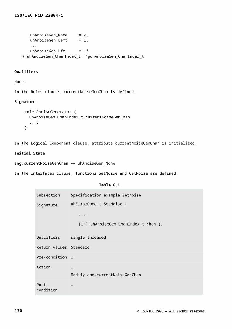
Table H.3 — Configurable Items Example
Role Attribute
AudioVolumeController minVolume
maxVolume
muteSupported
Optional features
An example is the muteSupported attribute shown in Table H.3 — Configurable Items Example. This attribute indicates whether the mute functionality is supported or not. This affects the usage of the SetMute function; if muteSupported is False, then it is not allowed to invoke the SetMute function (precondition). Such an attribute thus defines whether a feature is supported or not.
Subset of features
Next to the presence of a single feature, configuration attributes can also indicate which subset of a larger set of features is supported. Take for example an Analog Video Decoder, which supports one or more color systems out of the possibilities listed below:
typedef enum _uhVdec_ColorSystem_t { … uhVdec_ColorSystemPal = 0x00000002, uhVdec_ColorSystemSecam = 0x00000004, uhVdec_ColorSystemNtsc = 0x00000008} uhVdec_ColorSystem_t, *puhVdec_ColorSystem_t;
In this example, one platform instance may only support NTSC, whereas another platform instance may support PAL, SECAM and NTSC.
Similar to interfaces, it is possible to query at run-time for the values of the various configurable items. For this purpose, various Get functions are defined. For example, for the configurable items in Table H.3 —Configurable Items Example, the following functions are defined:
uhErrorCode_t GetVolumeRange( [out] pInt32 pMinVol, [out] pInt32 pMaxVol );uhErrorCode_t GetMuteSupported( [out] pBool pMuteSupported );
For the supported color systems, the following function is defined:
uhErrorCode_t GetSupportedColorSystems( [out] puhVdec_ColorSystemSet_t pColorSystems );
I.2.3.4 Platform Specific Interfaces
Next to the interfaces defined by the M3W API framework, a platform instance provider may add a specific interface, not defined by M3W, to a logical component when really needed. This extends the logical component. This may be necessary to be able to use some specific platform functionality (similar to what is described in I.2.2.3).
NOTE using these specific interfaces makes the client software platform instance specific, which means that one should be careful with adding such interfaces.
© ISO/IEC 2006 — All rights reserved 131
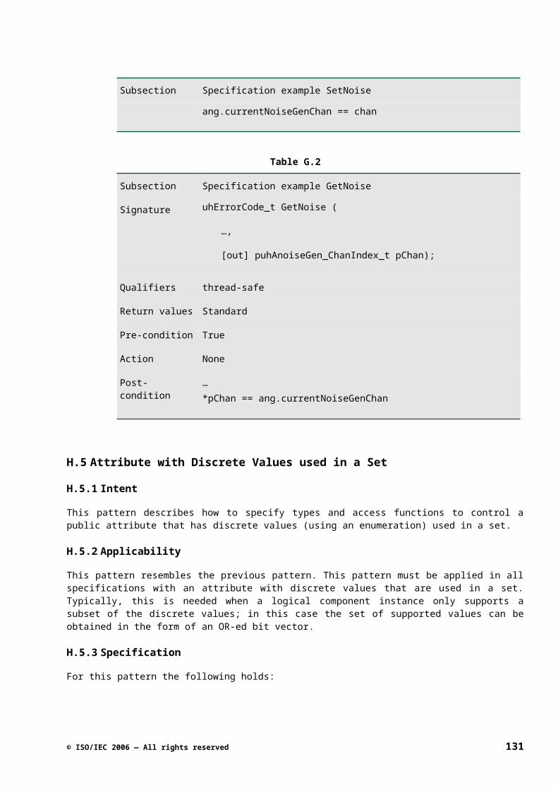
ISO/IEC FCD 23004-1
To check whether a specific interface is present, the client software can use QueryInterface.
I.2.4 Dynamic Variation
The previous sub clause dealt with static variation, i.e. the variation points are filled in when the component is instantiated. Next to that, there is also run-time variation present in the system. This variation is usually a result of the signal that flows through the platform. Based on the signal, certain functionality may be available or not.
As described in Annex H, a GetXxxAvail function can be defined as a means to check whether certain functionality is currently available or not (‘supported’ is used for static variation; ‘available’ for dynamic variation).
For example, the hue functionality in the Analog Video Decoder is in principle only useful if the signal is NTSC. Therefore, if the signal is PAL, it has been defined that the function SetHue will have no effect on the signal. To check whether the hue functionality is available, a function GetHueAvail has been defined. With dynamic variation, the reason why functionality is not available is always returned to a client, such that it can make a good decision on how to proceed.
I.3 Variation over Time
I.3.1 Introduction
The previous clause described variation in space, i.e. the variation options for a specific version of the UHAPI specification. This clause addresses variation over time, i.e. the variation caused by the evolution of the UHAPI specification.
I.3.2 Evolving the API Framework
In the Evolution Rules annex (Annex B), the lifecycle of logical components and interfaces are described. New logical components and interfaces are introduced because the related functionality is currently not present, or because the existing functionality is enhanced. Existing logical components and interfaces are removed when their functionality has become obsolete, e.g. because a new logical component is introduced with enhanced functionality supporting new requirements.
When a new logical component or interface is introduced that supports similar functionality as an existing logical component or interface, then the existing API element is not removed at once. For example, for a logical component LogCompA, a variant is made called LogCompA2. Consequently, two variants of the same functionality can be present at the same time. It is up to the platform instance to decide which variant to support (including possibly both for some transition time).
Next to variants, also versions over time exist. For example, when a new optional interface is added to a logical component, this results in a new version of the logical component (which replaces the old version). Note that such an introduction does not break any existing client code.
These changes, which take place over time, can be managed via the mechanisms described in the previous clause. Via QueryInterface, the client software can check whether an old interface is still present or already removed, or whether a new interface is already present. And, based on the platform documentation, it should be clear which logical components are used in the use cases.
In sub-clause I.1.4, it is already described that the variation in the API affects the way the middleware is structured. The variation described in this clause also affects the middleware. For example, when a new version of a logical component has a new (optional) interface, the middleware can already contain code that first checks for the presence of the new interface and that then uses it, if the new interface is available.
132 © ISO/IEC 2006 — All rights reserved
Annex J(informative)
API Qualifiers
J.1Type & Constant Qualifiers
Table I.1
Qualifier Description
error-codes Indicates that this is the definition of a group of constants that act as error codes.
enum-element Indicates that this is the definition of an enumerated type whose values represent elements of sets. The values of this type are powers of two (flags) and can be used for constructing sets by means of logical OR-ing.
enum-set Indicates that this is the definition of a type whose values represent sets of enumerated values (bitvectors). This type is typedef-ed as UInt32.
J.2Role Qualifiers
Table I.2
Qualifier Description
Root Indicates that this is the root role of the logical component. When querying the connection manager in a platform instance for an instance of this component, it will return a pointer to one of the interfaces provided by this role (provided an instance of this component exists in the current use case).
actor Indicates that the active behavior of the role consists of providing stimuli only, i.e. of calling functions, without any a priori assumptions on when these calls occur. Typical examples are roles that model clients of control interfaces. Roles of this type typically have no attributes and no streaming behavior. The streaming and active behavior are omitted in the specification.
© ISO/IEC 2006 — All rights reserved 133
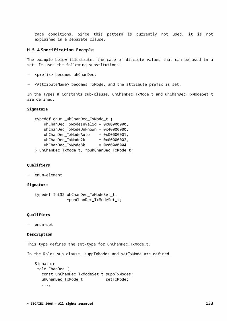
ISO/IEC FCD 23004-1
J.3Interface Qualifiers
Table I.3
Qualifier Description
callback Indicates that all functions in the interface are callback functions, typically notification functions. The difference between a callback function and a normal function is that the API specification does not specify what the effect should be of the function (this is up to the client implementing the interface) but only specifies when and with what parameters the function is called. Callback functions usually return no values and have in-parameters only.
model-interface Indicates that this is an interface introduced for modeling purposes only. The interface does not occur in the IDL of the API.
J.4Function Qualifiers
Table I.4
Qualifier Description
synchronous Indicates that the effect of the function will have been completed on returning from the function.
asynchronous Indicates that the effect of the function will not have been completed when returning from the function; the function has a delayed effect. Completion is usually reported by means of a notification.
thread-safe Indicates that the function may be accessed concurrently by multiple threads.
single-threaded Indicates that the function may be accessed by at most one thread at a time.
subscribe-function Indicates that this is a standard Subscribe function as specified in the Notification API specification. Only the signature of the function is given.
unsubscribe-function Indicates that this is a standard Unsubscribe function as specified in the Notification API specification. Only the signature of the function is given.
onsubscriptionchanged-function
Indicates that this is a standard OnSubscriptionChanged function as specified in the Notification API specification. Only the signature of the function is given.
model-function Indicates that this is a function introduced for modeling purposes only. The function does not occur in the IDL of the API.
134 © ISO/IEC 2006 — All rights reserved
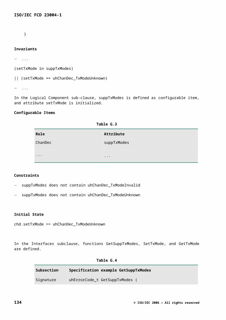
Annex K(informative)
Name Abbreviations Guide
This annex gives an overview of words and their abbreviations commonly used in names. This overview will help to avoid more than one abbreviation for the same word in order to guard consistency and readability. To limit the size of the list it only contains the less obvious abbreviations used within existing interface suite specifications.
Table J.1
Word Abbreviation
A Actual Act
Analog Ana
Audio-Decoder Adec
Audio-Video Av
Automatic Auto
B Bandwidth Bw
Background Bg
Black-Bar Bbar
Brightness-Contrast-Saturation
Bcs
Buffer Buf
C Coefficient Coef
Channel Chan
Chrominance Chroma
Closed-Caption Cc
Color Col
© ISO/IEC 2006 — All rights reserved 135
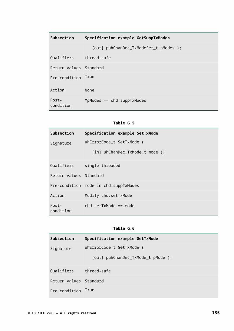
ISO/IEC FCD 23004-1
Word Abbreviation
Combination Comb
Configuration Config
Connection Conn
Contrast Contr
Control Ctrl
Converter Conv
Count Cnt
Current Curr
D Decoder Dec
Demodulator Demod
Demultiplexer Demux
Detector Det
Digital Dig
Dynamic Dyn
E Encoder Enc
Enhancement Enh
Encryption Encrypt
Error Err
Estimate Est
Expired Exp
Extractor Extr
136 © ISO/IEC 2006 — All rights reserved
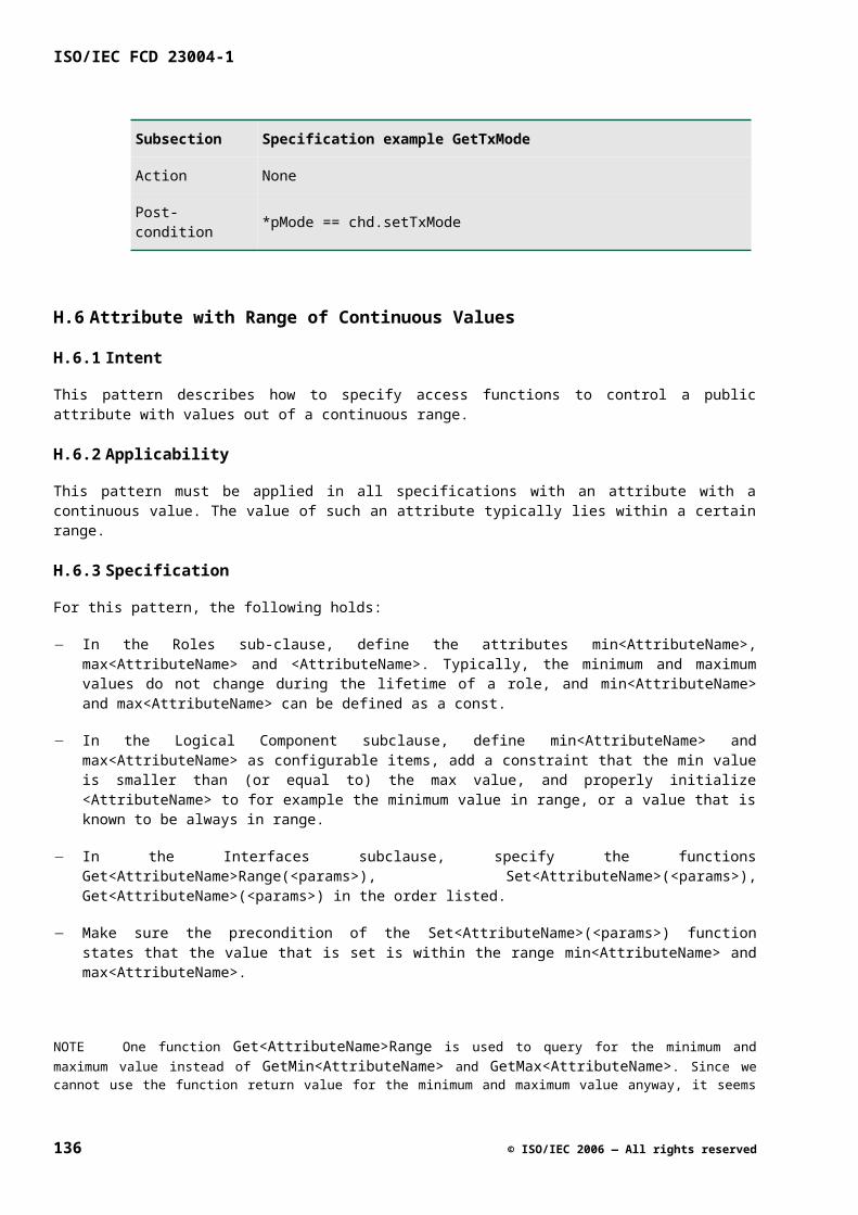
Word Abbreviation
F Feature Feat
Format Fmt
Frequency Freq
G Graphics Gfx
H Hard-Disk Hdd
High-Frequency Hf
Horizontal Hor
Hybrid Hyb
I Identification Id
Intermediate-Frequency If
L Liquid-Crystal-Display Lcd
Lookup-Table Lut
Low-Frequency Lf
Luminance Luma
M Management Mngt
Manager Mgr
Maximum Max
Measurement Meas
Message Msg
Minimum Min
Mixer Mix
© ISO/IEC 2006 — All rights reserved 137
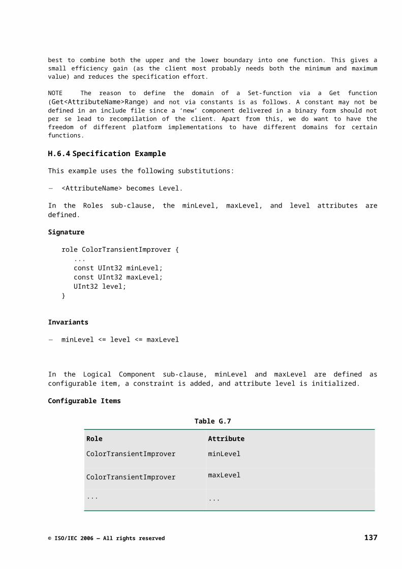
ISO/IEC FCD 23004-1
Word Abbreviation
Modulator Mod
Multiplexer Mux
N Notify Ntf
Number Nr
O Out-of-band Oob
P Parameter Param
Pixel Pix
Point-of-Deployment Pod
Position Pos
Preference Pref
Property Prop
R Radio-Frequency Rf
Rectangle Rect
Resolution Res
Red-Green-Blue Rgb
S Satellite Sat
Saturation Sat
Source Src
Supported Supp
Synchronization Sync
System-Clock-Reference Scr
138 © ISO/IEC 2006 — All rights reserved

Word Abbreviation
T Teletext Txt
Terrestrial Ter
Transport-Packet Tp
Transport-Stream Ts
V Vertical Vert
Vertical-Blanking-Interval Vbi
Video Vid
Video-Decoder Vdec
© ISO/IEC 2006 — All rights reserved 139
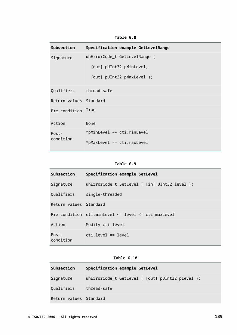
ISO/IEC FCD 23004-1
Annex L(informative)
IDL
L.1 Introduction
In this standard two IDLs are used. One IDL is used for the specification of the M3W API. The other IDL is used in the realization technology. The things that can be expressed in IDL used to specify the M3W API can also be expressed in the IDL used in the realization technology.
NOTE In the API specification IDL it is possible to specify an operation that does not return a return code (like uhErrorCode_t). The realization technology assumes that all operations have such a return code. To deal with the exception that an operation does not have a return code (like for example in notification interfaces) an attribute for an operation is introduced ([NO RESULT]);
L.2 IDL used in M3W API specification
L.2.1 GLOBAL
datadef_idl : (datadef_stm)+ EOF
intfdef_idl : (intfdef_stm)+ EOF
compdef_idl : (compdef_stm)+ EOF
allfile : (all_stm)+ EOF
all_stm : import_stm | const_stm | typedef_stm | intf_fw_dcl
| interface_dcl | coclass_dcl | library_dcl
datadef_stm : import_stm | const_stm | typedef_stm
const_stm : "const" (type) IDENT EQUAL (~SEMI)+ SEMI
import_stm : "import" STRING SEMI |
LBRACK "extern" RBRACK "import" STRING SEMI
L.2.2 TYPES
typedef_stm : "typedef" type aliases SEMI
aliases : (alias) (COMMA alias)*
alias : (is_pointer)? IDENT (is_array)? |
(is_pointer)? "Void"
140 © ISO/IEC 2006 — All rights reserved
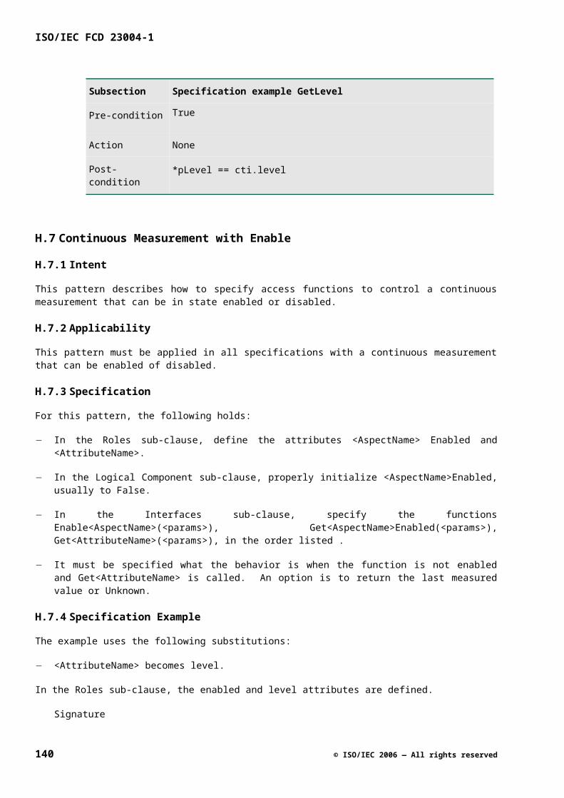
type : mystruct | myenum | myunion | (is_const)? basic
subtype : (myint | userdefined)
mystruct : (is_const)? "struct" (tag)? LCURLY (structfield)
+ RCURLY
structfield : (type (is_pointer)? IDENT (is_array)? SEMI)
| ((subtype) IDENT (bitfield) SEMI)
bitfield : COLON INT
myenum :(is_const)? "enum" (tag)? LCURLY (enumelement)
(COMMA enumelement)* RCURLY
enumelement : IDENT (EQUAL (INT | HEX | NEGINT))?
myunion : (is_const)? "union" (tag)? LCURLY (unionfield)+
RCURLY
unionfield : (type (is_pointer)? IDENT (is_array)? SEMI)
basic : myint | myshort | mylong | mychar | mydouble |
myfloat | myvoid | userdefined
myshort : ("signed" | "unsigned")? "short" ("int")?
mylong : ("signed" | "unsigned")? "long" ("int")?
myint : ("signed" | "unsigned")? "int"
mychar : ("signed" | "unsigned")? "char"
mydouble : ("long")? "double"
myfloat : "float"
myvoid : "void" | "Void"
userdefined : IDENT
tag : IDENT
L.2.3 INTERFACES
intfdef_stm : const_stm | import_stm | typedef_stm | intf_fw_dcl
| interface_dcl
intf_fw_dcl : "interface" IDENT SEMI
© ISO/IEC 2006 — All rights reserved 141
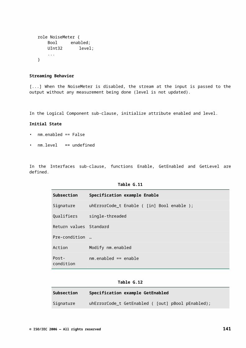
ISO/IEC FCD 23004-1
interface_dcl : (intf_attributes)? "interface"
IDENT (parent_intf)? LCURLY
(interface_body) RCURLY ;
parent_intf : COLON IDENT (COMMA IDENT)*
interface_body : (method | typedef_stm | intf_fw_dcl)*
method : (meth_attributes)? meth_return_type IDENT
LPAREN (parameters) RPAREN SEMI
meth_return_type : type (is_pointer)?
par_type : type (is_pointer)?
parameters : ((parameter) (COMMA parameter)*)? |
"Void" | "void"
parameter : par_attributes par_type IDENT (is_array)?
L.2.4 ATTRIBUTES
intf_attributes : LBRACK intf_attribute
( COMMA intf_attribute)* RBRACK
intf_attribute : "version" LPAREN REAL RPAREN
| "uuid" LPAREN GUID RPAREN
| "object"
| "local"
meth_attributes : LBRACK meth_attribute
( COMMA meth_attribute)* RBRACK
meth_attribute : "async" | "local"
par_attributes : LBRACK par_attribute
( COMMA par_attribute)* RBRACK
par_attribute : "in"
| "out"
| "iid_is" LPAREN IDENT RPAREN
| "string"
142 © ISO/IEC 2006 — All rights reserved
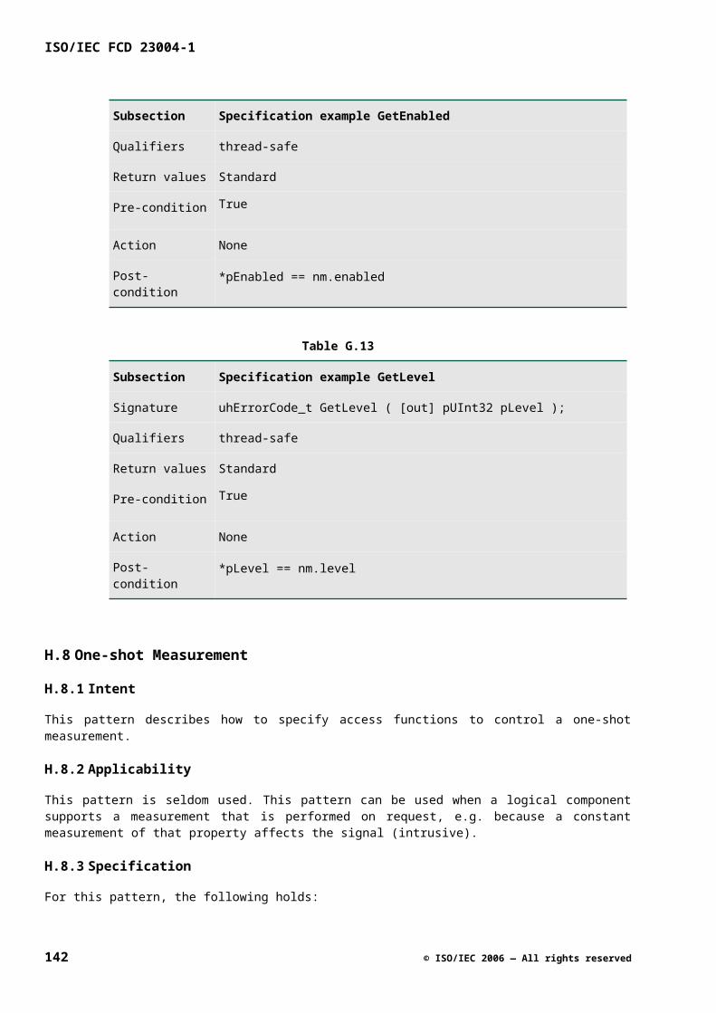
| "size_is" LPAREN (IDENT | INT) RPAREN
ccl_attributes : LBRACK ccl_attribute
( COMMA ccl_attribute)* RBRACK
ccl_attribute : "uuid" LPAREN GUID RPAREN
| "singleton"
| "version" LPAREN REAL RPAREN
| "helpstring" LPAREN STRING RPAREN
ifw_attributes : LBRACK ifw_attribute
( COMMA ifw_attribute)* RBRACK
ifw_attribute : "default"
L.2.5 TYPE MODIFIERS
is_pointer : (STAR)+ (is_const)?
is_array : LBRACK (INT | IDENT)? RBRACK
is_const : "const"
L.2.6 COMPONENT DEFINITION IDL
compdef_stm : const_stm | import_stm | typedef_stm | coclass_dcl |
library_dcl
coclass_dcl : (ccl_attributes)? "coclass" IDENT \
LCURLY (coclass_intf)+ RCURLY
coclass_intf : (ifw_attributes)? "interface" IDENT SEMI
library_dcl : (ccl_attributes)? "library" IDENT
LCURLY library_body RCURLY
library_body : (coclass_dcl | intf_fw_dcl)*
vnumber : REAL
uuidnumber : GUID
field : IDENT IDENT
© ISO/IEC 2006 — All rights reserved 143
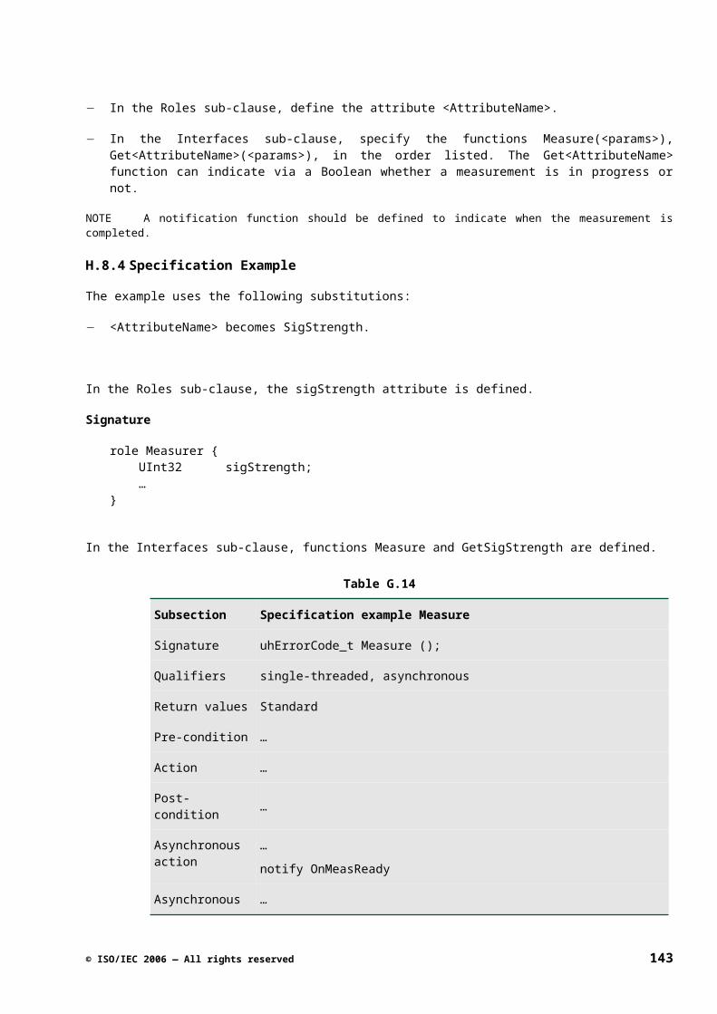
ISO/IEC FCD 23004-1
L.2.7 TOKENS
OCTDIGIT : '0'..'7'
HEXDIGIT : ('0'..'9' | 'a'..'f' | 'A'..'F')
HEX : ("0x" | "0X") (HEXDIGIT)+
GUID : (HEXDIGIT)(HEXDIGIT)(HEXDIGIT)(HEXDIGIT)
(HEXDIGIT)(HEXDIGIT)(HEXDIGIT)(HEXDIGIT)'-'
(HEXDIGIT)(HEXDIGIT)(HEXDIGIT)(HEXDIGIT)'-'
(HEXDIGIT)(HEXDIGIT)(HEXDIGIT)(HEXDIGIT)'-'
(HEXDIGIT)(HEXDIGIT)(HEXDIGIT)(HEXDIGIT)'-'
(HEXDIGIT)(HEXDIGIT)(HEXDIGIT)(HEXDIGIT)
(HEXDIGIT)(HEXDIGIT)(HEXDIGIT)(HEXDIGIT)
(HEXDIGIT)(HEXDIGIT)(HEXDIGIT)(HEXDIGIT)
ESC : '\\' ('n' |'t' | 'v' | 'b' | 'r' | 'f' | 'a'|
'\\' | '?' | '\'' | '"')
DIGIT : '0'..'9'
INT : (DIGIT)+
REAL : INT '.' INT
NEGINT : '-' (DIGIT)+
INT_OR_REAL : REAL | INT
EQUAL : '='
OR : '|'
MINUS : '-'
PLUS : '+'
DIV : '/'
EXCL : '!'
GREATER : '>'
SMALLER : '<'
LPAREN : '('
144 © ISO/IEC 2006 — All rights reserved
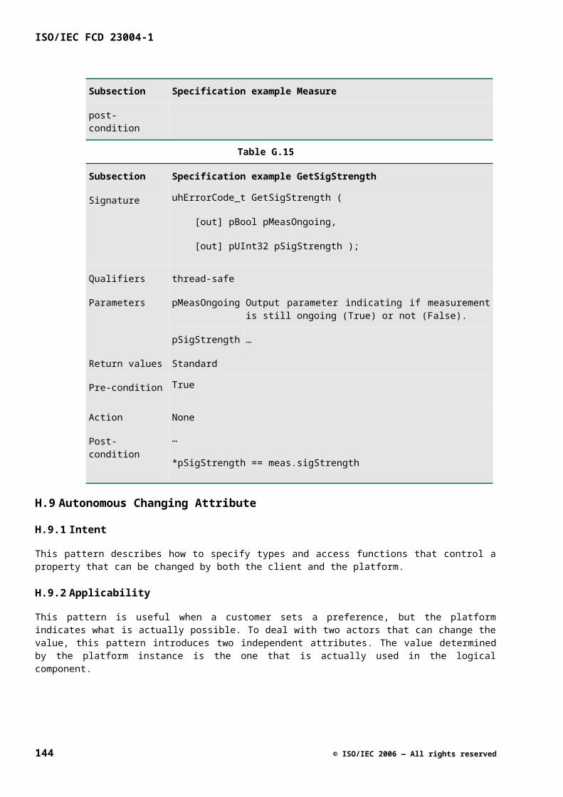
RPAREN : ')'
COMMA : ','
LCURLY : '{'
RCURLY : '}'
LBRACK : '['
RBRACK : ']'
DOT : '.'
IDENT : ('a'..'z'|'A'..'Z'|'_')
('a'..'z'|'A'..'Z'|'_'|'0'..'9')*
WS : (' ' | '\t' | '\n' | '\r')
COLON : ':'
AMPERS : '&'
STAR : '*'
HASH : '#'
SEMI : ';'
PERCENT : '%'
SL_COMMENT : "//" (~'\n')* '\n'
ML_COMMENT : "/*" ( '\n' | ('*')+ ( '\n' | ~('*' | '/' | '\n'))
| ~('*' | '\n'))* "*/"
STRING : '"' (ESC|~'"')* '"'
L.3 IDL used in M3W realization technology
specification : <definition>*
definition : <type_dcl> “;” |
<const_dcl> “;” |
<interface_dcl> “;” |
<library_dcl> “;" |
© ISO/IEC 2006 — All rights reserved 145
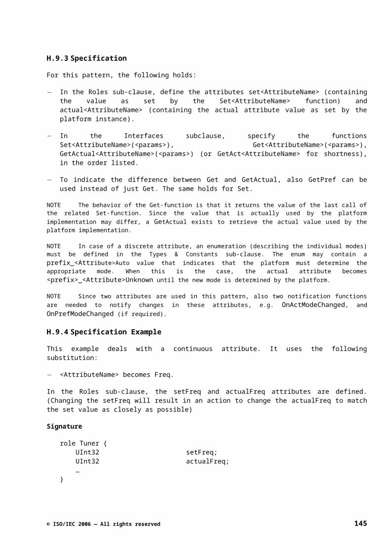
ISO/IEC FCD 23004-1
<exception_dcl> “;” |
<forward_dcl> “;” |
<rename_dcl> “;” |
<namespace_dcl> “;” |
<service_dcl> “;” |
<component_dcl> “;”
namespace_dcl : “namespace” <scoped_name> “{“ <definition>* “}”
forward_dcl : “interface” <scope_name> |
“exception” <identifier> |
“struct” <identifier> |
“union” <identifier> |
“namespace” <scope_name> |
“service” <scope_name> |
“component” <scope_name>
rename_dcl : “interface” <identifier> “=“ <scoped_name> |
“namespace” <identifier> “=“ <scoped_name> |
“service” <identifier> “=“ <scoped_name> |
“component” <identifier> “=“ <scoped_name>
interface_dcl : “interface” <scope_name> [“:” <scoped_name>]
“{“ <op_dcl>+ “}”
const_dcl : “const” <const_type> <identifier> “=“ <const_exp>
const_type : <integer_type> |
<char_type> |
<boolean_type> |
<floating_pt_type> |
<string_type> |
<scoped_name>
const_exp : <or_expr>
or_expr : <xor_expr> |
146 © ISO/IEC 2006 — All rights reserved
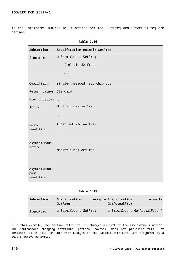
<or_expr> “|” <xor_expr>
xor_expr : <and_expr> |
<xor_expr> “^” <and_expr>
and_expr : <shift_expr> |
<and_expr> “&” <shift_expr>
shift_expr : <add_expr> |
<shift_expr> (“<<” | “>>”) <add_expr>
add_expr : <mult_expr> |
<add_expr> (“+”|”-“) <mult_expr>
mult_expr : <unary_expr> |
<mult_expr> (“*”|”/”|”%”) <unary_expr>
unary_expr : [(“-“|”+”|”~”)] <primary_expr>
primary_expr : <scoped_name> |
<literal> | “(“ <const_exp> “)”
literal : INTEGER_LITERAL |
STRING_LITERAL |
CHARACTER_LITERAL |
FLOATING_PT_LITERAL |
<boolean_literal>
boolean_literal : “True” | “False”
positive_int_const : <const_exp>
type_dcl : “typedef” <type_declarator> |
<struct_type> |
<union_type> |
<enum_type>
type_declarator : <type_spec> <declarators>
type_spec : <simple_type_spec> |
<constr_type_spec>
simple_type_spec : <base_type_spec> |
© ISO/IEC 2006 — All rights reserved 147
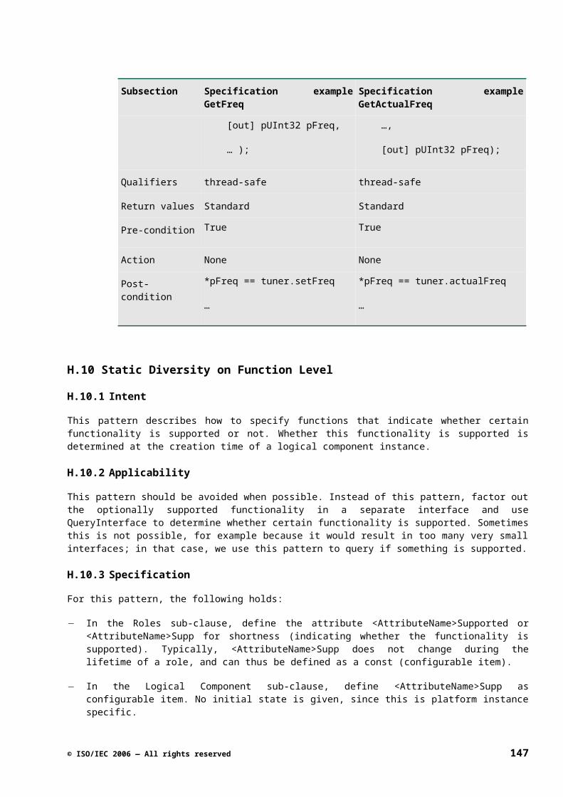
ISO/IEC FCD 23004-1
<template_type_spec> |
<scoped_name>
base_type_spec : <floating_pt_type> |
<integer_type> |
“Char” |
“Bool” |
“pIUnknown” |
“pVoid” |
“UUID”
template_type_spec : <sequence_type> |
<string_type>
constr_type_spec : <struct_type> |
<union_type> |
<enum_type>
Declarators : <declarator> |
<declarators> “,” <declarator>
declarator : <identifier> |
<declarator> “[“ <positive_int_const> “]”
floating_pt_type : “Float” | “Double”
integer_type : “Int8” | “Int16” | “Int32” | “UInt8” |
“UInt16” | “UInt32” |
struct_type : “struct” <identifier> “{“ <member>+ “}”
member : <type_spec> <declarators> “;”
union_type : “union” <identifier>
“switch” “(“ <switch_type_spec> “)”
“{“ <switch_body> “}”
switch_type_spec : <integer_type> | “Char” | “Bool” | <enum_type> |
<scoped_name>
switch_body : (<case_label> <type_spec> <declarator> “;”)+
148 © ISO/IEC 2006 — All rights reserved
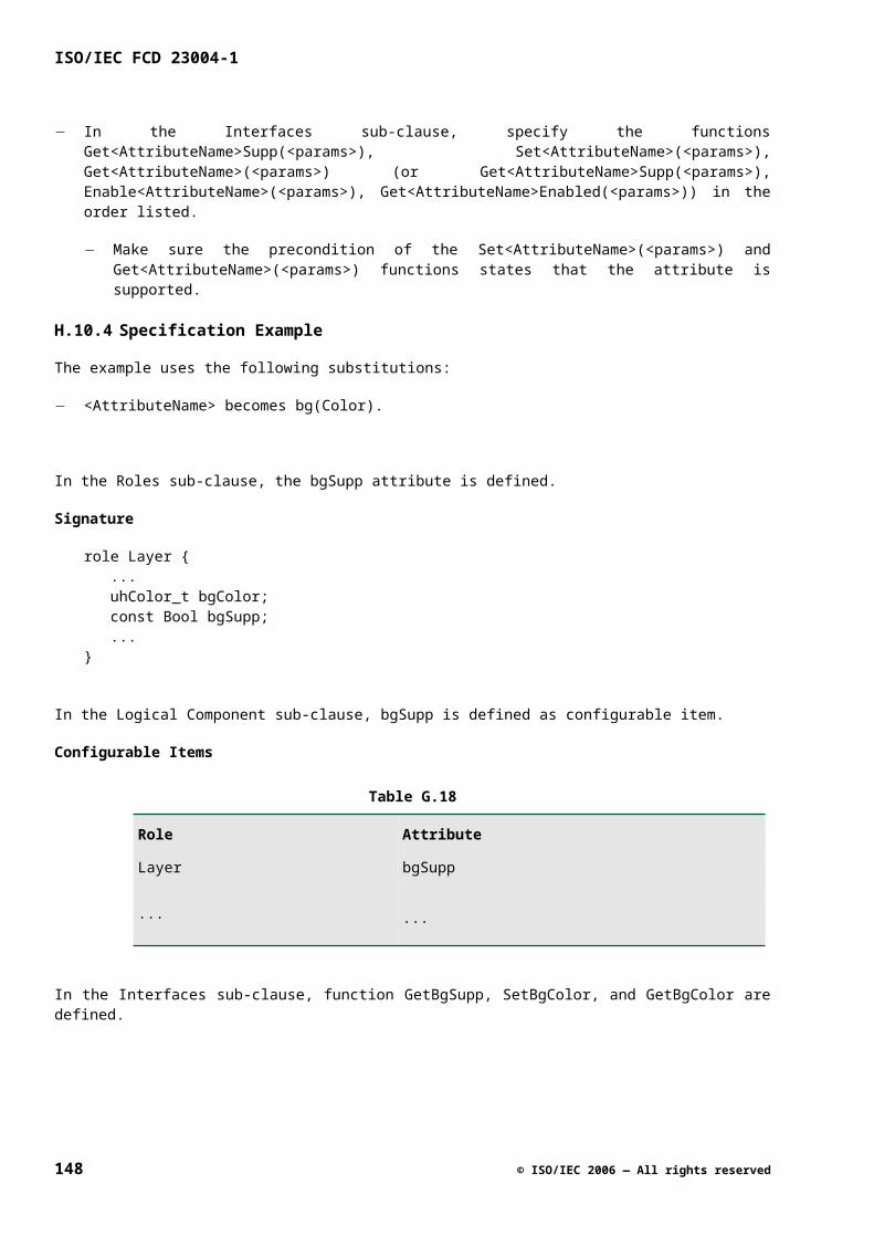
case_label : (“case” <const_exp> | “default”) “:”
enum_type : “enum” <identifier> “{“ <enumerator>+ “}”
enumerator : <identifier>
sequence_type : “sequence” “<” <simple_type_spec>
[“,” <positive_int_const>] “>”
string_type : “String” [“<“ positive_int_const “>“]
exception_dcl : “exception” <identifier>
[“:” <scoped_name>] “{“ <member>* “}”
op_dcl : <op_type_spec> [ op_attr ] <identifier>
“(“ [<param_dcls>] “)”
[ “raises” <identified_name_list>]
op_attr : "[" STRING_LITERAL "]"
param_dcls : <param_dcl> | <param_dcls> “,” <param_dcl>
param_dcl : (“in” | “inout” | “out”)
<param_type_spec> <identifier>
op_type_spec : “Void” | <param_type_spec>
param_type_spec : <base_type_spec> | <string_type> | <scoped_name>
identified_name_list : <identified_name> ["=" INTEGER_LITERAL] |
<identified_name_list> “,”
<identified_name>
service_dcl : “service” <scoped_name> [“:” <scoped_name>]
[“implements” <scoped_name_list> ]
[“manager” <guid>] “{“ <service_element>* “}”
service_element : <port_attribute> “{“ <port_declarator>+ “}” “;” |
<port_attribute> <port_declarator> “;” |
“attributes” “{“ <attribute>+ “}” “;”
attribute : [ (“readonly” | ”writeonly”)]
<param_type_spec> <declarators> “;”
port_attribute : “provides” | ”uses”
© ISO/IEC 2006 — All rights reserved 149
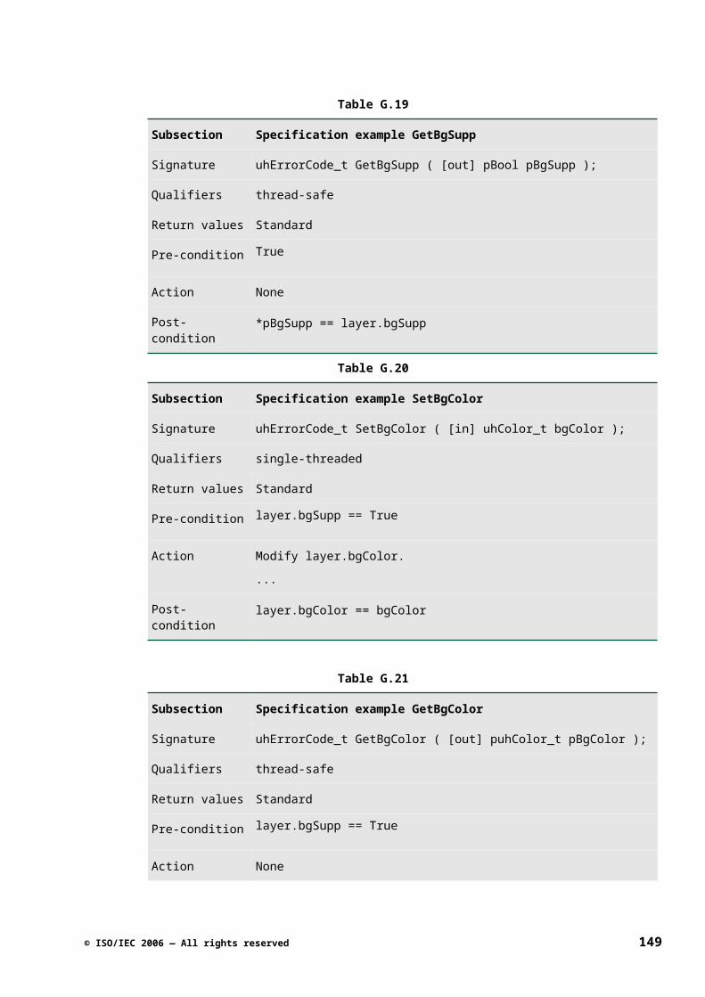
ISO/IEC FCD 23004-1
| requires”[“<” <port_int_const> “,”
<port_int_const> “>”]
port_declarator : <scoped_name> <identifier> “;”
port_int_const : “*” |<positive_int_const>
scoped_name_list : <scoped_name> | <scoped_name_list> “,”
<scoped_name>
component_dcl : “component” <scoped_name>
[“complies” <scoped_name_list>]
“{“ <component_element>* “}”
component_element: ( “provides” | ”contains” )
<scoped_name_list> “;”
150 © ISO/IEC 2006 — All rights reserved
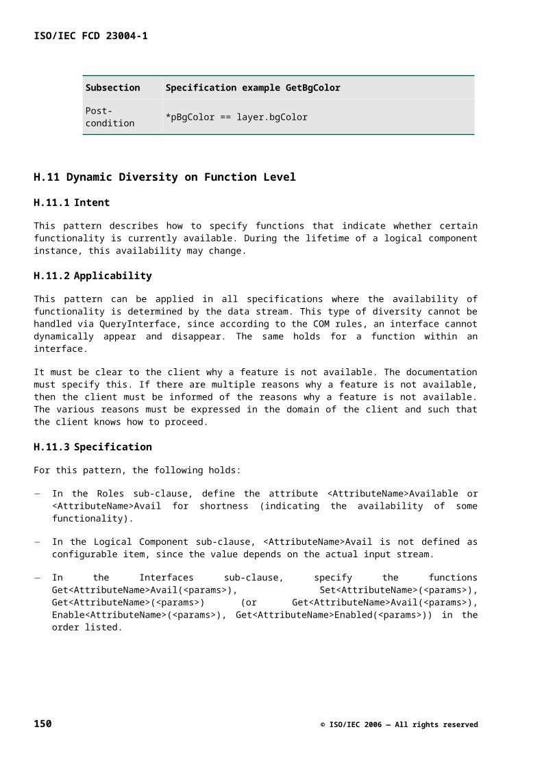
Bibliography
[1] ISO/IEC Directives, Part 2, Rules for the structure and drafting of International Standards, 2001
[2] ISO/IEC TR 10000-1, Information technology — Framework and taxonomy of International Standardized Profiles — Part 1: General principles and documentation framework
[3] ISO 10241, International terminology standards — Preparation and layout
[4] ISO 128-30, Technical drawings — General principles of presentation — Part 30: Basic conventions for views
[5] ISO 128-34, Technical drawings — General principles of presentation — Part 34: Views on mechanical engineering drawings
[6] ISO 128-40, Technical drawings — General principles of presentation — Part 40: Basic conventions for cuts and sections
[7] ISO 128-44, Technical drawings — General principles of presentation — Part 44: Sections on mechanical engineering drawings
[8] ISO 31 (all parts), Quantities and units
[9] IEC 60027 (all parts), Letter symbols to be used in electrical technology
[10] ISO 1000, SI units and recommendations for the use of their multiples and of certain other units
[11] ISO 690, Documentation — Bibliographic references — Content, form and structure
[12] ISO 690-2, Information and documentation — Bibliographic references — Part 2: Electronic documents or parts thereof
[13]Dale Rogerson, Inside COM - Microsoft’s Component Object Model, Microsoft Press, ISBN: 1-57231-349-8.
[14]Design Patterns: Elements of Reusable Object-Oriented Software, E. Gamma, R. Helm, R. Johnson, and J. Vlissides, Addison-Wesley (1995).
© ISO/IEC 2006 — All rights reserved 151