Embed Size (px)
Citation preview
Accepted Manuscript
Isogeometric analysis of functionally graded plates using a refined plate theory
H. Nguyen-Xuan, Loc V. Tran, Chien H. Thai, S. Kulasegaram, S.P.A. Bordas
PII: S1359-8368(14)00144-9
DOI: http://dx.doi.org/10.1016/j.compositesb.2014.04.001
Reference: JCOMB 2986
To appear in: Composites: Part B
Received Date: 22 August 2013
Revised Date: 24 March 2014
Accepted Date: 2 April 2014
Please cite this article as: Nguyen-Xuan, H., Tran, L.V., Thai, C.H., Kulasegaram, S., Bordas, S.P.A., Isogeometric
analysis of functionally graded plates using a refined plate theory, Composites: Part B (2014), doi: http://dx.doi.org/
10.1016/j.compositesb.2014.04.001
This is a PDF file of an unedited manuscript that has been accepted for publication. As a service to our customers
we are providing this early version of the manuscript. The manuscript will undergo copyediting, typesetting, and
review of the resulting proof before it is published in its final form. Please note that during the production process
errors may be discovered which could affect the content, and all legal disclaimers that apply to the journal pertain.
1
Isogeometric analysis of functionally graded plates using a refined plate
theory
H. Nguyen-Xuan1*
1Department of Mechanics, Faculty of Mathematics & Computer Science, University of Science, VNU-HCMC, 227 Nguyen Van Cu Street, District 5, Ho Chi Minh City 700000,Vietnam
, Loc V. Tran2,3, Chien H. Thai2, S. Kulasegaram4, S.P.A. Bordas5
2Division of Computational Mechanics, Ton DucThang University Ho Chi Minh City, Vietnam3Department of Architectural Engineering, SejongUnviersity, 98 Kunja Dong, Kwangjin Ku, Seoul,
143-747, South Korea4Institute of Mechanics and Advanced Materials, School of Engineering, Cardiff University, Queen’s
Buildings, The Parade, Cardiff CF24 3AA, UK5Université du Luxembourg, Faculté des Sciences, de la Technologies et de la Communication, Campus
Kirchberg, 6, rue Coudenhove-Kalergi, L-1359, Luxembourg
Abstract
We present in this paper a simple and effective approach that incorporates isogeometric finite element
analysis (IGA) with a refined plate theory (RPT) for static, free vibration and buckling analysis of
functionally graded material (FGM) plates. A new inverse tangent distributed function through the plate
thickness is proposed. The RPT enables us to describe the non-linear distribution of shear stresses
through the plate thickness without any requirement of shear correction factors (SCF). IGA utilizes
basis functions namely B-splines or non-uniform rational B-splines (NURBS) which reach easily the
smoothness of any arbitrary order. It hence satisfies the C1 requirement of the RPT model. The present
method approximates the displacement field of four degrees of freedom per each control point and
retains the computational efficiency while ensuring the high accuracy in solution.
Keywords: A. Plates; B. Buckling; B. Vibration; C. Computational modeling; FGM
*Corresponding author. Email address: [email protected] (H. Nguyen-Xuan)
2
1. Introduction
FGM-a mixture of two distinct material phases: ceramic and metal are very well capable of reducing
thermal stresses, resisting high temperature environment and corrosion coatings. FG structures are
therefore suitable for applications in aerospace structures, nuclear plants and semiconductor
technologies.
Besides the extensive application of FG plates in engineering structures, a lot of plate theories have
been developed to analyze the thermo-mechanical behavior of such structures. The classical plate
theory (CPT) relied on the Kirchoff -Love assumptions merely to provide acceptable results for the thin
plate. The first order shear deformation theory (FSDT) based on Reissner [1] and Mindlin [2], which
takes into account the shear effect, was therefore developed. In FSDT-based finite element models, it is
necessary to use some improved techniques such as reduced integration (RI) [3], mixed interpolation of
tensorial components (MITC) [4], Mindlin-type plate element with improved transverse shear (MIN)
[5], discrete shear gap (DSG) [6-9] elements, etc, to overcome the shear locking phenomenon. In
addition, with the linear in-plane displacement assumption through plate thickness, shear strain/stress
obtained from FSDT distributes inaccurately and does not satisfy the traction free boundary conditions
at the plate surfaces. The shear correction factors (SCF) are hence added to fix the unrealistic shear
strain energy part. The values of SCF are quite dispersed through each problem and may be difficult to
determine [10]. To ensure the curved distribution of shear stress, various kinds of higher order shear
deformable theory (HSDT), which include higher-order terms in the approximation of the displacement
field, have then been devised such as third order shear deformation theory (TSDT) [11,12],
trigonometric shear deformation theory [13-17], exponential shear deformation theory [18-20], refined
plate theory (RPT) based on two unknown functions of transverse deflection [21-25] and so on. The
RPT model was proposed by Senthilnathanet al. [21] with one variable lower than the TSDT model,
and was then developed by Shimpiet al. [26-28] using only two unknown variables for isotropic and
orthotropic plates. It is worthwhile mentioning that the HSDT models provide better results and yield
more accurate and stable solutions (e.g. inter-laminar stresses and displacements) [29,30] than the
FSDT ones without requirement the SCF. Nevertheless, the HSDT requires the C1-continuity of
generalized displacement field leading to the second-order derivative of the stiffness formulation and it
causes the obstacles in the standard finite element formulations. Several C0 continuous elements [31-35]
were proposed or Hermite interpolation function with the C1-continuity was added for just specific
3
approximation of transverse displacement [11]. It may produce extra unknown variables including
derivative of deflection ,xw , , yw , ,xyw [36] which lead to increase in the computational cost. In this paper,
we show that C1-continuous elements will be easily reached by IGA without any additional variables.
Isogeometric approach (IGA) has been recently proposed by Hughes et al. [37] to integrate
Computer Aided Design (CAD) and Finite Element Analysis (FEA). The crucial idea of IGA is to use
same non-uniform rational B-Spline (NURBS) functions in describing the exact geometry of problem
and constructing finite approximation for analysis. Using NURBS functions allows us to manipulate
easily refinement, de-refinement and degree elevation [38]. In addition, the higher order smoothness of
NURBS basis functions can be achieved easily. Hence, IGA naturally verifies the C1-continuity of
plates based on the HSDT assumption, which is interested in this study.
In this paper, a simple and effective approach based on the framework of isogeometric analysis
(IGA) and a refined plate theory (RPT) is presented for static, free vibration and buckling analysis of
functionally graded material (FGM) plates. We also introduce a novel inverse tangent distributed
function through the plate thickness in order to enhance the accuracy of solutions following a refined
plate theory. The RPT is independent on SCF and free from shear locking. The material property
changing continuously through plate thickness is homogenized by the rule of mixture and the Mori-
Tanaka homogenization technique. IGA utilizes the NURBS functions which achieve easily the
smoothness with arbitrary continuous order. It helps the present method to naturally satisfy the C1
continuous requirement of this plate theory. Numerous numerical examples are provided to illustrate the
effectiveness of the present formulation in comparison with other published models.
The paper is outlined as follows. Next section introduces the novel formulation RPT based on IGA
for FGM plates. In section 3, the formulation of plate theory based on IGA is described. The numerical
results and discussions are provided in section 4. Finally, this article is closed with some concluding
remarks.
2. The novel refined plate theory for FGM plates
2.1. Functionally graded material
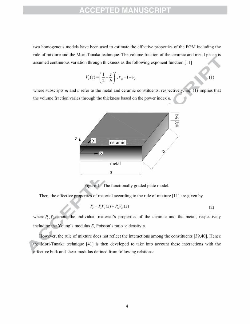
Functionally graded material is a composite material which is created by mixing two distinct material
phases which are often ceramic at the top and metal at the bottom as shown in Figure 1. In this paper,
4
two homogenous models have been used to estimate the effective properties of the FGM including the
rule of mixture and the Mori-Tanaka technique. The volume fraction of the ceramic and metal phase is
assumed continuous variation through thickness as the following exponent function [11]
1( )2
n
czV zh
, 1m cV V (1)
where subscripts m and c refer to the metal and ceramic constituents, respectively. Eq. (1) implies that
the volume fraction varies through the thickness based on the power index n.
Figure 1: The functionally graded plate model.
Then, the effective properties of material according to the rule of mixture [11] are given by
( ) ( )e c c m mP PV z P V z (2)
where ,c mP P denote the individual material’s properties of the ceramic and the metal, respectively
including the Young’s modulus E, Poisson’s ratio , density .
However, the rule of mixture does not reflect the interactions among the constituents [39,40]. Hence
the Mori-Tanaka technique [41] is then developed to take into account these interactions with the
effective bulk and shear modulus defined from following relations:
5
1
4/31
1
c m
m m
c m
m
e m cK K
c m m K
e m c
c m m f
K K VK K V
VV
(3)
where 1(9 8 )
6( 2 )m m m
m m
KfK
. Then, the effective values of Young’s modulus Ee and Poisson’s ratio e are
given by:
9 3 2,3 2(3 )
e e e ee e
e e e e
K KEK K (4)
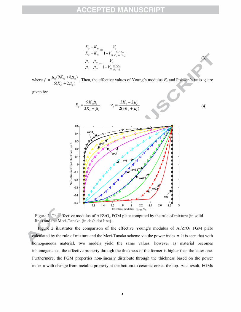
Figure 2. The effective modulus of Al/ZrO2 FGM plate computed by the rule of mixture (in solid line) and the Mori-Tanaka (in dash dot line).
Figure 2 illustrates the comparison of the effective Young’s modulus of Al/ZrO2 FGM plate
calculated by the rule of mixture and the Mori-Tanaka scheme via the power index n. It is seen that with
homogeneous material, two models yield the same values, however as material becomes
inhomogeneous, the effective property through the thickness of the former is higher than the latter one.
Furthermore, the FGM properties non-linearly distribute through the thickness based on the power
index n with change from metallic property at the bottom to ceramic one at the top. As a result, FGMs
6
can inherit the best properties of the components, e.g., low thermal conductivity, high thermal
resistance by ceramic and ductility, durability of metal. Due to their advantageous features, FGMs have
therefore received great attention by many researchers for various types of structures such as beams
[42,43], plates [44-46] and shells [47,48], etc.
2.2. The novel inverse tangent transverse shear deformation plate theory
Regarding the effect of shear deformation, the higher-order terms are taken into account the
displacement field. A popular theory based on TSDT [11] for bending plate was given as
0 ,
0 ,
0
( , , ) ( )
( , , ) ( )
( , )
x x x
y y y
u x y z u z g z w
v x y z v z g z w
w x y w
,2 2h hz (5)
where 3 2( ) 4 / 3g z z h and the variables 0 0 0Tu vu , w0and
T
x y are the membrane
displacements, the deflection of the mid-plane and the rotations in the y-z, x-z planes, respectively.
Introducing additional assumptions given in Eq. (6) following the work of Senthilnathan et al. [21], a
general displacement field based on a refined plate theory is denoted as
0 ;b s bw w w w (6)
where wb and ws are defined as the bending and shear components of deflection. Eq. (5) can be
expressed in the simpler form with four unknown variables:
0 , ,
0 ,,
( , , ) ( )( , , ) ( )
( , )
b x s x
s yb y
b s
u x y z u zw g z wv x y z v z g z w ww x y w w
(7)
Herein, the function ( ) ( )g z f z z is used to describe the distribution of the transverse shear strains
and stresses through the plate thickness. The function ( )f z is chosen to satisfy the tangential zero value
at / 2z h . It implies that traction-free boundary condition at the top and bottom plate surfaces is
automatically satisfied. Several shape functions reported in the literature [11,18,19,49,50] are listed in
Table 1. Figure 3 illustrates distribution of shape functions and their derivatives through the plate
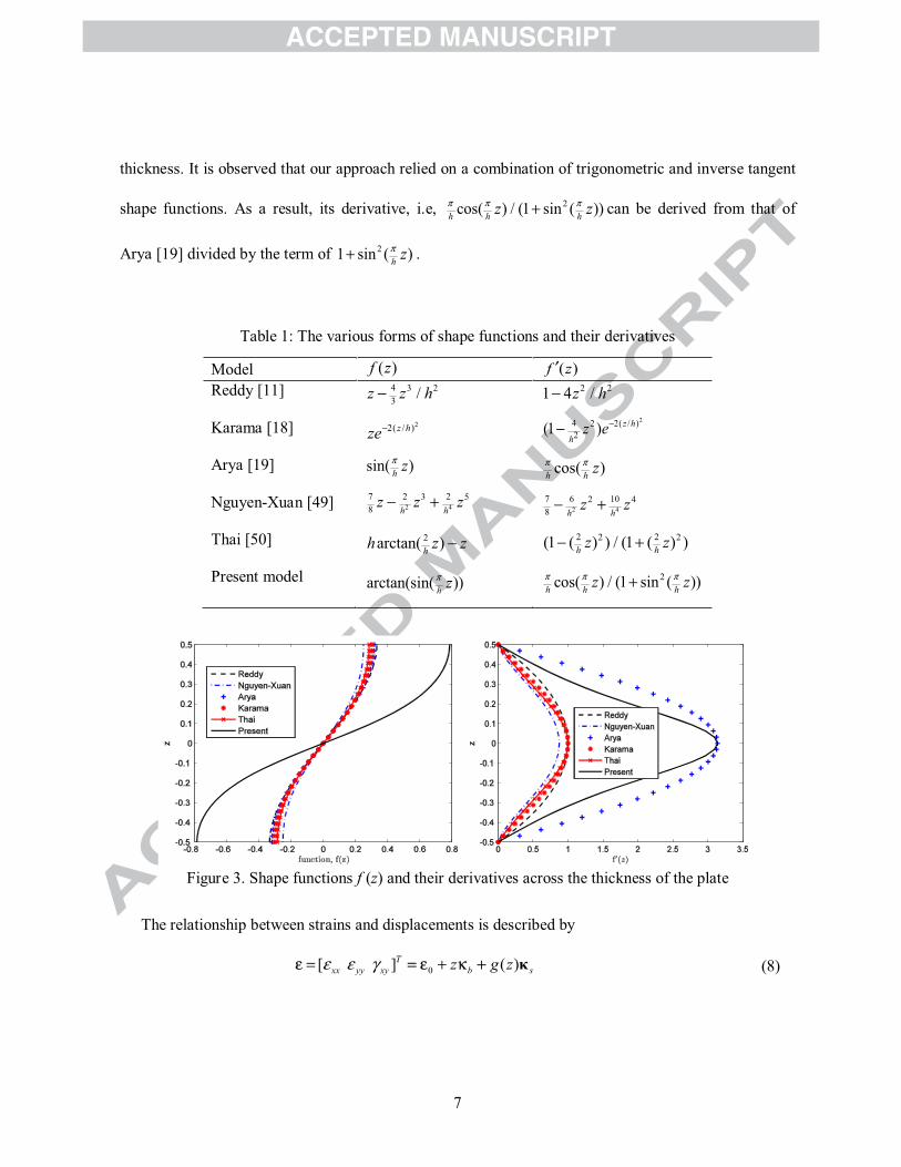
7
thickness. It is observed that our approach relied on a combination of trigonometric and inverse tangent
shape functions. As a result, its derivative, i.e, 2cos( ) / (1 sin ( ))h h hz z can be derived from that of
Arya [19] divided by the term of 21 sin ( )h z .
Table 1: The various forms of shape functions and their derivatives
Model ( )f z ( )f zReddy [11]
Karama [18]
Arya [19]
Nguyen-Xuan [49]
Thai [50]
Present model
4 3 23 /z z h
22( / )z hze
sin( )h z
2 47 2 23 58 h h
z z z
2arctan( )hh z z
arctan(sin( ))h z
2 21 4 /z h24 2 2( / )
2(1 ) z h
hz e
cos( )h h z
2 47 6 102 48 h h
z z
2 22 2(1 ( ) ) / (1 ( ) )h hz z
2cos( ) / (1 sin ( ))h h hz z
Figure 3. Shape functions f (z) and their derivatives across the thickness of the plate
The relationship between strains and displacements is described by
0[ ] ( )Txx yy xy b sz g z (8)
8
( )T
xz yz sf z
where
0,
0 0,
0, 0,
x
y
y x
uv
u v,
,
,
,2
b xx
b b yy
b xy
www
,,
,
,2
s xx
s s yy
s xy
www
, ,
,
s xs
s y
ww (9)
From Hook’s law the stresses form
, G (10)
where the material matrices are given as
2
1 01 0
10 0 (1 ) / 2
1 00 12(1 )
ee
ee
e
e
e
E
E
Q
G
(11)
The total potential energy is given by
U V (12)
where , ,U V are strain energy, work done and kinetic energy given as [51]
1 1d d2 2
T T
V VU V V
d dT TV u f u t
2 2 21 ( )d2 V
u v w V
(13)
in which andf t are the external load and prescribed traction on boundary, respectively.
9
Using the principle of virtual work [36], a weak form of the static model for the plates under
transverse loading q0 can be briefly expressed as:
0d d dT b T s wqD D (14)
where
b
A B ED = B D F
E F H
/2 2 2
/2, , , , , (1, , , ( ), ( ), ( )) d
h
ij ij ij ij ij ij ijhA B D E F H z z g z zg z g z Q z
/2 2
/2( ) d
hsij ijh
D f z G z
(15)
For the free vibration analysis of the plates, weak form can be derived from the following dynamic
equation
d d dT b T s TD D u mu (16)
wherem - the mass matrix is calculated according to the consistent form
0 00 00 0
0
0
0
Im I
Iwhere
1 2 4
2 3 5
4 5 6
I I II I II I I
0I (17)
/22 2
1 2 3 4 5 6/2
, , , , , ( ) 1, , , ( ), ( ), ( ) dh
h
I I I I I I z z z g z zg z g z z . (18)
and
1 0 0
2 1 , 2 , 3
, ,3
, ; ; 00
b x b y
s x s y
u v ww w
w w
uu u u u u
u(19)
For the buckling analysis, a weak form of the plate under the in-plane forces can be expressed as:
0d d d 0T b T s T w wD D N (20)
10
where [ / / ]T Tx y is the gradient operator and0 0
0 0 0x xy
xy y
N NN N
N is a matrix related to the pre-
buckling loads.
3. The FGM plate formulation based on NURBS basis functions
3.1. A brief of NURBS functions
A knot vector 1 2 1, ,..., n p is defined as a sequence of knot value i , 1,...i n p . If the
first and the last knots are repeated p+1 times, the knot vector is called open knot. A B-spline basis
function is C continuous inside a knot span and Cp-1 continuous at a single knot. Thus, as 2p the
present approach always satisfies C1-requirement in approximate formulations of RPT.
The B-spline basis functions ,i pN are defined by the following recursion formula
By the tensor product of basis functions in two parametric dimensions and with two knot
vectors 1 2 1, ,..., n p and 1 2 1, ,..., m q , the two-dimensional B-spline basis functions are
obtained
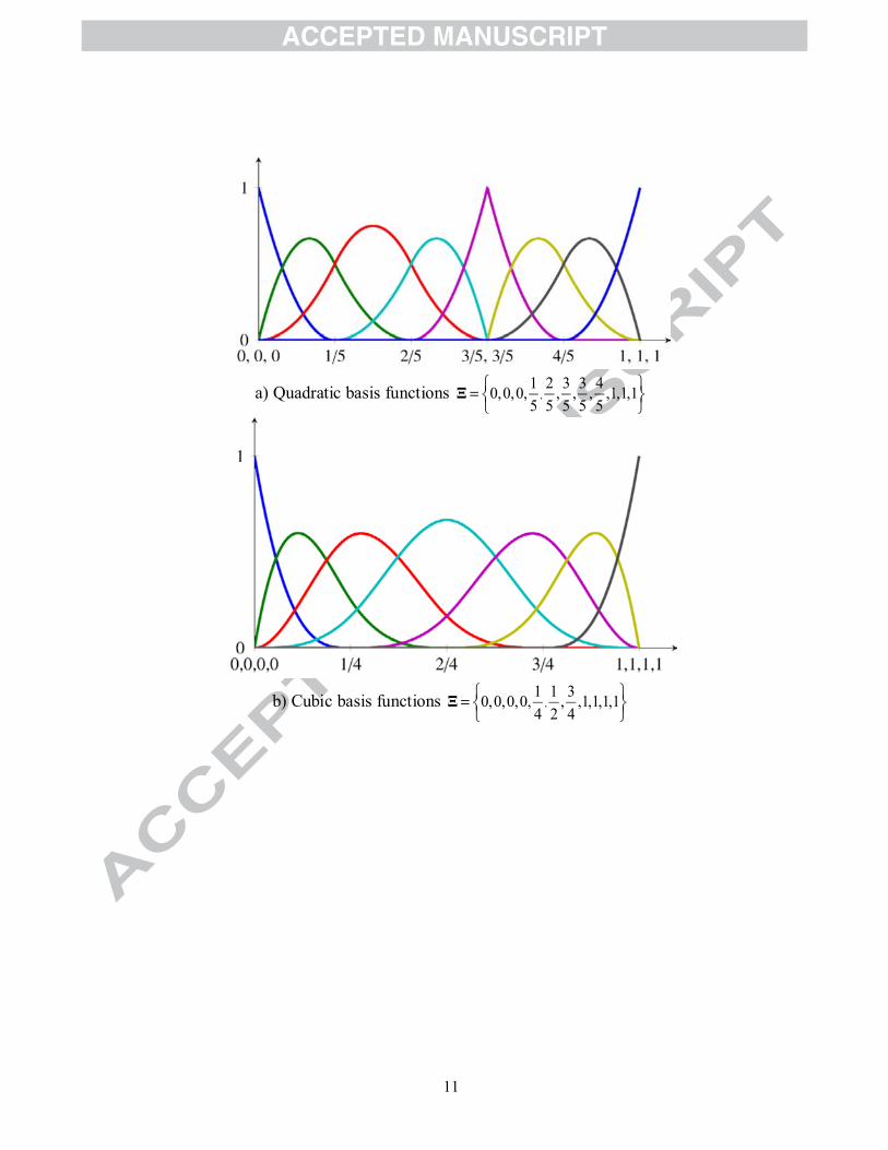
Figure 4 depicts the set of one-dimensional and two-dimensional B-spline basis functions.
1, , 1 1, 1
1 1
i pii p i p i p
i p i i p i
N N N
as p = 0, 1,0
10 otherwise
i ii
ifN
(21)
, ,,A i p j qN N M (22)
11
a) Quadratic basis functions ,1 2 3 3 40,0,0, , , , ,1,1,15 5 5 5 5
b) Cubic basis functions ,1 1 30,0,0,0, , ,1,1,1,14 2 4
12
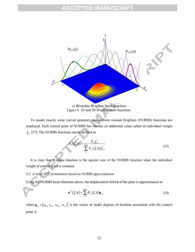
c) Bivariate B-spline basis functionFigure 4. 1D and 2D B-spline basis functions.
To model exactly some curved geometry non-uniform rational B-splines (NURBS) functions are
employed. Each control point of NURBS has thereby an additional value called an individual weight
A [37]. The NURBS functions can be defined as
,,
A AA m n
A AA
NRN (23)
It is clear that B-spline function is the special case of the NURBS function when the individual
weight of control point is constant.
3.2. A novel RPT formulation based on NURBS approximation
Using the NURBS basis functions above, the displacement field u of the plate is approximated as
, ,m n
hA A
ARu q (24)
where 0 0T
A A A b A sAu v w wq is the vector of nodal degrees of freedom associated with the control
point A.
13
Substituting Eq. (24) into Eq. (9), the in-plane and shear strains can be rewritten as:
1 20
1
m n TT T T TTT T T T m b b sb s s A A A A A
A(25)
in which
, ,1
, ,
, , ,
0 0 0 0 0 00 0 0 , 0 0 0
0 0 0 0 2 0
A x A xxm bA A y A A yy
A y A x A xy
R RR R
R R RB B ,
,,2
,,
,
0 0 00 0 0
0 0 0 ,0 0 0
0 0 0 2
A xxA xb s
A A yy AA y
A xy
RR
RR
RB B
(26)
Substituting Eq. (25) into Eqs.(14), (16) and (20), the formulations of static, free vibration and
buckling problem are rewritten in the following form
Kq = F (27)
2K M q 0 (28)
cr gK K q 0 (29)
where the global stiffness matrix K is given by
1 1
2 2
d
Tm m
b b sT s s
b b
B BA B EK B B D F B B D B
E F HB B(30)
and the load vector is computed by
0 dqF R (31)
where
0 0 A AR RR (32)
14
the global mass matrix M is expressed as
dTM R mR (33)
where
1
2 1 ,
,3
0 0 0, 0 0 0 ;
0 0 0
A
A x
A x
RR
R
RR R R
R
2 , 3
,
0 0 0 0 00 0 0 ; 0 0 0 00 0 0 0 0 0 0
A A A
A y
A y
R R RR
RR R
(34)
the geometric stiffness matrix is
0 dTg g
gK B N B (35)
where
, ,
, ,
0 00 0
A x A xgA
A y A y
R RR R
B (36)
in which , cr are the natural frequency and the critical buckling value, respectively.
It is observed from Eq. (30) that the SCF is no longer involved in the stiffness formulation. Herein, 1b
AB and 2bAB contain second-order derivatives of the shape function. Hence, it requires C1-continuous
element in approximate formulations. It is now interesting to note that our present formulation based on
IGA naturally satisfies C1-continuity from the theoretical/mechanical viewpoint of FGM plates [30, 52].
In our work, the basis functions are Cp-1 continuous. Therefore, as 2p , the present method always
satisfies C1-requirement in approximate formulations based on the RPT.
4. Results and discussions
In this section, the plates with two kinds of shape such as square and circle are modeled. The FGM
plates are made from Aluminum/Alumina (Al/Al2O3) or Aluminum/Zirconia (Al/ZrO2) and the
15
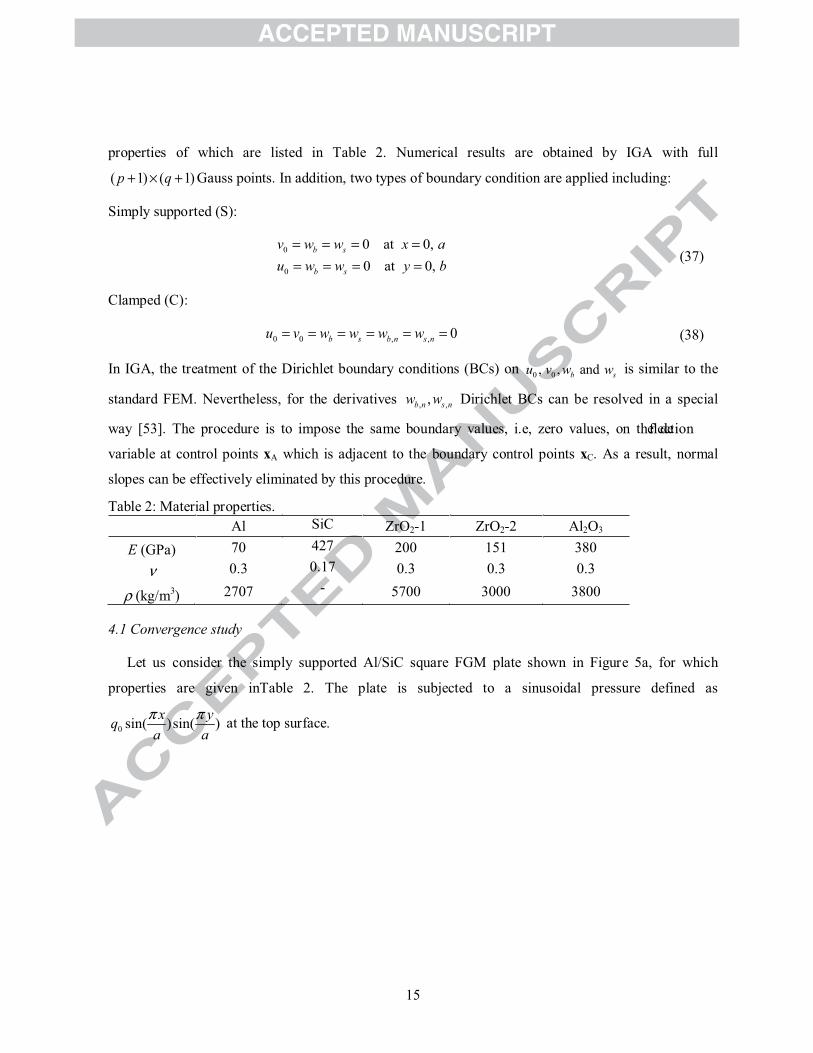
properties of which are listed in Table 2. Numerical results are obtained by IGA with full
( 1) ( 1)p q Gauss points. In addition, two types of boundary condition are applied including:
Simply supported (S):
0
0
0 at 0,0 at 0,
b s
b s
v w w x au w w y b
(37)
Clamped (C):
0 0 , , 0b s b n s nu v w w w w (38)
In IGA, the treatment of the Dirichlet boundary conditions (BCs) on 0 0, , andb su v w w is similar to the
standard FEM. Nevertheless, for the derivatives , ,,b n s nw w Dirichlet BCs can be resolved in a special
way [53]. The procedure is to impose the same boundary values, i.e, zero values, on the de
variable at control points xA which is adjacent to the boundary control points xC. As a result, normal
slopes can be effectively eliminated by this procedure.
Table 2: Material properties.Al SiC ZrO2-1 ZrO2-2 Al2O3
E (GPa) 70 427 200 151 3800.3 0.17 0.3 0.3 0.3
(kg/m3) 2707 - 5700 3000 3800
4.1 Convergence study
Let us consider the simply supported Al/SiC square FGM plate shown in Figure 5a, for which
properties are given inTable 2. The plate is subjected to a sinusoidal pressure defined as
0 sin( )sin( )x yqa a
at the top surface.
16
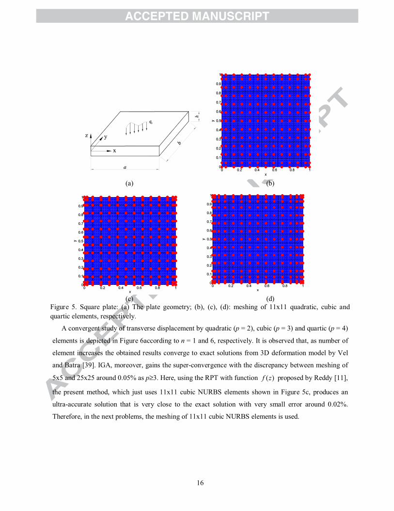
(a) (b)
(c) (d)Figure 5. Square plate: (a) The plate geometry; (b), (c), (d): meshing of 11x11 quadratic, cubic and quartic elements, respectively.
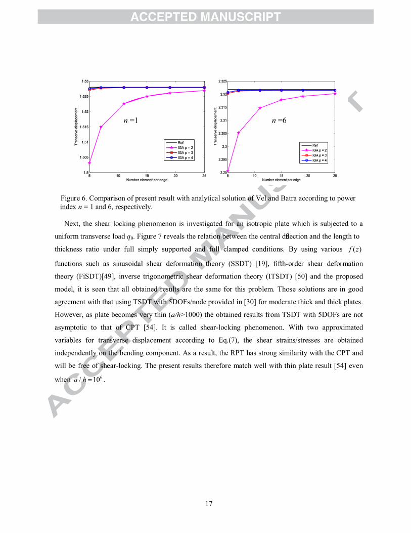
A convergent study of transverse displacement by quadratic (p = 2), cubic (p = 3) and quartic (p = 4)
elements is depicted in Figure 6according to n = 1 and 6, respectively. It is observed that, as number of
element increases the obtained results converge to exact solutions from 3D deformation model by Vel
and Batra [39]. IGA, moreover, gains the super-convergence with the discrepancy between meshing of
5x5 and 25x25 around 0.05% as p 3. Here, using the RPT with function ( )f z proposed by Reddy [11],
the present method, which just uses 11x11 cubic NURBS elements shown in Figure 5c, produces an
ultra-accurate solution that is very close to the exact solution with very small error around 0.02%.
Therefore, in the next problems, the meshing of 11x11 cubic NURBS elements is used.
17
Figure 6. Comparison of present result with analytical solution of Vel and Batra according to power index n = 1 and 6, respectively.
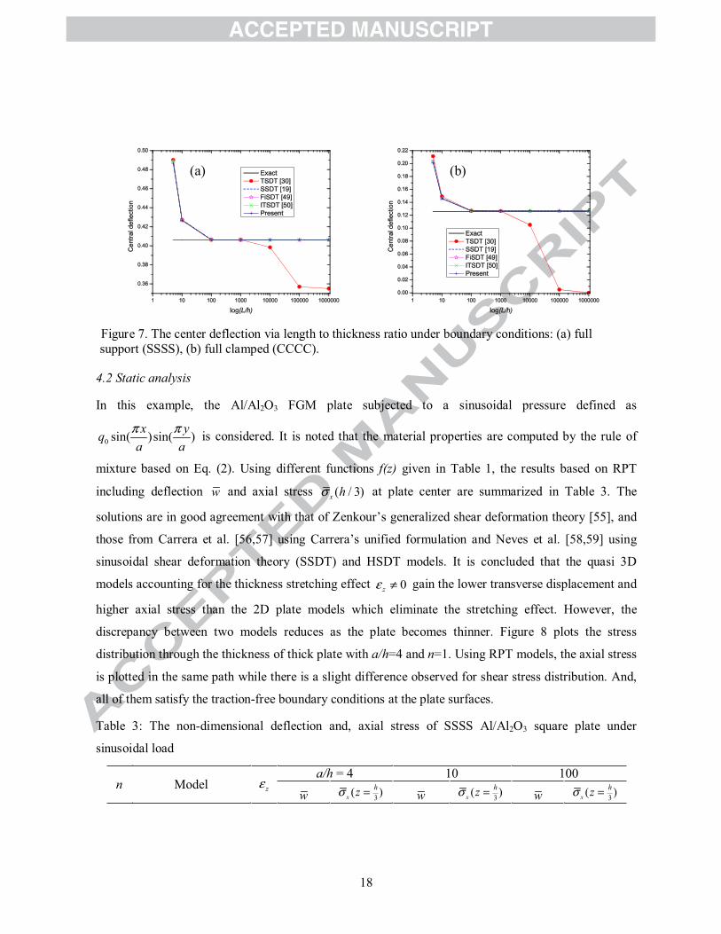
Next, the shear locking phenomenon is investigated for an isotropic plate which is subjected to a
uniform transverse load q0. Figure 7 reveals the relation between the central de
thickness ratio under full simply supported and full clamped conditions. By using various ( )f z
functions such as sinusoidal shear deformation theory (SSDT) [19], fifth-order shear deformation
theory (FiSDT)[49], inverse trigonometric shear deformation theory (ITSDT) [50] and the proposed
model, it is seen that all obtained results are the same for this problem. Those solutions are in good
agreement with that using TSDT with 5DOFs/node provided in [30] for moderate thick and thick plates.
However, as plate becomes very thin (a/h>1000) the obtained results from TSDT with 5DOFs are not
asymptotic to that of CPT [54]. It is called shear-locking phenomenon. With two approximated
variables for transverse displacement according to Eq.(7), the shear strains/stresses are obtained
independently on the bending component. As a result, the RPT has strong similarity with the CPT and
will be free of shear-locking. The present results therefore match well with thin plate result [54] even
when 6/ 10a h .
n =1 n =6
18
Figure 7. The center deflection via length to thickness ratio under boundary conditions: (a) full support (SSSS), (b) full clamped (CCCC).
4.2 Static analysis
In this example, the Al/Al2O3 FGM plate subjected to a sinusoidal pressure defined as
0 sin( )sin( )x yqa a
is considered. It is noted that the material properties are computed by the rule of
mixture based on Eq. (2). Using different functions f(z) given in Table 1, the results based on RPT
including deflection w and axial stress ( / 3)x h at plate center are summarized in Table 3. The
solutions are in good agreement with that of Zenkour’s generalized shear deformation theory [55], and
those from Carrera et al. [56,57] using Carrera’s unified formulation and Neves et al. [58,59] using
sinusoidal shear deformation theory (SSDT) and HSDT models. It is concluded that the quasi 3D
models accounting for the thickness stretching effect 0z gain the lower transverse displacement and
higher axial stress than the 2D plate models which eliminate the stretching effect. However, the
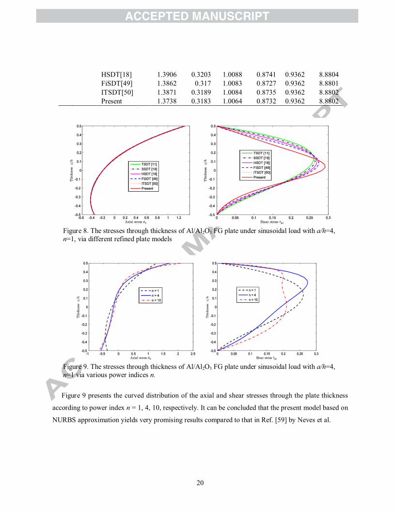
discrepancy between two models reduces as the plate becomes thinner. Figure 8 plots the stress
distribution through the thickness of thick plate with a/h=4 and n=1. Using RPT models, the axial stress
is plotted in the same path while there is a slight difference observed for shear stress distribution. And,
all of them satisfy the traction-free boundary conditions at the plate surfaces.
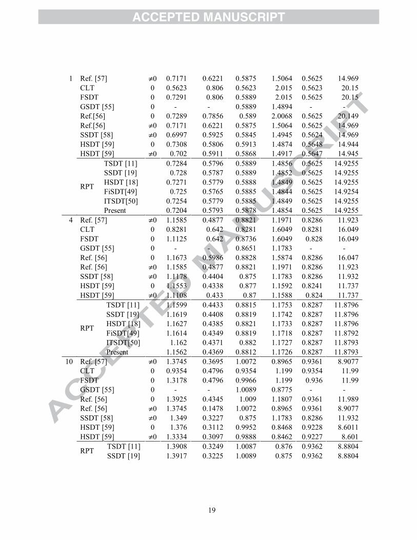
Table 3: The non-dimensional deflection and, axial stress of SSSS Al/Al2O3 square plate under
sinusoidal load
n Model z
a/h = 4 10 100
w 3( )xhz w 3( )x
hz w 3( )xhz
(a) (b)
19
1 Ref. [57] 0 0.7171 0.6221 0.5875 1.5064 0.5625 14.969CLT 0 0.5623 0.806 0.5623 2.015 0.5623 20.15FSDT 0 0.7291 0.806 0.5889 2.015 0.5625 20.15GSDT [55] 0 - - 0.5889 1.4894 - -Ref.[56] 0 0.7289 0.7856 0.589 2.0068 0.5625 20.149Ref.[56] 0 0.7171 0.6221 0.5875 1.5064 0.5625 14.969SSDT [58] 0 0.6997 0.5925 0.5845 1.4945 0.5624 14.969HSDT [59] 0 0.7308 0.5806 0.5913 1.4874 0.5648 14.944HSDT [59] 0 0.702 0.5911 0.5868 1.4917 0.5647 14.945
RPT
TSDT [11] 0.7284 0.5796 0.5889 1.4856 0.5625 14.9255SSDT [19] 0.728 0.5787 0.5889 1.4852 0.5625 14.9255HSDT [18] 0.7271 0.5779 0.5888 1.4849 0.5625 14.9255FiSDT[49] 0.725 0.5765 0.5885 1.4844 0.5625 14.9254ITSDT[50] 0.7254 0.5779 0.5885 1.4849 0.5625 14.9255Present 0.7204 0.5793 0.5878 1.4854 0.5625 14.9255
4 Ref. [57] 0 1.1585 0.4877 0.8821 1.1971 0.8286 11.923CLT 0 0.8281 0.642 0.8281 1.6049 0.8281 16.049FSDT 0 1.1125 0.642 0.8736 1.6049 0.828 16.049GSDT [55] 0 - - 0.8651 1.1783 - -Ref. [56] 0 1.1673 0.5986 0.8828 1.5874 0.8286 16.047Ref. [56] 0 1.1585 0.4877 0.8821 1.1971 0.8286 11.923SSDT [58] 0 1.1178 0.4404 0.875 1.1783 0.8286 11.932HSDT [59] 0 1.1553 0.4338 0.877 1.1592 0.8241 11.737HSDT [59] 0 1.1108 0.433 0.87 1.1588 0.824 11.737
RPT
TSDT [11] 1.1599 0.4433 0.8815 1.1753 0.8287 11.8796SSDT [19] 1.1619 0.4408 0.8819 1.1742 0.8287 11.8796HSDT [18] 1.1627 0.4385 0.8821 1.1733 0.8287 11.8796FiSDT[49] 1.1614 0.4349 0.8819 1.1718 0.8287 11.8792ITSDT[50] 1.162 0.4371 0.882 1.1727 0.8287 11.8793Present 1.1562 0.4369 0.8812 1.1726 0.8287 11.8793
10 Ref. [57] 0 1.3745 0.3695 1.0072 0.8965 0.9361 8.9077CLT 0 0.9354 0.4796 0.9354 1.199 0.9354 11.99FSDT 0 1.3178 0.4796 0.9966 1.199 0.936 11.99GSDT [55] 0 - - 1.0089 0.8775 - -Ref. [56] 0 1.3925 0.4345 1.009 1.1807 0.9361 11.989Ref. [56] 0 1.3745 0.1478 1.0072 0.8965 0.9361 8.9077SSDT [58] 0 1.349 0.3227 0.875 1.1783 0.8286 11.932HSDT [59] 0 1.376 0.3112 0.9952 0.8468 0.9228 8.6011HSDT [59] 0 1.3334 0.3097 0.9888 0.8462 0.9227 8.601
RPT TSDT [11] 1.3908 0.3249 1.0087 0.876 0.9362 8.8804SSDT [19] 1.3917 0.3225 1.0089 0.875 0.9362 8.8804
20
HSDT[18] 1.3906 0.3203 1.0088 0.8741 0.9362 8.8804FiSDT[49] 1.3862 0.317 1.0083 0.8727 0.9362 8.8801ITSDT[50] 1.3871 0.3189 1.0084 0.8735 0.9362 8.8802Present 1.3738 0.3183 1.0064 0.8732 0.9362 8.8802
Figure 8. The stresses through thickness of Al/Al2O3 FG plate under sinusoidal load with a/h=4, n=1, via different refined plate models
Figure 9. The stresses through thickness of Al/Al2O3 FG plate under sinusoidal load with a/h=4, n=1 via various power indices n.
Figure 9 presents the curved distribution of the axial and shear stresses through the plate thickness
according to power index n = 1, 4, 10, respectively. It can be concluded that the present model based on
NURBS approximation yields very promising results compared to that in Ref. [59] by Neves et al.
21
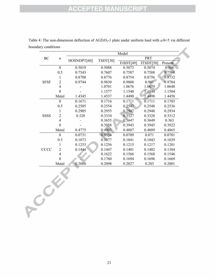
Table 4: The non-dimension deflection of Al/ZrO2-1 plate under uniform load with a/h=5 via different
boundary conditions
BC nModel
HOSNDPT[60] TSDT[30] PRTFiSDT[49] ITSDT[50] Present
0 0.5019 0.5088 0.5073 0.5074 0.5060.5 0.7543 0.7607 0.7587 0.7588 0.75681 0.8708 0.8776 0.8754 0.8756 0.8732
SFSF 2 0.9744 0.9830 0.9808 0.981 0.97844 - 1.0701 1.0676 1.0679 1.06488 - 1.1577 1.1540 1.1544 1.1504
Metal 1.4345 1.4537 1.4490 1.4498 1.44580 0.1671 0.1716 0.1711 0.1711 0.1703
0.5 0.2505 0.2554 0.2547 0.2548 0.25361 0.2905 0.2955 0.2947 0.2948 0.2934
SSSS 2 0.328 0.3334 0.3327 0.3328 0.33124 - 0.3655 0.3647 0.3649 0.3638 - 0.3958 0.3943 0.3945 0.3922
Metal 0.4775 0.4903 0.4887 0.4889 0.48650 0.0731 0.0734 0.0709 0.071 0.0701
0.5 0.1073 0.1077 0.1041 0.1043 0.10291 0.1253 0.1256 0.1215 0.1217 0.1201
CCCC 2 0.1444 0.1447 0.1401 0.1402 0.13844 - 0.1622 0.1566 0.1568 0.15468 - 0.1760 0.1694 0.1696 0.1669
Metal 0.2088 0.2098 0.2027 0.203 0.2001
22
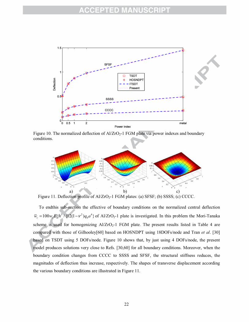
Figure 10. The normalized deflection of Al/ZrO2-1 FGM plate via power indexes and boundary conditions.
a) b) c)Figure 11. Deflection profile of Al/ZrO2-1 FGM plates: (a) SFSF; (b) SSSS; (c) CCCC.
To endthis sub-section the effective of boundary conditions on the normalized central deflection 3 2 4
0100 / {12(1 ) }c c mw w E h q a of Al/ZrO2-1 plate is investigated. In this problem the Mori-Tanaka
scheme is used for homogenizing Al/ZrO2-1 FGM plate. The present results listed in Table 4 are
compared with those of Gilhooley[60] based on HOSNDPT using 18DOFs/node and Tran et al. [30]
based on TSDT using 5 DOFs/node. Figure 10 shows that, by just using 4 DOFs/node, the present
model produces solutions very close to Refs. [30,60] for all boundary conditions. Moreover, when the
boundary condition changes from CCCC to SSSS and SFSF, the structural stiffness reduces, the
magnitudes of deflection thus increase, respectively. The shapes of transverse displacement according
the various boundary conditions are illustrated in Figure 11.
23
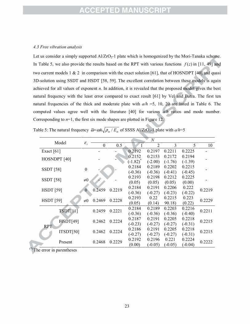
4.3 Free vibration analysis
Let us consider a simply supported Al/ZrO2-1 plate which is homogenized by the Mori-Tanaka scheme.
In Table 5, we also provide the results based on the RPT with various functions ( )f z in [11, 49] and
two current models 1 & 2 in comparison with the exact solution [61], that of HOSNDPT [40] and quasi
3D-solution using SSDT and HSDT [58, 59]. The excellent correlation between these models is again
achieved for all values of exponent n. In addition, it is revealed that the proposed model gives the best
natural frequency with the least error compared to exact result [61] by Vel and Batra. The first ten
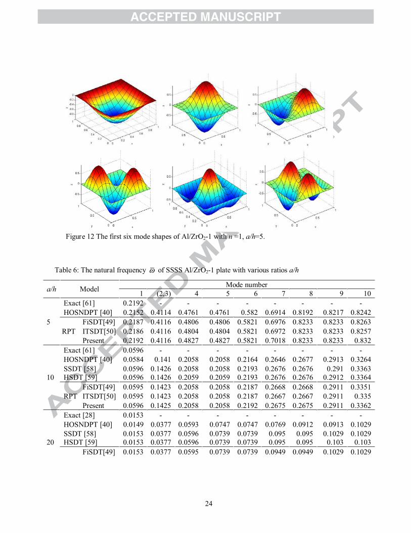
natural frequencies of the thick and moderate plate with a/h =5, 10, 20 are listed in Table 6. The
computed values agree well with the literature [40] for various a/h ratios and mode number.
Corresponding to n=1, the first six mode shapes are plotted in Figure 12.
Table 5: The natural frequency = /m mh E of SSSS Al/ZrO2-1 plate with a/h=5
Model zN
0 0.5 1 2 3 5 10Exact [61] - - 0.2192 0.2197 0.2211 0.2225 -
HOSNDPT [40] - - 0.2152 (-1.82)*
0.2153(-2.00)
0.2172(-1.76)
0.2194(-1.39) -
SSDT [58] 0 - - 0.2184(-0.36)
0.2189(-0.36)
0.2202(-0.41)
0.2215(-0.45) -
SSDT [58] 0 - - 0.2193(0.05)
0.2198(0.05)
0.2212(0.05)
0.2225(0.00) -
HSDT [59] 0 0.2459 0.2219 0.2184(-0.36)
0.2191(-0.27)
0.2206(-0.23)
0.222(-0.22) 0.2219
HSDT [59] 0 0.2469 0.2228 0.2193(0.05)
0.22(0.14)
0.221590.18)
0.223(0.22) 0.2229
RPT
TSDT[11] 0.2459 0.2221 0.2184(-0.36)
0.2189(-0.36)
0.2203(-0.36)
0.2216(-0.40) 0.2211
FiSDT[49] 0.2462 0.2224 0.2187(-0.23)
0.2191(-0.27)
0.2205(-0.27)
0.2218(-0.31) 0.2215
ITSDT[50] 0.2462 0.2224 0.2186(-0.27)
0.2191(-0.27)
0.2205(-0.27)
0.2218(-0.31) 0.2215
Present 0.2468 0.2229 0.2192(0.00)
0.2196(-0.05)
0.221(-0.05)
0.2224(-0.04) 0.2222
(*) The error in parentheses
24
Figure 12 The first six mode shapes of Al/ZrO2-1 with n =1, a/h=5.
Table 6: The natural frequency of SSSS Al/ZrO2-1 plate with various ratios a/h
a/h Model Mode number1 (2,3) 4 5 6 7 8 9 10
Exact [61] 0.2192 - - - - - - - -HOSNDPT [40] 0.2152 0.4114 0.4761 0.4761 0.582 0.6914 0.8192 0.8217 0.8242
5 FiSDT[49] 0.2187 0.4116 0.4806 0.4806 0.5821 0.6976 0.8233 0.8233 0.8263RPT ITSDT[50] 0.2186 0.4116 0.4804 0.4804 0.5821 0.6972 0.8233 0.8233 0.8257
Present 0.2192 0.4116 0.4827 0.4827 0.5821 0.7018 0.8233 0.8233 0.832Exact [61] 0.0596 - - - - - - - -HOSNDPT [40] 0.0584 0.141 0.2058 0.2058 0.2164 0.2646 0.2677 0.2913 0.3264SSDT [58] 0.0596 0.1426 0.2058 0.2058 0.2193 0.2676 0.2676 0.291 0.3363
10 HSDT [59] 0.0596 0.1426 0.2059 0.2059 0.2193 0.2676 0.2676 0.2912 0.3364FiSDT[49] 0.0595 0.1423 0.2058 0.2058 0.2187 0.2668 0.2668 0.2911 0.3351
RPT ITSDT[50] 0.0595 0.1423 0.2058 0.2058 0.2187 0.2667 0.2667 0.2911 0.335Present 0.0596 0.1425 0.2058 0.2058 0.2192 0.2675 0.2675 0.2911 0.3362
Exact [28] 0.0153 - - - - - - - -HOSNDPT [40] 0.0149 0.0377 0.0593 0.0747 0.0747 0.0769 0.0912 0.0913 0.1029SSDT [58] 0.0153 0.0377 0.0596 0.0739 0.0739 0.095 0.095 0.1029 0.1029
20 HSDT [59] 0.0153 0.0377 0.0596 0.0739 0.0739 0.095 0.095 0.103 0.103FiSDT[49] 0.0153 0.0377 0.0595 0.0739 0.0739 0.0949 0.0949 0.1029 0.1029
25
RPT ITSDT[50] 0.0153 0.0377 0.0595 0.0739 0.0739 0.0949 0.0949 0.1029 0.1029Present 0.0153 0.0377 0.0596 0.0739 0.0739 0.095 0.095 0.1029 0.1029
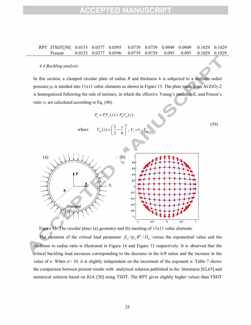
4.4 Buckling analysis
In this section, a clamped circular plate of radius R and thickness h is subjected to a uniform radial
pressure p0 is meshed into 11x11 cubic elements as shown in Figure 13. The plate made from Al/ZrO2-2
is homogenized following the rule of mixture, in which the effective Young’s modulus Ee and Poison’s
ratio e are calculated according to Eq. (40).
Figure 13. The circular plate: (a) geometry and (b) meshing of 11x11 cubic elements.
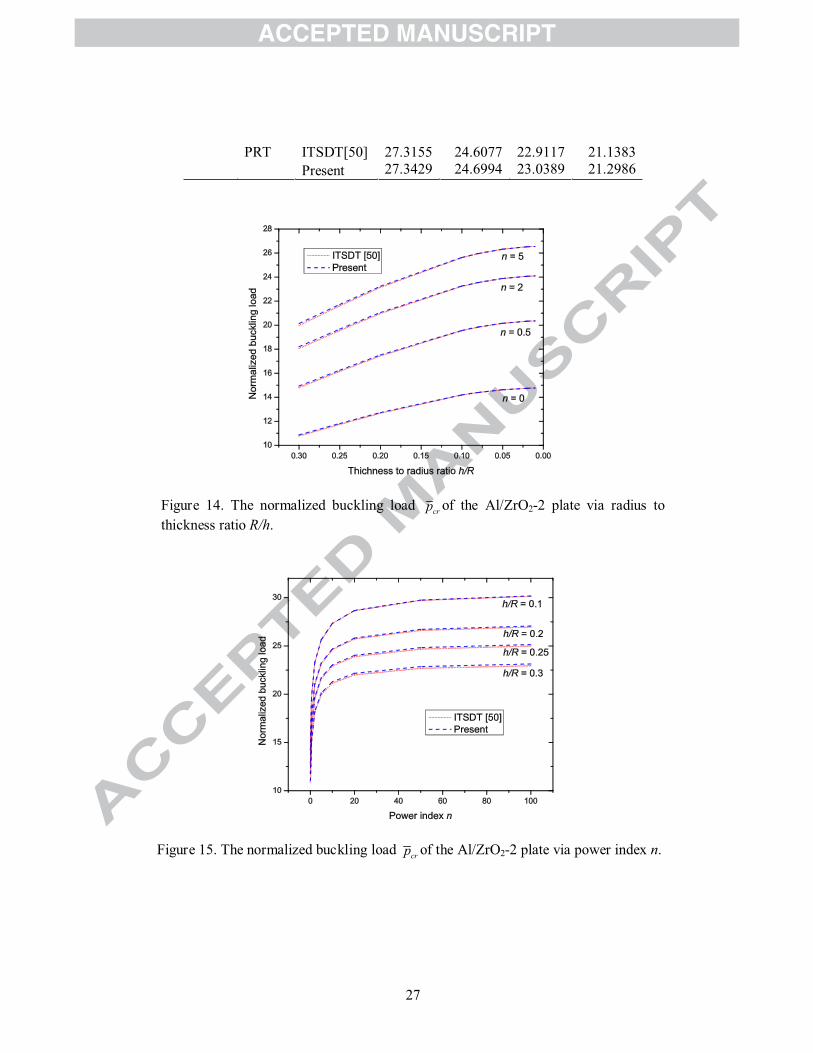
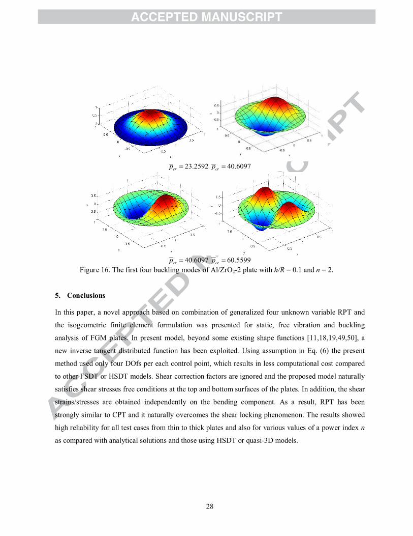
The variation of the critical load parameter 2= /cr cr mp p R D versus the exponential value and the
thickness to radius ratio is illustrated in Figure 14 and Figure 15 respectively. It is observed that the
critical buckling load increases corresponding to the decrease in the h/R ratios and the increase in the
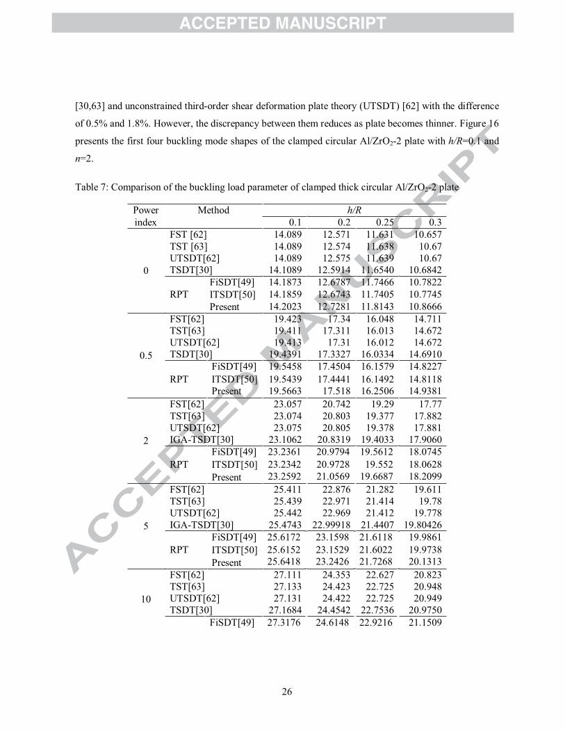
value of n. When n> 10, it is slightly independent on the increment of the exponent n. Table 7 shows
the comparison between present results with analytical solution published in the literatures [62,63] and
numerical solution based on IGA [30] using TSDT. The RPT gives slightly higher values than TSDT
( ) ( )e c c m mP PV z P V z
where 1( )2
n
mzV zh
, 1c mV V(39)
(b)(a)
26
[30,63] and unconstrained third-order shear deformation plate theory (UTSDT) [62] with the difference
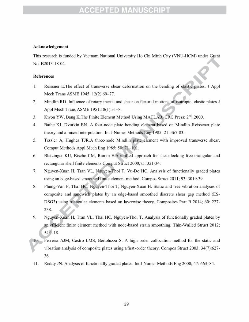
of 0.5% and 1.8%. However, the discrepancy between them reduces as plate becomes thinner. Figure 16
presents the first four buckling mode shapes of the clamped circular Al/ZrO2-2 plate with h/R=0.1 and
n=2.
Table 7: Comparison of the buckling load parameter of clamped thick circular Al/ZrO2-2 plate
Power Method h/Rindex 0.1 0.2 0.25 0.3
0
FST [62] 14.089 12.571 11.631 10.657TST [63] 14.089 12.574 11.638 10.67UTSDT[62] 14.089 12.575 11.639 10.67TSDT[30] 14.1089 12.5914 11.6540 10.6842
RPTFiSDT[49] 14.1873 12.6787 11.7466 10.7822ITSDT[50] 14.1859 12.6743 11.7405 10.7745Present 14.2023 12.7281 11.8143 10.8666
0.5
FST[62] 19.423 17.34 16.048 14.711TST[63] 19.411 17.311 16.013 14.672UTSDT[62] 19.413 17.31 16.012 14.672TSDT[30] 19.4391 17.3327 16.0334 14.6910
FiSDT[49] 19.5458 17.4504 16.1579 14.8227RPT ITSDT[50] 19.5439 17.4441 16.1492 14.8118
Present 19.5663 17.518 16.2506 14.9381
2
FST[62] 23.057 20.742 19.29 17.77TST[63] 23.074 20.803 19.377 17.882UTSDT[62] 23.075 20.805 19.378 17.881IGA-TSDT[30] 23.1062 20.8319 19.4033 17.9060
FiSDT[49] 23.2361 20.9794 19.5612 18.0745RPT ITSDT[50] 23.2342 20.9728 19.552 18.0628
Present 23.2592 21.0569 19.6687 18.2099
5
FST[62] 25.411 22.876 21.282 19.611TST[63] 25.439 22.971 21.414 19.78UTSDT[62] 25.442 22.969 21.412 19.778IGA-TSDT[30] 25.4743 22.99918 21.4407 19.80426
FiSDT[49] 25.6172 23.1598 21.6118 19.9861RPT ITSDT[50] 25.6152 23.1529 21.6022 19.9738
Present 25.6418 23.2426 21.7268 20.1313
10
FST[62] 27.111 24.353 22.627 20.823TST[63] 27.133 24.423 22.725 20.948UTSDT[62] 27.131 24.422 22.725 20.949TSDT[30] 27.1684 24.4542 22.7536 20.9750
FiSDT[49] 27.3176 24.6148 22.9216 21.1509
27
PRT ITSDT[50] 27.3155 24.6077 22.9117 21.1383Present 27.3429 24.6994 23.0389 21.2986
Figure 14. The normalized buckling load crp of the Al/ZrO2-2 plate via radius to thickness ratio R/h.
Figure 15. The normalized buckling load crp of the Al/ZrO2-2 plate via power index n.
28
23.2592crp 40.6097crp
40.6097crp 60.5599crpFigure 16. The first four buckling modes of Al/ZrO2-2 plate with h/R = 0.1 and n = 2.
5. Conclusions
In this paper, a novel approach based on combination of generalized four unknown variable RPT and
the isogeometric finite element formulation was presented for static, free vibration and buckling
analysis of FGM plates. In present model, beyond some existing shape functions [11,18,19,49,50], a
new inverse tangent distributed function has been exploited. Using assumption in Eq. (6) the present
method used only four DOfs per each control point, which results in less computational cost compared
to other FSDT or HSDT models. Shear correction factors are ignored and the proposed model naturally
satisfies shear stresses free conditions at the top and bottom surfaces of the plates. In addition, the shear
strains/stresses are obtained independently on the bending component. As a result, RPT has been
strongly similar to CPT and it naturally overcomes the shear locking phenomenon. The results showed
high reliability for all test cases from thin to thick plates and also for various values of a power index n
as compared with analytical solutions and those using HSDT or quasi-3D models.
29
Acknowledgement
This research is funded by Vietnam National University Ho Chi Minh City (VNU-HCM) under Grant
No. B2013-18-04.
References
1. Reissner E.The effect of transverse shear deformation on the bending of elastic plates. J Appl
Mech Trans ASME 1945; 12(2):69–77.
2. Mindlin RD. In
Appl Mech Trans ASME 1951;18(1):31–8.
3. Kwon YW, Bang K.The Finite Element Method Using MATLAB, CRC Press; 2nd, 2000.
4. Bathe KJ, Dvorkin EN. A four-node plate bending element based on Mindlin–Reissener plate
theory and a mixed interpolation. Int J Numer Methods Eng 1985; 21: 367-83.
5. Tessler A, Hughes TJR.A three-node Mindlin plate element with improved transverse shear.
Comput Methods Appl Mech Eng 1985; 50: 71–101.
6. Bletzinger KU, Bischoff M, Ramm E.A unified approach for shear-locking free triangular and
rectangular shell finite elements.Comput Struct 2000;75: 321-34.
7. Nguyen-Xuan H, Tran VL, Nguyen-Thoi T, Vu-Do HC. Analysis of functionally graded plates
using an edge-based smoothed finite element method. Compos Struct 2011; 93: 3019-39.
8. Phung-Van P, Thai HC, Nguyen-Thoi T, Nguyen-Xuan H. Static and free vibration analyses of
composite and sandwich plates by an edge-based smoothed discrete shear gap method (ES-
DSG3) using triangular elements based on layerwise theory. Composites Part B 2014; 60: 227-
238.
9. Nguyen-Xuan H, Tran VL, Thai HC, Nguyen-Thoi T. Analysis of functionally graded plates by
an efficient finite element method with node-based strain smoothing. Thin-Walled Struct 2012;
54:1-18.
10. Ferreira AJM, Castro LMS, Bertoluzza S. A high order collocation method for the static and
vibration analysis of composite plates using a -order theory. Compos Struct 2003; 34(7):627-
36.
11. Reddy JN. Analysis of functionally graded plates. Int J Numer Methods Eng 2000; 47: 663–84.
30
12. Reddy JN. A simple higher-order theory for laminated composite plates. J Appl Mech 1984; 51:
745–52.
13. Mantari JL, Oktem AS, Guedes Soares C. Bending response of functionally graded plates by
using a new higher order shear deformation theory. Compos Struct 2012; 94: 714–23.
14. Zenkour AM. The re
2009; 51(11–12):869–80.
15. Atmane HA, Tounsi A, Mechab I, Bedia EI. Free vibration analysis of functionally graded plates
resting on Winkler-Pasternak elastic foundations using a new shear deformation theory. Int J
Mech Mater Des 2010; 6(2):113–21.
16. Soldatos KP. A transverse shear deformation theory for homogenous monoclinic plates. Acta
Mechanica 1992; 94:195–220.
17. Touratier M.An ef –16.
18. Karama M, Afaq KS, Mistou S. Mechanical behavior of laminated composite beam by new
multi-layered laminated composite structures model with transverse shear stress continuity. Int J
Solids and Structures 2003; 40: 1525-1546.
19. Arya H, Shimpi RP, Naik NK.A zigzag model for laminated composite beams. Compos Struct
2002; 56(1): 21-4.
20. Aydogdu M. A new shear deformation theory for laminated composite plates. Compos Struct
2009; 89(1):94-101.
21. Senthilnathan NR, Lim SP, Lee KH, Chow ST. Buckling of shear-deformable plates. AIAA
Journal 1987; 25(9):1268-71.
22. Thai HT, Choi DH.A refined plate theory for functionally graded plates resting on elastic
foundation. Composites Science and Technology 2011; 71(16):1850-8.
23. Kim SE, Thai HT, Lee J. A two variable refined plate theory for laminated composite plates.
Compos Struct 2009; 89(2):197-205.
24. Benachour A, Tahar HD, Atmane HA, Tounsi A, Ahmed MS. A four variable refined plate theory
for free vibrations of functionally graded plates with arbitrary gradient. Composites Part B:
Engineering 2011; 42: 1386-94.
25. Mechab I, Mechab B, Benaissa S. Static and dynamic analysis of functionally graded plates using
Four-variable refined plate theory by the new function. Composites Part B 2013; 45:748-57.
31
26. Shimpi RP. Refined plate theory and its variants. AIAA Journal 2002; 40(1):137-46.
27. Shimpi RP, Patel HG. A two variable refined plate theory for orthotropic plate analysis. Int J
Solids and Structures 2006; 43(22–23); 6783-6799.
28. Shimpi RP, Patel HG. Free vibrations of plate using two variable refined plate theory. J Sound
Vib 2006; 296(4–5):979-99.
29. Thai HC, Nguyen-Xuan H, Bordas SPA, Nguyen-Thanh N, Rabczuk T. Isogeometric analysis of
laminated composite plates using the higher-order shear deformation theory.Mechanics of
Advanced Materials and Structures 2013 (in press).
30. Tran VL, Ferreira AJM, Nguyen-Xuan H. Isogeometric analysis of functionally graded plates
using higher-order shear deformation theory. Composites Part B 2013; 51: 368-83.
31. Thai HC, Tran VL, Tran TD, Nguyen-Thoi T, Nguyen-Xuan H. Analysis of laminated composite
plates using higher-order shear deformation plate theory and node-based smoothed discrete shear
gap method, Applied Mathematical Modelling 2012; 36: 5657-77.
32. Tran VL, Nguyen-Thoi T, Thai HC, Nguyen-Xuan H. An edge-based smoothed discrete shear
gap method (ES-DSG) using the C0-type higher-order shear deformation theory for analysis of
laminated composite plates, Mechanics of Advanced Materials and Structures 2012;
DOI:10.1080/15376494.2012.736055.
33. Phung-Van P, Nguyen-Thoi T, Tran VL, Nguyen-Xuan H. A cell-based smoothed discrete shear
gap method (CS-DSG3) based on the C0-type higher-order shear deformation theory for static and
free vibration analyses of functionally graded plates. Computational Materials Science 2013; 79:
857–72.
34. Sankara CA and Igengar NGR. A C0 element for free vibration analysis of laminated composite
plates J. Sound and Vib 1996; 191: 721–38.
35. Kant T, Swaminathan K. Analytical solutions for the static analysis of laminated composite and
sandwich plates based on a higher order refined theory Composite Structures 2002;56(4):329-44.
36. Reddy JN. Mechanics of laminated composite plates-theory and analysis. NewYork: CRC Press,
1997.
37. Hughes TJR, Cottrell JA, Bazilevs Y. Isogeometric analysis: CAD, finite elements, NURBS,
exact geometry and mesh refinement. Comput Methods Appl Mech Eng 2005; 194: 4135–95.
32
38. Cottrell JA, Hughes TJR, Bazilevs Y. Isogeometric Analysis, Towards Integration of CAD and
FEA, Wiley, 2009.
39. Vel SS, Batra RC. Exact solution for thermoelastic deformations of functionally graded thick
rectangular plates. AIAA Journal 2004; 40: 1021-33.
40. Qian LF, Batra RC, Chen LM. Static and dynamic deformations of thick functionally graded
elastic plate by using higher-order shear and normal deformable plate theory and meshless local
Petrov–Galerkin method. Composites Part B 2004; 35: 685–97.
41. Mori T, Tanaka K. Average stress in matrix and average elastic energy of materials with
mis : 571–4.
42. Mashat DS, Carrera E, Zenkour AM, Khateeb SAA, Filippi M. Free vibration of FGM layered
beams by various theories and finite elements. Composites Part B 2014; 59: 269-78.
43. Pradhan KK, Chakraverty S. Free vibration of Euler and Timoshenko functionally graded beams
by Rayleigh–Ritz method. Composites Part B 2014; 51: 175-84.
44. Yaghoobi H, Fereidoon A Mechanical and thermal buckling analysis of functionally graded
plates resting on elastic foundations: An assessment of a simple refined nth-order shear
deformation theory, Composites Part B 2013; 62: 54-64.
45. Mantari JL, Bonilla EM, Soares CG. A new tangential-exponential higher order shear
deformation theory for advanced composite plates. Composites Part B 2014; 60: 319-28.
46. Jung WY, Han SC, Park WT. A modified couple stress theory for buckling analysis of S-FGM
nanoplates embedded in Pasternak elastic medium. Composites Part B 2014; 60:746-56.
47. Shen HS, Wang H. Nonlinear vibration of shear deformable FGM cylindrical panels resting on
elastic foundations in thermal environments. Composites Part B 2014; 60:167-77.
48. Torabi J, Kiani Y, Eslami MR. Linear thermal buckling analysis of truncated hybrid FGM conical
shells, Composites Part B 2013; 50: 265-72.
49. Nguyen-Xuan H, Thai HC, Nguyen-Thoi T. Isogeometric
sandwich plates using a new higher order shear deformation theory, Composite Part B 2013;55:
558-74.
50. Thai HC, Ferreira AJM, Bordas SPA, Rabczuk T, Nguyen-Xuan H. Isogeometric analysis of
laminated composite and sandwich plates using a new inverse trigonometric shear deformation
theory. European Journal of Mechanics - A/Solids 2014; 43: 89-108.
33
51. Lee YY, Zhao Z, Liew KM. Thermoelastic analysis of functionally graded plates using the
element-free kp-Ritz method. Smart Mater Struct2009; doi:10.1088/0964-1726/18/3/035007.
52. Thai HC, Nguyen-Xuan H, Nguyen-Thanh N, Le TH, Nguyen-Thoi T. Rabczuk T, Static, free
vibration, and buckling analysis of laminated composite Reissner–Mindlin plates using NURBS-
based isogeometric approach, Int J Numer Meth Engng 2012);91(6):571–603.
53. Auricchio F, BeiraodaVeiga F, Buffa A, Lovadina C, Reali A, and Sangalli G. A fully locking-
free isogeometric approach for plane linear elasticity problems: a stream function formulation.
Comput Methods ApplMechEng 2007; 197: 160–72.
54. Timoshenko SP, Woinowsky-Krieger S. Theory of plate and shell.3rd edition McGraw-Hill,
Publishing Company, 1970.
55. Zenkour AM. Generalized shear deformation theory for bending analysis of functionally graded
plates. Applied Mathematical Modelling 2006;30(1):67-84.
56. Carrera E, Brischetto S, Cinefra M, Soave M. Effects of thickness stretching in functionally graded
plates and shells. Composites Part B: Engineering 2011;42(2):123-33.
57. Carrera E, Brischetto S, Robaldo A. Variable kinematic model for the analysis of functionally
graded material plates. AIAA Journal 2008;46(1):194-203.
58. Neves AMA, Ferreira AJM, Carrera E, Roque CMC, Cinefra M, Jorge RMN, Soares CMM.A
quasi-3D sinusoidal shear deformation theory for the static and free vibration analysis of
functionally graded plates. Composites Part B 2012;43(2):711–25.
59. Neves AMA, Ferreira AJM, Carrera E, Cinefra M, Roque CMC, Jorge RMN, Soares CMM. Static,
free vibration and buckling analysis of isotropic and sandwich functionally graded plates using a
quasi-3D higher-order shear deformation theory and a meshless technique. Composites Part B
2013; 44(1):657-74.
60. Gilhooley DF, Batra RC, Xiao JR, McCarthy MA, Gillespie JW. Analysis of thick functionally
graded plates by using higher-order shear and normal deformable plate theory and MLPG method
with radial basis functions. Comput Struct 2007; 80: 539–52.
61. Vel SS, Batra RC. Three-dimensional Exact Solution for the Vibration of Functionally Graded
Rectangular Plates. J Sound Vib 2004; 272: 703-30.

34
62. Saidi AR,Rasouli A, Sahraee S. Axisymmetric bending and buckling analysis of thick
functionally graded circular plates using unconstrained third-order shear deformation plate
theory. Compos Struct 2009; 89:110–9.
63. Ma LS, Wang TJ. Relationship between axisymmetric bending and buckling solutions of FGM
circular plates based on third-order plate theory and classical plate theory. Int J Solids Struct
2004; 41: 85–101.