Embed Size (px)
Citation preview

Series P1D
Catalog M0926 January, 2004
ISO 6431/VDMA24562Pneumatic Cylinders
WARNINGFAILURE OR IMPROPER SELECTION OR IMPROPER USE OF THE PRODUCTS AND/OR SYSTEMS DESCRIBED HEREIN ORRELATED ITEMS CAN CAUSE DEATH, PERSONAL INJURY AND PROPERTY DAMAGE.This document and other information from The Company, its subsidiaries and authorized distributors provide product and/or systemoptions for further investigation by users having technical expertise. It is important that you analyze all aspects of your application,including consequences of any failure and review the information concerning the product or system in the current product catalog. Due tothe variety of operating conditions and applications for these products or systems, the user, through its own analysis and testing, is solelyresponsible for making the final selection of the products and systems and assuring that all performance, safety and warning requirementsof the application are met.The product described herein, including without limitation, product features, specifications, designs, availability and pricing, are subjectto change by The Company and its subsidiaries at any time without notice.
Offer of SaleThe items described in this document are hereby offered for sale by The Company, its subsidiaries or its authorized distributors. Thisoffer and its acceptance are governed by provisions stated on a separate page of this catalog in the document entitled ‘Offer of Sale’.
Miller Fluid PowerDes Plaines, IL USAMilton, Ontario Canada

Pneumatic CylindersSeries P1D
1Miller Fluid PowerDes Plaines, IL USAMilton, Ontario Canada
BT & BTM Series CylindersUp to 250 PSI
Our BT & BTM Series air cylinders are availablein bore sizes from 5/16" through 3". Operatingpressures up to 250 PSI. 28 available mountingstyles.
Our B-Flat Series air cylinders are available in boresizes from 9/16" through 4". This low profile designcylinder is offered in 6 different mounting styles withup to 6" of stroke.
B-Flat Series CylindersUp to 250 PSI
AV Series CylindersUp to 250 PSI Permanently Lubricated
Series AV air cylinders are available in bore sizesfrom 1-1/2" through 14" and up to 250 PSI operatingpressure. Standard NFPA dimensions and proven Millerdesign features.
Series AL4 air cylinders are available in bore sizesfrom 1-1/2" through 8" and up to 250 PSI operatingpressure.
AL4 Series CylindersUp to 250 PSI
ImportantBefore attempting any external or internal work on the cylinderor any connected components, make sure the cylinder isvented and disconnect the air supply in order to ensure isolationof the air supply.
!
NoteAir quality is essential for maximum cylinderservice life (see ISO 8573).
! NoteAll technical data in this catalog are typical dataonly.

Pneumatic CylindersSeries P1D
2Miller Fluid PowerDes Plaines, IL USAMilton, Ontario Canada
Catalog M0926
Table of Contents
Table of Contents Page
The P1D Cylinder Family ......................................................................................................................... 3
P1D Standard Version.............................................................................................................................. 4
P1D Removable Gland Version ............................................................................................................... 6
P1D Clean Version ................................................................................................................................... 8
P1D Tie-Rod Version ............................................................................................................................. 10
Optional Cylinder Versions ..................................................................................................................... 11
Series P1D with Rod-Lock .................................................................................................................... 12
Dimensions Series P1D with Rod-Lock ................................................................................................ 13
Dimensions P1D Standard .................................................................................................................... 14
Dimensions P1D Removable Gland Version ......................................................................................... 15
Dimensions P1D Clean, P1D Tie-Rod ................................................................................................... 16
General Specifications ........................................................................................................................... 17
Material Specification ............................................................................................................................. 18
Cushioning Diagram .............................................................................................................................. 18
Guide for Tubing and Valve Selection ..................................................................................................... 19
How to Order.......................................................................................................................................... 20
Cylinder Mountings ................................................................................................................................ 22
Piston Rod Mountings ............................................................................................................................ 27
3 and 4 Position Cylinders ..................................................................................................................... 30

Pneumatic CylindersSeries P1D
3Miller Fluid PowerDes Plaines, IL USAMilton, Ontario Canada
Completely new ISO cylinder family, P1D
A completely new cylinder range from the ground up,with major investment in research, material andtechnology, demands long experience and majorresources. When we developed our new cylinder range,we started from scratch, but not really. Decades ofresearch and learning about what our customers reallyneed world-wide has given us a very stable foundationto start from.
The new P1D is a cylinder design of the highestpossible quality, every detail has been thought through,without making any compromises. It has a largenumber of innovations which could only be achieved byusing the best possible materials and methods. Theresult is a complete family of ISO/VDMA cylinders, ofwhich we are very proud.
The new Miller P1D is a high technology cylinder designfor just about every conceivable application, bothsimple and highly complex.
The same high technology platform is used for severalmain versions:
• P1D Standard Version – the universal, generalpurpose cylinder with high performance and long life.
• P1D Removable Gland Version – the innovativedesign which saves space and reduces dimensionsby allowing connections to be made in the front or rearend of the cylinder.
• P1D Clean Version – the new product for ISO/VDMAcylinders featuring a clean design with a system ofintegrated, adjustable sensors (patent applied for), forstringent hygiene demands.
• P1D w/Rod Lock – a powerful device thatmechanically locks the piston-rod in both directionswhen air pressure is lost.
Catalog M0926
The P1D Cylinder Family

Pneumatic CylindersSeries P1D
4Miller Fluid PowerDes Plaines, IL USAMilton, Ontario Canada
Catalog M0926
P1D Standard Version
P1D Standard VersionEntirely new, the innovative Series P1D is the newgeneration of ISO/VDMA cylinders from Miller FluidPower. The cylinders are double-acting, with a newdesign of air cushioning. The light, stiff body extrusionhas sensor grooves for simple and protected sensorinstallation.
Installation dimensions according tointernational standardsThe new Series P1D complies with the currentISO 6431, ISO/DIS 15552, VDMA 24562 andAFNOR installation dimensional standards for customerreassurance world-wide.
High technology designThe best materials, manufacturing methods and designof every detail have been carefully tested to give thebest possible product. The internal components aremade of high strength composite material, for quietoperation and long service life. The aluminum end caps
and the torsionally stiff aluminum body extrusion makethe cylinder robust and suitable for a wide range ofapplications.
High qualityThe Series P1D, as with other Miller cylinders,has been developed with quality in all phases –requirements, specification, design, planning,purchasing, production, distribution and service.
Even more functions and variantsThe Series P1D is available with all the usual optionaldesigns, such as: Through piston rod, high temperature,hydraulic operation, extended piston rod, etc.
Surface treatedsteel end covernuts for toughenvironments.Sealing plugs areavailable for all P1Dcylinders.
All seals are madefrom polyurethane,which gives P1Dcylinders extra longservice life.
P1D Standard has afurther developmentof our famous bodyextrusion withgrooves for the new“drop-in” sensors.
The cylinder endcovers do not have anycavities or pocketswhich could collectwater or dirt. Thisfacilitates effectivecleaning.
The body extrusion isanodized inside andoutside, for long lifeand low friction.
The cylindershave magneticpistons asstandard.Polyurethane end-
of-stroke bumpersgive smooth andquiet operation.
One piston rodnut accordingto ISO 439B isincluded asstandard.
P1D has a hard chrome-plated steel piston rod asstandard. Chrome-platedstainless steel is alsoavailable.
P1D Standard isdesigned entirely withoutcopper, PTFE andsilicone – decisive forcertain industries.
All P1D cylinders fornormal temperaturehave initial greasing of atransparent, non-toxicgrease, approved bythe food industry, whichis entirely free fromPTFE and siliconeinclusions.
The cushioning hasindividual flow geometryfor each cylinder size.This gives effectivecushioning which iseasier to set and adjust.
High strengthbolt connectsthe piston tothe piston rodand securedin place withanaerobicadhesive.
Pneumatic CylindersSeries P1D
5Miller Fluid PowerDes Plaines, IL USAMilton, Ontario Canada
Catalog M0926
P1D Standard Version
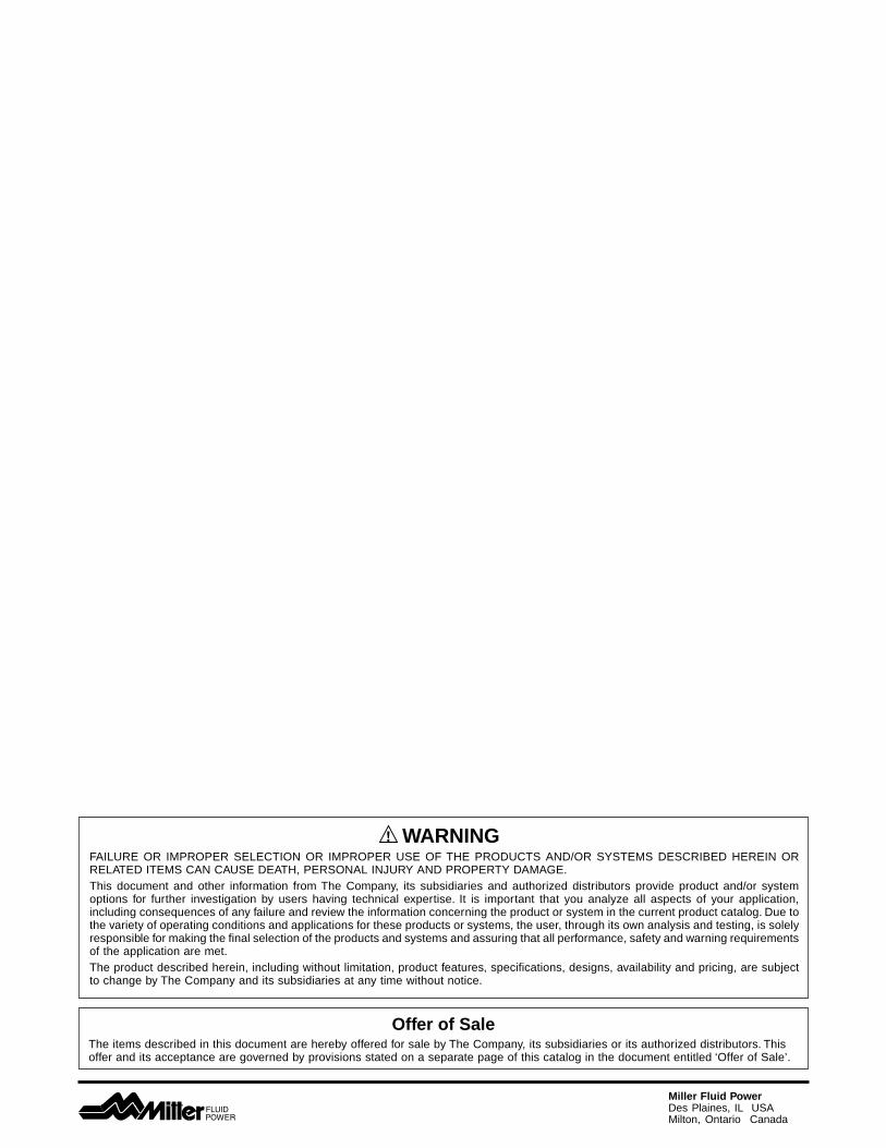
Complete accessory programThe Series P1D offers a complete ISO, VDMA and AFNORcompatible accessory program, with a wide range of pistonrod and cylinder mountings for both pivoted and fixedoperation. Several of these types of mountings are availablein stainless steel. The new “drop-in” sensors are availablewith both reed and solid-state operation, with a wide rangeof connector types and cable lengths.
New, mechanically protected sensor technologyThe body extrusion has recessed sensor grooves on threesides of the cylinder. The new sensors drop into the sensorgroove quickly and easily. Both the cable and the sensorare protected. Choose a sensor with 3 or 10 m cable, 8 mmconnector or the new M12 connector.
Optimized cushioningThanks to the composite inserts in the end covers, eachcylinder bore has been given individual flow geometry. Thisprovides optimized cushioning, which is quicker and easierto set and adjust.
Smooth, quiet operation and long service lifeAll seals and end-of-stroke bumpers are made frompolyurethane (PUR), the bearings and piston are made fromproven engineered composite material with excellentbearing properties and all cylinders are greased at thefactory with a transparent, food-grade grease. Altogetherthis gives the Series P1D very long service life and smooth,quiet operation.

Pneumatic CylindersSeries P1D
6Miller Fluid PowerDes Plaines, IL USAMilton, Ontario Canada
Catalog M0926
P1D Removable Gland Version
P1D Removable Gland VersionThe Removable Gland Version of the P1D hasprecision, lightweight aluminum end caps for thoseapplications that require a more robust design. Thisversion also offers a removable rod gland allowing forcomplete replacement of rod seals and/or rod bearingwithout disassembly.
High technology designStill based on the standard P1D design, you can cus-tomize your cylinder to the application with options ofa high strength composite piston or a robust aluminumpiston that contains a wear-band, which eliminates anymetal-to-metal contact. Both pistons come standardwith a magnet for optional use of cylinder sensors.
Common design platformThe Removable Gland Version of the P1D has thesame technical platform as the standard P1D. The bestmaterials (e.g. – PTFE filled Bronze Rod Gland),manufacturing methods and the careful attention todetail give the P1D Removable Gland Version smooth,quiet operation and long service.
Installation dimensions according tointernational standardsThe Removable Gland Version of the P1D complieswith the current ISO 6431, ISO/DIS 15552, VDMA24562 and AFNOR installation dimensional standardsfor customer reassurance world-wide.

Pneumatic CylindersSeries P1D
7Miller Fluid PowerDes Plaines, IL USAMilton, Ontario Canada
Catalog M0926
P1D Removable Gland Version
Removable GlandAn extra-long inboard bearing surface ensures lubricationfrom within the cylinder. Outboard of the bearing are twoleak-proof seals. The rod wiper seal wipes away any dirton the rod. This means less wear on bearing surfaces andinternal parts. The result is positive, no-leak sealing,regardless of conditions. And with the famous Millerremovable style gland, you can replace the rod sealsand/or bearings when necessary without disassemblingthe rest of the cylinder and without the need of anyspecial wrenches.
Aluminum Piston OptionFor high temperature applications, an aluminum piston isavailable with fluorocarbon seals. The piston is threadedonto the piston rod and secured in place with anaerobicadhesive which is temperature sensitive. For applicationsabove +121°C (+250°F) specify a pinned piston to rodconnection. The polyurethane seals that are standard onthe nylon piston are also an available option with thealuminum piston. The magnet that is cleverly hiddenunderneath the wear-band is also a standard feature onthe aluminum piston. The durable wear-band preventsany metal-to-metal contact between the piston and thecylinder body wall increasing the overall life of thecylinder.
Machined End Caps with Captive CushionScrew AdjustmentThe end caps on the Removable Gland Version of theP1D are made of precision lightweight aluminum. Thisallows for maximum flexibility and quick response for anycustomization that is required. The end caps also featurea captive cushion needle valve adjustment screw foroptimized cushioning that is inherent throughout the P1Dfamily of ISO cylinders.

Pneumatic CylindersSeries P1D
8Miller Fluid PowerDes Plaines, IL USAMilton, Ontario Canada
P1D Clean VersionThe P1D Clean version is a new addition to our ISOcylinder system, completely designed for the foodindustry. Many years’ experience of the stringentrequirements for hygiene regarding choice of materialand corrosion resistance have guided the developmentof this cylinder version. Great emphasis has been puton careful design of the external parts of the cylinder,including choice of materials and corrosion protection.
Main dimensions according tointernational standardsAll the main dimensions of the P1D Clean comply withISO 6431, ISO/DIS 1555, VDMA 24562 and AFNORstandards. The exception is the somewhat largerfootprint of the end covers and envelope of the bodyextrusion, due to the hygienic, convex, easy-to-cleangeometry of the cushioning adjustment screw and thecomponents of the integrated sensor system.
Common, high technology design platformThe P1D Clean version has the same technicalplatform as the standard P1D. The best materials,manufacturing methods and the careful attention todesign detail give the P1D Clean Version smooth,quiet operation and long service life.
Convex shape for optimum hygieneWhat makes the P1D Clean version unique is itsconvex body extrusion, which allows the cylinder to bekept clean. Regardless of orientation, fluids will run offthe cylinder body surfaces.
Catalog M0926
P1D Clean Version

Pneumatic CylindersSeries P1D
9Miller Fluid PowerDes Plaines, IL USAMilton, Ontario Canada
Cushioning screw with positive geometryTo offer the best hygiene properties, the projectingcushioning screw is sealed against the end cover. Thiseliminates dirt-collecting cavities and gives the besthygiene, since it is so easy to clean.
Sealing plugsPlastic sealing plugs are supplied with every CleanVersion of the P1D cylinder. These are installed in theend cover screws which are not used for the cylinderinstallation. To ensure the sealing function, the plugscan be used only once, i.e. they cannot be re-used.When installed in the end cover screws, they aretapped lightly with a hammer for high axial force.
Patent applied for system of integratedstandard sensorsThe Clean Version of the P1D cylinder has a system ofsensors, which are fully integrated into the bodyextrusion to give the cylinders a clean external design.Up to four sensors chosen from the range of P1Dstandard sensors, can be mounted in two dedicatedgrooves beneath a transparent, sealed molding.Tightening the stop screw onto the cam shaft will lockeach sensor in the desired position. The sensor LEDsare always fully visible, which facilitates initial set-up,adjustment and trouble-shooting. The entire sensorsystem has a hose-proof design equivalent to IP65.
Up to four integral sensorsCylinders for two integral sensors have two undividedcamshafts along the entire stroke. Free choice of cableexit, front or rear. There is also a version with dividedcamshafts for up to four sensors, which are installedtwo from each end cover, with cable exiting both frontand rear.
The sensor position is easily adjusted byundoing a set screw and using the cableto move the sensor to the desiredposition.
Simple sensor adjustmentThe sensors are mounted into theirgrooves through the opening in atransparent, sealed cover. The sensorcables have strain relief and are sealed.
Once the sensor has been locked in itsnew position, the protective cover isinstalled again.
Catalog M0926
P1D Clean Version
Pneumatic CylindersSeries P1D
10Miller Fluid PowerDes Plaines, IL USAMilton, Ontario Canada
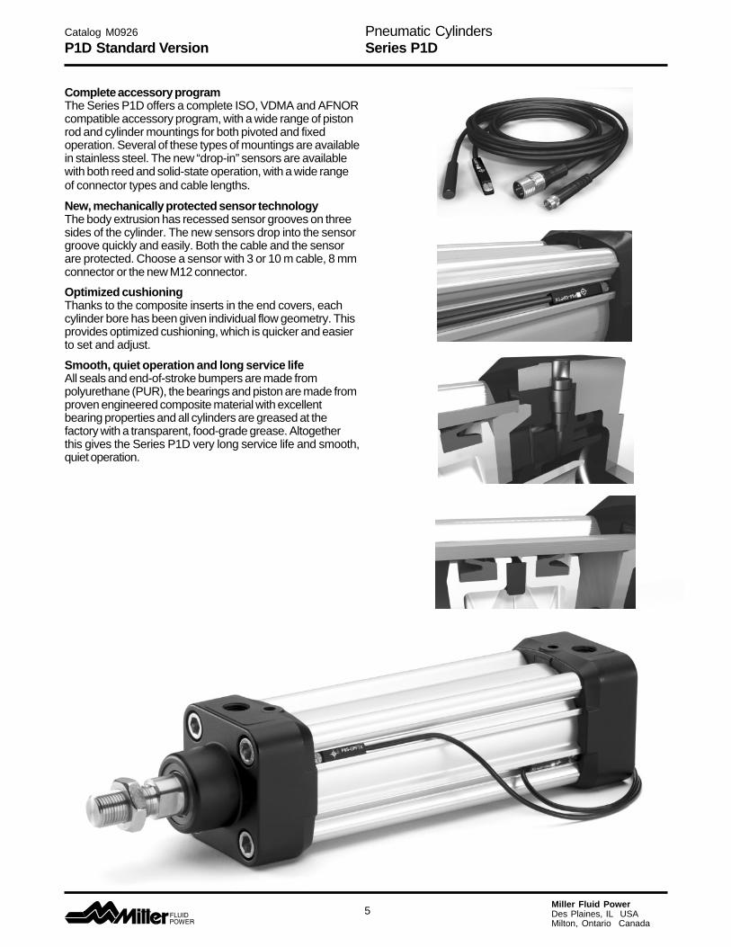
P1D Tie-Rod VersionThe Series P1D is also available in a tie-rod version,based on the same high level technology. This cylinderis the perfect choice wherever a true tie-rod cylinder isneeded.
Installation dimensions to international standardThe P1D Tie-Rod version complies with ISO 6431,ISO/DIS 15552, VDMA 24562 and AFNOR installationdimension standards, for customer reassuranceworld-wide.
Smooth, quiet operation and long service lifeAll seals and end-of-stroke bumpers are made frompolyurethane (PUR), the bearings and piston are madefrom proven engineered composite material withexcellent bearing properties and the initial greasing atthe factory with a transparent, food-grade grease.Altogether this gives the P1D very long service life andgentle, quiet operation.
Optimized cushioningThanks to the composite inserts in the end covers,each cylinder bore has been given an individual flowgeometry. This gives an optimized cushioning, which isquicker and easier to set and adjust.
Complete accessory programThe P1D offers a complete ISO, VDMA and AFNORcompatible accessory program, with a wide range ofpiston rod and cylinder mountings for both pivoted andfixed operation.
“Drop-in” sensorThe P1D Tie-Rod utilizes the same global drop-insensors as the Standard and Clean versions. Aningenious multi-jointed adapter joins the sensors to thetie rod in any chosen position along the stroke.
Catalog M0926
P1D Tie Rod Version

Pneumatic CylindersSeries P1D
11Miller Fluid PowerDes Plaines, IL USAMilton, Ontario Canada
Design variantsUsing P1D cylinders as a platform, a number of differentdesigns can be produced to suit differing requirements.Please refer to the “How to Order” section for thedesignation of each variant.
High ambient temperatureFor all bores, Ø32-125 mm, the P1D can be supplied inspecial high ambient temperature version. The cylindershave seal systems, materials and grease for elevatedtemperature ranges. The high temperature version does nothave a magnetic piston (no function at high temperatures).The aluminum piston option is required for service above+80°C (+176°F) and a pinned piston to rod connection isrequired for service above +121°C (+250°F).Ambient temperature range:– -10°C to +121°C, peaks up to +150°C
(+14°F to +250°F, peaks up to +300°F).
Alternative piston rod materialsAll P1D cylinders in all bores, Ø32-125 mm, can beordered with the following piston rod materials:– Steel, hard chrome plated (standard)– Stainless steel, hard chrome plated– Acid proof steel
Double Rod CylindersAll P1D cylinders in all bores, Ø32-125 mm, are availablewith a double rod, or through rod.
Cylinders with a double rod can take higher side forcesthanks to the double support for the piston rod. In addition,this design makes it easier to install external mechanicalposition sensors as well as giving equal force and flow onboth sides of the piston.
Low pressure hydraulicsThe P1D in bores Ø32 - 125 mm can be supplied withspecial seals for operation with low pressure hydraulics upto 10 bar. Temperature range -20°C to +80°C (-4°F to+176°F).
3 and 4 position cylindersBy installing two cylinders with the same or differentstroke, it is possible to build a working unit with three orfour positions. This type of unit is available as factory-fitted P1D Tie-Rod Version cylinders in all bores, Ø32-125mm. Other P1D cylinders can be flange mounted back-to-back with a special mounting.
Tandem versionThe P1D is also available as a tandem cylinder, i.e. twocylinders connected in series. This cylinder unit hasalmost twice the force, which is a great advantage inrestricted spaces. Tandem cylinders are available astie-rod style cylinders in all bores Ø32-125 mm.
Catalog M0926
Cylinder Options
Double Rod
3 and 4 Position Cylinders
Tandem Cylinders
High Ambient Temperature
Alternative Piston Rod Materials
Pneumatic CylindersSeries P1D
12Miller Fluid PowerDes Plaines, IL USAMilton, Ontario Canada
ConnectionThe signal air for the locking device can be obtaineddirectly from a main air supply, or from the air supplyserving the valve that controls the cylinder itself. Forcontrolled ON/OFF operation of the locking device, aseparate quick–venting valve is used.
The piston rod should not be moving when the lockingdevice is activated. The locking device is not intended tobrake a movement in repeated sequences.
Holding Forces
Catalog M0926
Features/Holding Forces
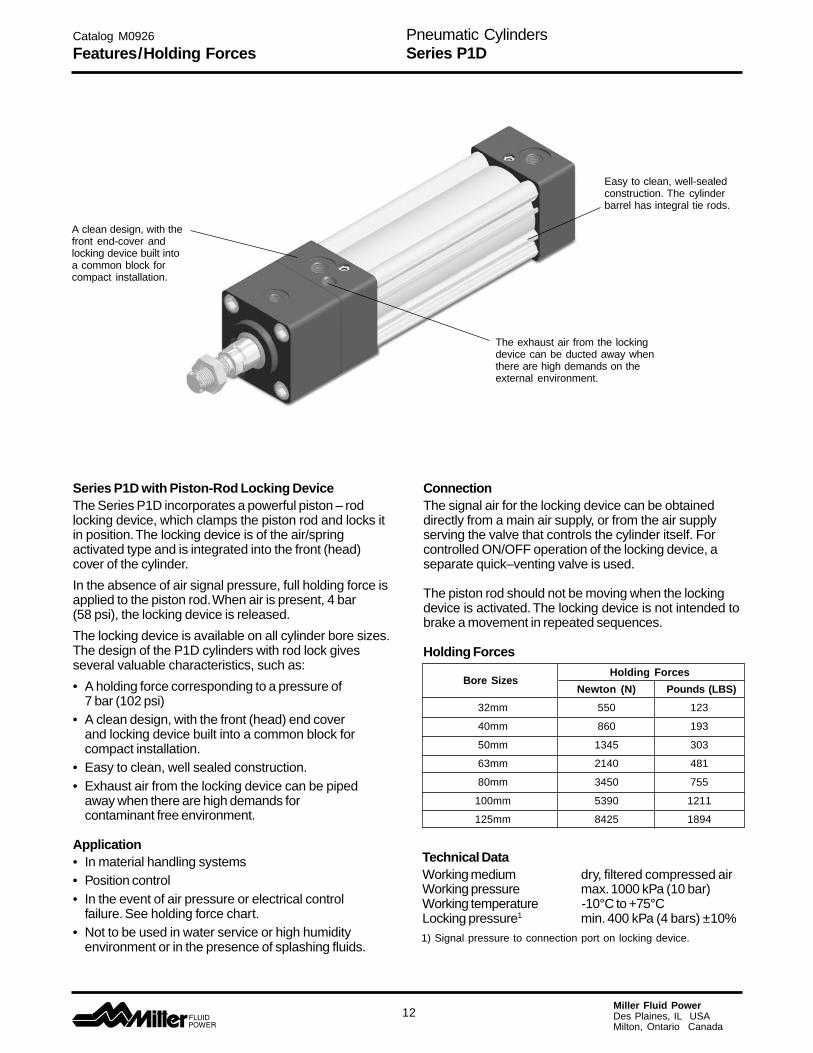
Series P1D with Piston-Rod Locking DeviceThe Series P1D incorporates a powerful piston – rodlocking device, which clamps the piston rod and locks itin position. The locking device is of the air/springactivated type and is integrated into the front (head)cover of the cylinder.
In the absence of air signal pressure, full holding force isapplied to the piston rod. When air is present, 4 bar(58 psi), the locking device is released.
The locking device is available on all cylinder bore sizes.The design of the P1D cylinders with rod lock givesseveral valuable characteristics, such as:
• A holding force corresponding to a pressure of7 bar (102 psi)
• A clean design, with the front (head) end coverand locking device built into a common block forcompact installation.
• Easy to clean, well sealed construction.• Exhaust air from the locking device can be piped
away when there are high demands forcontaminant free environment.
Application• In material handling systems• Position control• In the event of air pressure or electrical control
failure. See holding force chart.• Not to be used in water service or high humidity
environment or in the presence of splashing fluids.
Technical DataWorking medium dry, filtered compressed airWorking pressure max. 1000 kPa (10 bar)Working temperature -10°C to +75°CLocking pressure1 min. 400 kPa (4 bars) ±10%1) Signal pressure to connection port on locking device.
Bore SizesHolding Forces
Newton (N) Pounds (LBS)
32mm 550 123
40mm 860 193
50mm 1345 303
63mm 2140 481
80mm 3450 755
100mm 5390 1211
125mm 8425 1894
A clean design, with thefront end-cover andlocking device built intoa common block forcompact installation.
The exhaust air from the lockingdevice can be ducted away whenthere are high demands on theexternal environment.
Easy to clean, well-sealedconstruction. The cylinderbarrel has integral tie rods.
Pneumatic CylindersSeries P1D
13Miller Fluid PowerDes Plaines, IL USAMilton, Ontario Canada
12
8
4VD
A
L
P
WH
L + S
H
ØD
T
STT
SS
ØBA
KK
ØD
ØB
AM L
BG
EE
VAG
PLPP
OA
RT
R
E
6G1/8
DIN 439BSW
(M5 Ø32 - Ø40)G 1/8 Ø50 - Ø125)
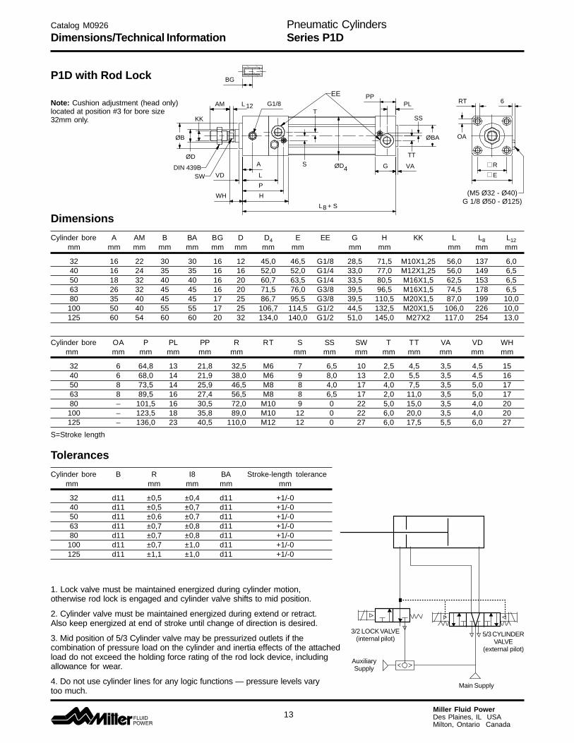
Note: Cushion adjustment (head only)located at position #3 for bore size32mm only.
Catalog M0926
Dimensions/Technical Information
Dimensions
Cylinder bore A AM B BA BG D D4 E EE G H KK L L8 L12 mm mm mm mm mm mm mm mm mm mm mm mm mm mm
32 16 22 30 30 16 12 45,0 46,5 G1/8 28,5 71,5 M10X1,25 56,0 137 6,0 40 16 24 35 35 16 16 52,0 52,0 G1/4 33,0 77,0 M12X1,25 56,0 149 6,5 50 18 32 40 40 16 20 60,7 63,5 G1/4 33,5 80,5 M16X1,5 62,5 153 6,5 63 26 32 45 45 16 20 71,5 76,0 G3/8 39,5 96,5 M16X1,5 74,5 178 6,5 80 35 40 45 45 17 25 86,7 95,5 G3/8 39,5 110,5 M20X1,5 87,0 199 10,0
100 50 40 55 55 17 25 106,7 114,5 G1/2 44,5 132,5 M20X1,5 106,0 226 10,0 125 60 54 60 60 20 32 134,0 140,0 G1/2 51,0 145,0 M27X2 117,0 254 13,0
Cylinder bore OA P PL PP R RT S SS SW T TT VA VD WH mm mm mm mm mm mm mm mm mm mm mm mm mm mm
32 6 64,8 13 21,8 32,5 M6 7 6,5 10 2,5 4,5 3,5 4,5 15 40 6 68,0 14 21,9 38,0 M6 9 8,0 13 2,0 5,5 3,5 4,5 16 50 8 73,5 14 25,9 46,5 M8 8 4,0 17 4,0 7,5 3,5 5,0 17 63 8 89,5 16 27,4 56,5 M8 8 6,5 17 2,0 11,0 3,5 5,0 17 80 – 101,5 16 30,5 72,0 M10 9 0 22 5,0 15,0 3,5 4,0 20
100 – 123,5 18 35,8 89,0 M10 12 0 22 6,0 20,0 3,5 4,0 20 125 – 136,0 23 40,5 110,0 M12 12 0 27 6,0 17,5 5,5 6,0 27
S=Stroke length
Tolerances
Cylinder bore B R I8 BA Stroke-length tolerance mm mm mm mm mm
32 d11 ±0,5 ±0,4 d11 +1/-0 40 d11 ±0,5 ±0,7 d11 +1/-0 50 d11 ±0,6 ±0,7 d11 +1/-0 63 d11 ±0,7 ±0,8 d11 +1/-0 80 d11 ±0,7 ±0,8 d11 +1/-0
100 d11 ±0,7 ±1,0 d11 +1/-0 125 d11 ±1,1 ±1,0 d11 +1/-0
1. Lock valve must be maintained energized during cylinder motion,otherwise rod lock is engaged and cylinder valve shifts to mid position.
2. Cylinder valve must be maintained energized during extend or retract.Also keep energized at end of stroke until change of direction is desired.
3. Mid position of 5/3 Cylinder valve may be pressurized outlets if thecombination of pressure load on the cylinder and inertia effects of the attachedload do not exceed the holding force rating of the rod lock device, includingallowance for wear.
4. Do not use cylinder lines for any logic functions — pressure levels varytoo much.
3/2 LOCK VALVE(internal pilot)
AuxiliarySupply
Main Supply
5/3 CYLINDERVALVE
(external pilot)
P1D with Rod Lock

Pneumatic CylindersSeries P1D
14Miller Fluid PowerDes Plaines, IL USAMilton, Ontario Canada
AMØ
B
ØD
KK
BG
VD
G
WH
WH WH + S
L2
L12
ØD
4
PP
PL
SS
TT Ø
BA
VA
GL8 + S
RT
OA
R
E
L9 + 2 x S
DIN 439B
SW
EE
P1D Standard Version
Catalog M0926
Dimensions P1D Standard Version
Dimensions
Cylinder bore AM B BA BG D D4 E EE G KK L2 L8 L9 L12mm mm mm mm mm mm mm mm mm mm mm mm mm
32 22 30 30 16 12 45,0 50,0 G1/8 28,5 M10x1,25 16,0 94 146 6,040 24 35 35 16 16 52,0 57,4 G1/4 33,0 M12x1,25 19,0 105 165 6,550 32 40 40 16 20 60,7 69,4 G1/4 33,5 M16x1,5 24,0 106 180 8,063 32 45 45 16 20 71,5 82,4 G3/8 39,5 M16x1,5 24,0 121 195 8,080 40 45 45 17 25 86,7 99,4 G3/8 39,5 M20x1,5 30,0 128 220 10,0
100 40 55 55 17 25 106,7 116,0 G1/2 44,5 M20x1,5 32,4 138 240 10,0125 54 60 60 20 32 134,0 139,0 G1/2 51,0 M27x2 45,0 160 290 13,0
Cylinder bore OA PL PP R RT SS SW TT VA VD WHmm mm mm mm mm mm mm mm mm mm mm
32 6 13 21,8 32,5 M6 4,0 10 4,5 3,5 4,5 2640 6 14 21,9 38,0 M6 8,0 13 5,5 3,5 4,5 3050 8 14 25,9 46,5 M8 4,0 17 7,5 3,5 4,5 3763 8 16 27,4 56,5 M8 6,5 17 11,0 3,5 4,5 3780 6 16 30,5 72,0 M10 0 22 15,0 3,5 4,5 46
100 6 18 35,8 89,0 M10 0 22 20,0 3,5 4,5 51125 8 23 40,5 110,0 M12 0 27 17,5 5,5 6,5 65S=Stroke
Tolerances
Cylinder bore B BA L8 L9 R Stroke tolerancemm mm mm mm mm
32 d11 d11 ±0,4 ±2 ±0,5 +1/-040 d11 d11 ±0,7 ±2 ±0,5 +1/-050 d11 d11 ±0,7 ±2 ±0,6 +1/-063 d11 d11 ±0,8 ±2 ±0,7 +1/-080 d11 d11 ±0,8 ±3 ±0,7 +1/-0
100 d11 d11 ±1,0 ±3 ±0,7 +1/-0125 d11 d11 ±1,0 ±3 ±1,1 +1/-0
Pneumatic CylindersSeries P1D
15Miller Fluid PowerDes Plaines, IL USAMilton, Ontario Canada
AM L12
ØB
ØD KK
DIN 439B
SW
VD
L2 G
WH L + S8
G
VAØD4
ØBA
PL
PP
EE OA
RT
E
R
BG
WH
L + 2 x S
WH + S
9
SS
TT
Dimensions
Cylinder bore AM B BA BG D D4 E EE G KK L2 L8 L9 L12mm mm mm mm mm mm mm mm mm mm mm mm mm
32 22 30 30 16 12 45,0 46,5 G1/8 28,5 M10x1,25 18 94 146 6,040 24 35 35 16 16 52,0 52,0 G1/4 33,0 M12x1,25 20 105 165 6,550 32 40 40 16 20 60,7 63,5 G1/4 33,5 M16x1,5 26 106 180 6,563 32 45 45 16 20 71,5 76,0 G3/8 39,5 M16x1,5 26 121 195 6,580 40 45 45 17 25 86,7 95,5 G3/8 39,5 M20x1,5 33 128 220 10,0
100 40 55 55 17 25 106,7 114,5 G1/2 44,5 M20x1,5 33 138 240 10,0125 54 60 60 20 32 134,0 140,0 G1/2 51,0 M27x2 41 160 290 13,0
Cylinder bore OA PL PP R RT SS SW TT VA VD WHmm mm mm mm mm mm mm mm mm mm mm
32 6 13 21,8 32,5 M6 6,5 10 4,5 3,5 4,5 2640 6 14 21,9 38,0 M6 8,0 13 5,5 3,5 4,5 3050 8 14 25,9 46,5 M8 4,0 17 7,5 3,5 4,5 3763 8 16 27,4 56,5 M8 6,5 17 11,0 3,5 4,5 3780 6 16 30,5 72,0 M10 0 22 15,0 3,5 4,5 46
100 6 18 35,8 89,0 M10 0 22 20,0 3,5 4,5 51125 8 23 40,5 110,0 M12 0 27 17,5 5,5 6,5 65S=Stroke
Tolerances
Cylinder bore B BA L8 L9 R Stroke tolerancemm mm mm mm mm
32 d11 d11 ±0,4 ±2 ±0,5 +1/-040 d11 d11 ±0,7 ±2 ±0,5 +1/-050 d11 d11 ±0,7 ±2 ±0,6 +1/-063 d11 d11 ±0,8 ±2 ±0,7 +1/-080 d11 d11 ±0,8 ±3 ±0,7 +1/-0
100 d11 d11 ±1,0 ±3 ±0,7 +1/-0125 d11 d11 ±1,0 ±3 ±1,1 +1/-0
Catalog M0926
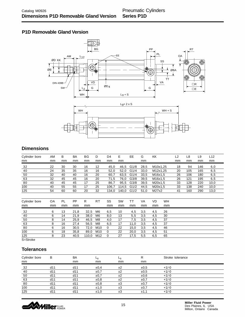
Dimensions P1D Removable Gland Version
P1D Removable Gland Version

Pneumatic CylindersSeries P1D
16Miller Fluid PowerDes Plaines, IL USAMilton, Ontario Canada
AM
ØB
ØD
KK
VD
G
WH
L2
L12
PPE2 maxPL
SS
TT Ø
BA
VA
GL8 + S
RT
OA
R
E
E 1
DIN 439B
SW
EE
ØD
7
AM
ØB
ØD
KK
VD
G
WH
L2
L12
ØD
5
ØD
6
PP
PL
SS
TT Ø
BA
VAG
L8 + S
RT
OA
R
E
DIN 439B
SW
EE
Dimensions
Cylinder boreD5 D6 D7 E1 E2max
mm mm mm mm mm mm
32 36 5,3 49,6 32 540 45 5,3 57,3 36 650 55 7,1 69,3 42 663 68 7,1 82,3 49 580 85 8,9 99,3 57 5
100 105 8,9 117,6 68 6125 132 10,7 142,8 81 6
Other dimensions, see page 14.
P1D Tie-Rod Version
P1D Clean Version
Catalog M0926
Dimensions P1D Clean and Tie Rod Versions
Pneumatic CylindersSeries P1D
17Miller Fluid PowerDes Plaines, IL USAMilton, Ontario Canada
Specifications
Cylinder Cylinder Piston rod Cushioning Air con- Connectiondesignation bore area dia. area thread length sump- thread
tion2)
mm cm2 mm cm2 mm litre
P1D-•032••-XXXX1) 32 8,0 12 1,1 M10x1,25 17 0,105 G1/8P1D-•040••-XXXX1) 40 12,6 16 2,0 M12x1,25 19 0,162 G1/4P1D-•050••-XXXX1) 50 19,6 20 3,1 M16x1,5 20 0,253 G1/4P1D-•063••-XXXX1) 63 31,2 20 3,1 M16x1,5 23 0,414 G3/8P1D-•080••-XXXX1) 80 50,3 25 4,9 M20x1,5 23 0,669 G3/8P1D-•100••-XXXX1) 100 78,5 25 4,9 M20x1,5 27 1,043 G1/2P1D-•125••-XXXX1) 125 122,7 32 8,0 M27x2 30 1,662 G1/2
Cylinder Total mass (kg) Total mass (kg) Mass moving components (kg)designation at 0 mm stroke Supplement per at 0 mm Supplement per
10 mm stroke stroke 10 mm strokeStandard Tie-Rod Clean Standard Tie-Rod Clean All variants All variants
P1D-•032••-XXXX1) 0,55 0,54 0,60 0,023 0,022 0,047 0,13 0,009P1D-•040••-XXXX1) 0,80 0,79 0,88 0,033 0,030 0,063 0,24 0,016P1D-•050••-XXXX1) 1,20 1,20 1,32 0,048 0,048 0,094 0,42 0,025P1D-•063••-XXXX1) 1,73 1,73 1,86 0,051 0,051 0,101 0,50 0,025P1D-•080••-XXXX1) 2,45 2,47 2,63 0,075 0,079 0,142 0,90 0,039P1D-•100••-XXXX1) 4,00 4,00 4,22 0,084 0,084 0,168 1,10 0,039P1D-•125••-XXXX1) 6,87 6,73 7,01 0,138 0,129 0,248 2,34 0,063
1) Stroke2) Free air consumption per 10 mm stroke for a double stroke at 6 bar
Operation dataWorking pressure Max 10 barWorking temperature min maxStandard -20°C (-4°F) +80°C (+176°F)High temp version -10°C (+14°F) +121°C (+250°F)
Aluminum piston is required for service above +80°C (+176°F)Greased for life, does not normally need additional lubrication. Iflubrication is given, this must always be continued.
Bores and strokesP1D 32 - 125 mmMax stroke 2800 mmMin stroke, P1D Clean 25 mm
Cylinder forcesThe values for cylinder forces are theoretical, and should bereduced to suit working conditions.
Cylinder Cylinder Theoretical cylinder forcedesignation bores at 6 bar
extend stroke retract strokemm N N
P1D-•032••-XXXX3) 32 482 414P1D-•040••-XXXX3) 40 754 633P1D-•050••-XXXX3) 50 1178 989P1D-•063••-XXXX3) 63 1870 1681P1D-•080••-XXXX3) 80 3016 2721P1D-•100••-XXXX3) 100 4712 4417P1D-•125••-XXXX3) 125 7363 6880
3) XXXX = stroke• = optional design in accordance with order key
P1D Clean VersionProtection class Tube-proof in accordance with IP65Chemical resistance Tested for normally used industrial
detergents, both acid and alkaline
Working medium, air qualityWorking medium Dry, filtered compressed air
to ISO 8573-1 class 3. 4. 3. or better
Recommended air quality for cylinders
For best possible service life and trouble-free operation, ISO 8573-1quality class 3.4.3 should be used. This means 5 µm filter (standardfilter) dew point +3°C (+37°F) for indoor operation (a lower dew pointshould be selected for outdoor operation) and oil concentration 1.0mg oil/m3, which is what a standard compressor with a standardfilter gives.
ISO 8573-1 quality classes
Quality Pollution Water Oilclass particle max con- max. press. max con-
size centration dew point centration (µm) (mg/m³) (°C) (°F) (mg/m³)
1 0,1 0,1 -70 -94 0,012 1 1 -40 -40 0,13 5 5 -20 -4 1,04 15 8 +3 +37 5,05 40 10 +7 +44 256 - - +10 +50 -
Catalog M0926
General Specifications

Pneumatic CylindersSeries P1D
18Miller Fluid PowerDes Plaines, IL USAMilton, Ontario Canada
Catalog M0926
Material Specification and Cushioning Diagram
4,0
3,0
2,0
1,5
1,0
0,50,4
0,3
0,2
0,11 2 3 4 5 10 20 30 40 50 100 200 300 500 1000 2000
Ø32Ø40 Ø50
Ø63Ø80
Ø100Ø125
Speed [m/s]
Mass [kg]
Material specificationStandard designBody extrusion Clear anodized aluminumEnd cover Powder coated or black anodized Al.End cover inserts POMEnd cover nuts/screws Zinc plated steel 8.8Piston rod nut Zinc plated steelPiston rod Chrome-plated steelScraper ring PURPiston rod bearing POMPiston POMPiston bearing POMMagnetic ring Bound magnetic materialPiston bolt Zinc plated steelPiston seal PURO-rings Nitrile rubber, NBREnd-of-stroke washers PURCushioning seals PURCushioning screws PA
P1D CleanTransparent molding SiliconeTransparent cover ABSScrews, sensor system Stainless steelUpper seal, cover EPDMLower seal, cover Foam rubberSealing plugs PAPiston rod nut Stainless steel
P1D Tie-RodTie-rods Stainless steel
Design variantsHigh temperature design
Seals/scraper ring Fluorocarbon rubberPiston Anodized aluminumPiston/piston rod bearing PTFE filled bronze
Low pressure hydraulicsSeals/scraper ring Nitrile rubber, NBRPiston Anodized aluminumPiston/piston rod bearing UHMWPE plastic
OptionPiston rod material Acid-proof steel
Hard-chromium plated stainless steel
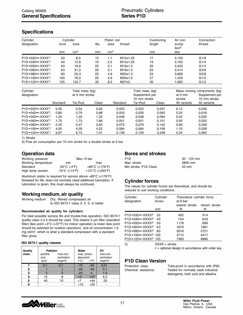
Cushioning characteristicsThe diagram below is used for sizing of cylinders related tothe cushioning capacity. The maximum cushioning capacityshown in the diagram assumes the following:
• Low load, i.e. low pressure drop across the piston• Equilibrium speed• Correctly adjusted cushioning screw• 6 bar at cylinder port
The load is the sum of internal and external friction, plus anygravitational forces. At high relative load (pressure dropexceeding 1 bar), we recommend that for any given speed,the mass should be reduced by a factor of 2.5, or for a givenmass, the speed should be reduced by a factor of 1.5. This isin relation to the maximum performance given in thediagram.

Pneumatic CylindersSeries P1D
19Miller Fluid PowerDes Plaines, IL USAMilton, Ontario Canada
1) The “equivalent throttling bore” is a long throttle (for example a tube) or a series of throttles (for example, through a valve)converted to a short throttle which gives a corresponding flow rate. This should not be confused with the “orifice” which issometimes specified for valves. The value for the orifice does not normally take account of the fact that the valve containsa number of throttles.
2) Qn is a measure of the valve flow capacity, with flow measured in litre per minute (l/min) at 6 bar(e) supply pressure and1 bar pressure drop across the valve.
Guide for selecting suitable tubingThe selection of the correct size of tubing is often basedon experience, with no great thought to optimizingenergy efficiency and cylinder velocity. This is usuallyacceptable, but making a rough calculation can result inworthwhile economic gains.
The following is the basic principle:1. The primary line to the working valve could be over
sized (this does not cause any extra air consumptionand consequently does not create any extra costs inoperation).
2. The tubes between the valve and the cylinder should,however, be optimized according to the principle thatan insufficient bore throttles the flow and thus limitsthe cylinder speed, while an oversized pipe creates adead volume which increases the air consumptionand fillingtime.
The chart below is intended to help when selecting thecorrect size of tube to use between the valve and thecylinder.
The following prerequisites apply:The cylinder load should be about 50% of thetheoretical force (= normal load). A lower load givesa higher velocity and vice versa. The tube size isselected as a function of the cylinder bore, the desiredcylinder velocity and the tube length between the valveand the cylinder.
If you want to use the capacity of the valve to itsmaximum, and obtain maximum speed, the tubingshould be chosen so that they at least correspond withthe equivalent restriction diameter (see descriptionbelow), so that the tubing does not restrict the totalflow. This means that a short tubing must have at leastthe equivalent restriction diameter. If the tubing islonger, choose it from the table below. Straight fittingsshould be chosen for highest flow rates. (Elbow andbanjo fittings cause restriction.)
Catalog M0926
Guide for Tubing and Valve Selection
0,2 0,5 0,8 1,1 1,4 0 1 2 3 4 5 6 7 8 9 10
1
2
3
4
5
6
7
8
9
10
11
Ø10Ø16Ø20Ø25Ø32Ø40Ø50
Ø63
Ø80
Ø100
Ø125
14/11
–/12
–/13
–/14
–/15
–/16
12/10
10/8
8/6
6/45/34/2,7
CylinderØ [mm]
Equivalent throttling bore 1) TubeØOut./ØInt. [mm]
Length of tubing [m]Cylinder speed [m/s]
Sui
tabl
e va
lve
Qn2)
app
800
l/m
in
Sui
tabl
e va
lve
Qn2)
app
100
0 l/m
in
Sui
tabl
e ar
ea f
or v
alve
with
Qn2)
app
300
0 l/m
in
Pneumatic CylindersSeries P1D
20Miller Fluid PowerDes Plaines, IL USAMilton, Ontario Canada
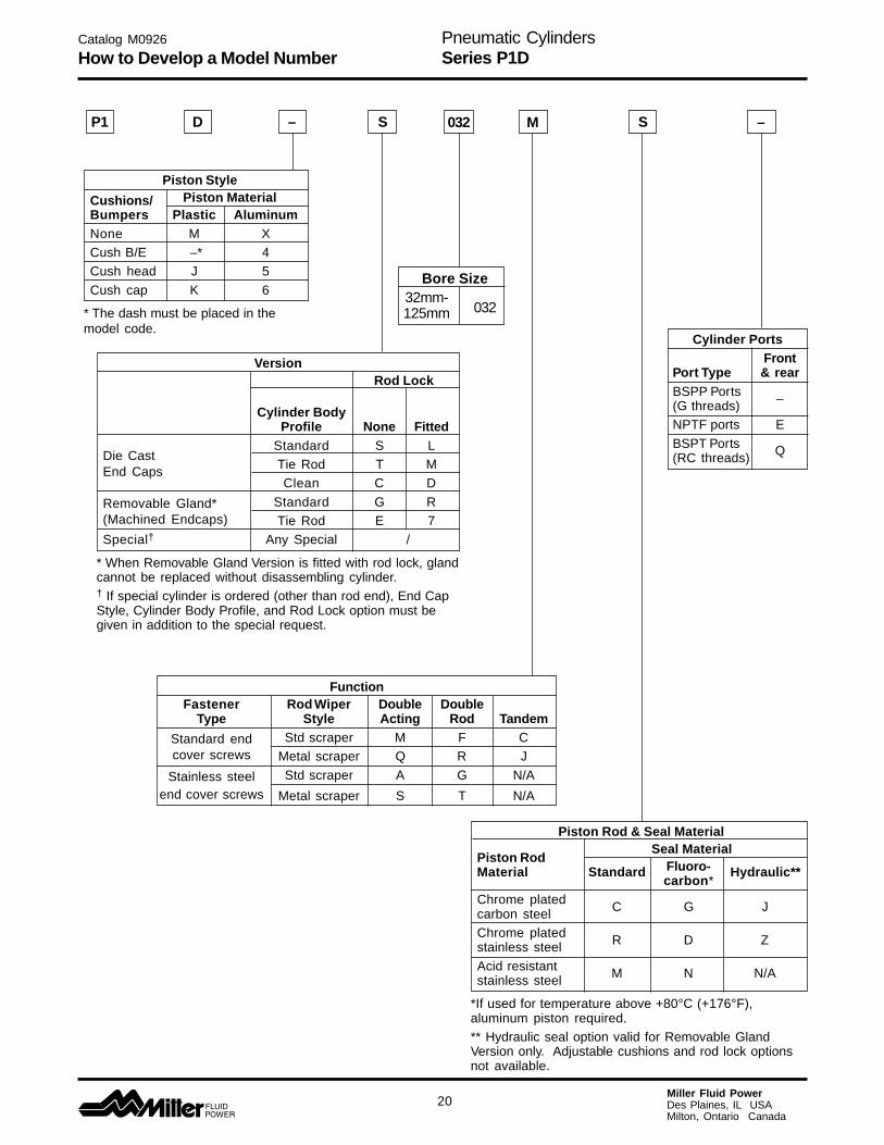
Piston Style
Cushions/ Piston MaterialBumpers Plastic AluminumNone M XCush B/E –* 4Cush head J 5
Cush cap K 6
* The dash must be placed in themodel code.
P1 D – S S
Catalog M0926
How to Develop a Model Number
Version Rod Lock
Cylinder BodyProfile None Fitted
Die CastStandard S L
End Caps Tie Rod T MClean C D
Removable Gland* Standard G R(Machined Endcaps) Tie Rod E 7Special† Any Special /
* When Removable Gland Version is fitted with rod lock, glandcannot be replaced without disassembling cylinder.† If special cylinder is ordered (other than rod end), End CapStyle, Cylinder Body Profile, and Rod Lock option must begiven in addition to the special request.
Bore Size32mm-125mm 032
FunctionFastener Rod Wiper Double Double
Type Style Acting Rod Tandem
Standard end Std scraper M F Ccover screws Metal scraper Q R J
Stainless steel Std scraper A G N/A
end cover screws Metal scraper S T N/A
Cylinder PortsFront
Port Type & rearBSPP Ports –(G threads)NPTF ports E
BSPT Ports Q(RC threads)
M –032
Piston Rod & Seal Material
Piston Rod Seal Material
Material Standard Fluoro- Hydraulic**carbon*
Chrome platedcarbon steel C G J
Chrome platedstainless steel R D Z
Acid resistantstainless steel M N N/A
*If used for temperature above +80°C (+176°F),aluminum piston required.** Hydraulic seal option valid for Removable GlandVersion only. Adjustable cushions and rod lock optionsnot available.
Pneumatic CylindersSeries P1D
21Miller Fluid PowerDes Plaines, IL USAMilton, Ontario Canada
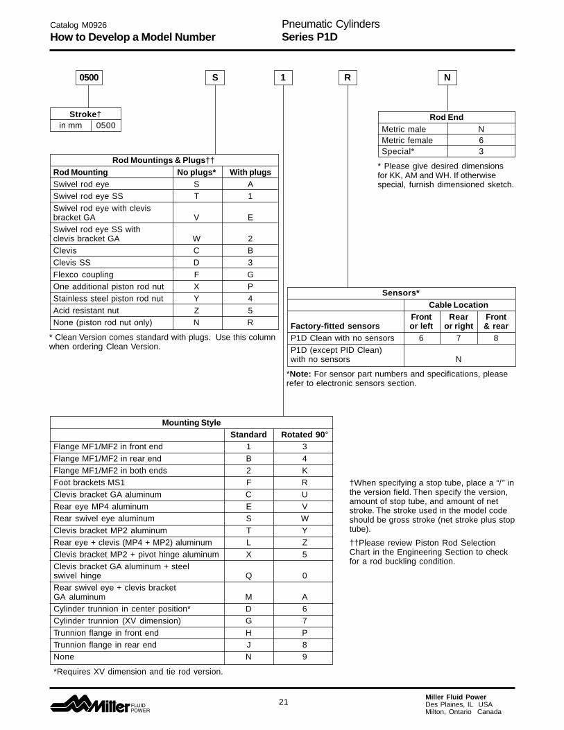
Rod Mountings & Plugs††
Rod Mounting No plugs* With plugsSwivel rod eye S ASwivel rod eye SS T 1
Swivel rod eye with clevisbracket GA V ESwivel rod eye SS with
` clevis bracket GA W 2Clevis C BClevis SS D 3
Flexco coupling F GOne additional piston rod nut X PStainless steel piston rod nut Y 4
Acid resistant nut Z 5None (piston rod nut only) N R
* Clean Version comes standard with plugs. Use this columnwhen ordering Clean Version.
Stroke†in mm 0500
Mounting StyleStandard Rotated 90°
Flange MF1/MF2 in front end 1 3
Flange MF1/MF2 in rear end B 4Flange MF1/MF2 in both ends 2 KFoot brackets MS1 F R
Clevis bracket GA aluminum C URear eye MP4 aluminum E VRear swivel eye aluminum S W
Clevis bracket MP2 aluminum T YRear eye + clevis (MP4 + MP2) aluminum L ZClevis bracket MP2 + pivot hinge aluminum X 5
Clevis bracket GA aluminum + steelswivel hinge Q 0Rear swivel eye + clevis bracketGA aluminum M ACylinder trunnion in center position* D 6Cylinder trunnion (XV dimension) G 7
Trunnion flange in front end H PTrunnion flange in rear end J 8None N 9
*Requires XV dimension and tie rod version.
Sensors*Cable Location
Front Rear FrontFactory-fitted sensors or left or right & rearP1D Clean with no sensors 6 7 8P1D (except PID Clean)with no sensors N
*Note: For sensor part numbers and specifications, pleaserefer to electronic sensors section.
Rod EndMetric male NMetric female 6Special* 3
* Please give desired dimensionsfor KK, AM and WH. If otherwisespecial, furnish dimensioned sketch.
Catalog M0926
How to Develop a Model Number
0500 S 1 R N
†When specifying a stop tube, place a “/” inthe version field. Then specify the version,amount of stop tube, and amount of netstroke. The stroke used in the model codeshould be gross stroke (net stroke plus stoptube).
††Please review Piston Rod SelectionChart in the Engineering Section to checkfor a rod buckling condition.

Pneumatic CylindersSeries P1D
22Miller Fluid PowerDes Plaines, IL USAMilton, Ontario Canada
Flange MF1/MF2
According to ISO MF1/MF2, VDMA 24 562, AFNOR
Cyl.- d1 FB TG1 E R MF TF UF l1 W ZF ZBbore H11 H13 JS14 JS14 JS14 -0,5mm mm mm mm mm mm mm mm mm mm mm mm mm
32 30 7 32,5 45 32 10 64 80 5,0 16 130 123,540 35 9 38,0 52 36 10 72 90 5,0 20 145 138,550 40 9 46,5 65 45 12 90 110 6,5 25 155 146,563 45 9 56,5 75 50 12 100 120 6,5 25 170 161,580 45 12 72,0 95 63 16 126 150 8,0 30 190 177,5
100 55 14 89,0 115 75 16 150 170 8,0 35 205 192,5125 60 16 110,0 140 90 20 180 205 10,5 45 245 230,5
S = Stroke length
Foot bracket MS1
According to ISO MS1, VDMA 24 562, AFNOR
Cyl.- AB TG1 E TR AO AU AH l7 AT l9 SAbore H14 JS14 JS15 JS14mm mm mm mm mm mm mm mm mm mm mm mm
32 7 32,5 45 32 10 24 32 30 4,5 17,0 14240 9 38,0 52 36 8 28 36 30 4,5 18,5 16150 9 46,5 65 45 13 32 45 36 5,5 25,0 17063 9 56,5 75 50 13 32 50 35 5,5 27,5 18580 12 72,0 95 63 14 41 63 49 6,5 40,5 210
100 14 89,0 115 75 15 41 71 54 6,5 43,5 220125 16 110,0 140 90 22 45 90 71 8,0 60,0 250
S = Stroke length
Pivot bracket with rigid bearing
According to CETOP RP 107 P, VDMA 24 562, AFNOR
Cyl.- CK S5 K1 K2 G1 G2 EM G3 CA H6 R1bore H9 H13 JS14 JS14 JS14 JS15mm mm mm mm mm mm mm mm mm mm mm mm
32 10 6,6 38 51 21 18 25,5 31 32 8 10,040 12 6,6 41 54 24 22 27,0 35 36 10 11,050 12 9,0 50 65 33 30 31,0 45 45 12 13,063 16 9,0 52 67 37 35 39,0 50 50 12 15,080 16 11,0 66 86 47 40 49,0 60 63 14 15,0
100 20 11,0 76 96 55 50 59,0 70 71 15 19,0125 25 14,0 94 124 70 60 69,0 90 90 20 22,5
32 0,23 P1C-4KMB40 0,28 P1C-4LMB50 0,53 P1C-4MMB63 0,71 P1C-4NMB80 1,59 P1C-4PMB
100 2,19 P1C-4QMB125 3,78 P1C-4RMB
ØF
B
R
UF
Ød1 TF
E
TG1
ZB+S
MFMF
W
ZF+S
I1
5
G
¯CK
CA
G2
G3
1R1
H6
KK12
S¯
EM
SA+S
ØAB
AU AO
AT
E
TGI
IAH
TR
7
32 0,06* P1C-4KMF40 0,08* P1C-4LMF50 0,16* P1C-4MMF63 0,25* P1C-4NMF80 0,50* P1C-4PMF
100 0,85* P1C-4QMF125 1,48* P1C-4RMF
* Weight per item
Cylinder mountingsType Description Cyl. bore Weight Order code
Ø mm kg
Intended for fixed mounting of cylinder. Foot bracket can be fittedto front and rear end covers of cylinder.
MaterialsFoot bracket: Surface-treated steel, blackMounting screws acc. to DIN 912: Zinc-plated steel 8.8
Supplied in pairs with mounting screws for attachment to cylinder.
Intended for flexible mounting of cylinder. The pivot bracket can becombined with clevis bracket MP2.
MaterialsPivot bracket: Surface-treated aluminum, blackBearing: Sintered oil-bronze bushing
Intended for fixed mounting of cylinder. Flange can be fitted to frontor rear end cover of cylinder.MaterialsFlange: Surface-treated aluminum, blackMounting screws acc. to DIN 6912: Zinc-plated steel 8.8Supplied complete with mounting screws for attachment tocylinder.
32 0,06 P1C-4KMD40 0,08 P1C-4LMD50 0,15 P1C-4MMD63 0,20 P1C-4NMD80 0,33 P1C-4PMD
100 0,49 P1C-4QMD125 1,02 P1C-4RMD
Catalog M0926
Mountings

Pneumatic CylindersSeries P1D
23Miller Fluid PowerDes Plaines, IL USAMilton, Ontario Canada
Swivel eye bracket Intended for use together with clevis bracket GA
MaterialBracket: Surface-treated aluminum, blackSwivel bearing acc. to DIN 648K: Hardened steel
Supplied complete with mounting screws for attachment tocylinder.
According to VDMA 24 562, AFNOR
Cyl.- E B1 B2 EN R1 R2 FL l2 L CN XD Zbore H7mm mm mm mm mm mm mm mm mm mm mm mm
32 45 10,5 - 14 16 - 22 5,5 12 10 142 4°40 52 12,0 - 16 18 - 25 5,5 15 12 160 4°50 65 15,0 51 21 21 19 27 6,5 15 16 170 4°63 75 15,0 - 21 23 - 32 6,5 20 16 190 4°80 95 18,0 - 25 29 - 36 10,0 20 20 210 4°
100 115 18,0 - 25 31 - 41 10,0 25 20 230 4°125 140 25,0 - 37 40 - 50 10,0 30 30 275 4°
S = Stroke length
Clevis bracket MP2 Intended for flexible mounting of cylinder. Clevis bracketMP2 can be combined with clevis bracket MP4.
MaterialsClevis bracket: Surface-treated aluminum, blackPin: Surface hardened steelCirclips according to DIN 471: Spring steelMounting screws acc. to DIN 912: Zinc-plated steel 8.8
Supplied complete with mounting screws for attachment tocylinder.
According to ISO MP2, VDMA 24 562, AFNOR
Cyl.- C E UB CB FL L l2 CD MR XDbore h14 H14 ±0,2 H9mm mm mm mm mm mm mm mm mm mm mm
32 53 45 45 26 22 13 5,5 10 10 14240 60 52 52 28 25 16 5,5 12 12 16050 68 65 60 32 27 16 6,5 12 12 17063 78 75 70 40 32 21 6,5 16 16 19080 98 95 90 50 36 22 10,0 16 16 210
100 118 115 110 60 41 27 10,0 20 20 230125 139 140 130 70 50 30 10,0 25 25 275
S = Stroke length
32 0,08 P1C-4KMSA40 0,11 P1C-4LMSA50 0,20 P1C-4MMSA63 0,27 P1C-4NMSA80 0,52 P1C-4PMSA
100 0,72 P1C-4QMSA125 1,53 P1C-4RMSA
32 0,08 P1C-4KMT40 0,11 P1C-4LMT50 0,14 P1C-4MMT63 0,29 P1C-4NMT80 0,36 P1C-4PMT
100 0,64 P1C-4QMT125 1,17 P1C-4RMT
UB
CB
E
XD+S
MR
I
FL
L
2
C
XD+S
ØCN
R1
L
R2
B
B1
2
EN
L2FL
ZZ
Cylinder mountingsType Description Cyl. bore Weight Order code
Ø mm kg
Catalog M0926
Mountings
Now in aluminum!

Pneumatic CylindersSeries P1D
24Miller Fluid PowerDes Plaines, IL USAMilton, Ontario Canada
Clevis bracket MP4 Intended for flexible mounting of cylinder. Clevis bracketMP4 can be combined with clevis bracket MP2.
MaterialsClevis bracket: Surface-treated aluminum, blackMounting screws acc. to DIN 912: Zinc-plated steel 8.8
Supplied complete with mounting screws for attachment tocylinder.
According to ISO MP4, VDMA 24 562, AFNOR
Cyl.- E EW FL L l2 CD MR XDbore ±0,2 H9mm mm mm mm mm mm mm mm mm
32 45 26 22 13 5,5 10 10 14240 52 28 25 16 5,5 12 12 16050 65 32 27 16 6,5 12 12 17063 75 40 32 21 6,5 16 16 19080 95 50 36 22 10,0 16 16 210
100 115 60 41 27 10,0 20 20 230125 140 70 50 30 10,0 25 25 275
S = Stroke length
Clevis bracket GA Intended for flexible mounting of cylinder. Clevis bracketGA can be combined with pivot bracket with swivel bear-ing, swivel eye bracket and swivel rod eye.
MaterialsClevis bracket: Surface-treated aluminumPin: Surface hardened steelLocking pin: Spring steelCirclips according to DIN 471: Spring steelMounting screws acc. to DIN 912: Zinc-plated steel 8.8
Supplied complete with mounting screws for attachment tocylinder.
According to VDMA 24 562, AFNOR
Cyl.- C E B2 B1 T B3 R2 L1 FL l2 L CN R1 XDbore d12 H14 ±0,2 F7mm mm mm mm mm mm mm mm mm mm mm mm mm mm mm
32 41 45 34 14 3 3,3 17 11,5 22 5,5 12 10 11 14240 48 52 40 16 4 4,3 20 12,0 25 5,5 15 12 13 16050 54 65 45 21 4 4,3 22 14,0 27 6,5 17 16 18 17063 60 75 51 21 4 4,3 25 14,0 32 6,5 20 16 18 19080 75 95 65 25 4 4,3 30 16,0 36 10,0 20 20 22 210
100 85 115 75 25 4 4,3 32 16,0 41 10,0 25 20 22 230125 110 140 97 37 6 6,3 42 24,0 50 10,0 30 30 30 275
S = Stroke length
32 0,09 P1C-4KMCA40 0,13 P1C-4LMCA50 0,17 P1C-4MMCA63 0,36 P1C-4NMCA80 0,58 P1C-4PMCA
100 0,89 P1C-4QMCA125 1,75 P1C-4RMCA
EW
E
XD+S
CD
MR
I
FL
L
2
32 0,09 P1C-4KME40 0,13 P1C-4LME50 0,17 P1C-4MME63 0,36 P1C-4NME80 0,46 P1C-4PME
100 0,83 P1C-4QME125 1,53 P1C-4RME
Stainless steel Pin Set GAMaterialsPin: Stainless steelLocking pin: Stainless steelCirclips according to DIN 471: Stainless steel32 0,05 930105431140 0,06 930105431250 0,07 930105431363 0,07 930105431480 0,17 9301054315
100 0,31 9301054316125 0,54 9301054317
XD+S
CN
R1
L
L
R2
B
B
E
1
2
B3
T1
L2FL
C
Now in aluminum!
Cylinder mountingsType Description Cyl. bore Weight Order code
Ø mm kg
Catalog M0926
Mountings
Pneumatic CylindersSeries P1D
25Miller Fluid PowerDes Plaines, IL USAMilton, Ontario Canada
Catalog M0926
Mountings
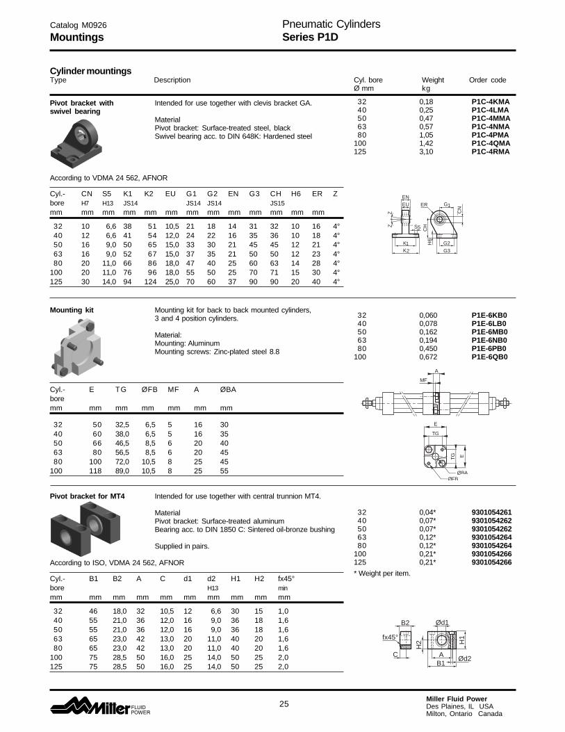
Pivot bracket with Intended for use together with clevis bracket GA.swivel bearing
MaterialPivot bracket: Surface-treated steel, blackSwivel bearing acc. to DIN 648K: Hardened steel
According to VDMA 24 562, AFNOR
Cyl.- CN S5 K1 K2 EU G1 G2 EN G3 CH H6 ER Zbore H7 H13 JS14 JS14 JS14 JS15mm mm mm mm mm mm mm mm mm mm mm mm mm
32 10 6,6 38 51 10,5 21 18 14 31 32 10 16 4°40 12 6,6 41 54 12,0 24 22 16 35 36 10 18 4°50 16 9,0 50 65 15,0 33 30 21 45 45 12 21 4°63 16 9,0 52 67 15,0 37 35 21 50 50 12 23 4°80 20 11,0 66 86 18,0 47 40 25 60 63 14 28 4°
100 20 11,0 76 96 18,0 55 50 25 70 71 15 30 4°125 30 14,0 94 124 25,0 70 60 37 90 90 20 40 4°
Mounting kit Mounting kit for back to back mounted cylinders,3 and 4 position cylinders.
Material:Mounting: AluminumMounting screws: Zinc-plated steel 8.8
Cyl.- E TG ØFB MF A ØBAboremm mm mm mm mm mm mm
32 50 32,5 6,5 5 16 3040 60 38,0 6,5 5 16 3550 66 46,5 8,5 6 20 4063 80 56,5 8,5 6 20 4580 100 72,0 10,5 8 25 45
100 118 89,0 10,5 8 25 55
Pivot bracket for MT4 Intended for use together with central trunnion MT4.
MaterialPivot bracket: Surface-treated aluminumBearing acc. to DIN 1850 C: Sintered oil-bronze bushing
Supplied in pairs.
According to ISO, VDMA 24 562, AFNOR
Cyl.- B1 B2 A C d1 d2 H1 H2 fx45°bore H13 minmm mm mm mm mm mm mm mm mm mm
32 46 18,0 32 10,5 12 6,6 30 15 1,040 55 21,0 36 12,0 16 9,0 36 18 1,650 55 21,0 36 12,0 16 9,0 36 18 1,663 65 23,0 42 13,0 20 11,0 40 20 1,680 65 23,0 42 13,0 20 11,0 40 20 1,6
100 75 28,5 50 16,0 25 14,0 50 25 2,0125 75 28,5 50 16,0 25 14,0 50 25 2,0
5
G
¯CN
CH
G2
G3
1ER
H6
KK12
S¯
EU
ZZ
EN
E
TG
ØFB
ETG
A
MF
ØBA
32 0,04* 930105426140 0,07* 930105426250 0,07* 930105426263 0,12* 930105426480 0,12* 9301054264
100 0,21* 9301054266125 0,21* 9301054266
* Weight per item.
32 0,18 P1C-4KMA40 0,25 P1C-4LMA50 0,47 P1C-4MMA63 0,57 P1C-4NMA80 1,05 P1C-4PMA
100 1,42 P1C-4QMA125 3,10 P1C-4RMA
32 0,060 P1E-6KB040 0,078 P1E-6LB050 0,162 P1E-6MB063 0,194 P1E-6NB080 0,450 P1E-6PB0
100 0,672 P1E-6QB0
C
B2
fx45°
H2
Ød1
H1
AB1
Ød2
Cylinder mountingsType Description Cyl. bore Weight Order code
Ø mm kg

Pneumatic CylindersSeries P1D
26Miller Fluid PowerDes Plaines, IL USAMilton, Ontario Canada
Catalog M0926
Mountings
Center trunnion MT4 Intended for articulated mounting of cylinder. Thisfor P1D-T mounting is only available for the tie-rod design of
P1D. The trunnion is factory-fitted in the centre of thecylinder or at an optional location specified by the XV-measure – see the order code key. Combined with pivotbracket for MT4.
Material:Trunnion: zinc plated steel
Center trunnionOrdered by letter D in position 17.See the order code key on pages 20-21.
Trunnion with optional locationOrdered by letter G in position 17 and desiredXV-measure (3-digit measure in mm) in positions 18-20.See the order code key on pages 20-21.
According to ISO MT4, VDMA 24 562, AFNOR
Cyl.- TM TL TD R UW L1 X1 XVmin X2bore h14 h14 e9mm mm mm mm mm mm mm mm mm mm
32 50 12 12 1,0 46 15 73,0 62,0 84,040 63 16 16 1,6 59 20 82,5 73,0 92,050 75 16 16 1,6 69 20 90,0 80,5 99,563 90 20 20 1,6 84 25 97,5 89,5 106,080 110 20 20 1,6 102 25 110,0 98,0 122,0
100 132 25 25 2,0 125 30 120,0 110,5 129,5125 160 25 25 2,0 155 32 145,0 132,0 158,0
XVstd = X1 + Stroke length/2XVmax = X2 + Stroke length
Flange mounted trunnion Intended for articulated mounting of cylinder. Thistrunnion can be flange mounted on the front or rear endcover of all P1D cylinders. At your choice, you canorder a complete cylinder with factory-fitted flangemounted trunnion – see the order code key on pages20 and 21. Individual trunnions have order code asshown to the right.
Material:Trunnion: zinc plated steelScrews: zinc plated steel, 8.8
Delivered complete with mounting screws forattachment to the cylinder
According to ISO MT4, VDMA 24 562, AFNOR
Cyl.- TM TL TD R UW L1 XV1 Xbore h14 h14 e9mm mm mm mm mm mm mm mm mm
32 50 12 12 1,0 46 14 19,0 127,040 63 16 16 1,6 59 19 20,5 144,550 75 16 16 1,6 69 19 27,5 152,563 90 20 20 1,6 84 24 25,0 170,080 110 20 20 1,6 102 24 34,0 186,0
100 132 25 25 2,0 155 29 36,5 203,5
XV2 = X +Stroke length
32 0,13 See order40 0,31 key on50 0,37 pages63 0,69 20 and 2180 0,89
100 1,58125 2,60
TL
UW
TM
TD
TL
R
XVstd
L1LL
XVmin
XVmax
32 0,17 P1D-4KMYF40 0,43 P1D-4LMYF50 0,55 P1D-4MMYF63 1,10 P1D-4NMYF80 1,66 P1D-4PMYF
100 3,00 P1D-4QMYF
TL
UW
TM
TD
TL
R
XV1
L1LL
XV2
L1LL
Cylinder mountingsType Description Cyl. bore Weight Order code
Ø mm kg
Pneumatic CylindersSeries P1D
27Miller Fluid PowerDes Plaines, IL USAMilton, Ontario Canada
Catalog M0926
Piston Rod Mountings
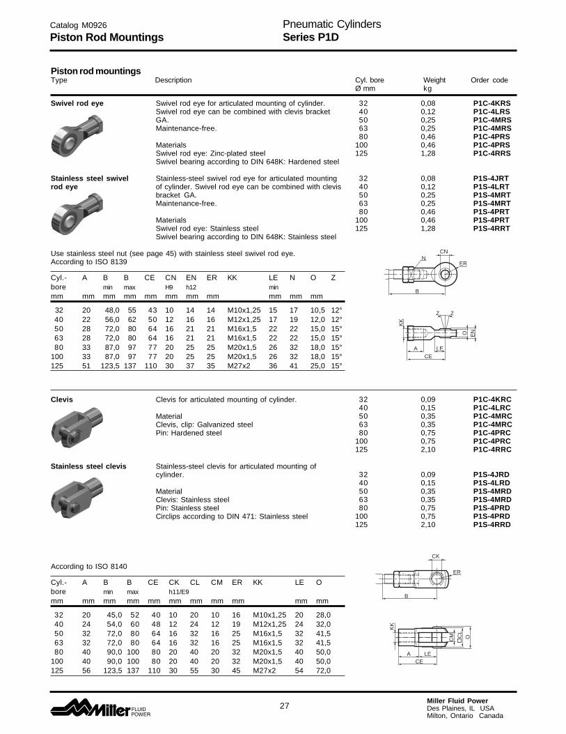
Swivel rod eye Swivel rod eye for articulated mounting of cylinder.Swivel rod eye can be combined with clevis bracketGA.Maintenance-free.
MaterialsSwivel rod eye: Zinc-plated steelSwivel bearing according to DIN 648K: Hardened steel
Stainless steel swivel Stainless-steel swivel rod eye for articulated mountingrod eye of cylinder. Swivel rod eye can be combined with clevis
bracket GA.Maintenance-free.
MaterialsSwivel rod eye: Stainless steelSwivel bearing according to DIN 648K: Stainless steel
Use stainless steel nut (see page 45) with stainless steel swivel rod eye.According to ISO 8139
Cyl.- A B B CE CN EN ER KK LE N O Zbore min max H9 h12 minmm mm mm mm mm mm mm mm mm mm mm
32 20 48,0 55 43 10 14 14 M10x1,25 15 17 10,5 12°40 22 56,0 62 50 12 16 16 M12x1,25 17 19 12,0 12°50 28 72,0 80 64 16 21 21 M16x1,5 22 22 15,0 15°63 28 72,0 80 64 16 21 21 M16x1,5 22 22 15,0 15°80 33 87,0 97 77 20 25 25 M20x1,5 26 32 18,0 15°
100 33 87,0 97 77 20 25 25 M20x1,5 26 32 18,0 15°125 51 123,5 137 110 30 37 35 M27x2 36 41 25,0 15°
Clevis Clevis for articulated mounting of cylinder.
MaterialClevis, clip: Galvanized steelPin: Hardened steel
Stainless steel clevis Stainless-steel clevis for articulated mounting ofcylinder.
MaterialClevis: Stainless steelPin: Stainless steelCirclips according to DIN 471: Stainless steel
According to ISO 8140
Cyl.- A B B CE CK CL CM ER KK LE Obore min max h11/E9mm mm mm mm mm mm mm mm mm mm mm
32 20 45,0 52 40 10 20 10 16 M10x1,25 20 28,040 24 54,0 60 48 12 24 12 19 M12x1,25 24 32,050 32 72,0 80 64 16 32 16 25 M16x1,5 32 41,563 32 72,0 80 64 16 32 16 25 M16x1,5 32 41,580 40 90,0 100 80 20 40 20 32 M20x1,5 40 50,0
100 40 90,0 100 80 20 40 20 32 M20x1,5 40 50,0125 56 123,5 137 110 30 55 30 45 M27x2 54 72,0
CK
B
ER
CELEA
CL
CM O
KK
32 0,08 P1C-4KRS40 0,12 P1C-4LRS50 0,25 P1C-4MRS63 0,25 P1C-4MRS80 0,46 P1C-4PRS
100 0,46 P1C-4PRS125 1,28 P1C-4RRS
32 0,08 P1S-4JRT40 0,12 P1S-4LRT50 0,25 P1S-4MRT63 0,25 P1S-4MRT80 0,46 P1S-4PRT
100 0,46 P1S-4PRT125 1,28 P1S-4RRT
32 0,09 P1C-4KRC40 0,15 P1C-4LRC50 0,35 P1C-4MRC63 0,35 P1C-4MRC80 0,75 P1C-4PRC
100 0,75 P1C-4PRC125 2,10 P1C-4RRC
32 0,09 P1S-4JRD40 0,15 P1S-4LRD50 0,35 P1S-4MRD63 0,35 P1S-4MRD80 0,75 P1S-4PRD
100 0,75 P1S-4PRD125 2,10 P1S-4RRD
CN
B
N
Z
ACE
LE
O
KK
EN
ER
Z
Piston rod mountingsType Description Cyl. bore Weight Order code
Ø mm kg

Pneumatic CylindersSeries P1D
28Miller Fluid PowerDes Plaines, IL USAMilton, Ontario Canada
Flexo coupling Flexo coupling for articulated mounting of piston rod.Flexo fitting is intended to take up axial angle errorswithin a range of ±4°.
MaterialFlexo coupling, nut: Zinc-plated steelSocket: Hardened steel
Supplied complete with galvanized adjustment nut.
Cyl.- B B DL EH EI EK EL EN EO EP EQ ER M Zbore min maxmm mm mm mm mm mm mm mm mm mm mm mm mm
32 36,0 43 M10x1,25 20 23 70 31 12 30 30 19 30 5,0 4°40 37,0 43 M12x1,25 23 23 67 31 12 30 30 19 30 6,0 4°50 53,0 61 M16x1,5 40 32 112 45 19 41 41 30 41 8,0 4°63 53,0 61 M16x1,5 40 32 112 45 19 41 41 30 41 8,0 4°80 57,0 67 M20x1,5 39 42 122 56 19 41 41 30 41 10,0 4°
100 57,0 67 M20x1,5 39 42 122 56 19 41 41 30 41 10,0 4°125 75,5 89 M27x2 48 48 145 60 24 55 55 32 55 13,5 4°
Nut Intended for fixed mounting of accessories to the pistonrod.Material: Zinc-plated steel
All P1D cylinders are delivred with a zinc-plated steelpistonrod nut, except P1D Clean, which is delivered with astainless steel piston rod nut instead.
Stainless steel nut Intended for fixed mounting of accessories to the pistonrod.
Material: Stainless steel A2
All P1D cylinders are delivred with a zinc-plated steelpistonrod nut, except P1D Clean, which is delivered with astainless steel piston rod nut instead.
Acid-proof nut Intended for fixed mounting of accessories to the pistonrod.
Material: Acid-proof steel A4
Cylinders with acid-proof piston rod are supplied withnut of acid-proof steel
According to DIN 439 B
Cyl.-bore A B Cmm mm mm
32 17 5,0 M10x1,2540 19 6,0 M12x1,2550 24 8,0 M16x1,563 24 8,0 M16x1,580 30 10,0 M20x1,5
100 30 10,0 M20x1,5125 41 13,5 M27x2
DL
ER
Z
M
Z
DL
EN EO EP EQ
EI
EL
B
EK
EH
M
32 0,21 P1C-4KRF40 0,22 P1C-4LRF50 0,67 P1C-4MRF63 0,67 P1C-4MRF80 0,72 P1C-4PRF
100 0,72 P1C-4PRF125 1,80 P1C-4RRF
A
C B
32 0,007 912898560140 0,010 026110991050 0,021 912898560363 0,021 912898560380 0,040 0261109911
100 0,040 0261109911125 0,100 0261109912
32 0,007 912672540440 0,010 912672540550 0,021 912672540663 0,021 912672540680 0,040 0261109921
100 0,040 0261109921125 0,100 0261109922
32 0,007 026110991940 0,010 026110992050 0,021 026110991763 0,021 026110991780 0,040 0261109916
100 0,040 0261109916125 0,100 0261109918
Piston rod mountingsType Description Cyl. bore Weight Order code
Ø mm kg
Catalog M0926
Piston Rod Mountings
Pneumatic CylindersSeries P1D
29Miller Fluid PowerDes Plaines, IL USAMilton, Ontario Canada
Catalog M0926
Accessories
32 0,02 930105432140 0,02 930105432150 0,05 930105432263 0,05 930105432280 0,09 9301054323
100 0,09 9301054323125 0,15 9301054324
32 0,02 930105433140 0,02 930105433150 0,04 930105433263 0,04 930105433280 0,07 9301054333
100 0,07 9301054333125 0,12 9301054334
32 0,01 912174220140 0,01 912174220150 0,02 912174220263 0,02 912174220280 0,02 9121742203
100 0,02 9121742203125 0,03 9121742204
AccessoriesType Description Cyl. bore Weight Order code
Ø mm kg
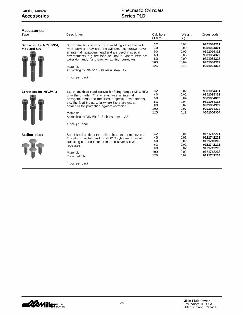
Screw set for MP2, MP4, Set of stainless steel screws for fitting clevis bracketsMS1 and GA MP2, MP4 and GA onto the cylinder. The screws have
an internal hexagonal head and are used in specialenvironments, e.g. the food industry, or where there areextra demands for protection against corrosion.
Material:According to DIN 912, Stainless steel, A2
4 pcs per pack.
Screw set for MF1/MF2 Set of stainless steel screws for fitting flanges MF1/MF2onto the cylinder. The screws have an internalhexagonal head and are used in special environments,e.g. the food industry, or where there are extrademands for protection against corrosion.
Material:According to DIN 6912, Stainless steel, A2
4 pcs per pack
Sealing plugs Set of sealing plugs to be fitted in unused end covers.The plugs can be used for all P1D cylinders to avoidcollecting dirt and fluids in the end cover screwrecesses.
Material:Polyamid PA
4 pcs per pack
Pneumatic CylindersSeries P1D
30Miller Fluid PowerDes Plaines, IL USAMilton, Ontario Canada
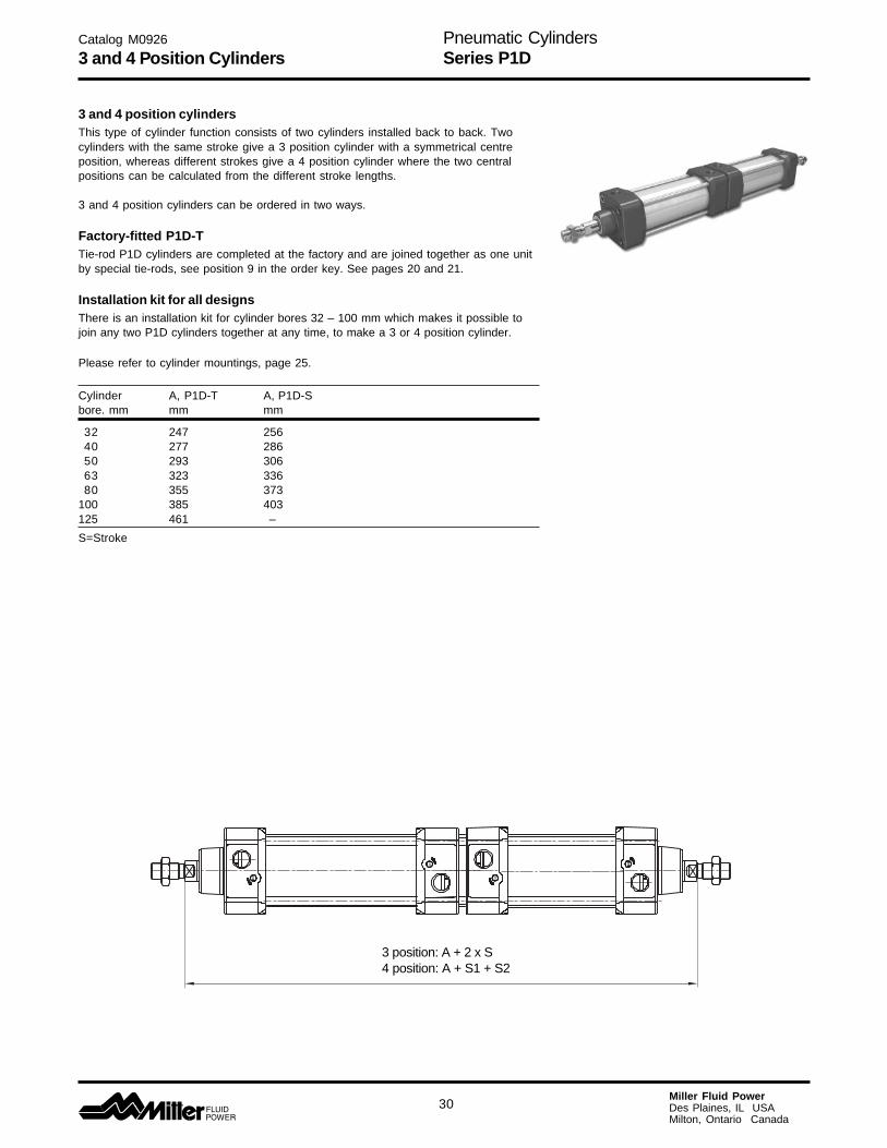
3 and 4 position cylindersThis type of cylinder function consists of two cylinders installed back to back. Twocylinders with the same stroke give a 3 position cylinder with a symmetrical centreposition, whereas different strokes give a 4 position cylinder where the two centralpositions can be calculated from the different stroke lengths.
3 and 4 position cylinders can be ordered in two ways.
Factory-fitted P1D-TTie-rod P1D cylinders are completed at the factory and are joined together as one unitby special tie-rods, see position 9 in the order key. See pages 20 and 21.
Installation kit for all designsThere is an installation kit for cylinder bores 32 – 100 mm which makes it possible tojoin any two P1D cylinders together at any time, to make a 3 or 4 position cylinder.
Please refer to cylinder mountings, page 25.
Cylinder A, P1D-T A, P1D-Sbore. mm mm mm
32 247 25640 277 28650 293 30663 323 33680 355 373
100 385 403125 461 –
S=Stroke
3 position: A + 2 x S4 position: A + S1 + S2
Catalog M0926
3 and 4 Position Cylinders
Pneumatic CylindersSeries P1D
31Miller Fluid PowerDes Plaines, IL USAMilton, Ontario Canada
StorageAt times cylinders are delivered before a customer is ready toinstall them and must be stored for a period of time. When storageis required the following procedures are recommended.
1. Store the cylinders in an indoor area which has a dry, cleanand noncorrosive atmosphere. Take care to protect thecylinder from both internal corrosion and external damage.
2. Whenever possible cylinders should be stored in a verticalposition (piston rod up). This will minimize corrosion due topossible condensation which could occur inside the cylinder.This will also minimize seal damage.
3. Port protector plugs should be left in the cylinder until the timeof installation.
4. If a cylinder is stored full of hydraulic fluid, expansion of thefluid due to temperature changes must be considered. Installinga check valve with free flow out of the cylinder is one method.
Installation1. Cleanliness is an important consideration, and Miller Fluid
Power cylinders are shipped with the ports plugged to protectthem from contaminants entering the ports. These plugs shouldnot be removed until the piping is to be installed. Before makingthe connection to the cylinder ports, piping should be thor-oughly cleaned to remove all chips or burrs which might haveresulted from threading or flaring operations.
2. Cylinders operating in an environment where air dryingmaterials are present such as fast-drying chemicals, paint, orweld splatter, or other hazardous conditions such as exces-sive heat, should have shields installed to prevent damage tothe piston rod and piston rod seals.
3. Proper alignment of the cylinder piston rod and its matingcomponent on the machine should be checked in both theextended and retracted positions. Improper alignment will resultin excessive rod gland and/or cylinder bore wear. On fixedmounting cylinders attaching the piston rod while the rod isretracted will help in achieving proper alignment.
Mounting Recommendations1. Always mount cylinders using the largest possible high tensile
alloy steel socket head screws that can fit in the cylindermounting holes and torque them to the manufacturer’srecommendations for their size.
2. Side-Mounted Cylinders – In addition to the mounting bolts,cylinders of this type should be equipped with thrust keys ordowel pins located so as to resist the major load.
3. Tie Rod Mounting – Cylinders with tie rod mountings arerecommended for applications where mounting space is limited.The standard tie rod extension is shown as BB in dimensiontables. Longer or shorter extensions can be supplied. Nutsused for this mounting style should be torqued to the samevalue as the tie rods for that bore size.
4. Flange Mount Cylinders – The controlled diameter of the rodgland extension on head end flange mount cylinders can beused as a pilot to locate the cylinders in relation to the machine.After alignment has been obtained, the flanges may be drilledfor pins or dowels to prevent shifting.
5. Trunnion Mountings – Cylinders require lubricated bearingblocks with minimum bearing clearances. Bearing blocksshould be carefully aligned and rigidly mounted so the trun-nions will not be subjected to bending moments. The rod endshould also be pivoted with the pivot pin in line and parallel toaxis of the trunnion pins.
6. Clevis Mountings – Cylinders should be pivoted at both endswith centerline of pins parallel to each other. After cylinder ismounted, be sure to check to assure that the cylinder is free toswing through its working arc without interference from othermachine parts.
Cylinder Trouble Shooting
External Leakage1. Rod seal leakage can generally be traced to worn or damaged
seals. Examine the piston rod for dents, gouges or score marks,and replace piston rod if surface is rough.
Rod seal leakage could also be traced to gland bearing wear. Ifclearance is excessive, replace rod gland and seal. Rod sealleakage can also be traced to seal deterioration. If seals aresoft or gummy or brittle, check compatibility of seal materialwith lubricant used if air cylinder, or operating fluid if hydrauliccylinder. Replace with seal material, which is compatible withthese fluids. If the seals are hard or have lost elasticity, it isusually due to exposure to temperatures in excess of 165°F.(+74°C). Shield the cylinder from the heat source to limittemperature to 350°F. (+177°C.) and replace with fluorocarbonseals.
2. Cylinder body seal leak can generally be traced to loose tierods. Torque the tie rods to manufacturer’s recommendation forthat bore size.
Excessive pressure can also result in cylinder body seal leak.Determine maximum pressure to rated limits. Replace sealsand retorque tie rods as in paragraph above. Excessivepressure can also result in cylinder body seal leak. Determineif the pressure rating of the cylinder has been exceeded. If so,bring the operating pressure down to the rating of the cylinderand have the tie rods replaced.
Pinched or extruded cylinder body seal will also result in a leak.Replace cylinder body seal and retorque as in paragraphabove.
Cylinder body seal leakage due to loss of radial squeeze whichshows up in the form of flat spots or due to wear on the O.D. orI.D. – Either of these are symptoms of normal wear due to highcycle rate or length of service. Replace seals as per paragraphabove.
Internal Leakage1. Piston seal leak (by-pass) 1 to 3 cubic inches per minute
leakage is considered normal for piston ring construction.Virtually no static leak with lipseal type seals on piston shouldbe expected. Piston seal wear is a usual cause of piston sealleakage. Replace seals as required.
2. With lipseal type piston seals excessive back pressure due toover-adjustment of speed control valves could be a directcause of rapid seal wear. Contamination in a hydraulic systemcan result in a scored cylinder bore, resulting in rapid sealwear. In either case, replace piston seals as required.
3. What appears to be piston seal leak, evidenced by the fact thatthe cylinder drifts, is not always traceable to the piston. Tomake sure, it is suggested that one side of the cylinder pistonbe pressurized and the fluid line at the opposite port bedisconnected. Observe leakage. If none is evident, seek thecause of cylinder drift in other component parts in the circuit.
Cylinder Fails to Move the Load1. Pneumatic or hydraulic pressure is too low. Check the
pressure at the cylinder to make sure it is to circuitrequirements.
2. Piston Seal Leak – Operate the valve to cycle the cylinder andobserve fluid flow at valve exhaust ports at end of cylinderstroke. Replace piston seals if flow is excessive.
3. Cylinder is undersized for the load – Replace cylinder with oneof a larger bore size.
4. Piston rod broken. Bring the operating conditions of the cylinderto the attention of our engineering department and have ourfactory repair the cylinder.
Erratic or Chatter Operation1. Excessive friction at gland or piston bearing due to load
misalignment – Correct cylinder-to-load alignment.
2. Cylinder sized too close to load requirements – Reduce load orinstall larger cylinder.
Catalog M0926
Storage/Installation/Mounting

Pneumatic CylindersSeries P1D
32Miller Fluid PowerDes Plaines, IL USAMilton, Ontario Canada
Catalog M0926
Safety Guidelines
Safety Guide for Selecting and Using Hydraulic,Pneumatic Cylinders and Their Accessories
WARNING: FAILURE OR IMPROPER SELECTION OR IMPROPER USE OF CYLINDERS AND THEIRRELATED ACCESSORIES CAN CAUSE DEATH, PERSONAL INJURY AND PROPERTY DAMAGE.
!
Before selecting or using Miller Fluid Power cylinders orrelated accessories, it is important that you read, under-stand and follow the following safety information.
User ResponsibilityDue to very wide variety of cylinder applications and cylinderoperating conditions, Miller Fluid Power does not warrant that anyparticular cylinder is suitable for any specific application. Thissafety guide does not analyze all technical parameters that mustbe considered in selecting a product. The hydraulic and pneumaticcylinders outlined in this catalog are designed to Miller FluidPower’s design guide lines and do not necessarily meet the designguide lines of other agencies such as American Bureau ofShipping, ASME Pressure Vessel Code etc. The user, through itsown analysis and testing, is solely responsible for: • Making the final selection of the cylinders and related
accessories. • Determining if the cylinders are required to meet specific design
requirements as required by the Agency(s) or industrystandards covering the design of the user’s equipment.
• Assuring that the user’s requirements are met, OSHA require-ments are met, and safety guidelines from the applicableagencies such as but not limited to ANSI are followed and thatthe use presents no health or safety hazards.
• Providing all appropriate health and safety warnings on theequipment on which the cylinders are used.
SealsPart of the process of choosing a cylinder is the selection of sealcompounds. Before making this selection read the OperatingFluids and Seals section in the Application Engineering Datasection of the current M0910 catalog, or contact our engineeringdepartment.
The application of cylinders may allow fluids such as cutting fluids,wash down fluids etc. to come in contact with the external area ofthe cylinder. These fluids may attack the piston rod wiper and orthe primary seal and must be taken into account when selectingand specifying seal compounds.
Dynamic seals will wear. The rate of wear will depend on manyoperating factors. Wear can be rapid if a cylinder is mis-aligned orif the cylinder has been improperly serviced. The user must takeseal wear into consideration in the application of cylinders.
Piston RodsPossible consequences of piston rod failure or separation of thepiston rod from the piston include, but are not limited to are:
• Piston rod and or attached load thrown off at high speed.• High velocity fluid discharge.• Piston rod extending when pressure is applied in the piston
retract mode.
Piston rods or machine members attached to the piston rod maymove suddenly and without warning as a consequence of otherconditions occurring to the machine such as, but not limited to:
• Unexpected detachment of the machine member from thepiston rod.
• Failure of the pressurized fluid delivery system (hoses, fittings,valves, pumps, compressors) which maintain cylinder position.
• Catastrophic cylinder seal failure leading to sudden loss ofpressurized fluid.
• Failure of the machine control system.
Following the recommendation of the cylinder stroke chart foundin this catalog or in the Cylinder Application Engineering Datasection of the current M0910 catalog. The suggested piston roddiameter in these charts must be followed in order to avoid pistonrod buckling.
Piston rods are not normally designed to absorb bending momentsor loads which are perpendicular to the axis of piston rod motion.These additional loads can cause the piston rod to fail. If thesetypes of additional loads are expected to be imposed on the pistonrod, their magnitude should be made known to our engineeringdepartment.
The cylinder user should always make sure that the piston rod issecurely attached to the machine member.
On occasion cylinders are ordered with double rods (a piston rodextended from both ends of the cylinder). In some cases a stop isthreaded on to one of the piston rods and used as an externalstroke adjuster. On occasions spacers are attached to themachine member connected to the piston rod and also used as astroke adjuster. In both cases the stops will create a pinch pointand the user should consider appropriate use of guards. If theseexternal stops are not perpendicular to the mating contact surface,or if debris is trapped between the contact surfaces, a bendingmoment will be placed on the piston rod, which can lead to pistonrod failure. An external stop will also negate the effect of cushion-ing and will subject the piston rod to impact loading. Those two (2)conditions can cause piston rod failure. Internal stroke adjustersare available with and without cushions. The use of external strokeadjusters should be reviewed with our engineering department.
The piston rod to piston and the stud to piston rod threadedconnections are secured with an anaerobic adhesive. Thestrength of the adhesive decreases with increasing temperature.Cylinder which can be exposed to temperatures above +250°F(+121°C) are to be ordered with a non studded piston rod and apinned piston to rod joint.
CushionsCushions should be considered for cylinder applications when thepiston velocity is expected to be over 4 inches/second.
Cylinder cushions are normally designed to absorb the energy ofa linear applied load. A rotating mass has considerably moreenergy than the same mass moving in a linear mode. Cushioningfor a rotating mass application should be review by our engineer-ing department.
Cylinder MountingsSome cylinder mounting configurations may have certainlimitations such as but not limited to minimum stroke for side orfoot mounting cylinders or pressure de-ratings for certain flangemounts. Carefully review the catalog for these types of restric-tions.
Always mount cylinders using the largest possible high tensilealloy steel socket head cap screws that can fit in the cylindermounting holes and torque them to the manufacturer’s recommen-dations for their size.
Port FittingsHydraulic cylinders applied with meter out or deceleration circuitsare subject to intensified pressure at piston rod end.
The rod end pressure is approximately equal to:
operating pressure x effective cap end area
effective rod end piston area
Contact your connector supplier for the pressure rating ofindividual connectors.
Cylinder Modifications or RepairsCylinders as shipped from the factory are not to be disassembledand or modified. If cylinders require modifications, these modifica-tions must be done at Miller Fluid Power locations or by Miller FluidPower certified facilities. It is allowed to disassemble cylinders forthe purpose of replacing seals or seal assemblies. However, thiswork must be done by strictly following all the instructionsprovided with the seal kits.

Pneumatic CylindersSeries P1D
Catalog M0926
Offer of Sale
Miller Fluid PowerDes Plaines, IL USAMilton, Ontario Canada
The items described in this document and other documents or descriptions provided by Parker Hannifin Corporation, its subsidiaries and Divisions(“Company”) and its authorized distributors, are hereby offered for sale at prices to be established by the Company, its subsidiaries and its authorizeddistributors. This offer and its acceptance by any customer (“Buyer”) shall be governed by all of the following Terms and Conditions. Buyer’s order forany such item, when communicated to the Company, its subsidiary or an authorized distributor (“Seller”) verbally or in writing, shall constituteacceptance of this offer.
1. Terms and Conditions of Sale: All descriptions, quotations, proposals,offers, acknowledgments, acceptances and sales of Seller’s products aresubject to and shall be governed exclusively by the terms and conditionsstated herein. Buyer’s acceptance of any offer to sell is limited to theseterms and conditions. Any terms or conditions in addition to, or inconsis-tent with those stated herein, proposed by Buyer in any acceptance of anoffer by Seller, are hereby objected to. No such additional, different orinconsistent terms and conditions shall become part of the contractbetween Buyer and Seller unless expressly accepted in writing by Seller.Seller’s acceptance of any offer to purchase by Buyer is expresslyconditional upon Buyer’s assent to all the terms and conditions statedherein, including any terms in addition to, or inconsistent with thosecontained in Buyer’s offer. Acceptance of Seller’s products shall in allevents constitute such assent.
2. Payment: Payment shall be made by Buyer net 30 days from the dateof delivery of the items purchased hereunder. Amounts not timely paid shallbear interest at the maximum rate permitted by law for each month orportion thereof that the Buyer is late in making payment. Any claims byBuyer for omissions or shortages in a shipment shall be waived unlessSeller receives notice thereof within 30 days after Buyer’s receipt of theshipment.3. Delivery: Unless otherwise provided on the face hereof, delivery shallbe made F.O.B. Seller’s plant. Regardless of the method of delivery,however, risk of loss shall pass to Buyer upon Seller’s delivery to a carrier.Any delivery dates shown are approximate only and Seller shall have noliability for any delays in delivery.
4. Warranty: Seller warrants that the items sold hereunder shall be freefrom defects in material or workmanship for a period of 18 months from dateof shipment from the Company. THIS WARRANTY COMPRISES THESOLE AND ENTIRE WARRANTY PERTAINING TO ITEMSPROVIDED HEREUNDER. SELLER MAKES NO OTHER WARRANTY,GUARANTEE, OR REPRESENTATION OF ANY KIND WHATSOEVER.ALL OTHER WARRANTIES, INCLUDING BUT NOT LIMITED TO,MERCHANTABILITY AND FITNESS FOR PURPOSE, WHETHEREXPRESS, IMPLIED, OR ARISING BY OPERATION OF LAW, TRADEUSAGE, OR COURSE OF DEALING ARE HEREBY DISCLAIMED.NOTWITHSTANDING THE FOREGOING, THERE ARE NO WARRAN-TIES WHATSOEVER ON ITEMS BUILT OR ACQUIRED WHOLLY ORPARTIALLY, TO BUYER’S DESIGN OR SPECIFICATIONS.5. Limitation of Remedy: SELLER’S LIABILITY ARISING FROM OR INANY WAY CONNECTED WITH THE ITEMS SOLD OR THIS CONTRACTSHALL BE LIMITED EXCLUSIVELY TO REPAIR OR REPLACEMENTOF THE ITEMS SOLD OR REFUND OF THE PURCHASE PRICE PAIDBY BUYER, AT SELLER’S SOLE OPTION. IN NO EVENT SHALLSELLER BE LIABLE FOR ANY INCIDENTAL, CONSEQUENTIAL ORSPECIAL DAMAGES OF ANY KIND OR NATURE WHATSOEVER,INCLUDING BUT NOT LIMITED TO LOST PROFITS ARISING FROM ORIN ANY WAY CONNECTED WITH THIS AGREEMENT OR ITEMS SOLDHEREUNDER, WHETHER ALLEGED TO ARISE FROM BREACH OFCONTRACT, EXPRESS OR IMPLIED WARRANTY, OR IN TORT,INCLUDING WITHOUT LIMITATION, NEGLIGENCE, FAILURE TO WARNOR STRICT LIABILITY.6. Changes, Reschedules and Cancellations: Buyer may request tomodify the designs or specifications for the items sold hereunder as wellas the quantities and delivery dates thereof, or may request to cancel allor part of this order, however, no such requested modification or cancel-lation shall become part of the contract between Buyer and Seller unlessaccepted by Seller in a written amendment to this Agreement. Acceptanceof any such requested modification or cancellation shall be at Seller’sdiscretion, and shall be upon such terms and conditions as Seller mayrequire.
7. Special Tooling: A tooling charge may be imposed for any specialtooling, including without limitations, dies, fixtures, molds and patterns,acquired to manufacture items sold pursuant to this contract. Such specialtooling shall be and remain Seller’s property notwithstanding payment ofany charges by Buyer. In no event will Buyer acquire any interest inapparatus belonging to Seller which is utilized in the manufacture of theitems sold hereunder, even if such apparatus has been specially convertedor adapted for such manufacture and notwithstanding any charges paid by
Buyer. Unless otherwise agreed, Seller shall have the right to alter, discardor otherwise dispose of any special tooling or other property in its solediscretion at any time.8. Buyer’s Property: Any designs, tools, patterns, materials, drawings,confidential information or equipment furnished by Buyer, or any otheritems which become Buyer’s property, may be considered obsolete andmay be destroyed by Seller after two (2) consecutive years have elapsedwithout Buyer placing an order for the items which are manufactured usingsuch property. Seller shall not be responsible for any loss or damage tosuch property while it is in Seller’s possession or control.
9. Taxes: Unless otherwise indicated on the face hereof, all prices andcharges are exclusive of excise, sales, use, property, occupational or liketaxes which may be imposed by any taxing authority upon the manufac-ture, sale or delivery of the items sold hereunder. If any such taxes mustbe paid by Seller or if Seller is liable for the collection of such tax, theamount thereof shall be in addition to the amounts for the items sold. Buyeragrees to pay all such taxes or to reimburse Seller therefore upon receiptof its invoice. If Buyer claims exemption from any sales, use or other taximposed by any taxing authority, Buyer shall save Seller harmless fromand against any such tax, together with any interest or penalties thereonwhich may be assessed if the items are held to be taxable.
10. Indemnity For Infringement of Intellectual Property Rights: Sellershall have no liability for infringement of any patents, trademarks, copy-rights, trade dress, trade secrets or similar rights except as provided in thisPart 10. Seller will defend and indemnify Buyer against allegations ofinfringement of U.S. patents, U.S. trademarks, copyrights, trade dress andtrade secrets (hereinafter “Intellectual Property Rights”). Seller will defendat its expense and will pay the cost of any settlement or damages awardedin an action brought against Buyer based on an allegation that an item soldpursuant to this contract infringes the Intellectual Property Rights of a thirdparty. Seller’s obligation to defend and indemnify Buyer is contingent onBuyer notifying Seller within ten (10) days after Buyer becomes aware ofsuch allegations of infringement, and Seller having sole control over thedefense of any allegations or actions including all negotiations for settlementor compromise. If an item sold hereunder is subject to a claim that it infringesthe Intellectual Property Rights of a third party, Seller may, at its soleexpense and option, procure for Buyer the right to continue using said item,replace or modify said item so as to make it noninfringing, or offer to acceptreturn of said item and return the purchase price less a reasonable allowancefor depreciation. Notwithstanding the foregoing, Seller shall have no liabilityfor claims of infringement based on information provided by Buyer, ordirected to items delivered hereunder for which the designs are specified inwhole or part by Buyer, or infringements resulting from the modification,combination or use in a system of any item sold hereunder. The foregoingprovisions of this Part 10 shall constitute Seller’s sole and exclusive liabilityand Buyer’s sole and exclusive remedy for infringement of IntellectualProperty Rights.If a claim is based on information provided by Buyer or if the design for anitem delivered hereunder is specified in whole or in part by Buyer, Buyershall defend and indemnify Seller for all costs, expenses or judgementsresulting from any claim that such item infringes any patent, trademark,copyright, trade dress, trade secret or any similar right.
11. Force Majeure: Seller does not assume the risk of and shall not beliable for delay or failure to perform any of Seller’s obligations by reasonof circumstances beyond the reasonable control of Seller (hereinafter“Events of Force Majeure”). Events of Force Majeure shall include withoutlimitation, accidents, acts of God, strikes or labor disputes, acts, laws, rulesor regulations of any government or government agency, fires, floods,delays or failures in delivery of carriers or suppliers, shortages of materialsand any other cause beyond Seller’s control.
12. Entire Agreement/Governing Law: The terms and conditions setforth herein, together with any amendments, modifications and anydifferent terms or conditions expressly accepted by Seller in writing, shallconstitute the entire Agreement concerning the items sold, and there areno oral or other representations or agreements which pertain thereto. ThisAgreement shall be governed in all respects by the law of the State of Ohio.No actions arising out of sale of the items sold hereunder or this Agreementmay be brought by either party more than two (2) years after the cause ofaction accrues.
Offer of Sale
©2003 Parker Hannifin Corporation Printed in U.S.A.January, 2004
All specifications and information subject tochange without notice or prior obligation.
Catalog M092601/04
Miller Fluid Power500 South Wolf RoadDes Plaines, IL 60016 USA(847) 298-2400(800) 892-1008—FAXWeb site: www.millerfluidpower.com
Miller Fluid Power8485 Parkhill Dr.Milton, Ontario,Canada L9T 5E9(905) 693-3000(905) 876-1958—FAX