Embed Size (px)
Citation preview
ISO 6022 HYDRAULIC CYLINDERSISO 6022 HYDRAULIEK CILINDERS
01-
D50/36-200-SUM-CF(b)
06.12.20111:2.5
JGB
678157-691-
SFG
06.12.2011
A
TITLE:
DATE:
DATE:
DWG.NR.: FORMAT:
PAGE.:
CHECK.:SCALE:
DRAWN.:
CHANGED:
NEN-ISO 2768-1-m
LENGTH TOLERANCES:
NEN-ISO 1101
SURFACE ROUGHNESS:
NEN-ISO 2768-2
FORM- AND PLACE TOLERANCES:
THIS DRAWING IS PROPERTY OF ABS VEENDAM AND SHALL NOT BE COPIED, USED OR LEND TO THIRD PARTIES WITHOUT PERMISSION OF ABS VEENDAM.
A3
De Zwaaikom 3
ABS Veendam
www.abshydro.nl
Unique into Hydraulics!
Projection: Am.
9641 KV Veendam
Unless otherwise stated:Units:
Roughness:Tolerance:Chamfer:
mm.3.2
0,10,5x45°
WWW.ABSHYDRO.NLWWW.REMB.BE
3
ISO 6022 HYDRAULIC CYLINDERSISO 6022 HYDRAULIEK CILINDERS
ABS Cilinders B.V. in Veendam (NL) and REM-B Hydraulics NV in Beerse (BE) hereby jointly present the ISO6022 cylinder. Because of this cooperation in production and sales of the ISO6022 ABS and REM-B take a leading position in terms of quality, delivery times and prices. For Russia and the Netherlands ABS will be the contact and for France and Belgium REM-B will handle this.The ISO6022 cylinder is characterized by welding-free assembly that means of screw+ nutconnestions where the seals and materials of only the highest quality are used. This specially for the industry develo-ped cylinder can be equipped with proximity switches and / or position measuring system. Also a bushing drain, SAE oilconnectors, adjustable cushioning and various mounting elements are standard options.In this catalog you can use the standard sizes which are available. If required our sales department can advise you about the (rod) choices supported by a digital drawing you can directly implement into your project.
ABS Cilinders B.V. in Veendam (NL) en REM-B Hydraulics NV in Beerse (BE) presenteren hierbij samen de ISO6022 cilinder. Door deze samenwerking op het gebied van productie en verkoop van de ISO6022 nemen ABS en REM-B een toonaangevende positie in op het gebied van kwaliteit, levertijd en prijs. Voor Rusland en Nederland is ABS het aanspreekpunt en voor Frankrijk en Belgie gaat REM-B dit verzorgen.De ISO6022 kenmerkt zich door lasvrije montage door middel van schroef+boutverbinding waarbij de afdichtingen en materialen van alleen de allerhoogste kwaliteit worden toegepast. Deze speciaal voor de industrie ontwikkelde cilinders kunnen worden uitgevoerd met inductieve benaderingsschakelaars en / of een wegmeetsysteem. Tevens behoren een lekolie aansluiting, SAE aansluitingen, instelbare dempingen en diverse bevestigingen tot de standaard opties.In deze catalogus kunt u de “standaard” maatvoeringen vinden. Indien gewenst adviseren onze verkopers u graag bij de juiste (stang) keuze ondersteund door een digitale tekening op schaal die u gelijk in uw project kunt implementeren
Hoogachtend,
ABS Cilinders BV REM-B Hydraulics BV De Zwaaikom 3 Rouwbergskens 5NL9641 KV VEENDAM B2340 BEERSE(The Netherlands) (Belgium)
www.abshydro.nl [email protected] [email protected].: +31 (0) 598 62 25 44 Tel.: +32 14 62 28 60
Verkoop voor NL en Rusland Verkoop voor Belgie en Frankrijk
4
ISO 6022 HYDRAULIC CYLINDERSISO 6022 HYDRAULIEK CILINDERS
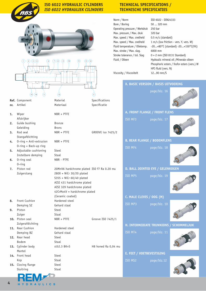
X. BASIC VERSION / BASIS UITVOERING
page/blz. 16
A. FRONT FLANGE / FRONT FLENS
ISO MF3 page/blz. 17
B. REAR FLANGE / BODEMFLENS
ISO MF4 page/blz. 18
D. BALL JOINTED EYE / GELENKOGEN
ISO MP5 page/blz. 19
C. MALE CLEVIS / OOG (M)
ISO MP3 page/blz. 10
H. INTERMEDIATE TRUNNIONS / SCHOMMELJUK
ISO MT4 page/blz. 11
E. FEET / VOETBEVESTIGING
ISO MS2 page/blz.12
Component Material Specifications
Artikel Materiaal Specificatie
Wiper NBR + PTFE
Afstrijker
Guide bushing Bronze
Geleiding Brons
Rod seal NBR + PTFE GROOVE iso 7425/2
Stangafdichting
O-ring + Anti-extrusion NBR + PTFE
O-ring + Back-up ring
Adjustable cushioning Steel
Instelbare demping Staal
O-ring seal NBR - PTFE
O-ring
Piston rod 20MnV6 hardchrome plated ISO f7 Ra 0.20 mu
Zuigerstang 280X + NiCr 30/20 plated
S355 + NiCr 60/40 plated
AISI 431 hardchrome plated
AISI 329 hardchrome plated
42CrMo4V = hardchrome plated
(Ceramic coated)
Front Cushion Hardened steel
Demping SZ Gehard staal
Piston Steel
Zuiger Staal
Piston seal NBR + PTFE Groove ISO 7425/1
Zuigerafdichting
Rear Cushion Hardened steel
Demping BZ Gehard staal
Rear head Steel
Bodem Staal
Cylinder body st52.3 BK+S H8 honed Ra 0,04 mu
Mantel
Front head Steel
Kop Staal
Closing flange Steel
Sluitring Staal
Norm / Norm ISO 6022 - DIN24333Bore / Boring 50 ... 320 mmOperating pressure / Werkdruk 250 barMax. pressure / Max. druk 320 barMax. speed / Max. snelheid 0.5 m/s (standard)Max. speed / Max. snelheid 1 m/s (low friction - vers. Y, vers. W) Fluid temperature / Olietemp. -20...+80°C (standard) -20...+150°C(Vit)Max. stroke / Max. slag. 6000 mm Stroke tolerance / tol. Slag 0 + 2 mm (ISO 8131 Standard)Fluid / Olieen Hydraulic mineral oil /Minerale olieen Phosphoric esters / fosfor esters (vers.) W HFC-fluid (vers. N)Viscosity / Viscositeit 12...90 mm/S
TECHNICAL SPECIFICATIONS / TECHNISCHE SPECIFICATIES
ISO 6022 HYDRAULIC CYLINDERSISO 6022 HYDRAULIEK CILINDERS
Ref. nr.
1.
2.
3.
4.
5.
6.
7.
8.
9.
10.
11.
12.
13.
14.
15.
5
ISO 6022 HYDRAULIC CYLINDERSISO 6022 HYDRAULIEK CILINDERS
Norm / Norm ISO 6022 - DIN24333Bore / Boring 50 ... 320 mmOperating pressure / Werkdruk 250 barMax. pressure / Max. druk 320 barMax. speed / Max. snelheid 0.5 m/s (standard)Max. speed / Max. snelheid 1 m/s (low friction - vers. Y, vers. W) Fluid temperature / Olietemp. -20...+80°C (standard) -20...+150°C(Vit)Max. stroke / Max. slag. 6000 mm Stroke tolerance / tol. Slag 0 + 2 mm (ISO 8131 Standard)Fluid / Olieen Hydraulic mineral oil /Minerale olieen Phosphoric esters / fosfor esters (vers.) W HFC-fluid (vers. N)Viscosity / Viscositeit 12...90 mm/S
TECHNICAL SPECIFICATIONS / TECHNISCHE SPECIFICATIES
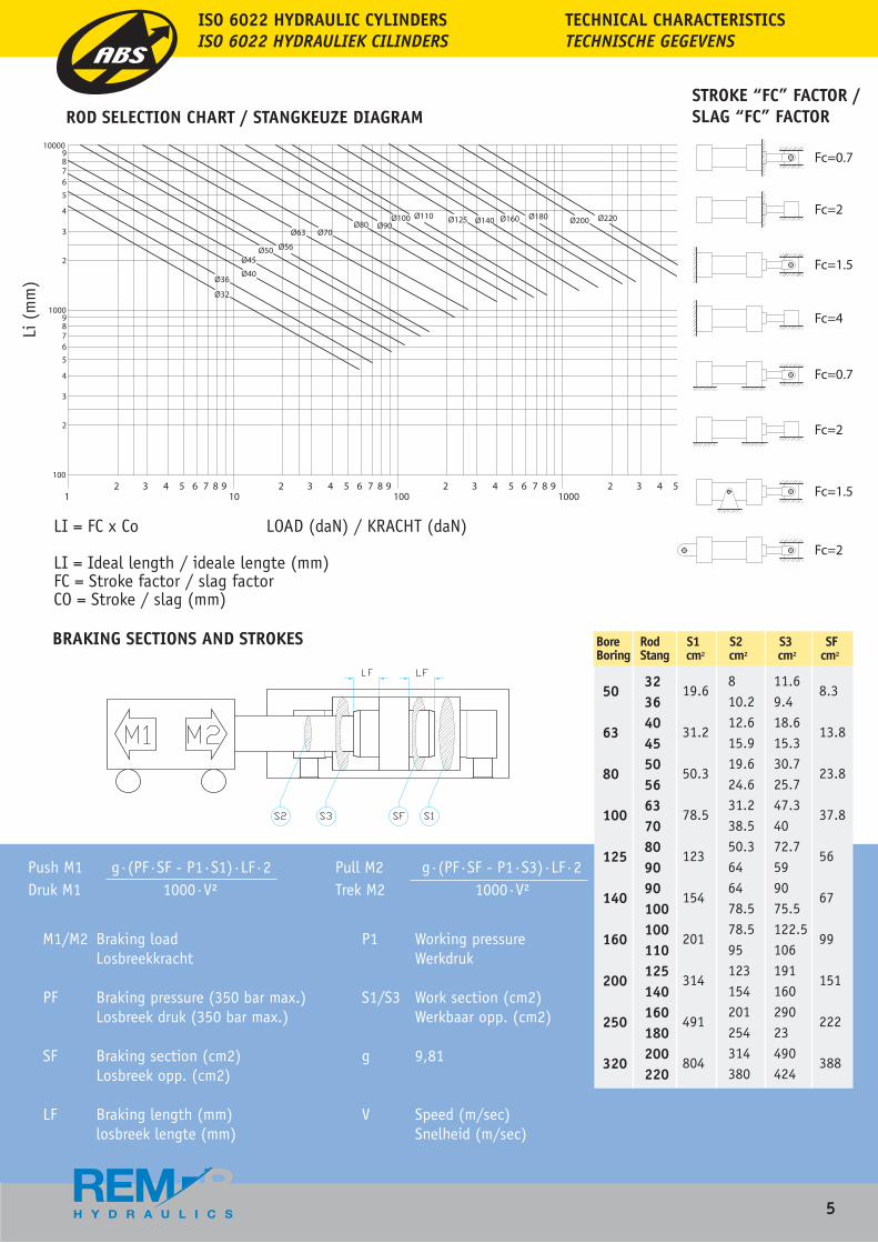
M1/M2 Braking load P1 Working pressure Losbreekkracht Werkdruk PF Braking pressure (350 bar max.) S1/S3 Work section (cm2) Losbreek druk (350 bar max.) Werkbaar opp. (cm2)
SF Braking section (cm2) g 9,81 Losbreek opp. (cm2)
LF Braking length (mm) V Speed (m/sec) losbreek lengte (mm) Snelheid (m/sec)
BRAKING SECTIONS AND STROKES
ROD SELECTION CHART / STANGKEUZE DIAGRAMSTROKE “FC” FACTOR / SLAG “FC” FACTOR
ISO 6022 HYDRAULIC CYLINDERSISO 6022 HYDRAULIEK CILINDERS
TECHNICAL CHARACTERISTICSTECHNISCHE GEGEVENS
LI = FC x Co LOAD (daN) / KRACHT (daN)
LI = Ideal length / ideale lengte (mm)FC = Stroke factor / slag factor CO = Stroke / slag (mm)
Push M1 g·(PF·SF - P1·S1)·LF·2 Druk M1 1000·V²
Pull M2 g·(PF·SF - P1·S3)·LF·2 Trek M2 1000·V²
50
63
80
100
125
140
160
200
250
320
3236404550566370809090100100110125140160180200220
19.6
31.2
50.3
78.5
123
154
201
314
491
804
810.212.615.919.624.631.238.550.3646478.578.595123154201254314380
11.69.418.615.330.725.747.34072.7599075.5122.510619116029023490424
8.3
13.8
23.8
37.8
56
67
99
151
222
388
Bore Rod S1 S2 S3 SFBoring Stang cm² cm² cm² cm²
Li (
mm
)
6
ISO 6022 HYDRAULIC CYLINDERSISO 6022 HYDRAULIEK CILINDERS
Boring Stang
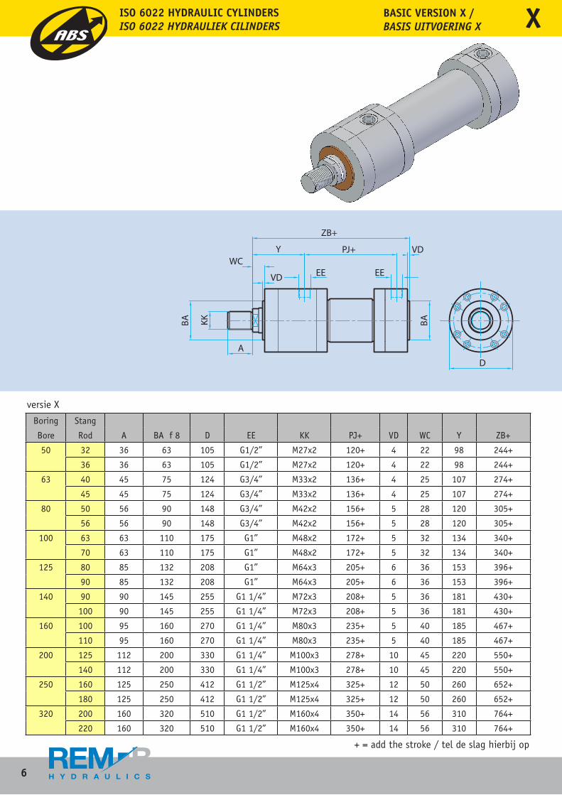
Bore Rod A BA f 8 D EE KK PJ+ VD WC Y ZB+
50 32 36 63 105 G1/2” M27x2 120+ 4 22 98 244+
36 36 63 105 G1/2” M27x2 120+ 4 22 98 244+
63 40 45 75 124 G3/4” M33x2 136+ 4 25 107 274+
45 45 75 124 G3/4” M33x2 136+ 4 25 107 274+
80 50 56 90 148 G3/4” M42x2 156+ 5 28 120 305+
56 56 90 148 G3/4” M42x2 156+ 5 28 120 305+
100 63 63 110 175 G1” M48x2 172+ 5 32 134 340+
70 63 110 175 G1” M48x2 172+ 5 32 134 340+
125 80 85 132 208 G1” M64x3 205+ 6 36 153 396+
90 85 132 208 G1” M64x3 205+ 6 36 153 396+
140 90 90 145 255 G1 1/4” M72x3 208+ 5 36 181 430+
100 90 145 255 G1 1/4” M72x3 208+ 5 36 181 430+
160 100 95 160 270 G1 1/4” M80x3 235+ 5 40 185 467+
110 95 160 270 G1 1/4” M80x3 235+ 5 40 185 467+
200 125 112 200 330 G1 1/4” M100x3 278+ 10 45 220 550+
140 112 200 330 G1 1/4” M100x3 278+ 10 45 220 550+
250 160 125 250 412 G1 1/2” M125x4 325+ 12 50 260 652+
180 125 250 412 G1 1/2” M125x4 325+ 12 50 260 652+
320 200 160 320 510 G1 1/2” M160x4 350+ 14 56 310 764+
220 160 320 510 G1 1/2” M160x4 350+ 14 56 310 764+
+ = add the stroke / tel de slag hierbij op
BASIC VERSION X /BASIS UITVOERING X X
versie X
7
ISO 6022 HYDRAULIC CYLINDERSISO 6022 HYDRAULIEK CILINDERS
Boring Stang
Bore Rod A BA f 8 D EE KK PJ+ VD WC Y ZB+
50 32 36 63 105 G1/2” M27x2 120+ 4 22 98 244+
36 36 63 105 G1/2” M27x2 120+ 4 22 98 244+
63 40 45 75 124 G3/4” M33x2 136+ 4 25 107 274+
45 45 75 124 G3/4” M33x2 136+ 4 25 107 274+
80 50 56 90 148 G3/4” M42x2 156+ 5 28 120 305+
56 56 90 148 G3/4” M42x2 156+ 5 28 120 305+
100 63 63 110 175 G1” M48x2 172+ 5 32 134 340+
70 63 110 175 G1” M48x2 172+ 5 32 134 340+
125 80 85 132 208 G1” M64x3 205+ 6 36 153 396+
90 85 132 208 G1” M64x3 205+ 6 36 153 396+
140 90 90 145 255 G1 1/4” M72x3 208+ 5 36 181 430+
100 90 145 255 G1 1/4” M72x3 208+ 5 36 181 430+
160 100 95 160 270 G1 1/4” M80x3 235+ 5 40 185 467+
110 95 160 270 G1 1/4” M80x3 235+ 5 40 185 467+
200 125 112 200 330 G1 1/4” M100x3 278+ 10 45 220 550+
140 112 200 330 G1 1/4” M100x3 278+ 10 45 220 550+
250 160 125 250 412 G1 1/2” M125x4 325+ 12 50 260 652+
180 125 250 412 G1 1/2” M125x4 325+ 12 50 260 652+
320 200 160 320 510 G1 1/2” M160x4 350+ 14 56 310 764+
220 160 320 510 G1 1/2” M160x4 350+ 14 56 310 764+
+ = add the stroke / tel de slag hierbij op
BASIC VERSION X /BASIS UITVOERING X
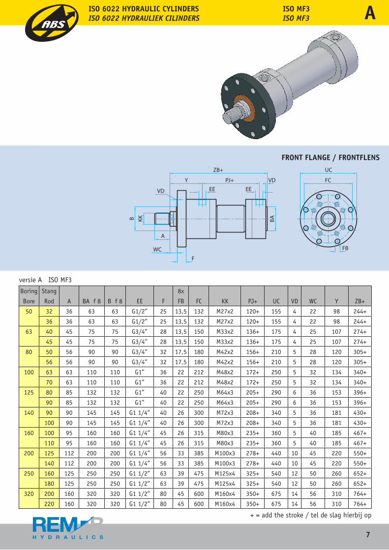
Boring Stang 8x
Bore Rod A BA f 8 B f 8 EE F FB FC KK PJ+ UC VD WC Y ZB+
50 32 36 63 63 G1/2” 25 13,5 132 M27x2 120+ 155 4 22 98 244+
36 36 63 63 G1/2” 25 13,5 132 M27x2 120+ 155 4 22 98 244+
63 40 45 75 75 G3/4” 28 13,5 150 M33x2 136+ 175 4 25 107 274+
45 45 75 75 G3/4” 28 13,5 150 M33x2 136+ 175 4 25 107 274+
80 50 56 90 90 G3/4” 32 17,5 180 M42x2 156+ 210 5 28 120 305+
56 56 90 90 G3/4” 32 17,5 180 M42x2 156+ 210 5 28 120 305+
100 63 63 110 110 G1” 36 22 212 M48x2 172+ 250 5 32 134 340+
70 63 110 110 G1” 36 22 212 M48x2 172+ 250 5 32 134 340+
125 80 85 132 132 G1” 40 22 250 M64x3 205+ 290 6 36 153 396+
90 85 132 132 G1” 40 22 250 M64x3 205+ 290 6 36 153 396+
140 90 90 145 145 G1 1/4” 40 26 300 M72x3 208+ 340 5 36 181 430+
100 90 145 145 G1 1/4” 40 26 300 M72x3 208+ 340 5 36 181 430+
160 100 95 160 160 G1 1/4” 45 26 315 M80x3 235+ 360 5 40 185 467+
110 95 160 160 G1 1/4” 45 26 315 M80x3 235+ 360 5 40 185 467+
200 125 112 200 200 G1 1/4” 56 33 385 M100x3 278+ 440 10 45 220 550+
140 112 200 200 G1 1/4” 56 33 385 M100x3 278+ 440 10 45 220 550+
250 160 125 250 250 G1 1/2” 63 39 475 M125x4 325+ 540 12 50 260 652+
180 125 250 250 G1 1/2” 63 39 475 M125x4 325+ 540 12 50 260 652+
320 200 160 320 320 G1 1/2” 80 45 600 M160x4 350+ 675 14 56 310 764+
220 160 320 320 G1 1/2” 80 45 600 M160x4 350+ 675 14 56 310 764+
+ = add the stroke / tel de slag hierbij op
versie A ISO MF3
ISO MF3ISO MF3
FRONT FLANGE / FRONTFLENS
X A
8
ISO 6022 HYDRAULIC CYLINDERSISO 6022 HYDRAULIEK CILINDERS
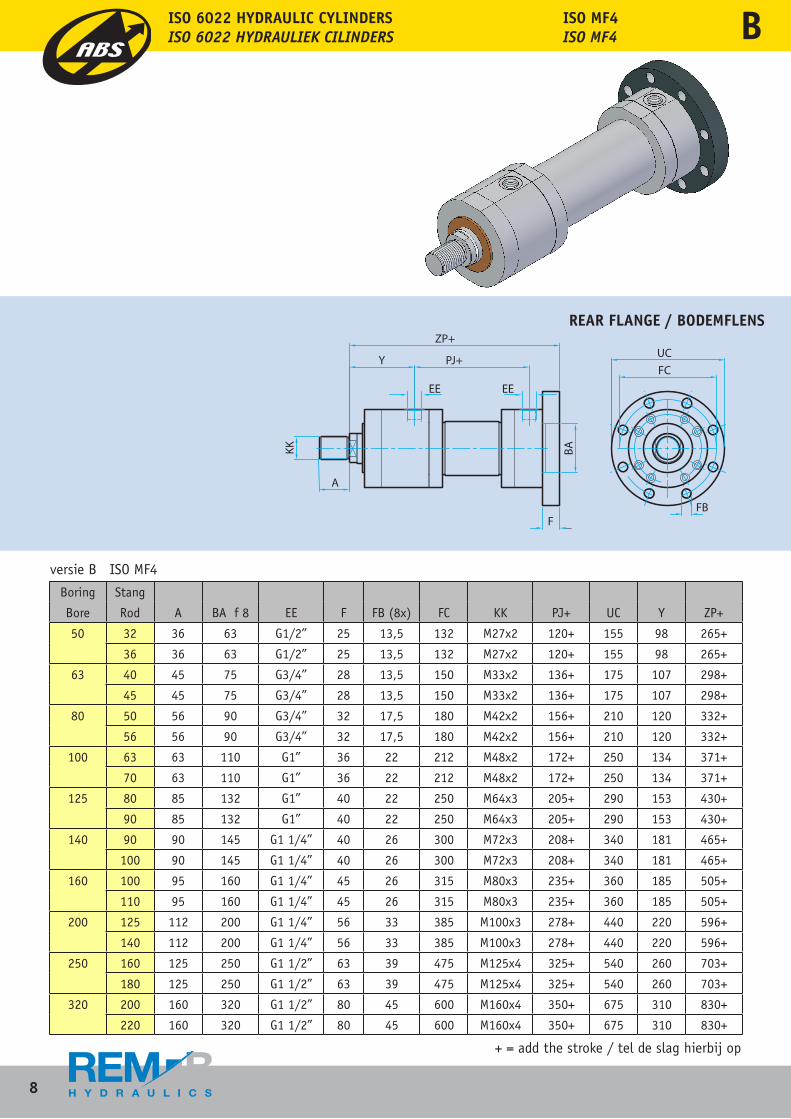
Boring Stang
Bore Rod A BA f 8 EE F FB (8x) FC KK PJ+ UC Y ZP+
50 32 36 63 G1/2” 25 13,5 132 M27x2 120+ 155 98 265+
36 36 63 G1/2” 25 13,5 132 M27x2 120+ 155 98 265+
63 40 45 75 G3/4” 28 13,5 150 M33x2 136+ 175 107 298+
45 45 75 G3/4” 28 13,5 150 M33x2 136+ 175 107 298+
80 50 56 90 G3/4” 32 17,5 180 M42x2 156+ 210 120 332+
56 56 90 G3/4” 32 17,5 180 M42x2 156+ 210 120 332+
100 63 63 110 G1” 36 22 212 M48x2 172+ 250 134 371+
70 63 110 G1” 36 22 212 M48x2 172+ 250 134 371+
125 80 85 132 G1” 40 22 250 M64x3 205+ 290 153 430+
90 85 132 G1” 40 22 250 M64x3 205+ 290 153 430+
140 90 90 145 G1 1/4” 40 26 300 M72x3 208+ 340 181 465+
100 90 145 G1 1/4” 40 26 300 M72x3 208+ 340 181 465+
160 100 95 160 G1 1/4” 45 26 315 M80x3 235+ 360 185 505+
110 95 160 G1 1/4” 45 26 315 M80x3 235+ 360 185 505+
200 125 112 200 G1 1/4” 56 33 385 M100x3 278+ 440 220 596+
140 112 200 G1 1/4” 56 33 385 M100x3 278+ 440 220 596+
250 160 125 250 G1 1/2” 63 39 475 M125x4 325+ 540 260 703+
180 125 250 G1 1/2” 63 39 475 M125x4 325+ 540 260 703+
320 200 160 320 G1 1/2” 80 45 600 M160x4 350+ 675 310 830+
220 160 320 G1 1/2” 80 45 600 M160x4 350+ 675 310 830+
+ = add the stroke / tel de slag hierbij op
versie B ISO MF4
ISO MF4ISO MF4
REAR FLANGE / BODEMFLENS
B
9
ISO 6022 HYDRAULIC CYLINDERSISO 6022 HYDRAULIEK CILINDERS
+ = add the stroke / tel de slag hierbij op
REAR FLANGE / BODEMFLENS
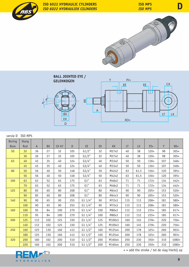
Boring Stang
Bore Rod A BX CX H7 D EE EX KK LT LX PJ+ Y XO+
50 32 36 27 32 105 G1/2” 32 M27x2 40 38 120+ 98 305+
36 36 27 32 105 G1/2” 32 M27x2 40 38 120+ 98 305+
63 40 45 35 40 124 G3/4” 40 M33x2 50 50 136+ 107 348+
45 45 35 40 124 G3/4” 40 M33x2 50 50 136+ 107 348+
80 50 56 40 50 148 G3/4” 50 M42x2 63 61,5 156+ 120 395+
56 56 40 50 148 G3/4” 50 M42x2 63 61,5 156+ 120 395+
100 63 63 52 63 175 G1” 63 M48x2 71 71 172+ 134 442+
70 63 52 63 175 G1” 63 M48x2 71 71 172+ 134 442+
125 80 85 60 80 208 G1” 80 M64x3 90 90 205+ 153 520+
90 85 60 80 208 G1” 80 M64x3 90 90 205+ 153 520+
140 90 90 65 90 255 G1 1/4” 90 M72x3 115 113 208+ 181 580+
100 90 65 90 255 G1 1/4” 90 M72x3 115 113 208+ 181 580+
160 100 95 84 100 270 G1 1/4” 100 M80x3 112 112 235+ 185 617+
110 95 84 100 270 G1 1/4” 100 M80x3 112 112 235+ 185 617+
200 125 112 102 125 330 G1 1/4” 125 M100x3 160 145 278+ 220 756+
140 112 102 125 330 G1 1/4” 125 M100x3 160 145 278+ 220 756+
250 160 125 130 160 412 G1 1/2” 160 M125x4 200 178 325+ 260 903+
180 125 130 160 412 G1 1/2” 160 M125x4 200 178 325+ 260 903+
320 200 160 162 200 510 G1 1/2” 200 M160x4 250 230 350+ 310 1080+
220 160 162 200 510 G1 1/2” 200 M160x4 250 230 350+ 310 1080+
+ = add the stroke / tel de slag hierbij op
versie D ISO MP5
ISO MP5ISO MP5
BALL JOINTED EYE / GELENKOGEN
B D
10
ISO 6022 HYDRAULIC CYLINDERSISO 6022 HYDRAULIEK CILINDERS
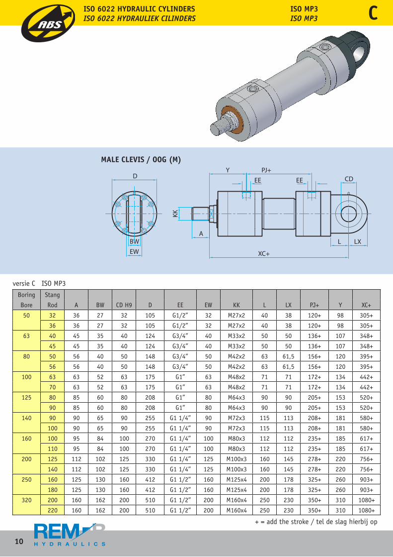
Boring Stang
Bore Rod A BW CD H9 D EE EW KK L LX PJ+ Y XC+
50 32 36 27 32 105 G1/2” 32 M27x2 40 38 120+ 98 305+
36 36 27 32 105 G1/2” 32 M27x2 40 38 120+ 98 305+
63 40 45 35 40 124 G3/4” 40 M33x2 50 50 136+ 107 348+
45 45 35 40 124 G3/4” 40 M33x2 50 50 136+ 107 348+
80 50 56 40 50 148 G3/4” 50 M42x2 63 61,5 156+ 120 395+
56 56 40 50 148 G3/4” 50 M42x2 63 61,5 156+ 120 395+
100 63 63 52 63 175 G1” 63 M48x2 71 71 172+ 134 442+
70 63 52 63 175 G1” 63 M48x2 71 71 172+ 134 442+
125 80 85 60 80 208 G1” 80 M64x3 90 90 205+ 153 520+
90 85 60 80 208 G1” 80 M64x3 90 90 205+ 153 520+
140 90 90 65 90 255 G1 1/4” 90 M72x3 115 113 208+ 181 580+
100 90 65 90 255 G1 1/4” 90 M72x3 115 113 208+ 181 580+
160 100 95 84 100 270 G1 1/4” 100 M80x3 112 112 235+ 185 617+
110 95 84 100 270 G1 1/4” 100 M80x3 112 112 235+ 185 617+
200 125 112 102 125 330 G1 1/4” 125 M100x3 160 145 278+ 220 756+
140 112 102 125 330 G1 1/4” 125 M100x3 160 145 278+ 220 756+
250 160 125 130 160 412 G1 1/2” 160 M125x4 200 178 325+ 260 903+
180 125 130 160 412 G1 1/2” 160 M125x4 200 178 325+ 260 903+
320 200 160 162 200 510 G1 1/2” 200 M160x4 250 230 350+ 310 1080+
220 160 162 200 510 G1 1/2” 200 M160x4 250 230 350+ 310 1080+
+ = add the stroke / tel de slag hierbij op
versie C ISO MP3
ISO MP3ISO MP3
MALE CLEVIS / OOG (M)
C
11
ISO 6022 HYDRAULIC CYLINDERSISO 6022 HYDRAULIEK CILINDERS
Boring Stang
Bore Rod A BW CD H9 D EE EW KK L LX PJ+ Y XC+
50 32 36 27 32 105 G1/2” 32 M27x2 40 38 120+ 98 305+
36 36 27 32 105 G1/2” 32 M27x2 40 38 120+ 98 305+
63 40 45 35 40 124 G3/4” 40 M33x2 50 50 136+ 107 348+
45 45 35 40 124 G3/4” 40 M33x2 50 50 136+ 107 348+
80 50 56 40 50 148 G3/4” 50 M42x2 63 61,5 156+ 120 395+
56 56 40 50 148 G3/4” 50 M42x2 63 61,5 156+ 120 395+
100 63 63 52 63 175 G1” 63 M48x2 71 71 172+ 134 442+
70 63 52 63 175 G1” 63 M48x2 71 71 172+ 134 442+
125 80 85 60 80 208 G1” 80 M64x3 90 90 205+ 153 520+
90 85 60 80 208 G1” 80 M64x3 90 90 205+ 153 520+
140 90 90 65 90 255 G1 1/4” 90 M72x3 115 113 208+ 181 580+
100 90 65 90 255 G1 1/4” 90 M72x3 115 113 208+ 181 580+
160 100 95 84 100 270 G1 1/4” 100 M80x3 112 112 235+ 185 617+
110 95 84 100 270 G1 1/4” 100 M80x3 112 112 235+ 185 617+
200 125 112 102 125 330 G1 1/4” 125 M100x3 160 145 278+ 220 756+
140 112 102 125 330 G1 1/4” 125 M100x3 160 145 278+ 220 756+
250 160 125 130 160 412 G1 1/2” 160 M125x4 200 178 325+ 260 903+
180 125 130 160 412 G1 1/2” 160 M125x4 200 178 325+ 260 903+
320 200 160 162 200 510 G1 1/2” 200 M160x4 250 230 350+ 310 1080+
220 160 162 200 510 G1 1/2” 200 M160x4 250 230 350+ 310 1080+
Boring Stang
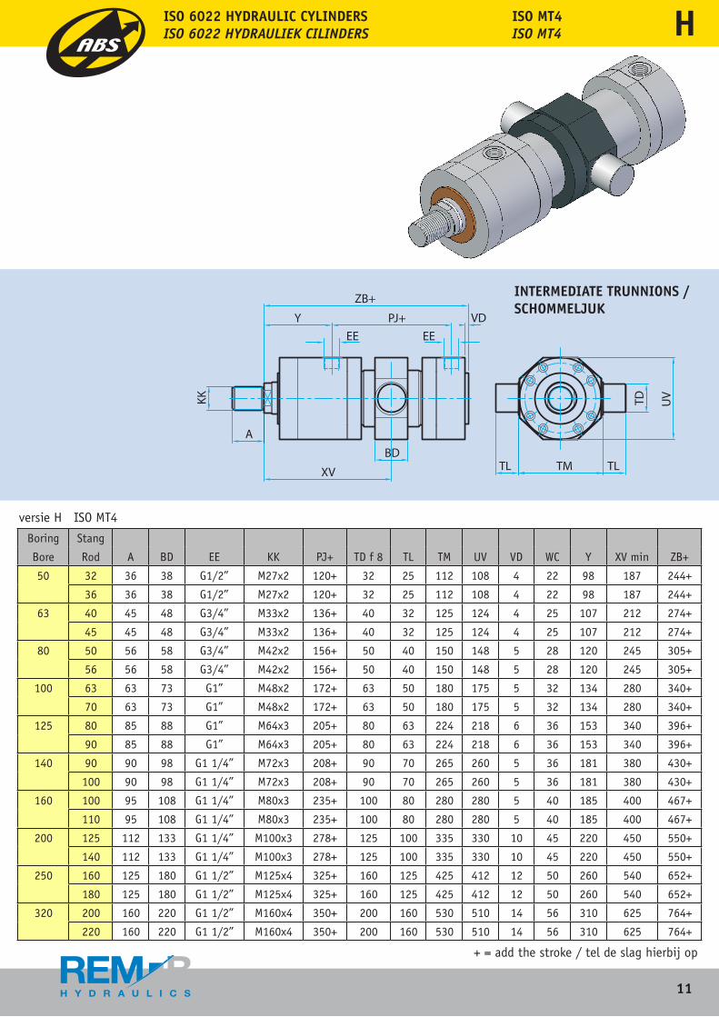
Bore Rod A BD EE KK PJ+ TD f 8 TL TM UV VD WC Y XV min ZB+
50 32 36 38 G1/2” M27x2 120+ 32 25 112 108 4 22 98 187 244+
36 36 38 G1/2” M27x2 120+ 32 25 112 108 4 22 98 187 244+
63 40 45 48 G3/4” M33x2 136+ 40 32 125 124 4 25 107 212 274+
45 45 48 G3/4” M33x2 136+ 40 32 125 124 4 25 107 212 274+
80 50 56 58 G3/4” M42x2 156+ 50 40 150 148 5 28 120 245 305+
56 56 58 G3/4” M42x2 156+ 50 40 150 148 5 28 120 245 305+
100 63 63 73 G1” M48x2 172+ 63 50 180 175 5 32 134 280 340+
70 63 73 G1” M48x2 172+ 63 50 180 175 5 32 134 280 340+
125 80 85 88 G1” M64x3 205+ 80 63 224 218 6 36 153 340 396+
90 85 88 G1” M64x3 205+ 80 63 224 218 6 36 153 340 396+
140 90 90 98 G1 1/4” M72x3 208+ 90 70 265 260 5 36 181 380 430+
100 90 98 G1 1/4” M72x3 208+ 90 70 265 260 5 36 181 380 430+
160 100 95 108 G1 1/4” M80x3 235+ 100 80 280 280 5 40 185 400 467+
110 95 108 G1 1/4” M80x3 235+ 100 80 280 280 5 40 185 400 467+
200 125 112 133 G1 1/4” M100x3 278+ 125 100 335 330 10 45 220 450 550+
140 112 133 G1 1/4” M100x3 278+ 125 100 335 330 10 45 220 450 550+
250 160 125 180 G1 1/2” M125x4 325+ 160 125 425 412 12 50 260 540 652+
180 125 180 G1 1/2” M125x4 325+ 160 125 425 412 12 50 260 540 652+
320 200 160 220 G1 1/2” M160x4 350+ 200 160 530 510 14 56 310 625 764+
220 160 220 G1 1/2” M160x4 350+ 200 160 530 510 14 56 310 625 764+
+ = add the stroke / tel de slag hierbij op
versie H ISO MT4
ISO MT4ISO MT4
INTERMEDIATE TRUNNIONS /SCHOMMELJUK
C H
12
ISO 6022 HYDRAULIC CYLINDERSISO 6022 HYDRAULIEK CILINDERS
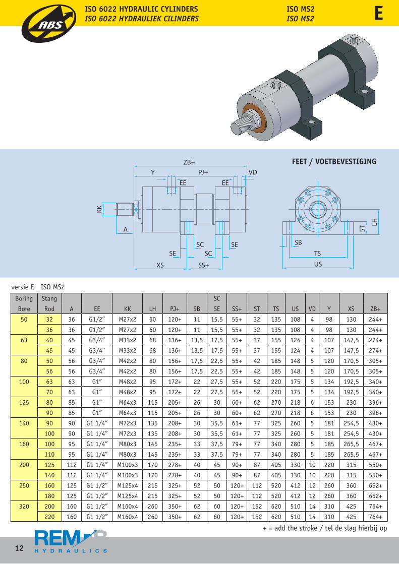
Boring Stang SC
Bore Rod A EE KK LH PJ+ SB SE SS+ ST TS US VD Y XS ZB+
50 32 36 G1/2” M27x2 60 120+ 11 15,5 55+ 32 135 108 4 98 130 244+
36 36 G1/2” M27x2 60 120+ 11 15,5 55+ 32 135 108 4 98 130 244+
63 40 45 G3/4” M33x2 68 136+ 13,5 17,5 55+ 37 155 124 4 107 147,5 274+
45 45 G3/4” M33x2 68 136+ 13,5 17,5 55+ 37 155 124 4 107 147,5 274+
80 50 56 G3/4” M42x2 80 156+ 17,5 22,5 55+ 42 185 148 5 120 170,5 305+
56 56 G3/4” M42x2 80 156+ 17,5 22,5 55+ 42 185 148 5 120 170,5 305+
100 63 63 G1” M48x2 95 172+ 22 27,5 55+ 52 220 175 5 134 192,5 340+
70 63 G1” M48x2 95 172+ 22 27,5 55+ 52 220 175 5 134 192,5 340+
125 80 85 G1” M64x3 115 205+ 26 30 60+ 62 270 218 6 153 230 396+
90 85 G1” M64x3 115 205+ 26 30 60+ 62 270 218 6 153 230 396+
140 90 90 G1 1/4” M72x3 135 208+ 30 35,5 61+ 77 325 260 5 181 254,5 430+
100 90 G1 1/4” M72x3 135 208+ 30 35,5 61+ 77 325 260 5 181 254,5 430+
160 100 95 G1 1/4” M80x3 145 235+ 33 37,5 79+ 77 340 280 5 185 265,5 467+
110 95 G1 1/4” M80x3 145 235+ 33 37,5 79+ 77 340 280 5 185 265,5 467+
200 125 112 G1 1/4” M100x3 170 278+ 40 45 90+ 87 405 330 10 220 315 550+
140 112 G1 1/4” M100x3 170 278+ 40 45 90+ 87 405 330 10 220 315 550+
250 160 125 G1 1/2” M125x4 215 325+ 52 50 120+ 112 520 412 12 260 360 652+
180 125 G1 1/2” M125x4 215 325+ 52 50 120+ 112 520 412 12 260 360 652+
320 200 160 G1 1/2” M160x4 260 350+ 62 60 120+ 152 620 510 14 310 425 764+
220 160 G1 1/2” M160x4 260 350+ 62 60 120+ 152 620 510 14 310 425 764+
+ = add the stroke / tel de slag hierbij op
versie E ISO MS2
ISO MS2ISO MS2
FEET / VOETBEVESTIGING
E
13
ISO 6022 HYDRAULIC CYLINDERSISO 6022 HYDRAULIEK CILINDERS
Boring Stang SC
Bore Rod A EE KK LH PJ+ SB SE SS+ ST TS US VD Y XS ZB+
50 32 36 G1/2” M27x2 60 120+ 11 15,5 55+ 32 135 108 4 98 130 244+
36 36 G1/2” M27x2 60 120+ 11 15,5 55+ 32 135 108 4 98 130 244+
63 40 45 G3/4” M33x2 68 136+ 13,5 17,5 55+ 37 155 124 4 107 147,5 274+
45 45 G3/4” M33x2 68 136+ 13,5 17,5 55+ 37 155 124 4 107 147,5 274+
80 50 56 G3/4” M42x2 80 156+ 17,5 22,5 55+ 42 185 148 5 120 170,5 305+
56 56 G3/4” M42x2 80 156+ 17,5 22,5 55+ 42 185 148 5 120 170,5 305+
100 63 63 G1” M48x2 95 172+ 22 27,5 55+ 52 220 175 5 134 192,5 340+
70 63 G1” M48x2 95 172+ 22 27,5 55+ 52 220 175 5 134 192,5 340+
125 80 85 G1” M64x3 115 205+ 26 30 60+ 62 270 218 6 153 230 396+
90 85 G1” M64x3 115 205+ 26 30 60+ 62 270 218 6 153 230 396+
140 90 90 G1 1/4” M72x3 135 208+ 30 35,5 61+ 77 325 260 5 181 254,5 430+
100 90 G1 1/4” M72x3 135 208+ 30 35,5 61+ 77 325 260 5 181 254,5 430+
160 100 95 G1 1/4” M80x3 145 235+ 33 37,5 79+ 77 340 280 5 185 265,5 467+
110 95 G1 1/4” M80x3 145 235+ 33 37,5 79+ 77 340 280 5 185 265,5 467+
200 125 112 G1 1/4” M100x3 170 278+ 40 45 90+ 87 405 330 10 220 315 550+
140 112 G1 1/4” M100x3 170 278+ 40 45 90+ 87 405 330 10 220 315 550+
250 160 125 G1 1/2” M125x4 215 325+ 52 50 120+ 112 520 412 12 260 360 652+
180 125 G1 1/2” M125x4 215 325+ 52 50 120+ 112 520 412 12 260 360 652+
320 200 160 G1 1/2” M160x4 260 350+ 62 60 120+ 152 620 510 14 310 425 764+
220 160 G1 1/2” M160x4 260 350+ 62 60 120+ 152 620 510 14 310 425 764+
FEET / VOETBEVESTIGING
BUSHING DRAIN / LEKOLIE AANSLUITING
PROXIMITY SWITCHES / BENADERINGSSCHAKELAARS
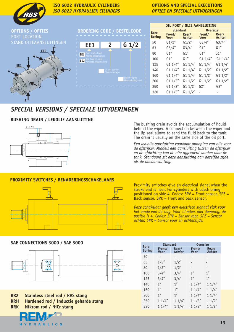
50 G1/2” G1/2” G3/4” G3/4”63 G3/4” G3/4” G1” G1”80 G1” G1” G1” G1”100 G1” G1” G1 1/4” G1 1/4”125 G1 1/4” G1 1/4” G1 1/4” G1 1/4”140 G1 1/4” G1 1/4” G1 1/2” G1 1/2”160 G1 1/4” G1 1/4” G1 1/2” G1 1/2”200 G1 1/2” G1 1/2” G1 1/2” G1 1/2”250 G1 1/2” G1 1/2” G2” G2”320 G1 1/2” G1 1/2” - -
OIL PORT / OLIE AANSLUITING
BoreBoring
Standard OversizeFront/Voor
Front/Voor
Rear/Achter
Rear/Achter
SAE CONNECTIONS 3000 / SAE 3000
OPTIONS / OPTIES ORDERING CODE / BESTELCODEPORT LOCATIONSTAND OLIEAANSLUITINGEN
OPTIONS AND SPECIAL EXECUTIONSOPTIES EN SPECIALE UITVOERINGEN
EE1 2 G 1/2EE1
EE2
Front head oil portVoorste olieaansluiting Rear head oil pointAchterste olieaansluiting
Oil port positionOlieaansluitingen
Size of oil portOlieaansluiting maat
SPECIAL VERSIONS / SPECIALE UITVOERINGEN
The bushing drain avoids the acculmulation of liquid behind the wiper. A connection between the wiper and the lip seal allows to send the fluid back to the tank. The drain is usually on the same side of the oil port.
Een lek-olie-aansluiting voorkomt ophoping van olie voor de afstrijker. Middels een aansluiting tussen de afstrijker en de afdichting kan de olie afgevoerd worden naar de tank. Standaard zit deze aansluiting aan dezelfde zijde als de olieaansluiting.
Proximity smitches give an electrical signal when the stroke end is near. For cylinders with cuschioning, positioned on side 4. Codes: SPV = Front sensor, SPZ = Back sensor, SPK = Front and back sensor.
Deze schakelaar geeft een elektrisch signaal vlak voor het einde van de slag. Voor cilinders met demping, de positie is 4. Codes: SPV = Sensor voor, SPZ = Sensor achter, SPK = Sensor voor en achterzijde.
50 - - - -63 1/2” 1/2” - -80 1/2” 1/2” - -100 3/4” 3/4” 1” 1”125 3/4” 3/4” 1” 1”140 1” 1” 1 1/4” 1 1/4”160 1” 1” 1 1/4” 1 1/4”200 1” 1” 1 1/4” 1 1/4”250 1 1/4” 1 1/4” 1 1/2” 1 1/2”320 1 1/4” 1 1/4” 1 1/2” 1 1/2”
BoreBoring
Standard OversizeFront/Voor
Front/Voor
Rear/Achter
Rear/Achter
RRX Stainless steel rod / RVS stang RRH Hardened rod / Inductie geharde stangRRK Nikrom rod / NiCr stang
E
EE1
EE2
4
3
2 3
2
1
1 4
14
ISO 6022 HYDRAULIC CYLINDERSISO 6022 HYDRAULIEK CILINDERS
50
63
80
100
125
140
160
200
250
320
3236404550566370809090
100100110125140160180200220
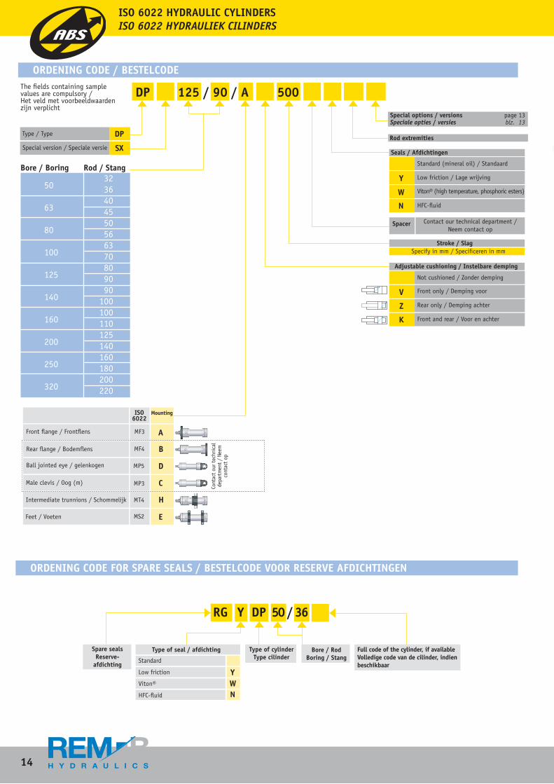
DP 125 / 90 / A 500 The fields containing sample values are compulsory / Het veld met voorbeeldwaarden zijn verplicht
Bore / Boring Rod / Stang
Special options / versions page 13Speciale opties / versies blz. 13 Rod extremities
Seals / Afdichtingen
Y
W
N
Standard (mineral oil) / Standaard
Low friction / Lage wrijving
Viton® (high temperature, phosphoric esters)
HFC-fluid
Spacer Contact our technical department /Neem contact op
Stroke / Slag Specify in mm / Specificeren in mm
Adjustable cushioning / Instelbare demping
V
Z
K
Not cushioned / Zonder demping
Front only / Demping voor
Rear only / Demping achter
Front and rear / Voor en achter
DP
SXSpecial version / Speciale versie
Type / Type
ISO 6022 HYDRAULIC CYLINDERSISO 6022 HYDRAULIEK CILINDERS
ORDENING CODE / BESTELCODE
ORDENING CODE FOR SPARE SEALS / BESTELCODE VOOR RESERVE AFDICHTINGEN
RG Y DP 50 / 36
Spare seals Reserve-
afdichting
Type of seal / afdichting Type of cylinderType cilinder
Bore / RodBoring / Stang
Full code of the cylinder, if availableVolledige code van de cilinder, indien beschikbaar
Standard
Low friction
Viton®
HFC-fluid
YWN
Front flange / Frontflens
Rear flange / Bodemflens
Ball jointed eye / gelenkogen
Male clevis / Oog (m)
Intermediate trunnions / Schommelijk
Feet / Voeten
ISO 6022
Mounting
A
B
C
D
H
E
MF3
MF4
MP5
MP3
MT4
MS2
Cont
act
our t
echn
ical
de
part
men
t /
Neem
co
ntac
t op
15
ISO 6022 HYDRAULIC CYLINDERSISO 6022 HYDRAULIEK CILINDERS
Viton® (high temperature, phosphoric esters)
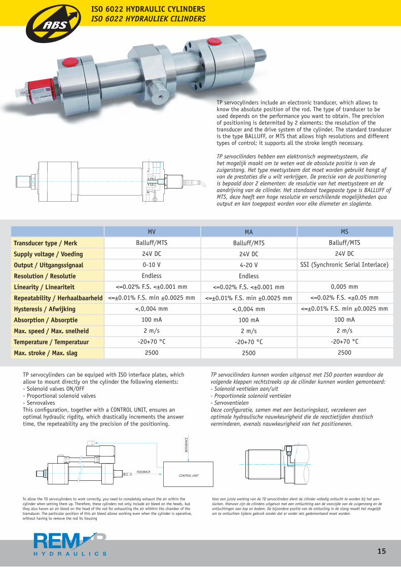
TP servocylinders include an electronic tranducer, which allows to know the absolute position of the rod. The type of tranducer to be used depends on the performance you want to obtain. The precision of positioning is determited by 2 elements: the resolution of the transducer and the drive system of the cylinder. The standard tranducer is the type BALLUFF, or MTS that allows high resolutions and different types of control; it supports all the stroke length necessary.
TP servocilinders hebben een elektronisch wegmeetsysteem, die het mogelijk maakt om te weten wat de absolute positie is van de zuigerstang. Het type meetsysteem dat moet worden gebruikt hangt af van de prestaties die u wilt verkrijgen. De precisie van de positionering is bepaald door 2 elementen: de resolutie van het meetsysteem en de aandrijving van de cilinder. Het standaard toegepaste type is BALLUFF of MTS, deze heeft een hoge resolutie en verschillende mogelijkheden qua output en kan toegepast worden voor elke diameter en slaglente.
TP servocylinders can be equiped with ISO interface plates, which allow to mount directly on the cylinder the following elements: - Solenoid valves ON/OFF- Proportional solenoid valves- ServovalvesThis configuration, together with a CONTROL UNIT, ensures an optimal hydraulic rigdity, which drastically increments the answer time, the repeteability any the precision of the positioning.
Transducer type / Merk
Supply voltage / Voeding
Output / Uitgangssignaal
Resolution / Resolutie
Linearity / Lineariteit
Repeatability / Herhaalbaarheid
Hysteresis / Afwijking
Absorption / Absorptie
Max. speed / Max. snelheid
Temperature / Temperatuur
Max. stroke / Max. slag
MV
Balluff/MTS
24V DC
0-10 V
Endless
<=0.02% F.S. <±0.001 mm
<=±0.01% F.S. min ±0.0025 mm
<,0,004 mm
100 mA
2 m/s
-20+70 °C
2500
MA
Balluff/MTS
24V DC
4-20 V
Endless
<=0.02% F.S. <±0.001 mm
<=±0.01% F.S. min ±0.0025 mm
<,0,004 mm
100 mA
2 m/s
-20+70 °C
2500
MS
Balluff/MTS
24V DC
SSI (Synchronic Serial Interlace)
0,005 mm
<=0.02% F.S. <±0.05 mm
<=±0.01% F.S. min ±0.0025 mm
100 mA
2 m/s
-20+70 °C
2500
Voor een juiste werking van de TD servocilinders dient de cilinder volledig ontlucht te worden bij het aan-sluiten. Hiervoor zijn de cilinders uitgerust met een ontluchting aan de voorzijde van de zuigerstang en de ontluchtingen aan kop en bodem. De bijzondere positie van de ontlucting in de stang maakt het mogelijk om te ontluchten tijdens gebruik zonder dat er verder iets gedemonteerd moet worden.
TP servocilinders kunnen worden uitgerust met ISO poorten waardoor de volgende kleppen rechtstreeks op de cilinder kunnen worden gemonteerd:- Solenoid ventielen aan/uit- Proportionele solenoid ventielen- ServoventielenDeze configuratie, samen met een besturingskast, verzekeren een optimale hydraulische nauwkeurigheid die de reactietijden drastisch verminderen, evenals nauwkeurigheid van het positioneren.
To allow the TD servocylinders to work correctly, you need to completely exhaust the air within the cylinder when setting them up. Therefore, these cylinders not only include air bleed on the heads, but they also haven an air bleed on the head of the rod for exhausting the air withhin the chamber of the transducer. The particular position of this air bleed allows working even when the cylinder is operative, without having to remove the rod its housing
16
ISO 6022 HYDRAULIC CYLINDERSISO 6022 HYDRAULIEK CILINDERS
ISO 6022 HYDRAULIC CYLINDERSISO 6022 HYDRAULIEK CILINDERS
50
63
80
100
125
140
160
200
250
320
3236404550566370809090
100100110125140160180200220
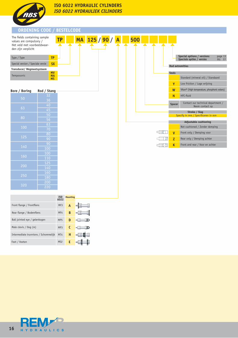
The fields containing sample values are compulsory /Het veld met voorbeeldwaar-den zijn verplicht
Bore / Boring Rod / Stang
Y
W
N
Special options / versions page 13 Speciale opties / versies blz. 13
Rod extremities
Seals
Standard (mineral oil) / Standaard
Low friction / Lage wrijving
Viton® (high temperature, phosphoric esters)
HFC-fluid
Spacer Contact our technical department / Neem contact op
Stroke / SlagSpecify in mm / Specificeren in mm
Adjustable cushioning
V
Z
K
Not cushioned / Zonder demping
Front only / Demping voor
Rear only / Demping achter
Front and rear / Voor en achter
TP
SXSpecial version / Speciale versie
Type / Type
Front flange / Frontflens
Rear flange / Bodemflens
Ball jointed eye / gelenkogen
Male clevis / Oog (m)
Intermediate trunnions / Schommelijk
Feet / Voeten
ISO 6022
Mounting
A
B
C
D
H
E
MF3
MF4
MP5
MP3
MT4
MS2
ORDENING CODE / BESTELCODE
TP MA 125 / 90 / A 500
Temposonic MVMAMS
Transducer/ Wegmeetsysteem
Special options / versions page 13 Speciale opties / versies blz. 13
ISO 6022 HYDRAULIC CYLINDERSISO 6022 HYDRAULIEK CILINDERS
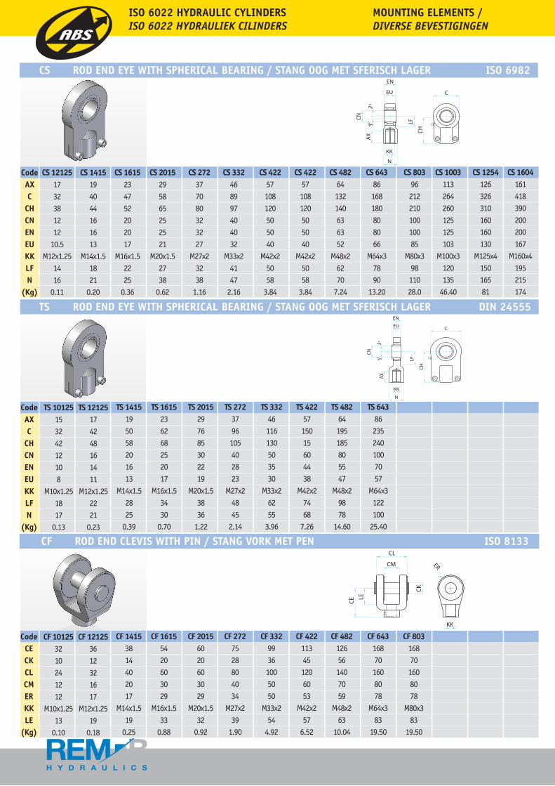
CS ROD END EYE WITH SPHERICAL BEARING / STANG OOG MET SFERISCH LAGER ISO 6982
TS ROD END EYE WITH SPHERICAL BEARING / STANG OOG MET SFERISCH LAGER DIN 24555
CodeAXC
CHCNENEUKKLFN
(Kg)
CS 121251732381212
10.5M12x1.25
1416
0.11
CS 1415194044161613
M14x1.51821
0.20
CS 1615234752202017
M16x1.52225
0.36
CS 2015295865252521
M20x1.52738
0.62
CS 272377080323227
M27x23238
1.16
CS 332468997404032
M33x24147
2.16
CS 42257108120505040
M42x25058
3.84
CS 42257108120505040
M42x25058
3.84
CS 48264132140636352
M48x26270
7.24
CS 64386168180808066
M64x37890
13.20
CS 8039621221010010085
M80x39811028.0
CS 1003113264260125125103
M100x3120135
46.40
CS 1254126326310160160130
M125x415016581
CS 1604161418390200200167
M160x4195215174
CF 101253210241212
M10x1.2513
0.10
CF 121253612321617
M12x1.2519
0.18
CF 14153814402017
M14x1.519
0.25
CF 16155420603029
M16x1.533
0.88
CF 20156020603029
M20x1.532
0.92
CF 2727528804034
M27x239
1.90
CF 33299361005050
M33x254
4.92
CF 422113451206053
M42x257
6.52
CF 482126561407059
M48x263
10.04
CF 643168701608078
M64x383
19.50
CodeCECKCLCMERKKLE
(Kg)
CF 803168701608078
M80x383
19.50
CF ROD END CLEVIS WITH PIN / STANG VORK MET PEN ISO 8133
CodeAXC
CHCNENEUKKLFN
(Kg)
TS 1012515324212108
M10x1.251817
0.13
TS 12125174248161411
M12x1.252221
0.23
TS 1415195058201613
M14x1.52825
0.39
TS 1615236268252017
M16x1.53430
0.70
TS 2015297685302219
M20x1.53836
1.22
TS 2723796105402823
M27x24845
2.14
TS 33246116130503530
M33x26255
3.96
TS 4225715015604438
M42x27468
7.26
TS 48264195185805547
M48x29878
14.60
TS 643862352401007057
M64x3122100
25.40
ISO 6022 HYDRAULIC CYLINDERSISO 6022 HYDRAULIEK CILINDERS
MOUNTING ELEMENTS / DIVERSE BEVESTIGINGEN
EN
EU
AX
N
KK
LF3°
CN
3°
ISO 6022 HYDRAULIC CYLINDERSISO 6022 HYDRAULIEK CILINDERS
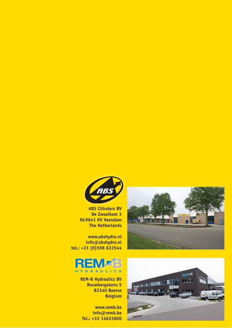
ABS Cilinders BVDe Zwaaikom 3
NL9641 KV VeendamThe Netherlands
tel.: +31 (0)598 622544
REM-B Hydraulics BVRouwbergskens 5
B2340 Beerse Belgium
Tel.: +32 14622860