Embed Size (px)
Citation preview
INTERNATIONAL STANDARD
IS0 2867
Fifth edition 1994-08-I 5
Earth-moving machinery - Access systems
Engins de terrassement - Moyens d’acchs
Reference number IS0 2867:1994(E)
IS0 2867:1994(E)
Foreword
IS0 (the International Organization for Standardization) is a worldwide federation of national standards bodies (IS0 member bodies). The work of preparing International Standards is normally carried out through IS0 technical committees. Each member body interested in a subject for which a technical committee has been established has the right to be represented on that committee. International organizations, governmental and non-governmental, in liaison with ISO, also take part in the work. IS0 collaborates closely with the International Electrotechnical Commission (IEC) on all matters of electrotechnical standardization.
Draft International Standards adopted by the technical committees are circulated to the member bodies for voting. Publication as an International Standard requires approval by at least 75 % of the member bodies casting a vote.
Internationa! Standard IS0 2867 was prepared by Technical Committee lSO/TC 127, Earth-moving machinery, Subcommittee SC 2, Safety re- quirements and human factors.
This fifth edition cancels and replaces the fourth edition (IS0 2867:1989), which has been technically revised.
Annex A of this International Standard is for information only.
0 IS0 1994 All rights reserved. Unless otherwise specified, no part of this publication may be reproduced or utilized in any form or by any means, electronic or mechanical, including photocopying and microfilm, without permission in writing from the publisher.
International Organization for Standardization Case Postale 56 l CH-1211 Geneve 20 l Switzerland
Printed in Switzerland
ii
INTERNATIONAL STANDARD 0 Iso IS0 2887:1994(E)
Earth-moving machinery - Access systems
1 Scope
This International Standard specifies criteria for ac- cess systems - steps, ladders, walkways, platforms, grab rails (handrails), grab handles, guardrails and en- closure entrance and exit openings - as they relate to aiding the operator and servicemen in performing their functions on the machinery.
It applies to access systems to the operator’s station and to service points on earth-moving machinery as defined in IS0 6165 while the machinery is parked in accordance with manufacturer’s instructions.
2 Normative references
The following standards contain provisions which, through reference in this text, constitute provisions of this International Standard. At the time of publica- tion, the editions indicated were valid. All standards are subject to revision, and parties to agreements based on this International Standard are encouraged to investigate the possibility of applying the most re- cent editions of the standards indicated below. Members of IEC and IS0 maintain registers of cur- rently valid International Standards.
IS0 3411 :1982, Earth-moving machinery - Human physical dimensions of operators and minimum oper- a tor space envelope.
IS0 6165:1987, Earth-moving machinery - Basic types - Vocabulary.
3.1 access system: System provided on a machine for entrance to and exit from an operator, inspection or maintenance platform from and to the ground.
The primary access system is the access system normally used, while the alternative access system is the access route used during anticipated emergency situations when the primary access system cannot be used.
3.2 basic dimension: Dimensional value which takes into account human factors criteria. The actual value may vary within the specified range.
3.3 enclosure opening: Opening leading to or from an access system and large enough for a person to pass through.
3.3.1 primary opening: Opening normally used for access.
3.3.2 alternative opening: Opening for use during emergencies when the primary opening is not usable.
3.3.3 service opening: Opening for use during maintenance, service or inspection.
3.4 guardrail: Device along the open sides of walk- ways or platforms to protect a person from falling.
3.5 handrail and handhold: Parts of an access system that may be grasped by the hand as an aid to body support and balance.
3.51 handrail: Device which permits hand move- ment to a different location without removing the hand from the device.
3.5.2 handhold: Device for single hand placement. 3 Definitions
For the purposes of this International Standard, the following definitions apply.
3.6 slip-resistant surface: Access system surface having qualities which improve the traction obtained by the foot.
1
IS0 2887:1994(E) 6 IS0 **
3.7 ladder
3.7.1 inclined ladder: Ladder whose angle of incli- nation from the horizontal is greater than 50” but not more than 75”.
3.7.2 vertical ladder: Ladder whose angle of incli- nation from the horizontal is greater than 75”, but not more than 90”.
3.7.3 ladder fall-limiting device: Any device which minimizes or limits the length of fall from a ladder system.
3.8 stairway: Access system or part of an access system inclined from the horizontal at an angle greater than 20” but not more than 50” and consisting of four or more steps.
3.9 step: Device for placement of one or both feet, either as part of a ladder or stairway, or installed (placed) individually.
3.10 rung: Device on which one or both feet may be placed, generally installed on ladders or similar devices.
3.11 riser height: Height between two consecutive steps or rungs, measured from the tread surface of one step or rung to the tread surface of the next.
3.12 tread depth: Distance from the leading edge to the back of the step.
3.13 stride distance: Horizontal distance from the leading edge of one step to the leading edge of the next step.
3.14 walkway: Part of an access system that per- mits walking or crawling between locations on the machine.
3.14.1 boom walkway: Walkway used mainly on long booms inclined at angle of up to 20” from the horizontal.
3.14.2 passageway: Walkway with confining bar- riers on both sides that extend vertically above the walking surface to a height of at least 1 200 mm for erect walking or 300 mm for crawling.
3.15 platform: Horizontal surface for the support of persons engaged in operation, maintenance, in- spection or repair work.
3.15.1 operator’s platform: Area from which an operator controls the travel and work functions of the machine.
3.152 rest platform: Platform used in conjunction with a ladder system for a person to rest on while standing.
3.15 foot barrier: Device to prevent a person’s foot from slipping off the edge of a platform or walkway.
3.17 ramp: Plane inclined at an angle of 20” or less from the horizontal, without steps, but with cleats or other surface treatment for the purpose of traction.
3.18 cleat: Device added to a walkway or ramp sur- face to improve traction.
3.19 three-point support: Feature of an access system that enables a person to use simultaneously two hands and one foot or two feet and one hand while ascending, descending or moving about on the machine.
4 General criteria
4.1 An alternative exit is required if the operator’s platform is 2 3 m above ground level, and should preferably be provided if > 2 m above ground level.
4.2 The probability of a user being inadvertently re- strained by protruding devices such as controls, steps or handles catching or holding body appendages or wearing apparel shall be minimized.
4.3 Protrusions that could trip the user or increase the severity of injury in case of a fall shall be mini- mized.
4.4 The probability of user contact with potential hazards such as extreme differences in heat or cold, electrical hazards, moving parts and sharp corners shall be minimized.
4.5 Access systems shall accommodate the 5th percentile through the 95th percentile operator di- mensions as defined in IS0 3411.
4.8 Correct use of the access system shall be self- evident without special training.
4.7 Proper placement of components shall permit and encourage a person to use three-point support while ascending, descending or moving about the ac- cess system when more than 1 m above the ground.
2
0 IS0 IS0 2887:1994(E)
4.8 Primary access system devices may be portable for convenient storage on the machine but shall be capable of being positively secured when in use or in the stored position.
4.9 An alternative exit and travel route shall be pro- vided and shall be clearly indicated if not obvious.
5 Performance criteria
5.1 The walking and standing surfaces of access systems shall withstand without visible permanent deformation the following minimum forces applied perpendicular to the surface.
a) 2 000 N concentrated through a 125 mm diam- eter disc applied at any location on the surface;
b) 4 500 N uniformily distributed per square metre of surface area or fraction thereof if less than a square metre.
The forces shall be applied consecutively, but not si- multaneously.
5.2 Openings in walkways and platform surfaces shall not permit the passage of a spherical object of diameter 2 40 mm. If the floor surface is above a surface where persons will be walking, standing or working, the opening shall not permit the passage of a spherical object of diameter 2 20 mm. Solid sur- faces shall be used when necessary to prevent the passage of material that could result in personal injury to a person above or below the surface. For boom walkways and other similar areas that are used only for inspection or maintenance, the standing or stepping surface openings may be increased to twice the above values.
5.3 Handrails, handholds and guardrails shall be ca- pable of withstanding a minimum force of 1 000 N applied at any point from any direction without visible permanent deformation. Flexible devices shall not deflect under the applied test load more than 80 mm from their normal undeflected position.
5.4 Machinery enclosure roofs used only for sup- port of personnel during inspection, such as cab and canopy roofs, may comply only with 5.1 a).
5.5 All surfaces of the access system for e.g. walk- ing, stepping or crawling (including any device or structural component thereof used as part of an ac- cess system) shall be slip-resistant.
Track shoe and track pad surfaces can be used as access steps if three-point support is provided.
5.8 Hand-grasp surfaces shall be free of roughness, sharp corners or protrusions which could cause injury to the hand.
6 Steps
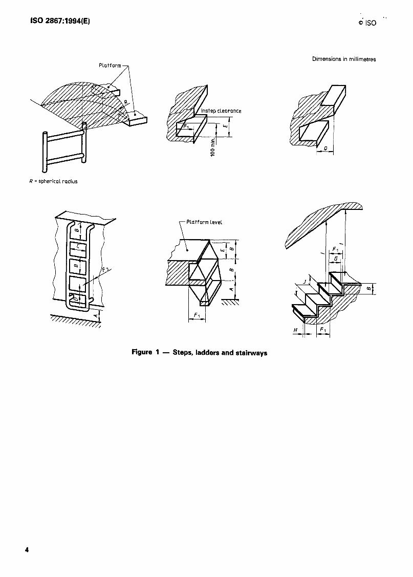
8.1 Steps shall conform to the dimensions given in figure 1 and table 1. All steps should preferably be wide enough to accommodate both feet.
6.2 Where lateral body movement is necessary from the top or bottom step of a ladder to the next stepping surface, the distance between the rung and the nearest edge of the bearing surface shall be within a spherical radius R of 300 mm max. (see fig- ure 1).
6.3 Steps shall be coordinated with properly pos- itioned handrails and handholds.
6.4 Wherever a foot can protrude through the step and contact a moving part, a shield shall be provided between the step and the moving part.
6.5 Step design shall minimize the risk of the foot slipping laterally off the step.
6.6 The step tread surface shall not be intended for use as a handhold.
6.7 Step design shall minimize accumulation of de- bris and aid in the cleaning of mud and debris from the shoe sole.
6.8 Step design shall provide the user with natural foot placement, or the steps shall be clearly visible to the user.
6.9 Flexibly-mounted series of steps should be avoided. If used, the steps shall not move more than 80 mm elastically in any plane when a horizontal force of 1 000 N is applied, centred on the outer edge of the leading edge of the first nonswinging step from the ground. The first step from the ground may be free-swinging.
3
IS0 2867:1994(E) 6 IS0 *’
Dimensions in millimetres
nce
R = spherical radius
7 Platform Level
l-4 FI
Figure 1 - Steps, ladders and stairways
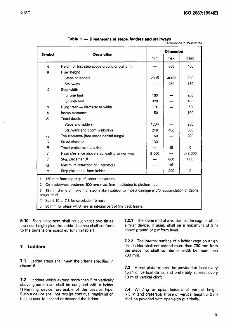
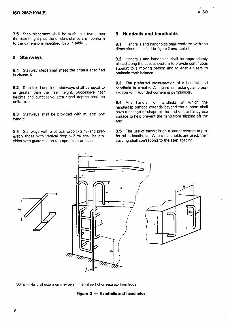
Table 1 - Dimensions of steps, ladders and stairways Dimensions in millimetres
Dimension Symbol Description
min. max. basic
A Height of first step above ground or platform - 700 400
B Riser height
Steps or ladders 230’) 4002) 300
Stairways - 250 180
C Step width
for one foot 160 - 200
for both feet 320 - 400
D Rung tread - diameter or width 19 - 60
E Instep clearance 150 - 190
Fl Tread depth:
Steps and ladders 1303) - 200
Stairways and boom walkways 240 400 300
F2 Toe clearance (free space behind rungs) 150 - 200
G Stride distance 130 - -
H Tread projection from riser - 25 0
I Head clearance above step leading to walkway 2000 - >2 000
J Step placement4) - 800 600
Q Maximum retraction of 1 step/stair - 105) - R Step placement from ladder - 300 0
1) 150 mm from top step of ladder to platform.
2) On track/wheel systems, 500 mm max. from track/step to platform top.
3) 19 mm diameter if width of step is likely subject to impact damage and/or accumulation of debris and/or mud.
4) See 6.10 or 7.5 for calculation formula.
5) 30 mm for steps which are an integral part of the track frame.
6.10 Step placement shall be such that two times 7.2.1 The lower end of a vertical ladder cage or other the riser height plus the stride distance shall conform similar device, if used, shall be a maximum of 3 m to the dimensions specified for J in table 1. above ground or platform level.
7 Ladders
7.1 Ladder steps shall meet the criteria specified in clause 6.
7.2 Ladders which extend more than 5 m vertically above ground level shall be equipped with a ladder fall-limiting device, preferably of the passive type. Such a device shall not require continual manipulation for the user to ascend or descend the ladder.
7.2.2 The internal surface of a ladder cage on a ver- tical ladder shall not extend more than 700 mm from the steps nor shall its internal width be more than 700 mm.
7.3 A rest platform shall be provided at least every 15 m of vertical climb, and preferably at least every 10 m of vertical climb.
7.4 Winding or spiral ladders of vertical height > 3 m (and preferably those of vertical height > 2 m) shall be provided with open-side guardrails.
5
IS0 2867:1994(E)
. *,
Q IS0
7.5 Step placement shall be such that two times the riser height plus the stride distance shall conform to the dimensions specified for J in table 1.
8 Stairways
8.1 Stairway steps shall meet the criteria specified in clause 6.
8.2 Step tread depth on stairways shall be equal to or greater than the riser height. Successive riser heights and successive step tread depths shall be uniform.
8.3 Stairways shall be provided with at least one handrail.
8.4 Stairways with a vertical drop > 3 m (and pref- erably those with vertical drop 7 2 m) shall be pro- vided with guardrails on the open side or sides.
9 Handrails and handholds
9.1 Handrails and handholds shall conform with the dimensions specified in figure 2 and table 2.
9.2 Handrails and handholds shall be appropriately placed along the access system to provide continuous support to a moving person and to enable users to maintain their balance.
9.3 The preferred cross-section of a handrail and handhold is circular. A square or rectangular cross- section with rounded corners is permissible.
9.4 Any handrail or handhold on which the handgrasp surface extends beyond the support shall have a change of shape at the end of the handgrasp surface to help prevent the hand from slipping off the end.
9.5 The use of handrails on a ladder system is pre- ferred to handholds. Where handholds are used, their spacing shall correspond to the step spacing.
NOTE - Handrail extension may be an integral part of or separate from ladder.
Figure 2 - Handrails and handholds
6
fJ IS0 IS0 2887:1994(E)
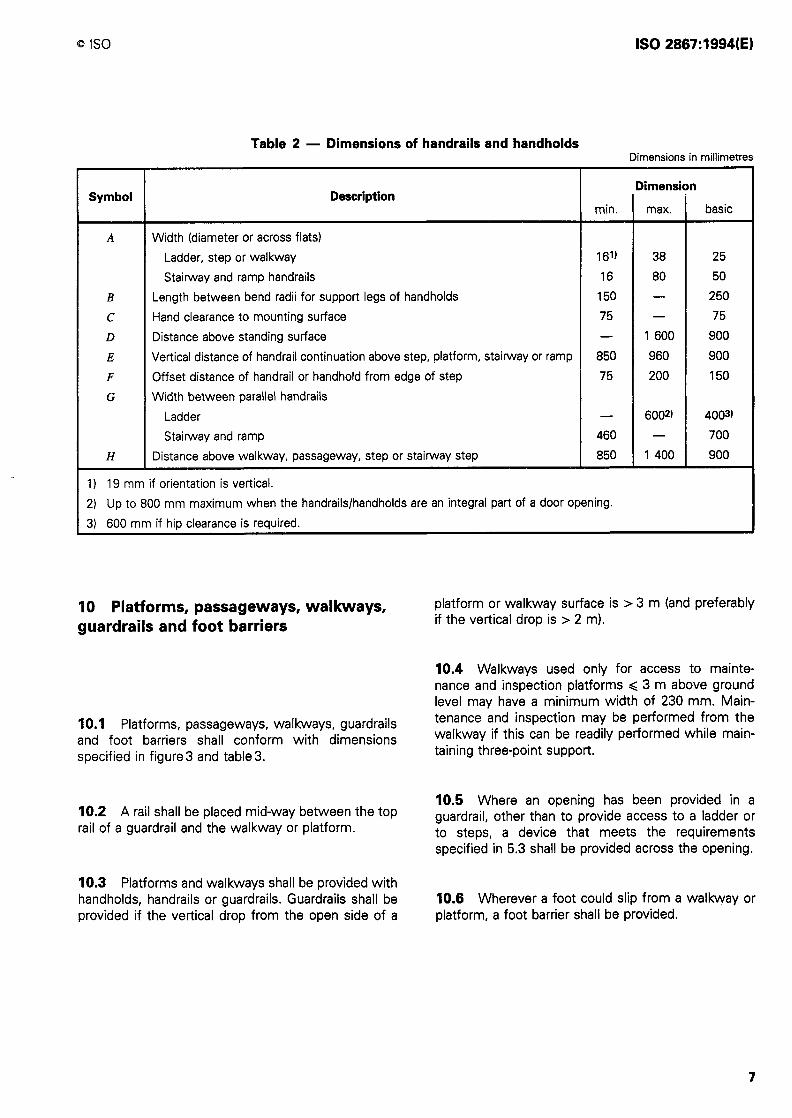
Table 2 - Dimensions of handrails and handholds Dimensions in millimetres
Description Dimension
Width (diameter or across flats)
Ladder, step or walkway Stairway and ramp handrails
Length between bend radii for support legs of handholds
Hand clearance to mounting surface
Distance above standing surface
Vertical distance of handrail continuation above step, platform, stairway or ramp
Offset distance of handrail or handhold from edge of step
Width between parallel handrails
Stairway and ramp
I) 19 mm if orientation is vertical. 2) Up to 800 mm maximum when the handrails/handholds are an integral part of a door opening.
3) 600 mm if hip clearance is required.
10 Platforms, passageways, walkways, guardrails and foot barriers
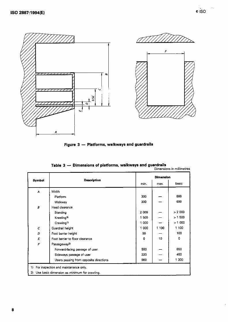
10.1 Platforms, passageways, walkways, guardrails and foot barriers shall conform with dimensions specified in figure3 and table3.
10.2 A rail shall be placed mid-way between the top rail of a guardrail and the walkway or platform.
10.3 Platforms and walkways shall be provided with handholds, handrails or guardrails. Guardrails shall be provided if the vertical drop from the open side of a
platform or walkway surface is > 3 m (and preferably if the vertical drop is > 2 m).
10.4 Walkways used only for access to mainte- nance and inspection platforms < 3 m above ground level may have a minimum width of 230 mm. Main- tenance and inspection may be performed from the walkway if this can be readily performed while main- taining three-point support.
10.5 Where an opening has been provided in a guardrail, other than to provide access to a ladder or to steps, a device that meets the requirements specified in 5.3 shall be provided across the opening.
10.6 Wherever a foot could slip from a walkway or platform, a foot barrier shall be provided.
7
IS0 2887:1994(E) 0 is0 1,
I - I
Figure 3 - Platforms, walkways and guardrails
Table 3 - Dimensions of platforms, walkways and guardrails Dimensions in millimetres
Symbol Description
A Width
Platform
Walkway
B Head clearance
Standing
Kneelingt)
CrawlingtJ
c Guardrail height
D Foot barrier height
E Foot barrier to floor clearance
F Passageway2)
Forward-facing passage of user
Sideways passage of user
Users passing from opposite directions
1) For inspection and maintenance only.
2) Use basic dimension as minimum for crawling.
min.
300
300
2 000
1 500
1 000
1 000
50
0
550
330
900
Dimension
max. basic
- 600
- 600
- > 2 000
- > 1 500
- > 1 000
1 100 1 100
- 100
10 0
- 650
- 450
- 1 300
0 IS0 IS0 2887:1994(E)
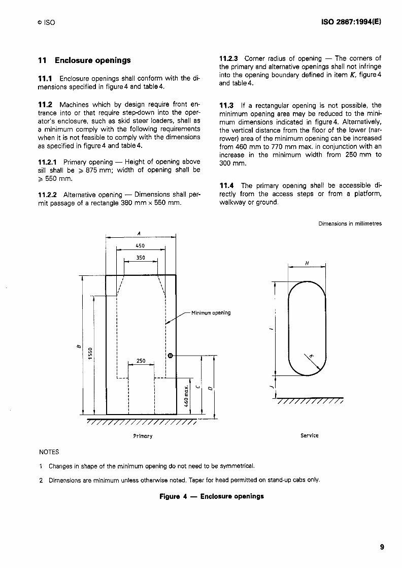
II Enclosure openings 11.2.3 Corner radius of opening - The corners of the primary and alternative openings shall not infringe into the opening boundary defined in item K, figure4 and table 4.
11.1 Enclosure openings shall conform with the di- mensions specified in figure4 and table4.
11.2 Machines which by design require front en- trance into or that require step-down into the oper- ator’s enclosure, such as skid steer loaders, shall as a minimum comply with the following requirements when it is not feasible to comply with the dimensions as specified in figure4 and table4.
11.3 If a rectangular opening is not possible, the minimum opening area may be reduced to the mini- mum dimensions indicated in figure 4. Alternatively, the vertical distance from the floor of the lower (nar- rower) area of the minimum opening can be increased from 460 mm to 770 mm max. in conjunction with an increase in the minimum width from 250 mm to 300 mm. 11.2.1 Primary opening - Height of opening above
sill shall be & 875 mm; width of opening shall be > 550 mm.
11.4 The primary opening shall be accessible di- rectly from the access steps or from a platform, walkway or ground.
11.2.2 Alternative opening - Dimensions shall per- mit passage of a rectangle 380 mm x 550 mm.
Dimensions in millimetres
A
450 -I
350
“- 1’ \ \
c \ \ \
H
I
- Minimum opening
I
a
NOTES
I 250
I@
-- l--v q-i
I I I I
I I I I I I
-
% E
% *
-
‘///////////////////
Primary Service
1 Changes in shape of the minimum opening do not need to be symmetrical.
2 Dimensions are minimum unless otherwise noted. Taper for head permitted on stand-up cabs only.
Figure 4 - Enclosure openings
9
IS0 2887:1994(E) Q is0 '
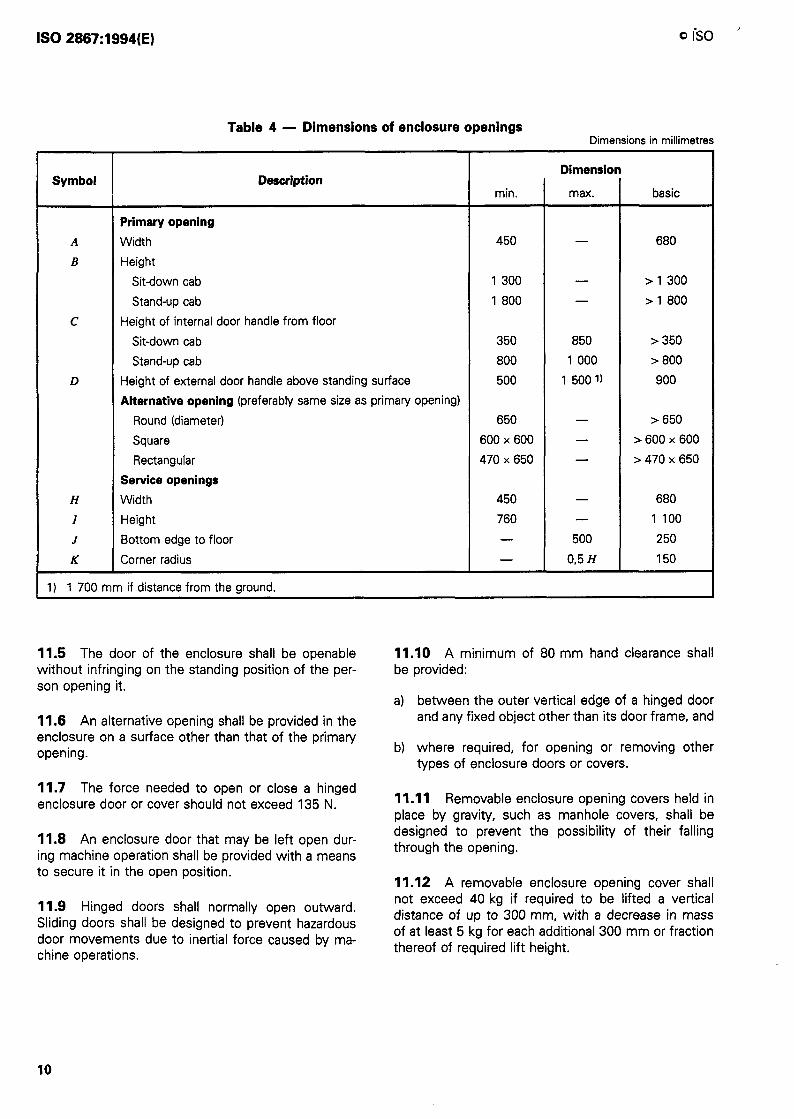
Table 4 - Dimensions of enclosure openings Dimensions in millimetres
Dimension Symbol Description
min. max. basic
Primary opening
A Width 450 - 680
B Height Sit-down cab 1 300 - > 1 300
Stand-up cab 1 800 - > 1 800
c Height of internal door handle from floor Sitdown cab 350 850 > 350
Stand-up cab 800 1 000 > 800
D Height of external door handle above standing surface 500 1 500 1) 900
Alternative opening (preferably same size as primary opening) Round (diameter) 650 - > 650
Square 600x600 - >6OOx600
Rectangular 470x650 - 1470x650
Service openings
H Width 450 - 680
I Height 760 - 1 100
J Bottom edge to floor - 500 250
K Corner radius - 0,5 H 150
1) 1 700 mm if distance from the ground.
11.5 The door of the enclosure shall be openable without infringing on the standing position of the per- son opening it.
11.8 An alternative opening shall be provided in the enclosure on a surface other than that of the primary opening.
11.7 The force needed to open or close a hinged enclosure door or cover should not exceed 135 N.
11.8 An enclosure door that may be left open dur- ing machine operation shall be provided with a means to secure it in the open position.
11.9 Hinged doors shall normally open outward. Sliding doors shall be designed to prevent hazardous door movements due to inertial force caused by ma- chine operations.
11.10 A minimum of 80 mm hand clearance shall be provided:
a) between the outer vertical edge of a hinged door and any fixed object other than its door frame, and
b) where required, for opening or removing other types of enclosure doors or covers.
11.11 Removable enclosure opening covers held in place by gravity, such as manhole covers, shall be designed to prevent the possibility of their falling through the opening.
11.12 A removable enclosure opening cover shall not exceed 40 kg if required to be lifted a vertical distance of up to 300 mm, with a decrease in mass of at least 5 kg for each additional 300 mm or fraction thereof of required lift height.
10

Annex A (informative)
Bibliography
[l] IS0 2860:1992, Earth-moving machinery - Minimum access dimensions.
IS0 2867:1994(E)


IS0 2887:1994(E)
ICS 53.100.00 r)escrip~ors: earth-moving equipment, operating stations, access facilities, access openings, specifications.
Price based on 11 pages