Embed Size (px)
Citation preview
Isilon Network Design Considerations © 2017 Dell Inc.
ISILON NETWORK DESIGN CONSIDERATIONS
ABSTRACT
This white paper explores design considerations of Isilon’s external network to ensure
maximum performance and an optimal user experience.
Version 3.2
January 2018
Partner Branding
Logo Flex
82x44px White Paper
2 | Isilon Network Design Considerations
© 2017 Dell Inc.
TABLE OF CONTENTS
EXECUTIVE SUMMARY ...........................................................................................................4
NOTICE TO READERS .............................................................................................................4
VERSION HISTORY ..................................................................................................................4
NETWORK ARCHITECTURE DESIGN.....................................................................................5
General Network Architecture Considerations................................................................................... 5
Triangle Looped Topology ................................................................................................................. 6
Link Aggregation ............................................................................................................................... 7
Multi-Chassis Link Aggregation .................................................................................................................. 7
LATENCY, BANDWIDTH & THROUGHPUT ............................................................................8
Latency .............................................................................................................................................. 8
Bandwidth & Throughput ................................................................................................................... 8
Bandwidth Delay Product ........................................................................................................................... 9
Isilon Network Stack Tuning ..................................................................................................................... 10
ETHERNET FLOW CONTROL ................................................................................................11
ETHERNET, MTU, & IP OVERHEAD ......................................................................................12
Ethernet Packet ............................................................................................................................... 12
Ethernet Payload ..................................................................................................................................... 13
Jumbo Frames ................................................................................................................................ 13
IP Packet Overhead ........................................................................................................................ 14
Example 1: Standard 1500 Byte Payload – IPv4 / TCP ............................................................................ 14
Example 2: Jumbo 9000 Byte Payload – IPv4 / TCP ................................................................................ 14
Example 3: Standard 1500 Byte Payload – IPv4 / TCP / Linux TimeStamp .............................................. 15
Example 4: Jumbo 9000 Byte Payload – IPv4 / TCP / Linux Timestamp .................................................. 15
Data Payload to Ethernet Frame Effeciency ............................................................................................. 15
ICMP and MTU With Isilon .............................................................................................................. 16
Isilon OneFS MTU Commands........................................................................................................ 16
Confirming Transmitted MTU .......................................................................................................... 16
IPV6 ..........................................................................................................................................17
Why IPv6? ....................................................................................................................................... 17
Security .................................................................................................................................................... 17
Efficiency ................................................................................................................................................. 17
Multicast .................................................................................................................................................. 17
3 | Isilon Network Design Considerations
© 2017 Dell Inc.
Quality of Service ..................................................................................................................................... 17
IPv6 Addressing .............................................................................................................................. 18
IPv6 Header .................................................................................................................................... 19
IPv6 to IPv4 Translation .................................................................................................................. 19
Configuring Isilon OneFS for IPv6 ................................................................................................... 19
NETWORK TROUBLESHOOTING .........................................................................................20
Netstat ............................................................................................................................................. 20
netstat ...................................................................................................................................................... 20
netstat –s –p tcp....................................................................................................................................... 21
netstat –i .................................................................................................................................................. 22
netstat –m ................................................................................................................................................ 23
InsightIQ External Network Errors ................................................................................................... 24
DNS ................................................................................................................................................. 26
NETWORKING TOOLS ...........................................................................................................27
REFERENCES .........................................................................................................................27

4 | Isilon Network Design Considerations
© 2017 Dell Inc.
EXECUTIVE SUMMARY
This document provides design considerations for understanding, configuring, and troubleshooting Isilon Scale-Out NAS external
networking. In a Scale-Out NAS environment, the overall network architecture must be configured to maximize the user experience.
Many factors contribute to overall network performance. This document examines network architecture design and best practices
including factors such as Latency, Flow Control, ICMP, MTU, jumbo frames, congestion, TCP/IP parameters, and IPv6.
NOTICE TO READERS
It is important to understand that the network design considerations stated in this document are based on general network design and
are provided as guidance to Isilon administrators. As these are considerations, all of these may not apply to each workload. It is
important to understand each consideration and confirm if it pertains to a specific environment.
Each network is unique, not only from a design perspective but also from a requirements and workloads perspective. Before making
any changes based on the guidance in this document, it is important to discuss modifications with the Network Engineering team.
Additionally, as a customary requirement for any major IT implementation, changes should first be tested in a lab environment that
closely mimics the workloads of the live network.
VERSION HISTORY
Version Date Comments
1.0 March 2017 Initial Rough Draft
2.0 July 2017 Updated after several reviews and posted online
3.0 November 2017 Updated after additional feedback.
Updated title from “Isilon Advanced Networking Fundamentals” to “Isilon Network Design Considerations.”
Updated the following sections with additional details:
Link Aggregation
Jumbo Frames
Latency
ICMP & MTU
New sections added:
MTU Framesize Overhead
Ethernet Frame
Network Troubleshooting
3.1 December 2017 Added link to Network Stack Tuning spreadsheet
Added Multi-Chassis Link Aggregation
3.2 January 2018 Removed switch-specific configuration steps with a note for contacting manufacturer
Updated section title for Confirming Transmitted MTUs
Added OneFS commands for checking and modifying MTU
Updated Jumbo Frames section
3.3 May 2018 Updated equation for Bandwidth Delay Product
5 | Isilon Network Design Considerations
© 2017 Dell Inc.
NETWORK ARCHITECTURE DESIGN
The architecture design is the core foundation of a reliable and highly available network, taking into account capacity and bandwidth.
Layered on top of the basic foundation are the many applications running on a campus network with each requiring specific features
and considerations.
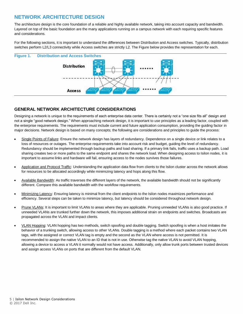
For the following sections, it is important to understand the differences between Distribution and Access switches. Typically, distribution
switches perform L2/L3 connectivity while Access switches are strictly L2. The Figure below provides the representation for each.
Figure 1. Distribution and Access Switches
GENERAL NETWORK ARCHITECTURE CONSIDERATIONS
Designing a network is unique to the requirements of each enterprise data center. There is certainly not a “one size fits all” design and
not a single “good network design.” When approaching network design, it is important to use principles as a leading factor, coupled with
the enterprise requirements. The requirements must include current and future application consumption, providing the guiding factor in
major decisions. Network design is based on many concepts; the following are considerations and principles to guide the process:
Single Points of Failure: Ensure the network design has layers of redundancy. Dependence on a single device or link relates to a
loss of resources or outages. The enterprise requirements take into account risk and budget, guiding the level of redundancy.
Redundancy should be implemented through backup paths and load sharing. If a primary link fails, traffic uses a backup path. Load
sharing creates two or more paths to the same endpoint and shares the network load. When designing access to Isilon nodes, it is
important to assume links and hardware will fail, ensuring access to the nodes survives those failures.
Application and Protocol Traffic: Understanding the application data flow from clients to the Isilon cluster across the network allows
for resources to be allocated accordingly while minimizing latency and hops along this flow.
Available Bandwidth: As traffic traverses the different layers of the network, the available bandwidth should not be significantly
different. Compare this available bandwidth with the workflow requirements.
Minimizing Latency: Ensuring latency is minimal from the client endpoints to the Isilon nodes maximizes performance and
efficiency. Several steps can be taken to minimize latency, but latency should be considered throughout network design.
Prune VLANs: It is important to limit VLANs to areas where they are applicable. Pruning unneeded VLANs is also good practice. If
unneeded VLANs are trunked further down the network, this imposes additional strain on endpoints and switches. Broadcasts are
propagated across the VLAN and impact clients.
VLAN Hopping: VLAN hopping has two methods, switch spoofing and double tagging. Switch spoofing is when a host imitates the
behavior of a trunking switch, allowing access to other VLANs. Double tagging is a method where each packet contains two VLAN
tags, with the assigned or correct VLAN tag is empty and the second as the VLAN where access is not permitted. It is
recommended to assign the native VLAN to an ID that is not in use. Otherwise tag the native VLAN to avoid VLAN hopping,
allowing a device to access a VLAN it normally would not have access. Additionally, only allow trunk ports between trusted devices
and assign access VLANs on ports that are different from the default VLAN.
6 | Isilon Network Design Considerations
© 2017 Dell Inc.
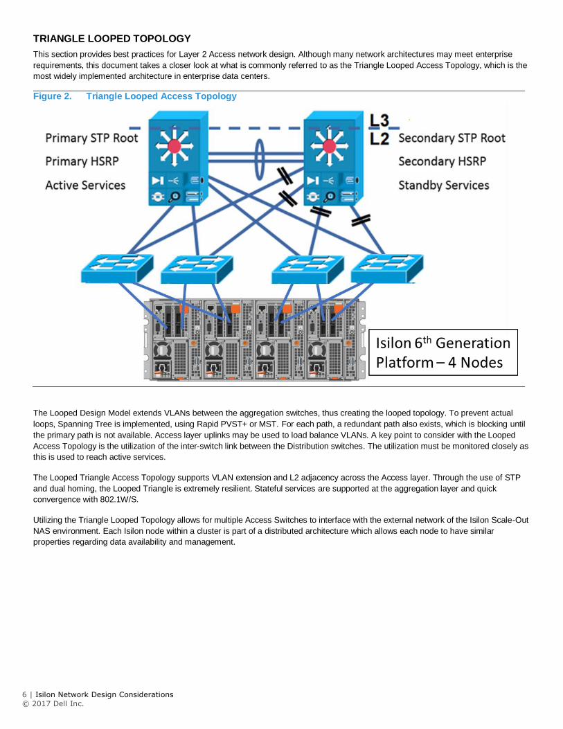
TRIANGLE LOOPED TOPOLOGY
This section provides best practices for Layer 2 Access network design. Although many network architectures may meet enterprise
requirements, this document takes a closer look at what is commonly referred to as the Triangle Looped Access Topology, which is the
most widely implemented architecture in enterprise data centers.
Figure 2. Triangle Looped Access Topology
The Looped Design Model extends VLANs between the aggregation switches, thus creating the looped topology. To prevent actual
loops, Spanning Tree is implemented, using Rapid PVST+ or MST. For each path, a redundant path also exists, which is blocking until
the primary path is not available. Access layer uplinks may be used to load balance VLANs. A key point to consider with the Looped
Access Topology is the utilization of the inter-switch link between the Distribution switches. The utilization must be monitored closely as
this is used to reach active services.
The Looped Triangle Access Topology supports VLAN extension and L2 adjacency across the Access layer. Through the use of STP
and dual homing, the Looped Triangle is extremely resilient. Stateful services are supported at the aggregation layer and quick
convergence with 802.1W/S.
Utilizing the Triangle Looped Topology allows for multiple Access Switches to interface with the external network of the Isilon Scale-Out
NAS environment. Each Isilon node within a cluster is part of a distributed architecture which allows each node to have similar
properties regarding data availability and management.
7 | Isilon Network Design Considerations
© 2017 Dell Inc.
LINK AGGREGATION
In the context of the IEEE 802.1AX standard, link aggregation provides methods to combine multiple Ethernet interfaces, forming a
single link layer interface, specific to a switch or server. Therefore, link aggregation is implemented between a single switch and an
Isilon node, not across Isilon nodes.
Implementing link aggregation is neither mandatory nor is it necessary, rather it is based on workload requirements and is
recommended if a transparent failover or switch port redundancy is required.
Link aggregation assumes all links are full duplex, point to point, and at the same data rate, providing graceful recovery from link
failures. If a link fails, traffic is automatically sent to the next available link without disruption.
It is imperative to understand that link aggregation is not a substitute for a higher bandwidth link. Although link aggregation combines
multiple interfaces, applying it to multiply bandwidth by the number of interfaces for a single session is incorrect. Link aggregation
distributes traffic across links. However, a single session only utilizes a single physical link to ensure packets are delivered in order
without duplication of frames.
As part of the IEEE 802.1AX standard, the Frame Distributor does not specify a distribution algorithm across aggregated links, but
enforces that frames must be sent in order without duplication. Frame order is maintained by ensuring that all frames of a given session
are transmitted on a single link in the order that they are generated by the client. The mandate does not allow for additions or
modifications to the MAC frame, buffering, or processing to re-order frames by the Frame Distributor or Collector.
Thus, the bandwidth for a single client is not increased, but the aggregate bandwidth of all clients increases in an active/active
configuration. The aggregate bandwidth is realized when carrying multiple simultaneous sessions and may not provide a linear multiple
of each link’s data rate, as each individual session utilizes a single link.
Another factor to consider is depending on the workload, certain protocols may or may not benefit from link aggregation. Stateful
protocols, such as NFSv4 and SMBv2 benefit from link aggregation as a failover mechanism. On the contrary, SMBv3 Multichannel
automatically detects multiple links, utilizing each for maximum throughput and link resilience.
Table 1. Link Aggregation
Link Aggregation Advantages Link Aggregation Limitations
Higher aggregate bandwidth for multiple sessions. A single session is confined to a single link.
Provides resiliency for interface and cabling failures, but not for switch failures.
Link resiliency Bandwidth for a single session is not improved as a single link is used for each session.
Ease of management with a single IP address Depending on the workload, each protocol has varying limitations and advantages of Link Aggregation Load balancing
MULTI-CHASSIS LINK AGGREGATION
As discussed in the previous section, the IEEE 802.1AX standard does not define Link Aggregation between multiple switches and an
Isilon node. However, many vendors provide this functionality through proprietary features. Multiple switches are connected with an
Inter-Switch link or other proprietary cable and communicate via a proprietary protocol forming a virtual switch. A virtual switch is
perceived as a single switch to an Isilon node, with links terminating on a single switch. The ability to have link aggregation split with
multiple chassis provides network redundancy if a single chassis were to fail.
Each vendor has a proprietary implementation of Multi-Chassis Link Aggregation, but externally the virtual switch created is compliant
with the IEEE 802.1AX standard.
It is important to recognize that regarding bandwidth, the concepts discussed for single switch Link Aggregation still apply to Multi-
Chassis Link Aggregation. Additionally, as the multiple switches form a single virtual switch, it is important to understand what happens
if the switch hosting the control plane fails. Those effects vary by the vendor’s implementation but will impact the network redundancy
gained through Multi-Chassis Link Aggregation.
8 | Isilon Network Design Considerations
© 2017 Dell Inc.
LATENCY, BANDWIDTH & THROUGHPUT
Maximizing overall network performance is dependent on several factors. However, the three biggest factors contributing to end-to-end
performance are latency, throughput, and bandwidth. This section focuses on these factors to maximize the Isilon user experience.
LATENCY
Latency in a packet-switched network is defined as the time from when a source endpoint sends a packet to when it is received by the
destination endpoint. Round trip latency, sometimes referred to as round-trip delay, is the amount of time for a packet to be sent from
the source endpoint to the destination endpoint, and returned from the destination to the source endpoint.
Minimal latency in any transaction is imperative for several reasons. IP endpoints, switches, and routers operate optimally without
network delays. Minimal latency between clients and an Isilon node ensures performance is not impacted. As latency increases
between two endpoints, this may lead to several issues that degrade performance heavily, depending on the application.
In order to minimize latency, it is important to measure it accurately between the endpoints. For assessing Isilon nodes, this is
measured from the clients to a specified node. The measurement could use the IP of a specific node or the SmartConnect hostname.
After configuration changes are applied that impact latency, it is important to confirm the latency has indeed decreased. When
attempting to minimize latency, consider the following points:
Hops: Minimizing hops required between endpoints decreases latency. The implication is not to drag cables across a campus, but
the goal is to confirm if any unnecessary hops could be avoided. Minimizing hops applies at the physical level with the number of
switches between the endpoints but also applies logically to network protocols and algorithms.
ASICs: When thinking about network hops it also important to consider the ASICs within a switch. If a packet enters through one
ASIC and exits through the other, latency could increase. If at all possible, it is recommended to keep traffic as part of the same
ASIC to minimize latency.
Network Congestion: NFS v3, NFSv4 and SMB employ the TCP protocol. For reliability and throughput, TCP uses windowing to
adapt to varying network congestion. At peak traffic, congestion control is triggered, dropping packets, and leading TCP to utilize
smaller windows. In turn, throughput could decrease, and overall latency may increase. Minimizing network congestion ensures it
does not impact latency. It is important to architect networks that are resilient to congestion.
Routing: Packets that pass through a router may induce additional latency. Depending on the router configuration, packets are
checked for a match against defined rules, in some cases requiring packet header modification.
MTU Mismatch: Depending on the MTU size configuration of each hop between two endpoints, an MTU mismatch may exist.
Therefore, packets must be split to conform to upstream links, creating additional CPU overhead on routers and NICs, creating
higher processing times, and leading to additional latency.
Firewalls: Firewalls provide protection by filtering through packets against set rules for additional steps. The filtering process
consumes time and could create further latency. Processing times are heavily dependent upon the number of rules in place. It is
good measure to ensure outdated rules are removed to minimize processing times.
BANDWIDTH & THROUGHPUT
Understanding the difference between throughput and bandwidth are important for network troubleshooting. Although these terms are
conflated at times, they are actually both unique. Bandwidth is the theoretical maximum speed a specific medium can deliver if all
factors are perfect without any form of interference. Throughput is the actual speed realized in a real-world scenario, given interference
and other environmental factors such as configuration, contention, and congestion.
The difference between these terms is important when troubleshooting. If an Isilon node supports 40 GbE, it does not necessarily mean
the throughput is 40 Gb/s. The actual throughput between a client and an Isilon node is dependent on all of the factors between the two
endpoints and may be measured with a variety of tools.
During the design phase of a data center network, it is important to ensure bandwidth is available throughout the hierarchy, eliminating
bottlenecks and ensuring consistent bandwidth. The bandwidth from the Access Switches to the Isilon nodes should be a ratio of what
is available back to the distribution and core switches. For example, if an Isilon cluster of 12 nodes has all 40 GbE connectivity to
access switches, the link from the core to distribution to access should be able to handle the throughput from the access switches.
Ideally, the link from the core to distribution to access should support roughly a bandwidth of 480 Gb (12 nodes * 40 GbE).
9 | Isilon Network Design Considerations
© 2017 Dell Inc.
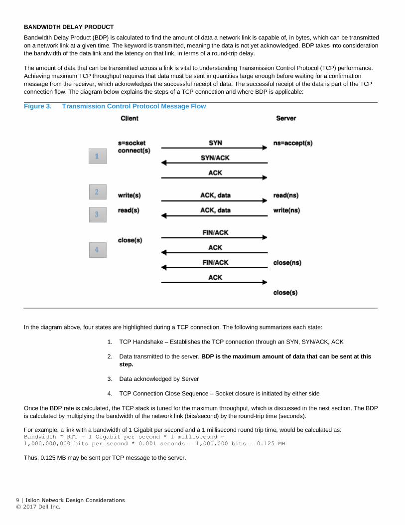
BANDWIDTH DELAY PRODUCT
Bandwidth Delay Product (BDP) is calculated to find the amount of data a network link is capable of, in bytes, which can be transmitted
on a network link at a given time. The keyword is transmitted, meaning the data is not yet acknowledged. BDP takes into consideration
the bandwidth of the data link and the latency on that link, in terms of a round-trip delay.
The amount of data that can be transmitted across a link is vital to understanding Transmission Control Protocol (TCP) performance.
Achieving maximum TCP throughput requires that data must be sent in quantities large enough before waiting for a confirmation
message from the receiver, which acknowledges the successful receipt of data. The successful receipt of the data is part of the TCP
connection flow. The diagram below explains the steps of a TCP connection and where BDP is applicable:
Figure 3. Transmission Control Protocol Message Flow
In the diagram above, four states are highlighted during a TCP connection. The following summarizes each state:
1. TCP Handshake – Establishes the TCP connection through an SYN, SYN/ACK, ACK
2. Data transmitted to the server. BDP is the maximum amount of data that can be sent at this
step.
3. Data acknowledged by Server
4. TCP Connection Close Sequence – Socket closure is initiated by either side
Once the BDP rate is calculated, the TCP stack is tuned for the maximum throughput, which is discussed in the next section. The BDP
is calculated by multiplying the bandwidth of the network link (bits/second) by the round-trip time (seconds).
For example, a link with a bandwidth of 1 Gigabit per second and a 1 millisecond round trip time, would be calculated as: Bandwidth * RTT = 1 Gigabit per second * 1 millisecond =
1,000,000,000 bits per second * 0.001 seconds = 1,000,000 bits = 0.125 MB
Thus, 0.125 MB may be sent per TCP message to the server.
10 | Isilon Network Design Considerations
© 2017 Dell Inc.
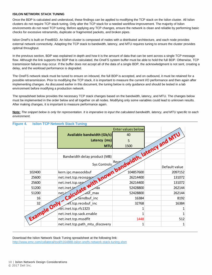
ISILON NETWORK STACK TUNING
Once the BDP is calculated and understood, these findings can be applied to modifying the TCP stack on the Isilon cluster. All Isilon
clusters do not require TCP stack tuning. Only alter the TCP stack for a needed workflow improvement. The majority of Isilon
environments do not need TCP tuning. Before applying any TCP changes, ensure the network is clean and reliable by performing basic
checks for excessive retransmits, duplicate or fragmented packets, and broken pipes.
Isilon OneFs is built on FreeBSD. An Isilon cluster is composed of nodes with a distributed architecture, and each node provides
external network connectivity. Adapting the TCP stack to bandwidth, latency, and MTU requires tuning to ensure the cluster provides
optimal throughput.
In the previous section, BDP was explained in depth and how it is the amount of data that can be sent across a single TCP message
flow. Although the link supports the BDP that is calculated, the OneFS system buffer must be able to hold the full BDP. Otherwise, TCP
transmission failures may occur. If the buffer does not accept all of the data of a single BDP, the acknowledgment is not sent, creating a
delay, and the workload performance is degraded.
The OneFS network stack must be tuned to ensure on inbound, the full BDP is accepted, and on outbound, it must be retained for a
possible retransmission. Prior to modifying the TCP stack, it is important to measure the current I/O performance and then again after
implementing changes. As discussed earlier in this document, the tuning below is only guidance and should be tested in a lab
environment before modifying a production network.
The spreadsheet below provides the necessary TCP stack changes based on the bandwidth, latency, and MTU. The changes below
must be implemented in the order below and all together on all nodes. Modifying only some variables could lead to unknown results.
After making changes, it is important to measure performance again.
Note: The snippet below is only for representation. It is imperative to input the calculated bandwidth, latency, and MTU specific to each
environment.
Figure 4. Isilon TCP Network Stack Tuning
Download the Isilon Network Stack Tuning spreadsheet at the following link:
http://www.emc.com/collateral/tool/h164888-isilon-onefs-network-stack-tuning.xlsm
Enter values below
Available bandwidth (Gb/s) 40
Latency (ms) 5
MTU 1500
Bandwidth delay product (MB) 25
Sys ControlsRecommended
value Default value
102400 kern.ipc.maxsockbuf 104857600 2097152
25600 net.inet.tcp.recvspace 26214400 131072
25600 net.inet.tcp.sendspace 26214400 131072
51200 net.inet.tcp.sendbuf_max 52428800 262144
51200 net.inet.tcp.recvbuf_max 52428800 262144
16 net.inet.tcp.sendbuf_inc 16384 8192
32 net.inet.tcp.recvbuf_inc 32768 16384
net.inet.tcp.rfc1323 1 1
net.inet.tcp.sack.enable 1 1
net.inet.tcp.mssdflt 1448 512
net.inet.tcp.path_mtu_discovery 1 1
11 | Isilon Network Design Considerations
© 2017 Dell Inc.
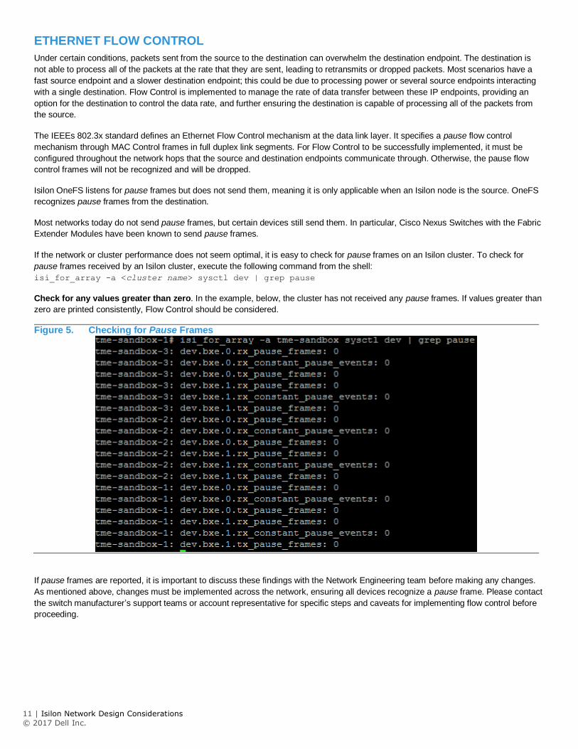
ETHERNET FLOW CONTROL
Under certain conditions, packets sent from the source to the destination can overwhelm the destination endpoint. The destination is
not able to process all of the packets at the rate that they are sent, leading to retransmits or dropped packets. Most scenarios have a
fast source endpoint and a slower destination endpoint; this could be due to processing power or several source endpoints interacting
with a single destination. Flow Control is implemented to manage the rate of data transfer between these IP endpoints, providing an
option for the destination to control the data rate, and further ensuring the destination is capable of processing all of the packets from
the source.
The IEEEs 802.3x standard defines an Ethernet Flow Control mechanism at the data link layer. It specifies a pause flow control
mechanism through MAC Control frames in full duplex link segments. For Flow Control to be successfully implemented, it must be
configured throughout the network hops that the source and destination endpoints communicate through. Otherwise, the pause flow
control frames will not be recognized and will be dropped.
Isilon OneFS listens for pause frames but does not send them, meaning it is only applicable when an Isilon node is the source. OneFS
recognizes pause frames from the destination.
Most networks today do not send pause frames, but certain devices still send them. In particular, Cisco Nexus Switches with the Fabric
Extender Modules have been known to send pause frames.
If the network or cluster performance does not seem optimal, it is easy to check for pause frames on an Isilon cluster. To check for
pause frames received by an Isilon cluster, execute the following command from the shell:
isi_for_array -a <cluster name> sysctl dev | grep pause
Check for any values greater than zero. In the example, below, the cluster has not received any pause frames. If values greater than
zero are printed consistently, Flow Control should be considered.
Figure 5. Checking for Pause Frames
If pause frames are reported, it is important to discuss these findings with the Network Engineering team before making any changes.
As mentioned above, changes must be implemented across the network, ensuring all devices recognize a pause frame. Please contact
the switch manufacturer’s support teams or account representative for specific steps and caveats for implementing flow control before
proceeding.
12 | Isilon Network Design Considerations
© 2017 Dell Inc.
ETHERNET, MTU, & IP OVERHEAD
A Maximum Transmission Unit (MTU) is the largest packet size or frame, which may be sent along a link. The MTU is specified in
octets and is utilized by TCP to determine the maximum size of a packet per transmission. A large MTU size provides less overhead as
packet headers and acknowledgments are not consuming space and bandwidth. However, this could lead to retransmissions or drops if
a hop does not support it. On the contrary, a small MTU size is not as efficient as overhead increases with packet headers and
acknowledgments.
Generally speaking, the MTU across the internet is 1500 bytes. As such, most devices limit packet size to roughly 1472 bytes, allowing
for additional overhead and remaining under the 1500 byte limit. Additional overhead may be added as the packet goes through
different hops. The IEEE 802.3 standard also specifies 1500 bytes as the standard payload.
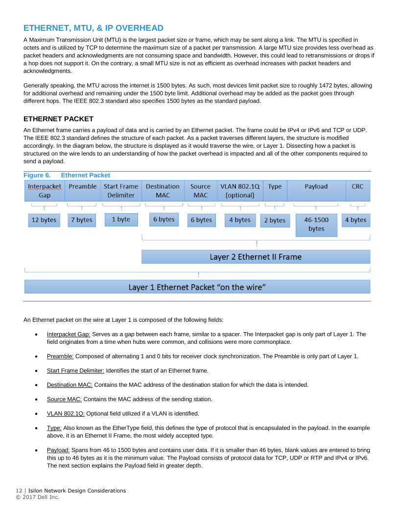
ETHERNET PACKET
An Ethernet frame carries a payload of data and is carried by an Ethernet packet. The frame could be IPv4 or IPv6 and TCP or UDP.
The IEEE 802.3 standard defines the structure of each packet. As a packet traverses different layers, the structure is modified
accordingly. In the diagram below, the structure is displayed as it would traverse the wire, or Layer 1. Dissecting how a packet is
structured on the wire lends to an understanding of how the packet overhead is impacted and all of the other components required to
send a payload.
Figure 6. Ethernet Packet
An Ethernet packet on the wire at Layer 1 is composed of the following fields:
Interpacket Gap: Serves as a gap between each frame, similar to a spacer. The Interpacket gap is only part of Layer 1. The
field originates from a time when hubs were common, and collisions were more commonplace.
Preamble: Composed of alternating 1 and 0 bits for receiver clock synchronization. The Preamble is only part of Layer 1.
Start Frame Delimiter: Identifies the start of an Ethernet frame.
Destination MAC: Contains the MAC address of the destination station for which the data is intended.
Source MAC: Contains the MAC address of the sending station.
VLAN 802.1Q: Optional field utilized if a VLAN is identified.
Type: Also known as the EtherType field, this defines the type of protocol that is encapsulated in the payload. In the example
above, it is an Ethernet II Frame, the most widely accepted type.
Payload: Spans from 46 to 1500 bytes and contains user data. If it is smaller than 46 bytes, blank values are entered to bring
this up to 46 bytes as it is the minimum value. The Payload consists of protocol data for TCP, UDP or RTP and IPv4 or IPv6.
The next section explains the Payload field in greater depth.
13 | Isilon Network Design Considerations
© 2017 Dell Inc.
CRC: Cyclic Redundancy Check is part of the Frame Check Sequence (FCS) to detect errors within the frame. The CRC code
should result in a zero if the data does not contain any errors.
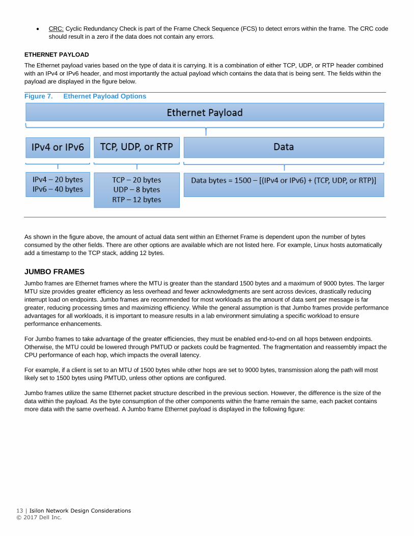
ETHERNET PAYLOAD
The Ethernet payload varies based on the type of data it is carrying. It is a combination of either TCP, UDP, or RTP header combined
with an IPv4 or IPv6 header, and most importantly the actual payload which contains the data that is being sent. The fields within the
payload are displayed in the figure below.
Figure 7. Ethernet Payload Options
As shown in the figure above, the amount of actual data sent within an Ethernet Frame is dependent upon the number of bytes
consumed by the other fields. There are other options are available which are not listed here. For example, Linux hosts automatically
add a timestamp to the TCP stack, adding 12 bytes.
JUMBO FRAMES
Jumbo frames are Ethernet frames where the MTU is greater than the standard 1500 bytes and a maximum of 9000 bytes. The larger
MTU size provides greater efficiency as less overhead and fewer acknowledgments are sent across devices, drastically reducing
interrupt load on endpoints. Jumbo frames are recommended for most workloads as the amount of data sent per message is far
greater, reducing processing times and maximizing efficiency. While the general assumption is that Jumbo frames provide performance
advantages for all workloads, it is important to measure results in a lab environment simulating a specific workload to ensure
performance enhancements.
For Jumbo frames to take advantage of the greater efficiencies, they must be enabled end-to-end on all hops between endpoints.
Otherwise, the MTU could be lowered through PMTUD or packets could be fragmented. The fragmentation and reassembly impact the
CPU performance of each hop, which impacts the overall latency.
For example, if a client is set to an MTU of 1500 bytes while other hops are set to 9000 bytes, transmission along the path will most
likely set to 1500 bytes using PMTUD, unless other options are configured.
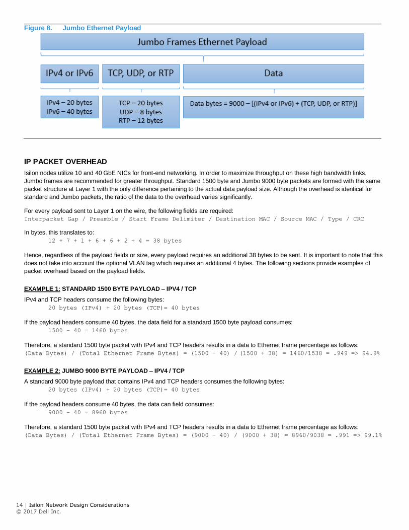
Jumbo frames utilize the same Ethernet packet structure described in the previous section. However, the difference is the size of the
data within the payload. As the byte consumption of the other components within the frame remain the same, each packet contains
more data with the same overhead. A Jumbo frame Ethernet payload is displayed in the following figure:
14 | Isilon Network Design Considerations
© 2017 Dell Inc.
Figure 8. Jumbo Ethernet Payload
IP PACKET OVERHEAD
Isilon nodes utilize 10 and 40 GbE NICs for front-end networking. In order to maximize throughput on these high bandwidth links,
Jumbo frames are recommended for greater throughput. Standard 1500 byte and Jumbo 9000 byte packets are formed with the same
packet structure at Layer 1 with the only difference pertaining to the actual data payload size. Although the overhead is identical for
standard and Jumbo packets, the ratio of the data to the overhead varies significantly.
For every payload sent to Layer 1 on the wire, the following fields are required:
Interpacket Gap / Preamble / Start Frame Delimiter / Destination MAC / Source MAC / Type / CRC
In bytes, this translates to:
12 + 7 + 1 + 6 + 6 + 2 + 4 = 38 bytes
Hence, regardless of the payload fields or size, every payload requires an additional 38 bytes to be sent. It is important to note that this
does not take into account the optional VLAN tag which requires an additional 4 bytes. The following sections provide examples of
packet overhead based on the payload fields.
EXAMPLE 1: STANDARD 1500 BYTE PAYLOAD – IPV4 / TCP
IPv4 and TCP headers consume the following bytes:
20 bytes (IPv4) + 20 bytes (TCP)= 40 bytes
If the payload headers consume 40 bytes, the data field for a standard 1500 byte payload consumes:
1500 – 40 = 1460 bytes
Therefore, a standard 1500 byte packet with IPv4 and TCP headers results in a data to Ethernet frame percentage as follows:
(Data Bytes) / (Total Ethernet Frame Bytes) = (1500 – 40) / (1500 + 38) = 1460/1538 = .949 => 94.9%
EXAMPLE 2: JUMBO 9000 BYTE PAYLOAD – IPV4 / TCP
A standard 9000 byte payload that contains IPv4 and TCP headers consumes the following bytes:
20 bytes (IPv4) + 20 bytes (TCP)= 40 bytes
If the payload headers consume 40 bytes, the data can field consumes:
9000 – 40 = 8960 bytes
Therefore, a standard 1500 byte packet with IPv4 and TCP headers results in a data to Ethernet frame percentage as follows:
(Data Bytes) / (Total Ethernet Frame Bytes) = (9000 – 40) / (9000 + 38) = 8960/9038 = .991 => 99.1%
15 | Isilon Network Design Considerations
© 2017 Dell Inc.
EXAMPLE 3: STANDARD 1500 BYTE PAYLOAD – IPV4 / TCP / LINUX TIMESTAMP
Linux automaticlly inserts the timestamp within the payload. A standard 1500 byte payload that contains IPv4, TCP, and timestamp
headers consumes the following bytes:
20 bytes (IPv4) + 20 bytes (TCP) + 12 bytes (timestamp) = 52 bytes
If the payload headers consume 40 bytes, the data field consumes:
1500 – 52 = 1448 bytes
Therefore, a standard 1500 byte packet with IPv4 and TCP headers results in a data to Ethernet frame percentage as follows:
(Data Bytes) / (Total Ethernet Frame Bytes) = (1500 – 52) / (1500 + 38) = 1448/1538 = .941 => 94.1%
EXAMPLE 4: JUMBO 9000 BYTE PAYLOAD – IPV4 / TCP / LINUX TIMESTAMP
Linux automaticlly inserts the timestamp within the payload. A standard 9000 byte payload that contains IPv4, TCP and timestamp
headers consumes the following bytes:
20 bytes (IPv4) + 20 bytes (TCP) + 12 bytes (timestamp) = 52 bytes
If the payload headers consume 40 bytes, the data field consumes:
9000 – 52 = 8948 bytes
Therefore, a standard 1500 byte packet with IPv4 and TCP headers results in a data to Ethernet frame percentage as follows:
(Data Bytes) / (Total Ethernet Frame Bytes) = (9000 – 52) / (9000 + 38) = 8948/9038 = .990 => 99.0%
DATA PAYLOAD TO ETHERNET FRAME EFFECIENCY
Utilizing the calculations above, the table below provides additional examples of the amount of data that is sent per Ethernet frame for
standard and Jumbo frames.
Table 2. Data Payload to Ethernet Frame Percentage
Note: NFS v2 is UDP. NFS v3 and v4 are TCP. SMB is TCP.
As shown in the table above, Jumbo frames deliver between 98%-99% efficiency depending on the packet type. The efficiencies are
only maximized when all hops from the client endpoint to an Isilon node support Jumbo frames. Otherwise, packets may be fragmented
leading to additional processing overhead on devices or PMTUD finding the lowest MTU along the path. Therefore, Jumbo frames are
recommended for optimal performance. However, it is important to recognize that each workload environment is unique and measuring
performance enhancements in a lab are recommended prior to a production network update.
Standard Frame Jumbo Frame
IPv4 / TCP 94.93% 99.14%
IPv4 / TCP / Linux Timestamp 94.15% 99.00%
IPv4 / TCP / Linux Timestamp / VLAN 93.90% 98.96%
IPv6 / TCP 93.63% 98.92%
IPv6 / TCP / Linux Timestamp 92.85% 98.78%
IPv6 / TCP / Linux Timestamp / VLAN 92.59% 98.74%
IPv4 / UDP 95.71% 99.27%
IPv4 / UDP / Linux Timestamp 94.93% 99.14%
IPv4 / UDP / Linux Timestamp / VLAN 94.67% 99.09%
IPv6 / UDP 94.41% 99.05%
IPv6 / UDP / Linux Timestamp 93.63% 98.92%
IPv6 / UDP / Linux Timestamp / VLAN 93.37% 98.87%
Data to Ethernet Frame PercentagePacket Type
16 | Isilon Network Design Considerations
© 2017 Dell Inc.
ICMP AND MTU WITH ISILON
Network devices employ Internet Control Message Protocol (ICMP) to gather communications related information. ICMP is capable of
sending error messages but also delivers operational information. Ping and TraceRoute both send ICMP messages to provide
connectivity information including latency and network hops.
Most devices have a default MTU that is configurable and remains at the defined value. Isilon OneFS determines MTU size specific to
each transaction. After the initial TCP handshake, the Isilon node sends an ICMP message for Path MTU Discovery (PMTUD), RFC
1191, gathering the maximum supported MTU size. If for any reason ICMP is disabled, or PMTUD is not supported, this causes OneFS
to default the MTU size to 536 bytes, which typically leads to performance degradation.
ISILON ONEFS MTU COMMANDS
To check the current configured MTU, enter the following command:
isi networks subnets list –v
To modify the MTU, use the isi command with the following context:
isi network subnets modify groupnet0.subnet1 --mtu=1500 --gateway=198.162.100.10 --gateway-priority=1
CONFIRMING TRANSMITTED MTU
Manually checking a permitted MTU size ensures a configured size is transmitted. The ping command is used to confirm if an MTU size
can be transmitted. It is recommended to start with the largest MTU and work down to find the limit.
For example, to check if an MTU size of 8900 bytes is transmitted to an endpoint, from the OneFS CLI, use the following command:
ping –s 8900 –D <IP Address>. The ‘-s’ specifies the packet size and the ‘-D’ specifies the not to fragment the packet.
If the ping is successful, the MTU size is transmitted across. If the ping is unsuccessful, gradually lower the MTU size until it is
successfully transmitted. Confirm the MTU size can be transmitted from both endpoints.
OneFS is based on FreeBSD. FreeBSD also has options for gradually increasing the MTU size by performing a ‘sweeping ping’ using
the –g option. For more information on ping options in FreeBSD, access the FreeBSD manual at the following link:
https://www.freebsd.org/cgi/man.cgi?ping(8)

17 | Isilon Network Design Considerations
© 2017 Dell Inc.
IPv6
Although Internet Protocol version 4 (IPv4) is the most common version of IP today, Internet Protocol version 6 (IPv6) is the newest
version and ultimately replaces IPv4. IPv4 addresses were completely allocated to specific geographic regions in 2011. IPv6 uses 128-
bit addresses supporting 340 undecillion addresses. For those unfamiliar with an undecillion, this translates to 340 times 10 to the 36th
power possible IP addresses.
WHY IPV6?
IPv6 brings innovation and takes connectivity to a new level with enhanced user experiences.
SECURITY
IPv6 supports IPSEC inherently with encryption and integrity checks. Additionally, the Secure Neighbor Discovery (SEND) protocol
provides cryptographic confirmation of host identity, minimizing hostname based attacks like Address Resolution Protocol (ARP)
poisoning, leading to devices placing more trust in connections.
EFFICIENCY
IPv6’s large address space means many devices no longer require NAT translation as previously with IPv4, making routers far more
efficient. Overall data transmission is faster and simplified as the need for checking packet integrity is eliminated.
MULTICAST
IPv6 supports multicast rather than broadcast, allowing media streams to be sent to multiple destinations simultaneously leading to
bandwidth savings.
QUALITY OF SERVICE
QoS implementation is far simplified in IPv6 with a new packet header. The IPv6 header contains a new field, Flow Label, which
identifies packets belonging to the same flow. The Flow Label associates packets from a specific host and head to a particular
destination.
18 | Isilon Network Design Considerations
© 2017 Dell Inc.
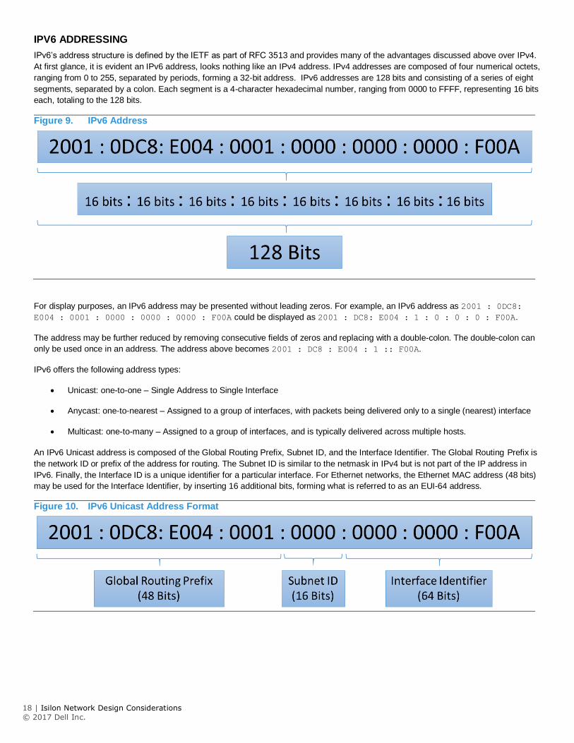
IPV6 ADDRESSING
IPv6’s address structure is defined by the IETF as part of RFC 3513 and provides many of the advantages discussed above over IPv4.
At first glance, it is evident an IPv6 address, looks nothing like an IPv4 address. IPv4 addresses are composed of four numerical octets,
ranging from 0 to 255, separated by periods, forming a 32-bit address. IPv6 addresses are 128 bits and consisting of a series of eight
segments, separated by a colon. Each segment is a 4-character hexadecimal number, ranging from 0000 to FFFF, representing 16 bits
each, totaling to the 128 bits.
Figure 9. IPv6 Address
For display purposes, an IPv6 address may be presented without leading zeros. For example, an IPv6 address as 2001 : 0DC8:
E004 : 0001 : 0000 : 0000 : 0000 : F00A could be displayed as 2001 : DC8: E004 : 1 : 0 : 0 : 0 : F00A.
The address may be further reduced by removing consecutive fields of zeros and replacing with a double-colon. The double-colon can
only be used once in an address. The address above becomes 2001 : DC8 : E004 : 1 :: F00A.
IPv6 offers the following address types:
Unicast: one-to-one – Single Address to Single Interface
Anycast: one-to-nearest – Assigned to a group of interfaces, with packets being delivered only to a single (nearest) interface
Multicast: one-to-many – Assigned to a group of interfaces, and is typically delivered across multiple hosts.
An IPv6 Unicast address is composed of the Global Routing Prefix, Subnet ID, and the Interface Identifier. The Global Routing Prefix is
the network ID or prefix of the address for routing. The Subnet ID is similar to the netmask in IPv4 but is not part of the IP address in
IPv6. Finally, the Interface ID is a unique identifier for a particular interface. For Ethernet networks, the Ethernet MAC address (48 bits)
may be used for the Interface Identifier, by inserting 16 additional bits, forming what is referred to as an EUI-64 address.
Figure 10. IPv6 Unicast Address Format
19 | Isilon Network Design Considerations
© 2017 Dell Inc.
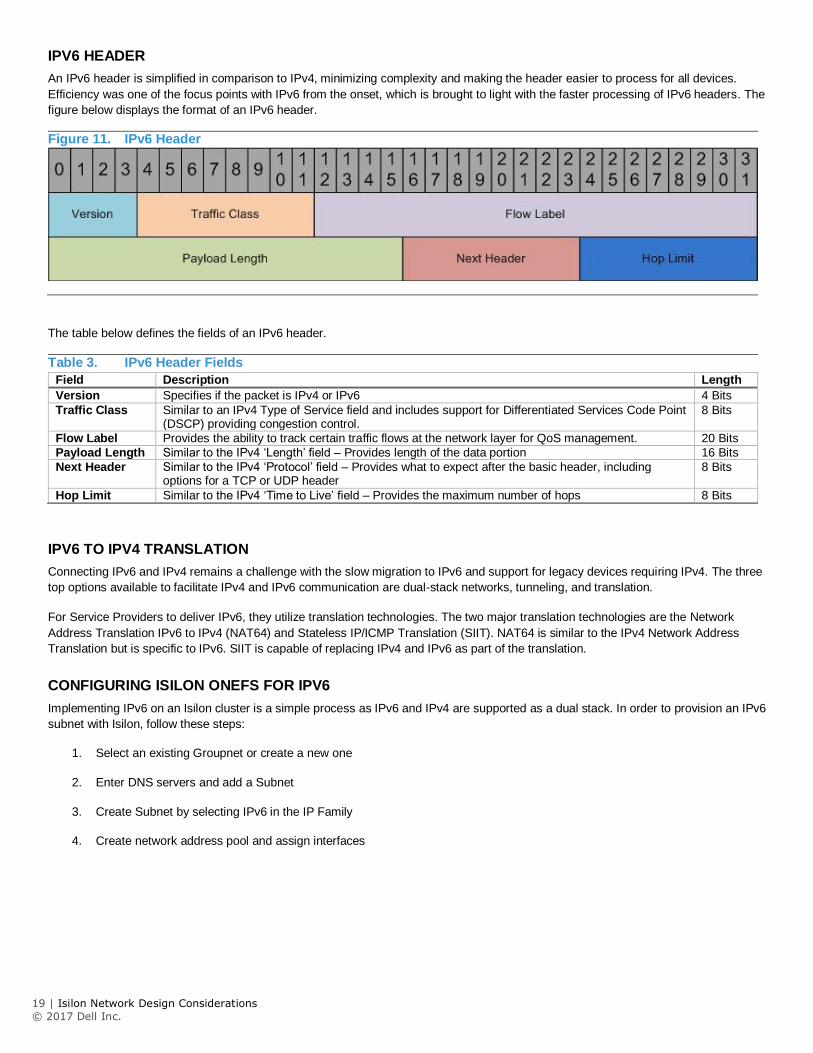
IPV6 HEADER
An IPv6 header is simplified in comparison to IPv4, minimizing complexity and making the header easier to process for all devices.
Efficiency was one of the focus points with IPv6 from the onset, which is brought to light with the faster processing of IPv6 headers. The
figure below displays the format of an IPv6 header.
Figure 11. IPv6 Header
The table below defines the fields of an IPv6 header.
Table 3. IPv6 Header Fields
Field Description Length
Version Specifies if the packet is IPv4 or IPv6 4 Bits
Traffic Class Similar to an IPv4 Type of Service field and includes support for Differentiated Services Code Point (DSCP) providing congestion control.
8 Bits
Flow Label Provides the ability to track certain traffic flows at the network layer for QoS management. 20 Bits
Payload Length Similar to the IPv4 ‘Length’ field – Provides length of the data portion 16 Bits
Next Header Similar to the IPv4 ‘Protocol’ field – Provides what to expect after the basic header, including options for a TCP or UDP header
8 Bits
Hop Limit Similar to the IPv4 ‘Time to Live’ field – Provides the maximum number of hops 8 Bits
IPV6 TO IPV4 TRANSLATION
Connecting IPv6 and IPv4 remains a challenge with the slow migration to IPv6 and support for legacy devices requiring IPv4. The three
top options available to facilitate IPv4 and IPv6 communication are dual-stack networks, tunneling, and translation.
For Service Providers to deliver IPv6, they utilize translation technologies. The two major translation technologies are the Network
Address Translation IPv6 to IPv4 (NAT64) and Stateless IP/ICMP Translation (SIIT). NAT64 is similar to the IPv4 Network Address
Translation but is specific to IPv6. SIIT is capable of replacing IPv4 and IPv6 as part of the translation.
CONFIGURING ISILON ONEFS FOR IPV6
Implementing IPv6 on an Isilon cluster is a simple process as IPv6 and IPv4 are supported as a dual stack. In order to provision an IPv6
subnet with Isilon, follow these steps:
1. Select an existing Groupnet or create a new one
2. Enter DNS servers and add a Subnet
3. Create Subnet by selecting IPv6 in the IP Family
4. Create network address pool and assign interfaces
20 | Isilon Network Design Considerations
© 2017 Dell Inc.
NETWORK TROUBLESHOOTING
This section provides steps for assessing and troubleshooting network issues with generally available utilities.
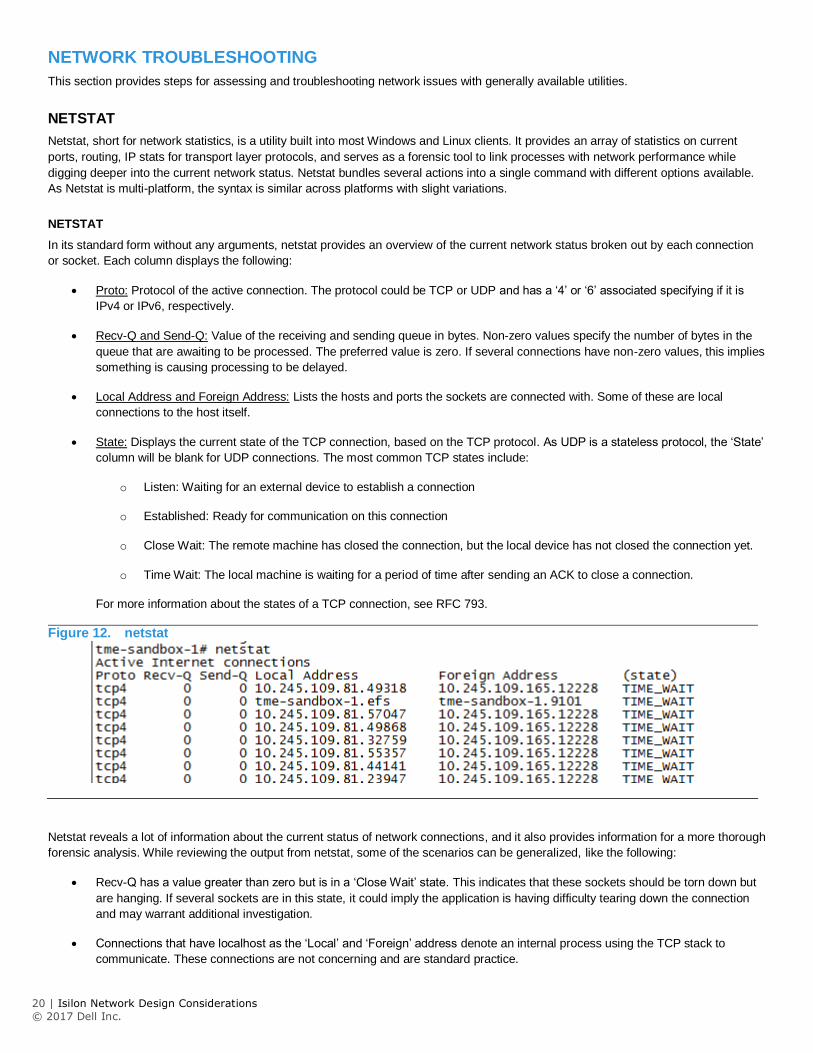
NETSTAT
Netstat, short for network statistics, is a utility built into most Windows and Linux clients. It provides an array of statistics on current
ports, routing, IP stats for transport layer protocols, and serves as a forensic tool to link processes with network performance while
digging deeper into the current network status. Netstat bundles several actions into a single command with different options available.
As Netstat is multi-platform, the syntax is similar across platforms with slight variations.
NETSTAT
In its standard form without any arguments, netstat provides an overview of the current network status broken out by each connection
or socket. Each column displays the following:
Proto: Protocol of the active connection. The protocol could be TCP or UDP and has a ‘4’ or ‘6’ associated specifying if it is
IPv4 or IPv6, respectively.
Recv-Q and Send-Q: Value of the receiving and sending queue in bytes. Non-zero values specify the number of bytes in the
queue that are awaiting to be processed. The preferred value is zero. If several connections have non-zero values, this implies
something is causing processing to be delayed.
Local Address and Foreign Address: Lists the hosts and ports the sockets are connected with. Some of these are local
connections to the host itself.
State: Displays the current state of the TCP connection, based on the TCP protocol. As UDP is a stateless protocol, the ‘State’
column will be blank for UDP connections. The most common TCP states include:
o Listen: Waiting for an external device to establish a connection
o Established: Ready for communication on this connection
o Close Wait: The remote machine has closed the connection, but the local device has not closed the connection yet.
o Time Wait: The local machine is waiting for a period of time after sending an ACK to close a connection.
For more information about the states of a TCP connection, see RFC 793.
Figure 12. netstat
Netstat reveals a lot of information about the current status of network connections, and it also provides information for a more thorough
forensic analysis. While reviewing the output from netstat, some of the scenarios can be generalized, like the following:
Recv-Q has a value greater than zero but is in a ‘Close Wait’ state. This indicates that these sockets should be torn down but
are hanging. If several sockets are in this state, it could imply the application is having difficulty tearing down the connection
and may warrant additional investigation.
Connections that have localhost as the ‘Local’ and ‘Foreign’ address denote an internal process using the TCP stack to
communicate. These connections are not concerning and are standard practice.
21 | Isilon Network Design Considerations
© 2017 Dell Inc.
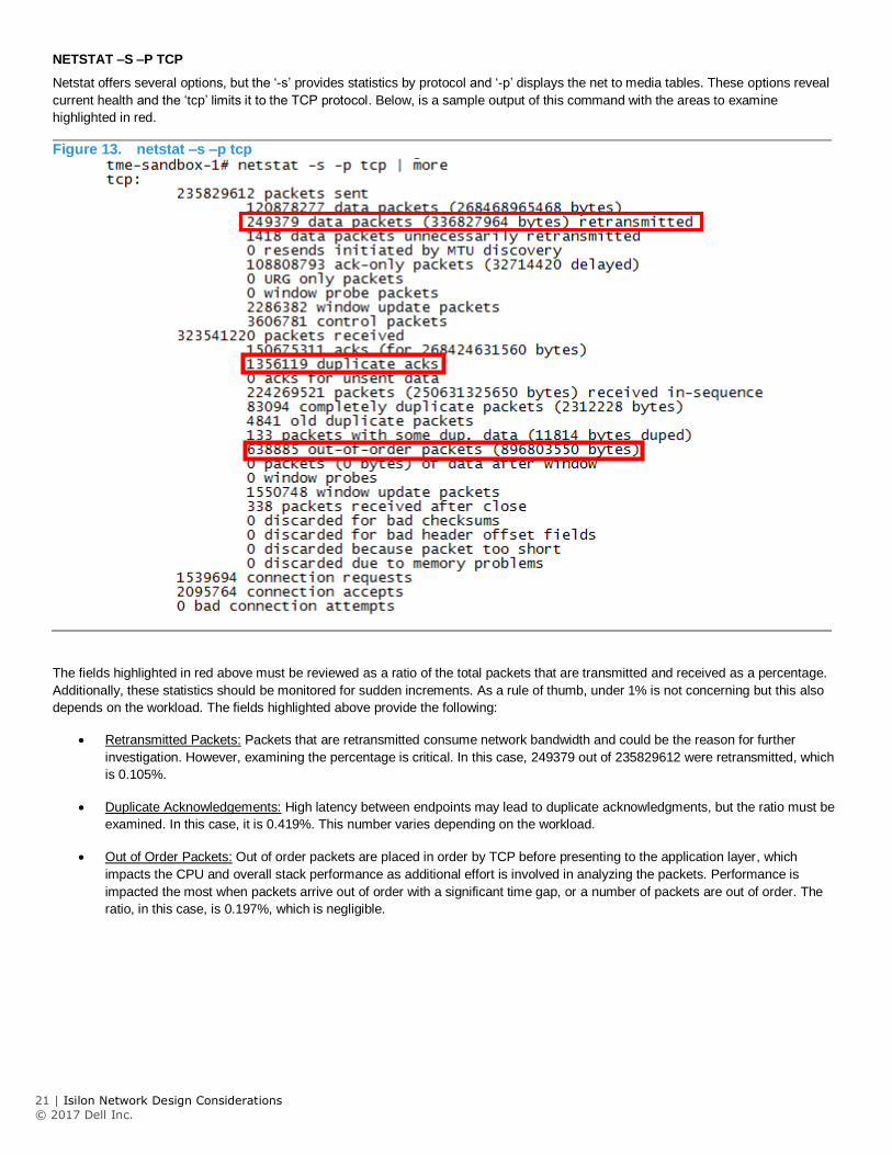
NETSTAT –S –P TCP
Netstat offers several options, but the ‘-s’ provides statistics by protocol and ‘-p’ displays the net to media tables. These options reveal
current health and the ‘tcp’ limits it to the TCP protocol. Below, is a sample output of this command with the areas to examine
highlighted in red.
Figure 13. netstat –s –p tcp
The fields highlighted in red above must be reviewed as a ratio of the total packets that are transmitted and received as a percentage.
Additionally, these statistics should be monitored for sudden increments. As a rule of thumb, under 1% is not concerning but this also
depends on the workload. The fields highlighted above provide the following:
Retransmitted Packets: Packets that are retransmitted consume network bandwidth and could be the reason for further
investigation. However, examining the percentage is critical. In this case, 249379 out of 235829612 were retransmitted, which
is 0.105%.
Duplicate Acknowledgements: High latency between endpoints may lead to duplicate acknowledgments, but the ratio must be
examined. In this case, it is 0.419%. This number varies depending on the workload.
Out of Order Packets: Out of order packets are placed in order by TCP before presenting to the application layer, which
impacts the CPU and overall stack performance as additional effort is involved in analyzing the packets. Performance is
impacted the most when packets arrive out of order with a significant time gap, or a number of packets are out of order. The
ratio, in this case, is 0.197%, which is negligible.
22 | Isilon Network Design Considerations
© 2017 Dell Inc.
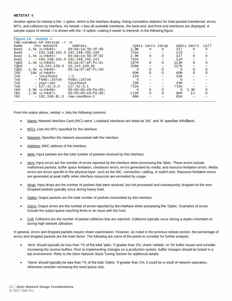
NETSTAT –I
Another option for netstat is the –i option, which is the interface display, listing cumulative statistics for total packets transferred, errors,
MTU, and collisions by interface. As netstat –i lists all available interfaces, the back-end, and front-end interfaces are displayed. A
sample output of netstat –i is shown with the –h option, making it easier to interpret, in the following figure:
Figure 14. netstat –i
From the output above, netstat –i, lists the following columns:
Name: Network Interface Card (NIC) name. Loopback interfaces are listed as ‘lo0,’ and ‘ib’ specifies InfiniBand.
MTU: Lists the MTU specified for the interface.
Network: Specifies the network associated with the interface.
Address: MAC address of the interface.
Ipkts: Input packets are the total number of packets received by this interface.
Ierrs: Input errors are the number of errors reported by the interface when processing the ‘Ipkts.' These errors include
malformed packets, buffer space limitation, checksum errors, errors generated by media, and resource limitation errors. Media
errors are errors specific to the physical layer, such as the NIC, connection, cabling, or switch port. Resource limitation errors
are generated at peak traffic when interface resources are exceeded by usage.
Idrop: Input drops are the number of packets that were received, but not processed and consequently dropped on the wire.
Dropped packets typically occur during heavy load.
Opkts: Output packets are the total number of packets transmitted by this interface
Oerrs: Output errors are the number of errors reported by the interface when processing the ‘Opkts.' Examples of errors
include the output queue reaching limits or an issue with the host.
Coll: Collisions are the number of packet collisions that are reported. Collisions typically occur during a duplex mismatch or
during high network utilization.
In general, errors and dropped packets require closer examination. However, as noted in the previous netstat section, the percentage of
errors and dropped packets are the main factor. The following are some of the points to consider for further analysis:
‘Ierrs’ should typically be less than 1% of the total ‘Ipkts.' If greater than 1%, check ‘netstat –m’ for buffer issues and consider
increasing the receive buffers. Prior to implementing changes on a production system, buffer changes should be tested in a
lab environment. Refer to the Isilon Network Stack Tuning Section for additional details.
‘Oerrs’ should typically be less than 1% of the total ‘Opkts.’ If greater than 1%, it could be a result of network saturation,
otherwise consider increasing the send queue size.
23 | Isilon Network Design Considerations
© 2017 Dell Inc.
The ratio of ‘Coll’ to ‘Opkts,' should typically be less than 10%. If greater than 10%, it could be a result of high network
utilization.
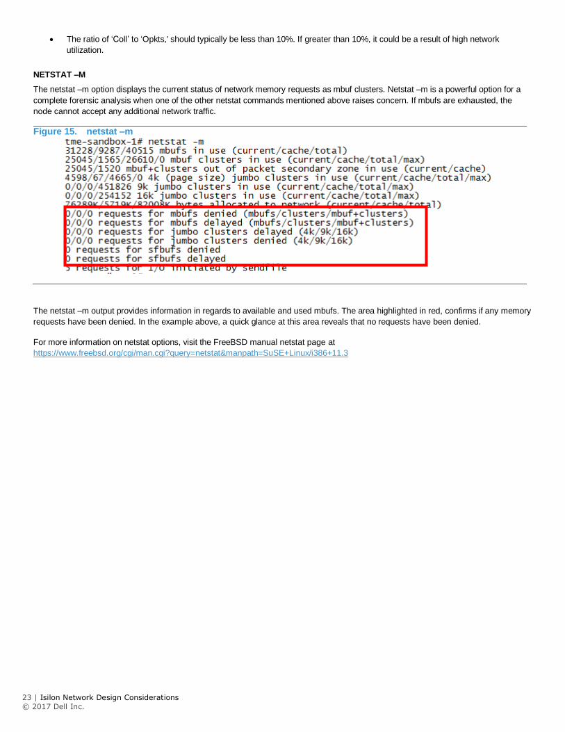
NETSTAT –M
The netstat –m option displays the current status of network memory requests as mbuf clusters. Netstat –m is a powerful option for a
complete forensic analysis when one of the other netstat commands mentioned above raises concern. If mbufs are exhausted, the
node cannot accept any additional network traffic.
Figure 15. netstat –m
The netstat –m output provides information in regards to available and used mbufs. The area highlighted in red, confirms if any memory
requests have been denied. In the example above, a quick glance at this area reveals that no requests have been denied.
For more information on netstat options, visit the FreeBSD manual netstat page at
https://www.freebsd.org/cgi/man.cgi?query=netstat&manpath=SuSE+Linux/i386+11.3
24 | Isilon Network Design Considerations
© 2017 Dell Inc.
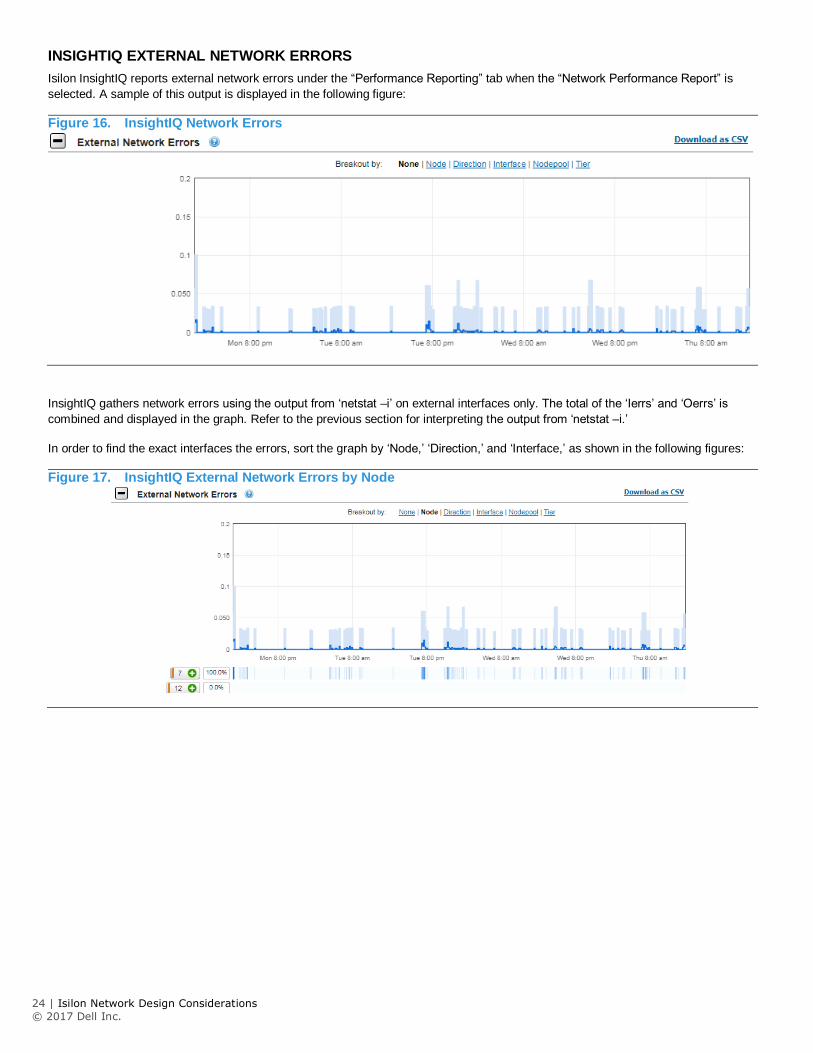
INSIGHTIQ EXTERNAL NETWORK ERRORS
Isilon InsightIQ reports external network errors under the “Performance Reporting” tab when the “Network Performance Report” is
selected. A sample of this output is displayed in the following figure:
Figure 16. InsightIQ Network Errors
InsightIQ gathers network errors using the output from ‘netstat –i’ on external interfaces only. The total of the ‘Ierrs’ and ‘Oerrs’ is
combined and displayed in the graph. Refer to the previous section for interpreting the output from ‘netstat –i.’
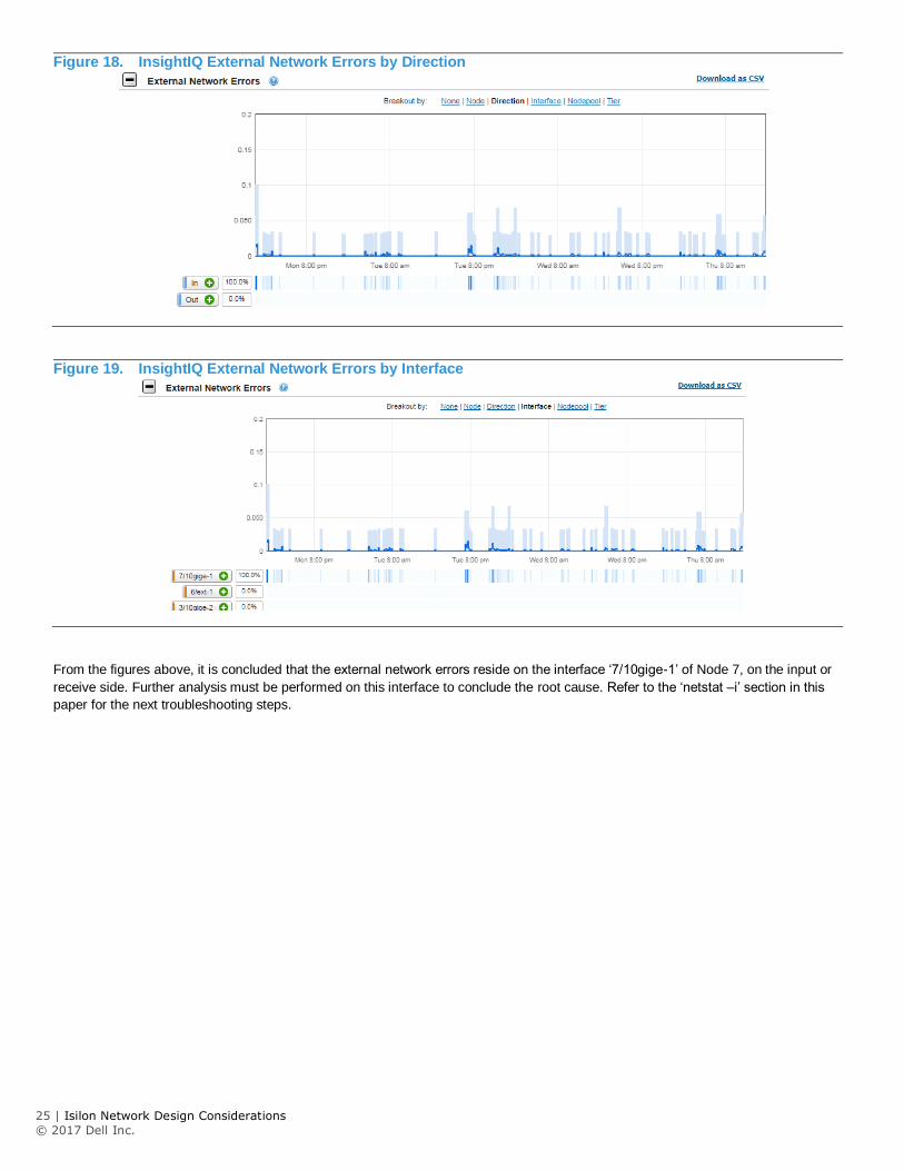
In order to find the exact interfaces the errors, sort the graph by ‘Node,’ ‘Direction,’ and ‘Interface,’ as shown in the following figures:
Figure 17. InsightIQ External Network Errors by Node
25 | Isilon Network Design Considerations
© 2017 Dell Inc.
Figure 18. InsightIQ External Network Errors by Direction
Figure 19. InsightIQ External Network Errors by Interface
From the figures above, it is concluded that the external network errors reside on the interface ‘7/10gige-1’ of Node 7, on the input or
receive side. Further analysis must be performed on this interface to conclude the root cause. Refer to the ‘netstat –i’ section in this
paper for the next troubleshooting steps.
26 | Isilon Network Design Considerations
© 2017 Dell Inc.
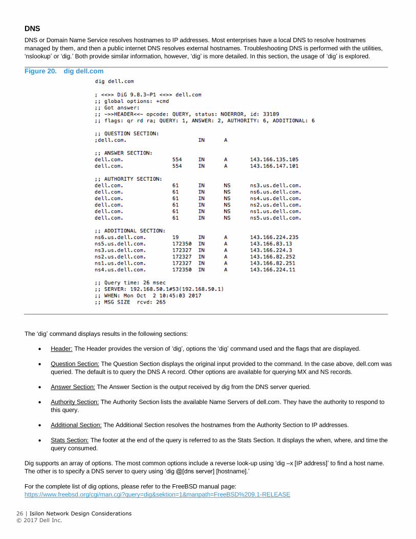
DNS
DNS or Domain Name Service resolves hostnames to IP addresses. Most enterprises have a local DNS to resolve hostnames
managed by them, and then a public internet DNS resolves external hostnames. Troubleshooting DNS is performed with the utilities,
‘nslookup’ or ‘dig.’ Both provide similar information, however, ‘dig’ is more detailed. In this section, the usage of ‘dig’ is explored.
Figure 20. dig dell.com
The ‘dig’ command displays results in the following sections:
Header: The Header provides the version of ‘dig’, options the ‘dig’ command used and the flags that are displayed.
Question Section: The Question Section displays the original input provided to the command. In the case above, dell.com was
queried. The default is to query the DNS A record. Other options are available for querying MX and NS records.
Answer Section: The Answer Section is the output received by dig from the DNS server queried.
Authority Section: The Authority Section lists the available Name Servers of dell.com. They have the authority to respond to
this query.
Additional Section: The Additional Section resolves the hostnames from the Authority Section to IP addresses.
Stats Section: The footer at the end of the query is referred to as the Stats Section. It displays the when, where, and time the
query consumed.
Dig supports an array of options. The most common options include a reverse look-up using ‘dig –x [IP address]’ to find a host name.
The other is to specify a DNS server to query using ‘dig @[dns server] [hostname].’
For the complete list of dig options, please refer to the FreeBSD manual page:
https://www.freebsd.org/cgi/man.cgi?query=dig&sektion=1&manpath=FreeBSD%209.1-RELEASE
27 | Isilon Network Design Considerations
© 2017 Dell Inc.
NETWORKING TOOLS
The following tools help troubleshooting or lab configurations for testing:
Brocade Virtual Router: http://www.brocade.com/en/products-services/software-networking/network-functions-virtualization/vrouter.html
REFERENCES
Cisco Nexus 5000 Series Configuration Guide:
http://www.cisco.com/c/en/us/td/docs/switches/datacenter/nexus5000/sw/configuration/guide/cli/CLIConfigurationGuide/QoS.html#pgfId
-1138522
Cisco Catalyst 6500 Best Practices:
http://www.cisco.com/c/en/us/td/docs/switches/lan/catalyst6500/ios/12-2SX/best/practices/recommendations.html#wp1039880
Brocade Switching Configuration Guide:
http://www.brocade.com/content/html/en/configuration-guide/NI_05800a_SWITCHING/GUID-8B890954-65A7-41DA-8E10-
7A88DFDA687C.html
Arista Product Documentation:
https://www.arista.com/en/support/product-documentation
Configuration of Jumbo MTU on Nexus 5000 and 7000 Series:
http://www.cisco.com/c/en/us/support/docs/switches/nexus-5000-series-switches/112080-config-mtu-nexus.html
IEEE Standards
https://standards.ieee.org/findstds/standard/802.1AX-2008.html
SMBv3 Multi-Channel:
https://blogs.technet.microsoft.com/josebda/2012/06/28/the-basics-of-smb-multichannel-a-feature-of-windows-server-2012-and-smb-3-
0/
RFCs:
http://www.faqs.org/rfcs/rfc1812.html
http://www.faqs.org/rfcs/rfc1122.html
http://www.faqs.org/rfcs/rfc1123.html
https://tools.ietf.org/html/rfc3971 https://tools.ietf.org/html/rfc792 https://tools.ietf.org/html/rfc3513

28 | Isilon Network Design Considerations
© 2017 Dell Inc.
Learn more about Dell EMC Isilon
solutions Contact a Dell EMC Expert
© 2017 Dell Inc. or its subsidiaries. All Rights Reserved. Dell, EMC and other trademarks are trademarks of Dell Inc. or its subsidiaries. Other trademarks may be trademarks of their respective
owners. Reference Number: H16463