Embed Size (px)
Citation preview

Disclosure to Promote the Right To Information
Whereas the Parliament of India has set out to provide a practical regime of right to information for citizens to secure access to information under the control of public authorities, in order to promote transparency and accountability in the working of every public authority, and whereas the attached publication of the Bureau of Indian Standards is of particular interest to the public, particularly disadvantaged communities and those engaged in the pursuit of education and knowledge, the attached public safety standard is made available to promote the timely dissemination of this information in an accurate manner to the public.
इंटरनेट मानक
“!ान $ एक न' भारत का +नम-ण”Satyanarayan Gangaram Pitroda
“Invent a New India Using Knowledge”
“प0रा1 को छोड न' 5 तरफ”Jawaharlal Nehru
“Step Out From the Old to the New”
“जान1 का अ+धकार, जी1 का अ+धकार”Mazdoor Kisan Shakti Sangathan
“The Right to Information, The Right to Live”
“!ान एक ऐसा खजाना > जो कभी च0राया नहB जा सकता है”Bhartṛhari—Nītiśatakam
“Knowledge is such a treasure which cannot be stolen”
“Invent a New India Using Knowledge”
है”ह”ह
IS/IEC 60079-19 (2006): Explosive atmospheres, Part 19:Repair, overhaul and reclaation [ETD 22: ElectricalApparatus for Explosive Atmosphere]

July 2008
ISflEC 60079-19 : 2006
'J.fNrfla 'iFFh
~~
Indian Standard
EXPLOSIVE ATMOSPHERESPART 19 REPAIR, OVERHAUL AND RECLAMATION
ICS 29.260.20
e SIS 2008
BUREAU OF INDIAN STANDARDSMANAK SHAVAN , 9 SAHADUR SHAH ZAFAR MARG
NEW DELHI 110002
Price Group 14
Electrical Apparatus for Explosive Atmospheres Sectional Committee, ETD 22
NATIONAL FOREWORD
This Indian Standard (Part 19) which is identical with IEC 60079-19 : 2006 'Explosive atmospheresPart 19: Equipment repair, overhaul and reclamation' issued by the Internat ional ElectrotechnicalCommission (IEC) was adopted by the Bureau of Indian Standards on the recommendation of theElectricalApparatusfor ExplosiveAtmospheresSectional Committee and approvalof the ElectrotechnicalDivision Council.
The text of IEC Standard has been approved as suitable for publication as an Indian Standardwithout deviations. Certain conventions are, however, not identical to those used in Indian Standards,Attention is particularly drawn to the following:
a) Wherever the words 'International Standard' appear referring to this standard, they shouldbe read as 'Indian Standard',
b) Comma (,) has been used as a decimal marker while in Indian Standards , the currentpractice is to use a point (.) as the decimal marker.
In this adopted standard, referencesappear to certain International Standards for which Indian Standardsalso exist. The corresponding Indian Standards, which are to be substituted in their respective placesare listed below along with their degree of equivalence for the editions indicated:
International Standard
IEC 60079 (all parts) Explosiveatmospheres
IEC 60085 : 1984 Thermalevaluation and classification ofelectrical insulation
IEC 60529 : 1989 Degrees ofprotection provided byenclosures( IP Codes)
ISO 4526 : 1984 Metalliccoatings- Electroplatedcoatings of nickelfor engineering purposes
ISO6158 : 1984 Metallic coatings- Electrodeposited coatings ofchromium for engineeringpurposes
ISO 9000 2005 Qualitymanagement and systemsFundamentals and vocabulary
Corresponding Indian Standard
IS/IEC 60079 (all parts) Explosiveatmospheres
IS 1271 : 1985 Thermal evaluation andclassification of electrical insulation (firstrevision)
IS 12063 : 1987 Classif ication of degreesof protection provided by enclosures ofelectrical equipment
IS 12393 : 1988 Electroplated coatings ofnickel
IS 1337 : 1993 Electroplated coatings ofhard chromium for engineering purposes(third revision)
IS/ISO 9000 : 2005 Quality managementsystems - Fundamentals and vocabulary(third revision)
Degree ofEquivalence
Identical
TechnicallyEquivalent
do
do
do
Identical
The technical committee responsible for the preparation of this standard has reviewed the provisions ofthe follOWing International Standards referred to in this adopted standard and has decided that they areacceptable for use in conjunction with this standard:
International Standard
IEC 61241 ·0
Title
Electr ical apparatus for use in the presence of combustible dust Part 0 : General requirements
(Continued on third cover)
ISIIEC 60079-19: 2006
Indian Standard
EXPLOSIVE ATMOSPHERESPART 19 REPAIR, OVERHAUL AND RECLAMATION
1 Scope
Th is part of IEC 60079
gives Instructions, pr incipally of a technica l nature , on the repair , overhaul , rectamenenand modification of a certified equipment des igned for use in explos ive atmospheres ,
is not app licable to ma intenance, other than when repa ir lind overhaul cannot bedisassociated from maintenance, neithe r does it give adv ice on cable entry sys tems wh ichmay require renewa l when the equ ipment is re- installed ;
is not appl icable to type of protection 'rn',
assumes that good engineering practices are adopted throughout
NOTE Much of the content of th is standard is concerned with the repair and overhaul of eleelnca l rotatingINIchines . This is not because they are the most import ant Items of e.plosion-protected equipment but ratherbecause they are often ms jor ite ms of repai rable cap ital equ ipment on whoch. whatever typo of protectIon"involved. sufficient commonsllty of construel ion e.osts as to make pou,ble more detetled InstruellOns fo, the irrepsir. overhaul . reclamation or modification .
2 Nonnative references
The following referenced documents are ind ispensable for the application of th is documel11For dated references , only the edition Cited applies . For undated references, the latest editionof the referenced document ( including any amendments) applies
IEC 60079 (all parts) , Explos ive atmospheres
IEC 60085, Electrical insulation - Thermal classification
IEC 60529, Degrees of protection provided by enclosures (IP Code)
IEC 61241-0, Electrical apparatus for use in fhe presene,e of combustible dust - Part 0General requirements
IEC 61241-2, Electrical apparatus for use in the presence of combustible dusl - Part 2 Teslmethods
ISO 4526 , Metallic coatings - Electroplated coafings of nickel for engineering purposes
ISO 6158, Metallic castings - Electrodeposited coatings of cnromtum for eng;neenngpurposas
ISO 9000, Quality management and systems - Fundamentals and vocabUlary
ISIIEC 6007~19: 2006
3 Terms and definitions
For the purposes of this document, the following terms and definitions apply.
3.1serviceable conditioncondition which permits a replacement or reclaimed component part to be used withoutprejud ice to the performance or explosion protect ion aspects of the equ ipment, with dueregard to the certification requirements as appl icable, in wh ich such a component part is used
3.2repairact ion to restore faulty equipment to its fully serviceable cond it ion and in compliance with therelevant standard
NOTE The relevant standard means the standard to which the equipment was or iginally designed .
3.3overhaulaction to restore to a fUlly serviceable condition equipment wh ich has been in use or instorage for a period of time but wh ich is not faulty
3.4maintenancerout ine act ions taken to preserve the fully serviceable condition of the installed equipment(see Clause 1)
3.5component partan mervrs ible Item
NOTE The usembly of such items may form equipment.
3.8reclamationmeans of repair involving , for example , the removal or addit ion of material to reclaimcomponent parts wh ich have sustained damage, in order to restore such parts to aserviceable cond ition in accordance With the relevant standard
NOTE The relevant standard means the standard to which the individual parts were oroginally manufactured .
3.7modificationchange to the design of the equipment which affects material, fit , form or function
3.8manufacturermaker of the equ ipment (who may also be the supplier, the Importer or the agent) 10 whosename usually the certification , whe re appropriate. of the equipment was originally reg istered
3.9useruser of the equ ipment
2
ISIIEC eoo~19: 2006
3.10repa Ir facilityfacil ity providing a service that consists of repairs. overhauls, or reclamations 0' ellploS lonprotected equipment who may be the manutacturer, the user or a third party (repair agency)
3.11certificationcertif ication lead ing to the Issue of a certificate 0' conformity which refers prtmarrly toassessments of equ ipment carried out by a recognized testing authorrty
This standard may also apply to equ ipment certified by other certification authorrtles, or toequ ipment wh ich has been self-certified by manufacturers or users as complying withrecogn ized standards .
3.12certificate referencesa certificate reference number may refer to a single design or a range of equ ipment 0' similardesign
3.13symbo'''X''the symbol "X" is used to denote specia l conditions 0' sa'e use . The certification documentsneed to be stud ied betore such equ ipment IS installed, repa ired , overhauled, reclaimed ormod if ied .
3.1<© windingprocess by wh ich a winding is totally or part ially replaced by another, the characterist ics andproperties 0' wh ich are at least as good as those 0' the or iginal
3.15type of protection "d"type of protection in which parts which can ignite an explosive atmosphere are placed In anenclosure which can withstand the pressure developed during an explosron of an exploSIvemixture and which prevents the transmission 0' the explosion to the explosIve atmospheresurrounding the enclosure
3.16type of protection "I"circu it In which no spark or any thermal effect produced In the test cond itions pres Crtbed Inthe relevant standard(s) ~whlch Include normal operation and specl'lc fault condition) IS
capable of causing IgnitIon of a given explosive atmosphere
3.17type of protection "p"type of protect ion by wh ich the entry 0' a surround ing atmosphere into the enclosure of theelectrical equ ipment is prevented by maintaining, Inside the said enclosure, a protective gasat a higher pressure than that of the surrounding atmosphere. The overpressure IS maintainedeither With or without 8 continuous flow 0' the protective gas
3.18type of protection "e"type 0' protection by wh ich measures are appl ied so as to prevent, with a higher degree ofsecurity, the possibility of excess ive temperatures and the occurrence of arcs or sparks in theinterior and on the external parts of the electrical equipment which would not produce them innormal service
3
ISilEe 60079-19: 2006
J .1itype of protection "n"type of pretecticn appl ied to the electrical equ ipment such that , in norma l operation , it is notcapable of igniti ng the surrounding exp los ive atmosphere and that a fau lt capab le of caus ingignition is not likely to occur
3.20type of protection UtO"type of protection for explosive dust atmospheres where electrical equ ipment is provided withan enclosure providing dust ingress protection and a means to limit surface temperatures
3.21type of protection "pO"type of protection reliant upon the enc losure being subjected to a continuous pressure,according to lEe 61241-2, from a supply of uncontaminated air or other non-flammable gaswhile electricity is connected to the enc losure
4 General
4.1 General principles
This clause covers those aspects of repa ir , overhaul , reclamat ion and mod ification wh ich arecommon to all explos ion-protected equ ipme nt . Subsequent cla uses prov ide inst ructi ons forthe addit ional requ irements relevant to spec ific types of protection . When equipmentIncorporates more than one type of protection , reference sha ll be made to the appropriateclauses
NOTE 1 Addit iona l req uirements for types of protection ·0· and "q" have no t been de fined .
Ass uming that repairs and ove rhau ls are carr ied out us ing good eng ineer ing pract ices , then
a) If manufacturers ' specif ied parts or parts as r.pecified in the certification documentationare used In a repair or overhau l, the equ ipment is presumed to be In conformity w ith thecertificate:
b) If repa irs or mod if ications are carried out on the equ ipment spec if ically as deta iled in thecert ification documents , the equipment should still conform with the cert if icate.
In circumstances where the cernncanon documents are not ava ilable, then the repair oroverhaul shall be carried out on the equipment In accordance with this standard and otherrelevant standard(s) . The steps taken to obtain the certification documents shall be recordedIn the repair faCIlity records (see 4 4 1 5 3)
If othe r repa ir or mod ification techniques are used wh ich are not in accordance with thisstandard , then It will be necessary to ascertain, from the manu facturers , and/or thecert if ication authonty, the SUitability of the equipment for continued use in an explosiveatmosphere
NOTE 2 Repair of equ ipment which has no marking plate should be avo ided .
4.2 Statutory requirements
4.2.1 Rep.ir facility
The repair faci lity sha ll be awa re of any specific requ irements in relevant national leg islationwhich may govern the repair or overhaul operation .
4
ISIIEC 6007~19: 2006
4.2.2 U.er
The equipment user should be aware of any relevant legislation should he wish to undertakethe repair or overhaul of equ ipment himself In addition . he should be aware of any changes In
respons ibi lity for health and safety, shou ld refurbishment and/or re-Installatlon be camed outby a th ird party.
4.3 Instructions for the user
4.3 .1 Certificates and document.
The equipment design cert if icate and other related documents (see 44.1.5 .1) should beobtained as part of the or ig ina l purchase contract
4.3.2 Record. and work Instruction.
All relevant documentation that IS ava ilab le sha ll be obta ined as part of the origlOal purc hasecontract Records of any previous repa irs . overhauls or modifications shall be kept by the use rand made available to the repairer
NOTE It will be In the Interests of the user thet the repeirer I.nollf'ed. whenever ponib le, of the feull end /o rneture of the _rk to be done.
Special requirements stipulated in the user's specifications , and which are supplementary tothe various standards, e.g . enhanced ingress protection , shall be brought to the attenlion ofthe repairer.
The user shall inform the repairer of any statutory requirement for compliance Withcertification (see note in the introduction)
4.3 .3 Re-Inatallatlon of repaired equipment
Before the repaired equipment is re-commiss ioned, cable/conduit entry systems shall bechecked to ensure that they are undamaged and are appropnate to the equipment type ofprotection . Recommendations may be found in the wIring systems clause of lEe 60079·14
4.3.4 Repair facllltiea
The user shall ascertain that the repair faCIlity concerned can demonstrate compliance Withthe relevant st ipulaticns of this standard .
4.4 Inatructlons for the repair facility
4.4.1 Repair and overhaul
4.4.1.1 General
Repair facilities shall operate a auallty Management System that meets with the reqUirementsof the ISO 9000 series of standards.
The repa ir facility shall appoint a person ('Respons ible Person') with the required competency(see Annex B), within the management organ ization , to accept responsibil ity snd authOrity forensuring that the overhauled/repa ired equ ipment complies With the certification status agreedwith the user. The person so appointed shall have a working knowledge of the app ropnateexplosion protection standards and an understanding of th is standard.
5
ISIIEC 60079-19: 2006
The repa ir fac ility must have adequate repa ir and over haul fac ili t ies as well as the appropriateequipme nt necessary and tra ined Operat ives with the req uired competency (see Annex B)and authority to carry out the act iv ities , tak ing into account the spec if ic type of protection .
The repair facility shall conduct an assessment of the status of the equipment to be repa ired ,agree with the user the expected certification status of the equipment after repair and thescope of work to be done . Th is should include the om ission of any tests mentioned within th isdocument that the user could reasonably assume to be included. The assessment sha ll bedocumented and shall address the relevant cla uses of the appropriate equ ipment standardand this standard and be included in the job report to the user. Such assessments shall beconducted by the Responsible Person (supported by appropriate Operatives) . TheResponsible Person shall only conduct assessments with the explosion protection techniquesfor which he has demonstrated his competence.
The repair facility shall include procedures and systems to carry out overhaul/repa ir work atsites external to the repair facility, where appropriate .
4.4 .1.2 Certification and standards
The repairer's attention is directed to the need to be informed of , and to comply with, therelevant explos ion-protection standards and certification req uirements applicable to theequipment to be repaired or overhauled .
4.4.1.3 Competency
The repa irer of the equ ipment sha ll ensure that those operatives directly concerned with therepa ir and/or overnau l of the cert if ied equ ipment are trained , experienced, skilled ,knowledgeable and/or supervised on th is type of work.
Training and competency assessments are specified in Annex B.
Appropriate tra ining and assessment shall te undertaken from time to time at intervalsdepending on the frequency of utilization of the technique or sk ill anlj change of standards orregulations The interval should normally not exceed three years .
4.4.1.4 Te.tlng
Should it prove Impracticable to carry out certa in tests , e.g ., a component of a completeequipment taken off site for repair such as a rotor of a rotat ing machine, the repa irer shall,before putting the repa ired equ ipment back Into service, ascerta in from the user ormanufacturer the consequences of omitting such tests .
NOTE In.ome countries . legel consequences nlIIy depend upon the extent to which the a1rrying out or not ofcertaIn acltOn. or te.t. IS practIcable .
4.4 .1.5 Document8tlon
4.4.1 .5.1 General
The repair fac ility should seek to obtain all necessary information/data from the manufactureror user for the repair and/or overhaul of the equ ipment. Th is may include informati on relatingto previous repa irs . overhauls or mod ifications . He should also have ava ilable and refer to therelevant explosion-protection standard.
6
ISIIEC 6007~19: 2006
The data available for the repair and/or overhaul should Include but need not be liml l ed 10 ,
details of the
techn ical specification ,
drawings,
exp los ion protection performance and cond it ions of use ,
dismantling and assembly instructions ,
certificate limitat ions (special conditions for safe use) , where specified ,
marking (including certification marking).
recommended methods of repair/overhaul for the equipment,
list of spare parts.
The informati on may be subject to amendments inc luding those re lat ive to certmcat ron
NOTE 1 II is nol reasonably practicable to assume that adequate Inlormalton is . or can be . so WIdely cltcul.tedthat it is alW1lys available where and when it IS needed Sources 01 adequate Inl o rmalion are use rs . man ufacturersor certifying authorities ,
NOTE 2 As from lEe 60079-0 (Edition 04). manufacturers are reqUIred to give Instructions Including repalt
The repai r fac ility shall ma inta in controlled cop ies of any relevant exptosron protect ionstandards with wh ich repaired/overhauled equipment IS cla imed to comply
4.4.1.5.2 Job report to the user
At the complet ion of the work , job reports shall be submitted to the user (see 432)containing, at least , the follOWing
details of fault detected ;
full details of repa ir and overhaul ,
list of replaced or recla imed parts ,
results of all checks and tests (In sufficient detail to be useful if required by the nextrepairer, see 4 ,3 2) ;
summary of previous history of the repaired product Including Information as gatheredunder 4.3 .2;
copy of the user contract or order.
The job reports of repa irs/overhauls shall be retamed for a period of t ime as agreed With Iheuser . Retained information shall be adequately controlled to ensure correct retrieva l
4.4.1 .5 .3 Repair facility records
The following records shall be retamed by the repair faCIlity
current and past cop ies of relevant Techn ical Standards :
cert if ication of Facility Quality Standard including
1) details of Repair provider's Quality Assessment Scheme ,
2) test instrument calibration ,
3) competency and training records of personnel ;
4) purchasing control system;
5) customer compla ints system.
7
ISIIEC 6007~19: 2006
6) mternal and, where appropriate , external audit documentation ;
7) management rev iew;
8) process control procedures;
9) register of manufacturer's draw ings ;
- Job records including :
1) the steps taken to obta in the cert ification documents;
2) mechanical inspection record for comp liance with relevant standards;
3) defect identi fication;
4) electrical test records before and after repa ir includ ing traceabi lity of instruments usedand pass/fail criter ia;
5) certificates of conformity for replacement components ;
6) recovery procedure for repa ired components ;
7) record of mechanical inspecti on during assembly and upon completion;
8) record of work undertaken by the repair facility .
The record of the recovery procedure for repaired components should, at least, identify thefollowmg:
a) a deta iled justification for the work carried out;
b) var ious options considered (e.g., weld ing, metal spraying);
c) technical parameters, e.g., bond strength;
d) the reasons for selecting the chosen techn ique ;
e) consumables used and method of storage;
f) base mater ia l;
g) manufacturers ' instructions cons idered ;
h) procedure util ized ;
I) Ident ity and competency of the operator;
I) inspection procedure used , e.g, ultra -sonic, dye-penetration, X-ray;
k) maintenance and calibration details of automatic systems .
These records shall be retained for a per iod of at least ten years or as agreed with the user.
•.4.1 .6 Spare parts
4.4 .1.6 .1 Genera'
It is preferable to obtain new parts from the manufacturer, and the repa irer shall ensure thatonly appropriate spare parts are used in the repa ir or overhaul of certified equipment.Depend ing on the nature of the equ ipment, these spare parts may be identified by themanufacturer, the equ ipment standard or the relevant certificat ion documentation.
4.•.1.6.2 Sealed parts
Parts , which are required by the equ ipment specification and cert ificate documents to besealed . shall be replaced only by the particular spare part(s) detailed in the parts list.
8

ISilEe 60079-19: 2006
NOTE [)evic;.. Incorporatad In equl~nt to Indicate Interter. nee by th ird partiea (e g . ucunty ...1,) .. do51lnetItom thoa. required in the certification documenta . ar. not Intande d to fa ll wftl\ln the aeope ot thlt .ubelauaa
..... .1.7 Identification of repaired equipment
The equipment shall be marked to identify the repair or overhaul and the repairer's IdentItyThe marking for the repa ired equipment IS given in Annex A.
Marking may be provided on a separate label It may be necessary to amend or remove orsupplement the label in certain circumstances as follows
a) If after repair, overhaul or modification , an equipment IS changed such that It no longerconforms with the standard and cernncate (see 3 11) . the certmeatrcn label shall beremoved unless a supplementary certificate has been obta ined
b) If the equ ipment is changed dur ing repair or overhaul so that It st ill complies With therestrictions imposed by this standard and the explosion protection standards to which Itwas manufactured , but does not necessarily comply with the certificate , the certificationlabel should not normally be removed and the repair symbol "R" shall be written WIthin aninverted triangle (see Annex A) . .
c) Where the standards to which the previously certified equipment was manufactured are notknown, the requirements of th is standard and the current edit ion of the relevant axptcsrcnprotection standards shall apply. An assessment, by a person competent in assessln9explosion protected equipment, shall be conducted to veflfy compliance With the relevantlevel of safety prior to release of the equipment by the repa irer .
......2 Reclamations
..... .2.1 General
Reclamations not affecting the exploslon protection are not the subject of thiS subclauseSuch parts should be reclaimed using good engineering practices
Where the repair process involves reclamation work, then , In addition to the requirements of4.4 .1 for repa irs and overhauls , the requ irements of 44 .2 also apply .
......2.2 Excluslona
Some component parts are considered not to be reclaimable and are therefore excluded fromthe scope of this standard, such as:
- component parts made from the follOWing materials : glass, plastics, or any material that ISnot dimens ionally stable;
- fasteners;
- component parts , e g., some encapsulated assemblies, wh ich have been stated by themanufacturer to .be not SUbject to repa ir
...... 2.3 Requirement•
...... 2.3.1 General
Any reclamation shall be- carned out by competent personnel, sk illed In the process to beemployed and us ing good engineering practices (see Annex B) Operators of rectamaucntechniques , e.g . weld ing, metal spraying , shall be required to undertake a practical skill test In
the technique before being permitted to utilize the technique for the flfst time and every threeyears thereafter. If the operator has not used the technique in the previous SIX months . heshall undertake are-test.
9

ISIIEC 60079-19: 2006
If any proprietary process is used , the instructi ons of the originator of such a process shouldbe followed .
All reclamation shall be properly documented and records reta ined . Such records include:
- Ident if ication of the component part ;
- method of reclamation ;
detail of any dimensions which differ from those in relevant cert ification documents or theang ina l dimensions of the component part;
drawing showing reclamation details incl uding material removed and replaced ;
- date ;
- name of the organ ization carrying out the rec lamation .
If the reclamation is carried out other than by the user, the user shall be provided with a copyof the record .
A reclamation procedure which would result in dimensions affecting explos ion-protectionintegnty being different from those given in relevant cert if ication documents may bepermissible if such changed dimensions st ill meet the requirements of the restr ict ionsImposed by this standard and the explos ion protect ion standards to wh ich It wasmanufactured. The certificat ion label should not be removed and the repa ir symbol "R" shallbe wntten with in an inverted triangle. Where the standards to wh ich the previously certifiedequipment was manufactured are not known , the requ irements of this standard and thecurrent edition of the relevant explosion protection standard shall apply. An assessment, by aperson competent in assessing explosion protected equipment shall be conducted to verifycompliance with the relevant level of safety prior to release of the equipment by the repairer.
In the event of any uncerta inty regard ing the perm iss ib il ity, from an explos ion-protectionsafety point of view, of an intended reclamation procedure. the advice of the manufacturer orcertifying authority shou ld be sought It may als o be necessary to carry out tests to verify thatthe reclamation procedure is acceptable.
4.4 .2 .3 .2 Responsibilities
If reclamations are contracted out by the repair facil ity to a special ized industry. such recla mations shall be the respons ibility of the repair facility .
4.4.2.4 Reclamation procedures
4.4.2 .4.1 General
The follOWing outlines some of the reclamation procedures which may be appl icable toexptcsrcn-protected equipment
It should be recogn ized that not all procedures are applicable to all types of protection .Deta iled Instructions are given in the appropriate clauses of th is standard.
10
ISIIEC 60079-19: 2006
Metal removal shall be min imized and be Just suttrcient to remove the defect requiring repa uand provide the minimum coating thickness recommended for the technique used Industr ygUida nce wou ld suggest that the removal of up to 2 % of metal th ickness for me tal sprayingand up to 20 % for welding will not be sign ifica ntly detrimental to the strength of thecomponent Remova l of a greater thickness of material shall only be earned out after dueconsultation with the manufacturer or by ca lcu lat ion where the manufacturer IS no longerava ilab le
On completion of the reclamation , the repa irer sha ll satisfy himself that the equ ipment IS In afully serviceable condition and compiles with the standardts) for the type of protectron Suchcompliance sha ll be recorded by the repair tac ihty and retained In the Jab flies
4.4.2.4.2 Metal spraying
Th is method sha ll be used only when the extent of the wear or damage , plus the machiningnecessary to prepare the component part for reclamation , does not weaken the part beyondsafe limits . A sprayed metal Inlay, whilst adding some stiffness, should not be taken Intoaccount when strength IS considered . Indeed , the machining process pnor to the applicationof meta l spray may Int roduce stress raiser s wh ich may further weaken the component
Meta l spraying IS not recommended fo r some high- speed and large-diam eter app lications , It ISon ly acceptab le where the matena ls are meta llurgically compatible and the parent base meta lis free from defects
4.4.2 .4.3 Electroplating
Electroplating is an acceptable procedure provided that the part is not weakened beyond safelimi ts. Deta iled procedures for chromium and nickel plating are given In ISO 6 158 andISO 4526, respect ive ly .
4.4.2.4.4 Sleeving
This method shall be used only when the extent of the wear and damage , p lus the machiningnecessary to prepare the part for reclamation , does not weaken the part beyond safe limitsA sleeve, whilst adding some snrtness. shou ld not be taken Into account when strength IS
considered .
4.4.2.4.5 Brazing and weld ing
Reclamation by braz ing or welding shall be consrdered only If the technique employedens ures the correct penetration and tusron of braze or weld With parent metal . result ing In
adequate remforcement, the prevention of distortion, the relief of stresses and the absence ofblow-holes It should be recognized that braZing and welding raise the temperature of thecomponent to a high level and may cause fatigue cracks to propagate
The following welding techn iques are recognised by th is standard.
MMA:
MIG:
TIG:
Sub-Arc :
Hot wire
Manual Metal Arc
Metal Inert Gas
Tungsten Inert Gas
MIG under a layeroffiux
Other techn iques shall only be utilized In reclamatio ns after due consultation With themanufacturer or , if relevant, the certifying authority
11
ISIIEC 60079-19: 2006
4.4.2.4.6 Metal stitching
The cold reclamation of a fractured cast ing by the technique of clos ing the fracture with nicke lalloy stitches and sealing the crack by nickel alloy chain studding may be adm issible subjectto a suitable th ickness of cast ing .
4.4.2.4.7 Machining of stator and rotor cores (rotating machines)
Damaged stator or rotor cores shall not be mach ined to remove surface irregularit ies w ithoutreference to the manufacturer to ascertain the max imum permiss ible air gap wh ich sha ll notbe exceeded.
NOTE This restriction could affect the pract icabil ity of fining a new shaft into an existing core . the core thenrequir ing true ing up to restore concentricity .
4.4.2.4.8 Threaded holes for fasteners
Threads which have been damaged beyond an acceptable extent may be recla imed ,depending upon the type of protection, by the following means:
- oversize drilling and re-tapping ;
- oversize drill ing , re-tapping and the fitting of a proprietary thread insert which passes theappropriate pull test as specified by the thread insert manufacturer;
- oversize drilling, plugging t , re-drilling and re-tapping ;
- plugging 2, re-drilling and tapping elsewhere;
plug-welding , re-drilling and tapping .
4.4.2.4.9 Re-machinlng
Re-machining worn or damaged surfaces shall be cons idered only if
- the component part is not weakened beyond safe lim its ;
- prov ided that the integn ty of the enclosure is maintained;
- the required surface f inish is ach ieved.
4.4.3 Modifications
Where the repai r process involves mod if ication work, then , in addition to the requ irements of..... 1 for repairs and overhauls, the requirements of 4.4 .3 also app ly .
No modification shall be made to the certified equipment unless that modification is permittedin the certificate or is approved in writing by the manufacturer. SUbsequent clauses of thisstandard give detailed instructions regard ing modifications in the context of different types ofprotection ,
Where a modification is proposed wh ich would result in the equipment not conforming w ith thecertmcatrcn documents and the relevant type of protection standards, the user shall beinformed 10 wr iting that the equ ipment is no longer su itable for use in an explosiveatmosphere. and his written instr ucti ons obtained . If the proposal is carried out, thecert if ica tion label shall be removed or altered to give a clear indicati on that t"~ equ ipment isnot cert med
, Plugs shall be secure ly retained .
2 Plugs shall be securely reta ined
12
ISIIEC 60079-19: 2006
4.4 .4 Temporary repairs
A temporary repair Intended to ach ieve continued short-term operation of the equipment sha llonly be earned out If retention of explosron-protectron aspects is ensured or other appropriatemeasures are taken until the equipment IS fully restored Certain temporary repair proceduresmay therefore not be allowed Any temporary repa ir shall be brought up to full repairstandards as soon as reasonably practicable
4.4.5 Removal of damaged windings
The procedure of softening the Impregnating varn ish of Windings with solvents beforestripping IS acceptable
The alternative procedure which uses the application of heat to tacnitate the removal ofWindings is acceptable provided that the operation is carned out with caution so as not toaffect SIgnificantly the insulation between the laminations of magnetic parts Particular cautionIS necessary, and if in doubt, the advice of the manufacturer Will be sought regarding theconstruction of the core and the Inter-laminar insulation material with respect to equipmentwith type of protect ion "e" and equipment with any type of protection haVing temperature classT6 , T5 or T4.
The need for particular caution In those circumstances arises from the fact that an Increase Incore loss, which could result from degradation of Inter-laminar insulation , cou ld SIgnifIcantlyaffect type "e" parameters (IE-time, etc.) or result In the temperature ctassttrcanon beingexceeded . The repairer sha ll satisfy himself, as In all reclamat ion procedures. that oncomplet ion of the reclamation the equipment is In a fully serviceable condition and complieswith the standard(s) for the relevant explosion concept (see also 442.4)
4.4.6 Inverters
Particular attention is drawn to the need for care when adding an Inverter to an Ex-rotatIngmachine in ensuring that this is only done when the Intended combinat ion of Inverter androtat ing machine is specified in the cert if icate or in the rotating machme manufacturer'sdocumentation . Th ird -party repairers should use special care to establish that any Inverter onwhich they are asked to work IS so specified .
5 Additional requirements for the repair and overhaul of equipmentwith type of protection "d" (flameproof)
5.1 Application
This clause contains add itional requ irements for the repa ir , overhaul , reclamation andmodification of equipment with type of protection "d" It should be read in conjuncticn WithClause 4. which contains general requirements . and any other appropriate clauses If relevantThe relevant equipment standards wh ich should be referred to when repa iring or overhaulingan Ex "d" equ ipment are those to which the equipment was Originally manufactured (seeisc 60079-')
5.2 Repair and overhaul
5.2.1 Enclosures
It is preferable to obtain new parts from the manufacturer Particular attention shall be paid tothe correct assembly of flameproof enclosures after repair or overhaul . In order to ensure thatthe flameproof Joints comply with the requ irements of the standard and , where appropnate
13

ISIIEC 60079-19: 2006
with the cert if ication documents . Where flameproof jo ints are not gasketed, they may beprotected by the use of grease, non-setting sealing compound or non-hardening tape appl iedexternally in accordance with IEC 60079-14 .
Where gaskets which are not part of the flamepath are incorporated into the flameproof joints .replacements shall be of the same mater ials and dimensions as the original. Any proposedchange of material shall be referred to the equipment manufacturer, user or certificationauthor ity
The drill ing of holes into an enclosure is a modification and shall not be carried out withoutreference to the manufacturer's cert if ied draw ings . or, in exceptional circumstances, e.g.,manufacturer discontinued trad ing, to the cer tifying author ity .
Care shall be taken when chang ing surface fin ish , paint . etc ., as th is may affect the surfacetemperature of the enclosure and thus the temperature classification .
Before a rewound or repaired rotating machine is put back into service, it is essential toensure that fan cover ventilation holes are not blocked or damaged so as to impair thepassage of cooling air over the machine , and that any fan clearances are in compliance withthe requirements of the equ ipment standards, if appropriate. Should a fan or fan cover bedamaged so as to requ ire renewal, the replacement parts shall be obtained from themanufacturer. If unobtainable, then they shall be of the same dimensions and at least thesame quality as the or iginal parts . They shall, where appropriate, take account of therequirements of the equ ipment standard to avo id fr ict iona l sparking and electrostatic cha rging ,and of the chem ical env ironment in which the mach ine is used .
5.2.2 Cable and conduit entries
Entries into flameproof enclosures shall conform, after repair or overhaul , to the conditionsdetailed in the appropriate equipment standard and/or certification documents whereapplicable.
5.2.3 Terminations
Care shall be taken when refurbishing terminations to maintain clearance and creepagedistances . Any replacement term ina ls, bush ings or parts should be obta ined from themanufacturer or shall conform to the relevant equipment standard and/or certificat iondocuments, where applicable .
5.2." Insulation
A class of insulation the same as. or superior to , that originally provided may be employed,e 9 . a Winding Insulated with class E material may be repaired using class F material (seeIEC 60085)
5.2.5 Internal connections
There are no particu lar requ irements relating to th is type of protection but repairs to internalconnechons shall be of a standard at least equiva lent to that of the orig inal design.
14
ISIIEC 6007~19: 2006
5.2 .8 Winding.
5.2.8.1 General
The original winding data shall preferably be obtained from the manufacturer If th is IS notreasonably practicable then use may be made of copy winding techniques The materls l!">used in rew inding shall comprise an appropriate insulation system If superior insulation I!">proposed compared to that of the original. the rating of the winding shall not be Increasedwithout reference to the manufacturer. as the temperature classmcancn of the eqUipmentcould then be adversely affected .
5.2.8.2 Repair of rotating machine rotor.
Faulty die-cast aluminium rotor cages shall be replaced by new rotors obtained from themanufacturer or his distributor. Bar-wound cage rotors may be rewound uSing Similarmaterials of identical specification . Particular care IS necessary to ensure that , when replaCingconductors in a cage rotor, such conductors are tight In the slots The method of ach ieVingtightness employed by the manufacturer should be adopted
5.2.6.3 Testing after repair of Winding.
5.2.6.3.1 General
Windings, after complete or partial repair, shall be subjected, preferably With the equipmentassembled, to the following tests, as far as is reasonab ly practicable
a) The resistance of each wind ing shall be measured at room temperature and verified In thecase of three-phase Wind ings, the resistance of each phase or between hne termina lsshall be balanced . Unbalance (i .e the difference between the highest and the lowestvalues) shall be less than 5 % of middle value
b) An insulation resistance test shall be applied to measure the resistance between theWindings and earth, between windings where possible , between Windings and auxu ranes .and between auxiliaries and earth A min imum test voltage of 500 V d c IS recommended
Min imum acceptable insulation res istance values are a function of rated vo ltage .temperature, type of equipment and whether the rew ind IS partial or complete .
N0TE The insul.lion resist.nee should not be Ins th.n 20 Mn ., 20 'C on • compl.'.'v r.wound eQu,pmcntintended for useup to 690V.
C) A high-voltage test in accordance with a relevant standard shall be applied betweenWindings and earth, between Windings where possrbte, and between Winding!> andaux iliaries attached to the windings
d) The transformer or similar equipment shall preferably be energized at rated supp lyvoltage. The supply current, secondary voltage and current shall be measured Themeasured value shall be compared with that derived from the manufacturer's data , whereavailable, and in three-phase systems sha ll be balanced In all phases. as fa r as ISreasonable.
e) High-voltage (e .g.• 1 000 V ac.11 500 V d .c and above) and other specrat equ ipment mayrequ ire add itional tests . Th is shall be the subject of the repa ir or overhaul contract
15
ISIIEC 600~19: 2006
5.2.8.3.2 Rotating machines
Rotat ing machines. in addition to the above tests , shall be subjected to the following tests , asfar as is reasonably practicable.
a) The machine shall be run at full speed and the cause of any untoward noise and/orvibration investigated and corrected .
b) The stator wind ings of cage mach ines shall be energ ized at an appropriate reducedvoltage, with the rotor locked, to obta in between 75 % and 125 % of full-load current andto check balance on all phases. (The test. which in some respects is an alternative to afull-load test, is used to confirm the integrity of the stator winding and its jo ints and toindicate the presence of rotor defects.) Unba lance shall be less than 5 % of midd le va lue .
c) High-voltage (e.g., 1 000 V a.c.n 500 V d.c., and above) and non-cage mach ines mayrequire alternative and/or add itional tests . This shall be the SUbject of the repair oroverhaul contract.
NOTE Guidan<:. on lest voltages and addit ional tests for rotat ing mach ines is given in lEe 60034.
5.2.8." Temperature sensors
If temperature sensors are included to monitor wind ing temperatures, it is recommended thatthey are embedded in the winding before varnishing and curing .
5.2.7 Auxiliary equipment
5.2.7.1 Flameproof brake units
Where a nameproof brake unit attached to a (otat ing mach ine is also cert ified and is in needof repair, It is recommended tha t it be returned to the manufacturer, together with themachine. This course is recommended because of the close construction constraints .However. such repairs are possible by repa ir facilities other than those of the manufacturerprOViding the repa ir fac ility is in possess ion of the necessary draWings and informat ion fromthe manufacturer.
5.2.7 .2 Other auxiliary devices
Where aUXIliary devices are based on different types of protection, the corresponding clausesof tms standard shall be consulted betcre any repairs are undertaken .
5.2.8 Light-transmitting parts
No attempt shall be made to re-cement or repair light-transmitting parts , and only completereplacement assemblies. as specined by the manufacturer, shall be used . light-transmittingor other parts made from plastics shall not be cleaned with solvents . Household detergentsare recommended for tms purpose
5.2.9 EncapSUlated parts
In general. encapsu lated parts (e g SWItching dev ices) are not cons idered suitable for repa ir .
5.2.10 Batteries
Where batteries are used, the manufacturer's adv ice shall be followed .
16
ISIIEC 60079-19: 200S
Lamp types specified by the manufacturer shall be used as replacements and the maximumwattage specified shall not be exceeded.
NOTE The poanlon of a r.flec:tor , If any , or the dI.anee betwean ttl. lamp and the window ahould be melnta_d
5.2.12 Lampholders
Replacements listed by the manufacturer shall be used .
5.2.13 Ballast.
Chokes or capacitors shall be replaced only by the manufacturer's listed pam, unlessreference is made to the manufacturer to determine if alternatives may be used .
5.3 Reclamation
Reclamations using the techniques detailed In 4.4.2 may be used with type of protection ·d·equipment subject to the following restrict ions of this clause .
5.3.1 Enclosures
5.3.1.1 General
Recla imed component parts of flameproof enclosures should be used only if they psss , whenappropriate, the appl icable over-pressure test. Metal stitching shall not be used
Damase to components which are not an intpgral part of the flameproof enclosure. forexample, fixing lugs , may be repaired by weld ing or metal stitching but care should be takento ensure that the integrity and stability of the equipment IS not ImpaIred It IS part icularlyimportant to check that any cracks being repaired do not extend to the flameproof enc losure
The efficacy of reclaiming or repairing by the technique of welding may be furthercompounded by cons iderations of different base materials, for example, aluminium or steel Ifuncertainty exists , the repa irer shall seek advice, preferably from the manufacturer, beforethis technique is adopted . Welding of cast- iron flameproof enclosures IS not permitted Withoutthe approval of a metallurgical expert.
5.3 .1.2 Flameproof joints
Damaged or corroded flameproof Joint faces should be machined , after consultation With themanufacturer wherever possible, only If the resultant JOint gap and flange dimenSions are notaffected in such a way that they contravene the certification documents. If the certificationdocuments are not available, further guidance shall be taken from Annex C
a) Flanged joints: Welding, electroplating and re-machlnlng flanged joint faces may beperm issible , having due regard to the limitations of the technique (see Clause 4) The useof metal-spraying techniques is perm issible prOVided the bond strength IS greater than40 MPa .
b) Spigoted/cylindrical joints: Machining the male part will requ ire addition of metal to It, andalso mach ining of, t~e female part (or vice versa), thus ensuring that l tle flamepathdimensions comply with the equ ipment standard, and whe re appropriate the cert if icationdocuments. If only one part is damaged, that part may be restored to Its ang inaldimensions by the addition of metal and re-machinmq . The add ition of metal may be byelectroplating, sleeving or welding, but metal spraying techn iques whIch have a bondstrength' less than 40 MPa are not recommended
17

ISilEe 600~19: 2006
c) Threaded joints:
i) Cable and conduit entr ies : It is not recommended that damaged male threaded partsbe reclaimed; new components shall be used . Damaged female threads may bereclaimed using MMA, MIG and TIG welding techniques .
ii) Screwed covers : Reclamation of the threaded parts of screwed covers and of theassociated housings may be poss ible utilizing MMA , MIG and TIG weld ing techn iques .
5.3.1.3 Threaded holes for fasteners
Reclamation of damaged threaded holes shall be carried out us ing the techn iques describedin 4.4.2.4.8 tak ing into account the requ irements given in 5.3.1.1.
5.3.2 Sleevlng
Care should be taken not to introduce an add it ional effective f1amepath . The sleeve shall besecurely reta ined .
5.3.3 Shafts and housings
Shafts and bearing housings, including flameproof jo ints , may be recla imed by the use ofelectroplating , metal spraying , sleeving or weld ing (except MMA) techn iques. Any subsequentmach ining shall be to the flamepath dimensions as spec if ied in the equ ipment standard and/orcertification documents, as appropriate . If the certification documents are not available,further guidance shall be taken from Annex C. We lding may be appropriate having due regardto the limitatlons of th is technique (see 4.4 .2.4.5) .
5.3.4 Sleeve bearings
Sleeve-bearing surfaces may be reclaimed by electroplating , metal spraying or weld ing(except MMA) techniques.
5.3.5 Rotors and stators
If rotors and stators are to be lightly skimmed to remove eccentric ities and surface damagethen the resu ltant increased air gap between rotor and stator should not produce, forexample, a change in pressure-p iling characterist ics or a change in higher external surfacetemperatures that infringe the temperature class of the machine. If uncertainty exists withregard to possible decrimental effects, the repa irer shall seek advice preferably from themanufacturer before th is procedure is adopted .
Skimmed or damaged stator cores shall be subrmtted to a "flux test" to ensure that there areno remaining hot spots which could infringe the temperature classification or causeSUbsequent damage to the stator Windings .
5.4 Modifications
5.4.1 Enclosures
No mod if ication affecting the explosion protection shall be carried out en parts of a flameproofenclosure WIthout reference to the certification documentation andlor the manufacturer or inexceptional Circumstances, for example, the manufacturer discontinued trading , with thecertIfying authority.
18
ISIIEC 60079-19: 2006
5.4.2 Cable or conduit entrlea
Add itional entries shall not be made without reference to the certification documentahonand/or the manufacturer or, in exceptional circumstances, for example, the manufacturerdiscontinued trad ing , with the certifying authority.
Indirect entry, where the external conductors are connected by means of a plug and socket orwithin a terminal box , shall not be changed to direct entry, i.e., where the external conductorsand cables are connected within the main enclosure .
5.4.3 Termlnatlona
Termination assemblies contain ing a flameproof jo int shall not be modified , for example,terminals with bush ings between indirect-entry termina l box and main enclosure Terminationassemblies not contain ing a flameproof jo int may be replaced by alternatIves of adequatedesign and construction in terms of numbers, current-carrying capacity . creepage andclearance distances, and quality.
5.4.4 Wlndlnga
If equipment is to be rewound for another voltage, reference shall be made to themanufacturer. In such cases it shall be ensured that , for example, the magnetic loedlng,current dens ities, losses are not increased, appropriate new creepage and clearancedistances are observed and the new voltage is within the limits of the certification documentsThe rating plate shall be changed to show the new parameters .
Rewinding a rotating machine for a different speed shall not be carned out Without referenceto the manufacturer, since the electrical and thermal characteristics of the machine could besignificantly altered to the point of being ol ..side the limits Imposed by the asSignedtemperature class.
5.4.5 Auxiliary eqUipment
In cases where additional auxiliary equipment is requested, for example , anh-condensatlonheaters or temperature sensors, the manufacturer shall be consulted to establish thefeas ibility of and the procedure for the proposed addition
6 Additional requirements for the repair and overhaul of equipment with typeof protection Hi" (intrinsic safety)
8.1 Application
This clause contains add itional requirements for the repa ir, overhaul. reclamation andmodification of equipment with type of protection "iN. It shall be read in conjunction WIthClause 4. wh ich contains general requ irements. and any other appropriate clauses If relevantThe relevant equipment standards which shall be referred to when repairing or overhauling anitem of Ex "i" equ ipment are those to which the eqUipment wn orig inally manufactured
NOTE IntrinsiQlly aafe equipment may have OIMI of th.... lavell of Pfotection. Exia, Exib and Exic . Howeve, . the,equl,ementa fo' repair and overhaul apply to all Ievela of protection 'egardle.. of the hazardous a,.. (i e . zone O.ZOIMI 1 0' ZOIMI 2), in which the equ ipment" inatalled. Furthermore. the aafat)' of intriMically ..fe ayatemadependa upon .n piece. of equipment 01 wtlich they a,. formed. • nd upon the interconnecting WIring The ..meconside,.tion ahould be givln to tho.. petti of the ayltlm wIlich are inata lled in the non -haZardoUi It.. and ,n thehaZardou••re• .
19

ISIIEC 6007~19: 2006
&.2 Repair and overhaul
&.2.1 Enclosures
Enclosures of intrinsically safe equipment and associated apparatus are only required whereintrinsic safety is dependent upon them . They are, however, often required for other reasons .Therefore, if the equipment has an enclosure, repair and overhaul activities should not reducethe protection offered by the enclosure (i.e . its IP rating).
&.2.2 Cable entries
Special entr ies are used to maintain the degree of ingress protection of the enclosure. Anyrepairs o;hall not result in reduction in the degree of ingress protection.
&.2.3 Terminations
When refurbishing terminal compartments, any terminals replaced shall normally be of thesame type that they replace . Where the same type is not available, any alternative type usedshall satisfy the creepage (according to eTI) and clearance requirements specified in thestandard for the maximum voltage of the equipment and the separation required by thestandard to avoid inadvertent cross-connection.
&.2.4 Soldered connections
When it is necessary to carry out repairs which require soldering techniques to be used, careshall be taken to ensure that the basis of certification is not invalidated; e.g.,
- differe"t requirements of redundancy apply to the connection depending on whethermachine or hand soldering is used;
- different requirements for creepage distances apply dependent on whether the soldered10tnt is sweated and coated or not.
&.2.5 Fuses
Fuses shall normally be replaced in any circumstance either with a replacement of identicaltype or, if this is not possible, with an alternative which has
- the same rating or less ;
- the same prospective current rating or more at the same or greater voltage;
- the same type of construction;
- . the same physical size .
Where thIS is not possible, an evaluation of the effects of the chosen fuse on intrinsic safetyshall be carried out by a person fully cognizant with the requirements of the standard to whichthe equipment was originally manufactured and shall be fUlly documented.
&.2.& Relays
If. relay is faulty. it shall be replaced by one which is identical.
20
ISIIEC 600~19: 2006
8.2.7 Shunt diode safety barrier.
These devices are totally encapsulated and no repair shall be attempted Where a barnerdevice is replaced, the replacement shall always have the same safety description and thevalue chosen for Um shall be equal to, or greater than, the Um of the onglnal barner Careshall also be taken that differing phys ical construction does not destroy the 50 mm separationrequired between the intrinsically safe circuns and non-intrinSically safe Circuits .
8.2.8 Printed circuit boards
These parts of the equipment otten have critical distances between conducting tracks(creepage distances) which shall not be reduced . Therefore , when components are replaced.care shall be ~ken in positioning them on the board. Where varnish IS damaged dUring repal/ ,insulating varnish of the type prescribed by the manufacturer shall be applied In the approvedmanner, for example, one coat if using dipping , two coats uSing other methods .
8.2.9 Optocouplers
Only components of the same or directly equivalent type and certification shall be used asreplacements.
8.2.10 Electrical components
When replacing components such as resisters. transistors. zener diodes, etc , these maynormally be replaced with items purchased from any source which are Identical replacementsIn exceptional circumstances, however, some manufacturers use a "select on test" procedurefor some components . Where this is done, the documentation supplied With the equipmentshall ind icate that either replacements be obtained from the equipment manufacturer orselected by the method he recommends
6.2.11 Batteries
Only those types specified in the equipment manufacturer's Instructions shall be used asreplacements . Where batteries are encapsulated, the whole assembly shall be replaced
8.2,12 Internal wiring
Certain distances between conductors and the ir segregation are entreat Therefore. Ifdisturbed, internal wiring shall be re-Iocated In ItS ollglnal positrcn If ,"sulatlon, screens.outer sheaths, and/or double insulation of wIling or the method of fixing are damaged, theyshall be replaced by equivalent material and/or re-fixed In the same configuration
8.2 .13 Transformers
If a transformer is found to be faUlty, the replacement shall be obtained from the equ ipmentmanufacturer. No attempt shall be made to repair or replace any embedded (encapsulated)thermal trip device.
8.2 ..14 Encapsulated components
Encapsulated components , for example, batteries With Internal current-limiting resisters orfuse-zener diode assemblies, are non-repairable and shall be replaced only With assembliesof.the or iginal design from the equipment manufacturer
21
ISIlEC 6oo7~19: 2006
8.2 .15 Non-electrical parts
Where the equipment has non-electrical parts , for example, fittings or windo.w, th~t do notaffect the electrical CIrcuit or creepage and clearance distances and hence the Intrinsic safety,these parts may be replaced by new parts of equivalent type .
&.2.1& Testing
Before equipment containing intrinsically safe circuits only is re-installed in the hazardousarea. then after completion of the repair or overhaul the insulation between the intrins icallysafe CIrCUIt and the enclosure shall be checked by applying a 500 V a.c, to 50 Hz to 60 Hzvoltage between the term inals and the enclosure for 1 min. Th is test can be omitted if theenclosure IS of insulating material or if one side of the circuit is galvanically connected to theenclosure for safety reasons.
&.3 Reclamation
No attempt shall be made to reclaim components on wh ich intrinsic safety depends.
6.. Modifications
Modifications which may affect the intrinsic safety of the equipment shall not be carried outwithout reference to the manufacturer and/or the certification authority .
After modification, the equipment shall be assessed to ensure that it complies with theintrinsically safe system documentation before it is returned to service. It is recommendedthat this assessment be carr ied out by a person other than the one who carried out themodification
7 Additional requirements for the repair and overhaul of equipment with typeof protection "p" (pressurized)
7.1 Application
This clause contains additional requirements for the repair. overhaul, reclamation andmodIfication of equipment with type of protection "p". It shall be read in conjunction withClause 4, which contains general requirements , and any other appropriate clauses if relevantThe relevant equipment standards which shall be referred to when repairing or overhauling anEx .p. equ ipment are those to which the equipment was or iginally manufactured (seeIEC 60079-2)
7.2 Repair and overhaul
7.2.1 Enclosures
While it IS preferab le to obtain new parts from the manufacturer. in principle a damaged partmay be repa ired or replaced With another given that, when compared with the orig ina l. it
is of a: least equrvatent strength,
does not result in a greater leakage rate of protective gas ;
does not restrict the flow of protective gas into or through the enclosure;
IS not shaped or fitted so as to permit the explosive atmosphere to enter the enclosure;
22
ISIIEC 60079-19: 2006
IS not of a construction which would result In stagnant volumes of atmosphere inside theenclosure;
does not reduce the rate of heat dissipation from the enclosure or ItS content so that It nolonger complres with ItS temperature class
Gaskets or other sea lrng devrces sha ll be rep laced with others of the same matena t Howeve r.a different gasket mater ial may be used provided that It IS suitabte for ItS purpose and IScompatible with the environment
7.2.2 Cable and conduit entries
Entries shall preserve the degree of Ingress protection or igina lly provided and sha ll not allowincreased leakage of pressurizing gas
7.2.3 Terminations
The preservation of creepage and clearance distances as or ig inally prov ided sha ll beensured .
7.2 .4 Insulation
Any replacement insulation used in the course of repair or overhaul shall be at least 01 thequality and class of that orig inally employed (see lEe 60085 )
7.2.5 Internal connections
Internal connect ions shall not be etectncal ty, therma lly or mechanica lly mte nor to thoseor iginally fitt ed and shall be of a standard at least equivalent to that of the Orl9lnal deSign
7.2.6 Windings
7.2.6.1 General
The or igina l wind ing data shall preferab ly be obta ined from the manufacturer If this IS notpossible, then use may be made of copy winding techniques The mater ials used In rewind ingshall comprise an appropriate insulation system If super ior insulation IS proposed comparedto that of the original, the rating of the winding sha ll not be Increased Without reference to themanufacturer, as the temperature classification of the equ ipment cou ld then be adverse lyaffected.
7.2.6.2 Repair of rotating mach ine rotors
Faulty die-cast alumin ium rotor cages shall be replaced by new rotors obtained Irom themanufacturer or his distributor Bar-wound cage rotors shall be rewound uSing mate ria ls ofsimilar or improved spec ification Particular care IS necessary to ensure that . when rep laCingconductors in a cage rotor. such conductors are tight In the slots The method 01 ach revmqtightness employed by the manufacturer shall be adopted
7.2.6.3 Testing after repair of windings
7.2.8.3.1 General
Windings, after completeor partial repa ir, shall be subjected, With the equ ipment assemb led .to the following tests , as far as reasonably practicable
23
ISIIEC 60079-19: 2006
a) The resistance of each winding shall be measured at room temperature and verified. In thecase of three-phase wind ings, the resistance of each phase or between Iin~ terminalsshall be balanced as fllr as is reasonable, unbalance of less than 5 % of middle valuebeing acceptable.
b) An insulation resistance test shall be applied to measure the resistance between thewind ings and earth, between windings where possible, between windings and auxiliaries,and between auxiliaries and earth . A minimum test voltage of 500 V d.c. is recommended.Minimum acceptable insulation resistance values are a function of rated voltage,temperature, type of equipment and whether the rewind is part ial or complete.
NOTE The ins ulation r..isUinc;e should nol be "s. lhan 20 loin II 20 'C on a complelely rewound equipmenlint.nded for us. up 10 890 V.
C) A high-voltage test, in accordance with a relevant equipment standard, shall be appliedbetween windings and earth, between windings where possible, and between windingsand auxiliaries attached to the windings .
d) The transformer or sim ilar equipment shall preferably be energized at rated supplyvoltage. The supply current, secondary voltage and current shall be measured . Themeasured value shall be compared with that derived from the manufacturer's data , whereavailable, and in three-phase systems shall be balanced in all phases, as far as isreasonable.
e) High-voltage (for example, 1 000 V a.c./1 500 V d.c. and above) and other spec ialequipment may require additional tests . This shall be the SUbject of the repa ir or overhaulcontract.
7.2.8.3.2 Rotating machines
Rotating machines, in add ition to the above tests, shall be subjected to the following tests, asfar as is reasonably practicable.
a) The mach ine shall be run at full speed and the cause of any untoward noise and/ormechanical vibration investigated and corrected.
b) The stator windings of cage machines shall be energized at an appropriate reducedvoltage, WIth the rotor locked, to obtain between 75 % and 125 % of full-load current andto ensure balance on all phases . (The test , which in some respects is an alternative to afUII~load test, IS used to confirm the integrity of the stator wind ing and its jo ints and toIndicate the presence of rotor defects .) Unbalance of less than 5 % of the middle value isacceptable.
c) High-VOltage (for examp le, 1 000 V a c./1 500 V dc. and above) and non-cage mach inesmay require alternative and/or additional tests . This shall be the subject of the repa ir oroverhaul contract
NOTE GUIdance on 1••1voltlgu Ind Idditionll lUis for roilling machines is given in IEC 60034.
7.2.7 L1ght.transmlttlng parts
lIght-transmitting parts made from plastics shall not be cleaned with solvent. Householddetergents are recommended for this purpose.
7.2.8 Encapsulated parts
In general, encapsulated parts (for example, switch ing dev ices in lum ina ires) are notconsidered suitabte for repa ir .
24
ISIIEC 60079-11: 2001
7.2.a Batterle.
Where batteries are used, the manuf8cturer's advice shall be followed.
7.2.10 Lamps
Lamp types specified by the manufacturer shall be used as replacements and the maximumwattage specified shall not be exceeded.
7.2.11 Lampholder.
Replacements listed by the manufacturer shall be used.
7.2.12 Balint.
~hokes or capac;itors shall be replaced only by manufacturer's listed parts, unless referenceISmade to the manufacturer to determine if alternatives may be used.
Reclamation using the techniques detailed in Clause 4 may be used with type of protection .p.equipment SUbject to the following restrictions of this clause
7.3.1 Enclo.ure.
7.3.1.1 General
If damage to enclosures, terminal boxes and covers is to be repa ired by welding or metalstitching, care shall be taken to ensure that the integrity of the equipment is not signIfICantlyimpaired so as to degrade the type of protection, in partiCUlar, that it remains capable ofwithstanding the impact test and the appropriate level of overpressure.
7.3.1.2 Joints
If damaged or corroded jo int faces are to be machined, the mechanical strength and operationof the component shall not be impaired nor the degree of ingress protection affected
Spigoted joints ere normally provided to achieve close tolerance location . Thus. ""achlnlng themale part will require addition of metal to , and the machining of, the female part (or viceversa) to retain the location properties of the joint. If only one part is damaged, that part maybe restored to its original dimensions by the addition of metal and re-machlnlng . The addItionof metal shall be by electroplating, sleeving or welding but metal spraYing techniques whIchhave a bond strength less than 40 MPa are not recommended.
7.3.2 Shafts and hou.lngs
If shafts and bearing housings are to be recla imed, this shall be carrred out by the use ofmetal spraying or sleeving techniques. Welding may be appropriate With due regard to thelimitations of th is techn ique (see 4.4".2.4.5) .
7.3.3 Sleeve bearing.
Sleeve-bearing surfaces may be reclaimed by electroplating, metal spraying or welding(except MMA) techniques.
25
ISIIEC 60079-19: 2006
7.3.4 Roto,. and atMors
If rotors and stators are to be lightly skimmed to remove eccentricities and surface damageafter consultation with the manufacturer, the resultant increased air gap between rotor andstator shall not produce higher external surface temperatures that infringe the temperatureclass of the machine.
Skimmed or damaged stator cores shall be subjected to iii "flux test" to ensure that there areno remaining hot spots which could infringe the temperature classification or causesubsequent damage to the stator windings.
7.4 .1 Enclosures
Enclosures not containing a source of release of flammable gas may be modified. Anymodified part shall meet the conditions given in 7.2.
Enclosures with an internal source of release of flammable gas such as analysers.chromatographs, etc . shall not be modified in any way whatsoever without reference to themanufacturer.
The point(s) at which the level of overpressure and the rate of flow or purging gas is (are)monitored shall not be altered nor should the setting of any timer or other monitoring devicesbe changed .
7.4.2 Cable and conduit entries
Special care shall be taken to ensure that if alteration is made to entries, the specified type ofprotection and degree of ingress protection are maintained .
7.4.3 Terminations
Modification of terminations shall be made uSing good engineering practices.
7.4.4 Windings
Rewinding of the equipment for another voltage shall be carried out only after reference to themanufacturer provided that. for example, the magnetic loading, current densities and lossesare not Increased, appropriate new creepage and clearance distances are observed and thenew voltage IS Within the limits of the certification documents. The rating plate shall bechanged to show the new parameters.
Rewinding a rotating machine for a different speed shall not be carried out without referenceto the manufacturer, since the electrical and thermal characteristics of the mach ine could besignificantly altered to the POint of being outs ide the limits imposed by the assignedtemperature class if appropriate, and the efficacy of the pressurizing system could beJeopardized
7.4.5 Auxiliary equipment
In cases where additional auxiliary equipment is requested. for example. anti-condensationheaters or temperature sensors, the manufacturer shall be consulted to establish thefeas iblhty of and the procedure for the proposed addition.
26
ISIIEC 1OO~18: 2008
• Additional requirement. for the repair .nd overhaul of equipmentwith type of protection Me" (increa.ed ••fety)
8.1 Application
This clause contains additional requirements for the repair , overhaul, reclamation andmodification of equipment with type of proteclton "e" . It shall be read In conjunction WIthClause 4, which contains general requirements , and any other appropriate clauses ,f relevantThe relevant equipment standards which shall be referred to when repair ing or overhaulingEx "e" equipment are those to which the equipment was Originally manufactured (seeIEC 60079-7).
8.2 Repair and overhaul
8.2.1 Enclosures
While it is preferable to obtain new parts from the manufacturer, in prinCiple, damaged partsmay be repaired or replaced with others, given that the degree of Ingress protection andtemperature classification as stipulated on the cernncanen label are preserved
A more stringent degree of ingress protection than that specrtied In the equipment standardmay have been provided to cater for environmental conditions In which case any repair shallnot jeopardize such higher degree of ingress protection.
Particular attention is drawn to impact test requirements of all parts of the enclosure and alsothe degree of ingress protection to be prov ided for air Inlet and outlet openings. as given Inthe equipment standard .
Adequate clearance shall be maintained between stationary and rotating parts In accordancewith the equ ipment standard . Adequate clearance shall mean the clearance reqUired by themanufactuer's certified drawings or In the absence of drawings. minimum clearance asspecified in IEC 60079-7.
Attention is drawn to the effects of surface finishes, paint, etc . on the temperatureclassification of enclosures. Only finishes speCified by the manufacturer shall be applied
Before a rewound or repaired rotating machine is put back into service. It IS essential toensure that any fan cover ventilalton holes are not blocked or so damaged as to Impair thepassage of cooling air over the machine and that fan clearances are In compliance With thecertification requirements . Should a fan or fan cover be so damaged as to require renewal ,the replacement parts shall be obtained from the manufacturer If unobtainable , they shall beof the same dimensions and at least of the same quality IS the onglnal parts . They shall .where appropriate, take account of the requirements of the equ ipment standard to aVOidfrictional sparking and electrostatic charging and of the chemical environment In which themachine is used.
8.2.2 Cable or conduit entries
Entries shall preserve a minimum IP54 degree of ingress protection. in accordance with therequirements of IEC 60529, and at least the same IP rating as the equipment was orig inallydesigned for .
27
ISIIEC 600~19: 2006
8.2.3 Terminations
The design of terminations in terms of the materials and construction used, the creepage andclearance distances and the comparative tracking indices of termination insulation willnormally be fully specified in the certification documents. Replacement parts shall be obtainedfrom the manufacturer or his advice sought regarding acceptable alternatives.
Where term inations are loose leads, the methods of term ination including insulation shall bein accordance with the certification documents.
8.2." Insulation
Comprehensive deta ils of the insulation system of wind ings, including the type ofimpregnation varnish, are normally included in the cert ification documents. Where th is doesnot apply, full information shall be sought from the manufacturer.
8.2.5 Internal connections
If internal connections are to be renewed, the insulation on such connections shall not beelectrically, thermally or mechanically inferior to that originally suppl ied .
The cross-sectional area of any replacement connection shall not be less than that orig inallyfitted . The permitted methods of connecting conductors are given in the relevant standards.
8.2.6 Windings
1.2.6.1 General
The electrical construction of type of protection "e" equipment decisively influences theexplosion safety ·and the repairer shall be in full possession of the necessary information andequipment.
Unless the repairer can meet all the requ irements of the equ ipment standard, rewinding shallbe carr ied out by the or iginal manufacturer. For HV Windings, the additional requ irements forinsulation as defined in the equipment standard shall be followed.
Before the repair, the original wind ing data , which should generally be available from themanufacturer, should be obtained, i.e.:
a) type of winding - for example, single-layer, double-layer, etc .;
b) WindIng dIagram,
c) number of conductors/slot, parallel paths per phase ;
d) Interphase connections;
e) conductor size,
f) insulation system. including varnish spec ification ;
g) resistance/phase or between term inals.
Where the or igInal insulation system and/or varn ish system is not available the t time shallbe venfied In accordance with the equ ipment standard. ' E
28
ISIIEC 60079-19: 2001
Copy winding techniques are not permisible unless the Ie time ia verified in accordance withthe equipment sta~dar~. ~he whole of the winding shall be restored to the original conditionexcept that a partial Winding r.placement may be poss ible on larger equipment where thl5may be practicable, but only if reference has been made to the manufacturer or certlfymgauthority.
8.2.6.2 Repair of rotating machine rolore
Rotors with faUlty die-cast alumin ium cages shall be replaced by completely new rotorsobtained from the manufacturer or his distributor.
Bar-wound cage rotors shall be rewound using materials of identical spec ifications Part icularcare is necessary to ensure that if replacing conductors in a cage rotor such conductors aretight in the slots and that slots have not been damaged . The method of achieVing t ightnessemployed by the manufacturer shall be adopted .
8.2.6.3 Te.ting after repair of Winding.
8.2.6.3.1 General
After complete or partial repair, Windings shall be SUbjected. with the equipment assembled .to the following tests so far as is reasonably practicable.
a) The resistance of each winding shall be measured at room temperature and verified In thecase of three-phase Windings, the res istance of each phase or between line terminalsshould be balanced, as far as is reasonable, unbalance of less than 5 % of the middlevalue being acceptable.
b) An insulat ion resistance test shall be applied to measure the resistance between thewindings and earth, between windings where poss ible, between wmdlngs and aUXIliaries .and between auxiliaries and earth . The minimum test voltage of 500 V d C 15
recommended. Minimum acceptable insulation resistance values are a function of ratedvoltage, temperature and type of equipment and whether the reWind IS partial or complete
NOTE The Insul.tion rell ist.nee should not be less th.n 20 Mil ., 20 'C on • completely rewound equlpmen'intencs.d for us. up 10 690 V .
C) A high-voltage test, in accordance with a relevant equipment standard. shall be appliedbetween windings and earth, between windings where possible, and between Windingsand auxiliaries attached to the windings.
d) The transformer or similar equipment shall preferably be energized at rated supp lyvoltage. The supply current, secondary voltage and current shall be measured Themeasured value shall be compared with that derived from the manufacturer's data, whereava ilable, and in three-phase systems should be balanced in all phases , as far as IS
reasonable.
e) High-voltage (for example, 1 000 V a.c.l1 500 V d.c. and above) and otner spec ratequipment may requ ire additional tests . This shall be the subject of the repair or overhaulcontract.
8.2.8.3.2 Rotating machIn••
In addition to the above tests, rotat ing machines shall be SUbjected to the follOWing tests sofar as is reasonably practicable.
a, The machine shall be run at full speed and the cause of any untoward norse and/ormechanical vibration investigated and corrected.
29
ISllEC 60079-19: 2006
b) The stator windings of cage machines shall be energized at an appropriate reducedvoltage, with the rotor locked, to obtain between 75 % and 125 % of full-load current and toensure balance on all phases. (The test, which in some respects is an alternative to a fullload test, is used to confirm the integrity of the stator winding and Its joints and to indicatethe presence of rotor defects.) Unbalance of less than 5 % of the middle value isacceptable.
c) High-voltage (for example, 1 000 V a.c.l1 500 V d.c. and above) and non-cage machinesmay require alternative and/or additional tests. This shall be the subject of the repair oroverhaul contract.
NOTE Guidance on tnt voltages and additional tnts for rotliling machines is given in lEe eoo~.
8.2.8.3.3 Temperature ..nsora
If temperature sensors are included to monitor winding temperatures, it is recommended thatthey are embedd!!d in the winding before varnishing and curing .
8.2.7 Light-tran.mltting part.
No attempt shall be made to repair light-transmitting parts and only replacement componentsprovided by the manufacturer shall be used. Light-transmitting parts or other parts made ofplastic shall not be cleaned with solvents. Household detergents may be used .
In general, encapSUlated parts (for example, switching devices in luminaires) are notconsidered suitable for repa ir or reclamation.
8.2.' Batt.rI••
Where batteries are used, reference shall be made to the manufacturer's instructions beforecarrying out any repair or replacement.
8.2.10 Lamptl
Lamp types specified by the manufacturer shall be used as replacements and the maximumwattage specified shall not be exceeded.
Special care shall be taken with single-pin tubular fluorescent tubes . The single pm, wheninserted In the lampholder, forms a nameproof enclosure and distortion or misalignment mayaffect the designed explosion protection.
8.2.11 Lampholder.
Only replacements specified by the manufacturer shall be used . In those cases where thewiring to the lampholder is factory -made (crimps, etc.), rewiring shall not be undertakenunless the re~irer h8S the equipment to make up the wir ing to the same standard.
NOTE lamptlolders for type of protection -e- luminaires are invariably of specific types, either single · pin fortubutar fluorescent Iampa or ac:r_ for other types.
8.2.12 Balla.t.
Defective chokes and capac itors shall only be replaced with the manufacturer's listed parts .
30
I5nEC 600~19: 2001
8.3 Reclamation
Reclamation using the techniques detailed in Clause .. may be used with the type orprotection He" equipment subject to the rollowing rest rictions or this clause
8.3.1 Enclosures
8.3.1.1 General
If minor damage to enclosures, terminal boxes and covers IS to be repaired by welding ormetal stitching, care shall be taken to ensure that the integrrty or the equipment IS notsignificantly impaired as to degrade the type or protection, In particular , that It remainscapable of withstanding the impact test and maintains the degree of ingress protection
8.3.1.2 Joints
If damaged or corroded jo int faces are to be machined, the mechanical strength and operationof the component shall not be impaired nor the degree of ingress protecllon affected
Where joints are provided to achieve close tolerance location , machining the male part mayrequire addition of metal to it and also machining of the female part (or vice versa) to retainthe location properties of the joint. If only one part is damaged, that part may be restored toits or ig inal dimensions by the addition of metal and re-machimnq . The addrtion of meta l shallbe by electroplating , sleeving or welding , but metal spraying techniques which have a bondstrength less than 40 MPa is not recommended.
8.3.1.3 Shafts and housings
If shafts and bearing housings are to be reclaimed, this may be earned out by use of metalspraying or sleeving techniques . Welding may be approprrate with due regard to thelimitations of this technique (see 44.2 .4.5) .
8.3.2 Sleeve bearings
Sleeve-bearing surfaces may be reclaimed by electroplating , metal spraYing or welding(except MMA) techniques.
8.3.3 Rotors and stators
If rotors and stators are to be lightl y skimmed to remove eccentncmes and surface damageafter consultation with the manufacturer, the resu ltant increased air gap between rotor andstator shall not produce
higher internal and/or external surface temperatures that Infrmge the temperature clan ofthe machine, or
_ changes in electrical/mechanical performance wh ich prevents the electrrcalfthermalprotective device provid ing the tripping characterisncs requ ired to conform to theequ ipment standard.
Skimmed or damaged stator cores should be subjected to a "flux test" to ensure that there areno remaining hot spots which could mfringe the temperature ctassrfrcatrcn or causesubsequent damage to the stator windings .
31
ISIIEC 600'1&-19: 2006
I.. Modifications
1••.1 Enclosurea
Enclosures may be modified provided that the specified temperature classification, degree ofingress protection and impact test requirements of the appropriate standards are met.
1.•.2 Cable and conduit entries
Special care shlJlI be taken to ensure that if alteration is made to entries, the specified type ofprotection and degree of ingress protection are maintained,
1.•.3 Terminations
No modification of terminations shall be made without reference to the manufacturer.
1.• .4 Windings
Rewinding of the equipment for another voltage shall be carried out only after reference to. themanufacturer and provided that, for example. the magnetic loading, current densities andlosses are not increased, new appropriate creepage and clearance distances are observed,and the new voltage. 'E t ime and I~/lN ratio are within the limits of the certification documents,The rat ing plate shall be changed to show the new parameters,
Rewinding a rotating machine for a different speed shall not be carried out without referenceto the manufacturer, since the electrical and thermal characteristics of the machine could besignifICantly altered to the point of being outside the limits of the certification documents.
1.4 .5 Auxiliary equipment
In cases where additional auxiliary equipment is requested, for example , ant i-condensat ionheaters or temperature senlora, the manUfacturer shall be consulted to estab lish thefeasibility of and the procedure for the proposed modification ,
9 Additional requirements for the repair and overhaul of equipmentwith type of protection "n" (non-sparking)
ThIS clause contains additional requ irements for the repa ir , overhaul , reclamation andmod ificatIon of equipment With type of protection "n" . It shall be read in conjunct ion withClause 4 which contains general requ irements , and any other appropriate clauses If relevant.The relevant equ ipment standards which shall be referred to when repairing or overhauling anEx "n" equipment are those to which the equ ipment was orig inally manufactured (seeIEC 60079-15) ,
1.2 Repair and overhaul
1.2 .1 Enclosures
Whilst it is preferable to obtain new parts from the manufacturer, in principle , damaged partsmay be repa ired or replaced With others , given that the degree of ingress protection andtemperature classrfication as stiputated on the cert if ication label is preserved .
32
ISIIEC 60079-19: 2006
A more str ingent degree of ingress protection than that specified In the equipment standardmay have been provided to cater for env ironmental cond it ions , In which case any repair shallnot Jeopardize such higher degree of ingress protection
Particular attention is drawn to the Impact test requirements of all parts of the enclosu re asgiven in the equipment standard .
Adequate clearance shall be ma intained between stationary and rotat ing parts In accordancewith the equ ipment standard .
Restricted breathing enclosures depend for their explosion protection on gaskets and othermeans of sea ling . Particular attent ion should be pa id to the condit ion of the sea lingarrangements to preserve the type of protection
Attent ion is drawn to the effect of surface finish , paint , etc . on the temperature ctas smcatrcnof enclosures . Only fin ishes spec ified by the manufacturer should be applied .
Before a rewound or repaired rotating machine IS put back into service, it IS essential toensure that any fan cover vent ilation holes are not blocked or so damaged as to Impair thepassage of cool ing air over the mach ine and that fan clearances are in compliance With thecertification requirements. Should a fan or fan cover be so damaged as to requue renewa l,the replacement parts sha ll be obta ined from the manufacturer. If unobtainable then they shallbe of the same dimens ions and at least of the same quality as the origina l parts They sha ll ,where appropr iate , take account of the requ irement of the standard to avo id tnctionat sparkingor electrostat ic cha rg ing , and of the chem ica l env ironment In wh ich the machine IS used
9.2.2 Cable and conduit entries
Entries shall preserve a min imum IP54 degree of protection In accordance With therequirements of IEC 60529
9.2.3 Terminations
Care sha ll be taken when re furb ish ing terminal compartments to ma inta in clearances andcreepages in accordance with the equ ipment standard Where non -meta ll iC screws are usedfor f iXing , on ly rep lacement screws of similar mate na ls sha ll be used
Where terminations are loose leads , the method of termination including insu lation sha ll be In
accordance w ith the cert ification documents
9.2.4 Insulation
A class of insulation the same as or superior to that onglnally provided shall be employed . forexample , a Winding insulated with class E materia! may be repaired uSing class F mater ia l
(see IEC 600B5)
9.2.5 Internal connections
If intern al con nections are to be renewed, the insulation on suc h connections sha ll not beelectrically, thermally or mechanically infenor to that orig ina lly supp lied
The cross-sectional area of any rep lacement connect ion sha ll not be less than that ong lna lly
fitted .
33
ISllEC 6007~19: 2006
9.2.6 Windings
9.2.6.1 General
Where rewinding is carried out, it is essential that the original winding data are determinedand that the new winding conforms to the original. If superior insulation is proposed comparedto that of the original, the rating of the winding shall not be increased without reference to themanufacturer, as the temperature classification of the equipment could then be adverselyaffected.
The original winding data should preferably be obtained from the manufacturer. If this is notreasonably practicable then use may be made of copy winding techniques.
It is not recommended to have a partial winding replacement, except on a larger equipmentwhere this may be practicable, unless reference has been made to the manufacturer orcertifying authority.
9.2.6.2 Repair 0' rotating machine rotors
A faulty die-cast aluminium rotor shall be replaced by a complete new rotor obtained from themanufacturer or his distributor.
Bar-wound cage rotors shall be rewound using materials of similar or improved specification.Particular care is necessary to ensure that if replacing conductors in a cage rotor. suchconductors are tight in the slots. The method of achieving tightness employed by themanufacturer shall be adopted.
9.2.6.3 Testing after repair 0' windings
9.2.6.3.1 General
Windings. after complete or partial repair , shall be subjected, with the equ ipment assembled,to the following tests as far as is reasonably practicable
a) The resistance of each Winding shall be measured at room temperature and verified. In thecase of three-phase Windings, the resistance of each phase or between line terminalsshall be balanced. as far as IS reasonable
b) An insulation resistance test shall be applied to measure the resistance between the....lndlngs and earth, between Windings where possible, between Windings and auxiliaries,nnd between auxuiaries and earth A minimum test voltage of 500 V d.c . is recommended.
Minimum acceptable Insulation resistance values are a function of rated voltage,temperature . type of equipment and whether the rewrnd is partial or complete .
NOTE The ,nsulalton ,eSlstance should not be less than 20 MO at 20 ·C , on a completely ,e_und equipment,ntended '0' use et up to 690 V
c) A high-voltage test In accordance With a relevant equipment standard shall be appliedbetween Windings and earth , between Windings where poss ible , and between windingsand auxilranes attached to the Windings
d) The transformer or Similar equipment shall preferably be energized at rated supplyvoltage The supply current. secondary voltage and current shall be measured. Themeasured value should be compared With that der ived from the manufacturer's datawhere available. and In three-phase systems shall be balanced in all phases, as far as i~reasonable
34
ISIIEC 6007&-19: 2006
e) High-voltage (for example, 1 000 V a c /1 500 V d.c and above) and other specialequipment may require additional tests This shall be the subject of the repall andove rhaul contract
9.2.6.3.2 Rotating machines
Rotating machines , In addition to the above tests , shall be subjected to the following tests sofar as is reasonably practicable .
a) The machine shall be run at full speed and the cause of any untoward nOISe and/ormechanical vibration investigated and corrected
b) The stator w indings of cage machines shall be energized at an appro pilate reducedvoltage, with the rotor locked, to obtain between 75 % and 125 % of full-load rated currentand to ensure balance on all phases. (The test , Which, in some respects, IS an alternativeto a full-load test, is used to confirm the integrity of the stator winding and Its JOints and toind icate the presence of rotor defects .)
c) High-voltage (for example, 1 000 V a.c./1 500 V d.c.and above) and non-cage machinesmay require alternative and/or additional tests . This shall be the subject of the repa rr oroverhaul contract
NOTE Guidance on test voltage and additional tests for rotating machines is given in lEe 60034
9.2.6.4 Temperature sensors
If temperature sensors are included to rnorutor winding temperatures, It IS recommended thatthey are embedded in the winding before varnish ing and cunnq .
9.2.7 Light-transmitting parts
Light-transmitting or other parts made of plastic shall not be cleaned With solvents Householddetergents may be used .
9.2.8 Encapsulated parts
In general , encapsulated parts, for example, switching devices in luminalles, are notconsidered suitable for repair .
9.2.9 Batteries
Where batteries are used, reference shall be made to the manufacturer's instructions beforecarrying out any repair or replacement.
9.2.10 Lamps
Lamp types specified by the manufacturer shall be used as replacements and the maxImum
wattage specified shall not be exceeded.
9.2.11 L'amp holder.
Replacements listed by the manufacturer shall be used.
9.2.12 Ballast.
Chokes or capacitors shall only be replaced with manufacturer's listed parts. If these .. re ofproprietary manufacture, reference shall be made to the original manufacturer to determine If
alternatives may be used.
35
ISIIEC 60079-19: 2006
9.2.13 Enclosed break devices
In general, enclosed break devices are not considered to be suitable for repair. Replacementparts listed by the manufacturer shall be used .
9.3 Reclamation
Reclamations us ing the techniques detailed in 4 .4.2.4 may be used with type of protect ion "n "equ ipment SUbject to the following restrictions of this subclause.
9.3.1 Enclosures
If minor damage to enclosures, terminal boxes and covers is to be repaired by welding ormetal st itch ing , care shall be taken to ensure that the integrity of the equipment is notImpa ired, in part icular. that it remains capable of withstanding the impact test and maintainsthe degree of ing ress protection .
9.3 .2 Joints
If damaged or corroded faces are to be mach ined , the mechanical strength and operation ofthe component shall not be impai red nor the degree of ingress protection affected.
Spigoted JOints are normally provided to ach ieve close tolerance location . ThUS, machin ing themale part will require addition of metal to and machin ing of the fema le part (or vice versa) toretain the location properties of the joint. If on ly one part is damaged , that part may berestored to its orig inal dimensions by the add it ion of metal and re-mach ining . The add it ion ofmetal shall be by electrop lat ing , sleeving or weld ing , but meta l sp ray ing IS not recommended
9.3.3 Rotating machines
9.3 .3.1 Shafts and housings
Shafts and bea ring housings may be reclaimed . preferab ly by use of metal spraYing ors teev rnq techniques We lding may be appropriate having due regard to the limitations of thistechn ique (see 4 4 2 4)
9.3.3 .2 Sleeve bearings
Sleeve -bear rnq surfaces may be burtt up by electrop lat ing , metal spraYing or weld ing (exceptMMA) tec hniques
9.3.3 .3 Rotors and stators
If rotors and stators are to be light ly sk immed to remove eccentr icit ies and surface damage,the resultant Inc reased air gap between rotor and stator sha ll not produce higher intern al orexte rnal surface temperatures tnat mtnnqe the temperature class of the machine .
Sk immed or damaged stator cores sha ll be SUbjected to a " flux test" to ensure that there areno remain ing hot spots which could inf ringe the temperature classification or causesubseq uent damage to the stator Windings .
36
ISIIEC 60079-19: 2006
9.4 Modifications
9.4.1 Enclosures
Enclosures may be modified provided that the specified temperature classification, degree ofIngress protection and Impact test requirements of the appropriate standard are met
9.4.2 Cable and conduit entries
Care shall be taken to ensure that the specified type of protection and degree of Ingressprotection are maintained.
9.4.3 Terminations
Terminations shall be modified only if compliance with the equipment standard is maintained
9.4.4 Windings
It is permissible to rewind the equipment for another voltage after reference to the manufacturer provided that, for example, the magnetic loading , current densities and losses are notincreased, appropriate new clearances and creepage distances are observed and the newvoltage is within the lim its of the certificate . The rating plate shall be changed to show thenew parameters.
Rewinding a rotating machine for a different speed is not perm issible without reference to themanufacturer since the electrical and thermal characteristics of the machine could besignificantly altered to the point of being outside the limits of the certification documents
9.4.5 Auxiliary equipment
In cases where add itional aux iliary equipment is requested, for example. antr-condensanonheaters or temperature sensors, the manufacturer shall be consuhed to establish thefeasibility of and procedure for the proposed modification .
10 Additional requirements for the repair and overhaul of equipment coveredby iec 60079-26
No repair or overhaul shall be carried out without ava ilability of manufacturer information . Inadd ition to meeting the requirements of IEC 60079-26, the applicable requirements of Clauses5 to 8 of th is standard still apply.
If the certification documents are not available, the equipment shall be subjected to re-testlngin accordance with the appropriate equipment standard.
11 Additional requirements for the repair and overhaul of equipmentwith type of protection 'to'
11.1 Application
This clause contains additional requirements for the repair , overhaul, reclamation andmodification of equipment with type of protection "to " (formerly known as DIP). It shall be readin conjunction with Clause 4, which contains general requirements , and any other appropriateclauses if relevant. The relevant equipment standards which shall be referred to whenrepairing or overhauling an Ex "to" equipment are those to which the equipment was Originally
manufactured .
37
ISIIEC 60079-19: 2006
NOTE The highest temperature which is alllined by any part of the external surface of .lectrical equipment whentuted under the def ined dust-free or dust-layer conditions at the specified maximum ambi.nt temperature(normally 40 °el is marked on the equipment as a temperature value T. Practice'" equipment wllh the zoneprefixed 0"'0 had been type-tested under dUlit-free conditions. Practice 8 equipment with the zone prefixed °8° hadbeen type-tested under dust·layer conditionll.
11.2 Repair and overhaul
11.2.1 Enclosures
Whilst it is preferable to obtain new parts from the manufacturer, in principle, damaged partsmay be repaired or replaced with others, given that the degree of ingress protection andtemperature classification as stipulated on the certification label is preserved.
If visual inspection (for example, ingress of dust or water) indicates that the effectiveness ofsealing elements of the enclosure suffered from damage or ageing, such elements shall bereplaced , preferably by using original spare parts supplied by the equipment manufacturer orby gasket parts of equivalent quality.
If there are any signs that the specified temperature has been exceeded, or, in case of doubt,actual measurements according to IEC 61241 -0 shall be made. If necessary, active parts suchas windings, cores, cooling systems shall be replaced using manufacturer's spare partsandlor advice .
A more stringent degree of ingress protection than that specified in the equ ipment standardmay have been provided to cater for environmental conditions, in which case any repair shallnot Jeopardize such higher degree of ingress protection .
Particular attention is drawn to the impact test requ irements of all parts of the enclosure asgiven in the equ ipment standard .
Adequate clearance shall be maintained between stationary and rotating parts in accordancewith the equipment standard .
Attention is drawn to the effect of surface finIsh , paint, etc on the temperature classificationof enclosures Only finishes specified by the manufacturer or equ ivalent should be applied .
Before a rewound or repaired rotating machine is put back Into service. it is essential toensure that any fan-cover ventilat ion holes are not blocked or so damaged as to impair thepassage of cooling air over the machine and that fan clearances have minimum values asspeclf .ed In IEC 61241-0, to evord mechanical spark ing . Should a fan , fan-cowl or air- inletscreen be so damaged as to require renewal , the replacement parts shall be obtained fromthe manufacturer If unobtainable, then they shall be of the same dimensions and at least ofthe same quality as the ong inal parts They shall, where appropriate , take account of thereqUIrement of the standard to aVOId fnctlonal sparking or electrostatic charging and of thechemical environment In wh ich the machine IS used .
PlastIC matenal for enclosures , parts of enclosures or parts of the external ventilation systemof rotating electrical machines are des igned so that the danger of ignition due to propagatingbrush discharges is avo ided. Spare parts , in add ition to dimensional compliance , shall havethe electrostatIc discharge properties as specified in IEC 61241 -0 .
38
ISIIEC 600~19: 2001
11.2.2 Cable and conduit entries
Entries shall ~reserve a minimum IP5X or IP6X degree of ingress protection a, appropriate inaccordance with the requirements of lEG 60529.
11.2.3 Insulation
f\ sup~rior cla~s . of in~ulation compared with that originally used does not permit an increaseIn equ ipment rating without reference to the manufacturer.
11.2.4 Internal connections
The cross-sectional area of any replacement connection shall not be less than that orlgmallyfitted .
11.2 .5 Windings
11.2.5.1 General
Where rew ind ing is carr ied out, it is essential that the original wind ing data are determinedand that the new winding conforms to the or iginal . If superior insulat ion is proposed comparedto that of the original , the rating of the wind ing shall not be increased without reference to themanufacturer, as the temperature classification of the equipment could then be adverselyaffected .
The or iginal winding data should preferably be obtained from the manufacturer. If this IS notreasonably practicable, then use may be made of copy winding techniques.
It is not recommended to have a part ial winding replacement, except on a larger equipmentwhere this may be practicable, unless reference has been made to the manufacturer orcertifying authority.
11.2.5.2 Testing after repair of windings
11.2.5.2.1 General
Windings, after complete or partial repair, shall be subjected, with the equipment assembled.to the following tests as far as is reasonably practicable.
a) The res istance of each winding shall be measured at room temperature and ver ified In thecase of three-phase windings, the resistance of each phase or between line terminalsshall be balanced, as far as is reasonable; unba lance less than 5 Cjf, of middle value IS
acceptable.
b) An insulati on res istance test shall be appl ied to measure the res istance between theWindings and earth, between windings where possible, between winc1ings and auxiliaries,and between auxil iaries and earth . A minimum test voltage of 500 V d.c. is recommended
Minimum acceptable insulation resistance values are a funct ion of rated voltage ,temperature, type of equipment and whether the rewind is partial or complete
NOTE The inSulation res istance should not be less than 20 Mfi al 20 ·C . on a completely re_und equipmentintended for use at up to 690 V.
C) A high-voltage test in accordance with a relevant equ ipment standard shall be appliedbetween windings and earth, between wind ings where possible, and between wlndmgsand auxiliaries attached to the wind ings .
39
ISilEe 60079-19: 2006
d) The transformer or similar equipment shall preferably be energized at rated supplyvoltage . The supply current, secondary voltage and current shall be measured. Themeasured value should be compared with that derived from the manufacturer's data,where ava ilable. and in three-phase systems shall be balanced in all phases, as far as isreasonable.
e) High-voltage (for example, 1 000 V a.c./1 500 V d.c . and above) and ether . specialequipment may requ ire add itional tests . This shall be the subject of the repair andoverhaul contract.
11 .2.5.2.2 Rotating machines
Rotat ing machines . in addition to the above tests. shall be sUbjected to the following tests sofar as is reasonably practicable.
a) The machine shall be run at full speed and the cause of any untoward noise andlormechanical vibration investigated and corrected.
b) The stator wind ings of cage machines shall be energized at an appropriate reducedvoltage. with the rotor locked, to obtain between 75 % and 125 % of full-load rated currentand to ensure balance on all phases. (The test. wh ich in some respects is an alternative toa full load test, IS used to confirm the integrity of the stator winding and its joints and toindicate the presence of rotor defects.)
c) High-voltage (for example, 1 000 V a.c ./1 500 V d.c. and above) and non-cage mach inesmay requ ire alternative and/or additional tests . This shall be the SUbject of the repa ir orcverhaul contract.
NOTE Guidance on test voltage and additional tests for rotating machines is given in lEe 60034 .
11.2.6 Temperature sensors
If temperature sensors are included to mon itor wind ing temperatures , it is recommended thatthey are embedded In the Winding before varn ishing and cur ing .
11.2.7 Light-tran smitting parts
light-transmitting or other parts made of plastic shall not be cleaned with solvents. Householddetergents may be used
11.2.11 Lamps
Lamp types specined by the manufacturer shall be used as replacements and the max imumwattage speCified shall not be exceeded.
11.3 Reclamation
Reclamations uSing the techniques detailed in 4424 may be used with type of protection"to" equ ipment subject to the follOWing rest rrctions of trus subc lause.
11.3.1 Enclosures
If minor damage to enclosures, terminal boxes and covers is to be repaired by weld ing orme181 stitching, care shall be taken to ensure that the integrity of the equipment is notImpaired, In particular , that It remains capable of withstand ing the impact test and maintainsthe degree of Ingress protection
40
ISIIEC 6007&-19: 2006
11.3.2 Joints
If damaged or corroded fac~s a~e to be machined, the mechanical strength and operation ofthe component shall not be Impaired nor the degree of ingress protection affected .
Spigoted joi~ts are. norma.lly provided to achieve close tolerance location . Thus, machinmg themal~ part Will re.qulre addltl?n of metal .t~, and machining of, the female part (or vice verSl) toretain the I?catl~n. prop.ertles . of the [oint. If. ?nly one part is damaged, that part may berestored to Its onglnal dimensions by the addition of metal and re-machining . The addition ofmetal shall be by electroplating, sleeving or welding, but metal spraying techniques whichhave a bond strength less than 40 MPa is not recommended .
11.3.3 Rotating machines
11.3.3.1 Shafts and housings
Shafts and bearing hous ings may be reclaimed, preferably by use of metal spraying orsleeving techniques. Welding (except MMA) may b.e appropriate having due regard to thelimitations of this techn ique (see 4.4.2.4).
11.3.3.2 Sleeve bearings
Sleeve-bearing surfaces may be built up by electroplating, metal spraying or weld ing (exceptMMA) techniques .
11.3.3.3 Rotors and stators
If rotors and stators are to be lightly skimmed to remove eccentricities and lurface damage,the resultant increased air gap between rotor and stator shall not p~oduce higher externalsurface temperatures that infringe the temperature class of the machine .
Skimmed or damaged stator cores shall be SUbjected to a "flux test" to ensure that there areno remaining hot spots which could infringe the temperature claslification or caus.SUbsequent damage to the stator wind ings.
11.4 Mod Iflcatlons
11.4.1 Enclosures
Enclosures may be modified provided that the specified temperature classification, degree ofingress protection and impact test requirements of the appropriate standard are met.
11.4.2 Cable and conduit entries
Care shall be taken to ensure that the specified type of protection and degree of ingressprotection are maintained .
11.4.3 Windings
It is perm issible to rewind the equipment for another voltage after re.ference to themanufacturer provided that, for example, the magnetic loading., current densities and lossesare not increased, appropriate new clearances and creepage distances are observed and thenew voltage is within the limits of the certificate. The rating plate shall be changed to showthe new parameters.
41
ISIIEC 60079-19: 2006
Rewinding a rotating machine for a different speed is not permissible without reference to themanufacturer since the electrical and thermal characteristics of the machine could besignificantly altered to the po int of being outside the lim its of the certification documents.
11.4.4 Auxiliary equipment
In cases where additional auxiliary equipment is requested, for example, anti-condensationheaters or temperature sensors, the manufacturer shall be consulted to establish thefeas ibility of and 'procedure for the proposed modification.
12 Additional requirements for the repair and overhaul of equipmentwith type of protection pressurization "pO"
12.1 Application
Equipment used within enclosures that are certified as complying with the requirements ofIEC 61241-2 is generally unspecified with respect to that standard. Variations can thereforebe made to include equipment without invalidating the certificate. However, there are generalrestrictions such as electrical performance and temperature rating that are taken intoconsideration if changes to internal equipment are made .
NOTE 'n eontrast 10 type of protection .p. purging is nol allowed with type of prolection ·pO·. Inlerna' cleaning ofthe enclosure is necessary before lhe .lectrical supply can be connected as per lEe 61241 -2 .
12.2 Repair and overhaul
The requirements for repair and overhaul are identi cal with those of protection .p' as spec ifiedin Clause 7.
12.3 Reclamation
The requirements for reclamations are ident ical with those of protection .p. as specified inClause 7
12.4 Modifications
The requirements for mcdrtrcatrcns are Identical with those of protection 'p. as spec if ied inClause 7
42
ISIIEC 60079-19: 2006
Annex A(normative)
Identification of repaired equipment by marking
A.1 Marking infonnation
Repaired and overhauled equipment shall be marked on the main part in a visible place. Thismarking shall be legible and durable taking into account all relevant environmental conditions .The marking shall include
- the relevant symbol (see Clause A.2 below);
- the standard number "IEC 60079-19" or national equivalent;
- the name of the repairer or his registered trade mark and workshop certification, if any;
- the repairer's reference number relating to the repair;
- the date of the overhaul/repair.
The marking may be on a plate permanently attached to the repaired equipment
In the event of subsequent repa irs, the earlier repai r/overhaul plate shall be removed, arecord being made of all the markings on it.
It an earlier plate has been removed and it had the triangular symbol as shown in A.2.2, thenthe symbol on SUbsequent plates should also be triangular unless the repairer restores thewhole equipment to full conformity with the certification documents.
Equipment which, after repair or overhaul, conforms neither to the certification documents norto the explos ion protection concept standard shall have all the marking details relat ing to theexplosion protection concept standard removed with the agreement of the user.
A.2 Symbols
A.2.1 In accordance with certification and/or manufacturer's specification
This mark is to be used only when the repair or reclamation is in accordance with thisstandard and the repairer has sufficient evidence of full compliance with the certificationdocuments and/or manufacturer's specification.
A.2.2 In accordance with standards but not the certification document.
This mark is to be used when either
a) the equipment is changed during repair or reclamation so that. it stili complies wit~ therestrictions imposed by this standard and the explosion protection standards to ~lCh Itwas manufactured, but repairer has insufficient evidence of full compliance with thecertification documents; or
43
ISilEe 60079-19: 2006
b) the standards to which the previously certified equipment wa. manufactured are notknown, but the requirements of this standard and the current edition of the relevantexplos ion protection standard. have been applied but repairer has insumclent evidence offull compliance with the cert ification documents. An assessment, by a person competent inassessing explos ion protected equipment has been conducted to verify compliance withthe relevant level of safety prior to release of the equipment by the repairer.
In these situations the certification labels should not be removed .
NOTE The.. martcing .re requ ired for the benefit of aubHqueM re~lr.,. end the only MeN". be....n themertclnga is the method of compliance.
A.2.3 Other altuatlona
EqUipment which, after repair or reclamation, does not conform to A.2.1 or A.2.2 should haveits original manufacturer's cert ification label removed or altered to give a clear indication thatthe equipment is not certified, until a supplementary certificate is obtliined to cover the repairor overhaul.
If the equipment is returned to its owner before such supplementary certification is obtained,the record described in 4.4.1.5 should indicate that the equipment is not in serviceablecondition and is not to be used in a place where explosive atmosphere is likely to occur .
44

ISIIEC 60079-19: 2006
Annex B(normative)
Knowledge, skills and competencies of"Responsible Persons" and "Operatives"
B.1 Scope
This annex specifies the knOWledge, skills and competencies of persons referred to in thisstandard .
B.2 Knowledge and skills
8 .2.1 Responsible Persons
"Responsible Persons" who are responsible for the processes involved in the overhaul, repairand reclamation of specific types of explosion protection of explosion protected equipment,shall possess, at least, the following: -
a) general understanding of relevant electrical and mechanical engineering at thecraftsperson level or above;
b) pract ical understanding of explosion-protection principles and techn iques;
c) understanding and ability to read and assess engineering drawings;
d) familiarity with measurement functions , including practical metrology skills, to measureknown quantit ies;
e) working knOWledge and understanding of relevant standards in the explos ion protectionfield ;
f) basic knowledg~ of quality assurance, includ ing the principle. of traceab ility ofmeasurement and instrument calibration .
Such persons shall confine their involvement to overhaul, repair and reclamation in thenominated areas of competence and not engage themselves in modifications of explosronprotected equ ipment without expert guidance .
8.2.2 Operatives
Operatives shall possess, to the extent necessary to perform their tasks , the following :
a) understanding of the general principles of types of protection and marl9llg ;
b) understanding of those aspects of equipment design which affect the protect ion concept .
c) understanding of certification and relevant parts of th is standard ;
d) abil ity to identi fy replacement parts and components authorized by the manufacturer;
e) familiarity with the particular techniques to be employed in repairs referred to in tmsstandard .
45
ISIIEC 60079-19: 2006
B.3 Competencies
8.3.1 General
Competencies shall apply to each of the explosion-protection' techniques for which the .personis involved . For example: it .is possible for a person to be competent in the field of repair andoverhaul of Ex'd' motors only and not be fully competent in repair of Ex'd' sWitchgear or EX'e'motors . In such cases, the repa ir facility management shall define this in their documentationsystem .
8 .3.2 Responsible persons
Responsible persons shall be able to demonstrate their competency and provide evidence ofatta ining the knowledge and skill requirements specified in 8.2.1 relevant to the types ofprotection and/or types of equipment involved.
8.3.3 Operative.
Operat ives shall be able to demonstrate their competency and provide evidence of attain ingthe knowledge and skill requirements specified in 8 .2.2 relevant to the types of protectionand/or types of equipment involved .
They shall also be able to demonstrate their competency in the
- use and availability of documentation specified in 4.4.1 .5 .1 ;
- product ion of job reports to the user as spec ified in 4.4.1.5 .2;
- use and production of repair facil ity records as specified in 4.4.1 .5:3 .
B.4 Assessment
The competency of responsible persons and operatives shall be verified and attributed, atintervals In accordance with 4.4 .1.3 and 4.4 .2.3 , on the basis of sufficient evidence that theperson
a) has the necessary skills requ ired for the scope of work;
b) can act competently across the spec ified range of activities; and
c) has the relevant knowledge and understanding underpinning competency.
46
ISIIEC 6007~19: 2006
Annex C(normative)
Requirements for measurements in flameproof equipment duringoverhaul, repair and reclamation (including guidance on tolerances)
C.1 General
Evidence has come to light that there have been instances where equipment passed the Ex dflame transmiss ion test with the gaps set to the maximum specified by the manufacturer butfailed the test when set to the larger gaps permitted by the Ex d standard. As such equipmenthas not necessarily been marked with an 'X' on the certificate, there is no way of knowingwhether the equipment can be safely repaired to the values allowed by the standard orwhether it needs to be repaired to the smaller gaps specified by the manufacturer. Therefore,in the absence of drawings showing the manufacturer's gaps , repairers should use theguidance given in Table C.1.
NOTE Figure C.l is equivalenllo Table , .1 .
47
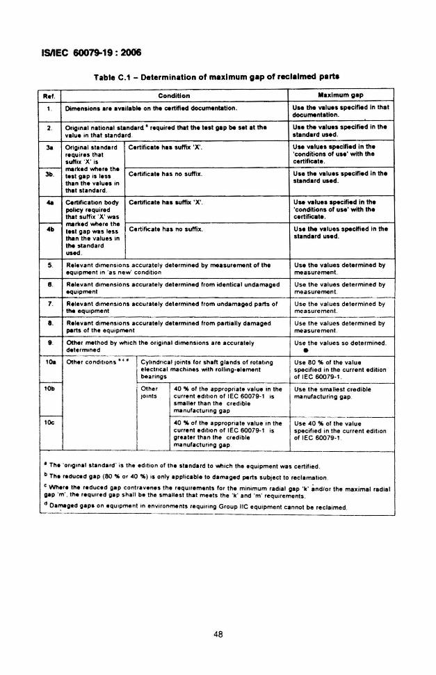
ISIIEC 60079-19: 2006
Table C.1 - Determination of maximum gap of reclaimed parts
R.f. Co ndition Mnlmumgap
,. Oirmtnaio na are a'Rilab" on the certified doeumentelion. Uae the 'Rlues apeclfled In thatdocumentation.
2. Original nati onal standard· required that the test gap be set at the Uae the va lues specified in thevelu e in that standard. standard used.
3a Origina l standa rd Certifica te hIS suffix ·X' . U.. values apecifled In therequ ires that 'conditi ons of uae' with thesuffix .X' IS certificate .
- marked where the3b . teat ga p is les s Certif ica te has no suffix. Use the va lues specified in the
than the values in standard used.
that sta nda rd .
411 Certif ication body Certificate hIS suffi x 'X' . U.. va lues specified In thepolicy requi red 'condit ions of use ' with thethat suffix 'X ' was certi fi cate .
.--- marked whe re the4b test gap was less Certif icate has no suffix , Use the values specified in the
thin the va lues in standard used,
the sta nda rdused.
5. Releva nt dime nsio ns ac cura te ly determ ined by measurement of the Use the valu es determ ined byequ ipment in 'as new' con dillon measurement.
8 . Rele va nt dime ns ions accurate ly determined Irom identi cal undamaged Use th e val ues determined byequ ip ment measurement .
7. Relevant dime ns ions accurate ly determined from undamaged parts of Use the va lues determ ined bythe equipment measurement.
a. Relevant dime nsions accurate ly determined from partia lly damaged Use the values dotermined byperts of the equ ipmenl mea suremenl.
9 . Other melhod by wh ic h the or iginal dimensions are ac curately Use the va lues so determ ined.determ,ned •
lOe Other condit ions · • • Cy hndnca ' Joint s lor sha ft g lands 01 rot aling Use 80 % 01 the valu eelectncal machines with roiling-e lement specif ied in the current ed illonbearings 01 IEC 60079·1 .
~ .-lOb Other 40 % 01 the appropnate value in the Use the smallest cred ible
JOints cu rren t ed illon 01 IEC 60079-1 is manufactu ring gap.sma lle r th an th e credIblemanufaclunng gap
~
lDc 40 "'" 01 Ihe app rop na le val ue in the Use 40 % of the val uecurrent ed it ion of IEC 60079-1 is specifi ed in the current ed it iongreater Ihan lhe cred ib le of IEC 60079·1 .manufactunng gap .
a The 'ong,nal sta nda rd ' is lhe ed lllon of the slandard to ""' ich the equ ipment was certi f ied .
b The reduce d gap (80 "4 or 40 "4) IS on ly app licable 10 damaged parts sUbject to reclamalion .
C Where the reduced gap contr av enes th e req ulleme nts for th e mi nimum radial gap 'k ' an d/or the max ima l radialgap ·m' . lhe req ulled gap sha ll be the sm allesl l hat meets the 'k' and 'm' requ rrernents .
d Oa~ged gaps on eq u ipme nt In environme nls req uinng Gro up IIC eq uipment cann ot be re cla imed.~-
48
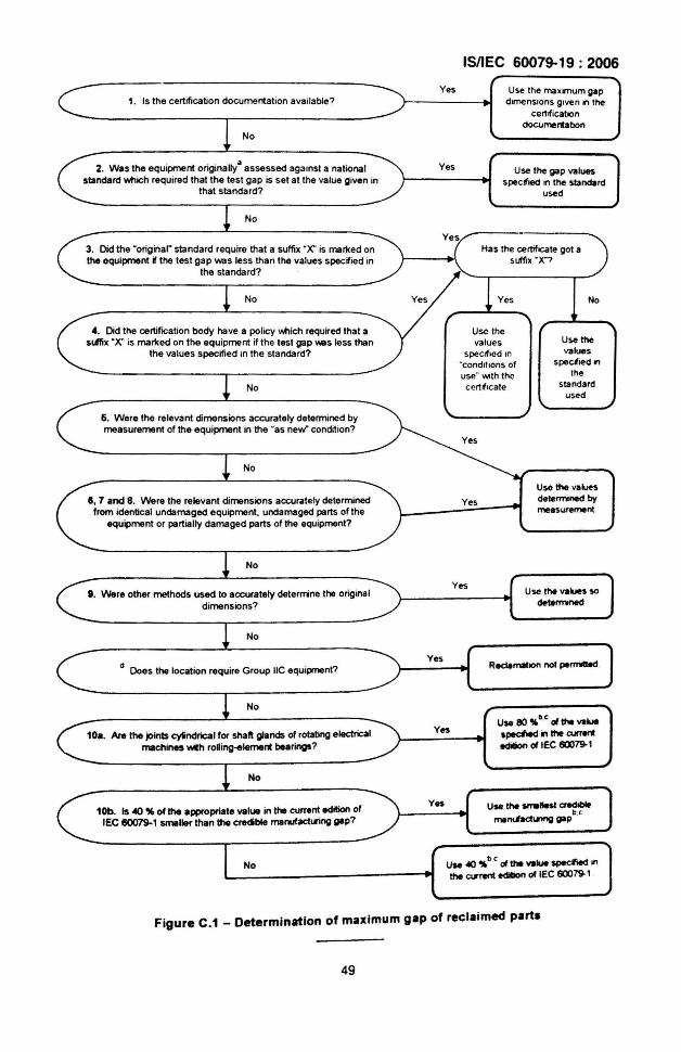
ISIIEC 60079-19: 2006
1. Is the certification documentation available?
No
Yes Use the ma.mum gapdmenslons glVi!n on the
cerMicatoondocumentabon
2. Was the equipment originally" assessed against a nationalstandard Yihich required that the test gap is sel at the value given in
that standard?
Yes Use the gap valuesspecified on the standard
used
No
No No
Use thevalues
spectl9d onIhe
standardused .
Yes
Has the cerllfocale gol asuffix ·X"?
Usc thevalues
speclflod In"condmens ofuse" WIththecertif icateNo
4. Did the certifICation body have a policy v.tlich required that asuffix ·X" is marked on the equipment if the test gap v.es less than
the values specified in the standard?
3. Did the ·original· standard require that a suffix .X' is marked onthe equipment Wthe test gap was less than the values spedied in
the standa rd?
6. Were the relevant dimensions accurately determined bymeasurement of the equipment in the "as new" condition?
No
II, 7 and 8. Were the relevant dimensions accurately determinedfrom identical undamaged equipment. undamaged parts olthe
equipment or partially damaged parts of the equipment?
Yes
Use the valuesde\ermoned bymeesuremenl
No
I . Were other methods used to accurately detennne the originaldimensions?
YesUse the values so
determned
No
d Does the location require Group IIC equipment?
No
10•. An the joints cyindrical for shaft glands of rotating electricalmachines with roRing-element bearings?
YesUse 110 %D.C d the VI....
speclied in the CUTentedilion d IEC 60079-1
No
10b. Is «>% of the appropriate value in the current edition oflEe 60079-1 smaller than the credible manufaclLnng gap?
No UN ~ %D C d the ........ spKfied onthe C16rent edilion ollEC 60079-1
Figure C.1 _ Determination of maximum gap of reclaimed part.
49
(Continued from second covet)
International Standard Title
lEG 61241-2 . Electrical apparatus for use in the presence of combustible dust Part 2: Test methods
Only the English language text has been retained while adopting it in this Indian Standard, and as suchthe page numbers given here are not the same as in the fEG Standard.
For the purpose of decid ing whether a particular requirement of this standard is complied with, the finalvalue, observed or calculated expressing the result of a test, shall be rounded off in accordance withIS 2 : 1960 'Rules for rounding off numerical values (revised)' .The number of significant places retainedin the rounded off value should be the same as that of the specified value in this standard.
Bureau of Indian Standards
BIS is a statutory institution established under the Bureau of Indian Standards Act, 1986 to promoteharmonious development of the activities of standardization, marking and quality certification ofgoods and attending to connected matters in the country.
Copyright
BIS has the copyright of all its publications. No part of these publications may be reproduced in anyform without the prior permission in writing of BIS. This does not preclude the free use, in the courseof implementing the standard, of necessary details, such as symbols and sizes, type or gradedesignations. Enquiries relating to copyright be addressed to the Director (PUblications), BIS .
Review of Indian Standards
Amendments are issued to standards as the need arises on the basis of comments. Standards arealso reviewedperiodically; a standard along with amendments is reaffirmed when such review indicatesthat nochanges are needed; if the review indicates that changes are needed, it is taken up for revision .Users of Indian Standards should ascertain that they are in possession of the latest amendments oredition by referring to the latest issue of 'BIS Catalogue' and 'Standards: Monthly Additions'.
This Indian Standard has been developed from Doc: No. ETD 22 (5727).
Amendments Issued Since Publication
Amend No. Date of Issue
BUREAU OF INDIAN STANDARDS
Text Affected
{2337 8499, 2337 856123378626,23379120
{260 38432609285
Headquarters:
Manak Bhavan, 9 Bahadur Shah Zafar Marg, New Delhi 110002Telephones: 2323 0131, 23233375,23239402 website : www.bis.org.in
Regional Offices:
Central : Manak Bhavan, 9 Bahadur Shah Zatar MargNEW DELHI 110002
Eastern : 1/14 C.I.T. Scheme VII M, V.I.P.Road, KankurgachiKOlKATA 700054
Northern : SCO 335-336, Sector 34-A, CHANDIGARH 160022
Telephones
{2323 761723233841
Southern : C.I.T.Campus, IV Cross Road, CHENNAI 600113{
2254 1216,2254 14422254 2519, 2254 2315
Western : Manakalaya, E9 MIDC, Marol, Andheri (East) {2832 9295, 2832 7858MUMBAI 400093 2832 7891, 2832 7892
Branches : AHMEDABAD. BANGALORE. BHOPAL.BHUBANESHWAR. COIMBATORE. FARIDABAD.GHAZIABAD. GUWAHATI. HYDERABAD. JAIPUR. KANPUR. LUCKNOW. NAGPUR.PARWANOO. PATNA. PUNE. RAJKOT. THIRUVANANTHAPURAM. VISAKHAPATNAM.
Printed at Simco Printing Press, Delhi