Embed Size (px)
Citation preview


Edition 1 - 2010 © CCNR/OCIMF 2010 i
ISGINTT
International Safety Guide for Inland Navigation Tank-barges and Terminals
First Edition
CENTRAL COMMISSION FOR THE NAVIGATION OF THE RHINE OIL COMPANIES INTERNATIONAL MARINE FORUM

International Safety Guide for Inland Navigation Tank-barges and Terminals
Edition 1 - 2010 © CCNR/OCIMF 2010 ii
International Safety Guide for Inland Navigation Tank-barges and Terminals
Edition 1 - 2010 © CCNR/OCIMF 2010 iii
Published 2010
© Central Commission for the Navigation of the Rhine, Strasbourg and
Oil Companies International Marine Forum
ISBN 978-2-7466-2185-5 The Central Commission for the Navigation of the Rhine (CCNR) is an international organisation created by the Congress of Vienna and ruled by the Revised Convention for the Navigation of the Rhine. The Oil Companies International Marine Forum (OCIMF) is a voluntary association of oil companies having an interest in the shipment and terminalling of crude oil and oil products. OCIMF is organised to represent its membership before, and consult with, the International Maritime Organization and other government bodies on matters relating to the shipment and terminalling of crude oil and oil products, including marine pollution and safety.
Notice of Terms of Use
While the information and advice given in this guide (Guide) has been developed using the best information currently available, it is intended purely as guidance to be used at the user’s own risk. No warranties or representations are given nor is any duty of care or responsibility accepted by the Central Commission for the Navigation of the Rhine (CCNR), the Oil Companies International Marine Forum (OCIMF), or their employees, members, contractors or by any person, firm, company or organisation who or which has been in any way concerned with the furnishing of information or data, the compilation or any translation, publishing, supply of the Guide, for the accuracy of any information or advice in the Guide or any omission from the Guide or for any consequence whatsoever resulting directly or indirectly from compliance with, adoption of, or reliance on guidance contained in the Guide even if caused by failure to exercise reasonable care. The user should note that the electronic web based version of the Guide is distributed free of charge. This Guide was produced in English and translated into [German, French, Dutch] editions (“the Editions”).
The official text of this Guide is in English. In the event of any differences between the English text Guide and any or all of the Editions, the English text Guide will take precedence.
Published and Printed by Central Commission for the Navigation of the Rhine
2, Place de la République 67082 Strasbourg Cedex, France
Tel. No: +33 (0)388 52 20 10 Fax No: +33 (0)388 32 10 72
www.ccr-zkr.org

International Safety Guide for Inland Navigation Tank-barges and Terminals
Edition 1 - 2010 © CCNR/OCIMF 2010 iv

International Safety Guide Foreword for Inland Navigation Tank-barges and Terminals
Edition 1 - 2010 © CCNR/OCIMF 2010 v
FOREWORD The CCNR, together with other international bodies, provides the forum for developing and adopting and, thereafter, reviewing and updating, as may be necessary, the regulatory framework within which navigation on the Rhine and other European waterways operates. In the years since the adoption by CCNR of the Regulation concerning the Carriage of Dangerous Goods on the Rhine (ADNR)1, the safety and security record and the environmental performance of the inland tank-barge industry in Europe has improved considerably. Such an improvement, however, cannot be brought about by regulation alone; it is also testimony to the good practices adopted and constantly refined by industry, and the dedication to safety and environmental protection of the people it employs. One of the main functions of the international associations that have prepared this publication is to represent the industry’s interests at regulatory bodies such as the Central Commission for the Navigation of the Rhine (CCNR) and the International Maritime Organization (IMO). The European Chemical Industry Council (CEFIC), the European Barge Union (EBU), the European Skippers Organization (ESO), the European Petroleum Industry Association (EUROPIA), the European Sea Ports Organisation (ESPO), the Federation of European Tank Storage (FETSA), the Oil Companies International Marine Forum (OCIMF), and the Society of International Gas Tanker and Terminal Operators (SIGTTO) all contribute to various extents to the work of these regulatory bodies. This commitment to continuous improvement is demonstrated by the industry’s efforts to develop the International Safety Guide for Inland Tank-barges and Terminals – or ISGINTT, as it is known within the industry. It therefore gives us great pleasure to introduce this first edition of the Guide. The CCNR recognises ISGINTT as the principal industry reference manual on the safe operation of tankers and the terminals that serve them. This Guide provides best known safety practices on the operation of tank-barges and terminals and also embraces a risk-based control philosophy. By enhancing risk awareness, ISGINTT seeks to foster an environment where the uncertainties associated with some shipboard operations are reduced not solely by prescription, but also by encouraging barge and terminal crew, as well as their employers, to identify the risks in everything they are doing and to then implement fit-for-purpose risk reduction measures. This puts the focus on people and is, therefore, entirely consistent with a strategy related to the human element. We are confident that ISGINTT will not only contribute to the further improvement of the industry’s excellent safety record but will also bring us closer to the goal of zero accidents to which we all aspire. We, therefore, commend it to all interested parties. In order to ensure wide-spread use, the Guide will also be published in the working languages of the CCNR, i.e. Dutch, French and German. We wish to thank the CCNR member states, as well as the organisations and companies mentioned in the back of the Guide who, with their financial contributions, have made the translation of the Guide into these languages possible.
Jean-Marie Woehrling Secretary-General Central Commission for the Navigation of the Rhine
Captain David Cotterell Director Oil Companies International Marine Forum (OCIMF) 1 In 2011 the ADNR will be replaced by the “European Agreement concerning the International Carriage of Dangerous Goods
by Inland Waterways” (ADN) which will be adopted by most member states of the European Union as required by Directive 2008/68/EC and of the United Nations Economic Committee for Europe (UN ECE).

International Safety Guide Foreword for Inland Navigation Tank-barges and Terminals
Edition 1 - 2010 © CCNR/OCIMF 2010 vi
International Safety Guide Introduction for Inland Navigation Tank-barges and Terminals
Edition 1 - 2010 © CCNR/OCIMF 2010 vii
INTRODUCTION Safety is critical to the tanker industry. The authors of the International Safety Guide for Inland Tank-barges and Terminals (ISGINTT) hope that the Guide will become the standard reference work on the safe operation of inland tank-barges and the terminals they serve. To do so, the Guide must keep abreast of changes in tanker design and operating practice, and reflect the latest technology and legislation. In this text, account has been taken of the latest thinking on a number of issues including the generation of static electricity and stray currents. The Safety Check-Lists contained in the Guide cover ship/shore as well ship/barge (and vice versa) transhipment of cargo and slops. The authors hope that these Check-Lists comprehensively reflect the individual and joint responsibilities of the tank-barge and the terminal and that the Check-Lists will be adopted universally by ports and terminals. The Guide is divided into five sections: “General Information”; “Tanker Information”; “Terminal Information”, the “Management of the Tanker and Terminal Interface” and “Additional Information for the Handling of Liquefied Gases”. The OCIMF “International Safety Guide for Oil Tankers and Terminals” (ISGOTT), 5th Edition and, for certain chapters dealing with gaseous products, the SIGTTO “Liquefied Gas Handling Principles on Ships and In Terminals” were used as templates to avoid gaps and assure compatibility in ship/barge interfaces. Use of any OCIMF and SIGTTO publications in the development of ISGINTT is in no way intended to constitute a waiver of any of the intellectual property rights of OCIMF and SIGTTO in the publication. All intellectual property rights shall be respected. The authors believe that ISGINTT will provide the best technical guidance on inland tank-barge and terminal operations. All operators are urged to ensure that the recommendations in this Guide are not only read and fully understood, but also followed. The CCNR has established the ISGINTT Secretariat to support the initial development of the ISGINTT and to ensure its foreseen regular update in the future. The Secretariat encourages the users of the ISGINTT to transmit comments and suggestions for improvement for possible inclusion in future editions. The ISGINTT website not only provides the latest information on the ISGINTT, but serves also as the communication link between users of the ISGINTT on the one side and the experts and organisations, who participated in its development, on the other side. The ISGINTT website can be found at www.isgintt.org, the ISGINTT Secretariat can be reached by email at [email protected]. Central Commission for the Navigation of the Rhine (CCNR) 2, place de la République 67082 Strasbourg Cedex France www.ccr-zkr.org Oil Companies International Marine Forum (OCIMF) 29 Queen Anne’s Gate London SW1H 9BU United Kingdom www.ocimf.com

International Safety Guide Introduction for Inland Navigation Tank-barges and Terminals
Edition 1 - 2010 © CCNR/OCIMF 2010 viii
International Association of Ports and Harbors 7th Floor, South Tower New Pier Takeshiba 1-16-1, Kaigan, Minato-ku Tokyo 105-0022 Japan www.iaphworldports.org International Chamber of Shipping 12 Carthusian Street London EC1M 6EZ United Kingdom www.marisec.org European Chemical Industry Council Avenue E. van Nieuwenhuyse, 4 box 1 1160 Brussels Belgium www.cefic.org European Barge Union Vasteland 12e 3011 BL Rotterdam The Netherlands www.ebu-uenf.org European Skippers Organization Voorhavenstraat 2 1000 Brussels Belgium www.eso-oeb.org European Petroleum Industry Association Boulevard du Souverain 165 - 3rd Floor 1160 Brussels Belgium www.europia.com European Sea Ports Organisation Treurenberg 6 1000 Brussels Belgium www.espo.be Federation of European Tank Storage Rue des Colonies 11 1000 Brussels Belgium www.fetsa,com Society of International Gas Tanker and Terminal Operators 17 St Helen's Place London EC3A 6DG United Kingdom www.sigtto.org

International Safety Guide Contents for Inland Navigation Tank-barges and Terminals
Edition 1 - 2010 © CCNR/OCIMF 2010 ix
CONTENTS FOREWORD ................................................................................................................................ v INTRODUCTION ........................................................................................................................... vii PURPOSE AND SCOPE .............................................................................................................. xxxiii BIBLIOGRAPHY .......................................................................................................................... xxxv DEFINITIONS ............................................................................................................................... xxxix PART 1 - GENERAL INFORMATION .......................................................................... 1 CHAPTER 1 – BASIC PROPERTIES OF BULK LIQUIDS .........................................................… 3
1.1 Vapour Pressure .............................................................................................................. 3 1.1.1 True Vapour Pressure ...................................................................................... 3 1.1.2 Reid Vapour Pressure ...................................................................................... 4
1.2 Flammability ..................................................................................................................... 4 1.2.1 General ............................................................................................................. 4 1.2.2 Explosive Limits ................................................................................................ 4 1.2.3 Effect of Inert Gas on Flammability .................................................................. 4 1.2.4 Tests for Flammability ...................................................................................... 6 1.2.5 Flashpoint ......................................................................................................... 6 1.2.6 Flammability Classification ............................................................................... 6
1.3 Density of Hydrocarbon Gases ........................................................................................ 8
1.4 Corrosiveness .................................................................................................................. 9
CHAPTER 2 - HAZARDS OF BULK LIQUIDS ............................................................................ 11
2.1 Flammability ..................................................................................................................... 11
2.2 Density ............................................................................................................................. 11
2.3 Toxicity ............................................................................................................................. 11 2.3.1 Introduction ....................................................................................................... 11 2.3.2 Bulk Liquids ...................................................................................................... 12 2.3.3 Product vapours ............................................................................................... 13 2.3.4 Material Safety Data Sheets (MSDS) / Safety Data Sheets (SDS) ................ 14 2.3.5 Benzene, other CMR-Products and Aromatic Hydrocarbons .......................... 14

International Safety Guide Contents for Inland Navigation Tank-barges and Terminals
Edition 1 - 2010 © CCNR/OCIMF 2010 x
2.3.6 Hydrogen Sulphide (H2S) ................................................................................. 15 2.3.7 Mercaptans ....................................................................................................... 20 2.3.8 Gasolines Containing Tetraethyl Lead (TEL) or Tetramethyl Lead (TML)........ 20 2.3.9 Inert Gas ........................................................................................................... 20 2.3.10 Oxygen Deficiency ........................................................................................... 21 2.3.11 FAME (Fatty Acid Methyl Ester) ....................................................................... 21 2.3.12 MTBE/ETBE ..................................................................................................... 21 2.3.13 Ethanol ............................................................................................................. 22
2.4 Gas Measurement ........................................................................................................... 22 2.4.1 Introduction ....................................................................................................... 22 2.4.2 Measurement of Product Concentration .......................................................... 23 2.4.3 Flammable Gas Monitors (Explosimeters) ....................................................... 23 2.4.4 Non-Catalytic Heated Filament Gas Indicators (Tankscopes) ......................... 26 2.4.5 Inferometer (Refractive Index Meter) ............................................................... 28 2.4.6 Infra-red (IR) Instruments ................................................................................. 29 2.4.7 Measurement of Low Concentrations of Toxic Gases ..................................... 31 2.4.8 Fixed Gas Detection Installations ..................................................................... 32 2.4.9 Measurement of Oxygen Concentrations ......................................................... 32 2.4.10 Use of Oxygen Analysers ................................................................................. 33 2.4.11 Multi-gas Instruments ....................................................................................... 34 2.4.12 Personal Gas Monitors ..................................................................................... 34 2.4.13 Gas Sample Lines and Sampling Procedures ................................................. 35
2.5 Product Gas Evolution and Dispersion ............................................................................ 36 2.5.1 Introduction........................................................................................................ 36 2.5.2 Gas Evolution and Venting................................................................................ 37 2.5.3 Gas Dispersion.................................................................................................. 39 2.5.4 Variables Affecting Dispersion .......................................................................... 39 2.5.5 Minimising Hazards from Vented Gas............................................................... 45 2.5.6 N/A .................................................................................................................... 47
2.6 N/A ................................................................................................................................... 47
2.7 The Hazards Associated with the Handling, Storage and Carriage of Residual Products ........................................................................................................................... 47 2.7.1 General ............................................................................................................. 47 2.7.2 Nature of Hazard .............................................................................................. 47 2.7.3 Flashpoint and Headspace Flammability Measurement .................................. 48 2.7.4 Precautionary Measures .................................................................................. 48 2.7.5 Hydrogen Sulphide Hazard in Residual Fuel Oils ............................................ 49

International Safety Guide Contents for Inland Navigation Tank-barges and Terminals
Edition 1 - 2010 © CCNR/OCIMF 2010 xi
CHAPTER 3 - STATIC ELECTRICITY ........................................................................................ 51
3.1 Principles of Electrostatics ............................................................................................... 51 3.1.1 Summary .......................................................................................................... 51 3.1.2 Charge Separation ........................................................................................... 52 3.1.3 Charge Accumulation ....................................................................................... 53 3.1.4 Electrostatic Discharge ..................................................................................... 53 3.1.5 Electrostatic Properties of Gases and Mists .................................................... 57
3.2 General Precautions Against Electrostatic Hazards ........................................................ 57 3.2.1 Overview .......................................................................................................... 57 3.2.2 Bonding ............................................................................................................ 59 3.2.3 Avoiding Loose Conductive Objects ................................................................ 60
3.3 Other Sources of Electrostatic Hazards .......................................................................... 60 3.3.1 Filters ................................................................................................................ 60 3.3.2 Fixed Equipment in Cargo Tanks ..................................................................... 60 3.3.3 Free Fall in Tanks ............................................................................................. 61 3.3.4 Water Mists ...................................................................................................... 61 3.3.5 Inert Gas ........................................................................................................... 62 3.3.6 Discharge of Carbon Dioxide ........................................................................... 62 3.3.7 Clothing and Footwear ..................................................................................... 63 3.3.8 Synthetic Materials ............................................................................................ 63
CHAPTER 4 - GENERAL HAZARDS FOR TANKER AND TERMINAL .................................... 65
4.1 General Principles ........................................................................................................... 65
4.2 Control of Potential Ignition Sources ............................................................................... 66 4.2.1 Naked Lights .................................................................................................... 66 4.2.2 Smoking ........................................................................................................... 66 4.2.3 Galley Stoves and Cooking Appliances ........................................................... 68 4.2.4 Engine and Boiler Rooms ................................................................................ 68
4.3 Portable Electrical Equipment ......................................................................................... 69 4.3.1 General ............................................................................................................. 69 4.3.2 Lamps and Other Electrical Equipment on Flexible Cables (Wandering
Leads) .............................................................................................................. 69 4.3.3 Air Driven Lamps .............................................................................................. 69 4.3.4 Torches (Flashlights), Lamps and Portable Battery Powered Equipment ....... 69 4.3.5 Cameras ........................................................................................................... 70 4.3.6 Other Portable Electrical Equipment ................................................................ 70

International Safety Guide Contents for Inland Navigation Tank-barges and Terminals
Edition 1 - 2010 © CCNR/OCIMF 2010 xii
4.4 Management of Electrical Equipment and Installations in Dangerous Areas .................. 71
4.4.1 General ............................................................................................................. 71 4.4.2 Dangerous and Hazardous Areas .................................................................... 71 4.4.3 Electrical Equipment ......................................................................................... 72 4.4.4 Inspection and Maintenance of Electrical Equipment ...................................... 73 4.4.5 Electrical Repairs, Maintenance and Test Work at Terminals ......................... 74
4.5 Use of Tools ..................................................................................................................... 75 4.5.1 Grit Blasting and Mechanically Powered Tools ................................................ 75 4.5.2 Hand Tools ........................................................................................................ 76
4.6 Equipment Made of Aluminium ........................................................................................ 76
4.7 Cathodic Protection Anodes in Cargo Tanks .................................................................. 76
4.8 Communications Equipment ............................................................................................ 77 4.8.1 General ............................................................................................................. 77 4.8.2 Tanker’s Radio Equipment ............................................................................... 77 4.8.3 Tanker’s Radar Equipment .............................................................................. 78 4.8.4 Automatic Identification Systems (AIS) ............................................................ 78 4.8.5 Telephones ....................................................................................................... 79 4.8.6 Mobile Telephones ........................................................................................... 79 4.8.7 Pagers .............................................................................................................. 79
4.9 Spontaneous Combustion ............................................................................................... 80
4.10 Auto-Ignition ..................................................................................................................... 80
4.11 Asbestos .......................................................................................................................... 80
CHAPTER 5 - FIRE-FIGHTING ................................................................................................... 81
5.1 Theory of Fire-Fighting .................................................................................................... 81
5.2 Types of Fire and Appropriate Extinguishing Agents ...................................................... 81 5.2.1 Class A - Fires Involving Solid Materials, Usually of an Organic Nature,
in which Combustion Normally Takes Place with the Formation of Glowing Embers ............................................................................................... 81
5.2.2 Class B - Fires Involving Liquids or Liquefiable Solids .................................... 81 5.2.3 Class C - Fires Involving Gases ....................................................................... 82 5.2.4 Class D - Fires Involving Metals ....................................................................... 83 5.2.5 Class F - Fires Involving Cooking Media (Vegetable or Animal Oils and
Fats) in Cooking Appliances ............................................................................ 83 5.2.6 Electrical Equipment Fires ............................................................................... 83
5.3 Extinguishing Agents ....................................................................................................... 83 5.3.1 Cooling Agents ................................................................................................. 83 5.3.2 Smothering Agents ........................................................................................... 84 5.3.3 Flame Inhibiting Agents .................................................................................... 86
5.4 Fire Detection Systems .................................................................................................... 87
5.5 General Precautions ........................................................................................................ 87
International Safety Guide Contents for Inland Navigation Tank-barges and Terminals
Edition 1 - 2010 © CCNR/OCIMF 2010 xiii
CHAPTER 6 -SECURITY ............................................................................................................. 89
6.1 General ............................................................................................................................. 89
6.2 Security Assessments ..................................................................................................... 89
6.3 Responsibilities Under the ISPS Code ............................................................................ 90
6.4 Security Plans .................................................................................................................. 90
6.5 Security Plans for Inland Tankers .................................................................................... 91
6.6 Declaration of Security (DoS) .......................................................................................... 92
PART 2 - TANKER INFORMATION ............................................................................. 95
CHAPTER 7 - SHIPBOARD SYSTEMS ...................................................................................... 97
7.1 Fixed Inert Gas Systems ................................................................................................. 97 7.1.1 General ............................................................................................................. 97 7.1.2 Sources of Inert Gas ........................................................................................ 97 7.1.3 Composition and Quality of Inert Gas .............................................................. 98 7.1.4 Methods of Replacing Tank Atmospheres ....................................................... 98 7.1.5 Cargo Tank Atmosphere Control ..................................................................... 99 7.1.6 Application to Cargo Tank Operations ............................................................. 99 7.1.7 Precautions to be Taken to Avoid Health Hazards .......................................... 103 7.1.8 Cargo Tank Protection Against Over/Under-Pressure ..................................... 104 7.1.9 N/A .................................................................................................................... 105 7.1.10 N/A .................................................................................................................... 105 7.1.11 Cold Weather Precautions for Inert Gas Systems ........................................... 105 7.1.12 Inert Gas System Failure ................................................................................. 106 7.1.13 Inert Gas Plant Repairs .................................................................................... 107
7.2 Venting Systems .............................................................................................................. 107 7.2.1 General ............................................................................................................. 107 7.2.2 Tank Over-Pressurisation and Under-Pressurisation ....................................... 108
7.3 Cargo and Ballast Systems ............................................................................................. 110 7.3.1 Operation Manual ............................................................................................. 110 7.3.2 Cargo and Ballast System Integrity .................................................................. 110 7.3.3 Loading Rates .................................................................................................. 111 7.3.4 Monitoring of Void and Ballast Spaces ............................................................ 113
7.4 Power and Propulsion Systems ....................................................................................... 113
7.5 N/A ................................................................................................................................... 113
7.6 N/A ................................................................................................................................... 113

International Safety Guide Contents for Inland Navigation Tank-barges and Terminals
Edition 1 - 2010 © CCNR/OCIMF 2010 xiv
CHAPTER 8 - SHIP’S EQUIPMENT ............................................................................................ 115
8.1 Shipboard Fire-Fighting Equipment ................................................................................. 115 8.1.1 General ............................................................................................................. 115 8.1.2 Tanker Fixed Fire-Fighting Installations - Cooling ........................................... 115 8.1.3 Tanker Fixed Fire-Fighting Installations - Smothering ..................................... 115 8.1.4 Portable Fire Extinguishers .............................................................................. 116
8.2 Gas Testing Equipment ................................................................................................... 117 8.2.1 Introduction ....................................................................................................... 117 8.2.2 Summary of Gas Testing Tasks ....................................................................... 118 8.2.3 The Provision of Gas Measuring Instruments .................................................. 119 8.2.4 Alarm Functions on Gas Measuring Instruments ............................................. 119 8.2.5 Sampling Lines ................................................................................................. 119 8.2.6 Calibration ........................................................................................................ 120 8.2.7 Operational Testing and Inspection ................................................................. 120 8.2.8 Disposable Personal Gas Monitors .................................................................. 121
8.3 Lifting Equipment ............................................................................................................. 121 8.3.1 Inspection and Maintenance ............................................................................ 121 8.3.2 Training ............................................................................................................ 122
CHAPTER 9 - MANAGEMENT OF SAFETY AND EMERGENCIES .......................................... 123
9.1 The International Safety Management (ISM) Code ......................................................... 123
9.2 Safety Management Systems .......................................................................................... 124 9.2.1 Risk Assessment .............................................................................................. 125
9.3 Permit to Work Systems .................................................................................................. 125 9.3.1 General ............................................................................................................. 125 9.3.2 Permit to Work Systems - Structure ................................................................. 126 9.3.3 Permit to Work Systems - Principles of Operation ........................................... 127 9.3.4 Permit to Work Forms ...................................................................................... 127 9.3.5 Work Planning Meetings .................................................................................. 128
9.4 Hot Work .......................................................................................................................... 128 9.4.1 Control of Hot Work .......................................................................................... 128 9.4.2 Hot Work Inside a Designated Space .............................................................. 128 9.4.3 Hot Work Outside a Designated Space ........................................................... 129 9.4.4 Hot Work in Dangerous or Hazardous Areas ................................................... 131
9.5 Welding and Burning Equipment ..................................................................................... 137
9.6 Other Hazardous Tasks ................................................................................................... 137
9.7 Management of Contractors ............................................................................................ 138

International Safety Guide Contents for Inland Navigation Tank-barges and Terminals
Edition 1 - 2010 © CCNR/OCIMF 2010 xv
9.8 Repairs at a Facility Other Than a Shipyard ................................................................... 138
9.8.1 Introduction ....................................................................................................... 138 9.8.2 General ............................................................................................................. 138 9.8.3 Supervision and Control ................................................................................... 139 9.8.4 Pre-Arrival Planning ......................................................................................... 139 9.8.5 Mooring Arrangements ..................................................................................... 139 9.8.6 Shore Facilities ................................................................................................. 140 9.8.7 Pre-Work Safety Meeting ................................................................................. 140 9.8.8 Work Permits .................................................................................................... 141 9.8.9 Tank Condition ................................................................................................. 141 9.8.10 Cargo Lines ...................................................................................................... 141 9.8.11 Fire-Fighting Precautions ................................................................................. 142 9.8.12 Dedicated Safety Responsible Person ............................................................. 142 9.8.13 Hot Work .......................................................................................................... 142
9.9 Shipboard Emergency Management ............................................................................... 143 9.9.1 General ............................................................................................................. 143 9.9.2 Tanker Emergency Plan ................................................................................... 143 9.9.3 Actions in the Event of an Emergency ............................................................. 145
CHAPTER 10 - ENCLOSED SPACES ........................................................................................ 147
10.1 Definition and General Caution ....................................................................................... 147
10.2 Hazards of Enclosed Spaces .......................................................................................... 147 10.2.1 Assessment of Risk .......................................................................................... 147 10.2.2 Respiratory Hazards ......................................................................................... 148 10.2.3 Cargo Vapours and Toxic Gases ..................................................................... 148 10.2.4 Particular Toxic Vapours .................................................................................. 149 10.2.5 Oxygen Deficiency ........................................................................................... 149 10.2.6 N/A .................................................................................................................... 150
10.3 Atmosphere Tests Prior to Entry ..................................................................................... 150
10.4 Control of Entry into Enclosed Spaces ............................................................................ 151
10.5 Safeguards for Enclosed Space Entry ............................................................................. 152
10.6 Emergency Procedures ................................................................................................... 153 10.6.1 Evacuation from Enclosed Spaces .................................................................. 153 10.6.2 Rescue from Enclosed Spaces ........................................................................ 153 10.6.3 Resuscitation .................................................................................................... 153
10.7 Entry into Enclosed Spaces with Atmospheres Known or Suspected to be Unsafe for Entry ........................................................................................................................... 154

International Safety Guide Contents for Inland Navigation Tank-barges and Terminals
Edition 1 - 2010 © CCNR/OCIMF 2010 xvi
10.8 Respiratory Protective Equipment ................................................................................... 155
10.8.1 Self-Contained Breathing Apparatus (SCBA) .................................................. 155 10.8.2 Air Line Breathing Apparatus ........................................................................... 156 10.8.3 Emergency Escape Breathing Device (EEBD) ................................................ 157 10.8.4 Cartridge or Canister Face Masks ................................................................... 158 10.8.5 Hose Mask (Fresh Air Breathing Apparatus) ................................................... 159 10.8.6 Equipment Maintenance .................................................................................. 159 10.8.7 Stowage ........................................................................................................... 159 10.8.8 Training ............................................................................................................ 159
10.9 Work in Enclosed Spaces ................................................................................................ 159 10.9.1 General Requirements ..................................................................................... 159 10.9.2 Opening Equipment and Fittings ...................................................................... 160 10.9.3 Use of Tools ..................................................................................................... 160 10.9.4 Use of Electric Lights and Electrical Equipment .............................................. 160 10.9.5 Removal of Sludge, Scale and Sediment ......................................................... 160 10.9.6 N/A .................................................................................................................... 160
10.10 Pumproom Entry Precautions .......................................................................................... 161 10.10.1 Ventilation ......................................................................................................... 161 10.10.2 Pumproom Entry Procedures ........................................................................... 161
10.11 Pumproom Operational Precautions ............................................................................... 162 10.11.1 General Precautions ......................................................................................... 162 10.11.2 Cargo and Ballast Line Draining Procedures ................................................... 163 10.11.3 Routine Maintenance and Housekeeping Issues ............................................. 163 10.11.4 Maintenance of Electrical Equipment in the Pumproom .................................. 164 10.11.5 Inspection and Maintenance of Pumproom Ventilation Fans .......................... 164 10.11.6 Testing of Alarms and Trips ............................................................................. 164 10.11.7 Miscellaneous ................................................................................................... 164
CHAPTER 11 - SHIPBOARD OPERATIONS ............................................................................. 167
11.1 Cargo Operations ............................................................................................................ 167 11.1.1 General ............................................................................................................. 167 11.1.2 Setting of Lines and Valves .............................................................................. 167 11.1.3 Valve Operation ................................................................................................ 167 11.1.4 Pressure Surges ............................................................................................... 168 11.1.5 Butterfly and Non-Return (Check) Valves ........................................................ 168 11.1.6 Loading Procedures ......................................................................................... 168 11.1.7 Loading Static Accumulator Oils ...................................................................... 173 11.1.8 Loading Very High Vapour Pressure Cargoes ................................................. 180 11.1.9 Loading Cargoes Containing Hydrogen Sulphide (H2S) .................................. 181 11.1.10 Loading Cargoes Containing Benzene ............................................................ 182

International Safety Guide Contents for Inland Navigation Tank-barges and Terminals
Edition 1 - 2010 © CCNR/OCIMF 2010 xvii
11.1.11 Loading Heated Products ................................................................................. 182 11.1.12 Loading Over the Top (sometimes known as ‘Loading Overall’) ..................... 183 11.1.13 Loading at Terminals Having Vapour Emission Control (VEC) Systems ......... 183 11.1.14 Discharging Procedures ................................................................................... 186 11.1.15 Pipeline and Hose Clearing Following Cargo Operations ................................ 189
11.2 Stability, Stress, Trim and Sloshing Considerations ........................................................ 192 11.2.1 General ............................................................................................................. 192 11.2.2 Free Surface Effects ......................................................................................... 192 11.2.3 Sloshing ............................................................................................................ 193 11.2.4 Loading and Discharge Planning ..................................................................... 193
11.3 Tank Cleaning .................................................................................................................. 194 11.3.1 General ............................................................................................................. 194 11.3.2 Tank Washing Risk Management .................................................................... 194 11.3.3 Supervision and Preparation ............................................................................ 195 11.3.4 Tank Atmospheres ........................................................................................... 195 11.3.5 Tank Washing .................................................................................................. 196 11.3.6 Precautions for Tank Washing ......................................................................... 200
11.4 Gas Freeing ..................................................................................................................... 203 11.4.1 General ............................................................................................................. 203 11.4.2 Gas Free for Entry Without Breathing Apparatus ............................................ 203 11.4.3 Procedures and Precautions ............................................................................ 204 11.4.4 Gas Testing and Measurement ........................................................................ 205 11.4.5 Fixed Gas Freeing Equipment ......................................................................... 205 11.4.6 Portable Fans ................................................................................................... 205 11.4.7 Ventilating Double Hull Ballast Tanks .............................................................. 206 11.4.8 Gas Freeing in Preparation for Hot Work ......................................................... 206
11.5 N/A ................................................................................................................................... 206
11.6 Ballast Operations ........................................................................................................... 206 11.6.1 Introduction ....................................................................................................... 206 11.6.2 General ............................................................................................................. 206 11.6.3 Loading Cargo Tank Ballast ............................................................................. 206 11.6.4 Loading Segregated Ballast ............................................................................. 207 11.6.5 Deballasting in Port .......................................................................................... 208 11.6.6 Discharging Segregated Ballast ....................................................................... 208 11.6.7 N/A .................................................................................................................... 209 11.6.8 N/A .................................................................................................................... 209

International Safety Guide Contents for Inland Navigation Tank-barges and Terminals
Edition 1 - 2010 © CCNR/OCIMF 2010 xviii
11.7 Cargo Leakage into Double Hull Tanks ........................................................................... 209 11.7.1 Action to be Taken ........................................................................................... 209 11.7.2 N/A .................................................................................................................... 210
11.8 Cargo Measurement, Ullaging, Dipping and Sampling ................................................... 210 11.8.1 General ............................................................................................................. 210 11.8.2 Measuring and Sampling Non-Inerted Tanks .................................................. 211 11.8.3 Measuring and Sampling Inerted Tanks .......................................................... 214 11.8.4 Measuring and Sampling Cargoes Containing Toxic Substances ................... 217 11.8.5 Closed Gauging for Custody Transfer .............................................................. 217
11.9 Transfers Between Vessels ............................................................................................. 218 11.9.1 Tanker-to-Tanker Transfers ............................................................................. 218 11.9.2 Seegoing Vessel-to-Inland Tanker and Inland Tanker-to-Seegoing
Vessel ............................................................................................................... 218 11.9.3 Tanker-to-Tanker Transfers Using Vapour Balancing ..................................... 219 11.9.4 Tanker-to-Tanker Transfers Using Terminal Facilities ..................................... 219 11.9.5 Tanker-to-Tanker Electric Currents .................................................................. 219
CHAPTER 12 - CARRIAGE AND STORAGE OF HAZARDOUS MATERIALS ......................... 221
12.1 Liquefied Gases ............................................................................................................... 221
12.2 Tanker’s Stores ................................................................................................................ 222 12.2.1 General ............................................................................................................. 222 12.2.2 Paint ................................................................................................................. 222 12.2.3 Chemicals ......................................................................................................... 222 12.2.4 Cleaning Liquids ............................................................................................... 222 12.2.5 Spare Gear Storage ......................................................................................... 222
12.3 Cargo and Bunker Samples ............................................................................................ 223
12.4 Other Materials ................................................................................................................ 223 12.4.1 Sawdust, Oil Absorbent Granules and Pads .................................................... 223 12.4.2 Garbage ........................................................................................................... 223

International Safety Guide Contents for Inland Navigation Tank-barges and Terminals
Edition 1 - 2010 © CCNR/OCIMF 2010 xix
12.5 Packaged Cargoes .......................................................................................................... 223
12.5.1 Petroleum and Other Flammable Liquids ......................................................... 223 12.5.2 N/A .................................................................................................................... 225 12.5.3 Entry into Holds ................................................................................................ 225 12.5.4 Portable Electrical Equipment .......................................................................... 225 12.5.5 Smothering Type Fire Extinguishing Systems ................................................. 225 12.5.6 Fire-Fighting Precautions ................................................................................. 225 12.5.7 Forecastle Spaces ............................................................................................ 225 12.5.8 Material Stowed on Deck ................................................................................. 226 12.5.9 N/A .................................................................................................................... 226
CHAPTER 13 - HUMAN ELEMENT CONSIDERATIONS .......................................................... 227
13.1 Manning Levels ................................................................................................................ 227
13.2 Training and Experience .................................................................................................. 228
13.3 Hours of Rest ................................................................................................................... 229 13.3.1 Statutory Requirements .................................................................................... 229 13.3.2 Fatigue ............................................................................................................. 230
13.4 Drug and Alcohol Policy ................................................................................................... 230 13.4.1 Industry Guidelines ........................................................................................... 230 13.4.2 Control of Alcohol ............................................................................................. 230 13.4.3 Drug and Alcohol Testing Programmes ........................................................... 231
13.5 Drug Trafficking ............................................................................................................... 231
13.6 Employment Practices ..................................................................................................... 231
CHAPTER 14 - SPECIAL SHIP TYPES - N/A.............................................................................. 233

International Safety Guide Contents for Inland Navigation Tank-barges and Terminals
Edition 1 - 2010 © CCNR/OCIMF 2010 xx
PART 3 - TERMINAL INFORMATION ......................................................................... 235
CHAPTER 15 - TERMINAL MANAGEMENT AND INFORMATION ........................................... 237
15.1 Compliance ...................................................................................................................... 237
15.2 Hazard Identification and Risk Management ................................................................... 238
15.3 Operating Manual ............................................................................................................ 238
15.4 Terminal Information and Port Regulations ..................................................................... 239
15.5 Supervision and Control .................................................................................................. 239 15.5.1 Manning Levels ................................................................................................ 239 15.5.2 De-Manning of Berths During Cargo Handling ................................................ 240 15.5.3 Checks on Quantity During Cargo Handling .................................................... 240 15.5.4 Training ............................................................................................................ 240
15.6 Tanker and Berth Compatibility ....................................................................................... 240 15.6.1 Maximum Draught ............................................................................................ 241 15.6.2 Maximum Displacement ................................................................................... 241 15.6.3 Length Overall (LOA) ....................................................................................... 241 15.6.4 Other Criteria .................................................................................................... 241
15.7 Documentation ................................................................................................................. 242
CHAPTER 16 - TERMINAL OPERATIONS ................................................................................ 243
16.1 Pre-Arrival Communications ............................................................................................ 243
16.2 Mooring ............................................................................................................................ 243 16.2.1 Mooring Equipment .......................................................................................... 243
16.3 Limiting Conditions for Operations .................................................................................. 244
16.4 Tanker/Shore Access ...................................................................................................... 244 16.4.1 General ............................................................................................................. 244 16.4.2 Provision of Tanker/Shore Access ................................................................... 245 16.4.3 Access Equipment ............................................................................................ 245 16.4.4 Sighting of Gangway ........................................................................................ 246 16.4.5 Safety Nets ....................................................................................................... 246 16.4.6 Routine Maintenance ....................................................................................... 246 16.4.7 Unauthorised Persons ...................................................................................... 247 16.4.8 Persons Smoking or Intoxicated ...................................................................... 247
16.5 Double Banking ............................................................................................................... 247
International Safety Guide Contents for Inland Navigation Tank-barges and Terminals
Edition 1 - 2010 © CCNR/OCIMF 2010 xxi
16.6 Over the Tide Cargo Operations ..................................................................................... 247 16.6.1 Discharging Over the Tide ............................................................................... 248 16.6.2 Loading Over the Tide ...................................................................................... 248
16.7 Operations Where the Tanker is not Always Afloat ......................................................... 248
16.8 Generation of Pressure Surges in Pipelines .................................................................... 249 16.8.1 Introduction ....................................................................................................... 249 16.8.2 Generation of a Pressure Surge ...................................................................... 249
16.9 Assessment of Pressure Surges ..................................................................................... 251 16.9.1 Effective Valve Closure Time ........................................................................... 251 16.9.2 Derivation of Total Pressure in the System ...................................................... 251 16.9.3 Overall System Design ..................................................................................... 251
16.10 Reduction of Pressure Surge Hazard .............................................................................. 252 16.10.1 General Precautions ......................................................................................... 252 16.10.2 Limitation of Flow Rate to Avoid the Risk of a Damaging Pressure
Surge ................................................................................................................ 252
16.11 Pipeline Flow Control as a Static Precaution .................................................................. 253 16.11.1 General ............................................................................................................. 253 16.11.2 Flow Control Requirements .............................................................................. 253 16.11.3 Controlling Loading Rates ................................................................................ 253 16.11.4 Discharge into Shore Installations .................................................................... 253
CHAPTER 17 - TERMINAL SYSTEMS AND EQUIPMENT ........................................................ 255
17.1 Electrical Equipment ........................................................................................................ 255
17.2 Fendering ......................................................................................................................... 255
17.3 Lifting Equipment ............................................................................................................. 256 17.3.1 Inspection and Maintenance ............................................................................ 256 17.3.2 Training in the Use of Lifting Equipment .......................................................... 256
17.4 Lighting ............................................................................................................................ 257

International Safety Guide Contents for Inland Navigation Tank-barges and Terminals
Edition 1 - 2010 © CCNR/OCIMF 2010 xxii
17.5 Tanker/Shore Electrical Isolation ..................................................................................... 257 17.5.1 General ............................................................................................................. 257 17.5.2 Tanker-to-Shore Electric Currents ................................................................... 257 17.5.3 N/A .................................................................................................................... 259 17.5.4 Tanker/Shore Bonding Cables ......................................................................... 259 17.5.5 Insulating Flange .............................................................................................. 260
17.6 Earthing and Bonding Practice in the Terminal ............................................................... 262
17.7 Vigilance Control (Dead Man's Switch) ........................................................................... 263
CHAPTER 18 - CARGO TRANSFER EQUIPMENT ................................................................... 265
18.1 Metal Cargo Arms ............................................................................................................ 265 18.1.1 Operating Envelope .......................................................................................... 265 18.1.2 Forces on Manifolds ......................................................................................... 265 18.1.3 Tanker Manifold Restrictions ............................................................................ 266 18.1.4 Inadvertent Filling of Arms while Parked .......................................................... 266 18.1.5 Ice Formation ................................................................................................... 266 18.1.6 Mechanical Couplers ........................................................................................ 266 18.1.7 Wind Forces ..................................................................................................... 267 18.1.8 Precautions when Connecting and Disconnecting Arms ................................. 267 18.1.9 Precautions while Arms are Connected ........................................................... 267 18.1.10 Powered Emergency Release Couplings (PERCs) ......................................... 267
18.2 Cargo Hoses .................................................................................................................... 268 18.2.1 General ............................................................................................................. 268 18.2.2 Types and Applications .................................................................................... 268 18.2.3 Performance ..................................................................................................... 269 18.2.4 Marking ............................................................................................................. 269 18.2.5 Flow Velocities ................................................................................................. 269 18.2.6 Inspection, Testing and Maintenance Requirements for Dock Cargo
Hoses ............................................................................................................... 270 18.2.7 Hose Flange Standards..................................................................................... 275 18.2.8 Operating Conditions ........................................................................................ 275 18.2.9 Extended Storage ............................................................................................. 275 18.2.10 Checks Before Hose Handling ......................................................................... 276 18.2.11 Handling, Lifting and Suspending .................................................................... 276 18.2.12 N/A .................................................................................................................... 278 18.2.13 N/A .................................................................................................................... 278
18.3 Vapour Emission Control Systems .................................................................................. 278

International Safety Guide Contents for Inland Navigation Tank-barges and Terminals
Edition 1 - 2010 © CCNR/OCIMF 2010 xxiii
CHAPTER 19 - SAFETY AND FIRE PROTECTION ................................................................... 279
19.1 Safety ............................................................................................................................... 279 19.1.1 Design Considerations ..................................................................................... 279 19.1.2 Safety Management ......................................................................................... 280 19.1.3 Permit to Work Systems - General Considerations ......................................... 280
19.2 Terminal Fire Protection .................................................................................................. 281 19.2.1 General ............................................................................................................. 281 19.2.2 Fire Prevention and Isolation ........................................................................... 282 19.2.3 Fire Detection and Alarm Systems ................................................................... 282 19.2.4 Automatic Detection Systems .......................................................................... 282 19.2.5 Selection of Fire Detectors ............................................................................... 283 19.2.6 Location and Spacing of Fire Detectors ........................................................... 283 19.2.7 Fixed Combustible and Toxic Gas Detectors ................................................... 284 19.2.8 Locating Fixed Combustible and Toxic Gas Detectors .................................... 284 19.2.9 Fixed Combustible and Toxic Gas Analysers .................................................. 284 19.2.10 Fire Extinguishing System Compatibility .......................................................... 286
19.3 Alarm and Signalling Systems ......................................................................................... 286 19.3.1 Types of Alarm Systems .................................................................................. 286 19.3.2 Types of Signal ................................................................................................. 286 19.3.3 Alarm and Signalling System Design ............................................................... 286 19.3.4 Alternative Alarm and Signalling System Design ............................................. 287 19.3.5 Interface Between Detection Systems and Alarm or Fire Extinguishing
Systems - Circuit Design .................................................................................. 287 19.3.6 Electric Power Sources .................................................................................... 287
19.4 Detection and Alarm Systems at Terminals Handling Crude Oil, Petroleum and Chemical Products............................................................................................................ 288 19.4.1 General ............................................................................................................. 288 19.4.2 Control Rooms/Control Buildings ..................................................................... 289
19.5 Fire-Fighting Equipment .................................................................................................. 289 19.5.1 Terminal Fire-Fighting Equipment .................................................................... 290 19.5.2 Portable and Wheeled Fire Extinguishers and Monitors .................................. 290 19.5.3 Terminal Fixed Fire-Fighting Equipment .......................................................... 291
19.6 Water-Borne Fire-Fighting Equipment ............................................................................. 297
19.7 Protective Clothing ........................................................................................................... 298
19.8 Access for Fire-Fighting Services .................................................................................... 298

International Safety Guide Contents for Inland Navigation Tank-barges and Terminals
Edition 1 - 2010 © CCNR/OCIMF 2010 xxiv
CHAPTER 20 - EMERGENCY PREPAREDNESS ...................................................................... 299
20.1 Overview .......................................................................................................................... 299
20.2 Terminal Emergency Planning - Plan Components and Procedures .............................. 300 20.2.1 Preparation ....................................................................................................... 300 20.2.2 Control .............................................................................................................. 301 20.2.3 Communications and Alarms ........................................................................... 302 20.2.4 Site Plans and Maps ........................................................................................ 303 20.2.5 Access to Equipment ........................................................................................ 303 20.2.6 Road Traffic Movement and Control ................................................................ 303 20.2.7 Outside Services .............................................................................................. 304 20.2.8 Training for Emergencies ................................................................................. 305
20.3 Definition and Hierarchy of Emergencies ........................................................................ 306 20.3.1 General ............................................................................................................. 306 20.3.2 Hierarchy of Emergencies ................................................................................ 306 20.3.3 Assessing Risks ............................................................................................... 307
20.4 Terminal Emergency Plan ............................................................................................... 307 20.4.1 Format .............................................................................................................. 307 20.4.2 Preparation ....................................................................................................... 308 20.4.3 Resource Availability ........................................................................................ 308 20.4.4 Miscellaneous Organisational Items ................................................................ 309
20.5 Emergency Removal of Tanker from Berth ..................................................................... 311
CHAPTER 21 - EMERGENCY EVACUATION ............................................................................ 313
21.1 General ............................................................................................................................ 313 21.1.1 Tanker Evacuation ........................................................................................... 314 21.1.2 Non-Essential Personnel .................................................................................. 314
21.2 Evacuation and Personnel Escape Routes ..................................................................... 314 21.2.1 Primary and Secondary Escape Routes .......................................................... 314 21.2.2 Protection of Personnel .................................................................................... 314 21.2.3 Boat Access ..................................................................................................... 315 21.2.4 Availability of Rescue Craft .............................................................................. 315 21.2.5 Life Saving Appliances ..................................................................................... 315
21.3 N/A ................................................................................................................................... 316
21.4 Training and Drills ............................................................................................................ 316

International Safety Guide Contents for Inland Navigation Tank-barges and Terminals
Edition 1 - 2010 © CCNR/OCIMF 2010 xxv
PART 4 - MANAGEMENT OF THE TANKER AND TERMINAL INTERFACE ............ 317 CHAPTER 22 - COMMUNICATIONS .......................................................................................... 319
22.1 Procedures and Precautions ........................................................................................... 319 22.1.1 Communications Equipment ............................................................................ 319 22.1.2 Communications Procedures ........................................................................... 319 22.1.3 Compliance with Terminal and Local Regulations ........................................... 320
22.2 Pre-Arrival Exchange of Information ................................................................................ 320 22.2.1 Exchange of Security Information .................................................................... 320 22.2.2 Tanker to Appropriate Competent Authority ..................................................... 320 22.2.3 Tanker to Terminal ........................................................................................... 321 22.2.4 Terminal to Tanker ........................................................................................... 321
22.3 Pre-Berthing Exchange of Information ............................................................................ 322 22.3.1 Tanker to Terminal and/or Pilot ........................................................................ 322 22.3.2 Terminal and/or Pilot to Tanker ........................................................................ 322
22.4 Pre-Transfer Exchange of Information ............................................................................ 322 22.4.1 Tanker to Terminal ........................................................................................... 323 22.4.2 Terminal to Tanker ........................................................................................... 324
22.5 Agreed Loading Plan ....................................................................................................... 325
22.6 Agreed Discharge Plan .................................................................................................... 326
22.7 Agreement to Carry Out Repairs ..................................................................................... 327 22.7.1 Repairs on the Tanker ...................................................................................... 327 22.7.2 Repairs on the Terminal ................................................................................... 328 22.7.3 Use of Tools whilst a Tanker is Alongside a Terminal ..................................... 328
CHAPTER 23 - MOORING .......................................................................................................... 329
23.1 Personnel Safety ............................................................................................................. 329
23.2 Security of Moorings ........................................................................................................ 329
23.3 Preparations for Arrival .................................................................................................... 329 23.3.1 Tanker’s Mooring Equipment ........................................................................... 329 23.3.2 Assisting Craft .................................................................................................. 330 23.3.3 Emergency Use of Tugs or Other Craft ............................................................ 330
23.4 Mooring at Jetty Berths .................................................................................................... 330 23.4.1 Type and Quality of Mooring Lines .................................................................. 331 23.4.2 Management of Moorings at Alongside Berths ................................................ 331
23.5 N/A ................................................................................................................................... 333

International Safety Guide Contents for Inland Navigation Tank-barges and Terminals
Edition 1 - 2010 © CCNR/OCIMF 2010 xxvi
CHAPTER 24 - PRECAUTIONS ON TANKER AND TERMINAL DURING CARGO HANDLING 335
24.1 External Openings in Accommodation and Engine Rooms ............................................. 335
24.2 Air Conditioning and Ventilation Systems ........................................................................ 336
24.3 Openings in Cargo Tanks ................................................................................................ 337 24.3.1 Cargo Tank Lids ............................................................................................... 337 24.3.2 Sighting and Ullage Ports ................................................................................. 337 24.3.3 Cargo Tank Vent Outlets .................................................................................. 337 24.3.4 Tank Washing Openings .................................................................................. 337
24.4 Inspection of Tanker Cargo Tanks Before Loading ......................................................... 338
24.5 Segregated Ballast Tank Lids .......................................................................................... 338
24.6 Tanker and Shore Cargo Connections ............................................................................ 338 24.6.1 Flange Connections ......................................................................................... 338 24.6.2 Removal of Blank Flanges ............................................................................... 339 24.6.3 Reducers and Spools ....................................................................................... 339 24.6.4 Lighting ............................................................................................................. 339 24.6.5 Emergency Release ......................................................................................... 339
24.7 Accidental Product Spillage and Leakage ....................................................................... 340 24.7.1 General ............................................................................................................. 340 24.7.2 N/A .................................................................................................................... 340 24.7.3 Scupper Plugs .................................................................................................. 340 24.7.4 Spill Containment ............................................................................................. 341 24.7.5 Tanker and Shore Cargo Pipelines not in Use ................................................. 341
24.8 Fire-Fighting Equipment .................................................................................................. 341
24.9 Proximity to Other Vessels ............................................................................................... 341 24.9.1 Tankers at Adjacent Berths .............................................................................. 341 24.9.2 General Cargo Tankers at Adjacent Berths ..................................................... 341 24.9.3 Tanker Operations at General Cargo Berths ................................................... 342 24.9.4 Tugs and Other Craft Alongside ....................................................................... 342

International Safety Guide Contents for Inland Navigation Tank-barges and Terminals
Edition 1 - 2010 © CCNR/OCIMF 2010 xxvii
24.10 Notices ............................................................................................................................. 343
24.10.1 Notices on the Tanker ...................................................................................... 343 24.10.2 Notices on the Terminal ................................................................................... 343
24.11 Manning Requirements .................................................................................................... 344
24.12 Control of Naked Flames and Other Potential Ignition Sources ...................................... 344
24.13 Control of Vehicles and Other Equipment ....................................................................... 344
24.14 N/A ................................................................................................................................... 344
CHAPTER 25 - BUNKERING OPERATIONS ............................................................................. 345
25.1 General ............................................................................................................................ 345
25.2 Bunkering Procedures ..................................................................................................... 345
25.3 The Bunkering Operation ................................................................................................ 346
25.4 The Bunkering Safety Check-List for Bunker Delivery to Inland Ships ........................... 346 25.4.1 General ............................................................................................................. 346 25.4.2 Guidelines for Use ............................................................................................ 347 25.4.3 Bunkering Safety Check-List for Bunker Delivery to Inland Ships .................... 349
CHAPTER 26 - SAFETY MANAGEMENT .................................................................................. 351
26.1 Climatic Conditions .......................................................................................................... 351 26.1.1 Terminal Advice of Adverse Weather Conditions ............................................ 351 26.1.2 Wind Conditions ............................................................................................... 352 26.1.3 Electrical Storms (Lightning) ............................................................................ 352
26.2 Personnel Safety ............................................................................................................. 352 26.2.1 Personal Protective Equipment (PPE) ............................................................. 352 26.2.2 Slip and Fall Hazards ....................................................................................... 352 26.2.3 Personal Hygiene ............................................................................................. 353 26.2.4 Clothing Made of Synthetic Materials ............................................................... 353
26.3 The Safety Check-Lists ................................................................................................... 353 26.3.1 General ............................................................................................................. 353 26.3.2 Guidelines for Use ............................................................................................ 354 26.3.3 Example Safety Letter ...................................................................................... 357
26.4 Guidelines for Completing the Tanker-Shore Safety Check-List ..................................... 358
International Safety Guide Contents for Inland Navigation Tank-barges and Terminals
Edition 1 - 2010 © CCNR/OCIMF 2010 xxviii
26.5 Emergency Actions .......................................................................................................... 358 26.5.1 Fire or Explosion on a Berth ............................................................................. 358 26.5.2 Fire on a Tanker at a Terminal or on the other Tanker .................................... 358 26.5.3 International Shore Fire Connection (if required) ............................................. 361 26.5.4 Emergency Release Procedures ..................................................................... 362 26.5.5 Emergency Towing-Off Pennants .................................................................... 362
PART 5 - GAS ............................................................................................................... 363
CHAPTER 27 – BASIC PROPERTIES OF LIQUEFIED GASES ................................................ 365
27.1 Liquefied Gases ............................................................................................................... 365
27.2 Liquefied Gas Production ................................................................................................ 366 27.2.1 LNG Production ................................................................................................ 366 27.2.2 LPG Production ................................................................................................ 369 27.2.3 Production of Chemical Gases ......................................................................... 371 27.2.4 The Principal Products ..................................................................................... 372
27.3 Chemical Structure of Gases ........................................................................................... 374
27.4 Saturated and Unsaturated Hydrocarbons ...................................................................... 377
27.5 The Chemical Gases ....................................................................................................... 378
27.6 Chemical Properties ........................................................................................................ 380
27.7 Inert Gas and Nitrogen .................................................................................................... 384
27.8 Polymerisation ................................................................................................................. 385
27.9 Hydrate Formation ........................................................................................................... 387
27.10 Lubrication ....................................................................................................................... 388
27.11 Physical Properties .......................................................................................................... 389
27.12 States of Matter ............................................................................................................... 389 27.12.1 Solids, Liquids and Gases ................................................................................ 389 27.12.2 Spillage of Liquefied Gas ................................................................................. 391 27.12.3 Vaporisation of Spilled Liquid ........................................................................... 392
27.13 Principles of Refrigeration ............................................................................................... 392
27.14 Critical Temperatures and Pressures .............................................................................. 394
27.15 Liquid/Vapour Volume Relationships ............................................................................... 394
27.16 Ideal Gas Laws ................................................................................................................ 394

International Safety Guide Contents for Inland Navigation Tank-barges and Terminals
Edition 1 - 2010 © CCNR/OCIMF 2010 xxix
27.17 Saturated Vapour Pressure ............................................................................................. 398
27.18 Liquid and Vapour Densities ............................................................................................ 402 27.18.1 Liquid Density ................................................................................................... 402 27.18.2 Vapour Density ................................................................................................. 403
27.19 Physical Properties of Gas Mixtures ................................................................................ 403
27.20 Bubble Points and Dew Points for Mixtures .................................................................... 405
27.21 Reliquefaction and Enthalpy ............................................................................................ 407 27.21.1 Enthalpy ........................................................................................................... 407 27.21.2 Refrigeration ..................................................................................................... 407
27.22 Flammability ..................................................................................................................... 409
27.23 Suppression of Flammability by Inert Gas ....................................................................... 414
27.24 Sources of Ignition ........................................................................................................... 416
CHAPTER 28 – HAZARDS OF GASES ...................................................................................... 417
28.1 Cargo Hazards ................................................................................................................. 417
28.2 Flammability ..................................................................................................................... 420 28.2.1 Operational Aspects ......................................................................................... 420 28.2.2 Emergency Aspects ......................................................................................... 420
28.3 Air Deficiency ................................................................................................................... 420 28.3.1 Toxicity ............................................................................................................. 420 28.3.2 Asphyxia (Suffocation) ..................................................................................... 422 28.3.3 Medical Treatment ............................................................................................ 423 28.3.4 Oxygen Therapy ............................................................................................... 426
28.4 Frostbite ........................................................................................................................... 427
28.5 Chemical Burns ............................................................................................................... 428
28.6 Transport to Hospital ....................................................................................................... 428
28.7 Hazardous Atmospheres ................................................................................................. 429 28.7.1 The Need for Gas Testing ................................................................................ 429 28.7.2 Oxygen Analysers ............................................................................................ 429 28.7.3 Combustible Gas Indicators ............................................................................. 429 28.7.4 Toxicity Detectors ............................................................................................. 429

International Safety Guide Contents for Inland Navigation Tank-barges and Terminals
Edition 1 - 2010 © CCNR/OCIMF 2010 xxx
CHAPTER 29 – STATIC ELECTRICITY ..................................................................................... 431
29.1 Electrostatics ................................................................................................................... 431
CHAPTER 30 – FIRE-FIGHTING ................................................................................................ 433
30.1 The Principal Hazards ..................................................................................................... 433 30.1.1 Flammability ..................................................................................................... 433
30.2 Liquefied Gas Fires .......................................................................................................... 434 30.2.1 General ............................................................................................................. 434 30.2.2 Jet Fires ............................................................................................................ 434 30.2.3 Liquid (pool) Fires ............................................................................................. 434 30.2.4 Fires in Compressor Rooms ............................................................................ 436 30.2.5 Manifold Fires ................................................................................................... 436
30.3 Liquefied Gas Fire-Fighting ............................................................................................. 436 30.3.1 Extinguishing Mediums .................................................................................... 436 30.3.2 Training ............................................................................................................ 438
CHAPTER 31 – SHIPBOARD SYSTEMS ................................................................................... 439
31.1 Cargo Pipelines and Valves ............................................................................................ 439 31.1.1 Cargo Pipelines ................................................................................................ 439 31.1.2 Cargo Valves .................................................................................................... 440 31.1.3 Emergency Shut-down (ESD) Systems ........................................................... 441 31.1.4 Relief Valves for Cargo Tanks and Pipelines ................................................... 442
31.2 Cargo Pumps ................................................................................................................... 443
31.3 Cargo Heaters ................................................................................................................. 451
31.4 Cargo Vaporisers ............................................................................................................. 452
31.5 Reliquefaction Plants and Boil-Off Control ...................................................................... 452 31.5.1 Indirect Cycles .................................................................................................. 453 31.5.2 Direct Cycles .................................................................................................... 453
31.6 Cargo Compressors and Associated Equipment ............................................................ 458 31.6.1 Reciprocating Compressors ............................................................................. 458 31.6.2 Screw Compressors ......................................................................................... 461 31.6.3 Compressor Suction Liquid Separator ............................................................. 462 31.6.4 Purge Gas Condenser ...................................................................................... 462

International Safety Guide Contents for Inland Navigation Tank-barges and Terminals
Edition 1 - 2010 © CCNR/OCIMF 2010 xxxi
31.7 Inert Gas and Nitrogen Systems ..................................................................................... 463 31.7.1 Nitrogen Production on Tankers ...................................................................... 463 31.7.2 Pure Nitrogen from the Shore .......................................................................... 464
31.8 Electrical Equipment in Gas Dangerous Spaces ............................................................. 464
31.9 Instrumentation ............................................................................................................... 466 31.9.1 Liquid Level Instrumentation ............................................................................ 466 31.9.2 Level Alarm and Automatic Shut-down Systems ............................................. 467 31.9.3 Pressure and Temperature Monitoring ............................................................ 467
CHAPTER 32 – SHIPBOARD OPERATIONS ............................................................................. 469
32.1 Sequence of Operations .................................................................................................. 469
32.2 Tank Inspection, Dryng and Inerting ................................................................................ 470 32.2.1 Tank Inspection ................................................................................................ 470 32.2.2 Drying ............................................................................................................... 470 32.2.3 Inerting – Before Loading ................................................................................. 471
32.3 Gassing-up ...................................................................................................................... 475
32.4 Cool-Down ....................................................................................................................... 477
32.5 Loading ............................................................................................................................ 479 32.5.1 Loading – Preliminary Procedures ................................................................... 479 32.5.2 Control of Vapours During Loading .................................................................. 481 32.5.3 Loading – Early Stages .................................................................................... 482 32.5.4 Bulk Loading ..................................................................................................... 485 32.5.5 Cargo Tank Filling Limits .................................................................................. 486
32.6 The Loaded Voyage ........................................................................................................ 488 32.6.1 Operation of the Reliquefaction Plant .............................................................. 490
32.7 Discharging ...................................................................................................................... 491 32.7.1 Discharge by Pressurising the Vapour Space .................................................. 491 32.7.2 Discharge by Pumps ........................................................................................ 491 32.7.3 Discharge via Booster Pump and Cargo Heater .............................................. 496 32.7.4 Draining Tanks and Pipelines .......................................................................... 497
32.8 The Ballast Voyage .......................................................................................................... 498
32.9 Changing Cargo (and Preparation for Drydock) .............................................................. 498 32.9.1 Removal of Remaining Liquid .......................................................................... 499 32.9.2 Warming-up ...................................................................................................... 500 32.9.3 Inerting – After Discharge ................................................................................ 501 32.9.4 Aerating ............................................................................................................ 502 32.9.5 Ammonia – Special Procedures ....................................................................... 503

International Safety Guide Contents for Inland Navigation Tank-barges and Terminals
Edition 1 - 2010 © CCNR/OCIMF 2010 xxxii
32.10 Ship-To-Ship Transfer ..................................................................................................... 504
32.11 Conclusion ....................................................................................................................... 504
CHAPTER 33 – TYPES OF GAS CARRIERS ............................................................................. 505
33.1 Types of Gas Carriers ...................................................................................................... 505
33.2 Cargo Containment Systems ........................................................................................... 507 33.2.1 Independent Tanks ........................................................................................... 507 33.2.2 Membrane Tanks (Membrane – 0.7 to 1.5 mm thick) ...................................... 511 33.2.3 Semi-Membrane Tanks .................................................................................... 515 33.2.4 Integral Tanks ................................................................................................... 515
33.3 Materials of Construction and Insulation ......................................................................... 515 33.3.1 Construction Materials ...................................................................................... 515 33.3.2 Tank Insulation ................................................................................................. 516
INDEX ........................................................................................................................................... 519
APPENDICES
Appendix 1: Tanker - Shore Safety Check-List
Appendix 2: Seagoing - Inland Tanker / Inland Tanker Safety Check-List
Appendix 3: Hazardous Disposal Safety Check-List
Appendix 4: Non hazardous Disposal Safety Check-List
Appendix 5: Bunkering Safety Check-List for Bunker Delivery to Inland Ships
Appendix 6: Bunkering Safety Check-List for Bunker Delivery to Maritime Ships
Appendix 7: Guidelines for Completing the Safety Check-Lists

International Safety Guide Purpose and scope for Inland Navigation Tank-barges and Terminals
Edition 1 - 2010 © CCNR/OCIMF 2010 xxxiii
PURPOSE AND SCOPE The purpose of this Guide is to improve safety of transport of dangerous goods at the interface of inland tank-barges with other vessels or shore facilities (terminals). The Guide is not intended to create, to replace or to amend current legal requirements, but to provide additional guidelines that should not be part of legal requirements. The safety Guide is recommended for implementation by the participating industry organisations CEFIC, EBU, ESO, ESPO, EUROPIA, FETSA, IAPH, OCIMF, ICS and SIGTTO with the necessary political and legal support of CCNR. This Guide makes recommendations for tanker and terminal personnel on the safe carriage and handling of such products that are normally carried in petroleum, chemicals or liquefied gas tankers and terminals handling those vessels. The purpose of the Guide is also to provide operational advice to assist personnel directly involved in tanker and terminal operations. It does not provide a definitive description of how tanker and terminal operations are conducted. It does, however, provide guidance on, and examples of, certain aspects of tanker and terminal operations and how they may be managed. Effective management of risk demands processes and controls that can quickly adapt to change. Therefore, the guidance given is, in many cases, intentionally non-prescriptive and alternative procedures may be adopted by some operators in the management of their operations. These alternative procedures may exceed the recommendations contained in this Guide. When adopting alternative procedures, operators should follow a risk based management process that incorporates systems for identifying and assessing the risks and for demonstrating how they are managed. For shipboard operations, this course of action must satisfy the requirements of relevant legislation. It should be borne in mind that, in all cases, the advice given in the Guide is subject to any local or national terminal regulations that may be applicable, and those concerned should ensure that they are aware of any such requirements. It is recommended that a copy of the Guide be kept and used on board every tanker and in every terminal to provide advice on operational procedures and the shared responsibility for operations at the ship/shore interface. Certain subjects are dealt with in greater detail in other publications issued by CCNR, OCIMF, ICS or SIGTTO or by other inland navigation or maritime intergovernmental organisations or industry organisations. Where this is the case, an appropriate reference is made, and a list of these publications is given in the bibliography. It is not the purpose of the Guide to make recommendations on design or construction of tankers. Information on these matters may be obtained from intergovernmental organisations, national authorities and from authorised bodies such as classification societies active in the field of inland navigation. Similarly, the Guide does not attempt to deal with certain other safety related matters, e.g. navigation and shipyard safety, although some aspects are inevitably touched upon.

International Safety Guide Purpose and scope for Inland Navigation Tank-barges and Terminals
Edition 1 - 2010 © CCNR/OCIMF 2010 xxxiv
Finally, the Guide is not intended to encompass floating installations including Floating Production Storage and Offloading Units (FPSOs) and Floating Storage Units (FSUs); operators of such installations may, however, wish to consider the guidance given to the extent that good tanker practice is equally applicable to their operations.

International Safety Guide Bibliography for Inland Navigation Tank-barges and Terminals
Edition 1 - 2010 © CCNR/OCIMF 2010 xxxv
BIBLIOGRAPHY The following publications are referred to within this Guide or represent a source of good industry information and should be consulted as appropriate for additional information.
BSI Circular Flanges for Pipes, Valves and Fittings (Class Designated). Steel, Cast Iron and Copper Alloy Flanges. Specification for Steel Flanges (BS 1560. 3-1)
CEN Classification of Fires (EN 2)
IMO Code for Existing Ships Carrying Liquefied Gases in Bulk
IMO Code for the Construction and Equipment of Ships Carrying Liquefied Gases in Bulk
IMO Crude Oil Washing Systems
EU Directive of the European Parliament and of the Council of 12 December 2006 laying down technical requirements for inland waterway vessels and repealing Council Directive 82/714/EEC (2006/87/EC)
EU Directive 2008/68/EC of the European Parliament and of the Council of 24 September 2008 on the inland transport of dangerous goods
ICS Drug Trafficking and Drug Abuse: Guidelines for Owners and Masters on Prevention, Detection and Recognition
CEN Explosive Atmospheres - Part 10-1: Classification of Areas Explosive Gas Atmospheres (EN 60079-10-1)
IEC Electrical Installations in Ships - Part 502: Tankers - Special Features (IEC 60092-502)
CENELEC Electrostatics - Code of Practice for the Avoidance of Hazards Due to Static Electricity (Technical Report CLC/TR 50404)
IMO Emergency Procedures for Ships Carrying Dangerous Goods – Group Emergency Schedules
UNECE European Agreement concerning the International Carriage of Dangerous Goods by Inland Waterways (ADN)

International Safety Guide Bibliography for Inland Navigation Tank-barges and Terminals
Edition 1 - 2010 © CCNR/OCIMF 2010 xxxvi
UNECE European Globally Harmonized System of Classification and Labelling of Chemicals (GHS)
IMO Guidelines on Fatigue
IMO Guidelines for Maintenance and Monitoring of Onboard Materials Containing Asbestos (MSC/Circ.1045, 28 May 2002)
OCIMF Guidelines for the Control of Drugs and Alcohol Onboard Ship
IMO Guidelines on Maintenance and Inspection of Fire Protection Systems and Appliances (MSC/Circ.850, 8 June 1998)
Energy Institute HM 50. Guidelines for the Cleaning of Tanks and Lines for Marine Tank Vessels Carrying Petroleum and Refined Products
IMO IGC Code - The International Code for the Construction and Equipment of Ships Carrying Liquefied Gases in Bulk
IMO IMDG Code - the International Maritime Dangerous Goods Code
CEN Inland navigation vessels - Installation of berths and loading areas (EN 14329)
OCIMF International Safety Guide for Oil Tankers and Terminals (ISGOTT)
IMO International Safety Management (ISM) Code
IMO ISPS - International Ship and Port Facility Security Code
SIGTTO/OCIMF Jetty Maintenance and Inspection Guide
SIGTTO Liquefied Gas Handling Principles on Ships and in Terminals
OCIMF Marine Terminal Baseline Criteria and Assessment Questionnaire
OCIMF Marine Terminal Training and Competence Assessment Guidelines for Oil and Petroleum Product Terminals
IMO MARPOL 73/78 - International Convention for the Prevention of Pollution from Ships, 1973 as modified by the Protocol of 1978
EFOA MTBE/ETBE Transport over Inland Waterway Guidelines
ICS Model Ship Security Plan
IMO Recommendations for Material Safety Data Sheets (MSDS) for MARPOL Annex I Oil Cargo and Oil Fuel (MSC Res. 286(86))
IMO Recommendations on the Safe Transport of Dangerous Cargoes and Related Activities in Port Areas

International Safety Guide Bibliography for Inland Navigation Tank-barges and Terminals
Edition 1 - 2010 © CCNR/OCIMF 2010 xxxvii
CCNR Regulation concerning the Carriage of Dangerous Goods on the Rhine (ADNR)
CCNR Rhine Vessel Inspection Regulation
IMO SOLAS 74/88 - International Convention for the Safety of Life at Sea, 1974 and 1988 Protocol, as amended
IMO Standards for Vapour Emission Control Systems (MSC/Circ.585, 16 April 1992)
CEN Transport Quality Management System - Road, Rail and Inland navigation transport - Quality management system requirements to supplement EN ISO 9001 for the transport of dangerous goods with regard to safety (EN 12798)
Details of these and other publications are available from the following internet web sites:
CDI www.cdi.org.uk
CDIT www.cdit.nl
CEFIC www.cefic.org
CCNR www.ccr-zkr.org
DC www.ccr-zkr.org
EBIS www.ebis.nl
EFOA www.efoa.org
EIGA www.eiga.org
IAPH www.iaphworldports.org
ICS www.marisec.org
IMO www.imo.org
IVR www.ivr.nl
OCIMF www.ocimf.com
SIGTTO www.sigtto.org
UNECE www.unece.org

International Safety Guide Bibliography for Inland Navigation Tank-barges and Terminals
Edition 1 - 2010 © CCNR/OCIMF 2010 xxxviii

International Safety Guide Definitions for Inland Navigation Tank-barges and Terminals
Edition 1 - 2010 © CCNR/OCIMF 2010 xxxix
DEFINITIONS For the purpose of this Guide, the following definitions apply: Adiabatic
Describes an ideal process undergone by a gas in which no gain or loss of heat occurs.
Administration Means the government of the state whose flag the ship is entitled to fly.
ALARP As low as reasonably practicable.
Antistatic additive A substance added to a petroleum product to raise its electrical conductivity to a safe level above 50 picoSiemens/metre (pS/m) to prevent accumulation of static electricity.
Approved equipment Equipment of a design that has been tested and approved by an appropriate authority, such as a government department or classification society. The authority should have certified the equipment as safe for use in a specified hazardous or dangerous area.
Auto-ignition The ignition of a combustible material without initiation by a spark or flame, when the material has been raised to a temperature at which self-sustaining combustion occurs.
Barge Any cargo vessel for inland navigation.
Boil-off Boil-off is the vapour produced above the surface of a boiling cargo due to evaporation. It is caused by heat ingress or a drop in pressure.
Boiling Point The temperature at which the vapour pressure of a liquid is equal to the pressure on its surface (the boiling point varies with pressure).
Bonding The connecting together of metal parts to ensure electrical continuity.

International Safety Guide Definitions for Inland Navigation Tank-barges and Terminals
Edition 1 - 2010 © CCNR/OCIMF 2010 xl
Booster Pump
A pump used to increase the discharge pressure from another pump (such as a cargo pump).
Bulk Cargo Cargo carried as a liquid in cargo tanks and not shipped in drums, containers or packages.
Carbamates A white powdery substance produced by the reaction of ammonia with carbon dioxide.
Carcinogen A substance capable of causing cancer.
Cargo Area That part of the ship which contains the cargo containment system, cargo pumps and compressor rooms, and includes the deck area above the cargo containment system. Where fitted, cofferdams, ballast tanks and void spaces at the after end of the aftermost hold space or the forward end of the forward most hold space are excluded from the cargo area. (Refer to the Gas Codes for a more detailed definition).
Cargo Containment Systems The arrangement for containment of cargo including, where fitted, primary and secondary barriers, associated insulations, interbarrier spaces and the structure required for the support of these elements. (Refer to the Gas Codes for a more detailed definition.)
Cascade Reliquefaction Cycle A process in which vapour boil-off from cargo tanks is condensed in a cargo condenser in which the coolant is a refrigerant gas such as R22 or equivalent. The refrigerant gas is then compressed and passed through a conventional sea water-cooled condenser.
Cathodic protection The prevention of corrosion by electrochemical techniques. On tankers, it may be applied either externally to the hull or internally to the surfaces of tanks. At terminals, it is frequently applied to steel piles and fender panels.
Cavitation A process occurring within the impeller of a centrifugal pump when pressure at the inlet to the impeller falls below that of the vapour pressure of the liquid being pumped. The bubbles of vapour which are formed collapse with impulsive force in the higher pressure regions of the impeller. This effect can cause significant damage to the impeller surfaces and, furthermore, pumps may loose suction.

International Safety Guide Definitions for Inland Navigation Tank-barges and Terminals
Edition 1 - 2010 © CCNR/OCIMF 2010 xli
Certificate of Fitness
A certificate issued by a flag administration confirming that the structure, equipment, fittings, arrangements and materials used in the construction of a gas carrier are in compliance with the relevant Gas Code or applicable legal requirements. Such certification may be issued on behalf of the administration by an approved classification society.
Certified Gas Free A tank or compartment is certified to be gas-free when its atmosphere has been tested with an approved instrument and found in a suitable condition by an independent chemist. This means it is not deficient in oxygen and sufficiently free of toxic or flammable gas for a specified purpose.
Clingage Oil remaining on the walls of a pipe or on the internal surfaces of tanks after the bulk of the oil has been removed.
Closed operations Ballasting, loading or discharging operations carried out without recourse to opening ullage and sighting ports. During closed operations, ships will require the means to enable closed monitoring of tank contents, either by a fixed gauging system or by using portable equipment passed through a vapour lock.
CMR Substance A substance that is carcinogenic, mutagenic or reprotoxic.
Cold Work
Work that cannot create a source of ignition.
Combustible (also referred to as ‘Flammable’) Capable of being ignited and of burning. For the purposes of this Guide, the terms ‘combustible’ and ‘flammable’ are synonymous.
Compression Ratio The ratio of the absolute pressure at the discharge from a compressor divided by the absolute pressure at the suction.
Condensate Reliquefied gases which collect in the condenser and which are then returned to the cargo tanks.
Craft Any vessel for auxiliary services such as a tug, mooring boat, work boat, supply vessel, fire-fighting boat, rescue craft.

International Safety Guide Definitions for Inland Navigation Tank-barges and Terminals
Edition 1 - 2010 © CCNR/OCIMF 2010 xlii
Company
The owner of a ship or any other organisation or person, such as the manager or the bareboat charterer, who has assumed the responsibility for the operation of the ship from the owner of the ship, including the duties and responsibilities imposed by the ISM Code.
Competent person A person who has been adequately trained to undertake the tasks they are required to perform within their job description. For personnel in the shipping industry, they should be able to demonstrate this competence by the production of certificates recognised by the ship’s administration.
Critical Pressure The pressure at which a substance exists in the liquid state at its critical temperature. (In other words it is the saturation pressure at the critical temperature).
Critical Temperature The temperature above which a gas cannot be liquefied by pressure alone.
Cryogenics The study of the behaviour of matter at very low temperatures.
Dangerous area An area on a tanker which, for the purposes of the installation and use of electrical equipment, is regarded as dangerous. (For terminal, see ‘Hazardous area’.)
Dangerous goods Dangerous goods means those substances and articles the carriage of which is prohibited by applicable legislation, or authorized only under the conditions prescribed therein.
Deepwell Pump A type of centrifugal cargo pump commonly found on gas carriers. The prime mover is usually an electric or hydraulic motor. The motor is usually mounted on top of the cargo tank and drives, via a long transmission shaft, through a double seal arrangement, the pump assembly located in the bottom of the tank. The cargo discharge pipeline surrounds the drive shaft and the shaft bearings are cooled and lubricated by the liquid being pumped.
Density The mass per unit volume of a substance at specified conditions of temperature and pressure (see 1.3).
Dew point The temperature at which condensation will take place within a gas if further cooling occurs.

International Safety Guide Definitions for Inland Navigation Tank-barges and Terminals
Edition 1 - 2010 © CCNR/OCIMF 2010 xliii
Dry chemical powder
A flame inhibiting powder used in fire-fighting.
Earthing (also referred to as ‘Grounding’) The electrical connection of equipment to the main body of the ‘earth’ to ensure that it is at earth potential. On board ship, the connection is made to the main metallic structure of the ship, which is at earth potential because of the conductivity of the sea.
Enclosed space A space that has limited openings for entry and exit, unfavourable natural ventilation, and that is not designed for continuous worker occupancy. This includes cargo spaces, double bottoms, fuel tanks, ballast tanks, pump rooms, cofferdams, void spaces, duct keels, inter-barrier spaces, engine crankcases and sewage tanks.
Endothermic A process which is accompanied by the absorption of heat.
Enthalpy Enthalpy is a thermodynamic measure of the total heat content of a liquid or vapour at a given temperature and is expressed in energy per unit mass (kJoules per 1 kg) from absolute zero. Therefore, for a liquid/vapour mixture, it will be seen that it is the sum of the enthalpy of the liquid plus the latent heat of vaporization.
Entropy Entropy of a liquid/gas system remains constant if no heat enters or leaves while it alters its volume or does work but increases or decreases should a small amount of heat enter or leave. Its value is determined by dividing the intrinsic energy of the material by its absolute temperature. The intrinsic energy is the product of specific heat at constant volume multiplied by a change in temperature. Entropy is expressed in heat content per mass per unit of temperature. In the Sl system its units are therefore Joule/kg/K. It should be noted that in a reversible process in which there is no heat rejection or absorption, the change of entropy is zero.
Entry permit A document issued by a Responsible Person allowing entry into a space or compartment during a specific time interval.
Explosimeter See ‘Combustible gas indicator’.
Explosion-proof (also referred to as ‘Flame-proof ’) Electrical equipment is defined and certified as explosion-proof when it is enclosed in a case that is capable of withstanding the explosion within it of a hydrocarbon gas/air mixture or other specified flammable gas mixture. It must also prevent the ignition of such a mixture outside the case either by spark or flame from the internal explosion or as a result of the temperature rise of the case following the internal explosion. The equipment must operate at such an external temperature that a surrounding flammable atmosphere will not be ignited.

International Safety Guide Definitions for Inland Navigation Tank-barges and Terminals
Edition 1 - 2010 © CCNR/OCIMF 2010 xliv
Explosive range
See ‘Flammable range’.
Flame arrester A permeable matrix of metal, ceramic or other heat-resisting materials which can cool even an intense flame, and any following combustion products, below the temperature required for the ignition of the flammable gas on the other side of the arrester.
Flame-proof See ‘Explosion-proof ’.
Flame screen A portable or fitted device incorporating one or more corrosion resistant wire-woven fabrics of very small mesh, which is used for preventing sparks from entering a tank or vent opening or, for a short time, preventing the passage of flame. (Not to be confused with ‘Flame arrester’.)
Flammable (also referred to as ‘Combustible’) Capable of being ignited and of burning. For the purposes of this Guide, the terms ‘flammable’ and ‘combustible’ are synonymous.
Flammable gas monitors (also referred to as ‘Explosimeter’) An instrument for measuring the composition of hydrocarbon gas/air mixtures, usually giving the result as a percentage of the Lower Explosive Limit (LEL).
Flammable range (also referred to as ‘Explosive range’) The range of hydrocarbon gas concentrations in air between the Lower and Upper Flammable (Explosive) Limits. Mixtures within this range are capable of being ignited and of burning.
Flashlight See ‘Torch’.
Flashpoint The lowest temperature at which a liquid gives off sufficient gas to form a flammable gas mixture near the surface of the liquid. It is measured in a laboratory in standard apparatus using a prescribed procedure.
Flow rate The linear velocity of flow of liquid in a pipeline, usually measured in metres per second (m/s). The determination of the flow rates at locations within cargo pipeline systems is essential when handling static accumulator cargoes.
Foam (also referred to as ‘Froth’) An aerated solution that is used for fire prevention and fire-fighting.

International Safety Guide Definitions for Inland Navigation Tank-barges and Terminals
Edition 1 - 2010 © CCNR/OCIMF 2010 xlv
Foam concentrate (also referred to as ‘Foam compound’)
The full strength liquid received from the supplier which is diluted and processed to produce foam.
Foam solution The mixture produced by diluting foam concentrate with water before processing to make foam.
Free fall The unrestricted fall of liquid into a tank.
From the top, or Overall See ‘Loading over the top’.
Froth See ‘Foam’.
Gas Codes The Gas Codes are the Codes of construction and equipment of ships carrying liquefied gases in bulk (The International Code for the Construction and Equipment of Ships Carrying Liquefied Gases in Bulk (IGC Code), Code for the Construction and Equipment of Ships Carrying Liquefied Gases in Bulk, Code for Existing Ships Carrying Liquefied Gases in Bulk). These standards are published by IMO.
Gas-Dangerous Space or Zone A space or zone (defined by the Gas Codes) within a ship’s cargo area which is designated as likely to contain flammable vapour and which is not equipped with approved arrangements to ensure that its atmosphere is maintained in a safe condition at all times. (Refer to the Gas Codes for a more detailed definition).
Gas free A tank, compartment or container is gas free when sufficient fresh air has been introduced into it to lower the level of any flammable, toxic or inert gas to that required for a specific purpose, e.g. Hot Work, entry etc.
Gas free certificate A certificate issued by an authorised Responsible Person confirming that, at the time of testing, a tank, compartment or container was gas free for a specific purpose.
Gas-Freeing The removal of toxic, and/or flammable gas from a tank or enclosed space with inert gas followed by the introduction of fresh air.
Gassing-up Gassing-up means replacing an inert atmosphere in a tank with the vapour from the next cargo to a suitable level to allow cooling down and loading.

International Safety Guide Definitions for Inland Navigation Tank-barges and Terminals
Edition 1 - 2010 © CCNR/OCIMF 2010 xlvi
Grounding
See ‘Earthing’.
Halon A halogenated hydrocarbon used in fire-fighting that inhibits flame propagation.
Hazardous area An area on shore which, for the purposes of the installation and use of electrical equipment, is regarded as dangerous. Such hazardous areas are graded into hazardous zones depending upon the probability of the presence of a flammable gas mixture. (For ships, see ‘Dangerous area’.)
Hazardous task A task other than Hot Work which presents a hazard to the ship, terminal or personnel, the performance of which needs to be controlled by a risk assessment process such as a Permit to Work system or a controlled procedure.
Hazardous zone See ‘Hazardous area’.
Hot Work Work involving sources of ignition or temperatures sufficiently high to cause the ignition of a flammable gas mixture. This includes any work requiring the use of welding, burning or soldering equipment, blow torches, some power driven tools, portable electrical equipment which is not intrinsically safe or contained within an approved explosion-proof housing, and internal combustion engines.
Hot Work Permit A document issued by a Responsible Person permitting specific Hot Work to be done during a particular time interval in a defined area.
Hydrocarbon gas A gas composed entirely of hydrocarbons.
Inert condition A condition in which the oxygen content throughout the atmosphere of a tank has been reduced to 8 per cent or less by volume by the addition of inert gas.
Inert gas A gas or a mixture of gases, such as flue gas, containing insufficient oxygen to support the combustion of hydrocarbons.
Inert gas plant All equipment fitted to supply, cool, clean, pressurise, monitor and control the delivery of inert gas to the cargo tank systems.

International Safety Guide Definitions for Inland Navigation Tank-barges and Terminals
Edition 1 - 2010 © CCNR/OCIMF 2010 xlvii
Inert Gas System (IGS)
An inert gas plant and inert gas distribution system together with means for preventing backflow of cargo gases to the machinery spaces, fixed and portable measuring instruments and control devices.
Inerting The introduction of inert gas into a tank with the object of attaining the inert condition.
Insulating flange A flanged joint incorporating an insulating gasket, sleeves and washers to prevent electrical continuity between ship and shore.
Interface detector An electrical instrument for detecting the boundary between oil and water.
International Safety Management (ISM) Code An international standard for the safe management and operation of ships and for pollution prevention. The Code establishes safety management objectives and requires a Safety Management System (SMS) to be established by the Company and audited and approved by the flag administration.
Intrinsically safe An electrical circuit, or part of a circuit, is intrinsically safe if any spark or thermal effect produced normally (i.e. by breaking or closing the circuit) or accidentally (e.g. by short circuit or earth fault) is incapable, under prescribed test conditions, of igniting a prescribed gas mixture.
Isothermal Descriptive of a process undergone by an ideal gas when it passes through pressure or volume variations without a change of temperature.
Latent Heat The heat required to cause a change in state of a substance from solid to liquid (latent heat of fusion) or from liquid to vapour (latent heat of vaporisation). These phase changes occur without change of temperature at the melting point and boiling point, respectively.
Latent Heat of Vaporisation Quantity of heat to change the state of a substance from liquid to vapour (or vice versa) without change of temperature.
Liquefied Gas A liquid which has a saturated vapour pressure exceeding 2.8 bar absolute at 37.8°C and certain other substances specified in the Gas Codes.

International Safety Guide Definitions for Inland Navigation Tank-barges and Terminals
Edition 1 - 2010 © CCNR/OCIMF 2010 xlviii
LNG
This is the abbreviation for Liquefied Natural Gas, the principal constituent of which is methane.
Loading over the top (also referred to as ‘Loading overall’) The loading of cargo or ballast through an open-ended pipe or by means of an open-ended hose entering a tank through a deck opening, resulting in the free fall of liquid.
Loading rate The volumetric measure of liquid loaded within a given period, usually expressed as cubic metres per hour (m3/h) or barrels per hour (bbls/h).
Lower Explosive Limit (LEL) The concentration of a hydrocarbon gas in air below which there is insufficient hydrocarbon to support and propagate combustion. Sometimes referred to as Lower Flammable Limit (LFL).
LPG This is the abbreviation for Liquefied Petroleum Gas. This group of products includes propane and butane which can be shipped separately or as a mixture. LPGs may be refinery by-products or may be produced in conjunction with crude oil or natural gas.
MARVS This is the abbreviation for the Maximum Allowable Relief Valve Setting on a ship’s cargo tank — as stated on the ship’s Certificate of Fitness.
Material Safety Data Sheet (MSDS) A document identifying a substance and all its constituents. It provides the recipient with all necessary information to manage the substance safely. The format and content of an MSDS for MARPOL Annex I oil cargoes and oil fuel are prescribed in IMO Resolution MSC.286(86). See SDS.
Mercaptans A group of naturally occurring organic chemicals containing sulphur. They are present in some crude oils and in pentane plus cargoes. They have a strong odour.
Naked lights Open flames or fires, lighted cigarettes, cigars, pipes or similar smoking materials, any other unconfined sources of ignition, electrical and other equipment liable to cause sparking while in use, unprotected light bulbs or any surface with a temperature that is equal to or higher than the auto-ignition temperature of the products handled in the operation.
Non-volatile petroleum Petroleum having a flashpoint of 60ºC or above, as determined by the closed cup method of test.

International Safety Guide Definitions for Inland Navigation Tank-barges and Terminals
Edition 1 - 2010 © CCNR/OCIMF 2010 xlix
Odour threshold
The lowest concentration of vapour in air that can be detected by smell.
Oxygen analyser or oxygen meter An instrument for determining the percentage of oxygen in a sample of the atmosphere drawn from a tank, pipe or compartment.
Packaged cargo Petroleum or other cargo in drums, packages or other containers.
Pellistor An electrical sensor unit fitted in a flammable gas detector for measuring hydrocarbon vapours and air mixtures to determine whether the mixture is within the flammable range.
Permit (to work) A document issued by a Responsible Person which allows work to be performed in compliance with the ship’s Safety Management System.
Permit to Work system A system for controlling activities that expose the ship, the terminal, personnel or the environment to hazard. The system will provide risk assessment techniques and apply them to the varying levels of risk that may be experienced. The system should conform to a recognised industry guideline.
Petroleum Crude oil and liquid hydrocarbon products derived from it.
Petroleum gas A gas evolved from petroleum. The main constituents of petroleum gases are hydrocarbons, but they may also contain other substances, such as hydrogen sulphide or lead alkyls, as minor constituents.
Phases of oil Oil is considered to have three phases in which it can exist depending on the grade of oil and its temperature. The three phases are the solid phase, the liquid phase and the vapour phase. The phases do not exist in isolation and operators must manage the carriage of oil with an understanding of the combinations of the phases of oil in the cargo being carried.
Polymerisation The chemical union of two or more molecules of the same compound to form a larger molecule of a new compound called a polymer. By this mechanism the reaction can become self-propagating causing liquids to become more viscous and the end result may even be a solid.
Pour point The lowest temperature at which a petroleum oil will remain fluid.

International Safety Guide Definitions for Inland Navigation Tank-barges and Terminals
Edition 1 - 2010 © CCNR/OCIMF 2010 l
Pressure surge
A sudden increase in the pressure of the liquid in a pipeline brought about by an abrupt change in flow rate.
Pressure/vacuum relief valve (P/V valve) A device that provides for the flow of the small volumes of vapour, air or inert gas mixtures caused by thermal variations in a cargo tank.
Pump purging The operation of clearing liquid from submerged pumps.
Purging The introduction of inert gas into a tank already in the inert condition with the object of further reducing the existing oxygen content and/or reducing the existing hydrocarbon gas content to a level below which combustion cannot be supported if air is subsequently introduced into the tank.
Pyrophoric iron sulphide Iron sulphide capable of a rapid exothermic oxidation causing incandescence when exposed to air and potential ignition of flammable hydrocarbon gas/air mixtures.
Receiver The consignee according to the contract for carriage. If the consignee designates a third party in accordance with the provisions applicable to the contract for carriage, this person shall be deemed to be the consignee. If the transport operation takes place without a contract for carriage, the enterprise which takes charge of the dangerous goods on arrival shall be deemed to be the consignee.
Reid Vapour Pressure (RVP) The vapour pressure of a liquid determined in a standard manner in the Reid apparatus at a temperature of 37.8ºC and with a ratio of gas to liquid volume of 4:1. Used for comparison purposes only. See ‘True Vapour Pressure’.
Relative Liquid Density The mass of a liquid at a given temperature compared with the mass of an equal volume of fresh water at the same temperature or at a different given temperature.
Relaxation time The time taken for an electrostatic charge to relax or dissipate from a liquid. This time is typically half a minute for static accumulator liquids. Not to be confused with ‘Settling time’ - see definition.

International Safety Guide Definitions for Inland Navigation Tank-barges and Terminals
Edition 1 - 2010 © CCNR/OCIMF 2010 li
Responsible Officer (or Person)
A person appointed by the Company or the Master of the ship and empowered to take all decisions relating to a specific task, and having the necessary knowledge and experience for that purpose.
Resuscitator Equipment to assist or restore the breathing of personnel overcome by gas or lack of oxygen.
Rollover The phenomenon where the stability of two stratified layers of liquid of differing relative density is disturbed resulting in a spontaneous rapid mixing of the layers accompanied in the case of liquefied gases, by violent vapour evolution.
Safety Data Sheet (SDS) A document identifying a substance and all its constituents. It provides the recipient with all necessary information to manage the substance safely. Guidance on the format and content of an SDS are given in the European Globally Harmonized System of Classification and Labelling of Chemicals (GHS). See MSDS.
Safety Management System (SMS) A formal, documented system required by the ISM Code, compliance with which should ensure that all operations and activities on board a ship are carried out in a safe manner.
Secondary Barrier The liquid-resisting outer element of a cargo containment system designed to provide temporary containment of a leakage of liquid cargo through the primary barrier and to prevent the lowering of the temperature of the ship’s structure to an unsafe level.
Self-stowing mooring winch A mooring winch fitted with a drum on which a mooring wire or rope is made fast and automatically stowed.
Settling time The time it takes for tank contents to stop moving once filling has stopped, and therefore the cessation of further static electricity generation. Typically, this time is 30 minutes. Not to be confused with ‘Relaxation time’ - see definition.
Slops A mixture of cargo residues and washing water, rust or sludge which is either suitable or not suitable for pumping.
SOLAS The International Convention for the Safety of Life at Sea 1974 and its Protocol of 1988, as amended.

International Safety Guide Definitions for Inland Navigation Tank-barges and Terminals
Edition 1 - 2010 © CCNR/OCIMF 2010 lii
Sounding pipe
A pipe extending from the top of the tank to the bottom through which the contents of the tank can be measured. The pipe is usually perforated to ensure the level of liquid in the pipe is the same as the level of liquid in the body of the tank and to prevent the possibility of spillages. The pipe should be electrically bonded to the ship’s structure at the deck and at its lower end.
Sour crude oil or products A term used to describe crude oil or products containing appreciable amounts of hydrogen sulphide and/or mercaptans.
Spiked crude oil A crude oil blended with a liquefied gas or condensate.
Spontaneous combustion The ignition of material brought about by a heat producing (exothermic) chemical reaction within the material itself without exposure to an external source of ignition.
Spread loading The practice of loading a number of tanks simultaneously to avoid static electricity generation when loading static accumulator cargoes.
Static accumulator oil An oil with an electrical conductivity of less than 50 picoSiemens/metre (pS/m), so that it is capable of retaining a significant electrostatic charge.
Static electricity The electricity produced by movement between dissimilar materials through physical contact and separation.
Static non-accumulator oil An oil with an electrical conductivity greater than 50 picoSiemens/metre (pS/m), so that it is incapable of retaining a significant electrostatic charge.
Stripping The final operation in draining liquid from a tank or pipeline.
Submerged Pump (deepwell) A type of centrifugal cargo pump commonly installed on gas carriers and in terminals in the bottom of a cargo tank. It comprises a drive motor, impeller and bearings totally submerged by the cargo when the tank contains bulk liquid.

International Safety Guide Definitions for Inland Navigation Tank-barges and Terminals
Edition 1 - 2010 © CCNR/OCIMF 2010 liii
Supplier
The enterprise which consigns dangerous goods either on its own behalf or for a third party. If the transport operation is carried out under a contract for carriage, consignor means the consignor according to the contract for carriage. In the case of a tank vessel, when the cargo tanks are empty or have just been unloaded, the master is considered to be the consignor for the purpose of the transport document.
Surge Pressure A phenomenon generated in a pipeline system when there is a change in the rate of flow of liquid in the line. Surge pressures can be dangerously high if the change of flow rate is too rapid and the resultant shock waves can damage pumping equipment and cause rupture of pipelines and associated equipment.
Tank cleaning The process of removing hydrocarbon vapours, liquid or residue from tanks. Usually carried out so that tanks can be entered for inspection or Hot Work or to avoid contamination between grades.
Tanker A ship designed to carry liquid petroleum, chemical or gas cargo in bulk.
Terminal A place where tankers are berthed or moored for the purpose of loading or discharging petroleum cargo.
Terminal Representative A person designated by the terminal to take responsibility for an operation or duty.
Threshold Limit Value (TLV) Airborne concentrations of substances under which it is believed that nearly all workers may be exposed day after day with no adverse effect. TLVs are advisory exposure guidelines, not legal standards, and are based on industrial experience and studies. There are three different types of TLVs: - Time Weighted Average (TLV-TWA) - The airborne concentration of a toxic substance
averaged over an 8 hour period, usually expressed in parts per million (ppm). - Short Term Exposure Limit (TLV-STEL) - The airborne concentration of a toxic substance
averaged over any 15 minute period, usually expressed in parts per million (ppm). - Ceiling (TLV-C) - The concentration that should not be exceeded during any part of the
working exposure.
Topping-off The operation of completing the loading of a tank to a required ullage.
Topping-up The introduction of inert gas into a tank that is already in the inert condition with the object of raising the tank pressure to prevent any ingress of air.
International Safety Guide Definitions for Inland Navigation Tank-barges and Terminals
Edition 1 - 2010 © CCNR/OCIMF 2010 liv
Torch (also referred to as ‘Flashlight’)
A battery operated hand lamp. An approved torch is one that is approved by a competent authority for use in a flammable atmosphere.
Toxicity The degree to which a substance or mixture of substances can harm humans or animals. ‘Acute toxicity’ involves harmful effects to an organism through a single short term exposure. ‘Chronic toxicity’ is the ability of a substance or mixture of substances to cause harmful effects over an extended period, usually upon repeated or continuous exposure, sometimes lasting for the entire life of the exposed organism.
True Vapour Pressure (TVP) The absolute pressure exerted by the gas produced by evaporation from a liquid when gas and liquid are in equilibrium at the prevailing temperature and the gas liquid ratio is effectively zero. See ‘Reid Vapour Pressure’.
Ullage The space above the liquid in a tank, conventionally measured as the distance from the calibration point to the liquid surface.
Upper Explosive Limit (UEL) The concentration of a hydrocarbon gas in air above which there is insufficient oxygen to support and propagate combustion. Sometimes referred to as Upper Flammable Limit (UFL).
Vapour A gas below its critical temperature.
Vapour Emission Control System (VECS) An arrangement of piping and equipment used to control vapour emissions during tanker operations, including ship and shore vapour collection systems, monitoring and control devices and vapour processing arrangements.
Vapour lock system Equipment fitted to a tank to enable the measuring and sampling of cargoes without release of vapour or inert gas pressure.
Void Space An enclosed space in the cargo area external to a cargo containment system, other than a hold space, ballast space, fuel oil tank, cargo pump or compressor room or any space in normal use by personnel.
Volatile petroleum Petroleum having a flashpoint below 60ºC as determined by the closed cup method of test.
International Safety Guide Definitions for Inland Navigation Tank-barges and Terminals
Edition 1 - 2010 © CCNR/OCIMF 2010 lv
Water fog
A suspension in the atmosphere of very fine droplets of water usually delivered at a high pressure through a fog nozzle for use in fire-fighting.
Water spray A spray of water divided into coarse drops by delivery through a special nozzle for use in fire-fighting.

International Safety Guide Definitions for Inland Navigation Tank-barges and Terminals
Edition 1 - 2010 © CCNR/OCIMF 2010 lvi

International Safety Guide Part 1 for Inland Navigation Tank-barges and Terminals General information
Edition 1 - 2010 © CCNR/OCIMF 2010 Page 1
PART 1
GENERAL INFORMATION

International Safety Guide Part 1 for Inland Navigation Tank-barges and Terminals General information
Edition 1 - 2010 © CCNR/OCIMF 2010 Page 2

International Safety Guide Chapter 1 for Inland Navigation Tank-barges and Terminals Basic properties of bulk liquids
Edition 1 - 2010 © CCNR/OCIMF 2010 Page 3
Chapter 1
BASIC PROPERTIES OF BULK LIQUIDS
This Chapter describes the physical and chemical properties that have the greatest bearing on the hazards arising from handling bulk liquids. These properties are vapour pressure, the flammability of the gases evolved from the liquids, and the density.
1.1 Vapour Pressure 1.1.1 True Vapour Pressure
All crude oils, petroleum products and chemical products are essentially mixtures of a wide range of different compounds. The boiling points of these compounds range from -162°C (methane) to well in excess of +400°C, and the volatility of any particular mixture of compounds depends primarily on the quantities of the more volatile constituents (i.e. those with a lower boiling point). The volatility (i.e. the tendency of a product to produce gas) is characterised by the vapour pressure. When a product is transferred to a gas free tank or container, it starts to vaporise, that is it liberates gas into the space above it. There is also a tendency for this gas to re-dissolve in the liquid, and equilibrium is ultimately reached with a certain amount of gas evenly distributed throughout the space. The pressure exerted by this gas is called the equilibrium vapour pressure of the liquid, usually referred to simply as the vapour pressure. The vapour pressure of a pure compound depends only upon its temperature. The vapour pressure of a mixture depends on its temperature, constituents and the volume of the gas space in which vaporisation occurs; that is, it depends upon the ratio of gas to liquid by volume. The True Vapour Pressure (TVP), or bubble point vapour pressure, is the pressure exerted by the gas produced from a mixture when the gas and liquid are in equilibrium at the prevailing temperature. It is the highest vapour pressure that is possible at any specified temperature. As the temperature of a product increases, its TVP also increases. If the TVP exceeds atmospheric pressure, the liquid starts to boil. The TVP of a product provides a good indication of its ability to give rise to gas. Unfortunately, this is a property that is extremely difficult to measure, although it can be calculated from a detailed knowledge of the composition of the liquid. Reliable correlations exist for deriving TVP from the more readily measured Reid Vapour Pressure and temperature.

International Safety Guide Chapter 1 for Inland Navigation Tank-barges and Terminals Basic properties of bulk liquids
Edition 1 - 2010 © CCNR/OCIMF 2010 Page 4
1.1.2 Reid Vapour Pressure
The Reid Vapour Pressure (RVP) test is a simple, and for petroleum products, generally used method for measuring the volatility of bulk liquids. It is conducted in a standard apparatus and in a closely defined way. A sample of the liquid is introduced into the test container at atmospheric pressure, so that the volume of the liquid is one fifth of the total internal volume of the container. The container is sealed and immersed in a water bath where it is heated to 37.8°C. After the container has been shaken to bring about equilibrium conditions rapidly, the rise in pressure due to vaporisation is read on an attached pressure gauge. This pressure gauge reading gives a close approximation, in bars, to the vapour pressure of the liquid at 37.8°C. RVP is useful for comparing the volatilities of a wide range of products in a general way. It is, however, of little value in itself as a means of estimating the likely gas evolution in specific situations, mainly because the measurement is made at the standard temperature of 37.8°C and at a fixed gas/liquid ratio. For this purpose, TVP is much more useful and, as already mentioned, in some cases correlations exist between TVP, RVP and temperature.
1.2 Flammability 1.2.1 General
In the process of burning, product gases react with the oxygen in the air. The reaction gives sufficient heat to form a flame, which travels through the mixture of product gas and air. When the gas above the liquid is ignited, the heat produced is usually enough to evaporate sufficient fresh gas to maintain the flame, and the liquid is said to burn. In fact, it is the gas that is burning and is being continuously replenished from the liquid.
1.2.2 Explosive Limits
A mixture of product gas and air cannot be ignited and burned unless its composition lies within a range of gas in air concentrations known as the flammable range. The lower limit of this range, known as the Lower Explosive Limit (LEL), is that product concentration below which there is insufficient product gas to support and propagate combustion. The upper limit of the range, known as the Upper Explosive Limit (UEL), is that product concentration above which there is insufficient air to support and propagate combustion. The explosive limits vary for different products.
1.2.3 Effect of Inert Gas on Flammability When an inert gas, for example, nitrogen, CO2 or flue gas, is added to a product gas/air mixture, the result is to increase the Lower Explosive Limit concentration and to decrease the Upper Explosive Limit concentration. These effects are illustrated in Figure 1.1, which should be regarded only as a guide to the principles involved.

International Safety Guide Chapter 1 for Inland Navigation Tank-barges and Terminals Basic properties of bulk liquids
Edition 1 - 2010 © CCNR/OCIMF 2010 Page 5
Every point on the diagram represents a hydrocarbon gas/air/inert gas mixture, specified in terms of its hydrocarbon and oxygen content. Hydrocarbon gas/air mixtures without inert gas lie on the line AB, the slope of which reflects the reduction in oxygen content as the hydrocarbon content increases. Points to the left of the line AB represent mixtures with their oxygen content further reduced by the addition of inert gas. The lower and upper flammability limit mixtures for hydrocarbon gas in air are represented by the points C and D. As the inert gas content increases, the explosive limit mixtures change as indicated by the lines CE and DE, which finally converge at the point E. Only those mixtures represented by points in the shaded area within the loop CED are capable of burning. On this diagram, changes of composition due to the addition of either air or inert gas are represented by movements along straight lines directed either towards the point A (pure air), or towards a point on the oxygen content axis corresponding to the composition of the added inert gas. Such lines are shown for the gas mixture represented by the point F. It is evident from Figure 1.1 that, as inert gas is added to product gas/air mixtures, the flammable range progressively decreases until the oxygen content reaches a level, generally taken to be about 11% by volume, when no mixture can burn. The figure of 8% by volume of oxygen, specified in this Guide for a safely inerted gas mixture, allows a margin beyond this value. When an inerted mixture, such as that represented by the point F is diluted by air, its composition moves along the line FA and therefore enters the shaded area of flammable mixtures. This means that all inerted mixtures in the region above the line GA go through a flammable condition as they are mixed with air, for example, during a gas freeing operation. Those mixtures below the line GA, such as that represented by point H, do not become flammable on dilution. It should be noted that it is possible to move from a mixture such as F to one such as H by dilution with additional inert gas (i.e. purging to remove hydrocarbon gas).

International Safety Guide Chapter 1 for Inland Navigation Tank-barges and Terminals Basic properties of bulk liquids
Edition 1 - 2010 © CCNR/OCIMF 2010 Page 6
Insert Figure 1.1 – Flammability composition diagram
1.2.4 Tests for Flammability Since product gas/air mixtures are flammable within a comparatively narrow range of concentrations of product gas in air, and concentration in air is dependent upon vapour pressure, in principle, it should be possible to evolve a test for flammability by measuring vapour pressure. In practice, the very wide range of petroleum products, and the range of temperatures over which they are handled, has prevented the development of one simple test for this purpose. Instead, the oil industry makes use of two standard methods. One is the Reid Vapour Pressure test (see Section 1.1.2) and the other is the flashpoint test, which measures flammability directly. However, with some residual fuel oils, it has been shown that the flashpoint test will not always provide a direct indication of flammability (see Section 2.7).

International Safety Guide Chapter 1 for Inland Navigation Tank-barges and Terminals Basic properties of bulk liquids
Edition 1 - 2010 © CCNR/OCIMF 2010 Page 7
1.2.5 Flashpoint
In this test, a sample of the liquid is gradually heated in a special pot and a small flame is repeatedly and momentarily applied to the surface of the liquid. The flashpoint is the lowest liquid temperature at which the small flame initiates a flash of flame across the surface of the liquid, thereby indicating the presence of a flammable gas/air mixture above the liquid. For all oils, except some residual fuel oils, this gas/air mixture corresponds closely to the Lower Explosive Limit mixture. There are many different forms of flashpoint apparatus but they fall into two classes. In one, the surface of the liquid is permanently open to the atmosphere as the liquid is heated and the result of such a test is known as an ‘open cup flashpoint’. In the other class, the space above the liquid is kept closed except for brief moments when the initiating flame is introduced through a small port. The result of this class of test is termed a ‘closed cup flashpoint’. Because of the greater loss of gas to atmosphere in the open cup test, the open cup flashpoint of a petroleum liquid is always a little higher (by about 6°C) than its closed cup flashpoint. The restricted loss of gas in the closed cup apparatus also leads to a much more consistent result than can be obtained in open cup testing. For this reason, the closed cup method is now more generally favoured and is used in this Guide when considering the classification of petroleum. However, open cup test figures may still be found in the legislation of various national administrations, in classification society rules and other such documents.
1.2.6 Flammability Classification
There are many schemes for dividing the complete range of bulk liquids into different flammability classes based on flashpoint and vapour pressure and there is a considerable variation in these schemes between countries. Usually, the basic principle is to consider whether or not a flammable equilibrium gas/air mixture can be formed in the space above the liquid when the liquid is at ambient temperature. Generally, in this Guide, it has been sufficient to group bulk liquids into two categories entitled non-volatile and volatile, defined in terms of flashpoint as follows: Non-volatile
Flashpoint of 60°C or above, as determined by the closed cup method of testing. These liquids produce, when at any normal ambient temperature, equilibrium gas concentrations below the Lower Explosive Limit. They include distillate fuel oils, heavy gas oils and diesel oils. Their RVPs are below 0.007 bar and are not usually measured.
Volatile
Flashpoint below 60°C, as determined by the closed cup method of testing. Some petroleum liquids in this category are capable of producing an equilibrium gas/air mixture within the flammable range when in some part of the normal ambient temperature range, while most of the rest give equilibrium gas/air mixtures above the Upper Explosive Limit at all normal ambient temperatures.

International Safety Guide Chapter 1 for Inland Navigation Tank-barges and Terminals Basic properties of bulk liquids
Edition 1 - 2010 © CCNR/OCIMF 2010 Page 8
The choice of 60°C as the flashpoint criterion for the division between non-volatile and volatile liquids is to some extent arbitrary. Since less stringent precautions are appropriate for non-volatile liquids, it is essential that under no circumstances is a liquid capable of giving a flammable gas/air mixture ever inadvertently included in the non-volatile category. Therefore, the dividing line must be chosen to make allowance for such factors as the misjudging of the temperature, inaccuracy in the flashpoint measurement and the possibility of minor contamination by more volatile materials. The closed cup flashpoint figure of 60°C makes ample allowances for these factors and is also compatible with the definitions adopted internationally by IMO and by a number of regulatory bodies throughout the world.
1.3 Density of Hydrocarbon Gases
It is important to know if the density of a gas is greater or smaller than the density of air. If the gas density is higher than the density of air, the gas will spread over the bottom of a compartment or, in a terminal, stay close to the ground. In cargo handling operations, layering effects can be encountered and may give rise to hazardous situations. Table 1.1 gives gas densities relative to air for a few products.
Density relative to air
Gas Pure hydrocarbon
50% by volume hydrocarbon/
50% by volume air
Lower Explosive Limit mixture
Propane 1.55 1.25 1.0
Butane 2.0 1.5 1.0
Pentane 2.5 1.8 1.0
Table 1.1 – Propane, butane and pentane; densities relative to air:
High densities, higher than air, and the layering effects that result from them, are only significant while the gas remains concentrated. As it is diluted with air, the density of the gas/air mixture from all three types of cargo approaches that of air and, at the Lower Explosive Limit, is indistinguishable from it.

International Safety Guide Chapter 1 for Inland Navigation Tank-barges and Terminals Basic properties of bulk liquids
Edition 1 - 2010 © CCNR/OCIMF 2010 Page 9
1.4 Corrosiveness
Tanks, pipelines, hoses and associated equipment, such as pumps, gaskets, instruments and fittings, must be made of materials which either: • have good mechanical and chemical resistance against the bulk cargo, or • have a suitable coating to protect against the properties of the bulk cargo.

International Safety Guide Chapter 1 for Inland Navigation Tank-barges and Terminals Basic properties of bulk liquids
Edition 1 - 2010 © CCNR/OCIMF 2010 Page 10

International Safety Guide Chapter 2 for Inland Navigation Tank-barges and Terminals Hazards of bulk liquids
Edition 1 - 2010 © CCNR/OCIMF 2010 Page 11
Chapter 2
HAZARDS OF BULK LIQUIDS
In order to appreciate the reasons for the practices adopted to ensure safety in tanker and terminal operations, all personnel should be familiar with the flammable properties of products, the effects of the density of the gases and their toxic properties. These are described in this Chapter. Specific issues, including the handling of high vapour pressure cargoes and the particular hazards associated with the handling, storage and carriage of residual fuel oils, are also discussed. The Chapter also describes the principles, uses and limitations of gas detection equipment and addresses issues relating to gas evolution and dispersion. 2.1 Flammability
The volatility (i.e. the tendency of a product to produce gas) is characterised by the vapour pressure. When a product is transferred to a gas free tank or container, it starts to vaporise, that is it liberates gas into the space above it. Flammability is a primary risk in the handling of petroleum; this creates an ever present hazard. For detailed information on flammability, see Section 1.2.
2.2 Density The gases from bulk liquids can be heavier than air and handling of cargoes should take account of the hazard that this property presents. Information on the density of these gases is given in Section 1.3.
2.3 Toxicity 2.3.1 Introduction
Toxicity is the degree to which a substance or mixture of substances can harm humans. Toxic means the same as poisonous.

International Safety Guide Chapter 2 for Inland Navigation Tank-barges and Terminals Hazards of bulk liquids
Edition 1 - 2010 © CCNR/OCIMF 2010 Page 12
Toxic substances can harm humans in three main ways: by being swallowed (ingestion), through skin contact (absorption), and through the lungs (inhalation). Toxic substances can have local effects, such as skin or eye irritation, but can also affect other, more distant, parts of the body (systemic effects). The purpose of this Section is to describe the adverse effects associated with toxic substances to which personnel engaged in tanker operations are most likely to be exposed, to indicate the concentrations at which those adverse effects are expected to occur in humans through a single or repeated exposure, and to describe procedures for reducing the risks of such exposure. Although not strictly a matter of toxicity, the effects of oxygen deficiency are also described. Products and product vapours can have various effects. They can be carcinogenic (causing cancer), reprotoxic (effecting reproduction), and can cause chemical burns, eczema, asthma, damage to organs, etc. These effects will be described in the Material Safety Data Sheet for the product.
2.3.2 Bulk Liquids 2.3.2.1 Ingestion
The oral toxicity of chemical products varies in a wide range and the Material Safety Data Sheet (MSDS) should be checked for the specific information on the product and for the measures that have to be taken when a person swallows it. The MSDS will also describe the required Personal Protective Equipment (PPE). Petroleum has low oral toxicity, but when swallowed it causes acute discomfort and nausea. There is then a possibility that, during vomiting, liquid petroleum may be drawn into the lungs and this can have serious consequences, especially with higher volatility products, such as gasolines and kerosenes.
2.3.2.2 Absorption
For chemical products the effect of absorption can vary considerably. Products can have acute effects (unconsciousness, dizziness, chemical burns, organ failure, death) or chronic effects (cancer, organ damage, reprotoxic). The Material Data Sheet should be checked for the specific information on the product and for the measures that have to be taken when a person has skin contact with it. Many petroleum products, especially the more volatile ones, cause irritation and remove essential oils, possibly leading to dermatitis, when they come into contact with the skin. They can also cause irritation to the eyes. Certain heavier oils can cause serious skin disorders on repeated and prolonged contact. Direct contact with petroleum should always be avoided by wearing the appropriate protective equipment, especially impermeable gloves and goggles. The MSDS should be consulted for information on the appropriate PPE to be worn.

International Safety Guide Chapter 2 for Inland Navigation Tank-barges and Terminals Hazards of bulk liquids
Edition 1 - 2010 © CCNR/OCIMF 2010 Page 13
2.3.3 Product Vapours 2.3.3.1 Inhalation
The effects of inhaling product gases can vary considerably. Gases can have acute (unconsciousness, dizziness, chemical burns, organ failure) or chronic (cancer, organ damage, reprotoxic) effects. Of importance is the risk of pulmonary oedema. Liquid in the lungs can cause serious shortness of breath and often may occur hours after the inhalation. The Material Data Sheet should be checked for the specific information and for the measures that have to be taken when a person has inhaled the product vapour. The MSDS will also describe the required PPE. The absence of smell should never be taken to indicate the absence of gas. In general, the danger of the product increases when the vapour pressure is high and the Threshold Limit Value is low. Comparatively small quantities of product gas, when inhaled, can cause symptoms of diminished responsibility and dizziness similar to intoxication, with headache and irritation of the eyes. The inhalation of an excessive quantity can be fatal. This depends mainly on the product, for which information should be sought from the MSDS. These symptoms can occur at concentrations well below the Lower Explosive Limit. However, petroleum gases vary in their physiological effects and human tolerance to these effects also varies widely. It should not be assumed that, because conditions can be tolerated, the gas concentration is within safe limits. The smell of product gas mixtures is very variable and in some cases the gases may dull the sense of smell. The impairment of smell is especially likely, and particularly serious, if the mixture contains hydrogen sulphide.
2.3.3.2 Exposure Limits The exposure limits are always described in the MSDS. Exposure limits set by international organisations, national administrations or by local regulatory standards should not be exceeded. Industry bodies and oil companies often refer to the American Conference of Governmental Industrial Hygienists (ACGIH) which has established guidelines on limits that are expected to protect personnel against harmful vapours in the working environment. The values quoted are expressed as Threshold Limit Values (TLVs) in parts per million (ppm) by volume of gas in air. Best practice is to maintain concentrations of all atmospheric contaminants as low as reasonably practicable (ALARP). In the following text, the term TLV-TWA (Time Weighted Average) is used. Because they are averages, TWAs assume short-term exposures above the TLV-TWA that are not sufficiently high to cause injury to health and that are compensated by equivalent exposures below the TLV-TWA during the conventional 8 hour working day. To avoid the damage to health, exposure peaks have to be limited (see MSDS or similar).

International Safety Guide Chapter 2 for Inland Navigation Tank-barges and Terminals Hazards of bulk liquids
Edition 1 - 2010 © CCNR/OCIMF 2010 Page 14
2.3.3.3 Effects
The effects of exposure to vapours can vary depending on the type of product and information should be obtained from MSDS for the product.
2.3.4 Material Safety Data Sheets (MSDS) / Safety Data Sheets (SDS) To assist ship’s crews in preparing for toxic cargoes, the IMO has urged governments to ensure that ships are supplied with, and carry, Material Safety Data Sheets (MSDS) for significant cargoes. The MSDS should indicate the type and probable concentrations of hazardous or toxic components in the cargo to be loaded, particularly H2S and benzene. In UN ECE and EU regulation these documents are called Safety Data Sheets (SDS). The MSDS or SDS has to be based on the standard format required by the applicable legislation. The supplier should provide the relevant MSDS to a tanker before it commences loading the products. The tanker should provide the receiver with an MSDS for the cargo to be discharged. The tanker should also advise the terminal and any tank inspectors or surveyors whether the previous cargo contained any toxic substances. Provision of an MSDS does not guarantee that all of the hazardous or toxic components of the particular cargo or bunkers being loaded have been identified or documented. Absence of an MSDS should not be taken to indicate the absence of hazardous or toxic components. Operators should have procedures in place to determine whether any toxic components are present in cargoes that they anticipate may contain them. UN ECE and EU regulations do not require that tankers carry (M)SDS. Instead, tankers need to be issued with ‘Instructions in Writing’. However, as these instructions contain fewer and more general information, it is strongly recommended that (M)SDS are available for all products carried on board as they will be of assistance in case of cargo related emergencies.
2.3.5 Benzene, other CMR-Products and other Aromatic Hydrocarbons 2.3.5.1 Aromatic Hydrocarbons
The aromatic hydrocarbons include benzene, toluene and xylene. These substances are components, in varying amounts, in many petroleum cargoes such as gasolines, gasoline blending components, reformates, naphthas, special boiling point solvents, turpentine substitute, white spirits and crude oil. The supplier should advise the tanker of the aromatic hydrocarbon content of the cargo to be loaded (see Section 2.3.4 above).
2.3.5.2 Benzene and other CMR-Products Exposure to concentrations of benzene vapours of only a few parts per million in air may affect bone marrow and may cause anaemia and leukaemia. Benzene primarily presents an inhalation hazard. It has poor warning qualities as its odour threshold is well above the TLV-TWA.

International Safety Guide Chapter 2 for Inland Navigation Tank-barges and Terminals Hazards of bulk liquids
Edition 1 - 2010 © CCNR/OCIMF 2010 Page 15
Exposure Limits IMO gives the TLV-TWA for benzene as 1 ppm over a period of eight hours. However, working procedures should aim at ensuring the lowest possible gas concentrations are achieved in work locations. Personal Protective Equipment (PPE) Personnel should be required to wear respiratory protective equipment under the following circumstances: • Whenever they are at risk of being exposed to benzene vapours in excess of the TLV-
TWA. • When TLV-TWAs specified by national or international authorities are likely to be
exceeded. • When monitoring cannot be carried out. Tank Entry Prior to entry into a tank that has recently carried products containing benzene and/or other CMR-products, the tank should be tested for these concentrations. This is in addition to the requirements for enclosed space entry detailed in Chapter 10.
2.3.6 Hydrogen Sulphide (H2S) Hydrogen Sulphide (H2S) is a very toxic, corrosive and flammable gas. It has a very low odour threshold and a distinctive odour of rotten eggs. H2S is colourless, is heavier than air, has a relative vapour density of 1.189, and is soluble in water.
2.3.6.1 Sources of Hydrogen Sulphide (H2S) Many crude oils come out of the well with high levels of H2S, but a stabilisation process usually reduces this level before the crude oil is delivered to the tanker. However, the amount of stabilisation may be temporarily reduced at times and a tanker may receive a cargo with an H2S content higher than usual or expected. In addition, some crude oils are never stabilised and always contain high levels of H2S. H2S can also be encountered in refined products such as naphtha, fuel oil, bunker fuels, bitumens and gas oils. Cargo and bunker fuels (as cargo) should not be treated as free of H2S until after they have been loaded and the absence of H2S has been confirmed by both the results of monitoring and the relevant MSDS information.

International Safety Guide Chapter 2 for Inland Navigation Tank-barges and Terminals Hazards of bulk liquids
Edition 1 - 2010 © CCNR/OCIMF 2010 Page 16
2.3.6.2 Expected Concentrations
It is important to distinguish between concentrations of H2S in the atmosphere, expressed in ppm by volume, and concentrations in liquid, expressed in ppm by weight. It is not possible to predict the likely vapour concentration from any given liquid concentration but, as an example, a crude oil containing 70 ppm (by weight) H2S has been shown to produce a concentration of 7,000 ppm (by volume) in the gas stream leaving the tank vent. During transit, the concentration of H2S vapours may increase significantly and therefore has to be monitored. Attention should be given to the possibility of previous cargoes containing H2S with respect to the release of contaminated vapours during loading, particularly when heated cargoes are being loaded. Attention should be also be given to the potential deviation of H2S analysers which may be in the order of 0 – 3 ppm by weight. Precautions against high H2S concentrations are normally considered necessary if the H2S content in the vapour phase is 5 ppm by volume or above. However, (inter)national legislation may be more stringent than this level. The effects of H2S at various increasing concentrations in air are shown in Table 2.1. The H2S concentration in vapour will vary greatly and is dependent upon factors such as: • Liquid H2S content. • Amount of air circulation. • Temperature of air and liquid. • Liquid level in the tank. • Amount of agitation.

International Safety Guide Chapter 2 for Inland Navigation Tank-barges and Terminals Hazards of bulk liquids
Edition 1 - 2010 © CCNR/OCIMF 2010 Page 17
2.3.6.3 Exposure Limits
For many countries, the TLV-TWA for H2S is 5 ppm over a period of eight hours. However, (inter)national legislation may be more stringent. Working procedures should aim at ensuring that the lowest possible gas concentrations are achieved in work locations.
2.3.6.4 Procedures for Handling Cargo and Bunkers Containing H2S The following precautions should be taken when handling all cargoes and bunker fuels likely to contain hazardous concentrations of H2S. They should also be taken when ballasting, cleaning or gas freeing tanks which previously contained a cargo with an H2S content. Practical guidance on operational measures that can be taken to minimise the risks associated with loading cargoes containing H2S is given in Section 11.1.9.
H2S Concentration (ppm by volume in air) Physiological Effects
0.1 - 0.5 ppm First detectable by smell.
10 ppm May cause some nausea, minimal eye irritation.
25 ppm Eye and respiratory tract irritation. Strong odour.
50 - 100 ppm
Sense of smell starts to break down.
Prolonged exposure to concentrations at 100 ppm induces a gradual increase in the severity of these symptoms and death may occur after 4-48 hours’ exposure.
150 ppm Loss of sense of smell in 2-5 minutes.
350 ppm Could be fatal after 30 minutes’ inhalation.
700 ppm Rapidly induces unconsciousness (few minutes) and death. Causes seizures, loss of control of bowel and bladder. Breathing will stop and death will result if not rescued promptly.
700+ ppm Immediately fatal.
Note: Persons over-exposed to H2S vapour should be removed to clean air as soon as possible.
The adverse effects of H2S can be reversed and the probability of saving the person’s life improved if prompt action is taken.
Table 2.1 - Typical effects of exposure to hydrogen sulphide (H2S)

International Safety Guide Chapter 2 for Inland Navigation Tank-barges and Terminals Hazards of bulk liquids
Edition 1 - 2010 © CCNR/OCIMF 2010 Page 18
Vapour Monitoring Exposure levels in all work locations should be monitored by using suitable instrumentation for detecting and measuring the concentration of the gas. High concentrations and the corrosive nature of the gas can have a damaging effect on many electronic instruments. Low concentrations of H2S over time can also have a damaging effect on electronic instruments. Detector tubes should therefore be used if it becomes necessary to monitor a known high concentration. The use of personal H2S gas monitoring instruments for personnel engaged in cargo operations is strongly recommended. These instruments may provide either a warning alarm at a pre-set level or an H2S reading and an alarm. It is further recommended that the alarms be set at a value of the maximum TLV – TWA. Personnel should always carry personal monitors when working in enclosed spaces, gauging, sampling, entering a pumproom, connecting and disconnecting loading lines, cleaning filters, draining to open containments and mopping up spills if HS concentrations could exceed the TLV-TWA. Passive sampling badges provide an immediate visual indication of when a specific chemical hazard is detected or when an established safe exposure level to such a chemical is exceeded. They should only be used for industrial hygiene purposes such as area sampling and for determining exposure of personnel over a period of time. They should never be used as an item of personal protective equipment.
Personal Protective Equipment (PPE) Procedures should be defined for the use of respiratory protective equipment when concentrations of vapour may be expected to exceed the TLV-TWA. Consideration should be given to providing Emergency Escape Breathing Devices (EEBD) to personnel working in hazardous areas. These are very portable and can be donned quickly should gas be detected. Personnel should be required to wear respiratory equipment under the following circumstances: • Whenever they are at risk of being exposed to H2S vapours in excess of the
TLV-TWA. • When TLV-TWAs specified by national or international authorities are exceeded or are
likely to be exceeded. • When monitoring cannot be carried out. • When closed operations cannot be conducted for any reason and H2S concentrations
could exceed the TLV-TWA. Company and Terminal Procedures The tanker’s Safety Management System (SMS) and the terminal’s Operations Manual should contain instructions and procedures to ensure safe operations when handling cargoes that are likely to contain H2S. The functional requirements should include, but not be limited to, the following: • Training of all crew members in the hazards associated with H2S and the precautions
to be taken to reduce the risks to acceptable levels. • Safe operating procedures for all operations.

International Safety Guide Chapter 2 for Inland Navigation Tank-barges and Terminals Hazards of bulk liquids
Edition 1 - 2010 © CCNR/OCIMF 2010 Page 19
• Gas testing/atmosphere monitoring procedures. • Maintenance procedures for cargo related systems. • PPE requirements. • Contingency planning. • Emergency response measures. • Measures to protect visitors from exposure.
2.3.6.5 Additional Procedures when Handling Cargoes with Very High Concentrations of H2S Companies and terminals should develop additional procedures for use when handling cargoes with very high levels of H2S. (100 ppm in the vapour space is considered to be a reasonable threshold.) To prevent exposure to high concentrations of hydrogen sulphide, crew members on deck should wear a personal hydrogen sulphide alarm meter. When this meter gives an alarm the following actions, as a minimum, should be taken immediately: • Stop cargo operations. • Inform other crew members. • Inform jetty personnel. • Inform other adjacent tankers (especially those at leeward side). • Inform tanker’s operator. • Ask terminal to perform a measurement. • Discuss, in close cooperation with terminal and operator, how to proceed with the
transfer operation. Try to stay at windward side and do not stay on deck unnecessarily.
2.3.6.6 Corrosion
H2S is very corrosive and enhanced inspection and maintenance regimes should be put in place if H2S is likely to be present in high concentrations. Pressure/vacuum valve seats made of brass are more likely to fail than stainless steel seats. Mechanical tank gauges are more likely to fail since H2S has a damaging effect on stainless steel tension springs and metals such as brass and bronze. An increase in the spare parts inventory may be necessary. Computer and instrument components made of silver and gold are highly affected by even low H2S concentrations.
2.3.6.7 General Nuisances In addition to being a health hazard, the H2S odour is also considered a public nuisance. Most local environmental regulations limit or ban the release of H2S concentrations to the atmosphere and this is, in any case, good practice. It is therefore necessary to maintain cargo tank pressures within acceptably low limits. The tank vapour pressure will rapidly increase if the vapour space is exposed to heat or the product is agitated.

International Safety Guide Chapter 2 for Inland Navigation Tank-barges and Terminals Hazards of bulk liquids
Edition 1 - 2010 © CCNR/OCIMF 2010 Page 20
2.3.7 Mercaptans
Mercaptans are colourless, odorous gases generated naturally by the degradation of natural organisms. Their smell has been likened to rotting cabbage. They can also be found in water treatment plants and ballast treatment facilities. Mercaptans are also present in the vapours of pentane plus cargoes and in some crude oils. They are also used as an odorising agent in natural gas. Mercaptans can be detected by smell at concentrations below 0.5 ppm, although health effects are not experienced until the concentration is several times higher than this. The initial effects of mercaptans on people are similar to those caused by H2S exposure, i.e. irritation to the lungs, eyes, nose and throat. If the concentration is very high, unconsciousness may occur and it may be necessary to administer oxygen.
2.3.8 Gasolines Containing Tetraethyl Lead (TEL) or Tetramethyl Lead (TML) The amounts of Tetraethyl Lead (TEL) or Tetramethyl Lead (TML) normally added to gasolines are insufficient to render the gases from these products significantly more toxic than those from unleaded gasolines. The effects of the gases from leaded gasolines are therefore similar to those described for product gases (see Section 2.3.3).
2.3.9 Inert Gas 2.3.9.1 General
Inert gas is principally used to control cargo tank atmospheres, thus preventing the formation of flammable mixtures. The primary requirement for an inert gas is low oxygen content. Its composition can, however, be variable. (Table 7.1 in Section 7.1.3 provides an indication of typical inert gas components expressed as a percentage by volume.)
2.3.9.2 Toxic Constituents The main hazard associated with inert gas is its low oxygen content. However, some inert gases might contain trace amounts of various toxic gases that may increase the hazard to personnel exposed to them. Precautions prior to tank entry do not include requirements for the direct measurement of the concentration of the trace constituents of inert gas. This is because the gas freeing activity required for tank entry is sufficient to reduce these toxic constituents to below their TLV-TWA.
2.3.9.3 N/A 2.3.9.4 N/A 2.3.9.5 N/A

International Safety Guide Chapter 2 for Inland Navigation Tank-barges and Terminals Hazards of bulk liquids
Edition 1 - 2010 © CCNR/OCIMF 2010 Page 21
2.3.10 Oxygen Deficiency
The oxygen content of the atmosphere in enclosed spaces may be low for several reasons. The most obvious one is if the space is in an inert condition, and the oxygen has been displaced by the inert gas. Oxygen may also be removed from an atmosphere by chemical reactions, such as rusting or the hardening of paints or coatings. As the amount of available oxygen decreases below the normal 21% by volume, breathing tends to become faster and deeper. Symptoms indicating that an atmosphere is deficient in oxygen may give inadequate notice of danger. Most people would fail to recognise the danger until they were too weak to be able to escape without help. This is especially so when escape involves the exertion of climbing. While individuals vary in susceptibility, all will suffer impairment if the oxygen level falls to 16% by volume. Exposure to an atmosphere containing less than 10% oxygen content by volume inevitably causes unconsciousness. The rapidity of onset of unconsciousness increases as the availability of oxygen diminishes, and death will result unless the victim is removed to the open air and resuscitated. An atmosphere containing less than 5% oxygen by volume causes immediate unconsciousness with no warning other than a gasp for air. If resuscitation is delayed for more than a few minutes, irreversible damage is done to the brain, even if life is subsequently saved.
2.3.11 FAME (Fatty Acid Methyl Ester) FAME is used as a bio component to blend in middle distillate bio fuels. The molecules are primarily obtained from vegetable oils by transesterification (the process of exchanging the alcohol group of an ester compound with another alcohol). When shipped, care needs to be taken to avoid contamination with noxious materials that could affect the safety of the final product and effect the processing of the oleochemical itself. Methyl esters in the range C8 – C18 are practically non-toxic. The resistance of cargo tank coatings and synthetic or rubber parts of cargo equipment to methyl esters should be considered.
2.3.12 MTBE/ETBE Methyl-Tertiary-Butyl-Ether (MTBE) and Ethyl Tert-Butyl Ether (ETBE) are highly flammable liquids with a distinctive disagreeable odour. They are made from blending chemicals such as Isobutylene and Methanol, and have been used as an oxygenate gasoline additive in the production of gasoline. MTBE/ETBE quickly evaporates and small amounts may dissolve in water. MTBE/ETBE may stick to particles in water, which will cause it to eventually settle to the bottom sediment. Consideration should be given to the environmental hazards associated with mixtures of water and MTBE/ETBE in cargo and slop tanks. It is recommended that MTBE/ETBE is only carried in tankers that have a segregated ballast system.

International Safety Guide Chapter 2 for Inland Navigation Tank-barges and Terminals Hazards of bulk liquids
Edition 1 - 2010 © CCNR/OCIMF 2010 Page 22
It is recommended that tankers carrying MTBE/ETBE are fitted with low-emission sampling points. Ethyl Tert-Butyl Ether is commonly used as an oxygenate gasoline additive. MTBE and ETBE vapours are heavier than air so will naturally drift towards the river water surface. Thus in transit, ideally vapours should not be vented. Ballasting should always be restricted to dedicated ballast tanks. Any cleaning of cargo tanks, as well as the disposal of any product residues and wash waters must be done in a controlled manner at authorised disposal facilities and according to the applicable local law.
2.3.13 Ethanol Ethanol (ethyl alcohol, grain alcohol) denatured is a clear, colourless liquid with a characteristic, agreeable odour and is used as a blend component in bio fuels. Ethanol is denatured to prevent its use as a beverage. Denatured ethanol can contain small amounts, 1 or 2% each, of several different unpleasant or poisonous substances. Consideration should be given to mixtures of water and ethanol in cargo and slop tanks and related flammability. A separate ballast cargo tank system, as well as vapour return and efficient stripping facilities is preferred. Attention should be given to the wide flammable range (3.4 – 19% by volume in air) of product vapours and ballasting should always be restricted to dedicated ballast tanks. Any cleaning of cargo tanks, as well as the disposal of any product residues and wash waters, must be done in a controlled manner at authorised disposal facilities and according to the applicable local law.
2.4 Gas Measurement 2.4.1 Introduction
This Section describes the principles, uses and limitations of portable instruments for measuring concentrations of hydrocarbon gas (in inerted and non-inerted atmospheres), other toxic gases and oxygen. Certain fixed installations are also described. For detailed information on the use of all instruments, reference should always be made to the manufacturer’s instructions and the product’s MSDS. It is essential that any instrument used is: • Suitable for the test required. • Sufficiently accurate for the test required. • Of an approved type. • Correctly maintained. • Frequently checked against standard samples.

International Safety Guide Chapter 2 for Inland Navigation Tank-barges and Terminals Hazards of bulk liquids
Edition 1 - 2010 © CCNR/OCIMF 2010 Page 23
2.4.2 Measurement of Product Concentration
There are a number of different portable instruments available to detect product concentrations and hazardous atmospheres, toxic gases and oxygen. In the light of the differences in instrument sensitivity and limitations, reference should be made to guidance contained in manufacturer’s literature and MSDSs when selecting an instrument for a particular task. The measurement of hydrocarbon vapours on tankers and at terminals falls into two categories: 1. The measurement of hydrocarbon gas in air at concentrations below the Lower
Explosive Limit (LEL). This is to detect the presence of flammable (and potentially explosive) vapours and to
detect concentrations of hydrocarbon vapour that may be harmful to personnel. These readings are expressed as a percentage of the Lower Explosive Limit (LEL) and are usually recorded as % LEL. The instruments used to measure % LEL are Catalytic Filament Combustible Gas (CFCG) Indicators, which are usually referred to as Flammable Gas Monitors or Explosimeters. A CFCG Indicator should not be used for measuring hydrocarbon gas in inert atmospheres.
2. The measurement of hydrocarbon gas as a percentage by volume of the total
atmosphere being measured. On board a tanker, this is usually carried out to measure the percentage of
hydrocarbon vapour in an oxygen deficient (inerted) atmosphere. Instruments used to measure hydrocarbon vapours in an inert gas atmosphere are specially developed for this purpose. The readings obtained are expressed as the percentage of hydrocarbon vapour by volume and are recorded as % Vol.
The instruments used to measure percentage hydrocarbon vapours in inert gas are the Non-Catalytic Heated Filament Gas Indicators (usually referred to as Tankscopes) and Refractive Index Meters. Modern developments in gas detection technology have resulted in the introduction of electronic instruments using infra-red sensors that can perform the same function as the Tankscope.
2.4.3 Flammable Gas Monitors (Explosimeters)
Modern flammable gas monitors (Explosimeters) have a poison resistant flammable pellistor as the sensing element. Pellistors rely on the presence of oxygen (minimum 11% by volume) to operate efficiently and for this reason flammable gas monitors should not be used for measuring hydrocarbon gas in inert atmospheres.
2.4.3.1 Operating Principle
A simplified diagram of the electrical circuit incorporating a pellistor in a Wheatstone Bridge is shown in Figure 2.1. Unlike early Explosimeters, the pellistor unit balances the voltage and zeros the display automatically when the instrument is switched on in fresh air. In general, it takes about 30 seconds for the pellistor to reach its operating temperature. However, the operator should always refer to the manufacturer’s instructions for the start up procedure.

International Safety Guide Chapter 2 for Inland Navigation Tank-barges and Terminals Hazards of bulk liquids
Edition 1 - 2010 © CCNR/OCIMF 2010 Page 24
A gas sample may be taken in several ways: • Diffusion. • Hose and aspirator bulb (one squeeze equates to about 1 metre of hose length). • Motorised pump (either internal or external). Flammable vapours are drawn through a sintered filter (flashback arrestor) into the pellistor combustion chamber. Within the chamber are two elements, the Detector and the Compensator. This pair of elements is heated to between 400 and 600ºC.
When no gas is present, the resistances of the two elements are balanced and the bridge will produce a stable baseline signal. When combustible gases are present, they will catalytically oxidise on the detector element causing its temperature to rise. This oxidation can only take place if there is sufficient oxygen present. The difference in temperature compared to the compensator element is shown as % LEL.
The reading is taken when the display is stable. Modern units will indicate on the display when the gas sample has exceeded the LEL. Figure 2.1 - Simplified diagram of a flammable gas monitor incorporating a pellistor
Typical valuesR1 = 1k R2 = 1k RV1 = 50k
Bridge supply V1
R1
V2 RV1
R2
Output voltage
Pellistors
Sensitive element (Detector) Non-sensitive element (Compensator)
Cross sectionof catalytic element
Catalytic coating
Platinum wire
1 to 2 mm
Bead

International Safety Guide Chapter 2 for Inland Navigation Tank-barges and Terminals Hazards of bulk liquids
Edition 1 - 2010 © CCNR/OCIMF 2010 Page 25
Care should be taken to ensure that liquid is not drawn into the instrument. The use of an in-line water trap and a float probe fitted to the end of the aspirator hose should prevent this occurrence. Most manufacturers offer these items as accessories.
Only cotton filters should be used to remove solid particles or liquid from the gas sample when hydrocarbons are being measured. Water traps may be used to protect the instrument where the sampled gas may be very wet. Guidelines on the use of filters and traps will be found in the operating manual for the instrument. (See also Section 2.4.13.3)
2.4.3.2 Cautions
Poisons and Inhibitors Some compounds can reduce the sensitivity of the pellistor. • Poisons - these are compounds that can permanently affect the performance of the
pellistor and include silicone vapours and organic lead compounds. • Inhibitors - these compounds act in a very similar way to poisons, except that the
reaction is reversible. Inhibitors include hydrogen sulphide, freons and chlorinated hydrocarbons. If the presence of hydrogen sulphide is suspected, this should be tested for before any measurements of hydrocarbon vapours are carried out. (See Section 2.3.6.)
Pressure Pellistor type instruments should not have their sensors subjected to pressure as this will damage the pellistor. Such pressurisation may occur when testing for gas in the following conditions: • Inert gas under high pressure or at high velocity, such as from a purge pipe or high
velocity vent. • Hydrocarbon gas mixtures at high velocity in vapour lines or from a high velocity vent. The above is also relevant when using multi-gas instruments. For example, when an infra-red sensor is being utilised for taking a % Vol gas reading, any pellistor sensor in the instrument may suffer damage if the inlet gas stream into the instrument is at a pressure or has a high velocity. Condensation The performance of pellistors may be temporarily affected by condensation. This can occur when the instrument is taken into a humid atmosphere after it has been in an air conditioned environment. Time should be allowed for instruments to acclimatise to the operating temperature before they are used. Combustible Mists Pellistor instruments will not indicate the presence of combustible mists (such as lubricating oils) or dusts.
International Safety Guide Chapter 2 for Inland Navigation Tank-barges and Terminals Hazards of bulk liquids
Edition 1 - 2010 © CCNR/OCIMF 2010 Page 26
2.4.3.3 Instrument Calibration and Check Procedures
The instrument is set up in the factory to be calibrated using a specific hydrocarbon gas/air mixture. The hydrocarbon gas that should be used for calibration and testing should be indicated on a label fixed to the instrument. Guidance on calibration and on operational testing and inspection of gas measuring instruments is given in Sections 8.2.6 and 8.2.7 respectively
2.4.3.4 Precision of Measurement
The response of the instrument depends upon the composition of the hydrocarbon gas being tested and, in practice, this composition is not known. By using propane or butane as the calibration gas for an instrument being used on tankers carrying stabilised crude oil or petroleum products, the readings provided may be slightly in error by giving a slightly high reading. This ensures that any reading indicated will be “on the safe side”. (See also Section 8.2.6.) Factors that can affect the measurements are large changes in ambient temperature and excessive pressure of the tank atmosphere being tested, leading to high flow rates which in turn affect the pellistor temperature. The use of dilution tubes, which enable catalytic filament indicators to measure concentrations in over rich hydrocarbon gas/air mixtures, is not recommended.
2.4.3.5 Operational Features Older instruments are fitted with flashback arresters in the inlet and outlet of the detector filament chamber. The arresters are essential to prevent the possibility of flame propagation from the combustible chamber and a check should always be made to ensure that they are in place and fitted properly. Modern pellistor type instruments have sintered filters usually built into the pellistor body. Some authorities require, as a condition of their approval, that PVC covers be fitted around meters with aluminium cases to avoid the risk of incendive sparking if the case strikes rusty steel.
2.4.4 Non-Catalytic Heated Filament Gas Indicators (Tankscopes) 2.4.4.1 Operating Principle
The sensing element of this instrument is usually a non-catalytic hot filament. The composition of the surrounding gas determines the rate of loss of heat from the filament, and hence its temperature and resistance. The sensor filament forms one arm of a Wheatstone Bridge. The initial zeroing operation balances the bridge and establishes the correct voltage across the filament, thus ensuring the correct operating temperature. During zeroing, the sensor filament is purged with air or inert gas that is free from hydrocarbons. As in the Explosimeter, there is a second identical filament in another arm of the bridge which is kept permanently in contact with air and which acts as a compensator filament.

International Safety Guide Chapter 2 for Inland Navigation Tank-barges and Terminals Hazards of bulk liquids
Edition 1 - 2010 © CCNR/OCIMF 2010 Page 27
The presence of hydrocarbon changes the resistance of the sensor filament and this is shown by a deflection on the bridge meter. The rate of heat loss from the filament is a non-linear function of hydrocarbon concentration and the meter scale reflects this non-linearity. The meter gives a direct reading of % volume hydrocarbons. When using the instrument, the manufacturer’s detailed instructions should always be followed. After the instrument has been initially set at zero with fresh air in contact with the sensor filament, a sample is drawn into the meter by means of a rubber aspirator bulb. The bulb should be operated until the meter pointer comes to rest on the scale (usually within 15-20 squeezes) then aspirating should be stopped and the final reading taken. It is important that the reading should be taken with no flow through the instrument and with the gas at normal atmospheric pressure. The non-catalytic filament is not affected by gas concentrations in excess of its working scale. The instrument reading goes off the scale and remains in this position as long as the filament is exposed to the rich gas mixture.
2.4.4.2 Instrument Check Procedures The checking of a non-catalytic heated filament instrument requires the provision of gas mixtures of a known total hydrocarbon concentration. The carrier gas may be air, nitrogen or carbon dioxide or a mixture of these. Since this type of instrument may be required to measure accurately either low concentrations (1%-3% by volume) or high concentrations (greater than 10% by volume) it is desirable to have either two test mixtures, say 2% and 15% by volume, or one mixture between these two numbers, say 8% by volume. Test gas mixtures may be obtained in small aerosol type dispensers or small pressurised gas cylinders, or may be prepared in a special test kit.
2.4.4.3 Precision of Measurement Correct response from these instruments is achieved only when measuring gas concentrations in mixtures for which the instrument has been calibrated and which remain gaseous at the temperature of the instrument. Relatively small deviations from normal atmospheric pressure in the instrument produce significant differences in the indicated gas concentration. If a space that is under elevated pressure is sampled, it may be necessary to detach the sampling line from the instrument and allow the sample pressure to equalise with the atmosphere pressure.
2.4.4.4 Instruments with Infra-red Sensors
When selecting an instrument that uses an infra-red sensor for measuring the percentage by volume of hydrocarbon in an inert gas atmosphere, care should be taken to ensure that the sensor will provide accurate readings over the spectrum of gases likely to be present in the atmosphere to be measured. It may be prudent to make comparison readings with a Tankscope to verify the acceptability of the readings provided by the instrument under consideration.

International Safety Guide Chapter 2 for Inland Navigation Tank-barges and Terminals Hazards of bulk liquids
Edition 1 - 2010 © CCNR/OCIMF 2010 Page 28
2.4.5 Inferometer (Refractive Index Meter) 2.4.5.1 Operating Principle
An inferometer is an optical device that utilises the difference between the refractive indices of the gas sample and air. In this type of instrument, a beam of light is divided into two and these are then recombined at the eyepiece. The recombined beams exhibit an interference pattern that appears to the observer as a number of dark lines in the eyepiece. One light path is via chambers filled with air. The other path is via chambers through which the sample gas is pumped. Initially, the latter chambers are filled with air and the instrument is adjusted so that one of the dark lines coincides with the zero line on the instrument scale. If a gas mixture is then pumped into the sample chambers, the dark lines are displaced across the scale by an amount proportional to the change of refractive index. The displacement is measured by noting the new position on the scale of the line that was used initially to zero the instrument. The scale may be calibrated in concentration units or it may be an arbitrary scale whose readings are converted to the required units by a table or graph. The response of the instrument is linear and a one-point test with a standard mixture at a known concentration is sufficient for checking purposes. The instrument is normally calibrated for a particular hydrocarbon gas mixture. As long as the use of the instrument is restricted to the calibration gas mixture, it provides accurate measurements of gas concentrations. The measurement of the concentration of hydrocarbon gas in an inerted atmosphere is affected by the carbon dioxide present when flue gas is used for inerting. In this case, the use of soda lime as an absorbent for carbon dioxide is recommended, provided the reading is corrected appropriately. The refractive index meter is not affected by gas concentrations in excess of its scale range. The instrument reading goes off the scale and remains in this position as long as the gas chambers are filled with the gas mixture.
2.4.5.2 Instrument Check Procedures A mixture of known hydrocarbon, e.g. propane in nitrogen at a known concentration, should be used to check the instrument. If the hydrocarbon test gas differs from the original calibration gas, the indicated reading should be multiplied by the appropriate correction factor before judging the accuracy and stability of the instrument.
International Safety Guide Chapter 2 for Inland Navigation Tank-barges and Terminals Hazards of bulk liquids
Edition 1 - 2010 © CCNR/OCIMF 2010 Page 29
2.4.6 Infra-red (IR) Instruments 2.4.6.1 Operating Principle
The infra-red (IR) sensor is a transducer for the measurement of the concentration of hydrocarbons in the atmosphere, by the absorption of infra-red radiation. The vapour to be monitored reaches the measuring chamber by diffusion or by means of a pump. Infra-red light radiation from the light source shines through a window into the chamber, is reflected and focused by the spherical mirror, and then passes through another window and hits the beam splitter. The portion of the radiation that passes through the beam splitter passes through a broadband interference filter (measuring filter) into the housing cover of the measuring detector, and is converted into an electric signal. The portion of the radiation reflected by the beam splitter passes through the reference filter to reach the reference detector. If the gas mixture in the chamber contains hydrocarbons, a part of the radiation is absorbed in the wavelength range of the measurement filter, and a reduced electric signal is given. At the same time, the signal of the reference detector remains unchanged. Gas concentration is determined by comparing the relative values of the reference detector and the measuring detector. Differences in the output of the IR light source, dirt on mirrors and windows as well as dust of aerosols contained in the air have an identical effect on both detectors and are therefore compensated.
2.4.6.2 Instrument Check Procedures This instrument should be checked using a check gas of a known mixture of hydrocarbons. The IR sensor does not require the presence of air or inert gas in the gas concentration, as it is reliant solely on the hydrocarbon molecules. In general, these instruments are very stable and require little maintenance. Calibration should be checked frequently in accordance with the manufacturer’s instructions and ship’s Safety Management System procedures. (See also Section 2.4.4.4.)

International Safety Guide Chapter 2 for Inland Navigation Tank-barges and Terminals Hazards of bulk liquids
Edition 1 - 2010 © CCNR/OCIMF 2010 Page 30
Figure 2.2 - Infra-red sensor
1 Infra-red source 2 Window 3 Mirror 4 Window 5 Beam splitter 6 Interference measuring filter 7 Measuring detector 8 Reference filter 9 Reference detector
4
8
9
6
7 5
1
2
3

International Safety Guide Chapter 2 for Inland Navigation Tank-barges and Terminals Hazards of bulk liquids
Edition 1 - 2010 © CCNR/OCIMF 2010 Page 31
2.4.7 Measurement of Low Concentrations of Toxic Gases 2.4.7.1 Chemical Indicator Tubes
Probably the most convenient and suitable equipment for measuring very low concentrations of toxic gases on board tankers are chemical indicator tubes. Measurement errors may occur if several gases are present at the same time, as one gas can interfere with the measurement of another. The instrument manufacturer’s operating instructions should always be consulted prior to testing such atmospheres. Chemical indicator tubes consist of a sealed glass tube containing a proprietary filling which is designed to react with a specific gas and to give a visible indication of the concentration of that gas. To use the device, the seals at each end of the glass tube are broken, the tube is inserted in a bellows-type fixed volume displacement hand pump, and a prescribed volume of gas mixture is drawn through the tube at a rate fixed by the rate of expansion of the bellows. A colour change occurs along the tube and the length of discoloration, which is a measure of the gas concentration, is read off a scale integral to the tube. In some versions of these instruments, a hand operated injection syringe is used instead of a bellows pump. It is important that all the components used for any measurement should be from the same manufacturer. It is not permissible to use a tube from one manufacturer with a hand pump from another manufacturer. It is also important that the manufacturer’s operating instructions are carefully observed. Since the measurement depends on passing a fixed volume of gas through the glass tube, any use of extension hoses should be in strict accordance with the manufacturer’s instructions. The tubes are designed and intended to measure concentrations of gas in the air. As a result, measurements made in a ventilated tank, in preparation for tank entry, should be reliable. For each type of tube, the manufacturers must guarantee the standards of accuracy laid down in national standards. Tanker operators should consult the ship’s flag administration for guidance on acceptable equipment.
2.4.7.2 Electrochemical Sensors Electrochemical sensors are based on the fact that cells can be constructed that react with the measured gas and generate an electric current. This current can be measured and the amount of gas determined. The sensors are low cost and are small enough to allow several to be incorporated into the same instrument, making them suitable for use in multi-gas detectors. There are numerous electrochemical sensors available covering a number of gases which may be present in the shipboard environment, such as ammonia, hydrogen sulphide, carbon monoxide, carbon dioxide and sulphur dioxide.

International Safety Guide Chapter 2 for Inland Navigation Tank-barges and Terminals Hazards of bulk liquids
Edition 1 - 2010 © CCNR/OCIMF 2010 Page 32
Electrochemical sensors can be used in stand-alone instruments, which may provide a warning at a predetermined concentration of vapour, or they can be fitted in a multi-sensor instrument to provide a reading of the concentration of the vapour, usually in parts per million (ppm). These sensors may give erroneous readings due to cross-sensitivity. This occurs, for example, when measuring toxic gases with hydrocarbon gases present, for example H2S in the presence of nitric oxide and sulphur dioxide.
2.4.8 Fixed Gas Detection Installations Fixed gas detection installations are used on some tankers to monitor the flammability of the atmosphere in spaces such as double hull spaces, pumprooms double bottoms, engine rooms, boiler rooms, wheel house and accommodation(s). Three general arrangements have been developed for fixed monitoring installations, as follows: • Sensing devices distributed throughout the spaces to be monitored. Signals are taken
sequentially from each sensor by a central control. • A gas measurement system installed in the central control panel. • Infra-red sensors located in the space being monitored with the electronics necessary
for processing the signals located in a safe location. Fixed gas detection units are usually fitted as a means of detecting leakage and not for gas testing prior to entry. Gas testing for entry should only be carried out using equipment that has been calibrated and tested and that has appropriate indicator scales. Some fixed gas detection units do meet these criteria. (See Section 10.10.2.)
2.4.9 Measurement of Oxygen Concentrations Portable oxygen analysers are normally used to determine whether the atmosphere inside an enclosed space (cargo tank for example) may be considered fully inerted or safe for entry. Fixed oxygen analysers are used for monitoring the oxygen content of the boiler uptakes and the inert gas main. The following are the most common types of oxygen analysers in use: • Paramagnetic sensors. • Electrochemical sensors. All analysers, regardless of type, should be used strictly in accordance with the manufacturer’s instructions. If so used, and subject to the limitations listed below, the analysers may be regarded as reliable.

International Safety Guide Chapter 2 for Inland Navigation Tank-barges and Terminals Hazards of bulk liquids
Edition 1 - 2010 © CCNR/OCIMF 2010 Page 33
2.4.10 Use of Oxygen Analysers 2.4.10.1 Paramagnetic Sensors
Oxygen is strongly paramagnetic (i.e. it is attracted by the poles of a magnet but does not retain any permanent magnetism) whereas most other common gases are not. This property means that oxygen content can be measured in a wide variety of gas mixtures. One commonly used oxygen analyser of the paramagnetic type has a sample cell in which a lightweight body is suspended in a magnetic field. When sample gas is drawn through the cell, the suspended body experiences a torque proportional to the magnetic susceptibility of the gas. An electric current passing through a coil wound around the suspended body produces an equal and opposing torque. The equalising current is a measure of the magnetic force and is thus a measure of the magnetic susceptibility of the sample, i.e. related to its oxygen content. Before use, the analyser should be tested with air for a reference point of 21% oxygen and with nitrogen or carbon dioxide for a 0% oxygen reference point. Releasing nitrogen or carbon dioxide in a confined or unventilated area can lower the concentration of oxygen to a level that is immediately dangerous to life or health. Calibration should therefore only be carried out in well ventilated areas. The analyser readings are directly proportional to the pressure in the measuring cell. The unit is calibrated to a specific atmospheric pressure and the small error due to atmospheric pressure variations can be corrected if required. Continuous samples should be supplied to the instrument by positive pressure. They should not be drawn through the analyser by negative pressure as the measuring pressure then becomes uncertain. The filter should be cleared or replaced when an increase in sample pressure is required to maintain a reasonable gas flow through the analyser. The same effect is produced if the filter becomes wet due to insufficient gas drying. The need for filter cleaning or replacement should be checked regularly.
2.4.10.2 Electrochemical Sensors Analysers of this type determine the oxygen content of a gas mixture by measuring the output of an electrochemical cell. In one commonly used analyser, oxygen diffuses through a membrane into the cell, causing current to flow between two special electrodes separated by a liquid or gel electrolyte. The current flow is related to the oxygen concentration in the sample and the scale is arranged to give a direct indication of oxygen content. The cell may be housed in a separate sensor head connected by cable to the read out unit. The analyser readings are directly proportional to the pressure in the measuring cell, but only small errors are caused by normal variations in atmospheric pressure.

International Safety Guide Chapter 2 for Inland Navigation Tank-barges and Terminals Hazards of bulk liquids
Edition 1 - 2010 © CCNR/OCIMF 2010 Page 34
Certain gases may affect the sensor and give rise to false readings. Sulphur dioxide and oxides of nitrogen interfere if they are present in concentrations of more than 0.25% by volume. Mercaptans and hydrogen sulphide can poison the sensor if their levels are greater than 1% by volume. This poisoning does not occur immediately but over a period of time; a poisoned sensor drifts and cannot be calibrated in air. In such cases, reference should be made to the manufacturer’s instructions.
2.4.10.3 Maintenance, Calibration and Test Procedures As these oxygen analysers are of vital importance, they should have a valid calibration certificate and should be tested strictly in accordance with the manufacturer’s instructions before use. It is essential that, each time an instrument is to be used, a check is made of batteries (if fitted) and zero point (21% oxygen) setting. During use, frequent checks should be made to ensure accurate readings are obtained at all times. Testing is simple on all analysers using atmospheric air to test the reference point (21% oxygen) and an inert gas to test the 0% oxygen reference point (nitrogen or carbon dioxide). (See also Sections 8.2.6 and 8.2.7.)
2.4.11 Multi-gas Instruments Multi-gas instruments are now widely used and are usually capable of housing four different sensors. A typical configuration would comprise sensors for measuring: • Hydrocarbon vapour as a % LEL (explosimeter function using a pellistor sensor). • Hydrocarbon vapour in inert gas as a % Volume (tankscope function using an infra-red
sensor). • Oxygen (using an electrochemical sensor). • Hydrogen Sulphide (using an electrochemical sensor). Multi-gas instruments should be tested at regular intervals in accordance with the manufacturer’s instructions. Multi-gas instruments may be supplied for gas measurement use and be fitted with a data logging capability, but without an alarm function. Care should be taken when using multi-gas instruments to check for hydrocarbons in an inerted atmosphere under pressure as the pellistor within the instrument could be damaged if subjected to pressure (see Section 2.4.3.2).
2.4.12 Personal Gas Monitors Multi-gas instruments may be supplied as compact units fitted with an alarm function for personal protective use during tank entry. These personal monitors are capable of continuously measuring the content of the atmosphere by diffusion. They usually employ up to four electrochemical sensors and should automatically provide an audible and visual alarm when the atmosphere becomes unsafe, thereby giving the wearer adequate warning of unsafe conditions.

International Safety Guide Chapter 2 for Inland Navigation Tank-barges and Terminals Hazards of bulk liquids
Edition 1 - 2010 © CCNR/OCIMF 2010 Page 35
Disposable personal gas monitors are now available. They usually provide protection against a single gas and are available for low oxygen level, and high concentrations of hydrocarbons and other toxic vapours. The units should provide both audible and visual warning at specified levels of vapour concentration, which should be at or below the TLV-TWA for the monitored vapour. These monitors typically weigh less than 100 grams and have a life of about 2 years.
2.4.13 Gas Sample Lines and Sampling Procedures 2.4.13.1 Gas Sample Lines
The material and condition of sample lines can affect the accuracy of gas measurements. Metal tubes are unsuited to most cargo tank gas measurements and flexible lines should be used. The gases from crude oils and many petroleum products are composed essentially of paraffinic hydrocarbons and there are a number of suitable materials available for flexible sample tubing. The problem of material selection is more difficult for those gases containing substantial proportions of aromatic hydrocarbons, in particular xylene. It is recommended that in such cases suppliers of sample tubing should be asked to provide test data showing the suitability of their product for the purposes for which it will be employed. Sample tubing should be resistant to hot wash water. Sample tubing which is cracked or blocked, or which has become contaminated with cargo residues, greatly affects instrument readings. Users should check the condition of the tubing regularly and replace any found to be defective. In order to prevent liquid from being drawn up the gas sampling line and causing contamination of the line, manufacturers provide a float termination or a probe termination to prevent the ingress of liquid. Operators should consider using these fittings, but should be aware of any limitations on their use to avoid static hazards.
2.4.13.2 Sampling Procedures Every tank has ‘dead spots’ where the rate of change of gas concentration during ventilation or purging is less than the average in the bulk of the tank. The location of these dead spots depends on the positions of the inlet and outlet through which ventilating air or inert gas is admitted and expelled and also on the disposition of the structural members in the tank. Generally, but not invariably, the dead spots are to be found within the tank bottom structure. The sample line should be long enough to permit sampling in the bottom structure. Differences in gas concentration between the bulk volume of the tank and the dead spots vary depending on the operating procedures in use. For example, the powerful water jets produced by fixed washing machines are excellent mixing devices which tend to eliminate major differences in gas concentration between one location in the tank and another. Similarly, the introduction of ventilating air or inert gas as powerful jets directed downwards from the deckhead produces good mixing and minimises variations in concentration.

International Safety Guide Chapter 2 for Inland Navigation Tank-barges and Terminals Hazards of bulk liquids
Edition 1 - 2010 © CCNR/OCIMF 2010 Page 36
Because of the hazards associated with these dead spots, it is important to refer to Chapter 10 before entering any cargo tank or other enclosed space.
2.4.13.3 Filters in Sample Lines Cotton filters are used to remove water vapour in some hydrocarbon gas meters, of either the catalytic or non-catalytic filament types, and additional filters are not normally needed. In extremely wet conditions, e.g. during tank washing, excessive water can be removed from the gas sample using materials that retain water but do not affect the hydrocarbons. Suitable materials are granular anhydrous calcium chloride or sulphate. If required, soda asbestos selectively retains hydrogen sulphide without affecting the hydrocarbons. However, it also retains carbon dioxide and sulphur dioxide and should not be used in tanks inerted with scrubbed flue gas. Water traps are often used in modern gas measurement instruments. These utilise a Polytetrafluoroethylene (PTFE) membrane that prevents liquid and moisture passing onto the sensors. The use of water-retaining filters is essential with oxygen meters, particularly of the paramagnetic type, because the presence of water vapour in the sample can damage the measuring cell. Only manufacturer’s recommended filters should be used.
2.5 Product Gas Evolution and Dispersion 2.5.1 Introduction
During many cargo handling and associated operations, gas is expelled from cargo tank vents in sufficient quantity to give rise to flammable gas mixtures in the atmosphere outside the tanks. In this Guide, a major objective is to avoid such a flammable gas mixture being exposed to a source of ignition. In many cases, this is achieved either by eliminating the source of ignition or by ensuring that there are barriers, such as closed doors and ports, between the gas and unavoidable potential sources of ignition. However, it is impossible to cover every possibility of human error and every combination of circumstances. An additional safeguard is introduced if operations can be arranged so that gas issuing from vents is dispersed sufficiently well to prevent flammable gas mixtures reaching those areas where sources of ignition may exist. If gases are denser than air, this has an important bearing on how they behave, both inside and outside the tanks (see Section 1.3). The gas which is vented is formed within the tanks and the way in which it is formed affects both the concentration when vented and the length of time during which a high concentration is vented. Situations which lead to gas evolution include loading, standing of cargo in full or part filled tanks (including slop tanks) and evaporation of tank residues after discharge. The initial tank atmosphere, whether air or inert gas, has no bearing on gas evolution or venting.
International Safety Guide Chapter 2 for Inland Navigation Tank-barges and Terminals Hazards of bulk liquids
Edition 1 - 2010 © CCNR/OCIMF 2010 Page 37
2.5.2 Gas Evolution and Venting 2.5.2.1 Evolution During Loading
As a high vapour pressure cargo enters an empty gas free tank, there is a rapid evolution of gas. The gas forms a layer at the bottom of the tank that rises with the product surface as the tank is filled. Once it has been formed, the depth of the layer increases only slowly over the period of time normally required to fill a tank, although ultimately an equilibrium gas mixture is established throughout the ullage space. The amount and concentration of gas forming this layer at the beginning of loading depend upon many factors, including: • True Vapour Pressure (TVP) of the cargo. • Amount of splashing as the product enters the tank. • Time required to load the tank. • Occurrence of a partial vacuum in the loading line. The product gas concentration in the layer varies with distance above the liquid surface. Very close to the surface, it has a value close to that corresponding to the TVP of the adjoining liquid. For example, if the TVP is 0.75 bar, the product gas concentration just above the surface is about 75% by volume. Well above the surface, the hydrocarbon gas concentration is very small, assuming that the tank was originally gas free. In order to consider further the influence of gas layer depth, it is necessary to define this depth in some way. When considering dispersion of gases outside cargo tanks, only high gas concentrations in the vented gas are relevant. For this purpose therefore, the gas layer depth will be taken as the distance from the liquid surface to the level above it where the gas concentration is 50% by volume. It should be remembered that product gas will be detectable at heights above the liquid surface several times the layer depth defined in this way. Most high vapour pressure cargoes give rise to a gas layer with a depth in these terms of less than 1 metre. Its precise depth depends upon the factors listed above and most of the advice with respect to vented gas given in this Guide is intended for such cargoes. However, gas layers greater than 1 metre in depth may be encountered if the cargo TVP is great enough. Cargoes giving rise to these deeper gas layers may require special precautions (see Section 11.1.8).
2.5.2.2 Venting During the Loading of Cargo Once the dense product gas layer has formed above the surface of the liquid, its depth, as defined in Section 2.5.2.1, increases only very slowly. As the liquid rises in the tank, the hydrocarbon gas layer rises with it. Above this layer, the atmosphere originally present in the tank persists almost unchanged and it is this gas that enters the venting system in the early stages of loading. In an initially gas free tank, the gas vented at first is therefore mainly air (or inert gas) with a product concentration below the LEL. As loading proceeds, the product content of the vented gas increases. Concentrations in the range 30% - 50% by volume of product gas are quite usual in the vented gas towards the end of loading, although the very high concentration immediately above the liquid surface remains in the final ullage space on completion of loading.

International Safety Guide Chapter 2 for Inland Navigation Tank-barges and Terminals Hazards of bulk liquids
Edition 1 - 2010 © CCNR/OCIMF 2010 Page 38
Subsequently, evaporation continues until an equilibrium hydrocarbon gas concentration is established throughout the ullage space. This gas is only vented by breathing of the tank, and thus only intermittently. When the product is discharged, a very dense gas mixture travels to the bottom of the tank with the descending liquid surface and may contribute to the gas vented during the next operation in the tank. If the tank is not initially gas free, the product gas concentration in the vented gas during loading depends upon the previous history of the tank. Before loading with a different product, the compatibility with the previous products must be checked to prevent any hazardous reactions. The following provides examples of typical gas concentrations: • Shortly after the discharge of a motor or aviation gasoline cargo, there is a layer at the
bottom of the tank where concentrations of 30% - 40% by volume of hydrocarbons have been measured. If loaded at this stage, the gas enters the venting system immediately ahead of the concentrated layer formed by the next cargo.
• In motor or aviation gasoline tanks that have been battened down after discharge and not gas freed, uniform hydrocarbon gas concentrations as high as 40% by volume have been measured throughout the tanks. This concentration is expelled to the vent system throughout the next loading until the concentrated layer above the liquid surface approaches the top of the tank.
Note that in all loading operations, whether the tank is initially gas free or not, very high gas concentrations enter the venting system towards completion of loading.
2.5.2.3 Ballasting into a Cargo Tank The atmosphere in cargo tanks before ballasting will be similar to that before the loading of the cargo, given a similar tank history. The gas concentration expected to enter the venting system during ballasting will therefore be comparable to that in the examples given above.
2.5.2.4 Inert Gas Purging If inert gas purging is being carried out by the displacement method (see Section 7.1.4) any dense concentrated hydrocarbon layer at the bottom of the tank is expelled in the early stages, followed by the remainder of the tank atmosphere as it is pressed downwards by the inert gas. If there is a uniformly high concentration throughout the tank, for example after product washing, the product concentration of the vented gas remains high throughout the purging process until the inert gas reaches the bottom of the tank. If inert gas purging is being carried out by the dilution method (see Section 7.1.4), the gas concentration at the outlet is highest at the beginning of the operation and falls continuously as it proceeds.

International Safety Guide Chapter 2 for Inland Navigation Tank-barges and Terminals Hazards of bulk liquids
Edition 1 - 2010 © CCNR/OCIMF 2010 Page 39
2.5.2.5 Gas Freeing
In a gas freeing operation, air is delivered into the tank where it mixes with the existing tank atmosphere and where it also tends to mix together any layers that may be present. The resultant mixture is expelled to the outside atmosphere. Because the process is one of continuous dilution with the air, the highest product concentration is vented at the beginning of gas freeing and decreases thereafter. For example, on a non-inerted tanker, gas freeing of a motor gasoline tank that has been battened down can give initial concentrations as high as 40% by volume, but in most circumstances the concentration in the vented gas is much lower, even at the start of the operations. On inerted tankers, after purging to remove product vapour before gas freeing, the initial concentration will be low, 2% by volume or less. In specific cases, gas freeing operations are regulated by legislation and require permits by competent authorities.
2.5.3 Gas Dispersion Whether the product gas at the outlet is mixed with air or with inert gas will have no bearing on the dispersion of the gas after it has left the outlet. As the product gas displaced during loading, ballasting, gas freeing or purging issues from the vent or vents on the tanker, it immediately starts to mix with the atmosphere. The product concentration is progressively reduced until, at some distance from the vent, it passes below the LEL. At any point below the LEL, it ceases to be of concern as a flammability hazard because it cannot be ignited. However, there exists in the vicinity of any vent a flammable zone within which the gas concentration is above the LEL. There is a potential danger of fire and explosion if this flammable zone reaches any location where there may be sources of ignition, such as: • Accommodation blocks into which the gas can enter through doors, ports or ventilation
intakes. • The cargo deck which, although it is usually regarded as free of sources of ignition, is
a work area and thoroughfare. • An adjacent jetty which, although it is usually regarded as free of sources of ignition, is
a work area and thoroughfare. • Adjacent vessels.
2.5.4 Variables Affecting Dispersion 2.5.4.1 The Dispersion Process
A mixture of product gas and air (or inert gas), issuing vertically from an outlet, rises under its own momentum as a plume above the outlet. If there is no wind, the plume remains vertical, but otherwise it is bent over in the downwind direction. The rise of the plume due to its momentum is opposed by a tendency to sink if its density is greater than that of the surrounding air.

International Safety Guide Chapter 2 for Inland Navigation Tank-barges and Terminals Hazards of bulk liquids
Edition 1 - 2010 © CCNR/OCIMF 2010 Page 40
The flow velocity of the issuing gas is at its maximum as it passes through the outlet, and decreases as air is drawn into the plume. This air decreases the product gas concentration and hence the gas density in the plume. The progressive decreases in velocity, product concentration and density, together with the wind speed and other meteorological factors, determine the final shape of the plume and hence of the flammable zone. The type of vent being used affects the dispersion of the gas plume. During normal loading operations, the venting will be either via: • A high velocity vent installed at a minimum height of 2 m above the deck, which
causes the vapour to be vented at a speed of 30 m/second irrespective of the loading rate of the cargo, or
• A vent riser with a minimum height of 6 m above the deck. These high velocity vents and risers may not be placed closer than 10 m to any accommodation house vent, to ensure that cargo vapours will be safely dispersed before they reach these locations.
2.5.4.2 Wind Speed
For many years, it has been recognised that the dispersion of product gas/air mixtures is inhibited by low wind speeds. This recognition is based upon experience on tankers and little experimental work has been done to obtain quantitative information on the effect of wind speed. Much depends upon the quantity of gas being vented and how it is vented, but experience at terminals seems to suggest that, at wind speeds above about 5 metres/sec (10 knots), dispersion is sufficient to avoid any flammability risk.
2.5.4.3 Rate of Flow of Gas As the rate of flow of a product gas/air mixture of fixed composition is increased through a given opening, several effects come into play. In the first place, the rate of emission of the product constituent increases in proportion to the total gas flow rate and therefore the distance the plume travels before it is diluted to the LEL should be greater. On the other hand, the higher the velocity, the more efficient is the mixing of the initially product-rich gas with the air and this tends to counterbalance the first effect.

International Safety Guide Chapter 2 for Inland Navigation Tank-barges and Terminals Hazards of bulk liquids
Edition 1 - 2010 © CCNR/OCIMF 2010 Page 41
Figures 2.3 (a) and (b) - Indicative effect of gas flow rate on flammable zone
approx 12 m
Density of gas plumes greatestwithin darker area Wind
approx 9 m
a) Total gas flow 9 cubic metres/minute. Approximate loading rate 465 tonnes/hour.
Wind
approx 9 m
Density of gas plumes greatest within darker area
approx 17 m
Deck
b) Total gas flow 28 cubic metres/minute. Approximate loading rate 1400 tonnes/hour. Both illustrations above show a vent riser 6 metres above the deck. The plumes are based upon wind tunnel data of: Gas mixture 50% by volume propane in the air Diameter of opening 254 millimetres Wind speed 1.1 metres/second
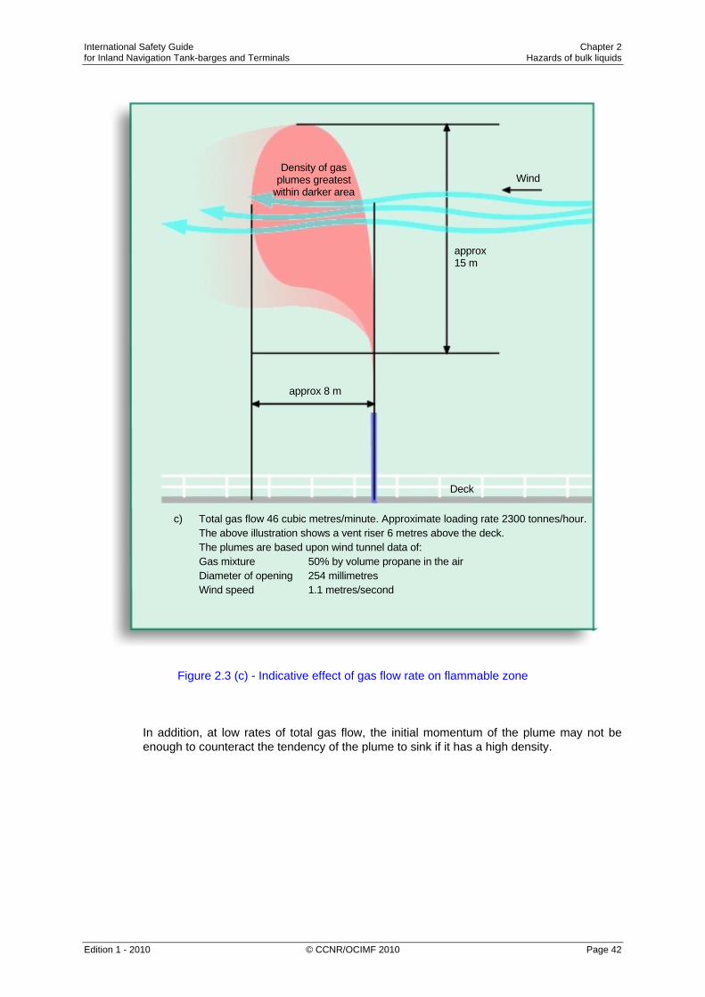
International Safety Guide Chapter 2 for Inland Navigation Tank-barges and Terminals Hazards of bulk liquids
Edition 1 - 2010 © CCNR/OCIMF 2010 Page 42
Figure 2.3 (c) - Indicative effect of gas flow rate on flammable zone
In addition, at low rates of total gas flow, the initial momentum of the plume may not be enough to counteract the tendency of the plume to sink if it has a high density.
Density of gasplumes greatest
within darker area
approx 15 m
approx 8 m
Wind
Deck
c) Total gas flow 46 cubic metres/minute. Approximate loading rate 2300 tonnes/hour. The above illustration shows a vent riser 6 metres above the deck. The plumes are based upon wind tunnel data of: Gas mixture 50% by volume propane in the air Diameter of opening 254 millimetres Wind speed 1.1 metres/second

International Safety Guide Chapter 2 for Inland Navigation Tank-barges and Terminals Hazards of bulk liquids
Edition 1 - 2010 © CCNR/OCIMF 2010 Page 43
The results of the interaction of these different processes at low wind speed are illustrated in Figure 2.3. The gas mixture used in obtaining these diagrams was 50% by volume propane and 50% by volume air. At the lowest flow rate (Figure 2.3 (a)) the density effect predominates and the gas sinks back towards the deck. At the highest flow rate (Figure 2.3 (c)) mixing is far more efficient and there is no tendency for the plume to sink.
2.5.4.4 Concentration of Product Gas
With a constant total rate of flow of gas, changes in product concentration have two effects. The rate of emission of hydrocarbon gas increases in proportion to the concentration so that, other things being equal, the extent of the flammable zone increases. Also, the initial density of the gas mixture as it issues from the opening becomes greater so that there is a greater tendency for the plume to sink. At low concentrations, therefore, a flammable zone similar in outline to that shown in Figure 2.3 (c) is to be expected, but it is likely to be small because of the relatively small amount of hydrocarbon gas. As the concentration increases, the flammable zone tends to assume such shapes as depicted in Figures 2.3 (b) and 2.3 (a) as the increasing density exerts its influence. In addition, the overall size of the zone becomes greater due to the greater rate of emission of hydrocarbon gas.
2.5.4.5 Cross-Sectional Area of the Opening
The area of the opening through which the product gas/air mixture issues determines, for a given volumetric rate of flow, the linear flow velocity and hence the efficiency of the mixing of the plume with the atmosphere. Effects of this kind occur, for example, in gas freeing. If fixed turbo-blower fans are used, the mixture is usually vented through a standpipe with a cross-sectional area small enough to give a high velocity and to encourage dispersion in the atmosphere. When using small portable blowers, which normally have to be operated against a low back pressure, it is usual to exhaust the gas through an open tank hatch. The outflow velocity is then very low with the outlet close to the deck; circumstances that encourage the gas to remain close to the deck.
2.5.4.6 The Design of the Vent Outlet The design and position of a vent outlet must comply with current applicable (inter)national legislation. In certain operations, such as gas freeing, vapour may be vented from the tank through apertures other than these designated tank vents.
2.5.4.7 Position of the Vent Outlet
If vent outlets are situated near structures such as accommodation blocks, the shape of the flammable zone is influenced by turbulence produced in the air as it passes over the superstructure. A diagram illustrating the kind of eddies formed is given in Figure 2.4. This shows how, on the upwind side, there are downward eddies below a level indicated by the line X-X and how, above and in the lee of the structure, there is a tendency for turbulent air to form eddies close to the structure. These movements can adversely affect the efficient dispersion of product gas.

International Safety Guide Chapter 2 for Inland Navigation Tank-barges and Terminals Hazards of bulk liquids
Edition 1 - 2010 © CCNR/OCIMF 2010 Page 44
If the exit velocity from an opening near a structure is high, it can overcome the influence of eddies. For example, Figure 2.5 (a) shows the flammable zone from a tank opening situated only about 1.5 metres upwind of an accommodation block; the plume is almost vertical and only just touches the accommodation block. However, a somewhat lower rate of venting would have resulted in serious impingement of the zone upon the accommodation block. Figure 2.5 (b) illustrates the effect of an additional opening which doubles the amount of gas released. Partly as the result of eddies and partly due to the denser combined plume, the flammable zone is in close contact with the top of the accommodation block.
Figure 2.4 - Typical pattern of airflow around an accommodation block

International Safety Guide Chapter 2 for Inland Navigation Tank-barges and Terminals Hazards of bulk liquids
Edition 1 - 2010 © CCNR/OCIMF 2010 Page 45
2.5.5 Minimising Hazards from Vented Gas
The objective of venting arrangements and their operational control is to minimise the possibilities of flammable gas concentrations entering enclosed spaces containing sources of ignition, or reaching deck areas where, notwithstanding all other precautions, there might be a source of ignition. In previous Sections, means have been described of promoting rapid dispersion of gas and minimising its tendency to sink to the deck. Although this Section is concerned with flammability, the same principles apply to dispersion of gas down to concentrations that are safe to personnel. The following conditions should be taken into account for any operation where flammable mixtures are displaced to the atmosphere or where mixtures are displaced which could become flammable on dilution with air, such as on inerted tankers: • An unimpeded vertical discharge at a high efflux velocity. • Positioning the outlet sufficiently high above the deck. • Placing the outlet at an adequate distance from the superstructure and other enclosed
spaces. When using a vent outlet of fixed diameter, usually designed for 125% of the maximum cargo loading rate, the efflux velocity will drop at lower loading rates. Vent outlets with automatically variable areas (high velocity vent valves) may be fitted to maintain a high efflux velocity under all loading conditions.

International Safety Guide Chapter 2 for Inland Navigation Tank-barges and Terminals Hazards of bulk liquids
Edition 1 - 2010 © CCNR/OCIMF 2010 Page 46
Figure 2.5 - Flammable zone from apertures near an accommodation block

International Safety Guide Chapter 2 for Inland Navigation Tank-barges and Terminals Hazards of bulk liquids
Edition 1 - 2010 © CCNR/OCIMF 2010 Page 47
The venting arrangements should always be used during cargo loading operations and during any ballasting into non-gas free cargo tanks. When gas freeing by fixed mechanical blower, or purging with inert gas either by displacement or dilution through designated outlets, sufficiently high efflux velocities should be maintained to ensure rapid gas dispersion in any conditions. When gas freeing by portable blowers, it may be necessary to open a tank hatch lid to act as a gas outlet, with a resulting low gas outlet velocity. Vigilance is then required to ensure that gas does not accumulate on deck. If an inerted tank is being gas freed through the open hatch, there may be localised areas where the atmosphere is deficient in oxygen. If practicable, it is preferable to gas free through a small diameter opening, such as a tank cleaning opening, with a temporary standpipe rigged. In all operations where gas is being vented, great vigilance should be exercised, especially under adverse conditions (e.g. if there is little or no wind). Under such conditions, it may be prudent to stop operations until conditions improve.
2.5.6 N/A
2.6 N/A 2.7 The Hazards Associated with the Handling, Storage and Carriage of Residual
Products 2.7.1 General
The first part of this Section deals with the flammability hazards associated with residual fuel oils and provides information on flashpoint and vapour composition measurement, together with recommended precautionary procedures to be adopted when handling, storing or carrying residual fuel oils. It should be noted that this guidance refers only to residual fuel oils and not to distillate fuels. Reference should be made to Section 11.8.2 for precautions to be taken when measuring and sampling in non-inerted tanks when there is any possibility that a flammable gas/air mixture may be present. The last part of this Section refers to the hydrogen sulphide hazard associated with fuel oil (see also Section 2.3.6).
2.7.2 Nature of Hazard Residual fuel oils are capable of producing light hydrocarbons in the tank headspace, such that the vapour composition may be near to or within the flammable range. This can occur even when the storage temperature is well below the measured flashpoint. This is not normally a function of the origin or manufacturing process of the fuel, although fuels containing cracked residues may show a greater tendency to generate light hydrocarbons.

International Safety Guide Chapter 2 for Inland Navigation Tank-barges and Terminals Hazards of bulk liquids
Edition 1 - 2010 © CCNR/OCIMF 2010 Page 48
Although light hydrocarbons may be present in the headspaces of residual fuel oil tanks, the risk associated with them is small unless the atmosphere is within the flammable range and an ignition source is present. In such a case, an incident could result. It is therefore recommended that residual fuel oil headspaces be regarded as being potentially flammable.
2.7.3 Flashpoint and Headspace Flammability Measurement 2.7.3.1 Flashpoint
Fuel oils are classified for their safety in storage, handling and transportation by reference to their closed cup flashpoint (see also Section 1.2.5). However, information on the relationship between the calculated flammability of a headspace atmosphere and the measured flashpoint of the residual fuel oil has shown that there is no fixed correlation. A flammable atmosphere can therefore be produced in a tank headspace even when a residual fuel oil is stored at a temperature below its flashpoint.
2.7.3.2 Headspace Flammability Traditionally, gas detectors such as explosimeters have been used to check that enclosed spaces are gas free, and they are entirely suited to this purpose (see Section 2.4.3). They have also been used to measure the “flammability” of headspaces in terms of percentage of the Lower Explosive Limit (LEL). Such detectors rely on a calibration carried out normally on a single hydrocarbon, such as methane, which may have LEL characteristics that are far removed from the hydrocarbons actually present in the headspace. When using an explosimeter to assess the degree of hazard in non-inerted residual fuel oil tank headspaces, it is recommended that the instrument is calibrated with a pentane/air or hexane/air mixture. This will result in a more conservative estimate of the flammability, but the readings should still not be regarded as providing a precise measurement of the vapour space condition. When taking measurements, the manufacturer’s operating instructions for the instrument should be closely followed and the instrument’s calibration should be checked frequently as oxidation catalyst detectors (pellistors) are likely to be susceptible to poisoning when exposed to residual fuel oil vapours. For information on poisoning of pellistors, see Section 2.4.3.2. In view of the problems associated with obtaining accurate measurements of the flammability of residual fuel tank headspaces using readily available portable equipment, the measured % LEL only ranks fuels broadly in terms of relative hazard. Care should be exercised therefore in interpretation of the figures obtained by such gas detectors.
2.7.4 Precautionary Measures 2.7.4.1 Storage and Handling Temperatures
When carried as fuel, temperatures of the residual fuel oil in the fuel system should conform to relevant codes of practice at all times and excessive local heating should be avoided.

International Safety Guide Chapter 2 for Inland Navigation Tank-barges and Terminals Hazards of bulk liquids
Edition 1 - 2010 © CCNR/OCIMF 2010 Page 49
2.7.4.2 Filling and Venting
When tanks are being filled, tank headspace gas will be displaced through vent pipes. Particular care should be taken to ensure that flame screens or traps are in good condition and that there are no ignition sources in the area immediately surrounding the venting system. When filling empty or near empty tanks, the heating coils should be shut down and cool. Fuel oil contacting hot, exposed heating coils could possibly lead to the rapid generation of a flammable atmosphere.
2.7.4.3 Headspace Classification All residual fuel oil tank headspaces should be classified as hazardous and suitable precautions taken. Electrical equipment within the space must meet the appropriate safety standards.
2.7.4.4 Hazard Reduction
The flammability of the headspace of residual fuel oil tanks should be monitored regularly. If a measured value in excess of recommended levels is detected (IMO Resolution A.565(14) refers to a level in excess of 50% LEL), action should be taken to reduce the vapour concentration by purging the headspace with low pressure air. Gases should be vented to a safe area with no ignition sources in the vicinity of the outlet. On completion of venting, gas concentrations within the tank should continue to be monitored and further venting undertaken if necessary. When residual fuel oil is carried as cargo on board tankers fitted with inert gas, it is recommended that the inert gas is utilised and that the headspace is maintained in an inert condition.
2.7.4.5 Ullaging and Sampling All operations should be conducted such as to take due care to avoid the hazards associated with static electrical charges (see Section 11.8.2).
2.7.5 Hydrogen Sulphide Hazard in Residual Fuel Oils Bunker fuels containing high H2S concentrations may be supplied without advice being passed to the tanker beforehand. Tanker’s personnel should always be alert to the possible presence of H2S in bunker fuel and be prepared to take suitable precautions if it is present. Before loading bunkers, the tanker should communicate with the supplier to ascertain whether the fuel to be loaded is likely to have any H2S content. The design of bunker tank vents and their location makes managing the exposure to personnel more difficult, as closed loading and venting cannot usually be implemented.

International Safety Guide Chapter 2 for Inland Navigation Tank-barges and Terminals Hazards of bulk liquids
Edition 1 - 2010 © CCNR/OCIMF 2010 Page 50
If bunkering with fuel containing H2S above the TLV-TWA cannot be avoided, procedures should be in place to monitor and control the access of personnel to exposure areas. Ventilation to lower the concentration of vapour in the ullage space and in specific areas where vapours may accumulate should be carried out as soon as practicable. Even after the tank has been ventilated to reduce the concentration to an acceptable level, subsequent transfer, heating and agitation of the fuel within a tank may cause the concentration to reappear. Periodic monitoring of the concentration of H2S should be continued until the bunker tank is refilled with a fuel oil not containing H2S.

International Safety Guide Chapter 3 for Inland Navigation Tank-barges and Terminals Static electricity
Edition 1 - 2010 © CCNR/OCIMF 2010 Page 51
Chapter 3
STATIC ELECTRICITY
This Chapter describes hazards associated with the generation of static electricity during the loading and discharging of cargo and during tank cleaning, dipping, ullaging and sampling. Section 3.1 introduces some basic principles of electrostatics in order to explain how objects become charged and to describe the effect of those charges on other objects in close surroundings. The risks presented by static electricity discharges occur where a flammable atmosphere is likely to be present. The main precaution for tankers against electrostatic risks is to conduct operations with the cargo tanks protected by inert gas. Section 3.2 describes, in general terms, precautions against electrostatic hazards in tanks that are not protected by inert gas; these are discussed in more detail in Chapter 11 (Shipboard Operations). Section 3.3 considers other likely sources of electrostatic hazards in tanker and terminal operations.
3.1 Principles of Electrostatics 3.1.1 Summary
Static electricity presents fire and explosion hazards during the handling of flammable liquids and during other tanker operations such as tank cleaning, dipping, ullaging and sampling. Certain operations can give rise to accumulations of electric charge that may be released suddenly in electrostatic discharges with sufficient energy to ignite flammable product gas/air mixtures. There is, of course, no risk of ignition unless a flammable mixture is present. There are three basic stages leading up to a potential electrostatic hazard: • Charge separation. • Charge accumulation. • Electrostatic discharge. All three of these stages are necessary for an electrostatic ignition of a flammable atmosphere. Electrostatic discharges can occur as a result of accumulations of charge on: • Liquid or solid non-conductors, for example a static accumulator oil (such as
kerosene) pumped into a tank, or a polypropylene rope. • Electrically insulated liquid or solid conductors, for example mists, sprays or
particulate suspensions in air, or an unbonded metal rod hanging on the end of a rope. The principles of electrostatic hazards and the precautions to be taken to manage the risks are described fully below.
International Safety Guide Chapter 3 for Inland Navigation Tank-barges and Terminals Static electricity
Edition 1 - 2010 © CCNR/OCIMF 2010 Page 52
3.1.2 Charge Separation
Whenever two dissimilar materials come into contact, charge separation occurs at the interface. The interface may be between two solids, between a solid and a liquid or between two immiscible liquids. At the interface, a charge of one sign (say positive) moves from material A to material B so that materials A and B become respectively negatively and positively charged. While the materials stay in contact and immobile relative to one another, the charges are extremely close together. The voltage difference between the charges of opposite sign is then very small, and no hazard exists. However, when the materials move relative to one another, the charges can be separated and the voltage difference increased. The charges can be separated by many processes. For example: • The flow of liquid product through pipes. • Flow through fine filters (less than 150 microns) that have the ability to charge
products to a very high level, as a result of all the product being brought into intimate contact with the filter surface where charge separation occurs.
• Contaminants, such as water droplets, rust or other particles, moving relative to product as a result of turbulence in the product as it flows through pipes.
• The settling of a solid or an immiscible liquid through a liquid (e.g. water, rust or other particles through the product). This process may continue for up to 30 minutes after completion of loading into a tank.
• Gas bubbles rising up through a liquid (e.g. air, inert gas introduced into a tank by the blowing of cargo lines or vapour from the liquid itself, released when pressure is dropped). This process may also continue for up to 30 minutes after completion of loading.
• Turbulence and splashing in the early stages of loading product into an empty tank. This is a problem in the liquid and in the mist that can form above the liquid.
• The ejection of particles or droplets from a nozzle (e.g. during steaming operations or injection of inert gas).
• The splashing or agitation of a liquid against a solid surface (e.g. water washing operations or the initial stages of filling a tank with product).
• The vigorous rubbing together and subsequent separation of certain synthetic polymers (e.g. the sliding of a polypropylene rope through gloved hands).
When the charges are separated, a large voltage difference can develop between them. A voltage distribution is also set up throughout the neighbouring space and this is known as an electrostatic field. Examples of this are: • The charge on a charged liquid in a tank produces an electrostatic field throughout the
tank, both in the liquid and in the ullage space. • The charge on a water mist formed by tank washing produces an electrostatic field
throughout the tank.

International Safety Guide Chapter 3 for Inland Navigation Tank-barges and Terminals Static electricity
Edition 1 - 2010 © CCNR/OCIMF 2010 Page 53
If an uncharged conductor is present in an electrostatic field, it has approximately the same voltage as the region it occupies. Furthermore, the field causes a movement of charge within the conductor; a charge of one sign is attracted by the field to one end of the conductor and an equal charge of the opposite sign is left at the opposite end. Charges separated in this way are known as ‘induced charges’ and, as long as they are kept separate by the presence of the field, they are capable of contributing to an electrostatic discharge.
3.1.3 Charge Accumulation
Charges that have been separated attempt to recombine and to neutralise each other. This process is known as ‘charge relaxation’. If one or both of the separated materials carrying charge is a very poor electrical conductor, recombination is impeded and the material retains or accumulates the charge upon it. The period of time for which the charge is retained is characterised by the relaxation time of the material, which is related to its conductivity; the lower the conductivity, the greater the relaxation time. If a material has a comparatively high conductivity, the recombination of charges is very rapid and can counteract the separation process, and consequently little or no static electricity accumulates on the material. Such a highly conductive material can only retain or accumulate charge if it is insulated by means of a poor conductor, and the rate of loss of charge is then dependent upon the relaxation time of this lesser conducting material. The important factors governing relaxation are therefore the electrical conductivities of the separated materials, of other conductors nearby, such as tanker’s structure, and of any additional materials that may be interposed between them after their separation.
3.1.4 Electrostatic Discharge
Electrostatic discharge occurs when the electrostatic field becomes too strong and the electrical resistance of an insulating material suddenly breaks down. When breakdown occurs, the gradual flow and charge recombination associated with relaxation is replaced by sudden flow recombination that generates intense local heating (e.g. a spark) that can be a source of ignition if it occurs in a flammable atmosphere. Although all insulating media can be affected by breakdowns and electrostatic discharges, the main concern for tanker operations is the prevention of discharges in air or vapour, so as to avoid sources of ignition. Electrostatic fields in tanks or compartments are not uniform because of tank shape and the presence of conductive internal protrusions, such as probes and structure. The field strength is enhanced around these protrusions and, consequently, that is where discharges generally occur. A discharge may occur between a protrusion and an insulated conductor or solely between a conductive protrusion and the space in its vicinity, without reaching another object.
3.1.4.1 Types of Discharge
Electrostatic discharge can take the form of a ‘corona’, a ‘brush discharge’, a ‘spark’ or a ‘propagating brush discharge’, as described below: Corona is a diffuse discharge from a single sharp conductor that slowly releases some of the available energy. Generally, corona on its own is incapable of igniting a gas.

International Safety Guide Chapter 3 for Inland Navigation Tank-barges and Terminals Static electricity
Edition 1 - 2010 © CCNR/OCIMF 2010 Page 54
Brush Discharge is a diffuse discharge from a highly charged non-conductive object to a single blunt conductor that is more rapid than corona and releases more energy. It is possible for a brush discharge to ignite gases and vapours. Examples of a brush discharge are: • Between a conductive sampling apparatus lowered into a tank and the surface of a
charged liquid. • Between a conductive protrusion (e.g. fixed tank washing machine) or structural
member and a charged liquid being loaded at a high rate. Spark is an almost instantaneous discharge between two conductors where almost all of the energy in the electrostatic field is converted into heat that is available to ignite a flammable atmosphere. Examples of sparks are: • Between an unearthed conductive object floating on the surface of a charged liquid
and the adjacent tank structure. • Between unearthed conductive equipment suspended in a tank and the adjacent tank
structure. • Between conductive tools or materials left behind after maintenance when insulated
by a rag or piece of lagging.
Sparks can be incendive if various requirements are met. These include: • A discharge gap short enough to allow the discharge to take place with the voltage
difference present, but not so short that any resulting flame is quenched. • Sufficient electrical energy to supply the minimum amount of energy to initiate
combustion. Propagating Brush Discharge is a rapid, high energy discharge from a sheet of material of high resistivity and high dielectric strength with the two surfaces highly charged but of opposite polarity. The discharge is initiated by an electrical connection (short circuit) between the two surfaces. The bipolar sheet can be in ‘free space’ or, as is more normal, have one surface in intimate contact with a conducting material (normally earthed).
The short circuit can be achieved: • By piercing the surface (mechanically or by an electrical break-through). • By approaching both surfaces simultaneously with two electrodes electrically
connected. • When one of the surfaces is earthed, by touching the other surface with an earthed
conductor. A propagating brush discharge can be highly energetic (1 joule or more) and so will readily ignite a flammable mixture. Scientific studies have shown that epoxy coatings greater than 2 mm thick on tanks, filling pipes and fittings may give rise to conditions whereby there is a possibility of a propagating brush discharge. In these cases, there would be a need to seek expert advice on requirements to explicitly earth the cargo. However, on most tankers, the thickness of epoxy coatings is not generally greater than 2 mm.

International Safety Guide Chapter 3 for Inland Navigation Tank-barges and Terminals Static electricity
Edition 1 - 2010 © CCNR/OCIMF 2010 Page 55
3.1.4.2 Conductivity
Materials and liquid products that are handled by tankers and terminals are classified as being non-conductive, semi-conductive (in most electrostatic standards the term ‘dissipative’ is now preferred to ‘semi-conductive’) or conductive. Non-Conductive Materials (or Non-Conductors) These materials have such low conductivities that once they have received a charge they retain it for a very long period. Non-conductors can prevent the loss of charge from conductors by acting as insulators. Charged non-conductors are of concern because they can generate incendive brush discharges to nearby earthed conductors and because they can transfer a charge to, or induce a charge on, neighbouring insulated conductors that may then give rise to sparks. Liquids are considered to be non-conductors when they have conductivities less than 50 pS/m (pico Siemens/metre). Such liquids are often referred to as static accumulators. Reference should be made to a product’s (M)SDS to ascertain its conductivity. The solid non-conductors include plastics, such as polypropylene, PVC, nylon and many types of rubber. They can become more conductive if their surfaces are contaminated with dirt or moisture. (Precautions to be taken when loading static accumulator oils are addressed in Section 11.1.7.) Semi-Conductive Materials (or Dissipative Materials or Intermediate Conductors) The liquids in this intermediate category have conductivities exceeding 50pS/m and, along with conductive liquids, are often known as static non-accumulators. The solids in this intermediate category generally include such materials as wood, cork, sisal and naturally occurring organic substances. They owe their conductivity to their ready absorption of water and they become more conductive as their surfaces are contaminated by moisture and dirt. However, when new or thoroughly cleaned and dried, their conductivities can be sufficiently low to bring them into the non-conductive range. If materials in the intermediate conductivity group are not insulated from earth, their conductivities are high enough to prevent accumulation of an electrostatic charge. However, their conductivities are normally low enough to inhibit production of energetic sparks. For materials with intermediate conductivities, the risk of electrostatic discharge is small, particularly if practices in this Guide are adhered to, and the chance of their being incendive is even smaller. However, caution should still be exercised when dealing with intermediate conductors because their conductivities are dependent upon many factors and their actual conductivity is not known. Conductive Materials In the case of solids, these are metals and, in the case of liquids, the whole range of aqueous solutions, including sea water. The human body, consisting of about 60% water, is effectively a liquid conductor. Many alcohols are conductive liquids.

International Safety Guide Chapter 3 for Inland Navigation Tank-barges and Terminals Static electricity
Edition 1 - 2010 © CCNR/OCIMF 2010 Page 56
The important property of conductors is that they are incapable of holding a charge unless insulated, but also that, if they are insulated, charged and an opportunity for an electrical discharge occurs, all the charge available is almost instantaneously released into the potentially incendive discharge. Table 3.1 provides information on the typical conductivity value and classification for a range of products:
Product Typical Conductivity (picoSiemens/metre)
Classification
Non-Conductive
Xylene 0.1 Accumulator
Gasoline (straight run) 0.1 to 1 Accumulator
Diesel (ultra-low sulphur) 0.1 to 2 Accumulator
Lube oil (base) 0.1 to 1,000* Accumulator
Commercial jet fuel 0.2 to 50 Accumulator
Toluene 1 Accumulator
Kerosene 1 to 50 Accumulator
Diesel 1 to 100* Accumulator
Cyclohexane <2 Accumulator
Motor gasoline 10 to 300* Accumulator
Semi-Conductive
Fuel with anti-static additive 50 to 300 Non-accumulator
Heavy black fuel oils 50 to 1,000 Non-accumulator
Conductive crude >1,000 Non-accumulator
Bitumen >1,000 Non-accumulator
Alcohols 100,000 Non-accumulator
Ketones 100,000 Non-accumulator
Conductive
Distilled water 1,000,000,000 Non-accumulator
Water 100,000,000,000 Non-accumulator
Table 3.1 - Typical conductivity of products

International Safety Guide Chapter 3 for Inland Navigation Tank-barges and Terminals Static electricity
Edition 1 - 2010 © CCNR/OCIMF 2010 Page 57
3.1.5 Electrostatic Properties of Gases and Mists
Under normal conditions, gases are highly insulating and this has important implications with respect to mists and particulate suspensions in air and other gases. Charged mists are formed during the ejection of liquid from a nozzle, for example: • Products entering an empty tank at high velocity. • Wet steam condensing. • Water from tank washing machines.
Although the liquid, for example water, may have a very high conductivity, the relaxation of the charge on the droplets is hindered by the insulating properties of the surrounding gas. Fine particles present in inert flue gas, or created during discharge of pressurised liquid carbon dioxide, are frequently charged. The gradual charge relaxation, which does occur, is the result of the settling of the particles or droplets and, if the field strength is high, of corona discharge at sharp protrusions. Under certain circumstances, discharges with sufficient energy to ignite product gas/air mixtures can occur. See also Section 3.3.4.
3.2 General Precautions Against Electrostatic Hazards 3.2.1 Overview
Whenever a flammable atmosphere could potentially be present, the following measures must be taken to prevent electrostatic hazards: • The bonding of metal objects to the metal structure of the tanker to eliminate the risk
of spark discharges between metal objects that might be electrically insulated. This includes metallic components of any equipment used for dipping, ullaging and sampling.
• The removal from tanks or other hazardous areas of any loose conductive objects that cannot be bonded.
• Restricting the linear velocity of the cargo to a maximum of 1 metre per second at the individual tank inlets during the initial stages of loading, i.e. until: a) the filling pipe and any other structure on the base of the tank has been
submerged to twice the filling pipe diameter in order that all splashing and surface turbulence has ceased and
b) any water collected in the pipeline has been cleared. It is necessary to load at this restricted rate for a period of 30 minutes or until two pipeline volumes (i.e. from shore tank to ship’s tank) have been loaded into the tank, whichever is the lesser.

International Safety Guide Chapter 3 for Inland Navigation Tank-barges and Terminals Static electricity
Edition 1 - 2010 © CCNR/OCIMF 2010 Page 58
Number of tanks open – velocity in m3/h
Diameter 1 2 3 4 5 6 7 8
6'' / 150 mm 65 130 200 260 325 390 450 520
8'' / 200 mm 120 240 350 460 580 700 820 -
10'' / 250 mm 180 360 540 720 910 - - -
12'' / 300 mm 260 520 780 - - - - -
Table 3.2 – Loading Rates Equivalent to Flow Velocity of 1 metre/second (Initial Stage of Loading)
Also see chapter 7.3.3.2 and 11.1.7.3
• Continuing to restrict the product flow to a maximum of 1 m/s at the tank inlet for the whole operation unless the product is ‘clean’. A ‘clean’ product, within this context, is defined as one which contains less than 0.5% by volume of free water or other immiscible liquid and less than 10 mg/l of suspended solids1.
• Avoiding splash filling by employing bottom entry using a fill pipe terminating close to the bottom of the tank.
The following additional precautions should be taken against static electricity during ullaging, dipping, gauging or sampling of static accumulator products: • Banning the use of all metallic equipment for dipping, ullaging and sampling during
loading and for 30 minutes after completion of loading. After the 30 minute waiting period, metallic equipment may be used for dipping, ullaging and sampling, but it must be effectively bonded and securely earthed to the structure of the tanker before it is introduced into the tank, and must remain earthed until after removal.
• Banning the use of all non-metallic containers of more than 1 litre capacity for dipping, ullaging and sampling during loading and for 30 minutes after completion of loading.
Non-metallic containers of less than 1 litre capacity may be used for sampling in tanks at any time, provided that they have no conducting components and that they are not rubbed prior to sampling. Cleaning with a high conductivity proprietary cleaner, a solvent such as 70:30 IPA:toluene mix, or soapy water, is recommended to reduce charge generation. To prevent charging, the container should not be rubbed dry after washing.
1 CENELEC Technical Report CLC/TR 50404, “Electrostatics - Code of Practice for the Avoidance of Hazards Due to Static
Electricity, June 2003.

International Safety Guide Chapter 3 for Inland Navigation Tank-barges and Terminals Static electricity
Edition 1 - 2010 © CCNR/OCIMF 2010 Page 59
Operations carried out through a correctly designed and installed sounding pipe are permissible at any time. It is not possible for any significant charge to accumulate on the surface of the liquid within the sounding pipe and therefore no waiting time is required. However, the precautions to be observed against introducing charged objects into a tank still apply and if metallic equipment is used it should be bonded before being inserted into the sounding pipe. Detailed guidance on precautions to be taken during ullaging, dipping and sampling of static accumulator oils is given in Section 11.8.2.3. These precautions should be rigidly adhered to in order to avoid hazards associated with the accumulation of an electrical charge on the cargo.
3.2.2 Bonding The most important countermeasure that must be taken to prevent an electrostatic hazard is to bond all metallic objects together to eliminate the risk of discharges between objects that might be charged and electrically insulated. To avoid discharges from conductors to earth, it is normal practice to include bonding to earth (‘earthing’ or ‘grounding’). On tankers, bonding to earth is effectively accomplished by connecting metallic objects to the metal structure of the tanker, which is naturally earthed through the water. Some examples of objects which might be electrically insulated in hazardous situations and which must therefore be bonded are: • Ship/shore hose couplings and flanges, except for the insulating flange or single
length of non-conducting hose required to provide electrical isolation between the ship and shore. (See Section 17.5.)
• Portable tank washing machines. • Manual ullaging and sampling equipment with conducting components. • The float of a permanently fitted ullaging device if its design does not provide an
earthing path through the metal tape. The best method of ensuring bonding and earthing will usually be a metallic connection between the conductors. Alternative means of bonding are available and have proved effective in some applications, for example semi-conductive (dissipative) pipes and ‘O’ rings, rather than embedded metallic layers, for GRP pipes and their metal couplings. Any earthing or bonding links used as a safeguard against the hazards of static electricity associated with portable equipment must be connected whenever the equipment is set up and not disconnected until after the equipment is no longer in use.
International Safety Guide Chapter 3 for Inland Navigation Tank-barges and Terminals Static electricity
Edition 1 - 2010 © CCNR/OCIMF 2010 Page 60
3.2.3 Avoiding Loose Conductive Objects
Certain objects may be insulated during tanker operations, for example: • A metal object, such as a can, floating in a static accumulating liquid. • A loose metal object while it is falling in a tank during washing operations. • A metallic tool, lying on a piece of old lagging, left behind after maintenance. Every effort should be made to ensure that such objects are removed from the tank since there is evidently no possibility of deliberately bonding them. This necessitates careful inspection of tanks, particularly after shipyard repairs.
3.3 Other Sources of Electrostatic Hazards 3.3.1 Filters
Three classifications of filter may be used as follows: Coarse (greater than or equal to 150 microns). These do not generate a significant amount of charge, and require no additional precautions provided that they are kept clean.
Fine (less than 150 microns, greater than 30 microns). These can generate a significant amount of charge and therefore require sufficient time for the charge to relax before the liquid reaches the tank. It is essential that the liquid spends a minimum of 30 seconds (residence time) in the piping downstream of the filter. Flow velocity should be controlled to ensure that this residence time requirement is met.
Microfine (less than or equal to 30 microns). To allow sufficient time for the charge to relax, the residence time after passing through microfine filters must be a minimum of 100 seconds before the product enters the tank. Flow velocity should be adjusted accordingly
3.3.2 Fixed Equipment in Cargo Tanks
A metal probe, remote from any other tank structure but near a highly charged liquid surface, will have a strong electrostatic field at the probe tip. Protrusions of this type may be associated with equipment mounted from the top of a tank, such as fixed washing machines or high level alarms. During the loading of static accumulator oils, this strong electrostatic field may cause electrostatic discharges to the approaching liquid surface. Metal probes of the type described above can be avoided by installing the equipment adjacent to a bulkhead or other tank structure to reduce the electrostatic field at the probe tip. Alternatively, a support can be added running from the lower end of the probe downward to the tank structure below, so that the rising liquid meets the support at earth potential rather than the insulated tip of a probe. Another possible solution, in some cases, is to construct the probe-like device entirely of a non-conductive material. These measures are not necessary if the tanker is limited to conductive products or if the tanks are inerted.

International Safety Guide Chapter 3 for Inland Navigation Tank-barges and Terminals Static electricity
Edition 1 - 2010 © CCNR/OCIMF 2010 Page 61
3.3.3 Free Fall in Tanks
Loading or ballasting over the top (overall) delivers charged liquid to a tank in such a manner that it can break up into small droplets and splash into the tank. This may produce a charged mist as well as an increase in the product gas concentration in the tank. Restrictions upon loading or ballasting overall are given in Section 11.1.12.
3.3.4 Water Mists
The spraying of water into tanks, for instance during water washing, gives rise to electrostatically charged mist. This mist is uniformly spread throughout the tank being washed. The electrostatic levels vary widely from tank to tank, both in magnitude and in sign. When washing is started in a dirty tank, the charge in the mist is initially negative, reaches a maximum negative value, then goes back through zero and finally rises towards a positive equilibrium value. It has been found that, among the many variables affecting the level and polarity of charging, the characteristics of the wash water and the degree of cleanliness of the tank have the most significant influence. The electrostatic charging characteristics of the water are altered by re-circulation or by the addition of tank cleaning chemicals, either of which may cause very high electrostatic potentials in the mist. Potentials are higher in large tanks than in small ones. The size and number of washing machines in a tank affect the rate of change of charge, but they have little effect on the final equilibrium value. The charged mist droplets created in the tank during washing give rise to an electrostatic field, which is characterised by a distribution of potential (voltage) throughout the tank space. The bulkheads and structure are at earth (zero) potential and the space potential increases with distance from these surfaces and is highest at points furthest from them. The field strength, or voltage gradient, in the space is greatest near the tank bulkheads and structure, more especially where there are protrusions into the tank. If the field strength is high enough, electric breakdown occurs into the space, giving rise to a corona. Because protrusions cause concentrations of field strength, a corona occurs preferentially from such points. A corona injects a charge of the opposite sign into the mist and is believed to be one of the main processes limiting the amount of charge in the mist to an equilibrium value. The corona discharges produced during tank washing are not strong enough to ignite the hydrocarbon gas/air mixtures that may be present. Under certain circumstances, discharges with sufficient energy to ignite product gas/air mixtures can occur from unearthed conducting objects already within, or introduced into, a tank filled with charged mist. Examples of such unearthed conductors are a metal sounding rod suspended on a rope or a piece of metal falling through the tank space. An unearthed conductor within a tank can acquire a high potential, primarily by induction, when it comes near an earthed object or structure, particularly if the latter is in the form of a protrusion. The unearthed conductor may then discharge to earth giving rise to a spark capable of igniting a flammable product gas/air mixture.

International Safety Guide Chapter 3 for Inland Navigation Tank-barges and Terminals Static electricity
Edition 1 - 2010 © CCNR/OCIMF 2010 Page 62
The processes by which unearthed conductors give rise to ignitions in a mist are fairly complex, and a number of conditions must be satisfied simultaneously before an ignition can occur. These conditions include the size of the object, its trajectory, the electrostatic level in the tank and the geometrical configuration where the discharge takes place. As well as solid unearthed conducting objects, an isolated slug of water produced by the washing process may similarly act as a spark promoter and cause an ignition. Experiments have shown that high capacity, single nozzle, fixed washing machines can produce water slugs which, owing to their size, trajectory and duration before breaking up, may satisfy the criteria for producing incendive discharges. However, there is no evidence of water slugs capable of producing incendive discharges being produced by portable types of washing machine. This can be explained by the fact that, if the jet is initially fine, the length of slugs that are produced are relatively small so that they have a small capacitance and do not readily produce incendive discharges. Following extensive experimental investigations and using the results of long-term experience, the tanker industry has drawn up the tank washing guidelines set out in Section 11.3. These guidelines are aimed at preventing excessive charge generation in mists and at controlling the introduction of unearthed conducting objects when there is charged mist in the tank.
3.3.5 Inert Gas
Small particulate matter carried in inert gas can be electrostatically charged. The charge separation originates in the combustion process and the charged particles are capable of being carried through the scrubber, fan and distribution pipes into the cargo tanks. The electrostatic charge carried by the inert gas is usually small, but levels of charge have been observed well above those encountered with the water mists formed during washing. Because the tanks are normally in an inert condition, the possibility of an electrostatic ignition has to be considered only if it is necessary to inert a tank which already contains a flammable atmosphere or if a tank already inerted is likely to become flammable because the oxygen content rises as a result of ingress of air. Precautions are then required during dipping, ullaging and sampling. (See Section 11.8.3.).
3.3.6 Discharge of Carbon Dioxide
During the discharge of pressurised liquid carbon dioxide, the rapid cooling which takes place can result in the formation of particles of solid carbon dioxide that become charged on impact and contact with the nozzle. The charge can be significant with the potential for incendive sparks. Liquefied carbon dioxide should not be used for inerting, or injected for any other reason into cargo tanks or pump rooms that may contain flammable gas mixtures.

International Safety Guide Chapter 3 for Inland Navigation Tank-barges and Terminals Static electricity
Edition 1 - 2010 © CCNR/OCIMF 2010 Page 63
3.3.7 Clothing and Footwear
People who are insulated from earth by their footwear or the surface on which they are standing can become electrostatically charged. This charge can arise from physical separation of insulating materials caused, for instance, by walking on a very dry insulating surface (separation between the soles of the shoes and the surface) or by removing a garment.
3.3.8 Synthetic Materials
An increasing number of items manufactured from synthetic materials are being offered for use on board tankers. It is important that those responsible for their provision to tankers should be satisfied that, if they are to be used in flammable atmospheres, they will not introduce electrostatic hazards.

International Safety Guide Chapter 3 for Inland Navigation Tank-barges and Terminals Static electricity
Edition 1 - 2010 © CCNR/OCIMF 2010 Page 64

International Safety Guide Chapter 4 for Inland Navigation Tank-barges and Terminals General hazards for tanker and terminal
Edition 1 - 2010 © CCNR/OCIMF 2010 Page 65
Chapter 4
GENERAL HAZARDS FOR TANKER AND
TERMINAL This Chapter deals primarily with general hazards on board a tanker and/or at a terminal and the precautions to be taken to mitigate them. Reference should be made to the appropriate Chapters for precautions relating to specific operations such as cargo handling, ballasting, tank cleaning, inerting or entry into enclosed spaces. 4.1 General Principles
In order to eliminate the risk of fire and explosion on a tanker, it is necessary to prevent a source of ignition and a flammable atmosphere being present in the same place at the same time. It is not always possible to exclude both these factors simultaneously and precautions are therefore directed towards excluding or controlling one of them. In the case of cargo compartments, pumprooms, and at times the tank deck, flammable gases are to be expected and the strict elimination of all possible sources of ignition in these locations is essential. Cabins, galleys and other areas within the accommodation block inevitably contain ignition sources such as electrical equipment, matches and/or electric cigarette lighters. While it is sound practice to minimise and control such sources of ignition, for example by designation of approved smoking rooms, it is essential to avoid the entry of flammable gas. Air intakes must be set to ensure that the atmospheric pressure inside the accommodation is greater than that of the external atmosphere. In engine and boiler rooms, ignition sources such as those arising from boiler operations and electrical equipment cannot be avoided (see also Section 4.2.4). It is essential therefore to prevent the entry of flammable gases into such compartments. Residual fuel oils and gas oils may present a flammability hazard (see Section 2.7) and the routine checking of bunker spaces for flammability by tanker and terminal personnel is to be encouraged. It is possible, by good design and operational practice, for both flammable gases and ignition sources to be safely controlled in deck workshops, store rooms, dry cargo holds etc. However, the means for such control must be rigorously maintained and may be subjected to local regulation.

International Safety Guide Chapter 4 for Inland Navigation Tank-barges and Terminals General hazards for tanker and terminal
Edition 1 - 2010 © CCNR/OCIMF 2010 Page 66
Although the installation and the correct operation of an inert gas system provide an added measure of safety, it does not preclude the need for close attention to the precautions set out in this Chapter. Oil spillage and leakage present a fire hazard and can lead to pollution. They can also cause slips and falls. Spills and leaks should therefore be avoided and, if they occur, immediate attention should be given to stopping the source and to cleaning contaminated areas.
4.2 Control of Potential Ignition Sources 4.2.1 Naked Lights
Naked lights must be prohibited on the tank deck and in any other place where there is a risk that flammable gas may be present
4.2.2 Smoking
Smoking is known to present significant risks on board tankers and therefore requires careful management. While the text of this Section refers explicitly to smoking, the controls should also be applied to the burning of other products such as incense and joss sticks. As with tobacco products, smouldering smoke-producing products should never be left unattended or allowed near bedding or other combustible materials.
4.2.2.1 Smoking While a Tanker is Under Way
While a tanker is under way, smoking should be permitted only at times and in places specified by the tanker’s Master. Smoking is prohibited outside the accommodation or any other place where flammable gas may be present.
4.2.2.2 Smoking in Port and Controlled Smoking
Smoking in port should only be permitted under controlled conditions and preferably not during cargo operations, ballasting and gasfreeing. Difficulties perceived in introducing a restrictive smoking policy, including a total ban, should not impede the implementation of such a policy if it is in the interest of safe operations. Appropriate measures should be in place, both on the ship and the shore, to ensure full compliance. Smoking should be strictly prohibited within the restricted area enclosing all tanker berths and on board any tanker while at a berth. Attention should be given to local (port) regulations. Certain craft, such as barges designed without a permanent propulsion system, may have an accommodation block or lesser structure affixed directly to the tank deck. The spaces beneath such a structure may be designed for the carriage of non-explosive and non-flammable products, but this does not guarantee that such spaces remain gas free. Some conventional vessels, typically smaller barges and inland watercraft, are similarly at risk through their inability to maintain positive pressure in the accommodation block and other spaces.
International Safety Guide Chapter 4 for Inland Navigation Tank-barges and Terminals General hazards for tanker and terminal
Edition 1 - 2010 © CCNR/OCIMF 2010 Page 67
In such cases, the inherent difficulty in maintaining a gas free environment either within, immediately outside or below such an accommodation block or lesser structure makes the provision of a safe smoking area impossible. Smoking on board such craft should be strictly prohibited while they remain alongside the terminal or facility.
4.2.2.3 Location of Designated Smoking Places The designated smoking places on shore should be agreed in writing between the Responsible Person and the Terminal Representative before operations start. The Responsible Person should ensure that all persons on board the tanker are informed of the selected places for smoking. Criteria for designating smoking places on shore include: • Smoking places should be confined to locations within the buildings1. • Smoking places should not have doors or windows that open directly onto open
spaces. • Account should be taken of conditions that may suggest danger, such as an indication
of unusually high petroleum gas concentrations, particularly in the absence of wind, and when there are operations on adjacent tankers or on the jetty berth.
While the tanker is moored at the terminal, even when no operations are in progress, smoking can only be permitted in designated smoking places or, after there has been prior agreement in writing between the Responsible Person and the Terminal Representative, in any other closed accommodation, subject to local (port) regulations.
4.2.2.4 Matches and Cigarette Lighters
Safety matches or fixed (car type) electrical cigarette lighters should be provided in approved smoking locations. All matches used on board tankers should be of the safety type. The use of matches and cigarette lighters outside the accommodation should be prohibited, Matches and cigarette lighters should not be carried on the tank deck or in any other place where flammable gas may be present. The use of all mechanical lighters and portable lighters with electrical ignition sources should be prohibited on board tankers. Disposable lighters present a significant risk as an uncontrolled ignition source. The unprotected nature of their spark producing mechanism allows them to be easily activated accidentally. The carriage of matches and lighters through terminals should be prohibited. Severe penalties may be levied under local regulations for non-compliance.
1 Local legislation may prohibit having a smoking location within buildings. A formal risk assessment should be in place to
ensure an acceptable safety standard.

International Safety Guide Chapter 4 for Inland Navigation Tank-barges and Terminals General hazards for tanker and terminal
Edition 1 - 2010 © CCNR/OCIMF 2010 Page 68
4.2.2.5 Notices
Portable and permanent notices prohibiting smoking and the use of naked lights should be displayed conspicuously on the tanker and at the exits from the accommodation area. Within the accommodation area, instructions concerning smoking should be displayed conspicuously.
4.2.3 Galley Stoves and Cooking Appliances
The use of galley stoves and other cooking appliances that employ naked flames should be prohibited while a tanker is at the terminal. It is essential that personnel be instructed in the safe operation of galley equipment. Unauthorised and inexperienced persons should not be allowed to use such facilities. A frequent cause of fires is the accumulation of unburnt fuel or fatty deposits in galley ranges, within flue pipes and in the filter cowls of galley vents. Such areas require frequent inspection to ensure that they are maintained in a clean condition. Oil and deep fat fryers should be fitted with thermostats to cut off the electrical power and so prevent accidental fires. Galley staff should be trained in handling fire emergencies and appropriate responses. Appropriate fire extinguishers and fire blankets should be readily available. The use of portable stoves and cooking appliances on board tanker should be controlled and, when in port, their use should be prohibited. Cookers and other equipment heated by steam may be used at all times.
4.2.4 Engine and Boiler Rooms 4.2.4.1 Combustion Equipment
As a precaution against funnel fires and sparks, burners, tubes, uptakes, exhaust manifolds and spark arresters should be maintained in good working condition. If there is a funnel fire or sparks are emitted from the funnel, the tanker should, if under way, consider altering course as soon as possible to avoid sparks falling on the tank deck. Any cargo, ballasting or tank cleaning operations in progress must be stopped and all tank openings closed.
4.2.4.2 N.A.

International Safety Guide Chapter 4 for Inland Navigation Tank-barges and Terminals General hazards for tanker and terminal
Edition 1 - 2010 © CCNR/OCIMF 2010 Page 69
4.3 Portable Electrical Equipment 4.3.1 General
All portable electrical equipment, including lamps, for operation in hazardous areas must be of an approved type. Before use, portable equipment should be examined for possible defects such as damaged insulation and a check made that cables are securely attached and that they will remain so throughout the work. Special care should be taken to prevent any mechanical damage to flexible cables or wandering leads.
4.3.2 Lamps and Other Electrical Equipment on Flexible Cables (Wandering Leads)
The use of portable electrical equipment on wandering leads should be prohibited within cargo tanks and adjacent spaces or over the tank deck, unless, throughout the period the equipment is in use: • The compartments within which, or over which, the equipment and the leads are to be
used are safe for Hot Work (see Section 9.4). • The adjacent compartments are also safe for Hot Work, or have been purged of
hydrocarbon to less than 2% by volume and inerted, or are completely filled with ballast water, or any combination of these (see Section 9.4).
• All tank openings to other compartments not safe for Hot Work or purged as above are closed and remain so; or
• the equipment, including all wandering leads, is intrinsically safe; or • the equipment is contained within an approved explosion-proof housing. Any flexible
cables should be of a type approved for extra hard usage, have an earth conductor, and be permanently attached to the explosion-proof housing in an approved manner.
In addition, there are certain types of equipment that are approved for use over the tank deck only. The foregoing does not apply to the proper use of flexible cables used with signal or navigation lights or with approved types of telephones.
4.3.3 Air Driven Lamps Air driven lamps of an approved type may be used in dangerous/hazardous areas although, to avoid the accumulation of static electricity at the appliance, the following precautions should be observed: • The air supply should be fitted with a water trap. • The supply hose should be of a low electrical resistance. Permanently installed units should be earthed.
4.3.4 Torches (Flashlights), Lamps and Portable Battery Powered Equipment
Only torches that have been approved by a competent authority for use in flammable atmospheres may be used on board tankers.

International Safety Guide Chapter 4 for Inland Navigation Tank-barges and Terminals General hazards for tanker and terminal
Edition 1 - 2010 © CCNR/OCIMF 2010 Page 70
Handheld UHF/VHF portable transceivers must be of an intrinsically safe type. Small battery powered personal items such as watches, miniature hearing aids and heart pacemakers are not significant ignition sources. Unless approved for use in a flammable atmosphere, portable radios, tape recorders, electronic calculators, cameras containing batteries, photographic flash units, portable telephones and radio pagers, however, must not be used on the tank deck or in areas where flammable gas may be present. Trimode gauging tapes are battery operated electronic units and should be certified as being suitable for use in flammable atmospheres.
4.3.5 Cameras
There is a wide range of photographic equipment available. Tankers and terminals may encounter various types of camera in different situations - film crews with complex professional equipment and large batteries or the personal still or video equipment. The following general guidelines should be considered when deciding whether or not it is safe to use a particular camera. This guidance refers only to ignition hazards and does not consider security concerns that may require other restrictions on the use of cameras in some ports. Camera equipment that contains batteries may produce an incendive spark from the flash or the operation of electrically powered items, such as aperture control and film winding mechanisms. This equipment should therefore not be used in a hazardous area (see Section 4.4.2) unless it is certified as being suitable for use in a hazardous area. Disposable cameras are available with a built-in flash capability and care must be taken to ensure that these are not used in hazardous areas. Photographic equipment is available which does not have a flash, or any battery or power operated parts, such as the non-flash plastic disposable types. These cameras can be considered safe for use in hazardous areas. Cameras that are operated by a clockwork mechanism, or with direct mechanical devices for aperture setting and film winding, are also available and can be considered safe for use in a hazardous area.
4.3.6 Other Portable Electrical Equipment
For guidance on the use of mobile telephones and pagers, see Sections 4.8.6 and 4.8.7. Any other electrical or electronic equipment of non-approved type, whether mains or battery powered, must not be active, switched on or used within hazardous areas. This includes, but should not be limited to, radios, calculators, photographic equipment, laptop computers, handheld computers and any other portable equipment that is electrically powered but not approved for operation in hazardous areas.

International Safety Guide Chapter 4 for Inland Navigation Tank-barges and Terminals General hazards for tanker and terminal
Edition 1 - 2010 © CCNR/OCIMF 2010 Page 71
In view of the ready availability and widespread use of such equipment, appropriate measures should be taken to prevent its use within hazardous areas. Personnel must be advised of the prohibition of non-approved equipment, and terminals should have a policy for informing visitors of the potential dangers associated with the use of portable electrical equipment. Terminals should also reserve the right to require any non-approved items of equipment to be deposited at the entrance to the port area or other appropriate boundary within the terminal.
4.4 Management of Electrical Equipment and Installations in Dangerous Areas 4.4.1 General
This Section describes the different approaches to the classification of dangerous areas on board tankers and of hazardous areas in terminals with regard to electrical installations and equipment. General guidance is given on the safety precautions to be observed during maintenance and repair of electrical equipment. It should be noted that the standards for electrical equipment and its installation are considered to fall outside the scope of this Guide.
4.4.2 Dangerous and Hazardous Areas 4.4.2.1 Dangerous Areas in a Tanker
In a tanker, certain areas/spaces are defined by international convention, flag administrations, legislation and classification societies as being dangerous/hazardous for the installation or use of electrical equipment either at all times or during specific periods such as loading, ballasting, tank cleaning or gas freeing operations. Definitions of dangerous areas on tankers, detailed in the classification society rules, are derived from recommendations by the International Electrotechnical Commission (IEC) as to the types of electrical equipment that can be installed in them. It should be noted that for terminals the IEC definitions follow a rigid classification based on a zonal concept (see Section 4.4.2.2 below).
4.4.2.2 Hazardous Areas at a Terminal
At a terminal, account is taken of the probability of a flammable gas mixture being present by grading hazardous areas into three zones. The IEC classifies hazardous areas into zones based upon the frequency of the occurrence and duration of an explosive gas atmosphere as follows: • Zone 0
A place in which an explosive atmosphere consisting of a mixture with air of flammable substances in the form of gas, vapour or mist is present continuously or for long periods or frequently.
• Zone 1
A place in which an explosive atmosphere consisting of a mixture with air or flammable substances in the form of gas, vapour or mist is likely to occur in normal operation occasionally.

International Safety Guide Chapter 4 for Inland Navigation Tank-barges and Terminals General hazards for tanker and terminal
Edition 1 - 2010 © CCNR/OCIMF 2010 Page 72
• Zone 2
A place in which an explosive atmosphere consisting of a mixture with air or flammable substances in the form of gas, vapour or mist is not likely to occur in normal operation but, if it does occur, will only persist for a short period.
4.4.2.3 Application of Hazardous Area Classifications to a Tanker at a Berth
When a tanker is at a berth, it is possible that an area in the tanker that is regarded as safe may fall within one of the hazardous zones of the terminal. If such a situation should arise and, if the area in question contains unapproved electrical equipment, then such equipment may have to be isolated whilst the tanker is at the berth. During cargo, bunkering, ballasting, tank cleaning, gas freeing, purging or inerting operations, all unapproved electrical equipment should be isolated.
4.4.3 Electrical Equipment 4.4.3.1 Fixed Electrical Equipment
Fixed electrical equipment in dangerous areas, even in locations where a flammable atmosphere is to be infrequently expected, must be of an approved type. This equipment should be properly maintained so as to ensure that neither the equipment nor the wiring become a source of ignition.
4.4.3.2 Closed Circuit Television
If closed circuit television is fitted on a tanker or on a jetty, the cameras and associated equipment must be of an approved design for the areas in which they are located. If they are of an approved design, there is no restriction on their use. When a tanker is at a berth, any servicing of this equipment should be subject to prior agreement between the tanker’s Responsible Person and the Terminal Representative.
4.4.3.3 Electrical Equipment and Installations on board Tanker
Fixed electrical equipment and installations in tankers will be in accordance with classification society or national requirements, based on the recommendations of the IEC. Additional recommendations in respect of the use of temporary electrical installations and portable electrical equipment are given in Sections 4.3 and 10.9.4.
4.4.3.4 Electrical Equipment and Installations at Terminals
At terminals, the types of electrical equipment and methods of installation will normally be governed by national requirements and, where applicable, by the recommendations of the IEC.

International Safety Guide Chapter 4 for Inland Navigation Tank-barges and Terminals General hazards for tanker and terminal
Edition 1 - 2010 © CCNR/OCIMF 2010 Page 73
4.4.4 Inspection and Maintenance of Electrical Equipment 4.4.4.1 General
All apparatus, systems and installations, including cables, conduits and similar equipment, should be maintained in good condition. To this end, they should be inspected regularly. Correct functional operation does not necessarily imply compliance with the required standards of safety.
4.4.4.2 Inspections and Checks
All equipment, systems and installations should be inspected when first installed. Following any repair, adjustment or modification, those parts of the installation that have been disturbed should be checked in accordance with National requirements. If at any time there is a change in the area classification or in the characteristics of the flammable material handled at a terminal, a check should be made to ensure that all equipment is of the correct group and temperature class and that it continues to comply with the requirements for the revised area classification.
4.4.4.3 Maintenance of Electrical Equipment
The integrity of the protection afforded by the design of explosion-proof or intrinsically safe electrical equipment may be compromised by incorrect maintenance procedures. Even the simplest of repair and maintenance operations must be carried out in strict compliance with the manufacturer’s instructions and national requirements in order to ensure that such equipment remains in a safe condition. This is particularly relevant in the case of explosion-proof lights where incorrect closing after changing a light bulb could compromise the integrity of the light. In order to assist with routine servicing and repair, tankers should be provided with detailed maintenance procedures and/or manuals for the specific systems and arrangements fitted on board.
4.4.4.4 Insulation Testing
Insulation testing should only be carried out when no flammable gas mixture is present.
4.4.4.5 Alterations to Terminal and Tanker’s Equipment, Systems and Installations
No modification, addition or removal should be made to any approved equipment, system or installation at a terminal and on a tanker without the permission of the appropriate authority, unless it can be verified that such a change does not invalidate the approval. No modification should be made to the safety features of equipment that relies on the techniques of segregation, pressurising, purging or other methods of ensuring safety, without the permission of the Responsible Person.

International Safety Guide Chapter 4 for Inland Navigation Tank-barges and Terminals General hazards for tanker and terminal
Edition 1 - 2010 © CCNR/OCIMF 2010 Page 74
When equipment in a hazardous zone is permanently withdrawn from service, the associated wiring should be removed from the hazardous zone or should be correctly terminated in an enclosure appropriate to the area classification. When equipment in a hazardous zone is temporarily removed from service, the exposed conductors should be correctly terminated as above, or adequately insulated, or solidly bonded together and earthed. The cable cores of intrinsically safe circuits should either be insulated from each other or bonded together and insulated from earth.
4.4.4.6 Periodic Mechanical Inspections
During inspections of electrical equipment or installations, particular attention should be paid to the following: • Cracks in metal, cracked or broken glasses, or failure of cement around cemented
glasses in flame-proof or explosion-proof enclosures. • Covers of flame-proof enclosures, to ensure that they are tight, that no bolts are
missing, and that no gaskets are present between mating metal surfaces. • Each connection to ensure that it is properly connected. • Possible slackness of joints in conduit runs and fittings. • Clamping of cable armouring. • Stresses on cables that might cause fracture.
4.4.5 Electrical Repairs, Maintenance and Test Work at Terminals 4.4.5.1 General
All maintenance work on electrical equipment should be undertaken under the control of a permit or an equivalent safety management system, with procedures that ensure that electrical and mechanical isolations are effectively managed. The use of mechanical lock-off devices and safety tags is strongly recommended.
4.4.5.2 Cold Work
Cold Work should not be carried out on any apparatus or wiring, nor should any flame-proof or explosion-proof enclosure be opened, nor the special safety characteristics provided in connection with standard apparatus be impaired, until all electrical power has been cut off from the apparatus or wiring concerned. The electrical power should not be restored until work has been completed and the above safety measures have been fully reinstated. Any such work, including changing of lamps, should only be done by an authorised person.

International Safety Guide Chapter 4 for Inland Navigation Tank-barges and Terminals General hazards for tanker and terminal
Edition 1 - 2010 © CCNR/OCIMF 2010 Page 75
4.4.5.3 Hot Work
For the purpose of repairs, modifications or testing, the use of soldering apparatus or other means involving a flame, fire or heat, and the use of industrial type apparatus, is permitted in a hazardous area within a terminal, provided that the area has first been made safe and certified gas free by an authorised person and is then maintained in that condition as long as the work is in progress. When such Hot Work is considered necessary on a berth where a tanker is alongside or on the berthed tanker, the joint agreement of the Terminal Representative and the Responsible Person should first be obtained and a Hot Work Permit issued. It is also permissible to restore voltage to apparatus for testing during a period of repair or alteration, subject to the same conditions. Before undertaking any Hot Work, reference should be made to Section 9.4.
4.5 Use of Tools 4.5.1 Grit Blasting and Mechanically Powered Tools
It should be noted that grit blasting and the use of mechanically powered tools are not normally considered as falling within the definition of Hot Work in the shipping industry. However, these activities have a significant potential for producing sparks and should be carried out under the control of a Permit to Work system, or under the control of the tanker’s Safety Management System.
The following precautions should be observed: • The work area should not be subject to vapour release, or a concentration of
combustible vapours, and should be free of combustible material. • The area should be gas free and tests with a combustible gas indicator should give a
reading of not more than 1% LEL. • Mechanical tools should not be used when the tanker is alongside a terminal, unless
the express permission of the Terminal Representative has been granted. • There must be no cargo, bunkering, ballasting, tank cleaning, gas freeing, purging or
inerting operations in progress. • Adequate fire-fighting equipment must be laid out and ready for immediate use. The hopper and hose nozzle of a grit blasting machine should be electrically bonded and earthed to the deck or fitting being worked on. There is a risk of perforation of pipelines when grit blasting or chipping, and great care must be taken when planning such work. Before commencing work on cargo lines on deck, they should be flushed. Cargo line valves should be closed and filled with water or inerted. The atmosphere inside the section to be worked on should be confirmed as either inerted to less than 8% oxygen by volume or gas free to not more than 1% LEL. Similar precautions should be adopted for efficient stripping, vapour return, inert gas and crude oil washing lines or tank washing lines, as appropriate.

International Safety Guide Chapter 4 for Inland Navigation Tank-barges and Terminals General hazards for tanker and terminal
Edition 1 - 2010 © CCNR/OCIMF 2010 Page 76
4.5.2 Hand Tools
The use of hand tools such as chipping hammers, scrapers and scouring equipment for steel preparation, maintenance and painting may be permitted without a Hot Work Permit. Their use must, however, be restricted to deck areas and fittings not connected to the cargo system. The work area should be gas free and clear of combustible materials. The tanker must not be engaged in any cargo, bunker, ballasting, tank cleaning, gas freeing, purging or inerting operations. Non-ferrous, so called non-sparking, tools are only marginally less likely to give rise to an incendive spark and, because of their comparative softness, are not as efficient as their ferrous equivalents. Particles of concrete, sand or other rock-like substances are likely to become embedded in the working face or edge of such tools, and can then cause incendive sparks on impact with ferrous or other hard metals. The use of non-ferrous tools is therefore not recommended. Chrome vanadium tools may provide an acceptable alternative.
4.6 Equipment Made of Aluminium
Aluminium equipment should not be dragged or rubbed across steel since it may leave a smear which, if subsequently struck by a hammer or falling object, can cause an incendive spark. It is therefore recommended that the undersides of aluminium gangways, step ladders and other heavy portable aluminium structures are protected with a hard plastic or wooden strip to prevent smears being transferred to steel surfaces. The use of other aluminium equipment in cargo tanks and on cargo decks should be subjected to a risk assessment and, where necessary, carefully controlled.
4.7 Cathodic Protection Anodes in Cargo Tanks
If magnesium anodes strike rusty steel, they are very likely to produce an incendive spark. Such anodes must not therefore be fitted in tanks where flammable gases can be present. Aluminium anodes give rise to incendive sparking on violent impact and therefore should only be installed at approved locations within cargo tanks, and should never be moved to another location without proper supervision. Moreover, as aluminium anodes could easily be mistaken for zinc anodes and installed in potentially dangerous locations, it is advisable to restrict their use to permanent ballast tanks. Zinc anodes do not generate an incendive spark on impact with rusty steel and therefore are not subject to the above restrictions. The location, securing and type of anode installed in cargo tanks will be subject to approval by the appropriate authorities. Their recommendations should be observed and inspections made as frequently as possible to check the security of the anodes and mountings. Anodes have become more susceptible to physical damage with the advent of high capacity tank washing machines.

International Safety Guide Chapter 4 for Inland Navigation Tank-barges and Terminals General hazards for tanker and terminal
Edition 1 - 2010 © CCNR/OCIMF 2010 Page 77
4.8 Communications Equipment 4.8.1 General
Unless certified as intrinsically safe or of other approved design, all communications equipment on board tankers, such as telephones, talk-back systems, signalling lamps, search lights, loud hailers, closed circuit television cameras and electrical controls for tankers’ whistles, should neither be used nor connected or disconnected when the areas in which they are positioned come within the boundary of a shore hazardous zone.
4.8.2 Tanker’s Radio Equipment
The use of a tanker’s radio equipment during cargo or ballast handling operations is potentially dangerous.
4.8.2.1 Medium and High Frequency Radio Transmissions
During medium and high frequency radio transmission (300 KHz-30 MHz), significant energy is radiated which can, at distances extending to 500 metres from the transmitting antennae, induce an electrical potential in unearthed ‘receivers’ (derricks, rigging, mast stays, etc) that is capable of producing an incendive spark. Transmissions can also cause arcing over the surface of antenna insulators when they have a surface coating of salt, dirt or water. Therefore, it is recommended that: • All stays, derricks and fittings should be earthed. Bearings of booms should be treated
with electrically conductive grease (such as graphite grease) to maintain electrical continuity or suitable bonding straps installed.
• Transmissions should not be permitted during periods when there is likely to be a flammable gas in the region of the transmitting antennae or if the antenna comes within the shore hazardous zone.
• Main transmitting antennae should be earthed or isolated whilst the tanker is alongside the berth.
If it is necessary to operate the tanker’s radio in port for servicing purposes, there should be agreement between tanker and terminal on the procedures necessary to ensure safety. Among the precautions that might be agreed are operating at low power or the use of a dummy antenna load which will eliminate all radio transmissions to atmosphere. In any case, a safe system of work must be agreed and implemented before energising such equipment.
4.8.2.2 VHF/UHF Equipment The use of permanently and correctly installed VHF and UHF equipment during cargo, bunkering, ballasting, tank cleaning, gas freeing, purging or inerting operations is considered safe. However, it is recommended that the transmission power be set to low power (one watt or less) when used in port operations. Only portable VHF/UHF radios, which are certified and maintained to intrinsically safe or explosion-proof standards and having a power output of one watt or less, should be used on board and within the terminal. The use of VHF/UHF radio equipment as a means of communication between tanker and shore personnel should be encouraged.

International Safety Guide Chapter 4 for Inland Navigation Tank-barges and Terminals General hazards for tanker and terminal
Edition 1 - 2010 © CCNR/OCIMF 2010 Page 78
4.8.2.3 Satellite Communications Equipment
This equipment normally operates at 1.6 GHz and the power levels generated are not sufficient to present an ignition hazard. Satellite communications equipment may be used therefore to transmit and receive messages whilst the tanker is in port.
4.8.3 Tanker’s Radar Equipment
Marine radar systems operate in the high Radio Frequency (RF) and microwave range. Radiation from the scanner fans out in an almost horizontal, narrow beam as the scanner rotates. In port, it will pick up cranes, loading arm gantries and other such structures, but it will not normally spread down to the tanker’s deck or jetty. Radar sets, operating on 3 cm and 10 cm wavelengths, are designed with a peak power output of 30 kW and, if properly sited, present no radio ignition hazard due to induced currents. High Frequency (HF) radiation does not penetrate the human body, but at short ranges (up to 10 m) can cause heating of skin or eyes. Assuming sensible precautions are taken, such as not looking directly into the scanner at close range, there is no significant health risk from marine radar emissions. Radar scanner motors are not rated for use in dangerous/hazardous areas and, on smaller vessels, may be situated within shore hazardous zones. Caution should therefore be exercised should radars require testing alongside. The radar should be switched off or placed on standby when alongside a terminal and the terminal should be consulted before testing radar equipment during cargo operations.
4.8.4 Automatic Identification Systems (AIS)
On some inland waterways, the AIS is required to be operating while a tanker is underway and while at anchor. Some port authorities may request that the AIS is kept on when a tanker is alongside. The AIS operates on a VHF frequency and transmits and receives information automatically, and the output power ranges between 2 and 12.5 watts. Automatic polling by another station (e.g. by port authority equipment or another tanker) could cause equipment to transmit at the higher (12.5 watts) level, even when it is set to low power (typically 2 watts). When alongside a terminal or port area where hydrocarbon gases may be present, either the AIS should be switched off or the aerial isolated and the AIS given a dummy load. Isolating the aerial preserves manually input data that may be lost if the AIS is switched off. If necessary, the port authority should be informed. When alongside a terminal or port areas where no hydrocarbon gases are likely to be present, and if the unit has the facility, the AIS should be switched to low power. If the AIS is switched off or isolated whilst alongside, it must be reactivated upon leaving the berth. The use of AIS equipment may affect the security of the tanker or the terminal at which it is berthed. In such circumstances, the use of AIS may be determined by the port authority, depending on the security level within the port.

International Safety Guide Chapter 4 for Inland Navigation Tank-barges and Terminals General hazards for tanker and terminal
Edition 1 - 2010 © CCNR/OCIMF 2010 Page 79
4.8.5 Telephones
When there is a direct telephone connection from the tanker to the shore control room or elsewhere, telephone cables should preferably be routed outside the dangerous zone. When this is not feasible, the cable should be routed and fixed in position by qualified shore personnel and should be protected against mechanical damage so that no danger can arise from its use.
4.8.6 Mobile Telephones
Most mobile phones are not intrinsically safe and are only considered safe for use in non-hazardous areas. Mobile phones should only be used on board a tanker with the Master’s permission. Unless certified as being intrinsically safe (see below), their use should be restricted to designated areas of the accommodation space where they are unlikely to interfere with the tanker’s equipment. Although transmission power levels of non-intrinsically safe mobile telephones are insufficient to cause problems with sparking from induced voltages, the batteries can contain sufficient power to create an incendive spark if damaged or short circuited. It should be borne in mind that equipment such as mobile telephones and radio pagers, if switched on, can be activated remotely and a hazard can be generated by the alerting or calling mechanism and, in the case of telephones, by the natural response to answer the call. When taken through a terminal, or on to or off a tanker, they should therefore be switched off and should only be re-commissioned once they are in a non-hazardous area, such as inside the tanker’s accommodation or clear of the terminal. Intrinsically safe mobile telephones are available and these may be used in hazardous areas. These telephones must be clearly identified as being intrinsically safe for all aspects of their operation. Terminal staff going on board a tanker, and tanker’s staff going into the terminal, carrying mobile telephones that are intrinsically safe should be prepared to demonstrate compliance if requested by the other party. Other visitors to the tanker or terminal should not use mobile telephones unless prior permission has been obtained from the tanker or terminal, as appropriate.
4.8.7 Pagers
Not all pagers are intrinsically safe. Non-intrinsically safe pagers are considered safe for use only in non-hazardous areas. When taken through a terminal, or on to or off a tanker, they should be switched off and should only be re-commissioned once they are in a non-hazardous area, such as inside the tanker’s accommodation. Intrinsically safe pagers may be used in hazardous areas. These pagers must be clearly identified as being intrinsically safe for all aspects of their operation. Terminal staff going on board a tanker, and tanker’s staff going into the terminal, carrying pagers that are intrinsically safe should be prepared to demonstrate compliance if requested by the other party. Other visitors to the tanker or terminal should not use pagers unless prior permission has been obtained from the tanker or terminal, as appropriate.

International Safety Guide Chapter 4 for Inland Navigation Tank-barges and Terminals General hazards for tanker and terminal
Edition 1 - 2010 © CCNR/OCIMF 2010 Page 80
4.9 Spontaneous Combustion
Some materials when damp or soaked with oil, especially oil of vegetable origin, are liable to ignite without the external application of heat as the result of gradual heating within the material produced by oxidation. The risk of spontaneous combustion is smaller with petroleum oils than with vegetable oils, but it can still occur, particularly if the material is kept warm, for example by proximity to a hot pipe. Cotton waste, rags, canvas, bedding, jute sacking, sawdust or any similar absorbent material therefore should not be stowed in the same compartment as oil, paint etc and should not be left lying on the jetty, on decks, on equipment, on or adjacent to pipelines, etc. If such materials become damp, they should be dried before being stowed away. If soaked with oil, they should be cleaned or destroyed. Certain chemicals used for boiler treatment are also oxidising agents and, although carried in diluted form, are capable of spontaneous combustion if permitted to evaporate.
4.10 Auto-Ignition
Petroleum liquids when heated sufficiently will ignite without the application of a naked flame. This process of auto-ignition is most common where fuel or lubricating oil under pressure sprays onto a hot surface. It also occurs when oil spills onto lagging, vaporises and bursts into flame. Both instances have been responsible for serious fires. Oil feeder lines require particular attention to avoid oil being sprayed from leaks. Oil saturated lagging should be removed and personnel protected from any ignition or re-ignition of vapours during the process.
4.11 Asbestos
It is important to note that disturbance or removal of asbestos should be carried out by specialist contractors if possible. In cases where the crew is involved in urgent repair work at sea, measures should be in place to ensure that they are adequately protected from asbestos exposure. IMO MSC Circular 1045 provides the necessary guidance on how to handle asbestos safely on board vessels and barges.

International Safety Guide Chapter 5 for Inland Navigation Tank-barges and Terminals Fire-fighting
Edition 1 - 2010 © CCNR/OCIMF 2010 Page 81
Chapter 5
FIRE-FIGHTING This Chapter describes the types of fire that may be encountered on a tanker or at a terminal, together with the means of extinguishing them. Descriptions of fire-fighting equipment to be found on tankers and in terminals are provided in Chapters 8 and 19 respectively. 5.1 Theory of Fire-Fighting
Fire requires a combination of fuel, oxygen, a source of ignition and a continuous chemical reaction, commonly referred to as combustion. Fires are extinguished by the removal of heat, fuel or air, or by interrupting the chemical reaction of combustion. The main objective of fire-fighting is to reduce the temperature, remove the fuel, exclude the supply of air or interfere chemically with the combustion process with the greatest possible speed.
5.2 Types of Fire and Appropriate Extinguishing Agents The classification of fires given below conforms to the European Standard EN 2. Alternative classifications may be used elsewhere.
5.2.1 Class A - Fires Involving Solid Materials, Usually of an Organic Nature, in which Combustion Normally Takes Place with the Formation of Glowing Embers Class A fires are those involving solid cellulosic materials such as wood, rags, cloth, paper, cardboard, clothing, bedding, rope and other materials such as plastic etc. Cooling by large quantities of water, or the use of extinguishing agents containing a large proportion of water, is of primary importance when fighting fires involving ordinary combustible material. Class A materials can support deep-seated and smouldering fires long after visible flames are extinguished. Therefore, cooling the source and surrounding area should continue long enough to ensure that no re-ignition of deep-seated fires is possible.
5.2.2 Class B - Fires Involving Liquids or Liquefiable Solids Class B fires are those that occur in the vapour/air mixture over the surface of flammable and combustible liquids such as crude oil, gasoline, petrochemicals, fuel and lubricating oils, and other hydrocarbon liquids as well as liquefiable solids, such as tar, wax and many plastics.

International Safety Guide Chapter 5 for Inland Navigation Tank-barges and Terminals Fire-fighting
Edition 1 - 2010 © CCNR/OCIMF 2010 Page 82
These fires are extinguished by isolating the source of fuel (stopping the flow of fuel), inhibiting the release of combustible vapours or by interrupting the chemical reaction of the combustion process. Since most Class B materials burn with greater intensity and re-ignite more readily than Class A materials, more effective extinguishing agents are generally required. Low expansion foam, defined and discussed in Section 5.3.2.1, is an effective agent for extinguishing most hydrocarbon liquid fires. It should be applied so as to flow evenly and progressively over the burning surface, avoiding undue agitation and submergence. This can best be achieved by directing the foam discharge against any vertical surface adjacent to the fire, both in order to break the force of discharge and to build up an unbroken smothering blanket. If there is no vertical surface, the discharge should be advanced in oscillating sweeps, in the direction of the wind when possible, taking care to avoid foam plunging into the liquid. Foam spray streams, while limited in range, are also effective. Volatile liquid fires of limited size can be rapidly extinguished with dry chemical agents, but are subject to re-ignition when hot surfaces are in contact with flammable vapours. Non-volatile liquid fires that have not been burning for an extended period can be extinguished by water fog or water spray if the whole burning surface is accessible. The surface of the burning oil transfers its heat rapidly to water droplets, which present a very large cooling surface area. The flame can be extinguished with advancing and oscillating sweeps of fog or spray across the complete width of the fire. Any oil fire that has been burning for some time is more difficult to extinguish with water, since the oil will have been heated to a progressively greater depth and cannot readily be cooled to a point where it ceases to give off gas. Water should only be applied to oil fires as a spray or fog. The use of a water jet may spread the burning oil by splashing or overflow. An aspect that must be borne in mind with liquid petroleum is the risk of re-ignition, so a continuing watch and preparedness should be maintained after the fire has been extinguished.
5.2.3 Class C - Fires Involving Gases Class C fires involve natural gas, liquid petroleum gases and industrial gases.

International Safety Guide Chapter 5 for Inland Navigation Tank-barges and Terminals Fire-fighting
Edition 1 - 2010 © CCNR/OCIMF 2010 Page 83
5.2.4 Class D - Fires Involving Metals
Class D fires involve combustible metals or powdered metals such as magnesium, titanium, potassium and sodium. These metals burn at high temperatures and react violently with water, air and/or other chemicals. Fire extinguishers for use on Class D fires do not have a multi-purpose rating and must match the type of metal involved. Extinguishers rated for Class D fires have a label listing the metals that the extinguisher can be used on.
5.2.5 Class F - Fires Involving Cooking Media (Vegetable or Animal Oils and Fats) in Cooking Appliances Class F fires involve high temperature cooking oils used in large catering kitchens etc. Conventional extinguishers are not effective for cooking oil fires, as they do not cool sufficiently or may even cause flash back, thereby putting the operator at risk.
5.2.6 Electrical Equipment Fires These fires involve energised electrical equipment. They may be caused by a short circuit, overheating of circuits or equipment, lightning or fire spread from other areas. The immediate action should be to de-energise the electrical equipment. Once de-energised, a non-conductive extinguishing agent such as carbon dioxide should be used. Dry chemical is an effective non-conductive extinguishing agent, but is difficult to clean up after use. If the equipment cannot be de-energised, it is vital that a non-conductive agent be used. Electrical fires are not considered to constitute a fire class on their own, as electricity is a source of ignition that will feed the fire until removed.
5.3 Extinguishing Agents Extinguishing agents act by heat removal (cooling), by smothering (oxygen exclusion) or by flame inhibition (interfering chemically with the combustion process).
5.3.1 Cooling Agents 5.3.1.1 Water
The direct application of a water jet onto a fire is an effective fire-fighting method for Class A fires only. A wetting agent added to water may reduce the amount of water needed to extinguish fires in tightly packed Class A materials as it increases the effective penetration of water by lowering its surface tension. For fires involving hydrocarbon liquids, water is used primarily to minimise escalation of a fire by cooling exposed surfaces. Water spray and water fog may be used for making a heat screen between the fire and fire-fighting personnel and equipment. If foam is not available, a water mist can be used to extinguish fires involving shallow pools of heavy oil. Water in any form should not be applied to fires involving hot cooking oil or fat since it may cause the fire to spread. Concentrated water streams should not be directed at fires involving liquefied gas as this will increase the hazard by increasing vapour cloud size as more cargo liquid is vaporised. However, water spray or water fog can be used on liquefied gas fires and spills. It will cool the area and control fire intensity as well as enhance vapour cloud dispersion.

International Safety Guide Chapter 5 for Inland Navigation Tank-barges and Terminals Fire-fighting
Edition 1 - 2010 © CCNR/OCIMF 2010 Page 84
Water jets should not be directed at energised electrical equipment as this could provide a path for electricity from the equipment with consequent danger of electric shock to fire-fighting personnel.
5.3.1.2 Foam Foam has a limited heat absorbing effect and should not normally be used for cooling.
5.3.2 Smothering Agents 5.3.2.1 Foam
The primary extinguishing action of foam is by smothering. Foam is an aggregation of small bubbles, of lower specific gravity than oil or water, which flows across the surface of a burning liquid and forms a coherent smothering blanket. A good foam blanket seals against flammable vapour loss, provides some cooling of the fuel surface by the absorption of heat, isolates the fuel surface from the oxygen supply, and separates the flammable vapour layer from other ignition sources (e.g. flames or extremely hot metal surfaces), thereby eliminating combustion. A good foam blanket will resist disruption due to wind and draught, or heat and flame impingement, and will reseal when its surface is broken or disturbed. Foam is an electrical conductor and should not be applied to energised electrical equipment. There are several different types of foam concentrate available. These include standard protein foam, fluoro-protein foams and synthetic concentrates. The synthetics are divided into Aqueous Film Forming Foam (AFFF) for normal use, and hydrocarbon surfactant-type foam concentrates for use with alcohols and fuels blended with significant quantities of alcohol (AR-AFFF). Normally, the protein, fluoro-protein and AFFF concentrates are used at 3 - 6% by volume concentration in water. The hydrocarbon surfactant type concentrates are available for use at 1 - 6% by volume concentrations. Alcohol-Resistant Aqueous Film-Forming Foam (AR-AFFF) creates a physical, polymer-membrane barrier between the foam blanket and the fuel surface. AR-AFFF suppresses Class B hydrocarbon fires (diesel, gasoline, kerosene, etc.) and polar solvent/water-miscible fuel fires (alcohol (e.g. methanol, ethanol), ketones and ethers (e.g. MTBE / ETBE products)). In addition, AR-AFFF suppresses the hazardous vapours emitted from fires or spills of these materials. High expansion foam, made from hydrocarbon surfactant concentrates, is available, with expansion ratios from about 200:1 to 1,000:1. A foam generator, which may be fixed or mobile, sprays foam solution onto a fine mesh net through which air is driven by a fan. High expansion foam has limited uses. It is most often used to rapidly fill an enclosed space to extinguish a fire by displacing free air in the compartment. High expansion foam is generally unsuitable for use in outside locations as it cannot readily be directed onto a hot unconfined spill fire and is quickly dispersed in light winds. High expansion foam systems are being enhanced with the introduction of a new development called “Hot Foam”, which is now being increasingly used on tankers as a replacement for halon. Medium expansion foam has an expansion ratio from about 15:1 to 150:1. It is made from the same concentrates as high expansion foam, but its aeration does not require a fan. Portable applicators can be used to deliver considerable quantities of foam onto spill fires, but their throw is limited and the foam is liable to be dispersed in moderate winds.

International Safety Guide Chapter 5 for Inland Navigation Tank-barges and Terminals Fire-fighting
Edition 1 - 2010 © CCNR/OCIMF 2010 Page 85
Low expansion foam has an expansion ratio from about 3:1 to about 15:1. It is made from protein-based or synthetic concentrates and can be applied to spill or tank fires from fixed monitors or portable applicators. Good throw is possible and the foam is resistant to wind. Foam applicators should be directed away from liquid petroleum fires until any water in the system has been flushed clear. Foam should not come into contact with any electrical equipment. The various foam concentrates are basically incompatible with each other and should not be mixed in storage. However, some foams separately generated with these concentrates are compatible when applied to a fire in sequence or simultaneously. The majority of foam concentrates can be used in conventional foam making devices suitable for producing protein foams. The systems should be thoroughly flushed out and cleaned before changing agents, as the synthetic concentrates may dislodge sediment and block the proportioning equipment. Some of the foams produced from concentrates are compatible with dry chemical powder and are suitable for combined use. The degree of compatibility between the various foams, and between the different foams and dry chemical agents, varies and should be established by suitable tests. The compatibility of foam compounds is a factor to be borne in mind when considering joint operations with other fire-fighters. Foam concentrates may deteriorate with time depending on the storage conditions. Storage at high temperatures and in contact with air will cause sludge and sediment to form. This may affect the extinguishing ability of the expanded foam. Samples of the foam concentrate should therefore be returned periodically to the manufacturer for testing and evaluation.
5.3.2.2 Carbon Dioxide Carbon dioxide is an effective smothering agent for extinguishing fires in enclosed spaces where it will not be widely diffused and where personnel can be evacuated quickly (e.g. machinery spaces, pumprooms and electrical switchboard rooms). Carbon dioxide is comparatively ineffective on an open deck or jetty area. Carbon dioxide will not damage delicate machinery or instruments and, being a non-conductor, can be used safely on or around electrical equipment even when it is energised. Due to the possibility of static electricity generation, carbon dioxide should not be injected into any space containing an un-ignited flammable atmosphere. Carbon dioxide is asphyxiating and cannot be detected by sight or smell. All personnel should therefore evacuate the area before carbon dioxide is discharged. No one should then enter confined or partially confined spaces where carbon dioxide has been discharged unless supervised and protected by suitable breathing apparatus and a lifeline. Canister type respirators should not be used. Any compartment that has been flooded with carbon dioxide must be fully ventilated and checked for sufficient oxygen before entry without breathing apparatus.
International Safety Guide Chapter 5 for Inland Navigation Tank-barges and Terminals Fire-fighting
Edition 1 - 2010 © CCNR/OCIMF 2010 Page 86
5.3.2.3 Steam
Steam is inefficient as a total smothering agent because of the substantial delay that may occur before sufficient air is displaced from an enclosure to render the atmosphere incapable of supporting combustion. Steam should not be injected into any space containing an un-ignited flammable atmosphere due to the possibility of static electricity generation. However, steam can be effective for fighting flange or similar fires when discharged from a lance type nozzle directly at a flange or joint leak, or a vent or similar fire.
5.3.2.4 Sand Sand is relatively ineffective as an extinguishing agent and is only useful for small fires on hard surfaces. Its primary use is to dry up small spills.
5.3.3 Flame Inhibiting Agents Flame inhibitors are materials that interfere chemically with the combustion process and thereby extinguish the flames. However, cooling and removal of fuel is also necessary if re-ignition is to be prevented.
5.3.3.1 Dry Chemical Dry chemical, as a flame inhibitor, is a material that extinguishes the flames of a fire by interfering chemically with the combustion process. Dry chemicals have a negligible cooling effect and, if re-ignition due to the presence of hot metal surfaces is to be prevented, the fuel must be removed or cooled using water. Certain types of dry chemical can cause the breakdown of a foam blanket and only those labelled as being foam compatible should be used in conjunction with foam. Dry chemical may be discharged from an extinguisher, a hose reel nozzle, a fire truck monitor, or a fixed system of nozzles as a free flowing cloud. It is most effective in dealing with a fire resulting from an oil spill by providing rapid fire knock-down, and can also be used in confined spaces where protection against the inhalation of powder may be necessary. It is especially useful on burning liquids escaping from leaking pipelines and joints. It is a non-conductor and is suitable therefore for dealing with electrical fires. It must be directed into the flames. Dry chemical clogs and becomes unusable if it is allowed to become damp when stored or when extinguishers are being filled. Dry chemical is prone to settlement and compaction caused by vibration. Maintenance procedures should include a schedule for inverting or rolling the extinguishers to keep the dry chemical powder in a free flowing state.

International Safety Guide Chapter 5 for Inland Navigation Tank-barges and Terminals Fire-fighting
Edition 1 - 2010 © CCNR/OCIMF 2010 Page 87
5.3.3.2 Vaporising Liquids
Vaporising liquids, in the same way as dry chemical powder, have a flame inhibiting and also a slight smothering effect.
5.4 Fire Detection Systems Fixed fire detection systems in combination with an alarm station are recommended and should be tested on a regular basis. See also Chapter 8 and Chapter 19.
5.5 General Precautions For the use of fixed fire gas extinguishing systems, the following precautions are recommended: • All personnel have to be evacuated from the space where the fire is. • Before activating the system, ventilators must be stopped. • All ventilation inlets must be closed. It must be born in mind that any fixed fire gas extinguishing system can be used only once! Take sufficient time before opening any space after the fire is extinguished. Be aware that, once air has been re-introduced into the space, re-ignition of the fire might be possible. After the use of fixed fire gas extinguishing systems the following precautions are recommended: • Before entering the space, sufficient ventilation must be performed. • Oxygen concentration should be tested. • Any significant presence of toxic gases should be tested. • Procedures for entry into enclosed spaces must be followed. Tanker crews should be familiar and trained in the use of fixed fire gas extinguishing systems and the system should be subject to periodical testing. The system should be periodically examined by a competent and certified company.

International Safety Guide Chapter 5 for Inland Navigation Tank-barges and Terminals Fire-fighting
Edition 1 - 2010 © CCNR/OCIMF 2010 Page 88

International Safety Guide Chapter 6 for Inland Navigation Tank-barges and Terminals Security
Edition 1 - 2010 © CCNR/OCIMF 2010 Page 89
Chapter 6
SECURITY Inland tankers and barges often load or unload at facilities where seagoing tankers are being handled and thus where the International Ship and Port Facility Security (ISPS) Code is applicable. This Chapter provides a brief summary of the major provisions of the International Ship and Port Facility Security (ISPS) Code. In addition, Section 6.5 provides guidance on the content and structure of security plans for inland tankers.
6.1 General International seagoing tankers, and terminals handling such tankers, are required to take measures to enhance marine security and to be in compliance with the provisions of the International Ship and Port Facility Security (ISPS) Code, Parts A & B. The Code is detailed in Chapter XI-2 of the International Convention for the Safety of Life at Sea (SOLAS). Terminals should note that this is the first occasion on which the SOLAS Convention has been applied to shore-based facilities in states that are party to the Convention. It is recommended that all seagoing tankers and terminals should have a security plan with procedures to address all security aspects identified from a security assessment. Tankers and terminals which are not required to comply with the SOLAS and ISPS Code are encouraged to consider the provisions of SOLAS and the ISPS Code when developing their security plans. Legislation may require inland waterways tankers and terminals to apply specific security measures. It is recommended that when inland tanker barges visit terminals and facilities where the ISPS Code is mandatory, or where legislation regulates security measures, these measures harmonise with the requirements of the ISPS Code to avoid gaps in security.
6.2 Security Assessments The security assessment for terminals and seagoing tankers should include a risk analysis of all aspects of the tanker’s and terminal’s operations in order to determine which parts of them are more susceptible and/or more likely to be the subject of a security incident. The risk is a function of the threat of a security incident, coupled with the vulnerability of the target and the consequences of the incident. The security assessment should, as a minimum, encompass the following items: • Identification of existing security measures, procedures and operations in effect on
board the tanker or at the terminal.

International Safety Guide Chapter 6 for Inland Navigation Tank-barges and Terminals Security
Edition 1 - 2010 © CCNR/OCIMF 2010 Page 90
• Identification and evaluation of key assets and infrastructure it is important to protect. • Perceived threats to the tanker or terminal facility and their likely occurrence. • Potential vulnerabilities and consequences of potential incidents to tankers, terminals,
berths and tankers at the berths. • Identification of any weaknesses (including human factors) in the infrastructure,
policies and procedures.
6.3 Responsibilities Under the ISPS Code For a terminal, responsibility for the security plan rests with the terminal management and may, depending upon the circumstances at the terminal, require a designated security officer who has the necessary skills and training to ensure full implementation of the security measures at the terminal. For a seagoing tanker, the Company’s responsibility for the plan rests with the Company Security Officer. However, the Master has overriding authority to make decisions regarding the safety and security of the tanker. A designated Ship Security Officer should be appointed who has the necessary skills and training to ensure full implementation of the measures required to be in place on board the tanker. This function may be conducted by the Master, although often one of the senior officers will be appointed.
6.4 Security Plans The security plan will vary from terminal to terminal and from seagoing tanker to seagoing tanker depending on the particular circumstances identified by the security assessment, requirements for compliance with SOLAS and the ISPS Code, and local and national security considerations. The plan should describe: • The security organisation on board the seagoing tanker or at the terminal and port as
appropriate. • Basic security measures for normal operation and additional measures that will allow
the seagoing tanker and terminal to progress, without delay, to increased or lowered security levels as the threat changes.
• Procedures for interfacing the security activities of seagoing tankers and terminals with those of local port authorities, other tankers, terminals and dock facilities in the region and other local authorities and agencies (e.g. police and coast guard).
• Provision for regular reviews of the plan and for amendments based upon experience or changing circumstances.
• Measures designed to prevent unauthorised access to the seagoing tanker and terminal and in particular, measures to restrict access to vulnerable areas of a terminal and to restrict access to tankers when moored at the terminal, including the identification of tanker and terminal personnel (such as by identity documents or identification badges).

International Safety Guide Chapter 6 for Inland Navigation Tank-barges and Terminals Security
Edition 1 - 2010 © CCNR/OCIMF 2010 Page 91
• Measures designed to prevent unauthorised weapons, dangerous substances or
devices intended for use against persons, tankers or terminals from being taken on board the tanker or from being introduced to the terminal.
• Procedures for responding to security threats or breaches of security, which may include evacuation.
For seagoing tankers, the ICS publication “Model Ship Security Plan” should be referred to. It can be adapted according to the security needs of individual tankers.
6.5 Security Plans for Inland Tankers
The security plan for inland tankers will vary from one inland tanker to another depending on the particular circumstances identified by the security assessment, requirements for national and/or international legislation, and local and national security considerations. The plan should describe and comprise at least the following elements: a) specific allocation of responsibilities for security to competent and qualified persons
with appropriate authority to carry out their responsibilities; b) records of dangerous goods or types of dangerous goods concerned; c) review of current operations and assessment of security risks, including any stops
necessary to the transport operation, the keeping of dangerous goods in the vessel, tank or container before, during and after the journey and the intermediate temporary storage of dangerous goods during the course of intermodal transfer or transshipment between units;
d) clear statement of measures that are to be taken to reduce security risks, commensurate with the responsibilities and duties of the participant, including: - training; - security policies (e.g. response to higher threat conditions, new
employee/employment verification, etc.); - operating practices (e.g. choice/use of routes where known, access to dangerous
goods in intermediate temporary storage (as defined in (c)), proximity to vulnerable infrastructure etc.);
- equipment and resources that are to be used to reduce risks; e) effective and up to date procedures for reporting and dealing with security threats,
breaches of security or security incidents; f) procedures for the evaluation and testing of security plans and procedures for periodic
review and update of the plans; g) measures to ensure the physical security of transport information contained in the
security plan; and h) measures to ensure that the distribution of information relating to the transport
operation contained in the security plan is limited to those who need to have it.

International Safety Guide Chapter 6 for Inland Navigation Tank-barges and Terminals Security
Edition 1 - 2010 © CCNR/OCIMF 2010 Page 92
6.6 Declaration of Security (DoS)
Based on ISPS legislation, a Declaration of Security may be completed by the seagoing tanker and the inland tanker. The declaration describes detailed information about mutually agreed security measures taken. The following provides an example of the content of a DoS:

International Safety Guide Chapter 6 for Inland Navigation Tank-barges and Terminals Security
Edition 1 - 2010 © CCNR/OCIMF 2010 Page 93

International Safety Guide Chapter 6 for Inland Navigation Tank-barges and Terminals Security
Edition 1 - 2010 © CCNR/OCIMF 2010 Page 94

International Safety Guide Part 2 for Inland Navigation Tank-barges and Terminals Tanker information
Edition 1 - 2010 © CCNR/OCIMF 2010 Page 95
PART 2
TANKER INFORMATION

International Safety Guide Part 2 for Inland Navigation Tank-barges and Terminals Tanker information
Edition 1 - 2010 © CCNR/OCIMF 2010 Page 96

International Safety Guide Chapter 7 for Inland Navigation Tank-barges and Terminals Shipboard systems
Edition 1 - 2010 © CCNR/OCIMF 2010 Page 97
Chapter 7
SHIPBOARD SYSTEMS
This Chapter describes the principal tanker systems that are used during cargo and ballast operations in port. 7.1 Fixed Inert Gas Systems
This Section describes, in general terms, the operation of a fixed inert gas (IG) system that is used to maintain a safe atmosphere within a ship’s cargo tanks. It also covers the precautions to be taken to avoid hazards to health resulting from the risks associated with operating IG plants. It should be noted that nitrogen is normally used on inland tankers as an inert gas. Reference should be made to the tanker’s operations manual and the manufacturer’s instructions and installation drawings, as appropriate, for details on the operation of a particular system.
7.1.1 General Hydrocarbon gas normally encountered in petroleum tankers cannot burn in an atmosphere containing less than approximately 11% oxygen by volume. Accordingly, one way to provide protection against fire or explosion in the vapour space of cargo tanks is to keep the oxygen level below that figure. This can be achieved by using a fixed piping arrangement to blow inert gas into each cargo tank in order to reduce the air content, and hence the oxygen content, and render the tank atmosphere non-flammable. See Section 1.2.3 and Figure 1.1 for detailed information on the effect of inert gas on flammability.
7.1.2 Sources of Inert Gas Typical sources of inert gas on inland tankers are: • An independent inert gas (nitrogen) generator. • Inert gas (nitrogen) supplied at terminal facilities. • Inert gas (nitrogen) stored on board.

International Safety Guide Chapter 7 for Inland Navigation Tank-barges and Terminals Shipboard systems
Edition 1 - 2010 © CCNR/OCIMF 2010 Page 98
7.1.3 Composition and Quality of Inert Gas
Inert gas systems should be capable of delivering inert gas with an oxygen content in the inert gas main of not more than 5% by volume at any required rate of flow; and of maintaining a positive pressure in the cargo tanks at all times with an atmosphere having an oxygen content of not more than 8% by volume except when it is necessary for the tank to be gas free. When an independent inert gas generator is fitted, the oxygen content can be automatically controlled within finer limits, usually within the range 1.5% to 2.5% by volume. In certain ports, the maximum oxygen content of inert gas in the cargo tanks may be set at 5% to meet particular safety requirements, such as the operation of a vapour emission control system.
7.1.4 Methods of Replacing Tank Atmospheres If the entire tank atmosphere could be replaced by an equal volume of inert gas, the resulting tank atmosphere would have the same oxygen level as the incoming inert gas. In practice, this is impossible to achieve and a volume of inert gas equal to several tank volumes must be introduced into the tank before the desired result can be achieved. The replacement of a tank atmosphere by inert gas can be achieved by either inerting or purging. In each of these methods, one of two distinct processes, dilution or displacement, will predominate. Dilution takes place when the incoming inert gas mixes with the original tank atmosphere to form a homogeneous mixture throughout the tank so that, as the process continues, the concentration of the original gas decreases progressively. It is important that the incoming inert gas has sufficient entry velocity to penetrate to the bottom of the tank. To ensure this, a limit must be placed on the number of tanks that can be inerted simultaneously. Where this limit is not clearly stipulated in the operations manual, only one tank should be inerted or purged at a time when using the dilution method. Displacement depends on the fact that inert gas is slightly lighter than hydrocarbon gas so that, while the inert gas enters at the top of the tank, the heavier hydrocarbon gas escapes from the bottom through suitable piping. When using this method, it is important that the inert gas has a very low velocity to enable a stable horizontal interface to be developed between the incoming and escaping gas. However, in practice, some dilution inevitably takes place owing to the turbulence caused in the inert gas flow. Displacement generally allows several tanks to be inerted or purged simultaneously. Whichever method is employed, and whether inerting or purging it is vital that oxygen or gas measurements are taken at several heights and horizontal positions within the tank to check the efficiency of the operation. A mixture of inert gas and flammable gas, when vented and mixed with air, can become flammable. The normal safety precautions taken when flammable gas is vented from a tank therefore should not be relaxed.

International Safety Guide Chapter 7 for Inland Navigation Tank-barges and Terminals Shipboard systems
Edition 1 - 2010 © CCNR/OCIMF 2010 Page 99
7.1.5 Cargo Tank Atmosphere Control 7.1.5.1 Inert Gas Operations
Tankers using an inert gas system should maintain their cargo tanks in a non-flammable condition at all times. It follows that: • Tanks should be kept in an inert condition at all times, except when it is necessary for
them to be gas free for inspection or work, i.e. the oxygen content should be not more than 8% by volume and the atmosphere should be maintained at a positive pressure.
• The atmosphere within the tank should make the transition from the inert condition to the gas free condition without passing through the flammable condition. In practice, this means that, before any tank is gas freed, it should be purged with inert gas until the hydrocarbon content of the tank atmosphere is below the critical dilution line (line GA in Figure 1.1).
7.1.5.2 Inert Gas System Maintenance
It is emphasised that the protection provided by an inert gas system depends on the proper operation and maintenance of the entire system. Where applicable, there should be close co-operation between the deck and engine departments to ensure proper maintenance and operation of the inert gas system. It is particularly important to ensure that non-return barriers function correctly, especially block and bleed valves, so that there is no possibility of product gases or liquids passing back to the machinery spaces. To demonstrate that the inert gas plant is fully operational and in good working order, a record of inspection of the inert gas plant, including defects and their rectification, should be maintained on board.
7.1.5.3 Degradation of Inert Gas Quality Tanker personnel should be alert to the possible degradation of inert gas quality within tanks as a result of inappropriate operation of the inert gas systems. For instance: • Not topping up the inert gas promptly if the pressure in the system falls, due to
temperature changes at night. • Prolonged opening of tank apertures for tank gauging, sampling and dipping.
7.1.6 Application to Cargo Tank Operations Before the inert gas system is put into service, the tests required by the operations manual or manufacturer’s instructions should be carried out. If a fixed oxygen analyser and recorder are being used they should be tested and proved to be in good order. Appropriate portable oxygen and explosion limit meters should also be prepared and tested.

International Safety Guide Chapter 7 for Inland Navigation Tank-barges and Terminals Shipboard systems
Edition 1 - 2010 © CCNR/OCIMF 2010 Page 100
7.1.6.1 Inerting of Empty Tanks
When inerting empty tanks that are gas free, for example following a dry docking or tank entry, inert gas should be introduced through the distribution system while venting the air in the tank to the atmosphere. This operation should continue until the oxygen content throughout the tank is not more than 8% by volume. Thereafter, the oxygen level will not increase if a positive pressure is maintained by using the inert gas system to introduce additional inert gas when necessary. If the tank is not gas free, the precautions against static electricity given in Section 7.1.6.8 should be taken until the oxygen content of the tank has been reduced to 8% by volume. When all tanks have been inerted, they should be kept common with the inert gas main and the system pressurised with a minimum positive pressure. If individual tanks have to be segregated from a common line (e.g. for product integrity), the segregated tanks should be provided with an alternative means of maintaining an inert gas blanket.
7.1.6.2 Loading Cargo or Ballast into Tanks in an Inert Condition When loading cargo or ballast, the inert gas plant, if applicable, should be shut down and the tanks vented through the appropriate venting system. On completion of loading or ballasting, and when all ullaging is completed, the tanks should be closed and the inert gas system restarted and re-pressurised. The system should then be shut down and all safety isolating valves secured. Local regulations may prohibit venting after unloading.
7.1.6.3 Simultaneous Cargo and/or Ballast Operations In the case of simultaneous loading and discharge operations involving cargo and/or ballast, venting to the atmosphere should be minimised, or possibly completely avoided. Depending on the relative pumping rates, pressure in the tanks may be increased or a vacuum drawn, and it may therefore be necessary to adjust the inert gas flow accordingly to maintain tank pressures within normal limits. Particular attention should be paid to the potential impact of free surface effects when undertaking ballast operations during loading or unloading (see Section 11.2.2).
7.1.6.4 Vapour Balancing During Tanker-to-Tanker Transfers Vapour balancing is used to avoid the release of any gases to the atmosphere through vents and to minimise the use of the inert gas systems when transferring cargo from tanker-to-tanker. As a minimum, the following recommendations should be followed: Before commencing cargo transfer: • Equipment should be provided on at least one of the tankers to enable the oxygen
content of the vapour stream to be monitored. • The oxygen content of the vapour space of each tank should be checked and
confirmed to be less than 8% by volume.
International Safety Guide Chapter 7 for Inland Navigation Tank-barges and Terminals Shipboard systems
Edition 1 - 2010 © CCNR/OCIMF 2010 Page 101
During the cargo transfer: • The inert gas system on the discharging tanker, if applicable, should be kept
operational and on standby. • Cargo tank pressure on both tankers should be monitored and each tanker advised of
the other’s pressure on a regular basis. • No air should be allowed to enter the cargo tanks of the discharging tanker. • Transfer operations should be suspended if the oxygen content of the vapour stream
exceeds 8% by volume and should only be resumed once the oxygen content has been reduced to 8% or less by volume.
• The cargo transfer rate must not exceed the design rate for the vapour balancing system.
7.1.6.5 Loaded Passage
A positive pressure of inert gas should be maintained in the ullage space at all times during the loaded passage in order to prevent the possible ingress of air (see also Section 7.1.5.3). If the pressure falls below the established low pressure level or alarm level, it will be necessary to start the supply of inert gas to restore an adequate pressure in the system. Loss of pressure is normally associated with leakages from tank openings and falling air and water temperatures. In the latter cases, it is all the more important to ensure that the tanks are gas tight. Gas leaks are usually easily detected by their noise and every effort must be made to eliminate leaks at tank hatches, ullage lids, tank washing machine openings, valves, etc. Leaks that cannot be eliminated should be marked and recorded for sealing during the next ballast passage or at another suitable opportunity. Certain oil products, principally aviation turbine kerosenes and diesel oil, can absorb oxygen during the refining and storage process. This oxygen can later be liberated into an oxygen deficient atmosphere such as the ullage space of an inerted cargo tank. Although the recorded incidence of oxygen liberation is low, cargo tank oxygen levels should be monitored so that any necessary precautionary measures can be taken prior to the commencement of discharge.
7.1.6.6 Discharge of Cargo from Tanks in an Inert Condition The inert gas supply must be maintained throughout cargo discharge operations to prevent air entering the tanks. If a satisfactory positive inert gas pressure can be safely maintained without a continuous supply of inert gas, then it is acceptable to re-circulate or stop the supply of inert gas provided that the inert gas plant is kept ready for immediate operation. Throughout the discharge of cargo, the oxygen content of the inert gas supply must be carefully monitored. Additionally, both the oxygen content and pressure of the inert gas main should be monitored during discharge. For action to be taken in the event of failure of the inert gas plant during discharge from inerted tanks, see Section 7.1.12.

International Safety Guide Chapter 7 for Inland Navigation Tank-barges and Terminals Shipboard systems
Edition 1 - 2010 © CCNR/OCIMF 2010 Page 102
If hand dipping of a tank is necessary, pressure may be reduced while dipping ports are open, but care must be taken not to allow a vacuum to develop since this would pull air into the tank. To prevent this, it may be necessary to reduce the cargo pumping rate, and discharge should be stopped immediately if there is a danger of the tanks coming under vacuum.
7.1.6.7 Ballast Passage During a ballast passage, cargo tanks other than those required to be gas free should remain in the inert condition and under positive pressure to prevent ingress of air. Whenever pressure falls to the low pressure alarm level, the inert gas plant should be restarted to restore the pressure, with due attention being paid to the oxygen content of the inert gas delivered.
7.1.6.8 Static Electricity Precautions In normal operations, the presence of inert gas prevents the existence of flammable gas mixtures inside cargo tanks. Hazards due to static electricity may arise however, mainly in the case of a failure of the inert gas system. To avoid these hazards, the following procedures are recommended: • If the inert gas plant breaks down during discharge, operations should be suspended
(see Section 7.1.12). If air has entered the tank, no dipping, ullaging, sampling or other equipment should be introduced into the tank until at least 30 minutes have elapsed since the injection of inert gas ceased. After this period, equipment may be introduced provided that all metallic components are securely earthed. This requirement for earthing should be applied until a period of five hours has elapsed since the injection of inert gas ceased.
• During any necessary re-inerting of a tank following a failure and repair of the inert gas system, or during initial inerting of a non-gas free tank, no dipping, ullaging, sampling or other equipment should be inserted until the tank is in an inert condition, as established by monitoring the gas vented from the tank being inerted. However, should it be necessary to introduce a gas sampling system into the tank to establish its condition, at least 30 minutes should elapse after stopping the injection of inert gas before inserting the sampling system. Metallic components of the sampling system should be electrically continuous and securely earthed. (See also Chapter 3 and Section 11.8.)
7.1.6.9 Tank Washing
Before each tank is washed, the oxygen content must be determined, both at a point 1 metre below the deck and at the middle level of the ullage space. At neither of these locations should the oxygen content exceed 8% by volume. The oxygen content and pressure of the inert gas being delivered during the washing process should be monitored. If, during washing, the oxygen content in the tank exceeds 8% by volume or the pressure of the atmosphere in the tanks is no longer positive, washing must be stopped until satisfactory conditions are restored (see also Section 7.1.12).

International Safety Guide Chapter 7 for Inland Navigation Tank-barges and Terminals Shipboard systems
Edition 1 - 2010 © CCNR/OCIMF 2010 Page 103
7.1.6.10 Purging
When it is required to gas free a tank after washing, the tank should first be purged with inert gas to reduce the hydrocarbon content to 2% or less by volume. This is to ensure that, during the subsequent gas freeing operation, no portion of the tank atmosphere is brought within the flammable range. The hydrocarbon content must be measured with an appropriate meter designed to measure the percentage of flammable gas in an oxygen deficient atmosphere. The usual flammable gas indicator is not suitable for this purpose (see Section 2.4). If the dilution method of purging is used, it should be carried out with the inert gas system set for maximum capacity to give maximum turbulence within the tank. If the displacement method is used, the gas inlet velocity should be lower to prevent undue turbulence (see Section 7.1.4).
7.1.6.11 Gas Freeing Before starting to gas free, the tank should be isolated from other tanks. When fixed fans connected to the cargo pipeline system are used to introduce air into the tank, the inert gas inlet should be isolated. If the inert gas system fan is employed to draw air into the tank, both the line back to the inert gas source and the inert gas inlet into each tank that is being kept inerted, should be isolated.
7.1.6.12 Preparation for Tank Entry For general advice on entry into enclosed spaces see Chapter 10.
7.1.7 Precautions to be Taken to Avoid Health Hazards 7.1.7.1 Inert Gas on Deck
Certain wind conditions may bring vented gases back down onto the deck, even from specially designed vent outlets. Furthermore, if gases are vented at low level from cargo hatches, ullage ports or other tank apertures, the surrounding areas can contain levels of gases in harmful concentrations and may also be oxygen deficient. In these conditions, all non-essential work should cease and only essential personnel should remain on deck, taking all appropriate precautions. When the last cargo carried contained hydrogen sulphide tests should also be made for hydrogen sulphide. If a level in excess of 5 ppm is detected, no personnel should be allowed to work on deck unless they are wearing suitable respiratory protection. (See Sections 2.3.6 and 11.1.9.) However, it should be noted that (inter)national legislation may be more stringent with regard to level detected and actions to take.
7.1.7.2 Ullaging and Inspection of Tanks from Cargo Hatches The low oxygen content of inert gas can cause rapid asphyxiation. Care should therefore be taken to avoid standing in the path of vented gas (see Section 11.8.3).

International Safety Guide Chapter 7 for Inland Navigation Tank-barges and Terminals Shipboard systems
Edition 1 - 2010 © CCNR/OCIMF 2010 Page 104
7.1.7.3 Entry into Cargo Tanks
Entry into cargo tanks should be permitted only after they have been gas freed, as described in Sections 7.1.6.10 and 7.1.6.11. The safety precautions set out in Chapter 10 should be observed and consideration given to the carriage of a personal oxygen deficiency alarm. If the hydrocarbon and oxygen levels specified in Section 10.3 cannot be achieved, entry should be permitted only in exceptional circumstances and when there is no practicable alternative. A thorough risk assessment should be carried out and appropriate risk mitigation measures put in place. As a minimum, personnel must wear breathing apparatus under such circumstances (see Section 10.7 for further details). Cargo and ballast tanks under inert gas should be identified by the use of warning signs placed adjacent to tank hatches. Examples of warning signs are given below.
7.1.7.4 N/A
7.1.8 Cargo Tank Protection Against Over/Under-Pressure
Serious incidents have occurred on oil tankers due to cargo tanks being subjected to extremes of over or under-pressure. It is essential that venting systems are thoroughly checked to ensure that they are correctly set for the intended operation. Once operations have started, further checks should be made for any abnormalities, such as unusual noises of vapour escaping under pressure or pressure/vacuum valves lifting. (See Section 7.2.2 for detailed information on the likely causes of tank over-pressurisation and under-pressurisation and the precautions to be taken to avoid them.) Tanker’s personnel should be provided with clear, unambiguous operating procedures for the proper management and control of the venting system and should have a full understanding of its capabilities.
7.1.8.1 N/A
7.1.8.2 Pressure/Vacuum Valves These are designed to provide for the flow of the small volumes of tank atmosphere, caused by thermal variations, in a cargo tank. The pressure/vacuum valves should be kept in good working order by regular inspection and cleaning.

International Safety Guide Chapter 7 for Inland Navigation Tank-barges and Terminals Shipboard systems
Edition 1 - 2010 © CCNR/OCIMF 2010 Page 105
7.1.8.3 Full Flow Pressure/Vacuum Venting Arrangements
In inert gas systems fitted with tank isolating valves, secondary protection from over and under-pressurisation of the cargo tanks may be provided by using high velocity vent and vacuum valves as the full flow protection device. Where this is the case, particular attention should be paid to ensuring that the valves operate at the required pressure and vacuum settings. Planned maintenance procedures should be established to maintain and test these safety devices. See Section 7.2.1 for details.
7.1.8.4 Individual Tank Pressure Monitoring and Alarm Systems In inert gas systems fitted with tank isolating valves, indication of the possible over and under-pressurisation of the cargo tank is provided by using individual tank pressure sensors connected to an alarm system. Where such systems are used, planned maintenance procedures should be established to maintain and test these sensors and to confirm that they are providing accurate readings.
7.1.9 N/A 7.1.10 N/A 7.1.11 Cold Weather Precautions for Inert Gas Systems
The inert gas system may be subject to operational faults when operating in extreme cold weather conditions.
7.1.11.1 Condensation in Inert Gas Piping The piping system shall be so designed as to prevent accumulation of cargo or water in the pipeline under all normal conditions. However, in extreme cold conditions, residual water in the inert gas may freeze in the inert gas main. Operators should be aware of this and should therefore operate the system to minimise residual water and closely monitor the system’s operation.
7.1.11.2 Control Air Air operated control valves fitted to the inert gas system outside the engine room may not operate correctly if exposed to extremely low ambient temperatures if the control air has a high water vapour content. Water separators in control air systems should be drained frequently and the control air dryers should be checked regularly for efficient operation.
7.1.11.3 Safety Devices In extremely cold weather, ice may prevent the pressure/vacuum valves from operating and may block the flame screens on the pressure/vacuum valves and mast risers.

International Safety Guide Chapter 7 for Inland Navigation Tank-barges and Terminals Shipboard systems
Edition 1 - 2010 © CCNR/OCIMF 2010 Page 106
7.1.11.4 N/A
7.1.12 Inert Gas System Failure
Each tanker fitted with an inert gas system should be provided with detailed instruction manuals covering operations, safety and maintenance requirements, and the occupational health hazards relevant to the installed system and its application to the cargo tank system. The manual must include guidance on procedures to be followed in the event of a fault or failure of the inert gas system.
7.1.12.1 Action to be Taken on Failure of the Inert Gas System In the event that the inert gas system fails to deliver the required quality and quantity of inert gas, or to maintain a positive pressure in the cargo tanks, action must be taken immediately to prevent any air being drawn into the tanks. All cargo and or ballast discharge from inerted tanks must be stopped, the inert gas deck isolating valve closed, the vent valve between it and the gas pressure regulating valve (if provided) opened, and immediate action taken to repair the inert gas system. Tanker Masters are reminded that national and local regulations may require the failure of an inert gas system to be reported to the harbour authority, terminal operator and to the port and flag state administrations. Section 11.8.3.1 gives guidance on special precautions to be taken in the event of a breakdown of the inert gas system when loading static accumulator oils into inerted cargo tanks.
7.1.12.2 N/A
7.1.12.3 Follow-up Action on Tankers with Coated Cargo Tanks Tank coatings usually inhibit the formation of pyrophors in the cargo tanks of tankers. If it is considered totally impracticable to repair the inert gas system, discharge may therefore be resumed with the written agreement of all interested parties, provided that an external source of inert gas is provided or detailed procedures are established to ensure the safety of operations. The following precautions should be taken: • The manual referred to in Section 7.1.12 above should be consulted. • Devices to prevent the passage of flame or flame screens (as appropriate) are in
place and are checked to ensure that they are in a satisfactory condition. • Special attention should be given to ensuring that the amount of supplied inert gas is
in balance with the discharge rate. In any case, a positive pressure inside the cargo tanks should be carefully regulated and monitored to prevent the potential opening of P/V valve(s) due to over or under pressure.
• No free fall of water or slops is permitted.
International Safety Guide Chapter 7 for Inland Navigation Tank-barges and Terminals Shipboard systems
Edition 1 - 2010 © CCNR/OCIMF 2010 Page 107
• No dipping, ullaging, sampling or other equipment is introduced into the tank unless
essential for the safety of the operation. If it is necessary for such equipment to be introduced into the tank, it should be done after at least 30 minutes have elapsed since the injection of inert gas has ceased. (See Section 7.1.6.8 for static electricity precautions relating to inert gas and Section 11.8 for static electricity precautions when dipping, ullaging and sampling.)
• All metal components of any equipment to be introduced into the tank should be securely earthed. This restriction should be applied until a period of five hours has elapsed since the injection of inert gas has ceased.
7.1.13 Inert Gas Plant Repairs
As inert gas causes asphyxiation, great care must be taken to avoid the escape of inert gas into any enclosed or partly enclosed space. Before opening the IG system, it should, if possible, be gas freed and any enclosed space in which the system is opened up should be ventilated to avoid any risk of oxygen deficiency. Continuous positive ventilation must be maintained before and during the work.
7.2 Venting Systems 7.2.1 General
It is important that venting systems are operated to meet their design intent and are properly maintained. To facilitate dilution of the flammable vapours into the atmosphere clear of the tanker’s deck, venting systems allow vapours to be released either: • At a low velocity, high above the deck from a vent riser, if present; or • At high velocity from a high velocity valve closer to the deck. This facilitates dilution of
the flammable vapours in the atmosphere clear of the tanker’s deck. Vents are sited in selected locations to prevent the accumulation of a flammable atmosphere on the tank deck or around any accommodation or engine room housings (see Section 2.5.4). Tanker’s personnel should be fully conversant with the operation and maintenance of all components of the venting system and should be aware of its limitations in order to prevent over or under-pressurisation of the tank(s) the system is serving (see Section 7.2.2 below).

International Safety Guide Chapter 7 for Inland Navigation Tank-barges and Terminals Shipboard systems
Edition 1 - 2010 © CCNR/OCIMF 2010 Page 108
7.2.2 Tank Over-Pressurisation and Under-Pressurisation 7.2.2.1 General
Over-pressurisation of cargo and ballast tanks is due to compression of the ullage space by the inadequate release of vapour or by the overfilling of the tank. Under-pressurisation can be caused by not allowing inert gas vapour or air into the tank when liquid is being discharged. The resulting over or under-pressure in the tank may result in serious deformation or catastrophic failure of the tank structure and its peripheral bulkheads, which can seriously affect the structural integrity of the tanker and could lead to fire, explosion and pollution. (See also Section 7.1.8.) Structural damage can also be caused by not allowing inert gas, vapour or air into a tank whilst liquid is being discharged. The resulting under-pressure in the tank can result in deformation of the tanker’s structure, which could result in fire, explosion or pollution.
To guard against over and under-pressurisation of tanks, owners/ operators should give serious consideration to fitting protection devices as follows: - Individual pressure sensors with an alarm for each tank. - Individual full flow pressure/release devices for each tank.
7.2.2.2 Tank Over-Pressurisation - Causes
Over-pressurisation usually occurs during ballasting, loading or internal transfer of cargo or ballast. It can be caused by one of the following: • Overfilling the tank with liquid. • Incorrect setting of the tank’s vapour or inert gas isolating valve to the vapour line or
inert gas line. • Failure of an isolating valve to the vapour line or inert gas line. • Failure or seizure of the venting valve or high velocity valve. • A choked flame arrester or screen. • Loading or ballasting the tank at a rate which exceeds the maximum venting capacity.
(See Section 7.3.3.1.) • Ice forming on the vents, or freezing of the pressure/vacuum or high velocity valves or
ice on the surface of the ballast. (See Section 7.1.11.3.) • Restriction in the vapour lines caused by wax, residues or scale.
7.2.2.3 Tank Over-Pressurisation - Precautions and Corrective Actions The major safeguard against tank over-pressurisation is adherence to good operating procedures. These should include: • On tankers without an inert gas system, a procedure to control the setting of the
isolating valves on the vapour lines. The procedure should include a method of recording the current position of the isolating valves and a method for preventing them from being incorrectly or casually operated.

International Safety Guide Chapter 7 for Inland Navigation Tank-barges and Terminals Shipboard systems
Edition 1 - 2010 © CCNR/OCIMF 2010 Page 109
On tankers with inert gas systems where isolating valves are fitted to the branch line
to each tank, it is recommended these valves be “provided with locking arrangements which shall be under the control of the responsible officer”. This statement should be taken to mean that the valves must be locked to prevent the possibility of any change in the valve setting without application to the Responsible Person to obtain the means of releasing the locking system on the valve.
• A method of recording the status of all valves in the cargo system and preventing them from being incorrectly or casually operated.
• A system for setting the valves in the correct position for the operation, and monitoring that they remain correctly set.
• Restricting the operation of the valves to authorised personnel only. A process of regular maintenance, pre-operational testing and operator awareness of isolating valves, pressure/vacuum valves or high velocity vents can guard against failure during operation. To protect against over-pressurisation through filling tanks too quickly, all tankers should have maximum filling rates for each individual tank and these should be available for reference by tanker’s personnel (see also Section 7.3.3). Tank vents should be checked to ensure that they are clear when the operation commences and, during freezing weather conditions, they should be inspected at regular intervals throughout the operation. Where over-pressurisation of a tank or tanks is suspected, the situation requires appropriate corrective action. Loading of liquid should cease immediately.
7.2.2.4 Tank Under-Pressurisation - Causes The causes of under-pressurisation are similar to those of over-pressurisation, namely: • Incorrect setting of the tank’s isolating valve to the vapour line or inert gas line. • Failure of an isolating valve on the vapour line or inert gas line. • Failure in one of the inert gas supply valves. • A choked flame screen on the vapour inlet line. • Ice forming on the vents of ballast tanks during cold weather conditions. • Unloading or deballasting the tank at a rate which exceeds the maximum venting
capacity. (See Section 7.3.3.1.)
7.2.2.5 Tank Under-Pressurisation - Precautions and Corrective Actions The precautions to guard against under-pressurisation are the same as those relating to over-pressurisation (see Section 7.2.2.3). Where under-pressurisation of a tank or tanks is suspected, the situation requires corrective action. Discharge of liquid should cease immediately.

International Safety Guide Chapter 7 for Inland Navigation Tank-barges and Terminals Shipboard systems
Edition 1 - 2010 © CCNR/OCIMF 2010 Page 110
The methods of reducing a partial vacuum in a tank are either to raise the liquid level in the tank by running or pumping cargo or ballast into the affected tank from another tank, or to admit inert gas or air into the tank ullage space. Cautions - On a tanker with an inert gas system, there is a possibility that the quality of the inert
gas may be compromised by air leaking past the seals in the tank access locations. - Admitting inert gas at a high velocity to return the tank to a positive pressure could
cause an electrostatic hazard. - The precautions identified in Section 11.8.3 should be observed when measuring and
sampling. - On tankers without an inert gas system where it is not possible to reduce the partial
vacuum by raising the liquid level, care should be exercised to ensure that the rush of air does not draw into the tank foreign objects with a possible ignition capability, e.g. rust.
7.3 Cargo and Ballast Systems
This Section describes the pipelines and pumps used for the loading and discharging of cargo and ballast. For the purposes of this Guide, the cargo heating system where fitted, is considered to be part of the cargo system.
7.3.1 Operation Manual The tanker’s crew should have access to up to date drawings and information on the cargo and ballast systems, and be provided with an Operation Manual describing how the systems should be operated. The cargo system is one of the prime locations where breaching of cargo containment may occur and care should be taken not to over-pressurise sections of the system or to subject it to shock loads. Operation of the cargo and ballast systems should only be carried out by personnel who are familiar with the correct operation of the pumps and associated systems, as described in the Operation Manual.
7.3.2 Cargo and Ballast System Integrity The cargo and ballast systems are subjected to many conditions that may ultimately lead to failure resulting in loss of containment. These include the following: • Turbulence in the flow, caused by poor pipeline design or excessive flow rates, and
abrasion due to solid particulates in the cargo or ballast, can result in local erosion and pitting in the pipelines.
• The main fore and aft pipeline runs are usually located at the bottom of the tanks and on the main deck where the effects of hogging, sagging and the cyclical motions of a tanker in a seaway are most pronounced. These movements may result in damage to pipeline connections and bulkhead penetrations, and to local external damage at pipeline supports.

International Safety Guide Chapter 7 for Inland Navigation Tank-barges and Terminals Shipboard systems
Edition 1 - 2010 © CCNR/OCIMF 2010 Page 111
• Handling cargoes for which the system has not been designed. Particular care should be taken to prevent damage to cargo valve seals and pump seals that are not suited to aggressive cargoes
• Corrosion due to oxidation (rusting) when pipe systems are used for both water and oil service.
Preferential corrosion is found where internal coatings have failed and the corrosion is concentrated at a small location. This localised corrosion may be accelerated when water is allowed to lie in the bottom of pipelines, in association with sulphurous products from cargo, or if electrolytic corrosion cells are set up when pipeline connections are not securely bonded. The presence of any latent defect in the cargo system will usually reveal itself when the system is pressurised during the discharge operation. It is good practice to pressure test cargo lines on a periodic basis, depending on the trade of the tanker. Although these pressure tests may provide an indication of the system’s condition at the time of the test, they should not be considered a substitute for regular external inspection of the pipeline system and periodic internal inspections, particularly at known failure points, such as pump discharge bends and stub pipe connections. The presence of any latent defect in the ballast system will usually reveal itself when the system is being used during the deballasting operation. The inability to fully discharge or drain ballast tanks may result in stability problems on double bottom or double hull tankers and, in some instances, could result in the tanker being in an overloaded condition.
7.3.3 Loading Rates Tanker Masters should be provided with information on maximum permissible loading rates for each cargo tank and, where tanks have a combined venting system, for each group of cargo or ballast tanks. This requirement is aimed at ensuring that tanks are not over or under-pressurised by exceeding the capacity of the venting system, including any installed secondary venting arrangements. Other considerations will also need to be taken into account when determining maximum loading rates for oil tankers. Precautions against static electricity hazards and pipeline erosion are described in Section 7.3.3.2.
7.3.3.1 Venting Arrangements Venting capacity is based on the maximum volume of cargo entering a tank plus an approximate 25% margin to account for gas evolution (vapour growth). When loading cargoes having a very high vapour pressure, gas evolution may be excessive and the allowance of 25% may prove to be insufficient. Actions to consider in order to ensure that the capacity of the venting system is not exceeded include a close monitoring of vapour line pressures on inerted tankers and limiting loading rates on non-inerted tankers throughout the loading period. It should be noted that the vapour growth increases when the liquid levels in the tank are above 80%. On inerted tankers, close attention should be given to monitoring inert gas system pressures, particularly when topping-off during loading operations.

International Safety Guide Chapter 7 for Inland Navigation Tank-barges and Terminals Shipboard systems
Edition 1 - 2010 © CCNR/OCIMF 2010 Page 112
When calculating loading rates, a maximum venting line velocity of 36 metres per second should be considered. This flow rate should be calculated for each diameter of line used. The volume throughputs may be aggregated where a common vent riser is used, but the maximum flow rate should not be exceeded anywhere within the system.
7.3.3.2 Flow Rates in Loading Lines
Depending upon the trade of the tanker, a number of loading rates need to be determined for each cargo tank. These loading rates will be dependent on the maximum flow rates in the cargo lines for different products and loading operations. In general, the following flow rates may need to be calculated for each section of the cargo system. • A loading rate based on a linear velocity of 1 metre/second at the tank inlet for the
initial loading rate for static accumulator cargoes into non-inerted tanks. • A loading rate based on a linear velocity of 7 metres/second for bulk loading static
accumulator cargoes into non-inerted tanks. • A loading rate based on a linear velocity of 12 metres/second for loading non-static
accumulator cargoes and also for loading static accumulator cargoes into inerted tanks. This velocity is provided for guidance only and is generally considered as a rate above which pipeline erosion may occur at pipe joints and bends.
Where a number of tanks are loaded through a common manifold, the maximum loading rate may be determined by the flow rate through the manifold or drop lines. For this reason, it is important that a constant check is kept on the number of cargo tank valves that are open simultaneously and that a suitable loading rate is determined for the particular loading operation.
7.3.3.3 Rate of Rise of Liquid in the Cargo Tank Small tanks may have larger filling or suction valves than their size would normally require, to accommodate certain operations for which they may be used. In such instances, the limiting factors of the venting flow rate and the liquid line flow rate may not be suitable for assessing maximum loading rates. It is then also necessary to consider the rate of rise of the liquid in the tank if over-filling is to be avoided. To exercise control over the rate of liquid rise in any cargo tank, it may be appropriate to set the loading rate to limit the rate of rise of liquid in a cargo tank to a maximum of 150 millimetre/minute.
7.3.3.4 Loading Rates for Ballast Tanks Loading rates for ballast tanks should be determined in the same manner as for cargo tanks, taking into account the size of vent outlets using a vent velocity of 36 metres/second. Liquid filling rates can be calculated using a pipeline flow rate of 12 metres/second, and a similar rate of rise of liquid of 150 millimetre/minute should also be considered, where practical.

International Safety Guide Chapter 7 for Inland Navigation Tank-barges and Terminals Shipboard systems
Edition 1 - 2010 © CCNR/OCIMF 2010 Page 113
7.3.4 Monitoring of Void and Ballast Spaces
Void and ballast spaces located within the cargo tank block should be routinely monitored to check that no leakage has occurred from adjacent tanks. Monitoring should include regular atmosphere checks for flammable content and regular sounding/ullaging of the empty spaces (see also Section 11.8).
7.4 Power and Propulsion Systems While a tanker is berthed at a terminal, its main engines, steering machinery and other equipment essential for manoeuvring should normally be kept in a condition that will permit the tanker to be moved away from the berth in the event of an emergency. See Section 22.7.1.1 for advice about planned immobilisation. A terminal may allow some degree of immobilisation of the propulsion plant whilst the tanker is alongside. The tanker must, however, obtain permission from the Terminal Representative or local authority before taking any action affecting the readiness of the tanker to move under its own power. Any unplanned condition that results in the loss of operational capability, particularly to any safety system, should be immediately communicated to the terminal.
7.5 N/A 7.6 N/A

International Safety Guide Chapter 7 for Inland Navigation Tank-barges and Terminals Shipboard systems
Edition 1 - 2010 © CCNR/OCIMF 2010 Page 114

International Safety Guide Chapter 8 for Inland Navigation Tank-barges and Terminals Ship's equipment
Edition 1 - 2010 © CCNR/OCIMF 2010 Page 115
Chapter 8
SHIP’S EQUIPMENT
This Chapter describes equipment that is provided on board tanker for fire-fighting purposes, for gas measurement and for lifting operations. Reference is also made to the need for testing and maintenance procedures for this equipment. 8.1 Shipboard Fire-Fighting Equipment 8.1.1 General
The requirements for tankers’ fire-fighting equipment are laid down by the regulations of the particular country in which the tanker is registered. The theory of fire-fighting and the types of fire that may be encountered are discussed in Chapter 5.
8.1.2 Tanker Fixed Fire-Fighting Installations - Cooling
All tankers are provided with a water fire-fighting system consisting of pumps with a permanent underwater connection, a fire-main with hydrant points, fire hoses complete with couplings, and jet nozzles or, preferably, jet/spray nozzles. A sufficient number of hydrants are provided and located so as to ensure that two jets of water can reach any part of the tanker. In cold weather, the freezing of fire-mains and hydrants should be prevented by continuously bleeding water overboard from hydrants at the extreme end of each fire-main. Alternatively, all low points of the fire-main may be kept drained.
8.1.3 Tanker Fixed Fire-Fighting Installations - Smothering One or more of the different smothering systems listed below may be installed on board tankers. (See also Section 5.3.)
8.1.3.1 Carbon Dioxide Flooding System This system is designed to fight fires in the engine room, boiler room and pumproom. The system normally consists of a battery of large carbon dioxide cylinders. The carbon dioxide is piped from the cylinder manifold to suitable points having diffusing nozzles. An alarm should be activated in the compartment before the carbon dioxide is released to give personnel time to evacuate the compartment.

International Safety Guide Chapter 8 for Inland Navigation Tank-barges and Terminals Ship's equipment
Edition 1 - 2010 © CCNR/OCIMF 2010 Page 116
8.1.3.2 Foam Systems
Foam systems are used for fighting fire in the cargo spaces, on the cargo deck, in the pumproom or in the engine spaces. A foam system has storage tanks containing foam concentrate. Water from the fire pumps picks up the correct proportion of foam concentrate from the tank through a proportioner and the foam solution is then conveyed through permanent supply lines to offtake points, fixed foam monitors or, in the case of engine room installations, to fixed dispersal nozzles.
8.1.3.3 Water Fog A water fog system consists of high pressure water lines and special fog nozzles. A ring of nozzles around the inside of the tank opening effectively blankets a cargo tank hatch fire. Some tankers are also fitted with fixed pressurised water fog systems for protecting specific parts of the engine room, such as oil fuel treatment spaces, boiler firing platforms, small machinery spaces and pumprooms.
8.1.3.4 Water Curtain Some tankers have a fixed system to give a protective water curtain between the cargo deck and the superstructure.
8.1.3.5 Inert Gas System The purpose of an inert gas system is to prevent cargo tank fires or explosions. It is not a fixed fire-fighting installation but, in the event of a fire, the system may be of assistance in controlling the fire and preventing explosions.
8.1.4 Portable Fire Extinguishers All tankers are provided with a range of portable fire extinguishers to meet the requirements of the respective legislation. All fire extinguishers should at all times be in good order and available for immediate use.. As a minimum, all fire extinguishers should be formally checked for proper location, charging pressure and condition annually. Consideration should be given to providing portable extinguishers, suitable for use on Class A fires (see Section 5.2.1), and dedicated to deployment at the tanker’s manifold when in port.

International Safety Guide Chapter 8 for Inland Navigation Tank-barges and Terminals Ship's equipment
Edition 1 - 2010 © CCNR/OCIMF 2010 Page 117
8.1.4.1 Types of Portable Fire Extinguisher
In addition to fire hose reels for water extinguishing of Class A type fires involving combustible materials, such as wood, paper and fabrics, all tankers are provided with a range of portable fire extinguishers. Table 8.1 provides an overview of the types of extinguisher likely to be found on board a tanker and their uses. Class D type fires are included mainly for completeness. (See Section 5.2 for information on the Classification of Fires.)
Type of Fire Class A Class B Class C Class D Class F
Fire Extinguishing Medium
Fires Involving
Solid Materials
(e.g. wood, paper, fabrics)
Fires Involving Liquids or Liquefiable
Solids
Fires Involving Gases
Fires Involving Metals (e.g.
magne-sium,
titanium, potassium
and sodium)
Fires Involving Cooking Media in Cooking
Ap-pliances
Electrical Equipment
Fires
Water/Hose Reels
Water with Additive
Spray Foam
Dry Chemical CO2 Gas Wet Chemical
Fire Blanket
Designed to match a particular type of fire
Table 8.1 - Portable fire extinguishing media and their uses
8.2 Gas Testing Equipment 8.2.1 Introduction
This Section provides operational guidance on the use of the gas measuring instruments described in Section 2.4. The safe management of operations on board tankers is often dependent upon the crew’s ability to determine the composition of the ambient atmosphere or the atmosphere in an enclosed space.

International Safety Guide Chapter 8 for Inland Navigation Tank-barges and Terminals Ship's equipment
Edition 1 - 2010 © CCNR/OCIMF 2010 Page 118
Tanker crews need to measure the oxygen, flammable and toxic gas concentrations in an atmosphere. This will enable them to detect the presence of any explosive mixtures, toxic vapours or oxygen deficiency that may present a risk of explosion or hazard to personnel. On tankers fitted with an inert gas system, there is the additional need to measure the oxygen content of inert gas as part of the safe management of cargo tank atmospheres.
8.2.2 Summary of Gas Testing Tasks 8.2.2.1 Atmosphere Monitoring
The external atmosphere should be monitored for: • Flammable vapour when undertaking Hot Work. (See part 9.4 for important restrictions
on performing Hot Work.) This is achieved by using a flammable gas indicator, capable of measuring gas to the Lower Explosive Limit (LEL) and with the scale graduated as a percentage of this limit.
• Toxic vapours when loading cargoes containing toxic components and when undertaking gas freeing operations following the carriage of such cargoes. This is achieved by using an instrument capable of measuring concentrations of toxic gases in the human toxicity range, usually calibrated in parts per million.
8.2.2.2 Enclosed Space Monitoring
Prior to permitting entry into an enclosed space, measurements must be taken to detect the presence of hydrocarbon gas, to confirm normal oxygen levels and, if applicable, to detect the presence of any toxic vapours. (For a full description of the tests required prior to entering an enclosed space, reference should be made to Section 10.3.) Measurement to ensure that the atmosphere is free of harmful hydrocarbon vapour is undertaken using a flammable gas indicator capable of measuring gas to the Lower Explosive Limit (LEL) and with the scale graduated as a percentage of this limit (% LEL). An oxygen analyser is used to determine that the normal level of oxygen in air of 20.9% by volume is present. Where toxic vapour may be present in the space to be entered, the atmosphere should also be tested with an instrument capable of measuring concentrations of toxic gases in the human toxicity range, usually calibrated in parts per million.
8.2.2.3 Inert Gas Atmosphere Management Tankers fitted with an inert gas system should be equipped with an oxygen analyser for determining the quality of the inert gas and for measuring the levels of oxygen in the cargo tanks. A gas indicator capable of measuring the percentage of flammable gas by volume (% Vol) in an inerted atmosphere is also required for safe management of operations that include the purging and gas freeing of cargo tanks.

International Safety Guide Chapter 8 for Inland Navigation Tank-barges and Terminals Ship's equipment
Edition 1 - 2010 © CCNR/OCIMF 2010 Page 119
8.2.3 The Provision of Gas Measuring Instruments
It is recommended that a tanker carrying cargoes that are likely to emit a toxic or flammable gas, or to cause oxygen depletion in a cargo space, be provided with an appropriate instrument for measuring the concentration of gas or oxygen in the air, together with detailed instructions for its use. Implicit in the above recommendation is the requirement that the tanker operator provides the correct instrument for each gas test required. It should be noted that the different gas testing functions can be incorporated into a multi-function gas measuring instrument. The gas measurement instrumentation on board a tanker should form a comprehensive and integrated system that addresses all the necessary applications identified by the operator. The instruments should be fit for the task to which they are applied and users should be made aware of the particular applications and limitations of each instrument. Users of gas measuring instruments should be trained in the proper use of the equipment, to a level suited to their work duties.
8.2.4 Alarm Functions on Gas Measuring Instruments Alarms should only be fitted to instruments that are to be used where an audible warning is necessary, such as a personal gas alarm monitor. Analytical instruments that are used to provide numerical values for gases and vapours for dangerous space entry certification do not need to have an alarm function. Instruments with an alarm capability should be designed so that the alarm inhibit and activate function cannot be changed by the instrument operator. This is to avoid the possibility of inappropriate or accidental inhibition of the alarm function. The use of different instruments for testing atmospheres for entry certification, and for monitoring atmospheres with a personal monitor during the entry operation, reduces the probability of an accident due to an instrument malfunction. It is therefore recommended that the testing instrument is not also used as the personal alarm instrument during the entry operation.
8.2.5 Sampling Lines If fitted, sampling lines should be suitable for the intended service and be impervious to the gases present in the atmospheres being monitored. They should also be resistant to the effects of hot wash water.
International Safety Guide Chapter 8 for Inland Navigation Tank-barges and Terminals Ship's equipment
Edition 1 - 2010 © CCNR/OCIMF 2010 Page 120
8.2.6 Calibration
Calibration should not be confused with operational testing (see Section 8.2.7 below). The accuracy of measurement equipment should be in accordance with the manufacturer’s stated standards. Equipment should, on initial supply, have a calibration certificate, traceable where possible to internationally recognised standards. Thereafter, procedures for management of the calibration certification process should form part of the on board Safety Management System. These procedures may include on board calibration in line with the manufacturer’s guidelines and/or equipment being periodically landed to a recognised testing facility for calibration, either on a timed basis, or during the tanker’s refit, or when the accuracy of the equipment is considered to be outside the manufacturer’s stated accuracy. Calibration certificates, showing the instrument’s serial number, the calibration date and the calibration gas or the method of calibration used, together with reference to applicable standards, should be provided for retention on board. Instruments are typically calibrated using a calibration gas consistent with the use of the instrument, such as propane or butane. The calibration gas used should be marked on the instrument The use of an inappropriate gas for calibration could result in erroneous readings during operation, even though the instrument appears to be operating correctly. Instruments should only be dismantled by persons who are qualified and certified to carry out such work.
8.2.7 Operational Testing and Inspection Gas measuring instruments should be tested in accordance with the manufacturer’s instructions before the commencement of operations requiring their use. Such tests are designed only to ensure that the instrument is working properly. They should not be confused with calibration (see Section 8.2.6 above).
Instruments should only be used if the tests indicate that the instrument is giving accurate readings and that alarms, if fitted, are operating at the pre-determined set points. Physical checks should include (if applicable): • Hand pump. • Extension tubes. • Tightness of connections. • Batteries. • Housing and case. Instruments not passing these operational tests should be re-calibrated before they are returned to operational use. If this is not possible, they should be removed from service and clearly labelled to denote that they are not to be used.

International Safety Guide Chapter 8 for Inland Navigation Tank-barges and Terminals Ship's equipment
Edition 1 - 2010 © CCNR/OCIMF 2010 Page 121
During operations, it is important to check the instrument and sample lines for leakage occasionally, since the ingress of air will dilute the sample and give false readings. Leak testing may be carried out by pinching the end of the sample line and squeezing the aspirator bulb. The bulb should not expand as long as the sample line is pinched. During extended operations, the tanker operator should determine the frequency at which operational checks should be made. The results of the tests and inspections should be recorded. These procedures should be documented in the Safety Management System (see Section 9.2).
8.2.8 Disposable Personal Gas Monitors Disposable personal gas monitors should be periodically tested in accordance with the manufacturer’s recommendations to confirm that they are operating correctly. Disposable gas detection monitors, which cannot be re-calibrated, should be safely disposed of when the calibration expiry date is reached. For this reason, it is important to record the date when disposable instruments are first commissioned in order to establish their expiry date.
8.3 Lifting Equipment 8.3.1 Inspection and Maintenance
All shipboard lifting equipment, such as is used for the handling of cargo transfer equipment and/or gangways, should be examined at intervals not exceeding one year and load tested at least every 5 years unless local, national or company regulations require more frequent examinations.
Lifting equipment includes: • Cargo hose handling cranes, derricks, davits and gantries. • Gangways and associated cranes and davits. • Store cranes and davits. • Chain blocks, hand winches and similar mechanical devices. • Personnel lifts and hoists. • Strops, slings, chains and other ancillary equipment. All equipment should be tested by suitably qualified individuals or authorities and be clearly marked with its Safe Working Load (SWL), serial number and test date. The tanker should ensure that all maintenance of lifting equipment is carried out in accordance with manufacturer’s guidelines. Routine checks should be included within the tanker’s planned maintenance system. All records of tests and inspections should be recorded in the ship’s Lifting Equipment Register. These records should be available for inspection by Terminal Representatives when their personnel are involved in lifting operations using tanker’s equipment.

International Safety Guide Chapter 8 for Inland Navigation Tank-barges and Terminals Ship's equipment
Edition 1 - 2010 © CCNR/OCIMF 2010 Page 122
8.3.2 Training
Lifting equipment should only be operated by personnel who are trained and proven to be competent in its operation.

International Safety Guide Chapter 9 for Inland Navigation Tank-barges and Terminals Management of safety and emergencies
Edition 1 - 2010 © CCNR/OCIMF 2010 Page 123
Chapter 9
MANAGEMENT OF SAFETY AND EMERGENCIES
The participants in the carriage of dangerous goods shall take appropriate measures according to the nature and the extent of foreseeable dangers, so as to avoid damage or injury and, if necessary, to minimise their effects. To control health and safety aspects associated with the handling of dangerous goods, it is recommended that a safety management system is in place aimed at minimising related risks. For the transport of dangerous goods by inland waterways, the ISM Code for seagoing vessels may be used as an example should there be no equivalent Code addressing inland waterway transportation. This Chapter provides guidance on safety management systems and introduces a risk based approach to the planning and execution of hazardous work Guidance is given on risk assessment and risk management processes and information is provided on the practical application of these processes with regard to the management of Hot Work and other hazardous tasks on board. Safety on board tankers also extends to the activities of contractors and repair teams working on board. Issues relating to the safe management of contractors and repair work outside a shipyard are addressed. Finally, advice is provided on the emergency management structure and organisation to facilitate effective responses to shipboard emergencies. 9.1 The International Safety Management (ISM) Code
All tankers, as defined in the SOLAS and MARPOL Conventions, of 500 gross tonnage and over, are required to comply with the International Safety Management (ISM) Code. Tankers to which the Code does not apply are encouraged to develop a management system that provides an equivalent standard of safe operations. Under the ISM Code, safety management processes are based on risk assessments and risk management techniques. This is a significantly different approach from the strictly compliance based requirements previously observed. The purpose of the ISM Code is to provide an international standard for the safe management and operation of tankers and for pollution prevention.

International Safety Guide Chapter 9 for Inland Navigation Tank-barges and Terminals Management of safety and emergencies
Edition 1 - 2010 © CCNR/OCIMF 2010 Page 124
The Code requires that tanker operators should: • Provide for safe practices in tanker operation and a safe working environment. • Establish safeguards against all identified risks. • Continuously improve the safety management skills of personnel ashore and aboard
tankers, including preparing for emergencies related to safety and environmental protection.
The Code defines a tanker operating company, and requires the Company to develop a Safety Management System (SMS), which should include certain functional requirements - particularly “instructions and procedures to ensure safe operation of tankers and protection of the environment”. The ISM Code is not prescriptive with regard to how a tanker is managed. It is left to the Company to develop the SMS elements suitable to the operation of a specific tanker. In developing their SMS, Companies are encouraged to take into account applicable industry publications and guidelines. The SMS should identify that cargo loading and discharge operations, including those related to dangerous goods, should be included within the scope of the Company’s documentation.
9.2 Safety Management Systems The Safety Management System (SMS) enables effective implementation of the Company’s health, safety and environmental protection policy. The SMS is subjected to regular audit to verify its suitability, to confirm that it is effective and that stated procedures are being followed. Although a range of safety management topics is specified in the Code, the Company should develop the content and form of its SMS. The SMS must demonstrate that acceptable levels of safety management are in place to protect the tanker, personnel and the marine environment. To deliver the required levels of safety, the SMS will need to address all activities undertaken in the operation of the tanker together with possible situations that may arise which would affect the safety of the tanker or its operation. These activities and situations will involve varying degrees of hazard to the tanker, its personnel and the environment. Careful assessment of these hazards, and the probability of their occurrence, will determine the severity of the risks involved. Risk management tools are then applied to accomplish safe completion of the work, to ensure compliance with the SMS and to provide the objective evidence needed for verification, such as: • Documented policies, procedures and instructions. • Documentation of the verification carried out by the Responsible Person of day to day
operation, when relevant to ensure compliance.
The end result of an effective Safety Management System is a safe system of work.

International Safety Guide Chapter 9 for Inland Navigation Tank-barges and Terminals Management of safety and emergencies
Edition 1 - 2010 © CCNR/OCIMF 2010 Page 125
9.2.1 Risk Assessment
A risk assessment should entail a careful examination of what, in the range of operations, could cause harm, with a view to deciding whether the precautions are adequate, or whether more should be done to minimise accidents and ill health on board a tanker. The risk assessment should first establish the hazards that are present at the place of work and then identify the significant risks arising out of the work activity. The assessment should take into account any existing precautions to control the risk, such as permits to work, restricted access, use of warning signs, agreed procedures and personal protective equipment. The type of questions that should be answered when carrying out a risk assessment are as follows: What can go wrong? An identification of the hazards and accident scenarios, together with potential causes and outcomes. How bad and how likely? An evaluation of the risk factors. Can matters be improved? An identification of risk control options to reduce the identified risks. What is the effort involved and how much better would the result be? A determination of the benefit and effectiveness of each risk control option. What action should be taken? An identification of the appropriate course of action to deliver a safe activity based on the hazards, their associated risks and the effectiveness of alternative risk control options. In summary, the risk assessment should ensure that protective and precautionary measures are taken which will reduce the risks associated with a task to a level that is considered to be as low as reasonably practicable (ALARP).
9.3 Permit to Work Systems 9.3.1 General
While companies will develop their own procedures for managing all aspects of operations and tasks undertaken, many operators choose to incorporate a Permit to Work system into their SMS in order to manage hazardous tasks. A Permit to Work system is a formal written system that is used to control certain types of work. It delivers a risk based approach to safety management and requires personnel to undertake and record risk assessments in the development of a safe system of work.

International Safety Guide Chapter 9 for Inland Navigation Tank-barges and Terminals Management of safety and emergencies
Edition 1 - 2010 © CCNR/OCIMF 2010 Page 126
Guidance for establishing a Permit to Work system is contained in a number of publications issued by industry organisations and national safety bodies. The Permit to Work system may include one or more of the following documents to control hazardous activities: • A work instruction. • A maintenance procedure. • A local procedure. • An operational procedure. • A check-list. • A permit. The measures to be employed when carrying out a particular task are determined by a risk assessment and recorded in the Permit to Work.
9.3.2 Permit to Work Systems - Structure The structure of the system and the processes employed are very important in ensuring that the system delivers the necessary level of safety and operational integrity. The Permit to Work system should define: • Company responsibility. • Responsibilities for all personnel operating the system. • Training in the use of the system. • A measure of the competency of personnel. • Types of permit and their application. • Levels of authority. • Isolation processes. • Permit issuing procedures. • Permit cancelling procedures. • Emergency actions. • Record keeping. • Auditing. • System updating. The system will determine the appropriate controls needed to manage the risk associated with each task and determine the appropriate management tool needed to manage the task, as listed in Section 9.3.1 above. The system need not require that all tasks be undertaken under the control of a formal permit. However, it is important that the work instruction, procedure or permit used for managing a task is appropriate to the work being carried out and that the process is effective in identifying and managing the risks.

International Safety Guide Chapter 9 for Inland Navigation Tank-barges and Terminals Management of safety and emergencies
Edition 1 - 2010 © CCNR/OCIMF 2010 Page 127
9.3.3 Permit to Work Systems - Principles of Operation
A Permit to Work system should comprise the following steps: • Identify the task and location. • Identify the hazards and assess the risks. • Ensure appropriate competency of personnel who will carry out the work. • Define the risk control measures - state the precautions and personal protective
equipment needed. • Determine communication procedures. • Identify a procedure and initiate a Permit to Work. • Obtain formal approval to perform the work. • Carry out a pre-work briefing. • Prepare the work. • Carry out the work to completion. • Return work site to a safe condition. • Complete the process, keeping records for audit purposes.
9.3.4 Permit to Work Forms The Permit to Work form is designed to lead the operator through an appropriate process in a logical, detailed and responsible manner. The permit is produced as a joint effort between those authorising the work and those performing the work. The permit should ensure that all safety concerns are fully addressed. The structure and content of Permit to Work forms will be determined by the specific individual requirement of a tanker’s SMS, but are typically as follows: • Type of permit. • Number of permit. • Supporting documents - e.g. details of isolations, gas test results. • Location of work. • Description of work. • Hazard identification. • Precautions necessary. • Protective equipment to be used. • Period of validity. • Authorisation for the work including duration, endorsement by the Master or
department head. • Acceptance by those performing the work. • Management of changes to workforce or conditions. • Declaration of completion. • Cancellation. The issue of a permit does not, by itself, make a job safe.

International Safety Guide Chapter 9 for Inland Navigation Tank-barges and Terminals Management of safety and emergencies
Edition 1 - 2010 © CCNR/OCIMF 2010 Page 128
Adherence to the requirements of the permit, and the identification of any deviations from the specified controls or expected conditions, are essential in completing the task safely. The system should also identify any conflicts between tasks being carried out simultaneously on board.
9.3.5 Work Planning Meetings Work planning meetings should be held to ensure that operations and maintenance tasks are correctly planned and managed with the aim of completing all tasks safely and efficiently. These meetings may include discussion of: • Risk assessments. • Work permits. • Isolation and tagging requirements. • The need for safety briefings, tool box talks and correct procedures. The format and frequency of work planning meetings should be in accordance with the requirements of the company’s SMS, and will be determined by the tanker’s activities. It may be appropriate to have two levels of meetings - one on a management level and one that addresses the practical issues associated with carrying out specific tasks.
9.4 Hot Work
Warning! The following sections regarding Hot Work do not replace any legal obligations to perform Hot Work under the supervision and/or official approval of a competent authority. Authorities may mandate on-site gas-free inspections before any Hot Work is undertaken by an Authority Accredited Surveyor. It is best practise to use an Authority Accredited Surveyor for on-site gas-free inspections before any Hot Work is performed.
There have been a number of fires and explosions due to Hot Work in, on, or near cargo tanks or other spaces that contain, or that have previously contained, flammable substances or substances that emit flammable vapours.
9.4.1 Control of Hot Work The SMS should include adequate guidance on the control of Hot Work and should be robust enough to ensure compliance (see Figure 9.2). Absence of guidance should be regarded as prohibition rather than approval.
9.4.2 Hot Work Inside a Designated Space
Whenever possible, a space such as the engine room workshop, where conditions are deemed safe, should be designated for Hot Work and first consideration should be given to performing any Hot Work in that space. If the company designates such a place, it should be assessed for possible risks, and the conditions under which Hot Work can be undertaken in that place defined. These conditions should include the need for additional controls, including consideration of the conditions under which Hot Work may be carried out in the designated space, when taking bunkers alongside or at anchor.
International Safety Guide Chapter 9 for Inland Navigation Tank-barges and Terminals Management of safety and emergencies
Edition 1 - 2010 © CCNR/OCIMF 2010 Page 129
9.4.3 Hot Work Outside a Designated Space 9.4.3.1 General
Hot Work undertaken outside the designated space should be controlled under the SMS by means of a permit to work system. The Master should decide whether the use of Hot Work is justified and whether it can be safely undertaken. The Master or Responsible Officer must approve the completed permit before any Hot Work can begin. Consideration should be given to performing only one Hot Work operation at a time, due to the resource limitations usually present on board a tanker. A separate permit should be approved for each intended task and location. A risk assessment should be carried out to identify the hazards and assess the risks involved. This will result in a number of risk reduction measures that will need to be taken to allow the task to be carried out safely. The risk assessment should identify hazards associated with the risks to fire watch personnel and their means of evacuation in an emergency. The risk assessment should also include additional personal protective equipment required to ensure risk levels are acceptable. A written plan for undertaking the work should be completed, discussed and agreed by all who have responsibilities in connection with the work. This plan should define the preparations needed before work commences, the procedures for actually carrying out the work and the related safety precautions. The plan should also indicate the person authorising the work and the people responsible for carrying out the specified work, including contractors if appropriate. (See also Section 9.7.) A Responsible Officer, who is not directly involved in the Hot Work, should be designated to ensure that the plan is followed. The Hot Work permit should be issued immediately before the work is to be performed. In the event of a delay to the start of the work, all safety measures should be re-checked and recorded before work actually commences. If the conditions under which the permit has been issued should change, Hot Work must stop immediately. The permit should be withdrawn or cancelled until all conditions and safety precautions have been checked and reinstated to allow the permit to be reissued or re-approved. The work area should be carefully prepared and isolated before Hot Work commences. Fire safety precautions and fire extinguishing measures should be reviewed. Adequate fire-fighting equipment must be prepared, laid out and be ready for immediate use.

International Safety Guide Chapter 9 for Inland Navigation Tank-barges and Terminals Management of safety and emergencies
Edition 1 - 2010 © CCNR/OCIMF 2010 Page 130
Fire watch procedures must be established for the area of Hot Work and for adjacent spaces where the transfer of heat or accidental damage might create a hazard, e.g. damage to hydraulic lines, electrical cables, thermal oil lines etc. The fire watch should monitor the work and take action in case of ignition of residues or paint coatings. Effective means of containing and extinguishing welding sparks and molten slag must be established. The atmosphere of the area should be tested and found to be less than 1% LEL. The work area must be adequately and continuously ventilated and the frequency of atmosphere monitoring must be established. Times of atmosphere monitoring and results should be recorded on the Hot Work permit. If it is necessary to carry out Hot Work in a dangerous or hazardous area the guidance given in Section 9.4.4 should also be followed. When alongside a terminal, Hot Work should only be permitted in accordance with prevailing national or international regulations, port and terminal requirements and after all necessary approvals have been obtained. Isolation of the work area and fire safety precautions should be continued until the risk of fire no longer exists. Personnel carrying out the work should be adequately trained and have the competency required to carry it out safely and effectively. A flow chart for guidance is shown in Figure 9.1. The flow chart assumes the work is considered essential for safety or the immediate operational capability of the tanker, and that it cannot be deferred until the next planned visit to a repair yard. Figure 9.2 depicts how guidance for Hot Work on an inerted tanker may be presented within the SMS. This is provided as an example for operators to tailor to their own requirement.
9.4.3.2 Hot Work in a Gas Safe Area A dedicated area outside the engine room, for example on the poop behind the accommodation and well clear of any oil tank vents, may be considered for Hot Work. Such an area should be marked accordingly. Any work intended at this location should be subject to a full risk assessment and the precautions set out in Section 9.4.3.1 should be taken.
9.4.3.3 Hot Work Inside the Machinery Space
Hot Work inside the main machinery space, when associated with fuel tanks and fuel pipelines, must take into account the possible presence of hydrocarbon vapours in the atmosphere and the existence of potential ignition sources.

International Safety Guide Chapter 9 for Inland Navigation Tank-barges and Terminals Management of safety and emergencies
Edition 1 - 2010 © CCNR/OCIMF 2010 Page 131
No Hot Work should be carried out on bulkheads of bunker tanks, or within 500 mm of such bulkheads, unless that tank is cleaned to Hot Work standard.
9.4.4 Hot Work in Dangerous or Hazardous Areas 9.4.4.1 General
Dangerous or hazardous areas are locations on board or within the terminal where an explosive atmosphere could be present, as defined in Section 4.4.2. For tankers, this effectively means an area slightly larger than the cargo tank deck, which includes cargo tanks and pumprooms, and the atmospheric space around and above them. No Hot Work should be undertaken in a dangerous or hazardous area until it has been made safe, and has been proved to be safe, and all appropriate approvals have been obtained. Any Hot Work in a dangerous or hazardous area should be subject to a full risk assessment, and the guidance in Section 9.4.3 should also be followed. Account must be taken of the possible presence of hydrocarbon vapours in the atmosphere and the existence of potential ignition sources. Hot Work in dangerous or hazardous areas should only be carried out when the tanker is in ballast. Hot Work should be prohibited during cargo or ballast operations, and when tank cleaning, gas freeing, purging or inerting. If Hot Work needs to be interrupted to carry out any of these operations, the permit should be withdrawn or cancelled. On completion of the operation, all safety checks should be carried out once more and the permit re-approved or a new procedure developed.

International Safety Guide Chapter 9 for Inland Navigation Tank-barges and Terminals Management of safety and emergencies
Edition 1 - 2010 © CCNR/OCIMF 2010 Page 132
Figure 9.1 - Hot work flow chart
Fitting to be isolated from all pipelines and blanks attached
Can the task be achieved without using Hot Work?
Yes HOT WORK NOT PERMITTED!
No
Is the part of the ship requiring work a pipeline or other fitting or is it a permanent structure?
Fitting
Permanent structure
Can the fitting be disconnectedand removed from hazardous cargo area before Hot Work?
Yes
No Plan work
accordingly
Master to hold safety meeting on board attended by all
having responsibilities during work
Is Master satisfied that work can be completed safely? No HOT WORK NOT
PERMITTED!
Yes
Hot Work permit to be issued showing task and time
Written statement of work tobe drawn up showing separate
responsibilities for work supervision and safety
Complete all preparations for Hot Work
Stop all other work in cargo area Perform task Record completion
of operations

International Safety Guide Chapter 9 for Inland Navigation Tank-barges and Terminals Management of safety and emergencies
Edition 1 - 2010 © CCNR/OCIMF 2010 Page 133
Figure 9.2 - Example of SMS guidance for Hot Work on an inerted tanker

International Safety Guide Chapter 9 for Inland Navigation Tank-barges and Terminals Management of safety and emergencies
Edition 1 - 2010 © CCNR/OCIMF 2010 Page 134
Where Hot Work involves entry into an enclosed space, the procedures outlined in Chapter 10 for enclosed space entry should be followed. A compartment in which Hot Work is to be undertaken should be cleaned and ventilated. Particular attention should also be given to the condition of any adjacent spaces. Adjacent fuel oil bunker tanks may be considered safe if tests give readings of less than 1% LEL in the vapour space of the bunker tank. No Hot Work should be carried out on bulkheads of bunker tanks, or within 500 mm from such bulkheads, unless that tank has been cleaned for Hot Work. Adjacent ballast tanks and compartments, other than cargo tanks, should be checked to ensure they are gas free and safe for Hot Work. If adjacent ballast tanks and compartments are found to contain hydrocarbon liquid or vapours, they should be cleaned and gas freed or inerted.
9.4.4.2 Hot Work in Cargo Tanks To clean the work area, all sludge, cargo-impregnated scale, sediment or other material likely to give off flammable vapour should be removed. The extent of the cleaned area should be established following a risk assessment of the particular work to be carried out. Special attention must be given to the reverse side of frames and bulkheads. Other areas that may be affected by the Hot Work, such as the area immediately below the work location, should also be cleaned. Table 9.1 provides guidance on the safe distance for areas to be cleaned and represents minimum requirements that may need to be extended, based on the output of the risk assessment. Cleaning distances are based on the type of work being carried out and the height above the tank bottom. Consideration should be given to using fire resistant blankets or putting a water bottom in the tank to prevent falling sparks coming into contact with paint coatings. All interconnecting pipelines to other compartments should be flushed through with water, drained, vented and isolated from the compartment where Hot Work will take place. Cargo lines may be subsequently inerted or completely filled with water, if considered necessary.
Operator’s Side Opposite Side Height of Work Area Gas Cut Welding Gouging Gas Cut Welding Gouging
0-5 metres 1.5 m 5.0 m 4.0 m 7.5 m 2.0 m 2.0 m
5-10 metres 1.5 m 5.0 m 5.0 m 10.0 m 2.0 m 2.0 m
10-15 metres 1.5 m 5.0 m 7.5 m 15.0 m 2.0 m 2.0 m
>15 metres 1.5 m 5.0 m 10.0 m 20.0 m 2.0 m 2.0 m
Table 9.1 - Radius of areas to be cleaned in preparation for Hot Work in tanks

International Safety Guide Chapter 9 for Inland Navigation Tank-barges and Terminals Management of safety and emergencies
Edition 1 - 2010 © CCNR/OCIMF 2010 Page 135
Heating coils should be flushed or blown through with steam and proved clear of hydrocarbons. An adjacent fuel oil bunker tank may be considered safe if tests give a reading of less than 1% LEL in the vapour space of the bunker tank, and no heat transfer through the bulkhead of the bunker tank will be caused by the Hot Work. Non-inerted Tankers The compartment in which the Hot Work is to be carried out should be cleaned, gas freed to Hot Work standard and be continuously ventilated. Adjacent cargo tanks, including diagonally positioned cargo tanks, should either have been cleaned and gas freed to Hot Work standard or completely filled with water. All slops should be either removed from the tanker or securely isolated in a closed and non-adjacent tank at least 30 metres from the Hot Work location. For this purpose, tanks located diagonally should be regarded as adjacent tanks. A non-adjacent slop tank should be kept closed, securely isolated from the IG main and isolated from the piping system for the duration of the Hot Work. Vapour or vent lines to the compartment should also be ventilated to not more than 1% LEL and isolated. The possibility of using an external source of inert gas should be considered. Inerted Tankers The compartment in which the Hot Work is to be carried out should be cleaned, gas freed to Hot Work standard and be continuously ventilated. Adjacent cargo tanks, including diagonally positioned cargo tanks, should either be: • Cleaned and gas freed, with hydrocarbon vapour content reduced to not more than
1% LEL and maintained at that level; or • Emptied, purged and the hydrocarbon vapour content reduced to less than 2% by
volume and inerted; or • Completely filled with water.
All other cargo tanks should be inerted and their deck openings closed. When Hot Work is to be carried out on a cargo tank bulkhead, or within 500 mm of such a bulkhead, then the space on the other side should also be cleaned to Hot Work standard. Consideration should be given to reducing the inert gas pressure for the duration of the Hot Work to prevent uncontrolled venting. Inert gas lines to the compartment should be purged with inert gas to not more than 2% hydrocarbon by volume and isolated. All slops should be either removed from the tanker or securely isolated in a non-adjacent tank at least 30 metres from the Hot Work location. For this purpose, tanks located diagonally should be regarded as adjacent tanks. A non-adjacent slop tank should be kept closed, securely isolated from the IG main and isolated from the piping system for the duration of the Hot Work.

International Safety Guide Chapter 9 for Inland Navigation Tank-barges and Terminals Management of safety and emergencies
Edition 1 - 2010 © CCNR/OCIMF 2010 Page 136
9.4.4.3 Hot Work Within the Cargo Tank Deck Area
On the Tank Deck If Hot Work is to be undertaken on the tank deck or at a height of less than 500 mm above the tank deck, it should be classed as Hot Work within that tank and the appropriate measures complied with (see 9.4.4.2).
Above the Tank Deck If Hot Work is to be undertaken above the tank deck (higher than 500 mm), cargo and slop tanks within a radius of at least 30 metres around the working area should either be: • Cleaned and gas freed, with hydrocarbon vapour content reduced to not more than
1% LEL and maintained at that level; or • Emptied, purged and the hydrocarbon vapour content reduced to less than 2% by
volume and inerted; or • Completely filled with water. All other cargo tanks must be inerted with openings closed. All slops should be either removed from the tanker or isolated in a tank as far as practicable from the Hot Work location. Additionally, on Non-Inerted Tankers All cargo tanks within 30 metres of the work location, including diagonally positioned cargo tanks, should either have been cleaned and gas freed to Hot Work standard, or completely filled with water. All slops should be either removed from the tanker or securely isolated in the tank furthest (and at least 30 metres) from the Hot Work location. Vapour or vent lines to the compartment should also be ventilated to not more than 1% LEL and isolated. The possibility of using an external source of inert gas should be considered.
9.4.4.4 Hot Work in the Vicinity of Bunker Tanks
Hot Work in the vicinity of bunker fuel tanks should, in general, be treated in the same manner as Hot Work over the tank deck. No Hot Work should be carried out on the deck, or within 500 mm from such a deck, unless the tank has been cleaned to Hot Work standard. Bunker fuel tanks should be clearly identified to avoid any misunderstanding as to their location and extent.
9.4.4.5 Hot Work on Pipelines Wherever possible, sections of pipelines and related items, such as strainers and valves, should be removed from the system and repaired in the designated space. (See Section 9.4.2.)

International Safety Guide Chapter 9 for Inland Navigation Tank-barges and Terminals Management of safety and emergencies
Edition 1 - 2010 © CCNR/OCIMF 2010 Page 137
Where Hot Work on pipelines and valves needs to be carried out with the equipment in place, the item requiring Hot Work must be disconnected by Cold Work, and the remaining pipework blanked off. The item to be worked on should be cleaned and gas freed to a ‘safe Hot Work’ standard, regardless of whether or not it is removed from the hazardous cargo area. If the location where the Hot Work is to be carried out is not in the immediate vicinity of the disconnected pipeline, consideration should be given to continuous through ventilation of the pipeline with fresh air and monitoring the exhaust air for hydrocarbon vapour. Heating coils should be flushed or blown through with steam and proved clear of hydrocarbons.
9.5 Welding and Burning Equipment Welding and other equipment used for Hot Work should be carefully inspected before each occasion of use to ensure that it is in good condition. Where required, it must be correctly earthed. When using electric arc equipment, special attention must be paid to ensure that: • Electrical supply connections are made in a gas free space. • Existing supply wiring is adequate to carry the electrical current demand without
overloading, causing heating. • Insulation of flexible electric cables is in good condition. • The cable route to the work site is the safest possible, only passing over gas free or
inerted spaces. • The earthing connection is adjacent to the work site and the earth return cable leads
directly back to the welding machine. The tanker’s structure should not be used as an earth return.
9.6 Other Hazardous Tasks
A hazardous task is defined as a task, other than Hot Work, which presents a hazard to the tanker, terminal or personnel, the performance of which needs to be controlled by a risk assessment process, such as a Permit to Work system. It follows that, for each hazardous task, a work permit or controlled procedure should be developed and approved. The permit or controlled procedure should follow the process outlined in Section 9.3 and should be discussed with the personnel who are performing the task. The procedure, approval and record of compliance should be retained within the SMS records. Hazardous tasks should only be carried out alongside a terminal with prior agreement of the Terminal Representative. Examples of such tasks are: • Enclosed space entry. • Tank inspections. • Diving operations.

International Safety Guide Chapter 9 for Inland Navigation Tank-barges and Terminals Management of safety and emergencies
Edition 1 - 2010 © CCNR/OCIMF 2010 Page 138
• Blanking sea chests. • Extended work aloft or over the side. • Heavy or unusual lifting operations. • Work on or adjacent to a pressurised system. • Testing and launching of lifeboats.
9.7 Management of Contractors The Master should satisfy himself that, whenever contractors or work gangs are employed, arrangements are made to ensure their understanding of, and compliance with, all relevant safe working practices. This is particularly important when they are to be involved in Hot Work or hazardous tasks. Contractors should be effectively supervised and controlled by a designated Responsible Person. The contractor should take part in relevant safety meetings to discuss the arrangements for work. Where applicable, the contractor should sign the formal approval relevant to work being undertaken, thereby verifying awareness of the hazards and safety precautions required to reduce the risks to an acceptable level.
9.8 Repairs at a Facility Other Than a Shipyard 9.8.1 Introduction
This Section deals with repairs that are to be carried out on board a tanker that is at a facility other than a shipyard. The guidance given in this Section is intended to supplement, not replace, the guidance given elsewhere in this publication.
9.8.2 General When a tanker is operational, under way or in port, the tanker’s personnel carry out their duties in accordance with the tanker’s Safety Management System (SMS). When a tanker is at a shipyard, the tanker is not operational and the work is primarily carried out and managed by the shipyard. While it may be monitored and checked by the tanker’s personnel, the safety of the tanker and anyone on board is generally dependent on the shipyard’s safety management system. There will be occasions when a tanker that is operational is required to carry out repairs using shore labour outside a shipyard or dry dock facility. In these cases, the safety of all on board will be dependent on the tanker’s SMS and all activities should therefore be carried out in accordance with the SMS. Repairs may be undertaken while the tanker is: • At anchor. • Alongside at a lay-by berth, not normally used for cargo operations. • Alongside a commercial jetty. • Under way. Such repair work is only carried out on an exceptional basis and attention will need to be paid to ensuring that the scope of the tanker’s SMS fully embraces the planned activities and the exposures to the shore labour employed.

International Safety Guide Chapter 9 for Inland Navigation Tank-barges and Terminals Management of safety and emergencies
Edition 1 - 2010 © CCNR/OCIMF 2010 Page 139
9.8.3 Supervision and Control
The Master, Company Superintendent or other specifically appointed person should maintain full control of the repair work, ensuring that the tanker is maintained in a safe condition at all times and that all work is carried out in a safe and proper manner. Specific procedures will be required when the tanker is to be repaired in a ‘dead tanker’ condition or when there are limitations on the electrical power available.
9.8.4 Pre-Arrival Planning Prior to arrival at the repair berth, anchorage or other facility, the following should be taken into consideration in the initial planning: • Type and location of the berth or anchorage. • Moorings - numbers, type. • Condition of the tanker - gas free or inert. • Safe access - by launch, gangway or other means. • Number of persons involved, including contractors. • Location of work to be undertaken - engine room, cargo spaces, above deck,
accommodation, etc. • Facilities for disposal of slops or sludge. • Arrangements for permits and certification. • Understanding of port or terminal requirements. • Availability of main power or main engine(s). • Emergency procedures, on board and ashore. • Availability of assistance - fire-fighting, medical facilities, etc. • Connection to shore side services - water, power, etc. • Weather conditions. • Draught and trim limitations (to avoid unnecessary ballast handling). • Restrictions on smoking and other naked lights.
9.8.5 Mooring Arrangements When moored to a repair berth, the number and size of mooring lines used should be adequate for all likely weather and tidal conditions. Whenever practicable, an alternative power source should be provided for the deck machinery, in order that moorings can be adjusted if main power is not available. On repair berths, the mooring pattern may be restricted due to crane movements or other activity on the dock side. Such restrictions should be taken into account when planning the berthing of the tanker.

International Safety Guide Chapter 9 for Inland Navigation Tank-barges and Terminals Management of safety and emergencies
Edition 1 - 2010 © CCNR/OCIMF 2010 Page 140
Moorings should be clear of Hot Work areas or other locations where the lines may be damaged by the repair work in progress. When at anchor, it may be necessary to use additional cable, particularly if the main engine(s) will not be available at any time.
9.8.6 Shore Facilities Whenever practicable, the tanker should be physically isolated from regular terminal facilities or berths where other tankers are being worked. If any repairs are to be carried out concurrent with cargo handling operations, specific permission should be granted by the terminal operators. The Master should establish whether any significant operations are to take place involving other vessels in the vicinity of the berth at which repairs are being undertaken, i.e. departure/arrival of other vessels, bunkering, fuel oil transfer, etc. The Master should be familiar with any specific safety requirements of the facility and/or harbour authorities. There should be safe means of access at all times with guard rails and safety nets as appropriate. The number of access points should be sufficient to allow timely evacuation of all personnel on board. The gangway should be monitored at all times and a gangway watch should be posted to control access to the vessel (see also Chapter 6 - Security). On a lay-by berth where the tanker is not gas free, a sign should be placed at the foot of the gangway worded “No Unauthorised Access. This Tanker Is Not Gas Free.” Port security plans should be implemented and followed as may be appropriate. Contractors should advise the Master of the number and movement of workers on board each day during the repair period. Procedures for the use of cranes or other lifting equipment should be determined upon arrival. Garbage disposal procedures should be agreed between the tanker and the facility, with regular disposal of accumulated garbage being arranged. Emergency alarm signals should be agreed and, whenever practicable, a drill held prior to commencing repair work. Subsequent drills should be arranged when the repairs are to be carried out over an extended period. Any restrictions on activities such as bunkering, storing or taking luboils are to be agreed.
9.8.7 Pre-Work Safety Meeting Work planning meetings should be held prior to the commencement of any work, and on each subsequent work day.

International Safety Guide Chapter 9 for Inland Navigation Tank-barges and Terminals Management of safety and emergencies
Edition 1 - 2010 © CCNR/OCIMF 2010 Page 141
Work planning meetings will normally include representatives from the tanker and all the contractors involved. The prime function of these meetings is to ensure that all personnel involved are aware of the daily schedule, the interrelation between contractors, particular areas of concern and special precautions to be taken etc.
9.8.8 Work Permits Permits should be issued for the relevant repair work jobs, including any repairs being carried out by tanker’s staff. In particular, permits should be issued for: • Enclosed space entry. • Hot Work. • Electrical isolation. • Other hazardous tasks. Copies of all permits should be posted as may be necessary. Copies should also be retained by the person in charge of the operation. All personnel involved should be made fully aware of the requirements for, and benefits of, the work permit system, and should be advised of restrictions on commencing any work until the appropriate permit has been issued.
9.8.9 Tank Condition Whether the tanker is gas free or not will depend on the work being undertaken and the specific port or facility regulations. A certified chemist should test all cargo/ballast spaces for oxygen content and hydrocarbon content. The conditions of all tanks and void spaces should be included on the chemist’s certificate. As a minimum, gas free certificates should be issued on a daily basis. If cargo tanks are not required to be gas free and the tanker is inert, positive inert gas pressure should be maintained within the tanks at all times.
9.8.10 Cargo Lines All cargo lines on deck, in the tanks and in the pumproom, including those lines and pumps which may not have been used for recent cargo or tank cleaning operations, should be thoroughly washed and drained. This includes any dead ends in the system.

International Safety Guide Chapter 9 for Inland Navigation Tank-barges and Terminals Management of safety and emergencies
Edition 1 - 2010 © CCNR/OCIMF 2010 Page 142
The hydraulic valve system should be isolated in such a way as to prevent unintentional operation of cargo valves during the work process. Appropriate notices should be posted and the persons in charge of the relevant repair team(s) should be advised.
9.8.11 Fire-Fighting Precautions 9.8.11.1 Fire Water
Fire-mains should be continuously pressurised, either by the tanker’s pumps or from a shore supply. There should be an agreed pressure for the fire-main, which should be maintained at all times.
9.8.11.2 Fire patrols There should be an agreed procedure for fire patrols on board. Fire patrols can be provided either by the tanker’s crew or by shore contractors. Each member of the fire patrol should be fully aware of the procedure for raising the alarm and the action to be taken in the event of an emergency situation arising. All areas where Hot Work is being carried out should be monitored by fire patrols at all times.
9.8.12 Dedicated Safety Responsible Person A dedicated Safety Responsible Person should be appointed to co-ordinate the permit and certification processes associated with the repair period. The dedicated Safety Responsible Person should be fully aware of all his duties and responsibilities.
9.8.13 Hot Work The following supplements and does not replace the guidance given in Section 9.4, which should also be followed for any repair activities involving Hot Work. Hot Work should be prohibited within or on the boundaries of cargo tanks, ballast tanks, slop tanks, bunker tanks, pumprooms and forward cofferdams, including the deck and tanker’s shell plating, except when special preparations have been made prior to entering the berth or facility and the necessary special conditions have been met. Use of electrical welding equipment should be controlled and correct grounding cables should be used. Welding current should not be returned to the transformer via the tanker’s hull. Hot Work should not be carried out within 30 metres of any non-gas free spaces unless specific permission has been received from the controlling authority.

International Safety Guide Chapter 9 for Inland Navigation Tank-barges and Terminals Management of safety and emergencies
Edition 1 - 2010 © CCNR/OCIMF 2010 Page 143
Notices should be posted to indicate the current state of any tank or void space, e.g. stating whether it is either gas free and suitable for Hot Work, or only safe for entry. Hot Work should be suspended immediately if any of the specific safety requirements cannot be complied with. Any Hot Work on or above the weather decks should be stopped if the inert gas pressure reaches the relieving pressure of the pressure/vacuum valves. If it is found necessary to release tank pressure to atmosphere, all work should be suspended until the operation has been completed. Consideration may need to be given to clearing the deck area of personnel during venting, especially when there is the possibility of toxic gas (e.g. H2S) being present. A new permit should be issued prior to resuming work.
9.9 Shipboard Emergency Management 9.9.1 General
The SMS should require that the Company establishes procedures to identify, describe and respond to potential emergency shipboard situations. This Section provides guidance on meeting this responsibility by addressing those aspects covered by the scope of this Guide.
9.9.2 Tanker Emergency Plan 9.9.2.1 Preparation
Planning and preparation are essential if personnel are to deal successfully with emergencies on board tankers. The Master and other officers should consider what they would do in the event of various types of emergency, such as fire in cargo tanks, fire in the engine room, fire in the accommodation, the collapse of a person in a tank, the tanker breaking adrift from her berth and the emergency release of a tanker from her berth. They will not be able to foresee in detail what might occur in all such emergencies, but good advance planning will result in quicker and better decisions and a well organised reaction to the situation. The following information should be readily available: • Type of cargo, amount and disposition. • Location of other hazardous substances. • General arrangement plan. • Stability information. • Fire-fighting equipment plans.
9.9.2.2 Emergency Organisation
An emergency organisation should be set up for mobilisation in the event of an emergency. The purpose of this organisation will be to raise the alarm, locate and assess the incident and possible dangers, and organise manpower and equipment. The following provides guidance for use in planning an emergency organisation, which should cover four elements:

International Safety Guide Chapter 9 for Inland Navigation Tank-barges and Terminals Management of safety and emergencies
Edition 1 - 2010 © CCNR/OCIMF 2010 Page 144
Command Centre There should be one group in control of the response to the emergency, with the Master or the Senior Officer on board in charge. The command centre should have means of internal and external communication. Emergency Party This group should be under the command of a senior officer and should assess the emergency and report to the command centre on the situation, advising what action should be taken and what assistance should be provided, either from on board or, if the tanker is in port, from ashore. Backup Emergency Party The backup emergency party, under the command of an officer, should stand by to assist the emergency party as instructed by the command centre and should provide backup services, e.g. equipment, stores, medical services, including cardio-pulmonary resuscitation, etc. Engineering Group This group should be under the command of the Chief Engineer or the Senior Engineering Officer on board, and should provide emergency assistance as instructed by the command centre. The prime responsibility for dealing with any emergency in the main machinery spaces will probably rest with this group. It may be called on to provide additional manpower elsewhere. The plan should ensure that all arrangements apply equally well, whether the tanker is in port or at sea.
9.9.2.3 Preliminary Action
The person who discovers the emergency must raise the alarm and pass on information about the situation to the officer on duty who, in turn, must alert the emergency organisation. While this is being done, those on the scene should attempt immediate measures to control the emergency until the emergency organisation takes effect. Each group in the emergency organisation should have a designated assembly point, as should those persons not directly involved as members of any group. Personnel not directly involved should stand by to act as required.
9.9.2.4 Tanker’s Fire Alarm Signal When a tanker is in port, the sounding of the tanker’s fire alarm system should be supplemented by a series of long blasts on the tanker’s whistle, each blast being not less than 10 seconds in duration, or by some other locally required signal.

International Safety Guide Chapter 9 for Inland Navigation Tank-barges and Terminals Management of safety and emergencies
Edition 1 - 2010 © CCNR/OCIMF 2010 Page 145
9.9.2.5 Fire Control Plans
Fire control plans must be permanently displayed in prominent positions showing clearly, for each deck, the location and particulars of all fire-fighting equipment, dampers, controls etc. When the tanker is in port, these plans could also be displayed, or be readily available, outside the accommodation block for the assistance of shore based fire-fighting personnel.
9.9.2.6 Inspection and Maintenance Fire-fighting equipment should always be ready for immediate use and should be checked frequently. The dates and details of such checks should be recorded and indicated on the appliance, as appropriate. The inspection of all fire-fighting and other emergency equipment should be carried out by a Responsible Person, and any necessary maintenance work completed without delay.
9.9.2.7 Training and Drills Tanker personnel should be familiar with the theory of fire-fighting outlined in Chapter 5 and should receive instruction in the use of fire-fighting and emergency equipment. Practices and drills should be arranged at intervals to ensure that personnel retain their familiarity with the equipment. If an opportunity arises for a combined fire practice or ‘table-top’ drill with shore personnel at a terminal (see Section 20.2.8), the Master should make an officer available to show the shore personnel the location of portable and fixed fire-fighting equipment on board and also to instruct them on any design features of the tanker which may require special attention in case of fire.
9.9.3 Actions in the Event of an Emergency 9.9.3.1 Fire on a Tanker at Anchor or Under Way
Tanker personnel who discover an outbreak of fire must immediately raise the alarm, indicating the location of the fire. The tanker’s fire or general alarm must be operated as soon as possible. Personnel in the vicinity of the fire should apply the nearest suitable extinguishing agent to attempt to limit the spread of the fire, to extinguish it, and thereafter to prevent re-ignition (see Section 5.3). If they are unsuccessful, their actions should very quickly be superseded by the activation of the tanker’s emergency plan. Any cargo, ballast, tank cleaning or bunkering operations should be stopped immediately and all valves closed. Any craft alongside should be removed. Once all personnel have been evacuated from the vicinity, all doors, openings and tank apertures should be closed as quickly as possible and mechanical ventilation should be stopped. Decks, bulkheads and other structures in the vicinity of the fire, and adjacent tanks that contain products or are not gas free, should be cooled with water. If circumstances permit, the tanker should be manoeuvred so as to resist the spread of the fire and to allow the fire to be attacked from windward.

International Safety Guide Chapter 9 for Inland Navigation Tank-barges and Terminals Management of safety and emergencies
Edition 1 - 2010 © CCNR/OCIMF 2010 Page 146
9.9.3.2 Emergencies in Port
Emergencies occurring either on board or adjacent to the tanker when it is in a port are addressed in Section 26.5, as action taken will be the joint responsibility of the Master and the port or terminal authority.
9.9.3.3 N/A 9.9.3.4 Follow-up
As soon as possible after an incident, there should be a thorough check of all the equipment used. Portable extinguishers should be re-filled, or replaced with spares from stock, and breathing apparatus bottles should be recharged. Foam systems should be flushed through with water. Post-incident discussion should address how and which lessons can be learned and how contingency plans can be further developed.

International Safety Guide Chapter 10 for Inland Navigation Tank-barges and Terminals Enclosed spaces
Edition 1 - 2010 © CCNR/OCIMF 2010 Page 147
Chapter 10
ENCLOSED SPACES
This Chapter describes the hazards associated with entry into enclosed spaces and the tests to be carried out to determine whether or not an enclosed space has been made safe for entry. The conditions for entry are set out, as well as the precautions to be taken before entry and while work is being carried out in an enclosed space. Masters should be aware that terminal requirements for enclosed space entry might differ from this guidance as a result of national legislation. 10.1 Definition and General Caution
For the purpose of this Guide, an ‘Enclosed Space’ is defined as a space that has the following characteristics: • Limited openings for entry and exit. • Unfavourable natural ventilation. • Not designed for continuous worker occupancy. Enclosed spaces include, but are not limited to: cargo tanks, double bottoms, fuel tanks, ballast tanks, pumprooms, cofferdams, void spaces and sewage tanks. Although pumprooms come within the above definition of an enclosed space, they have their own particular equipment, characteristics and risks which require special precautions and procedures. These are explained in Section 10.10.
Many of the casualties that have occurred in enclosed spaces on tankers have resulted from people entering an enclosed space without proper supervision or adherence to agreed procedures. In almost every case, the casualty would have been avoided if the simple guidance in this Chapter had been followed. The rapid rescue of personnel who have collapsed in an enclosed space presents particular risk. It is a human reaction to go to the aid of a colleague in difficulties, but far too many additional and unnecessary casualties have occurred from impulsive and ill-prepared rescue attempts.
10.2 Hazards of Enclosed Spaces 10.2.1 Assessment of Risk
In order to ensure safety, a risk assessment should be carried out as described in Section 9.2.1. Gas tests carried out prior to entry into the space should reflect the contaminants that can reasonably be expected to be present within the space, taking into account the previous cargo carried, ventilation of the space, structure of the tank, coatings in the space and any other relevant factors.

International Safety Guide Chapter 10 for Inland Navigation Tank-barges and Terminals Enclosed spaces
Edition 1 - 2010 © CCNR/OCIMF 2010 Page 148
When preparing for entry into a ballast tank or void space where cargo vapours may not normally be present, it is prudent to test the space for cargo vapours, oxygen deficiency or toxic gases if the space is adjacent to a cargo or bunker tank. This is particularly important if entry is being made to investigate the possibility of bulkhead defects.
10.2.2 Respiratory Hazards Respiratory hazards from a number of sources could be present in an enclosed space. These could include one or more of the following: • Oxygen deficiency caused by the presence of inert gas, oxidation (rusting) of bare
steel surfaces, or by microbial activity. • Cargo vapours. • Toxic contaminants associated with organic vapours, such as aromatic hydrocarbons,
benzene, toluene, etc. • Toxic gases, such as hydrogen sulphide and mercaptans. • Solid residues from inert gas and particulates, such as those from asbestos, welding
operations and paint mists.
10.2.3 Cargo Vapours and Toxic Gases During the carriage and after the discharge of a hazardous cargo, the presence of cargo vapour or toxic gases should always be suspected in enclosed spaces for the following reasons: • Cargo may have leaked into compartments, including pumprooms, cofferdams,
permanent ballast tanks and tanks adjacent to those that have carried cargo. • Cargo residues may remain on the internal surfaces of tanks, even after cleaning and
ventilation. • Sludge and scale in a tank that has been declared gas free may give off further
hazardous vapour if disturbed or subjected to a rise in temperature. • Residues may remain in cargo or ballast pipelines and pumps. The presence of gas should also be suspected in empty tanks or compartments if non-volatile cargoes have been loaded into non-gas free tanks or if there is a common ventilation system which could allow the free passage of vapours from one tank to another. Toxic contaminants could be present in the space as residues from previous cargoes To be considered safe for entry, whether for inspection, Cold Work or Hot Work, a reading of less than 1% LEL and/or the absence of any significant concentration of toxic gases must be obtained on suitable monitoring equipment. The results of the monitoring should be recorded.

International Safety Guide Chapter 10 for Inland Navigation Tank-barges and Terminals Enclosed spaces
Edition 1 - 2010 © CCNR/OCIMF 2010 Page 149
10.2.4 Particular Toxic Vapours 10.2.4.1 Benzene
See Section 2.3.5 for a description of the hazards associated with benzene. Checks for benzene vapour should be made prior to entering any compartment in which a cargo that may have contained benzene has recently been carried. Entry should not be permitted without appropriate personal protective equipment, if statutory or recommended TLV-TWAs are likely to be exceeded (see Section 2.3.3.2). Tests for benzene vapours can only be undertaken using appropriate detector equipment, such as detector tubes. Detector equipment should be provided on board all tankers likely to carry cargoes in which benzene may be present.
10.2.4.2 Hydrogen Sulphide See Section 2.3.6 for a description of the hazards associated with Hydrogen Sulphide (H2S). H2S can be present in some products in varying concentrations. H2S is very soluble in water. General practice and experience indicates that washing a tank with water after carrying a cargo containing H2S should eliminate the hydrogen sulphide vapour within the space. However, prior to entry into an enclosed space which has previously carried oil containing H2S, or where the presence of H2S vapour may be expected, the space should be ventilated to a reading of less than 1% LEL on a combustible gas indicator and tested for the presence of H2S using a gas detector tube. Care should be taken not to rely on the use of catalytic H2S sensors which may have a cross-sensitivity with cargo vapour. Since H2S is heavier than air, it is very important that the bottom of any space is thoroughly tested. When carrying a cargo containing H2S, particular attention should be given to the possibility of the presence of H2S in locations such as pumprooms, deck stores and in ballast tanks. There is a high probability of the presence of H2S in ballast tanks due to the gas being drawn into the tank when deballasting during the loading operation.
10.2.4.3 Mercaptans See Section 2.3.7 for a description of the hazards associated with Mercaptans. Mercaptans are present in the vapours of pentane plus cargoes and in some crude oils. They may also be present where oil residues have been in contact with water for extended periods. The presence of Mercaptans can be detected by the use of chemical detector tubes. Their concentration should be reduced to 0.5 ppm to avoid discomfort to personnel and nuisance smells.
10.2.5 Oxygen Deficiency Before initial entry is allowed into any enclosed space, the atmosphere should be tested with an oxygen analyser to check that the air contains 21% oxygen. This is of particular importance when considering entry into any space, tank or compartment that has been previously inerted. Lack of oxygen should always be suspected in all enclosed spaces, particularly if they have contained water, have been subjected to damp or humid conditions, have contained inert gas or are adjacent to, or connected with, other inerted tanks.

International Safety Guide Chapter 10 for Inland Navigation Tank-barges and Terminals Enclosed spaces
Edition 1 - 2010 © CCNR/OCIMF 2010 Page 150
10.2.6 N/A
10.3 Atmosphere Tests Prior to Entry No decision to enter an enclosed space should be taken until the atmosphere within the space has been comprehensively tested from outside the space with test equipment that is of an approved type and that has recently been calibrated and checked for correct operation (see Section 8.2). The appropriate atmosphere checks are: • Oxygen content is 21% by volume. • Cargo vapour concentration is less than 1% LEL. • No measurable amount of toxic or other contaminants is present. Care should be taken to obtain measurements from a representative cross-section of the compartment by sampling at various depths and through as many deck openings as practicable. When tests are being carried out from deck level, ventilation should be stopped and a minimum period of about ten minutes should be allowed to elapse before readings are taken. Even when tests have shown a tank or compartment to be safe for entry, pockets of gas should always be suspected. If extensive work is to be carried out within a large space, such as a cargo tank, it is recommended that a full assessment of the tank atmosphere is undertaken after the initial tests have been satisfactorily carried out and recorded. On satisfactory completion of the atmosphere test, the results should be recorded as required by the appropriate safety procedure in the ship’s safety management system. While personnel are in a tank or compartment, ventilation should be continuous. Regeneration of cargo vapours should always be considered possible, even after loose scale or sludge has been removed. Continual checks on the atmosphere in the space should be made as specified in the tanker’s safety management system. Atmosphere tests should always be made after any interruption or break in the work. Sufficient samples should be drawn to ensure that the resulting readings are representative of the condition of the entire space. When entering cargo and bunker tanks, all the tanks and spaces adjacent to the space to be entered should also be tested for cargo vapours and/or toxic gases and oxygen content and, where appropriate, the inert gas pressure should be lowered to reduce the possibility of any inter-tank leakage. Notwithstanding this precaution, personnel should remain alert to the possibility of leakage of cargo vapours and/or toxic gases from adjacent spaces or from pipelines running through the tank.
International Safety Guide Chapter 10 for Inland Navigation Tank-barges and Terminals Enclosed spaces
Edition 1 - 2010 © CCNR/OCIMF 2010 Page 151
10.4 Control of Entry into Enclosed Spaces
It is the responsibility of the Company to establish procedures for safe entry of personnel into enclosed spaces on board. The process of requesting, raising, issuing and documenting permits to enter into an enclosed space should be controlled by procedures in the tanker’s safety management system (SMS). It is the Master’s responsibility to ensure that the established procedures for entry into an enclosed space are implemented. The Master and Responsible Person are responsible for determining whether entry into an enclosed space may be permitted. It is the duty of the Responsible Person to ensure: • That the space is ventilated. • That the atmosphere in the compartment is tested and found satisfactory. • That safeguards are in place to protect personnel from the hazards that are identified. • That appropriate means for controlling entry are in place. Personnel carrying out work in an enclosed space are responsible for following the procedures and for using the safety equipment specified. Prior to entry into an enclosed space, a risk assessment should be completed to identify the potential hazards and to determine the safeguards to be adopted. The resulting safe working practice should be documented and approved by the Responsible Person before being countersigned by the Master, who confirms that the practice is safe and in compliance with the tanker’s safety management system. The permit, or other enabling document, should be sighted and completed by the person entering the space, prior to entry. The controls required for safe entry vary with the task being performed and the potential hazards identified during the risk assessment. However, in most cases, an Entry Permit System will provide a convenient and effective means of ensuring and documenting that essential precautions have been taken and, where necessary, that physical safeguards have been put in place. The adoption of an Entry Permit System, which may include the use of a check-list, is therefore recommended. Permission to continue work should only be given for a period sufficient to complete the task. Under no circumstances should the period exceed one day. A copy of the permit should be prominently displayed at the entrance to the space to inform personnel of the precautions to be taken when entering the space and of any restrictions placed upon the activities permitted within the space. The permit should be rendered invalid if ventilation of the space stops or if any of the conditions noted in the check-list change. Restricting the issue of approvals, such as entry permits, so that all cargo tanks which are safe to enter are shown on one document, may be found to simplify the paper administration, avoid overlapping and reduce the possibility of confusion as to which approval applies to which tank. However, if such a system is used, there must be rigorous control to ensure cancellation of existing permits, and that the atmospheres of all named tanks are correctly tested at the time of issue so that an effective extension of a period of validity does not occur by default. It will be particularly important to ensure that the permit process is supplemented by the marking of tank lids with notices indicating which tanks are safe to enter.
International Safety Guide Chapter 10 for Inland Navigation Tank-barges and Terminals Enclosed spaces
Edition 1 - 2010 © CCNR/OCIMF 2010 Page 152
Inspection of cargo tanks after cleaning and before loading can require an independent surveyor to enter the tank. All relevant tank entry procedures must be observed.
10.5 Safeguards for Enclosed Space Entry Before allowing access to the space, the Responsible Person should ensure that: • Appropriate atmosphere checks have been carried out. • Before any person enters enclosed spaces:
(a) When flammable dangerous substances of Classes 2, 3, 4.1, 6.1, 8 or 9 are carried on board the vessel, it should be established, by means of a gas detector that the gas concentration in these enclosed spaces is not more than 1% of the Lower Explosive Limit of the dangerous substance. For the cargo pump-rooms below deck this may be determined by means of a permanent gas detection system;
(b) When toxic dangerous substances of Classes 2, 3, 4.1, 6.1, 8 or 9 are carried on board the vessel, it should be established, by means of a toximeter that the enclosed spaces do not contain any significant concentration of toxic gases.
(c) Oxygen content is 21%, established by means of an oxygen meter. • Piping, inert gas and ventilation systems have been isolated. • Effective ventilation will be maintained continuously while the enclosed space is
occupied. • Fixed lighting, such as air-turbo lights, are ready for extended entry periods. • Approved, self-contained, positive pressure breathing apparatus and, if available,
resuscitation equipment is ready for use at the entrance to the space. • The person entering the spaces is trained, has passed the necessary health checks
and is physically fit at the time of entering the space. • A responsible member of the tanker’s crew is in constant attendance outside the
enclosed space, in the immediate vicinity of the entrance and in direct contact with the Responsible Person.
• A rescue harness, complete with lifeline, is ready for immediate use at the entrance to the space.
• A fully charged approved safety torch is ready for immediate use at the entrance to the space.
• All persons involved in the operation should be trained in the actions to be taken in the event of an emergency.

International Safety Guide Chapter 10 for Inland Navigation Tank-barges and Terminals Enclosed spaces
Edition 1 - 2010 © CCNR/OCIMF 2010 Page 153
• Lines of communications have been clearly established and are understood by all
concerned. • Names and times of entry will be recorded and monitored by personnel outside the
space. The personnel undertaking the task should ensure that such safeguards are put into effect prior to entering the space.
The personal protective equipment to be used by people entering the space must be prescribed. The following items should be considered: • Protective clothing including work clothing or protective suits, safety boots, safety
helmet, gloves and safety glasses. • For large spaces, or where climbing access will be undertaken, the wearing of safety
harnesses may also be appropriate. • Approved safety torches. • Personal gas detector or an area gas detector and alarm.
10.6 Emergency Procedures 10.6.1 Evacuation from Enclosed Spaces
If any of the conditions that are stated on the permit for entering the space change, or the conditions in the space are suspected of becoming unsafe after personnel have entered the space, personnel should be ordered to leave the space immediately and not be permitted to re-enter until the situation has been re-evaluated and the safe conditions stated on the permit have been restored.
10.6.2 Rescue from Enclosed Spaces When an accident involving injury to personnel occurs in an enclosed space, the first action must be to raise the alarm. Although speed is often vital in the interests of saving life, rescue operations should not be attempted until the necessary assistance and equipment have been mustered. There are many examples of lives being lost through hasty, ill-prepared rescue attempts. Prior organisation is of great value in arranging quick and effective response. Lifelines, rescue harness, breathing apparatus, resuscitation equipment (if available) and other items of rescue equipment should always be kept ready for use and trained personnel should be available. A means of communication should be agreed in advance. Whenever it is suspected that an unsafe atmosphere has been a contributory factor to the accident, breathing apparatus and, where practicable, lifelines should be used by persons entering the space.
10.6.3 Resuscitation Tanker and terminal personnel with safety responsibilities should be instructed in resuscitation techniques for the treatment of persons who have been overcome by toxic gases or fumes, or whose breathing has stopped from other causes such as electric shock or drowning.
International Safety Guide Chapter 10 for Inland Navigation Tank-barges and Terminals Enclosed spaces
Edition 1 - 2010 © CCNR/OCIMF 2010 Page 154
Some tankers and terminals are provided with special apparatus for use in resuscitation. This apparatus can be of a number of different types. It is important that personnel are aware of its location and are trained in its proper use. If available, the apparatus should be stowed where it is easily accessible and not kept locked up. The instructions provided with it should be clearly displayed. The apparatus and the contents of cylinders should be checked periodically. Adequate spare bottles should be carried.
10.7 Entry into Enclosed Spaces with Atmospheres Known or Suspected to be Unsafe for Entry It is stressed that entry into any space that has not been proved safe for entry should only be considered in an emergency situation when no practical alternative exists. In this highly hazardous situation, it is essential that permission is obtained from the Company and a safe system of work is agreed. Breathing apparatus, of the positive pressure type, should always be used whenever it is necessary to make an emergency entry into a space that is known to contain toxic vapours or gas, or to be deficient in oxygen, and/or is known to contain contaminants that cannot be effectively dealt with by air purifying equipment. Entry into an enclosed space with an atmosphere known or suspected to be unsafe for entry should only be permitted in exceptional circumstances when no other practicable, safe alternative exists. A written statement should be issued by the Master declaring that there is no practicable alternative to the proposed method of entry and that such entry is essential for the safe operation of the tanker. Where it is agreed that such an operation is necessary, a risk assessment should be carried out and a safe system of work developed in agreement with the Company. A Responsible Person must continuously supervise the operation and should ensure that: • The personnel involved are well trained in the use of breathing apparatus and are
aware of the dangers of removing their face masks while in the unsafe atmosphere. • Personnel use positive pressure breathing apparatus. • The number of persons entering the tank is kept to a minimum consistent with the
work to be performed. • Names and times of entry are recorded and monitored by personnel outside the
space. • Ventilation is provided where possible. • Means of continuous communication are provided and a system of signals is agreed
and understood by the personnel involved. • Spare sets of breathing apparatus, a resuscitator (if available) and rescue equipment
are available outside the space and a standby party, with breathing apparatus donned, is in attendance in case of an emergency.

International Safety Guide Chapter 10 for Inland Navigation Tank-barges and Terminals Enclosed spaces
Edition 1 - 2010 © CCNR/OCIMF 2010 Page 155
• All essential work that is to be undertaken is carried out in a manner that will avoid
creating an ignition hazard. • If personnel are not connected to a lifeline, appropriate means should be in place to
identify where the persons are whilst inside the space.
10.8 Respiratory Protective Equipment A number of different types of respiratory protective equipment could be available for use on board tankers. Some respiratory protective equipment is required to be carried to meet the fire safety provisions of, for example, SOLAS. However, if applicable, under the provisions of the ISM Code the Company is responsible for providing the level of equipment needed to safely manage all aspects of shipboard operational and safety activities. Respiratory protective equipment necessary to meet these provisions will, in most cases, exceed the minimum requirements of applicable legislation. All protective equipment must be resistant to the products handled by the tanker.
10.8.1 Self-Contained Breathing Apparatus (SCBA) This consists of a portable supply of compressed air contained in a cylinder or cylinders attached to a carrying frame and harness worn by the user. Air is provided to the user through a face mask, which can be adjusted to give an airtight fit. A pressure gauge indicates the pressure in the cylinder and an audible alarm sounds when the supply is running low. Only positive pressure type sets are recommended for use in enclosed spaces because, as their name implies, these maintain a positive pressure within the face mask at all times. When using the equipment, the following should be noted: • The pressure gauge must be checked before use. • The operation of the audible low pressure alarm should be tested before use. • The face mask must be checked and adjusted to ensure that it is airtight. In this
regard, the presence of any facial hair may adversely affect the mask’s seal and, should this be the case, another person should be selected to wear the apparatus. Alternatively, other specialist equipment may be provided that allows for facial hair.
• The pressure gauge should be monitored frequently during use to check on remaining air supply.
• Ample time should be allowed for getting out of the hazardous atmosphere. In any event, the user must exit immediately if the low pressure alarm sounds. It should be remembered that the duration of the air supply depends on the weight and fitness of the user and the extent of their exertion.
If the users suspect at any time that the equipment may not be operating satisfactorily or are concerned that the integrity of the face mask seal may be damaged, they should exit the space immediately.
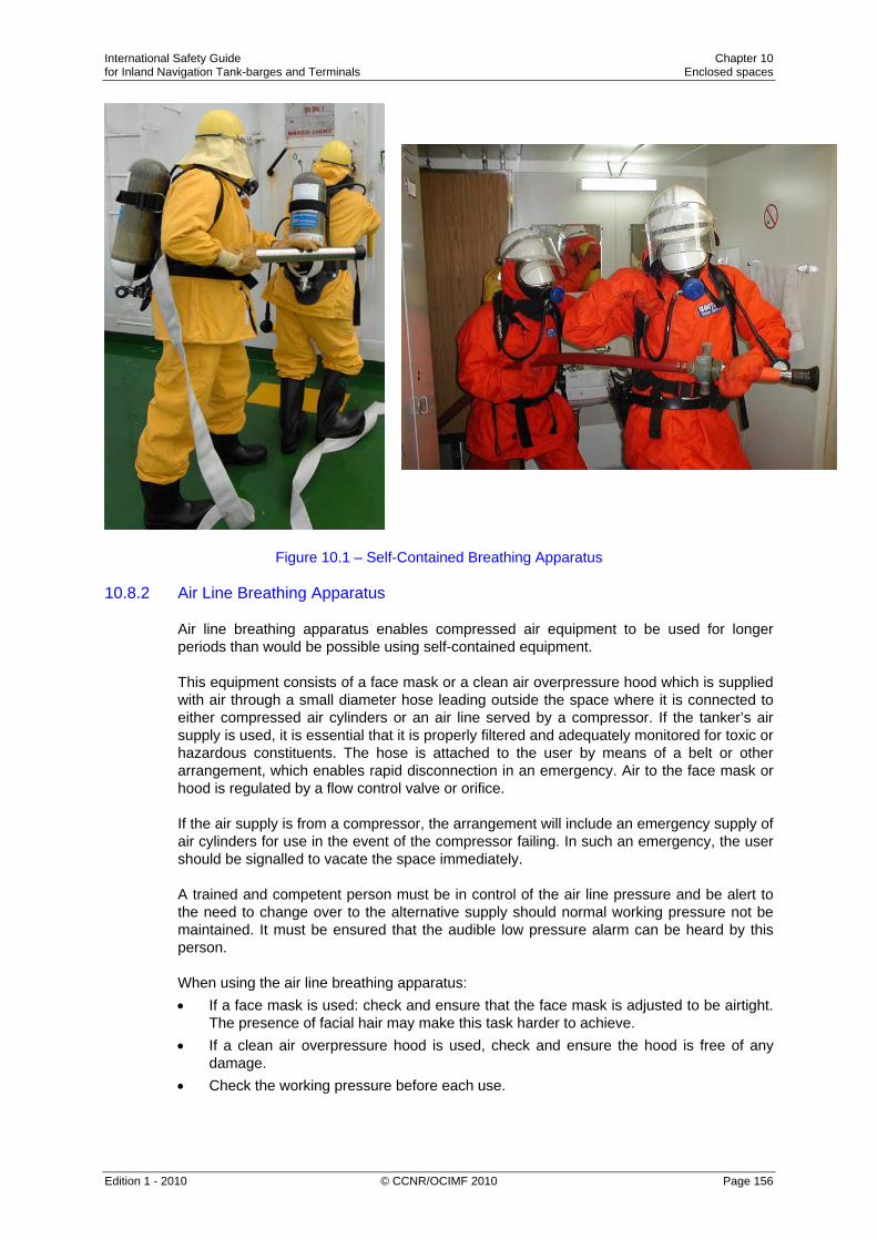
International Safety Guide Chapter 10 for Inland Navigation Tank-barges and Terminals Enclosed spaces
Edition 1 - 2010 © CCNR/OCIMF 2010 Page 156
Figure 10.1 – Self-Contained Breathing Apparatus 10.8.2 Air Line Breathing Apparatus
Air line breathing apparatus enables compressed air equipment to be used for longer periods than would be possible using self-contained equipment. This equipment consists of a face mask or a clean air overpressure hood which is supplied with air through a small diameter hose leading outside the space where it is connected to either compressed air cylinders or an air line served by a compressor. If the tanker’s air supply is used, it is essential that it is properly filtered and adequately monitored for toxic or hazardous constituents. The hose is attached to the user by means of a belt or other arrangement, which enables rapid disconnection in an emergency. Air to the face mask or hood is regulated by a flow control valve or orifice. If the air supply is from a compressor, the arrangement will include an emergency supply of air cylinders for use in the event of the compressor failing. In such an emergency, the user should be signalled to vacate the space immediately. A trained and competent person must be in control of the air line pressure and be alert to the need to change over to the alternative supply should normal working pressure not be maintained. It must be ensured that the audible low pressure alarm can be heard by this person. When using the air line breathing apparatus: • If a face mask is used: check and ensure that the face mask is adjusted to be airtight.
The presence of facial hair may make this task harder to achieve. • If a clean air overpressure hood is used, check and ensure the hood is free of any
damage. • Check the working pressure before each use.

International Safety Guide Chapter 10 for Inland Navigation Tank-barges and Terminals Enclosed spaces
Edition 1 - 2010 © CCNR/OCIMF 2010 Page 157
• Check the audible low pressure alarm before each use. • To avoid damage, keep the air lines clear of sharp projections. • Ensure that the air hose has sufficient length for the intended operations but does not
exceed 25 metres. • Ensure the air hose is of a type that is kink free, antistatic and oil/chemical resistant. • Allow ample time to vacate the space when the low pressure alarm sounds. The
duration of the emergency air for the user will depend on the individual’s weight, fitness and level of exertion, and each user should be aware of their particular limitations.
Should there be any doubt about the efficiency of the equipment, the user should vacate the space immediately. It is recommended the user should carry a completely separate supply of clean air for use in emergency evacuation from the space in the event of the air line failing. It is recommended that the user should carry an Emergency Escape Breathing Device (EEBD).
10.8.3 Emergency Escape Breathing Device (EEBD) This is a compressed air or oxygen breathing device used for escape from a compartment where the atmosphere has become hazardous while a person is within it. Additional sets should be provided for use as emergency escape equipment during enclosed space entry. Each set has a duration of not less than 10 minutes. The device can be one of two types:

International Safety Guide Chapter 10 for Inland Navigation Tank-barges and Terminals Enclosed spaces
Edition 1 - 2010 © CCNR/OCIMF 2010 Page 158
Compressed Air Type These sets consist of an air bottle, reducing valve, air hose, face mask or hood and a flame retardant high visibility bag or jacket. They are normally constant flow devices providing compressed air to the wearer at a rate of approximately 40 litres per minute, giving aduration of 10 (as a minimum) or 15 minutes, depending on the capacity of the bottle. Compressed air EEBDs can normally be recharged on board with a conventional SCBA compressor. The pressure gauge, supply valve and hood should be checked before use. Re-Breathing Type These sets normally consist of a robust watertight carrying case, compressed oxygen cylinder, breathing bag, mouthpiece and a flame retardant hood. They are designed for single use by the wearer. When the hood is placed over the user’s head and the set activated, exhaled air is mixed with compressed oxygen inside the breathing bag to allow the wearer to breath normally when escaping from a hazardous atmosphere. It is stressed that EEBDs are for emergency escape, and should not be used as the primary means for entering oxygen deficient compartments, or while fighting fires.
10.8.4 Cartridge or Canister Face Masks These units consist of a cartridge or canister attached to a face mask. They are designed to purify the air of specific contaminants. They do not supply any further air. It is important that they are only used for their designed purpose and within the limits prescribed by manufacturers. Such limits include an expiry date for the cartridge or canister. Cartridge or canister face masks will not protect the user against concentrations of hydrocarbon or toxic vapours in excess of their design parameters, or against oxygen deficiency, and they should never be used in place of breathing apparatus or in enclosed spaces.
Figure 10.2 – Examples of Cartridges for use in Face Masks
International Safety Guide Chapter 10 for Inland Navigation Tank-barges and Terminals Enclosed spaces
Edition 1 - 2010 © CCNR/OCIMF 2010 Page 159
10.8.5 Hose Mask (Fresh Air Breathing Apparatus)
This equipment consists of a mask supplied with air from a large diameter hose connected to a rotary pump or bellows. It is cumbersome and provides no seal against the entry of gases. Although hose masks may be found on some tankers, they should not be used for enclosed space entry. Although most legislations prescribe carriage of this type of breathing apparatus, it is not recognised as being adequate and safe respiratory equipment.
10.8.6 Equipment Maintenance All respiratory protective equipment should be examined and tested by a Responsible Person at regular intervals. Defects should be made good promptly and a record should be kept of inspections and repairs. Air bottles must be recharged as soon as possible after use. Air bottles must not be in a damaged or corroded condition and should be tested hydraulically, in accordance with legislative requirements. Masks and helmets should be cleaned and disinfected after use. Any repair or maintenance must be carried out strictly in accordance with the manufacturer’s instructions. All respiratory protective equipment should be examined and certified by an authorised company in accordance with the intervals and conditions prescribed in manufacturer’s instructions and/or (inter)national legislation.
10.8.7 Stowage Breathing apparatus should be stowed fully assembled in a place where it is readily accessible. Air bottles should be fully charged and the adjusting straps kept slack. Units should be sited so as to be available for emergencies in different parts of the tanker.
10.8.8 Training Practical demonstrations and training in the use of breathing apparatus should be carried out to give personnel experience in its use. Only trained personnel should use self-contained and air line breathing apparatus, since incorrect or inefficient use can endanger the user’s life.
10.9 Work in Enclosed Spaces 10.9.1 General Requirements
All work carried out in enclosed spaces should be conducted under the control of the Safety Management System. All conditions for entry, including the use of an entry permit, should be observed

International Safety Guide Chapter 10 for Inland Navigation Tank-barges and Terminals Enclosed spaces
Edition 1 - 2010 © CCNR/OCIMF 2010 Page 160
Additional precautions may be necessary to ensure there is no loose scale, sludge or combustible material in the vicinity of the work site which, if disturbed or heated, could give off toxic or flammable gases. Effective ventilation should be maintained and, where practicable, directed towards the work area.
10.9.2 Opening Equipment and Fittings Whenever cargo pumps, pipelines, valves or heating coils are to be opened, they should first be thoroughly flushed with water. However, even after flushing, there will always be a possibility of some cargo remaining, which could be a source of further flammable or toxic gas. Whenever such equipment is to be opened, the safety management procedure should identify the minimum safe working practices to be adopted, including any requirement for additional gas tests.
10.9.3 Use of Tools Tools should not be carried into enclosed spaces, but should be lowered in a plastic bucket or canvas bag to avoid the possibility of their being dropped. Before any hammering or chipping is undertaken, or any power tool is used, the Responsible Person should be satisfied that there is no likelihood of hazardous vapour being present in the vicinity.
10.9.4 Use of Electric Lights and Electrical Equipment Unless a compartment is designated safe for Hot Work by an approved safe system of work, such as a Hot Work permit, non-approved lights or non-intrinsically safe electrical equipment must not be taken into an enclosed space. Only approved safety lighting or intrinsically safe electrical equipment should be used in enclosed spaces that are liable to experience hazardous vapour re-contamination. In port, any local regulations concerning the use of electric lights or electrical equipment should be observed.
10.9.5 Removal of Sludge, Scale and Sediment When removing sludge, scale or sediment from an enclosed space, periodic gas tests should be undertaken and continuous ventilation should be maintained throughout the period the space is occupied. There may be increases in gas concentrations in the immediate vicinity of the work and care should be taken to ensure that the atmosphere remains safe for personnel. It is strongly recommended that personal gas monitors are provided to some or all of the persons engaged in the work.
10.9.6 N/A

International Safety Guide Chapter 10 for Inland Navigation Tank-barges and Terminals Enclosed spaces
Edition 1 - 2010 © CCNR/OCIMF 2010 Page 161
10.10 Pumproom Entry Precautions
Cargo pumprooms are to be considered as enclosed spaces and the requirements of this Chapter should be followed to the maximum extent possible. However, because of their location, design and the operational need for the space to be routinely entered by personnel, pumprooms present a particular hazard and therefore necessitate special precautions, which are described in the following Sections.
10.10.1 Ventilation Because of the potential for the presence of flammable gas in the pumproom, the use of mechanical ventilation by extraction to maintain the atmosphere in a safe condition is required. The cargo pump-room should be provided with a permanent gas-detection system which automatically indicates the presence of explosive gases or lack of oxygen by means of direct-measuring sensors and which actuates a visual and audible alarm when the gas concentration has reached 10% of the lower explosive limit. The sensors of this system should be placed at suitable positions at the bottom and directly below the deck. Measurement should be continuous. Audible and visual alarms should be installed in the wheelhouse and in the cargo pump-room and, when the alarm is actuated, the loading and unloading system should shut down. Failure of the gas detection system should be immediately signalled in the wheelhouse and on deck by means of audible and visual alarms. The ventilation system should have a capacity of not less than 30 changes of air per hour based on the total volume of the service space. Ventilation should be continuous until access is no longer required, or cargo operations have been completed.
10.10.2 Pumproom Entry Procedures Before anyone enters a pumproom, it should be thoroughly ventilated, the oxygen content of the atmosphere verified and the atmosphere checked for the presence of hydrocarbons and any toxic gas associated with the cargo being handled. Only where a fixed gas detection system • is correctly calibrated and tested and • provides gas readings as a percentage LEL (% LEL) to a level of accuracy equivalent
to portable gas instruments, at representative locations within the pumproom, should this gas detecting system be used to provide information for safe entry into the space. Formal procedures should be in place to control pumproom entry. The procedure used should be based on a risk assessment, and should ensure that risk mitigation measures are followed and that entries into the space are recorded.

International Safety Guide Chapter 10 for Inland Navigation Tank-barges and Terminals Enclosed spaces
Edition 1 - 2010 © CCNR/OCIMF 2010 Page 162
A communications system should provide links between the pumproom, navigation bridge, engine room and cargo control room. In addition, audible and visual repeaters for essential alarm systems, such as the general alarm and the fixed extinguishing system alarm, should be provided within the pumproom. Arrangements should be established to enable effective communication to be maintained at all times between personnel within the pumproom and those outside. Regular communication checks should be made at pre-agreed intervals and failure to respond should be cause to raise the alarm. VHF/UHF communication should not be used as a primary communication method where it is known that reception may not be reliable or practicable due to noise. Where communication by VHF/UHF is difficult, it is recommended that a standby person is positioned on the pumproom top and that a visual and remote communication procedure is put in place. The frequency of pumproom entry for routine inspection purposes during cargo operations should be reviewed with a view to minimising personnel exposure. Notices should be displayed at the pumproom entrance prohibiting entry without formal permission. The following instruction should be displayed at the entrance of the cargo pump-room:
Before entering the cargo pump-room, check whether it is free from gases and contains sufficient oxygen.
Do not open doors and entrance openings without the permission of the Master.
Leave immediately in the event of an alarm.
10.11 Pumproom Operational Precautions
A pumproom contains the largest concentration of cargo pipelines of any space within the tanker and leakage of a volatile product from any part of this system could lead to the rapid generation of a flammable or toxic atmosphere. The pumproom may also contain a number of potential ignition sources unless formal, structured maintenance, inspection and monitoring procedures are strictly followed.
10.11.1 General Precautions Before starting any cargo operation: • An inspection should be made to ensure that strainer covers, inspection plates and
drain plugs are in position and secure. • Drain valves in the pumproom cargo system, especially those on cargo oil pumps,
should be firmly closed. • Any bulkhead glands should be checked and adjusted or lubricated, as necessary, to
ensure an efficient gas-tight seal between the pumproom and the machinery space.

International Safety Guide Chapter 10 for Inland Navigation Tank-barges and Terminals Enclosed spaces
Edition 1 - 2010 © CCNR/OCIMF 2010 Page 163
During all cargo operations, including loading: • The pumproom should be inspected at regular intervals to check for leakages from
glands, drain plugs and drain valves, especially those fitted to the cargo pumps. • If the pumps are in use, pump glands, bearings and the bulkhead glands (if fitted)
should be checked for overheating. In the event of leakage or overheating, the pump should be stopped.
• No attempt should be made to adjust the pump glands on rotating shafts while the pump is in service.
10.11.2 Cargo and Ballast Line Draining Procedures
On some tankers, no provision is made for effective line draining and, in order to meet the demands of certain product trades, final line contents are drained to the pumproom bilge. This is an unsafe practice and it is recommended that cargo procedures be reviewed with the aim of preventing a volatile product being drained to the bilge. It is strongly recommended that consideration is given to the provision of a comprehensive stripping arrangement to enable all lines and pumps to be drained effectively to a cargo tank, slop tank or dedicated reception tank, for subsequent discharge ashore. Where lines that have been used for ballast have to be drained to the pumproom bilge on completion of deballasting, care must be taken to ensure that such drainings do not contain cargo remains.
10.11.3 Routine Maintenance and Housekeeping Issues It is important that the integrity of pipelines and pumps is maintained and that any leaks are detected and rectified in a timely fashion. Pumproom bilges should be kept clean and dry. Particular care should be taken to prevent the escape of flammable liquids or vapour into the pumproom. Pipelines should be visually examined and subjected to routine pressure tests to verify their condition. Other means of non-destructive testing or examination, such as ultrasonic wall thickness measurement, may be considered appropriate, but should always be supplemented by visual examination. Procedures should be established to verify that mud boxes and filters are properly sealed after they have been opened up for routine cleaning or examination. Valve glands and drain cocks should be regularly inspected to ensure that they do not leak. Bulkhead penetrations should be routinely checked to ensure the effectiveness of seals. Critical bolts on the cargo pumps and associated fittings, such as pedestal fixing bolts, pump casing bolts and bolts securing shaft guards, should be secure. In addition, requirements for their examination should be included in routine maintenance procedures. The pumproom rescue harness and rope should be checked regularly to ensure it is fit for use and rigged for immediate operation.

International Safety Guide Chapter 10 for Inland Navigation Tank-barges and Terminals Enclosed spaces
Edition 1 - 2010 © CCNR/OCIMF 2010 Page 164
Emergency escape routes should be checked regularly to ensure that they are properly marked and clear of obstructions. Where an escape trunk is fitted, doors should be checked for ease of operation, door seals should be effective and lighting within the trunk should be operational.
10.11.4 Maintenance of Electrical Equipment in the Pumproom The integrity of the protection afforded by the design of explosion-proof or intrinsically safe electrical equipment may be compromised by incorrect maintenance procedures. Even the simplest of repair and maintenance operations must be carried out in strict compliance with the manufacturer’s instructions in order to ensure that such equipment remains in a safe condition. Maintenance of explosion-proof and intrinsically safe equipment should only be carried out by personnel qualified to undertake such work. This is particularly relevant in the case of explosion-proof lights, where incorrect closure after changing a lamp could compromise the integrity of the light. In order to assist with such routine servicing and repair, tankers should be provided with detailed maintenance instructions for the specific systems and arrangements as fitted on board.
10.11.5 Inspection and Maintenance of Pumproom Ventilation Fans Pumproom ventilation fans are required to operate by drawing air out of the space. As a consequence, should gas be present in the pumproom, the vapours will be drawn through the blades of the fan impeller and could be ignited if the blades contact the casing or if the fan bearings or seals overheat. Pumproom extractor fans, including impellers, shafts and gas seals, should be inspected on a regular basis. The condition of the fan trunking should be inspected and the proper operation of changeover flaps and fire dampers confirmed. Routine vibration monitoring and analysis should be considered as a means for providing early detection of component wear.
10.11.6 Testing of Alarms and Trips Pump alarms and trips, level alarms, etc, where fitted, should be tested regularly to ensure that they are functioning correctly, and the results of these tests should be recorded. These tests should be as thorough as possible to verify the full and complete operability of the system and should not be limited to an electrical function test of the alarm itself.
10.11.7 Miscellaneous There are a number of other ways to enhance the safety of pumprooms, some of which are mandatory for certain tankers: • A fixed gas detection system capable of continuously monitoring for the presence of
flammable gas. Where such equipment is fitted, procedures should be developed to ensure it is regularly inspected and calibrated. Procedures should also be developed with regard to the action to be taken in the event of an alarm occurring, especially for vacating the space and stopping the cargo pumps. Whenever practicable, gas detection should monitor a number of levels within the pumproom, not just the lower area.

International Safety Guide Chapter 10 for Inland Navigation Tank-barges and Terminals Enclosed spaces
Edition 1 - 2010 © CCNR/OCIMF 2010 Page 165
• A fixed sampling arrangement to enable the oxygen content within the pumproom to
be monitored from the deck by a portable meter prior to pumproom entry. Where such an arrangement is fitted, it should ensure that remote parts of the pumproom can be monitored.
• Temperature monitoring devices fitted to the main cargo pumps in order to provide remote indication of the temperature of pump casings, bearings and bulkhead seals. Where such equipment is fitted, procedures should be developed with regard to the action to be taken in the event of an alarm occurring.
• A high level alarm in pumproom bilges which activates audible and visual alarms in the cargo control room, engine room and the navigating bridge.
• Manually activated trips for the main cargo pumps provided at the lower pumproom level and at the top (main deck) level.
• Spray arrestors around the glands of all rotary cargo pumps in order to reduce the formation of mists in the event of minor leakage from the gland.
• Examining the feasibility of fitting a double seal arrangement to contain any leakage from the primary seal and to activate a remote alarm to indicate that leakage has occurred. However, the impact of any retrofit on the integrity of the pump will need to be clearly assessed in conjunction with the pump manufacturer.
• Particular attention to be given to the adequacy of fire protection in the immediate vicinity of the cargo pumps.
• Because of the problems associated with flashback re-ignition after the use of the primary fire-fighting medium, consideration should be given to the need to provide a backup system, such as high expansion foam or water drenching, to supplement the existing system.
• On tankers fitted with an inert gas system, the provision of an emergency facility for inerting the pumproom could be an option, although careful attention must be paid to the safety and integrity of the arrangement.
• The provision of Emergency Escape Breathing Devices (EEBDs) located within the pumproom and readily accessible.

International Safety Guide Chapter 10 for Inland Navigation Tank-barges and Terminals Enclosed spaces
Edition 1 - 2010 © CCNR/OCIMF 2010 Page 166

International Safety Guide Chapter 11 for Inland Navigation Tank-barges and Terminals Shipboard operations
Edition 1 - 2010 © CCNR/OCIMF 2010 Page 167
Chapter 11
SHIPBOARD OPERATIONS This Chapter provides information on the full range of shipboard operations, including loading and discharging of cargo, hose clearing, tank cleaning and gas freeing, ballasting, tanker-to-tanker transfers and mooring. The Chapter also includes information on the safe handling of particular cargoes, such as static accumulator oils, those having a high vapour pressure and those containing hydrogen sulphide. Other operations that are addressed include the use of vapour emission control systems and efficient stripping. 11.1 Cargo Operations 11.1.1 General
All cargo operations should be carefully planned and documented well in advance of their execution. The details of the plans should be discussed with all personnel, both on the tanker and at the terminal. Plans may need to be modified following consultation with the terminal and following changing circumstances, either on board or ashore. Any changes should be formally recorded and brought to the attention of all personnel involved with the operation. Chapter 22 contains details of cargo plans and communications regarding them.
11.1.2 Setting of Lines and Valves Before commencement of any loading or discharging operation, the tanker’s cargo pipelines and valves should be set as per the required loading or discharging plan by a Responsible Person and checked, independently, by other personnel.
11.1.3 Valve Operation
To avoid pressure surges, valves at the downstream end of a pipeline system should not be closed against the flow of liquid, except in an emergency. This should be stressed to all personnel responsible for cargo handling operations, both on the tanker and at the terminal. (See Section 11.1.4 below.) In general, where pumps are used for cargo transfer, all valves in the transfer system (both tanker and shore) should be open before pumping begins, although the discharge valve of a centrifugal pump may be kept closed until the pump is up to speed and the valve then opened slowly. In the case of tankers loading by gravity, the final valve to be opened should be that at the shore tank end of the system.

International Safety Guide Chapter 11 for Inland Navigation Tank-barges and Terminals Shipboard operations
Edition 1 - 2010 © CCNR/OCIMF 2010 Page 168
If the flow is to be diverted from one tank to another, either the valve on the second tank should be opened before the valve on the first tank is closed, or pumping should be stopped while the change is being made. Valves that control liquid flow should be closed slowly. The time taken for power operated valves to move from open to closed, and from closed to open, should be checked regularly at their normal operating temperatures.
11.1.4 Pressure Surges The incorrect operation of pumps and valves can produce pressure surges in a pipeline system. These surges may be sufficiently severe to damage the pipeline, hoses or metal arms. One of the most vulnerable parts of the system is the tanker-to-shore connection. Pressure surges are produced upstream of a closing valve and may become excessive if the valve is closed too quickly. They are more likely to be severe where long pipelines and high flow rates are involved. Where the risk of pressure surges exists, information should be exchanged and written agreement reached between the tanker and the terminal concerning the control of flow rates, the rate of valve closure, and pump speeds. This should include the closure period of remotely controlled and automatic shutdown valves. The agreement should be included in the operational plan. (Generation of pressure surges in pipelines is discussed in more detail in Section 16.8.)
11.1.5 Butterfly and Non-Return (Check) Valves Butterfly and pinned back non-return valves in tanker and shore cargo systems have been known to slam shut when cargo is flowing through them at high rates, thereby setting up very large surge pressures which can cause line, hose or metal arm failures and even structural damage to jetties. These failures are usually due to the valve disc not being completely parallel to, or fully withdrawn from, the flow when in the open position. This can create a closing force that may shear either the valve spindle, in the case of butterfly valves, or the hold open pin, in the case of pinned back non-return valves. It is therefore important to check that all such valves are fully open when they are passing cargo or ballast.
11.1.6 Loading Procedures 11.1.6.1 General
The responsibility for safe cargo handling operations is shared between the tanker and the terminal and rests jointly with the tanker’s captain and the Terminal Representative. The manner in which the responsibility is shared should therefore be agreed between them so as to ensure that all aspects of the operations are covered.
11.1.6.2 Joint Agreement on Readiness to Load Before starting to load cargo, the Responsible Person and the Terminal Representative should formally agree that both the tanker and the terminal are ready to do so safely.

International Safety Guide Chapter 11 for Inland Navigation Tank-barges and Terminals Shipboard operations
Edition 1 - 2010 © CCNR/OCIMF 2010 Page 169
11.1.6.3 Emergency Shutdown System
An emergency shutdown procedure, and alarm, should be agreed between the tanker and the terminal and recorded on an appropriate form. The agreement should designate those circumstances in which operations must be stopped immediately. Due regard should be given to the possible dangers of a pressure surge associated with any emergency shutdown procedure (see Section 16.8). Tankers can be equipped with following emergency shut down systems: During loading: If provided with a shut down system, cargo tank high level sensors are installed in each cargo tank. When activated, they should give a visual and audible alarm on board and at the same time actuate an electrical contact which in the form of a binary signal interrupts the electric current loop provided and fed by the shore facility, thus initiating measures at the shore facility against overflowing during loading operations. The signal should be transmitted to the shore facility via a watertight two-pin plug of a connector device in accordance with (e.g.) standard EN 60309-2 : 1999 for direct current of 40 to 50 volts, identification colour white, position of the nose 10 h. The plug should be permanently fitted to the tanker close to the manifold position. The high level sensor should also have the capability of shutting down the tanker’s pumps when discharging. It is recommended that the high level sensor is independent of the level alarm device. During discharging: During discharging by means of the on-board pump, a shut down system will make it possible for the shore facility to shut down the tanker’s pumps. For this purpose, an independent intrinsically safe circuit, fed by the vessel, is switched off by the shore facility by means of an electrical contact. It should be possible for the binary signal of the shore facility to be transmitted via a watertight two-pole socket or a connector device in accordance with (e.g.) standard EN 60309-2 : 1999, for direct current of 40 to 50 volts, identification colour white, position of the nose 10 h. This socket should be permanently fitted to the vessel close to the shore connections of the transfer system.

International Safety Guide Chapter 11 for Inland Navigation Tank-barges and Terminals Shipboard operations
Edition 1 - 2010 © CCNR/OCIMF 2010 Page 170
11.1.6.4 Supervision
The following safeguards should be maintained throughout loading: - A Responsible Person should be on watch and sufficient crew should be on board to
deal with the operation and security of the tanker. A continuous watch of the tank deck should be maintained.
- The agreed tanker-to-shore communications system should be maintained in good working order.
- At the commencement of loading, and at each change of watch or shift, the Responsible Person and the Terminal Representative should each confirm that the communications system for the control of operations is understood by them and by personnel on watch and on duty.
- The standby requirements for the normal stopping of pumps on completion of cargo transfer, and the emergency stop system for both the tanker and terminal, should be fully understood by all personnel concerned.
11.1.6.5 Inert Gas Procedures
Prior to the commencement of loading, the inert gas plant, if installed and applicable, should be closed down and the inert gas pressure in the tanks to be loaded reduced.
11.1.6.6 Loading A: closed loading For effective closed loading, cargo should be loaded with the ullage, sounding and sighting ports securely closed. The gas displaced by the incoming cargo should be vented to the atmosphere through high velocity valves to ensure that the gases are taken clear of the cargo deck. Devices fitted to vent stacks to prevent the passage of flames should be regularly checked to confirm they are clean, in good condition and correctly installed. For some products, local, national or international legislation may prohibit the venting of cargo vapours to the atmosphere. If this is the case, closed loading has to employed in conjunction with vapour balancing with the loading terminal. In this case, the Terminal must ensure that the maximum vapour pressure inside the cargo tank of the tanker will not reach the setting of the high pressure velocity valve at any stage of the operation. In order to undertake closed loading, the vessel should be equipped with ullaging equipment that allows the tank contents to be monitored without opening tank apertures. (Closed gauging and sampling is discussed in detail in Section 11.8.1.) There is a risk of overfilling a cargo tank when loading under normal closed conditions. Due to the reliance placed on closed gauging systems, it is important that they are fully operational and that backup is provided in the form of an independent overfill alarm arrangement. The alarm should provide audible and visual indication and should be set at a level that will enable operations to be shut down prior to the tank being overfilled. Under normal operations, the cargo tank should not be filled higher than the level at which the overfill alarm is set.

International Safety Guide Chapter 11 for Inland Navigation Tank-barges and Terminals Shipboard operations
Edition 1 - 2010 © CCNR/OCIMF 2010 Page 171
Individual overfill alarms should be tested at the tank to ensure their proper operation prior to commencing loading, unless the system is provided with an electronic self-testing capability which monitors the condition of the alarm circuitry and sensor and confirms the instrument set point. If, after testing the overfill alarms, it appears the overfill alarm is not working properly loading should not be commenced. On vessels without inert gas systems, this equipment should comply with the precautions highlighted in Section 11.8.2. Vessels operating with inert gas are considered always to be capable of closed loading. B: Open loading For some products, local, national or international legislation may allow displaced gas to be vented through cargo tank sighting ports, provided they are protected with a flame screen, which is a good fit and is clean and in good condition. In all cases it must be ensured that the gases are taken clear of the cargo deck. It is not recommended that open loading is routinely employed when handling volatile products generating flammable vapours. If it is expected that flammable cargo vapours are accumulating on the cargo deck, loading must be stopped immediately.
11.1.6.7 Commencement of Loading Alongside a Terminal When all necessary terminal and tanker valves in the loading system are open, and the tanker has signified its readiness, loading can commence. The initial flow should be at a slow rate. Whenever possible, this should be by gravity and to a single tank, with the shore pumps not being started until the system has been checked and the tanker advises that cargo is being received in the correct tank(s). When the pumps have been started, the tanker/shore connections should be checked for tightness until the agreed flow rate or pressure has been reached.
11.1.6.8 N/A 11.1.6.9 N/A 11.1.6.10 N/A 11.1.6.11 Loading Through Pumproom Lines
Due to the increased risk of leakage in the pumproom, it is not good practice to load cargo via pumproom lines. Whenever possible, cargo should be loaded through drop lines within the cargo tank area, with all pumproom valves closed.
11.1.6.12 Cargo Sampling on Commencement of Loading Where facilities exist, a sample of the cargo should be taken as soon after the commencement of loading as possible. This will allow the product’s visual quality to be checked to ensure the correct grade is being loaded. This should be done before opening up subsequent tanks for loading. (See Appendix 7.)

International Safety Guide Chapter 11 for Inland Navigation Tank-barges and Terminals Shipboard operations
Edition 1 - 2010 © CCNR/OCIMF 2010 Page 172
On non-inerted tankers loading static accumulator cargoes, precautions against static electricity hazards should be observed when taking the sample. (See Section 11.1.7.)
11.1.6.13 Periodic Checks During Loading Throughout loading, the tanker should monitor and regularly check all full and empty tanks to confirm that cargo is only entering the designated cargo tanks and that there is no escape of cargo into pumprooms or cofferdams. The tanker should check tank ullages/innages at least hourly and calculate a loading rate. Cargo figures and rates should be compared with shore figures to identify any discrepancy. On tankers where stress considerations may be critical, hourly checks should include, where possible, the observation and recording of the shear forces, bending moments, draught and trim and any other relevant stability requirements particular to the tanker. This information should be checked against the required loading plan to confirm that all safe limits are adhered to and that the loading sequence can be followed, or amended, as necessary. Any discrepancies should be reported immediately to the Responsible Person. Any unexplained drop in pressures, or any marked discrepancy between tanker and terminal estimates of quantities transferred, could indicate pipeline or hose leaks, and require that cargo operations be stopped until investigations have been made. The tanker should carry out frequent inspections of the cargo deck and pumproom to check for any leaks. Overside areas should likewise be checked regularly. During darkness, where safe and practical, the water around the vessel should be illuminated.
11.1.6.14 Fluctuation of Loading Rate The loading rate should not be substantially changed without informing the tanker.
11.1.6.15 Cessation of Pumping by the Terminal Many terminals require a standby period for stopping pumps and this should be understood and noted as discussed under item 24 of the guidelines for completing the Tanker/Shore Safety Check-List before loading commences (see Section 26.4).
11.1.6.16 Topping-Off on board the Tanker The tanker should advise the terminal when tanks are to be topped-off and request the terminal, in adequate time, to reduce the loading rate sufficiently to permit effective control of the flow on board the tanker. After topping-off individual tanks, master valves should be closed, where possible, to provide two-valve segregation of loaded tanks. The ullages/innages of topped-off tanks should be checked from time to time to ensure that overflows do not occur as a result of leaking valves or incorrect operations. In general, the tanker should give the terminal notice when the last cargo tank will be loaded.

International Safety Guide Chapter 11 for Inland Navigation Tank-barges and Terminals Shipboard operations
Edition 1 - 2010 © CCNR/OCIMF 2010 Page 173
The number of valves to be closed during the topping-off period should be reduced to a minimum. The tanker should not close all its valves against the flow of oil. Where possible, the completion of loading should be done by gravity. If pumps have to be used to the end, their delivery rate during the ‘standby’ time should be regulated so that shore control valves can be closed as soon as requested by the tanker. Shore control valves should be closed before the tanker’s valves.
11.1.6.17 Checks After Loading After the completion of loading, a Responsible Person should check that all valves in the cargo system are closed, that all appropriate tank openings are closed and that pressure/vacuum relief valves are correctly set.
11.1.7 Loading Static Accumulator Oils 11.1.7.1 General
Petroleum distillates often have electrical conductivities of less than 50 picoSiemens/metre (pS/m) and thus fall into the category of static accumulators. Since the conductivities of distillates are not normally known, they should all be treated as static accumulators unless they contain an antistatic additive, which raises the conductivity of the product above 50 pS/m. (See Section 11.1.7.9 regarding cautions on the effectiveness of antistatic additives.) A static accumulator may carry sufficient charge to constitute an incendive ignition hazard during loading into the tank, and for up to 30 minutes after completion of loading. Bonding (see Section 3.2.2) is an essential precaution for preventing electrostatic charge accumulation and its importance cannot be over-emphasised. However, while bonding assists relaxation, it does not prevent accumulation and the production of hazardous voltages. Bonding therefore should not be seen as a universal remedy for eliminating electrostatic hazards. This Section describes methods for controlling electrostatic generation, by preventing charge separation, which is another essential precaution (see Section 3.1.2).
11.1.7.2 Controlling Electrostatic Generation Electrostatic discharge has long been known as a hazard associated with the handling of flammable products. FAILURE TO FOLLOW THE GUIDANCE GIVEN IN THIS SECTION WILL LEAD TO THE HAZARDOUS CONDITIONS REQUIRED FOR ELECTROSTATIC IGNITION ACCIDENTS TO OCCUR. When a tank is known to be in an inert condition, no antistatic precautions are necessary.

International Safety Guide Chapter 11 for Inland Navigation Tank-barges and Terminals Shipboard operations
Edition 1 - 2010 © CCNR/OCIMF 2010 Page 174
If a flammable atmosphere is possible within the tank, then specific precautions will be required with regard to maximum flow rates and safe ullaging/innaging, sampling and gauging procedures when handling static accumulator products. Mixtures of oil and water constitute a potent source of static electricity. Extra care should therefore be taken to prevent excess water and unnecessary mixing.
11.1.7.3 During Initial Filling of a Tank The generally accepted method for controlling electrostatic generation in the initial stages of loading is to restrict the velocity of oil entering the tank to 1 metre/second until the tank inlet is well covered and all splashing and surface turbulence in the tank has ceased. The 1 metre/second limit applies in the branch line to each individual cargo tank and should be determined at the smallest cross-sectional area including valves or other piping restrictions in the last section before the tank’s loading inlet.
Diameter Approx. flow rate (m3/h)
3'' / 80 mm 17
4'' / 100 mm 29
6'' / 150 mm 67
8'' / 200 mm 116
10'' / 250 mm 183
12'' / 300 mm 262
Table 11.1 - Rates corresponding to 1 metre/second * Note that the diameters given are nominal diameters,
which are not necessarily the same as the actual internal diameters. Table 11.1 shows approximate volumetric flow rates that correspond to a linear velocity of 1 metre/second in piping of various diameters. The reasons for such a low linear velocity as 1 metre/second are threefold: 1. At the beginning of filling a tank, there is the greatest likelihood of water being mixed
with the oil entering the tank. Mixtures of oil and water constitute a most potent source of static electricity.
2. A low product velocity at the tank inlet minimises turbulence and splashing as oil enters the tank. This helps reduce the generation of static electricity and also reduces the dispersal of any water present, so that it quickly settles out to the bottom of the tank where it can lie relatively undisturbed when the loading rate is subsequently increased.

International Safety Guide Chapter 11 for Inland Navigation Tank-barges and Terminals Shipboard operations
Edition 1 - 2010 © CCNR/OCIMF 2010 Page 175
3. A low product velocity at the tank inlet minimises the formation of mists that may
accumulate a charge, even if the oil is not considered to be a static accumulator. This is because the mist droplets are separated by air, which is an insulator. A mist can result in a flammable atmosphere even if the liquid has a high flashpoint and is not normally capable of producing a flammable atmosphere.
Figure 11.1 provides a flow chart to assist in deciding the precautions that need to be taken when loading static accumulator cargoes.
11.1.7.4 Minimising Hazards From Water Because mixtures of oil and water constitute a potent source of static electricity, care should be taken to prevent excess water from operations such as water washing, ballasting or line flushing entering a tank that contains or will contain a static accumulator oil. For example, cargo tanks and lines that have been flushed with water should be drained before loading and water should not be permitted to accumulate in tanks. Lines should not be displaced with water back into a tank containing a static accumulator cargo. Any water remaining within the shore or tanker pipeline system after the initial filling period might be flushed into the cargo tank when loading at the maximum rate. (The minimum product velocity for flushing water out of pipelines effectively is 1 metre per second.) The resulting mixing and agitating of the oil and water in the tank will increase the generation of static charge to a level that is unsafe in a flammable atmosphere. Before increasing to the bulk loading rate, it is therefore necessary to ensure that, so far as practicable, all excess water that may have been lying in low spots in the pipelines has been flushed out of the system either before loading commenced or during the initial filling of the tank (see Section 11.1.7.3 for advice on the process). Under normal circumstances, and provided that the aforementioned precautions to prevent excess water have been taken, the amount of water still present in the system after the initial filling period will be insufficient to increase static separation when the loading rate is increased. However, if there is reason to believe that excess water may still be present in the shore pipeline, then the recommended action is to: - Keep the product velocity in the shore line below 1 metre per second throughout
loading to avoid flushing the water into the tanker’s tank(s); or - Keep the product velocity at the tank inlet(s) below 1 metre per second throughout
loading to avoid turbulence in the tank(s). Whichever option gives the higher loading rate consistent with safety should be used.

International Safety Guide Chapter 11 for Inland Navigation Tank-barges and Terminals Shipboard operations
Edition 1 - 2010 © CCNR/OCIMF 2010 Page 176
Figure 11.1 - The control hazards associated with the initial loading of static accumulator cargoes
Is the product a Static Accumulator?
(Conductivity of less than 50 picoSiemens/
metre
Are vessel’s tanks inerted?Yes
Controls on initial flow rates for static
accumulators do not apply (other
restrictions may apply – see ISGINTT
7.3.3.2)
Yes
Is product dosed with anti-static additive?
Controls on initial flow rates for static
accumulators do not apply (other
restrictions may apply – see ISGINTT
7.3.3.2)
No
Is spread loaded being considered?
Calculate maximum initial rate to limit flow
to 1m/sec at tank inlet(s)
No
Can minimum initial flow rate be achieved?
Is flow controller installed in the shore
system?Yes
Manually limit flow rate to a maximum of 1m/
sec
No
Operation should not be conducted under prevailing conditions
Flow controller to limit flow rate to a
maximum of 1m/secYes
When tank bottom is covered and all
surface turbulance has ceased, flow rate may
be increased to a maximum of 7m/sec
Note the presence of anti-static additive
should not be relied on to relax controls
Assess risks and agree required
controls
Yes
No
Yes
No
No

International Safety Guide Chapter 11 for Inland Navigation Tank-barges and Terminals Shipboard operations
Edition 1 - 2010 © CCNR/OCIMF 2010 Page 177
11.1.7.5 Examples
Initial Loading Phase Figure 11.2 shows the pipeline arrangements for a vessel loading a static accumulator product at a berth. The table defines the pipeline sizes and the volumetric flow rates at a velocity of 1 metre/second. For initial loading to two cargo tanks, the limitation will allow a loading rate of 366 m3/hour to be requested in the example given. (See also Table 3.2.) If the shore line were 510 mm diameter and water was suspected of being in the line, the vessel would need to load 4 tanks simultaneously to ensure the water content could be safely removed and an initial loading rate of 676 m3/hour should be requested. This will allow the water to be cleared from the shore line whilst keeping the velocity at the tank inlets below 1 metre/second.
11.1.7.6 Practical Considerations In practice, not all terminals are equipped with flow control devices to regulate the loading rate and therefore may not be able to establish a loading rate to one cargo tank equivalent to a velocity of 1 metre/second. Some terminals achieve, or try to achieve, a low loading rate by commencing loading by gravity flow alone.
11.1.7.7 Spread Loading Spread loading is the practice of commencing loading via a single shore line to several of the tanker’s cargo tanks simultaneously where it is necessary to mitigate a terminal’s lack of flow control. The aim of this practice is to achieve a loading rate that will give a maximum velocity at each of the tank inlets of 1 metre per second. Spread loading presents a number of potentially significant static generation risks that should be assessed and properly managed if this practice is to be used safely. For example: - Uneven flow in the tanker’s cargo lines can create a backflow of vapour (gas or air)
from other open tanks to the tank that is receiving product. This eductor effect will create a two-phase mixture of product and vapour that will result in increased turbulence and mist formation within the tank.
- The possibility of exceeding 1 metre/second product velocity at one tank inlet due to uneven distribution of product between the open tanks.
The following precautions should be taken to manage the risks associated with the spread loading of static accumulator cargoes: - The overall loading rate should be selected so as to ensure a maximum product
velocity of 1 metre/second into any one tank, assuming even distribution of cargo between tanks.
- Possible different flow distributions into different tanks should be considered and best efforts should be made to ensure equal flow distribution between cargo tanks.
- Not more than four cargo tanks should be loaded at any one time.

International Safety Guide Chapter 11 for Inland Navigation Tank-barges and Terminals Shipboard operations
Edition 1 - 2010 © CCNR/OCIMF 2010 Page 178
- Tank inlet valves should not be used to control cargo flow in the initial loading phase.
Their use will reduce the cross-sectional area of the inlet, resulting in increased tank inlet velocity and greater turbulence and mist formation. If it is necessary to throttle valves in order to control flow rate, this should be done upstream of the tank valves.
- The management of the risks inherent in spread loading will require a risk assessment process to be followed. The risk assessment should consider: - The terminal’s piping configuration, including flow control capability. - The tanker’s piping configuration. - Tanker’s cargo tank condition, for example previous cargo, tank atmosphere and
physical condition (such as the integrity of heating coils). - The product to be loaded and the potential for generating a flammable
atmosphere. Spread loading should only be carried out when the tanker and the terminal are both satisfied that the risks have been identified and that appropriate risk response measures have been taken to minimise, avoid or eliminate them.
11.1.7.8 Limitation of Product Velocity (Loading Rates) After the Initial Filling Period (Bulk Loading) After the initial filling period, electrostatic generating processes such as mist formation and stirring up tank bottoms by turbulence are suppressed by the rising liquid level, and the concern changes to ensuring that excessive charge does not accumulate on the bulk liquid. This is also done by controlling the flow rate, but the maximum acceptable velocity is higher than for the initial filling period, provided the product is ‘clean’ as defined in Section 3.2.1. Two-phase flows (i.e. through oil and water) give higher charging and may require that flow rate limitations have to be imposed throughout loading (see Section 11.1.7.4). When the tank bottom is covered, after all splashing and surface turbulence has ceased and after all water has been cleared from the line, the rate can be increased to the lesser of the tanker or shore pipeline and pumping system maximum flow rates consistent with proper control of the system. Established practice and experience indicate that hazardous potentials do not occur if the product velocity is less than 7 metres/second. Some national Codes of Practice also suggest 7 metres/second as a maximum value. However, a number of industry documents acknowledge that 7 metres/second is a precautionary limit and imply that higher speeds may be safe, without specifying what the real limits are. (All the empirical relationships for safe loading have been derived on the basis of experiments limited to a maximum flow of 7metres/second.) Only where well documented experience indicates that higher velocities can be safely used should be limit of 7 metres/second be replaced by an appropriate higher value.

International Safety Guide Chapter 11 for Inland Navigation Tank-barges and Terminals Shipboard operations
Edition 1 - 2010 © CCNR/OCIMF 2010 Page 179
Determining the Initial Loading Rate
Line Diameter Flow Rate (m3/h) at 1 m/s Flow Main Shore Pipeline 360 320 Shore Branch Line 305 362
Hose 250 183 Ship’s Cargo and Drop Line 305 262
Tank Inlets 250 183 x 2 = 366 Therefore, an initial loading rate of not more than 366 m3/h should be requested for loading to two tanks simultaneously. This will result in the shore line flowing at more than 1 metre/second which would clear any water lying in the line whilst the velocity at the tank inlets is 1 metre/second. Determining the Maximum Bulk Loading Rate The smallest pipeline in the loading system is the cargo hose with a diameter of 250 mm. A maximum linear flow velocity at 7 metres/seconds gives a maximum volumetric rate of 1281 m3/h.
Figure 11.2 – Determining loading rates for static accumulator cargoes
Operators should be aware that the maximum velocity might not occur at the minimum diameter of the pipeline when the pipeline feeds multiple branch lines. Such configurations would be where a pipeline feeds multiple loading arms or hoses or, on a tanker, where a main cargo line feeds multiple drop lines or tank inlets. For example, where a 150 mm diameter pipeline feeds three 100 mm branch lines, the highest velocity will be in the 150 mm pipeline, not in the branch lines.
International Safety Guide Chapter 11 for Inland Navigation Tank-barges and Terminals Shipboard operations
Edition 1 - 2010 © CCNR/OCIMF 2010 Page 180
Figure 11.2 also shows that the smallest diameter section of piping in the system is the cargo hose, which has a diameter of 250 mm. If a loading velocity of 7 metres/second is acceptable to the tanker and shore, a maximum loading rate of 1,281 m3/hour should be requested1.
11.1.7.9 Antistatic Additives If the oil product contains an effective antistatic additive, it is no longer a static accumulator. Although in theory this means that the precautions applicable to a static accumulator can be relaxed, it is still advisable to adhere to them in practice. The effectiveness of antistatic additives is dependent upon the length of time since the additive was introduced to the product, satisfactory product mixing, other contamination and the ambient temperature. It can never be certain that the product’s conductivity is above 50 pS/m, unless it is continuously measured.
11.1.7.10 Loading of Different Grades of Product into Unclean Tanks (Switch Loading) Switch loading is the practice of loading a low volatility liquid into a tank that previously contained a high volatility liquid. The residues of the volatile liquid can produce a flammable atmosphere even when the atmosphere produced by the low volatility liquid alone is non-flammable. In this circumstance, it is important to reduce charge generation by avoiding splash loading and other charge generating mechanisms such as filters in the pipeline. The flow rate should be restricted as per Sections 11.1.7.3 and 11.1.7.8 during the initial and bulk loading periods respectively. Product specification and quality requirements normally mean that switch loading does not arise on tankers handling finished products. This situation however may be encountered when handling cargo slops or off-grade product for which no tank preparation may be required as the grades can be mixed without a risk of product contamination. In this situation, the precautions outlined for switch loading described above should be implemented.
11.1.8 Loading Very High Vapour Pressure Cargoes Cargoes with high vapour pressure introduce problems of cargo loss due to excessive vapour release and can also cause discharge difficulties due to gassing-up of cargo pumps. Special precautions may therefore be necessary. These include: - Permitting only closed loading methods (see Section 11.1.6.6). - Avoiding loading when the wind speed is less than 5 knots. - Using very low initial flow rates into tanks. - Using very low topping-off rates. - Avoiding a partial vacuum in the loading line.
1 With regard to the requested maximum loading rate it is also very important to check the maximum venting capacity of the
tanker. This maximum venting capacity may be given by a calculation of the Classification Society. See also 7.3.3.1.

International Safety Guide Chapter 11 for Inland Navigation Tank-barges and Terminals Shipboard operations
Edition 1 - 2010 © CCNR/OCIMF 2010 Page 181
- Avoiding loading oil that is hot due to lying in shore lines exposed to the sun. If this is
unavoidable, this product should be loaded to tanks that vent well clear of the superstructure (e.g. forward tanks).
- Providing additional supervision to see that gas dispersion is monitored and to ensure compliance with all safety requirements.
- Monitoring inert gas main pressure where this gives an indication of the cargo tank pressure.
To prevent gassing-up of cargo pumps, the expected True Vapour Pressure (TVP) of the cargo at the discharge port should be taken into consideration.
11.1.9 Loading Cargoes Containing Hydrogen Sulphide (H2S) 11.1.9.1 General
The number of cargoes containing significant quantities of Hydrogen Sulphide (H2S) is increasing. In addition, levels of H2S contained within the cargoes are also increasing. Guidance on H2S toxicity is to be found in Section 2.3.6 and guidelines on gas measurement and gas testing are to be found in Sections 2.4 and 8.2. This Section provides practical guidance on operational measures that can be taken to minimise the risks associated with loading cargoes containing H2S, commonly referred to as ‘sour’ cargoes.
11.1.9.2 Precautions when Loading Cargoes Containing H2S Before loading, the tanker’s crew (Responsible Person/tanker captain) should be advised by the terminal (verbally and in writing) if any cargo to be loaded is suspected to contain H2S. In addition, it is to be considered to be best practice always to load cargoes which are suspected to contain H2S, under fully closed conditions, preferably in combination with vapour balancing. The following precautions should be considered when preparing to load sour cargoes: - Before arriving at the loading port, ensure that the cargo system is free of leaks from
the cargo piping, tank fittings and the venting system. - Check that all doors and ports can be securely closed to prevent any small gas
ingress. When loading a cargo containing H2S: - A safety plan should be produced for the loading operation which should include
guidance on the venting procedure, monitoring for vapour, personal protective equipment to be used, accommodation and engine room ventilation arrangements and emergency measures that have been put in place.
- Closed loading procedures described in Section 11.1.6.6 should be used. - Venting to the atmosphere at a relatively low tank pressure should be avoided,
particularly in calm wind conditions.

International Safety Guide Chapter 11 for Inland Navigation Tank-barges and Terminals Shipboard operations
Edition 1 - 2010 © CCNR/OCIMF 2010 Page 182
- If the cargo is loaded without any means of vapour return connected to the terminal,
cargo loading should be stopped if there is no wind to disperse the vapours or if the wind direction takes cargo vapours towards the accommodation.
- Only personnel actively engaged in tanker security and cargo handling should be permitted on open decks. Regular maintenance on deck should be limited or postponed until after the end of cargo operations. Visitors should be escorted to and from the accommodation spaces and briefed on the hazards of the cargo and emergency procedures.
- H2S is very corrosive and mechanical gauges are therefore more likely to fail than usual. Their operational condition should be checked frequently. In the event of a gauge failure, repairs should not be undertaken unless an appropriate permit has been issued and all necessary precautions observed.
- H2S is heavier than air. In tanker-to-tanker transfers, particular attention should therefore be given to the difference in freeboards of the tankers and the possibility of vapour not being dispersed freely. Vent velocities should be kept high on the receiving tanker and the tankers should be turned so as to allow the wind to carry vapours away from the accommodation spaces.
11.1.10 Loading Cargoes Containing Benzene
Guidance on benzene toxicity is to be found in Section 2.3.5. Cargoes containing benzene should be loaded using the closed operation procedures described in Section 11.1.6.6 as this will significantly reduce exposure to benzene vapour. Where a Vapour Emission Control System (VECS) is available ashore, it should be used (see Section 11.1.13). Operators should adopt procedures to verify the effectiveness of the closed loading system in reducing the concentrations of benzene vapours around the working deck. This will involve surveys to determine the potential for exposure of personnel to benzene vapour during all operations such as loading, discharging, sampling, hose handling, tank cleaning, gas freeing and gauging of cargoes containing benzene. These surveys should also be carried out to ascertain vapour concentrations when tank cleaning, venting or ballasting tanks whose previous cargo contained benzene. Spot checks on vapour concentrations, using detector tubes and pumps, toxic analysers or an electronic detector tube, should be carried out by tanker’s personnel to ascertain if TLV-TWAs are being exceeded and therefore whether personal protective equipment should be worn. In addition to the above, the precautions described in Section 11.8.4 should also be taken in order to minimise exposure when measuring and sampling cargoes containing benzene.
11.1.11 Loading Heated Products Unless the tanker is specially designed for carrying very hot cargoes, such as a bitumen carrier, cargo heated to a high temperature can damage a tanker’s structure, the cargo tank coatings, and equipment such as valves, pumps and gaskets.

International Safety Guide Chapter 11 for Inland Navigation Tank-barges and Terminals Shipboard operations
Edition 1 - 2010 © CCNR/OCIMF 2010 Page 183
Some classification societies have rules regarding the maximum temperature at which cargo may be loaded and tanker captains should consult the tanker operator whenever the cargo to be loaded has a temperature in excess of 60ºC. The following precautions may help to alleviate the effects of loading a hot cargo: - Spreading the cargo throughout the tanker as evenly as possible to dissipate excess
heat and to avoid local heat stress. - Adjusting the loading rate in an attempt to achieve a more reasonable temperature. - Taking great care to ensure that tanks and pipelines are completely free of water
before receiving any cargo that has a temperature above the boiling point of water.
11.1.12 Loading Over the Top (sometimes known as ‘Loading Overall’)
Hazardous cargoes should never be loaded over the top. However, if for any reason, loading over the top is necessary, the following guidance should be considered. Volatile petroleum, or non-volatile petroleum having a temperature higher than its flashpoint minus 10ºC, should never be loaded over the top into a non-gas free tank. There may be specific port or terminal regulations relating to loading over the top. Non-volatile petroleum having a temperature lower than its flashpoint minus 10ºC may be loaded over the top in the following circumstances: - If the tank concerned is gas free, provided no contamination by volatile petroleum can
occur. - If prior agreement is reached between the Tanker Captain and the Terminal
Representative. The free end of the hose should be lashed inside the tank coaming to prevent movement. Ballast or slops must not be loaded or transferred over the top into a tank that contains a flammable gas mixture.
11.1.13 Loading at Terminals Having Vapour Emission Control (VEC) Systems 11.1.13.1 General
The fundamental concept of a vapour emission control system is relatively simple. When tankers are loading at a terminal, the vapours are collected as they are displaced by the incoming cargo or ballast and are transferred ashore by pipeline for treatment or disposal. However, the operational and safety implications are significant because the tanker and terminal are connected by a common stream of vapours, thereby introducing into the operation a number of additional hazards which have to be effectively controlled.

International Safety Guide Chapter 11 for Inland Navigation Tank-barges and Terminals Shipboard operations
Edition 1 - 2010 © CCNR/OCIMF 2010 Page 184
Detailed guidance on technical issues associated with vapour emission control and treatment systems is available from a number of sources. IMO has developed international standards for the design, construction and operation of vapour collection systems on tankers and vapour emission control systems at terminals, and OCIMF has initiated and issued guidance on vapour manifold arrangements (see Bibliography). It should be noted that Vapour Emission Control Systems (VECS) can serve tankers fitted with inert gas systems and also non-inerted tankers. A summary of the terminal’s VECS should be included in the terminal information booklet.
11.1.13.2 Misconnection of Liquid and Vapour Lines To guard against the possible misconnection of the tanker’s vapour manifold to a terminal liquid loading line, the vapour connection should be clearly identified. Pipes for loading and unloading shall be clearly distinguishable from other piping, e.g. by means of colour marking.
11.1.13.3 Vapour Over/Under-Pressure Although all ‘closed’ cargo operations require in-tank pressures to be effectively monitored and controlled, the connection to a vapour emission control system results in pressures within the tanker’s vapour spaces being directly influenced by any changes that may occur within the terminal’s system. It is therefore important to ensure that the individual cargo tank pressure/vacuum protection devices are fully operational and that loading rates do not exceed maximum allowable rates.
11.1.13.4 Cargo Tank Overfill The risk of overfilling a cargo tank when using a VEC system is no different from that when loading under normal closed conditions. However, owing to the reliance placed on closed gauging systems, it is important that they are fully operational and that backup is provided in the form of an independent overfill alarm arrangement. The alarm should provide audible and visual indication and should be set at a level that will enable operations to be shut down prior to the tank being overfilled. Under normal operations, the cargo tank should not be filled higher than the level at which the overfill alarm is set. Individual overfill alarms should be tested at the tank to ensure their proper operation prior to commencing loading, unless the system is provided with an electronic self-testing capability which monitors the condition of the alarm circuitry and sensor, and confirms the instrument set point.
11.1.13.5 Sampling and Gauging A cargo tank should never be opened to the atmosphere for gauging or sampling purposes while the tanker is connected to the shore vapour recovery system unless loading to the tank is stopped, the tank is isolated from any other tank being loaded and precautions are taken to reduce any pressure within the cargo tank vapour space. On non-inerted tankers, precautions against static hazards should also be followed. (See Section 11.8.)
International Safety Guide Chapter 11 for Inland Navigation Tank-barges and Terminals Shipboard operations
Edition 1 - 2010 © CCNR/OCIMF 2010 Page 185
11.1.13.6 Fire/Explosion/Detonation
The interconnection of tanker and shore vapour streams, which may or may not be within the flammable range, introduces significant additional hazards that are not normally present when loading. Unless adequate protective devices are installed and operational procedures adhered to, a fire or explosion occurring in the vapour space of a cargo tank on board could transfer rapidly to the terminal and vice versa. A detonation arrestor should be fitted in close proximity to the terminal vapour connection at the jetty head in order to provide primary protection against the transfer or propagation of a flame from tanker to shore or from shore to the tanker. The design of the terminal vapour collection and treatment system will determine whether or not flammable vapours can be safely handled and, if they cannot, will include provisions for either inerting, enriching or diluting the vapour stream and continuously monitoring its composition.
11.1.13.7 Liquid Condensate in the Vapour Line The tanker’s systems should be provided with means to effectively drain and collect any liquid condensate that may accumulate within vapour pipelines. Any build-up of liquid in the vapour line could impede the free passage of vapours and thus increase in-line pressures and could also result in the generation of significant electrostatic charges on the surface of the liquid. It is important that drains are installed at the low points in the tanker’s vapour piping system and that they are routinely checked to ensure that no liquid is present.
11.1.13.8 Electrostatic Discharge The precautions contained in Section 11.1.7.3, with regard to initial loading rates, and in Section 11.8, with regard to measuring and sampling procedures, should be followed. In addition, to prevent the build-up of electrostatic charges within the vapour collection system, all pipework should be electrically bonded to the hull and should be electrically continuous. The bonding arrangements should be inspected periodically to check their condition. The terminal vapour connections should be electrically insulated from the tanker vapour connection by the use of an insulating flange or a single section of insulating hose.
11.1.13.9 Training It is important that the Responsible Person has received instruction on the particular vapour emission control system installed on the tanker.
11.1.13.10 Communications The introduction of vapour emission control reinforces the importance of good co-operation and communications between the tanker and shore. Pre-transfer discussions should provide both parties with an understanding of each other’s operating parameters. Details such as maximum transfer rates, maximum allowable pressure drops in the vapour collection system, and alarm and shutdown conditions and procedures must be agreed before operations commence (see Section 26.3 - The Safety Check-Lists).

International Safety Guide Chapter 11 for Inland Navigation Tank-barges and Terminals Shipboard operations
Edition 1 - 2010 © CCNR/OCIMF 2010 Page 186
11.1.14 Discharging Procedures 11.1.14.1 Joint Agreement on Readiness to Discharge
Before starting to discharge cargo, the Responsible Person and the Terminal Representative must formally agree that both the tanker and the terminal are ready to do so safely.
11.1.14.2 Operation of Pumps and Valves Throughout pumping operations, no abrupt changes in the rate of flow should be made. Reciprocating main cargo pumps can set up excessive vibration in metal loading/discharging arms which, in turn, can cause leaks in couplers and swivel joints, and even mechanical damage to the support structure. Where possible, such pumps should not be used. If they are, care must be taken to select the least critical pump speed or, if more than one pump is used, a combination of pump speeds to achieve an acceptable level of vibration. A close watch should be kept on the vibration level throughout the cargo discharge. Centrifugal pumps should be operated at speeds that do not cause cavitation. This effect may damage the pump and other equipment on the tanker or at the terminal.
11.1.14.3 Closed Discharging Tankers correctly operating their inert gas systems are considered to be conducting ‘closed’ discharging operations. On non-inerted tankers, discharging, gauging and sampling should normally be carried out with all ullage, sounding and sighting ports closed. Air should be admitted to the tanks by the dedicated venting system or via the vapour return lines If, for any reason, the admittance of air via the normal venting system is not at a sufficient rate, air may be admitted via a sighting or ullage port, provided it is fitted with a permanent flame screen. In this situation, the tanker is no longer considered to be closed discharging.
11.1.14.4 Inert Gas Procedures Tankers using an inert gas system (IGS) must have the system fully operational and producing good quality (i.e. low oxygen content) inert gas at the commencement of discharge. The IGS must be fully operational and working satisfactorily throughout the discharge of cargo or deballasting. Section 7.1 gives details on the operation of the IGS.

International Safety Guide Chapter 11 for Inland Navigation Tank-barges and Terminals Shipboard operations
Edition 1 - 2010 © CCNR/OCIMF 2010 Page 187
Cargo discharge must not be started until: - All relevant cargo tanks, including slop tanks, are common with the inert gas (IG)
main. - All other cargo tank openings, including vent valves, are securely closed. - The IG main is isolated from the atmosphere and, if a cross connection is fitted, also
from the cargo main. - The IG plant is operating. - The deck isolating valve is open.
11.1.14.5 Pressurising of Cargo Tanks When high vapour pressure cargoes reach a low level in cargo tanks, the head of liquid is sometimes insufficient to keep cargo pumps primed. If an inert gas system is installed, it can be used for pressurising cargo tanks in order to improve pump performance.
11.1.14.6 N/A
11.1.14.7 Commencement of Discharge Alongside a Terminal Shore valves must be fully open to receiving tanks before the tanker’s manifold valves are opened. If there is a possibility that, owing to the elevation of the shore tanks above the level of the tanker’s manifold, pressure might exist in the shore line and no non-return (check) valves are fitted in the shore line, the tanker must be informed and the tanker’s manifold valves should not be opened until an adequate pressure has been developed by the pumps. Discharge should start at a slow rate and only be increased to the agreed rate once both parties are satisfied that the flow of oil to and from designated tanks is confirmed.
11.1.14.8 N/A 11.1.14.9 N/A 11.1.14.10 Periodic Checks During Discharge
Throughout discharging, the tanker should monitor and regularly check all full and empty tanks to confirm that cargo is only leaving the designated cargo tanks and that there is no escape of cargo into pumprooms (if applicable) or cofferdams and ballast tanks. The tanker should check tank ullages/innages at least hourly and calculate a discharge rate. Cargo figures and rates should be compared with shore figures to identify any discrepancy. These checks should, where possible, include the observations and recording of the shear forces, bending moments, draught and trim and any other relevant stability requirements particular to the tanker. This information should be checked against the required discharging plan to see that all safe limits are adhered to and that the discharging sequence can be followed, or amended, as necessary. Any discrepancies should be immediately reported to the Responsible Person. Any drop in pressures or any marked discrepancy between tanker and terminal estimates of quantities could indicate pipeline or hose leaks and require that cargo operations be stopped until investigations have been made.

International Safety Guide Chapter 11 for Inland Navigation Tank-barges and Terminals Shipboard operations
Edition 1 - 2010 © CCNR/OCIMF 2010 Page 188
The tanker should carry out frequent inspections of the cargo deck and pumproom (if applicable) to check for any leaks. Overside areas should likewise be checked regularly. During darkness, where safe and practical, the water around the tanker should be illuminated.
11.1.14.11 Fluctuations in Discharge Rate During discharge, the flow of cargo should be controlled by the tanker in accordance with the agreement reached with the terminal. The discharge rate should not be substantially changed without informing the terminal.
11.1.14.12 Simultaneous Ballast and Cargo Handling Ballasting must be planned and programmed around the cargo operations so as to avoid exceeding specified draught, trim or list requirements, while at the same time keeping shear force, bending moments and metacentric height within prescribed limits.
11.1.14.13 Failure of the Inert Gas System During Cargo Discharge Reference should be made to the guidance provided in Section 7.1.12 regarding actions to be taken in the event of failure of the inert gas system during cargo discharge.
11.1.14.14 (Efficient) Stripping and Draining of Cargo Tanks In general, all cargo loaded should be completely discharged at the unloading terminal. A terminal should have arrangements to receive drainings and should effectively cooperate in this matter. Arrangements for facilitating draining of the tanker’s tanks can comprise of: - Suction by a terminal’s pump. - Discharge by a tanker’s pump (stripping pump). - Purged by inert gas or air through a stripping line2 For theses purposes recommended interface system on the tanker side are - EN 14 420-6 DN 50 (male connection) - EN 14 420-7 DN 50 (male connection) It is recommended that terminals are equipped with one of the above mentioned female connections. If a terminal is equipped with self sealing couplings the terminal should provide appropriate connectors for the previously mentioned male connectors. When engaged in efficient stripping, the tanker must be able to provide a liquid pressure of at least 300 kPa (3 bar). The back pressure required to achieve product flow ashore should not exceed 300 kPa (3 bar).
2 Air and/or gas bubbles in a liquid can generate static electricity. Also see Chapter 3.

International Safety Guide Chapter 11 for Inland Navigation Tank-barges and Terminals Shipboard operations
Edition 1 - 2010 © CCNR/OCIMF 2010 Page 189
11.1.15 Pipeline and Hose Clearing Following Cargo Operations 11.1.15.1 General
The procedure for clearing the pipelines and hoses or marine arms between the shore valve and tanker’s manifold will depend on the facilities available and whether these include a slop tank or other receptacle. The relative heights of the tanker and shore manifolds may also influence procedures. In general, compressed air is not a preferred medium, especially if flammable products are being handled with a flashpoint below 60°C. If compressed air is used for line clearing to shore, the precautions detailed in Section 11.1.15.4 should be strictly adhered to.
11.1.15.2 N/A
11.1.15.3 Line Draining On completion of loading, the tanker’s cargo deck lines should be drained into appropriate cargo tanks to ensure that thermal expansion of the contents of the lines cannot cause leakage or distortion. The hoses or marine arms, and perhaps a part of the pipeline system between the shore valve and the tanker’s manifold, are also usually drained into the tanker’s tanks. Sufficient ullage must be left in the final tanks to accept the cargo oil drained from hoses or marine arms and tanker or shore lines. On completion of discharge, the tanker’s cargo deck lines should be drained into an appropriate tank and then discharged ashore or into a remainder (slop) tank. See also 11.1.14.14. When draining is complete, and before hoses or marine arms are disconnected, the tanker’s manifold valves and shore valves should be closed and the drain cocks at the tanker’s manifold should be opened to drain into fixed drain tanks or portable drip trays. Cargo manifolds and marine arms or hoses should be securely blanked after being disconnected. The contents of portable or fixed drip trays should be transferred to a slop tank or other safe receptacle ashore.
11.1.15.4 Clearing Hoses and Loading Arms to the Terminal If hoses or marine arms have to be cleared to the terminal using compressed air or inert gas, the following precautions should be strictly observed in order to avoid the possible creation of a hazardous static electrical charge or mechanical damage to tanks and equipment: - The procedure to be adopted must be agreed between tanker and terminal. - There must be adequate ullage in the reception tank. - To ensure that the amount of compressed air or inert gas is kept to a minimum, the
operation must be stopped when the line has been cleared.

International Safety Guide Chapter 11 for Inland Navigation Tank-barges and Terminals Shipboard operations
Edition 1 - 2010 © CCNR/OCIMF 2010 Page 190
- The inlet to the receiving tank should be located well above any water that may be in
the bottom of the tank. - To avoid a static charge generation the inlet to the receiving tank should be at least
30 cm below the liquid surface level. See also 11.1.15.7. - The line clearing operation must be continuously supervised by a Responsible Person
(both tanker and terminal)
11.1.15.5 Clearing Hoses and Marine Arms to the Tanker The clearing of hoses and marine arms to the tanker using compressed air should not be undertaken due to the risks of: - Static charge generation. - Compromising inert gas quality (if applicable). - Over-pressurisation of tanks, pipelines, filter boxes, pump seals or pipeline fittings. - Oil mists emanating from tank vents.
11.1.15.6 Clearing Tanker’s Cargo Pipelines When compressed air or inert gas is used to clear tanker’s pipelines, for example when evacuating the liquid column above a submerged pump, sometimes referred to as ‘purging’, similar hazards to those identified above may arise and similar precautions must be observed. Line clearing operations must be undertaken in accordance with the operating procedures previously established for the particular tanker.
11.1.15.7 Gas Release in the Bottom of Tanks A strong electrostatic field can be generated by blowing air or inert gas into the bottom of a tank containing a static accumulator oil. If water or particulate matter is present in the cargo, the effect is made worse, as the rising gas bubbles will disturb the particulates and water droplets. The settling contaminants will generate a static charge within the cargo. Therefore, a settling period of 30 minutes should be observed after any blowing of lines has taken place into a non-inerted tank or into a tank that could possibly contain a flammable atmosphere. Precautions should be taken to minimise the amount of air or inert gas entering tanks containing static accumulator oils. However, it is best to avoid the practice of blowing lines back to tanks containing such cargo. Whenever possible, cargo lines should be drained by gravity. Attention should be given to gas bubbles into the product through the use of compressed air or nitrogen, which can lead to overflow of the receiving tank or miscalculation of quantities.

International Safety Guide Chapter 11 for Inland Navigation Tank-barges and Terminals Shipboard operations
Edition 1 - 2010 © CCNR/OCIMF 2010 Page 191
11.1.15.8 Receiving Nitrogen from Shore
Personnel should be aware of the potential hazards associated with nitrogen and, in particular, those related to entering enclosed spaces or areas in way of tank vents or outlets which may be oxygen depleted. High concentrations of nitrogen are particularly dangerous because they can displace enough air to reduce oxygen levels to a point where people entering the area can lose consciousness due to asphyxiation. Nitrogen cannot be detected by human senses, so smell cannot be relied upon and personnel may not be able to recognise the physical or mental symptoms of overexposure in time for them to take preventive measures. If there is a requirement to use shore supplied nitrogen, for example for purging tanks, padding cargo or clearing lines, the tanker should be aware that this may be at high pressure (up to 10 bar) and at a high flow rate and that it can therefore be potentially hazardous because of the risk of over-pressurisation of the cargo tanks, pipelines, filter boxes, pump seals or pipeline fittings A risk assessment should be carried out and the operation should only proceed if appropriate risk responses are in place and operating. As a very minimum, the precautions detailed in Section 7.2.2 must be observed. One method of reducing the risk of over-pressure is to ensure that the tank has vents with a greater flow rate capacity than the inlet, so that the tank cannot be over-pressurised. Where vapour control and emission regulations require closed operation, the incoming flow of nitrogen must be restricted to a rate equal to, or less than, the maximum flow of vapour possible through the vapour return line. Positive measures to ensure this should be agreed. A small hose or reducer prior to the manifold can be used to restrict the flow rate, but pressure must be controlled by the terminal. A gauge will permit the tanker to monitor the pressure. It is not appropriate to attempt throttling a gas flow by using a tanker’s manifold valve that is designed to control liquid flow. However, the manifold can, and should, be used as a rapid safety stop in an emergency. It should be noted that the effect of pressure surge in a gas is not as violent as in a liquid. Sensitive cargoes, for example some highly specialised lubricating oils, may have to be carried under a pad or blanket of nitrogen supplied from ashore. In such cases, it is preferable to purge the entire cargo tank before loading. After such purging has been completed, loading the cargo in a closed condition will create the required pad within the tank. This significantly reduces the risk of over-pressurisation that is present when padding with shore supplied nitrogen as a separate procedure on completion of loading.
11.1.15.9 Pigging Pigging is a form of line clearing in which an object, most often in the form of a rubber sphere or cylinder and known as a ‘pig’, is pushed through the line by a liquid or by compressed gas. A pig may be used to clear the line completely, in which case it will usually be propelled by water or by compressed gas, or to follow a previous grade to ensure that the pipeline remains as free of product as possible, in which case it is likely to be propelled by the next grade.

International Safety Guide Chapter 11 for Inland Navigation Tank-barges and Terminals Shipboard operations
Edition 1 - 2010 © CCNR/OCIMF 2010 Page 192
A common arrangement for catching the pig is for the shore terminal to provide a pig receiver, which is mounted outboard of the tanker’s manifold, and from which the pig may be removed. A pressure of about 2.7 bar (40 psi) is considered to be the minimum necessary to drive the pig, but pressures of up to 7 bar (100 psi) may be used. Before any pigging operations are carried out, the Responsible Person and the Terminal Representative should agree the procedures and associated safeguards to be put in place. The propelling gas or liquid volumes, pressures, time required for the pig to travel along the line, volume of residual cargo in the line, and the amount of ullage space available should be discussed and agreed. During the pigging operation, the terminal should monitor the pressure upstream of the pig to ensure that it is not stuck in the line. Failure of the pig to arrive within the expected time period will also indicate that free movement of the pig has been restricted. Care should be taken after the pig lands in the pig receiver, as the nitrogen or air that follows directly after the pig through the shore cargo line to the tanker may enter at the bottom of a cargo tank. The nitrogen or air will form a bubble, which will expand in the tank. This could lead to undesirable turbulence in the liquid – the “bubble effect” – that can cause problems on tankers operating ‘closed’, with the potential to cause damage to the cargo tank, pipelines, filter boxes, pipeline fittings and in-tank equipment. In order to avoid undesirable affects though turbulence, it is recommended that, once the pig has been received, the pressure in the line is released ashore. On completion of the pigging operation, the terminal should positively verify that the pig has arrived. Any residual pressure in the shore line must then be bled-off before opening the pig trap or disconnecting cargo arms or hoses. Personnel at the receiving end should be aware that there may be sediment in the pig receiver unit and there should be means in place to deal with this, for example rags, absorbent material and drums.
11.2 Stability, Stress, Trim and Sloshing Considerations 11.2.1 General
Single hull oil tankers with centreline bulkhead usually have such a high metacentric height in all conditions that they remain inherently stable. While tanker personnel have always had to take account of longitudinal bending moments and vertical shear forces during cargo and ballast operations, the actual stability of the tanker has therefore seldom been a prime concern. However, the introduction of double hulls into tanker design has changed that situation.
11.2.2 Free Surface Effects The main problem likely to be encountered is the effect on the transverse metacentric height of liquid free surface in the cargo and double hull ballast tanks.

International Safety Guide Chapter 11 for Inland Navigation Tank-barges and Terminals Shipboard operations
Edition 1 - 2010 © CCNR/OCIMF 2010 Page 193
Depending upon the design, type and number of these tanks, the free surface effect and the specific density of the cargo could result in the transverse metacentric height being significantly reduced. The situation will be most severe in the case of a combination of wide cargo tanks with no centreline bulkhead, and ballast tanks also having no centreline bulkhead (‘U’ tanks). The most critical stages of any operation will be while filling the double bottom ballast tanks during discharge of cargo, and emptying the tanks during loading of cargo. If sufficient cargo tanks and ballast tanks are slack simultaneously, the overall free surface effect could well be sufficient to reduce the transverse metacentric height to a point at which the transverse stability of the tanker may be threatened. This could result in the tanker suddenly developing a severe list or angle of loll. A large free surface area is especially likely to threaten stability at greater soundings (innages), with associated high vertical centre of gravity. Double hull tankers need a damage stability plan and a stability calculation. From these plans it should be clear which cargo and ballast situations are in accordance with the plans and which situations are not. It is imperative that tanker and terminal personnel involved in cargo and ballast operations are aware of this potential problem, and that all cargo and ballast operations are conducted strictly in accordance with the tanker’s loading manual, if applicable. Where they are fitted, interlock devices to prevent too many cargo and ballast tanks from being operated simultaneously, thereby causing an excessive free surface effect, should always be maintained in full operational order, and should never be overridden.
11.2.3 Sloshing It is imperative that tanker captains are aware that partially loading a cargo tank may present a potential problem due to ‘sloshing’. The combination of free surface and the flat tank bottom can result in the generation of wave energy of sufficient power to severely damage internal structure and pipelines.
11.2.4 Loading and Discharge Planning Ballasting and deballasting must be planned and programmed around the cargo operations so as to avoid exceeding specified draught, trim or list requirements, while at the same time keeping shear force, bending moments and metacentric height within prescribed limits.

International Safety Guide Chapter 11 for Inland Navigation Tank-barges and Terminals Shipboard operations
Edition 1 - 2010 © CCNR/OCIMF 2010 Page 194
11.3 Tank Cleaning 11.3.1 General
This Section deals with procedures and safety precautions for cleaning cargo tanks after the discharge of volatile or non-volatile products carried in non-gas free, non-inert or inert tanks.
11.3.2 Tank Washing Risk Management All tank washing operations should be carefully planned and documented. Potential hazards relating to planned tank washing operations should be systematically identified, risk assessed and appropriate preventive measures put in place to reduce the risk to as low as reasonably practicable (ALARP). In planning tank washing operations, the prime risk is fire or explosion arising from simultaneous presence of a flammable atmosphere and a source of ignition. The focus therefore should be to eliminate one or more of the hazards that contribute to that risk, namely the sides of the fire triangle of air/oxygen, ignition source and fuel (i.e. flammable vapours). Inert Tanks The method that provides the lowest risk is washing the tank in an inert atmosphere. The inert condition provides for no ambiguity; by definition, to be deemed inert, the tank MUST have an oxygen content in the atmosphere which is at a level that cannot support combustion. Failure to prove through direct measurement that the tank is inert means, by default, that the tank MUST be considered to be in the non-inert condition. Non-Inert Tanks In tankers that do not have access to inert gas, either through on board facilities (e.g. IGS plant) or shore supply, it is only possible to address the ‘fuel’ and the ‘sources of ignition’ sides of the fire triangle. In a non-inert condition, there are no physical barriers that will ensure elimination of these two hazards individually. Therefore, the safety of tank washing in the non-inert condition depends on the integrity of equipment, and implementation of strict procedures to ensure these two hazards are effectively controlled. Non-inert cargo tank washing should only be undertaken when two sides of the fire triangle are addressed by a combination of measures to control both the flammability of the tank atmosphere AND sources of ignition. It is recommended that all tankers that operate in the non-inert mode incorporate within their design and equipment the ability to mechanically ventilate cargo tanks concurrently with tank washing, in order to control tank atmospheres.

International Safety Guide Chapter 11 for Inland Navigation Tank-barges and Terminals Shipboard operations
Edition 1 - 2010 © CCNR/OCIMF 2010 Page 195
11.3.3 Supervision and Preparation 11.3.3.1 Supervision
A Responsible Person must supervise all tank washing operations. All crew involved in the operation should be fully briefed by the Responsible Person on the tank washing plans, and their roles and responsibilities prior to commencement. All other personnel on board should also be notified that tank washing is about to begin and this notification MUST in particular be extended to those on board not involved directly in the tank washing operation but who, by virtue of their own concurrent tasks, may impact upon the safety of the tank washing operation.
11.3.3.2 Preparation
Both before and during tank washing operations, the Responsible Person should be satisfied that all the appropriate precautions set out in Chapter 4 are being observed. If craft are alongside the tanker, their personnel should also be notified and their compliance with all appropriate safety measures should be confirmed. Before starting to tank wash alongside a terminal, the following additional measures should be taken: - Relevant precautions described in Chapter 24 should be observed. - The appropriate personnel ashore should be consulted to ascertain that conditions on
the jetty do not present a hazard and to obtain agreement that operations can start. The method of tank washing utilised on board a tanker is dependent on how the atmospheres in the cargo tanks are managed and will be determined by the equipment fitted to the vessel.
11.3.4 Tank Atmospheres Tank atmospheres can be either of the following:
11.3.4.1 Inert This is a condition where the tank atmosphere is known to be at its lowest risk of explosion by virtue of the atmosphere being maintained at all times non-flammable through the introduction of inert gas and the resultant reduction of the overall oxygen content in any part of any cargo tank to a level not exceeding 8% by volume while under a positive pressure (see Section 7.1.5.1). The requirements for the maintenance of an inert atmosphere and precautions to be observed during washing are set out in Section 7.1.6.9 and provide the most certain level of control of an atmosphere during tank washing operations. In fire triangle terms, this method physically removes and controls the ‘oxygen’ side of the fire triangle.

International Safety Guide Chapter 11 for Inland Navigation Tank-barges and Terminals Shipboard operations
Edition 1 - 2010 © CCNR/OCIMF 2010 Page 196
11.3.4.2 Non-Inert
For the purposes of this Chapter, a non-inert atmosphere is one in which the oxygen content has not been confirmed to be less than 8% by volume. In recognition that tank washing and gas freeing operations in non-inert atmospheres are considered to present a likelihood of increased risk, additional control measures are required to reduce the risk of operations to as low as reasonably practicable (ALARP). These control measures MUST address two sides of the fire triangle namely: - ‘Fuel’ and - ‘Sources of ignition’.
11.3.5 Tank Washing 11.3.5.1 Washing in an Inert Atmosphere
To satisfy the control measures for washing in inert atmospheres see Section 7.1.6.9. During tank washing operations, measures must be taken to verify that the atmosphere in the tank remains non-flammable (oxygen content not to exceed 8% by volume) and at a positive pressure.
11.3.5.2 Washing in a Non-Inert Atmosphere Non-inert cargo tank washing should only be undertaken when both the source of ignition and the flammability of the tank atmosphere are controlled. To achieve this, the following precautions to control ‘sources of ignition’ and ‘fuel’ MUST be taken for tank washing operations in a non-inert atmosphere condition.

International Safety Guide Chapter 11 for Inland Navigation Tank-barges and Terminals Shipboard operations
Edition 1 - 2010 © CCNR/OCIMF 2010 Page 197
Figure 11.4 - Flow chart showing steps to control the ‘fuel’ while tank washing in the inert & non-inert tank atmosphere method
Product: flashpoint ≤ 60 oC?
Inert conditions? O2 < 8 vol%?
Non inert conditions?
O2 > 8 vol%?
Line and bottom flush
Ventilate or cold (pre)wash
Start here
TankwashingSee Isgintt
11.3.5.2
See Isgintt 11.3.5.2
Measure: LFL ≤ 10%?
Monitor tankatmosphere during washing
Atmosphere ≤ LFL 35%?
Product: flashpoint > 60 oC
Yes Yes
Yes
Yes
No No
No
No
Yes

International Safety Guide Chapter 11 for Inland Navigation Tank-barges and Terminals Shipboard operations
Edition 1 - 2010 © CCNR/OCIMF 2010 Page 198
To Control the ‘Fuel’ in the Tank Atmosphere (See Figure 11.4 Non-inert tank washing flow chart.) Before tank washing: - Before starting the tank washing procedure it must be determined whether the product
to be cleaned holds a flash point of less than 60°C or 60°C and higher. - Depending on the flash point of the product different procedures must be followed. - For the purpose of tank washing, not only the last cargo product should be taking into
consideration. It is best practise to check the flash point of the last three (3) cargoes at least.
If the cargo tank to be cleaned contained a product with a flashpoint of less than 60°C: - It must be checked whether the cargo tank is under inert conditions or not. For this
purpose ‘under inert conditions’ means less than 8% O2 by volume. - If a cargo tank is not under inert conditions the steps according to point 1 (below) must
be followed. - If a cargo tank is under inert conditions the steps according to point 2 (below) must be
followed.
If the cargo tank to be cleaned contained a product with a flashpoint of 60°C and higher: - It the cargo tank to be cleaned contained a product holding a flash point of 60°C and
higher the steps according to point 2 (below) must be followed. 1. Before Washing:
- The tank bottom should be flushed with water, so that all parts are covered, and then stripped. This flush should be undertaken using the main cargo pumps and lines. Alternatively, permanent pipework extending the full depth of the tank should be used. This flush should not be undertaken using the tank washing machines.
- The piping system, including cargo pumps, crossovers and discharge lines, should also be flushed with water. The flushing water should be drained to the tank designed or designated to receive slops.
- The tank should be ventilated to reduce the gas concentration of the atmosphere to 10% or less of the Lower Explosive Limit (LEL) or a pre-wash with cold water might be considered. Gas tests must be made at various levels and due consideration should be given to the possible existence of pockets of flammable gas, in particular in the vicinity of potential sources of ignition such as mechanical equipment that might generate hot spots, e.g. moving parts such as found in in-tank (submerged) cargo pump impellors.
- Tank washing with heated wash water may only commence once the tank atmosphere reaches 10% or less of the LEL.
2. During Washing with heated wash water:
- Atmosphere testing should be frequent and taken at various levels inside the tank during washing to monitor the change in LEL percentage.
- Consideration should be given to the possible effect of water on the efficiency of the gas measuring equipment and therefore to suspension of washing to take readings.

International Safety Guide Chapter 11 for Inland Navigation Tank-barges and Terminals Shipboard operations
Edition 1 - 2010 © CCNR/OCIMF 2010 Page 199
- Mechanical ventilation should, whenever possible, be continued during washing
and to provide a free flow of air from one end of the tank to the other. - The ability to mechanically ventilate concurrent with tank washing is
recommended but, where mechanical ventilation is not possible, the monitoring of the tank atmosphere should be more frequent as the likelihood of rapid gas build-up is increased.
- The tank atmosphere should be maintained at a level not exceeding 35% LEL. Should the gas level reach 35% LEL at any measured location within a tank, tank washing operations in that individual tank MUST immediately cease.
- Washing may be resumed when continued ventilation or cold pre-wash has reduced and is able to maintain the gas concentration at 10% or less of the LEL.
- If the tank has a venting system that is common to other tanks, the tank must be isolated to prevent ingress of gas from other tanks.
To Control the ‘Sources of Ignition’ in the Tank a) Individual tank washing machines should not have a throughput greater than 60 m3/h. b) The total water throughput per cargo tank should be kept as low as practicable and
must not exceed 180 m3/h. c) Different washing methods give rise to differing risks and the following should be
followed for tank washing in non-inert conditions: - Recirculated wash water MUST NOT be used. - Heated wash water may be utilised, but use should be discontinued if the gas
concentration reaches 35% of the LEL. A hot wash for a low flashpoint product should ONLY take place following a full (i.e. top to bottom) cold wash cycle.
- If the hot wash water temperature is above 60ºC, monitoring of the gas concentration level should be at an increased frequency.
- Chemical additives may only be considered if the temperature of the wash water DOES NOT exceed 60ºC.
- Steam must never be injected into the tank when tank washing in non-inert conditions and MUST NOT be considered until the tank has been verified as gas free (see Section 3.1.2 and Definitions).
d) The tank should be kept drained during washing. Washing should be stopped to clear any build-up of wash water.
e) At all times, the discharge into a wash water reception/slop tank should be below the liquid level in that tank.
f) If portable washing machines are used, all hose connections should be made up and tested for electrical continuity before the washing machine is introduced into the tank.
Portable washing machines should not be introduced into the tank until the LEL level is 10% or less.
Connections should not be broken until after the machine has been removed from the tank. To drain the hose, a coupling may be partially opened (but not broken) and then re-tightened before the machine is removed.

International Safety Guide Chapter 11 for Inland Navigation Tank-barges and Terminals Shipboard operations
Edition 1 - 2010 © CCNR/OCIMF 2010 Page 200
g) The introduction of sounding rods and other equipment into the tank should be made
utilising a full depth sounding pipe. If a full depth sounding pipe is not fitted, it is essential that any metallic components of the sounding rod or other equipment are bonded and securely earthed to the tanker before introduction into the tank, and remain earthed until removed.
This precaution should be observed during washing and for five hours thereafter to allow sufficient time for any mist carrying a static charge to dissipate. If, however, the tank is continuously mechanically ventilated after washing, this period can be reduced to one hour. During this period: - An interface detector of metallic construction may be used if earthed to the tanker
by means of a clamp or bolted metal connection. - A metal rod may be used on the end of a metal tape if earthed to the tanker by
means of a clamp or bolted metal connection. - A metal sounding rod suspended on a fibre rope should NOT be used, even if the
end at deck level is fastened to the tanker because the rope cannot be relied upon to provide an earthing path.
- Equipment made entirely of non-metallic materials may, in general, be used, for example a wooden sounding rod may be suspended on a natural fibre rope without earthing.
- Ropes made of synthetic polymers should NOT be used for lowering equipment into cargo tanks.
h) Measures should be taken to guard against ignition from mechanical defect of machinery, e.g. in-tank (submerged) cargo pumps, tank washing machines, tank gauging equipment etc.
i) Precautions should be taken to eliminate the risk of mechanical sparks from, for example, metallic objects such as hand tools, sounding rods, sample buckets, etc being dropped into the tank.
j) The use of non-intrinsically safe equipment, for example, torches and inspection lamps, mobile phones, communications radios, handheld computers and organisers, etc should NOT be allowed.
11.3.6 Precautions for Tank Washing 11.3.6.1 Portable Tank Washing Machines and Hoses
The outer casing of portable machines should be of a material that will not give rise to an incendive spark on contact with the internal structure of a cargo tank. The coupling arrangement for the hose should be such that effective bonding can be established between the tank washing machine, the hoses and the fixed tank cleaning water supply line. Washing machines should be electrically bonded to the water hose by means of a suitable connection or external bonding wire. When suspended within a cargo tank, machines should be supported by means of a natural fibre rope and not by means of the water supply hose.

International Safety Guide Chapter 11 for Inland Navigation Tank-barges and Terminals Shipboard operations
Edition 1 - 2010 © CCNR/OCIMF 2010 Page 201
11.3.6.2 Portable Hoses for Use with Both Fixed and Portable Tank Washing Machines
Bonding wires should be incorporated within all portable tank washing hoses to ensure electrical continuity. Couplings should be connected to the hose in such a way that effective bonding is ensured between them. Hoses should be indelibly marked to allow identification. A record should be kept showing the date and the result of electrical continuity testing.
11.3.6.3 Testing of Tank Cleaning Hoses All hoses supplied for tank washing machines should be tested for electrical continuity in a dry condition prior to use, and in no case should the resistance exceed 6 ohms per metre length.
11.3.6.4 Tank Cleaning Concurrently with Cargo Handling As a general rule, tank cleaning and gas freeing should not take place concurrently with cargo handling. If for any reason this is necessary, there should be close consultation with, and agreement from, both the Terminal Representative and the port authority.
11.3.6.5 Free Fall It is essential to avoid the free fall of water or slops into a tank. The liquid level should always be such that the discharge inlets in the slop tank are covered to a depth of at least one metre to avoid splashing. However, this is not necessary when the slop and cargo tanks are fully inerted.
11.3.6.6 Spraying of Water The spraying of water into a tank containing a substantial quantity of static accumulator oil could result in the generation of static electricity at the liquid surface, either by agitation or by water settling. Tanks that contain static accumulator oil should always be pumped out before they are washed with water, unless the tank is kept in an inert condition. (See Section 3.3.4.)
11.3.6.7 N/A
11.3.6.8 Special Tank Cleaning Procedures After the carriage of certain products, tanks can only be adequately cleaned by steaming or by the addition of tank cleaning chemicals or additives to the wash water. Steaming of Tanks Because of the hazard from static electricity, the introduction of steam into cargo tanks should not be permitted where there is a risk of a flammable atmosphere. It should be borne in mind that a non-flammable atmosphere cannot be guaranteed in all cases where steaming might be thought to be useful.

International Safety Guide Chapter 11 for Inland Navigation Tank-barges and Terminals Shipboard operations
Edition 1 - 2010 © CCNR/OCIMF 2010 Page 202
Steaming can produce mist clouds, which may be electrostatically charged. The effects and possible hazards from such clouds are similar to those described for the mists created by water washing, but levels of charging are much higher. The time required to reach maximum charge levels is also very much less. Furthermore, although a tank may be almost free of flammable gas at the start of steaming, the heat and disturbance will often release gases, and pockets of flammability may build-up. Steaming may only be carried out in tanks that have been either inerted or water washed and gas freed. The concentration of flammable gas should not exceed 10% of the LEL prior to steaming. Precautions should be taken to avoid the build-up of steam pressure within the tank. Strict observance of the static electricity precautions contained in Chapter 3 is essential.
Use of Chemicals in Tank Cleaning Wash Water Constraints on the use of chemicals in tank cleaning wash water will depend on the type of tank atmosphere (see Section 11.3.5.2). If tank cleaning chemicals are to be used, it is important to recognise that certain products may introduce a toxicity or flammability hazard. Personnel should be made aware of the Threshold Limit Value (TLV) of the product. Detector tubes are particularly useful for detecting the presence of specific gases and vapours in tanks. Tank cleaning chemicals capable of producing a flammable atmosphere should normally only be used when the tank has been inerted. Use of Chemicals for Local Cleaning of Tanks Some products may be used for the local cleaning of tank bulkheads and blind spots by hand wiping, provided the amount of tank cleaning chemical used is small and the personnel entering the tank observe all enclosed space entry requirements. In addition to the above, any manufacturer’s instructions or recommendations for the use of these products should be observed. Where these operations take place in port, local authorities may impose additional requirements. A Material Safety Data Sheet (MSDS) for tank cleaning chemicals should be on board the tanker before they are used and the advice of any precautions to be taken should be followed.
11.3.6.9 Leaded Gasoline Whereas shore tanks may contain leaded gasoline for long periods and therefore present a hazard from Tetraethyl Lead (TEL) and Tetramethyl Lead (TML), a tanker’s tanks normally alternate between different products and thus present very little risk. However, tankers employed in the regular carriage of leaded gasoline should flush the bottom of the tanks with water after every cargo discharge.
11.3.6.10 Removal of Sludge, Scale and Sediment
Before the removal by hand of sludge, scale and sediment, the tank atmosphere must be confirmed as safe for entry, with appropriate control measures implemented to protect the safety and health of personnel entering the space. The precautions described in Section 10.9 should be maintained throughout the period of work.
International Safety Guide Chapter 11 for Inland Navigation Tank-barges and Terminals Shipboard operations
Edition 1 - 2010 © CCNR/OCIMF 2010 Page 203
Equipment to be used for further tank cleaning operations, such as the removal of solid residues or products in tanks which have been gas freed, should be so designed and constructed, and the construction materials so chosen, that no risk of ignition is introduced.
11.3.6.11 Cleaning of Contaminated Ballast Spaces Where leakage has occurred from a cargo tank into a ballast tank, it will be necessary to clean the tank for both compliance with local environmental legislation and to effect repairs. This task is difficult when the contamination is due to black oils and particularly difficult if it occurs in a double hull or double bottom space. As far as possible, tank cleaning, particularly in the initial stages, should be carried out by methods other than hand hosing. Such methods may include, but not be limited to, using portable machines, the use of detergents, or washing the bottom of the tank with water and detergent. Hand hosing should only be permitted for small areas of contamination or for final cleaning. Whichever method is used, the tank washings must always be handled in accordance with applicable environmental regulations. After a machine or detergent wash, prior to entry for final hand hosing, the tank must be ventilated in accordance with the procedures referred to in Section 11.4.7, until readings at each sampling point indicate that the atmosphere meets the ‘safe for entry’ criteria in Chapter 10. Suitable control measures should be implemented to protect the safety and health of personnel entering the space.
11.4 Gas Freeing 11.4.1 General
It is generally recognised that gas freeing is one of the most hazardous periods of tanker operations. This is true whether gas freeing for entry, for Hot Work or for cargo quality control. The cargo vapours that are being displaced during gas freeing are highly flammable, so good planning and firm overall control are essential. The additional risk from the toxic effect of cargo vapours during this period cannot be over emphasised and must be impressed on all concerned. It is therefore essential that the greatest possible care is exercised in all operations connected with gas freeing. It is recommended that gas freeing is avoided as much as possible in order to reduce environmental and health impacts.
11.4.2 Gas Free for Entry Without Breathing Apparatus In order to be gas free for entry without breathing apparatus, a tank or space must be ventilated until tests confirm that the cargo vapour concentration throughout the compartment is less than 1% of the LEL, that the oxygen content is 21% by volume, and that there are no hydrogen sulphide, benzene or other toxic gases present, as appropriate (see Section 10.3). Before entering a tank without breathing apparatus, the atmosphere in the tank should be checked by a competent person.
International Safety Guide Chapter 11 for Inland Navigation Tank-barges and Terminals Shipboard operations
Edition 1 - 2010 © CCNR/OCIMF 2010 Page 204
11.4.3 Procedures and Precautions
The following recommendations apply to gas freeing generally: - A Responsible Person must supervise all gas freeing operations. - All personnel on board should be notified that gas freeing is about to begin. - Appropriate ‘No Smoking’ regulations should be enforced. - Instruments to be used for gas measurement should be calibrated and tested in
accordance with the manufacturer’s instructions before starting operations. - Sampling lines should, in all respects, be suitable for use with, and impervious to, the
gases present. - All tank openings should be kept closed until actual ventilation of the individual
compartment is about to commence. - Venting of flammable gas should be by the tanker’s approved method. Where gas
freeing involves the escape of gas at deck level or through hatch openings, the degree of ventilation and number of openings should be controlled to produce an exit velocity sufficient to carry the gas clear of the deck.
- Intakes of central air conditioning or mechanical ventilation systems should be adjusted, if possible, to prevent the entry of petroleum gas, by recirculating air within the spaces. (See Section 4.1.)
- If at any time it is suspected that gas is being drawn into the accommodation, central air conditioning and mechanical ventilation systems should be stopped and the intakes covered or closed.
- Window type air conditioning units which are not certified as safe for use in the presence of flammable gas, or which draw in air from outside the superstructure, must be electrically disconnected and any external vents or intakes closed.
- Gas vent riser drains should be cleared of water, rust and sediment, and any steam smothering connections tested and proved satisfactory.
- If several tanks are connected by a common venting system, each tank should be isolated to prevent the transfer of gas to or from other tanks.
- If cargo vapours persist on deck in high concentrations, gas freeing should be stopped.
- If wind conditions cause funnel sparks to fall on deck, gas freeing should be stopped. - Tank openings within enclosed or partially enclosed spaces, such as under
forecastles, should not be opened until the compartment has been sufficiently ventilated by means of openings in the tank that are outside these spaces. When the gas level within the tank has fallen to 25% of the LEL or less, openings in enclosed or partially enclosed spaces may be opened to complete the ventilation. Such enclosed or partially enclosed spaces should also be tested for gas during this subsequent ventilation.
When undertaking gas freeing in port, if permitted, the following should be observed: - As a general rule, gas freeing should not take place concurrently with cargo handling.
If for any reason this is necessary, there should be close consultation with, and agreement from, both the Terminal Representative and the port authority.
- The Terminal Representative should be consulted to ascertain that conditions on the jetty do not present a hazard and to obtain agreement that operations can start.
- If craft are alongside the tanker, their personnel should also be notified and their compliance with all appropriate safety measures should be checked.

International Safety Guide Chapter 11 for Inland Navigation Tank-barges and Terminals Shipboard operations
Edition 1 - 2010 © CCNR/OCIMF 2010 Page 205
11.4.4 Gas Testing and Measurement
In order to maintain a proper control of the tank atmosphere and to check the effectiveness of gas freeing, a number of gas measuring instruments should be available on the tanker. Section 2.4 provides details of these instruments and Section 8.2 contains information on their use. Atmosphere testing should be undertaken regularly during the gas freeing operation to monitor progress. Tests should be made at several levels and, where the tank is subdivided by a swash bulkhead, in each compartment of the tank. In large compartments, tests should be made at widely separate positions. On the apparent completion of gas freeing of any compartment, a period of about 10 minutes should elapse before taking final gas measurements. This allows relatively stable conditions to develop within the space. If satisfactory gas readings are not obtained, ventilation must be resumed. On completion of gas freeing, all openings, except the tank hatch, should be closed. On completion of all gas freeing, the gas venting system should be carefully checked, particular attention being paid to the efficient working of the pressure/vacuum valves and any high velocity vent valves. If the valves or vent risers are fitted with devices designed to prevent the passage of flame, these should also be checked and, if necessary, cleaned.
11.4.5 Fixed Gas Freeing Equipment Fixed gas freeing equipment may be used to gas free more than one tank simultaneously, but must not be used for this purpose if the system is being used to ventilate another tank in which washing is in progress. Where cargo tanks are gas freed by means of one or more permanently installed blowers, all connections between the cargo tank system and the blowers should be blanked, except when the blowers are in use. Before putting a fixed gas freeing system into service, the cargo piping system, including crossovers and discharge lines, should be drained thoroughly and the tanks stripped. Valves on the cargo piping system, other than those required for ventilation, should then be closed and secured.
11.4.6 Portable Fans Portable fans or blowers should only be used if they are water, hydraulically, or pneumatically driven. Their construction materials should be such that no hazard of incendiary sparking arises if, for any reason, the impeller touches the inside of the casing. Ventilation outlets should generally be as remote as possible from the fans. Portable fans should be so connected to the vessel, piping or deck that an effective electrical bond exists between the fan and the deck.

International Safety Guide Chapter 11 for Inland Navigation Tank-barges and Terminals Shipboard operations
Edition 1 - 2010 © CCNR/OCIMF 2010 Page 206
11.4.7 Ventilating Double Hull Ballast Tanks
The complexity of the structure in double hull and double bottom tanks makes them more difficult to gas free than conventional ballast tanks. It is strongly recommended that the Company develops guidelines and procedures relating to the ventilation of each tank. An efficient method is to fill each tank with ballast water and to then empty it. Account must be taken of the stress, trim and loadline factors. However, it must be borne in mind that any cargo leaks into the tank will mean that the ballast will be dirty (polluted) ballast and must be handled in accordance with applicable legislation. If polluted ballast is expected, it should not be allowed to overflow when ballasting the tank. Whenever possible, these guidelines and procedures should be developed in conjunction with the tanker’s builder.
11.4.8 Gas Freeing in Preparation for Hot Work In addition to meeting the requirements of Section 11.4.2, the requirements of Chapter 9 must also be complied with.
11.5 N/A
11.6 Ballast Operations 11.6.1 Introduction
This Section addresses routine ballast operations when taking extra ballast in cargo tanks to meet air draught restrictions for navigational purposes.
11.6.2 General Before ballasting or deballasting in port, the operation should be discussed and agreed in writing between the Responsible Person and the Terminal Representative. The specific agreement of the Terminal Representative must be obtained before the simultaneous handling of cargo and non-segregated ballast takes place. Ballast must be loaded and discharged in such a way as to avoid the tanker’s hull being subjected to excessive stress at any time during the operation.
11.6.3 Loading Cargo Tank Ballast When loading ballast into cargo tanks, the following precautions should be observed: - Before taking ballast into tanks containing hydrocarbon vapour, the Responsible
Person should consult with the Terminal Representative and all safety checks and precautions applicable to the loading of volatile petroleum must be observed. Closed loading procedures should be followed.
- When taking ballast into cargo tanks that contain cargo vapour, gas is expelled which may be within the flammable range on mixing with air. This gas should therefore be vented through the recognised venting system.

International Safety Guide Chapter 11 for Inland Navigation Tank-barges and Terminals Shipboard operations
Edition 1 - 2010 © CCNR/OCIMF 2010 Page 207
- When taking ballast into tanks that previously contained cargoes that required closed
operations, the ballast should also be loaded ‘closed’ by following the procedures in Section 11.1.6.6.
- Ballast should not be loaded over the top (overall) into tanks containing cargo vapour. - The guidance given in Section 11.1.3 should be followed when operating ballast tank
valves.
11.6.3.1 Operation of Cargo Pumps When starting to ballast, cargo pumps should be operated so that no oil is allowed to escape overboard.
11.6.3.2 Sequence of Valve Operations The following procedures should be adopted when loading ballast into a non-inerted tank that contains cargo vapour: - The tank valve should be the first valve opened and the ballast inlet valve to the pump
should be the last. - The initial flow of ballast should be restricted at the pump discharge, so that the
entrance velocity into the tank is less than 1 metre/second until the longitudinals are covered or, if there are no longitudinals, until the depth of the ballast in the tank is at least 1.5 metres. (Also see Table 3.2.)
These precautions are required to avoid the spraying effect that may lead to a build-up of an electrostatic charge in a mist or spray cloud near the point where the ballast enters the tank (see Chapter 3). When a sufficient charge exists, there is always the possibility of a static discharge and ignition.
11.6.4 Loading Segregated Ballast In general, there are no restrictions on ballasting Segregated Ballast Tanks (SBT) during the cargo discharge operation. However, the following considerations should be taken into account: - Ballast should be taken as necessary to meet air draught requirements on the berth,
particularly when hard cargo arms are connected. - Ballast should not be loaded if it may cause the tanker to exceed the maximum safe
draught for the berth. - Loading of ballast should not cause extreme shear forces or bending moments on the
tanker. - Care should be taken to ensure that excessive free surface is not allowed to occur as
this may result in the tanker assuming an angle of loll, thereby jeopardising the integrity of the loading arms. This is particularly relevant to double hull tankers (see also Section 11.2).
International Safety Guide Chapter 11 for Inland Navigation Tank-barges and Terminals Shipboard operations
Edition 1 - 2010 © CCNR/OCIMF 2010 Page 208
11.6.5 Deballasting in Port
Contaminated ballast water from cargo tanks should be discharged ashore to avoid environmental pollution.
11.6.6 Discharging Segregated Ballast To avoid pollution due to contaminated segregated ballast, the surface of the ballast should be sighted, where possible, prior to commencing deballasting. When segregated ballast is being discharged, it is prudent to monitor the ballast being discharged overboard by a visual watch. This may give the earliest warning of any inter-tank leakage between cargo and ballast tanks that may have been undetected, or even have been undetectable, before starting the ballast operation. The operation should be stopped immediately in the event of contamination being observed.
11.6.6.1 Air Draught Management Ballast carried in segregated tanks may be retained on board in order to reduce the freeboard. This may be necessary because of weather conditions or, for example, to keep within the restrictions of the terminal metal loading arms. Care must be taken, however, not to exceed the maximum draught for the berth and to include the ballast weights in the hull stress calculations.
11.6.6.2 Discharging Segregated Ballast to Shore Some terminals require that segregated ballast is discharged into shore tanks to meet environmental restrictions. On tankers with segregated ballast, this requires the cross-connection of the cargo and ballast systems, with the attendant risk of contamination between the systems unless a deck manifold for ballast is fitted. Operators should produce carefully considered procedures for managing this operation, which should address the following issues: - Fitting of cross-connection. - Loading and deballasting sequence. - Draught and air draught requirements. - Hull stress management. - Cargo line setting procedure. - Cargo pump operation. - Segregation of ballast and cargo. - Ballast tank draining. - Removal of cross-connection and isolation of the systems.

International Safety Guide Chapter 11 for Inland Navigation Tank-barges and Terminals Shipboard operations
Edition 1 - 2010 © CCNR/OCIMF 2010 Page 209
11.6.7 N/A 11.6.8 N/A
11.7 Cargo Leakage into Double Hull Tanks 11.7.1 Action to be Taken
This Section addresses the actions to be taken in the event of a leak of cargo into a double hull or double bottom tank. If a cargo leak is discovered, the first step should be to check the atmosphere in the double hull or double bottom tank to establish the cargo content. It should be noted that the atmosphere in this tank could be above the Upper Explosive Limit (UEL), within the flammable range, or below the Lower Explosive Limit (LEL). Regardless of the number of samples taken, any or all of these conditions may exist in different locations within the tank, due to the complexity of the structure. It is therefore essential that gas readings are taken at different levels, at as many points as possible, in order to establish the profile of the tank atmosphere. It should also be borne in mind that the hazards associated with cargo leakage may also relate to the cargo’s toxicity, corrosiveness or other properties and additional measurements may have to be performed to confirm safe conditions for entry. If cargo gas is detected in a double hull or double bottom tank, there are a number of options which can be considered to maintain the tank atmosphere in a safe condition: - Continuous ventilation of the tank. - Inerting the tank. - Filling or partially filling the tank with ballast. - Securing the tank with flame screens in place at the vents. - A combination of the above. The option chosen will depend upon a number of factors, especially the degree of confidence in the cargo content of the atmosphere, bearing in mind the potential problems identified above. If a leakage is discovered, the tanker’s captain should immediately contact the Company for consultation. It is strongly recommended that operators develop guidelines, taking into account the tank structure and any limitations of the available atmosphere monitoring system, which could assist the tanker’s personnel to select the appropriate method of rendering the atmosphere safe. The guidelines should also include the process for contacting authorities and/or the tanker’s Classification Society. Filling or partially filling the double hull or double bottom tank with ballast in order to render the atmosphere safe and/or stop any further leakage of cargo into the tank must take into account prevailing stress, trim, stability and loadline factors. It must also be borne in mind that all ballast loaded into a tank after a leak has been found, and all tank washings associated with cleaning the tank, will be classed as ‘polluted ballast’ and must be processed in accordance with legislation. This means that they must be transferred directly to a cargo or slop tank for further processing. The spool piece used to connect the ballast system to the cargo system should be clearly identified and it should not be used for any other purpose.

International Safety Guide Chapter 11 for Inland Navigation Tank-barges and Terminals Shipboard operations
Edition 1 - 2010 © CCNR/OCIMF 2010 Page 210
If the double hull or double bottom tank is ventilated or inerted in lieu of filling, it should be sounded regularly to ascertain the rate of liquid build-up and thus of leakage. If the quantity of cargo leaking into the space is determined to be pumpable, it should be transferred to another cargo tank via the emergency ballast/cargo spool piece connection, if available (see above), or other emergency transfer method, in order to minimise contamination of the space and to facilitate subsequent cleaning and gas freeing operations. Written procedures, indicating the actions to be taken and the operations necessary for the safe transfer of the cargo from the ballast space, should be available. Entry into the tank should be prohibited until it is safe for entry and there is no further possibility of cargo ingress. However, if it is deemed essential to enter the tank for any reason, such entry must be carried out in accordance with Section 10.7.
11.7.2 N/A
11.8 Cargo Measurement, Ullaging, Dipping and Sampling 11.8.1 General
Depending on the toxicity and/or volatility of the cargo, it may be necessary to prevent or minimise the release of vapour from the cargo tank ullage space during measurement and sampling operations. Wherever possible, this should be achieved by the use of closed gauging and sampling equipment. There are circumstances where it is considered essential to obtain clean samples for quality purposes, such as for high specification aviation fuels. The use of closed sampling equipment may cause cross-contamination of product samples and, where this is the case, the terminal operator may wish to undertake open sampling. A risk assessment should be carried out to ascertain whether open sampling can be achieved safely, taking into account the product volatility and toxicity. Risk mitigation measures, including the use of appropriate personal protective equipment if necessary, should be put in place before starting the operation. Closed gauging or sampling should be undertaken using the fixed gauging system or by using portable equipment passed through a vapour lock. Such equipment will enable innages, ullages, temperatures, water cuts and interface measurements to be obtained with a minimum of cargo vapours being released. This portable equipment, passed through vapour locks, is sometimes referred to as ‘restricted gauging equipment’. When it is not possible to undertake closed gauging and/or sampling operations, open gauging will need to be employed. This will involve the use of equipment passed into the tank via an ullage or sampling port or a sounding pipe, and personnel may therefore be exposed to concentrations of cargo vapour.

International Safety Guide Chapter 11 for Inland Navigation Tank-barges and Terminals Shipboard operations
Edition 1 - 2010 © CCNR/OCIMF 2010 Page 211
As cargo compartments may be in a pressurised condition, the opening of vapour lock valves, ullage ports or covers and the controlled release of any pressure should only be undertaken by authorised personnel. When measuring or sampling, care must be taken to avoid inhaling gas. Personnel should therefore keep their heads well away from the issuing gas and stand at right angles to the direction of the wind. Standing immediately upwind of the ullage port might create a back eddy of vapour towards the operator. In addition, depending on the nature of the cargo being handled, consideration may have to be given to the use of appropriate respiratory protective equipment (see Sections 10.8 and 11.8.4). When open gauging procedures are being employed, the tank opening should only be uncovered long enough to complete the operation.
11.8.2 Measuring and Sampling Non-Inerted Tanks 11.8.2.1 General
There is a possibility of electrostatic discharges whenever equipment is lowered into non-inerted cargo tanks. The discharges may come from charges on the equipment itself or from charges already present in the tank, such as in the liquid contents, on water or oil mists. If there is any possibility of the presence of a flammable mixture of cargo gas and air mixture, precautions must be taken to avoid incendive discharges throughout the system. Precautions are necessary to deal with two distinct types of hazard: - The introduction of equipment that may act as a spark promoter into a tank that
already contains charged materials. - The introduction of a charged object into a tank. Each requires different mitigation measures. Table 11.2 provides a summary of the precautions to be taken against electrostatic hazards when ullaging and sampling non-inerted cargo tanks.
11.8.2.2 Introduction of Equipment into a Tank Measures to Avoid Introducing Spark Promoters If any form of dipping, ullaging or sampling equipment is used in a possibly flammable atmosphere where an electrostatic hazard exists or can be created, precautions should be taken to ensure that they do not act as an unearthed conductor at any time during the operation. Metallic components of any equipment to be lowered into a tank should be securely bonded together and to the tank before the sampling device is introduced, and should remain earthed until after removal. Bonding and earthing cables should be metallic.

International Safety Guide Chapter 11 for Inland Navigation Tank-barges and Terminals Shipboard operations
Edition 1 - 2010 © CCNR/OCIMF 2010 Page 212
Table 11.2 - Summary of precautions against electrostatic hazards when ullaging and sampling non-inerted tanks
Equipment should be designed to facilitate earthing. For example, the frame holding the wheel on which a metal measuring tape is wound should be provided with a threaded stud to which a sturdy bonding cable is bolted. The stud should have electrical continuity through the frame to the metal measuring tape. The other end of the bonding cable should terminate in a spring-loaded clamp suitable for attachment to the rim of an ullage opening. Those responsible for the supply of non-conductive and intermediate conductive equipment to tankers must be satisfied that the equipment will not act as spark promoters. It is essential that non-conducting components do not lead to the insulation of any metal components from earth. For example, if a plastic sample bottle holder includes a metallic weight, the weight must be bonded as described above or fully encapsulated in a minimum of 10 mm thick plastic.

International Safety Guide Chapter 11 for Inland Navigation Tank-barges and Terminals Shipboard operations
Edition 1 - 2010 © CCNR/OCIMF 2010 Page 213
Measures to Avoid Introducing Charged Objects The suitability of equipment made wholly of non-metallic components depends upon the volume and surface resistance of the materials employed and their manner of use. Non-conducting and intermediate conducting materials may be acceptable in some circumstances, for example plastic sample bottle holders can be lowered safely with natural fibre (intermediate conductivity) rope. Natural fibre rope should be used because synthetic rope generates significant static charge when sliding rapidly through an operator’s gloved hand. This type of apparatus needs no special bonding or earthing. A material of intermediate conductivity, such as wood or natural fibre, generally has sufficient conductivity as a result of water absorption to avoid the accumulation of electrostatic charge. At the same time, the conductivity of these materials is low enough to ensure that instantaneous release of a charge is not possible. There should be a leakage path to earth from such materials, so that they are not totally insulated, but this need not have the very low resistance normally provided for the bonding and earthing of metals. In practice, such a path usually occurs naturally on tankers, either by direct contact with the tanker or by indirect contact through the operator of the equipment.
11.8.2.3 Static Accumulator Oils It is prudent to assume that the surface of a non-conducting liquid (static accumulator) may be charged and at a high potential during and immediately after loading. Metallic dipping, ullaging and sampling equipment should be bonded and earthed to avoid sparks. There remains, however, the possibility of a brush discharge between the equipment and the charged liquid surface as the two approach each other. Since such discharges can be incendive, no dipping, ullaging or sampling with metallic equipment should take place while a static accumulator is being loaded, due to the possibility of the presence of a flammable gas mixture. There should be a delay of 30 minutes (settling time) after the completion of loading of each tank before commencing these operations. This is to allow the settling of gas bubbles, water or particulate matter in the liquid and the dissipation of any electrical potential. The situations in which these restrictions on the use of metallic equipment should be applied are summarised in Figure 11.5. Non-Metallic Equipment Discharges between the surface of a static accumulator oil and non-metallic objects have not in practice been found to be incendive. Dipping, ullaging or sampling with non-metallic equipment lowered on clean natural fibre line is therefore permissible at any time. Section 3.2.1 should be referred to regarding the use of non-metallic sampling containers. Sounding Pipes Operations carried out through sounding pipes are permissible at any time, because it is not possible for any significant charge to accumulate on the surface of the liquid within a correctly designed and installed sounding pipe. A sounding pipe is defined as a conducting pipe which extends the full depth of the tank and which is effectively bonded and earthed to the tank structure at its extremities. The pipe should be slotted in order to prevent any pressure differential between the inside of the pipe and the tank and to ensure that true level indications are obtained.

International Safety Guide Chapter 11 for Inland Navigation Tank-barges and Terminals Shipboard operations
Edition 1 - 2010 © CCNR/OCIMF 2010 Page 214
The electrostatic field strength within a metal sounding pipe is always low due to the small volume and to shielding from the rest of the tank. Dipping, ullaging and sampling within a metal sounding pipe are therefore permissible at any time, provided that any metallic equipment is properly earthed. Non-metallic equipment may also be used in sounding pipes, although the precautions against introducing charged objects must be applied.
11.8.2.4 Static Non-Accumulator Oils The possibility exists of a flammable atmosphere being present above a static non-accumulator oil in a non-inerted or non-gas free environment and therefore the precautions summarised in Section 11.8.2 and Figure 11.5 should be followed.
11.8.2.5 Ullaging and Dipping in the Presence of Water Mists When tank washing operations are performed, it is essential that there should be no unearthed metallic conductor in the tank, and that none should be introduced while the charged mist persists, i.e. during washing and for 5 hours after the completion of the operation. Earthed and bonded metallic equipment can be used at any time because any discharges to the water mist take the form of a non-incendive corona. The equipment can contain or consist entirely of non-metallic components. Both intermediate conductors and non-conductors are acceptable, although the use of polypropylene ropes, for example, should be avoided. (See Section 3.3.4.) It is absolutely essential, however, that all metallic components are securely earthed. If there is any doubt about earthing, the operation should not be permitted. Ullaging and dipping operations carried out via a full-depth sounding pipe are safe at any time in the presence of a wash water mist.
11.8.3 Measuring and Sampling Inerted Tanks Tankers fitted with inert gas systems will have closed gauging systems for taking measurements during cargo operations. In addition, many tankers will be provided with vapour locks to enable closed gauging and sampling to be undertaken for custody transfer purposes. Tankers equipped with a vapour lock on each cargo tank can measure and sample cargo without reducing the inert gas pressure. In many cases, the vapour locks are used in conjunction with specially adapted measurement devices, including sonic tapes, samplers and temperature tapes. When using the equipment, the valves of the vapour lock should not be opened until the instrument is properly attached to the standpipe. Care should be taken to ensure that there is no blow-back of vapour. Sonic tapes, temperature tapes etc must be used in accordance with good safety practices and the manufacturer’s instructions. The requirements for portable electrical equipment apply to these measurement devices (see Section 4.3).

International Safety Guide Chapter 11 for Inland Navigation Tank-barges and Terminals Shipboard operations
Edition 1 - 2010 © CCNR/OCIMF 2010 Page 215
Is ullage space inerted?
Is closed gauging equipment to be
used?
Permitted, no restrictions
Is closed gauging equipment to be
used?
Is gauging via an earthed full length
sounding pipe?
Permitted, open gauging
procedures (see ISGINTT 11.8.2
and 11.8.3)
Is cargo a static accumulator?
Permitted, provided that all
metallic or conducting
components are bonded and
earthed before introduction into
the tank and remain so until
after removal from tanks, and no
synthetic tapes or ropes are used
Does equipment contain any
metallic or other conducting
components?
Does equipment contain synthetic non-conducting components?
Not permitted until criteria in ISGINTT
11.8.2.3 are complied with
Permitted, use only equipment
made from natural non-conducters
Yes
Yes
Yes
No
NoYes
Yes
No
No
Yes
Yes
No
No
No
Figure 11.5 - Precautions required when using portable measuring and sampling equipment

International Safety Guide Chapter 11 for Inland Navigation Tank-barges and Terminals Shipboard operations
Edition 1 - 2010 © CCNR/OCIMF 2010 Page 216
On tankers that are not equipped with vapour locks, special precautions need to be taken for the open measurement and sampling of cargo carried in tanks which are inerted. When it is necessary to reduce the pressure in any tank for the purposes of measuring and sampling, the following precautions should be taken: - If possible, a minimum positive inert gas pressure should be maintained during
measurement and sampling. The low oxygen content of inert gas can rapidly cause asphyxiation and therefore care should be taken to avoid standing in the path of vented gas during measurement and sampling (see Section 11.8.1). No cargo or ballast operations are to be permitted in cargo compartments while the inert gas pressure is reduced to allow measuring and sampling.
- Only one access point should be opened at a time and for as short a period as possible. In the intervals between the different stages of cargo measurement (e.g. between ullaging and taking temperatures) the relevant access point should be kept firmly closed.
- After completing the operation and before commencing the discharge of cargo, all openings should be secured and the cargo tanks re-pressurised with inert gas. (See Section 7.1 for the operation of the tanker’s inert gas system during cargo and ballast handling.)
- Measuring and sampling which require the inert gas pressure to be reduced and cargo tank access points opened should not be conducted during mooring and unmooring operations. It should be noted that, if access points are opened while a tanker is at anchor or moored in an open roadstead, any movement of the tanker might result in the tanks breathing. To minimise this risk in such circumstances, care should be taken to maintain sufficient positive pressure within the tank being measured or sampled.
If it is necessary to sound the tanks when approaching the completion of discharge, the inert gas pressure can again be reduced to a minimum safe operational level to permit sounding through sighting ports or sounding pipes. Care should be taken to avoid the ingress of air or an excessive release of inert gas.
11.8.3.1 Static Accumulator Cargoes in Inerted Cargo Tanks
Precautions are not normally required against static electricity hazards in the presence of inert gas because the inert gas prevents the existence of a flammable gas mixture. However, very high electrostatic potentials are possible due to particulates in suspension in inert gas. If it is believed that a tank is no longer in an inert condition, then dipping, ullaging and sampling operations should be restricted as detailed in Sections 7.1.6.8 and 11.8.2. Restrictions would be required in the event of a breakdown of the inert gas system during discharge: - In the event of air ingress. - During re-inerting of a tank after such a breakdown. - During initial inerting of a tank containing a flammable gas mixture.
International Safety Guide Chapter 11 for Inland Navigation Tank-barges and Terminals Shipboard operations
Edition 1 - 2010 © CCNR/OCIMF 2010 Page 217
Because of the very high potential that may be carried on inert gas particulates, it should not be assumed that corona discharges arising from conducting equipment introduced into the tank will be non-incendive if the tank contains a flammable atmosphere. Therefore, no object should be introduced into such a tank until the initially very high potential has had a chance to decay to a more tolerable level. A wait of 30 minutes after stopping the injection of inert gas is sufficient for this purpose. After 30 minutes, equipment may be introduced, subject to the same precautions as for water mists caused by washing (see Section 11.8.2.5).
11.8.4 Measuring and Sampling Cargoes Containing Toxic Substances Special precautions need to be taken when tankers carry cargoes that contain toxic substances in concentrations sufficient to be hazardous. Loading terminals have a responsibility to advise the tanker captain if the cargo to be loaded contains hazardous concentrations of toxic substances. Similarly, it is the responsibility of the tanker captain to advise the receiving terminal that the cargo to be discharged contains toxic substances. This transfer of information is covered by the Safety Check-Lists (see Section 26.3). The tanker must also advise the terminal and any other personnel, such as tank inspectors or surveyors, if the previous cargo contained toxic substances. Tankers carrying cargoes containing toxic substances should adopt closed sampling and gauging procedures if possible. When closed gauging or sampling cannot be undertaken, tests should be made to assess the vapour concentrations in the vicinity of each open access point, in order to ensure that concentrations of vapour do not exceed the Short Term Exposure Limit (TLV-STEL) of the toxic substances that may be present. If monitoring indicates the limit could be exceeded, suitable respiratory protection should be worn. Access points should be opened only for the shortest possible time. If effective closed operations cannot be maintained, or if concentrations of vapour are rising because of defective equipment or due to still air conditions, consideration should be given to suspending operations and closing all venting points until defects in equipment are corrected, or weather conditions change and improve gas dispersion. Reference should be made to Section 2.3 for a description of the toxicity hazards of bulk liquids.
11.8.5 Closed Gauging for Custody Transfer The gauging of tanks for custody transfer purposes should be effected by the use of a closed gauging system or via vapour locks. For the ullaging system to be acceptable for this purpose, the gauging system should be described in the tanker’s tank calibration documentation. Corrections for datum levels, and for list and trim, should be checked and approved by the tanker’s classification society.

International Safety Guide Chapter 11 for Inland Navigation Tank-barges and Terminals Shipboard operations
Edition 1 - 2010 © CCNR/OCIMF 2010 Page 218
Temperatures can be taken using electronic thermometers deployed into the tank through vapour locks. Such instruments should have the appropriate approval certificates and should also be calibrated. Samples should be obtained by the use of special sampling devices using the vapour locks.
11.9 Transfers Between Vessels 11.9.1 Tanker-to-Tanker Transfers
In tanker-to-tanker transfers, both tankers should comply fully with the safety precautions required for normal cargo operations. If the safety precautions are not being observed on either vessel, the operations must not be started or, if in progress, must be stopped. Tanker-to-tanker transfers undertaken in port or at sea may be subject to approval by the port or local marine authority and certain conditions relating to the conduct of the operation may be attached to such approval.
11.9.2 Seagoing Vessel-to-Inland Tanker and Inland Tanker-to-Seagoing Vessel In seagoing vessel-to-inland tanker or inland tanker-to-seagoing vessel transfers of bulk liquids, only authorised and properly equipped vessels should be used. If safety precautions are not being observed on either the inland tanker or the seagoing vessel, the operations must not be started or, if in progress, must be stopped. Tanker captains should be aware Masters of seagoing vessels may work with the ICS/OCIMF ‘Tanker-to-Tanker Transfer Guide (Petroleum). See also Appendices 2 and 3 ‘Seagoing – Inland Tanker/ Inland Tanker Safety Check-List. The rate of pumping from seagoing vessel to inland tanker must be controlled according to the size and nature of the receiving inland tanker. Communications procedures must be established and maintained, particularly when the freeboard of the tanker is high in relation to that of the inland tanker. If there is a large difference in freeboard between the seagoing vessel and the inland tanker, the tanker crew must make allowance for the contents of the hose on completion of the transfer. Arrangements should be made to release the inland tanker in an emergency, having regard to other shipping or property in the vicinity. If the seagoing vessel is at anchor, it may be appropriate for the inland tanker to drop anchor clear of the seagoing vessel, where it could remain secured to wait for assistance. Inland tankers should be cleared from the seagoing vessel’s side as soon as possible after they have completed the loading or discharging of volatile cargoes.

International Safety Guide Chapter 11 for Inland Navigation Tank-barges and Terminals Shipboard operations
Edition 1 - 2010 © CCNR/OCIMF 2010 Page 219
11.9.3 Tanker-to-Tanker Transfers Using Vapour Balancing
Specific operational guidance should be developed to address the particular hazards associated with vapour emission control activities during tanker-to-tanker transfer operations using vapour balancing techniques.
11.9.4 Tanker-to-Tanker Transfers Using Terminal Facilities Where a tanker at a berth is transferring cargo to a tanker at another berth through the shore manifolds and pipelines, the two tankers and the terminal should comply with all regulations relating to tanker-to-shore transfers, including written operating arrangements and communications procedures. The co-operation of the terminal in establishing these arrangements and procedures is essential.
11.9.5 Tanker-to-Tanker Electric Currents The principles for controlling arcing during tanker-to-tanker transfer operations are the same as in tanker-to-shore operations. In tankers dedicated to tanker-to-tanker transfers, an insulating flange or a single non-conducting length of hose should be used in the hose string. However, when transferring static accumulator oils, it is essential that these measures are not taken by both tankers, leaving an insulated conductor between them upon which an electrostatic charge could accumulate. For the same reason, when such a dedicated tanker is involved in tanker-to-shore cargo transfers, care should be taken to ensure that there is no insulated conductor between the tanker and shore through, for example, the use of two insulating flanges on one line. In the absence of a positive means of isolation between the tankers, the electrical potential between them should be reduced as much as possible. If both have properly functioning impressed current cathodic protection systems, this is probably best achieved by leaving them running. Likewise, if one has an impressed system and the other a sacrificial system, the former should remain in operation. However, if one of the tankers is without cathodic protection, or its impressed system has broken down, consideration should be given to switching off the impressed system on the other tanker well before the two tankers come together.

International Safety Guide Chapter 11 for Inland Navigation Tank-barges and Terminals Shipboard operations
Edition 1 - 2010 © CCNR/OCIMF 2010 Page 220
International Safety Guide Chapter 12 for Inland Navigation Tank-barges and Terminals Carriage and storage of hazardous materials
Edition 1 - 2010 © CCNR/OCIMF 2010 Page 221
Chapter 12
CARRIAGE AND STORAGE OF HAZARDOUS MATERIALS
This Chapter provides guidance on the carriage and storage of hazardous materials carried on board tankers as ship’s stores, cargo samples or material stowed on deck. ISGINTT does not attempt to give guidance on the many hazardous chemical cargoes that may be shipped from time to time. General guidance on the properties of such materials may be obtained from (inter)national technical publications, which may also include recommendations on handling and storage. Material Safety Data Sheets (MSDS) on specific chemicals should be obtained from the shipper. Specific information may also be displayed on the packaging of the materials. 12.1 Liquefied Gases
In addition to the general precautions for handling packaged petroleum and other flammable liquids given in Section 12.5 below, the following safeguards should be observed when handling packaged liquefied gas cargoes: • Pressurised receptacles should be suitably protected against physical damage from
other cargo, stores or equipment. • Pressurised receptacles should not be over-stowed with other heavy goods or other
items. • Pressurised receptacles should be stowed in such a position that the safety relief
device is in contact with the vapour space within the receptacle. • Valves should be protected against any form of physical damage with a suitable
protection cap in place at all times when the cylinder is not in use. • Cylinders stowed below deck should be in compartments or holds capable of being
ventilated and away from accommodation and working areas and all sources of heat. • Oxygen cylinders should be stowed separately from flammable gas cylinders. • Temperatures should be kept down and hold temperatures should not be permitted to
rise above 50ºC. Hold temperatures should be checked constantly and, if they approach this level, the storage locations should be ventilated.
International Safety Guide Chapter 12 for Inland Navigation Tank-barges and Terminals Carriage and storage of hazardous materials
Edition 1 - 2010 © CCNR/OCIMF 2010 Page 222
12.2 Tanker’s Stores 12.2.1 General
Any chemical or hazardous material placed on board a tanker as stores should be accompanied by a Material Safety Data Sheet (MSDS). Where an MSDS is not provided for an item taken into tanker’s stores, the item should be isolated and stored in accordance with guidance provided on its container or packaging. It should not be put into use until satisfactory user information is provided. Containers and packages should be stowed closed and the storage location kept clean and tidy.
12.2.2 Paint Paint, paint thinners and associated cleaners and hardeners should be stowed in storage locations according to applicable legislation.
12.2.3 Chemicals All chemicals should be stowed in a designated and dedicated storage location. Care should be taken to ensure that incompatible chemicals are stowed separately. Information on handling, first aid and the fire-fighting medium for each chemical should be readily available from the product’s MSDS.
12.2.4 Cleaning Liquids
It is preferable to use cleaning liquids that are non-toxic and non-flammable. If flammable liquids are used, they should have a high flashpoint. Highly volatile liquids, such as gasoline or naphtha, should never be used in engine and boiler rooms. Flammable cleaning liquids should be kept in closed, unbreakable, correctly labelled containers and should be stored in a suitable compartment when not in use. Cleaning liquids should only be used in places where ventilation is adequate, taking into consideration the volatility of the liquids being used. All such liquids should be stowed and used in compliance with the manufacturer’s instructions. Direct skin contact with, or the contamination of clothing by, cleaning liquids should be avoided.
12.2.5 Spare Gear Storage Spare gear is not inherently hazardous. There have, however, been cases where large items of spare gear stowed on deck have broken free of their lashings with consequent damage to the vessel and risk of injury to personnel. When stowing spare gear, the following should be borne in mind: • It should allow safe access to, and operation of, any safety equipment. • It should not interfere with mooring or other operations. • It should be properly lashed, taking into account expected weather on the voyage.
International Safety Guide Chapter 12 for Inland Navigation Tank-barges and Terminals Carriage and storage of hazardous materials
Edition 1 - 2010 © CCNR/OCIMF 2010 Page 223
12.3 Cargo and Bunker Samples
Whenever samples are kept on board they should be stowed securely in lockers that have access external to the accommodation. Receptacles shall meet the applicable packing requirements and should be placed on board, at a specific point in the cargo area, such that under normal conditions of carriage they cannot break or be punctured and their contents cannot spill. Fragile receptacles shall be suitably protected. The number of samples retained on board should be carefully managed and, when no longer required, they should be disposed of appropriately. The Company should have a policy that addresses the disposal of samples; the aim should be to minimise the period of retention after the relevant cargo has been discharged. Unless the Company advises to the contrary, it is suggested that samples are retained for a period of three months after the cargo has been discharged.
12.4 Other Materials 12.4.1 Sawdust, Oil Absorbent Granules and Pads
The use of sawdust for cleaning up small oil spills on board is discouraged. If sawdust is carried on board, care should be taken to ensure that, while unused, it is stowed in a dry condition and, if possible, in a cool location. Moist sawdust is susceptible to spontaneous combustion (see Section 4.9). When sawdust has been used to clean up a minor oil spill, the contaminated sawdust should be stowed separately, in a sealed container and in a safe location, clear of the accommodation and hazardous areas. Any oil-impregnated absorbent granules or pads should be stowed in dedicated containers on board, clear of the accommodation and hazardous areas. Oil-impregnated sawdust and absorbent granules should be disposed of ashore as early as possible.
12.4.2 Garbage The storage locations for garbage should be carefully selected to ensure that the garbage presents no potential hazard to adjacent spaces. Particular consideration should be given to the storage of garbage that is designated as ‘special waste’, such as batteries, sensors and fluorescent tubes, to ensure that only compatible materials are stowed together.
12.5 Packaged Cargoes 12.5.1 Petroleum and Other Flammable Liquids
Packaged petroleum cargoes are usually shipped in steel drums of approximately 200 litres capacity. Products transported in this manner include gasoline, kerosene, gas oils and lubricating oil.

International Safety Guide Chapter 12 for Inland Navigation Tank-barges and Terminals Carriage and storage of hazardous materials
Edition 1 - 2010 © CCNR/OCIMF 2010 Page 224
In addition to the general safety precautions for handling bulk petroleum, the following procedures should be observed when handling packaged petroleum products.
12.5.1.1 Loading and Discharging
Packaged petroleum and other flammable liquids should not be handled during the loading of volatile products in bulk, except with the express permission of both the Responsible Person and the Terminal Representative. When handling steel drums, the loading of bulk cargo should be suspended owing to the increased risk of spark generation.
12.5.1.2 Precautions During Handling A Responsible Person should supervise the handling of packaged petroleum and other flammable liquids. The following precautions should be taken: • Stevedores must comply with smoking restrictions and other safety regulations. • When permanent hatch protection is not fitted, temporary protection should be
provided to avoid the risk of sparks being caused by hoists striking the hatch coamings, hatch sides or hold ladders.
• All hoists should be of a size suitable for passing through hatches with ample clearance.
• Fibre rope slings, cargo nets, or drum hooks on wire rope or chain slings, should be used for handling loose drums.
• Goods should preferably be palleted and secured. Pallets should be lifted with pallet lifting gear with safety nets. If goods are not presented on pallets, cargo trays or fibre rope slings may be used. The use of cargo nets for packaged goods is generally to be discouraged as they are liable to cause damage to the packaging.
• Loose gas cylinders should be handled with cargo nets of a sufficiently small mesh to prevent them falling through the net. Cylinders should never be handled by the valve or protection cap. Cylinders should never be lifted on board using lifting magnets, chains, slings or strops. A cylinder trolley or other appropriate device should be used when moving cylinders, even for short distances.
• Each package should be inspected for leakage or damage before being stowed, and any found defective to an extent likely to impair safety should be rejected.
• Packages should be placed on dunnage on the deck or in the hold. • Packages should not be dragged across the deck or hold and should not be allowed to
slide or roll free. • Cans and drums should be stowed with caps and end plugs uppermost. • When securing the cargo, each tier should be separated by dunnage. The height to
which cargo can be safely stowed should be related to the nature, size and strength of the packages. Advice should be obtained from the terminal or shipper, as appropriate.
• Sufficient suitable dunnage should be used to prevent possible damage during the voyage.
• The cargo should be properly secured to prevent any movement during the voyage. • During darkness, adequate approved lighting should be provided over the side and in
the hold.

International Safety Guide Chapter 12 for Inland Navigation Tank-barges and Terminals Carriage and storage of hazardous materials
Edition 1 - 2010 © CCNR/OCIMF 2010 Page 225
• Empty receptacles, unless gas free, should be treated as filled receptacles. • No materials susceptible to spontaneous combustion should be used as dunnage or
stowed in the same compartment as the packages. Attention is drawn to the combustible nature of certain protective packaging, such as straw, wood shavings, bituminised paper, felts and polyurethane.
• On completion of loading or discharge and prior to closing hatches, the hold should be inspected to check that everything is in order.
12.5.2 N/A 12.5.3 Entry into Holds
Before entry into any hold which contains, or which has contained, packaged petroleum and/or other flammable liquids, all the precautions for entry into enclosed spaces should be taken (see Chapter 10). Holds should be ventilated during all cargo handling operations. If handling operations are interrupted and hatches are closed, the atmosphere should be re-tested before resuming work.
12.5.4 Portable Electrical Equipment The use of portable electrical equipment, other than approved air driven lamps, should be prohibited in holds or spaces containing packaged petroleum or other flammable liquids, or on deck or in spaces over or adjacent to such holds or spaces, unless the tanker complies with the conditions for the use of such equipment on tankers (see Section 4.3).
12.5.5 Smothering Type Fire Extinguishing Systems When packaged petroleum or other flammable liquids are being handled, the control valves of any smothering system in the holds should be closed and precautions taken to prevent unauthorised or accidental opening of these valves. On completion of loading or discharge operations, and after hatches have been secured, any previously isolated fixed smothering system should be returned to operational readiness.
12.5.6 Fire-Fighting Precautions In addition to the precautions outlined in Section 24.8, at least two dry chemical fire extinguishers, together with fire hoses equipped with spray nozzles, should be ready for use while cargo handling is taking place.
12.5.7 Forecastle Spaces Packaged petroleum or other flammable liquids should not be carried in the forecastle spaces or any other space unless such spaces have been specifically designed and classified for the purpose.
International Safety Guide Chapter 12 for Inland Navigation Tank-barges and Terminals Carriage and storage of hazardous materials
Edition 1 - 2010 © CCNR/OCIMF 2010 Page 226
12.5.8 Material Stowed on Deck
When drums or other receptacles are carried on deck, they should be given protection against the elements, and normally be stowed only one tier high. All material should be stowed well clear of all deck fittings, including tank and valve controls, fire hydrants, safety equipment, steam pipes, deck lines, tank washing openings, tank vents, hatches, doorways, emergency exits and ladders. They should be provided with adequate dunnage and be properly secured to strong points on the tanker’s structure.
12.5.9 N/A

International Safety Guide Chapter 13 for Inland Navigation Tank-barges and Terminals Human element considerations
Edition 1 - 2010 © CCNR/OCIMF 2010 Page 227
Chapter 13
HUMAN ELEMENT CONSIDERATIONS
This Chapter describes, in general terms, some basic human element considerations for providing and maintaining a safe working environment on tankers and within terminals. Guidance on manning levels, training, the management of fatigue and the control of drugs and alcohol is contained in this Chapter. 13.1 Manning Levels
It is the Company’s responsibility to ensure that the minimum safe manning level of each tanker and terminal is maintained at all times, in accordance with any (inter)national legislative requirements. At all times during the tanker’s stay at a terminal, a sufficient number of personnel should be present on board and on the terminal to deal with any emergency.

International Safety Guide Chapter 13 for Inland Navigation Tank-barges and Terminals Human element considerations
Edition 1 - 2010 © CCNR/OCIMF 2010 Page 228
13.2 Training and Experience
The competence of personnel involved in cargo transfer operations should be defined and assessed. Figures 13.1 and 13.2 provide recommendations for minimum competence requirements for a watchman and a supervisor.
Figure 13.1 – Example: Minimum Job Competence Profile for Watchman
JOB COMPETENCE PROFILING: Jetty & Tanker Cargo Operation Staff (*Watchman)
Appraisal Process Description Understanding Knowledge Can Do Adapt
1 Cargo hazards
2 Cargo caracteristics
3 Emergency procedures
4 Cargo operations & procedures5 Jetty or Tanker cargo equipment
6 Personal Protection Equipment
7 Safety equipment
8 Relevant Legislations & Guidelines
9 (transport) Material Data Sheets
10 Common language(s)*
11 Fire fighting equipment
12 Ship/Shore or Ship/Ship safety checklist
13 Cargo loading/discharging arrangements
ProfileSound Understanding Basic knowledge. GenericWorking Knowledge Being able to interpret and evaluate information. SpecificCan Do Being able to carry out consistently the activities to the required standardTrouble-Shoot/Adapt Being able to diagnose and correct unusual situations.
Compliance with above profiles gives an indication of an acceptable level of awareness
* National or international language
* Watchmen as: Jetty man, Panel operator, Sailor, Tanker mate.

International Safety Guide Chapter 13 for Inland Navigation Tank-barges and Terminals Human element considerations
Edition 1 - 2010 © CCNR/OCIMF 2010 Page 229
Figure 13.2 – Example: Minimum Job Competence Profile for Supervisor 13.3 Hours of Rest 13.3.1 Statutory Requirements
Personnel are to have sufficient hours of rest to ensure that they are ‘fit for duty’ and are able to carry out their duties safely, in accordance with (inter)national labour regulations. National regulations might require tankers to maintain individual records of the hours of work and rest of everyone on board. The senior staff on tankers and within terminals are responsible for managing the rest periods of staff in the most efficient manner. However, when complex or protracted operations are undertaken, it may be necessary to suspend operations to provide an adequate rest period for those personnel most heavily engaged in the operation. Where intense or prolonged operations are expected, the Company should consider the provision of additional personnel if this is necessary to avoid the suspension of operations. Any additional personnel involved with the operations must be competent and familiar with the risks associated with handling liquid cargo/products on tankers and terminals.
JOB COMPETENCE PROFILING: Jetty & Tanker Cargo Operation Staff (* Supervisor)
Appraisal Process Description Understanding Knowledge Can Do Adapt
1 Cargo hazards2 Cargo caracteristics
3 Emergency procedures4 Cargo operations & procedures
5 Jetty or Tanker cargo equipment6 Personal Protection Equipment
7 Safety equipment
8 Relevant Legislations & Guidelines9 (transport) Material Data Sheets
10 Common language(s)*11 Fire fighting equipment
12 Ship/Shore or Ship/Ship safety checklist
13 Cargo loading/discharging arrangements
ProfileSound Understanding Basic knowledge. GenericWorking Knowledge Being able to interpret and evaluate information. SpecificCan Do Being able to carry out consistently the activities to the required standardTrouble-Shoot/Adapt Being able to diagnose and correct unusual situations.
Compliance with above profiles gives an indication of an acceptable level of awareness
* National or international language
* Supervisors: Tanker captain, Ch. Mate, Loadingmaster, Shift supervisor

International Safety Guide Chapter 13 for Inland Navigation Tank-barges and Terminals Human element considerations
Edition 1 - 2010 © CCNR/OCIMF 2010 Page 230
13.3.2 Fatigue
All parties involved with tanker operations should be aware of the factors that can contribute to fatigue and take appropriate measures to reduce the potential for fatigue when planning and managing the activities and working times of personnel. Guidance on fatigue mitigation and management is contained in the IMO publication ‘Guidelines on Fatigue’. However, the most effective means of preventing fatigue is to ensure compliance with existing hours of rest regulations.
13.4 Drug and Alcohol Policy 13.4.1 Industry Guidelines
The international oil tanker industry has operated a voluntary drug and alcohol policy for a number of years and guidance for operators is provided in publications such as: • Guidelines for the Control of Drugs and Alcohol Onboard Ship (OCIMF). • Drug Trafficking and Drug Abuse: Guidelines for Owners and Masters on Prevention,
Detection and Recognition (ICS). The implementation of policies and operating procedures aimed at providing a work place with personnel unaffected by drugs and alcohol will greatly improve operational safety and employees’ health. Drug and alcohol policies should be established and be clearly communicated to all personnel.
13.4.2 Control of Alcohol The consumption of alcohol should be controlled to ensure no person is intoxicated while on board. The standards that are used to define intoxication are laid down in published industry guidelines, which define alcohol limits and the method of determining them. Controls on consumption should ensure that personnel are able to carry out scheduled duties free from the effects of alcohol. Scheduled duties include, but are not limited to, standing of a deck or engine watch, the commencement of day work for day workers, arrival at a pilot station, going to mooring stations, or any other duty (including overtime work) scheduled at a specific time. On tankers operating with an Unmanned Machinery Space (UMS), the officer on standby duty, on call to answer UMS alarms, is considered to be on duty for the purposes of alcohol control. No person should be allowed to consume alcohol while on watch or during the performance of any shipboard duties. The issue of alcohol on board should be carefully controlled under the guidelines set out in the Company’s policy and should be monitored by the Master.

International Safety Guide Chapter 13 for Inland Navigation Tank-barges and Terminals Human element considerations
Edition 1 - 2010 © CCNR/OCIMF 2010 Page 231
13.4.3 Drug and Alcohol Testing Programmes
To ensure that the drug and alcohol policy is effective, operators should have a programme in place to prevent the use of illegal drugs and the misuse of alcohol. Tests may be performed for the following reasons: • Reasonable suspicion. • After an accident. • Pre-employment. • Random testing programme. A policy for random tests should be developed by the Company in conformity with the requirements/limitations of the country of jurisdiction.
13.5 Drug Trafficking Companies should have procedures in place to prevent their tankers being used for drug trafficking. For guidance, reference should be made to the ICS publication ‘Drug Trafficking and Drug Abuse: Guidance for Owners and Masters on Prevention, Detection and Recognition’. Procedures should require the tanker’s Master to notify the tanker’s owner/operator immediately, and the authorities at the next port of call: • Of any suspicious circumstances during the voyage that can be related to the
trafficking of drugs or other contraband. • If any unauthorised persons have been found in areas on board that may be used to
conceal drugs or other contraband. • If any drugs or other contraband are found aboard. When drugs are discovered, the
contraband and the area where it is found should be secured to ensure minimal handling and disturbance prior to appropriate action by the authorities when the tanker arrives in port.
13.6 Employment Practices
The health and welfare of tanker crew, which includes the provision of decent working conditions on board tankers, has direct relevance to safe operations.

International Safety Guide Chapter 13 for Inland Navigation Tank-barges and Terminals Human element considerations
Edition 1 - 2010 © CCNR/OCIMF 2010 Page 232

International Safety Guide Chapter 14 for Inland Navigation Tank-barges and Terminals Special ship types
Edition 1 - 2010 © CCNR/OCIMF 2010 Page 233
Chapter 14
SPECIAL SHIP TYPES
Not Applicable

International Safety Guide Chapter 14 for Inland Navigation Tank-barges and Terminals Special ship types
Edition 1 - 2010 © CCNR/OCIMF 2010 Page 234

International Safety Guide Part 3 for Inland Navigation Tank-barges and Terminals Terminal information
Edition 1 - 2010 © CCNR/OCIMF 2010 Page 235
PART 3
TERMINAL INFORMATION

International Safety Guide Part 3 for Inland Navigation Tank-barges and Terminals Terminal information
Edition 1 - 2010 © CCNR/OCIMF 2010 Page 236
International Safety Guide Chapter 15 for Inland Navigation Tank-barges and Terminals Terminal management and information
Edition 1 - 2010 © CCNR/OCIMF 2010 Page 237
Chapter 15
TERMINAL MANAGEMENT AND INFORMATION
This Chapter describes the risk based systems and processes that should be in place to ensure the safe and efficient operation of the terminal. It covers the need for full supporting documentation, for example operating manuals, drawings and maintenance records for the facility and its equipment, copies of relevant legislation, and codes of practice. It also deals with the need for a clear, documented definition of the requirements for tanker and berth compatibility. Terminal manning is discussed with regard to ensuring effective supervision of operations and activities at the tanker/shore interface. 15.1 Compliance
Terminals should comply with all applicable international, national and local regulations, and with company policy and procedures. Where a self-regulatory regime exists, terminals should meet the spirit and intent of any applicable codes and the guidelines for their implementation. Terminal management should provide a healthy and safe working environment and ensure that all operations are conducted with minimum effect on the environment whilst complying with the regulatory system in force and recognised industry codes of practice. In this regard, the OCIMF publication ‘Marine Terminal Baseline Criteria and Assessment Questionnaire’ could be used as a reference. Terminals should maintain current copies of regulations and guidelines applicable to their operations (see Section 15.7). Terminals should seek assurance that tankers visiting their berths comply with applicable international, national and local marine regulations. Terminals should have a management system in place, which is able to demonstrate and document proof of compliance with regulatory requirements and company policy and procedures. Terminal management should designate a person to be responsible for ensuring compliance with the regulations, company policy and procedures.

International Safety Guide Chapter 15 for Inland Navigation Tank-barges and Terminals Terminal management and information
Edition 1 - 2010 © CCNR/OCIMF 2010 Page 238
15.2 Hazard Identification and Risk Management
Terminals should have formal risk management processes in place, which demonstrate how hazards are identified and quantified, and how the associated risk is assessed and managed. This will usually be achieved by the use of a Permit to Work system (see Section 19.1.3). The risk management should include formal risk assessments, which address any changes in design, manning or operation, and should follow on from the design case risk assessment for the facility. Risk assessments should be structured in order to identify potential hazards, assess the probability of occurrence, and determine the potential consequences of the event. The output of the risk assessment should provide recommendations on prevention, mitigation and recovery. Risk assessments should be undertaken as part of the process when modifications to the terminal equipment and facilities are proposed. They should also be carried out as part of the safety management process that is used to permit the conduct of operations whose scope is not covered in the current operational procedures. Terminals should conduct reviews, typically annually, of their facilities and operations to identify potential hazards and the associated risks, which may demonstrate the need for additional or revised risk assessments. Reviews should also be carried out when there are changes to the terminal facilities or operations, for example, changes in equipment, organisation, the product being handled, or the type of tankers visiting the terminal. Terminal operating procedures should provide documentation and processes for ensuring the effective management and control of identified risks. Records of all reviews and assessments should be kept.
15.3 Operating Manual Terminals should have a written, comprehensive and up to date Terminal Operating Manual. The Terminal Operating Manual is a working document and should include procedures, practices and drawings relevant to the specific terminal. The Manual should be available in the accepted working language to all appropriate personnel. The Terminal Operating Manual should define the roles and responsibilities of the berth operating personnel and the procedures associated with emergencies such as fire, product spillage or medical emergency. A separate emergency response manual should be provided to cover such topics as emergency call out procedures and interaction with local authorities, municipal emergency response organisations, or other outside agencies and organisations. (See Chapter 20 for more detailed guidance on emergency planning and response.) Terminals should also have a documented management of change process for handling temporary deviations and for making permanent changes to the procedures in the operating manual. It should define the level of approval required for such deviations and changes to a prescribed procedure.

International Safety Guide Chapter 15 for Inland Navigation Tank-barges and Terminals Terminal management and information
Edition 1 - 2010 © CCNR/OCIMF 2010 Page 239
15.4 Terminal Information and Port Regulations
Terminals should have procedures in place to manage the exchange of information between the tanker and the terminal, before the tanker berths and/or upon arrival. This will ensure the safe and timely arrival of the tanker at the berth, with both parties ready to commence operations. Detailed information on communications at the tanker/shore interface is given in Chapter 22. Reference should also be made to Chapter 6 for information on security at the tanker/shore interface.
15.5 Supervision and Control 15.5.1 Manning Levels
Personnel should be trained in the operations undertaken by them and have site specific knowledge of all safety procedures and emergency duties. Terminals should provide sufficient manpower to ensure that all operational and emergency conditions can be conducted in a safe manner, taking into account: • Effective monitoring of operations. • Size of the facility. • Volume and type of products handled. • Number and size of berths. • Number, type and size of tankers visiting the terminal. • Degree of mechanisation employed. • Amount of automation employed. • Tank farm duties for personnel. • Fire-fighting duties. • Liaison with port authorities and adjacent or neighbouring terminal operators. • Personnel requirements for port operations including mooring line handling and
hose/hard arm handling. • Fluctuations in manpower availability due to holidays, illness and training. • Personnel involvement in emergency and terminal pollution response. • Terminal involvement in port response plans, including mutual aid. • Security. When considering the effective monitoring of the tanker/shore interface, continuous supervision should be aimed at preventing hazardous situations developing. In establishing manning levels, due account should be taken of any local or national legal requirements. Consideration should be given to the avoidance of fatigue that may result from extended hours of work, or insufficient rest periods or time off between shifts.

International Safety Guide Chapter 15 for Inland Navigation Tank-barges and Terminals Terminal management and information
Edition 1 - 2010 © CCNR/OCIMF 2010 Page 240
15.5.2 De-Manning of Berths During Cargo Handling
Terminal operators may wish to reduce manning at the berth or de-man berths during cargo transfer operations. Where this happens, it should not result in a reduction of safe operational standards, operational surveillance or emergency response capability. The tanker should always be informed before berth personnel depart, and the method of contact confirmed and agreed. The tanker/shore connections should remain under continual observation. This may be achieved by remote means, such as by a closed circuit television system, but sufficient numbers of personnel should always be available to take corrective action if a hazardous situation arises. Supervision by systems incorporating television should only be used where they are continuously manned and give effective control over the cargo operations. Such systems cannot in themselves take corrective action and should not be regarded as a substitute for ‘hands on’ human supervision at the tanker/shore interface
15.5.3 Checks on Quantity During Cargo Handling The Terminal Representative should regularly check pressures in the pipeline and hose or hard arm and compare the estimated quantity of cargo loaded or discharged with the tanker’s estimate. An unexpected drop in pressures, or any marked discrepancy between tanker and terminal estimates of quantities transferred, could indicate pipeline or hose leaks and require that cargo operations be stopped until investigations have been carried out.
15.5.4 Training Terminals should ensure that the personnel engaged in activities relating to the tanker/shore interface are trained and competent in the duties that are assigned to them. They should be thoroughly familiar with those sections of this document that are applicable to their work location and duties. (See Chapter 13.2). Personnel should be aware of (Inter)national and local regulations and port authority requirements that affect the terminal operations and the manner in which they are implemented locally. Terminals should consider adoption of the OCIMF ‘Marine Terminal Training and Competence Assessment Guidelines for Oil and Petroleum Product Terminals’ in a manner appropriate to their operations. This document will assist in determining the training needs of the terminal.
15.6 Tanker and Berth Compatibility Terminals should have a definitive, comprehensive list of tanker dimensional criteria for each berth within the terminal. This information should be made available to both internal and external contacts. Some typical examples of criteria are given in the following sections.

International Safety Guide Chapter 15 for Inland Navigation Tank-barges and Terminals Terminal management and information
Edition 1 - 2010 © CCNR/OCIMF 2010 Page 241
15.6.1 Maximum Draught
Maximum draught should preferably be determined in consultation with authorities and should be based upon the restricting depth at the berth or in the approaches, related to a specific datum, for example Chart Datum or Lowest Astronomical Tide. A minimum Under Keel Clearance (UKC) should be defined taking local conditions into account Maximum draught should be defined for the usual water density at the berth. When defining maximum draught, due regard should be given to unusual tidal or environmental conditions that may affect water depth.
15.6.2 Maximum Displacement The full load displacement figure should be quoted to define the maximum size of tanker allowed on the berth. A maximum displacement figure may also be quoted for the berthing operation where there are restrictions on berthing energy or load limits on fendering systems. The use of deadweight as a parameter for setting tanker size limitations is not recommended because this on its own is not a measure of size or of total weight of vessel for calculation of berthing energies.
15.6.3 Length Overall (LOA) This is the maximum length of the tanker and may be a limiting factor when tankers have to transit locks or turn in a turning basin.
15.6.4 Other Criteria In addition, terminals may specify further dimensional limitations, for example: • Minimum Length Overall (LOA): This may be specified to ensure that small tankers
are not too small to tie up to or lie safely alongside the fendering at berths designed for much larger tankers.
• Maximum or Minimum Bow to Centre Manifold (BCM): This is usually to ensure alignment between tanker and shore manifold connections.
• Minimum Parallel Body Length Forward and Aft of the Manifold: This is to ensure that the tanker will rest against the fenders when in position with the cargo connection made.
• Maximum Beam: This is required, for example, due to restrictions imposed by a lock, dock or river transit.
• Maximum Allowable Manifold Height Above the Water: This is to ensure that the tanker can keep the cargo arms connected throughout the discharge and at all states of the tide or actual water level. At some tidal locations, it may be necessary to disconnect the loading arms during the high water period.

International Safety Guide Chapter 15 for Inland Navigation Tank-barges and Terminals Terminal management and information
Edition 1 - 2010 © CCNR/OCIMF 2010 Page 242
• Minimum Allowable Manifold Height Above the Water: This is required, for example, to
ensure that a loaded tanker can be connected to the cargo arms. At some tidal locations, it may be necessary to disconnect the cargo arms during the low water period.
• Maximum Air Draught: This is specified to ensure that tankers can pass beneath bridges and overhead obstructions, power cables etc. The local harbour authority may define a minimum safe clearance distance.
In defining these criteria, care should be taken in establishing the baseline data from which they are derived and ensuring that they are correctly reconciled. In addition, terminals should clearly identify the units of measurement used.
15.7 Documentation Terminals should maintain a set of up to date documents to ensure compliance with regulations, procedures and good practice. This should provide comprehensive information on facilities and equipment associated with the management of the tanker/shore interface. Documentation should provide current information on topics that include the following: • Legislation, including national and local operational requirements and health and
safety legislation. • Industry guidelines, Company policies, and health and safety policy. • Operating manuals, maintenance and inspection procedures, and site plans and
drawings. • Records of internal and external audits, government inspections, health and safety
meetings, permits to work and local procedures, for example. • Certificates issued for equipment and processes. Documentation available on site should include a comprehensive set of ‘as built’ construction drawings and specifications of the berth and associated terminal facilities, including all modifications made since they were first commissioned. This documentation should form the basis of any structural, water depth or other survey carried out to inspect the fabric of the facilities. A record of the major equipment items should be kept. This will include, for example, specifications, purchase orders and inspection and maintenance data. Major equipment could include transfer arms, gangways, ladders and escape routes, access towers, large valves, pumps, meters, fenders, bollards and mooring hooks.

International Safety Guide Chapter 16 for Inland Navigation Tank-barges and Terminals Terminal operations
Edition 1 - 2010 © CCNR/OCIMF 2010 Page 243
Chapter 16
TERMINAL OPERATIONS This Chapter provides information on a range of terminal operational procedures and activities that influence the safe receipt and handling of tankers. These include the assessment of limiting environmental criteria for safe operations and issues associated with the provision of a safe means of access between the tanker and shore. Operations requiring special procedures are described, including the double banking of tankers and the loading and discharging of cargo utilising tidal increases in depth of water, called ‘over the tide’. The Chapter also includes a brief explanation of the phenomenon of pressure surge in pipelines and discusses the manner in which it may be controlled. The Section on pipeline flow rates provides guidance on precautions necessary to control static electricity generation in receiving tanks on board or ashore. 16.1 Pre-Arrival Communications
Terminals should provide tankers visiting their berths with information on all pertinent local regulations and terminal safety requirements. Detailed information on communications at the tanker/shore interface is given in Chapter 22.
16.2 Mooring Mooring equipment should be appropriate for the sizes of tanker using the berths (see Section 15.6 for tanker criteria). The equipment provided should allow the tanker’s mooring arrangements to hold the tanker securely alongside the berth in the weather and tidal conditions expected at the berth (see Chapter 23).
16.2.1 Mooring Equipment The terminal should provide mooring bollards, mooring bitts or mooring hooks positioned and sized for the tankers visiting the berth. The Safe Working Load (SWL) of each mooring point or lead should be known to the berth operating personnel or marked on each mooring point. Where shore mooring lines are provided, the terminal should have test certificates for the lines and the berth operating personnel should be aware of their SWL. (See Chapter 23 for information on tanker’s mooring equipment.)

International Safety Guide Chapter 16 for Inland Navigation Tank-barges and Terminals Terminal operations
Edition 1 - 2010 © CCNR/OCIMF 2010 Page 244
16.3 Limiting Conditions for Operations
For each berth, terminals should establish weather operating limits defining the thresholds for stopping cargo transfer, disconnecting cargo (and bunker) hose connections and removing the tanker from the berth, taking into account the SWL of the mooring system components and, if appropriate, the operating envelopes of the loading arms. Operating limits will normally be based on ambient environmental conditions, such as: • Wind speed and direction. • Wave height and period. • Speed and direction of the current. • Swell conditions that may affect operations at the berth. • Electrical storms. • Environmental phenomena, for example river bores or ice movement. • Extremes of temperature that might affect loading or unloading. The environmental limits should define the thresholds for: • Manoeuvring during arrival and berthing. • Stopping loading or discharging. • Disconnecting cargo hoses or hard arms. • Summoning tug assistance. • Removing the tanker from the berth. • Manoeuvring during unberthing and departure. Information on environmental limits should be passed to the tanker at the pre-cargo transfer conference and, where applicable, be formally recorded in the Safety Check-List (see Sections 26.3). Routine local weather forecasts received by the terminal should be passed to the tanker, and vice versa. The terminal should, if possible, have its own locally installed anemometer for measuring wind speeds. Alternatively, other means may be used, for example wind reports from a reliable local source, such as a nearby airport or a tanker. Equipment for the measurement of other environmental factors should be considered, as appropriate.
16.4 Tanker/Shore Access 16.4.1 General
Means of access between the tanker and shore are addressed by national and/or local regulation. Any means of access must meet these regulated standards and should be correctly rigged by the tanker or by the terminal, as appropriate. Personnel should use only the designated means of access between the tanker and shore.

International Safety Guide Chapter 16 for Inland Navigation Tank-barges and Terminals Terminal operations
Edition 1 - 2010 © CCNR/OCIMF 2010 Page 245
16.4.2 Provision of Tanker/Shore Access
Responsibility for the provision of safe tanker/shore access is jointly shared between the tanker and the terminal. At locations that commonly handle tankers, including barges, that are unable to provide a gangway due to the physical limitations of the berth or the nature of the tanker’s trade, the terminal should provide a shore based gangway or alternative arrangements to ensure safe tanker/shore access. In any case, the preferred means for access between tanker and shore is a gangway provided by the terminal. When terminal access facilities are not available and a tanker’s gangway is used, the berth must have sufficient landing area to provide the gangway with an adequate clear run in order to maintain safe, convenient access to the tanker at all states of tide and changes in freeboard. Irrespective of whether it is provided by the terminal or the tanker, the gangway should be subject to inspection as part of the tanker/shore safety checks that are carried out at regular intervals throughout the vessel's stay at the berth (see Section 26.3). All tanker and shore gangways should meet the following criteria: • Clear walkway. • Continuous handrail on both sides. • Electrically insulated to eliminate continuity between tanker and shore. • Adequate lighting. • For gangways without self-levelling treads or steps, a maximum safe operating
inclination should be established. • Lifebuoys should be available with light and line on both tanker and shore. All shore gangways should also meet the following additional criteria, as appropriate: • Remain within deflected fender face when in the stored position. • Provide for locking against motion in the stored position. • Permit free movement after positioning on the tanker. • Provide backup power or manual operation in the event of primary power failure. • Be designed for specified operating conditions known to the berth operating
personnel.
16.4.3 Access Equipment 16.4.3.1 Shore Gangway
When provided by the terminal, a gangway should allow safe access between the shore and the tanker. This may be similar to a tanker’s gangway.
International Safety Guide Chapter 16 for Inland Navigation Tank-barges and Terminals Terminal operations
Edition 1 - 2010 © CCNR/OCIMF 2010 Page 246
At some berths, it may be necessary to provide access to small tankers from an internal stairway below the working level of the berth.
16.4.3.2 Tanker’s Gangway A tanker’s gangway consists of a straight, lightweight bridging structure provided with side stanchions and handrails. The walking surface has a non-slip surface or transverse bars to provide foot grips for when it is inclined. It is normally rigged perpendicular to the tanker’s side and spans between the tanker’s rail and the working deck of the berth.
16.4.3.3 Tanker’s Accommodation Ladder Given their limited size, most inland tankers are not equipped with accommodation ladders. An accommodation ladder consists of a straight lightweight structure fitted with side stanchions and handrails, mainly intended for access to boats from the main deck. The steps are self-levelling or formed as large radius non-slip treads. The ladder is rigged generally parallel to the tanker’s side on a retractable platform fixed to the tanker’s deck. The ladder is limited in its use as an access to the shore because it is fixed in its location and cannot be used if the tanker’s deck is below the level of the berth working deck.
16.4.4 Sighting of Gangway Means of access should be placed as close as practically possible to crew accommodation areas and as far away as practically possible from the manifold. It should be borne in mind that the means of access also provides a means of escape. The location of any portable gangway should be carefully considered to ensure that it provides a safe access to any escape route from the jetty (see Chapter 21). Particular attention to safe access should be given where the difference in level between the decks of the tanker and jetty becomes large. There should be special facilities at berths where the level of a tanker’s deck can fall well below that of the jetty.
16.4.5 Safety Nets Safety nets are not required if the gangway is fixed to the shore and provided with a permanent system of handrails made of structural members. For other types of gangway, and those fitted with rope or chain handrails or removable posts, correctly rigged safety nets are recommended
16.4.6 Routine Maintenance All gangways and associated equipment are to be routinely inspected and tested. This requirement should be included within the terminal’s planned maintenance programme. Mechanically deployed gangways should also be function tested. Self-adjusting gangways should be fitted with alarms that should be routinely tested.

International Safety Guide Chapter 16 for Inland Navigation Tank-barges and Terminals Terminal operations
Edition 1 - 2010 © CCNR/OCIMF 2010 Page 247
16.4.7 Unauthorised Persons
Persons who have no legitimate business on board, or who do not have the tanker Master’s permission, should be refused access to a tanker. The terminal, in agreement with the tanker’s Master, should restrict access to the jetty or berth. Terminal security personnel should be given a crew list and a list of authorised visitors to the tanker (see also Section 6.4).
16.4.8 Persons Smoking or Intoxicated Personnel on duty on a berth or jetty, or on watch on a tanker, must ensure that no one who is smoking approaches the berth or jetty or boards a tanker. Persons apparently intoxicated should not be allowed to enter the terminal area or board a tanker unless they can be properly supervised.
16.5 Double Banking ‘Double banking’ occurs when two or more tankers are berthed at the same jetty in such a way that the presence or operations of one tanker act as a physical constraint on the other. Double banking is sometimes used as a means of conducting multiple transfers between the shore and more than one tanker at the same jetty at the same time. The outermost tanker may be moored to an inner tanker or to the shore, and hose strings led from shore, across the inner tanker, to the outermost. This causes significant complication in respect of management of the tanker/shore interface. Double banking of tankers on a berth for cargo operations should not be conducted unless a formal engineering study and risk assessment have been carried out and a formal procedure and safety plan produced. As a minimum, before such activities are agreed, consideration and agreement must be reached by all parties concerned regarding safe arrival and departure, strength of jetty construction, mooring fittings, mooring arrangements, personnel access, management of operational safety, liability, contingency planning, fire-fighting and emergency unberthing.
16.6 Over the Tide Cargo Operations This is a procedure that utilises tidal changes in water depth, either finishing loading of a tanker to its full draught as the water depth increases towards high tide, or discharging cargo to lighten a tanker before the low tidal level is reached. Terminals with draught limitations and significant tidal variations should have procedures in place if discharging or loading over the tide operations are to be permitted. These procedures should be agreed by all parties involved, prior to the arrival of the tanker. Procedures to control over the tide operations should be developed from a full risk assessment process with the aim of ensuring that the tanker remains safely afloat, taking underkeel clearance requirements and contingency measures into account. The terminal should seek assurance that the tanker’s equipment that is critical to the operation, for example cargo pumps and main engines, are operational prior to berthing and are kept available while the tanker is alongside at the critical stage.

International Safety Guide Chapter 16 for Inland Navigation Tank-barges and Terminals Terminal operations
Edition 1 - 2010 © CCNR/OCIMF 2010 Page 248
16.6.1 Discharging Over the Tide
Where a tanker is required to use a berth when the nominated quantity of cargo will cause the tanker to arrive alongside at a draught exceeding the maximum always afloat draught for the berth, it may be possible for the tanker to berth and discharge sufficient cargo before the next low water, thus enabling her to remain afloat. This procedure may be adopted where all parties concerned accept the risk involved and agree to adopt mitigating procedures to ensure that the tanker can be discharged in good time to remain afloat, or be removed from the berth to a position where it can remain afloat.
16.6.2 Loading Over the Tide This may be undertaken where a tanker cannot remain safely afloat during the final stages of loading during the low water period. The tanker should stop loading at the draught at which it can remain always afloat and should recommence loading as the tide starts rising. Loading should not recommence unless equipment critical for the departure of the tanker from the berth, main engine for example, is ready for use. The loading rate should allow the tanker to complete loading and allow time for cargo measurements, sampling, documentation, clearance formalities and unberthing, while maintaining the required underkeel clearance.
16.7 Operations Where the Tanker is not Always Afloat A limited number of ports that have significant tidal ranges allow tankers to operate when they are unable always to remain afloat while alongside the cargo handling berth. This type of operation is considered exceptional and should only be permitted following a comprehensive risk assessment and the implementation of all safeguards identified to deliver a safe operation. The type of operation that may be undertaken varies from the tanker taking the ground for a brief period during its stay at the berth, to the tanker being completely out of the water. In both cases, the following points are amongst those that need to be addressed: • The seabed should be proved to be flat with no protuberances or high spots present
that could result in local or general stresses on the hull. • The slope of the seabed should not result in any excessive upthrust on the tanker’s
structure or cause any loss of stability when the tanker takes the ground. • The tanker’s hull strength should be sufficient to take the ground without excessive
stress being placed on the structure. This may require the tanker’s design and scantlings to be augmented to allow it to take the ground safely or dry out.
• The operation should not result in the tanker losing any of its essential services, such as cooling water for the machinery or its fire-fighting capability. This may require the incorporation of special design features into the tanker.
• As it will not be possible to remove the tanker from the berth in the event of an emergency, port operations will need to address specific emergency procedures and the provision of appropriate fire-fighting equipment.
• Contingency plans will need to address the possibility of structural failure on the tanker and the special nature and size of any resultant pollution.

International Safety Guide Chapter 16 for Inland Navigation Tank-barges and Terminals Terminal operations
Edition 1 - 2010 © CCNR/OCIMF 2010 Page 249
16.8 Generation of Pressure Surges in Pipelines 16.8.1 Introduction
A pressure surge is generated in a pipeline system when there is an abrupt change in the rate of flow of liquid in the line. In tanker loading operations, it is most likely to occur as a result of one of the following: • Closure of an automatic shutdown valve. • Slamming shut of a shore non-return valve. • Slamming shut of a butterfly type valve. • Rapid closure of a power operated valve. If the pressure surge in the pipeline results in pressure stresses or displacement stresses in excess of the strength of the piping or its components, there may be a rupture, leading to an extensive spill of oil.
16.8.2 Generation of a Pressure Surge When a pump is used to convey liquid from a feed tank down a pipeline and through a valve into a receiving tank, the pressure at any point in the system while the liquid is flowing has three components: • Pressure on the surface of the liquid in the feed tank. In a tank with its ullage space
open to atmosphere, this pressure is that of the atmosphere. • Hydrostatic pressure at the point in the system in question. • Pressure generated by the pump. This is highest at the pump outlet, decreasing
commensurately with friction along the line downstream of the pump and through the valve to the receiving tank.
Of these three components, the first two can be considered constant during pressure surge and need not be considered in the following description, although they are always present and have a contributory effect on the total pressure. Rapid closure of the valve superimposes a transient pressure upon all three components, owing to the sudden conversion of the kinetic energy of the moving liquid into strain energy, by compression of the fluid and expansion of the pipe wall. To illustrate the sequence of events, the simplest hypothetical case will be considered, i.e. when the valve closure is instantaneous, there is no expansion of the pipe wall, and dissipation due to friction between the fluid and the pipe wall is ignored. This case gives rise to the highest pressures in the system. When the valve closes, the liquid immediately upstream of the valve is brought to rest instantaneously.

International Safety Guide Chapter 16 for Inland Navigation Tank-barges and Terminals Terminal operations
Edition 1 - 2010 © CCNR/OCIMF 2010 Page 250
This causes its pressure to rise by an amount P. In any consistent set of units: P = wav where: w is the mass density of the liquid a is the velocity of sound in the liquid v is the change in linear velocity of the liquid, i.e. from its linear flow rate before
closure. The cessation of flow of liquid is propagated back up the pipeline at the speed of sound in the fluid and, as each part of the liquid comes to rest, its pressure is increased by the amount P. Therefore, a steep pressure front of height P travels up the pipeline at the speed of sound, a disturbance known as a pressure surge. Upstream of the surge, the liquid is still moving forward and still has the pressure distribution applied to it by the pump. Behind it, the liquid is stationary and its pressure has been increased at all points by the constant amount P. There is still a pressure gradient downstream of the surge, but a continuous series of pressure adjustments takes place in this part of the pipeline which ultimately results in a uniform pressure throughout the stationary liquid. These pressure adjustments also travel through the liquid at the speed of sound. When the surge reaches the pump, the pressure at the pump outlet (ignoring the atmospheric and hydrostatic components) becomes the sum of the surge pressure P and the output pressure of the pump at zero throughput (assuming no reversal of flow), since flow through the pump has ceased. The process of pressure equalisation continues downstream of the pump. Again taking the hypothetical worst case, if the pressure is not relieved in any way, the final result is a pressure wave that oscillates throughout the length of the piping system. The maximum magnitude of the pressure wave is the sum of P and the pump outlet pressure at zero throughput. The final pressure adjustment to achieve this condition leaves the pump as soon as the original surge arrives at the pump and travels down to the valve at the speed of sound. One pressure wave cycle therefore takes a time 2L/a from the instant of valve closure, where L is the length of the line and a is the speed of sound in the liquid. This time interval is known as the pipeline period. In this simplified description, therefore, the liquid at any point in the line experiences an abrupt increase in pressure by an amount P followed by a slower, but still rapid, further increase until the pressure reaches the sum of P and the pump outlet pressure at zero throughput. In practical circumstances, the valve closure is not instantaneous and there is then some relief of the surge pressure through the valve while it is closing. The results are that the magnitude of the pressure surge is less than in the hypothetical case and the pressure front is less steep. At the upstream end of the line, some pressure relief may occur through the pump and this would also serve to lessen the maximum pressure reached. If the effective closure time of the valve is several times greater than the pipeline period, pressure relief through the valve and the pump is extensive and a hazardous situation is unlikely to arise.

International Safety Guide Chapter 16 for Inland Navigation Tank-barges and Terminals Terminal operations
Edition 1 - 2010 © CCNR/OCIMF 2010 Page 251
Downstream of the valve, an analogous process is initiated when the valve closes, except that, as the liquid is brought to rest, there is a fall of pressure which travels downstream at the velocity of sound. However, the pressure drop is often relieved by gas evolution from the liquid so that serious results may not occur immediately, although the subsequent collapse of the gas bubbles may generate shock waves similar to those upstream of the valve.
16.9 Assessment of Pressure Surges 16.9.1 Effective Valve Closure Time
In order to determine whether a serious pressure surge is likely to occur in a pipeline system, the first step is to compare the time taken by the valve to close with the pipeline period. The effective closure time, i.e. the period during which the rate of flow is in fact decreasing rapidly, is usually significantly less than the total time of movement of the valve spindle. It depends upon the design of the valve, which determines the relationship between valve port area and spindle position. Substantial flow reduction is usually achieved only during the closure of the last quarter or less of the valve port area. If the effective valve closure time is less than, or equal to, the pipeline period, the system is liable to serious pressure surges. Surges of reduced, but still significant, magnitude can be expected when the effective valve closure time is greater than the pipeline period, but they become negligible when the effective valve closure period is several times greater than the pipeline period.
16.9.2 Derivation of Total Pressure in the System In the normal type of tanker/shore system handling petroleum liquids, where the shore tank communicates to the atmosphere, the maximum pressure applied across the pipe wall at any point during a pressure surge is the sum of the hydrostatic pressure, the output pressure of the pump at zero throughput and the surge pressure. The first two of these pressures are usually known. If the effective valve closure time is less than or equal to the pipeline period, the value of the surge pressure used in determining the total pressure during the surge should be P, derived as indicated above in Section 16.8.2. If it is somewhat greater than the pipeline period, a smaller value can be used in place of P and, as already indicated, the surge pressure becomes negligible if the effective valve closure time is several times greater than the pipeline period.
16.9.3 Overall System Design In practice, the design of a more complex system may need to be taken into account. In this Section, the simple case of a single pipeline has been considered. For example, the combined effects of valves in parallel or in series may have to be examined. In some cases, the surge effect may be increased. This can occur with two lines in parallel if closure of the valve in one line increases the flow in the other line before this line, in its turn, is shut down. On the other hand, correct operation of valves in series in a line can minimise surge pressure.

International Safety Guide Chapter 16 for Inland Navigation Tank-barges and Terminals Terminal operations
Edition 1 - 2010 © CCNR/OCIMF 2010 Page 252
Transient pressures produce forces in the piping system which can result in large piping displacements, pipe rupture, support failure, and damage to machinery and other connected equipment. Therefore, the structural response of the piping system to fluid induced loads resulting from fluid pressures and momentum must be considered in the design. In addition, restraints are usually required to avoid damage ensuing from large movements of the piping itself. An important consideration in the selection of the restraints is the fact that the piping often consists of long runs of straight pipe that will expand considerably under thermal loads. The restraints must both allow for this thermal expansion and absorb the surge forces without overstressing the pipe.
16.10 Reduction of Pressure Surge Hazard 16.10.1 General Precautions
If, as a result of the calculations summarised in Section 16.9, it is found that the potential total pressure exceeds or is close to the strength of any part of the pipeline system, it is advisable to obtain expert advice. Where manually operated valves are used, good operating procedures should avoid pressure surge problems. It is important that a valve at the end of a long pipeline should not be closed suddenly against the flow and all changes in valve settings should be made slowly. Where motorised valves are installed, several steps can be taken to alleviate the problem: • Reduce the linear flow rate, i.e. the rate of transfer of cargo, to a value that makes the
likely surge pressure tolerable. • Increase the effective valve closure time. In very general terms, total closure times
should be of the order of 30 seconds, and preferably more. Valve closure rates should be steady and reproducible, although this may be difficult to achieve if spring return valves or actuators are needed to ensure that valves fail safe to the closed position. A more uniform reduction of flow may be achieved by careful attention to valve port design, or by the use of a valve actuator that gives a very slow rate of closure over, say, the final 15% of the port closure.
• Use a pressure relief system, surge tanks or similar devices to absorb the effects of the surge sufficiently quickly.
16.10.2 Limitation of Flow Rate to Avoid the Risk of a Damaging Pressure Surge
In the operational context, pipeline length and, very often, valve closure times are fixed and the only practical precaution against the consequences of an inadvertent rapid closure is correct operation of the valves and/or to limit the linear flow rate of the oil to a maximum value related to the maximum tolerable surge pressure.

International Safety Guide Chapter 16 for Inland Navigation Tank-barges and Terminals Terminal operations
Edition 1 - 2010 © CCNR/OCIMF 2010 Page 253
16.11 Pipeline Flow Control as a Static Precaution 16.11.1 General
Safety procedures for the transfer of static accumulator cargoes require the linear flow rates of the cargo within the loading lines, both ashore and on board, to be managed to avoid the generation of static charges during the cargo transfer (see Chapter 3).
16.11.2 Flow Control Requirements The generation of static is controlled by limiting the flow rate at the tank inlet at the commencement of loading to 1 metre/second. Transfer rates equivalent to flow rates of 1 metre/second through pipelines of various diameters, can be determined from Table 11.1. (See also Section 11.1.7.3.) Once cargo has covered the tank inlet, the transfer rate can be increased to provide the maximum allowable linear flow rate as determined by the limiting pipe diameter in the tanker or shore piping, whichever is the smaller (see Section 11.1.7.8).
16.11.3 Controlling Loading Rates Due to the varying loading rates that different tankers will require in order to comply with their maximum flow rate requirements, terminals should have the facility to control effectively the pumping rates to tankers loading at its berths. Similarly, if terminals expect tankers to discharge to empty shore tanks, it may be necessary to use flow control or flow measuring equipment in order to determine that the flow rates in the shore lines and tank inlets are not exceeded, particularly in the initial phase of filling a tank.
16.11.4 Discharge into Shore Installations When discharging static accumulator oils into shore tanks, the initial flow rate should be restricted to 1 metre/second unless or until the shore tank inlet is covered sufficiently to limit turbulence. For a side entrance (horizontal entrance), the inlet is considered adequately covered if the distance between the top of the inlet and the free surface exceeds 0.6 metres. An inlet pointing downwards is considered sufficiently covered if the distance between the lower end of the pipe and the free surface exceeds twice the inlet diameter. An inlet pointing upwards may require a considerably greater distance to limit turbulence. In floating roof tanks, the low initial flow rate should be maintained until the roof is floating. Similar requirements apply to fixed roof tanks provided with inner floats.

International Safety Guide Chapter 16 for Inland Navigation Tank-barges and Terminals Terminal operations
Edition 1 - 2010 © CCNR/OCIMF 2010 Page 254

International Safety Guide Chapter 17 for Inland Navigation Tank-barges and Terminals Terminal systems and equipment
Edition 1 - 2010 © CCNR/OCIMF 2010 Page 255
Chapter 17
TERMINAL SYSTEMS AND EQUIPMENT
This Chapter describes equipment that is provided by the terminal at the tanker/shore interface, including fendering, lifting, lighting and bonding and earthing equipment. Considerable emphasis is placed on ensuring that the tanker and shore remain electrically isolated, and on the means of achieving isolation. 17.1 Electrical Equipment
The classification of hazardous zones for the installation or use of electrical equipment within a terminal is described in Section 4.4.2. Terminals should ensure that any electrical equipment is provided in accordance with a site specific area electrical classification drawing, which shows hazardous zones at the berths in plan and elevation. Terminals should identify the zones and establish the type of equipment that is to be installed within each zone. National legislation, international standards and company specific guidelines, where available, are all to be complied with. A planned maintenance system should address the continued integrity of the equipment installed, and ensure it remains able to meet zone requirements. Personnel carrying out maintenance on equipment within hazardous zones should be trained and certified as competent to carry out the work. Certification may be by internal process or as required by regulatory bodies. All electrical maintenance should be carried out under the control of a Permit to Work system (see Section 19.1.3).
17.2 Fendering Fendering systems at each berth should be engineered to suit the range of tanker sizes and types that use the berth and should be capable of withstanding expected loads without causing damage to the tanker. The design should take account of the method of operating the berth.

International Safety Guide Chapter 17 for Inland Navigation Tank-barges and Terminals Terminal systems and equipment
Edition 1 - 2010 © CCNR/OCIMF 2010 Page 256
In calculating the berthing energy to be absorbed by the fendering system, the speed at which a tanker closes with the berth is the most significant of all factors. Energy is calculated as a function of mass and the square of the speed (E = ½mv2). (See Section 15.6.2.) The spacing of the fenders should allow the tanker to lie alongside, with the fenders on the parallel sides of the tanker, at all freeboards and all expected heights of the tide. The terminal should advise tanker captains and berth operating personnel of the maximum permissible closing speed for each berth, recognising that this is often difficult to estimate.
17.3 Lifting Equipment 17.3.1 Inspection and Maintenance
All equipment used for the lifting of cargo transfer equipment and/or means of access should be examined at intervals not exceeding one year and load tested at intervals not exceeding five years, or more frequently if mandated by local regulation or Company requirements. Equipment to be tested and examined includes: • Cargo hose handling cranes, derricks, davits and gantries. • Gangways and associated cranes and davits. • Cargo loading arm cranes. • Store cranes and davits. • Slings, lifting chains, delta plates, pad eyes and shackles. • Chain blocks, hand winches and similar mechanical devices. • Personnel lifts and hoists. Tests should be carried out by a suitably qualified individual or authority and the equipment should be clearly marked with its Safe Working Load (SWL), identification number and test date. Terminals should ensure that all maintenance is carried out in accordance with manufacturers’ guidelines and that it is incorporated into the terminal’s planned maintenance system. If certified equipment is modified or repaired, it should be re-tested and certified prior to being placed back in service. Defective equipment should be withdrawn from service immediately and only reinstated after repair, examination and, where required, re-certification.
17.3.2 Training in the Use of Lifting Equipment All personnel engaged in operating lifting equipment should be formally trained in its use.

International Safety Guide Chapter 17 for Inland Navigation Tank-barges and Terminals Terminal systems and equipment
Edition 1 - 2010 © CCNR/OCIMF 2010 Page 257
17.4 Lighting
Terminals should have a level of lighting sufficient to ensure that all tanker/shore interface activities can be safely conducted during periods of darkness. Lighting levels should meet national or international engineering standards as a minimum. Particular consideration should be given to lighting of the following areas: • Berth or jetty-head working areas. • Access routes. • Berth or jetty perimeters. • Boat landings. • Mooring dolphins and walkways.
• Stairways to elevated gantries. • Emergency escape routes. • Lighting of water around berth to detect spillage and possibly unauthorised craft.
17.5 Tanker/Shore Electrical Isolation 17.5.1 General
Due to possible differences in electrical potential between the tanker and the berth, there is a risk of electrical arcing at the manifold during connection and disconnection of the shore hose or loading arm. To protect against this risk, there should be a means of electrical isolation at the tanker/shore interface. This should be provided by the terminal. It should be noted that the subject of tanker-to-shore electric currents is quite separate from static electricity, which is discussed in Chapter 3.
17.5.2 Tanker-to-Shore Electric Currents
Large currents can flow in electrically conducting pipework and flexible hose systems between the tanker and shore. The sources of these currents are: • Cathodic protection of the jetty or the hull of the tanker provided by either an
impressed current system (Impressed Current Cathodic Protection - ICCP) or by sacrificial anodes.
• Stray currents arising from galvanic potential differences between tanker and shore or leakage effects from electrical power sources.
An all metal loading or discharge arm provides a very low resistance connection between tanker and shore and there is a very real danger of an incendive arc when the ensuing large current is suddenly interrupted during the connection or disconnection of the arm at the tanker manifold. Similar arcs can occur with flexible hose strings containing metallic connections between the flanges of each length of hose.

International Safety Guide Chapter 17 for Inland Navigation Tank-barges and Terminals Terminal systems and equipment
Edition 1 - 2010 © CCNR/OCIMF 2010 Page 258
To prevent electrical flow between a tanker and a berth during connection or disconnection of the shore hose or loading arm, the terminal operator should ensure that cargo hose strings and metal arms are fitted with an insulating flange. An alternative solution with flexible hose strings is to include, in each string, one length only of non-conducting hose without internal bonding. The insertion of such a resistance completely blocks the flow of stray current through the loading arm or the hose string. At the same time, the whole system remains earthed, either to the tanker or to the shore. All metal on the seaward side of the insulating section should be electrically continuous to the tanker; all metal on the landward side should be electrically continuous to the jetty earthing system. This arrangement will ensure electrical discontinuity between the tanker and shore, and prevent arcing during connection and disconnection. The insulating flange or single length of non-conducting hose must not be short circuited by contact with external metal. For example, an exposed metallic flange on the seaward side of the insulating flange or hose length should not make contact with the jetty structure, either directly or through hose handling equipment. It should be noted that the requirements for the use of insulating flanges or an electrically discontinuous length of hose also apply to the vapour recovery connection. In the past, it was usual to connect the tanker and shore systems by a bonding wire via a flameproof switch before the cargo connection was made and to maintain this bonding wire in position until after the cargo connection was broken. The use of this bonding wire had no relevance to electrostatic charging. It was an attempt to short circuit the tanker/shore electrolytic/cathodic protection systems and to reduce the tanker/shore voltage to such an extent that currents in hoses or in metal arms would be negligible. However, because of the large current availability and the difficulty of achieving a sufficiently small electrical resistance in the tanker/shore bonding wire, this method has been found to be quite ineffective for its intended purposes but has itself created a possible hazard to safety. The use of tanker/shore bonding wires is therefore not recommended. (See Section 17.5.4.) While some national and local regulations still require mandatory connection of a bonding cable, it should be noted that the IMO ‘Recommendations on the Safe Transport of Dangerous Cargoes and Related Activities in Port Areas’ (1995) urge port authorities to discourage the use of tanker/shore bonding cables and to adopt the recommendation concerning the use of an insulating flange (see Section 17.5.5. below) or a single length of non-conducting hose as described above. Insulating flanges should be designed to avoid accidental short circuiting. Current flow can also occur through any other electrically conducting path between tanker and shore, for example mooring wires or a metallic ladder or gangway. These connections may be insulated to avoid draining the jetty cathodic protection system by the added load of the tanker’s hull. However, it is extremely unlikely that a flammable atmosphere would be present at these locations while electrical contact is made or interrupted.

International Safety Guide Chapter 17 for Inland Navigation Tank-barges and Terminals Terminal systems and equipment
Edition 1 - 2010 © CCNR/OCIMF 2010 Page 259
Switching off cathodic protection systems of the impressed current type (required in some national and local regulations) either ashore or on the tanker, is not in general considered to be a feasible method of minimising tanker/shore currents in the absence of an insulating flange or hose. A jetty which is handling a succession of tankers would need to have this cathodic protection switched off almost continuously and would therefore lose its corrosion resistance. Further, if the jetty system remains switched on, it is probable that the difference of potential between tanker and shore will be less if the tanker also keeps its cathodic protection system energised. In any case, the polarisation in an impressed current system takes many hours to decay after the system has been switched off, so the tanker would have to be deprived of full protection, not only while alongside but also for a period before arrival in port.
17.5.3 N/A
17.5.4 Tanker/Shore Bonding Cables
A tanker/shore bonding cable does not replace the requirement for an insulating flange or hose as described above. Use of tanker/shore bonding cable may be dangerous and should not be used. Although the potential dangers of using a tanker/shore bonding cable are widely recognised, attention is drawn to the fact that some national and local regulations may still require a bonding cable to be connected. If a bonding cable is insisted upon, it should first be inspected to see that it is mechanically and electrically sound. The connection point for the cable should be well clear of the manifold area. There should always be a switch on the jetty in series with the bonding cable and of a type suitable for use in a Zone 1 hazardous area. It is important to ensure that the switch is always in the ‘off’ position before connecting or disconnecting the cable. Only when the cable is properly fixed and in good contact with the tanker should the switch be closed. The cable should be attached before the cargo hoses are connected and removed only after the hoses have been disconnected.

International Safety Guide Chapter 17 for Inland Navigation Tank-barges and Terminals Terminal systems and equipment
Edition 1 - 2010 © CCNR/OCIMF 2010 Page 260
17.5.5 Insulating Flange 17.5.5.1 Precautions
See Figure 17.1 for a schematic diagram of a typical insulating flange joint. Points to be borne in mind when fitting an insulating flange are: • When the tanker-to-shore connection is wholly flexible, as with a hose, the insulating
flange should be inserted at the jetty end where it is not likely to be disturbed. Then the hose must always be suspended to ensure the hose-to-hose connection flanges do not rest on the jetty deck or other structure that may render the insulating flange ineffective.
• When the connection is partly flexible and partly metal arm, the insulating flange should be connected to the metal arm.
• For all metal arms, care should be taken to ensure that, wherever it is convenient to fit the flange, it is not short circuited by guy wires.
• The location of the insulating flange should be clearly labelled.
Thick One full Insulating One plated length gasket insulating steel insulating washer washer sleeve for for each for each each bolt nut bolt
Figure 17.1 - Schematic diagram of insulating flange

International Safety Guide Chapter 17 for Inland Navigation Tank-barges and Terminals Terminal systems and equipment
Edition 1 - 2010 © CCNR/OCIMF 2010 Page 261
17.5.5.2 Testing of Insulating Flanges
Insulating flanges should be inspected and tested at least annually, or more frequently if considered necessary. Factors to be taken into consideration when determining testing frequency should include risk of deterioration due to environmental exposure, usage, and damage from handling. It should be ensured that the insulation is clean, unpainted and in an effective condition. Readings should be taken between the metal pipe on the shore side of the flange and the end of the hose or metal arm when freely suspended. The measured value after installation should be not less than 1,000 ohms. A lower resistance may indicate damage to, or deterioration of, the insulation. The terminal should maintain records of all tests on all the insulating flanges within the terminal. An insulating flange is designed to prevent arcing caused by low voltage but high current circuits (usually below 1 volt, but potentially up to around 5 volts and with currents rising to possibly several hundreds of amps) that exist between tanker and shore due to stray currents, cathodic protection and galvanic cells. It is not intended to give protection against the high voltage but low current sparks associated with static discharge. Therefore, even if the resistance of the flange drops below the 1,000 ohms quoted above due, for example, to ice, salt spray or product residue, any current flow will still be limited to a few milliamps as the potential difference across the flange will be far less than is required to initiate an arc during connection or disconnection of loading arms or hoses. Conversely, trying to earth (ground) a low voltage/high current circuit with a bonding cable is difficult, even if a very low resistance cable is used. The total resistances of the cable circuit connections and any switching device, combined with the availability of a very large current, will effectively prevent the potential difference between the tanker(s) and shore becoming zero and will render this circuit ineffective as a means of eliminating -tanker/shore and tanker/tanker currents in loading arms and hoses. Typical DC insulation testers are often arranged with a user selectable test voltage (500/250/50 V etc) but are not normally accurately ranged or capable of adequately applying voltages to resistances as low as 1,000 ohms. These instruments are therefore not best suited for routine testing, but could be used for new installations where there will be no contamination of the flange and insulation readings will be many times higher. Routine testing should therefore be undertaken with an insulation tester specifically designed to have a typical driving voltage of 5 V or more when applied to a resistance of 1,000 ohms or greater. It is recommended that handheld multimeters are not used for resistance testing of insulating flanges. Although it is understood that there may be multimeters with a capability to undertake this testing, they do not typically apply sufficient test energy to be effective in determining flange resistance, and may therefore falsely show a flange as having adequate resistance. However, should a potentially suitable multimeter be identified, it is recommended that users take care to verify that the equipment meets the strict interpretation of the recommendations contained in this Section before carrying out the tests.

International Safety Guide Chapter 17 for Inland Navigation Tank-barges and Terminals Terminal systems and equipment
Edition 1 - 2010 © CCNR/OCIMF 2010 Page 262
17.5.5.3 Safety
Testing should be undertaken with instruments and methods selected to be compatible with any hazardous area associated with the location of the flange. Where testing of an insulating flange is carried out in a hazardous area with testing equipment not certified for use in such an area, the testing should be performed under the control of a Permit to Work (see Section 19.1.3).
17.6 Earthing and Bonding Practice in the Terminal Earthing and bonding minimises the dangers arising from: • Faults between electrically live conductors and non-current carrying metalwork. • Atmospheric discharges (lightning). • Accumulations of electrostatic charge. Earthing is achieved by the establishment of an electrically continuous low resistance path between a conducting body and the general mass of the earth. Earthing may occur inherently through intimate contact with the ground or water, or it may be provided deliberately by means of an electrical connection between the body and the ground. Bonding occurs where a suitable electrically continuous path is established between conducting bodies. Bonding may be achieved between two or more bodies without involving earthing, but more commonly earthing gives rise to bonding with the general mass of the earth acting as the electrical connection. Bonding may arise by construction through the bolting together of metallic bodies, thus affording electrical continuity, or may be by the provision of an additional bonding conductor between them. Most earthing and bonding devices intended to protect against electrical faults or lightning are permanently installed parts of the equipment which they protect, and their characteristics must conform to the national standards in the country concerned, or to classification societies’ rules, where relevant. The acceptable resistance in the earthing system depends upon the type of hazard that it is required to guard against. To protect electrical systems and equipment, the resistance value is chosen so as to ensure the correct operation of the protective device (e.g. cut out or fuse) in the electrical circuit. For lightning protection, the value depends on national regulations, and is typically in the range of 5-25 ohms.

International Safety Guide Chapter 17 for Inland Navigation Tank-barges and Terminals Terminal systems and equipment
Edition 1 - 2010 © CCNR/OCIMF 2010 Page 263
17.7 Vigilance Control (Dead Man’s Switch)
A dead man's switch is a switch that is automatically operated in case an operator becomes incapacitated. At some terminals this switch has been installed to guard the loading or unloading operation. Normally, if the dead man’s switch is not reset at regular intervals an alarm will be activated. If this alarm is not acknowledged within a limited time, the cargo operations will be stopped automatically. If a vigilance control system is installed, it is recommended that: a) the switch should be remotely controlled b) if remote control is not possible, the ‘continuation’ button should at least be in a
portable box positioned on the tanker so as to be readily accessible. c) to prevent confusion with any other buttons or switches provided by the terminal, the
continuation button should be distinctly and clearly marked) d) during tanker discharging, the vigilance alarm should not initiate automatic closure of
the terminal’s valve because of the associated pressure surges that could result.

International Safety Guide Chapter 17 for Inland Navigation Tank-barges and Terminals Terminal systems and equipment
Edition 1 - 2010 © CCNR/OCIMF 2010 Page 264

International Safety Guide Chapter 18 for Inland Navigation Tank-barges and Terminals Cargo transfer equipment
Edition 1 - 2010 © CCNR/OCIMF 2010 Page 265
Chapter 18
CARGO TRANSFER EQUIPMENT This Chapter describes hard arms and flexible hoses used to make the connection between tanker and shore. The type of equipment is described, together with recommendations regarding its operation, maintenance, inspection and testing. If not properly engineered and maintained, this equipment will provide a weak link that may jeopardise the cargo system’s integrity. 18.1 Metal Cargo Arms 18.1.1 Operating Envelope
All metal cargo arms have a designed operating envelope, which takes into account the following: • Range of water level in berth. • Maximum and minimum freeboards of the largest and smallest tankers for which the
berth has been designed. • Minimum and maximum manifold setbacks from the deck edge. • Limits for changes in horizontal position due to drift off and ranging. • Maximum and minimum spacing when operating with other arms in a bank. The limits of this operating envelope should be thoroughly understood by berth operators. Metal arm installations should have a visual indication of the operating envelope and/or be provided with alarms to indicate excessive range and drift. The person in charge of operations on a berth should ensure that the tanker’s manifolds are kept within the operating envelope during all stages of loading and discharging operations. To achieve this, the tanker may be required to ballast or deballast. (See also Section 11.2).
18.1.2 Forces on Manifolds Most metal cargo arms are counterbalanced so that no weight, other than that of the liquid content of the arm, is placed on the manifold. Because the weight of oil in the arms can be considerable (particularly for larger diameter arms), it may be advisable for this weight to be relieved by a support or jack provided by the terminal. Some arms have integral jacks that are also used to avoid overstressing of the tanker’s manifold by the weight of the arm or other external forces such as the wind.

International Safety Guide Chapter 18 for Inland Navigation Tank-barges and Terminals Cargo transfer equipment
Edition 1 - 2010 © CCNR/OCIMF 2010 Page 266
Terminals should have detailed information on the forces exerted on the tanker’s manifold by each loading arm. This information should be readily available to the berth operator. The berth operator’s training should include the correct rigging and operation of cargo arms. Operators should be aware of the consequences of inappropriate operation that may cause excessive forces on the tanker manifold. Where supports or jacks are utilised, they should be fitted in such a way that they stand directly onto the deck or some other substantial support. They should never be placed onto fixtures or fittings that are not capable of, or suitable for, supporting the load. Some counterbalanced arms are made slightly tail heavy to compensate for clingage of oil and to facilitate the arm’s return to the parked position without using power when released from the tanker’s manifold. Additionally, in some positions of operation, there can be an upward force placed on the manifold. For both these reasons, manifolds should also be secured against upward forces.
18.1.3 Tanker Manifold Restrictions The material of manufacture, support and cantilever length of a tanker’s manifold, together with the spacing intervals of adjacent outlets, must be checked for compatibility with the arms. It is considered best practice for manifold flanges to be vertical and parallel to the tanker’s side. The spacing of the manifold outlets will sometimes dictate the number of arms that can be connected, while interference between adjacent arms is to be avoided. In most cases, cast iron manifolds will be subjected to excessive stress unless jacks are used. Cast iron reducers and spool pieces should not be used. (See Section 24.6.3.) In some cases cast iron reducers and/or spool pieces are permanently fitted to the tanker’s lines. If so, supports or jacks should be fitted directly onto the deck or some other substantial support. Furthermore directly connecting to any cast iron valves should be avoided at all time.
18.1.4 Inadvertent Filling of Arms while Parked Loading arms are usually empty when parked and locked, but inadvertent filling may occur. The parking lock should only be removed after the arm has been checked and proven to be empty to avoid the possibility of an inadvertently filled loading arm falling onto the tanker’s deck.
18.1.5 Ice Formation Ice formation will affect the balance of the arm. Any ice should therefore be cleared from the arm before the parking lock is removed.
18.1.6 Mechanical Couplers Most mechanical couplers require that the tanker’s manifold flange face is smooth and free of rust for a tight seal to be achieved. Care should be taken when connecting a mechanical coupler to ensure that the coupler is centrally placed on the manifold flange and that all claws or wedges are pulling up on the flange. Where ‘O’ rings are used in place of gaskets, these should be renewed on every occasion.

International Safety Guide Chapter 18 for Inland Navigation Tank-barges and Terminals Cargo transfer equipment
Edition 1 - 2010 © CCNR/OCIMF 2010 Page 267
18.1.7 Wind Forces
Wind loading of metal arms may place an excessive strain on the tanker manifolds, as well as on the arms, and the terminal should establish appropriate wind limits for operation. At terminals where wind loading is critical, a close watch should be kept on wind speed and direction. If wind limits are approached, operations should be suspended and the arms should be drained and disconnected.
18.1.8 Precautions when Connecting and Disconnecting Arms Due to the risk of unexpected movements of both powered and unpowered arms during connection and disconnection, operators should ensure that all personnel stand well clear of moving arms and do not stand between a moving arm and the tanker’s structure. When connecting manually operated arms, consideration should be given to fitting two lanyards to control the movement of the connection end.
18.1.9 Precautions while Arms are Connected The following precautions should be taken during the period that cargo arms are connected: • Moorings should be monitored frequently by tanker and shore personnel and tended
as necessary, so that any movement of the tanker is restricted to within the operating envelope of the metal arm.
• If drift or range alarms are fitted and are activated, all transfer operations should be stopped and remedial measures taken.
• The arms should be free to move with the motion of the tanker. Care should be taken to ensure that hydraulic or mechanical locks cannot be inadvertently engaged.
• The arms should not foul each other. • Excessive vibration should be avoided.
18.1.10 Powered Emergency Release Couplings (PERCs) A Powered Emergency Release Coupling (PERC) is a hydraulically operated device to provide quick disconnection of a marine loading arm in an emergency, or when the operating envelope of a loading arm is exceeded. It has a valve on each side of the release point to minimise spillage. On release, from ashore the lower part of the coupling and its attendant valve remain attached to the tanker’s manifold while the upper part and its attendant valve remain attached to the cargo arm, which is then free to rise clear of the tanker. The Emergency Release System (ERS) is initiated in the following ways: • Automatically, when the arm reaches the specified limit; alarms usually sound. • Manually, from the central control panel ashore. • Manually, using hydraulic valves in the event of loss of electrical power supply ashore. The Emergency Release System (ERS) valves above and below the Emergency Release Coupling (ERC) are hydraulically or mechanically interlocked to ensure they close fully prior to ERC operation.

International Safety Guide Chapter 18 for Inland Navigation Tank-barges and Terminals Cargo transfer equipment
Edition 1 - 2010 © CCNR/OCIMF 2010 Page 268
Once the emergency disconnection has been initiated, the valves adjacent to the PERC will close rapidly (typically in less than 5 seconds) and therefore precautions need to be taken to avoid a pressure surge (see Section 16.8). It is usual for the terminal to provide surge control facilities for this purpose, but if these are not available then special operating procedures may be necessary.
18.2 Cargo Hoses 18.2.1 General
Oil cargo hose should conform to recognised standard specifications, or as recommended by OCIMF and confirmed by established hose manufacturers. Hose should be of a grade and type suitable for the service and operating conditions in which it is to be used. Special hose is required for use with high temperature cargoes, such as hot asphalt, and also for use with low temperature cargoes. The information on cargo hoses in the following Sections (18.2.2 to 18.2.5) is condensed from EN 1765 : 2005 and BS 1435-2 : 2005 (‘Rubber Hose Assemblies for Oil Suction and Discharge Services’). It is provided to give a general indication of hoses that may be supplied for normal cargo handling duty, commonly referred to as ‘dock hoses’. Reference may also be made, as appropriate, to European Standard EN 12115 : 1999 (Rubber and Thermoplastics Hoses and Hose Assemblies) or EN 13765 : 2003 (Thermoplastic Multilayer (Non-vulcanized) Hoses and Hose Assemblies) or EN ISO 10380 : 2003 (Corrugated Metal Hoses and Hose Assemblies).
18.2.2 Types and Applications For normal duty, there are three basic types of hose: Rough Bore (R) This type of hose is heavy and robust with an internal lining supported by a steel wire helix. It is used for cargo handling at terminal jetties. A similar hose is made for submarine and floating use (type R x M). Smooth Bore (S) Smooth bore hose is also used for cargo handling at terminal jetties, but is of lighter construction than the rough bore type and the lining is not supported by a wire helix. A similar hose is made for submarine and floating use (type S x M). Lightweight (L) Lightweight hose is for discharge duty or bunkering only, where flexibility and light weight are important considerations. All of these types of hose may be supplied as either electrically continuous or electrically discontinuous. There are a number of special hose types having the same basic construction, but which are modified for particular purposes or service.

International Safety Guide Chapter 18 for Inland Navigation Tank-barges and Terminals Cargo transfer equipment
Edition 1 - 2010 © CCNR/OCIMF 2010 Page 269
18.2.3 Performance
Hose is classified according to its rated pressure and this pressure should not be exceeded in service. The manufacturer also applies a vacuum test to hoses supplied for suction and discharge service. Standard hoses are usually manufactured for products having a minimum temperature of -20°C to a maximum of 82°C and an aromatic hydrocarbon content not greater than 25%. Such hoses are normally suitable for sunlight and ambient temperatures ranging from -29°C to 52°C.
18.2.4 Marking Each length of hose should be marked by the manufacturer with: • The manufacturer’s name or trademark. • Identification with the standard specification for manufacture. • Factory test pressure. • Month and year of manufacture. • Manufacturer’s serial number. • Indication that the hose is electrically continuous or electrically discontinuous.
18.2.5 Flow Velocities The maximum permissible flow velocity through a hose is limited by the construction of the hose and its diameter. The hose manufacturer’s recommendations and certification should provide details. However, operators should take other factors into account when deciding flow velocities. These should include, but not be limited to, the following: • The factor of safety being applied. • Any limitations imposed by flow velocities in the tanker’s fixed piping system. • Weather conditions causing movement of the hose. • Age, service and condition of the hose. • Amount of use and method of storing the hose. • Other local considerations.

International Safety Guide Chapter 18 for Inland Navigation Tank-barges and Terminals Cargo transfer equipment
Edition 1 - 2010 © CCNR/OCIMF 2010 Page 270
The following table is indicative of flow rates for hose supplied under the British Standard or the OCIMF guidelines.
Throughput at 12 metres / second Velocity
Hose Nominal Inside Diameter Throughput
Inches Millimetres m3/hour Barrels/hour
2'' 50 87 550
4'' 101 349 2199
6'' 152 783 4930
8'' 203 1398 8794
10'' 254 2188 13768
12'' 305 3156 19852
Table 18.1 – Throughput v. Inside Diameter at Velocity of 12 m/s
18.2.6 Inspection, Testing and Maintenance Requirements for Dock Cargo Hoses 18.2.6.1 General
Cargo hoses in service should have a documented inspection at least annually to confirm their suitability for continued use. This should include: • A visual check for deterioration/damage. • A pressure test to 1.5 times the Rated Working Pressure (RWP) to check for leakage
or movement of end fittings. (Temporary elongation at RWP should be measured as an interim step.)
• Electrical continuity test. Hoses should be retired in accordance with defined criteria. This guidance also applies to any tanker’s cargo hoses used for tanker/shore connections and any other flexible hose connected to tanker or shore cargo systems, for example a jumper hose at the end of a ramp serving a pontoon berth. The owner of the hose should attest that any hoses that it provides are certified, fit for purpose, in good physical condition and have been pressure tested. Details of the various inspections and tests are given in the following sections.

International Safety Guide Chapter 18 for Inland Navigation Tank-barges and Terminals Cargo transfer equipment
Edition 1 - 2010 © CCNR/OCIMF 2010 Page 271
18.2.6.2 Visual Examination
A visual examination should consist of: • Examining the hose assembly for irregularities in the outside diameter, e.g. kinking. • Examining the hose cover for damaged or exposed reinforcement or permanent
deformation. • Examining the end fittings for signs of damage, slippage or misalignment. A hose assembly exhibiting any of the above defects should be removed from service for more detailed inspection. When a hose assembly is withdrawn from service following a visual inspection, the reason for withdrawal and the date should be recorded. If for any reasons cargo hoses are not suitable for their intended purpose, on being withdrawn from service they should be clearly marked (or labelled) to avoid any improper use.
18.2.6.3 Pressure Test (Integrity Check) Hose assemblies should be hydrostatically tested to check their integrity. The intervals between tests should be determined in accordance with service experience, but in any case should not be more than twelve months. Testing intervals should be shortened for hoses handling particularly aggressive products or products at elevated temperatures. Hoses for which the rated pressure has been exceeded must be removed and re-tested before further use. A record should be kept of the service history of each hose assembly. The recommended method of testing is as follows: (i) Lay out the hose assembly straight on level supports which allow free movement of
the hose when the test pressure is applied. Conduct an electrical continuity test. (ii) Seal the hose by bolting blanking-off plates to both ends, one plate to be fitted with a
connection to the water pump and the other to be fitted with a hand operated valve to release air through a vent. Fill the hose assembly with water until a constant stream of water is delivered through the vent.
(iii) Connect the test pump at one end. (iv) Measure and record the overall length of the hose assembly. Slowly increase the
pressure up to the Rated Working Pressure. (v) Hold the test pressure for a period of 5 minutes whilst examining the hose assembly
for leaks at the nipples or for any signs of distortion or twisting. (vi) At the end of the 5 minute period and while the hose is still under full pressure, re-
measure the length of the hose assembly. Ascertain the temporary elongation and record the increase as a percentage of the original length.
(vii) Slowly raise the pressure to 1.5 times the Rated Working Pressure and hold this pressure for 5 minutes.

International Safety Guide Chapter 18 for Inland Navigation Tank-barges and Terminals Cargo transfer equipment
Edition 1 - 2010 © CCNR/OCIMF 2010 Page 272
(viii) Examine the hose assembly and check for leaks and any sign of distortion or twisting.
Conduct an electrical continuity test with the hose at test pressure. (ix) Reduce the pressure to zero and drain the hose assembly. Re-test for electrical
continuity. If there are no signs of leakage or movement of the fitting while the used hose assembly is under test pressure, but the hose exhibits significant distortion or excessive elongation, the hose assembly should be scrapped and not returned to service.
18.2.6.4 Electrical Continuity and Discontinuity Test When using flexible hose strings, one length only of hose without internal bonding (electrically discontinuous) may be included in the hose string as an alternative to using the insulating flange (see Section 17.5.2). All other hoses in the hose string should be electrically bonded (electrically continuous). Since electrical continuity can be affected by any of the physical hose tests, a check on electrical resistance should be carried out prior to, during and after the pressure tests. Electrically discontinuous hose should have a resistance of not less than 25,000 ohms measured between nipples (end flange to end flange). The testing of electrically discontinuous hoses should be carried out using a 500 V tester. Electrically continuous hoses should not have a resistance higher than 0.75 ohms/metre measured between nipples (end flange to end flange).
18.2.6.5 Withdrawal from Service In consultation with the hose manufacturer, retirement age should be defined for each hose type to determine when it should be removed from service, irrespective of meeting inspection and testing criteria. The temporary elongations at which smooth bore rubber hose assemblies should be withdrawn from service will vary with the type of hose assembly construction, such that either: a) The temporary elongation, when measured as in Section 18.2.6.3 above, should not
exceed 1.5 times the temporary elongation when the hose assembly was new. For example: Temporary elongation of new hose assembly: 4% Temporary elongation at test: 6% maximum or b) For hose assemblies where the temporary elongation of a new assembly was 2.5% or
less, the temporary elongation at the test should not be more than 2% more than that of the new hose assembly.
For example: Temporary elongation of new hose assembly: 1% Temporary elongation of old hose assembly: 3% maximum.

International Safety Guide Chapter 18 for Inland Navigation Tank-barges and Terminals Cargo transfer equipment
Edition 1 - 2010 © CCNR/OCIMF 2010 Page 273
18.2.6.6 Explanation of Pressure Ratings for Hoses
Figure 18.1 provides an illustration of the relationship between several definitions of pressure that are in common usage. The individual terms are briefly described below: Operating Pressure This is a common expression to define the normal pressure that would be experienced by the hose during cargo transfer. This would generally reflect the cargo pump operating pressures or hydrostatic pressure from a static system. Working Pressure This is generally considered to mean the same as ‘Operating Pressure’. Rated Working Pressure (RWP) This is the common oil industry reference that defines the maximum cargo system pressure capabilities. This pressure rating is not expected to account for dynamic surge pressures but does include nominal pressure variations as expected during cargo transfer operations. Maximum Working Pressure (MWP) This is the same as Rated Working Pressure and is used by BS and EN Standards for designing hoses to these standards.

International Safety Guide Chapter 18 for Inland Navigation Tank-barges and Terminals Cargo transfer equipment
Edition 1 - 2010 © CCNR/OCIMF 2010 Page 274
Figure 18.1 - Illustration of terminology used for defining hose pressures
BS EN1765 and EN13705
OCIMF Guidance Industry Practice
Burst Pressure
Burst Test Pressure Burst Test Pressure
4 times RWP
Proof Pressure Integrity Check Pressure
1.5 times RWP
MWP Maximum Working Pressure
RWP Rated Working Pressure
Factory Test Pressure MAWP – Maximum Allowable Working Pressure
Operating Pressure
Working Pressure
Increasing Pressure

International Safety Guide Chapter 18 for Inland Navigation Tank-barges and Terminals Cargo transfer equipment
Edition 1 - 2010 © CCNR/OCIMF 2010 Page 275
Maximum Allowable Working Pressure (MAWP) This is the same as Rated Working Pressure and Maximum Working Pressure. MAWP is used as a reference by the United States Coast Guard and is commonly used by terminals to define their system equipment limitations. Factory Test Pressure This is referenced in EN 1765 and is defined as equal to the Maximum Working Pressure, which in turn is the same as Rated Working Pressure. Proof Pressure This is a one time pressure that is applied to production hoses to ensure integrity following manufacture and is equal to 1.5 times the Rated Working Pressure. Burst Test Pressure This is a test requirement for a single prototype hose to confirm the hose design and manufacture of each specific hose type. The pressure is equal to a minimum of 4 times the Factory Test Pressure and must be applied in a specific manner and held for 15 minutes without hose failure. Burst Pressure This is the actual pressure at which a prototype hose fails. For a successful prototype hose, the Burst Pressure would exceed the Burst Test Pressure.
18.2.7 Hose Flange Standards Flange dimensions and drilling should conform to the local common standard (e.g. DIN / ISO / EN / ASA / ANSI, preferably PN 10) for flanges on shore pipeline and tanker manifold connections.
18.2.8 Operating Conditions For oil cargo hose intended for use in normal duties: • Oil temperatures in excess of those stipulated by the manufacturer, generally 82°C,
should be avoided (see Section 18.2.3). • The maximum permissible working pressure stipulated by the manufacturer should be
adhered to and surge pressures should be avoided. • The hose life will be shorter in white oil service than with black oils.
18.2.9 Extended Storage New hoses in storage before use, or hoses removed from service for a period of two months or more, should as far as practicable be kept in a cool, dark, dry store in which air can circulate freely. They should be drained and washed out with fresh water and laid out horizontally on solid supports spaced to keep the hose straight. No oil should be allowed to come into contact with the outside of the hose.

International Safety Guide Chapter 18 for Inland Navigation Tank-barges and Terminals Cargo transfer equipment
Edition 1 - 2010 © CCNR/OCIMF 2010 Page 276
If the hose is stored outside, it should be well protected from the sun. Recommendations for hose storage are given in the OCIMF publication ‘Guidelines for the Handling, Storage, Inspection and Testing of Hoses in the Field’.
18.2.10 Checks Before Hose Handling It is the responsibility of the terminal to provide hoses that are in good condition, but the tanker’s Master may reject any which appear to be defective. Hose assemblies should be visually inspected on a regular basis. When hose assemblies are in constant or frequent use, the assembly should be inspected before each loading/unloading operation. Hose assemblies subject to infrequent use should be inspected each time they are brought into use.
18.2.11 Handling, Lifting and Suspending Hoses should always be handled with care and should not be dragged over a surface or rolled in a manner that twists the body of the hose. Hoses should not be allowed to come into contact with a hot surface such as a steam pipe. Protection should be provided at any point where chafing or rubbing can occur. Lifting bridles and saddles should be provided. The use of steel wires in direct contact with the hose cover should not be permitted. Hoses should not be lifted at a single point with ends hanging down, but should be supported at a number of places so that they are not bent to a radius less than that recommended by the manufacturer. Excessive weight on the tanker’s manifold should be avoided. If there is an excessive overhang, or the tanker’s valve is outside the stool support, additional support should be given to the manifold. A horizontal curved plate or pipe section should be fitted at the tanker’s side to protect the hose from sharp edges and obstructions. Adequate support for the hose when connected to the manifold should be provided. Where this support is via a single lifting point, such as a derrick, the hose string should be supported by bridles or webbing straps. Some hoses are specifically designed to be unsupported. During the lifting of hose strings, contact with the tanker’s side and any sharp edges should be avoided.

International Safety Guide Chapter 18 for Inland Navigation Tank-barges and Terminals Cargo transfer equipment
Edition 1 - 2010 © CCNR/OCIMF 2010 Page 277
If any damage to the hose is found which is likely to affect its integrity, the hose should be withdrawn from use to allow further inspection and repair. See also Figure 18.2.
Figure 18.2 - Handling cargo hose

International Safety Guide Chapter 18 for Inland Navigation Tank-barges and Terminals Cargo transfer equipment
Edition 1 - 2010 © CCNR/OCIMF 2010 Page 278
18.2.12 N/A
18.2.13 N/A
18.3 Vapour Emission Control Systems Some terminals are equipped with vapour emission control systems to receive and process vapours displaced from a tanker during loading operations. The terminal’s operating manual should include a full description of the system and the requirements for its safe operation. The terminal’s information booklet, passed to visiting tankers for information, should also include details of the vapour recovery system for the information of visiting vessels. All shore personnel in charge of transfer operations should complete a structured training programme covering the particular vapour emission control system installed in the terminal. The training should also include details of typical equipment installed on board tankers and related operating procedures. Tanker and shore personnel should agree any constraints associated with the operation of the vapour emission control system during pre-transfer discussions. Confirmation that this information has been exchanged and agreed will be included within the Safety Check-List (see Section 26.3). Section 11.1.13 should be referred to for information on the primary safety issues relating to cargo transfer operations using vapour recovery.

International Safety Guide Chapter 19 for Inland Navigation Tank-barges and Terminals Safety and fire protection
Edition 1 - 2010 © CCNR/OCIMF 2010 Page 279
Chapter 19
SAFETY AND FIRE PROTECTION This Chapter contains general guidance on safety management at terminals and specific recommendations on the design and operation of fire detection and protection systems. The guidance on fire-fighting equipment in this Chapter should be considered in conjunction with Chapter 5, which addresses fire-fighting theory. 19.1 Safety 19.1.1 Design Considerations
The layout and facilities at a terminal will be determined by many factors, including: • Local topography and water depth. • Access to the berth(s) - open sea, river, channel or inlet. • Types of cargo to be handled. • Quantities of cargo to be handled. • Local facilities and infrastructure. • Local environmental conditions and restrictions. • Current and tide. • Local and international regulations (e.g. escape routes, emergency stops). Most of the decisions regarding layout of facilities will have been decided at the initial planning and design stage for the terminal. However, many terminals have developed over time and may be required to handle a greater variety of products, larger quantities of cargoes and larger tankers than were anticipated when the terminal was originally designed. Terminals may also be subjected to reduced throughputs or changing environmental conditions, new standards and/or legislation. All terminals should be subjected to regular review to ensure that the facilities provided remain fit for purpose in the context of the operations being undertaken and current legislation. Such reviews should cover elements listed in the following sections, which will enable the terminal to maintain continuously the necessary level of safety.

International Safety Guide Chapter 19 for Inland Navigation Tank-barges and Terminals Safety and fire protection
Edition 1 - 2010 © CCNR/OCIMF 2010 Page 280
19.1.2 Safety Management
Every terminal should have a comprehensive safety programme designed to deliver an appropriate level of safety performance. The safety programme should ensure that the following topics are addressed: • Emergency management. • Casualty response and casualty evacuation. • Periodic fire and oil spill drills. These drills should address all aspects and locations of
potential incidents and should include tankers at a berth. • Feedback from emergency drills and exercise. • Hazard identification and risk assessment. • Permit to Work systems. • Incident reporting, investigation and follow-up. • Near miss reporting, investigation and follow-up. • Site safety inspections. • Safe work practices and standards of housekeeping. • Personal Protective Equipment. The equipment provided and requirements for its use
should include associated third parties - tug and mooring boat crews, mooring gangs or cargo surveyors for example.
• Safety meetings across the terminal’s manning structure encompassing all personnel. • Work team safety briefings. • Pre-task safety discussions. • Safety management of visitors, contractors and tanker’s crew. • On site training and familiarisation.
19.1.3 Permit to Work Systems - General Considerations Permit to Work systems are widely used throughout the industry. The permit is essentially a document which describes the work to be done and the precautions to be taken in doing it, and which sets out all the necessary safety procedures and equipment. (Permit to Work systems are fully described in Section 9.3.) For operations in hazardous and dangerous areas, permits should normally be used for tasks such as: • Hot Work. • Work with a spark potential. • Work on electrical equipment. • Diving operations. • Heavy lifts. • Entry into enclosed spaces (see Chapter 10). • Work at heights and near waterfront. • Opening of tank and line systems.
International Safety Guide Chapter 19 for Inland Navigation Tank-barges and Terminals Safety and fire protection
Edition 1 - 2010 © CCNR/OCIMF 2010 Page 281
The permit should specify clearly the particular item of equipment or area involved, the extent of work permitted, the conditions to be met and the precautions to be taken and the time and duration of validity. The latter should not normally exceed a working day. At least two copies of the permit should be made, one for the issuer and one for the person at the work site. The layout of the permit should include a check-list to provide both the issuer and the user with a methodical procedure to check that it is safe for work to begin and to stipulate all the necessary conditions. If any of the conditions cannot be met, the permit should not be issued until remedial measures have been taken. It is advisable to have distinctive Permit to Work systems for different hazards. The number of permits required will vary with the complexity of the planned activity. Care must be taken not to issue a permit for subsequent work that negates the safety conditions of an earlier permit. For example, a permit should not be issued to break a flange adjacent to an area where a Hot Work permit is in force. Before issuing a permit and during its validity, the Terminal Representative must be satisfied that the conditions at the site, or of the equipment to be worked on, are safe for the work to be performed, taking due account of the presence of any tankers that will be alongside while the work is being carried out.
19.2 Terminal Fire Protection 19.2.1 General
Fire safety at terminals is provided through overlapping levels of protection as follows: • Prevention and isolation. • Detection and alarm facilities. • Protection equipment. • Emergency and escape routes. • Emergency planning. • Evacuation procedures. Fire safety at terminals requires an appropriate balance between good design features, safe operational procedures and good emergency planning. Fire protection alone will not provide an acceptable level of safety. Fire protection measures should not interfere with mooring or other operations. Fire protection measures are not effective in limiting the frequency and size of spills or in minimising sources of ignition. Automatic detection of fire, and the subsequent rapid response of emergency personnel and fire protection equipment, will limit the spread of fire and the hazard to life and property at unmanned locations or at locations with limited numbers of personnel.

International Safety Guide Chapter 19 for Inland Navigation Tank-barges and Terminals Safety and fire protection
Edition 1 - 2010 © CCNR/OCIMF 2010 Page 282
Fire protection facilities should be designed to contain and control fires that may occur in defined areas and to provide time for emergency exit. Emergency exit facilities are needed to ensure the safe evacuation of all personnel from the affected area in the event that fire protection facilities do not successfully control a fire.
19.2.2 Fire Prevention and Isolation Safety at terminals begins with fire prevention features inherently designed into the overall facility. Terminal fire-fighting equipment is usually dispersed around the site and much of it is exposed to the weather. To ensure that it is fit for use, it is essential that all fire-fighting equipment is regularly inspected, maintained in a constant state of readiness and tested periodically to ensure reliable operation. Terminals should ensure that all fire-fighting equipment is maintained under the control of a planned maintenance system. Careful design of a terminal is no guarantee that a safe operation will be achieved. The training and competence of personnel are of critical importance. Periodic simulated emergency drills, both announced and unannounced, are recommended to ensure operability of the equipment, operator proficiency in the use of equipment and familiarity with emergency procedures.
19.2.3 Fire Detection and Alarm Systems The selection and fitting of fire detection and alarm systems at a terminal is dependent upon the risk exposure presented by the product being handled, tanker sizes and terminal throughput. This topic is discussed in more detail in Section 19.4.1. The location of all detectors should take into account natural and mechanical ventilation effects, since heat is carried and stratified by convection currents. Other considerations, such as the ability of flame detectors to ‘see’ flames, should be taken into account. The advice of manufacturers and fire and safety experts should be sought, along with a compliance check against local regulations, before installation. In general terms, automatic detection and alarm systems have the purposes of alerting personnel and initiating a system to respond with the aim of reducing loss of life and property due to fires or other hazardous conditions. These systems may have one or more circuits to which automatic fire detectors, manual activation points, water flow alarm devices, combustible gas detectors and other initiating devices are connected. They may also be equipped with one or more indicating device circuits to which alarm indicating signals, such as control panel indicator and warning lamps, outdoor flashing lights, bells and horns are connected.
19.2.4 Automatic Detection Systems Automatic detection systems consist of mechanical, electrical or electronic devices that detect environmental changes created by fire or by the presence of toxic or combustible gases. Fire detectors operate on one of three principles, sensitivity to heat, reaction to smoke or gaseous products of combustion, or sensitivity to flame radiation. Heat Sensing Fire Detectors fall into two general categories, fixed temperature devices and rate-of-rise devices. Some devices combine both principles (rate-compensated detectors). Generally, heat detectors are best suited for fire detection in confined spaces subject to rapid and high heat generation, directly over hazards where hot flaming fires are expected, or where speed of detection is not the prime consideration.
International Safety Guide Chapter 19 for Inland Navigation Tank-barges and Terminals Safety and fire protection
Edition 1 - 2010 © CCNR/OCIMF 2010 Page 283
Smoke Sensing Fire Detectors are designed to sense smoke produced by combustion and operate on various principles, including ionisation of smoke particles, photo-electric light obscuration or light scattering, electrical resistance changes in an air chamber and optical scanning of a cloud chamber. Gas (Product of Combustion) Sensing Fire Detectors are designed to sense and respond to one or more of the gases produced during the combustion of burning substances. These detectors are seldom a preferred option as fire tests have shown that detectable levels of gases are reached after detectable smoke levels. Flame Sensing Fire Detectors are optical detection devices that respond to optical radiant energy emitted by fire. Flame detectors responsive to infra-red or ultraviolet radiation are available, but ultraviolet sensitive detectors are generally preferred.
19.2.5 Selection of Fire Detectors When planning a fire detection system, detectors should be selected based on the types of fires that they are protecting against. The type and quantity of fuel, possible ignition sources, ranges of ambient conditions, and the value of the protected property should all be considered. In general, heat detectors have the lowest cost and lowest false alarm rate, but are the slowest to respond. Since the heat generated by small fires tends to dissipate fairly rapidly, heat detectors are best used to protect confined spaces, or located directly over hazards where flaming fire could be expected. To avoid false alarms, the actuation temperature of a heat detector should be at least 13°C above the maximum expected ambient temperature in the area protected. Smoke detectors respond faster to fires than heat detectors. Smoke detectors are best suited to protect confined spaces and should be installed either according to prevailing air current conditions or on a grid layout. Photoelectric smoke detectors are best used in places where smouldering fires, or fires involving low temperature pyrolysis, may be expected. Ionisation smoke detectors are useful where flaming fires would be expected. Flame detectors offer extremely fast response, but will warn of any source of radiation in their sensitivity range. False alarm rates can be high if this kind of detector is improperly used. Their sensitivity is a function of flame size and distance from the detector. They can be used to protect areas where explosive or flammable vapours are encountered because they are usually available in explosion-proof housings.
19.2.6 Location and Spacing of Fire Detectors
Fire detection at terminals is usually provided at remote, unmanned, high risk facilities, such as pumping stations, control rooms, and electrical switch gear rooms. Detectors may also be fitted at valve manifolds, loading arms, operator sheds and other equipment or areas susceptible to hydrocarbon leaks and spills, or that contain ignition sources.

International Safety Guide Chapter 19 for Inland Navigation Tank-barges and Terminals Safety and fire protection
Edition 1 - 2010 © CCNR/OCIMF 2010 Page 284
To function effectively, fire detection devices must be properly positioned. Detailed requirements for spacing can be found in appropriate fire codes. Heat, smoke and fire gas detectors should be installed in a grid pattern at their recommended spacing, or at reduced spacing for faster response. Each system should be engineered for the specific area being protected, with due consideration given to ventilation characteristics. Detection systems for actuation of fire extinguishing systems should be arranged using a cross-zone array. In a cross-zone array, no two adjacent ionisation type detectors should be in the same detection circuit zone. The first detector actuated should activate the fire alarm system, while the actuation of a detector on an adjacent circuit should activate the fire extinguishing system.
19.2.7 Fixed Combustible and Toxic Gas Detectors These gas detectors are designed to sense the presence of combustible or toxic gases to provide an early warning. They are used to provide continuous monitoring of potentially hazardous areas to safeguard against fire or explosion and for personnel protection from toxic gas leaks. The operating principles of combustible and toxic gas detectors are similar to those for the product of combustion-gas sensing fire detectors. See also Sections 2.3 (Toxicity) and 2.4 (Gas Measurement). Terminals that handle crude oil or products containing toxic components should consider installing fixed gas detection and alarm equipment in areas where personnel may be exposed. Consideration should be given to placing sensors in locations where leaks or spills could occur, for example loading arms, valve manifolds and transfer pumps, or where gas could accumulate due to inadequate ventilation. Toxic gas detectors may also be installed in the supply air intakes of pressurised control rooms and inside non-pressurised control rooms.
19.2.8 Locating Fixed Combustible and Toxic Gas Detectors General considerations in positioning combustible and toxic gas detectors include the following: • Elevations depending on relative density of air and any potential gas leakage. • Possible flow direction of leaking gas. • Proximity to potential hazards. • Accessibility of detectors for calibration and maintenance. • Sources of damage, such as water and vibration. • Manufacturer’s recommendations for sensors connected to analysers.
19.2.9 Fixed Combustible and Toxic Gas Analysers Continuous analysers are typically permanently installed, electrically operated devices for the continuous analysis of air samples for detecting combustible and toxic gases, often using multiple sensors.

International Safety Guide Chapter 19 for Inland Navigation Tank-barges and Terminals Safety and fire protection
Edition 1 - 2010 © CCNR/OCIMF 2010 Page 285
The analysers may be of the remote detection type in which individual diffusion sensors are connected to the analysers by electrical cable. In this case, the central equipment is available either for installation in non-hazardous locations, such as pressurised control rooms, or in explosion-proof enclosures for location in hazardous areas. The remote detection type, which uses remote diffusion detectors, provides rapid response and good reliability, making this the preferred design. Alternatively, continuous analysers may also utilise a central detection unit in which samples are drawn from hazardous areas through tubing to the central location by means of a suction pump. Central diffusion detection units, utilising sample lines, are characterised by a relatively slow response time. Additionally, particulates must be taken into account and the lines must be heated to prevent condensation. Consequently, central detection units are not generally recommended. Gas analysers should usually be provided with the following features and readout and alarm functions, in addition to continuous recording of data: a) Channels for connection to individual diffusion detection sensors so that each
sampling circuit can analyse samples continuously. Thus, when an alarm condition occurs, the analyser will home on the sensor registering the alarm and the alarm will remain actuated until manually reset.
b) The combustible gas analyser is calibrated in percentage of Lower Explosive Limit (LEL) and should be provided with a channel selector, indicator lamps to show the samples being analysed, and a meter. Visual and audible alarms should be provided for two levels of detection. The minimum level most frequently used is 20% LEL. The second or upper level of detection is usually 60% LEL. Silencing of the audible alarm should not extinguish the visual alarm until gas detection falls below the alarm level. Contacts are provided at the two levels of detection to permit automatic operation of a purging or fire prevention system.
c) Alarm levels should be adjustable and alarms may be actuated by contact meters, recorder limit switches, solid-state signal level detectors, or optical meter relays. Multi-level alarms can be provided with means to actuate ventilation equipment, to effect transfer pump shutdown, or to actuate fire extinguishing systems.
d) A means to disconnect the detectors safely from the actuating circuit. The disconnection capability is necessary for proper routine calibration and maintenance activities. A key-operated switch with supervisory alarm is recommended.
e) On complicated or extensive systems, the indication of alarms on a graphic display, such as an outline plan of a facility, is recommended.
f) Toxic gas analysers should be set to sound alarms at the monitored location and in the control room when the gas reaches the predetermined level, for example when an H2S concentration reaches 5 ppm. Alarms should generally be both audible and visual.
g) The gas detector head assembly should be suitable for the electrical classification of the hazardous area and, if installed outdoors, should be weatherproof and corrosion resistant.
h) The detecting unit included in the head should provide adequate sensitivity and the necessary stability, under all conditions, to repeat any reading within ± 2% of the full scale range.
International Safety Guide Chapter 19 for Inland Navigation Tank-barges and Terminals Safety and fire protection
Edition 1 - 2010 © CCNR/OCIMF 2010 Page 286
19.2.10 Fire Extinguishing System Compatibility
Where a detection system is part of an automatic fixed fire extinguishing system, complete compatibility between the systems is essential. Detection devices and systems that are highly susceptible to false alarms should be avoided, especially when they are connected to fixed fire extinguishing systems for automatic activation (see Section 19.3.5).
19.3 Alarm and Signalling Systems An alarm and signalling system must perform four significant functions. It should: • Rapidly transmit an alarm or signal to indicate the detection of fire before there is
significant damage. • Initiate a sequence of events to evacuate personnel in the vicinity of fire. • Transmit an alarm or signal to notify responsible parties or initiate an automatic
extinguishing system. • Have the capability to automatically self-test and warn of malfunction.
19.3.1 Types of Alarm Systems
Alarm systems are used to indicate an emergency and to summon assistance. There are many different types ranging from a local system providing an alert signal at the protected facility, to one which alerts at a remote station attended by trained personnel 24 hours per day, such as a fire or police station or a third party answering service. The type of system installed at a particular location should be based on a thorough risk assessment with input from competent personnel in the field of fire protection, taking due account of any applicable local regulations.
19.3.2 Types of Signal Fire alarm systems provide several distinct types of signal which can be audible, visual or both. They range from relatively simple trouble signals, such as alarms for power interruptions, through supervisory signals, such as when critical equipment is in an abnormal condition, to either coded or non-coded alarm signals sounded when a fire alarm is activated either continuously or in the form of a prescribed pattern.
19.3.3 Alarm and Signalling System Design Any variation or combination of the types of alarm and signalling systems previously described can be used to meet local circumstances. In a large terminal facility, or where the terminal is an integral part of a large plant or processing facility, a coded signal system is usually preferred. The facility should be divided into a grid system, with each area of the grid identified by a numbered code. The coded signal system should include a code transmitter that triggers an alert at the specific location and also activates the general alarm. Emergency reporting can also be achieved by using a dedicated emergency telephone system. Additionally, manual fire alarm stations can be installed instead of, or to supplement, the telephone reporting system.

International Safety Guide Chapter 19 for Inland Navigation Tank-barges and Terminals Safety and fire protection
Edition 1 - 2010 © CCNR/OCIMF 2010 Page 287
When a dedicated telephone system is used, a special telephone should be installed in the control room or supervisory station to receive emergency calls. The telephone should be capable of receiving incoming calls only and extensions should also be provided at other locations which have preliminary emergency responsibility. The general alarm system should, as a minimum, consist of one or more air horns, electric horns or steam whistles which are strategically located to ensure maximum coverage throughout the terminal. The alarm should be clear, audible and distinctive from signals used for other purposes, and should be capable of being heard in all areas of the terminal regardless of background noise. Auxiliary alarm devices should be provided for indoor locations or remote areas where the general alarm cannot be heard. These alarms may be bells, or air or electric horns. Whichever devices are provided, they should be the same throughout the facility and should be distinct from other warning devices.
19.3.4 Alternative Alarm and Signalling System Design Although a coded alarm system is generally preferable for large terminals, a non-coded, announcement type system can be used. Either system can consist of telephones or manual fire alarm stations at strategic locations. Coded manual fire alarm stations can be connected to the general alarm to sound a coded signal without manual intervention. Non-coded stations can be arranged to show fire location on a fire alarm indicator in the central control room or supervisory station so that the attendant can energise the code transmitter. Both the coded or non-coded announcement type systems should be controlled from a central fire alarm control panel.
19.3.5 Interface Between Detection Systems and Alarm or Fire Extinguishing Systems - Circuit Design Actuation relays, where required between detectors and alarm or extinguishing systems, should consist of closed loops that are normally de-energised, and that require an input of sufficient electrical energy to activate the alarm or extinguishing system. This arrangement will prevent a false activation of an alarm or extinguishing system upon loss of power. It also allows for provision of a separate fault signal upon power loss.
19.3.6 Electric Power Sources Electric power should be available from two highly reliable sources. The usual arrangement is an alternating current (AC) primary power supply, with a trickle charger supplying an emergency battery system for standby power. In some locations, authorities may require an engine driven generator as a secondary power supply in case the primary supply fails. The capacity of secondary power supplies varies with the type of alarm system and the requirements of local regulatory authorities. For local or proprietary alarm systems where signals are registered only at the terminal or plant central control room or central supervisory centre, battery size usually provides for loss of primary power for a minimum period of 8 hours and for at least 12 hours if the supply is not reasonably reliable. In auxiliary and remote station systems where trouble signals from the loss of local operating power might not be transmitted to the receiving station, a 60 hour emergency power supply capacity is usually required in order that the emergency supply can operate the entire system if the power is cut over a weekend.

International Safety Guide Chapter 19 for Inland Navigation Tank-barges and Terminals Safety and fire protection
Edition 1 - 2010 © CCNR/OCIMF 2010 Page 288
19.4 Detection and Alarm Systems at Terminals Handling Crude Oil, Petroleum
and Chemical Products 19.4.1 General
The specification for the detection and alarm systems on terminals transferring crude oil and flammable liquids will depend on a number of factors that include the following: • The commodities or products transferred. • Tanker size and number berthed per year. • Pumping rates. • The proximity of hazardous equipment with respect to other equipment or hazards, i.e.
equipment spacing, electrical area classification. • The proximity of tankers to the terminal and to hazardous terminal equipment. • The proximity of the terminal to residential, commercial or other industrial properties. • The installation of emergency isolation valves. • The number and nature of fixed fire extinguishing systems that are connected to
detection and alarm systems. • Whether the terminal is continuously manned or periodically unmanned. • The ability of the emergency response unit at the terminal or within the terminal’s
organisation to provide a timely and effective response. • Proximity to any outside emergency response units, and their capacity, availability and
time of response. • Requirements imposed by local regulatory bodies. • The desired degree of protection beyond regulatory requirements. • The degree of effective protection that a particular manufacturer’s detection and alarm
system offers. The alarm system should have the capability to raise local audible and visual alarms and possibly a general alarm if the terminal is manned and depending upon local circumstances. It should indicate an alarm at a continuously attended central fire control panel showing the location of the activated detection and fire extinguishing system. Where fixed gas detection equipment is installed or the detection system covers more than a single detection zone, the panel should indicate the location of the activated gas detector. Use of fire detection equipment that is designed to activate fixed fire-fighting equipment automatically may be advisable where a terminal extends away from shore in such a way that manual fire-fighting is difficult, dangerous or ineffective. This may also be advisable where fire-fighting boats are not available and accessibility with fire-fighting vehicles is poor, or at locations where trained fire-fighting personnel are limited in number and/or not always available for rapid response. In most cases, a manually operated fire protection system is to be preferred. Upon actuation of a detector, the detection system should sound a local alarm and send a signal to a continuously attended control panel. If conditions warrant, the fire protection system may be manually activated by an operator, the fire brigade, or by personnel who monitor the alarm.

International Safety Guide Chapter 19 for Inland Navigation Tank-barges and Terminals Safety and fire protection
Edition 1 - 2010 © CCNR/OCIMF 2010 Page 289
Equipment and terminal areas that are sometimes monitored with automatic fire or gas detection systems include transfer pumps, valve manifolds, loading arm areas, control rooms, electrical switch gear enclosures, operator’s sheds, below deck areas, and other equipment or areas susceptible to hydrocarbon leaks and spills or that contain ignition sources.
19.4.2 Control Rooms/Control Buildings When determining necessary detection and alarm equipment for control rooms, the first consideration should always be the requirements of local regulations. Once these have been met, the installation of additional gas and fire detection devices with associated alarm equipment depends on site specific factors such as control room pressurisation and attendance. The following general detection and alarm facilities are suggested for all control rooms or buildings: • Manual fire alarm stations should be provided at all exits. The operation of a manual
fire station should sound a local alarm and should activate an alarm at the main fire control panel, if provided.
• A fire detection system should be installed in any area of a control building that is normally unattended. Each detector should raise a local alarm in the areas of the control room that are normally occupied and should activate an alarm at the main fire control panel located in a continuously attended area.
• Combustible gas detectors should be installed in the supply air intake vents of pressurised control rooms and inside non-pressurised control rooms. Each gas detector should sound a local alarm and should annunciate an alarm at a main fire control panel located in a continuously attended area.
Control rooms that are not continuously attended may sometimes be equipped with additional facilities. If the terminal handles volatile liquids, a fixed fire extinguishing system, activated automatically upon detection of combustible gas or fire, may be installed. The gas or fire detection system should then be arranged in a cross-zone array (see Section 19.2.6).
19.5 Fire-Fighting Equipment Fire-fighting systems are required to protect potentially exposed equipment in order to avoid fire escalation and to minimise fire damage. Ideally, most fires should be controlled and extinguished by first isolating the source of the fuel and, if necessary and feasible, by extinguishing the fire with appropriate agents. Where terminals have land connections with refineries or related installations, the fire-fighting system on the terminal is usually an integral part of the fire-fighting scheme for the whole of the complex. Fixed fire-fighting systems should be capable of full operation by the personnel locally available within the first 5 minutes of the outbreak of a fire.

International Safety Guide Chapter 19 for Inland Navigation Tank-barges and Terminals Safety and fire protection
Edition 1 - 2010 © CCNR/OCIMF 2010 Page 290
19.5.1 Terminal Fire-Fighting Equipment
In ports with many terminals or in congested industrial locations, the local authority or port authority may provide the main fire-fighting capability. The type and quantity of fire-fighting equipment should be related to the terminal size and location, the frequency of terminal use, and the additional factors identified in Section 19.1. Other relevant factors include the existence of reciprocal arrangements and the physical layout of the terminal. Because of these many variables, it is impractical to make specific recommendations concerning fire-fighting equipment. Each terminal should be studied individually when deciding upon the type, location and use of the equipment. In addition to national regulatory requirements, capability should be based on the general guidance contained within this Chapter and the outputs of a formal risk assessment. The risk assessment should take into account the following criteria for each berth: • The sizes of tankers that can be accommodated on the berth. • Location of the terminal and the berth. • Nature of the cargoes handled. • Potential impact of oil spillage. • Areas to be protected. • Regional fire response capability. • Level of training and experience of local emergency response organisations.
19.5.2 Portable and Wheeled Fire Extinguishers and Monitors Portable and wheeled fire extinguishers should be provided at every terminal berth on a scale relative to the size, location and frequency of use of the berth (see Table 19.1). Portable fire extinguishers should be located so that a fire extinguisher can be reached without travelling more than 15 metres. Wheeled extinguishers should normally be located in accessible positions at each end of loading arm gantries or at the berth approach access point. Fire extinguisher locations should be permanent and conspicuously identified by luminous background paint or suitably coloured protective boxes or cabinets. The top or lifting handle of a fire extinguisher should normally not be at a height of more than one metre. Dry chemical extinguishers are recognised as the most appropriate type of extinguisher for the quick knock-down of small hydrocarbon fires. Carbon dioxide extinguishers have little value at berths or on jetties, except at points where minor electrical fires could occur. However, enclosed electrical sub-stations or switch rooms located within terminals should be equipped with an adequate number of carbon dioxide extinguishers or should have a fixed carbon dioxide system installed. Foam extinguishers with a capacity in the order of 100 litres of pre-mix foam solution are suitable for use at berths. They are capable of producing approximately 1,000 litres of foam and provide a typical jet length of about 12 metres.

International Safety Guide Chapter 19 for Inland Navigation Tank-barges and Terminals Safety and fire protection
Edition 1 - 2010 © CCNR/OCIMF 2010 Page 291
Small foam extinguishers with capacities of about 10 litres are, in most cases, too limited to be effective in the event of a fire at a terminal. Where portable foam/water monitors are recommended in Table 19.1, they may be either portable or wheeled, but should have a discharge capacity of at least 115 m3/h of foam and water in solution. At least two portable foam/water monitors should be provided for each wharf or jetty, together with adequate lengths of foam induction hose and fire hose to facilitate deployment at their maximum range.
19.5.3 Terminal Fixed Fire-Fighting Equipment 19.5.3.1 Fire Water Supply
Fire water at terminals is often provided by the unlimited supply available from the river, canal or dock basin. Where the fire water supply is obtained from static storage, such as a tank or reservoir, then the reserve for fire-fighting purposes should be equivalent to at least 4 hours continuous use at the maximum design capacity of the fire-fighting system. The reserve for fire-fighting would normally be additional to that required by any other user taking water from the same static storage. The piping arrangements at such storage facilities should be arranged to prevent use of the fire-fighting reserve for other purposes and the integrity of the make-up water supply to such a reserve would need to be assured. Fire water flow rates and pressures should be sufficient to cover both extinguishing and cooling water requirements for a fire that might realistically occur. For typical flow rates, reference should be made to Table 19.1.
19.5.3.2 Fire Pumps Where practical, permanently installed fire pumps should be provided on a scale which will ensure adequate reserve capacity to allow for contingencies, such as fire pump maintenance, repairs or breakdowns during emergencies. Electric motor, diesel engine and steam turbine driven pumps are acceptable. However, the choice of steam turbine and electric drivers should take into account the reliability of the steam and power supplies at a particular installation. Typically, a combination of diesel and electric driven pumps is preferred. When the fire pumps are to be located on a wharf or jetty, a safe and protected location is essential in order to ensure that the fire pumps will not become immobilised during a fire at the terminal, or do not in themselves present a potential ignition source. When selecting a location for the fire pumps, consideration should be given to the loading gantry and the nearest moored tanker or barge.

International Safety Guide Chapter 19 for Inland Navigation Tank-barges and Terminals Safety and fire protection
Edition 1 - 2010 © CCNR/OCIMF 2010 Page 292
Where practical, fire pump installations should be protected from a water surface fire penetrating the underside or below deck area of the installation. Protection may be achieved by structural barriers, booms or water spray systems. In this context, the fire pump should be installed on a solid deck. Whenever electric motor driven pumps are installed, the careful routeing and fire protection of power cables should be considered.
Installation Minimum provisions
1. Tanker berth or wharf or jetty handling flammable liquids including materials in drums, and any product heated above its flashpoint.
Fire-main incorporating isolating valves and fire hydrants with a fire water supply of 100 m3/h and / or guaranteed intervention by the local fire brigade.
Fire-fighting equipment consisting of hand-held and wheeled fire extinguishers; fire hose;
Portable equipment:
- 2 x 9 kg portable dry chemical extinguishers
- 2 x 50 kg wheeled dry chemical extinguishers
2. Tanker berth or wharf or jetty handling liquids with a flashpoint at or below 60ºC including materials in drums, and any product heated above its flashpoint.
Tanker berth at a wharf or jetty handling tankers of less than 20,000 tonnes deadweight and less than one tanker per week.
Fire-main incorporating isolating valves and fire hydrants with a fire water supply of 100 m3/h.
Fire-fighting equipment consisting of: hand-held and wheeled fire extinguishers; fire hose; foam branch pipes; and portable or wheeled foam/water monitors designed for a minimum solution rate of 115 m3/h.
Static or trailer borne 3 m3 bulk supply of foam concentrate.
Portable equipment:
- 2 x 9 kg portable dry chemical extinguishers
- 2 x 50 kg wheeled dry chemical extinguishers
3. Tanker berth at a wharf or jetty handling more than one tanker per week of less than 20,000 tonnes deadweight.
Fire-main incorporating isolating valves and fire hydrants with a water supply of 350 m3/h.
Portable and wheeled fire-fighting equipment.
Fixed foam/water monitors and appropriate bulk concentrate supplies.
Jetty support structure protection (optional).
Portable equipment:
- 4 x 9 kg portable dry chemical extinguishers
- 2 x 75 kg wheeled dry chemical extinguishers
Table 19.1 - Fire protection guidelines for terminals handling crude oil and petroleum products
(excluding liquefied hydrocarbon gases)

International Safety Guide Chapter 19 for Inland Navigation Tank-barges and Terminals Safety and fire protection
Edition 1 - 2010 © CCNR/OCIMF 2010 Page 293
19.5.3.3 Fire-Main Piping
Permanent fire water mains and/or foam-water solution mains should be installed in terminals and along the approach routes to berths. Mains should extend as near to the head of the terminal as possible and be provided with a number of accessible water take-off (hydrant) points. The hydrant points generally consist of headers with individually valved outlets fitted with a fire hose connection suitable for the particular type of fire hose coupling in use locally. Isolating valves should be fitted so as to prevent the loss of all fire-fighting systems due to a single fracture or blockage of the fire-main network. The isolating valves should be positioned so that, in the event of fire-main failure in the berth area, there will still be a supply at the berth approach. Where the berth fire-main is extended from a shore installation, an isolating valve(s) should be provided at the shore side end of the wharf or jetty. Additional fire hydrants should then be provided upstream of an isolating valve. Fire-main construction materials should be compatible with the water supply. The minimum capacities and pressures for fire water mains are dependent upon whether the system is to be used for cooling or for the production of foam, and upon the length of jet required. Where freezing conditions are encountered, fire-mains which are not maintained in the dry mode should be protected from freezing. In particular, where the fire water supply is obtained from an on-shore grid, any wet section of the grid should be buried below the frost line or otherwise protected from freezing. Buried fire-mains need to be suitably coated and wrapped to prevent corrosion. Cathodic protection might also be necessary Drain valves should be conveniently and suitably located on the fire-mains, and flushing points should be provided at the extremities of the fire-main grid.

International Safety Guide Chapter 19 for Inland Navigation Tank-barges and Terminals Safety and fire protection
Edition 1 - 2010 © CCNR/OCIMF 2010 Page 294
19.5.3.4 Fire Hydrants
The location and spacing of hydrants at terminals will generally be determined by the character of the facilities to be protected. At the berth or loading arm areas, it will often be difficult to achieve uniform spacing of fire hydrants, whereas on approach or access routes, uniform spacing can usually be achieved. For guidance purposes, hydrants should be spaced at intervals of not more than 45 metres in the berth or loading arm areas and not more than 90 metres along the approach or access routes. Hose connections should be of a design compatible with those of the local or national fire authorities. Hydrants should be readily accessible from roadways or approach routes and located or protected in such a way that they will not be prone to physical damage.
19.5.3.5 International Shore Fire Connection The fire water system of marine terminals and berths that handle international tankers should have at least one International Shore Fire Connection, complete with nuts and bolts, through which water could be supplied to a tanker’s fire-main if required for shipboard fire-fighting (see Section 26.5.3 and Figure 26.2). The connection should be kept protected from the elements and located so as to be immediately available for use. The location and purpose of this connection should be made known to all appropriate staff and discussed during the joint completion of the Safety Check-List. One 63 mm hose connection should be provided for every 57 m3/h of required pumping capacity.
19.5.3.6 Pump-In Points for Fire-Fighting Boats
If tugs or fire-fighting boats are available, they may be equipped to pump fire-fighting water into the terminal’s fire-main system. Pump-in points should be provided at suitable, accessible locations near the extremities of the fire-mains and preferably where fire-fighting boats/tugs can be securely moored. In an extreme emergency, a fire-fighting boat/tug can then be used to augment the fire water supply to the shore fire-main grid. The hose inlets should have screw down valves and/or be fitted with non-return valves and be installed so as to minimise the possibility of hose kinking. The location of these inlets should be distinctively highlighted.

International Safety Guide Chapter 19 for Inland Navigation Tank-barges and Terminals Safety and fire protection
Edition 1 - 2010 © CCNR/OCIMF 2010 Page 295
19.5.3.7 Foam Systems
Foam concentrate should be properly proportioned and mixed with water at some point downstream of fire water pumps, and upstream of foam making equipment and application nozzles. Fixed pipelines for expanded (aerated) foam are not recommended because the fully developed foam cannot be projected effectively due to loss of kinetic energy and high frictional losses through such systems. The type of foam concentrate selected, i.e. protein, fluoro-protein, Aqueous Film Forming Foam (AFFF), or alcohol/polar solvent resistant type concentrate (hydrocarbon surfactant type concentrate), will depend upon the fuel type and formulation, whether aspirating or non-aspirating equipment is installed and ease of re-supply. There are several systems that can be adopted for feeding foam concentrate into foam making equipment at the berths. Some of the principal systems are briefly described. Direct Foam Pick-Up from Atmospheric Tanks This method incorporates direct foam induction via a flexible pick-up tube connecting a monitor to an adjacent foam storage tank at atmospheric pressure, a tank truck, portable trailer or drum. One storage tank may be used to supply more than one fixed monitor. Such monitors would be positioned near ground or deck level. Displacement Proportioner Foam Unit Utilising Pressure Vessels This unit may comprise foam concentrate in one large pressure vessel, possibly of 4.5 cubic metres capacity, or two smaller pressure vessels of 2.3 cubic metres. The foam proportioner unit is positioned between the fire pumps and the downstream foam making equipment. The system functions by utilising by-passed fire-main water to pressurise the storage vessel and displace the foam concentrate from the storage vessel into a foam-main. Sufficient hydrants should be provided on the foam-main from which portable foam making equipment, including monitors, can be operated. Dedicated ‘Foam Concentrate’ Pipeline System Using Atmospheric Foam Tanks This system comprises three main components: 1) Foam concentrate bulk storage in tanks or other vessels. 2) Foam pumps for delivering the foam concentrate into the foam pipeline grid. The
pumps may be electric motor or water turbine driven using a bypass from the fire-main.
3) Pipeline grid, possibly of 75 mm diameter, traversing the berth approach and the berth, providing numerous take-off points for the attachment of foam induction hose for connecting portable or fixed equipment.

International Safety Guide Chapter 19 for Inland Navigation Tank-barges and Terminals Safety and fire protection
Edition 1 - 2010 © CCNR/OCIMF 2010 Page 296
Where pipelines for foam solution or concentrate are provided, the lines should have a number of accessible take-off (hydrant) points which should be spaced not more than two or three standard hose lengths apart. Isolating valves should be fitted so as to retain the utility of the line in the event of fracture. Suitable pipeline drain valves and wash out facilities should be provided. A foam solution pipeline of this type should be designed for a minimum solution rate of 115 cubic metres/hour. Foam concentrate can also be distributed through a smaller bore pipe system to the tanks supplying the inductors of fixed or mobile foam making appliances. Variable Flow Injection Incorporating Atmospheric Foam Tank and Foam Pump(s) This system involves pumping foam concentrate into a foam-main via a metering device or variable flow injector. The foam pump(s) would normally be driven by an electric motor and would take suction from an atmospheric foam tank. The bulk foam concentrate supplies associated with any fixed foam monitor or foam-water sprinkler system should be sufficient to ensure continuous foam application until the arrival of adequate backup fire-fighting resources, either water-borne or land based. In any case, the bulk foam concentrate supply should be sufficient to ensure not less than 30 minutes of continuous foam application at design flow conditions.
19.5.3.8 Monitors (or Cannons) Monitors may be used for foam and water, although specific types may be designed solely for foam. Large capacity monitors would normally be on a fixed mounting or on a mobile unit. Monitors may be situated at berth or wharf deck level (normally only suitable at small terminals) or may be mounted on fixed towers. Typically, monitors will provide a jet length of 30 metres and a jet height of 15 metres in still air. Monitors may be manually controlled or remotely controlled either from the tower base or at a distance. Tower base controls may need special protection. Remote control can be achieved by electronic means, hydraulically or with a mechanical linkage. The remote control point for elevated monitors should be sited in a safe location. However, the selection of a safe location will depend upon the character and size of the berth involved. Where practicable, the monitor control point should be at least 15 metres from the probable location of fire. The water monitors should be mounted at berth or wharf deck level and be fitted with variable nozzles capable of discharging either a spray or a jet. They should be located so as to be capable of cooling the berth structure, as well as the adjacent hull of a tanker. In some cases, it may be necessary to provide elevated water monitors in place of, or additional to, deck mounted monitors to allow water discharge above maximum freeboard height.

International Safety Guide Chapter 19 for Inland Navigation Tank-barges and Terminals Safety and fire protection
Edition 1 - 2010 © CCNR/OCIMF 2010 Page 297
19.5.3.9 Below Deck Fixed Protection Systems
Below deck fixed protection systems have been installed when the terminal extends over water and away from shore in such a way that fire-fighting would be difficult or dangerous, or when fire-fighting boats are not available. In these situations, this type of system may be required in order to provide a safe base for operations during a tanker fire and is especially useful where large spill fires on the water beneath the berth are a possibility. When fire-fighting boats are available to provide a quick response, a fixed water spray system may be installed below deck for cooling non-fire resistant, unprotected supports and exposed structure, in the event of a local fire on the surface of the water. The rate of discharge for such a system should be based upon a risk assessment taking into consideration issues that include the type of operations and the jetty lay-out. When fire-fighting boats are not available or cannot provide a quick response to a fire, a fixed system of foam/water sprinklers may be installed below deck for cooling and protecting the supporting structure that is constructed of non-fire resistant, unprotected materials. Under these circumstances, such a system would provide rapid below deck fire control and extinguishment. The rate of discharge for such a system should be based upon a risk assessment taking into consideration issues that include the type of operations and the jetty lay-out. When supporting piles and beams are constructed with fire resistant materials, for example concrete, a fixed system of foam/water sprinklers discharging at reduced application rates may be acceptable, following risk assessment.
19.6 Water-Borne Fire-Fighting Equipment Water-borne fire-fighting equipment, normally in the form of fire-fighting boats or fire tugs, can be highly effective, particularly when there is the scope to manoeuvre upwind of a fire. In locations where fire-fighting boats are well equipped, continuously available and able to be in attendance very quickly from time of call, for example within 15-20 minutes, then the scale of fire-fighting equipment provided at a berth may be established after consideration of, and in relation to, the calibre of local water-borne fire-fighting equipment. The water-borne fire-fighting capability is normally best provided by working tugs or workboats fitted with fire-fighting equipment, including foam facilities, which should be capable of tackling a deck fire on the largest tanker likely to use the port. Where the fire-fighting capability of tugs is part of a terminal’s planned response to fires on tankers or on the terminal itself, they should be made available as soon as they are required if their contribution is to be effective. If these tugs are assisting a tanker berthing or unberthing at the terminal or in some other part of the harbour when a fire emergency occurs, arrangements should be made to ensure that they can be released in the shortest possible time to assist in fire-fighting. When these tugs are idle between routine tasks, they should be moored with easily slipped moorings, within easy reach and, where possible, within sight of the terminal, and must keep a continuous radio and visual watch on the terminal. Where the attendance of these fire-fighting tugs at a fire cannot be assured within a reasonable timescale, their contribution should not be included when assessing the fire-fighting requirements for the terminal.

International Safety Guide Chapter 19 for Inland Navigation Tank-barges and Terminals Safety and fire protection
Edition 1 - 2010 © CCNR/OCIMF 2010 Page 298
In special circumstances, such as terminals handling a high number of tankers or harbours with multiple terminals, consideration may be given to the provision of a specifically equipped fire-fighting boat. The decision to use tugs to assist in fighting a fire on a tanker or on the terminal, or to use them to unberth other tankers in danger of becoming involved, should be made by the person in overall charge of the fire-fighting and in conjunction with the harbour authority. Fire-fighting tugs should be equipped with UHF/VHF radio with separate channels for towing and fire-fighting and, when fire-fighting, they must be in direct contact with, and under the control of, the person in overall charge of the fire-fighting. Tugs with fire-fighting equipment should be inspected regularly to ensure that their equipment and foam compound stocks are in good condition. Tests of the fire pump and monitors should be carried out weekly. The foam filling points on the tugs should be kept clear, so as to be immediately ready for use. A decision should be made as part of the terminal emergency plan as to whether trained fire-fighters should board the tug or whether the crew will be used for fire-fighting duties. The decision should be supported with appropriate training for the designated fire-fighters.
19.7 Protective Clothing All fire protective clothing gives some protection against radiant heat and consequently from burns. Conventional, heavy fire-fighting jackets are very good in this respect. However, modern practice is to provide fire protective clothing that is manufactured from a lightweight, fire resistant fabric incorporating an aluminium covering, sometimes referred to as a fire proximity suit. This type of suit is not suitable for direct fire exposure. Heavier suits, termed fire entry suits, will allow personnel wearing breathing apparatus with suitable rescue and backup provisions to withstand direct flame exposure for a limited period. Depending on local fire-fighting arrangements, provision at the terminal of a minimum of one or two complete sets of fire proximity and fire entry suits, including helmets, gloves and boots, may be advisable. All protective clothing should be kept serviceable and dry. It should be properly fastened while being worn.
19.8 Access for Fire-Fighting Services Parking areas should be provided for fire-fighting vehicles close to terminal approaches. The provision of a lay-by or ‘passing’ area on jetty approach structures should also be considered. Consideration must also be given to any limitations regarding the maximum axle weights for vehicles accessing berth structures.

International Safety Guide Chapter 20 for Inland Navigation Tank-barges and Terminals Emergency preparedness
Edition 1 - 2010 © CCNR/OCIMF 2010 Page 299
Chapter 20
EMERGENCY PREPAREDNESS A comprehensive and well practised plan is essential if a terminal is to respond to emergencies in an orderly and effective manner. This Chapter deals with the preparation of terminal emergency response plans and with the provision of resources and training necessary to support them. Actions to be taken by the terminal and the tanker in the event of an emergency at the tanker/shore interface are given in Section 26.5. Additional information on fire protection in terminals is contained in Chapter 19. 20.1 Overview
All terminals should have procedures ready for immediate implementation in the event of an emergency. The procedures should cover all types of emergency that can be envisaged in the context of particular activities at the terminal, for example major oil spillage, gas leak resulting in an unconfined vapour cloud, fire, explosion and ill or injured persons. While the deployment of fire-fighting equipment is likely to be prominent in any emergency procedure, equipment such as breathing apparatus, resuscitation equipment, stretchers and means of escape or exit should also be covered. Personnel involved must be familiar with the emergency procedures, should be adequately trained and should clearly understand the action they would be required to take in responding to an emergency. This should include the sounding of alarms, the setting up of a control centre and the organisation of personnel to deal with the emergency. Information on the hazards associated with products handled at the terminal should be immediately available in case of emergency. It is recommended that Material Safety Data Sheets (MSDS) are available to provide both workers and emergency personnel with procedures for handling or working with each particular product. The MSDS should include details of physical data (melting point, boiling point, flashpoint, etc), toxicity, health effects, first aid, reactivity, storage, disposal and the personal protective equipment to be used. Sufficient manpower is necessary to initiate successfully and to then sustain any response plan. Therefore, a thorough study should be made to determine the total manpower requirements over the whole period of any emergency. Where appropriate, assistance may be obtained from local emergency organisations, nearby airports, industrial plants or military installations. However, it should be ensured that terminal manpower is sufficient to mount an initial response to any emergency.
International Safety Guide Chapter 20 for Inland Navigation Tank-barges and Terminals Emergency preparedness
Edition 1 - 2010 © CCNR/OCIMF 2010 Page 300
In addition to addressing incidents which may occur during normal operational times, terminal emergency plans should also cover those which may occur outside normal working hours, when operations are continuing with reduced manpower on site. The most important and critical elements of every emergency plan are the organisation and resources necessary to support it. The plan will only be effective if careful consideration has been given to these elements in its preparation so that it will fully meet the requirements of the individual terminal. When drawing up the plan, all parties who are likely to be involved should be consulted. It will be necessary to: • Analyse probable emergency scenarios and identify potential problems. • Agree on the best practical approach to respond to the scenarios and to resolve
identified problems. • Agree on an organisation with the necessary resources to execute the plan efficiently. The plan should be reviewed and updated on a regular basis to ensure that it reflects any changes within the terminal, current best practice and any key lessons from emergency exercises/previous emergencies.
20.2 Terminal Emergency Planning - Plan Components and Procedures 20.2.1 Preparation
All terminals should develop an emergency plan, which should cover all aspects of the action to be taken in the event of an emergency. The plan should be drawn up in consultation with the port authority, fire brigade, police etc, and should integrate with any other relevant plans, such as the port emergency plan. The plan should include: • The specific action to be taken by those at the location of the emergency to raise the
alarm. • Initial action to contain and overcome the incident. • Procedures to be followed in mobilising the resources of the terminal, as required by
the incident. • Evacuation procedures. • Assembly points. • Emergency organisation, including specific roles and responsibilities. • Communications systems. • Emergency control centres. • Inventory and location of emergency equipment. Each terminal should have an emergency team whose duties include planning, implementing and revising emergency procedures, as well as executing them. An emergency plan, when formulated, should be properly documented in an ‘Emergency Procedures Manual’, which should be available to all personnel whose work is connected with the terminal.

International Safety Guide Chapter 20 for Inland Navigation Tank-barges and Terminals Emergency preparedness
Edition 1 - 2010 © CCNR/OCIMF 2010 Page 301
The main elements forming the initial response to an emergency, such as reporting and action to contain and control, together with the location of emergency equipment, should be displayed conspicuously on notices at all strategic locations within the terminal. Tankers alongside the terminal should be advised of the terminal’s emergency plan, as it relates to the tanker, particularly the alarm signals, emergency escape routes and the procedure for a tanker to summon assistance in the event of an emergency on board. The terminal emergency plan should harmonise and, as appropriate, be integrated with: • Other parts of the company organisation and facilities; and • Relevant outside organisations (other companies, public bodies, etc). Those outside bodies which may be involved in an emergency should be familiar with all appropriate parts of the terminal emergency plan and should participate in joint exercises and drills. The essential elements of a terminal emergency plan are summarised in Section 20.4.
20.2.2 Control The terminal emergency plan should make absolutely clear the person or persons who have overall responsibility for dealing with the emergency, listed in order of priority. Responsibilities for actions to be taken by others within the terminal organisation to contain and control the emergency should also be clearly established. Failure to define lines of responsibility can easily lead to confusion and to the loss of valuable time. If there is no dedicated control centre, an office should be pre-designated for this purpose, and kept ready for use in the event of emergencies. The location of the control centre, and a list of those personnel assigned to it, should be clearly described in the plan. The control centre should be located at a convenient central point, not adjacent to likely hazardous areas, and possibly in the main terminal office. During an emergency, the control centre should be manned by leading representatives from the terminal and, as relevant, by those from the port authority, fire brigade, tug company, police or other appropriate civil authority. If the emergency involves, or is likely to involve, a tanker, it may also be desirable that a Responsible Crew Member from the casualty tanker is in attendance at the control centre to give advice. An ‘Information Officer’ should be designated to relay information to the public, other port users and all involved parties. During an emergency, it is important that key personnel are easily recognisable in the field, for example by wearing different coloured safety helmets. The emergency plan should include such details. The plan should also identify those authorised to declare that an emergency is over.
International Safety Guide Chapter 20 for Inland Navigation Tank-barges and Terminals Emergency preparedness
Edition 1 - 2010 © CCNR/OCIMF 2010 Page 302
20.2.3 Communications and Alarms 20.2.3.1 Alarms
All installations should have an emergency alarm system. Alarm protocols will vary, depending on the terminal. For example, a single common alarm may be quite appropriate for a small terminal while a complex terminal/refinery may have to install a differentiated alarm system to reflect a hierarchy of possible emergencies. It may be beneficial to include the option of a silent alarm, whereby no audible general alarms are raised, but a small number of key personnel are informed by telephone or portable radio and are put on alert. Typical applications would be in response to bomb threats and other forms of sabotage.
20.2.3.2 Contact Lists The terminal emergency plan should include full contact details, both during and outside office hours, for those inside and outside the organisation who must be called in case of emergency. The names of alternates, who will be available in the event that the appointed person is absent or unavailable, should be included. Alternates should be fully aware of their responsibilities and trained in the proper execution of their duties. The contact list should be sufficiently comprehensive to eliminate the need to refer to other documentation, such as telephone directories.
20.2.3.3 Communication System Requirements Reliable communications are essential for dealing successfully with an emergency situation. Alternative power supplies should be provided in case the primary system fails. There are three basic elements that the system should be able to handle: • Terminal emergency alarm. • Summoning of assistance. • Co-ordination and control of all emergency activities, including movement of tankers. The communications system should have the flexibility to cover operations on the jetty, on a tanker, on adjacent waters or from elsewhere within the terminal. Small terminals should, as a minimum, be able to sound an evacuation signal that is clearly identifiable as such. However, radio and telephone communications will be high on the list of priorities in most emergency plans. Larger terminals should be equipped with a complete range of communication systems, which may include VHF/UHF radio and public address equipment. Key personnel should always be supplied with portable radio equipment. A communication centre should be established in the emergency control centre.

International Safety Guide Chapter 20 for Inland Navigation Tank-barges and Terminals Emergency preparedness
Edition 1 - 2010 © CCNR/OCIMF 2010 Page 303
If special dedicated telephone lines are not used, the emergency communications system should be capable of suppressing other calls using the same line. The emergency control centre should facilitate the direction, co-ordination and control of all emergency activities, including the provision of advice and information to other port users. For these purposes, it should have a suitable communications system linking it with all necessary contacts, both inside and outside the terminal.
20.2.3.4 Communications Discipline All personnel should understand and appreciate the necessity for strict observance of established rules for the use of communications in an emergency, and should receive frequent instruction on the effective use of communications equipment and procedures. The emergency plan should include a basic set of communication disciplines, including passwords for the various types or degrees of emergency. Once mobilised, the key staff involved in actually combating and controlling the emergency should be kept free of communication requirements with other parties, other than those immediately required to handle central communications and press and public relations. The inclusion of an ‘Information Officer’ in the emergency plan is recommended (see Section 20.2.2). A log should be kept at the control centre. Radio and telephone calls should be recorded.
20.2.4 Site Plans and Maps Plans showing fire-fighting equipment, major facilities and road access should be kept up to date and be readily available for use in an emergency, with copies kept in the control centre. The locations and details of fire-fighting and other emergency equipment on or near a berth should also be displayed on the berth.
20.2.5 Access to Equipment All emergency equipment should be readily accessible and kept free of obstructions at all times.
20.2.6 Road Traffic Movement and Control Roadways in the terminal approaches and areas in way of jetty heads should be kept free of obstructions at all times. Vehicles should only be parked in designated areas and ignition keys should be left in place. During an emergency, traffic into a terminal or onto berths should be strictly restricted to those vehicles and people required to deal with the emergency or to render assistance. In allowing emergency vehicles access to jetty areas, due account must be taken of any limitations on vehicle weights related to deck loadings.

International Safety Guide Chapter 20 for Inland Navigation Tank-barges and Terminals Emergency preparedness
Edition 1 - 2010 © CCNR/OCIMF 2010 Page 304
20.2.7 Outside Services
The terminal emergency plan should make the best possible use of external services. The success in responding to an emergency may depend on the degree of co-operation received from third parties and this will often be dependent on their familiarity with the terminal and its response procedures. It is important that external service providers are involved in joint training activities. Combined drills involving tugs, tankers and shore emergency services, as appropriate, should be conducted at least annually. If the terminal is located in an area with other industry activities, it may be practical to sponsor the establishment of a mutual assistance plan.
20.2.7.1 Harbour Authorities, Vessel Traffic Control Centres, Police and Fire Services The terminal emergency plan should make provision for the local harbour authority and vessel traffic control centre, if applicable, to be fully informed of any emergency involving the terminal, or tankers berthed or moored at the terminal, including: • The nature and extent of the emergency. • The nature of the tanker or tankers involved, with locations and cargo details. • The nature of assistance required. This information will enable the harbour authority and vessel traffic control centre to decide whether to restrict navigation within the port area or to close the port. The emergency plan should also ensure that any emergency that requires, or might require, assistance beyond the resources of the terminal is immediately reported to the local fire services or the local police.
20.2.7.2 Pilots If, in an emergency, it is decided to partially or totally evacuate jetties, the local pilot organisation may be called upon at short notice to provide several pilots to advise on the handling of tankers not directly involved in the incident. The emergency plan should make provision for this eventuality.
20.2.7.3 Rescue Launches A launch or launches, if available, should be included in the plan to assist with: • The recovery of personnel who may be in the water. • The evacuation of personnel trapped on a tanker or on a berth. Launches detailed for these duties should have the following equipment and supplies: • A communication link capable of being integrated into the control centre’s
communication system. • Fixed or portable searchlights for operations during darkness or periods of reduced
visibility. • Blankets, as personnel recovered from the water are likely to be suffering from cold
and shock. • Portable boarding ladders to facilitate entry into the launch, as personnel in the water
may have little or no reserve energy and may be unable to help themselves.

International Safety Guide Chapter 20 for Inland Navigation Tank-barges and Terminals Emergency preparedness
Edition 1 - 2010 © CCNR/OCIMF 2010 Page 305
• Self-contained breathing apparatus. • Resuscitation equipment. The crews of the launches should receive instruction in rescuing survivors from the water, bearing in mind that casualties may be seriously injured or suffering from extensive burns. Crews should also receive instruction in artificial respiration. Launch crews should be made aware that survival time in water could be very short and the prompt rescue of personnel is therefore important.
20.2.7.4 Medical Facilities Depending on the nature of the emergency, it may be necessary to alert medical facilities within and outside the terminal. The emergency plan should make provision for this. Medical facilities likely to be used will need to be told: • The nature and location of the emergency. • The likelihood or number of casualties. • Whether medical staff are required at the location of the emergency. • Actual details of the casualties, including their names, as soon as these are known.
20.2.8 Training for Emergencies
Training should be provided in the following emergency activities, as appropriate: • Fire-fighting using equipment that will be available in an emergency. • Transfer of hazardous materials away from the site of the fire. • Fire isolation. • Use of personal protective equipment. • Co-ordinated operation with outside bodies. • Rescue, including training for selected personnel in life saving from water. • Spill containment and clean-up. Unannounced drills should be held in different parts of the terminal, followed by discussions aimed at highlighting any deficiencies encountered. Evacuation drills are an essential part of training and help to minimise panic in an actual emergency. Local operating procedures for use in an emergency should be available to all concerned, and thorough training given in their use. The terminal emergency plan should be exercised regularly. Records should be kept and deficiencies or lessons learnt should be recorded and formally followed up.

International Safety Guide Chapter 20 for Inland Navigation Tank-barges and Terminals Emergency preparedness
Edition 1 - 2010 © CCNR/OCIMF 2010 Page 306
20.3 Definition and Hierarchy of Emergencies 20.3.1 General
Whether a certain event would represent an ‘emergency’ or an ‘operational incident’ that requires swift action will depend on local circumstances. For instance, it may be possible for a large terminal, with adequate equipment and manpower, to deal with a local fire or similar event without calling the full terminal emergency plan into operation. The same incident at a small terminal might be classified as an emergency requiring activation of the emergency plan. The following guidelines are not intended to be prescriptive, but are intended to provide a framework or starting point that can be customised to suit a particular terminal. For terminals that already have emergency plans in place, the guidance provides a check-list against which the existing plans can be assessed. It should be noted that the guidelines only provide a minimum basis for developing and sustaining an effective terminal emergency plan.
20.3.2 Hierarchy of Emergencies Before establishing a terminal emergency plan, a study should be made of the terminal, available resources (both during and outside normal working hours) and the potential emergencies that are considered possible at the location. Based on this study, a hierarchy of emergencies should be established, for example: • Local emergency. • Terminal emergency. • Major emergency.
20.3.2.1 Local Emergency A local emergency is one of minor consequence for life and property that can be dealt with locally, for example at the jetty or on board a tanker, by available staff, with or without assistance. Such an emergency does not normally influence operations in other parts of the terminal or in the port.
20.3.2.2 Terminal Emergency A terminal emergency is one that is more complex or of a larger size or scope that requires an emergency plan to be initiated. It influences operations in the whole terminal, or has the potential to do so, may affect more than one tanker and may influence the port environment.
20.3.2.3 Major Emergency A major emergency is one that is similar to a terminal emergency but is of such size and scope, and of such serious consequence for life and property, that the whole terminal and the neighbouring port environment is involved, and/or greatly endangered.

International Safety Guide Chapter 20 for Inland Navigation Tank-barges and Terminals Emergency preparedness
Edition 1 - 2010 © CCNR/OCIMF 2010 Page 307
20.3.2.4 Escalation
Not every operational incident should be handled as an emergency. However, an incident may develop into an emergency and the plan should clearly describe the procedures for escalating the response to a higher level.
20.3.3 Assessing Risks In assessing the range of emergencies that a terminal may have to deal with, consideration should be given to incidents at the terminal itself and those in the port environment that may threaten the terminal, or would require major assistance from the terminal. The suggested approach is to begin with a very broad view of risks and then to prioritise them by evaluating the potential effect on the terminal operation if the risk were to materialise, together with the likelihood of its occurrence. A review of incidents in the recent past can provide a guide.
20.3.3.1 Incident Check-List Incidents that should normally be covered within the scope of the terminal risk assessment include: • Fire or explosion at the terminal and on or around a berthed tanker. • Major escape of flammable and/or toxic vapours, gases, oil or chemicals. • Collisions, both ship-shore or ship-ship. • A tanker drifting and breaking away from a jetty, dragging anchor or grounding. • Major port accidents involving tankers, tugs, mooring boats, ferries etc. • Meteorological hazards, such as floods, hurricanes, heavy electrical storms. • Attack, sabotage and threat against tankers or the terminal.
20.3.3.2 Special Situations The terminal emergency plan should apply to an otherwise normal operational environment. Special situations, such as acts of war, will require different responses.
20.4 Terminal Emergency Plan 20.4.1 Format
The format of the terminal emergency plan will depend on local circumstances, the scope of the plan and its relationship to other documentation. The following have proven useful in practice: • Loose-leaf format to facilitate amendments. • Bound in a distinctively coloured binder. • Good quality paper of a strong texture. • Each page dated and sequentially numbered. • Written in more than one language, if necessary. All those involved should be able to
read and understand the plan. If more than one language version of the plan is used, one version, usually the local language version, should be designated to be the original, in case of legal argument.

International Safety Guide Chapter 20 for Inland Navigation Tank-barges and Terminals Emergency preparedness
Edition 1 - 2010 © CCNR/OCIMF 2010 Page 308
• Use of flow charts and decision diagrams with multicolour print symbols to minimise
written text. • Minimal use of cross-references to other parts of the plan.
20.4.2 Preparation In developing a terminal emergency plan, it is important that the functions concerned, such as operations, engineering, marine and safety, are involved. This can best be achieved by way of a part time task force under appropriate leadership. However, one member of the task force should be retained full time, if possible, until completion of the plan. This person should also take care of the necessary liaison with outside parties who are included in the plan. One of the greatest drawbacks of a terminal emergency plan is its potential for rapid obsolescence. As staff members and organisations change, the plan should be updated to accommodate such changes. It is recommended that one appointed staff member should be responsible for keeping the plan up to date, using a single master copy. Only the appointed staff member should be entitled to make changes to the emergency plan. Every staff member with a specific role in the emergency plan should have their own copy of the plan. Furthermore, one or more copies should be available and always accessible in the relevant control rooms. Records should be kept of copies in circulation and of each revision issued (names, locations, contact details etc), receipt of which is to be acknowledged in writing. Where plans are made available to all relevant personnel in electronic form, such as via a local server, the electronic copy is normally considered to be the controlled or extant copy and any printed versions are uncontrolled. Unless other satisfactory arrangements exist, it is recommended that the plan administrator is also nominated as room manager for the emergency control centre. The role will include ensuring that the centre is kept stocked with emergency materials, up to date documents and other materials, and that it is kept clean and ready for immediate occupation.
20.4.3 Resource Availability It may be necessary to plan for mobilisation of resources, such as materials, equipment and manpower, that are additional to those immediately available at a location. Should this be necessary, the plan should contain instructions regarding the accessibility and availability of such resources, both those owned by the terminal organisation and those available from outside. The plan should include details regarding who is entitled to call on additional resources and information, such as who holds keys to the resources out of hours. The resources can include, but need not be limited to, the following: • Craft for assistance, rescue and evacuation. • Road transport, including buses and trucks. • Earthmoving equipment. • Aircraft for oil spill tracking and surveillance.

International Safety Guide Chapter 20 for Inland Navigation Tank-barges and Terminals Emergency preparedness
Edition 1 - 2010 © CCNR/OCIMF 2010 Page 309
• Floodlights for night operation. • Spill containment, pollution control and clean-up equipment. • Sand, dispersants, fire hose and foam making equipment, fire extinguishers and
additional stocks of fire-fighting foam concentrate. • Breathing air equipment. • Fire suits, helmets and other fire protective clothing. • Rescue devices such as hydraulic spreaders and jacks, life lines, life buoys, ladders
and stretchers. • Medical resources and portable life support systems. • Food and beverages. • Human resources - drivers, electricians, mechanics and general manpower to enable
deployment of the necessary material resources, for example. For each resource group, the plan should list: • Availability, amounts and numbers. • Main characteristics and performance data. • Accessibility on a 24 hour basis. • Addresses of people and location of stores, telephones, radios, etc as applicable. • Lead time for supply/mobilisation.
20.4.4 Miscellaneous Organisational Items The following additional items are intended to assist terminals further with development of their emergency planning. In general, an emergency plan should: • Be specific to the terminal and cover only those emergencies that are considered
feasible. • Not include references to unlikely occurrences, to products not handled and to
resources that are not available. • Be as complete as possible, but also as short as possible. Instructions should be to
the point and not so elaborate that they detract from quick response. • Not normally include instructions about how to combat the emergency physically, for
example fire-fighting, pollution abatement, etc. It should be limited to people, equipment, organisation and communications. An exception to this can be more ‘predictable’ emergencies, such as hurricanes and/or flood warnings. In these cases, the plan can specify emergency precautions to be organised. This also applies to ‘pre-planned’ evacuation of personnel and similar activities.
• Allow operations and other activities not directly affected by the emergency to continue in an orderly and safe manner. Sufficient staff/supervision and resources should therefore be kept non-assigned for that purpose. If this is not possible, the plan should include safe shutdown procedures.

International Safety Guide Chapter 20 for Inland Navigation Tank-barges and Terminals Emergency preparedness
Edition 1 - 2010 © CCNR/OCIMF 2010 Page 310
• Be integrated with, or at least be compatible with, other industry or port emergency
plans. However, for the primary activities covered by the plan, reliance should always be placed upon in-house staff and resources and not on those from outside.
• Avoid overreaction in any part of the organisation. • Contain an organisation diagram illustrating the key personnel involved and their
immediate actions and communications. The extent and amount of detail in such a diagram should be limited to standard actions.
• Itemise actions in a proper sequence. For example, the priority action to protect life and thereafter property, and to terminate the emergency, must not be frustrated by communications with secondary parties such as the police, harbour authorities, etc.
• List the reporting line and authority of each key person mentioned both within and outside working hours. For each person, a short check-list of important actions and communications should be included.
• Ensure that key personnel have a manageable task and that they can be released to deal with an emergency on a full time basis, if necessary. Where required, replacement staff should be brought in to take over those operations of the terminal that are not directly involved or influenced by the emergency. All functions in the plan that require special abilities or skills, for example fire tender operation, boatmen and special radio operations, should be provided with backup.
• Specify that all staff and contractors not assigned duties in the plan must return to and remain available at their normal work location. Alternatively, certain staff should assemble at pre-nominated central locations.
Recommended pre-arrangements to be dealt with in the plan include: • Tug/fireboats either on standby or ready to proceed at short notice. • Craft for water-borne assistance or the evacuation of personnel, including designated
landings, to be manned. • Pilots on standby to assist in removing tanker(s) from berths. • Cars, buses etc directed to evacuation collection points, including craft landing areas. • Unmooring crew and transport on standby. • Emergency traffic regulations. • Properly manned reception points to be assigned to receive evacuated tanker crew
and/or family members of terminal staff, press representatives etc. It should be possible to test the effectiveness of the plan without causing undue disruption to day-to-day operations. No emergency plan can embrace all factors and users should be made aware that the particular circumstances of an emergency might dictate that they or others have to deviate from the plan.

International Safety Guide Chapter 20 for Inland Navigation Tank-barges and Terminals Emergency preparedness
Edition 1 - 2010 © CCNR/OCIMF 2010 Page 311
20.5 Emergency Removal of Tanker from Berth
When the emergency is on a tanker, it is recognised that, in the interest of the tanker, the safety of the shore installation, and often that of the whole port, the tanker should be kept alongside whenever possible. This would improve the possibility of shore based personnel and equipment being used to tackle an emergency on board. However, if a fire on a tanker or on a berth cannot be controlled, it may be necessary to consider whether or not the tanker should be removed from the berth. Planning for such an event may require consultation between a port authority representative or harbour master, the Terminal Representative, the Master of the tanker and the senior local authority fire officer. In the event that an incident escalates, the plan may invite consideration of removing other, presently unaffected, tankers from adjacent or downwind berths. The plan should stress the need to avoid precipitate action that might increase, rather than decrease, the danger to the tanker, the terminal, other tankers or barges berthed nearby and other adjacent installations.

International Safety Guide Chapter 20 for Inland Navigation Tank-barges and Terminals Emergency preparedness
Edition 1 - 2010 © CCNR/OCIMF 2010 Page 312
International Safety Guide Chapter 21 for Inland Navigation Tank-barges and Terminals Emergency evacuation
Edition 1 - 2010 © CCNR/OCIMF 2010 Page 313
Chapter 21
EMERGENCY EVACUATION
The primary consideration in the event of a fire, explosion or other emergency at a terminal will be the safety of personnel. Therefore, the means and method by which personnel can be safely evacuated are of great importance. This Chapter describes the elements that should be included within a terminal’s evacuation plan and provides guidance on options to ensure that a safe and effective means of emergency escape is available. 21.1 General
To ensure the efficient evacuation of personnel in the event of a serious emergency, all terminals should provide adequate evacuation facilities and have an evacuation plan in place. The evacuation plan will vary from terminal to terminal and will be dependent on the design, location and the availability of equipment. However, in general, the design of the facility should provide at least two escape paths not likely to be involved simultaneously in a fire. ‘T’ Head Jetties and Finger Piers Terminal facilities with a shore connection, such as ‘T’ head jetties and finger piers, have the advantage of providing a means of evacuation by road transport. Some facilities are designed with oil and gas pipelines supported on the underside of the pier. For this type of facility, means of evacuation via water transport may be required unless a second escape path via the shore is provided. The possible evacuation of tanker personnel should also be considered. The very nature of oil and gas operations does not require a large number of operating personnel to be involved at marine terminals and it is probable that a tanker’s crew will outnumber the shore personnel. It may also be possible that maintenance personnel will, on occasions, outnumber operational personnel, and the evacuation plan should recognise and cater for such a contingency.

International Safety Guide Chapter 21 for Inland Navigation Tank-barges and Terminals Emergency evacuation
Edition 1 - 2010 © CCNR/OCIMF 2010 Page 314
21.1.1 Tanker Evacuation
There should always be a reciprocal arrangement between the tanker and the terminal in any evacuation plan, and it is important that Masters of all tankers using the facility are appraised of the emergency evacuation arrangements. These arrangements should be discussed at the pre-cargo safety conference and identified during the completion of the Safety Check-List. There may be occasions whereby the safest and most efficient means of evacuation, especially if the tanker is not involved in the emergency, is provided by removing the tanker from the terminal (see Section 20.5).
21.1.2 Non-Essential Personnel On every occasion, when it is evident that an emergency situation will or may develop into an incident of significant proportions, all personnel not directly involved in remedial or fire-fighting operations should be evacuated at an early stage. The decision to evacuate all non-essential personnel, including tanker personnel, or to unberth the tanker, should on every occasion be made, after liaison between the tanker, terminal, port authority and the fire brigade at an early stage of any emergency situation. Early evacuation of such personnel will always serve to reduce the overall responsibility for personnel safety, thereby permitting the person in charge to concentrate on the emergency and attend to the needs of those personnel in immediate danger. The most important and critical elements of every emergency evacuation plan are organisational control and communications, and the resources necessary to support them. Guidance on these essential elements is included in Chapter 20.
21.2 Evacuation and Personnel Escape Routes 21.2.1 Primary and Secondary Escape Routes
Terminal facilities should have at least two separate evacuation routes from all occupied or work areas and from berthed tankers. Escape routes should be located such that, in the event of fire, at least one route provides a safe evacuation path, sufficiently far from the source of probable fire to afford personnel protection during evacuation. Evacuation routes and secondary evacuation routes should be clearly marked, and preferably numbered, in order that precise instructions can be given to personnel to proceed via a designated route and/or disembarkation position.
21.2.2 Protection of Personnel If escape routes cannot be led clear of sources of probable fire, the route should be protected, where practicable, by fire walls/barriers or heat shields and should afford personnel protection from exposure to burning hydrocarbons on water, on the topside of loading/unloading facilities, or on shore. Evacuation routes should be designed, and maintained, obstacle free in order to eliminate the need for personnel to jump into the water in order to reach an area of refuge.
International Safety Guide Chapter 21 for Inland Navigation Tank-barges and Terminals Emergency evacuation
Edition 1 - 2010 © CCNR/OCIMF 2010 Page 315
Berths and jetties can be difficult to escape from in the event of fire or other emergency. Consequently, careful thought should be given to designing escape routes. Access ways to and from offshore berths and dolphins require special attention as personnel must not be left unattended on isolated dolphins. Moreover, steps or steel ladders are usually required between berths and the water level.
21.2.3 Boat Access All terminals should be designed or modified to provide adequately for the emergency evacuation of personnel. Particular emphasis should be given to safe disembarkation positions at suitably protected locations. ‘T’ head jetties and finger piers should provide fixed means for embarking personnel into tugs, boats and other rescue craft, in the event of the shore route being inaccessible.
21.2.4 Availability of Rescue Craft When evacuation is required to be undertaken by rescue craft, such transport should be alerted at a very early stage of the emergency and be kept as close as possible to the evacuation point, such that they can be on scene rapidly, certainly no later than 15 minutes from initial advice. The mobilisation of all available harbour or terminal rescue craft would also form part of any emergency plan. Harbour craft and tugs, not under the control of the terminal but available for use in rescue operations, should be identified for use in an emergency. Early warning should be given for the assembly of all craft used for evacuation, which will then be under the control of the person in charge of managing response to the incident.
21.2.5 Life Saving Appliances Every terminal should be equipped with life saving appliances for use in evacuation and rescue, such as life buoys, personal flotation devices for every person located at the site and, where appropriate, life rafts or life boats. Personal flotation devices should be located in prominent and accessible positions. Life buoys and life rafts are not suitable for use in evacuation in the case of fire on water. These devices are typically utilised for emergency rescue from water in the case of someone going overboard. However, such life saving equipment may be required under local regulations.

International Safety Guide Chapter 21 for Inland Navigation Tank-barges and Terminals Emergency evacuation
Edition 1 - 2010 © CCNR/OCIMF 2010 Page 316
21.3 N/A
21.4 Training and Drills
The effectiveness of evacuation plans will depend upon the training and familiarity of personnel in the use of such plans. Evacuation drills should be held frequently, typically at least once every three months, and all key and supervisory personnel at the facility should have a thorough knowledge of the evacuation plans. The evacuation plan should be reviewed from time to time, particularly in the light of findings arising from routine drills and exercises.

International Safety Guide Part 4 for Inland Navigation Tank-barges and Terminals Management of the tanker and terminal interface
Edition 1 - 2010 © CCNR/OCIMF 2010 Page 317
PART 4
MANAGEMENT OF THE TANKER AND
TERMINAL INTERFACE

International Safety Guide Part 4 for Inland Navigation Tank-barges and Terminals Management of the tanker and terminal interface
Edition 1 - 2010 © CCNR/OCIMF 2010 Page 318
International Safety Guide Chapter 22 for Inland Navigation Tank-barges and Terminals Communications
Edition 1 - 2010 © CCNR/OCIMF 2010 Page 319
Chapter 22
COMMUNICATIONS This Chapter deals with communications required between the tanker and the shore, including pre-arrival communications between the tanker and local authorities and between the tanker and the terminal. It addresses communication exchanges between the tanker and the terminal before berthing and before and during cargo, ballast or bunkering operations, including emergency communication procedures. 22.1 Procedures and Precautions 22.1.1 Communications Equipment
Telephone and portable VHF/UHF and radiotelephone systems should comply with the appropriate safety requirements. The provision of adequate means of communication, including a backup system between tanker and shore, is the responsibility of the terminal. Communication between the Responsible Crew Member and the Terminal Representative should be maintained in the most efficient way. When telephones are used, they should be continuously manned by persons, on board and ashore, who can immediately contact their superior. Additionally, it should be possible for that superior to override all calls. When VHF/UHF systems are used, units should preferably be portable and carried by the Responsible Crew Member on duty and the Terminal Representative, or by persons who can contact their respective superior immediately. Where fixed systems are used, they should be continuously manned. The selected system of communication, together with the necessary information on telephone numbers and/or channels to be used, should be recorded on an appropriate form. This form should be signed by both tanker and shore representatives.
22.1.2 Communications Procedures To ensure the safe control of operations at all times, it should be the responsibility of both parties to establish, agree in writing and maintain a reliable communications system.

International Safety Guide Chapter 22 for Inland Navigation Tank-barges and Terminals Communications
Edition 1 - 2010 © CCNR/OCIMF 2010 Page 320
Before loading or discharging commences, the system should be tested. A secondary standby system should also be established and agreed. Allowance should be made for the time required for action in response to signals. Signals should be agreed for: • Identification of tanker, berth and cargo. • Stand by. • Start loading or start discharging. • Slow down. • Stop loading or stop discharging. • Emergency stop. Any other necessary signals should be agreed and understood. When different products or grades are to be handled, their names and descriptions should be clearly understood by the tanker and shore personnel on duty during cargo handling operations. The use of one VHF/UHF channel by more than one tanker/shore combination should be avoided. Where there are difficulties in verbal communication, these can be overcome by appointing a person with adequate technical and operational knowledge and a sufficient command of a language understood by both tanker and shore personnel.
22.1.3 Compliance with Terminal and Local Regulations Terminals should have security, safety and pollution regulations, which must be complied with by both tanker and terminal personnel. All tankers at the terminal should be made aware of such regulations, together with any other regulations relating to the safety of shipping, which the appropriate port authority may issue.
22.2 Pre-Arrival Exchange of Information Before the tanker arrives at the terminal, there should be an exchange of information on matters such as the following:
22.2.1 Exchange of Security Information Security protocols need to be agreed between the tanker and the port or terminal security officer. Pre-arrival communications should establish who performs these functions and how they will be carried out.
22.2.2 Tanker to Appropriate Competent Authority The tanker should provide information as required by international, regional, and national regulations and recommendations.

International Safety Guide Chapter 22 for Inland Navigation Tank-barges and Terminals Communications
Edition 1 - 2010 © CCNR/OCIMF 2010 Page 321
22.2.3 Tanker to Terminal
Wherever possible, the following information should be provided prior to arrival: • Name and call sign of tanker. • Country of registration. • Overall length and beam of tanker and draught on arrival. • Estimated time of arrival at designated arrival point, for example pilot station or fairway
buoy. • Tanker’s displacement on arrival. If loaded, type of cargo and disposition. • Maximum draught expected during and upon completion of cargo handling. • Any defects of hull, machinery or equipment that could adversely affect safe
operations or delay commencement of cargo handling. • If fitted with an inert gas system, confirmation that the tanker’s tanks are in an inert
condition and that the system is fully operational. • Any requirement for tank cleaning and/or gas freeing. • Tanker’s manifold details, including type, size, number, distance between centres of
connections to be presented. Also products to be handled at each manifold, numbered from forward.
• Advance information on proposed cargo handling operations, including grades, sequence, quantities and any rate restrictions.
• Information, as required, on quantity and nature of slops and dirty ballast and of any contamination by chemical additives. Such information should include identification of any toxic components, such as hydrogen sulphide and benzene.
• Quantities and specifications of bunkers required, if applicable.
22.2.4 Terminal to Tanker The terminal should ensure that the tanker has been provided with relevant port information as soon as practicable. For example: • Depth of water at chart datum and range of salinity that can be expected at the berth. • Maximum permissible draught and maximum permissible air draught. • Availability of tugs and mooring craft together with any terminal requirements on their
usage. • Details of any shore moorings that will be provided. • Which side to be moored alongside. • Number and size of hose connections and manifolds. • Whether a Vapour Emission Control (VEC) system is in use. • Inert gas requirements for cargo measurement. • Closed loading requirements. • For jetty berths, arrangement of gangway landing space or availability of terminal
access equipment. • Advance information on proposed cargo specification, handling operations or changes
in existing plans for cargo operations. Such information should include identification of any toxic components, such as hydrogen sulphide and benzene.
• Any restrictions on tank cleaning and gas freeing, that are applicable.

International Safety Guide Chapter 22 for Inland Navigation Tank-barges and Terminals Communications
Edition 1 - 2010 © CCNR/OCIMF 2010 Page 322
• Advice on environmental and load restrictions applicable to the berth. • Facilities for the reception of slops, oily ballast residues and garbage. • Security levels in effect within the port.
22.3 Pre-Berthing Exchange of Information 22.3.1 Tanker to Terminal and/or Pilot
On arrival at the port, the tanker’s Master will establish direct communications with the terminal and/or the pilot station. The Master should advise the terminal of any deficiencies or incompatibilities in the tanker’s equipment that might affect the safety of the mooring.
22.3.2 Terminal and/or Pilot to Tanker Before berthing, the terminal should provide the tanker’s Master, through the pilot or Berthing Master, with details of the mooring plan. The procedure for mooring the tanker should be specified and this should be reviewed by the Master with the pilot or Berthing Master and agreed between them. Information should include: For all Types of Berth • The plan for approaching the berth, including turning locations, environmental limits
and maximum speeds. For Jetty Berths • Minimum number of tanker’s moorings. • Number and position of bollards or quick release hooks. • Number and location of jetty manifold connections or hard arms. • Limitations of the fendering system and of the maximum displacement, approach
velocity and angle of approach, for which the berth and the fendering system have been designed.
• Any particular feature of the berth which it is considered essential to bring to the prior notice of the tanker’s Master.
Any deviation from the agreed mooring plan made necessary by changing weather conditions should be communicated to the tanker’s Master as soon as possible.
22.4 Pre-Transfer Exchange of Information Completion of safe and efficient cargo, ballast and bunkering operations is dependent upon effective co-operation and co-ordination between all parties involved. This Section covers information that should be exchanged before those operations begin.

International Safety Guide Chapter 22 for Inland Navigation Tank-barges and Terminals Communications
Edition 1 - 2010 © CCNR/OCIMF 2010 Page 323
22.4.1 Tanker to Terminal
Before transfer operations commence, the Responsible Crew Member should inform the terminal of the general arrangement of the cargo, ballast and bunker tanks, and should have available the information listed below:
22.4.1.1 Information in Preparation for Loading Cargo and Bunkers: • Details of last cargo carried, method of tank cleaning (if any) and state of the cargo
tanks and lines. • Where the tanker has part cargo on board on arrival, grade, volume and tank
distribution. • Maximum acceptable loading rates and topping-off rates. • Maximum acceptable pressure at the tanker/shore cargo connection during loading. • Cargo quantities acceptable from terminal nominations. • Proposed distribution of nominated cargo and preferred order of loading. • Testing overfill and emergency equipment. • Maximum acceptable cargo temperature (where applicable). • Maximum acceptable True Vapour Pressure (where applicable). • Proposed method of venting. • Quantities and specifications of bunkers required. • Distribution, composition and quantities of ballast together, if relevant, with time
required for discharge and maximum light freeboard. • Quantity, quality and distribution of slops. • Quality of inert gas (if applicable). • Communication system for loading control, including the signal for emergency stop.
22.4.1.2 Information in Preparation for Cargo Discharge:
• Cargo specifications. • Whether or not the cargo includes toxic components, for example H2S, benzene, lead
additives or mercaptans. • Any other characteristics of the cargo requiring special attention, for example high
True Vapour Pressure (TVP). • Flashpoint (where applicable) of products and their temperatures upon arrival,
particularly when the cargo is non-volatile. • Distribution of cargo on board by grade and quantity. • Quantity and distribution of slops. • Any unaccountable change of ullage in tanker’s tanks since loading. • Water dips in cargo tanks (where applicable). • Preferred order of discharge. • Maximum attainable discharge rates and pressures.

International Safety Guide Chapter 22 for Inland Navigation Tank-barges and Terminals Communications
Edition 1 - 2010 © CCNR/OCIMF 2010 Page 324
• Whether tank cleaning is required. • Approximate time of commencement and duration of ballasting into permanent ballast
tanks. • Testing pump emergency system. • Testing overfill and emergency equipment.
22.4.2 Terminal to Tanker The following information should be made available to the Responsible Crew Member:
22.4.2.1 Information in Preparation for Loading Cargo and Bunkers: • Cargo specifications and preferred order of loading. • Whether or not the cargo includes toxic components, for example H2S, benzene, lead
additives or mercaptans. • Tank venting requirements. • Any other characteristics of the cargo requiring attention, for example high True
Vapour Pressure. • Flashpoints (where applicable) of products and their estimated loading temperatures,
particularly when the cargo is non-volatile. • Bunker specifications including H2S content. • Proposed bunker loading rate. • Nominated quantities of cargo to be loaded. • Maximum shore loading rates. • Standby time for normal pump stopping. • Maximum pressure available at the tanker/shore cargo connection. • Number and sizes of hoses or arms available and manifold connections required for
each product or grade of the cargo and Vapour Emission Control (VEC) systems, if appropriate.
• Limitations on the movement of hoses or arms. • Communication system for loading control, including the signal for emergency stop. • Material Safety Data Sheets or similar for each product to be handled. • Testing overfill and emergency equipment.
22.4.2.2 Information in Preparation for Cargo Discharge:
• Order of discharge of cargo acceptable to terminal. • Nominated quantities of cargo to be discharged. • Maximum acceptable discharge rates. • Maximum pressure acceptable at tanker/shore cargo connection. • Any booster pumps that may be on stream. • Number and sizes of hoses or arms available and manifold connections required for
each product or grade of the cargo, and whether or not these arms are common with each other.

International Safety Guide Chapter 22 for Inland Navigation Tank-barges and Terminals Communications
Edition 1 - 2010 © CCNR/OCIMF 2010 Page 325
• Limitations on the movement of hoses or arms. • Any other limitations at the terminal. • Communication system for discharge control including the signal for emergency stop. • Testing overfill and emergency equipment.
22.5 Agreed Loading Plan On the basis of the information exchanged, an operational agreement and a tanker/shore safety checklist should be made in writing between the Responsible Crew Member and the Terminal Representative covering the following, as appropriate: • Tanker’s name, berth, date and time. • Names of tanker and shore representatives. • Cargo distribution on arrival and departure. • The following information on each product:
Quantity. Tanker’s cargo tank(s) to be loaded. Shore tank(s) to be discharged. Lines to be used tanker/shore Cargo transfer rate. Operating pressure. Maximum allowable pressure. Temperature limits. Venting system. Sampling procedures.
• Restrictions necessary because of: Electrostatic properties. Use of automatic shutdown valves.
This agreement should include a loading plan indicating the expected timing and covering the following: • The sequence in which the tanker’s cargo tanks are to be loaded, taking into account:
Deballasting operations. Tanker and shore tank change over. Avoidance of contamination of cargo. Pipeline clearing for loading. Other movements or operations that may affect flow rates. Trim and draught of the tanker. The need to ensure that permitted stresses will not be exceeded.

International Safety Guide Chapter 22 for Inland Navigation Tank-barges and Terminals Communications
Edition 1 - 2010 © CCNR/OCIMF 2010 Page 326
• The initial and maximum loading rates, topping-off rates and normal stopping times,
having regard to: The nature of the cargo to be loaded. The arrangement and capacity of the tanker’s cargo lines and gas venting system. The maximum allowable pressure and flow rate in the tanker/shore hoses or arms. Precautions to avoid accumulation of static electricity. Any other flow control limitations.
• The method of tank venting to avoid or reduce gas emissions at deck level, taking into account:
The True Vapour Pressure of the cargo to be loaded. The loading rates. Atmospheric conditions.
• Any bunkering or storing operations. • Emergency stop procedure. A bar diagram may be a helpful means of depicting this plan. Once the loading plan has been agreed, it should be signed by the Responsible Crew Member and Terminal Representative.
22.6 Agreed Discharge Plan On the basis of the information exchanged, an operational agreement and a tanker/shore safety checklist should be made in writing between the Responsible Crew Member and the Terminal Representative covering the following: • Tanker’s name, berth, date and time. • Names of tanker and shore representatives. • Cargo distribution on arrival and departure. • The following information on each product:
Quantity. Shore tank(s) to be filled. Tanker’s cargo tank(s) to be discharged. Lines to be used tanker/shore. Cargo transfer rate. Operating pressure. Maximum allowable pressure. Temperature limits. Venting systems. Sampling procedures.
• Restrictions necessary because of: Electrostatic properties. Use of automatic shutdown valves.

International Safety Guide Chapter 22 for Inland Navigation Tank-barges and Terminals Communications
Edition 1 - 2010 © CCNR/OCIMF 2010 Page 327
The discharge plan should include details and expected timing of the following: • The sequence in which the tanker’s cargo tanks are to be discharged, taking account
of: Tanker and shore tank change over. Avoidance of contamination of cargo. Pipeline clearing for discharge. Tank cleaning. Other movements or operations which may affect flow rates. Trim and freeboard of the tanker. The need to ensure that permitted stresses will not be exceeded. Ballasting operations. Efficient stripping and discharging last of cargo’s drainings.
• The initial and maximum discharge rates, having regard to: The specification of the cargo to be discharged. The arrangements and capacity of the tanker’s cargo lines, shore pipelines and tanks. The maximum allowable pressure and flow rate in the tanker/shore hoses or arms. Precautions to avoid accumulation of static electricity. Any other limitations.
• Bunkering or storing operations. • Emergency stop procedure. A bar diagram may be a helpful means of depicting this plan. Once the discharge plan has been agreed, it should be signed by the Responsible Crew Member and the Terminal Representative.
22.7 Agreement to Carry Out Repairs 22.7.1 Repairs on the Tanker
When any repair or maintenance is to be done on board a tanker moored at a berth, the Responsible Crew Member must inform the Terminal Representative. Agreement should be reached on the safety precautions to be taken, with due regard to the nature of the work.
22.7.1.1 Immobilisation of the Tanker While a tanker is berthed at a terminal, its boilers, main engines, steering machinery and other equipment essential for manoeuvring should normally be kept in a condition that will permit the tanker to be moved away from the berth in the event of an emergency. Repairs and other work that may immobilise the tanker should not be undertaken at a berth without prior written agreement with the terminal.

International Safety Guide Chapter 22 for Inland Navigation Tank-barges and Terminals Communications
Edition 1 - 2010 © CCNR/OCIMF 2010 Page 328
Before carrying out any repairs that may immobilise the tanker, it may also be necessary to obtain permission from the local port authority. Certain conditions may have to be met before permission can be granted. Any unplanned condition that results in the loss of operational capability, particularly to any safety system, should be immediately communicated to the terminal.
22.7.1.2 Hot Work on the Tanker Hot Work on board the tanker must be prohibited until all applicable regulations and safety requirements have been met and a Permit to Work has been issued (see Section 9.3). This may involve the Master of the tanker, Company, chemist, shore contractor, Terminal Representative and port authority, as appropriate. When alongside a terminal, no Hot Work should be allowed until the Terminal Representative and, where appropriate, the port authority has been consulted and approval obtained. A Hot Work permit should only be issued after obtaining a gas free certificate from an authorised chemist.
22.7.2 Repairs on the Terminal No construction, repair, maintenance, dismantling or modification of facilities should be carried out on a tanker berth without the permission of the Terminal Representative. If a tanker is moored at the berth, the Terminal Representative should also obtain the agreement of the Master.
22.7.3 Use of Tools whilst a Tanker is Alongside a Terminal No hammering, chipping or grit blasting should take place, nor should any power tool be used, outside the engine room or accommodation spaces on a tanker, or on a terminal at which a tanker is berthed, without agreement between the Terminal Representative and the Responsible Crew Member, and unless a Permit to Work has been issued. In all cases, the Terminal Representative and the Responsible Crew Member should satisfy themselves that the area is gas free and remains so while the tools are in use. The precautions in Section 4.5 should be observed.

International Safety Guide Chapter 23 for Inland Navigation Tank-barges and Terminals Mooring
Edition 1 - 2010 © CCNR/OCIMF 2010 Page 329
Chapter 23
MOORING This Chapter deals with the preparations and procedures necessary to provide and maintain an efficient mooring arrangement whilst the tanker is berthed at a jetty. Exchange of information between the tanker and the terminal on matters relating to mooring arrangements is dealt with in Chapter 22. The use of mooring equipment is described in detail in applicable (inter)national publications/regulations. Tanker and berth operators are strongly recommended to bring the appropriate information to the attention of their respective workforces to ensure that the mooring operation can be undertaken safely. 23.1 Personnel Safety
Mooring and unmooring operations, including tug line handling, are dangerous operations. It is important that everybody concerned is fully aware of the hazards and takes appropriate precautions to prevent accidents.
23.2 Security of Moorings Any excessive movement or the breaking adrift of a tanker from the berth owing to inadequate moorings could cause injury to personnel and damage to the jetty installations and to the tanker. Although responsibility for the adequate mooring of a tanker rests with the Master, the terminal has an interest in ensuring that tankers are securely and safely moored. Cargo hoses or arms should not be connected until both the Terminal Representative and the tanker Master are satisfied that the tanker is safely moored.
23.3 Preparations for Arrival 23.3.1 Tanker’s Mooring Equipment
Before arrival at a port or berth, all necessary mooring equipment should be ready for use. Anchors should be ready for use if required, unless anchoring is prohibited There should always be an adequate number of personnel available to handle the moorings.

International Safety Guide Chapter 23 for Inland Navigation Tank-barges and Terminals Mooring
Edition 1 - 2010 © CCNR/OCIMF 2010 Page 330
23.3.2 Assisting Craft
Before tugs or other craft come alongside to assist a tanker during mooring, all cargo and ballast tank lids and ullage ports should be closed, no matter what grade of oil is being or has been carried, unless all the cargo tanks are tested and proven free of flammable vapour. Tugs and other craft must not be permitted to come alongside before the Master has satisfied himself that it is safe for them to do so. Except in an emergency, tugs or any other craft should not be allowed to come alongside or remain alongside a tanker while it is loading or discharging volatile petroleum or ballasting tanks containing hydrocarbon vapour. While a tug or another craft is alongside the tanker, the wheelhouse of the tug or craft has to be permanently manned. The moorings between the ships should be capable of being released quickly and easily. Any intent by the Master or request from the shore for tugs to remain alongside during any such cargo or ballast activities should be treated as non-routine and must not be undertaken without the full agreement of all parties concerned, and only after a risk assessment has been carried out. The Master of a tanker should verify that any craft coming alongside fulfils the necessary safety requirements for doing so stipulated in the relevant legislation.
23.3.3 Emergency Use of Tugs or Other Craft In the case of the tanker grounding, it may be necessary to attempt to tow the tanker off. As in many cases the assisting craft will not be suitable for handling dangerous goods, it should only be allowed to approach the tanker close enough to receive a thrown mooring rope. Ropes which are used for towing off must not be of synthetic material. During the towing operation, the possibility of the towing line parting under strain needs to be considered and personnel should be kept well clear throughout the operation.
23.4 Mooring at Jetty Berths Effective tanker mooring management requires a sound knowledge of mooring principles, information about the mooring equipment installed on the tanker, proper maintenance of this equipment and regular tending of mooring lines. The safety of the tanker, and hence its proper mooring, is the prime responsibility of the tanker’s Master. However, the terminal has local knowledge of the operating environment at the site and knows the capabilities of shore equipment, and should therefore be in a position to advise the tanker’s Master regarding mooring line layout and operating limits.

International Safety Guide Chapter 23 for Inland Navigation Tank-barges and Terminals Mooring
Edition 1 - 2010 © CCNR/OCIMF 2010 Page 331
23.4.1 Type and Quality of Mooring Lines
Mooring lines should preferably all be of the same material and construction. Ropes with low elastic elongation properties are recommended for all tankers, as they limit the tanker’s movement at the berth. Moorings composed entirely of high elasticity ropes are not recommended as they can allow excessive movement from strong wind or current forces or through interaction from passing tankers. Within a given mooring pattern, ropes of different elasticity should never be used together in the same direction. Mooring conditions and regulations may differ from port to port. Standard synthetic fibre ropes will deteriorate more rapidly than steel wires or high modulus synthetic fibre ropes. All ropes and wires should be inspected on a regular basis and replaced when there are signs of damage.
23.4.2 Management of Moorings at Alongside Berths 23.4.2.1 Tending of Moorings
Tanker personnel are responsible for the frequent monitoring and careful tending of the moorings, but suitably qualified shore personnel should check the moorings periodically to satisfy themselves that they are being properly tended. When tending moorings which have become slack or too taut, an overall view of the mooring system should be taken so that the tightening or slackening of individual lines does not allow the tanker to move or place undue loads on other lines. The tanker should maintain contact with the fenders, and moorings should not be slackened if the tanker is lying off the fenders. Once the mooring lines are secured to the shore, the mooring winch clutches should be dis-engaged, in order to permit release of the moorings in an emergency, for example, a fire rendering electrical systems inoperative.
23.4.2.2 N/A
23.4.2.3 Self-Stowing Mooring Winches Because their weight and size make manual handling difficult, mooring wires used by tankers may be stored on self-stowing mooring winches, which may be either single drum or split drum. Some features of these winches need to be clearly understood by tanker personnel in order to avoid tankers breaking adrift from berths as the result of slipping winch brakes.

International Safety Guide Chapter 23 for Inland Navigation Tank-barges and Terminals Mooring
Edition 1 - 2010 © CCNR/OCIMF 2010 Page 332
The design holding power of the brake may either have been specified by the tanker owner or be the standard design of the winch manufacturer. All appropriate tanker personnel should be aware of the designed brake holding capacity of the self-stowing mooring winches installed on the tanker. The physical condition of the winch gearing and brake shoe linings or blocks has a significant effect on brake holding capacity in service. Mooring winch brakes should therefore be tested at regular intervals, not exceeding twelve months. A record, both of regular maintenance and inspections and of tests, should be kept on the tanker. If the deterioration is significant, the linings or blocks must be renewed. Some of the newer self-stowing mooring winches are fitted with disc brakes, which are less affected by wear. Kits are available for testing winch brake holding capacity and can be placed on board for use by the crew. In addition, there are a number of operational procedures that can seriously reduce the holding capacity of winch brakes if they are not correctly carried out. These include: The Number of Layers of Wire on the Drum The holding capacity of a winch brake is in inverse proportion to the number of layers of the mooring wire or rope on the drum. The designed holding capacity is usually calculated with reference to the first layer and there is a reduction in the holding capacity for each additional layer. This can be substantial - as much as an 11% reduction for the second layer. If the rated brake holding capacity of a split drum winch is not to be reduced, only one layer should be permitted on the working drum. The Direction of Reeling on the Winch Drum On both single and split drum winches, the holding power of the brake is decreased substantially if the mooring line is reeled on the winch drum in the wrong direction. Before arrival at the berth, it is important to confirm that the mooring line is reeled so that its pull will be against the fixed end of the brake strap, rather than the pinned end. Reeling in the contrary direction can seriously reduce the brake holding capacity, in some cases by as much as 50%. The correct reeling direction to assist the brake should be permanently marked on the drum to avoid misunderstanding. Winches fitted with disc brakes are not subject to this limitation. The Condition of Brake Linings and Drum Oil, moisture or heavy rust on the brake linings or drum can seriously reduce the brake holding capacity. Moisture may be removed by running the winch with the brake applied lightly, but care must be taken not to cause excessive wear. Oil impregnation cannot be removed so contaminated brake linings will need to be renewed.
International Safety Guide Chapter 23 for Inland Navigation Tank-barges and Terminals Mooring
Edition 1 - 2010 © CCNR/OCIMF 2010 Page 333
The Application of the Brake Brakes must be adequately tightened to achieve the required holding capacity. (This is usually 60% of the line’s Minimum Breaking Load (MBL). The use of hydraulic brake applicators or a torque wrench showing the degree of torque applied is recommended. If brakes are applied manually, they should be checked for tightness.
23.4.2.4 Shore Moorings At some terminals, shore moorings are used to supplement the tanker’s moorings. Where shore personnel handle shore moorings, they must be fully aware of the hazards of the operation and should adopt safe working practices.
23.4.2.5 Anchors Whilst moored alongside, anchors not in use should be properly secured by brake and guillotine, but otherwise be available for immediate use.
23.5 N/A

International Safety Guide Chapter 23 for Inland Navigation Tank-barges and Terminals Mooring
Edition 1 - 2010 © CCNR/OCIMF 2010 Page 334

International Safety Guide Chapter 24 for Inland Navigation Tank-barges and Terminals Precautions on tanker and terminal during cargo handling
Edition 1 - 2010 © CCNR/OCIMF 2010 Page 335
Chapter 24
PRECAUTIONS ON TANKER AND TERMINAL
DURING CARGO HANDLING
This Chapter provides guidance on precautions to be observed by both tanker and shore when cargo handling, ballasting, bunkering, tank cleaning, gas freeing and purging operations are to be carried out in port. Eliminating the risk of fire and explosion is paramount. The hazards associated with smoking, galleys, electrical equipment and other potential sources of ignition are discussed in Chapter 4, to which reference should be made. Detailed information on equipment and operations that are principally related to either the tanker or the terminal is contained in Parts 2 and 3 of this Guide respectively. 24.1 External Openings in Accommodation and Engine Rooms
A tanker accommodation and machinery spaces contain equipment that is not suitable for use in flammable atmospheres. It is therefore important that volatile cargo vapours are kept out of these spaces. During loading, unloading, gas freeing, tank cleaning and purging operations, all external doors, ports and similar openings on the tanker should be closed. A screen door cannot be considered a safe substitute for an external door. Additional doors and ports may have to be closed in special circumstances or due to structural peculiarities of the tanker

International Safety Guide Chapter 24 for Inland Navigation Tank-barges and Terminals Precautions on tanker and terminal during cargo handling
Edition 1 - 2010 © CCNR/OCIMF 2010 Page 336
If external doors have to be opened for access, they should be closed immediately after use. Where practical, a single door should be used for working access in port. Doors that must be kept closed should be clearly marked. Doors should not normally be locked in port. However, where there are security concerns, measures may need to be employed to prevent unauthorised access while at the same time ensuring that there is a means of escape for the personnel inside. Although discomfort may be caused to personnel in accommodation that is completely closed during conditions of high temperatures and humidity, this discomfort should be accepted in the interests of safety.
24.2 Air Conditioning and Ventilation Systems On tankers with air conditioning units, it is essential that the accommodation is kept under positive pressure to prevent the entry of cargo vapours. Intakes for air conditioning units are usually positioned in a safe area and vapours will not be drawn into the accommodation under normal conditions. A positive pressure will be maintained only if the air conditioning system is operating with its air intakes open and if all access doors are kept closed, except for momentary entry or exit. The system should not be operated with the intakes fully closed, that is in 100 % recirculation mode, because the operation of extraction fans in galley and sanitary spaces will reduce the atmospheric pressure in the accommodation to less than that of the ambient pressure outside. There is a benefit from having a gas detection and/or alarm system fitted to air conditioning intakes. In the event that hydrocarbon vapours are present at the inlets, the ventilation system should be shut down and transfer of cargo suspended until such time as the surrounding atmosphere is free of hydrocarbon vapours. The same principles of positive pressure and gas detection apply to tankers that have alternative air conditioning systems or where additional units have been fitted. The overriding consideration in all cases is that hydrocarbon vapours must not be permitted to enter the accommodation. Externally located air conditioning units, should not be operated during any of the operations listed in Section 24.1 unless they are either located in safe areas or are certified as safe for use in the presence of flammable vapours. On tankers that depend on natural ventilation, ventilators should be kept trimmed to prevent the entry of vapours. If ventilators are located so that vapours can enter regardless of the direction in which they are trimmed, they should be covered, plugged or closed.

International Safety Guide Chapter 24 for Inland Navigation Tank-barges and Terminals Precautions on tanker and terminal during cargo handling
Edition 1 - 2010 © CCNR/OCIMF 2010 Page 337
24.3 Openings in Cargo Tanks 24.3.1 Cargo Tank Lids1
During the handling of volatile products and the loading of non-volatile products into tanks containing hydrocarbon or chemical vapour, all cargo tank lids should be closed and secured. Cargo tank lids or coamings should be clearly marked with the number and location (port, centre or starboard) of the tank they serve. Tank openings of cargo tanks that are not gas free should be kept closed, unless gas freeing and/or depressurising operations are being conducted.
24.3.2 Sighting and Ullage Ports1 During any of the cargo and ballast handling operations referred to in Section 24.1, sighting and ullage ports should be kept closed, unless required to be open for measuring and sampling and when agreed between the tanker and the terminal. If, as a result of the system design, sighting or ullage ports are required to be open for venting purposes, the openings should be protected by a flame screen/arrester which may be removed/opened for a short period during ullaging, sighting, sounding and sampling. These screens/arresters should be a good fit and should be kept clean and in good condition.
24.3.3 Cargo Tank Vent Outlets1 The cargo tank venting system should be set for the operation concerned. High velocity vents should be set in the operational position to ensure the high exit velocity of vented gas. When volatile cargo is being loaded into tanks connected to a venting system which also serves tanks into which non-volatile cargo is to be loaded, particular attention should be paid to the setting of pressure/vacuum valves and the associated venting system, including any inert gas system, in order to prevent flammable and/or toxic vapours entering the tanks to be loaded with non-volatile cargo. Whenever tanks are isolated to prevent cross-contamination, the likelihood of oxygen entering the tank due to pressure variations on passage should be taken into consideration and measures may need to be planned to restore the inert condition prior to discharge.
24.3.4 Tank Washing Openings1 During tank cleaning or gas freeing operations, tank washing cover plates should only be removed from the tanks in which these operations are taking place and should be replaced immediately upon completion. Any openings in the deck should be covered by gratings. Other tank washing covers may be loosened in preparation, but they should be left in their fully closed position.
1 Attention should be given to International or National Dangerous Goods legislation with specific requirements in this respect.

International Safety Guide Chapter 24 for Inland Navigation Tank-barges and Terminals Precautions on tanker and terminal during cargo handling
Edition 1 - 2010 © CCNR/OCIMF 2010 Page 338
24.4 Inspection of Tanker Cargo Tanks Before Loading2
Inspection of cargo tanks before loading generally should be made without entering the tanks. It may sometimes be necessary to remove tank cleaning opening covers to sight parts of the tank not visible from the ullage or sighting ports, but this should only be done when the tank is gas free. The covers must be replaced and secured immediately after the inspection. The person carrying out the inspection should take care not to inhale vapours or inert gas when inspecting tanks that have not been gas freed. Cargo tank atmospheres which are, or which have been, inerted should be handled with care due to the risk of low oxygen contents. Inerted cargo tanks should be marked with appropriate warning signs. Before entering a tank that has been inerted, it must be gas freed for entry and, unless all tanks are gas freed and the inert gas system is completely isolated, each individual tank to be entered for inspection must be isolated from the inert gas system (see Sections 7.1.6.12). If, because the cargo to be loaded has a critical specification, it is necessary for the inspector to enter a tank, all the precautions contained in Section 10.5 must be followed.
24.5 Segregated Ballast Tank Lids Segregated ballast tank lids may be opened before discharge of ballast is commenced, to allow the surface of the ballast to be inspected e.g. for contamination. Segregated ballast tank lids should, however, normally be kept closed when cargo or ballast is being handled because petroleum or chemical vapours could be drawn into them. Segregated ballast tank lids must be clearly marked to indicate the tank they serve.
24.6 Tanker and Shore Cargo Connections 24.6.1 Flange Connections
Flanges for tanker-to-shore cargo connections at the end of the terminal pipelines and on the tanker’s manifold should be in accordance with International or National legislation. Flange faces, gaskets and seals should be clean and in good condition. When in their storage location, flange faces should be suitably protected from corrosion/pitting. Where bolted connections are made, all bolt holes should be used. Care should be taken when tightening bolts as uneven or over tightened bolts could result in leakage or fracture. Improvised arrangements using ‘G’ clamps or similar devices must not be used for flange connections.
2 Attention should be given to International or National Dangerous Goods legislation with specific requirements in this respect.

International Safety Guide Chapter 24 for Inland Navigation Tank-barges and Terminals Precautions on tanker and terminal during cargo handling
Edition 1 - 2010 © CCNR/OCIMF 2010 Page 339
24.6.2 Removal of Blank Flanges
Each tanker and terminal manifold flange should have a removable blank flange made of steel or other approved material, such as phenol resin, and preferably fitted with handles. Precautions should be taken to ensure that, prior to the removal of blanks from tanker and terminal pipelines, the section between the last valve and blank does not contain product under pressure. Precautions must also be taken to prevent any spillage. Blank flanges shall be capable of withstanding the working pressure of the line or system to which they are connected. Blank flanges should normally be of a thickness equal to that of the end flange to which they are fitted.
24.6.3 Reducers and Spools Reducers and spools should be made of steel and be fitted with flanges that conform to ANSI B16.5, Class 150 or equivalent. Ordinary cast iron should not be used There should be an exchange of information between the tanker and terminal when manifold reducers or spools are made of any material other than steel, since particular attention is necessary in their manufacture to achieve the equivalent strength of steel and to avoid the possibility of fracture. Manifold pressure gauges should be fitted to the spool pieces on the outboard side of the manifold valves.
24.6.4 Lighting During darkness, adequate lighting should be arranged to cover the area of the tanker-to-shore cargo connection and any hose handling equipment, so that the need for any adjustment can be seen in good time and any leakage or spillage of product can be quickly detected.
24.6.5 Emergency Release A special release device can be used for the emergency disconnection of cargo hoses or arms. If possible, the hoses or arms should be drained, purged or isolated as appropriate before emergency disconnection so that spillage is minimised (see Section 11.1.15.1). Periodic checks should be made to ensure that all safety features are operational. (See also Section 18.1.10 - Powered Emergency Release Couplings (PERCs).)
International Safety Guide Chapter 24 for Inland Navigation Tank-barges and Terminals Precautions on tanker and terminal during cargo handling
Edition 1 - 2010 © CCNR/OCIMF 2010 Page 340
24.7 Accidental Product Spillage and Leakage 24.7.1 General
Tanker and shore personnel should maintain a close watch for the escape of product at the commencement of and during cargo transfer operations. In particular, care should be taken to ensure that pipeline valves, including drop valves, are closed when not in use. The ullages of cargo or bunker tanks that have been topped-up should be checked from time to time during the remaining loading operations to ensure that overflows do not occur as a result of leaking valves or incorrect operations. On double hull tankers, attention should be given to stability during ballast and cargo operations. Care should be taken not to reduce the transverse metacentric height (GM) such that it can induce an angle of list or loll when deballasting double bottom tanks after some cargo tanks have been topped-off, as this could cause an overflow of cargo. (See Section 11.2.) If leakage occurs from a pipeline, valve, hose or metal arm, operations through that item should be stopped until the cause has been ascertained and the defect has been rectified. If a pipeline, hose or arm bursts or if there is an overflow or other spill, all cargo operations should be stopped immediately and should not be restarted until the fault has been rectified and all hazards from the released oil or chemicals have been eliminated. If there is any possibility of the released oil/chemicals or associated vapours entering an engine room or accommodation space intake, appropriate preventive measures must be taken quickly. Means should be provided for the prompt removal of any spillage on deck. Any oil spill should be reported to the terminal and port authorities and the relevant shore and tanker oil pollution emergency plans should be activated. Harbour authorities and any adjacent tanker or shore installations should be warned of any potential hazard caused by the spill.
24.7.2 N/A 24.7.3 Scupper Plugs
Before cargo handling commences, all deck scuppers3 and, where applicable, open drains on the jetty must be effectively plugged to prevent spilled products escaping into the water around the tanker or terminal. Accumulations of water should be drained periodically and scupper plugs replaced immediately after the water has been run off. Product contaminated water should be transferred to a slop tank or other suitable receptacle. The tank pressure should be reduced to facilitate draining, if necessary.
3 Attention should be given to International, National or local legislation with specific requirements in this respect.

International Safety Guide Chapter 24 for Inland Navigation Tank-barges and Terminals Precautions on tanker and terminal during cargo handling
Edition 1 - 2010 © CCNR/OCIMF 2010 Page 341
24.7.4 Spill Containment
A permanently fitted drip tray, provided with suitable means of draining, should be fitted under all tanker and shore manifold connections. If no permanent means are fitted, portable drip trays should be placed under each connection in use to retain any leakage. The use of plastic should be avoided unless provision for bonding is made.
24.7.5 Tanker and Shore Cargo Pipelines not in Use The tightness of valves should not be relied upon to prevent the escape or seepage of products. All shore pipelines, loading arms and hoses not in use at a berth must be securely blanked. All tankers cargo pipelines not in use must be securely blanked at the manifold.
24.8 Fire-Fighting Equipment When a tanker is alongside a berth, fire-fighting equipment is to be ready for immediate use. On board the tanker, this is normally achieved by having fire hoses with spray/jet nozzles ready for use. Having portable dry chemical powder extinguishers available in the cargo area provides additional protection against small flash fires. On the jetty, fire-fighting equipment should be ready for immediate use. While this may not involve the rigging of fire hoses, the preparations for emergency operation of the fire-fighting equipment should be apparent and communicated to the tanker. Consideration should be given to having portable extinguishers available for use adjacent to the jetty manifold area.
24.9 Proximity to Other Vessels 24.9.1 Tanker at Adjacent Berths
Flammable and/or toxic concentrations of product vapours may be encountered if another tanker at an adjacent berth is conducting cargo or ballast handling, purging, tank cleaning or gas freeing operations. In such circumstances, appropriate precautions should be taken as described in Section 24.1.
24.9.2 General Cargo Tankers at Adjacent Berths It is unlikely that general cargo tankers will be able to comply as fully as tankers with the safety requirements relating to possible sources of ignition, such as smoking, naked lights, cooking and electrical equipment.

International Safety Guide Chapter 24 for Inland Navigation Tank-barges and Terminals Precautions on tanker and terminal during cargo handling
Edition 1 - 2010 © CCNR/OCIMF 2010 Page 342
Accordingly, when a general cargo tanker is at a berth in the vicinity of a tanker that is loading or discharging volatile petroleum, loading non-volatile products into tanks containing hydrocarbon vapour, or purging or gas freeing after the discharge of volatile products, it will be necessary for the terminal to evaluate any consequential safety hazards and to take precautions additional to those set out in this Chapter. Such precautions should include inspecting the general cargo tanker involved and clearly defining the precautions to be taken on board that tanker.
24.9.3 Tanker Operations at General Cargo Berths Where tanker operations are conducted at general cargo berths, it is unlikely that personnel on such berths will be familiar with safety requirements relating to possible sources of ignition, or that cranes or other equipment will comply with the requirements for the design and installation of electrical equipment in hazardous areas. Accordingly, it will be necessary for the terminal to take precautions additional to those set out in this Chapter. Such precautions should include restricted vehicular access, removable barriers to control access to the berth, additional fire-fighting equipment and control of sources of ignition, together with restrictions on the movement of goods and equipment and the lifting of loads.
24.9.4 Tugs and Other Craft Alongside The number of craft that come alongside, and the duration of their stay, should be kept to a minimum or be prohibited. Subject to any port authority regulations, only authorised craft having the permission of the tanker’s Master and, where applicable, the Terminal Representative, should be permitted to come alongside or remain alongside a tanker while it is handling volatile products or is ballasting tanks containing product vapour. The Master should instruct personnel manning the craft that smoking and naked lights are not allowed on the craft. In the event of a breach of the regulations, it will be necessary to cease operations. Terminals should issue appropriate instructions to the operators of authorised craft on the use of engines and other apparatus and equipment, so as to avoid sources of ignition when going alongside a tanker or a jetty. These will include provision of spark arresters for engine exhausts, where applicable, and instructions on proper fendering. Terminals should also ask for suitable notices to be posted prominently on the craft, informing personnel and passengers of the safety precautions to be observed. If any unauthorised craft come alongside or secure in a position that may endanger the operations, this should be reported to the port authority and/or the Terminal Representative, and if necessary, operations should cease.

International Safety Guide Chapter 24 for Inland Navigation Tank-barges and Terminals Precautions on tanker and terminal during cargo handling
Edition 1 - 2010 © CCNR/OCIMF 2010 Page 343
24.10 Notices 24.10.1 Notices on the Tanker
Whenever alongside a terminal, a tanker should display notices on deck, visible on two sides, or at the gangway(s) according to the International (Dangerous goods) legislation:
Figure 24.1 - Notices on the Tanker
24.10.2 Notices on the Terminal Permanent notices and signs indicating that smoking and naked lights are prohibited should be displayed conspicuously on the jetty in appropriate languages. Similar permanent notices and signs should be displayed at the entrance to the terminal area or the shore approaches to the jetty.
Figure 24.2 - Notices on the Terminal

International Safety Guide Chapter 24 for Inland Navigation Tank-barges and Terminals Precautions on tanker and terminal during cargo handling
Edition 1 - 2010 © CCNR/OCIMF 2010 Page 344
In buildings and other shore locations where smoking is allowed, notices to this effect should be displayed conspicuously. Emergency escape routes from the tanker berth to safe areas ashore should be indicated clearly.
24.11 Manning Requirements A sufficient number of personnel to deal with an emergency should be present on board the tanker and in the shore installation at all times during the tanker’s stay at a terminal. Those personnel involved with the operations should be familiar with the risks associated with handling products and should be trained to deal with an emergency.
24.12 Control of Naked Flames and Other Potential Ignition Sources The hazards associated with smoking, galleys, electrical equipment and other potential sources of ignition are discussed in Chapter 4.
24.13 Control of Vehicles and Other Equipment The use of vehicles and equipment should be controlled, particularly in hazardous zones. Routes to and from work places and parking areas should be clearly indicated. Barriers or fencing should be provided, where necessary, to prevent unauthorised access.
24.14 N/A

International Safety Guide Chapter 25 for Inland Navigation Tank-barges and Terminals Bunkering operations
Edition 1 - 2010 © CCNR/OCIMF 2010 Page 345
Chapter 25
BUNKERING OPERATIONS Spillages and leakages during bunkering operations are a primary source of oil pollution. Experience has shown that many of the bunker overflows and spillages that do occur can be attributed to human error. This Chapter provides guidance on the planning and execution of bunkering operations and includes an example of a pre-transfer safety Check-List. 25.1 General
All bunkering operations should be carefully planned and executed in accordance with applicable regulations. Personnel involved in the bunkering operation on board should have no other tasks and should remain at their workstations during topping-off. Generally, bunkering during cargo operations is not considered to be best practice owing to the need to avoid conflicts of interest for operational personnel. Spillages often occur when crew members are distracted by another task. When bunkers are being delivered by barge, reference should be made to Section 11.9.2.
25.2 Bunkering Procedures Companies should require that all bunkering operations are controlled under procedures that are incorporated in a Safety Management System. These procedures should ensure that the risks associated with the operation have been assessed and that controls are in place to mitigate these risks. The procedures should also address contingency arrangements in the event of a spill. The Company should consider the following items when producing the procedures: • Determining that there is adequate space for the volume of bunkers to be loaded. • Establishing maximum loading volume for all tanks. • Controls for the setting of bunker system valves. • Determining loading rates for the start of loading, bulk loading and topping-off. • Special precautions when loading into double bottom tanks. • Arrangements of bunker tank ventilation. • Overflow arrangements. • Verification of gauging system operation and accuracy.

International Safety Guide Chapter 25 for Inland Navigation Tank-barges and Terminals Bunkering operations
Edition 1 - 2010 © CCNR/OCIMF 2010 Page 346
• Alarm settings on overfill alarm units. • Bunker overfill protection (in general, the bunker overfill protection is an emergency
stopping device only. It should not be used as a standard method of stopping bunkering).
• Communication between the supplier and receiver must be established before bunkering can be undertaken, including communication procedures for the bunkering operation and emergency stop.
• Manning requirements to execute the operation safely (including e.g. deck watch). • Monitoring of the bunkering operation and checking it conforms to the agreed
procedure. • Changing over tanks during bunkering. • Containment arrangements and clean-up equipment to be available. Once the procedure is produced, it should be implemented by use of a check-list, an example of which is included in Appendix 5.
25.3 The Bunkering Operation Prior to commencing the operation, all pre-loading checks should be carried out and communication systems verified as working. The loading rate should be checked regularly. When changing over from one tank to another, care should be taken to ensure that an excessive back pressure is not put on the hose or loading lines. When topping-off tanks, the loading rate should be decreased to reduce the possibility of air locks in the tank causing mist carry over through the vents, and to minimise the risk of the supplier not stopping quickly enough. On completion of bunkering, all hoses and lines should be drained to the tank or, if applicable, back to the delivery bunker supplier, prior to disconnection. The practice of blowing lines with air into bunker tanks has a high risk of causing a spillage unless the tank is only part full and has sufficient ullage on completion of loading.
25.4 The Bunkering Safety Check-List for Bunker Delivery to Inland Ships 25.4.1 General
Responsibility and accountability for the safe conduct of bunker operations is shared jointly between the receiver and the supplier. Before the bunkering operation commences, the Responsible personnel should: • Agree in writing the handling procedures, including the maximum transfer rates.

International Safety Guide Chapter 25 for Inland Navigation Tank-barges and Terminals Bunkering operations
Edition 1 - 2010 © CCNR/OCIMF 2010 Page 347
• Agree in writing the action to be taken in the event of an emergency during transfer
operations. • Complete and sign the Bunkering Safety Check-List for Bunker Delivery to Inland
Ships. An example of a Bunkering Safety Check-List for Bunker Delivery to Inland Ships is contained in Appendix 5. The Check-List is primarily structured for loading bunkers from a barge, a jetty or when loading bulk lubricating oil or gas oil from a road tanker.
25.4.2 Guidelines for Use The following guidelines have been produced to assist receiver and supplier personnel in their joint use of the Bunkering Safety Check-List. The Bunkering Safety Check-List uses statements assigning responsibility and accountability. Ticking or initialling the appropriate box, and finally signing the declaration, confirms the acceptance of obligations. Once signed, it provides the minimum basis for safe operations as agreed through a mutual exchange of critical information. Responsible personnel completing the Check-List should be the people carrying out the bunkering operation. The receiver’s Responsible personnel should check all considerations lying within the responsibility of the receiver. Similarly, the supplier’s Responsible personnel should check all considerations that are within the responsibility of the supplier. In fulfilling their responsibilities, Responsible personnel should assure themselves that the standards of safety on both sides of the operation are fully acceptable. This can be achieved by means such as: • Confirming that a competent person has satisfactorily completed the Check-List. • Sighting appropriate records. • By joint inspection, where deemed appropriate. For mutual safety, before the start of operations, and from time to time thereafter, both parties involved should verify that their obligations, as accepted in the Check-List, are being effectively managed.

International Safety Guide Chapter 25 for Inland Navigation Tank-barges and Terminals Bunkering operations
Edition 1 - 2010 © CCNR/OCIMF 2010 Page 348
The Bunkering Safety Check-List for Bunker Delivery to Inland Ships contains the following items: 1. Bunkers to be Transferred A joint agreement on the quantity and grades of bunkers to be transferred, together
with the agreed transfer rate. 2. Bunker Tanks to be Loaded An identification of the tanks to be loaded with the aim of ensuring that there is
sufficient space to safely accommodate the bunkers to be transferred. Space is provided to record each tank’s maximum filling capacity and the available volume.
3. Safety Checks by Both Parties Prior to Bunkering The safety of operations requires that all relevant statements are considered and the
associated responsibility and accountability for compliance accepted. The joint declaration should not be signed until all parties have checked and accepted
their assigned responsibilities and accountabilities.

International Safety Guide Chapter 25 for Inland Navigation Tank-barges and Terminals Bunkering operations
Edition 1 - 2010 © CCNR/OCIMF 2010 Page 349
25.4.3 Bunkering Safety Check-List for Bunker Delivery to Inland Ships
(See Appendix 5)

International Safety Guide Chapter 25 for Inland Navigation Tank-barges and Terminals Bunkering operations
Edition 1 - 2010 © CCNR/OCIMF 2010 Page 350

International Safety Guide Chapter 26 for Inland Navigation Tank-barges and Terminals Safety management
Edition 1 - 2010 © CCNR/OCIMF 2010 Page 351
Chapter 26
SAFETY MANAGEMENT
This Chapter provides a summary of information for assisting the tanker and the terminal jointly to manage personnel and operational safety. Reaction to changing weather conditions during cargo handling is addressed. The correct use of personal protective equipment for both tanker and shore personnel is also discussed. The diligent and conscientious joint completion of the appropriate Safety Check-Lists provides the foundation for a safe transfer operation. A number of Check-Lists are described in this Chapter and included in Appendices, together with guidelines to assist their completion. This Chapter also includes guidance on the interface between tanker and terminal emergency procedures. 26.1 Climatic Conditions 26.1.1 Terminal Advice of Adverse Weather Conditions
The terminal should establish limiting parameters for controlling or stopping cargo operations based on the design criteria for the berth and its equipment. The parameters may be determined by environmental conditions, such as wind speed, ice conditions, tidal current and swell, or by the physical limitations of the berth, such as fender loads or mooring point strength. Any limitations should be discussed with the tanker before operations commence and recorded in the Safety Check-Lists. The Terminal Representative should alert the tanker to any forecast of adverse weather conditions which may require operations to be stopped, or loading or discharge rates to be reduced. In some instances, necessary information may be provided by third parties in the immediate vicinity or by the tanker. Where environmental conditions are critical to the operation of the berth, the terminal should consider providing appropriate measuring instrumentation to provide information that will assist in managing the risk.

International Safety Guide Chapter 26 for Inland Navigation Tank-barges and Terminals Safety management
Edition 1 - 2010 © CCNR/OCIMF 2010 Page 352
26.1.2 Wind Conditions
If there is little air movement, product gas may persist on deck in heavy concentrations. If there is a wind, eddies can be created on the lee side of a tanker’s accommodation or deck structure which can carry vented gas towards the structure. Either of these effects may result in local heavy product gas concentrations and it may be necessary to extend the precautions set out in Section 24.1 or to stop loading, ballasting of non-gas free tanks, purging, tank cleaning or gas freeing while these conditions persist. All operations should also be stopped if wind conditions cause funnel sparks to fall on deck.
26.1.3 Electrical Storms (Lightning) When an electrical storm is anticipated in the vicinity of the tanker or terminal, the following operations must be stopped, whether or not the tanker’s cargo tanks are inerted: • Handling of volatile products. • Handling of non-volatile products in tanks not free of flammable vapour. • Ballasting of tanks not free of flammable vapour. • Purging, tank cleaning or gas freeing after the discharge of volatile products. All tank openings and vent valves must be closed, including any bypass valves fitted on the tank venting system.
26.2 Personnel Safety 26.2.1 Personal Protective Equipment (PPE)
Protective clothing and equipment should be worn by all personnel engaged in operations on board and ashore. It is recommended that this should comprise a boiler suit (or similar clothing providing full cover, anti-static and flame retardant), safety shoes, safety glasses and a safety helmet as appropriate. All personnel should also wear life vests or other similar buoyancy devices where there is a risk of falling into the water. Storage places for PPE, including breathing apparatus, should be protected from the weather and should be clearly marked. Personnel should utilise the equipment and clothing whenever the situation requires. Personnel who are likely to be required to use breathing apparatus should be trained in its safe use. Tankers should establish the PPE requirements for visitors and these should include appropriate clothing, safe footwear, eye protection, life vest and a safety helmet. Likewise, terminals should establish requirements for all persons passing through the terminal. A clearly marked safe route and/or safe transport through the terminal should be provided.
26.2.2 Slip and Fall Hazards Due to the high incidence of slips and falls on tankers, owners, operators and crew should pay particular attention to on board arrangements and the changing conditions that may contribute to these accidents.

International Safety Guide Chapter 26 for Inland Navigation Tank-barges and Terminals Safety management
Edition 1 - 2010 © CCNR/OCIMF 2010 Page 353
Particular attention should be given to providing non-skid coatings or gratings on the deck in working areas and walkways. It is suggested that these areas are clearly marked so that personnel are aware of their existence and extent. Areas for consideration include: • Mooring areas. • Manifold areas. • Dipping and sampling locations. • Access walkways. • Pipeline step-overs. Irrespective of the arrangements provided to prevent slips and falls, it is essential that personnel use the prescribed walkways and keep them clear and free of spillages. Shore personnel and visitors should also use the prescribed areas. The risk of trips and slips is significantly higher when using access ladders, ladders on bunker booms and companionways. Good design and construction will help to prevent accidents of this nature. Trip hazards, such as high plate edges at the top of ladders and unevenly spaced steps, should be avoided. Where the design cannot be modified, trip hazards should be clearly marked or highlighted with contrasting paint.
26.2.3 Personal Hygiene In view of the danger to health that may arise from prolonged contact with products, personal hygiene is most important. Wherever possible, direct skin contact with product or with contaminated clothing should be avoided.
26.2.4 Clothing Made of Synthetic Materials The tendency for synthetic material to melt and fuse together when exposed to high temperatures leads to a concentrated heat source which causes severe damage to body tissue. Clothing made of such material is therefore not considered suitable for persons who may be exposed to flame or hot surfaces in the course of their duties.
26.3 The Safety Check-Lists 26.3.1 General
The responsibility and accountability for the safe conduct of operations while a tanker is at a terminal are shared jointly between the tanker’s Master (by ship/ship operations by both Masters) and the Terminal Representative. Before cargo or ballast operations commence, the Master(s), or his representative, and/or the Terminal Representative should: • Agree in writing on the transfer procedures, including the maximum loading or
unloading rates. • Agree in writing on the action to be taken in the event of an emergency during cargo
or ballast handling operations. • Complete and sign the appropriate Safety Check-List(s).

International Safety Guide Chapter 26 for Inland Navigation Tank-barges and Terminals Safety management
Edition 1 - 2010 © CCNR/OCIMF 2010 Page 354
Terminals may wish to issue an explanatory letter to the Masters of visiting tankers advising them of the terminal’s expectations regarding the joint responsibility for the safe conduct of operations, and inviting the co-operation and understanding of the tanker’s personnel. An example of the text for such a letter is in Section 26.3.3. While the Safety Check-List is based upon cargo handling operations, it is recommended that the same practice is adopted when a tanker presents itself at a berth for tank cleaning.
26.3.1.2 Overview of Appended Check-Lists The following provides a summary of the Check-Lists that are included in the Appendices:
Tanker - Shore Safety Check-List Cargo transfer See ISGINTT Appendix 1
Seagoing – Inland Tanker / Inland Tanker Safety Check-List
Cargo transfer See ISGINTT Appendix 2
Hazardous Disposal Safety Check-List Hazardous Disposal See ISGINTT Appendix 3
Non Hazardous Disposal Safety Check-List Non Hazardous Disposal See ISGINTT Appendix 4
Bunkering Safety Check-List for Bunker Delivery to Inland Ships
Bunkering See ISGINTT Appendix 5
Bunkering Safety Check-List for Bunker Delivery to Maritime Ships
Bunkering See ISGINTT Appendix 6
26.3.2 Guidelines for Use Guidelines for completing the Check-Lists and to assist in responding to each individual statement are included in Appendix 7. They have been produced to assist berth operators and tanker Masters in their joint use of the Safety Check-Lists. Masters and all under their command should adhere strictly to these requirements throughout the tanker’s stay alongside. The Terminal Representative and all shore personnel should do likewise. Each party will be committed to co-operate fully in the mutual interest of achieving safe and efficient operations. Responsibility and accountability for the statements within the Safety Check-Lists are assigned within the documents. The acceptance of responsibility is confirmed by ticking or initialling the appropriate box and finally signing the declaration at the end of the Check-Lists. Once signed, the Check-Lists detail the minimum basis for safe operations as agreed through the mutual exchange of critical information.

International Safety Guide Chapter 26 for Inland Navigation Tank-barges and Terminals Safety management
Edition 1 - 2010 © CCNR/OCIMF 2010 Page 355
Some of the Check-List statements are directed to considerations for which the tanker has sole responsibility and accountability, some to considerations for which the terminal has sole responsibility and accountability, and there are others which assign joint responsibility and accountability. Shaded boxes are used to identify statements that generally would be applicable to only one party, although the tanker or terminal may tick or initial such sections if they so wish. Responsible Persons representing both parties have to tick or fill in the empty boxes alongside the relevant provisions in the proper column. The assignment of responsibility and accountability does not mean that the other party is excluded from carrying out checks in order to confirm compliance. It is intended to ensure clear identification of the party responsible for initial and continued compliance throughout the tanker’s stay at the terminal or alongside the other vessel. The Responsible Person/Crew Member should personally check all considerations lying within the responsibility of the tanker. Similarly, the Terminal Representative should personally check all considerations that are the terminal’s responsibility. In fulfilling these responsibilities, representatives should assure themselves that the standards of safety on both sides of the operation are fully acceptable. This can be achieved by means such as: • Confirming that a competent person has satisfactorily completed the Check-Lists. • Sighting appropriate records. • Joint inspection, where deemed appropriate. For mutual safety, before the start of operations, and from time to time thereafter, a Terminal Representative and, where appropriate, a Responsible Person/Crew Member, should conduct an inspection of the tanker to ensure that the tanker is effectively managing its obligations, as accepted in the Safety Check-Lists. Similar checks should be conducted ashore where basic safety requirements are found to be insufficient, either party may require that cargo and ballast operations are stopped until corrective action is implemented satisfactorily.
26.3.2.1 Composition of the Check-Lists The Safety Check-Lists contained in Appendices 1 and 2 comprise four parts, the first two of which (Parts ‘A’ and ‘B’) address the transfer of Bulk Liquids. These are applicable to all operations. Part ‘A’ identifies the required physical checks and Part ‘B’ identifies elements that are verified verbally. Part ‘C’ contains additional considerations relating to the transfer of Bulk Liquid Chemicals and Part ‘D’ contains those for Bulk Liquefied Gases. The safety of operations requires that all relevant statements are considered and the associated responsibility and accountability for compliance are accepted, either jointly or singly. Where either party is not prepared to accept an assigned accountability, a comment must be made in the ‘Remarks’ column and due consideration should be given to assessing whether operations can proceed. Where a particular item is considered not to be applicable to the tanker, the terminal or to the planned operation, a note to this effect should be entered in the ‘Remarks’ column.

International Safety Guide Chapter 26 for Inland Navigation Tank-barges and Terminals Safety management
Edition 1 - 2010 © CCNR/OCIMF 2010 Page 356
26.3.2.2 Coding of Items
The presence of the letters ‘A’, ‘P’ or ‘R’ in the column entitled ‘Code’ indicates the following: A (‘Agreement’). This indicates an agreement or procedure that should be identified in
the ‘Remarks’ column of the Check-List or communicated in some other mutually acceptable form.
P (‘Permission’). In the case of a negative answer to the statements coded ‘P’, operations should not be conducted without the written permission from the appropriate authority.
R (‘Re-check’). This indicates items to be re-checked at appropriate intervals, as agreed between both parties, at periods stated in the declaration.
The joint declaration should not be signed until both parties have checked and accepted their assigned responsibilities and accountabilities. The numbers and the letters in the first column indicate the following: Number: This number indicates that the provision in question is based on the
recommendations from ISGOTT/ISGINTT. The number corresponds with the relevant item in the ISGOTT checklist
B Number This “B” number indicates that the provision in question is based on those in the ADN (agreement concerning carriage of dangerous goods by barge) relating to the transfer of cargo from ship to shore. The “B” number corresponds with the relevant item in the ADN checklist.
L (“legislation”) This indicates that the provisions in question are related to regional legislation and/or requirements.

International Safety Guide Chapter 26 for Inland Navigation Tank-barges and Terminals Safety management
Edition 1 - 2010 © CCNR/OCIMF 2010 Page 357
26.3.3 Example Safety Letter
Company .................................................. Terminal ................................................... Date ..........................................................
The Master MV ............................................................. Port ...............................................................................
Dear Sir, Responsibility for the safe conduct of operations while your tanker is at this terminal rests jointly with you, as Master of the tanker, and with the responsible Terminal Representative. We wish, therefore, before operations start, to seek your full co-operation and understanding on the safety requirements set out in the Tanker/Shore Safety Check-List, which are based on safe practices that are widely accepted by the oil and tanker industries. We expect you, and all under your command, to adhere strictly to these requirements throughout your tanker’s stay alongside this terminal and we, for our part, will ensure that our personnel do likewise, and co-operate fully with you in the mutual interest of safe and efficient operations. Before the start of operations, and from time to time thereafter, for our mutual safety, a member of the terminal staff, where appropriate together with a Responsible Crew Member, will make a routine inspection of your tanker to ensure that elements addressed within the scope of the Tanker/Shore Safety Check-List are being managed in an acceptable manner. Where corrective action is needed, we will not agree to operations commencing or, should they have been started, we will require them to be stopped. Similarly, if you consider that safety is being endangered by any action on the part of our staff or by any equipment under our control, you should demand immediate cessation of operations. There can be no compromise with safety. Please acknowledge receipt of this letter by countersigning and returning the attached copy.
Signed ...................................................... Terminal Representative
Terminal Representative on duty is: ....................................... Position or Title: ...................................................................... Contact Details: ......................................................................
Signed ......................................................
Master
Tanker’s name ......................................... Date/Time .................................................

International Safety Guide Chapter 26 for Inland Navigation Tank-barges and Terminals Safety management
Edition 1 - 2010 © CCNR/OCIMF 2010 Page 358
26.4 Guidelines for Completing the Tanker-Shore Safety Check-List See Appendix 7. 26.5 Emergency Actions
The actions to be taken in the event of an emergency at a terminal should be contained in the terminal’s Emergency Plan (see Chapter 20). Particular attention should be given to factors to be taken into consideration when deciding whether or not to remove a tanker from the berth in the event of an emergency (see also Section 20.5).
26.5.1 Fire or Explosion on a Berth Action by Tankers: Should a fire or explosion occur on a berth, the tanker or tankers at the berth must immediately report the incident to the terminal control room by the quickest possible method (VHF/UHF, telephone contact, sounding tanker’s siren, etc). All cargo, bunkering, deballasting and tank cleaning operations should be shut down and all cargo arms or hoses should be drained ready for disconnection. The tanker’s fire-mains should be pressurised and water fog applied in strategic places. The tanker’s engines, steering gear and unmooring equipment must be brought to a state of immediate readiness. A pilot ladder, or equivalent, should be available to be deployed on the offshore side. Action by Tankers at Other Berths: On hearing the terminal alarm being sounded or on being otherwise advised of a fire at the terminal, a tanker at a berth not directly involved in the fire should shut down all cargo, bunkering and ballasting operations. Fire-fighting systems should be brought to a state of readiness and engines, steering gear and mooring equipment should be made ready for immediate use.
26.5.2 Fire on a Tanker at a Terminal or on the other Tanker Action by Tanker Personnel: If a fire breaks out on a tanker while at a terminal or alongside another tanker, the tanker must raise the alarm by sounding the recognised alarm signal consisting of a series of long blasts on the tanker’s whistle, each blast being not less than 4 seconds in duration unless the terminal or the other tanker has notified the tanker of some other locally recognised alarm signal. All cargo, bunkering or ballasting operations must be stopped and the main engines and steering gear brought to a standby condition.

International Safety Guide Chapter 26 for Inland Navigation Tank-barges and Terminals Safety management
Edition 1 - 2010 © CCNR/OCIMF 2010 Page 359
Figure 26.1 - Example of fire instructions notice
Fire Action - Ship
Fire Action - Ashore
Fire on your Ship • Raise alarm • Fight fire with aim of preventing
spread • Inform terminal • Cease all cargo/ballast
operations and close all valves • Stand by to disconnect hoses
or arms • Bring engines to standby
Fire on another Ship or Ashore
• Raise alarm Stand by, and when instructed:
• Cease all cargo/ballast operations and close all valves
• Disconnect hoses or arms • Bring engines and crew to
standby, ready to unberth
Fire on a Ship • Raise alarm • Contact ship • Cease all cargo/ballast
operations and close all valves • Stand by to disconnect hoses
or arms • Stand by to assist fire-fighting • Inform all ships • Implement terminal
emergency plan
Fire Ashore • Raise alarm • Cease all cargo/ballast
operations and close all valves • Fight fire with aim of preventing
spread • If required, stand by to
disconnect hoses or arms • Inform all ships • Implement terminal emergency
plan
In case of fire, do not hesitate to raise the alarm
Terminal Fire Alarm
At this terminal, the fire alarm signal is
In Case of Fire:
1. Sound one or more blasts on the ship’s whistle, each blast of not less than ten seconds duration supplemented by a continuous sounding of the general alarm system.
2. Contact the terminal.
Telephone UHF/VHF channel
In the case of fire, personnel will direct the movement of vehicular traffic ashore

International Safety Guide Chapter 26 for Inland Navigation Tank-barges and Terminals Safety management
Edition 1 - 2010 © CCNR/OCIMF 2010 Page 360
Once the alarm has been raised, responsibility for fighting the fire on board the tanker(s) will rest with the Master or other Responsible Person assisted by the tanker’s crew. The same emergency organisation should be used as when the tanker is at anchor or under way (see Section 9.9.2.2) with an additional group under the command of a responsible person to make preparations, where possible, for disconnecting marine arms or hoses from the manifold. On mobilisation of the terminal and, where applicable, the civil fire-fighting forces and equipment, the Master or other Responsible Person, in conjunction with the professional fire-fighters, must make a united effort to bring the fire under control. Action by Terminal Personnel: On hearing a tanker sounding its fire alarm, the person in charge of a berth should immediately advise the person in charge of terminal cargo operations. This person should sound the terminal fire alarm, inform the port authority and commence shutting down any loading, discharging, bunkering or deballasting operations that may be taking place. The terminal’s fire emergency plan should be activated and this may involve shutting down cargo, bunkering and ballast handling operations on tankers on adjacent or neighbouring berths. All other tankers at the terminal should be informed of the emergency and, where considered necessary, make preparations to disconnect marine arms or hoses and bring their engines and steering gear to a state of readiness. Where there are fire-fighting tugs, the person in charge of terminal cargo operations will summon them to assist in fighting the fire until a decision is made by the person in overall control whether or not to use them to assist in the evacuation of unaffected tankers (see Section 20.5). The person in charge of terminal cargo operations should be responsible for summoning any outside assistance, such as the civil fire brigade, rescue launches, medical aid and ambulances, police, harbour authority and pilots. The above emergency procedures may be summarised for the information of visiting tankers in a fire instructions notice, an example of which is included in Figure 26.1. Action by the Other Tanker: Should a fire or explosion occur on a tanker while alongside another tanker, the following actions should be taken: • Stop the transfer. • Sound the emergency signal. • Inform crews on both tankers of the nature of the emergency. • Man emergency stations. • Implement emergency procedures. • Drain and disconnect cargo hoses. • Send mooring gangs to stations.

International Safety Guide Chapter 26 for Inland Navigation Tank-barges and Terminals Safety management
Edition 1 - 2010 © CCNR/OCIMF 2010 Page 361
• Confirm main engine is ready for immediate use. • Advise standby boat of the situation and any requirements. • In addition, Masters should decide jointly, particularly in cases of fire, whether it is to
their mutual advantage for the tankers to remain alongside each other. The basic actions, as listed above, should be included in individual STS (ship to ship) contingency plans and be consistent with the ships’ Safety Management System.
26.5.3 International Shore Fire Connection (if required)
As described in Section 19.5.3.5, all terminals that handle international tankers should be provided with means to enable the fire-mains on board and ashore to be inter-connected. The International Shore Fire Connection provides a standardised means of connecting two systems where each might otherwise have couplings or connections that do not match. The flanges on the connection should have the dimensions shown on Figure 26.2. It should have a flat face on one side and on the other should be a coupling that will fit the hydrant or hose on the tanker or shore, as appropriate. If fixed on a tanker, the connection should be accessible from both sides of the tanker and its location should be clearly marked.
Figure 26.2 - Details of International Shore Fire Connection
SHORE Material: any suitablefor 1 N/mm2 service
SHIP Material: brass or bronze
suitable for 1 N/mm2 service
Flange surface Flat surface Gasket material Any suitable for 1 N/mm2 service Bolts Four 16 mm (5/8 in) diameter/50 mm (2 in) long threaded to within 25 mm (1 in) of the bolt head Nuts Four to fit bolts Washers Four to fit bolts
14.5 mm 9/16 in
minimum
19 mm 3/4 in diameter
4 holes
14.5 mm 9/16 in
minimum
89 mm 31/2 in
32 mm11/4 in
70 mm 23/4 in
67 mm25/8 in
32 mm11/4 in
89 mm31/2 in 19 mm
3/4 in minimum Couplingthat will
fit theshore
hydrantand hose
Coupling that will fit the ship’s hydrant and hose

International Safety Guide Chapter 26 for Inland Navigation Tank-barges and Terminals Safety management
Edition 1 - 2010 © CCNR/OCIMF 2010 Page 362
To inter-connect the two fire-mains, a fire hose having a shore connection on the end is led to its counterpart and the flange joints are bolted together. The shore connection should be ready for use whenever a tanker is in port.
26.5.4 Emergency Release Procedures Means should be provided to permit the quick and safe release of the tanker in an emergency. The method used for the emergency release operation should be discussed and agreed, taking into account the possible risks involved.
26.5.5 Emergency Towing-Off Pennants
Unless specifically required by legislation ETOPS are not recommended for inland barges.

International Safety Guide Part 5 for Inland Navigation Tank-barges and Terminals Gas
Edition 1 - 2010 © CCNR/OCIMF 2010 Page 363
PART 5
Gas

International Safety Guide Part 5 for Inland Navigation Tank-barges and Terminals Gas
Edition 1 - 2010 © CCNR/OCIMF 2010 Page 364

International Safety Guide Chapter 27 for Inland Navigation Tank-barges and Terminals Basic properties of liquefied gases
Edition 1 - 2010 © CCNR/OCIMF 2010 Page 365
Chapter 27
BASIC PROPERTIES OF LIQUEFIED GASES
This Chapter provides an overview of liquefied gases carried by inland waterways. It also deals with the basic physics and chemistry of liquefied gases. The text then discusses the theory of ideal gases and continues into a description of refrigeration and its application on board tankers. Certain Sections explain particular problems encountered such as hydrate formation, polymerisation and stress corrosion cracking. Many of these particular issues are more fully appraised in other publications which should be referred to for further information. 27.1 Liquefied Gases
A liquefied gas is the liquid form of a substance which, at ambient temperature and at atmospheric pressure, would be a gas. Most liquefied gases are hydrocarbons and the key property that makes hydrocarbons the world’s primary energy source – combustibility – also makes them inherently hazardous. Because these gases are handled in large quantities it is imperative that all practical steps are taken to minimise leakage and to limit all sources of ignition. The most important property of a liquefied gas, in relation to pumping and storage, is its saturated vapour pressure. This is the absolute pressure (see 27.17) exerted when the liquid is in equilibrium with its own vapour at a given temperature.

International Safety Guide Chapter 27 for Inland Navigation Tank-barges and Terminals Basic properties of liquefied gases
Edition 1 - 2010 © CCNR/OCIMF 2010 Page 366
An alternative way of describing a liquefied gas is to give the temperature at which the saturated vapour pressure is equal to atmospheric pressure – in other words the liquid’s atmospheric boiling point.
Figure 27.1 - Constituents of natural gas
27.2 Liquefied Gas Production To assist in understanding the various terms used in the gas trade, this Section discusses the manufacture of liquefied gases and describes the main gas carrier cargoes transported by waterways. It is first of all necessary to differentiate between some of the raw materials and there constituents and in this regard the relationships between natural gas, natural gas liquids (NLGs) and Liquefied Petroleum Gases (LPGs) is given in Figure 27.1
27.2.1 LNG Production Natural gas may be found in: • Underground wells, which are mainly gas bearing (non-associated gas). • Condensate reservoirs (pentanes and heavier hydrocarbons). • Large oil fields (associated gas). In the case of oil wells, natural gas may be either in solution with the crude oil or as a gas-cap above it.

International Safety Guide Chapter 27 for Inland Navigation Tank-barges and Terminals Basic properties of liquefied gases
Edition 1 - 2010 © CCNR/OCIMF 2010 Page 367
Natural gas contains smaller quantities of heavier hydrocarbons (collectively known as natural gas liquids – NGLs). This is in addition to varying amounts of water, carbon dioxide, nitrogen and other non-hydrocarbon substances. These relationships are shown in Figure 27.1 The proportion of NGL contained in raw natural gas varies from one location to another. However, NGL percentages are generally smaller in gas wells when compared with those found in condensate reservoirs or that associated with crude oil. Regardless of origin, natural gas requires treatment to remove heavier hydrocarbons and non-hydrocarbon constituents. This ensures that the product is in an acceptable condition for liquefaction or for use as a gaseous fuel. Figure 27.2 is a typical flow diagram for a liquefaction plant used to produce liquefied natural gas (LNG). The raw feed gas is first stripped of condensates. This is followed by the removal of acid gases (carbon dioxide and hydrogen sulphide). Carbon dioxide must be removed as it freezes at a temperature above the atmospheric boiling point of LNG and the toxic compound hydrogen sulphide is removed as it causes atmospheric pollution when being burned in a fuel. Acid gas removal saturates the gas stream with water vapour and this is then removed by the dehydration unit. The gas then passes to a fractionating unit where the NGLs are removed and further split into propane and butane. Finally, the main gas flow, now mostly methane, is liquefied into the end product, liquefied natural gas (LNG).

International Safety Guide Chapter 27 for Inland Navigation Tank-barges and Terminals Basic properties of liquefied gases
Edition 1 - 2010 © CCNR/OCIMF 2010 Page 368
Figure 27.2 - Typical flow diagram for LNG liquefaction

International Safety Guide Chapter 27 for Inland Navigation Tank-barges and Terminals Basic properties of liquefied gases
Edition 1 - 2010 © CCNR/OCIMF 2010 Page 369
To lower temperature of the methane gas to about –162°C (its atmospheric boiling point) there are three basic liquefaction processes in current use. These are outlined below:- • Pure refrigerant cascade process- this is similar in principle to the cascade
reliquefaction cycle described in Section 31.5 but in order to reach the low temperature required, three stages are involved, each having its own refrigerant, compressor and heat exchangers. The first cooling stage utilises propane, the second is a condensation stage utilising ethylene and, finally, a sub-cooling stage utilising methane is involved. The cascade process is used in plants commissioned before 1970.
• Mixed refrigerant process – whereas with pure refrigerant process (as described above) a series of separate cycles are involved, with the mixed refrigerant process (usually methane, ethane propane, and nitrogen), the entire process is achieved in one cycle. The equipment is less complex than the pure refrigerant cascade process but power consumption is substantially greater and for this reason its use is not widespread.
• Pre-cooled mixed refrigerant process – this process is generally known as the MCR process (Multi-Component Refrigerant) and is a combination of the pure refrigerant cascade and mixed refrigerant cycles. It is by far the most common process in use today.
Fuel for the plant is provided mainly by flash-off gas from the reliquefaction process but boil-off from LNG storage tanks can also be used. If necessary, additional fuel may be taken from raw feed gas or from extracted condensates. Depending upon the characteristics of the LNG to be produced and the requirements of the trade, some of the extracted NGLs may be re-injected into the LNG stream.
27.2.2 LPG Production Liquefied petroleum gas (LPG) is the general name given for propane, butane and mixtures of the two. These products can be obtained from the refining of crude oil. When produced in this way they are usually manufactured in pressurised form. However, the main production of LPG is found within petroleum producing countries. At these locations, LPG is extracted from natural gas or crude oil streams coming from underground reservoirs. In the case of natural gas well, the raw product consists mainly of methane. However, as shown in Figure 27.2, in this process it is normal for NGLs to be produced and LPG may be extracted from them as a by-product. A simple flow diagram which illustrates the production of propane and butane from oil and gas reservoirs is shown in Figure 27.3. In this example the methane and ethane which have been removed are used by the terminal’s power station, and the LPG’s, after fractionation and chill-down, are pumped to terminal storage tanks prior to shipment for export.

International Safety Guide Chapter 27 for Inland Navigation Tank-barges and Terminals Basic properties of liquefied gases
Edition 1 - 2010 © CCNR/OCIMF 2010 Page 370
Figure 27.3 - Typical oil/gas flow diagram

International Safety Guide Chapter 27 for Inland Navigation Tank-barges and Terminals Basic properties of liquefied gases
Edition 1 - 2010 © CCNR/OCIMF 2010 Page 371
27.2.3 Production of Chemical Gases
A simplified diagram for the production of the chemical gases, vinyl chloride, ethylene and ammonia is shown in Figure 27.4. These three chemical gases can be produced indirectly from propane. The propane is first cracked catalytically into methane and ethylene. The ethylene stream can then be synthesised with chlorine to manufacture vinyl chlorine. In the case of the methane stream, this is first reformed with steam into hydrogen. By combining this with nitrogen under high pressure and temperature, in the presence of a catalyst, ammonia is produced.
Figure 27.4 - Typical flow diagram – production of chemical gas

International Safety Guide Chapter 27 for Inland Navigation Tank-barges and Terminals Basic properties of liquefied gases
Edition 1 - 2010 © CCNR/OCIMF 2010 Page 372
27.2.4 The Principal Products
Whilst the hydrocarbon gases methane, ethane, propane and butane may be regarded principally as fuels, the LPGs are also important as feedstock in the production of the chemical gases. Liquefied Natural Gas (LNG) Natural gas is transported either by pipeline as a gas or by sea in its liquefied form as LNG. Natural gas comes from underground deposits as described in 27.2.1. Its composition varies according to where it is found but methane is by far the predominant constituent, ranging from 70 per cent to 99 per cent. Natural gas is now a major commodity in the world energy market. Natural Gas Liquids (NGLs) Associated gas, found in combination with crude oil, comprises mainly methane and NGLs. As shown in Figure 27.1, the NGLs are made up of ethane, LPGs and gasoline. A small number of terminals, including several facilities in Europe, have the ability to strip methane from the gas stream and to load raw NGLs onto semi-pressurised gas carriers. These tankers are modified with additional compressor capacity for shipment to customers able to accept such ethane-rich cargoes. These NGLs are carried at -80°C at atmospheric pressure or at -45°C at a vapour pressure of 5 bar. The Liquefied Petroleum Gases (LPG) The liquefied petroleum gases comprise propane, butane and mixtures of the two. Butane stored in cylinders and thus known as bottled gas, has widespread use as a fuel for heating and cooking in remote locations. However, it is also an important octane enhancer for motor gasoline and a key petrochemical feedstock. Propane, too, is utilised as a bottled gas, especially in cold climates (to which its vapour pressure is more suited). However, LPG is mainly used in power generation, for industrial purposes such as metal cutting and as a petrochemical feedstock. Ammonia With increased pressure on the world’s food resources, the demand for nitrogen-containing fertilisers, based on ammonia, expanded strongly during the 1970s and 1980s. Large-scale ammonia plants continue to be built in locations rich in natural gas which is the raw material most commonly used to make this product. Ammonia is also used as an on-shore industrial refrigerant, in the production of explosives and for numerous industrial chemicals such as urea. Ethylene Ethylene is one of the primary petrochemical building blocks. It is used in the manufacture of polyethylene plastics, ethyl alcohol, polyvinyl chlorine (PVC), antifreeze, polystyrene and polyester fibres. It is obtained by cracking either naphtha, ethane or LPG.

International Safety Guide Chapter 27 for Inland Navigation Tank-barges and Terminals Basic properties of liquefied gases
Edition 1 - 2010 © CCNR/OCIMF 2010 Page 373
Propylene Propylene is a petrochemical intermediate used to make polypropylene and polyurethane plastics, acrylic fibres and industrial solvents. Butadiene Butadiene is a highly reactive petrochemical intermediate. It is used to produce styrene, acrylonitrile and polybatudiene synthetic rubbers. Butadiene is also used in paints and binders for non-woven fabrics and, as an intermediate, in plastic and nylon production. Most butadiene output stems from the cracking of naphtha to produce ethylene. Vinyl chloride Vinyl chloride is an easily liquefiable, chlorinated gas used in the manufacture of PVC, the second most important thermoplastic in the world in terms of output. Vinyl chlorine not only has a relatively high boiling point, at –14°C, but is also, with a specific gravity of 0.90, much denser than the other common gas carrier cargoes. Carbon dioxide Carbon dioxide is a colourless, odorless gas. When inhaled at concentrations much higher than usual atmospheric levels, it can produce a sour taste in the mouth and a stinging sensation in the nose and throat. These effects result from the gas dissolving in the mucous membranes and saliva, forming a weak solution of carbonic acid. This sensation can also occur during an attempt to stifle a burp after drinking a carbonated beverage. Amounts above 5,000 ppm are considered very unhealthy, and those above about 50,000 ppm (equal to 5% by volume) are considered dangerous to animal life. At standard temperature and pressure, the density of carbon dioxide is approximately 1.98 kg/m3, about 1.5 times that of air. The carbon dioxide molecule (O=C=O) contains two double bonds and has a linear shape. It has no electrical dipole, and as it is fully oxidised, it is moderately reactive and is non-flammable, but will support the combustion of metals such as magnesium. At −78.51°C, carbon dioxide changes directly from a solid phase to a gaseous phase through sublimation, or from gaseous to solid through deposition. Solid carbon dioxide is normally called "dry ice", a generic trademark. It was first observed in 1825 by the French chemist Charles Thilorier. Dry ice is commonly used as a cooling agent, and it is relatively inexpensive. A convenient property for this purpose is that solid carbon dioxide sublimes directly into the gas phase leaving no liquid. It can often be found in grocery stores and laboratories, and it is also used in the shipping industry. The largest non-cooling use for dry ice is blast cleaning. Liquid carbon dioxide forms only at pressures above 5.1 atm; the triple point of carbon dioxide is about 518 kPa at −56.6°C. The critical point is 7.38 MPa at 31.1°C.

International Safety Guide Chapter 27 for Inland Navigation Tank-barges and Terminals Basic properties of liquefied gases
Edition 1 - 2010 © CCNR/OCIMF 2010 Page 374
27.3 Chemical Structure of Gases
Chemical compounds with the same chemical structure are often known by different names. An alternative name given to the same compound is called a synonym. Table 27.1 gives a list of the synonyms of the main liquefied gases against each common name and its simple formula. The more complex compounds tend to have a larger number of synonyms than the simple compounds. The simple chemical formula, as shown in Table 27.1, gives the ratio of atoms of each element in the compound. Since a molecule is the smallest part of the compound which exhibits all the chemical properties of that specific material, this formula is often referred to as the molecular formula. Hydrocarbons are substances whose molecules contain only hydrogen and carbon atoms. The molecules can be in various arrangements and the products may be gases, liquids or solids at ambient temperatures and pressures, depending upon the number of the carbon atoms in the molecular structure. Generally, those hydrocarbons with up to four carbon atoms are gaseous at ambient conditions and comprise the hydrocarbon liquefied gases. Hydrocarbons with five up to about twenty carbon atoms are liquid at ambient conditions and those with more carbon atoms are solid. The carbon atom has four bonds which can unite with other carbon atoms or with atoms of other elements. A hydrogen atom, however, has only one bond and can unite with only one other atom. Where the relative numbers of carbon and hydrogen atoms in a hydrocarbon molecule permit the carbon atoms to use their bonds singly to other carbon atoms, the molecule is said to be saturated. Figure 27.1 illustrates the saturated molecular structure of iso-butane (i-butane) and normal butane (n-butane). Examination of these examples shows that, for saturated hydrocarbons, the proportion of carbon and hydrogen atoms in the molecule is in accordance with the formula CnH2n+2. Thus, methane (CH4), ethane (C2H6), and propane (C3H8) are all saturated hydrocarbons. Where there is less than the full complement of hydrogen atoms, as given by the above formula, two or more carbon atoms become inter-linked by double or triple bonds. For this reason they are called unsaturated. These links between carbon atoms are weaker than single bonds, with the result that such compounds are chemically more reactive than the single-bonded compounds.

International Safety Guide Chapter 27 for Inland Navigation Tank-barges and Terminals Basic properties of liquefied gases
Edition 1 - 2010 © CCNR/OCIMF 2010 Page 375
Common Name Simple Formula Synonyms
Methane CH4 Fire damp; marsh gas; natural gas; LNG
Ethane C2H6 Bimethyl; dimethyl; methyl methane
Propane C3H8 –
n-Butane C4H10 Normal-butane
i-Butane C4H10 Iso-butane; 2-methlypropane
Ethylene C2H4 Ethene
Propylene C3H6 Propene
α-Butylene C4H8 But-1-ene; ethyl ethylene
β-Butylene C4H8 But-2-ene; dimethyl ethylene; pseudo butylenes
γ-Butylene C4H8 Isobutene; 2-methylprop-2-ene
Butadiene C4H6 b.d.; bivinyl; 1,3 butadiene; butadiene 1-3; divinyl; biethylene; erythrene; vinyl ethylene
Isoprene C5H8 3-methyl – 1,3 butadiene; 2-methyl – 1,3 butadiene; 2-methylbutadiene – 1,3
Vinyl chloride C2H3CI Chloroethene; chloroethylene; VCM; Vinyl chloride monomer
Ethylene oxide C2H4O Dimethylene oxide; EO; 1,2 epoxyethane; oxirane
Propylene oxide C3H6O 1,2 epoxy propane; methyl oxirane; propene oxide
Ammonia NH3 Anhydrous ammonia; ammonia gas; liquefied ammonia; liquid ammonia
Table 27.1 - Synonyms for the main liquefied gases
Note: Commercial propane contains some butane; similarly, commercial butane contains some propane. Both may contain impurities such as ethane and pentane, depending on their permitted commercial specification. Some further data on mixtures is given in Sections 27.19 and 27.20.

International Safety Guide Chapter 27 for Inland Navigation Tank-barges and Terminals Basic properties of liquefied gases
Edition 1 - 2010 © CCNR/OCIMF 2010 Page 376
Figure 27.5 - Molecular structure of some saturated hydrocarbons (single bonds)
Figure 27.6 - Molecular structure of some unsaturated hydrocarbons (double bonds)

International Safety Guide Chapter 27 for Inland Navigation Tank-barges and Terminals Basic properties of liquefied gases
Edition 1 - 2010 © CCNR/OCIMF 2010 Page 377
Figure 27.6 illustrates the molecular structure of two such unsaturated hydrocarbons, propylene (C3H6), and butadiene (C4H6). Ethylene (C2H4) is a further example of an unsaturated hydrocarbon. The third group of liquefied gases consists of the chemical gases. These are characterised by additional atoms other than carbon and hydrogen. Figure 27.7 illustrates the molecular structure of two such compounds, propylene oxide (C3H6O) and vinyl chloride (C2H3CI). Most compounds in this grouping are chemically reactive.
Figure 27.7 - Molecular structure of some chemical gases
27.4 Saturated and Unsaturated Hydrocarbons Saturated hydrocarbons The saturated hydrocarbons, methane, ethane, propane and butane are all colourless and odourless liquids. They are all flammable gases and will burn in air or oxygen to produce carbon dioxide and water vapour. They do not present chemical compatibility problems when in contact with the construction materials commonly encountered in gas handling. In the presence of moisture, however, the saturated hydrocarbons may form hydrates (see Section 27.9). Unsaturated hydrocarbons The unsaturated hydrocarbons, ethylene, propylene, butylene, butadiene and isoprene are colourless liquids with a faint, sweetish odour. Like the saturated hydrocarbons they are all flammable in air or oxygen, producing carbon dioxide and water vapour. They are more reactive, from a chemical viewpoint, than the saturated hydrocarbons and may react dangerously with chlorine. Ethylene, propylene and butylene do not present chemical compatibility problems with materials of construction, whereas butadiene and isoprene, each having two pairs of double bonds, are by far the most reactive within this family. They may react with air to form unstable peroxides which tend to induce polymerisation (see Section 27.8). Butadiene is incompatible in the chemical sense with copper, silver, mercury, magnesium, aluminium and monel. During production, butadiene streams often contain traces of acetylene which can react with brass and copper to form explosive acetylides.

International Safety Guide Chapter 27 for Inland Navigation Tank-barges and Terminals Basic properties of liquefied gases
Edition 1 - 2010 © CCNR/OCIMF 2010 Page 378
Water is soluble in butadiene, particularly at high temperatures and Figure 27.8 illustrates this effect. In this diagram the figures quoted are for the purpose of illustration only. As can be seen, on cooling water-saturated butadiene, the solubility of the water decreases and water will separate out as droplets which settle as a layer in the bottom of the tank. For instance, on cooling water-saturated butadiene from +15°C to +5°C approximately 100 parts per million of free water separates out. On this basis, for a 1,000 m3 tank, 0.1 m3 of free water would require to be drained from the bottom of the tank. On further cooling to below zero, this layer of water would increase in depth and freeze.
Figure 27.8 - Solubility of water in butadiene
27.5 The Chemical Gases
The chemical gases commonly transported in liquefied gas carriers are ammonia, vinyl chloride, ethylene oxide and propylene oxide. Apart from the latter two examples, since these gases do not belong to one particular family, their chemical properties vary considerably. Ammonia is a colourless alkaline liquid with a pungent odour. The vapours of ammonia are flammable and burn with a yellow flame, forming water vapour and nitrogen. However, ammonia vapour in air requires a high concentration (14 – 28 per cent) to be flammable, has a high ignition energy requirement (600 times that for propane) and burns with low combustion energy. For these reasons, the Gas Codes, while requiring full attention to the avoidance of ignition sources, do not require flammable gas detection in the hold or interbarrier spaces. Nevertheless, ammonia must always be regarded as a flammable cargo.
International Safety Guide Chapter 27 for Inland Navigation Tank-barges and Terminals Basic properties of liquefied gases
Edition 1 - 2010 © CCNR/OCIMF 2010 Page 379
Ammonia is toxic and highly reactive. It can form explosive compounds with mercury, chlorine, iodine, bromine, calcium, silver oxide and silver hypochlorite. Ammonia vapour is extremely soluble in water and will be absorbed rapidly and exothermically to produce a strong alkaline solution of ammonium hydroxide. One volume of water will absorb approximately 200 volumes of ammonia vapour. For this reason it is unsafe to introduce water into a tank containing ammonia vapour, as this can result in a vacuum condition rapidly developing within the tank. (See also Section 32.9.5) Since ammonia is alkaline, ammonia vapour/air mixtures may cause stress corrosion on cargo tank shells. The factors contributing to stress corrosion cracking are the material of construction, residual stress within structures (from tank fabrication) and the nature of the cargo (including its temperature, pressure and impurities). Stress corrosion cracking occurs as a result of a chemical reaction and thus will happen faster at higher temperatures. Stress corrosion cracking is identified as cracking in a containment vessel where (typically) fine cracks may be formed in many directions. Cracks caused by stress corrosion cracking are usually fine and brittle in nature. The risk of stress corrosion cracking occurring can be reduced by the following measures: • The provision of refrigerated storage at a temperature of below –30°C. • During construction, by using steels having a low yield strength. • During construction, by having tank welds stress-relieved by thermal methods. • Adding 0.2 per cent water to the ammonia. • Developing procedures to minimise the ammonia being contaminated with air. Because of ammonia’s highly reactive nature, copper alloys, aluminium alloys, galvanised surfaces, phenolic resins, polyvinyl chloride, polyesters and viton rubbers are unsuitable for ammonia service. Mild steel, stainless steel, neoprene rubber and polythene are, however, suitable. Vinyl chloride is a colourless liquid with a characteristic sweet odour. It is highly reactive, though not with water, and may polymerise in the presence of oxygen, heat and light. Its vapours are highly toxic and flammable. Aluminium alloys, copper, silver, mercury and magnesium are unsuitable for vinyl chloride service. Steels are, however, chemically compatible. Ethylene oxide and propylene oxide are colourless liquids with an ether-like odour. They are flammable, toxic and highly reactive. Both polymerise; ethylene oxide does so more readily than propylene oxide, particularly in the presence of air or impurities. Both gases may react dangerously with ammonia. Cast iron, mercury, aluminium alloys, copper and alloys of copper, silver and its alloys, magnesium and some stainless steels are unsuitable for the handling of ethylene oxide. Mild steel and certain other stainless steels are suitable as tank shell construction materials for both ethylene and propylene oxides.

International Safety Guide Chapter 27 for Inland Navigation Tank-barges and Terminals Basic properties of liquefied gases
Edition 1 - 2010 © CCNR/OCIMF 2010 Page 380
Chlorine is a much less frequently carried cargo and restricted to special tankers. It is a yellow liquid which evolves a green vapour. It has a pungent and irritating odour and is highly toxic. It is non-flammable but it can support combustion of other flammable materials in much the same way as oxygen. It is soluble in water forming a highly corrosive acidic solution and can form dangerous reactions with all the other liquefied gases. In the moist condition, because of its corrosivity, it is difficult to contain. Dry chlorine is compatible with mild steel, stainless steel, monel and copper. Chlorine is very soluble in caustic soda solution which can be used to absorb chlorine vapour.
27.6 Chemical Properties The chemical properties and compatibilities of many liquefied gases are summarised in Tables 27.2, 27.3(a) and 27.3(b).

International Safety Guide Chapter 27 for Inland Navigation Tank-barges and Terminals Basic properties of liquefied gases
Edition 1 - 2010 © CCNR/OCIMF 2010 Page 381
Met
hane
Etha
ne
Prop
ane
Buta
ne
Eth
ylen
e
Prop
ylen
e
But
ylen
e
Buta
dien
e
Isop
rene
Am
mon
ia
Vin
yl c
hlor
ide
Eth
ylen
e ox
ide
Prop
ylen
e ox
ide
Chl
orin
e
Flammable X X X X X X X X X X X X X
Toxic X X X X X X
Polymerisable X X X X
REACTIVE WITH
Magnesium X X X X
Mercury X X X X X X
Zinc X X
Copper X X X X X
Aluminium X X X X X X X
Mild carbon steel X3 X1
Stainless steel X2
Iron X X
PTFE* X
PVC† X
Polyethylene X3 X X X X
Ethanol X
Methanol X
Table 27.2 - Chemical properties of liquefied gases
Notes:‘ Study can be made to the data sheets in the the IGC Code for further details on chemical reactivity.
1 Stainless steel containing 9 per cent nickel is the usual containment material for ethylene. 2 Refer to IGC Code – Section 17.16.3 3 Not suitable with liquid methane due to brittle fracture.
* PTFE:– polytetrafluoroethylene (jointing material) † PVC:– polyvinyl chloride (electric cable insulation)

International Safety Guide Chapter 27 for Inland Navigation Tank-barges and Terminals Basic properties of liquefied gases
Edition 1 - 2010 © CCNR/OCIMF 2010 Page 382
Carbon dioxide
X
Oxygen or Air
X
X
X
X
Water vapour
X
X
X
Chlorine X
X
X
X
X
X
X
X
X
X
X
X
Propylene oxide
X
Ethylene oxide
X
X
Vinyl chloride
X
X
Ammonia
X
X
X
X
Isoprene
X
X
X
Butadiene
X
X
X
Butylene
X
Propylene
X
Ethylene
X
Butane
X
Propane
X
Ethane
X
Methane
X
Met
hane
Etha
ne
Prop
ane
Buta
ne
Eth
ylen
e
Prop
ylen
e
But
ylen
e
Buta
dien
e
Isop
rene
Amm
onia
Viny
l chl
orid
e
Eth
ylen
e ox
ide
Prop
ylen
e ox
ide
Chl
orin
e
Wat
er v
apou
r
Oxy
gen
or A
ir
Car
bon
diox
ide
Table 27.3(a) - Chemical compatibilities of liquefied gases X = incompatible

International Safety Guide Chapter 27 for Inland Navigation Tank-barges and Terminals Basic properties of liquefied gases
Edition 1 - 2010 © CCNR/OCIMF 2010 Page 383
*These cargoes are mixtures of various liquefied gases and are not listed in the IGC Code.
Table 27.3(b) - Previous cargo compatibilities of liquefied gases
Code Description W Water wash V Visual Inspection N2 Inert with Nitrogen only N2I Inert with Nitrogen or Inert Gas ET Empty Tank: which means as far as the pumps can go S Standard Requirements: cargo tanks and cargo piping to be liquid free and 0.5 bar
overpressure (ship-type dependant) prior to loading, but based on terminal or independent cargo surveyor’s advice.
Note: Before any inerting starts the tank bottom temperature should be heated to about 0°C
Note: A cargo tank should not be opened for inspection until the tank temperature is close to ambient conditions.

International Safety Guide Chapter 27 for Inland Navigation Tank-barges and Terminals Basic properties of liquefied gases
Edition 1 - 2010 © CCNR/OCIMF 2010 Page 384
27.7 Inert Gas and Nitrogen
Inert gas is used on gas carriers to inert cargo tanks and on some type of tankers to maintain positive pressures in hold and interbarrier spaces (see Sections 31.7, 32.2.3, 32.9.3). This is carried out in order to prevent the formation of flammable mixtures. For cargo tanks the inerting operation is a necessary preliminary prior to aerating for inspection or drydock but it can be time-consuming. Inerting is also required before moving from a gas-free condition into the loaded condition. Regarding inerting levels, prior to gassing-up, a tank should have an oxygen content of less than 5 per cent but normally a lower figure is required by loading terminals. Prior to aeration, the inerting process should have achieved an hydrocarbon content of below 2 per cent. In addition to oxygen, another essential element regarding inert gas quality is its dryness. Any moisture contained within the gas can condense at the cold cargo temperatures encountered. Therefore, in order to prevent hydrate formation in the products loaded and to prevent serious condensation and corrosion in tanks and hold spaces, inert gas is thoroughly dried as it leaves the generator. Each type of inert gas (fuel burning, shipboard nitrogen production, or pure nitrogen from the shore) has its own particular use. Throughout this Guide the term inert gas is used for a gas produced by a combustion inert gas generator. The use of the word nitrogen can mean inert gas without carbon dioxide but with some oxygen present (as for shipboard production systems) or it can relate to the pure nitrogen used for special inerting prior to loading an oxygen critical cargo.
Component Inert Gas by combustion Nitrogen Membrane Separating Process
Nitrogen 85 to 89% Up to 99.5%
Carbon dioxide 14% -
Carbon monoxide 0.1% (max) -
Oxygen 1 to 3% > 0.5%
Sulphur oxides 0.1% -
Oxides of Nitrogen traces -
Dew point – 45°C – 65°C
Ash & Soot present -
Density (Air = 1.00) 1.035 0.9672
Table 27.4 - Inert gas compositions

International Safety Guide Chapter 27 for Inland Navigation Tank-barges and Terminals Basic properties of liquefied gases
Edition 1 - 2010 © CCNR/OCIMF 2010 Page 385
Only nitrogen of high purity is fully compatible, in the chemical sense, with all the liquefied gases. Many components of combustion-generated inert gas can put the liquefied chemical gases off specification. In particular, as far as personal safety and chemical reactivity are concerned, the following points regarding the constituents of inert gas should be noted: Carbon particles in the form of ash and soot can put many chemical gases off specification. Carbon dioxide will freeze at temperatures below –55°C thus contaminating the cargo if carriage temperatures are particularly low, such as in the case of ethylene. Carbon dioxide will also contaminate ammonia cargoes by reacting to produce carbamates. Both solid carbon dioxide and carbamate formation result in cargo contamination and operational difficulties, such as clogging of pumps, filters and valves. Carbon dioxide can also act as a catalyst in complicated chemical reactions with sulphur compounds in some LPG cargoes. Carbon monoxide, if generated in sufficient quantities, can cause difficulties during any subsequent aeration operation. When aeration is thought complete, the levels of toxic carbon monoxide may still be unacceptable from the aspect of personal safety. (It should be noted that carbon monoxide has a TLV-TWA of 50 parts per million.) Moisture in inert gas can condense and in so doing hydrates can form in cargoes and inerted spaces can suffer from severe corrosion. When cold cargo is to be loaded, it is therefore important that the inert gas in cargo tanks has a sufficiently low dew point to avoid any water vapour freezing out and other operational difficulties. Furthermore, moisture can create difficulties particularly with butadiene, isoprene, ammonia and chlorine cargoes. Oxygen even in the small percentages found in shipboard produced inert gas is incompatible with butadiene, isoprene, vinyl chloride and ethylene oxide. In contact with oxygen, these cargoes may combine to form peroxides and polymers. For the foregoing reasons, only pure nitrogen taken from the shore can be considered to be fully inert, in the chemical sense, for all the liquefied gases. Nevertheless, for the inerting of hold spaces and cargo tanks on tankers carrying LPG cargoes at temperatures down to about –48°C, inert gas generation by good quality fuel burning under carefully controlled combustion or by the air separation process can provide an inert gas of acceptable quality.
27.8 Polymerisation While many of the liquefied gases are polymerisable (as indicated by a double bond in their molecular structure), cargo polymerisation difficulties only arise in practice in the case of butadiene, isoprene, ethylene oxide and vinyl chloride. Polymerisation may be dangerous under some circumstances, but can be delayed or controlled by the addition of inhibitors. Polymerisation takes place when a single molecule (a monomer) reacts with another molecule of the same substance to form a dimer. This process can continue until a long-chain molecule is formed, possibly having many thousands of individual molecules (a polymer). The mechanism is illustrated for vinyl chloride in Figure 27.9. The process can be very rapid and involves the generation of a great deal of heat. It may be initiated spontaneously or may be catalysed by the presence of oxygen (or other impurities) or by heat transfer during cargo operations (see also Section 32.6). During polymerisation, the cargo becomes more viscous until, finally, a solid and unpumpable polymer may be formed.

International Safety Guide Chapter 27 for Inland Navigation Tank-barges and Terminals Basic properties of liquefied gases
Edition 1 - 2010 © CCNR/OCIMF 2010 Page 386
Polymerisation may be prevented, or at least the rate of polymerisation may be reduced, by adding a suitable inhibitor to the cargo. However, if polymerisation starts, the inhibitor will be consumed gradually until a point is reached when polymerisation may continue unchecked. In the case of butadiene, tertiary butyl catechol (TBC) is added primarily as an anti-oxidant but, in the absence of oxygen, it can also act, to a limited extent, as an inhibitor. The difference between the vapour pressure of an inhibitor and its cargo has an important bearing on the effectiveness of the inhibitor. Generally, inhibitors have a vapour pressure lower than the cargo in which they sit. Accordingly, the greatest protection is provided in the liquid. This leaves the gases in the vapour space relatively unprotected. It follows therefore that condensation in the vapour space can suffer from increased rates of polymerisation and problems have been known to occur in these areas.
Figure 27.9 - The polymerisation of vinyl chloride Inhibitors can be toxic. Those most commonly used are hydroquinone (HQ) and TBC. Health and safety data for these products is included in Section 28.1. As will be noted, care should be taken when handling inhibitors and cargoes with inhibitor added.

International Safety Guide Chapter 27 for Inland Navigation Tank-barges and Terminals Basic properties of liquefied gases
Edition 1 - 2010 © CCNR/OCIMF 2010 Page 387
Tankers’ personnel should ensure that an Inhibitor Information Form is received from the cargo shipper before departure from the loading port. This certificate should provide the information shown in the figure below:—
LIQUEFIED GAS – INHIBITOR INFORMATION FORM
To be completed before loading an inhibited cargo
SHIP.......................................................... DATE ............................................................
PORT & BERTH ...................................... TIME .............................................................
1. CORRECT TECHNICAL NAME OF CARGO ................................................................
2. CORRECT TECHNICAL NAME OF INHIBITOR ......................................................................................................................
3. AMOUNT OF INHIBITOR ADDED .................................................................................
4. DATE ADDED .................................................................................................................
5. EXPECTED LIFETIME OF INHIBITOR ..........................................................................
6. ANY TEMPERATURE LIMITATIONS AFFECTING INHIBITOR ...................................
7. ACTION TO BE TAKEN IF VOYAGE EXCEEDS EFFECTIVE LIFETIME OF INHIBITOR ......................................................................................................................
IIF THE ABOVE INFORMATION IS NOT SUPPLIED, THE CARGO SHOULD BE REFUSED
FOR SHIP ................................................ FOR SHORE ................................................ (Signed) (Signed)
Liquefied gas – inhibitor information form
Figure 27.9(a) - Inhibitor information form In addition, the quantity of inhibitor required for effective inhibition and the toxic properties of the inhibitor should be advised. A similar but more difficult reaction to control is known as dimerisation. This cannot be stopped by inhibitors or any other means. The only way to avoid or slow down dimerisation is to keep the cargo as cool as possible and such cooling is recommended, especially during longer voyages.
27.9 Hydrate Formation Propane and butane may form hydrates under certain conditions of temperature and pressure in the presence of free water. This water may be present in LPG as an impurity or may be extracted from cargo tank bulkheads if rust is present. Rust which has been dehydrated in this way by LPG loses its powers of adhesion to tank surfaces and may settle to the tank bottom as a fine powder. LPG hydrates are white crystalline solids which may block filters and reliquefaction regulating valves. Furthermore they may damage cargo pumps.

International Safety Guide Chapter 27 for Inland Navigation Tank-barges and Terminals Basic properties of liquefied gases
Edition 1 - 2010 © CCNR/OCIMF 2010 Page 388
Hydrate inhibitors such as methanol or ethanol may be added at suitable points in the system but nothing whatsoever should be added without the consent of the shipper and ship operator. It should be noted that in some countries the use of methanol is banned. In addition, some chemical gases may be put off specification by the addition of methanol. Care must be taken if a hydrate inhibitor is added to a polymerisable cargo as the polymer inhibition mechanism may be negated. Since methanol is toxic, care should be taken regarding its safe handling.
27.10 Lubrication
The property of a fluid which restricts one layer of the fluid moving over an adjacent layer is called viscosity. Viscosity is important in determining the lubricating properties of liquid. The majority of liquefied gases have poor lubricating properties by comparison with lubricating oils or even water and this is shown in Table 27.4(a).
Liquid (temperature)
Lub oil (at +70°C)
Water (at +100°C)
Propane (at –45°C)
Viscosity (centipoise) 28.2 0.282 0.216
Specific Heat (kcal/kg °C)
0.7 1.0 0.5
Latent Heat of Vaporisation (kcal/kg)
35 539 101
Table 27.4(a) - Factors affecting lubrication
Liquefied hydrocarbon gases can dissolve in lubricating oil and, for certain applications, such admixture can result in inadequate lubrication of pump seals and compressors. The solvent action of liquefied gases on grease can cause the degreasing of mechanical parts with similar loss of lubrication in fittings such as valves. In addition to low viscosity, liquefied gas has relatively poor cooling properties and liquids are not able to carry heat away from a shaft bearing very effectively. Any excessive heat will result in a relatively rapid rise in temperature of the bearing. (Specific heat of propane is about half that of water). Under these circumstances, the liquid will vaporise when its vapour pressure exceeds the product pressure in the bearing. The vapour will expel liquid from the bearing and result in bearing failure due to overheating. It should also be noted that the lubricating oil used in a compressor must be compatible with the grade of cargo being carried (see Section 32.6.1).

International Safety Guide Chapter 27 for Inland Navigation Tank-barges and Terminals Basic properties of liquefied gases
Edition 1 - 2010 © CCNR/OCIMF 2010 Page 389
27.11 Physical Properties
The physical properties of a liquefied gas depend on its molecular structure. Some compounds have the same molecular formula, but the ways in which the atoms are arranged within the molecule may be different. These different compounds of the same basic substance are called isomers. They have the same molecular mass but differing physical and chemical properties. Examples are n-butane and iso-butane, shown in Figure 27.5. The principal physical properties of the main liquefied gases are listed in Table 27.5. From this data the different physical properties of the isomers of butane and butylene should be noted. The most important physical property of a liquefied gas is its saturated vapour pressure/temperature relationship. This property, which will be studied in detail later, governs the design of the tank containment system best suited to each cargo and has a strong influence on economic considerations.
27.12 States of Matter
27.12.1 Solids, Liquids and Gases Most substances can exist in either the solid, liquid or vapour state. In changing from solid to liquid (fusion) or from liquid to vapour (vaporisation), heat must be given to the substance. Similarly, in changing from vapour to liquid (condensation) or from liquid to solid (solidification), the substance must give up heat. The heat given to or given up by the substance in changing state is called latent heat. For a given mass of the substance the latent heats of fusion and solidification are the same. Similarly, the latent heats of vaporisation and of condensation are the same, although of different values from the latent heat of fusion or solidification.
Figure 27.10 - Temperature/heat diagram for varying states of matter

International Safety Guide Chapter 27 for Inland Navigation Tank-barges and Terminals Basic properties of liquefied gases
Edition 1 - 2010 © CCNR/OCIMF 2010 Page 390
Fusion or solidification occurs at a specific temperature for each substance and this temperature is virtually independent of the pressure. However, vaporisation or condensation of a pure substance occurs at a temperature which varies widely depending upon the pressure exerted. It should also be noted that the latent heat of vaporisation varies with pressure. Figure 27.10 illustrates these temperature/heat relationships as a substance is heated or cooled through its three states: here the temperatures of fusion or solidification (A) and of vaporisation or condensation (B) are shown. For liquefied gases, the solid state is not of concern since this can only occur at temperatures well below those at which such gases are carried. However, temperatures, pressures and latent heats of vaporisation are of fundamental importance.
Gas Atmospheric boiling point
(°C)
Critical temperature
(°C)
Critical pressure
(bars, absolute)
Condensing ratio
dm3 liquid _____________
1m3 gas
Liquid relative density
at Atm. Boiling Pt.
(Water = 1)
Vapour relative density (Air = 1)
Methane –161.5 –82.5 44.7 0.804 0.427 0.554
Ethane – 88.6 32.1 48.9 2.453 0.540 1.048
Propane – 42.3 96.8 42.6 3.380 0.583 1.55
n-Butane – 0.5 153 38.1 4.32 0.600 2.09
i-Butane – 11.7 133.7 38.2 4.36 0.596 2.07
Ethylene –103.9 9.9 50.5 2.20 0.570 0.975
Propylene – 47.7 92.1 45.6 3.08 0.613 1.48
α-Butylene – 6.1 146.4 38.9 4.01 0.624 1.94
γ-Butylene – 6.9 144.7 38.7 4.00 0.627 1.94
Butadiene – 5.0 161.8 43.2 3.81 0.653 1.88
Isoprene 34 211.0 38.5 0.67 2.3
Vinyl chloride
– 13.8 158.4 52.9 2.87 0.965 2.15
Ethylene oxide
10.7 195.7 74.4 2.13 0.896 1.52
Propylene oxide
34.2 209.1 47.7 0.830 2.00
Ammonia – 33.4 132.4 113.0 1.12 0.683 0.597
Chlorine – 34 144 77.1 2.03 1.56 2.49
Table 27.5 - Physical properties of gases

International Safety Guide Chapter 27 for Inland Navigation Tank-barges and Terminals Basic properties of liquefied gases
Edition 1 - 2010 © CCNR/OCIMF 2010 Page 391
27.12.2 Spillage of Liquefied Gas
It is convenient here, against the background of the preceding paragraphs, to consider what happens when a liquefied gas is spilled. Firstly, consider the escape from its containment of a fully refrigerated liquid. Here the liquid is already at or near atmospheric pressure but, on escape, it is brought immediately into contact with the ground or water at ambient temperature. The temperature difference between the cold liquid and the material it contacts provides an immediate heat transfer into the liquid, resulting in the rapid evolution of vapour. If the spill is Iying in a pool on the ground, the removal of heat from the ground beneath narrows the temperature difference. Eventually, temperature differences stabilise and the rate of evaporation continues at a lower level. Under these conditions, the liquid will continue to boil until completely evaporated. For spills on the water surface, the strong convection currents in the water may maintain the initial temperature difference and evaporation will probably continue at the higher initial rate. In this case, the large quantities of cold vapour produced from the liquid will diffuse into the atmosphere and cause condensation of the water vapour in the air. By this process, a visible vapour cloud is formed which is white in colour. Initial spillage of a liquefied gas from a pressure vessel behaves differently to that described above. In this case the liquid, on escape, is at a temperature close to ambient. However, the high pressure at release, quickly falls to ambient and this results in extremely rapid vaporisation, the necessary heat being taken primarily from the liquid itself. This is called flash evaporation and, depending upon the change in pressure, much of the liquid may flash-off in this way. By this means any remaining liquid is cooled rapidly to its refrigerated temperature (and even lower) at atmospheric pressure. High-pressure liquids escaping in this way cause much of it to spray into the atmosphere as small droplets. These droplets take heat from the atmosphere and condense the water vapour in the air to form a white visible cloud. The liquid droplets soon vaporise to gas and in the process causes further cooling, so maintaining the white cloud formation for longer. Thereafter, any remaining liquid pools attain an equilibrium temperature and evaporate, as described in the preceding paragraph, until wholly vaporised. The hazard introduced by the escape of vapour into the atmosphere is that, on mixing with the air, it becomes flammable. The white vapour cloud so formed can give warning of the presence of a hazardous condition but it should be noted that the flammable extent of the gas cloud will not necessarily coincide with the visible cloud. Apart from the hazards introduced by vapour-in-air mixtures, the cold liquid can cause frostbite on human tissue and may convert metals to a brittle state. Furthermore, on exposure to air it is likely that a liquefied gas will become sub-cooled to a temperature below its atmospheric boiling point.

International Safety Guide Chapter 27 for Inland Navigation Tank-barges and Terminals Basic properties of liquefied gases
Edition 1 - 2010 © CCNR/OCIMF 2010 Page 392
Liquefied gas spilled onto tankers' decks, not designed for low temperatures, may chill the steel to temperatures where it becomes brittle. Stress already within the steel, together with that resulting from differential contraction, can cause fractures in the cooled areas. The resultant fractures are unlikely to propagate beyond the cooled areas. Spills can have serious consequences and tankers have been taken out of service for extensive periods for this reason. Care should be taken and appropriate drip-trays should be provided as a protection against such spillage on tankers carrying the particularly cold liquids, such as ethylene. The area around the manifold may be sheathed in wood or glass-fibre and all refrigerated gas carriers are provided with a stainless steel, wooden or equivalent drip tray under the manifold connections.
27.12.3 Vaporisation of Spilled Liquid When a gas is stored as a liquid, whether under pressure or refrigerated, it will vaporise on being released to the atmosphere, taking heat from the surroundings. Depending upon the liquid spilled, the spill size and whether the spill is on land or water, the rate of vaporisation and the temperature and density of the ensuing vapour cloud will vary. Almost certainly the cloud will be low-lying (only methane, when warmer than -100°C, ethylene and ammonia are lighter than air - see Table 27.5). Initially, the cloud will be cold and will drift downwind. In general, it will be visible as a white cloud which is condensed atmospheric water vapour. The characteristic of this cloud in terms of its flammability and oxygen content are discussed in Sections 27.22 and 28.2.2.
27.13 Principles of Refrigeration
The principles of heat transfer, evaporation and condensation are applied in refrigeration. Figure 27.11 illustrates the basic components and operating cycle of a simple refrigerator. Cold liquid refrigerant is vaporised in an evaporator which, being colder than its surroundings, draws in heat to provide the latent heat of vaporisation. The cool vapour is drawn off by a compressor which raises both the pressure and the temperature of the vapour and passes it to the condenser. Here, the vapour is condensed to a high-pressure liquid and the sensible heat from desuperheating, together with latent heat of condensation, is removed by means of the condenser coolant, which is warmed in the process. The high-pressure liquid then passes through an expansion valve to the low-pressure side of the refrigerator and, in doing so, flash evaporates to a two-phase mixture of cold liquid and vapour. This mixture then passes to the evaporator (cargo tank) to complete the cycle.

International Safety Guide Chapter 27 for Inland Navigation Tank-barges and Terminals Basic properties of liquefied gases
Edition 1 - 2010 © CCNR/OCIMF 2010 Page 393
Figure 27.11 - Simple refrigeration — evaporation/condensation cycle
In considering Figure 27.11, if: Q1 is the heat flow rate from the surroundings into the evaporator Q2 is the heat-rate equivalent of work done on the vapour by the compressor, and Q3 is the heat-rate rejected by the condenser then, if the system were 100 per cent efficient: — Q1 + Q2 = Q3 In the case of refrigeration during voyage, a non-flammable and non-toxic fluid can be used as a refrigerant in the condenser. These refrigerants have similar vapour pressure/temperature characteristics to LPG. The principles as shown in Figure 27.11 also apply to the reliquefaction cycle of liquefied gas cargo vapours. Here the cargo tank and its boil-off vapours replace the evaporator as shown in Figure 27.11. Practical cargo reliquefaction is discussed in more detail in Sections 27.21 and 31.5.

International Safety Guide Chapter 27 for Inland Navigation Tank-barges and Terminals Basic properties of liquefied gases
Edition 1 - 2010 © CCNR/OCIMF 2010 Page 394
27.14 Critical Temperatures and Pressures
The critical temperature of a gas is the temperature above which it cannot be liquefied no matter how great the pressure. The critical pressure of a gas is the pressure required to compress it to a liquid state at its critical temperature. Critical temperatures and pressures for the principal gases are listed in Table 27.5. As will be seen, all the gases, with the exception of methane (at times also ethane and ethylene), can be liquefied by pressure alone at temperatures within the normal ambient range. Accordingly, for the carriage or storage of ethane or ethylene as a liquid, a reliquefaction process is required.
27.15 Liquid/Vapour Volume Relationships
As a guide to the relative sizing of equipment to handle a vapour compared with that to handle its liquid condensate, it is useful to note the condensing ratio of the various liquefied gases. This ratio gives that quantity of liquid (in dm3) at its atmospheric boiling point which will condense from one cubic metre of its vapour at the standard conditions of one bar absolute and 0°C. If at 0°C the gas is at a higher temperature than its critical temperature (such as for methane), the ratio is given for the vapour at the atmospheric boiling point of the liquid. Condensing ratios are listed in Table 27.5.
27.16 Ideal Gas Laws The ideal gas laws are appropriate just to vapours; indeed, they are most appropriately applied to non-saturated vapours. Liquid/vapour mixtures and liquids possess characteristics different from those described below. Relating what follows to the principles of refrigeration (as described in Section 27.13) that portion of the cycle involving vapour compression is most relevant. An ideal gas is one which obeys the gas laws by virtue of its molecules being so far apart that they exert no force on one another. In fact, no such gas exists, but at room temperature and at moderate pressures many non-saturated gases approach the concept for most practical purposes. The ideal gas laws govern the relationships between absolute pressure, volume and absolute temperature for a fixed mass of gas. The relationship between two of these variables is commonly investigated by keeping the third variable constant. For a gas to perform according to these principles, it must be in its unsaturated form and removed from its own liquid. Boyle’s Law states that, at constant temperature, the volume of a fixed mass of gas varies inversely with the absolute pressure. This relationship is illustrated in Figure 27.12(a) and can be written:—
PV = constant, or P1V1 = P2V2

International Safety Guide Chapter 27 for Inland Navigation Tank-barges and Terminals Basic properties of liquefied gases
Edition 1 - 2010 © CCNR/OCIMF 2010 Page 395
Figure 27.12(a) - Boyle’s Law for gases
(constant temperature) Figure 27.12(b) - Charles’ Law for gases (constant pressure)
Figure 27.12(c) - Pressure Law for gases (constant volume)
Charles’ Law states that, at constant pressure, the volume of a fixed mass of gas increases by 1/273 of its volume at 0°C for each degree Centigrade rise in temperature. An alternative definition is that the volume of a fixed mass of gas at constant pressure varies directly with its absolute temperature. This law is illustrated in Figure 27.12(b) and can be written:—
V — = constant, or T
V1 V2 — =— T1 T2
The Pressure Law states that, at constant volume, the pressure of a fixed mass of gas increases by 1/273 of its pressure at 0°C for each degree Centigrade rise in temperature. Alternatively, it can be stated that the pressure of a fixed mass of gas at constant volume, varies directly with its absolute temperature. The pressure law is illustrated graphically in Figure 27.9(c) and can be written:—
P — = constant, or T
P1 P2 — = — T1 T2

International Safety Guide Chapter 27 for Inland Navigation Tank-barges and Terminals Basic properties of liquefied gases
Edition 1 - 2010 © CCNR/OCIMF 2010 Page 396
These three laws may be combined into
P1V1 P2V2 ——— = ——— = constant T1 T2
or, more generally, for an ideal gas, using the Universal Ideal Gas Constant P V M ——— = —— R T m
where all the quantities are in consistent units, e.g.
where P is absolute pressure in Pascals (N/m2) V is in cubic metres T is in Kelvin M is the mass of the gas in kilograms m is the molecular weight (dimensionless), and R is the Universal Gas Constant = 8.314 kJ/kg mol.K. Figure 27.12 outlines the three basic gas laws. They cover changes at constant temperature (isothermal); changes at constant pressure (isobaric); and changes at constant volume (isovolumetric). However, a fourth process involving the ideal gas is also of relevance to refrigeration. This is called the adiabatic compression and may be reversible or irreversible. A reversible process is one involving constant entropy. Changes in pressure, involving constant entropy (isentropic), are shown on the Mollier diagram in Figure 27.18. A reversible adiabatic (or isentropic) expansion is one where the heat flow to or from an external source is zero. In the compressor of a refrigeration plant, work is done on the gas as it passes through the compressor, although no heat is assumed to be transmitted to or from the outside. The work is converted into internal energy and, hence, the temperature of the gas is increased. By this means, temperatures at the compressor discharge are raised (a) by increased pressure and (b) by increases in internal energy. In practice, to approximate to an adiabatic compression, work on the gas must be carried out very quickly. By this means, little time is allowed for heat to escape from the system. The adiabatic curve is shown by the curve A/B in Figure 27.13. On the other hand, and by way of comparison, an isothermal compression, as shown by the curve A/C, must be carried out very slowly otherwise temperature changes will become obvious.

International Safety Guide Chapter 27 for Inland Navigation Tank-barges and Terminals Basic properties of liquefied gases
Edition 1 - 2010 © CCNR/OCIMF 2010 Page 397
It follows, therefore, that the actual changes taking place, say in a compressor (with respect to pressure, volume and temperature), follow a curve somewhere between the adiabatic and the isothermal. This could approximate to the curve A/D shown in Figure 27.13.
Figure 27.13 - Relationship between adiabatic and isothermal compression
Figure 27.13 is produced on similar axes as Figure 27.12(a). However, Figure 27.13 includes two isothermal lines — one for a low temperature (T1) and one for a higher temperature (T2). For a compressor, as the changes lie closer to the adiabatic line than the isothermal line, it is usual to assume an adiabatic change in such cases. As covered at the beginning of this section under the discussion on Boyle’s Law, the equation for an isothermal compression is:—
PV = constant It may be of interest to note that the equation for the adiabatic compression is:
PVk = constant
where ‘k’ is the ratio of principal specific heats for the substance. This is the ratio of specific heat of the liquid divided by the specific heat of the vapour.

International Safety Guide Chapter 27 for Inland Navigation Tank-barges and Terminals Basic properties of liquefied gases
Edition 1 - 2010 © CCNR/OCIMF 2010 Page 398
27.17 Saturated Vapour Pressure
In Section 27.16, discussion centred on pure gases isolated from their liquids. In this Section, attention is given to gases in contact with their own liquids. It is in this respect that the concept of saturated vapour pressure (SVP) becomes important. Vapour in the space above a liquid is in constant motion. Molecules near the liquid surface are constantly leaving to enter the vapour-phase and molecules in the vapour are returning to the liquid-phase. The vapour space is said to be unsaturated if it can accept more vapour from the liquid at its current temperature. A saturated vapour is a vapour in equilibrium with its liquid at that temperature. In that condition, the vapour space cannot accept any further ingress from the liquid without a continuous exchange of molecules taking place between vapour and liquid.
Figure 27.14 - Characteristics of propane

International Safety Guide Chapter 27 for Inland Navigation Tank-barges and Terminals Basic properties of liquefied gases
Edition 1 - 2010 © CCNR/OCIMF 2010 Page 399
Figure 27.15 - Pressure/temperature relationship for hydrocarbon gases
Figure 27.16 - Pressure / temperature relationship for chemical gases

International Safety Guide Chapter 27 for Inland Navigation Tank-barges and Terminals Basic properties of liquefied gases
Edition 1 - 2010 © CCNR/OCIMF 2010 Page 400
The pressure exerted by a saturated vapour at a particular temperature is called the saturated vapour pressure of that substance at that temperature. Various methods exist for the measurement of saturated vapour pressures. Evaporation is a phenomenon where the faster-moving molecules escape from the surface of a liquid. However, when boiling occurs, it takes place in the body of the liquid. This happens when the external vapour pressure is equal to the pressure of the liquid. By varying the pressure above the liquid the liquid boils at different temperatures. Decreasing the pressure above the liquid lowers the boiling point and increasing the pressure raises the boiling point. The curve marked ‘P’ in Figure 27.14 illustrates the variation in saturated vapour pressure with temperature for propane. It will be noticed that an increase in liquid temperature causes a non-linear increase in the saturated vapour pressure. The non-linear shape of the curve shows also that the saturated gas does not behave exactly in accordance with the Gas Laws (see also Figure 27.12(c)). Also shown on Figure 27.14 are the variations of propane liquid density (γ’) and saturated vapour density (γ”) with temperature. Different liquefied gases exert different vapour pressures. This can be seen from Figures 27.15 and 27.16. The vertical axis in these two figures gives the saturated vapour pressure on a logarithmic scale. (The use of the logarithmic scale changes the shape of the curves from that shown for ‘P’ in Figure 27.14). Figure 27.15 shows information for the hydrocarbon gases. A comparison of the graphs shows that smaller molecules exert greater vapour pressures than larger ones. In general the chemical gases shown in Figure 27.16 exert much lower saturated vapour pressures than the small hydrocarbon molecules such as methane. The point of intersection of these curves with the horizontal axis indicates the atmospheric boiling point of the liquid (the temperature at which the saturated vapour pressure is equal to atmospheric pressure). This is the temperature at which these cargoes would be transported in fully refrigerated or fully insulated containment systems. Whereas the bar is now the most frequently used pressure unit in the gas industry, other units such as kgf/cm2 (kilogrammes force per square centimetre), atmospheres or millimetres of mercury are frequently encountered. However, the only legal units are the SI units with kilopascal as the usual pressure unit. The conversion factors for these units of pressure are given in Table 27.6.

International Safety Guide Chapter 27 for Inland Navigation Tank-barges and Terminals Basic properties of liquefied gases
Edition 1 - 2010 © CCNR/OCIMF 2010 Page 401
kPa bar std atm kg.f/cm2 lb.f/inch2
(p.s.i.) lb.ft/ft2 (p.s.i.)
mm (Mercury)
inch (Mercury)
inch (water)
ft (water)
m (water)
kPa 1 0.01 0.0099 0.0102 0.1450 20.88 7.50 0.2953 4.015 0.3346 0.1020
bar 100 1 0.9869 1.020 14.50 2,089 750.1 29.53 402.2 33.52 10.22
std atm 101.325 1.013 1 1.033 14.70 2,116 760 29.92 407.5 33.96 10.35
kg.f/cm2 98.039 0.9807 0.9678 1 14.22 2,048 735.6 28.96 394.4 32.87 10.02
lb.f/inch2 (p.s.i.)
6.8966 0.06895 0.06805 0.07031 1 144 51.72 2.036 27.73 2.311 0.7044
lb.f/ft2 0.0479 4.788x10⁻⁴ 4.725x10⁻⁴ 4.882x10⁻⁴ 0.006944 1 0.3591 0.01414 0.1926 0.01605 0.004891
mm Hg 0.1333 0.001330 0.001316 0.001360 0.01934 2.785 1 0.03937 0.5362 0.04469 0.01362
inch Hg 3.3864 0.03386 0.03342 0.03453 0.4912 70.73 25.4 1 13.62 1.135 0.3459
inch H2O 0.2491 0.002486 0.002454 0.002535 0.03606 5.193 1. 865 0.07342 1 0.0833 0.02540
ft H2O 2.9886 0.02984 0.02944 0.03042 0.4327 62.31 22.38 0.8810 12 1 0.3048
m H2O 9.8039 0.09789 0.09660 0.0998 1.420 204.4 73.42 2.891 39.37 3.281 1
Table 27.6 - Conversion factors for units of pressure

International Safety Guide Chapter 27 for Inland Navigation Tank-barges and Terminals Basic properties of liquefied gases
Edition 1 - 2010 © CCNR/OCIMF 2010 Page 402
All gauges used for the measurement of pressure measure pressure difference. Gauge pressure is therefore the pressure difference between the pressure to which the gauge is connected and the pressure surrounding the gauge. The absolute pressure is obtained by adding the external pressure (such as atmospheric pressure) to the gauge pressure. Vapour pressures, though they may be found by means of a pressure gauge, are a fundamental characteristic of the product. Accordingly, they are essentially absolute pressures. Tank design pressures and relief valve settings, however, like pressure gauge indications, are tuned to the physical difference between internal and external pressure and thus are gauge pressures. For consistency throughout this Guide, most pressures are given in bars but, to avoid confusion, the unit is denoted as barg where a gauge pressure is intended. It is appropriate that a liquefied gas is defined in Europe in terms of its vapour pressure as a substance having a vapour pressure at 50°C equal to or greater than 300 kPa absolute.
27.18 Liquid and Vapour Densities
27.18.1 Liquid Density
The density of a liquid is defined as its mass per unit volume and is commonly measured in kilogrammes per cubic metre (kg/m3). Alternatively, liquid density may be quoted in kg/litre or in kg/dm3. The variation with temperature of the liquid density of a liquefied gas (in equilibrium with its vapour) is shown for propane in curve γ’ in Figure 27.14. As can be seen, the liquid density decreases with increasing temperature. The large changes seen are due to the comparatively large coefficient of volumetric expansion of liquefied gases. Values for liquid density (relative to water) of liquefied gases at their atmospheric boiling points are quoted in Table 27.5. All the liquefied gases, with the exception of chlorine and CO2, have liquid relative densities lower than one. This means that in the event of a spillage onto water, these liquids would float prior to evaporation. Rollover A danger associated with cargo density is the phenomenon of rollover. The conditions for rollover are set when a tank’s liquid contents stratify so that a heavier layer forms above a less-dense lower layer. Rollover is the spontaneous mixing which takes place to reverse this instability. Rollover, in either a ship or shore tank, can result in boil-off rates ten times greater than normal, causing over-pressurisation, the lifting of relief valves and the release to atmosphere of considerable quantities of vapours or even two-phase mixtures. When liquids of differing density are loaded — without mixing — into the same tank, there is a possibility that layering will take place. This may be due to cargo mixing (see below). Instability will occur between the layers if the lower layer becomes less dense than the upper.

International Safety Guide Chapter 27 for Inland Navigation Tank-barges and Terminals Basic properties of liquefied gases
Edition 1 - 2010 © CCNR/OCIMF 2010 Page 403
The phenomenon is largely limited to large tanks, although it is known to have occurred on LNG and large LPG carriers. Furthermore, a number of recorded rollover incidents involving the shore storage of ammonia are known. For most other liquefied gases, being pure products, the risk of rollover is less severe as the process of weathering will be limited. However, if two different cargoes, such as butane and propane, are loaded into the same tank, layering can become acute. Loading a ship’s tank by this means is not recommended unless a thorough thermodynamic analysis of the process is carried out and the loading takes place under strictly controlled conditions. The following are measures which can help prevent rollover: • Store liquids of differing density in different shore tanks. • Load shore tanks through nozzles or jets to promote mixing. • Use filling pipework at an appropriate level in the shore tank. • Do not allow prolonged stoppages when loading tankers. • Monitor cargo conditions and boil-off rates for unusual data. • Transfer cargo to other tanks or recirculate within the affected shore tank.
27.18.2 Vapour Density The density/temperature relationship of the saturated vapour of propane is given by curve γ’ in Figure 27.14. The density of vapour is commonly quoted in units of kilogrammes per cubic metre (kg/m3). The density of the saturated vapour increases with increasing temperature. This is because the vapour is in contact with its liquid and, as the temperature rises, more liquid transfers into the vapour-phase in order to achieve the higher vapour pressure. This results in a considerable increase in mass per unit volume of the vapour space. The densities of various vapours (relative to air) at standard temperature and pressure are given in Table 27.5. Most of the liquefied gases produce vapours which are heavier than air. The exceptions are methane (at temperatures greater than –113°C), ethylene and ammonia. Vapours released to the atmosphere, which are denser than air, tend to seek lower ground and do not disperse readily.
27.19 Physical Properties of Gas Mixtures
If the components of a gas mixture are known, it is possible to perform a variety of calculations using the following relationships. Molecular mass Molecular mass of gas mixture = MiVi/100 where Mi = component molecular mass where Vi = percentage component volume Percentage mass Percentage mass of component = ViMi/Mmix where Mmix = molecular mass of gas mixture Relative vapour density Relative vapour density of gas mixture (at 0°C and 1 bar) = Mmix/Ma where Ma = molecular mass of air = 29 For example, given the percentage by volume of the components in a gas mixture, Table 27.7 shows how the molecular mass of the mixture can be determined. The example taken considers the composition of a typical natural gas.

International Safety Guide Chapter 27 for Inland Navigation Tank-barges and Terminals Basic properties of liquefied gases
Edition 1 - 2010 © CCNR/OCIMF 2010 Page 404
Gas Component
Percentage by Volume (Vi)
Component Molecular (Mi)
Mi Vi ________
100
Percentage by Mass
Methane 83.2 16.04 13.35 67.6
Ethane 8.5 30.07 2.56 13.0
Propane 4.4 44.09 1.94 9.8
Butane 2.7 58.12 1.57 7.9
Nitrogen 1.2 28.02 0.34 1.7
100.00 Mmix = 19.76 19.76 100.00
19.76
Relative density of mixture = ⎯⎯⎯⎯ = 0.681
29
Table 27.7 - Calculation for molecular mass of a gas mixture
Vapour pressure of liquid mixtures Dalton’s Law of Partial Pressure states that when several gases occupy a common space, each behaves as though it occupies the space alone. The pressure which each gas exerts is called its partial pressure and the total pressure exerted within the enclosing space is the sum of the partial pressures of the components. Using Dalton’s Law, it is possible to calculate the saturated vapour pressure of a mixture of liquids at a given temperature. The partial pressure exerted by the vapour of a liquid component, is equal to the product of the saturated vapour pressure of that component, if it existed alone at that temperature, multiplied by the mole fraction of the component in the liquid mixture. The total saturated vapour pressure of the mixture will be the sum of the partial pressures of each component. Thus, Pmt= Σ(Pnt x Fn) where Pmt is saturated vapour pressure of liquid mixture (m) at temperature (t) Pnt is saturated vapour pressure of component (n) at temperature (t) Fn is mole fraction of component (n) in liquid mixture. This is the mass of that
component divided by the mass of the whole mixture. For example, in Table 27.7 the mole fraction of the gas mixture is given by:—
MiVi
_______________
Mmix x 100

International Safety Guide Chapter 27 for Inland Navigation Tank-barges and Terminals Basic properties of liquefied gases
Edition 1 - 2010 © CCNR/OCIMF 2010 Page 405
For example, for an LPG of the following composition at –40°C:
Component (n) Mole fraction
in mixture (Fn)
SVP of component at -40°C (Pnt)
(bar)
Partial pressure of component at -40°C
(Pnt x Fn)
Composition of vapour (Partial pressure/SVP of
mixure x 100)
(5 by volume)
Ethane
Propane
n-Butane
i-Butane
0.002
0.956
0.030
0.012
1.000
7.748
1.13
0.17
0.284
0.0155
1.0803
0.0051
0.0034
1.1043
1.4
97.8
0.5
0.3
100.0
Saturated Vapour Pressure of mixture = 1.1043
It is clear from the above example how the presence of a small amount of a very volatile component in the liquid mixture can add significantly to the vapour pressure. Because the components of the liquid mixture are in solution with each other, a low boiling component, such as the ethane in the above example, can remain in the liquid phase at temperatures well above the boiling point of the pure substance. However, the vapour phase will contain a higher proportion of such low boiling point material than does the liquid mixture.
27.20 Bubble Points and Dew Points for Mixtures As outlined in Section 27.12 and illustrated in Figure 27.10, a pure liquid will commence to boil at a temperature depending upon the pressure above it. The liquid will continue to boil at that temperature, provided the pressure is kept constant. On cooling superheated vapour to that same pressure, the vapour will become saturated at the same fixed temperature and will condense to liquid at that temperature. However, because of the differing volatilities of its components, a mixture of liquefied gases will behave differently. The bubble point, or True Vapour Pressure (TVP) of a liquid mixture, at a given pressure, is defined as that temperature at which the liquid will begin to boil as the temperature rises. The dew point of a vapour mixture, at a given pressure, is defined as the temperature at which the vapour begins to condense as the temperature decreases. For a liquid mixture in equilibrium with its vapour, the bubble point and the dew point are at different temperatures.

International Safety Guide Chapter 27 for Inland Navigation Tank-barges and Terminals Basic properties of liquefied gases
Edition 1 - 2010 © CCNR/OCIMF 2010 Page 406
Figure 27.17 - Equilibrium diagram for propane/butane mixtures
This behaviour can be represented on an equilibrium diagram. A typical example for propane/butane mixtures is shown in Figure 27.17. The diagram here gives vapour/liquid equilibrium data for mixtures in terms of the mol percentage content in the liquid of the less-volatile component (butane). Equilibrium data must be related to a unique pressure and in this case the data is given for atmospheric pressure. The two curves of Figure 27.17 show the bubble points and dew points of the mixture over a range from pure propane (zero percentage butane) to pure butane (100 per cent). It will be noted that at the two extremes, denoting either pure butane or pure propane, the bubble points and dew points become coincident. Interpreting the diagram, it can be seen that a liquid mixture of composition (A) will start to boil at its bubble point of –32.5°C but can only completely vaporise in equilibrium with its vapour provided the temperature rises to -10°C. Similarly, a vapour mixture of composition (B) will start to condense at its dew point of -3°C but can only condense completely with a fall in temperature to –25°C. A further use of such diagrams is the estimation of the differing proportions of the components in a liquid mixture and in its equilibrium vapour mixture. Taking again a liquid of composition (A), and assuming it is carried on a fully refrigerated tanker at its initial bubble point of –32.5°C, at this temperature the vapour composition which will be in equilibrium with the liquid is given by (C).

International Safety Guide Chapter 27 for Inland Navigation Tank-barges and Terminals Basic properties of liquefied gases
Edition 1 - 2010 © CCNR/OCIMF 2010 Page 407
27.21 Reliquefaction and Enthalpy
27.21.1 Enthalpy
The enthalpy of a mass of a substance is a measure of its thermodynamic heat (or energy) content, whether the substance is liquid or vapour or a combination of the two. Within the Sl system it is measured in kiloJoules per kilogram. Enthalpy (H) is defined as: H = U + PV — M where H = enthalpy (kJ/kg) U = internal energy (kJ/kg) P = absolute pressure (kN/m2) V = total volume of the system — liquid plus vapour (m3) and M = mass in the system (kg) [Note: Newtons = kg m/sec2; Joules = kg m2/sec2] The total internal energy of a fluid is the thermodynamic energy attributable to its physical state. It includes sensible heat, latent heat, kinetic energy and potential energy. The PV term in the foregoing formula represents the energy available within a fluid due to pressure and volume. Absolute values of enthalpy are not normally of practical interest — it is the changes of enthalpy which are important in the thermodynamic analysis of a process. Accordingly, the enthalpy of a system is usually expressed from an arbitrarily chosen zero. Since a change in enthalpy expresses the total energy change in a fluid as it passes through any thermodynamic process, it is a useful unit for the analysis of energy changes. This is particularly so in cyclic processes involving compression, expansion, evaporation or condensation such as those encountered in the reliquefaction of boil-off vapours. In such processes, changes in kinetic energy and potential energy are negligible and thus enthalpy changes are calculable from well-established thermodynamic data. Tabular presentation of enthalpy changes for some liquefied gases are available but for many applications, the most widely used presentation is that found in Mollier diagrams. On one comprehensive chart, the Mollier diagram plots many different factors against absolute pressure (log scale) and enthalpy (linear scale). Mollier diagrams are available for a wide range of fluids, including all the liquefied gases.
27.21.2 Refrigeration
Figure 27.18 depicts the principal features of the Mollier diagram for propane. In this diagram, the heat unit used is the kiloJoule. (The enthalpy scale is based upon the assumption of 419 kJ/kg at 0°C in the liquid phase.) The predominant feature of the diagram is the rounded conic shape of the liquid/vapour mixture area. This is enclosed by the saturated liquid line and the saturated vapour line which meet at the apex which is the critical point. As will be seen, the diagram also contains lines of constant temperature, constant volume, constant entropy and dryness fraction.

International Safety Guide Chapter 27 for Inland Navigation Tank-barges and Terminals Basic properties of liquefied gases
Edition 1 - 2010 © CCNR/OCIMF 2010 Page 408
Figure 27.18 - Mollier diagram for propane
Reliquefaction Superimposed on the Mollier diagram is an example of the pressure and enthalpy changes taking place in a simple shipboard reliquefaction cycle. This covers the boil-off from a semi-pressurised cargo of propane being carried at 3 bars and –14°C. (In following this example reference can also be made to Section 27.13 and Figure 27.11.) At A on the diagram, the boil-off vapour is drawn off from the cargo tank and compressed to 10 bars at B. It is generally assumed that the compression is adiabatic; that is with no heat lost from the vapour during the compression (see also Section 27.16). For such an ideal adiabatic process, the change in entropy is zero and the line AB follows a line of constant entropy. The difference in enthalpy between B and A (approximately 840 - 790 = 50 kJ/kg) represents the work input to the vapour by the compressor. It will also be noticed that the line AB crosses lines of constant volume; this indicates decreasing volume due to compression. From B to C, the vapour has heat taken from it and is condensed to liquid. The position of C in this example shows that the condenser has achieved some degree of subcooling of the liquid. The enthalpy change from B to C (approximately 840 - 470 = 370 kJ/kg) represents the heat removed by the condenser.

International Safety Guide Chapter 27 for Inland Navigation Tank-barges and Terminals Basic properties of liquefied gases
Edition 1 - 2010 © CCNR/OCIMF 2010 Page 409
The liquid condensate is then expanded through a regulating valve (expansion valve) and returned to the ship’s tank at a pressure of 3 bars. In this procedure, the condensate neither gives up nor receives heat and thus there is no change in enthalpy. In the expansion process, the change in sensible heat (cooling) exactly matches the ingress of latent heat required for flash evaporation. The line CD is, therefore, vertical and the position of D indicates a dryness fraction of 0.2 for the returned condensate: that is 20 per cent mass of vapour and 80 per cent mass of liquid. The total refrigeration effect of the cycle is given by the difference in enthalpy of the vapour drawn to the compressor at A and that of the condensate return at D (approximately 790 - 470 = 320 kJ/kg).
27.22 Flammability
Combustion Combustion is a chemical reaction, initiated by a source of ignition, in which a flammable vapour combines with oxygen to produce carbon dioxide, water vapour and heat. Under ideal conditions the reaction for propane can be written as follows: C3H8 502 Combustion 3CO2 4H20
propane + oxygen → carbon + water + Heat
dioxide vapour Under certain circumstances when, for example, oxygen supply to the fuel is restricted, carbon monoxide or carbon can also be produced. The three requirements for combustion to take place are fuel, oxygen and ignition. Furthermore, for ignition to occur, the proportions of vapour to oxygen (or to air) must be within the product’s flammable limits. The gases produced by combustion are heated by the reaction. In open spaces, gas expansion is unrestricted and combustion may proceed without undue over-pressures developing. If the expansion of the hot gases is restricted in any way, pressures will rise and the speed of flame travel will increase. This depends upon the degree of confinement encountered. Increased flame speed gives rise to a more rapid increase in pressure with the result that damaging over-pressures may be produced. Even in the open, if the confinement resulting from surrounding pipework, plant and buildings is sufficient, the combustion can take on the nature of an explosion. In severely confined conditions, such as within a building or ship’s tank, where the expanding gases cannot escape, the internal pressure and its rate of increase may be sufficient to burst the containment. Here, the explosion is not due to high combustion rates and flame speed: it results more from the surge of high pressure upon containment rupture.

International Safety Guide Chapter 27 for Inland Navigation Tank-barges and Terminals Basic properties of liquefied gases
Edition 1 - 2010 © CCNR/OCIMF 2010 Page 410
The BLEVE A BLEVE (Boiling-Liquid/Expanding-Vapour Explosion) is an explosion resulting from the catastrophic failure of a vessel containing a liquid significantly above its boiling point at normal atmospheric pressure. The container may fail for any of the following reasons: mechanical damage, corrosion, excessive internal pressure, flame impingement or mettalurgical failure. The most common cause of a BLEVE is probably when a fire increases the internal tank pressure of the vessel’s contents and flame impingement reduces its mechanical strength; particularly at that part of the vessel not cooled by internal liquid. As a result, the tank suddenly splits and pieces of the vessel’s shell can be thrown a considerable distance with concave sections, such as end caps, being propelled like rockets if they contain liquid. Upon rupture, the sudden decompression produces a blast and the pressure immediately drops. At this time the liquid temperature is well above its atmospheric boiling point and, accordingly, it spontaneously boils off, creating large quantities of vapour which are thrown upwards along with liquid droplets. Where the gas/air mixture is within its flammable limits, it will ignite from the rending metal or the surrounding fire to create a fireball reaching gigantic proportions and the sudden release of gas provides further fuel for the rising fireball. The rapidly expanding vapour produces a further blast and intense heat radiation. Such BLEVE incidents have occurred with rail tank cars, road vehicles and in a number of terminal incidents. There have been no instances of this kind on liquefied gas carriers. Under the Gas Codes, pressure relief valves are sized to cope with surrounding fire and, as for shore tanks, this helps to limit this risk. It must be said that the chance of a fire occurring in the enclosed space beneath a pressurised ship’s tank is much smaller than on an equivalent tank situated on shore. This minimises the possibility of a surrounding fire occurring on a tanker and almost excludes the possibility of a BLEVE occurring on a gas carrier. Flammable Range
The concept of a flammable range gives a measure of the proportions of flammable vapour to air for combustion to occur. The flammable range is the range between the minimum and maximum concentrations of vapour (per cent by volume) in air which form a flammable mixture. The lower and upper limits are usually abbreviated to LEL (Lower Explosive Limit) and UEL (Upper Explosive Limit). This concept is illustrated for propane in Figure 27.19.
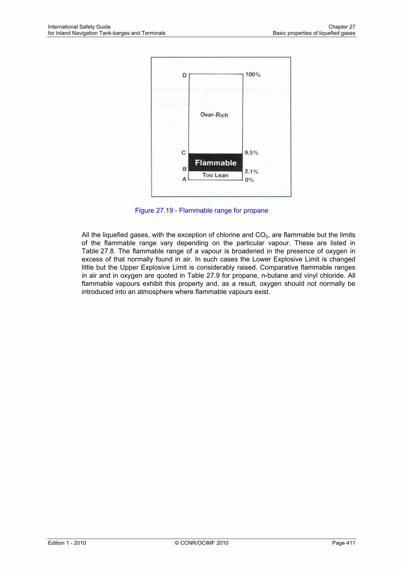
International Safety Guide Chapter 27 for Inland Navigation Tank-barges and Terminals Basic properties of liquefied gases
Edition 1 - 2010 © CCNR/OCIMF 2010 Page 411
Figure 27.19 - Flammable range for propane All the liquefied gases, with the exception of chlorine and CO2, are flammable but the limits of the flammable range vary depending on the particular vapour. These are listed in Table 27.8. The flammable range of a vapour is broadened in the presence of oxygen in excess of that normally found in air. In such cases the Lower Explosive Limit is changed little but the Upper Explosive Limit is considerably raised. Comparative flammable ranges in air and in oxygen are quoted in Table 27.9 for propane, n-butane and vinyl chloride. All flammable vapours exhibit this property and, as a result, oxygen should not normally be introduced into an atmosphere where flammable vapours exist.

International Safety Guide Chapter 27 for Inland Navigation Tank-barges and Terminals Basic properties of liquefied gases
Edition 1 - 2010 © CCNR/OCIMF 2010 Page 412
Liquefied gas Flashpoint
(°C)
Flammable range (% by vol. In air)
Auto-ignition Temperature (°C)
Methane - 175 5.3 – 14 595
Ethane - 125 3.0 – 12.5 510
Propane - 105 2.1 – 9.5 468
n-Butane - 60 1.5 – 9.0 365
i-Butane - 76 1.5 – 9.0 500
Ethylene - 150 3.0 – 34.0 453
Propylene - 108 2.0 – 11.1 453
∝-Butylene - 80 1.6 – 10 440
β-Butylene - 72 1.6 – 10 465
Butadiene - 60 1.1 – 12.5 418
Isoprene - 50 1.1 – 9.7 220
Vinyl Chloride - 78 4.0 – 33.0 472
Eyhylene Oxide - 18 3.0 – 100 429
Propylene Oxide - 57 14 – 28 465
Ammonia - 57 14 – 28 615
Chlorine Non-flammable
Carbon dioxide (CO2)
Non-flammable
Table 27.8 - Ignition properties for liquefied gases
Flammable range (% by volume)
(In air) (In oxygen)
Propane 2.1 – 9.5 2.1 – 55.0
n-Butane 1.5 – 9.0 1.8 – 49.0
Vinyl Chloride 4.0 – 33.0 4.0 – 70.0
Table 27.9 - Flammability range in air and oxygen for some liquefied gases
Flash Point The flash point of a liquid is the lowest temperature at which that liquid will evolve sufficient vapour to form a flammable mixture with air. High vapour pressure liquids such as liquefied gases have extremely low flash points, as seen from Table 27.8. However, although liquefied gases are never carried at temperatures below their flash point, the vapour spaces above such cargoes are non-flammable since they are filled entirely with cargo vapour and are thus safely above the Upper Explosive Limit.

International Safety Guide Chapter 27 for Inland Navigation Tank-barges and Terminals Basic properties of liquefied gases
Edition 1 - 2010 © CCNR/OCIMF 2010 Page 413
Auto-ignition Temperature The auto-ignition temperature of a substance is the temperature to which its vapour-in-air mixture must be heated to ignite spontaneously. The auto-ignition temperature is not related to the vapour pressure or to the flash point of the substance and, since the most likely ignition sources are external flames or sparks, it is the flash point rather than the auto-ignition temperature which is used for the flammability classification of hazardous materials. Nevertheless, when vapour escapes are considered in relation to adjacent steam pipes or other hot surfaces, the auto-ignition temperature is worthy of note. Accordingly, they are listed in Table 27.8. Energy Required for Ignition Accidental sources of ignition of a flammable vapour can be flames, thermal sparks (due to metal-to-metal impact) and electric arcs or sparks. The minimum ignition energy necessary to set fire to hydrocarbon vapours is very low, particularly when the vapour concentration is in the middle of the flammable range. Minimum ignition energies for flammable vapours in air are typically less than one millijoule. This is an energy level substantially exceeded by any visible flame, by most electric circuit sparks or by electrostatic discharges down to the lowest level detectable by human contact. The presence of oxygen in excess of its normal proportion in air further lowers the minimum ignition energy. Only the flammable mixtures of ammonia have minimum ignition energies Iying outside this typical range. Ammonia requires energies some 600 times higher than the other gases for ignition. Nevertheless, the possibility of ignition of ammonia vapours cannot be completely discounted. Flammability within Vapour Clouds Should a liquefied gas be spilled in an open space, the liquid will rapidly evaporate to produce a vapour cloud (see also Section 27.12.2) which will gradually disperse downwind. The vapour cloud or plume is flammable only over part of its area. The situation is illustrated in Figure 27.20.

International Safety Guide Chapter 27 for Inland Navigation Tank-barges and Terminals Basic properties of liquefied gases
Edition 1 - 2010 © CCNR/OCIMF 2010 Page 414
The region (B) immediately adjacent to the spill area (A) is non-flammable because it is over-rich. It contains too low a percentage of oxygen to be flammable. Region (D) is also non-flammable because it is too lean; containing too little vapour to be flammable. The flammable zone lies between these two regions as indicated by (C).
Figure 27.20 - Flammable vapour zones — a liquefied gas spill
27.23 Suppression of Flammability by Inert Gas
Whereas increasing the oxygen concentration in a flammable mixture causes a broadening of the flammable range and a lowering of the energy necessary for ignition, decreasing the oxygen causes the flammable range to be narrowed and the minimum ignition energy to be increased. If the oxygen availability is reduced to a sufficient extent, the mixture will become non-flammable no matter what the combustible vapour content may be. Figure 27.21 illustrates this concept for typical hydrocarbon gas mixtures with air and nitrogen. The mixtures are represented on the horizontal axis by the percentage oxygen content in the total mixture. The diagram provides much useful information. The narrowing of the flammable range as the oxygen is reduced can be seen from the shape of the area labelled flammable. It is also clear that an oxygen content of less than that at the left hand extremity of the flammable envelope renders the mixture non-flammable. This value, for most hydrocarbon vapours, is around 10 to 12 per cent by volume. However, on a gas carrier for an atmosphere to be adequately non-flammable, less than 5 per cent (sometimes 2 per cent) by volume oxygen is needed. This allows for a degree of poor mixing and pockets of gas remaining in some areas of the tank.

International Safety Guide Chapter 27 for Inland Navigation Tank-barges and Terminals Basic properties of liquefied gases
Edition 1 - 2010 © CCNR/OCIMF 2010 Page 415
Figure 27.21 - Flammable limits of gas mixtures in air and nitrogen
The diagram is also useful in illustrating proper inerting and gas-freeing procedures. For example, assume that a tank atmosphere is determined to be at point A. If the tank is then gas-freed directly with air, the composition of the tank atmosphere will move along the line AB to the fully gas-free condition at point B. In so doing, the atmosphere passes through the flammable envelope. This can be avoided by first inerting the tank along, say, the line AC to a point below the critical dilution line. Aerating to point B may then be undertaken without the tank atmosphere passing through the flammable envelope. This result can only be safely achieved if regular measurements are taken, using properly calibrated instruments to evaluate the atmosphere throughout the tank at the various stages. In this process, it is important to use reasonable margins of safety since the shape of the flammable envelope is ill-defined for mixtures and any non-homogeneity of the tank atmosphere must be allowed for. Also, the varying range of flammable limits for the different gases must be considered (see Table 27.8).

International Safety Guide Chapter 27 for Inland Navigation Tank-barges and Terminals Basic properties of liquefied gases
Edition 1 - 2010 © CCNR/OCIMF 2010 Page 416
27.24 Sources of Ignition
Reference should be made to section 4.2 for information on the control of potential ignition sources.

International Safety Guide Chapter 28 for Inland Navigation Tank-barges and Terminals Hazards of gases
Edition 1 - 2010 © CCNR/OCIMF 2010 Page 417
Chapter 28
HAZARDS OF GASES This Chapter mainly concentrates on the quality of the atmosphere to which personnel can be exposed. In addition to the risk to personnel encountering hydrocarbon vapours of a toxic nature, the question of oxygen deficiency is also covered. Methods of checking atmospheres are described. 28.1 Cargo Hazards
All gas carriers are designed so that, in normal operation, personnel should never be exposed to the hazards posed by the products being carried. This assumes, of course, that the tanker and its equipment are maintained properly and that operating instructions are followed. In the event of accidental leakage, emergency inspections or maintenance tasks, personnel may be exposed to liquid or gaseous product. It is the purpose of this Chapter to review the hazards to health and safety which such circumstances present and to outline means of hazard avoidance. The overall approach in the avoidance of hazards to personnel should always be, in order of preference: • Hazard removal, • Hazard control, and then only • Reliance on personal protection. This listing suggests that reliance of personal protection should only be used in cases where hazard removal or hazard control are found impossible to accomplish. An essential requirement is the thorough training of all personnel. Effective supervision of all tasks where hazards may be present is also vital. Training should go beyond basic instruction on the use of equipment or the execution of procedures, and should include the nature of the hazards, including those which are sometimes not immediately obvious. Broadly, the hazards of liquefied gases or their vapours may be five-fold. These hazards are discussed more fully later in this Chapter. However, the essential components are listed below:- • Flammability - see Section 28.2. • Toxicity (poisoning) - see Section 28.3.1. • Asphyxia (suffocation) - see Section 28.3.2. • Low temperature (frostbite) - see Section 28.4. • Chemical burns - see Section 28.5.

International Safety Guide Chapter 28 for Inland Navigation Tank-barges and Terminals Hazards of gases
Edition 1 - 2010 © CCNR/OCIMF 2010 Page 418
In Chapter 27, a description is given of the properties of the liquefied gas cargoes normally carried. In addition, the Cargo Information Data Sheets or MSDS provide detailed health and safety data for products. The risks of flammability, low temperature and asphyxia apply to nearly all liquefied gas cargoes. However, the hazard of toxicity and chemical burns apply to only some of them. Table 28.1 lists the main liquefied gases together with their flammable and toxic hazards. Where appropriate, asphyxiant hazards are also noted in the column headed 'TLV'. However, this applies only when the gas has asphyxiant hazards and is not recorded as having any toxic effects or where the toxic effects are limited. The table is subdivided horizontally by a double line. The products above this line are mainly the hydrocarbon liquefied gases and those below the line are mainly chemical gases. It should be noted that the chemical gases tend to have stronger toxic effects.
Table 28.1 - Health data - cargo vapour
Cargo vapour in air Toxic effects of vapour or liquid
Substance Flammable Toxic Typical TLV – TWA (ppm)
Corrosive/ Irritant
Effects on Nervous Systems
Methane Yes - A No -
Ethane Yes - A No Yes
Propane Yes - A No Yes
Butane Yes - 600 No Yes
Ethylene Yes - A No Yes
Propylene Yes - A No Yes
Butylene Yes - 800 No Yes
Isoprene Yes - No data No Yes
Butadiene Yes Yes 10 Yes yes
Ammonia Limited Yes 25 Very -
Vinyl Chlorine Yes Yes 5 Yes Yes
Ethylene Oxide Yes Yes 10 Very Yes
Propylene Oxide Yes Yes 50 Very Yes
Chlorine No Yes 25 Very Very
Gases shown with an ‘A’ mark in the ‘TLV’ column do not have recorded TLVs. These gases are relatively non- toxic in character. They are known as Asphyxiant Gases and will kill when their concentration in air is sufficient to displace the oxygen needed to sustain life (see 28.3.2)

International Safety Guide Chapter 28 for Inland Navigation Tank-barges and Terminals Hazards of gases
Edition 1 - 2010 © CCNR/OCIMF 2010 Page 419
The last two columns of the table show how a liquefied gas may affect a person. Broadly, the initial toxic effects on the human body can be corrosive or narcotic (effects on the nervous system). In certain cases, both may apply. In the case of a corrosive compound, depending on exposure and toxicity, its effects may be minor or major. In the case of minor effects, only limited irritation of the skin, eyes or mucous membranes may be felt. An example of a more serious case may be that debilitating effects on the lungs are experienced. In the case of exposure to a narcotic gas, the major initial effect is on the body's nervous system. In such cases, severe disorientation and mental confusion can result. The corrosive and narcotic effects are worthy of note. They are of help in identifying the gas to which a person has been exposed and, additionally, they help in identifying proper medical treatment (see Section 28.3.3).
Cargo Inhibitors Toxic effects
Substances Flammable Toxic Typical TLV-TWA
(ppm)
Corrosive/ Irritant
Effects on nervoeus system
Hydroquinone Limited Yes 1 Very Yes
Tertial butyl catechol Limited Yes - Very - Table 28.1(a) - Health data - cargo inhibitors
Table 28.1(a) provides similar information to that shown in Table 28.1 but covers the potential hazards of cargo inhibitors. Information on the type of inhibitor used in particular cargoes is given in Section 27.8.
Substance Frostbite Chemical burn
Methane Yes -
Ethane Yes -
Propane Yes -
Butane Yes -
Ethylene Yes -
Propylene Yes -
Butylene Yes -
Isoprene Yes -
Butadiene Yes -
Ammonia Yes Yes
Vinyl Chlorine Yes -
Etylene oxide Yes Yes
Propylene oxide Yes Yes
Chlorine Yes Yes
Table 28.2 - Additional health data - cargo liquid (effects on the human body) Cargo inhibitors
This information is discussed further in Sections 28.4 and 28.5.

International Safety Guide Chapter 28 for Inland Navigation Tank-barges and Terminals Hazards of gases
Edition 1 - 2010 © CCNR/OCIMF 2010 Page 420
28.2 Flammability
28.2.1 Operational Aspects
The single most hazardous aspect of liquefied gases is the flammable nature of their vapours. Much effort is put into tanker design to ensure effective cargo containment to avoid vapours escaping to atmosphere. In addition, tankers and terminals have design specifications for electrical equipment so as to ensure that, within well-defined operating zones, such sources of ignition are eliminated. Furthermore, in the tanker and terminal working environments, operational procedures should apply that limit other possible sources of ignition, such as those described in Section 27.24, to areas outside established safe distances (see also Section 28.2.2). All liquefied gases transported in bulk by inland waterways with the exception of chlorine and CO2, are flammable. The vapours of other liquefied gases are easily ignited. The exception to this is ammonia which requires much higher ignition energy than the other flammable vapours. Accordingly, fires following ammonia leakage are less likely than with the other cargoes. However, in practice, it is usual to consider the possibility of ammonia ignition and to act accordingly.
28.2.2 Emergency Aspects Because of the very rapid vaporisation of spilled liquefied gases, the spread of flammable vapour will be far more extensive than in the case of a similar spillage of oil. The chances of ignition following a spill of liquefied gas is, therefore, much greater. For this reason, many terminals establish ignition-free zones round jetties. The extent of these zones is based on a hazard analysis, taking into account local conditions and involving the dimensions of the gas cloud which could be so formed. To establish the size of such a cloud, it is necessary first to estimate the size of the maximum credible spillage. Such an estimation may be carried out in various ways and numerous methods are available. One simplified method is published in the SIGTTO publication Guidelines for Hazard Analysis. Results of such estimations at jetties often show the need for safety distances in the order of several hundred metres. The hazards to personnel in fighting oil cargo fires are well known and apply generally to liquefied gas fires. There are, however, some points of difference to note (see Sections 27.22, 27.23 and 27.24). Radiation from liquefied gas fires, because of the rapidity of vapour production, can be intense and fire-fighting should only be attempted when personnel are wearing protective clothing suited for purpose.
28.3 Air Deficiency
28.3.1 Toxicity General Toxicity is the ability of a substance to cause damage to living tissue, including impairment of the nervous system. Illness or, in extreme cases, death may occur when a dangerous gas or liquid is breathed, taken orally or absorbed through the skin. (In general, the terms 'toxic' and 'poisonous' can be considered synonymous.)

International Safety Guide Chapter 28 for Inland Navigation Tank-barges and Terminals Hazards of gases
Edition 1 - 2010 © CCNR/OCIMF 2010 Page 421
Some liquefied gases present toxic hazards, principally if the vapours are inhaled. Ammonia, chlorine, ethylene oxide and propylene oxide, are also very corrosive to the skin. Vinyl chloride is known to cause cancer and butadiene is suspected as having similar harmful effects. Incomplete combustion of hydrocarbon vapours may produce the toxic gas carbon monoxide which is found in inert gas in quantities which can vary with the quality of combustion in the generator. Combustion of vinyl chloride may produce toxic carbonyl chloride (also called phosgene). Many substances can act as poisons and a person can be exposed to their effects by various routes. As a result, toxicology has branched into several specialised areas, one of which is industrial toxicology. In this area, the effects of chemicals in the air or on the body are evaluated. Toxic substances are often ranked according to a system of toxicity ratings. One such scale is shown below: Unknown, for products with insufficient toxicity data available; No toxicity, for products causing no harm (under conditions of normal use) or for those that produce toxic effects only because of overwhelming dosages; Slight toxicity, for products producing only slight effects on the skin or mucous membranes or other body organs; Moderate toxicity, for products producing moderate effects on the skin or mucous membranes or other body organs from either acute or chronic exposure; and, Severe toxicity, for products that threaten life or cause permanent physical impairment or disfigurement from either acute or chronic exposure. In summary, toxic substances may result in one or more of the following effects: 1. Permanent damage to the body: With a few chemicals, such serious ill-effects may
occur. Vinyl chloride is a known human carcinogen and butadiene is suspected of having similar effects.
2. Narcotics: A patient suffering from exposure to a narcotic product can be oblivious to the dangers around him. Narcosis results in ill-effects to the nervous system. The sensations are blunted, clumsy body movements are noticeable and distorted reasoning occurs. Prolonged exposure to a narcotic may result in loss of consciousness.
3. Corrosion/lrritation of the skin, lungs, throat and eyes. Threshold Limit Values (TLV) Research into toxicity considers such factors as:- • The length of exposure. • Whether contact is by inhalation, ingestion or through the skin. • The stress of the person, and • The toxicity of the product.

International Safety Guide Chapter 28 for Inland Navigation Tank-barges and Terminals Hazards of gases
Edition 1 - 2010 © CCNR/OCIMF 2010 Page 422
As a guide to permissible vapour concentrations in air, such as might occur in terminal operation, various government authorities publish systems of Threshold Limit Values (TLVs). These systems cover many of the toxic substances handled by the gas industry. The TLVs, as published, are usually quoted in ppm (parts per million of vapour-in-air by volume) but may be quoted in mg/m3 (milligrams of substance per cubic metre of air). TLVs-TWA (see definitions below) for the main liquefied gases are given in Table 28.1. These are provided for purposes of illustration and help to identify the relative toxicity of vapours. However, it must be appreciated that the application of a specific TLV to the workplace is a specialist matter. It is not just the safe level which must be known; it is also the resultant effect on the body which must be understood. The most widely quoted TLV system is that of the American Conference of Governmental Industrial Hygienists (ACGIH). TLV systems promulgated by advisory bodies in other countries are generally similar in structure. The TLVs in most systems are republished annually and updated in light of new knowledge. The latest revision of these values should be made known to operating personnel by their management. The ACGIH system contains the following three categories of TLVs which describe the concentration in air to which it is believed personnel may be exposed, under certain specific circumstances, without adverse effects: (1) TLV-TWA. This is known as the Time Weighted Average. It is the concentration of
vapour-in-air which may be experienced for an eight-hour day or 40-hour week throughout a person's working life. It is the most commonly quoted TLV. It shows the smallest concentration (in comparison to (2) and (3) below) and is the value reproduced in Table 28.1.
(2) TLV-STEL. This is known as the Short Term Exposure Limit. It is the maximum
concentration of vapour-in-air allowable for a period of up to 15 minutes provided there are no more than four exposures per day and at least one hour between each. It is always greater than (1) above but is not given for all vapours.
(3) TLV-C. This is what is known as the Ceiling concentration of the vapour-in-air which
should never be exceeded. Only those substances which are predominantly fast-acting are given a TLV-C. Of the main liquefied gases only the more toxic products, such as ammonia and chlorine, have been ascribed such a figure.
As explained earlier in this Section, TLVs should not be regarded as absolute dividing lines between safe and hazardous conditions. It is always good operating practice to keep all vapour concentrations to an absolute minimum so limiting personal exposure. It should be remembered that in some countries local legislation differs and this should not be ignored
28.3.2 Asphyxia (Suffocation) For survival, the human body requires air having a normal content of about 21 per cent oxygen. However, a gas-free atmosphere with somewhat less oxygen can support life for a period without ill-effects being noticed. The susceptibility of persons to reduced oxygen levels vary but at levels below about 19 per cent, impaired mobility and mental confusion rapidly occur. This mental confusion is particularly dangerous as the victim may be unable to appreciate his predicament. Accordingly, self-assisted escape from a hazardous location may be impossible. At levels below 16 per cent, unconsciousness takes place rapidly and, if the victim is not removed quickly, permanent brain damage and death will result.

International Safety Guide Chapter 28 for Inland Navigation Tank-barges and Terminals Hazards of gases
Edition 1 - 2010 © CCNR/OCIMF 2010 Page 423
In general, such a problem is limited to enclosed spaces. Oxygen deficiency in an enclosed space can occur with any of the following conditions:- • When large quantities of cargo vapour are present. • When large quantities of inert gas or nitrogen are present, and • Where rusting of internal tank surfaces has taken place. For the above reasons, it is essential to prohibit entry to any space until an oxygen content of 20.9 per cent is established. This can be assured by using an oxygen analyser and sampling the atmosphere from a number of points. These should be at different levels and widely dispersed within the space. As appropriate for the space being entered, tests for hydrocarbon gas and carbon monoxide may also be required (see Section10.3). With regard to Table 28.1, it will be seen from the footnote that some gases are known as asphyxiant gases. This is because they have limited toxic side effects but can be dangerous if present in sufficient quantities so as to exclude oxygen. Accordingly, a casualty having been exposed to these products is likely to be suffering from suffocation. Immediate action is necessary in such cases as outlined in Section 28.3.3. If tank entry is absolutely necessary and the above gas-free condition cannot be ensured, personnel entering the space must be protected by breathing apparatus and should follow the advice given in Section 10.7.
28.3.3 Medical Treatment The symptoms and medical treatment for casualties of asphyxia or from the effects of toxic materials are summarised in this Section. Medical treatment for exposure to gas first involves the removal of the casualty to a safe area. Where necessary it may also involve artificial respiration, external cardiac massage and the administration of oxygen. Professional medical treatment should always be sought in cases where casualties have been overcome by gas. Further advice on these issues is available from the material’s data sheets and if available, in the Medical First Aid Guide (MFAG) published by IMO. The later publication has a number of Chemical Tables associated with it. These tables categorise the main liquefied gases into groups as shown in Table 28.3.

International Safety Guide Chapter 28 for Inland Navigation Tank-barges and Terminals Hazards of gases
Edition 1 - 2010 © CCNR/OCIMF 2010 Page 424
Table 28.3 - Liquefied Gas groups - for medicial first aid purposes In the MFAG, each of the main categorisations (as listed along the top row of Table 28.3) has medical first-aid advice attached to it. This is divided into general advice, signs and symptoms and treatment. If a person is affected by any of the gases listed, it is the tables in the MFAG which should be consulted. With regard to medical treatment, the MFAG has recommended advice for:- • Inhalation; • Skin contact; • Eye contact, and • Ingestion. The main points to be remembered in treating patients for gas poisoning or asphyxiation are outlined below (other points are covered later): Treatment for asphyxia and inhalation of toxic fumes Remove the casualty at once from the dangerous atmosphere - ensure that rescuers are equipped with self-contained breathing apparatus so that they do not become the next casualty.
MFAG TABLE
310 Hydrocarbons
340 Chlorinated hydrocarbons
365 Alipatic oxides
620 Liquefied gases
725 Ammonia
740 Chlorine
Butadiene Vinyl chlorine Ethylene oxide Methane Ammonia Chlorine
Butane Propylene oxide
Butylene
Ethane
Ethylene
Propane
P R O D U C T
Propylene

International Safety Guide Chapter 28 for Inland Navigation Tank-barges and Terminals Hazards of gases
Edition 1 - 2010 © CCNR/OCIMF 2010 Page 425
To check that the patient is breathing tilt the head firmly backwards as far as it will go to relieve obstructions and listen for breathing with the rescuer's ear over the patient's nose and mouth.
Patient not breathing:
• Give artificial respiration at once
• Give cardiac compression if the pulse is absent
Patient breathing but unconscious:
• Place the patient in the unconscious position
• Check there are no obstructions in the mouth
• Remove any dentures
• Insert an Airway; leave in place until the patient regains consciousness
• Give oxygen. (See the sub-section which follows)
• Keep the patient warm
• Give nothing by mouth
• Give no alcohol, morphine or stimulant
Patient conscious but having breathing difficulty:
• Place the patient in a high sitting-up position and keep warm
• Give oxygen. (See the sub-section which follows)
If breathing does not improve despite these measures, then asphyxia or other lung problems may have occurred. In such circumstances, or if the patient's condition deteriorates rapidly, obtain medical advice.

International Safety Guide Chapter 28 for Inland Navigation Tank-barges and Terminals Hazards of gases
Edition 1 - 2010 © CCNR/OCIMF 2010 Page 426
28.3.4 Oxygen Therapy
Oxygen resuscitators Oxygen resuscitators are used to provide oxygen-enriched respiration to assist in the recovery of victims overcome by oxygen deficiency or toxic gas. The equipment can be taken into enclosed spaces to give immediate treatment to a casualty. Oxygen resuscitators consist of a face mask, pressurised oxygen cylinder and automatic controls to avoid damage to the victim and give audible warning in the event of airway obstructions. The equipment is provided with a standard eight-metre long extension hose so that the carrying case (with cylinder and controls) may be securely placed and the mask taken to the victim if he is lying in a confined location. Some tankers provide a further 15 metre extension hose. If the equipment is taken into a contaminated atmosphere, it must be remembered that, if adjustable, the instrument must be set to supply only pure oxygen. Caution with its use in a flammable atmosphere is necessary. If the instrument is used when the victim has been removed from the contaminated space, there are means to vary the air/oxygen mix.
It should be noted that the couplings on oxygen resuscitators should not be greased.
Warning: Smoking, naked light or fires must not be allowed in the same room during the administration of oxygen because of the risk of fire.
Oxygen must be given with care since it can be dangerous to patients who have had breathing difficulties such as bronchitis. An accident in which a patient may require oxygen can be divided into two stages: Stage 1 - During rescue During rescue the patient should be connected to the portable oxygen resuscitation apparatus and oxygen administered until transferred to safety.
Stage 2 - When the patient is in a safe room The unconscious patient 1. Ensure there is a clear passage to the lungs and that an Airway is in place. 2. Place mask over the nose and mouth and give 35 per cent oxygen. 3. Connect the mask to the flowmeter and set it at 4 litres per minute.
The conscious patient 1. Ask if the patient suffers with breathing difficulty. If the patient has severe bronchitis,
then give only 24 per cent oxygen. All others should be given 35 per cent oxygen. 2. The mask is secured over the patient's mouth and nose. 3. The patient should be placed in the high sitting-up position. 4. Turn on the oxygen flowmeter to 4 litres per minute.

International Safety Guide Chapter 28 for Inland Navigation Tank-barges and Terminals Hazards of gases
Edition 1 - 2010 © CCNR/OCIMF 2010 Page 427
Oxygen therapy should be continued until the patient no longer has difficulty in breathing and has a healthy colour. If the patient has difficulty in breathing, or if the face, hands and lips remain blue for longer than 20 minutes, seek urgent medical assistance. Additional measures necessary where exposure to toxic vapours has been experienced include:- • The removal of affected clothing. • Eye washing, and • Skin washing.
28.4 Frostbite The extreme coldness of some liquefied gases is, in itself, a significant hazard. If the skin is exposed to severe cold, the tissue becomes frozen. This danger is ever-present in gas terminals and on a tanker handling fully refrigerated cargoes. For fully pressurised gases, while containment systems will normally be at or near ambient temperature, liquid leaks will quickly flash to the fully refrigerated temperature. Such areas should never be approached without proper protective clothing. The symptoms of frostbite are extreme pain in the affected area (after thawing), confusion, agitation and possibly fainting. If the affected area is large, severe shock will develop. Initial symptoms • The skin initially becomes red, but then turns white; • The affected area is usually painless, and • The affected area is hard to the touch. • If the area is left untreated, the tissue will die and gangrene may occur. Treatment • Warm the area quickly by placing it in water at 42 °C until it has thawed.* • Keep the patient in a warm room. • Do not massage the affected area. • Severe pain may occur on thawing: give pain killer or morphine if serious. • Blisters should never be cut, nor clothing removed if it is adhering firmly. • Dress the area with sterile dry gauze. • If the area does not regain normal colour and sensation, obtain medical advice. * As immediate action is necessary, and without the warm water close to hand, in the
first instance the affected part can be warmed with body heat or woollen material. If the finger or hand has been affected, the casualty should hold his hand under his armpit. Blood circulation should be allowed to re-establish itself naturally. If appropriate, the casualty should be encouraged to exercise the affected part while it is being warmed.

International Safety Guide Chapter 28 for Inland Navigation Tank-barges and Terminals Hazards of gases
Edition 1 - 2010 © CCNR/OCIMF 2010 Page 428
28.5 Chemical Burns
As shown in Table 28.2, chemical burns can be caused by ammonia, chlorine, ethylene oxide and propylene oxide. The symptoms are similar to burns by fire, except that the product may be absorbed through the skin causing toxic side-effects. Chemical burning is particularly damaging to the eyes. Symptoms • A burning pain with redness of the skin. • An irritating rash. • Blistering or loss of skin. • Toxic poisoning. Treatment • Attend first to the eyes and skin. • Wash the eyes thoroughly for ten minutes with copious amounts of fresh water. • Wash the skin thoroughly for ten minutes with copious amounts of fresh water. • Cover with a sterile dressing. Otherwise, the treatment is as for burns, details of which are contained in the IMO Medical First Aid Guide. On gas carriers authorised to transport these products, deck showers and eye baths are provided for water dousing; their locations should be clearly indicated.
28.6 Transport to Hospital
It is extremely important to label the patient adequately before removal from the tanker or terminal and a specimen patient-label is shown in Figure 28.1.
For the guidance of Medical Officer
1. Name of Patient ................................................................... Age ................................ Home Address ................................................................................................................... ............................................................................................................................................ ............................................................................................................................................ Name of Tanker ............................... Port ................. Next Port ............................. Name and Address of Shipowner and Ship's Agent ............................................................................................................................................ ............................................................................................................................................
2. Above person was exposed to .................................................................... gas
at (Time) ...................................... on (Date) ...................................................... 3. Brief summary of first aid treatment given
............................................................................................................................................
............................................................................................................................................
Figure 28.1 - Patient label

International Safety Guide Chapter 28 for Inland Navigation Tank-barges and Terminals Hazards of gases
Edition 1 - 2010 © CCNR/OCIMF 2010 Page 429
28.7 Hazardous Atmospheres
28.7.1 The Need for Gas Testing
The atmosphere in enclosed spaces must be tested for oxygen, explosive and toxic contents in the following circumstances: • Prior to entry by personnel (with or without protective equipment). • During gas-freeing, inerting and gassing-up operations. • As a quality control before changing cargoes, and • To establish a gas-free condition prior to drydock or tanker repair yard. The atmosphere in a cargo tank is rarely, if ever, homogeneous. With the exception of ammonia and methane, most cargo vapours at ambient temperatures are denser than air. This can result in layering within the cargo tank. In addition, internal structures can hold local pockets of gas. Thus, whenever possible, samples should be drawn from several positions within the tank. Atmospheres which are inert or deficient in oxygen cannot be checked for flammable vapours with a combustible gas indicator. Therefore, oxygen concentrations should be checked first, followed by checks for flammable and then toxic substances. All electrical instruments used should be approved as intrinsically safe.
28.7.2 Oxygen Analysers Several different types of oxygen analyser are available and reference should be made to Sections 2.4.9 and 2.4.10 for a description of typical analysers that are in use.
28.7.3 Combustible Gas Indicators Descriptions of various types of combustible gas indicators are provided in Section 2.4 which should be referenced for further information.
28.7.4 Toxicity Detectors Reference should be made to Section 2.4.7 for a description of toxic gas detectors.

International Safety Guide Chapter 28 for Inland Navigation Tank-barges and Terminals Hazards of gases
Edition 1 - 2010 © CCNR/OCIMF 2010 Page 430
International Safety Guide Chapter 29 for Inland Navigation Tank-barges and Terminals Static electricity
Edition 1 - 2010 © CCNR/OCIMF 2010 Page 431
Chapter 29
STATIC ELECTRICITY This Chapter describes hazards associated with the generation of static electricity. The risks presented by static electricity discharges occur where a flammable atmosphere is likely to be present. 29.1 Electrostatics
As is the case with many other hydrocarbon liquids, a static electrical charge can be built up within a liquefied gas as it is being pumped. It has been found that the charge will increase as pumping velocity rises. This phenomenon occurs due to charge separation between layers within the fluid. The charge is then retained for some time within the liquid mass by its non-conducting property. The danger of such charges is that they can attain sufficient potential to create incendive sparks and, particularly in cargo tanks, electrical arcing is possible. It is, therefore, vital that the handling of gas cargoes only takes place in spaces having atmospheres outside the flammable range. On gas carriers, such atmospheres are always maintained in the over-rich condition. Problems with static electricity can also arise within vapour flows but only when the gas is contaminated with debris, dust particles or when a condensed mist is present. In such cases it is the debris (or the mist which forms as it exits to atmosphere) which attains a static charge. Vapours which can attain a static charge in this way include carbon dioxide (as a fire extinguishing agent) and steam. Liquid hydrocarbons which are most prone to static build-up are called static accumulators. Reference should also be made to the guidance given in Chapter 3 ‘Static Electricity’.

International Safety Guide Chapter 29 for Inland Navigation Tank-barges and Terminals Static electricity
Edition 1 - 2010 © CCNR/OCIMF 2010 Page 432

International Safety Guide Chapter 30 for Inland Navigation Tank-barges and Terminals Fire-fighting
Edition 1 - 2010 © CCNR/OCIMF 2010 Page 433
Chapter 30
FIRE-FIGHTING This Chapter discusses events which may follow cargo spillage and the procedures which can be adopted to protect life and property in such circumstances. It also describes the types of fire that may be encountered on a gas tanker. 30.1 The Principal Hazards
The gases with which this Guide is concerned are either flammable or toxic or both. Most are stored and handled at sub-zero temperatures, or under pressure or by means of a combination of the two. The main hazards are, therefore, vapour release, flammability, toxicity and the effects of sub-zero temperatures on personnel and structures.
30.1.1 Flammability
As already described in Section 27.22, when a gas is released to atmosphere, if within its flammable range and if exposed to a source of ignition, it will burn. Depending upon the conditions under which combustion takes place, some degree of over-pressure will occur due to the rapid expansion of the heated gas. A liquid spill or vapour cloud burning over open water will develop little over-pressure due to the unconfined nature of the surroundings. At the other extreme, the ignition of vapour within an enclosed space will rapidly create an over-pressure sufficient to burst the boundaries. Between these two extremes, that is in cases of partial confinement such as might occur among shore plant and equipment, ignition may produce over-pressures sufficient to cause substantial damage, so escalating the hazard and its consequences. A leakage of liquid or vapour from a pipeline under pressure will burn, if ignited, as a jet which will continue as long as fuel is supplied. A particularly destructive form of vapour burn, associated with the storage of liquefied gas in pressurised containers, is the BLEVE (Boiling Liquid Expanding Vapour Explosion). This is described in 27.22.

International Safety Guide Chapter 30 for Inland Navigation Tank-barges and Terminals Fire-fighting
Edition 1 - 2010 © CCNR/OCIMF 2010 Page 434
30.2 Liquefied Gas Fires
30.2.1 General
It is not proposed in this Guide to deal with fires that can occur in terminal buildings, store rooms, the tanker's accommodation or machinery spaces. The characteristics and methods of fighting such fires are covered elsewhere. Provided cargo containment is not ruptured, it is rare for such fires to spread to the cargo. Accordingly, this section deals only with cargo liquid or vapour fires.
Cargo-related fires may be broadly categorised as follows: • Jet fires from leaks at pumps or pipelines, • Fires from confined liquid pools, • Fire, from unconfined spillages, • Fires in enclosed spaces, such as compressor rooms and • Manifold fires.
30.2.2 Jet Fires
Small leaks from pump glands, pipe flanges or from vent risers will initially produce vapour. This vapour will not ignite spontaneously but, if the escape is large, there may be a risk of the vapour cloud spreading to a source of ignition. Should a gas cloud occur, ignition should be prevented by closing all openings to hazardous areas. Furthermore, the vapour cloud should be directed or dispersed away from ignition sources by means of fixed or mobile water sprays (see 30.3.1). If ignition does occur, it will almost certainly flash back to the leak. Leaks from pipelines are likely to be under pressure and, if ignited, will give rise to a jet flame. Emergency shut-down of pumping systems and closure of ESD valves should have already occurred but, even so, pressure may persist in a closed pipeline until the liquid trapped within has been expelled through the leak. In such a case, the best course of action is often to allow the fire to burn out. The alternative of extinguishing the fire has a high risk of further vapour cloud production and flash-back causing re-ignition. While the fire is being allowed to burn itself out, the surroundings should be protected with cooling water.
30.2.3 Liquid (pool) Fires
Significant pool fires are not likely on tankers' decks because the amount of liquid which can be spilled in such a location is limited. The arrangement of the tanker's deck, with its camber and open scuppers, will allow liquid spillage to flow quickly and freely away over the tanker's side. In case of cargo leakage, open scuppers on gas carriers are an important feature to allow cold liquids to escape quickly so reducing the risk of metal embrittlement and the possibility of small pool fires on a tanker’s deck. Prompt initiation of ESD procedures further limits the availability of liquid cargo.

International Safety Guide Chapter 30 for Inland Navigation Tank-barges and Terminals Fire-fighting
Edition 1 - 2010 © CCNR/OCIMF 2010 Page 435
Figure 30.1 - Pool fire configurations
A liquid spillage on shore, from tank or pipeline ruptures, may involve large quantities but should be contained in bunded areas or culverts. Any ignition of the ensuing vapour cloud would then result in a pool fire. The flame height from such a fire, in the absence of wind, is as illustrated in Figure 30.1. Figure 30.1 also illustrates the effect of wind in deflecting the axis of the flame and in shortening flame-length. The emissive power of a flame surface increases with pool diameter. Heat radiation levels of LPG pool fires dictate that unprotected personnel must escape from the immediate vicinity as quickly as possible. Heat radiation from a fire falls away approximately as the inverse square of the distance between the object and the flame. The human body will feel extreme pain on bare skin after only 10 seconds of incident radiation of 6 kW/m2 and will suffer severe blistering after 10 seconds exposure to 10 kW/m2. Incident radiation greater than 10 kW/m2 will quickly vaporise PVC cables and will seriously affect fibreglass lifeboats. The estimation of safe distances from a pool fire involves complex factors but, for a large pool fire, such safe distances are likely to be some tens of metres. Because of the damage which radiation can inflict on surrounding tanks and plant, such equipment is always protected (often by insulation or by remotely operated water deluge systems). Also, the bunds and culverts where pool fires may occur are often provided with remotely operated dry powder installations. Alternatively, they may be fitted with a high expansion foam system for rapidly building up and maintaining a depth of foam to control the rate of burning.

International Safety Guide Chapter 30 for Inland Navigation Tank-barges and Terminals Fire-fighting
Edition 1 - 2010 © CCNR/OCIMF 2010 Page 436
30.2.4 Fires in Compressor Rooms
Enclosed spaces containing cargo plant such as compressors, heat exchangers or pumps will normally be provided with a fixed and remotely activated fire extinguishing system such as carbon dioxide. Provided no major disruption to the enclosure has occurred, these systems should be immediately effective.
30.2.5 Manifold Fires
Manifold fires may consist of a jet fire (see 30.2.2) as a result of leakage from the manifold flanges, or of a pool fire from a drip tray (see 30.2.3), although the amount of liquid in a drip tray is comparably small. Prompt initiation of ESD procedures further limits the availability of liquid cargo.
30.3 Liquefied Gas Fire-Fighting 30.3.1 Extinguishing Mediums
There are a number of established and proven methods for dealing with gas fires but, to be effective, the appropriate extinguishing medium must be used.
Water Water should never be applied to a burning liquefied gas pool. This would provide a heat source for more rapid vaporisation of the liquid and increase the rate of burning. Nevertheless, water remains a prime fire extinguishing medium for liquefied gas fire-fighting. Being abundantly available, water is an excellent cooling agent for surfaces exposed to radiation or direct fire impingement. Also, it may be used in spray form as a radiation screen to protect fire-fighters. In some circumstances, water can be used to extinguish a jet of burning gas but this is not always desirable. Fixed water deluge systems are customary for surfaces such as tankers' structures, deck tanks and piping, shore storage tanks, plant and jetties, all of which can be exposed to liquefied gas fires. Such systems are designed to supply a layer of water over the exposed surfaces and thus to provide a useful cooling effect. Provided a water layer of some thickness can be maintained, the surface temperature cannot exceed 100°C. Application rates vary with the distance of the structure to be protected from the envisaged fire source and range from two to ten or more litres of water per square metre of protected surface. Water spray from fixed monitors or from hand-held hose nozzles can provide radiation protection for personnel in their approach to shut-off valves. Additionally, they can provide protection when approaching jet fires in order to deliver more effectively an attack by dry chemicals to extinguish the flame. A special application of water sprayed from hoses is to deflect an unignited vapour cloud away from ignition sources.

International Safety Guide Chapter 30 for Inland Navigation Tank-barges and Terminals Fire-fighting
Edition 1 - 2010 © CCNR/OCIMF 2010 Page 437
Dry chemical powders Dry chemical powders such as sodium bicarbonate, potassium bicarbonate and urea potassium bicarbonate can be very effective in extinguishing small LPG fires. It is also usual for jetty manifold areas to be protected by substantial portable or fixed dry powder systems. Dry chemical powders are effective in dealing with gas fires on deck or in extinguishing jet fires from a holed pipeline and have been used successfully in extinguishing fires at vent risers. Dry chemicals attack the flame by the absorption of free radicals in the combustion process but have a negligible cooling effect. Re-ignition from adjacent hot surfaces, therefore, should be guarded against by cooling any hot areas with water before extinguishing the flame with dry powder. Foam High expansion foam, adequately applied to the surface of a burning liquid pool (when confined within a bunded area), suppresses the radiation from the flame into the liquid beneath and reduces the vaporisation rate. Consequently, the intensity of the pool fire is limited. Continuous application is required in order to maintain a foam depth of at least one to two metres. High expansion foam of about five-hundred to one expansion ratio has been found to be the most effective for this purpose. Foam, however, will not extinguish a liquefied gas fire and, while effective for the above purposes, requires to be applied to a substantial depth. For liquefied gases, therefore, foam is only appropriate for use in bunded areas and for this reason is only found at terminals and is not provided on gas carriers. Inert gas and carbon dioxide Inert gas or nitrogen is commonly used on gas carriers and in terminals for the permanent inerting of interbarrier spaces or for protective inerting of cargo-related spaces. These spaces can include tankers' hold spaces or enclosed plant spaces on shore which are normally air-filled but in which flammable gas may be detected. Because of the comparatively low rate at which such gas can be delivered, it is not normally used for the rapid inerting of an enclosed space in which a fire has already begun. For this, high-pressure bottled carbon dioxide gas or halon replacements is injected through multiple nozzles, the mechanical ventilation system to the space having been first shut off. While carbon dioxide injection systems are effective in enclosed spaces, they have two disadvantages. Their fire extinguishing action is achieved by displacing oxygen in the space to a level which will not support combustion and it is, therefore, essential that all personnel evacuate the space before injection begins. Secondly, the injection of CO2 produces electrostatic charging which can be an ignition hazard if CO2, is injected inadvertently or as a precautionary measure into a flammable atmosphere. CO2 or nitrogen injected into safety relief valve outlets may be used as an effective means of extinguishing vapour fires at the vent risers. This is particularly valuable once the initial pressure flow has subsided.

International Safety Guide Chapter 30 for Inland Navigation Tank-barges and Terminals Fire-fighting
Edition 1 - 2010 © CCNR/OCIMF 2010 Page 438
After CO2 has been injected into an enclosed space, the boundaries of the space should be kept cool - usually with water sprayed from a hose. The space should remain sealed until it is established that the fire is extinguished and has sufficiently cooled so that it will not re-ignite with the introduction of oxygen. Halon replacements Halon can now no longer be used, as there is a total ban on this CFC under the provisions of an international treaty. This is because it has a high Ozone Depletion Potential and is, thus, a danger to the environment. There has been considerable research into halon substitutes and replacement agents are now commercially available. For information on Halon replacements, reference should be made to Section 5.3.3.
30.3.2 Training For effective use of any of these systems, a thorough knowledge of the capabilities of each is essential. Speed in correctly tackling a fire is vital if escalation is to be minimised and life and property safeguarded. This knowledge can only be achieved by a serious approach to training by management and operating personnel alike. Training of ship and shore personnel who may have to lead a fire party should be given in shore-based fire schools where fire-extinguishing techniques can be demonstrated and practiced. The training should be consolidated by frequent exercises on board tanker and in terminals and these should be realistically staged. Proper maintenance of fire-fighting equipment is also of importance. Inspection and maintenance should be incorporated into on board and on-site training programmes and these aspects should help to familiarise personnel with the equipment and to provide them with a fuller understanding of its operation.

International Safety Guide Chapter 31 for Inland Navigation Tank-barges and Terminals Shipboard systems
Edition 1 - 2010 © CCNR/OCIMF 2010 Page 439
Chapter 31
SHIPBOARD SYSTEMS
This Chapter describes the principle tanker systems that are used during cargo and ballast operations in port It also covers gas carrier cargo handling equipment and related instrumentation. It reviews pipeline and valve design issues and considers cargo pumps and ancillary equipment. The plant associated with cargo reliquefaction is also described along with some of the special operational and maintenance issues. The design of inert gas generation equipment is also covered. 31.1 Cargo Pipelines and Valves 31.1.1 Cargo Pipelines
Gas carriers are fitted with liquid and vapour manifolds. These are connected to liquid and vapour headers — or pipelines — (see Figure 32.2) with branches leading into each cargo tank. The liquid loading line is led through the tank dome to the bottom of each cargo tank; the vapour connection is taken from the top of each cargo tank. On semi-pressurised and fully refrigerated LPG tankers a vapour connection is taken from the vapour header to the cargo compressor room where reliquefaction of the boil-off takes place. After reliquefaction the cargo is piped, via a condensate return line, to each cargo tank. Cargo pipelines are not allowed beneath deck level on gas carriers; therefore, all pipe connections to tanks must be taken through the cargo tank domes which penetrate the main deck. Vapour relief valves are also fitted on the tank domes; these are piped, via a vent header, to the vent riser. The vent risers are fitted at a safe height and safe distances from accommodation spaces and other such gas-safe zones as specified in the applicable Gas Codes. Provision must be made in the design and fitting of cargo pipelines to allow for thermal expansion and contraction. This is best achieved by the fitting of expansion loops or by using the natural geometry of the pipework, as appropriate. In a few specific cases, expansion bellows may be fitted and, where this is planned, corrosion resistant materials should be used. Where expansion bellows are fitted in vapour lines, it should be ensured that their pressure rating at least meets the liquid pipeline design criteria. The use of bellows in liquid lines is not recommended. Furthermore, expansion bellows are often subject to a considerable amount of wear and tear while a tanker is in service — in particular, sea-water corrosion must be carefully avoided otherwise pin hole leaks are liable to develop.

International Safety Guide Chapter 31 for Inland Navigation Tank-barges and Terminals Shipboard systems
Edition 1 - 2010 © CCNR/OCIMF 2010 Page 440
It is also important not to alter or adjust adjacent pipeline supports once the tanker has entered into service since they form an integral part of the expansion arrangements. Furthermore it should also be noted that parts of pipeline systems are fitted with strong anchor points to resist lateral or vertical displacement from surge pressures. Similarly, when replacing parts such as bolts and restraining rods, care must be taken to ensure that the new parts are of the correct material for the service. Removable spool pieces are taken in or out of pipelines to interconnect sections of line for special operational reasons such as using the inert gas plant or ensuring segregation of incompatible cargoes. These spool pieces should not be left in position after use but should be removed and pipelines blanked to ensure positive segregation.
31.1.2 Cargo Valves Isolating valves for cargo tanks must be provided in accordance with applicable Gas Codes. Where cargo tanks have a MARVS greater than 0.7 barg (Type ‘C’ tanks according to the IGC code), the liquid and vapour connections on the tank dome (except relief valve connections) should be fitted with a double valve arrangement. This should comprise one manually operated valve and a remotely operated isolation valve fitted in series. There are some possible exemptions: e.g. one manual valve and one excessive flow valve, or two manual valves. For very small sample points and gauge connections, it is possible to use only one valve; in this case an orifice should be in place to avoid excessive flow. Remotely operated emergency shut-down valves are provided at the liquid and vapour manifolds for all gas carriers. Figure 31.1 shows the piping system on a cargo tank dome including the valving arrangement. This particular drawing is typical for a semi-pressurised tanker. The types of isolation valve normally found on gas tankers are ball, globe, plug or butterfly valves. These valves are usually fitted with pneumatic or hydraulic actuators. Ball valves for liquefied gas service are provided with a means of internal pressure relief. This is usually a hole drilled between the ball cavity and the downstream side of the valve. Valves must be of the fail-safe type.

International Safety Guide Chapter 31 for Inland Navigation Tank-barges and Terminals Shipboard systems
Edition 1 - 2010 © CCNR/OCIMF 2010 Page 441
Figure 31.1 - Cargo tank dome piping arrangement — Type ‘C’ tank
31.1.3 Emergency Shut-down (ESD) Systems At a number of locations around the tanker (bridge front, gangway, compressor room and cargo control room, emergency control station), pneumatic valves or electric push buttons are provided. When operated, these controls close remotely actuated valves and stop cargo pumps and compressors (where appropriate). This provides an emergency-stop facility for cargo handling. Such emergency shut-down (ESD) is also required to be automatic upon loss of electric control or valve actuator power. Individual tank filling valves are required to close automatically upon the actuation of an overfill sensor in the tank to which they are connected. ESD valves may be either pneumatically or hydraulically operated but in either case they must be fail-safe; in other words they must close automatically upon loss of actuating power. A vital consideration, particularly during loading, is the possibility of surge pressure generation when the tanker’s ESD system is actuated. The situation varies from terminal to terminal and is a function of the loading rate, the length of the terminal pipeline, the rate of valve closure and the valve characteristic itself. The phenomenon of surge pressure generation is complex and its effects can be extreme, such as the rupture of hoses or hard arm joints. Precautions are, therefore, necessary to avoid damage and sometimes, loading jetties are fitted with surge tanks (see Section 16.10). Terminals should confirm tanker’s ESD valve closure times and adjust loading rates accordingly or place on board a means to allow the tanker to actuate the terminal ESD system and so halt the flow of cargo before the tanker’s ESD valves start to close (see also Section 18.1). In this respect consultation between the ship and shore must always take place, to establish the parameters relevant to surge pressure generation and to agree upon a safe loading rate (see also Section 22.4).

International Safety Guide Chapter 31 for Inland Navigation Tank-barges and Terminals Shipboard systems
Edition 1 - 2010 © CCNR/OCIMF 2010 Page 442
31.1.4 Relief Valves for Cargo Tanks and Pipelines
Best practice requires at least two pressure relief valves of equal capacity to be fitted to any cargo tank, including a system to avoid both valves being closed at the same time. Both valves must be open during operations. The types of valves normally fitted are either spring-loaded or pilot-operated. Pilot-operated relief valves may be found on all tank-types while spring-loaded relief valves are usually only used on pressurised Type ‘C’ tanks. The use of pilot-operated relief valves on fully refrigerated tanks ensures accurate operation at the low-pressure conditions prevailing; their use on Type ‘C’ tanks allows variable relief settings to be achieved using the same valve. This may be done by changing the pilot-spring. Figure 31.2 shows a typical pilot-operated relief valve. Other types of pilot valve are available for adjustment of set pressure and blowdown pressure. Adjustable settings for pilot-operated relief valves are used mainly in two different roles. Firstly, they may be used to provide a set pressure (not exceeding the MARVS) but higher than normal. This is known as the harbour setting. Secondly, on Type ‘C’ tanks, they can be adjusted to permit a means of reducing the MARVS. Whenever such valves are used for more than one pressure setting, a proper record must be kept of changes to the pilot valve springs. The pilot assembly cap must always be re-sealed after such changes and this will ensure that no unauthorised adjustments can be made. When relief valve settings are changed, the high pressure alarm should be adjusted accordingly. Cargo tank relief valves exhaust via the vent header. From there, the vapour is led to atmosphere via one or more vent risers. Vent riser drains should be provided. These drains should be closed and checked regularly, to ensure no accumulation of rain water in the riser. Any accumulation of water has the effect of altering the relief valve operation due to increased back pressure. Pressure relief valves on tanks require routine maintenance and for further information on this subject the manufacturer’s literature should be referenced. The Gas Codes’ best practice requires all pipelines which may be isolated, when full of liquid, to be provided with relief valves to allow for thermal expansion of the liquid. These valves usually exhaust back into cargo tanks.

International Safety Guide Chapter 31 for Inland Navigation Tank-barges and Terminals Shipboard systems
Edition 1 - 2010 © CCNR/OCIMF 2010 Page 443
Figure 31.2 - Pilot-operated relief valve
31.2 Cargo Pumps Cargo pumps fitted on board gas carriers are normally of centrifugal design and may be either of the deepwell or submerged type. They may operate alone or in parallel with one another. They may also operate in series with a deck-mounted booster pump and a cargo heater: this would happen during discharge of LPG to pressurised storage (see Section 31.3). Some fully pressurised tankers discharge cargo by pressurising tanks with vapour and booster pumps are fitted to speed the cargo transfer. Pump performance curves An understanding of pump performance is important when considering the work done by cargo pumps. Figure 31.3 shows a typical set of performance curves for a multistage deepwell pump (see also Figure 31.6).

International Safety Guide Chapter 31 for Inland Navigation Tank-barges and Terminals Shipboard systems
Edition 1 - 2010 © CCNR/OCIMF 2010 Page 444
The flow-head curve (Curve A) Curve A shows the pump capacity, given in terms of flow rate (m3/h), as a function of the head developed by the pump, given in terms of metres liquid column (mlc). This curve is called the pump characteristic. By adopting metres liquid column and flow as the main criteria, the pump characteristic is the same, irrespective of the fluid being pumped. Taking curve A, shown in Figure 31.3; the pump will deliver 100 m3/h against a head difference of 115 mlc between ship and shore tanks. To convert this head into pressure, the specific gravity of the cargo being pumped must be known. For example, at a head of 105 mlc, the increase in pressure across the pump when pumping ammonia at –33°C with a specific gravity of 0.68 would be: 105 x 0.68 = 71.4 mlc (water) = 71.4/10.2 = 7 barg. (Note: — the factor 10.2 in the foregoing equation denotes the height, in metres, of a water column maintained solely by atmospheric pressure — see Table 27.6.) The net positive suction head curve (Curve B) Curve B shows the Net Positive Suction Head (NPSH) requirement for the pump as a function of flow-rate. The NPSH requirement at any flow rate is the positive head of fluid required at the pump suction over and above the cargo’s vapour pressure to prevent cavitation at the impeller. For example, at a capacity of 100 m3/h the NPSH requirement for the pump is 0.5 mlc. This means that with a flow rate of 100 m3/h a minimum head of cargo equivalent to 0.5 metres is required at the pump suction to prevent cavitation. An over-pressure of 0.03 bar in the cargo tank is equivalent to 0.5 metres head when pumping ammonia at –33°C. NPSH considerations are particularly significant when pumping liquefied gases because the fluid being pumped is always at its boiling point. It must be remembered that if cavitation is allowed to occur within a pump, not only will damage occur to the impeller but the shaft bearings will be starved of cargo. This will restrict cooling and lubrication at the bearings and damage will quickly result. The power consumption curve (Curve C) Curve C shows the power absorbed as a function of pump capacity. This curve is normally given for a specific liquid density and can be converted for any liquid by multiplying by the ratio of specific gravities. In this respect, of the cargoes normally transported in gas carriers, vinyl chloride has the highest specific gravity. This is about 0.97 at its atmospheric boiling point. (Table 27.5 gives details for other liquefied gases). In cases where cargo pump motors have been sized on the basis of LPG and ammonia cargoes, it will therefore be necessary to reduce discharge rates when pumping vinyl chloride in order to avoid overloading the motor.

International Safety Guide Chapter 31 for Inland Navigation Tank-barges and Terminals Shipboard systems
Edition 1 - 2010 © CCNR/OCIMF 2010 Page 445
Figure 31.3 - Pump performance curves — a deepwell pump
Running pumps in parallel and in series During a gas carrier discharge, cargo pumps are usually run in parallel but, when a refrigerated tanker discharges to pressurised storage, cargo tank pumps are run in series with a booster pump, as explained in Section 32.7.3. When pumps are run in parallel, their individual pump characteristics can be combined to give, for example, a flow/head curve for two, three or four pumps when running together. Taking the pump characteristic as given in Figure 31.3, the flow/head curve for running two pumps in parallel can be easily plotted by doubling the flow rate at the appropriate head for a single pump. This is shown in Figure 31.4. Similarly, when running three pumps in parallel, the flow rate at the appropriate head can be obtained by multiplying the single pump flow rate, at the same head, by three. Thus, a series of curves can be built up from the pump characteristic curve of a single pump.

International Safety Guide Chapter 31 for Inland Navigation Tank-barges and Terminals Shipboard systems
Edition 1 - 2010 © CCNR/OCIMF 2010 Page 446
When pumps are run in series, again the individual pump characteristics curves can be combined to give the appropriate curve for the series configuration. Figure 31.5 shows how this can be done using, for example, two similar pumps in series (see again Figure 31.3). This time, for each value of flow rate, the appropriate head developed by a single pump is doubled to give the resultant head.
Figure 31.4 - Centrifugal pumps in parallel - Figure 31.5 - Centrifugal pumps in series - combined characteristics combined characteristics
The foregoing arguments relate only to pump performance. For a full assessment of a tanker’s discharge performance the effect of head difference from the cargo tank to the manifold and of pipeline resistance between cargo pump and manifold should be subtracted from pump performance. The cargo flow rates achieved by any pump or combination of pumps will depend upon the back pressure encountered due to static head (difference in liquid levels of receiving tank and tank being discharged) and the resistance to flow in the pipeline. To determine the flow rate for a particular pipeline set-up, the shore pipeline flow characteristic must be superimposed upon the tanker’s pumping characteristic. This is dealt with in Section 32.7 but it should be noted that the system resistance may be steep enough to restrict the flow shown in Figures 31.4 and 31.5. The minimum necessary pumping power should be used in order to reduce heat input to the cargo and to limit the rise in saturated vapour pressure of the delivered cargo (see Section 32.7.2).

International Safety Guide Chapter 31 for Inland Navigation Tank-barges and Terminals Shipboard systems
Edition 1 - 2010 © CCNR/OCIMF 2010 Page 447
Deepwell pumps Deepwell pumps are the most common type of cargo pump for Gas carriers. Figure 31.6 shows a typical deepwell pump assembly. The pump is driven electrically or hydraulically (through a sealing arrangement) by a motor which is mounted outside the tank. The drive shaft is held in carbon bearings inside the cargo discharge tube and these bearings are lubricated and cooled by the cargo flow. The centrifugal impeller is mounted at the bottom of the cargo tank and frequently comprises two or three stages together with a first stage inducer: this latter is used to minimise the NPSH requirement of the pump. Shaft sealing at the cargo tank dome consists of a double mechanical seal flushed with lubricating oil. This stops cargo leakages to atmosphere. The accurate alignment of the motor coupling, thrust bearing and mechanical oil seal is important. Furthermore, the length of the drive shaft can be a problem and the longer it becomes the more support is needed. Accordingly, it is often found that the largest types of tankers are fitted with submerged pumps. Submerged motor pumps Submerged motor pumps are installed at the bottom of cargo tanks and enable very low pump-down levels to be achieved. They are fitted on some of the larger gas carriers. The pump and electric motor are integrally mounted on the same shaft so eliminating the need for a mechanical seal or coupling. Power is supplied to the motor through specially sheathed cables. Electrical cabling is passed through a hazardous area junction box in the tank dome and then, by flexible cables to the motor terminals. The older mineral insulated copper sheathed cable used inside cargo tanks has been superseded in modern tankers by flexible stainless steel armoured insulated power cables. These pumps are cooled and lubricated by cargo flow and are, therefore, prone to damage due to loss of flow. Accordingly, the pump is protected from dry running by safety devices such as an under-current relay, a low discharge pressure switch, or a low tank level switch. Figure 31.7 shows a typical submerged pump/motor assembly for a gas carrier. Submerged pumps need to be designed for the particular grades of cargo found on the ship’s Certificate of Fitness. For example, contrary to the hydrocarbon gases, ammonia is an electric conductor and can also be a particularly corrosive cargo for some materials such as copper wires and electrical insulation. Pump design must take this into account. To preserve the electric motor, pumps used for ammonia have the electric stator enclosed in a ‘can’. Booster pumps Booster pumps are usually of the centrifugal type. They may be vertically or horizontally mounted on deck in the appropriate discharge line. In these positions, they will be driven by an increased safety (E Exe) (see Section 31.8) electric motor. Alternatively, they may be in the cargo compressor room. When fitted in the compressor room, they are driven through a gas-tight bulkhead by an electric motor installed in the electric motor room. Figures 31.8 and 31.9 show examples of these types of pump. The particular pumps shown are fitted with double mechanical seals. The seal flushing system should be well maintained to ensure continuing reliability.

International Safety Guide Chapter 31 for Inland Navigation Tank-barges and Terminals Shipboard systems
Edition 1 - 2010 © CCNR/OCIMF 2010 Page 448
Figure 31.6 - Typical deepwell pump
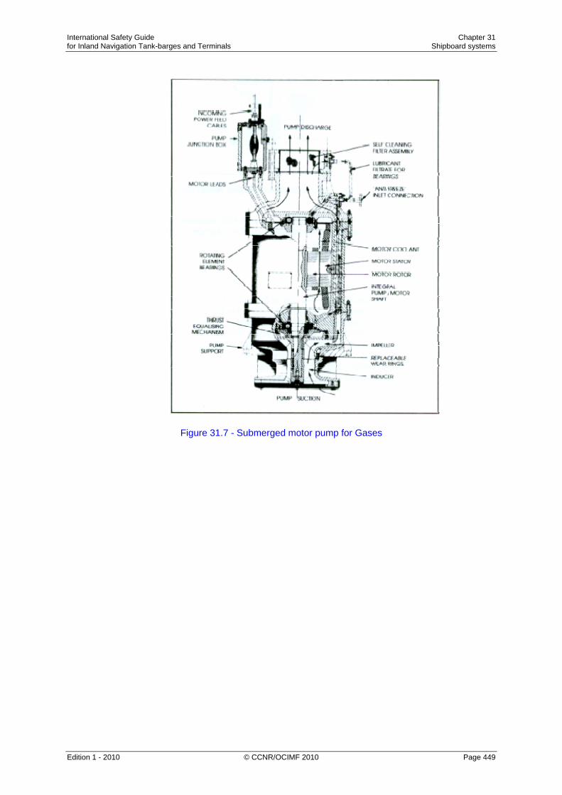
International Safety Guide Chapter 31 for Inland Navigation Tank-barges and Terminals Shipboard systems
Edition 1 - 2010 © CCNR/OCIMF 2010 Page 449
Figure 31.7 - Submerged motor pump for Gases

International Safety Guide Chapter 31 for Inland Navigation Tank-barges and Terminals Shipboard systems
Edition 1 - 2010 © CCNR/OCIMF 2010 Page 450
Figure 31.8 - Vertical booster pump
Figure 31.9 Horizontal booster pump

International Safety Guide Chapter 31 for Inland Navigation Tank-barges and Terminals Shipboard systems
Edition 1 - 2010 © CCNR/OCIMF 2010 Page 451
Ice prevention at cargo pumps The formation of ice or hydrates (see Section 27.9) may occur in tankers carrying refrigerated or semi-pressurised LPG. Furthermore, hydrates may be transferred from the terminal during loading operations. Hydrates from the shore can be removed by cargo filters in the terminal loading lines. Hydrate formations may enter cargo pumps, block lubricating passages, unbalance impellers and seize bearings. To prevent such damage it is common practice to inject a small quantity of freezing-point depressant into the cargo pump, especially submerged pumps, to facilitate de-icing. Because of the danger of methanol contamination to certain LPG cargoes, injection of this product should not normally be allowed without cargo receivers’ agreement. When deepwell pumps are not in operation, it is recommended that manual rotation of the shafts be carried out during cool-down and loading to prevent freezing of the impellers.
31.3 Cargo Heaters When discharging refrigerated cargoes into pressurised shore storage, it is usually necessary to heat the cargo so as to avoid low-temperature embrittlement of the shore tanks and pipelines. Cargo heaters are normally of the conventional horizontal shell and tube type exchanger. Most often, they are mounted in the open air on the tanker’s deck. Harbour water is commonly used as the heating medium and this passes inside the tubes with the cargo passing around the tubes. The heaters are typically designed to raise the temperature of fully refrigerated propane from -45°C to –5°C; however, it should be noted that the cargo flow rate at which this temperature rise may be achieved can be significantly reduced in cold water areas. Under such circumstances only very slow discharge rates may be possible and when water temperatures fall below 5°C it becomes increasingly difficult to use water as a heating medium.

International Safety Guide Chapter 31 for Inland Navigation Tank-barges and Terminals Shipboard systems
Edition 1 - 2010 © CCNR/OCIMF 2010 Page 452
Figure 31.10 - Cargo heater
Figure 31.10 shows a typical heater arrangement; note the requirement for temperature controls and alarms to avoid freezing. This is a very real risk which always has to be guarded against.
31.4 Cargo Vaporisers A means of producing cargo vapour from liquid is often required on gas carriers. For example, vapour may be needed to gas-up cargo tanks or to maintain cargo tank pressure during discharge. This latter need will be more obvious in the absence of a vapour return line from shore. Accordingly, a vaporiser is usually installed on board for these purposes. Cargo vaporisers may be either vertical or horizontal shell and tube heat exchangers. They are used with either steam or harbour water as the heating source.
31.5 Reliquefaction Plants and Boil-Off Control With the exception of fully pressurised gas carriers, means must be provided to control cargo vapour pressure in cargo tanks during cargo loading and on passage. In the case of LPG and chemical gas carriers, a reliquefaction plant is fitted for this purpose. This equipment is designed to perform the following essential functions: • To cool down the cargo tanks and associated pipelines before loading; • To reliquefy the cargo vapour generated by flash evaporation, liquid displacement and
boil-off during loading; and • To maintain cargo temperature and pressure within prescribed limits while at sea by
reliquefying the boil-off vapour.

International Safety Guide Chapter 31 for Inland Navigation Tank-barges and Terminals Shipboard systems
Edition 1 - 2010 © CCNR/OCIMF 2010 Page 453
There are two main types of reliquefaction plant and these are described in the following sections.
31.5.1 Indirect Cycles
Indirect cycle is descriptive of a system where an external refrigeration plant is employed to condense the cargo vapour without it being compressed. This cycle is relatively uncommon as its use is limited to a small numbers of cargoes. It requires, for efficiency, a very cold refrigerant and large surfaces for heat exchange.
This type of reliquefaction plant is, however, required by the Gas Codes when carrying any of the following cargoes • Chlorine. • Ethylene oxide. • Ethylene oxide — propylene oxide mix. • Propylene oxide.
Figure 31.10(a) - Examples of indirect cooling cycles Reference to Table 27.5 shows that with respect to propylene oxide it is unlikely, but dependent on ambient conditions, that refrigeration will be required on voyage. Two indirect cycle systems are shown diagrammatically in Figure 31.10(a).
31.5.2 Direct Cycles Direct cycle is descriptive of a system where the boil-off is compressed, condensed and returned to the tank. This is the most common system, but may not be employed for certain gases. There are three main types of direct cycle reliquefaction plant and these are described in the following sections.

International Safety Guide Chapter 31 for Inland Navigation Tank-barges and Terminals Shipboard systems
Edition 1 - 2010 © CCNR/OCIMF 2010 Page 454
Single-stage direct cycle The single-stage direct cycle system is particularly suited to the semi-pressurised carrier. A simplified diagram of single-compression reliquefaction is shown in Figures 31.11(a) and (b). This cycle is suitable where suction pressures are relatively high, as in the carriage of semi-pressurised products. Boil-off vapours from the cargo tank are drawn off by the compressor — (a) in the diagrams. Compression increases the pressure and temperature of the vapour — to (b) in the diagrams. The high temperature allows it to be condensed against sea water in the condenser — at (c) in the diagrams. The condensed liquid is then flashed back to the tank via a float controlled expansion valve — at (d) in the diagrams. The liquid/vapour mixture being returned the cargo tank may be either distributed by a spray rail at the top of the cargo tank or taken to the bottom of the tank to discourage re-vaporisation. The spray rail is normally used when the tank is empty and bottom discharge when the tank is full (see also Section 27.21 and Figure 27.18).
Figure 31.11(a) - Single-stage direct reliquefaction cycle

International Safety Guide Chapter 31 for Inland Navigation Tank-barges and Terminals Shipboard systems
Edition 1 - 2010 © CCNR/OCIMF 2010 Page 455
Figure 31.11(b) - Mollier diagram — single-stage direct reliquefaction cycle Two-stage direct cycle Although two-stage direct cycle equipment is relatively uncommon, it is used for those liquefied gas carriers handling a wide range of products. For grades such as butadiene and vinyl chloride its fitting is essential. A simplified diagram showing two-stage reliquefaction is given in Figures 31.12(a) and (b). The two-stage cycle with inter-stage cooling is used where suction pressures are low and, as a result, compression ratios high (assuming harbour water condensing) compared to the single-stage cycle. Two-stage compression (with inter-stage cooling) is necessary to limit the compressor discharge temperature which increases significantly with the higher compression ratio. This is particularly important for cargoes such as butadiene and vinyl chloride (see also Section 32.6).

International Safety Guide Chapter 31 for Inland Navigation Tank-barges and Terminals Shipboard systems
Edition 1 - 2010 © CCNR/OCIMF 2010 Page 456
Figure 31.12(a) - Two-stage direct reliquefaction cycle with inter-stage cooling
Figure 31.12(b) - Mollier diagram — two-stage direct reliquefaction cycle The vapour from the first stage discharge — (b) in the diagrams — is taken to an interstage cooler where its superheat is reduced — (c) in the diagrams. The cooling medium is cargo liquid flashed down to intercooler pressure from the harbour water-cooled condenser. The remaining parts of the cycle are similar to the single-stage cycle.
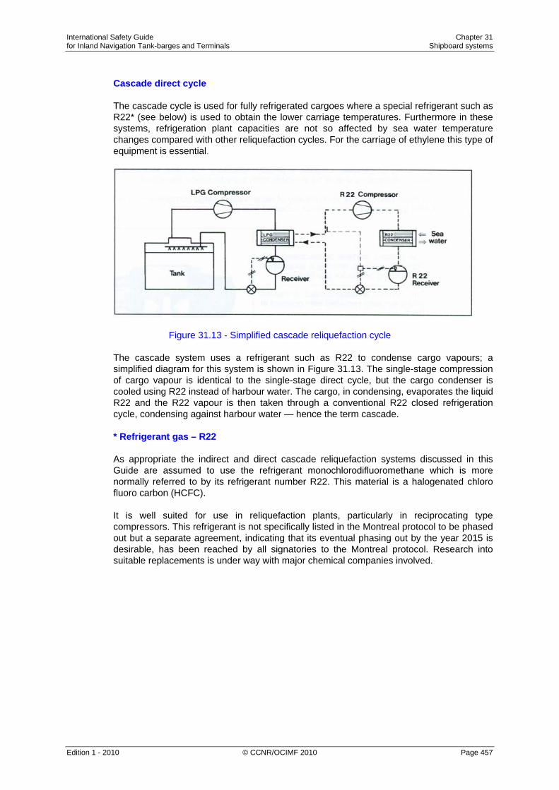
International Safety Guide Chapter 31 for Inland Navigation Tank-barges and Terminals Shipboard systems
Edition 1 - 2010 © CCNR/OCIMF 2010 Page 457
Cascade direct cycle The cascade cycle is used for fully refrigerated cargoes where a special refrigerant such as R22* (see below) is used to obtain the lower carriage temperatures. Furthermore in these systems, refrigeration plant capacities are not so affected by sea water temperature changes compared with other reliquefaction cycles. For the carriage of ethylene this type of equipment is essential.
Figure 31.13 - Simplified cascade reliquefaction cycle The cascade system uses a refrigerant such as R22 to condense cargo vapours; a simplified diagram for this system is shown in Figure 31.13. The single-stage compression of cargo vapour is identical to the single-stage direct cycle, but the cargo condenser is cooled using R22 instead of harbour water. The cargo, in condensing, evaporates the liquid R22 and the R22 vapour is then taken through a conventional R22 closed refrigeration cycle, condensing against harbour water — hence the term cascade. * Refrigerant gas – R22 As appropriate the indirect and direct cascade reliquefaction systems discussed in this Guide are assumed to use the refrigerant monochlorodifluoromethane which is more normally referred to by its refrigerant number R22. This material is a halogenated chloro fluoro carbon (HCFC). It is well suited for use in reliquefaction plants, particularly in reciprocating type compressors. This refrigerant is not specifically listed in the Montreal protocol to be phased out but a separate agreement, indicating that its eventual phasing out by the year 2015 is desirable, has been reached by all signatories to the Montreal protocol. Research into suitable replacements is under way with major chemical companies involved.

International Safety Guide Chapter 31 for Inland Navigation Tank-barges and Terminals Shipboard systems
Edition 1 - 2010 © CCNR/OCIMF 2010 Page 458
R22 has a very low toxicity; however, in the presence of a naked flame it breaks down into a toxic gas which has a very strong smell. As per the Montreal Protocol, R22 will eventually be phased out in the not too distant future. As per EU protocol 2037/2000, HCFC will be banned from January 2010.
31.6 Cargo Compressors and Associated Equipment The compressor is the heart of the reliquefaction plant. As far as LPG tankers are concerned there are two main types of compressor: these are the reciprocating type and the screw type.
31.6.1 Reciprocating Compressors Older compressors were sometimes not of the oil-free type. This attracted the problems discussed in Sections 27.10 and 32.6.1 because many liquefied gases can adversely affect the quality of the lubricating oil used in the machines. In using these older compressors, very careful control is required. In particular, sump heating systems are often fitted in order to evaporate any dissolved gases. In addition, the changing of lubricating oil between cargoes is usually necessary. Full data on the operation of these compressors should be available from manufacturers’ handbooks. For these reasons, the vast majority of reciprocating cargo compressors now found on board gas carriers are of the so-called oil-free type.

International Safety Guide Chapter 31 for Inland Navigation Tank-barges and Terminals Shipboard systems
Edition 1 - 2010 © CCNR/OCIMF 2010 Page 459
Figure 31.14 - Sulzer oil-free compressor In the Sulzer oil-free compressor shown in Figure 31.14, sealing between the piston and cylinder wall, and between the piston rod and gland, is achieved by the use of machined labyrinths. Consequently, no lubrication is needed for those spaces in the compressor swept by cargo vapours. The absence of any contact at the seals limits wear and lubricating oil consumption is minimal. The oil-free side of the compressor and the lubricated crank are separated by oil scraper rings mounted on the piston rod. The rod also carries a ring which prevents any residual oil film from creeping up the rod. The distance between the crank and gland is such that the oily part of the piston rod cannot enter the oil-free gland. Should any gas leak through the gland, it is returned to the suction side. The crankcase and separation space are kept under suction pressure. Where the crankshaft leaves the case, it is fitted with a shaft seal operating in oil.

International Safety Guide Chapter 31 for Inland Navigation Tank-barges and Terminals Shipboard systems
Edition 1 - 2010 © CCNR/OCIMF 2010 Page 460
Although the Sulzer compressor is oil-free in the compression chamber, it is common practice to change the lubricating oil with each change of cargo. This is to cover the question of compatibility of the lubricating oil grade with the next cargo (see Section 32.6.1). Capacity control of the compressor is achieved by lifting suction valves during the compression stroke. The plate lifters are normally hydraulically operated with the fluid pressure being provided by the lubricating oil pump. When the compressor is shut down, the cargo vapour in the crankcase can condense, giving rise to lubricating problems. To avoid this, provision must be made for crankcase heating when the compressor is idle. When the compressor is running, cooling must be provided for the crankcase, for the crossheads and for the guide bearings. Normally, a closed cycle glycol water system provides for the heating — when the compressor is shut down — and for cooling, when the compressor is running. Another common type of reciprocating oil-free compressor is shown in Figure 31.15. This machine is manufactured by Linde. Such a compressor has PTFE piston rings instead of the labyrinth piston in the Sulzer machines. Volumetric efficiencies tend to be higher with the PTFE ring design.
Figure 31.15 - Linde oil-free compressor

International Safety Guide Chapter 31 for Inland Navigation Tank-barges and Terminals Shipboard systems
Edition 1 - 2010 © CCNR/OCIMF 2010 Page 461
31.6.2 Screw Compressors
Screw compressors for use with liquefied gas cargoes can be either dry oil-free or oil-flooded machines. In the dry machines, the screw rotors do not make physical contact but are held in-mesh and driven by external gearing. Due to leakage through the clearances between the rotors, high speeds are necessary to maintain good efficiency (typically 12,000 rpm). Figure 31.16 is a diagram of a typical rotor set with the common combination of four and six lobes. The lobes inter-mesh and gas is compressed in the chambers numbered 1, 2, 3, in the diagram which are reduced in size as the rotors turn. The compressor casing carries the suction and discharge ports. The oil-flooded machine relies on oil injection into the rotors and this eliminates the need for timing gears. Drive power is transmitted from one rotor to the other by the injected oil. This also acts as a lubricant and coolant. Because the rotors are sealed with oil, gas leakage is much less and, therefore, oil-flooded machines can run at lower speeds (3,000 rpm). An oil separator on the discharge side of the machine removes oil from the compressed gas.
Figure 31.16 - Typical rotor for an oil-free screw compressor Capacity control of screw compressors can be achieved in a number of ways. The most common is the use of a sliding valve which effectively reduces the working length of the rotors. This is more efficient than suction throttling. Screw compressors consume more power than reciprocating compressors.

International Safety Guide Chapter 31 for Inland Navigation Tank-barges and Terminals Shipboard systems
Edition 1 - 2010 © CCNR/OCIMF 2010 Page 462
31.6.3 Compressor Suction Liquid Separator
It is necessary to protect cargo vapour compressors against the possibility of liquid being drawn in. Such a situation can seriously damage compressors since liquid is incompressible. It is normal practice, therefore, to install a liquid separator on the compressor suction line coming in from the cargo tanks. The purpose of this vessel is to reduce vapour velocity and, as a result, to allow any entrained liquid to be easily removed from the vapour stream. In case of over-filling, the separator is fitted with high-level sensors which set off an alarm and trip the compressor.
31.6.4 Purge Gas Condenser Many reliquefaction plants are fitted with a heat exchanger mounted above the cargo condenser. These units are of the shell and tube types. The purpose of this heat exchanger is to condense any cargo vapours which remain mixed with incondensable gases (such as nitrogen). These cargo vapours may have failed to condense in the main condenser. For example, commercial propane which may have 2 per cent ethane in the liquid will have perhaps 14 per cent ethane in the vapour; ethane being the more volatile component. On a semi-pressurised LPG carrier, the presence of ethane can cause difficulties in a conventional sea water-cooled condenser.
Figure 31.17 - Typical purge gas condenser system

International Safety Guide Chapter 31 for Inland Navigation Tank-barges and Terminals Shipboard systems
Edition 1 - 2010 © CCNR/OCIMF 2010 Page 463
Figure 31.17 shows a typical purge gas condenser system. The uncondensed gases in the main condenser are displaced into the shell of the purge condenser. Here they are subjected to the same pressure that exists in the main condenser but to a lower condensing temperature. This is equivalent to the outlet temperature from the expansion valve, since the whole or part of this liquid passes through the tube side of the purge condenser. This lower condensing temperature allows cargo vapours to be condensed and incondensible gases are purged from the top of the purge gas condenser by a pressure control system.
31.7 Inert Gas and Nitrogen Systems As covered in Section 27.7, gas carriers use various forms of inert gas and these are listed below: • Inert gas from combustion-type generators; • Nitrogen from shipboard production systems, and • Pure nitrogen taken from the shore (either by pipeline, road tanker or barge).
31.7.1 Nitrogen Production on Tankers The most common system utilised for the production of nitrogen on tankers is an air separation process. This system works by separating air into its component gases by passing compressed air over hollow fibre membranes. The membranes divide the air into two streams — one is essentially nitrogen and the other contains oxygen, carbon dioxide plus some trace gases. This system can produce nitrogen of about 95 up to 99.8 per cent purity. The capacity of these systems depends on the number of membrane modules fitted and is dependant on inlet air pressure, temperature and the required nitrogen purity. Figure 31.18 shows one such system.
Figure 31.18 - The membrane system for producing nitrogen

International Safety Guide Chapter 31 for Inland Navigation Tank-barges and Terminals Shipboard systems
Edition 1 - 2010 © CCNR/OCIMF 2010 Page 464
31.7.2 Pure Nitrogen from the Shore
The quality of inert gas produced by shipboard systems is usually inadequate for oxygen-critical cargoes — see strict in-tank oxygen requirements in Table 27.3(b). Bearing in mind the components in the inert gas, this may create restrictions on use if tanks have been previously gas-freed for inspection; and this is often necessary when a change in grades is involved. Under these circumstances, and prior to loading, it is normal for Masters to arrange for cargo tanks to be inerted with pure nitrogen, taken from the shore. This is usually delivered by pipeline, road tanker or barge. As deliveries are mostly in liquid form, where immediate inerting is required, a nitrogen vaporiser is needed.
31.8 Electrical Equipment in Gas Dangerous Spaces A common definition of area safety classification for electrical equipment is as follows: Zone 0: An area with a flammable mixture continuously present. Zone 1: An area where flammable mixtures are likely during normal operations. Zone 2: An area where flammable mixtures are unlikely during normal operations. Electrical installations on gas carriers are subject to the requirements of the classification society and the Gas Codes. Zones and spaces on tankers are classified as either gas-safe or gas-dangerous, depending on the risk of cargo vapour being present. For example, accommodation and machinery spaces are gas-safe, while compressor rooms, cargo tank areas and holds are gas-dangerous. In gas-dangerous spaces, only electrical equipment of an approved standard may be used; this applies to both fixed and portable electrical equipment. There are several types of electrical equipment certified as being safe for use on gas carriers and these are described in the following sections. Intrinsically safe equipment Intrinsically safe equipment can be defined as an electrical circuit in which a spark or thermal effect (under normal operation or specified fault conditions) is incapable of causing the ignition of a given explosive mixture. Limitation of such energy may be achieved by placing a barrier, as shown in Figure 31.19, in the electrical supply. This must be positioned in a safe area. Zener barriers are frequently used for this purpose and, in the circuit shown, the voltage is limited by the Zener diodes so that the maximum current flow to the hazardous area is restricted by the resistors. The uses of such intrinsically safe systems are normally limited to instrumentation and control circuitry in hazardous areas. Because of the very low energy levels to which they are restricted, intrinsically safe systems cannot be used in high-power circuits.

International Safety Guide Chapter 31 for Inland Navigation Tank-barges and Terminals Shipboard systems
Edition 1 - 2010 © CCNR/OCIMF 2010 Page 465
Figure 31.19 - Intrinsic safety using Zener barriers Flameproof equipment A flameproof enclosure is one which can withstand the pressure developed during an internal ignition of a flammable mixture. Furthermore, the design is such that any flames, occurring within the enclosure, are cooled to below ignition temperatures before reaching the surrounding atmosphere. Therefore, the gap through which hot gases are allowed to escape is critical and great care must be taken in assembly and maintenance of flameproof equipment to ensure that these gaps are well maintained. No bolts must be omitted or tightened incorrectly, while the gap must not be reduced by painting, corrosion or other obstructions. Pressurised or purged equipment The pressurisation or purging of equipment is a technique used to ensure that an enclosure remains gas-free. In the case of pressurisation, an over-pressure of about 0.5 bar, relative to the surrounding atmosphere, must be maintained. In the case of a purged enclosure, a continuous supply of purging gas must be provided to the enclosure. Air or inert gas can be used. Increased safety equipment The use of Increased Safety Equipment is appropriate for electrically powered light fittings and motors. This equipment has a greater than normal separation between electrical conductors and between electric terminals. Starters are designed to minimise both arcing at contactors and to limit the temperature of components. Increased safety motors, with flameproof enclosures, are frequently used on deck on gas carriers. Here they may be found driving deepwell pumps or booster pumps. In such cases they must be protected by a suitable weatherproof covering.

International Safety Guide Chapter 31 for Inland Navigation Tank-barges and Terminals Shipboard systems
Edition 1 - 2010 © CCNR/OCIMF 2010 Page 466
31.9 Instrumentation
Instrumentation is an important part of gas tanker equipment and is required for the measurement of cargo level, pressure and temperature. It is also used for gas detection. Instrumentation must be carefully selected and well maintained.
31.9.1 Liquid Level Instrumentation The applicable Gas Codes and classification society rules normally require every cargo tank to be fitted with at least one liquid level gauge. Specific types of gauging system are required for certain cargoes. Classification for gauging systems is as follows: • Indirect systems — these may be either weighing methods or flow meters. • Closed devices which do not penetrate the cargo tank — here ultrasonic devices or
radio isotope sources may be used. • Closed devices which penetrate the cargo tank — such as float gauges and radar type
gauges. Float gauges
Figure 31.20 - Float level gauge

International Safety Guide Chapter 31 for Inland Navigation Tank-barges and Terminals Shipboard systems
Edition 1 - 2010 © CCNR/OCIMF 2010 Page 467
The float gauge is widely used on all gas carriers. It consists of a float attached by a tape to an indicating device which can be arranged for local and remote readout. Figure 31.20 shows a typical float gauge installed in a tubular well. Alternatively guide wires may be fitted. Float gauges have gate valves for isolation so that the float can be serviced in a safe atmosphere. The float must be lifted from the liquid level when not in use; if left down, liquid sloshing especially in rough conditions, will damage the tape-tensioning device. Float gauges are normally placed in a tank sump or reach to a minimum distance to the tank bottom Radar gauges Another type of tank gauging equipment is that designed to operate on the principle of radar. Such equipment works at very high frequencies — approximately 11 gigahertz (11 x 109). Radar type liquid level gauges have now been specially developed for liquefied gases and their usage on gas tankers. The equipment provides measurements adequate to meet industry requirements. The above devices are classed as closed devices. This means that, when in use, no cargo liquids or vapours are released to the atmosphere during level measurement
31.9.2 Level Alarm and Automatic Shut-down Systems Every cargo tank should be fitted with an independent high level sensor giving audible and visual alarms. The float, capacitance or ultrasonic sensors may be used for this purpose. The high-high-level alarm — or other independent sensor — is required to automatically stop the flow of cargo to the tank. During cargo loading, there is a danger of generating a significant surge pressure if the valve stopping the flow closes too quickly against a high loading rate. (For further information on surge pressure see Sections 31.1.3 and 16.10).
31.9.3 Pressure and Temperature Monitoring The applicable Gas Codes should call for pressure monitoring throughout the cargo system. Appropriate positions include cargo tanks, pump and compressor discharge lines, liquid crossovers and vapour crossovers. In addition, pressure switches are fitted to various systems to protect personnel and equipment by operating alarms and shut-down systems. It is recommended that more than one thermometer be fitted to the cargo tanks to assist with monitoring to prevent undue thermal stresses. Tanker’s staff should be aware of the lowest temperatures to which the cargo tanks can be exposed and these values should be marked on the temperature gauges — especially those at the cargo manifold.

International Safety Guide Chapter 31 for Inland Navigation Tank-barges and Terminals Shipboard systems
Edition 1 - 2010 © CCNR/OCIMF 2010 Page 468

International Safety Guide Chapter 32 for Inland Navigation Tank-barges and Terminals Shipboard operations
Edition 1 - 2010 © CCNR/OCIMF 2010 Page 469
Chapter 32
SHIPBOARD OPERATIONS This Chapter takes the reader through a complete cycle of tanker loading and discharging operations, from a gas-free condition until a change of cargo is planned. When a gas carrier first comes alongside a berth to carry out cargo handling operations, it is essential that the preliminary procedures be properly completed. In particular, the questions given in the Safety Check-List should always be addressed. In line with Check-List questions, cargo handling plans should be developed and agreed jointly. Furthermore, written procedures should be established for controlling ship/shore cargo flow rates and for procedures covering general emergencies. It is in accordance with these plans that safe operations, as outlined in this Chapter, can be ensured. 32.1 Sequence of Operations
Assuming a gas carrier comes directly from a shipbuilder or drydock, the general sequence of cargo handling operations is as follows.

International Safety Guide Chapter 32 for Inland Navigation Tank-barges and Terminals Shipboard operations
Edition 1 - 2010 © CCNR/OCIMF 2010 Page 470
32.2 Tank Inspection, Drying and Inerting
32.2.1 Tank Inspection
Before any cargo operations are carried out, it is essential that cargo tanks are thoroughly inspected for cleanliness; that all loose objects are removed; and that all fittings are properly secured. In addition, any free water must be removed. Once this inspection has been completed, the cargo tank should be securely closed and air drying operations may start.
32.2.2 Drying Drying the cargo handling system in any refrigerated tanker is a necessary precursor to loading. This means that water vapour and free water must all be removed from the system. If this is not done, the residual moisture can cause problems with icing and hydrate formation within the cargo system. (The reasons are clear when it is appreciated that the quantity of water condensed when cooling down a 1000 m3 tank containing air at atmospheric pressure, 30°C and 100% humidity to 0°C would be 25 litres.) Whatever method is adopted for drying, care must be taken to achieve the correct dew point temperature - see Table 27.3(b). Malfunction of valves and pumps due to ice or hydrate formation can often result from an inadequately dried system. While the addition of antifreeze may be possible to allow freezing point depression at deep-well pump suctions, such a procedure must not substitute for thorough drying. (Antifreeze is only used on cargoes down to -48°C; propanol is used as a de-icer down to -108°C but below this temperature no de-icer is effective.) Tank atmosphere drying can be accomplished in several ways. These are described below. Drying using inert gas from the shore Drying may be carried out as part of the inerting procedure when taking inert gas from the shore (see Section 31.7) and this is now commonly done. This method has the advantage of providing the dual functions of lowering the moisture content in tank atmospheres to the required dew point and, at the same time, lowering the oxygen content. A disadvantage of this and the following method is that more inert gas is used than if it is simply a question of reducing the oxygen content to a particular value. For pressurised tanks the procedure should include a leak test with some overpressure. Drying using inert gas from tanker’s plant Drying can also be accomplished at the same time as the inerting operation when using the tanker’s inert gas generator but satisfactory water vapour removal is dependent on the specification of the inert gas system. Here, the generator must be of suitable capacity and the inert gas of suitable quality - but the necessary specifications are not always a design feature of this equipment. The tanker’s inert gas generator is sometimes provided with both a refrigerated dryer and an adsorption drier which, taken together, can reduce dew points at atmospheric pressure to -45°C or below. A shipboard nitrogen generator is much more efficient.

International Safety Guide Chapter 32 for Inland Navigation Tank-barges and Terminals Shipboard operations
Edition 1 - 2010 © CCNR/OCIMF 2010 Page 471
On board air-drying systems An alternative to drying with inert gas is by means of an air-drier fitted on board. The principle of operation is shown in Figure 32.1. In this method, air is drawn from the cargo tank by a compressor or provided by the on board inert gas blower (without combustion) and passed through a refrigerated drier. The drier is normally cooled by R22 refrigerant. Here the air is cooled and the water vapour is condensed out and drained off. The air leaving the drier is, therefore, saturated at a lower dew point. Further reduction of the dew point can be achieved by a silica gel after-drier fitted downstream. Thereafter, the air may be warmed back to ambient conditions by means of an air heater and returned to the cargo tank. This process is continued for all ship tanks (and pipelines) until the dew point of the in-tank atmosphere is appropriate to carriage conditions.
Figure 32.1 - Air Drying – operational cycle
32.2.3 Inerting - Before Loading Inerting cargo tanks, cargo machinery and pipelines is undertaken primarily to ensure a non-flammable condition during subsequent gassing-up with cargo. For this purpose, oxygen concentration must be reduced from 20.9 per cent to a maximum of five per cent by volume although lower values are often preferred - see Table 27.3(b). However, another reason for inerting is that for some of the more reactive chemical gases, such as vinyl chloride or butadiene, levels of oxygen as low as 0.1 per cent may be required to avoid a chemical reaction with the incoming vapour. Such low oxygen levels can usually only be achieved by nitrogen inerting provided from the shore (see Sections 27.7 and 31.7.2).
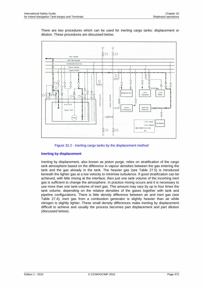
International Safety Guide Chapter 32 for Inland Navigation Tank-barges and Terminals Shipboard operations
Edition 1 - 2010 © CCNR/OCIMF 2010 Page 472
There are two procedures which can be used for inerting cargo tanks: displacement or dilution. These procedures are discussed below.
Figure 32.2 - Inerting cargo tanks by the displacement method
Inerting by displacement Inerting by displacement, also known as piston purge, relies on stratification of the cargo tank atmosphere based on the difference in vapour densities between the gas entering the tank and the gas already in the tank. The heavier gas (see Table 27.5) is introduced beneath the lighter gas at a low velocity to minimise turbulence. If good stratification can be achieved, with little mixing at the interface, then just one tank volume of the incoming inert gas is sufficient to change the atmosphere. In practice mixing occurs and it is necessary to use more than one tank-volume of inert gas. This amount may vary by up to four times the tank volume, depending on the relative densities of the gases together with tank and pipeline configurations. There is little density difference between air and inert gas (see Table 27.4); inert gas from a combustion generator is slightly heavier than air while nitrogen is slightly lighter. These small density differences make inerting by displacement difficult to achieve and usually the process becomes part displacement and part dilution (discussed below).

International Safety Guide Chapter 32 for Inland Navigation Tank-barges and Terminals Shipboard operations
Edition 1 - 2010 © CCNR/OCIMF 2010 Page 473
Inerting by displacement is an economical procedure as it uses the least amount of inert gas and takes the shortest time. However, it is only practical when mixing with the initial tank vapour can be limited. If the tank shape and the position of pipe entries are suitable for the displacement method, then results will be improved by inerting more than one tank at a time. This should be done with the tanks aligned in parallel. The sharing of the inert gas generator output between tanks reduces gas inlet speeds, so limiting vapour mixing at the interface. At the same time the total inert gas flow increases due to the lower overall flow resistance. Tanks being inerted in this way should be monitored to ensure equal sharing of the inert gas flow. Inerting by dilution When inerting a tank by the dilution method, the incoming inert gas mixes, through turbulence, with the gas already in the tank. The dilution method can be carried out in several different ways and these are described below: Dilution by repeated pressurisation In the case of Type ‘C’ tanks, inerting by dilution can be achieved through a process of repeated pressurisation. Each repetition brings the tank nearer and nearer to the oxygen concentration of the inert gas. Thus, for example, to bring the tank contents to a level of five per cent oxygen within a reasonable number of repetitions, inert gas quality of better than five per cent oxygen is required. It has been found that quicker results will be achieved by more numerous repetitions, each at low pressurisation, than by fewer repetitions at higher pressurisation. Continuous dilution Inerting by dilution can be carried out as a continuous process. Indeed, this is the only diluting process available for Type ‘A’ tanks which have very small over-pressure or vacuum capabilities. For a true dilution process, (as opposed to one aiming at displacement) it is relatively unimportant where the inert gas inlet or the tank efflux are located, provided that good mixing is achieved. Accordingly, it is usually found satisfactory to introduce the inert gas at high speed through the vapour connections and to discharge the gas mixture via the bottom loading lines. Where a number of tanks are to be inerted, it may be possible to achieve a reduction in the total volume of inert gas used, and the overall time taken, by inerting tanks one after the other in series. This procedure also inerts pipelines and equipment at the same time. (On some tankers, cargo and vapour pipeline arrangements may prevent more than two tanks being linked in series.) The extra flow resistance of a series arrangement will decrease the inert gas flow rate below that achievable when inerting tanks individually. As can be seen from the foregoing discussion, the optimum arrangement for inerting by dilution will differ from tanker to tanker and may be a matter of experience.

International Safety Guide Chapter 32 for Inland Navigation Tank-barges and Terminals Shipboard operations
Edition 1 - 2010 © CCNR/OCIMF 2010 Page 474
Inert gas - general considerations It can be seen from the preceding paragraphs that inert gas can be used in different ways to achieve inerted cargo tanks. No one method can be identified as the best since the choice will vary with tanker design and gas density differences. Generally, each individual tanker should establish its favoured procedure from experience. As already indicated, the displacement method of inerting is the best but its efficiency depends upon good stratification between the inert gas and the air or vapours to be expelled. Unless the inert gas entry arrangements and the gas density differences are appropriate to stratification, it may be better to opt for a dilution method. This requires fast and turbulent entry of the inert gas, upon which the efficiency of dilution depends. Whichever method is used, it is important to monitor the oxygen concentration in each tank from time to time, from suitable locations, using the vapour sampling connections provided. In this way, the progress of inerting can be assessed and, eventually, assurance can be given that the whole cargo system is adequately inerted. While the above discussion on inerting has centered on using an inert gas generator, the same principles apply to the use of nitrogen. The use of nitrogen may be required when preparing tanks for the carriage of chemical gases such as vinyl chloride, ethylene or butadiene. Because of the high cost of nitrogen, the chosen inerting method should be consistent with minimum nitrogen consumption. Inerting prior to loading ammonia Modern practice demands that ships’ tanks be inerted with nitrogen prior to loading ammonia. This is so, even though ammonia vapour is not readily ignited. Inert gas from a combustion-type generator must never be used when preparing tanks for ammonia. This is because ammonia reacts with the carbon dioxide in inert gas to produce carbamates. Accordingly, it is necessary for nitrogen to be taken from the shore as shipboard nitrogen generators are of small capacity. The need for inerting a ship’s tanks prior to loading ammonia is further underscored by a particular hazard associated with spray loading. Liquid ammonia should never be sprayed into a tank containing air as there is a risk of creating a static charge which could cause ignition. (Mixtures of ammonia in air also introduce an additional risk as they can accelerate stress corrosion cracking - see Section 27.5.)

International Safety Guide Chapter 32 for Inland Navigation Tank-barges and Terminals Shipboard operations
Edition 1 - 2010 © CCNR/OCIMF 2010 Page 475
32.3 Gassing-up
Gassing-up is absolutely necessary if a cooling plant is to be used since cooling plants cannot handle inert gases. Gassing-up operations are undertaken using cargo supplied from the shore. At certain terminals, facilities exist to allow the operation to be carried out alongside but these terminals are in a minority. This is because the venting of hydrocarbon vapours alongside a jetty may present a hazard and is, therefore, prohibited by most terminals and port authorities. Thus, well before a tanker arrives in port with tanks inerted, the following points must be considered by the Master: • Is venting allowed alongside? If so, what is permissible? • Is a vapour return facility to a flare available? • Is liquid or is vapour provided from the terminal for gassing-up? • Will only one tank be gassed-up and cooled down initially from the shore? • How much liquid must be taken on board to gas-up and cool-down the remaining
tanks? • Where can the full gassing-up operation be carried out? Before commencing gassing-up operations alongside, the terminal will normally sample tank atmospheres to check that the oxygen is less than five per cent for LPG cargoes (some terminals require as low as 0.5 per cent) or the much lower concentrations required for chemical gases such as vinyl chloride - see Table 27.3(b).
Figure 32.3(a) - Gassing-up cargo tanks using liquid from shore

International Safety Guide Chapter 32 for Inland Navigation Tank-barges and Terminals Shipboard operations
Edition 1 - 2010 © CCNR/OCIMF 2010 Page 476
Figure 32.3(b) - Gassing-up cargo tanks using vapour from shore Where no venting to atmosphere is permitted, a vapour return facility must be provided and used throughout the gassing-up operation. In this case, either the tanker’s cargo compressors or a jetty vapour blower can be used to handle the efflux. Some terminals, while prohibiting the venting of cargo vapours, permit the efflux to atmosphere of inert gas. Thus, if a displacement method of gassing-up is used - see Section 32.2.3 - the need for vapour return to shore may be postponed until cargo vapours are detected at the vent riser. This point may be considerably postponed if tanks are gassed-up one after the other in series. Where a terminal supplies a liquid for gassing-up, it should be loaded at a carefully controlled rate. It is then passed through the tanker’s vaporiser. Alternatively, the liquid may be allowed to vaporise in the ship’s tanks. If vapour is supplied, this can be introduced into the tank at the top or bottom depending on the vapour density (see Table 27.5). Figures 32.3(a) and 32.3(b) show typical gassing-up operations using liquid from shore and vapour from shore, respectively. When a tanker arrives alongside with tanks containing a cargo vapour which requires to be replaced with the vapour of a different grade, then the terminal will normally provide a vapour return line. The vapours taken to the shore will be flared until the desired vapour quality is achieved in the tanks. At this point cool-down can begin.

International Safety Guide Chapter 32 for Inland Navigation Tank-barges and Terminals Shipboard operations
Edition 1 - 2010 © CCNR/OCIMF 2010 Page 477
Recent developments have been made in LPG vapour recovery systems. Such systems are using the energy obtained from vapourising liquid nitrogen to reliquefy the cargo vapour returned from the tanker, either during gassing-up operations or during inerting operations, (see Section 32.9.3) thus avoiding any venting of hydrocarbon gases. The skid mounted unit would recieve liquid nitrogen from a truck, vapourise it for delivery to the tanker and at the same time reliquefy the return cargo vapour for storage and further usage.
32.4 Cool-Down Cool-down - refrigerated tanker Cooling down is necessary to avoid excessive tank pressures (due to flash evaporation) during bulk loading. Cool-down consists of spraying cargo liquid into a tank at a slow rate. The lower the cargo carriage temperature, the more important the cool down procedure becomes. Before loading a refrigerated cargo, the cargo tanks must be cooled down slowly in order to minimise thermal stresses. The rate at which a cargo tank can be cooled, without creating high thermal stress, depends on the design of the containment system and is typically 10°C per hour. Reference should always be made to the tanker’s operating manual to determine the allowable cool-down rate. The normal cool-down procedure takes the following form. Cargo liquid from shore (or from deck storage) is gradually introduced into the tanks either through spray lines, if fitted for this purpose, or via the cargo loading lines. The vapours produced by rapid evaporation may be taken ashore or handled in the tanker’s reliquefaction plant. Additional liquid is then introduced at a rate depending upon tank pressures and temperatures. If the vapour boil-off is being handled in the tanker’s reliquefaction plant, difficulties may be experienced with incondensibles, such as nitrogen, remaining from the inert gas. A close watch should be kept on compressor discharge temperatures and the incondensible gases should be vented from the top of the condenser as required (see Section 32.6).

International Safety Guide Chapter 32 for Inland Navigation Tank-barges and Terminals Shipboard operations
Edition 1 - 2010 © CCNR/OCIMF 2010 Page 478
Figure 32.4 - Cargo tank cool-down using liquid from shore: vapour returned to shore As the cargo containment system cools down, the thermal contraction of the tank combined with the drop in temperature around it tend to cause a pressure drop in the hold and interbarrier spaces. Normally, pressure control systems supplying air or inert gas will maintain these spaces at suitable pressures but a watch should be kept on appropriate instruments as the cool-down proceeds. Cool-down should continue until boil-off eases and liquid begins to form in the bottom of the cargo tanks. This can be seen from temperature sensors. At this stage, for fully refrigerated ammonia for example, the pool of liquid formed will be at approximately -34°C while the top of the tank may still be at -14°C. This gives a temperature difference of 20°C. The actual temperature difference depends on the size of the cargo tank and the spray nozzles positions. Difficulties that may occur during cool-down can result from inadequate gassing-up (too much inert gas remaining) or from inadequate drying. In this latter case, ice or hydrates may form and ice-up valves and pump shafts. In such cases, antifreeze can be added, provided the cargo is not put off specification, or the addition will not damage the electrical insulation of a submerged cargo pump. Throughout the cool-down, deepwell pump shafts should be turned frequently by hand to prevent the pumps from freezing up.

International Safety Guide Chapter 32 for Inland Navigation Tank-barges and Terminals Shipboard operations
Edition 1 - 2010 © CCNR/OCIMF 2010 Page 479
Once the cargo tanks have been cooled down, cargo pipelines and equipment should be cooled down. Figure 32.4 shows the pipeline arrangement for tank cool-down using liquid supplied from the shore. Cool-down - semi-pressurised tankers Most semi-pressurised ships have cargo tanks constructed of steels suitable for the minimum temperature of fully refrigerated cargoes. However, care must be taken to avoid subjecting the steel to lower temperatures. It is necessary to maintain a pressure within the cargo tank at least equal to the saturated vapour pressure corresponding to the minimum allowable steel temperature. This can be done by passing the liquid through the cargo vaporiser and introducing vapour into the tank with the cargo compressor. Alternatively, vapour can be provided from the shore.
32.5 Loading
32.5.1 Loading - Preliminary Procedures Before loading operations begin, the pre-operational ship/shore procedures must be thoroughly discussed and carried out. Appropriate information exchange is required and the relevant parts of the Safety Check List should be completed. Particular attention should be paid to: • The setting of cargo tank relief valves and high alarm pressures. • Remotely operated valves. • Reliquefaction equipment. • Gas detection systems. • Alarms and controls, and • The maximum loading rate. This should all be carried out taking into account restrictions in ship/shore systems. The terminal should provide the necessary information on the cargo, including inhibitor certificates where inhibited cargoes are loaded (see Section 27.8). Any other special precautions for specific cargoes should be made known to tanker personnel. This may include the lower compressor discharge temperatures required for some chemical gas cargoes (see Section 32.6). Where fitted, variable setting pressure relief valves, high tank pressure alarms and gas detection sample valves should be correctly set. The ballast system for gas carriers is totally independent of the cargo system. Deballasting can, therefore, take place simultaneously with loading, subject to local regulations. Tanker stability and stress are of primary importance during loading. Procedures for these matters are in accordance with normal tanker practice.
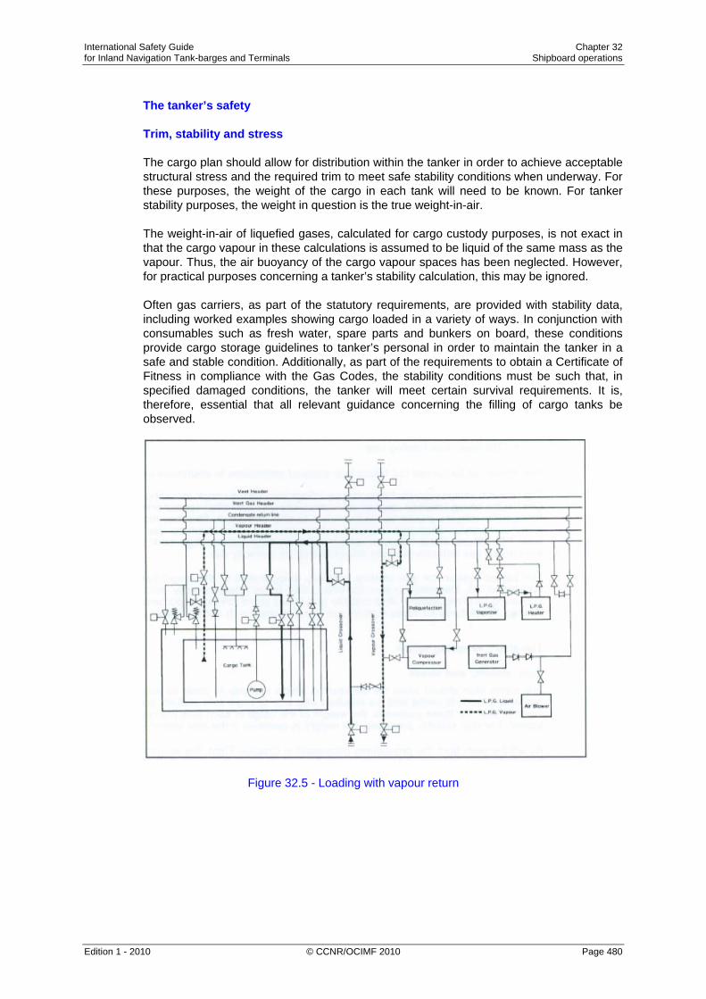
International Safety Guide Chapter 32 for Inland Navigation Tank-barges and Terminals Shipboard operations
Edition 1 - 2010 © CCNR/OCIMF 2010 Page 480
The tanker’s safety Trim, stability and stress The cargo plan should allow for distribution within the tanker in order to achieve acceptable structural stress and the required trim to meet safe stability conditions when underway. For these purposes, the weight of the cargo in each tank will need to be known. For tanker stability purposes, the weight in question is the true weight-in-air. The weight-in-air of liquefied gases, calculated for cargo custody purposes, is not exact in that the cargo vapour in these calculations is assumed to be liquid of the same mass as the vapour. Thus, the air buoyancy of the cargo vapour spaces has been neglected. However, for practical purposes concerning a tanker’s stability calculation, this may be ignored. Often gas carriers, as part of the statutory requirements, are provided with stability data, including worked examples showing cargo loaded in a variety of ways. In conjunction with consumables such as fresh water, spare parts and bunkers on board, these conditions provide cargo storage guidelines to tanker’s personal in order to maintain the tanker in a safe and stable condition. Additionally, as part of the requirements to obtain a Certificate of Fitness in compliance with the Gas Codes, the stability conditions must be such that, in specified damaged conditions, the tanker will meet certain survival requirements. It is, therefore, essential that all relevant guidance concerning the filling of cargo tanks be observed.
Figure 32.5 - Loading with vapour return

International Safety Guide Chapter 32 for Inland Navigation Tank-barges and Terminals Shipboard operations
Edition 1 - 2010 © CCNR/OCIMF 2010 Page 481
32.5.2 Control of Vapours During Loading
The control of cargo vapours during loading can be carried out by using: • A vapour return line to the shore coupled to a gas compressor. • The tanker’s reliquefaction plant for liquid return to the ship’s tanks, or • Both of the above. When loading with a vapour return line in use, the loading rate is independent of the capacity of the ship’s reliquefaction plant and is governed by: • The flow rate acceptable to the tanker and terminal, and • The capacity of the cargo vapour compressor. For fully refrigerated or semi-pressurised LPG tankers, a vapour return line is normally connected to the tanker’s vapour manifold but this is most often put in place for safety relief purposes. Normal loading practice on such tankers is to load through the liquid header, to draw off excess vapour via the vapour header, to operate the reliquefaction plant and to return the liquid to the ship’s tank via the condensate return line.
Figure 32.6 - Loading without vapour return

International Safety Guide Chapter 32 for Inland Navigation Tank-barges and Terminals Shipboard operations
Edition 1 - 2010 © CCNR/OCIMF 2010 Page 482
This operation controls cargo boil-off and ensures that tank pressure limits are not exceeded. The pipeline arrangement is shown in Figure 32.6. The introduction of a reliquefaction plant in the system can mean that loading rates are restricted by the capacity of the machinery. It is in this sense that the vapour return line acts as a safety device; should tank pressures become excessive, the tanker’s vapour manifold valve can be opened to relieve the situation. (For pressurised LPG carriers, the system should be similar to that described in this paragraph, and a vapour return should be fitted for safety relief purposes. However, a reliquefaction system is not fitted to such tankers and loading is normally achieved by shore pumps creating sufficient pressure to allow cargo tank vapour to continuously condense into the bulk liquid.) Where refrigerated storage is found in a terminal, the terminal’s reliquefaction capacity is usually greater than that provided on board tanker. As a result, where an LPG vapour return is used loading rates can be higher than those described in the previous paragraph. However, while advantageous, such systems for LPG are relatively rare. A problem experienced when using vapour returns in the LPG trades is that terminals can be concerned about the vapour quality to be returned to the shore. This is especially so at the early stages of loading. Terminal personnel can be concerned about residual nitrogen which acts as an incondensible during reliquefaction. They may also be concerned about contamination with vapours from previous cargoes. It is also difficult to account for the vapour returned to shore, especially if it is flared. This can lead to an overstatement of the Bill of Lading quantity, unless credit is given for the returned vapour. For these reasons it is unusual to find LPG terminals accepting return gas other than for safety reasons and then only to a flare.
32.5.3 Loading - Early Stages
Loading refrigerated tankers When liquefied gas is being loaded, it is necessary to consider the location, pressure, temperature and volume of the shore tanks as well as the terminal’s pumping procedures. Fully refrigerated tankers usually load from fully refrigerated storage where tanks typically operate at a pressure of approximately 60 millibars. This pressure will allow the cargo at the bottom of a full shore tank to sustain a temperature perhaps one degree Centrigrade warmer than its atmospheric boiling point. When this cargo is pumped to the jetty, the pumping energy required for transfer is dissipated in the liquid as heat, to which must be added the heat flow into the liquid through the pipelines. The cargo may, therefore, arrive on the tanker at an even warmer temperature. When loading without a vapour return line being used, the vapour which is displaced by the incoming liquid must be reliquefied on board. The power required for this, and to compensate for the pumping energy and the heat flux through the insulation, may leave little capacity for cooling the cargo during loading.

International Safety Guide Chapter 32 for Inland Navigation Tank-barges and Terminals Shipboard operations
Edition 1 - 2010 © CCNR/OCIMF 2010 Page 483
Therefore, as can be seen from the foregoing paragraphs, the early stages of loading can be critical, particularly where significant distances exist between the storage tank and jetty. The ship’s tank pressures must be regularly checked and on no account should relief valves be allowed to lift. Loading rates should be reduced, and if necessary stopped, when difficulties are experienced in maintaining acceptable tank pressures. In some ports in hot countries, where the terminal has long pipelines, this feature can be difficult to overcome. Under these circumstances, cargo stoppage would allow the pipeline contents once again to rise in temperature. Accordingly, in such ports, cargo flow should be maintained as long as it is safe to do so until cold product can be received on board at which time tank pressures will fall. A rise in ship’s tank pressure in the early stages of loading can also be controlled to some extent by loading limited quantities of liquid into the cargo tank via the top sprays, if fitted. This will help to condense some of the cargo vapours. Loading pressurised tankers Pressurised tankers normally arrive at a loading terminal having cargo tanks at atmospheric pressure. Firstly, the tanker requests vapours from the shore to purge any remaining nitrogen or contaminants from the tanks. This also allows the equalisation of tanker and shore pressures. Thereafter, the method used is to start loading in one tank at a high flow rate via the bottom line to avoid local low temperatures. In this case, as the liquid is allowed through, local flash-cooling can occur and it is important to ensure that at no time, tank or pipeline temperatures are allowed to fall below design limitations. Loading pressurised tankers from refrigerated storage The cargo tanks on fully pressurised tankers are made from carbon steel which is only suitable for a minimum temperature of between 0°C and –10°C. In contrast, LPG when stored in the fully refrigerated condition is maintained at the temperatures given in Table 27.5. Consequently, some refrigerated cargoes require considerable heating prior to loading on such tankers. Given that fully pressurised tankers may not have cargo heaters fitted on board, all heat input must be provided by pumping through heaters fitted on shore. Of course, on a pressurised tanker, having loaded a cargo at close to 0°C, the cargo may warm up further during the voyage in accordance with ambient conditions. The Gas Codes only allow cargo to be loaded to such a level that the tank filling limit will never be more than 98 per cent at the highest temperature reached during the voyage. This means that, during pre-loading discussions, tank topping-off levels must be established to allow sufficient room for liquid expansion into the vapour space while on voyage.

International Safety Guide Chapter 32 for Inland Navigation Tank-barges and Terminals Shipboard operations
Edition 1 - 2010 © CCNR/OCIMF 2010 Page 484
Loading semi-pressurised tankers from refrigerated storage The cargo tanks on semi-pressurised tankers are usually constructed of low temperature sheets able to accommodate fully refrigerated propane at temperatures of between -40°C and -50°C - or even for ethylene carriers at -104°C. Refrigerated cargoes can therefore be loaded directly to such tankers without heating. In addition, these tankers can usually maintain fully refrigerated temperatures on voyage and this is often done to gain more space so that a greater weight of cargo can be carried. The tank pressure must however always be maintained slightly above atmospheric. Temperatures of sub-cooled products under vacuum conditions can reach levels much lower than what is acceptable for the tank material. However, when discharge to pressurised storage is planned, this is conditional on the tanker having suitable equipment to warm the cargo. On semi-pressurised tankers, the cargo is occasionally allowed to warm up during the loaded voyage and in this case, a similar procedure to that described for fully pressurised tankers applies. Terminal pipeline system and operation Where a terminal can expect to load fully pressurised tankers not fitted with their own heaters, in-line equipment fitted to terminal pipeline systems is needed. This usually comprises the following: • Shore tank. • Cargo pump. • Booster pump. • Cargo heater. • Suitably sized loading arm. When considering a refrigerated terminal loading a fully pressurised tanker, given that loading temperatures on these tankers are limited to about 0°C, loadings can normally be managed by pumping through the refrigerated pipelines rated at 19 bar. Operation of the system takes the following form: Firstly, until back pressure starts to build up from the tanker, loading is carried out by pumping only through the cargo heater then, as the back pressure increases, the booster pump is also brought into operation. At the start of loading, the pressure in a ship’s tank should be at least 3 bar. This pressure will limit flashing-off and sub-cooling as the first liquid enters the tank. At this time, in-tank cargo temperatures should be carefully watched. Practical observation is also of value, with the sighting of ice formation on pipelines acting as a warning that temperatures on board the tanker are falling below safe levels. In such cases, loading must be stopped until temperatures increase and the problem is resolved. Small tanker problems at large berths A primary concern for the loading of small tankers is that refrigerated storage is most often designed for large ship/shore operations. At the jetty, this means that mooring plans must be properly adapted to accommodate the very different mooring patterns from small tankers and that loading arms or hoses are of a size suited to the operation.

International Safety Guide Chapter 32 for Inland Navigation Tank-barges and Terminals Shipboard operations
Edition 1 - 2010 © CCNR/OCIMF 2010 Page 485
Large loading arms can introduce difficulties on small tankers. If the berth is in an exposed area, a small tanker (being more sensitive, than a larger tanker, to the sea state) may roll and pitch at the berth. The loading arm has to keep pace with these fast movements and this is quite a different question from any slow changes (say tidal) which may be accommodated under normal design considerations. Here, the inertia of the loading arm has to be taken into account. At present, such dynamic forces are not considered in loading arm design and manufacturers leave this for terminal managers to address in operational procedures. In such cases, a possible solution is the use of cargo hose.
32.5.4 Bulk Loading Depending on the efficiency of the earlier gassing-up operation, significant quantities of incondensible gases may be present in tank atmospheres and, without vapour return to shore, these incondensibles will have to be vented via the tanker’s purge-gas condenser (where fitted) or, alternatively, from the top of the cargo condenser. Figure 31.17 shows a purge-gas condenser arrangement. Care must be taken when venting incondensibles to minimise venting of cargo vapours to the atmosphere. As the incondensibles are vented, the condenser pressure will drop and the vent valve should be throttled and eventually closed. A close watch should be kept on the ship’s cargo tank pressures, temperatures, liquid levels and interbarrier space pressures, throughout the loading operation. Monitoring of liquid levels may present difficulties when the reliquefaction plant is in operation. This is because the liquid in the tank is boiling heavily at these times and, as a result, vapour bubbles within the liquid increase its volume, thus giving false readings when using float-type ullage gauges. Accurate level monitoring can be achieved by suppressing boiling and this can be done by temporarily closing the vapour suction from the tank. Towards the end of loading, transfer rates should be reduced as previously agreed with shore personnel in order to accurately top-off tanks. On completion of loading, tanker’s pipelines should be drained back to the cargo tanks. Remaining liquid residue can be cleared by blowing ashore with vapour, using the tanker’s compressor. Alternatively, this residue may be cleared by nitrogen injected into the loading arm to blow the liquid into the ship’s tanks. Once liquid has been cleared and pipelines have been depressurised, manifold valves should be closed and the hose or loading arm disconnected from the manifold flange. In many ports it is a requirement, before disconnection takes place, for the hard arm, hose and pipelines at the manifold to be purged free from flammable vapour. The relief valves of some tankers have dual settings to allow higher tank pressures during the loading operation. If relief valve settings are altered by changing the pilot spring, then the procedure must be properly documented and logged and the current MARVS must be prominently displayed. Relief valves must be reset before the tanker departs. When relief valve pressure settings are changed, high pressure alarms have to be readjusted accordingly.
International Safety Guide Chapter 32 for Inland Navigation Tank-barges and Terminals Shipboard operations
Edition 1 - 2010 © CCNR/OCIMF 2010 Page 486
32.5.5 Cargo Tank Filling Limits
The goal of filling limits is: • Economical and safe use of tank capacity. • To avoid overfilling of tanks, in this respect more than 98 % is seen as overfilling. • To avoid tank failure in the exceptional case of fire conditions.
The use of different settings of safety valves should be avoided as far as practical or only with additional safety procedures. Tanks should be provided with double safety valves with a manual valve under each safety valve. Both safety valves should be in the open position under normal conditions. There should be means to avoid the possibility to close both valves at the same time. Chapter 15 (amended 1994) of the IGC code gives guidance for “best practice” on how to determine the maximum filling limits. This includes the required technical lay-out and procedures. Short description of the IGC Code regulation: The large thermal coefficient of expansion of liquefied gas necessitates requirements for maximum allowable filling limits for cargo tanks in order to avoid over filling of the cargo tanks. Filling limits differ and depend on: product, transport conditions and regions. For particular regions there may be prescribed filling conditions which must be adhered to. The latest developments for determining filling limits are laid down in the amended Chapter 15 of the IGC code. For the purpose of this Chapter the following definitions apply: 1. Reference Temperature means the highest temperature which may be reached upon
termination of loading, during transport, or during unloading, under the ambient design temperature conditions.
2. Filling limit (FL) expressed in % means the maximum allowable liquid volume in a cargo tank relative to the tank volume when the liquid cargo has reached the reference temperature.
3. Loading limit (LL) expressed in % means the maximum allowable liquid volume relative to the tank volume to which a tank may be loaded in order to avoid the liquid volume exceeding the allowable filling limit in service.
The administration may allow a higher filling limit than the limit of FL = 98% specified at the reference temperature, taking into account the shape of the tank, arrangements of pressure relief valves, accuracy of level and temperature gauging and the difference between the loading temperature and the reference temperature, provided the conditions specified in the IGC Code, Chapter 8.2.17 are maintained.

International Safety Guide Chapter 32 for Inland Navigation Tank-barges and Terminals Shipboard operations
Edition 1 - 2010 © CCNR/OCIMF 2010 Page 487
The maximum loading limit (LL) to which a cargo tank may be loaded is determined by the following formula:
ρR LL = FL —— ρL where: FL = filling limit as specified ρR = relative density of the cargo at the reference temperature. ρL = relative density of the cargo at the loading temperature and pressure. Information to be provided to the Master The maximum allowable tank loading (LL) for each tank should be indicated for each product which may be carried, for each loading temperature which may be applied and for the applicable maximum reference temperature, on a list to be provided by the administration. The pressure at which the pressure relief valves have been set shoud also be stated on the list. A copy of the list should be permanently kept on board by the Master. The use of the above formula requires a special layout of the venting system which is laid down in Chapter 8 of the Gas Code. There are good safety reasons for minimising cargo shut-out. The concept is very simple. The fuller the tank, the longer the tank structure will be able to withstand fire conditions. The tank contents, when exposed to a fire, will boil at a constant temperature until the bulk of the liquid has been vented through the relief valve system. After this, the upper regions of the tank become exceedingly hot and eventually fail. However, the greater the mass of liquid inside the tank, the longer the tank can withstand unacceptable external temperatures. General Local requirements may have different approaches to the prescription of maximum filling limits but, in any event, the temperature influences on liquefied gases should not be ignored.

International Safety Guide Chapter 32 for Inland Navigation Tank-barges and Terminals Shipboard operations
Edition 1 - 2010 © CCNR/OCIMF 2010 Page 488
Example Case 1 (amended Gas Code regulation) A fully pressurised ship loading propane at 5°C. ρR LL = FL —— ρL Reference temperature as calculated under amended Gas Code 20°C Density of liquid propane at 20°C = 500 kg/m3 Loading temperature 5°C Density of liquid propane at 5°C = 522 kg/m3 500 LL = 98 x —— = 93.9% 522 Thus, the tank can be loaded to 93.9% of tank volume. Case 2 (amended Gas Code regulation) A fully-pressurised tanker loading propane at -10°C. Reference temperature as calculated under amended Gas Code +15°C Density of liquid propane at 15°C = 508 kg/m3 Loading temperature = -10°C Density of liquid propane at -10°C = 542kg/m3 508 LL = 98 x —— = 91.9% 542 Thus, the tank can be loaded to 91.9% of tank volume.
32.6 The Loaded Voyage Cargo temperature control For all refrigerated and semi-pressurised gas carriers, it is necessary to maintain strict control of cargo temperature and pressure throughout the loaded voyage. This is achieved by reliquefying cargo boil-off and returning it to the tanks (see also Sections 32.5 and 31.5). During these operations, incondensibles must be vented as necessary to minimise compressor discharge pressures and temperatures. Frequently, there are occasions when it is required to reduce the temperature of an LPG cargo on voyage. This is necessary so that the tanker can arrive at the discharge port with cargo temperatures below that of the shore tanks, thus minimising the amount of flash gas. Depending on the cargo and reliquefaction plant capacity, it can often take several days to cool the cargo by one or two degrees centigrade, but this may be sufficient. The need for this will often depend on the contractual terms in the charter party.

International Safety Guide Chapter 32 for Inland Navigation Tank-barges and Terminals Shipboard operations
Edition 1 - 2010 © CCNR/OCIMF 2010 Page 489
In this respect, poor weather conditions can sometimes present problems. Although most reliquefaction plants have a suction knock-out drum to remove liquid, there is a risk, in gale conditions, that entrained liquid can be carried over into the compressor. For this reason, it is preferable not to run compressors when the tanker is rolling heavily, if there is risk of damage. In calm weather conditions, if the condensate returns are passed through the top sprays, because of the small vapour space and poor circulation in the tank, it is possible that a cold layer can form on the liquid surface. This enables the compressors to reduce the vapour pressure after only a few hours running, when in fact the bulk of the liquid has not been cooled at all. To achieve proper cooling of the bulk liquid, the reliquefaction plant should be run on each tank separately and the condensate should be returned through a bottom connection to ensure proper circulation of the tank contents. After the cargo has been cooled, reliquefaction capacity can be reduced to a level sufficient to balance the heat flow through the tank insulation. Figure 32.7 shows the arrangement for cooling down cargoes on a loaded voyage. If the reliquefaction plant is being run on more than one tank simultaneously, it is important to ensure that the condensate returns are carefully controlled in order to avoid the overfilling of any one tank.
Figure 32.7 - Cargo refrigeration at sea
International Safety Guide Chapter 32 for Inland Navigation Tank-barges and Terminals Shipboard operations
Edition 1 - 2010 © CCNR/OCIMF 2010 Page 490
Prevention of polymerisation Where butadiene cargoes are being carried, the compressor discharge temperature must not exceed 60°C and the appropriate high discharge temperature switch must be selected. Similarly, in the case of vinyl chloride, compressor discharge temperatures should be limited to 90°C to prevent polymerisation (see also Section 27.8). Condition inspections Throughout the loaded voyage, regular checks should be made to ensure there are no defects in cargo equipment and no leaks in nitrogen or air supply lines. Such inspections must comply with all relevant safety procedures for entry into enclosed spaces and due regard must be given to hazardous atmospheres in adjacent spaces.
32.6.1 Operation of the Reliquefaction Plant As already mentioned in Section 31.5, the reliquefaction plant is used during cargo loading to handle the vapours formed by evaporation and displacement. At this time, it is likely that the maximum compressor capacity will be required. On the loaded voyage, and depending on cargo temperature, ambient temperature, and the design of tank insulation, the plant may be operated continuously or intermittently. If it is necessary to reduce the temperature of the cargo before reaching the discharge port, for example, to comply with the receiving terminal requirements or charter party stipulations, the plant will again be operating continuously. Before starting the reliquefaction plant, it is necessary to ensure that oil levels in the compressors are correct and that the glycol/water cooling system is ready for operation (see Section 31.6.1). This will require a check to make sure the header tank is full and that the cooling fluid is circulating. The lubricating oil in compressors must be compatible with the cargo being handled and must be changed if necessary. (When changing from butane/propane mixtures to other grades, it will be necessary to change the oil.) Before starting a cargo compressor, the condenser cooling system must be operating with harbour water circulating or the R22 system running. Compressors should always be started and stopped in accordance with the manufacturer’s instructions. Compressor discharge valves should be opened and suction valves opened slowly to minimise damage from liquid carry-over (see Section 31.6.3). The cooling water outlet temperature should be adjusted in accordance with the manufacturer’s instructions. The following details should be checked regularly: • Suction, inter-stage (see Section 31.5) and discharge pressures. • Lubricating oil pressures. • Gas temperatures on the suction and delivery side of compressor (high discharge
temperature switches protect the compressor). Here, inspection of the appropriate Mollier diagram will assist in gaining maximum benefit from the compressor by ensuring that it operates along the appropriate line of constant entropy (see Section 27.21).
• Current drawn by electric motor. • Oil leakage from shaft seal, and • Cooling water temperature.

International Safety Guide Chapter 32 for Inland Navigation Tank-barges and Terminals Shipboard operations
Edition 1 - 2010 © CCNR/OCIMF 2010 Page 491
Stopping the cargo compressor should always be carried out in accordance with the manufacturer’s instructions. Generally, the first action is to stop the compressor. This is followed by closure of the suction and discharge valves. The glycol/water system (see Section 31.6.1) is left running to provide crankcase heating or, alternatively, the lubricating oil heater should be left switched on.
32.7 Discharging
When a tanker arrives at the discharge terminal, cargo tank pressures and temperatures should be in accordance with terminal requirements. This will help maximum discharge rates to be achieved. Before the discharge operation begins, the pre-operational ship/shore procedures should be carried out along similar lines to the loading operation previously outlined. The method of discharging the tanker will depend on the type of tanker, cargo specification and terminal storage. Three basic methods may be used: • Discharge by pressurising the vapour space. • Discharge with or without booster pumps. • Discharge via booster pump and cargo heater.
These methods are discussed in 32.7.1, 32.7.2 and 32.7.3 below.
32.7.1 Discharge by Pressurising the Vapour Space
Discharge by pressure using either a shore vapour supply or a vaporiser and compressor on board is only possible where Type ‘C’ tanks are fitted. It is an inefficient and slow method of discharge and is restricted to small tankers of this type. Using this system, the pressure above the liquid is increased and the liquid is transferred to the terminal. An alternative method is to pressurise the cargo into a small deck tank from which it is pumped to the shore.
32.7.2 Discharge by Pumps Starting cargo pumps A centrifugal pump should always be started against a closed, or partially open, valve in order to minimise the starting load. Thereafter, the discharge valve should be gradually opened until the pump load is within safe design parameters and liquid is being transferred ashore. As the discharge proceeds, the liquid level in the cargo tanks should be monitored. Discharge and ballasting operations should be carefully controlled, bearing in mind tanker stability and hull stress.
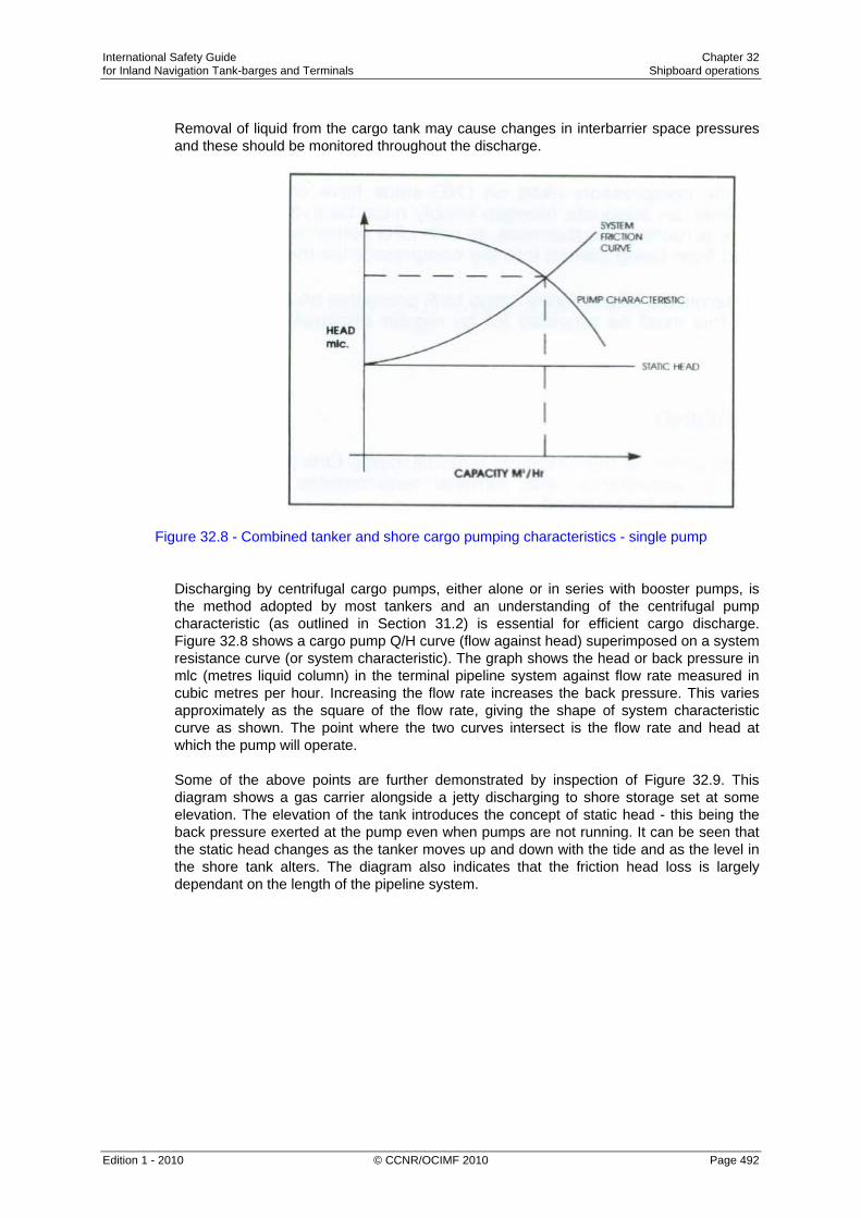
International Safety Guide Chapter 32 for Inland Navigation Tank-barges and Terminals Shipboard operations
Edition 1 - 2010 © CCNR/OCIMF 2010 Page 492
Removal of liquid from the cargo tank may cause changes in interbarrier space pressures and these should be monitored throughout the discharge.
Figure 32.8 - Combined tanker and shore cargo pumping characteristics - single pump Discharging by centrifugal cargo pumps, either alone or in series with booster pumps, is the method adopted by most tankers and an understanding of the centrifugal pump characteristic (as outlined in Section 31.2) is essential for efficient cargo discharge. Figure 32.8 shows a cargo pump Q/H curve (flow against head) superimposed on a system resistance curve (or system characteristic). The graph shows the head or back pressure in mlc (metres liquid column) in the terminal pipeline system against flow rate measured in cubic metres per hour. Increasing the flow rate increases the back pressure. This varies approximately as the square of the flow rate, giving the shape of system characteristic curve as shown. The point where the two curves intersect is the flow rate and head at which the pump will operate. Some of the above points are further demonstrated by inspection of Figure 32.9. This diagram shows a gas carrier alongside a jetty discharging to shore storage set at some elevation. The elevation of the tank introduces the concept of static head - this being the back pressure exerted at the pump even when pumps are not running. It can be seen that the static head changes as the tanker moves up and down with the tide and as the level in the shore tank alters. The diagram also indicates that the friction head loss is largely dependant on the length of the pipeline system.

International Safety Guide Chapter 32 for Inland Navigation Tank-barges and Terminals Shipboard operations
Edition 1 - 2010 © CCNR/OCIMF 2010 Page 493
Figure 32.9 - Illustrations of static head and friction head
Consider now the situation where pumps are run in parallel, as would be the normal case for a gas carrier discharge. Figure 32.10 shows the pump characteristics using one pump and when using two, three or four similar pumps in parallel. (This family of curves is derived from the principles discussed in Section 31.2). Superimposed on the pump characteristics are a number of system characteristics labelled ‘A’, ‘B’ and ‘C’. System characteristic ‘A’ indicates a small diameter shore pipeline, ‘B’ a larger diameter pipeline and ‘C’ a very large diameter pipeline with shore tanks situated nearby. The latter provides the least resistance to cargo flow. The actual system characteristic applicable at any terminal should be known to shore personnel and they should have such curves available. In preparing such graphs, personnel should note, as mentioned above, that the system characteristic can vary with the size of the chosen pipeline and with variation in the pipe-lengths from the jetty when alternative shore tanks are used. If a range of pipelines and tanks are available at any one terminal, then, it may be appropriate for terminal personnel to have a number of system characteristics, already pre-calculated and available, for use during pre-transfer discussions.

International Safety Guide Chapter 32 for Inland Navigation Tank-barges and Terminals Shipboard operations
Edition 1 - 2010 © CCNR/OCIMF 2010 Page 494
In any case, during the pre-transfer discussions (see Section 22.4), such matters should be covered and the optimum transfer rate should be agreed.
Figure 32.10 - Combined tanker and shore cargo pumping characteristics - parallel pumps
To clarify some of these issues, two of the system characteristics, as shown in Figure 32.10, are covered in detail below. If a tanker, having the pumping characteristics as shown in Figure 32.10 (numbered 1, 2, 3, and 4), is discharging to a terminal presenting only minor restrictions to flow, then the shore system characteristic may be equivalent to ‘C’. The operating point of the ship/shore system moves from points C1 through to C4 as the number of cargo pumps in operation is increased from one to four. Under such conditions, the total flow achieved (when using four pumps) is only marginally less than the total theoretical flow (assuming no resistance). With such a shore pipeline system, it is therefore probable that all four pumps (and maybe more) can be run to good effect. In the case of system characteristic ‘A’, where flow restrictions are high, it can be seen how little extra flow is achieved by running more than two pumps. By running three pumps the operating point moves from A2 to A3, achieving some extra throughput. By running four pumps the operating point moves from A3 to A4, achieving an increased flow of virtually zero. In such cases, much of the energy created in the additional pumps is imparted to the cargo. This is converted to heat in the liquid and results in an increase in cargo temperature. This increases flash-gas boil-off as the liquid discharges into shore storage and this excess must be handled by the shore compressors. If the shore compressors are unable to handle the additional flash-gas, the terminal will require a reduction in flow rate to avoid lifting the shore relief valves. Therefore, the net effect, in restricted circumstances, of running an unnecessary number of pumps can be to decrease rather than to increase the overall discharge rate.

International Safety Guide Chapter 32 for Inland Navigation Tank-barges and Terminals Shipboard operations
Edition 1 - 2010 © CCNR/OCIMF 2010 Page 495
Observing pressure gauges at the manifold will give a good indication if it is worthwhile running, say, four pumps or six pumps. The discharge rate should not be reduced by throttling valves at the tanker’s cargo manifold if the shore cannot accept the discharge rate. Throttling in this manner further heats up the cargo. However, those gas carriers with only limited recirculation control may have to use manifold valves to throttle pumps.
Figure 32.11 - Discharge without vapour return
Figure 32.12 - Discharge with vapour return
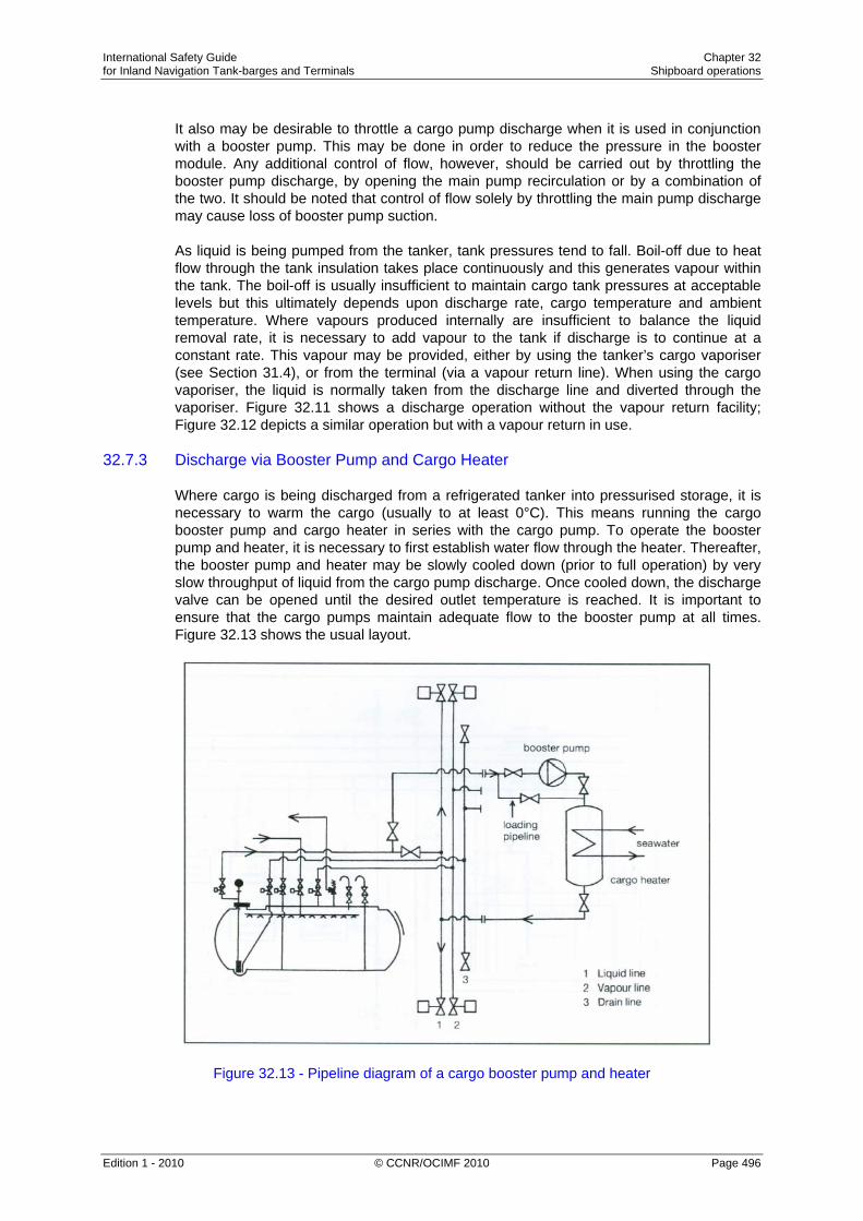
International Safety Guide Chapter 32 for Inland Navigation Tank-barges and Terminals Shipboard operations
Edition 1 - 2010 © CCNR/OCIMF 2010 Page 496
It also may be desirable to throttle a cargo pump discharge when it is used in conjunction with a booster pump. This may be done in order to reduce the pressure in the booster module. Any additional control of flow, however, should be carried out by throttling the booster pump discharge, by opening the main pump recirculation or by a combination of the two. It should be noted that control of flow solely by throttling the main pump discharge may cause loss of booster pump suction. As liquid is being pumped from the tanker, tank pressures tend to fall. Boil-off due to heat flow through the tank insulation takes place continuously and this generates vapour within the tank. The boil-off is usually insufficient to maintain cargo tank pressures at acceptable levels but this ultimately depends upon discharge rate, cargo temperature and ambient temperature. Where vapours produced internally are insufficient to balance the liquid removal rate, it is necessary to add vapour to the tank if discharge is to continue at a constant rate. This vapour may be provided, either by using the tanker’s cargo vaporiser (see Section 31.4), or from the terminal (via a vapour return line). When using the cargo vaporiser, the liquid is normally taken from the discharge line and diverted through the vaporiser. Figure 32.11 shows a discharge operation without the vapour return facility; Figure 32.12 depicts a similar operation but with a vapour return in use.
32.7.3 Discharge via Booster Pump and Cargo Heater Where cargo is being discharged from a refrigerated tanker into pressurised storage, it is necessary to warm the cargo (usually to at least 0°C). This means running the cargo booster pump and cargo heater in series with the cargo pump. To operate the booster pump and heater, it is necessary to first establish water flow through the heater. Thereafter, the booster pump and heater may be slowly cooled down (prior to full operation) by very slow throughput of liquid from the cargo pump discharge. Once cooled down, the discharge valve can be opened until the desired outlet temperature is reached. It is important to ensure that the cargo pumps maintain adequate flow to the booster pump at all times. Figure 32.13 shows the usual layout.
Figure 32.13 - Pipeline diagram of a cargo booster pump and heater

International Safety Guide Chapter 32 for Inland Navigation Tank-barges and Terminals Shipboard operations
Edition 1 - 2010 © CCNR/OCIMF 2010 Page 497
Heating cargo during discharge always entails a risk of freezing the circulating water in the heater. In addition to checking the cargo outlet temperature and the booster pump suction during operation, attention should also be paid to the water inlet and outlet temperatures and pressures. The water outlet temperature must not be allowed to fall below the manufacturer’s recommended limit. A low temperature switch should stop cargo flow through the heater in case of low water discharge temperature. As will be noted, this method of cargo heating depends on a suitable water temperature. In cold water areas, the efficiency of the system can be seriously affected and slow discharge rates can result and if water temperatures are below 5°C the risk of freezing becomes much greater. To cover such possibilities, sometimes thermal oil heaters are fitted to tankers.
32.7.4 Draining Tanks and Pipelines It has already been noted in Section 31.2 and illustrated in Figure 31.3 that in order to avoid cavitation of a centrifugal pump, the pressure of the liquid at the pump suction needs to exceed the saturated vapour pressure (SVP) by an amount termed the minimum Net Positive Suction Head (NPSH). The required minimum NPSH, expressed as an equivalent head of liquid above the pump suction, may vary from one metre (at maximum pump capacity) to 200 millimetres (at reduced flow). If the vapour space pressure can be increased above the SVP by the supply of extra vapour from the shipboard vaporiser, the onset of cavitation, as the liquid level approaches the bottom of the tank, can be delayed. Such augmentation of vapour space pressure is usual practice on fully pressurised and semi-pressurised tankers and may also be carefully applied to fully refrigerated cargoes, particularly where maximum cargo out-turn is required in preparation for gas freeing. Whether this extra vapour pressurisation is used or not, there will be a liquid level at which the pump becomes erratic. Gradual reduction of the flow rate at this point, by careful throttling of the discharge valve, reduces the NPSH requirement and permits continued discharge to a lower level. It should be remembered, however, that a pump discharge valve should not be used for flow control if the pump is operating with a booster pump since the booster pump might cavitate, resulting in damage (see Section 32.7.2). On completion of discharge, liquid cargo must be drained from all deck lines and cargo hoses or hard arms. Such draining can be done from tanker to shore using a cargo compressor. Alternatively, it may be carried out from shore to tanker, normally by blowing the liquid into the ship’s tanks using nitrogen injected at the base or apex of the hard arm. Only after depressurising all deck lines and purging with nitrogen should the ship/shore connection be broken.

International Safety Guide Chapter 32 for Inland Navigation Tank-barges and Terminals Shipboard operations
Edition 1 - 2010 © CCNR/OCIMF 2010 Page 498
32.8 The Ballast Voyage
It is frequent practice in some refrigerated trades to retain a small quantity of cargo on board after discharge and the amount retained is known as the heel. This product is used to maintain the tanks at reduced temperature during the ballast voyage but this procedure only applies when the same grade of cargo is to be loaded at the next loading terminal. In general, the quantity retained on board as a heel depends on: • Commercial agreements. • The type of gas carrier. • The duration of the ballast voyage. • The next loading terminal’s requirements, and • The next cargo grade. With LPG cargoes, the small amount of liquid remaining after discharge should be sufficient to provide the necessary cooling effect during the ballast voyage. This is carried out by intermittent use of the reliquefaction plant, returning the condensate to the tanks to ensure arrival at the loading port with tanks and product suitably cooled. If the tanker is proceeding to a loading terminal to load an incompatible product, none of the previous cargo should be retained on board. This avoids contamination of the following cargo and allows the maximum quantity of the new cargo to be loaded (see Section 32.9).
32.9 Changing Cargo (and Preparation for Drydock) Of all the operations undertaken by a gas carrier, the preparation for a change of cargo is the most time consuming. If the next cargo is not compatible with the previous cargo, it is often necessary for the tanks to be gas-freed to allow a visual inspection - see Table 27.3(b). This is commonly the case when loading chemical gases such as vinyl chloride, ethylene or butadiene. When a tanker receives voyage orders, a careful check must be made on the compatibility of the next cargo. (It is also necessary to check compatibilities and the tanker’s natural ability to segregate, if more than one cargo grade is to be carried. On such occasions, special attention must be given to the tanker’s reliquefaction system.) There may also be a need, when changing cargoes, to replace the lubricating oil in compressors for certain cargoes - this is discussed in Sections 32.6.1 and 31.6.1. Tables 27.3(a) and 27.3(b) provide a guide to the compatibility of gases. The tables also cover cargo compatibility with respect to the construction materials commonly used in cargo handling systems. In order to obtain a gas-free condition, the full process is as shown below. However, depending on the grade switch, it may not be necessary to include all these steps: • First, make the tank liquid free. • Then, warm the tank with hot cargo vapours (if necessary). • Next, inert the tank, and • Finally, ventilate with air.

International Safety Guide Chapter 32 for Inland Navigation Tank-barges and Terminals Shipboard operations
Edition 1 - 2010 © CCNR/OCIMF 2010 Page 499
These procedures are preliminary to tank entry for inspection or when gas freeing the tanker for drydock.
32.9.1 Removal of Remaining Liquid
Depending upon cargo tank design, residual liquid can be removed by pressurisation, normal stripping or, in the case of fully refrigerated tankers with Type ‘A’ tanks, by using the puddle heating coils fitted for this purpose. (An older method of warming Type ‘A’ tanks with hot vapours from the compressor - but without puddle heating - is now generally out of favour due to the extended time taken). The first operation to be carried out is the removal of all cargo liquid remaining in the tanks or in any other part of the cargo system. Due to enhanced evaporation in a non-saturated atmosphere, residual liquid can become super-cooled to a temperature which could result in brittle fracture of the tank. Furthermore, any liquid retention will frustrate the future inerting operation. When all cargo tank liquid has been removed, the tanks can be inerted either with inert gas from the tanker’s supply or from the shore, as required by the next cargo. Alternatively, gassing-up using vapour from the next cargo may be carried out - but this is increasingly unusual (see Sections 32.2.3 and 32.3 for more detail of the procedure). Liquid stripping for Type ‘C’ tanks (Pressurised tanks) For tankers having Type ‘C’ cargo tanks a cargo stripping line is often provided (see Figure 31.1). By pressurising the cargo tanks on these tankers, (using the cargo compressor) residual liquid can be lifted from the tank sump into the stripping line and thence to deck level. It may then be stored temporarily in a chosen cargo tank for returning to the shore. This draining should continue until all liquid cargo is removed from the cargo tanks, as checked through the bottom sampling line. The compressor pressure necessary to remove residual liquid will depend on the specific gravity of the cargo and the depth of the tank (see Figure 32.14).
Figure 32.14 - Removal of cargo liquid residue by pressurisation

International Safety Guide Chapter 32 for Inland Navigation Tank-barges and Terminals Shipboard operations
Edition 1 - 2010 © CCNR/OCIMF 2010 Page 500
Liquid freeing for other tank types For tankers with Type ‘A’ or ‘B’ tanks the removal of all cargo liquid residues is not possible by pressurisation. Instead, cargo liquid residues must be vaporised. This is normally achieved using puddle heating coils. When puddle heating coils are used, the heat source in the coils is hot gas discharged from the cargo compressor. Vapour is drawn from the cargo tank atmosphere and passed through the compressor where the heat of compression causes increased vapour temperatures. By by-passing the condenser, hot vapour can be led directly to the heating coil system and heat is transferred to the liquid cargo residue. In this way remaining liquid is evaporated and an effect of the heat transfer is to turn the hot vapour in the coils into liquid which is then normally piped to the shore. An alternative to the use of puddle heating coils is to supply hot cargo vapours (from the compressor) directly to tank bottoms. However, as already covered earlier in this Section, this results in much slower evaporation of remaining liquids than the method described above as the hot gas only flows over the surface of the liquid pool rather than causing boiling within it. To finalise either type of operation, cargo tank vapours should be vented off to a shore installation or condensed and pumped to the shore. When all tanks have been satisfactorily liquid-freed, pipework and other in-line equipment must be blown free from liquid and drained through the appropriate drain valves.
32.9.2 Warming-up When cargo tanks have to be fully ventilated with fresh air, it is often necessary, depending on tank temperatures and design considerations, to warm-up the tanks prior to inerting. This is achieved by controlled circulation of warm cargo vapours through the tanks and is done before inerting takes place. As for the cool-down (see Section 32.4), the rate of warm-up should be carefully controlled in accordance with the shipbuilder’s guidance. Warming up is vital where cargo tanks are at very low temperatures. On such tankers, compressors and heaters are operated to circulate warm gas. First, this evaporates any residual liquid and, thereafter, the whole tank structure is warmed to ambient conditions. If warming up to ambient temperature is not carried out, freezing of carbon dioxide from within the inert gas can result. (Moreover, greater volumes of inert gas will be required at low temperatures.)

International Safety Guide Chapter 32 for Inland Navigation Tank-barges and Terminals Shipboard operations
Edition 1 - 2010 © CCNR/OCIMF 2010 Page 501
32.9.3 Inerting - After Discharge
Removal of cargo vapours with inert gas is carried out to reduce gas concentrations to a level where aeration can take place without the tank atmosphere passing through the flammable envelope (see Figure27.21). The level to which the hydrocarbon vapour must be reduced varies according to the product. In general, when inerting in this way, it is necessary to reduce the hydrocarbon content in the inert atmosphere to about 2 per cent before air blowing can begin.
Figure 32.15 - Inerting of cargo tanks In the past, some grade-changing operations involved the replacement of existing tank vapours with the vapours of the next cargo to be loaded. However, this is now seldom carried out. As shown in Table 27.3(b), this method can only ever be appropriate when switching to compatible grades and when air is not to be introduced into the tank. Once the cargo system has been satisfactorily freed of liquid and warmed up, inerting operations may start. This involves the replacement of the vapour atmosphere with inert gas or nitrogen. The need of inerting will depend on: • A desire to gain tank entry for inspection. • Last cargo. • Next cargo. • Charter party terms. • Requirements of the loading terminal. • Requirements of the receiving terminal, and • Permissible cargo admixture.

International Safety Guide Chapter 32 for Inland Navigation Tank-barges and Terminals Shipboard operations
Edition 1 - 2010 © CCNR/OCIMF 2010 Page 502
Where tanks must be opened for internal inspection, inerting is always necessary. This is to reduce the content of flammable gases within tank atmospheres to the safe level required before blowing through with fresh air. This safe level will correspond to a point below the critical dilution line (see Figure 27.21) as found on a graph for the product in question. The procedure for inerting after cargo discharge is similar to that described in Section 32.2.3.
32.9.4 Aerating
After the foregoing procedures have been addressed, the cargo tanks can be ventilated with air. The air is supplied using compressors or air blowers and air dryers in the inert gas plant. This should continue until the oxygen content of the whole tank is at 20.9 per cent and hydrocarbon levels are at the zero percentage of the Lower Explosive Limit. In order to ensure uniformity in the tank atmosphere, various levels and positions in the tank should be monitored prior to tank entry. Figure 32.16 shows a pipeline set up for aerating tanks. It is important to note that ventilation with air should only take place once the ship’s tanks are warmed to ambient conditions. If the tank is still cold when air is allowed inside, any moisture in the air will condense on tank surfaces. This can cause serious problems when preparing the tank for new cargoes. If condensation is allowed to form, its removal can be a protracted and costly operation.
Figure 32.16 - Aeration of cargo tanks
International Safety Guide Chapter 32 for Inland Navigation Tank-barges and Terminals Shipboard operations
Edition 1 - 2010 © CCNR/OCIMF 2010 Page 503
32.9.5 Ammonia - Special Procedures
Certain cargoes present particular difficulties when trying to remove all traces of the product. Ammonia is one such case. When a tanker is switching from ammonia to LPG, virtually all traces of vapours must be removed from the system. Prior to loading the next cargo, an allowable concentration of ammonia vapour in a tank atmosphere is usually quoted at less than 20 parts per million by volume. This results in a time consuming operation which is covered in more detail below. The first operation when switching from ammonia is to remove all liquid ammonia from the system. This is important as ammonia, when evaporating to air, is particularly likely to reach super-cooled conditions. Therefore, unless all liquid is removed, dangerously low liquid temperatures can result and tank fractures could ensue. Confirmation that all liquid has been removed can be established, during warming-up, by carefully observing tank temperature read-outs. Once cargo tank temperatures have been warmed to substantially above the dew point of the air, the ammonia vapours are usually dispersed by blowing warm fresh air through the system. (For ammonia the inert gas plant must not be used due to the formation of ammonia carbamates when ammonia is in contact with carbon dioxide.) The continued use of warm dry air should avoid water vapour condensation, thus limiting the seepage of ammonia into porous tank surfaces. The ventilation of tanks and the cargo system at the highest practical temperature is advantageous as this encourages release of ammonia from rusty surfaces. (Ammonia is released ten times faster at 45°C than at 0°C). Washing with fresh water to remove ammonia is sometimes carried out. This can be most effective as ammonia is highly water soluble. However, the following points should be noted: • The benefit of water washing is limited to certain types of tank. (This technique is not
always practical for large fully refrigerated tankers with prismatic tanks.) • When switching from ammonia to LPG, water can hold ammonia in solution and this
can be a contaminant for future cargoes. Accordingly, water washing is only recommended for cargo tanks which are completely clean, rust-free and have minimum internal structure, so allowing full and effective drainage.
• All traces of water must be removed at the end of washing to stop the formation of ice or hydrates.
• The high solubility of ammonia in water (300:1) can lead to dangerous vacuum conditions being created within a tank. It is, therefore, essential to ensure adequate air or nitrogen entry into the cargo tank during the water washing process.
After water washing, it is essential that all water residues are removed using either fixed or portable pumps. Subsequently, tanks and pipelines must be thoroughly dried before further preparations for cargo loading are made. In order to maintain maximum dryness, it is important to continue ventilation of the tanks using air with a dew point lower than the tank atmosphere for the reasons discussed above.
International Safety Guide Chapter 32 for Inland Navigation Tank-barges and Terminals Shipboard operations
Edition 1 - 2010 © CCNR/OCIMF 2010 Page 504
32.10 Ship-To-Ship Transfer
In recent years, the transfer of Liquefied Gas cargoes from one tanker to another has become a common practice in many areas where there is insufficient terminal infrastructure. Detailed recommendations for the safe conduct of such operations are given in the (local) Ship-to-Ship Transfer Guide (Liquefied Gases). Before any such operations are arranged, it is recommended that this publication be consulted and its procedures be adopted. Many port authorities require special permission for ship-to-ship transfer.
32.11 Conclusion This completes the cycle of gas carrier operations. It is important for every tanker to have its own detailed operational procedures clearly listed. What can be done on one tanker may not be possible or even desirable on another. However, the basic principles of cargo handling for liquefied gas remain the same for all gas carriers. A safe operation is invariably also an efficient operation and, if in doubt about the safety of any operation, tanker’s personnel and terminal staff are recommended to seek further advice.

International Safety Guide Chapter 33 for Inland Navigation Tank-barges and Terminals Types of gas carriers
Edition 1 - 2010 © CCNR/OCIMF 2010 Page 505
Chapter 33
TYPES OF GAS CARRIERS This Chapter provides an overview of the written standards covering gas carrier construction. It also discusses the essential elements of design such as cargo containment systems and tanker types. It is important to realise that apart from the written standards there are some aspects of gas carrier construction which are covered by the additional requirements of experienced shipowners. 33.1 Types of Gas Carriers
Gas carriers range in capacity from the small pressurised tankers of between 500 and 6,000 m3 for shipment of propane, butane and the chemical gases at ambient temperature up to the fully insulated or refrigerated seagoing tankers of over 100,000 m3 capacity for the transport of LNG and LPG. Between those two distinct types is a third tanker type – semi-pressurised gas carrier. These very flexible tankers are able to carry many cargoes in a fully refrigerated condition at atmospheric pressure or at temperatures corresponding to carriage pressure of between five and nine bar. The movement of liquefied gases by waterways is now a mature industry, served by a fleet of many tankers, a network of export and import terminals and a wealth of knowledge and experience on the part of various people involved. Gas carriers have certain features common with other tankers used for the carriage of bulk liquids such as oil and chemical tankers. A feature almost unique to the gas carrier is that the cargo is kept under positive pressure to prevent air entering the cargo system. This means that only cargo liquid and cargo vapour are present in the cargo tank and flammable atmospheres cannot develop. Furthermore all gas carriers utilise closed cargo systems when loading or discharging, with no venting of vapour being allowed to the atmosphere. In the LNG trade, provision is always made for the use of a vapour return line between tanker and shore to pass vapour displaced by the cargo transfer. In the LPG trade this is not always the case as, under normal circumstances during loading, reliquefaction is used to retain vapour on board. By these means cargo release to the atmosphere is virtually eliminated and the risk of vapour ignition is minimised.

International Safety Guide Chapter 33 for Inland Navigation Tank-barges and Terminals Types of gas carriers
Edition 1 - 2010 © CCNR/OCIMF 2010 Page 506
Gas carriers must comply with the standards set by the Gas Codes or national rules, and with all safety and pollution requirements common to other tankers. The safety features inherent in the tanker design requirements have helped considerably in the safety of these tankers. Equipment requirements for gas carriers include temperature and pressure monitoring, gas detection and cargo tank liquid level indicators, all of which are provided with alarms and ancillary instrumentation. The variation of equipment as fitted can make the gas carrier one of the most sophisticated tankers afloat today. There is considerable variation in the design, construction and operation of gas carriers due to the variety of cargoes carried and the number of cargo containment systems utilised. Cargo containment systems may be of the independent tank type (pressurised, semi-pressurised or fully refrigerated) or of the membrane type. Fully pressurised tankers Most fully pressurised LPG carriers are fitted with a number of horizontal cylindrical or spherical cargo tanks and have capacities up to 6,000 m3. Fully pressurised tankers are still being built in numbers and represent a cost-effective, simply way of moving LPG to and from smaller gas terminals. Semi-pressurised tankers With the development of metals suitable for containment of liquefied gases at low temperatures, semi-pressurised tankers were developed. By installing a reliquefaction plant, insulating the cargo tanks and making use of special steels, the thickness of the pressure vessels, and hence there weight, could be reduced. These carriers, incorporating tanks either cylindrical, spherical or bi-lobe in shape, are able to load or discharge gas cargoes at both refrigerated and pressurised storage facilities. Fully refrigerated tankers Fully refrigerated tankers are built to carry liquefied gases at low temperature and atmospheric pressure between terminals equipped with fully refrigerated storage tanks. The tankers have prismatic-shaped cargo tanks fabricated from 3.5% nickel steel, allowing the carriage of cargoes at temperatures as low as –48°C, marginally below the boiling point of pure propane. Prismatic tanks enable the tanker’s cargo carrying capacity to be maximised, thus making the fully refrigerated tanker highly suitable for carrying large volumes of cargo such as LPG, ammonia and vinyl chloride over long distances. Liquefied natural gas (LNG) carriers LNG is carried at its boiling point, being –162°C. LNG containment systems have developed considerably. LNG carriers are fitted with independent cargo tanks or with membrane tanks.

International Safety Guide Chapter 33 for Inland Navigation Tank-barges and Terminals Types of gas carriers
Edition 1 - 2010 © CCNR/OCIMF 2010 Page 507
33.2 Cargo Containment Systems
A cargo containment system is the total arrangement for containing cargo including, where fitted: • A primary barrier (the cargo tank); • Secondary barrier (if fitted); • Associated thermal insulation; • Any intervening spaces, and • Adjacent structure, if necessary, for the support of these elements.
For cargoes carried at temperatures between -10°C and -55°C the tanker's hull may act as the secondary barrier and in such cases it may be a boundary of the hold space. The basic cargo tank types utilised on board gas carriers are in accordance with the list below: • lndependent Type 'A' (fully ref.) • lndependent Type 'B' (typical LNG tank) • Independent Type 'C' (fully pressurised) • Membrane (typical LNG tank)
Individual legislations may use differing definitions for tank types
33.2.1 lndependent Tanks
lndependent tanks are completely self-supporting and do not form part of the tanker's hull structure. Moreover, they do not contribute to the hull strength of a tanker. As defined in the IGC Code, and depending mainly on the design pressure, there are three different types of independent tanks for gas carriers: these are known as Types 'A', 'B' and 'C'. Type 'A' tanks Type 'A' tanks are constructed primarily of flat surfaces. The maximum allowable tank design pressure in the vapour space for this type of system is 0.7 barg; this means cargoes must be carried in a fully refrigerated condition at or near atmospheric pressure (normally below 0.25 barg). Figure 33.1 shows a section through this type of tank as found on a fully refrigerated LPG carrier. This is a self-supporting prismatic tank which requires conventional internal stiffening. In this example the tank is surrounded by a skin of foam insulation. Where perlite insulation is used, it would be found filling the whole of the hold space.

International Safety Guide Chapter 33 for Inland Navigation Tank-barges and Terminals Types of gas carriers
Edition 1 - 2010 © CCNR/OCIMF 2010 Page 508
Figure 33.1 - Prismatic self-supporting Type 'A' tank - fully refrigerated LPG carrier
The material used for Type 'A' tanks is not crack propagation resistant. Therefore, in order to ensure safety, in the unlikely event of cargo tank leakage, a secondary containment system is required. This secondary containment system is known as a secondary barrier and is a feature of all tankers with Type 'A' tanks capable of carrying cargoes below -10°C. For a fully refrigerated LPG carrier (which will not carry cargoes below -55°C) the secondary barrier must be a complete barrier capable of containing the whole tank volume at a defined angle of heel and may form part of the tanker's hull, as shown in the figure. In general, it is this design approach which is adopted. By this means appropriate parts of the tanker's hull are constructed of special steel capable of withstanding low temperatures. The alternative is to build a separate secondary barrier around each cargo tank. The IGC Code stipulates that a secondary barrier must be able to contain tank leakage for a period of 15 days. On such tankers, the space between the cargo tank (sometimes referred to as the primary barrier) and the secondary barrier is known as the hold space. When flammable cargoes are being carried, these spaces must be filled with inert gas to prevent a flammable atmosphere being created in the event of primary barrier leakage. Type ' B ' tanks Type 'B' tanks can be constructed of flat surfaces or they may be of the spherical type. This type of containment system is the subject of much more detailed stress analysis compared to Type 'A' systems. These controls must include an investigation of fatigue life and a crack propagation analysis.

International Safety Guide Chapter 33 for Inland Navigation Tank-barges and Terminals Types of gas carriers
Edition 1 - 2010 © CCNR/OCIMF 2010 Page 509
The most common arrangement of Type 'B' tank is a spherical tank as illustrated in Figure 33.2(a). This tank is of the Kvaerner Moss design. Because of the enhanced design factors, a Type 'B' tank requires only a partial secondary barrier in the form of a drip tray. The hold space in this design is normally filled with dry inert gas. However, when adopting modern practice, it may be filled with dry air provided that inerting of the space can be achieved if the vapour detection system shows cargo leakage. A protective steel dome covers the primary barrier above deck level and insulation is applied to the outside of the tank. The Type 'B' spherical tank is almost exclusively applied to LNG tankers; seldom featuring in the LPG trade.
Figure 33.2(a) - Self-supporting spherical Type 'B' tank
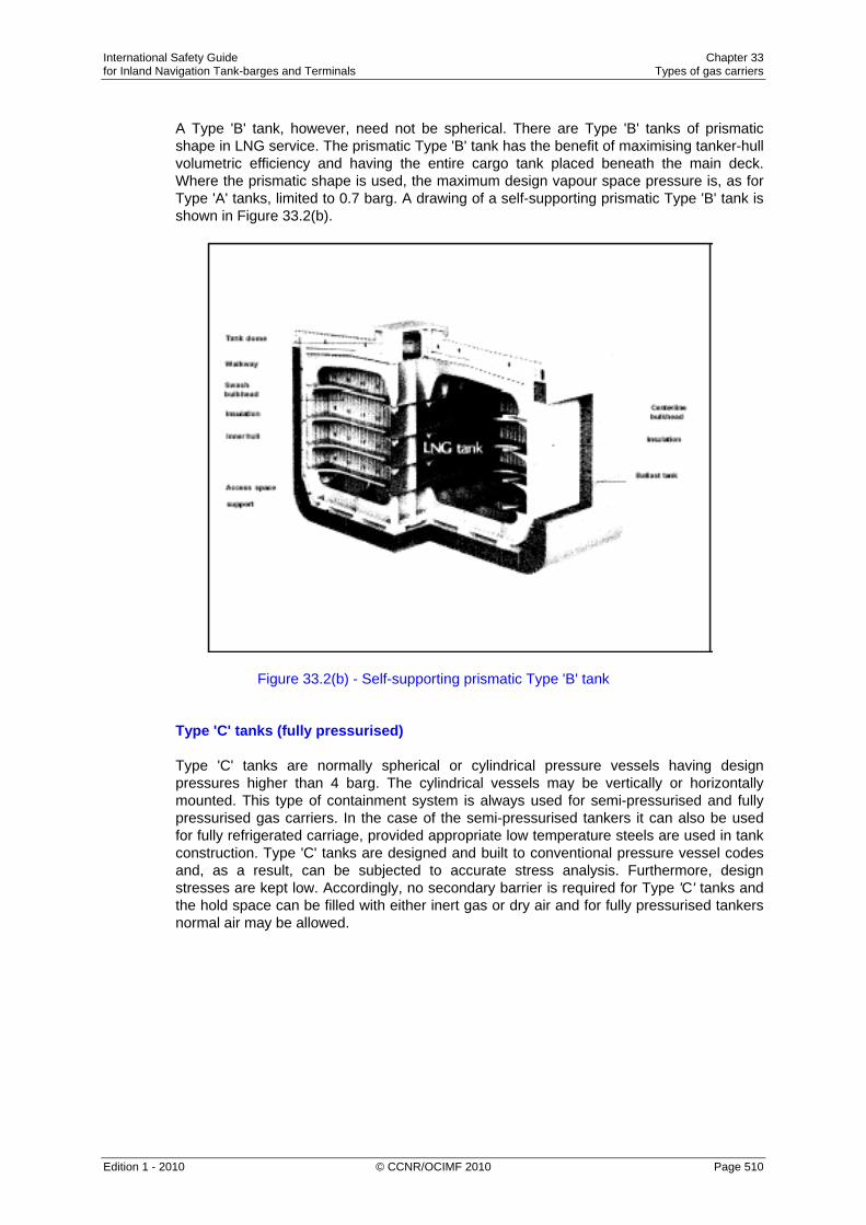
International Safety Guide Chapter 33 for Inland Navigation Tank-barges and Terminals Types of gas carriers
Edition 1 - 2010 © CCNR/OCIMF 2010 Page 510
A Type 'B' tank, however, need not be spherical. There are Type 'B' tanks of prismatic shape in LNG service. The prismatic Type 'B' tank has the benefit of maximising tanker-hull volumetric efficiency and having the entire cargo tank placed beneath the main deck. Where the prismatic shape is used, the maximum design vapour space pressure is, as for Type 'A' tanks, limited to 0.7 barg. A drawing of a self-supporting prismatic Type 'B' tank is shown in Figure 33.2(b).
Figure 33.2(b) - Self-supporting prismatic Type 'B' tank
Type 'C' tanks (fully pressurised) Type 'C' tanks are normally spherical or cylindrical pressure vessels having design pressures higher than 4 barg. The cylindrical vessels may be vertically or horizontally mounted. This type of containment system is always used for semi-pressurised and fully pressurised gas carriers. In the case of the semi-pressurised tankers it can also be used for fully refrigerated carriage, provided appropriate low temperature steels are used in tank construction. Type 'C' tanks are designed and built to conventional pressure vessel codes and, as a result, can be subjected to accurate stress analysis. Furthermore, design stresses are kept low. Accordingly, no secondary barrier is required for Type 'C' tanks and the hold space can be filled with either inert gas or dry air and for fully pressurised tankers normal air may be allowed.

International Safety Guide Chapter 33 for Inland Navigation Tank-barges and Terminals Types of gas carriers
Edition 1 - 2010 © CCNR/OCIMF 2010 Page 511
In the case of a typical fully pressurised tanker (where the cargo is carried at ambient temperature), the tanks may be designed for a maximum working pressure of about 18 barg. For a semi-pressurised tanker the cargo tanks and associated equipment are designed for a working pressure of approximately 5 to 7 barg and a vacuum of 0.3 barg. Typically, the tank steels for the semi-pressurised tankers are capable of withstanding carriage temperatures of -48°C for LPG or -104°C for ethylene. (Of course, an ethylene carrier may also be used to transport LPG.) Figure 33.3 shows Type 'C' tanks as fitted in a typical fully pressurised gas carrier. With such an arrangement there is comparatively poor utilisation of the hull volume; however, this can be improved by using intersecting pressure vessels or bi-lobe type tanks which may be designed with a taper at the forward end of the tanker. This is a common arrangement in semi-pressurised tankers as shown in Figure 33.4.
Figure 33.3.1 - Widely spread inland Figure 33.3.2 - Widely spread inland gas tanker-type, fully pressurised gas tanker-type, fully pressurised Double hull and double bottom Single hull 33.2.2 Membrane Tanks (Membrane - 0.7 to 1.5 mm thick)
The concept of the membrane containment system is based on a very thin primary barrier (membrane - 0.7 to 1.5 mm thick) which is supported through the insulation. Such tanks are not self-supporting like the independent tanks outlined in 33.2.1; an inner hull forms the load bearing structure. Membrane containment systems must always be provided with a secondary barrier to ensure the integrity of the total system in the event of primary barrier leakage. The membrane is designed in such a way that thermal expansion or contraction is compensated without over-stressing the membrane itself. There are two principal types of membrane system in common use both named after the companies who developed them and both designed primarily for the carriage of LNG. These two companies have now combined into one and future developments can be expected.
Water ballast in the hold space not advised when tanks are loaded
Water ballast

International Safety Guide Chapter 33 for Inland Navigation Tank-barges and Terminals Types of gas carriers
Edition 1 - 2010 © CCNR/OCIMF 2010 Page 512
GTT 96 Membrane system Figures 33.5(a) and 33.5(b) show the GTT 96 system comprising a thin lnvar primary barrier. lnvar is a stainless steel alloy containing about 36 per cent nickel and 0.2 per cent carbon. This is attached to the inner (cold) surface of perlite-filled plywood boxes used as primary insulation. These boxes have thickness of between 200 and 300 millimetres. These, in turn, are attached to an identical inner layer of lnvar (the secondary barrier) and, finally, a further set of similar perlite-filled boxes is used for secondary insulation. lnvar is chosen for the membranes because of its very low coefficient of thermal expansion, thus making expansion joints, or corrugation, in the barriers unnecessary. Newer designs of the GTT 96 system utilise lnvar membranes of 0.7 millimetres thickness in strakes of 0.5 metres width and strengthened plywood boxes to hold the perlite insulation. The perlite is processed with silicon to make it impervious to water or moisture. The thickness of the insulation boxes can be adjusted to obtain the required amount of boil-off. Figure 33.5(b) shows a section through the basic GTT 96 containment system.
Figure 33.5(a) – GTT 96 Membrane containment system - larger LNG carriers

International Safety Guide Chapter 33 for Inland Navigation Tank-barges and Terminals Types of gas carriers
Edition 1 - 2010 © CCNR/OCIMF 2010 Page 513
Figure 33.5(b) - Construction of the GTT 96 Membrane system
GTT Mk III The GTT Mk III system, shown in Figure 33.6(a), features a primary barrier of stainless steel (1.2 millimetres in thickness) having raised corrugations, or waffles, to allow for expansion and contraction. In the original Mark I design, the insulation that supports the primary membrane consisted of laminated balsa wood panels held between two plywood layers; the face plywood formed the secondary barrier. The balsa wood panels were interconnected with specially designed joints comprising PVC foam wedges and plywood scabs and were supported on the inner hull of the tanker by wooden grounds.
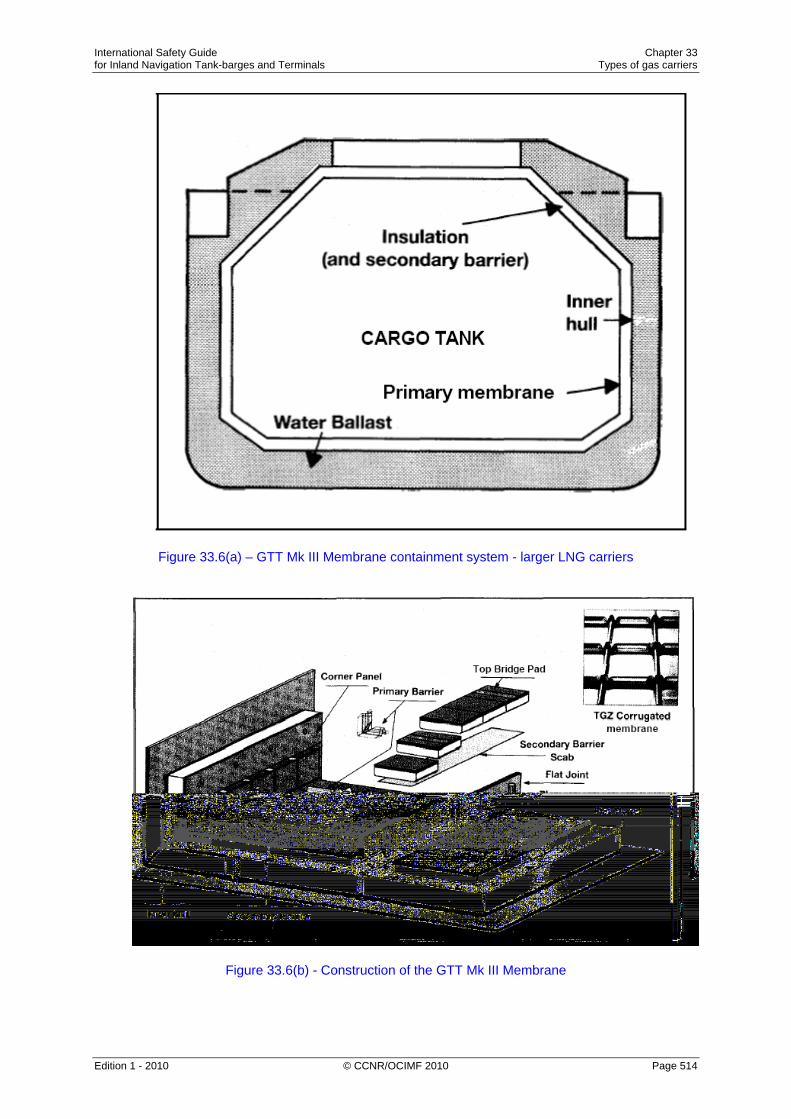
International Safety Guide Chapter 33 for Inland Navigation Tank-barges and Terminals Types of gas carriers
Edition 1 - 2010 © CCNR/OCIMF 2010 Page 514
Figure 33.6(a) – GTT Mk III Membrane containment system - larger LNG carriers
Figure 33.6(b) - Construction of the GTT Mk III Membrane

International Safety Guide Chapter 33 for Inland Navigation Tank-barges and Terminals Types of gas carriers
Edition 1 - 2010 © CCNR/OCIMF 2010 Page 515
In the Mark III design the balsa wood insulation is replaced by reinforced cellular foam. Within the foam there is a fibreglass cloth/aluminium laminate acting as secondary barrier. Figure 33.6(b) shows a cutaway section through the GTT Mk III containment system.
33.2.3 Semi-Membrane Tanks
The semi-membrane concept is a variation of the membrane tank system. The primary barrier is much thicker than that in the membrane system, having flat sides and large radiused corners. The tank is self-supporting when empty but not in the loaded condition. In this condition the liquid (hydrostatic) and vapour pressures acting on the primary barrier are transmitted through the insulation to the inner hull as is the case with the membrane system. The corners and edges are designed to accommodate expansion and contraction. Although semi-membrane tanks were originally developed for the carriage of LNG no commercial-size LNG carrier has yet been built to this design. The system has however, been adopted for use in LPG tankers and several Japanese-built fully refrigerated LPG carriers have been delivered to this design.
33.2.4 Integral Tanks Integral tanks form a structural part of the tanker's hull and are influenced by the same loads which stress the hull structure. Integral tanks are not normally allowed for the carriage of liquefied gas if the cargo temperature is below –10°C. Certain tanks on a limited number of Japanese-built LPG carriers are of the integral type for the dedicated carriage of fully refrigerated butane.
33.3 Materials of Construction and Insulation 33.3.1 Construction Materials
The choice of cargo tank materials is dictated by the minimum service temperature and, to a lesser degree, by compatibility with the cargoes carried. The most important property to consider in the selection of cargo tank materials is the low-temperature toughness. This consideration is vital as most metals and alloys (except aluminium) become brittle below a certain temperature. Treatment of structural carbon steels can be used to achieve low-temperature characteristics and the Gas Codes specify low-temperature limits for varying grades of steel down to -55°C. Reference should be made to the Gas Codes and classification society rules for details on the various grades of steel.

International Safety Guide Chapter 33 for Inland Navigation Tank-barges and Terminals Types of gas carriers
Edition 1 - 2010 © CCNR/OCIMF 2010 Page 516
According to the Gas Codes, tankers carrying fully refrigerated LPG cargoes may have tanks capable of withstanding temperatures down to -55°C. Usually, the final temperature is chosen by the shipowner, depending on the cargoes expected to be carried. This is often determined by the boiling point of liquid propane at atmospheric pressure and, hence, cargo tank temperature limitations are frequently set at about -46°C. To achieve this service temperature, steels such as fully killed, fine-grain, carbon-manganese steel, sometimes alloyed with 0.5 per cent nickel, are used. Where a tanker has been designed specifically to carry fully refrigerated ethylene (with a boiling point at atmospheric pressure of -104°C) or LNG (atmospheric boiling point -162°C), nickel-alloyed steels, stainless steels (such as Invar) or aluminium must be used for the material of tank construction.
33.3.2 Tank Insulation
Thermal insulation must be fitted to refrigerated cargo tanks for the following reasons: • To minimise heat flow into cargo tanks, thus reducing boil-off. • To protect the tanker structure around the cargo tanks from the effects of low
temperature. Insulation materials for use on gas carriers should possess the following main characteristics: • Low thermal conductivity. • Ability to bear loads. • Ability to withstand mechanical damage. • Light weight. • Unaffected by cargo liquid or vapour.
The vapour-sealing property of the insulation system, to prevent ingress of water or water vapour, is important. Not only can ingress of moisture result in loss of insulation efficiency but progressive condensation and freezing can cause extensive damage to the insulation. Humidity conditions must, therefore, be kept as low as possible in hold spaces. One method to protect the insulation is to provide a foil skin acting as a vapour barrier to surround the system.

International Safety Guide Chapter 33 for Inland Navigation Tank-barges and Terminals Types of gas carriers
Edition 1 - 2010 © CCNR/OCIMF 2010 Page 517
Material Application Thermal Conductivity
W/m K
Balsa Wood A load-bearing insulant 0.05
Mineral Wool Normally supplied in slabs or rolls 0.03
Perlite Granular silicon/aluminium oxide used as bulk in-fill for hold spaces or in modular boxes
0.04
Polystyrene Pre-formed, sprayed or foamed 0.036
Polyurethane Pre-formed, sprayed or foamed 0.025
Table 33.1 - Typical insulation materials Table 33.1 provides information on the insulation materials normally used in gas carrier construction, together with approximate values for their thermal conductivities at 10°C. Thermal insulation may be applied to various surfaces, depending on the design of the containment system. For Type 'B' and 'C' containment systems, insulation is applied directly to the cargo tank's outer surfaces. For Type 'A' cargo tanks insulation can be applied either directly to the cargo tank or to the inner hull (if fitted) although its application to the cargo tank is more common. As most insulation materials are flammable, great care is required at times of construction or refit to ensure that fires are avoided.

International Safety Guide Chapter 33 for Inland Navigation Tank-barges and Terminals Types of gas carriers
Edition 1 - 2010 © CCNR/OCIMF 2010 Page 518

International Safety Guide Index for Inland Navigation Tank-barges and Terminals
Edition 1 - 2010 © CCNR/OCIMF 2010 Page 519
INDEX
A
Access equipment 16.4.3 responsibility to provide 16.4.2 tanker/shore 16.4 unauthorised persons 16.4.7
Accommodation air conditioning and ventilation systems 24.2 closure of openings 24.1
Additives Anti-static 11.1.7.9 Antistatic, Inhibitors, Dyes, H2S
Adiabatic - definitions compression 27.16; 27.21.2 curve 27.16 expansion 27.16
Adjacent berths general cargo tankers at 24.9.2 tankers at 24.9.1
Administration - definitions Legislation 1.2.5 Setting of exposure limits 2.3.3.2 Definition of dangerous areas 4.4.2.1
Aerials - see Antennae, transmitting
Air conditioning central 4.1; 11.4.3; 24.2 window type units 11.4.3; 24.2
Air Draught Restrictions on 15.6.4 Retention of ballast to reduce 11.6.6
Air driven lamps precautions for use 4.3.3; 12.5.4
Air flow over accommodation block Figure 2.4
AIS status during cargo operations 4.8.4
Alarms cargo tank overfill 11.1.6.6; 11.1.13.4 emergency 20.2.3.1 fire 19.3; 19.4 gas measurement instruments 2.3.6.4; 8.2.3; 8.2.4; 19.2.9 pumproom 10.11.6; 10.11.7 vapour balancing during tanker-to-tanker transfers 7.1.6.4
Alongside barges 11.9.2 tugs 23.3.2 tugs and other craft 24.9.4 - see also Tugs
Aluminium anodes 4.7 equipment 4.6 fire protective clothing 19.7
Anchors readiness 23.3.1 securing 23.4.2.5
Anodes - see Aluminium, Cathodic protection
Antennae, transmitting precautions for use 4.8.2.1 satellite equipment 4.8.2.3

International Safety Guide Index for Inland Navigation Tank-barges and Terminals
Edition 1 - 2010 © CCNR/OCIMF 2010 Page 520
Antistatic additive - definitions use of 11.1.7.9
Approved equipment - definitions alterations to 4.4.4.5 communications 4.8.1 fixed electrical 4.4.3 gas measurement 2.4 portable electrical 4.3; 12.5.4
Aqueous film forming foam (AFFF) use of 5.3.2.1
Area classification electrical equipment/installations 4.4 - see also Dangerous area; Hazardous area
Arms - see Metal cargo arms
Aromatic hydrocarbons benzene and others 2.3.5 - see also Benzene
Asbestos removal of lagging 4.11 respiratory hazards 10.2.2
Atmosphere cargo tank control 7.1.5 cargo tank washing and cleaning 11.3.4 inert 7.1.6; 11.3.4.1 non-inert 11.3.4.2 - see also Measuring and sampling; Sampling
Auto-ignition - definitions of petroleum liquids 4.10
Automatic Identification System - see AIS
B
Ballast cleaning contaminated spaces 11.3.6.11 contamination of double hull spaces 11.7 deballasting in port 11.6.5 loading into cargo tanks 11.6.3 operations 11.6 retention to reduce freeboard 11.6.6.1 simultaneous cargo/ballast 7.1.6.3; 11.1.14.12 tank lids 24.5 valve operations 11.6.3.2 - see also Segregated ballast
Ballast spaces monitoring of 7.3.4
Ballast tanks over or under pressurisation 7.2.2
Barges - see Alongside, Boats alongside
Battery equipment portable 4.3.4; 4.3.5; 4.3.6
Bearings cargo pump, inspection of 10.11.1; 10.11.7
Benzene and other aromatic hydrocarbons 2.3.5 cargo information 2.3.4; 22.4.1.2; 22.4.2.1 in enclosed spaces 10.2.4.1 toxicity 2.3.5.2
Berthing exchange of information 22.3 fender operating limits for 17.2
Berths mooring at 9.8.5; 16.2; 23.4 vehicle access to 24.13 - see also Adjacent berths; Jetty
Bilges pumproom, alarm 10.11.7 pumproom, cleanliness of 10.11.3

International Safety Guide Index for Inland Navigation Tank-barges and Terminals
Edition 1 - 2010 © CCNR/OCIMF 2010 Page 521
BLEVE definition 27.22; vapour burn 30.1.1
Boats alongside during an emergency 9.9.3.1 during cargo operations 24.9.4 during tank cleaning 11.3.3.2 - see also Tugs
Boil-off - definitions cargo 32.5.2; 32.6; 33.3.2 compressed, condensed, returned to the tank 31.5.2 control 31.5 flash-gas 32.7.2 heat flow 32.7.2; 33.3.2 insulation boxes 33.2.2 LNG storage tanks 27.2.1 loading 31.5 rates 27.18.1 reliquefaction 31.1.1 semi-pressurised cargo of propane 27.21.2 tank pressures 32.7.2 vapours 27.13; 27.21.1; 27.21.2; 31.5; 31.5.2; 32.4
Boiling Point - definitions atmospheric pressure 27.1; 27.2.1; 27.12.1 BLEVE 27.22 cargo 32.5.3; 33.1 ethane 27.19 ethylene 33.3.1 in (M)SDS 20.1 liquefied gas 27.12.2; 27.15 liquid mixture 27.19 LNG 27.2.1; 33.1; 33.3.1 loading heated cargo 11.1.11 Net Positive Suction Head (NPSH) requirement 31.2 of compounds 1.1.1 pressure 27.17; 32.5.3 propane 33.1; 33.3.1 special boiling point solvents 2.3.5.1 temperature limitations 33.3.1 values 27.18.1 vapour 27.15, 27.22 vinyl chloride 27.2.4
Bonding - definitions in terminal 17.6 tanker/shore cable/wire 17.5.2; 17.5.4 static electricity Chapter 3 tank cleaning hoses 11.3.6.1; 11.3.6.2
Booster Pump - definitions cargo tank pumps 31.2; 32.7.3; Figure 32.13 cavitate 32.7.4 centrifugal type 31.2; 32.7.2 deck-mounted 31.2 discharging 32.7; 32.7.2 fully pressurised tankers 31.2 heater 32.7.3 in-line equipment fitted to terminal pipeline systems 32.5.3 pressure increase 32.5.3 reduce the pressure 32.7.2 suction 32.7.3 throttling 32.7.2 vertical, horizontal Figure 31.8; 31.9 weatherproof covering 31.8
Breathing apparatus air line 10.8.2 cartridge/canister face masks 10.8.4 emergency escape breathing device 10.3; 10.8.3; 10.11.7 hose mask (fresh air) 10.8.5 maintenance 10.8.6 readiness for enclosed space entry 10.5 self-contained 10.8.1 stowage 10.8.7 training 10.8.8
Bulk Cargo - definitions
Bunkering operations Chapter 25 procedures 25.2 safety check-list 25.4
Bunkers checking of headspace for flammability 4.1 hazards associated with 2.7 information exchange 22.2.3; 22.4.1 - see also Residual fuel oil

International Safety Guide Index for Inland Navigation Tank-barges and Terminals
Edition 1 - 2010 © CCNR/OCIMF 2010 Page 522
Butane calibration of flammable gas monitors 2.4.3.4 Explosive Limits of 1.2.2 Table 1.1;
Butterfly valves pressure surge 11.1.5 see also Valves
C
Cables ship/shore bonding 17.5.2; 17.5.4 - see also Wandering leads
Cannons - see Monitors
Cans petroleum in 12.5 - see also Drums
Carbamates - definitions ammonia 27.7; 32.2.3; 32.9.5 carbon dioxide 27.7; 32.9.5 cargo contamination 27.7
Carbon dioxide as product of inert gas 7.1.3electrostatic hazard 3.3.6 fire-fighting 5.3.2.2; 19.5.2 flooding 8.1.3.1 use as span gas 2.4.10.1
Carbon monoxide as product of inert gas 7.1.3
Carcinogen - definitions permanent damage 28.3.1 vinyl chloride 28.3.1
Cargo deck 12.5.8
distribution 22.5; 22.6 handling Chapter 7, Chapter 11; Chapter 24; 26.3 information 22.2.4; 22.4.2 leakage into ballast spaces 11.3.6.11; 11.7 MSDS 2.3.4; 20.1 operations, not always afloat 16.7 operations, over the tide 16.6 packaged 12.5 pipeline draining 10.11.2 tank lids 24.3.1 toxicity 2.3 - see also Discharging; Hoses; Loading; Manifolds; Measuring and sampling; Metal cargo arms; Pipelines; Pumps; Tank; Valves
Cargo Area - definitions
Cargo arms - see Metal cargo arms
Cargo Containment Systems - definitions cool-down 32.4 design chapter 33 gas carriers 33.1 independent tank type membrane type 33.1 pressure drop 32.4 total arrangement for containing cargo 33.2
Cascade Reliquefaction Cycle - definitions condense cargo vapours 31.5.2 ethylene 27.2.1 heat exchangers 27.2.1 methane 27.2.1 propane 27.2.1 pure refrigerant cascade process 27.2.1 refrigerant compressor 27.2.1; 31.5.2 simplified Figure 31.13
Cathodic protection - definitions anodes in cargo tanks 4.7 hull/jetty 17.5.2 use during tanker-to-tanker transfers 11.9.5

International Safety Guide Index for Inland Navigation Tank-barges and Terminals
Edition 1 - 2010 © CCNR/OCIMF 2010 Page 523
Cavitation - definitions centrifugal pump 32.7.4 flow rate 31.2 impeller 31.2 minimum head of cargo 31.2 pump 31.2
Certificate of Fitness - definitions gas codes 32.5.1 guidance 32.5.1 particular grades of cargo 31.2 pump design 31.2 stability conditions .32.5.1 survival requirements 32.5.1
Certified Gas Free - definitions hot work 4.4.5.3
Check-lists bunkering safety 25.4 tanker/shore safety 26.3
Chemical indicator tubes toxic gases, measurement of 2.4.7.1
Cigarette lighters precautions for use 4.2.2.4
Cleaning liquids precautions for use 12.2.4
Climatic conditions cold weather precautions 7.1.11; 7.2.2.2; 7.2.2.4 electrical storms 16.3; 26.1.3 lightning 17.6; 26.1.3 still air/wind 2.5.5; 11.1.8; 11.1.9.2; 26.1.2
Clingage - definitions In cargo arms 18.1.2
Closed discharging operations 11.1.14.3
Closed loading cargoes containing benzene 2.3.5.2; 11.1.10 cargoes containing H2S 2.3.6.4; 11.1.9.2 operations 11.1.6.6 very high vapour pressure cargoes 11.1.8
Closed operations - definitions
Clothing electrostatic hazard 3.3.7 of synthetic materials 26.2.4 protective 19.7
Cold weather precautions 7.1.11; 7.2.2 - see also Climatic conditions
Cold work - definitions electrical repairs 4.4.5.2 on pipelines 9.4.4.5 precautions 10.2.3
Combustible (flammable) - definitions Chamber 2.4.3.5 Metals 5.2.4, 8.1.4.1 Mists 2.4.3.2
Combustible gas detection - see gas detection
Combustible gas indicator (explosimeter) - definitions area testing 2.7.3.2; 4.5.1; 7.1.6.12; 8.2; 10.3; 11.4.4 dilution tubes 2.4.3.4 non-catalytic heated filament type 2.4.4 pellistor type 2.4.3
Combustion equipment maintenance 4.2.4.1
Command centre emergency organisation 9.9.2.2

International Safety Guide Index for Inland Navigation Tank-barges and Terminals
Edition 1 - 2010 © CCNR/OCIMF 2010 Page 524
Communications Chapter 22 bunkering 25.2 closed circuit television 4.4.3.2 enclosed space entry 10.5 equipment 4.8; 22.1.1 language difficulty 22.1.2 mobile telephones 4.8.6 pagers 4.8.7 pre-arrival 16.1; 22.2 pre-berthing 22.3 procedures 22.1.2 pumproom entry 10.10.2 radio 4.8.2 satellite 4.8.2.3 tanker to barge 11.9.2 tanker to ship 11.9.4 telephones 4.8.5; 22.1.1; terminal emergency 20.2.3; 20.4 UHF/VHF 4.8.2.2; 22.1.1; 22.1.2 vapour emission control 11.1.13.10
Compression Ratio - definitions compressor discharge temperature 31.5.2 inter-stage cooling 31.5.2 two-stage cycle 31.5.2
Condensate - definitions dryness fraction 27.21.2 enthalpy 27.21.2 extracted 27.2.1 liquid 27.15 NGL 27.2.1 raw feed gas 27.2.1 reliquefaction 31.1.1; 32.6; 32.8 reservoirs 27.2.1 vapour 32.5.2; 32.6
Contractors management of 9.7
Craft alongside - see Alongside, Boats alongside
Critical Pressure - definitions critical temperature 27.14
liquid state 27.14 Table 27.5
Critical Temperature - definitions critical pressure 27.14 gas 27.15 physical properties Table 27.5 pressures 27.14
Cryogenics - definitions
D
Dalton’s Law of Partial Pressures definition 27.19 vapour pressure of liquid mixtures 27.19
Dangerous area - definitions description of 4.4.2 electrical equipment in 4.4 work permits 19.1.3 - see also Area classification, Hazardous area
Dangerous goods - Definitions
Deballasting - see Ballast
Deck cargo carriage of 12.5.8
Deck water seal correct function 7.1.5.2 freezing of 7.1.11.3
Deepwell Pump - definitions booster pump 31.8 cool-down 31.2; 32.4

International Safety Guide Index for Inland Navigation Tank-barges and Terminals
Edition 1 - 2010 © CCNR/OCIMF 2010 Page 525
gas carriers 31.2 loading 31.2 pump performance curve 31.2; Figure 31.3 typical Figure 31.6
Density - definitions air 32.2.3 carbon dioxide 27.2.4 cargo 27.18.1 difference 32.2.3 ensuing vapour cloud 27.12.3 gas 1.3; 2.2; 2.5.2.1 gas mixture 27.19; Table 27.7 inert gas 32.2.3 layering 27.18.1 liquefied gas 27.18.1 liquid Table 27.5; 27.18.1; 31.2 propane 32.5.5 relative 32.5.5 saturated vapour 27.17 temperature 27.18.2 vapour 27.18.2; 27.19; 32.3 variations of propane liquid 27.17
Derricks hose handling 22.3.2 inspection and maintenance 8.3.1
Detonation arrestor vapour emission control systems 11.1.13.6
Dew point - definitions ammonia 32.9.5 bubble point 27.20; Figure 27.17 cold cargo loading 27.7 condense 27.20 drying 32.2.2 inert gas compositions Table 27.4 inert gas generator 32.2.2 operational difficulties 27.7 refrigerated dryer 32.2.2 vapour mixture 27.20
Dilution tubes discourage use of 2.4.3.4
Dipping inerted cargo tanks 7.1.6.6 electrostatic hazards 3.2.1; 11.8.2
Discharging cargo 11.1.14 closed 11.1.14.3 commencement of 11.1.14.7 electrostatic hazards 11.1.14.14; 16.11.4 gas freeing/tank cleaning concurrently 11.3.6.4 inert gas procedures 7.1.6.6; 11.1.14.4 information exchange 22.4.2.2; 22.6; over the tide 16.6.1 periodic checks 11.1.14.10 rates 11.1.14.11; 22.4.2.2 stability 11.2
Dispersion gas, evolution and 2.5.3; 2.5.4
Double banking management of operation 16.5
Double bottom tanks cleaning contaminated 11.3.6.11 impact on stability 11.2.2 loading bunkers into 25.2 ventilating 11.4.7
Double hull tankers cargo leakage 11.7 inerting double hull tanks 11.7.2 ventilating procedures 11.4.7; 11.7.1
Drain plugs inspection of 10.11.1
Drip pans/trays spill containment 24.7.4
Drugs and alcohol policy 13.4 trafficking 13.5
Drums precautions, handling/stowing 12.5.1; 12.5.8

International Safety Guide Index for Inland Navigation Tank-barges and Terminals
Edition 1 - 2010 © CCNR/OCIMF 2010 Page 526
Dry chemical powder - definitions compatibility with foam 5.3.2.1 flame inhibitor 5.3.3.1 use on class ‘B’ fires 5.2.2 use on class ‘C’ fires 5.2.3 - see also Fire-fighting
Dunnage use of 12.5.1.2; 12.5.8
E
Earthing (grounding) - definitions electrostatic hazards 3.2.2; 11.8.2.2 in terminal 17.6 tanker/shore 17.5.2; 17.5.4 stays/derricks/booms 4.8.2.1
Electric cables - see Wandering leads
Electrical currents tanker/tanker 11.9.5 tanker/shore 17.5.2
Electrical equipment alterations 4.4.4.5 at terminals 4.4.3.4; 17.1 in dangerous areas 4.4 in enclosed spaces 10.9.4 in pumproom 10.11.4 installations 4.4 insulation testing 4.4.4.4 maintenance 4.4.4 on board ship 4.4.3.3 permit to work 17.1 portable 4.3; 10.9.4; 12.5.4 repairs 4.4.5 welding and burning 9.5; 9.8.13
Electrical storms electrical storms 16.3; 26.1.3
Electrostatic - see Static electricity
Emergency command centre, tanker 9.9.2.2 communications 20.2.3.3 control centre, terminal 20.2.2 escape routes 21.2.1; 24.10.2 evacuation Chapter 21 medical facilities 20.2.7.4 organisation 9.9.2.2; 20.2.2 plans 9.9.2; 20.2; 20.4 preliminary action 9.9.2.3 preparedness, terminal Chapter 20 procedures Chapter 20; 10.6; 26.5 release of cargo hose/arm 18.1.10; 24.6.5 release of ship; 26.5.4 removal from berth 20.5; 26.5 services 20.2.7 shutdown 11.1.6.3 signals 22.1.2; 22.4.1.1; 22.4.2.1; 22.4.2.2; 22.5; 22.6; 25.2 towing-off pennants 26.5.5 training and drills 9.9.2.7; 21.4
Enclosed spaces - definitions entry into Chapter 10, 7.1.6.12; 7.1.7.3; 12.5.3 evacuation from 10.6.1 gas freeing 11.4.2 inspection of 24.4 oxygen deficiency 10.2.5 permits to work in 9.3; 10.4 respiratory hazards 10.2.2 toxic hazards 10.2.4
Endothermic - definitions
Engine room control of potential ignition sources 4.2.4
Enthalpy - definitions condensate 27.21.2 condenser 27.21.2

International Safety Guide Index for Inland Navigation Tank-barges and Terminals
Edition 1 - 2010 © CCNR/OCIMF 2010 Page 527
heat 27.21.2 liquefied gases 27.21.1 reliquefaction 27.21; 27.21.2 thermodynamic heat 27.21.1 vapour 27.21.2
Entropy - definitions adiabatic process 27.21.2 constant 27.16; 32.6.1 reversible process 27.16 pressure 27.16
Entry permit - definitions - see also Enclosed spaces; Permit to work system
Explosimeter - see Combustible gas indicator
Explosion-proof (flame-proof) - definitions cable attachment 4.3.2 inspection of fittings 4.4.4.6
F
Fans gas freeing 11.4.5; 11.4.6 pumproom ventilation 10.11.5
Fendering jetty fendering systems 17.2 operating limits for berthing 22.3.2 of tugs and other craft 23.3.2; 24.9.4
Filters electrostatic hazards 3.1.2; 3.3.1; 11.1.7.10 in sample lines 2.4.13.3
Fire alarm 9.9.2.4; 9.9.3.1; 19.3; 26.5.2 alongside a terminal 26.5.2 class ‘A’, combustible material 5.2.1
class ‘B’, hydrocarbon 5.2.2 class ‘C’, electrical equipment 5.2.3 class ‘D’, combustible metals 5.2.4 connection, international shore 8.1.2; 19.5.3.5; 19.6; 26.5.3; Figure 26.2 control plans 9.9.2.5 instructions notice Figure 26.1 on berth 26.5.1 pumps at a terminal 19.5.3.2 training and drills 9.9.2.7; 21.4 types of 5.2 wires 26.4(4); 26.5.5
Fire-fighting blankets in galley 4.2.3 cannons (monitors) 19.5.2; 19.5.3.8 carbon dioxide 5.3.2.2 carbon dioxide extinguishers 19.5.2 carbon dioxide flooding 8.1.3.1 cooling, fixed systems 5.3.1; 8.1.2 dry chemical extinguishers 5.3.3.1; 12.5.6; 19.5.2; 24.8 emergency services 20.2.7 equipment, access to 20.2.5 equipment, maintenance 9.9.2.6 equipment, readiness of 9.9.2.6; 19.2.2; 24.8 extinguishers 8.1.4; 12.5.6; 19.5.2 fixed system 8.1.2; 8.1.3; 19.5.3 foam 5.2.2; 5.3.2.1; 8.1.3.2; 19.5.2; 19.5.3.7; 19.5.3.8 hoses 8.1.2; 19.5.3.3; 24.8 Hot Work precautions 9.4.3.1 hydrants 8.1.2; 19.5.3.3; 19.5.3.4; 19.5.3.7 inert gas system 8.1.3.5 monitors (cannons) 19.5.2; 19.5.3.8 packaged cargo 12.5.5; 12.5.6 plans, tanker 9.9.2.5 plans, terminal 20.2.4 protective clothing 19.7 pumproom 10.11.7 sand 5.3.2.4; smothering systems 5.3.2; 8.1.3; 12.5.5 steam 5.3.2.3 tanker equipment 8.1 terminal equipment 19.5; 19.6 theory and equipment Chapter 5 tugs 19.6 water 5.2.1; 5.3.1.1; 8.1.2; 19.5.3; 19.6; 26.5.3

International Safety Guide Index for Inland Navigation Tank-barges and Terminals
Edition 1 - 2010 © CCNR/OCIMF 2010 Page 528
water-borne equipment 19.6 water curtain 8.1.3.4 water fog 8.1.3.3
Flame arrester - definitions Tank over-pressurisation 7.2.2.2
Flame inhibitors dry chemical powder 5.3.3.1 general 5.3.3 vaporising liquids (halons) 5.3.3.2
Flame screen - definitions cold weather precautions 7.1.11.3; 7.2.2.2 on openings/vents 2.7.4.2; 7.1.12.3; 11.1.14.3; 24.3.2
Flame-proof - see Explosion-proof
Flammability bunker headspace 2.7.3 classification, petroleum liquids 1.2.6 composition diagram, hydrocarbon/inert gas mixture Figure 1.1 general 1.2 residual fuel oil 2.7 tests for 1.2.4 vented gas 2.5.5
Flammable - definitions gas, detection 2.4.2; 2.4.8; 8.2.8; 10.10.2; 19.2.7; 19.2.9; 24.2 gas dispersion 2.5.3; Figure 2.3 (a)(b)(c) gas, general 2.5.1; 7.1.1 gas, venting 11.4.3 limits Figure 1.1; 1.2.2; 1.2.3; 2.4; 2.5.3; 2.5.4; 7.1.1 range definitions; 1.2.3; 7.1.1 zones, near accommodation block Figure 2.5 - see also Flammability
Flange insulating 17.5.2; 17.5.5; Figure 17.1 tanker/shore cargo 18.1.3; 18.2.7; 24.6.1;
24.6.2; 24.6.3 vapour manifold 11.1.13.2
Flashlight (torch) - definitions use of 4.3.4
Flashpoint - definitions class ‘B’ fires 5.2.2 classification 1.2.5; 1.2.6 fuel oil 2.7; 2.7.3 loading over the top 11.1.12 reporting of 22.4.1.2; 22.4.2.1 test 1.2.5
Flexible cables - see Wandering leads
Flue gas inert gas composition and quality 7.1.3;
Foam (froth) - definitions concentrate definitions; 5.3.2.1 cooling 5.3.1.2 extinguishers 19.5.2 fire-fighting, theory and equipment Chapter 5 fixed installation 8.1.3.2; 19.5.3.7 mains 19.5.3.3 monitors (cannons) 19.5.3.8 petroleum fires, use on 5.2.2 solution definitions; 5.3.2.1; 19.5.3.7
Fog water fog definitions; 5.2.2; 5.3.1.1; 8.1.3.3
Footwear static charge 3.3.7
Free fall - definitions precautions 3.3.3; 7.1.12.3; 11.3.6.5
Free surface effect double hull tankers 11.2.2

International Safety Guide Index for Inland Navigation Tank-barges and Terminals
Edition 1 - 2010 © CCNR/OCIMF 2010 Page 529
Freezing inert gas piping 7.1.11 fire hydrants 8.1.2 fire-main 19.5.3.3 metal arms, cargo 18.1.5 pressure/vacuum valves 7.1.11.3; 7.2.2.2 steam winches/windlasses 23.4.2.1
Froth - see Foam
Funnel fire/sparks 4.2.4.1
G
Galleys equipment, safe operation of 4.2.3 steam cookers/boilers 4.2.3 stoves 4.2.3
Gangways access 16.4 aluminium 4.6 inspection/maintenance 16.4.6; 17.3.1 safety nets 16.4.5 siting 16.4.4
Garbage disposal facilities 9.8.6 storage 12.4.2
Gas cylinders 12.1; 12.5.1.2 density 1.3; 2.2; 2.5.1; 2.5.2.1 detection 2.4; 8.2; 10.11.7; 19.2.7; 19.2.8; 19.2.9; 19.4; 24.2 dispersion 2.5.3; 2.5.4 evolution 2.5.1; 2.5.2 flammability 1.2.4; 1.2.6; 2.1; 7.1.1 flue 2.3.9; 7.1.3 free definitions; 2.5.2.5; 2.5.4; 2.5.5; 7.1.6.11; 11.4 free certificate definitions; 9.8.9; 22.7.1.2 freeing 2.5.2.5; 2.5.5; 7.1.6.11; 11.4
indicators 2.4; 8.2 indicators, catalytic filament 2.4.3; Figure 2.1 indicators, infra-red 2.4.6; Figure 2.2 indicators, non-catalytic heated filament 2.4.4 inert 7.1 liquefied, packaged 12.1 masks, canister 5.3.2.2; 10.8.4 masks, hose type 10.8.5 measurement (toxic) 2.4.7; 11.8.4 measuring equipment 2.4; 8.2 meter, refractive index 2.4.5 sampling, filters 2.4.13.3 sampling, lines 2.4.13 sampling, procedures 2.4.13.2; 10.3 tests, for entry Chapter 10; 2.4; 7.1.6.12; 11.4.2; tests, for tank washing 11.3.5 venting 2.5; 11.1.6.6; 11.4.3
Gas Codes - definitions avoidance of ignition sources 27.5 best practice 31.1.4 cargo tank 31.9.1 Certificate of Fitness 32.5.1 electrical installations 31.8 fully refrigerated LPG 33.3.1 gas carriers 33.1 isolating valves for cargo tanks 31.1.2 low-temperature limits 33.3 pressure monitoring 31.9.3 pressure relief valves 27.22 reliquefaction 31.5.1 tank filling limit 32.5.3 various grades of steel 33.3.1 vent risers 31.1.1
Gas-Dangerous Space or Zone - definitions electrical equipment 31.8
Gas-Freeing - definitions enclosed spaces 28.7.1 procedures 27.23

International Safety Guide Index for Inland Navigation Tank-barges and Terminals
Edition 1 - 2010 © CCNR/OCIMF 2010 Page 530
Gassing-up - definitions cargo supplied from the shore 32.3 cooling plant 32.3 difficulties 32.4 enclosed spaces 28.7.1 incondensible gases 32.5.4 inerting levels 27.7 liquid 32.3 non-flammable condition 32.2.3 using liquid from shore Figure 32.3(a) using vapour from shore Figure 32.3(b) vapour 32.3; 32.9.1
Gauging closed 11.1.6.6; 11.1.13.4; 11.8 - see also Measuring and sampling
General cargo berth, tanker operations at 24.9.3 tankers, at adjacent berth 24.9.2
Glands inspection of pump 10.11.1
Grounding - see Earthing
H
Halon - definitions replacement by foam 5.3.1.1
Harbour authorities in an emergency 20.2.7.1
Harness safety, use of 10.5
Hazardous area - definitions at a terminal 4.4.2.2 cold work 4.4.5.2
communications equipment 4.8 electrical equipment 4.3; 4.4 Hot Work 4.4.5.3; 9.4.4 permit to work 9.3 tanker at a berth 4.4.2.3 - see also Hazardous zone
Hazardous zone - definitions - see Hazardous area; Dangerous area
Heated products loading 11.1.11
High vapour pressure cargoes discharging 11.1.14.5 loading 2.5.2; 11.1.8
High velocity vent valves cold weather precautions 7.2.2 tank outlets 2.5.5; 24.3.3 use during closed loading 11.1.6.6
Holds - see Enclosed spaces
Hoses cargo 3.2.2; 11.9.5; 17.5.2; 18.2 clearing 11.1.15 emergency release of 24.6.5 fire 8.1.2; 19.5.3 flange 11.1.13.2; 18.2.7 flow velocities 18.2.5; Table 18.1; handling/lifting/suspending 18.2.11 inspection and testing 18.2.6 marking 18.2.4 pressure ratings, explanation 18.2.6.6 retirement criteria 18.2.6.5 storage 18.2.9 tank cleaning 11.3.5.2; 11.3.6.2; 11.3.6.3 weights 18.2.11
Hot Work - definitions conditions 9.4; 11.4.8 control of 4.4.5.3; 9.4.1 electrical repairs 4.3.2; 4.4.5.3 fire-fighting equipment 9.4.3.1 general 9.4 in cargo tanks 9.4.4.2

International Safety Guide Index for Inland Navigation Tank-barges and Terminals
Edition 1 - 2010 © CCNR/OCIMF 2010 Page 531
in dangerous or hazardous areas 9.4.4 on open deck 9.4.4.3 on pipelines 9.4.4.5 permit definitions; 9.3; 9.4.1; 9.4.3.1; 19.1.3
Human element considerations onboard Chapter 13 fatigue 13.3.2 see also Manning
Hydrocarbon gas - definitions catalytic filament combustible gas indicator 2.4.3; Figure 2.1 density 1.3; 2.2 detection 2.4; 8.2; 19.4 dispersion 2.5.3; 2.5.4 evolution 2.5.1; 2.5.2 evolution and dispersion 2.5 flammability 1.2; Figure 1.1 in enclosed spaces 10.2.3 indicators 2.4 inert gas mixture, flammability composition diagram Figure 1.1 measurement 2.4.2; 7.1.6.10; 10.3 non-catalytic filament indicator 2.4.4 refractive index meter 2.4.5 tests for entry 2.4; 7.1.6.12; 11.4.2 toxicity 2.3
Hydrocarbons aromatic 2.3.5
Hydrogen sulphide general 2.3.6 in bunker fuel 2.7.5 precautions 2.3.6; 2.6; 2.7.5; 10.2.4.2; 11.1.9 reporting presence of 22.4.1.2; 22.4.2.1 respiratory hazards 2.3.6.3; Table 2.1; 10.2.2
Hygiene personal 26.2.3
I
Ice formation in fire hydrants 8.1.2 on ballast vents 7.2.2 on metal arms 18.1.5 - see also Climatic conditions; Freezing
IGS - see Inert gas system
Incendive spark anodes 4.7 connection/disconnection of hoses/arms 17.5.2 gas indicators 2.4.3.5 portable tank washing machines 11.3.6.1 use of tools 4.5; 22.7.3
Induced charge electrostatic Chapter 3
Inert condition - definitions dipping/ullaging/sampling in 11.8.3; 24.4 fixed inert gas systems 7.1 for crude oil washing 7.1.6.9 for handling static accumulator oils 11.1.7.2 for tank washing 7.1.6.9 inspection of tanks in 7.1.6.12; 7.1.7.2; 10.2.5; 24.4
Inert gas - definitions assistance in fire-fighting 8.1.3.5 ballast passage 7.1.6.7 cold weather precautions 7.1.11 composition 7.1.3 effect on flammability 1.2.3; Figure 1.1 electrostatic charge, precautions 3.3.5; 11.8.3.1 failure of 7.1.12 health hazard 7.1.7 hose clearing 11.1.15.4 leakage 7.1.6.5; 7.1.6.12 maintenance of supply 7.1.6.6 plant definitions, 7.1.5.2, 7.1.6.2, 7.1.13, 7.1.6.8 pressurising 7.1.5; 7.1.8

International Safety Guide Index for Inland Navigation Tank-barges and Terminals
Edition 1 - 2010 © CCNR/OCIMF 2010 Page 532
procedures 7.1.5; 7.1.12; 11.1.6.5; 11.1.14.4 product carriers 7.1.12.3 purging 1.2.3; 2.5.2.4; 7.1.6.10 quality 7.1.3 repairs to system 7.1.13 residual fuel oil tanks 2.7.4.4 scrubbers 7.1.13 sources of 7.1.2 system (IGS) definitions; 7.1 topping up 7.1.6.5; 7.1.6.7 toxic components 7.1.3; 7.1.7; 10.3 water seal 7.1.5.2; 7.1.11.3; 7.1.13
Inerted tanks entry into 7.1.6.12; 7.1.7.3; 24.4 inspection of 7.1.6.12; 7.1.7.2; 10.2.5; 24.4 Inerting - definitions double hull spaces 11.7.1 tanks 7.1.4; 7.1.5; 7.1.6.1
Information exchange of Chapter 22
Insulating flange - definitions tanker/shore 11.1.13.8; 11.9.5; 17.5.5; Figure 17.1) testing 17.5.5.2
Insulation electrical, testing of 4.3.1; 4.4.4.4
Interface detector - definitions precautions for use 11.3.5.2
International shore fire connection use of 8.1.2; 19.5.3.5; 19.6 description of 26.5.3; Figure 26.2
Intoxicated persons 16.4.8
Intrinsically safe - definitions equipment, use of 4.3; 4.8
Iron sulphide, pyrophoric - see Pyrophoric iron sulphide
Isothermal - definitions compression 27.16 compressor 27.16 gas laws 27.16
J
Jetty access 9.8.6; 16.4; 19.8 fendering capacity 17.2 mooring at 23.4 traffic movement and control 19.8; 20.2.6
L
Lamps air driven 4.3.3; 12.5.4 portable 4.3
Language difficulties avoiding 22.1.2
Latent Heat - definitions condensation 27.12.1; 27.13 flash evaporation 27.21.2 fusion 27.12.1 pressure 27.12.1 solidification 27.12.1 substance in changing state 27.12.1 total internal energy of a fluid 27.21.1
International Safety Guide Index for Inland Navigation Tank-barges and Terminals
Edition 1 - 2010 © CCNR/OCIMF 2010 Page 533
Latent Heat of Vaporisation - definitions cold liquid refrigerant 27.13 pressure Table 27.4 (a); 27.12.1; 27.13
Lead (Pb) in cargo 22.4.1.2; 22.4.2.1 tetraethyl/tetramethyl 2.3.8
Leaded gasoline tank entry 11.3.6.9
Leakage inert gas 7.1.6.5; 7.1.6.12 oil 4.10; 10.2.3; 24.7
LEL - see Lower Explosive Limit
Lifebuoys gangway safety 16.4.2
Lifelines gangway safety 16.4.2 use in a rescue 10.6.2
Life saving appliances availability for evacuation and rescue 21.2.5
Lifting equipment in terminal 17.3 on ship 8.3
Lighters cigarette 4.1; 4.2.2.4
Lighting access 16.4.2 cargo connections 24.6.4 within terminal 17.4
Lightning earthing and bonding 17.6 electrical storms 16.3; 26.1.3
Lights explosion proof, pumproom 10.11.4 naked definitions; 4.2.1; 4.2.2.5; 24.9.4; 24.10 provision of 12.5.1.2; 16.4.2; 24.6.4
Liquefied gas - definitions basic properties Chapter 27; 27.1 cargo Chapter 27; 28.1; 32.11 compressor 31.6.1; 31.6.2 electrostatics 29.1 fire-fighting 30.3 fires 30.2 flammable nature 28.2.1 fully refrigerated tankers 33.1 hazards 28.1; 28.2.1; 28.2.2; 28.3.1; 28.4 integral tanks 33.2.4 list Table 28.1; Table 28.3 loading 32.5.3; 32.5.5 packaged 12.1 radar gauges 31.9.1 radiation 28.2.2 semi-pressurised tankers 33.1 ship-To-ship transfer 32.10 storage 30.1.1 temperature 32.5.5 two-stage direct cycle equipment 31.5.2 vapours 28.1; 28.2.2; 32.5.1
LNG - definitions carbon dioxide 27.2.1 carriers 27.18.1; 33.1; Figure 33.5(a); Figure 33.6 (a); 33.2.3 composition 27.2.4 containment systems 33.1 liquefaction Figure 27.2 material of tank construction 33.3.1 membrane system 33.2.2 methane 27.2.1 production 27.2.1 storage tanks 27.2.2 trade 33.1 type 'B' spherical tank 33.2.1 types of Gas Carriers 33.1
Loading cargo 11.1.6 cargo containing benzene 11.1.10 cargo containing H2S 11.1.9 cessation of, by terminal 11.1.6.15) checks following 11.1.6.17 closed 11.1.6.6 commencement of 11.1.6.7 communication system 22.4.2.1

International Safety Guide Index for Inland Navigation Tank-barges and Terminals
Edition 1 - 2010 © CCNR/OCIMF 2010 Page 534
double hull tankers 11.2 heated products 11.1.11 high vapour pressure cargoes 11.1.8 inspection of cargo tanks before 24.4 overall definitions; 3.3.3; 11.1.12 over the tide 16.6.2 packaged petroleum 12.5 periodic checks 11.1.6.13 plans 22.5 rate definitions; 3.2.1; 7.3.3; 11.1.6.14; 11.1.7; 11.1.8; 11.1.11; 18.2.5; 22.4.1; 22.4.2 readiness 11.1.6.2 spread 11.1.7.7 static accumulator oils 3.2.1; 11.1.7 switch 11.1.7.10 topping off 11.1.6.16
Lower Explosive Limit - definitions crude oil vapours 7.1.1 effect of inert gas 1.2.3; Figure 1.1; 7.1.1 gas free tanks 2.5.2.5; 11.4.2; 11.4.3 general 1.2.2; 2.1; 7.1.1 measuring 2.4; 2.7.3.2; 8.2.2 tank cleaning 11.3.5.2
LPG - definitions carbon dioxide 27.7 carriers 27.18.1; 31.6.4; 33.2.1; Figure 33.1; 33.2.3; 33.2.4 chemical gases 27.2.4 compressor 31.6 discharge 31.2; 32.6; 32.8 dry chemical powders 30.3.1 ethylene 27.2.4 fires 30.3.1 gassing-up 32.3 heat radiation levels 30.2.3 hydrate formation 27.9 natural gas liquids (NLGs) 27.2 power generation 27.2.4 production 27.2.2 refrigerants 27.13 reliquefaction 31.5 temperature 32.6; 33.3.1 terminals 32.5.2 type 'B' spherical tank 33.2.1 types of Gas Carriers 33.1 vapour 32.3; 32.5.2; 32.9.5
M
Magnesium anodes 4.7
Manifolds forces on 18.1.2; 18.1.3; 18.2.11 tanker/shore cargo connection 24.6 shore 22.2.4; 22.3.2; 24.6 tanker 18.1.1; 18.1.2; 18.1.3; 18.1.6; 18.1.7; 18.2.11; 22.2.3; 22.3.2; 24.6 vapour return 11.1.13.2
Manning in an emergency 24.11 levels, ship 13.1 levels, shore 15.5.1
MARVS - definitions cargo valves 31.1.2; 32.5.4
Matches use of 4.2.2.4
Material Safety Data Sheet - definitions provision of 2.3.4; 11.3.6.8; 12.2.1; 22.4.2.1 in emergency 20.1
Measuring and sampling cargo and ballast handling 11.8 cargoes containing toxic substances 11.8.4 inerted tanks 11.8.3 non-inerted tanks 11.8.2 precautions during 11.8.2.1; Table 11.2; Figure 11.4 - see also Sampling; Ullage Medical facilities communication with, in an emergency 20.2.7.4

International Safety Guide Index for Inland Navigation Tank-barges and Terminals
Edition 1 - 2010 © CCNR/OCIMF 2010 Page 535
Mercaptans - definitions Effect on electrochemical sensors 2.4.10.2 information on 2.3.7; 10.2.4.3; 22.4.1.2; 22.4.2.1 respiratory hazards 10.2.2
Metal cargo arms clearing 11.1.15 damage due to pressure surge 11.1.4 emergency release of 18.1.10; 24.6.5 forces on 16.3; 18.1.2; 18.1.7 ice formation on 18.1.5 mechanical couplers 18.1.6 operating envelope 11.6.6.1; 16.3; 18.1.1 parking lock 18.1.4; 18.1.5 precautions whilst connected 18.1.9 risk of arcing 17.5.2 wind forces on 18.1.2; 18.1.7
Mobile telephones use of 4.8.6
Monitors (cannons) foam 8.1.3.2; 19.5.3.7 general 19.5.3.8 portable 19.5.2
Moorings arrangements 22.3; 23.4 buoy 22.3.2 communications 22.3 emergency release of 26.5.4 emergency towing-off pennants 26.5.5 equipment 22.3.1; 23.4 lines 23.4.1 management of 23.4.2 plan 22.3.2 safety of personnel 23.1 security of 23.2 self-stowing winches 23.4.2.3 shore 22.2.4; 23.4.2.4 tending 18.1.9; 23.4.2.1 terminal equipment 16.2 tugs, requirement for 22.2.4; 22.3.2; 23.3.2; 23.3.3 winch brake design capacity 23.4.2.3 - see also Conventional buoy moorings; Single point moorings
N
Naked lights - see Lights, naked
Navigation - Purpose and Scope
Nitrogen hazards 2.4.10.1; 11.1.15.8 receiving from shore 11.1.15.8
Nitrogen oxides electrochemical sensors 2.4.10.2
Non-catalytic heated filament gas indicator operation of 2.4.4
Non-conductors static 3.1.4
Non-gas free compartments entry into 10.7
Non-inerted tanks electrostatic hazards 11.1.7; Figure 11.1 measuring and sampling 11.8.2; Table 11.2; Figure 11.4
Non-return valves - see Valves
Non-volatile petroleum - definitions and hydrocarbon vapours 10.2.3 classification 1.2.6 loading overall 11.1.12 reporting 22.4.1.2
Notices entry to enclosed spaces 10.4 fire instructions Figure 26.1 naked lights 4.2.2.5; 24.10.1; 24.10.2

International Safety Guide Index for Inland Navigation Tank-barges and Terminals
Edition 1 - 2010 © CCNR/OCIMF 2010 Page 536
on tanker 24.10.1 on terminal 24.10.2 pumproom entry 10.10.2 smoking 4.2.2.3; 4.2.2.5; 24.10.1; 24.10.2 tank entry 9.8.13; 10.4
O
Oil spillage and leakage accidental 24.7 auto ignition 4.10
Opening-up equipment in enclosed spaces 10.9.2 inert gas plant 7.1.13
Openings in cargo tanks 24.3 in superstructure 24.1
Outside contractors safe working practices 9.7; 9.8
Over the tide operations general procedures 16.6
Overboard discharge valves - see Valves
Oxygen analysers/meters definitions; 2.4.9; 2.4.10; 7.1.6.1; 7.1.6.4 content of tank atmosphere 1.2.3; 7.1; 8.2.2.2; 10.2.5 deficiency 2.3.9.1; 2.3.10; 7.1.7.1; 7.1.7.2; 10.2.5; 10.7 liberation from cargo 7.1.6.5 sampling, enclosed spaces 10.3; 10.11.7
P
P/V valves - see Pressure/vacuum relief valves
Packaged cargo - definitions general 12.5
Packaged petroleum and other flammable liquids 12.5.1
Pagers - see Radio pagers
PELs - see Permissible Exposure Limits
Pentane Explosive Limits Table 1.1
Permissible Exposure Limits (PELs) of toxic vapour 2.3.3.2
Permit to work system - definitions at a terminal (general considerations) 19.1.3 electrical maintenance 17.1; 17.5.5.3 hotwork 9.4.3.1; 22.7.1.2 in enclosed spaces 10.9.1; 19.1.3 on ship 9.3 other hazardous tasks 9.6 use of tools 4.5.1; 22.7.3
Personal gas monitors use of 2.4.12
Personal Protective Equipment (PPE) enclosed space entry 10.5 exposure to benzene 2.3.5.2; 10.2.4.1 exposure to H2S 2.3.6.4; 11.1.9.2 exposure to liquid petroleum 2.3.2.2 gas monitors 2.4.12 general 19.1.2; 26.2.1 - see also Protective clothing

International Safety Guide Index for Inland Navigation Tank-barges and Terminals
Edition 1 - 2010 © CCNR/OCIMF 2010 Page 537
Petroleum - definitions cans of 12.5.1.2 drums of 12.5.1.2; 12.5.8 gas definitions; 2.1; 2.2; 2.4 gas cylinders 12.1; 12.5.1.2 gas, effects of exposure to 2.3.3.3 hazards of Chapter 2 leakage 4.10; 10.2.3; 11.7; 24.7 loading and discharging 11.1; 12.5.1.1 non-volatile 1.2.6; 10.2.3; 11.1.12; 22.4.1.2; 24.1; 24.3.3 packaged 12.5.1 precautions during handling 12.5.1.2; Chapter 24 properties of Chapter 1 toxicity 2.3 volatile 1.2; 11.1.12; 12.5.1.1; 24.1; 24.3.3
Pigging cargo lines 11.1.15.9
Pilots in an emergency 20.2.7.2
Pipelines cargo and bunker, not in use 24.7.5 cargo, Hot Work on 9.4.4.5 cargo, maintenance 10.11.3 drain valves in foam lines 19.5.3.7 draining 10.11.2; 11.1.15.3 fire main 8.1.2; 19.5.3.3 pressure surge in 11.1.4; 16.8; 16.9; 16.10 pumproom 10.11
Pollution regulations terminal 15.1; 22.1.3
Polymerisation - definitions inhibitor 27.8 liquefied gases 27.8 prevention 32.6 process 27.8 unsaturated hydrocarbons 27.4 vinyl chloride Figure 27.9
Port emergency services 20.2.7 exchange of information 22.2; 22.3; 22.4
preparation for arrival 22.3
Portable electrical equipment use of 4.3; 4.8; 11.8.3 - see also Electrical equipment
Portable washing machines - see Washing machines
Pour point - definitions
Powered Emergency Release Coupling (PERC)
general 18.1.10
PPE - see Personal Protective Equipment
Pressure surge - definitions; 16.8; 16.9; 16.10 - see also Pipelines
Pressure testing hoses 18.2.6
Pressure/vacuum breaker cold weather precautions 7.1.11.3 Pressure/vacuum relief valves (p/v) - definitions cold weather precautions 7.1.11.3; 7.2.2 use of 7.1.8; 11.4.4; 24.3.3
Pressurising cargo tanks cargo tank operations 7.1.6 high vapour pressure cargo 7.1.6; 11.1.14.5
Product carriers inert gas system 7.1.12.3
Propane Explosive Limits Table 1.1
Protective clothing fire 19.7 - see also Personal protective equipment

International Safety Guide Index for Inland Navigation Tank-barges and Terminals
Edition 1 - 2010 © CCNR/OCIMF 2010 Page 538
Pumproom alarms 10.11.6; 10.11.7 bilges 10.11.2; 10.11.3 electrical equipment 10.11.4 entry 10.10 flammable gases 4.1 hydrogen sulphide 10.2.4.2 lighting 10.11.4 maintenance 10.11.3 miscellaneous 10.11.7 precautions 10.11.1 ventilation 10.10.1; 10.11.5
Pumps alarms and trips 10.11.6 booster 22.4.2.2 maintenance 10.11.3 operation 11.1.4; 11.6.3.1 stopping times 22.4.2.1
Purging - definitions before emergency disconnection 24.6.5 minimising hazards 2.5.5 tanks 7.1.6.10 with inert gas 1.2.3; 2.5.2.4
Pyrophoric iron sulphide - definitions inert gas system failure 7.1.12
R
Radar use alongside at a terminal 4.8.3; 23.3.2
Radio battery powered portable 4.3.4; 4.8.2.2 main 4.8.2 mobile phone 4.8.6 pagers 4.8.7 telephone 4.8.2
Readiness of fire-fighting equipment 9.9.2.6; 19.2.2; 24.8 of resuscitator 10.5; 10.6.3; 10.7 to load 11.1.6.2 to discharge 11.1.14.1 to move 7.4
Receiver - definitions
Reducers and spools specification 24.6.3
Refractive index meter operating principle 2.4.5
Reid vapour pressure (RVP) - definitions and flammability 1.1.2 and very high vapour pressure 11.1.8
Relative Liquid Density - definitions
Repairs alongside 7.4; 22.7.1; 22.7.2 at facility other than shipyard 9.8 electrical 4.4.5 inert gas plant 7.1.13 pumproom 10.11.4 radio 4.8.2.1 - see also Permit to work system
Rescue craft 21.2.4 from enclosed spaces 10.6.2 launches 20.2.7.3
Residual fuel oil flammability hazards 2.7 - see also Bunkers
Respiratory protective equipment 10.8 - see also Breathing apparatus
Responsible Officer (or Person) - definitions checks by 19.1.3; 25.4; 26.3

International Safety Guide Index for Inland Navigation Tank-barges and Terminals
Edition 1 - 2010 © CCNR/OCIMF 2010 Page 539
communications between 22.1.1 supervision by 11.1.15.4; 11.3.3.1 under ISM 9.2
Resuscitator - definitions general 10.6.3 readiness of 10.5; 10.7
Risk Assessment cargo operations 11.1.7.7; 11.8.1; 16.5; 16.6; 16.7 enclosed space 10.4; 10.7 general 9.2.1; 15.2 hotwork 9.4.1 other hazardous tasks 9.6 terminal 19.1.2; 19.5.1; 20.3.3.1
Rollover - definitions conditions 27.18.1 phenomenon 27.18.1
Ropes mooring 23.4.1 synthetic fibre 3.1.2; 11.3.5.2; 11.8.2.2 wire 23.4.1
Rotating shafts inspection of glands/bearings 10.11.1
RVP - see Reid vapour pressure
S
Safety letter example of 26.3.3 Safety Management System (SMS) - definitions; 9.2; 19.1.2 ISM Code definitions; 9.1
Safety nets for gangway 16.4.5
Sampling filters in lines 2.4.13.3 gas measuring equipment 2.4; 8.2 inert gas failure 7.1.12.3 lines, tank atmosphere 8.2.5 manual, gas inhalation 11.8.1 procedures 2.4.13.2 residual fuel oils 2.7.5 static accumulator oils 7.1.6.8; 11.8.2.3; Table 11.2; Figure 11.3 tanks 11.8.2; 11.8.3 toxic cargoes 11.8.4 vapour recovery 11.1.13.5 - see also Measuring and sampling; Ullage
Satellite communications and ignition hazard 4.8.2.3
Scale and gas release 10.2.3 and Hot Work 9.4.4.2 in enclosed spaces 10.2.3; 10.9.1; 10.9.5 removal 9.4.4.2; 10.9.5; 11.3.6.10
Screen door 24.1 - see also Flame screen
Scupper plugs 24.7.3
Sea islands evacuation 21.1; 21.2
Sea valves - see Valves
Secondary Barrier - definitions cargo Containment System 33.2; 33.2.1 fully refrigerated LPG carrier 33.2.1 hold space 33.2.1 IGC Code 33.2.1 membrane containment systems 33.2.2

International Safety Guide Index for Inland Navigation Tank-barges and Terminals
Edition 1 - 2010 © CCNR/OCIMF 2010 Page 540
Security Code (ISPS) Chapter 6 exchange of information 22.2.1 notices 24.10 plans 6.4 unauthorised persons 16.4.7
Sediment - see Scale
Segregated ballast contaminated 11.3.6.11 discharging 11.6.6 loading 11.6.4 retention 11.6.6.1 tank lids 24.5
Self-stowing mooring winch - definitions general 23.4.2.3
Tanker/barge transfer precautions 11.9.2
Tanker/berth compatibility criteria 15.6
Ship/Shore Safety Check-List bunkering 25.4.3 check-list 26.3 guidelines for completing 26.4
Tanker-to-tanker transfer procedures 11.9.1 using vapour balancing 7.1.6.4
Shipyard safety - Purpose and Scope
Shore fire services communication with 20.2.7.1 practice with tanker personnel 9.9.2.7
Shore moorings - see Moorings
Short Term Exposure Limit - see Threshold Limit Value
Sighting and ullaging ports use of 24.3.2
Signals ship/shore 22.1.2
Single point moorings berthing information 22.3.2 mooring at 22.3.2
Slops - definitions free fall of 11.3.6.5 loading overall 11.1.12 onboard 22.2.3; 22.2.4; 22.4.1.1; 22.4.1.2
Sludge - see Scale
Slugs of water 3.3.4
Smoking alongside 4.2.2; 12.5.1.2; 16.4.8; 24.10 at sea 4.2.2.1 designated areas 4.2.2.3 notices 4.2.2.5; 24.10
Smothering systems extinguishing agents 5.3.2 packaged cargo 12.5.5
SOLAS - definitions
Sounding during washing 11.3.5.2; 11.8.2.5 pipe definitions; 3.2.1; 11.3.5.2; 11.8.2.3; Table 11.2; Figure 11.4 ports 11.1.6.6; 24.3.2
Sour crude oil - definitions precautions when handling 2.3.6.4; 7.1.7.1; 11.1.9 reporting 22.2.3; 22.4.1.2; 22.4.2.1
Spare gear stowage on deck 12.2.5

International Safety Guide Index for Inland Navigation Tank-barges and Terminals
Edition 1 - 2010 © CCNR/OCIMF 2010 Page 541
Spillage of oil containment 24.7.4 during transfer operations 24.7 in engine room 4.1 in pumproom 10.11
Spontaneous combustion - definitions prevention of 4.9; 12.4.1; 12.5.1.2
Spray arresters, pumproom 10.11.7 water 5.2.2; 8.1.2; 11.3.6.6; 19.5.3.9
Stability tankers 11.2
Static accumulator oil - definitions, Chapter 3 dipping/ullaging/sampling 3.2; 11.1.7; 11.8.2.3; 11.8.3.1; Table 11.2; Figure 11.4 discharge of cargo 11.1.14.14; 16.11.4 loading 11.1.7; 11.8.2.3; 11.8.3.1; Figure 11.1; Figure 11.2 water, minimising the hazards of 11.1.7.4; 11.1.7.5
Static electricity - definitions, Chapter 3 carbon dioxide 3.3.6 charge accumulation 3.1.3; 11.1.7; 11.3.6.6; 11.8.2 charge relaxation 3.1.3; 11.1.7 charge separation 3.1.2 clothing and footwear 3.3.7; 26.2.4 conductors 3.1; 11.8.2 dipping/ullaging/sampling 3.2; 11.3.5.2; 11.8.2; 11.8.3; Figure 11.4; Table 11.2 discharge 3.1.4; 11.1.13.8 discharge of carbon dioxide 3.3.6 filters 3.3.1 fixed equipment in cargo tanks 3.3.2 free fall 3.3.3; 11.3.6.5 general precautions 3.2; 11.8.2 inert gas 3.3.5; 7.1.6.1; 7.1.6.8; 11.8.3.1 intermediate conductors 3.1.4.2 non-conductors 3.1.4.2 non-inerted tanks Table 11.2 other sources 3.3
principles 3.1 static accumulator oils 3.1.4.2; 11.1.7; 11.8.2.3 steam 3.1.2; 3.1.5; 11.3.5.2 switch loading 11.1.7.10 synthetic materials 3.3.8 tank washing Chapter 3; 11.3.5 water in oil 11.1.7.4; 11.1.7.5 water mist 3.3.4; 11.6.3.2; 11.8.2.5
Static non-accumulator oil - definitions dipping/ullaging/sampling Figure 11.4; 11.8.2.4 flammable atmosphere above 11.8.2.4
Stays earthing 4.8.2.1
Steam electrostatic hazard 3.1.2; 3.1.5; 11.3.5.2; 11.3.6.8 fire-fighting 5.3.2.3 tank washing 11.3.5.2; 11.3.6.8
Steam winches cold weather precautions 23.4.2.1
Stern discharge/loading smoking controls 4.2.2.3
Still air conditions gas dispersions 2.5.4.2; 2.5.5; 11.1.8; 26.1.2
Storms electrical 16.3; 17.6; 26.1.3
Stowage cargo and bunker samples 12.3 deck 12.5.8 gas cylinders 12.1 packaged cargo 12.5 tanker’s stores 12.2
Strainer covers, inspection of 10.11.1

International Safety Guide Index for Inland Navigation Tank-barges and Terminals
Edition 1 - 2010 © CCNR/OCIMF 2010 Page 542
Stress on ship’s hull 11.2; 11.6.2; 11.6.4; 22.5; 22.6 Stripping - definitions operation 11.1.14.14
Submerged Pump (deepwell) - definitions
Sulphur dioxide in inert gas 7.1.3 measurement 2.4.7.2
Superstructure (Accommodation block) air flow over Figure 2.4 openings in 24.1
Supplier - definitions
Surge Pressure - definitions loading 31.1.3; 31.9.2 parameters 31.1.3 phenomenon 31.1.3 pipeline systems 31.1.1
Synthetic clothing 3.3.7; 26.2.4 fibre ropes 11.3.5.2; 11.8.2.2; Table 11.2; Figure 11.4 materials and electrostatic hazards 3.3.8
T
Tank atmosphere 7.1.4; 7.1.5; 11.3.4 cargo handling 11.1 cleaning definitions; 7.1.6.9; 11.3 cleaning chemicals 11.3.6.8 headspace flammability 2.7.3.2 Hot Work 9.4.4.2; 9.4.4.4 inerting 7.1.5; 7.1.6 inspection 24.4
lids 24.3.1; 24.5 openings 24.3.1; 24.3.2; 24.5 over and under pressurisation 7.2.2 overfill 11.1.13.4 preparations for tank cleaning 11.3.3.1 sludge/scale/sediment removal 11.3.6.10 stripping and draining 11.1.14.14 venting 7.1.6.2; 7.2 washing, electrostatic hazards 3.3.4 - see also Gas freeing
Tanker - definitions general precautions Chapter 4 management of safety and emergencies Chapter 9 permit to work 9.3 repairs alongside 22.7
TEL - see Tetraethyl lead
Telephones approved type 4.8.5 use at a berth 22.1.1 use in an emergency 19.3.3; 20.4.3 use in hazardous areas 4.3.4; 4.8.1; 4.8.5; 4.8.6
Television closed circuit 4.4.3.2; 15.5.2 Temperature monitoring pumproom 10.11.7
Tension winch - definitions
Terminal - definitions operating manual 15.3
Terminal fire protection design and operation Chapter 19
Terminal representative - definitions responsibility for safe cargo operations 4.2.2.3; 11.1.6.1; 15.5.3; 22.5; 22.6; 26.3

International Safety Guide Index for Inland Navigation Tank-barges and Terminals
Edition 1 - 2010 © CCNR/OCIMF 2010 Page 543
Testing alarms and trips 10.11.6 atmosphere for entry 7.1.7.3; 10.3
Tetraethyl lead (TEL) in gasoline 2.3.8
Tetramethyl lead (TML) in gasoline 2.3.8
Threshold Limit Value (TLV) - definitions; 2.3; 2.7.5
Time Weighted Average (TWA) - definitions (TLV) (where TWA defined); 2.3.3.2
TLV - see Threshold Limit Value
TML - see Tetramethyl lead
Tools hand 4.5.2; 10.9.3; 22.7.3 non-sparking 4.5.2 power 4.5.1; 10.9.3; 22.7.3 use in enclosed space 10.9.3 use of 4.5 - see also Permit to work system
Topping-off - definitions tanks on board 11.1.6.16
Topping-up - definitions inert gas 7.1.6.5; 7.1.6.7
Torch - see Flashlight
Towers fire-fighting 19.5.3.8
Towing off wires - see Emergency towing-off pennants
Toxic gases 2.3; 2.4.7; 7.1.7.3; 10.2; 10.3 - see also Benzene; Hydrogen sulphide; Toxicity
Toxicity - definitions aromatics 2.3.5.1 benzene 2.3.5.2; 7.1.6.12; 10.2.4.1; 11.4.2 carbon monoxide 7.1.3 halon 5.3.3.2 hydrocarbon gas 2.3.3; 2.5 hydrogen sulphide 2.3.6; 2.7.5; 10.2.4.2; 11.1.9; 11.4.2 leaded gasoline 2.3.8; 11.3.6.9 liquid petroleum 2.3.2 petroleum 2.3 petroleum gases 2.3.3; 2.5; 11.4.2 sulphur dioxide 7.1.3
Transfers tanker/barge 11.9.2 tanker/tanker 11.9.1
Transmitter radio 4.8; 22.1.1
Trips cargo pump 10.11.7
True Vapour Pressure (TVP) - definitions and volatility 1.1.1 discharging 22.4.1.2 information exchange 22.4.1 loading 2.5.2.1; 11.1.8; 22.4.1.1
Tugs alongside 24.9.4 in emergency 23.3.3 fire-fighting 19.5.3.6; 19.6 use of 22.2.4; 22.3.2; 23.3.2
TVP - see True vapour pressure
TWA - see Time weighted average

International Safety Guide Index for Inland Navigation Tank-barges and Terminals
Edition 1 - 2010 © CCNR/OCIMF 2010 Page 544
U
UEL - see Upper Explosive Limit
UHF/VHF transceivers 4.3.4; 4.8.2.2; 20.2.3.3; 22.1.1
Ullage - definitions equipment 11.8.1 inerted 7.1.6.6; 7.1.6.8; 7.1.12.3; 11.8.3 manual, inhalation of gas 7.1.7.2; 11.8.1 ports 11.1.6.6; 11.8; 24.3.2 residual fuel oil 2.7.4.5 static accumulator oils 3.1.4; 11.8.2.3; Table 11.2; Figure 11.3 static electricity hazards 11.8.2 synthetic fibre ropes 11.3.5.2; 11.8.2.2; Table 11.2 - see also Measuring and sampling; Sampling
Unauthorised access to tanker or terminal 6.4; 16.4.7; 24.10.1
Upper Explosive Limit (UEL) - definitions hydrocarbon gas 1.2.2; Table 1.1; 7.1.1
V
Valves butterfly 11.1.5; 16.8.1 drain 10.11.1 high velocity 7.2; 24.3.3 non-return 11.1.5; 16.8.1 operation of 10.11; 11.1.3; 11.1.4; 11.1.5; 11.1.6.7; 11.1.14.2; 16.9; 16.10; 16.11 pressure/vacuum (p/v) 7.1.11.3; 11.1.6.17; 24.3.3
Vaporising liquids fire-fighting 5.3.3.2
Vapour - definitions
Vapour emission control system (VECS) - definitions at terminals 11.1.13 tanker/tanker transfer 7.1.6.4; 11.9.3
Vapour lock system - definitions measuring and sampling 11.8.1; 11.8.3; 11.8.5
Vapour manifold presentation flanges misconnection 11.1.13.2
Vapour pressure bubble point 1.1.1 flammability 1.1; 1.2 gas density 1.3 information exchange 22.4.1 over/underpressure 11.1.13.3 Reid (RVP) 1.1.2 True (TVP) 1.1.1
VECS - see Vapour Emission Control System
Vehicle movement and control jetty 19.8; 20.2.6
Vent outlets cargo tanks 11.1.6.6; 11.4.3; 24.3.3 galley 4.2.3
Ventilation accommodation 24.2 enclosed spaces 10.5 for access 7.1.6.12; 10.3; 10.5; 11.4 Hot Work 9.4.3.1; 9.4.4.2 pumproom 10.10.1; 10.11.5 pumproom vent fans, maintenance 10.11.5 tanks 7.1.6.12; 11.3.5.2; 11.4
Venting of gases ballasting 2.5.2.3; 7.1.6.3 benzene 2.3.5.2 cargo tank vent outlets 24.3.3 evolution and dispersion 2.5

International Safety Guide Index for Inland Navigation Tank-barges and Terminals
Edition 1 - 2010 © CCNR/OCIMF 2010 Page 545
flammability 1.2; 2.1 gas freeing 11.4 loading 2.5.2.2; 7.1.6.2; 7.1.6.3; 11.1.6.6; 22.5 purging 2.5.2.4; 7.1.6.10; 24.6.5 sighting and ullage ports 24.3.2
Very high vapour pressure cargoes handling 11.1.8; 11.1.14.5 loading of 11.1.8
Vessel traffic control centres communication with in an emergency 20.2.7.1
Void spaces - definitions gas free certificates 9.8.9 general precautions 10.1 monitoring of 7.3.4
Volatile petroleum - definitions and accommodation 24.1 and cargo tank vent outlets 24.3.3 electrostatic hazards Figure 11.1 flammability 2.1 loading overall 11.1.12
W
Walkie-talkies - see UHF/VHF
Wandering leads mechanical damage 4.3.1 proper use of 4.3.2 use in a hazardous area 4.3.2
Washing machines crude oil 7.1.6.9 electrostatic hazards 3.2; 3.3; 11.3.5.2 portable 3.2.2; 11.3.5.2; 11.3.6.1
Water dips, in cargo tanks 22.4.1.2 fire-fighting 8.1.2 fog definitions; 5.2.2; 5.3.1.1; 8.1.3.3 jet 5.2.2; 5.3.1.1 mist (electrostatic hazards) 3.3.4; 11.8.2.5 seals, cold weather precautions 7.1.11.3 slug 3.3.4 spray definitions; 5.2.2; 5.3.1.1; 11.3.6.6 wall (curtain) 8.1.3.4
Weights of hoses - see Hoses, weights
Welding Hot Work 9.4; 9.5; 9.8.13
Winches brake holding capacity 23.4.2.3 self-stowing 23.4.2.3 steam, cold weather precautions 23.4.2.1 - see also Moorings
Wind conditions 2.5.4.2; 2.5.5; 11.1.8; 23.2; 26.1 forces on metal arms 18.1.7 see also Climatic conditions
Windlasses cold weather precautions 23.4.2.1 Work permit - see Permit to work system
Z
Zinc anodes 4.7
Zone, hazardous - see Hazardous zone

International Safety Guide Index for Inland Navigation Tank-barges and Terminals
Edition 1 - 2010 © CCNR/OCIMF 2010 Page 546

International Safety Guide Appendices for Inland Navigation Tank-barges and Terminals
Edition 1 - 2010 © CCNR/OCIMF 2010
APPENDICES
Appendix 1: Tanker - Shore Safety Check-List
Appendix 2: Seagoing - Inland Tanker / Inland Tanker Safety Check-List
Appendix 3: Hazardous Disposal Safety Check-List
Appendix 4: Non hazardous Disposal Safety Check-List
Appendix 5: Bunkering Safety Check-List for Bunker Delivery to Inland Ships
Appendix 6: Bunkering Safety Check-List for Bunker Delivery to Maritime Ships
Appendix 7: Guidelines for Completing the Safety Check-Lists

International Safety Guide Appendices for Inland Navigation Tank-barges and Terminals
Edition 1 - 2010 © CCNR/OCIMF 2010

International Safety Guide Appendix 1 for Inland Navigation Tank-barges and Terminals Tanker – Shore Safety Check-List
Edition 1 - 2010 © CCNR/OCIMF 2010 Page 1
TANKER - SHORE SAFETY CHECK-LIST
Part A - Bulk Liquid General - Physical Checks
Bulk Liquid - General Tanker Terminal Code Remarks
1 There is safe access between the tanker and shore. R
L1 The fendering arrangements are assessed as being satisfactory. The fender pennants are in order.
2 The tanker is securely moored, considering the conditions locally. R
3 The agreed ship/shore communication system is operative. A R
4 Emergency towing-off pennants are correctly rigged and positioned, if required by terminal. R
5 The tanker's fire hoses and fire-fighting equipment are positioned and ready for immediate use. R
6 The terminal's fire-fighting equipment is positioned and ready for immediate use. R
7 The tanker's cargo hoses and/or the terminal arms or hoses, pipelines and manifolds are in good condition, properly rigged and appropriate for the service intended.
R
7.1 All reducers are approved and compatible with cargo lines and the type of cargo.
7.2 All connection flanges are fitted with the appropriate gaskets.
7.3 All flange bolts are properly tightened.
7.4 The loading arms are free to move in all directions and/or the hoses have enough room for easy movement.
7.5 All valves are checked and in the right position.
7.6 Adequate lighting is ensured at the cargo transfer area and emergency escape route.
8 This line has been intentionally left blank.
9 The cargo transfer system is sufficiently isolated and drained to allow safe removal of blank flanges prior to connection.
10 Scuppers and save-alls on board are effectively plugged and drip trays are in position and empty. R

International Safety Guide Appendix 1 for Inland Navigation Tank-barges and Terminals Tanker – Shore Safety Check-List
Edition 1 - 2010 © CCNR/OCIMF 2010 Page 2
Part A - Bulk Liquid General - Physical Checks
Bulk Liquid - General Tanker Terminal Code Remarks
11 Scupper plugs temporarily removed will be monitored constantly. R
12 Shore spill containment and sumps are correctly managed. R
13 The tanker's unused cargo, bunker and vapour return connections are properly secured. All connected flanges are fitted with the appropriate gaskets.
14 The terminal's unused cargo, bunker and vapour return connections are properly secured. All connected flanges are fitted with the appropriate gaskets.
15 All sighting, ullaging and sampling ports of the cargo, ballast or bunker tanks have been closed or protected by flame arrestors in good condition, if required.
16 Sea and overboard discharge valves, when not in use, are closed and visibly secured. The removable parts between ballast and overboard discharge lines and cargo lines are removed.
17.1 All external doors, ports and windows in the accommodation, stores and machinery spaces are closed. Engine room vents may be open.
R
17.2 The LPG domestic installation is isolated at the main stop valve.
18 The tanker's emergency fire control plans are available. Location:
If the tanker is fitted, or is required to be fitted, with an inert gas system (IGS), the following points should be physically checked:
Inert Gas System Tanker Terminal Code Remarks
19 IGS pressure and oxygen contents measuring equipment are in good working order. R
20 All cargo tank atmospheres are at positive pressure with oxygen content of 8% or less by volume. P R
20L All inerted tanks are marked or labelled with a warning sign.

International Safety Guide Appendix 1 for Inland Navigation Tank-barges and Terminals Tanker – Shore Safety Check-List
Edition 1 - 2010 © CCNR/OCIMF 2010 Page 3
Part BA - Bulk Liquid General - Verbal Verification
Bulk Liquid – General Tanker Terminal Code Remarks
21 The tanker is ready to move under its own power. A dumb barge without own propulsion means should be able to move with the help of a designated tug at short notice.
P R
22 There is an effective deck watch in attendance on board and adequate supervision of operations on the tanker and ashore.
R
22L On the tanker and the shore, a competent person is appointed who is responsible for the planned cargo handling.
23 There are sufficient personnel on board and ashore to deal with an emergency. R
24.1 The procedures for cargo, bunker and ballast handling have been agreed. A R
24.2 The outlet pressure of the cargo pump of the tanker is regulated to take account of the admissible working pressure of the equipment of the terminal
A R
24.3 The outlet pressure of the shore's cargo pump is regulated to take account of the admissible working pressure of the equipment on the tanker.
A R
25 The emergency signal and shutdown procedure to be used by the tanker and shore have been explained and understood.
A
26 Material Safety Data Sheets (MSDS), or equivalent, for the cargo transfer have been exchanged where requested.
P R
26L The tanker is approved to transport the product to be loaded.
27 The hazards associated with toxic substances in the cargo being handled have been identified and understood.
H2S content: Benzene content:
28 An International Shore Fire Connection has been provided, if required by legislation.
29 The agreed tank venting system will be used. A R Method:
30.1 The requirements for closed operations have been agreed. R
30.2 The tanker’s vapour return connection, if required, is connected, by means of a vapour return line, to the vapour return connection to the shore.
R
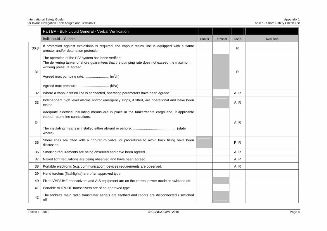
International Safety Guide Appendix 1 for Inland Navigation Tank-barges and Terminals Tanker – Shore Safety Check-List
Edition 1 - 2010 © CCNR/OCIMF 2010 Page 4
Part BA - Bulk Liquid General - Verbal Verification
Bulk Liquid – General Tanker Terminal Code Remarks
30.3 If protection against explosions is required, the vapour return line is equipped with a flame arrestor and/or detonation protection.
R
31
The operation of the P/V system has been verified. The delivering tanker or shore guarantees that the pumping rate does not exceed the maximum working pressure agreed. Agreed max pumping rate: ........................ (m3/h) Agreed max pressure: ............................... (kPa)
R
32 Where a vapour return line is connected, operating parameters have been agreed. A R
33 Independent high level alarms and/or emergency stops, if fitted, are operational and have been tested.
A R
34
Adequate electrical insulating means are in place in the tanker/shore cargo and, if applicable vapour return line connections.
The insulating means is installed either aboard or ashore: ........................................... (state where).
A R
35 Shore lines are fitted with a non-return valve, or procedures to avoid back filling have been discussed.
P R
36 Smoking requirements are being observed and have been agreed. A R
37 Naked light regulations are being observed and have been agreed. A R
38 Portable electronic (e.g. communication) devices requirements are observed. A R
39 Hand torches (flashlights) are of an approved type.
40 Fixed VHF/UHF transceivers and AIS equipment are on the correct power mode or switched off.
41 Portable VHF/UHF transceivers are of an approved type.
42 The tanker's main radio transmitter aerials are earthed and radars are disconnected / switched off.

International Safety Guide Appendix 1 for Inland Navigation Tank-barges and Terminals Tanker – Shore Safety Check-List
Edition 1 - 2010 © CCNR/OCIMF 2010 Page 5
Part BA - Bulk Liquid General - Verbal Verification
Bulk Liquid – General Tanker Terminal Code Remarks
43 Electric cables to portable electrical equipment within the hazardous area are disconnected from power.
44 Window type air conditioning units are disconnected, if applicable.
45 Positive pressure is maintained inside the accommodation and/or wheelhouse, if applicable.
46 Measures have been taken to ensure sufficient mechanical ventilation in the pumproom, if applicable.
R
47 There is provision for an emergency escape.
48
The weather conditions, maximum wind and swell criteria for operations have been agreed. Stop cargo operations at: ............................................................................................................ Disconnect at: ............................................................................................................................. Unmoor at: ..................................................................................................................................
A
49 Security protocols have been agreed between the Ship Security Officer and the Port Facility Security Officer, if appropriate.
A
50 Where appropriate, procedures have been agreed for receiving nitrogen supplied from shore, either for inerting or purging cargo tanks, or for line clearing into the tanker.
A P

International Safety Guide Appendix 1 for Inland Navigation Tank-barges and Terminals Tanker – Shore Safety Check-List
Edition 1 - 2010 © CCNR/OCIMF 2010 Page 6
If the tanker is fitted, or is required to be fitted, with an inert gas system (IGS), the following statements should be addressed:
Inert Gas System Tanker Terminal Code Remarks
51 The IGS is fully operational and in good working order. P
52 Deck seals, or equivalent, are in good working order. R
53 Liquid levels in pressure/vacuum breakers are correct, if applicable. R
54 The fixed and portable oxygen analysers have been calibrated and are working properly. R
55 All the individual tank IG valves (if fitted) are correctly set and locked. R
56 All personnel in charge of cargo operations are aware that, in the event of failure of the inert gas plant, discharge operations should cease and the terminal be advised.
If the tanker is fitted with a Crude Oil Washing (COW) system, and intends to crude oil wash, the following statements should be addressed:
Crude Oil Washing Tanker Terminal Code Remarks
57 N/A
58 N/A
If the tanker is planning to tank clean alongside, the following statements should be addressed:
Tank Cleaning Tanker Terminal Code Remarks
59 Tank cleaning operations are planned during the tanker's stay alongside the shore installation. Yes/No* Yes/No*
60 lf 'yes', the procedures and approvals for tank cleaning have been agreed.
61 Permission has been granted for gas freeing operations by the competent authority. Yes/No* Yes/No*
*Delete Yes or No as appropriate

International Safety Guide Appendix 1 for Inland Navigation Tank-barges and Terminals Tanker – Shore Safety Check-List
Edition 1 - 2010 © CCNR/OCIMF 2010 Page 7
Part 'C' Bulk Chemicals - Verbal Verification
Bulk Liquid Chemicals Tanker Terminal Code Remarks
1 Material Safety Data Sheets, or equivalent, are available giving the necessary data for the safe handling of the cargo.
2 A manufacturer's inhibition certificate, where applicable, has been provided. P
3 Sufficient protective clothing and equipment (including self-contained breathing apparatus) is ready for immediate use and is suitable for the product being handled.
4 Countermeasures in the event of accidental personal contact with the cargo have been agreed.
5 The cargo handling rate is compatible with the automatic shutdown system, if in use. A
6 Cargo system gauges and alarms are correctly set and in good order.
7 Portable vapour detection instruments are readily available for the products being handled.
8 lnformation on fire-fighting equipment and procedures has been exchanged.
9 Transfer hoses and gaskets are of suitable material, resistant to the action of the products being handled.
10 Cargo handling is being performed with the permanent installed pipeline system. P
11 Where appropriate, procedures have been agreed for receiving nitrogen supplied from shore, either for inerting or purging cargo tanks, or for line clearing into the tanker.
A P
12 If required, the cargo deck water spray system is ready for immediate use.
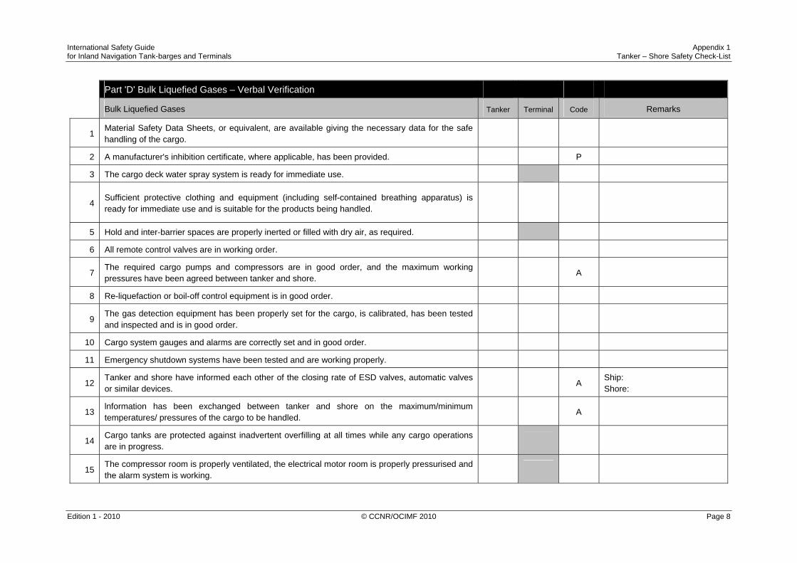
International Safety Guide Appendix 1 for Inland Navigation Tank-barges and Terminals Tanker – Shore Safety Check-List
Edition 1 - 2010 © CCNR/OCIMF 2010 Page 8
Part 'D' Bulk Liquefied Gases – Verbal Verification
Bulk Liquefied Gases Tanker Terminal Code Remarks
1 Material Safety Data Sheets, or equivalent, are available giving the necessary data for the safe handling of the cargo.
2 A manufacturer's inhibition certificate, where applicable, has been provided. P
3 The cargo deck water spray system is ready for immediate use.
4 Sufficient protective clothing and equipment (including self-contained breathing apparatus) is ready for immediate use and is suitable for the products being handled.
5 Hold and inter-barrier spaces are properly inerted or filled with dry air, as required.
6 All remote control valves are in working order.
7 The required cargo pumps and compressors are in good order, and the maximum working pressures have been agreed between tanker and shore.
A
8 Re-liquefaction or boil-off control equipment is in good order.
9 The gas detection equipment has been properly set for the cargo, is calibrated, has been tested and inspected and is in good order.
10 Cargo system gauges and alarms are correctly set and in good order.
11 Emergency shutdown systems have been tested and are working properly.
12 Tanker and shore have informed each other of the closing rate of ESD valves, automatic valves or similar devices.
A Ship: Shore:
13 lnformation has been exchanged between tanker and shore on the maximum/minimum temperatures/ pressures of the cargo to be handled.
A
14 Cargo tanks are protected against inadvertent overfilling at all times while any cargo operations are in progress.
15 The compressor room is properly ventilated, the electrical motor room is properly pressurised and the alarm system is working.
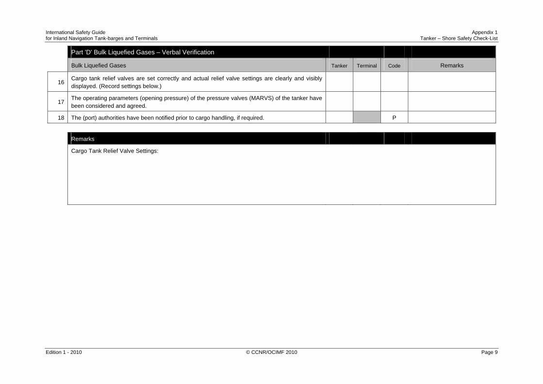
International Safety Guide Appendix 1 for Inland Navigation Tank-barges and Terminals Tanker – Shore Safety Check-List
Edition 1 - 2010 © CCNR/OCIMF 2010 Page 9
Part 'D' Bulk Liquefied Gases – Verbal Verification
Bulk Liquefied Gases Tanker Terminal Code Remarks
16 Cargo tank relief valves are set correctly and actual relief valve settings are clearly and visibly displayed. (Record settings below.)
17 The operating parameters (opening pressure) of the pressure valves (MARVS) of the tanker have been considered and agreed.
18 The (port) authorities have been notified prior to cargo handling, if required. P
Remarks
Cargo Tank Relief Valve Settings:

International Safety Guide Appendix 1 for Inland Navigation Tank-barges and Terminals Tanker – Shore Safety Check-List
Edition 1 - 2010 © CCNR/OCIMF 2010 Page 10

International Safety Guide Appendix 1 for Inland Navigation Tank-barges and Terminals Tanker – Shore Safety Check-List
Edition 1 - 2010 © CCNR/OCIMF 2010 Page 11
DECLARATION
We, the undersigned, have checked the above items in Parts A and B and, where appropriate, Part C or D, in accordance with the instructions and have satisfied ourselves that the entries we have made are correct. We have also made arrangements to carry out repetitive checks as necessary and agreed that those items coded ‘R’ in the Checklist should be re-checked at intervals not exceeding ……………. hours. If, to our knowledge, the status of any item changes, we will immediately inform the other party.
For Inland tanker For Shore
Name: ...................................................................... Name: ......................................................................
Rank: ....................................................................... Position or Title: .......................................................
Signature: ................................................................ Signature: ................................................................
Date: ........................................................................ Date: ........................................................................
Time: ....................................................................... Time: ....................................................................... Record of repetitive checks:
Date:
Time:
Initials for tanker:
Initials for shore:

International Safety Guide Appendix 1 for Inland Navigation Tank-barges and Terminals Tanker – Shore Safety Check-List
Edition 1 - 2010 © CCNR/OCIMF 2010 Page 12

International Safety Guide Appendix 2 for Inland Navigation Tank-barges and Terminals Seagoing – Inland Tanker / Inland Tanker Safety Check-List
Edition 1 - 2010 © CCNR/OCIMF 2010 Page 1
SEAGOING* – INLAND* TANKER / INLAND TANKER SAFETY CHECK-LIST
Name of Seagoing* / Inland* Tanker 1:................................................................................................... Date of Arrival: ................................................. Time of Arrival: ...................................................... Name of Inland Tanker 2: ........................................................................................................................ Date of Arrival: ................................................. Time of Arrival: ...................................................... Location: ............................................................................. Port: ...................................................... * delete where not applicable

International Safety Guide Appendix 2 for Inland Navigation Tank-barges and Terminals Seagoing – Inland Tanker / Inland Tanker Safety Check-List
Edition 1 - 2010 © CCNR/OCIMF 2010 Page 2

International Safety Guide Appendix 2 for Inland Navigation Tank-barges and Terminals Seagoing – Inland Tanker / Inland Tanker Safety Check-List
Edition 1 - 2010 © CCNR/OCIMF 2010 Page 3
Part A - Bulk Liquid General - Physical Checks
REGIONAL LEGISLATION
Bulk Liquid – General SEAGOING TANKER
INLAND TANKER 1
INLAND TANKER 2
Code Remarks
1 There is safe access between the (seagoing) tanker and inland tanker.
R
L L1 The fendering arrangements are assessed as being satisfactory. The fender pennants are in order.
R
B 3 2 The tanker is securely moored, considering the conditions locally. R
B 11 3 The agreed inter-ship communication system is operative. A R VHF Channel: Communication system: Back up system:
L 4 Emergency towing-off pennants are correctly rigged and positioned, if required by terminal.
R
B 14 5 The tanker’s fire hoses and fire-fighting equipment are positioned and ready for immediate use.
R
B 6.1 7 The tanker's cargo hoses, pipelines and manifolds are in good condition, properly rigged and appropriate for the service intended.
R
B 6.1 7.1 All reducers are approved and compatible with cargo lines and the type of cargo.
B 6.2 7.2 All connection flanges are fitted with the appropriate gaskets.
B 6.3 7.3 All flange bolts are properly tightened.
B 6.4 7.4 The hoses have enough room for easy movement.
B 14 7.5 All valves are checked and in the right position.
B 5 7.6 Adequate lighting is ensured at the cargo transfer area and emergency escape route.
8 This line has been intentionally left blank.

International Safety Guide Appendix 2 for Inland Navigation Tank-barges and Terminals Seagoing – Inland Tanker / Inland Tanker Safety Check-List
Edition 1 - 2010 © CCNR/OCIMF 2010 Page 4
Part A - Bulk Liquid General - Physical Checks
REGIONAL LEGISLATION
Bulk Liquid – General SEAGOING TANKER
INLAND TANKER 1
INLAND TANKER 2
Code Remarks
L 9 The cargo transfer system is sufficiently isolated and drained to allow safe removal of blank flanges prior to connection.
B 8 10 Scuppers and ‘save alls’ on board are effectively plugged and drip trays are in position and empty.
R
L 11 Scupper plugs temporarily removed will be monitored constantly. R
12 This line has been intentionally left blank.
B 7 13 The tanker’s unused cargo and bunker/vapour return connections are properly secured.
14 This line has been intentionally left blank.
B 18 15 If required, all sighting, ullaging and sampling ports of the cargo, ballast or bunker tanks have been closed or protected by flame arrestors in good condition.
B 9 16 Sea and overboard discharge valves, when not in use, are closed and visibly secured. The removable parts between ballast and overboard discharge lines and cargo lines are removed.
B 14 17.1 All external doors, ports and windows in the accommodation, stores and machinery spaces are closed. Engine room vents may be open.
R
17.2 The LPG domestic installation is isolated at the main stop valve.
L 18 The tanker’s emergency fire control plans are available. Locations:

International Safety Guide Appendix 2 for Inland Navigation Tank-barges and Terminals Seagoing – Inland Tanker / Inland Tanker Safety Check-List
Edition 1 - 2010 © CCNR/OCIMF 2010 Page 5
If the tanker(s) is fitted, or is required to be fitted, with an inert gas system (IGS), the following points should be physically checked:
REGIONAL LEGISLATION
Inert Gas System SEAGOING TANKER
INLAND TANKER 1
INLAND TANKER 2
Code Remarks
L 19 IGS pressure and oxygen content measuring equipment recorders are in good working order.
R
L 20 All cargo tank atmospheres are at positive pressure with oxygen content of 8% or less by volume.
P R
L 20L All inerted tanks are marked or labelled with a warning sign. Part B - Bulk Liquid General - Verbal Verification
REGIONAL LEGISLATION
Bulk Liquid – General SEAGOING TANKER
INLAND TANKER 1
INLAND TANKER 2
Code Remarks
L 21 The tankers are ready to move under their own power. A dumb barge without own propulsion means should be able to move with the help of a designated tug at short notice.
P R
B 10 22 There is an effective deck watch in attendance on board and adequate supervision of operations on both tankers.
R
L 22L On each tanker a competent person is appointed who is responsible for the planned cargo handling.
L 23 There are sufficient personnel on board both tankers to deal with an emergency.
R
B 15.1 24.1 The procedures for cargo, bunker and ballast handling have been agreed.
A R

International Safety Guide Appendix 2 for Inland Navigation Tank-barges and Terminals Seagoing – Inland Tanker / Inland Tanker Safety Check-List
Edition 1 - 2010 © CCNR/OCIMF 2010 Page 6
Part B - Bulk Liquid General - Verbal Verification
REGIONAL LEGISLATION
Bulk Liquid – General SEAGOING TANKER
INLAND TANKER 1
INLAND TANKER 2
Code Remarks
B 15.2 24.2 The outlet pressure of the cargo pump of the other tanker is regulated to take account of the admissible working pressure of the equipment on board the tanker.
A R
B 13 25 The emergency signal and shutdown procedures to be used by both tankers have been explained and understood.
A
B 2 26 Material Safety Data Sheets (MSDS), or equivalent, for the cargo transfer have been exchanged where requested.
P + R
B1 26L The tanker is approved to transport the product to be loaded.
L 27 The hazards associated with toxic substances in the cargo being handled have been identified and understood.
H2S content: Benzene content:
28 An International Shore Fire Connection has been provided.
L 29 The agreed tank venting system will be used. A R Method:
30.1 The requirements for closed operations have been agreed. R
B 12.1 30.2 The tanker’s vapour return connection, if required, is connected, by means of a vapour return line, to the vapour return connection of the other tanker.
R
B 12.3 30.3 If protection against explosions is required, the vapour return line is equipped with a flame arrestor and/or detonation protection.
R
B 12.2 31 The operation of the P/V system has been verified.The delivering tanker guarantees that the pumping rate does not exceed the maximum working pressure agreed.
R
Agreed max pumping rate: ................. (m3/h) Agreed max pressure: ......................... (kPa)
L 32 Where a vapour return line is connected, operating parameters have been agreed.
A R
B 16+17 33 Independent high level alarms and/or emergency stops, if fitted, are operational and have been tested.
A R

International Safety Guide Appendix 2 for Inland Navigation Tank-barges and Terminals Seagoing – Inland Tanker / Inland Tanker Safety Check-List
Edition 1 - 2010 © CCNR/OCIMF 2010 Page 7
Part B - Bulk Liquid General - Verbal Verification
REGIONAL LEGISLATION
Bulk Liquid – General SEAGOING TANKER
INLAND TANKER 1
INLAND TANKER 2
Code Remarks
L 34
Adequate electrical insulating means are in place in the tanker/tanker cargo and vapour return (if applicable) line connections. The insulating means is installed only on board ............................. (name tanker).
A R
35 This line has been intentionally left blank.
B 14 36 Smoking requirements are being observed and have been agreed. A R
B 14 37 Naked light regulations are being observed and have been agreed. A R
L 38 Portable electronic (e.g. communication) device requirements are observed.
A R
L 39 Hand torches (flashlights) are of an approved type.
L 40 Fixed VHF/UHF transceivers and AIS equipment are on the correct power mode or switched off.
L 41 Portable VHF/UHF transceivers are of an approved type.
B 14 42 The tankers’ main radio transmitter aerials are earthed and radars are disconnected / switched off.
B 14 43 Electric cables to portable electrical equipment within the hazardous area are disconnected from power.
L 44 Window type air conditioning units are disconnected, if applicable.
L 45 Positive pressure is maintained inside the accommodation and/or wheelhouse, if applicable.
L 46 Measures have been taken to ensure sufficient mechanical ventilation in the pumproom, if applicable.
R
B 4 47 There is provision for an emergency escape or for emergency boarding positioned ready for use.

International Safety Guide Appendix 2 for Inland Navigation Tank-barges and Terminals Seagoing – Inland Tanker / Inland Tanker Safety Check-List
Edition 1 - 2010 © CCNR/OCIMF 2010 Page 8
Part B - Bulk Liquid General - Verbal Verification
REGIONAL LEGISLATION
Bulk Liquid – General SEAGOING TANKER
INLAND TANKER 1
INLAND TANKER 2
Code Remarks
L 48
The weather conditions, maximum wind and swell criteria for operations have been agreed.
Stop cargo operations at: ................................................................. Disconnect at: .................................................................................. Unmoor at: .......................................................................................
A
L 49 Security protocols have been agreed between the tankers’ Security Responsible Persons / Officers, if appropriate.
A
L 49L
Security protocols have been agreed for the crew of one tanker to board the other tanker.
The location of the security protocol for boarding tanker is: ……………………..
L 50 Where appropriate, procedures have been agreed for receiving nitrogen, either for inerting or purging tanker’s tanks, or for line clearing.
A P

International Safety Guide Appendix 2 for Inland Navigation Tank-barges and Terminals Seagoing – Inland Tanker / Inland Tanker Safety Check-List
Edition 1 - 2010 © CCNR/OCIMF 2010 Page 9
Part B - Bulk Liquid General - Verbal Verification
If the tanker(s) is fitted, or is required to be fitted, with an inert gas system (IGS), the following statements should be addressed:
REGIONAL LEGISLATION
Inert Gas System SEAGOING TANKER
INLAND TANKER 1
INLAND TANKER 2
Code Remarks
L 51 The IGS is fully operational and in good working order, if applicable. P
L 52 Deck seals, or equivalent, are in good working order, if applicable. R
L 53 Liquid levels in pressure/vacuum breakers are correct, if applicable. R
L 54 The fixed and portable oxygen analysers have been calibrated and are working properly.
R
L 55 All the individual tank IGS valves (if fitted) are correctly set and locked.
R
L 56 All personnel in charge of cargo operations are aware that, in the event of failure of the inert gas plant, discharge operations should cease, and the other tanker should be advised.
If the tanker is fitted with a Crude Oil Washing (COW) system, and intends to crude oil wash, the following statements should be addressed:
REGIONAL LEGISLATION
Crude Oil Washing SEAGOING TANKER
INLAND TANKER 1
INLAND TANKER 2
Code Remarks
L 57 N/A
L 58 N/A

International Safety Guide Appendix 2 for Inland Navigation Tank-barges and Terminals Seagoing – Inland Tanker / Inland Tanker Safety Check-List
Edition 1 - 2010 © CCNR/OCIMF 2010 Page 10
Part B - Bulk Liquid General - Verbal Verification
If the tanker is planning to tank clean alongside, the following statements should be addressed:
REGIONAL LEGISLATION
Tank Cleaning SEAGOING TANKER
INLAND TANKER 1
INLAND TANKER 2
Code Remarks
L 59 Tank cleaning operations are planned during the tanker’s stay alongside the other tanker.
YES NO*
YES NO*
YES NO*
L 60 If ‘yes’ the procedures and approvals for tank cleaning have been agreed.
L 61 Permission has been granted for gas-freeing operations by the competent authority.
YES NO*
YES NO*
YES NO*
*Delete Yes or No as appropriate Part 'C' Bulk Chemicals - Verbal Verification
REGIONAL LEGISLATION
Bulk Liquid Chemicals SEAGOING TANKER
INLAND TANKER 1
INLAND TANKER 2
Code Remarks
L 1 Material Safety Data Sheets, or equivalent, are available giving the necessary data for the safe handling of the cargo.
L 2 A manufacturer’s inhibition certificate, where applicable, has been provided.
P
L 3 Sufficient protective clothing and equipment (including self-contained breathing apparatus) is ready for immediate use and is suitable for the product being handled, if applicable.
L 4 Countermeasures in the event of accidental personal contact with the cargo have been agreed.
L 5 The cargo handling rate is compatible with the automatic shutdown system, if in use.
A

International Safety Guide Appendix 2 for Inland Navigation Tank-barges and Terminals Seagoing – Inland Tanker / Inland Tanker Safety Check-List
Edition 1 - 2010 © CCNR/OCIMF 2010 Page 11
Part 'C' Bulk Chemicals - Verbal Verification
REGIONAL LEGISLATION
Bulk Liquid Chemicals SEAGOING TANKER
INLAND TANKER 1
INLAND TANKER 2
Code Remarks
L 6 Cargo system gauges and alarms are correctly set and in good order.
L 7 Portable vapour detection instruments are readily available for the products being handled.
L 8 Information on fire-fighting equipment and procedures has been exchanged.
L 9 Transfer hoses and gaskets are of suitable material, resistant to the action of the products being handled.
L 10 Cargo handling is being performed with the permanent installed pipeline system.
P
11 This line has been intentionally left blank.
L 12 If required, the cargo deck water spray system is ready for immediate use.
Part 'D' Bulk Liquefied Gases - Verbal Verification
REGIONAL LEGISLATION
Bulk Liquefied Gases SEAGOING TANKER
INLAND TANKER 1
INLAND TANKER 2
Code Remarks
L 1 Material Safety Data Sheets, or equivalent, are available giving the necessary data for the safe handling of the cargo.
L 2 A manufacturer’s inhibition certificate, where applicable, has been provided.
P
L 3 The cargo deck water spray system is ready for immediate use.
L 4 Sufficient protective clothing and equipment (including self-contained breathing apparatus) is ready for immediate use and is suitable for the products being handled, if applicable.
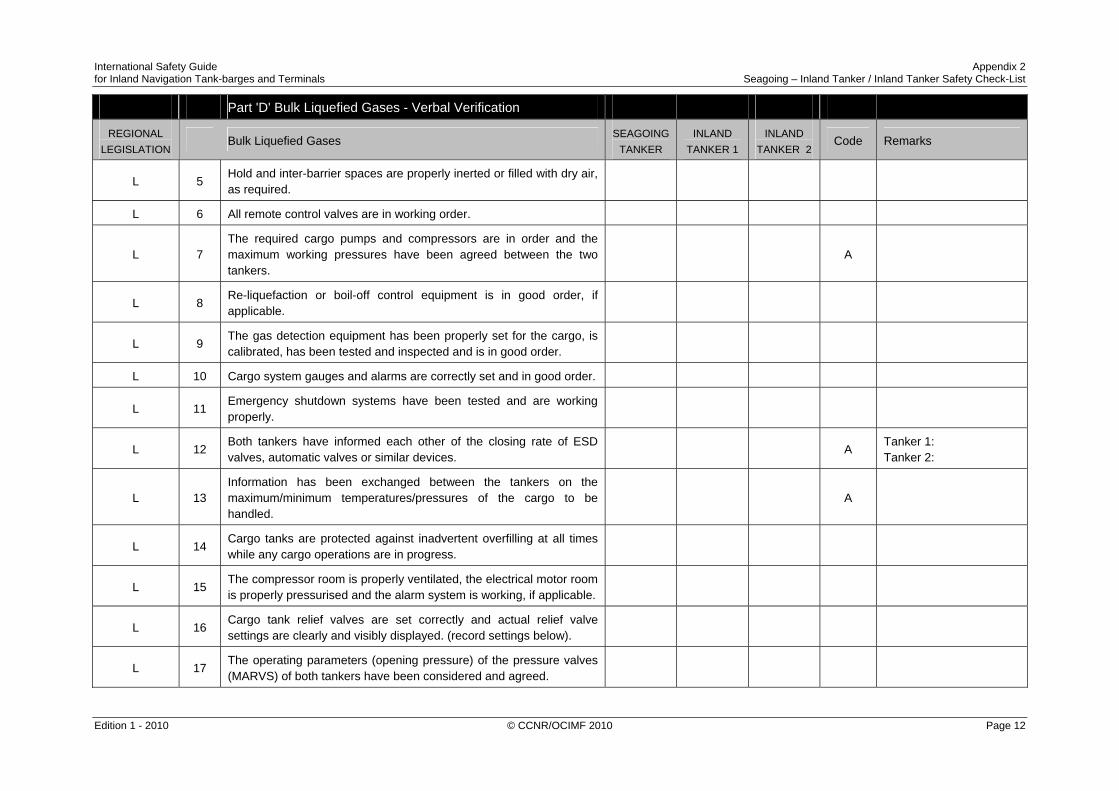
International Safety Guide Appendix 2 for Inland Navigation Tank-barges and Terminals Seagoing – Inland Tanker / Inland Tanker Safety Check-List
Edition 1 - 2010 © CCNR/OCIMF 2010 Page 12
Part 'D' Bulk Liquefied Gases - Verbal Verification
REGIONAL LEGISLATION
Bulk Liquefied Gases SEAGOING TANKER
INLAND TANKER 1
INLAND TANKER 2
Code Remarks
L 5 Hold and inter-barrier spaces are properly inerted or filled with dry air, as required.
L 6 All remote control valves are in working order.
L 7 The required cargo pumps and compressors are in order and the maximum working pressures have been agreed between the two tankers.
A
L 8 Re-liquefaction or boil-off control equipment is in good order, if applicable.
L 9 The gas detection equipment has been properly set for the cargo, is calibrated, has been tested and inspected and is in good order.
L 10 Cargo system gauges and alarms are correctly set and in good order.
L 11 Emergency shutdown systems have been tested and are working properly.
L 12 Both tankers have informed each other of the closing rate of ESD valves, automatic valves or similar devices.
A Tanker 1: Tanker 2:
L 13 Information has been exchanged between the tankers on the maximum/minimum temperatures/pressures of the cargo to be handled.
A
L 14 Cargo tanks are protected against inadvertent overfilling at all times while any cargo operations are in progress.
L 15 The compressor room is properly ventilated, the electrical motor room is properly pressurised and the alarm system is working, if applicable.
L 16 Cargo tank relief valves are set correctly and actual relief valve settings are clearly and visibly displayed. (record settings below).
L 17 The operating parameters (opening pressure) of the pressure valves (MARVS) of both tankers have been considered and agreed.

International Safety Guide Appendix 2 for Inland Navigation Tank-barges and Terminals Seagoing – Inland Tanker / Inland Tanker Safety Check-List
Edition 1 - 2010 © CCNR/OCIMF 2010 Page 13
Part 'D' Bulk Liquefied Gases - Verbal Verification
REGIONAL LEGISLATION
Bulk Liquefied Gases SEAGOING TANKER
INLAND TANKER 1
INLAND TANKER 2
Code Remarks
L 18 The (port) authorities have been notified prior to cargo handling, if required.
P
L 19 If required by the (port) authorities, an external co-ordinator has been appointed and is on board as co-ordinator responsible for the planned cargo handling between the two tankers.
P Name of external co-ordinator: Company:
Remarks
Pressure Relief Valve Settings:

International Safety Guide Appendix 2 for Inland Navigation Tank-barges and Terminals Seagoing – Inland Tanker / Inland Tanker Safety Check-List
Edition 1 - 2010 © CCNR/OCIMF 2010 Page 14

International Safety Guide Appendix 2 for Inland Navigation Tank-barges and Terminals Seagoing – Inland Tanker / Inland Tanker Safety Check-List
Edition 1 - 2010 © CCNR/OCIMF 2010 Page 15
OPERATIONAL ARRANGEMENTS
Seagoing* / Inland* Tanker 1: ............................................................................. Inland Tanker 2: .............................................................................. Date: ..................................................... Time: ................................................ Location: .......................................................................................... The following cargo or ballasting operations will be carried out at the above-mentioned location:
Stop by: Seagoing* / Inland* Tanker 1 Inland Tanker 2
Pro
duct
Qua
ntity
(m3 )
Act
ual t
empe
ratu
re (°
C)
Sta
rting
tim
e
Com
plet
ion
time
Seag
oing
* / i
nlan
d*
tank
er 1
Inla
nd ta
nker
2
Tank
Tank
cap
acity
Man
ifold
con
nect
ion
Max
load
/unl
oad
rate
Max
pre
ssur
e
Load
ing*
/ un
load
ing*
Tank
Tank
cap
acity
Line
Max
rate
Max
pre
ssur
e
Responsible Officer Seagoing* / Inland* Tanker 1: Responsible officer Inland Tanker 2: ........................................................................................... ........................................................................................... * delete where not applicable

International Safety Guide Appendix 2 for Inland Navigation Tank-barges and Terminals Seagoing – Inland Tanker / Inland Tanker Safety Check-List
Edition 1 - 2010 © CCNR/OCIMF 2010 Page 16

International Safety Guide Appendix 2 for Inland Navigation Tank-barges and Terminals Seagoing – Inland Tanker / Inland Tanker Safety Check-List
Edition 1 - 2010 © CCNR/OCIMF 2010 Page 17
DECLARATION
We, the undersigned, have checked the above items in Parts A and B and, where appropriate, Part C or D, in accordance with the instructions and have satisfied ourselves that the entries we have made are correct. We have also made arrangements to carry out repetitive checks as necessary and agreed that those items coded ‘R’ in the Checklist should be re-checked at intervals not exceeding ……………. hours. If, to our knowledge, the status of any item changes, we will immediately inform the other party.
For the Seagoing* / Inland* Tanker 1 For the Inland Tanker 2
Name: ...................................................................... Name: ......................................................................
Rank: ....................................................................... Rank: ........................................................................
Signature: ................................................................ Signature: ................................................................
Date: ........................................................................ Date: ........................................................................
Time: ....................................................................... Time: ....................................................................... Record of repetitive checks:
Date:
Time:
Initials for the Seagoing* / Inland* Tanker 1:
Initials for the Inland Tanker 2:
* delete where not applicable

International Safety Guide Appendix 2 for Inland Navigation Tank-barges and Terminals Seagoing – Inland Tanker / Inland Tanker Safety Check-List
Edition 1 - 2010 © CCNR/OCIMF 2010 Page 18

International Safety Guide Appendix 3 for Inland Navigation Tank-barges and Terminals Hazardous Disposal Safety Check-List
Edition 1 - 2010 © CCNR/OCIMF 2010 Page 1
HAZARDOUS DISPOSAL SAFETY CHECK-LIST
Name of Seagoing Vessel: ........................................................................................................................ Name of Tanker: ........................................................................................................................................ Name of Receiving Terminal: .................................................................................................................... Port: ........................................................................................................................................................... Berth: ....................................................................... Date of disposal: ........................................................................................................................................ Time of arrival of tanker: .........................................
Disposal of: Quantity (m³) UN number Hazardous components Class Legal waste code Remarks
BILGE WATER
ENGINE ROOM SLUDGE
WASHING WATERS / SLOPS
DIRTY BALLAST
OTHERS
Operational arrangements
Liquid waste: Tank N° tanker
Tank N° terminal Available tank capacity (m³) Max pumping rate
in m³/h Max. pressure (kPa) Remarks
BILGE WATER
ENGINE ROOM SLUDGE
WASHING WATERS / SLOPS
DIRTY BALLAST
OTHERS
To be used in combination with either Appendix 1 Tanker - Shore Safety Check-List or Appendix 2 Seagoing – Inland Tanker / Inland Tanker Safety Check-List

International Safety Guide Appendix 3 for Inland Navigation Tank-barges and Terminals Hazardous Disposal Safety Check-List
Edition 1 - 2010 © CCNR/OCIMF 2010 Page 2

International Safety Guide Appendix 4 for Inland Navigation Tank-barges and Terminals Non hazardous Disposal Safety Check-List
Edition 1 - 2010 © CCNR/OCIMF 2010 Page 1
NON HAZARDOUS DISPOSAL SAFETY CHECK-LIST
Name of Seagoing Vessel: ........................................................................................................................ Name Tanker: ............................................................................................................................................ Name of Receiving Terminal: .................................................................................................................... Port: ........................................................................................................................................................... Berth: ....................................................................... Date of disposal: ........................................................................................................................................ Time of arrival of tanker: .........................................
Disposal of: Quantity (m³) Specification Legal code Remarks
BILGE WATER
ENGINE ROOM SLUDGE
WASHING WATERS / SLOPS
DIRTY BALLAST
OTHERS
Operational arrangements
Liquid waste: Tank N° tanker Tank N° terminal Available tank capacity (m³) Max pumping
rate in m³/h Max. pressure (kPa) Remarks
BILGE WATER
ENGINE ROOM SLUDGE
WASHING WATERS / SLOPS
DIRTY BALLAST
OTHERS
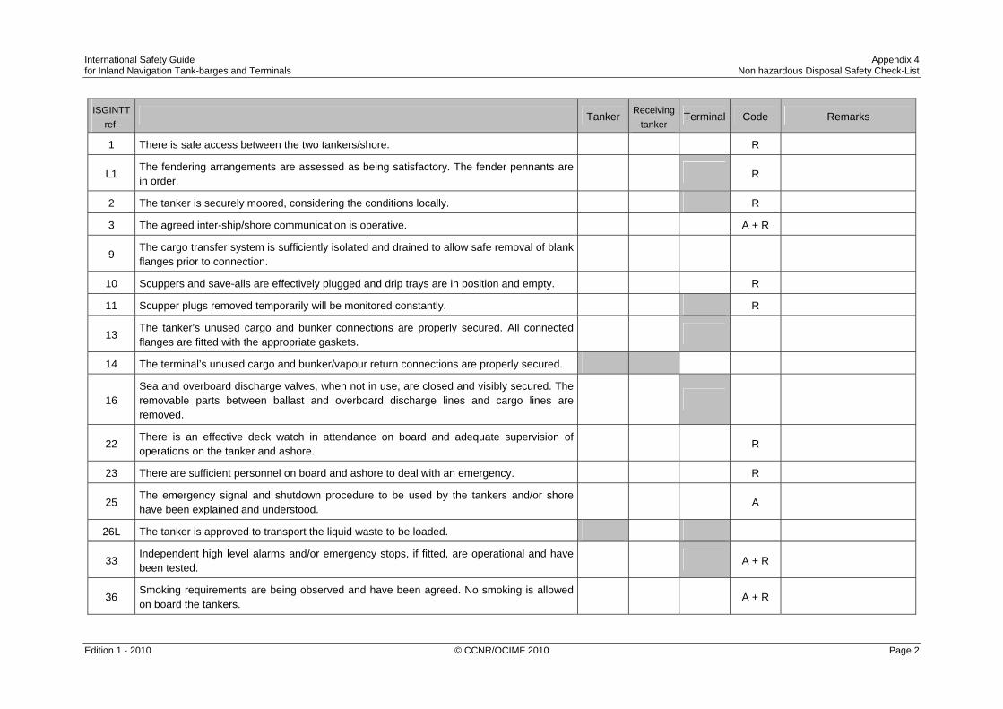
International Safety Guide Appendix 4 for Inland Navigation Tank-barges and Terminals Non hazardous Disposal Safety Check-List
Edition 1 - 2010 © CCNR/OCIMF 2010 Page 2
ISGINTT
ref. Tanker Receiving
tanker Terminal Code Remarks
1 There is safe access between the two tankers/shore. R
L1 The fendering arrangements are assessed as being satisfactory. The fender pennants are in order.
R
2 The tanker is securely moored, considering the conditions locally. R
3 The agreed inter-ship/shore communication is operative. A + R
9 The cargo transfer system is sufficiently isolated and drained to allow safe removal of blank flanges prior to connection.
10 Scuppers and save-alls are effectively plugged and drip trays are in position and empty. R
11 Scupper plugs removed temporarily will be monitored constantly. R
13 The tanker’s unused cargo and bunker connections are properly secured. All connected flanges are fitted with the appropriate gaskets.
14 The terminal’s unused cargo and bunker/vapour return connections are properly secured.
16 Sea and overboard discharge valves, when not in use, are closed and visibly secured. The removable parts between ballast and overboard discharge lines and cargo lines are removed.
22 There is an effective deck watch in attendance on board and adequate supervision of operations on the tanker and ashore.
R
23 There are sufficient personnel on board and ashore to deal with an emergency. R
25 The emergency signal and shutdown procedure to be used by the tankers and/or shore have been explained and understood.
A
26L The tanker is approved to transport the liquid waste to be loaded.
33 Independent high level alarms and/or emergency stops, if fitted, are operational and have been tested.
A + R
36 Smoking requirements are being observed and have been agreed. No smoking is allowed on board the tankers.
A + R

International Safety Guide Appendix 4 for Inland Navigation Tank-barges and Terminals Non hazardous Disposal Safety Check-List
Edition 1 - 2010 © CCNR/OCIMF 2010 Page 3
ISGINTT ref.
Tanker Receiving tanker
Terminal Code Remarks
48
The weather conditions, maximum wind and swell criteria for operations have been agreed. Stop cargo operations at: ................................................................................................. Disconnect at: ................................................................................................................... Unmoor at: ........................................................................................................................
A
59 Tank cleaning operations are planned during the tanker's stay alongside the shore installation.
Yes / No Yes / No Yes / No
60 lf 'yes', the procedures and approvals for tank cleaning have been agreed.
C 9 Transfer hoses and gaskets are of suitable material, resistant to the liquid waste being handled and properly rigged.
legal The procedures for the disposal have been agreed and in line with local legislation.
Checked, filled in and signed For the seagoing tanker / tanker
Checked, filled in and signed For the tanker / terminal
Name: ............................................................................................................... Name: ...............................................................................................................
Rank: ................................................................................................................ Rank: ................................................................................................................
Signature: ......................................................................................................... Signature: .........................................................................................................
Date: ................................................................................................................. Date: .................................................................................................................
Time: ................................................................................................................ Time: ................................................................................................................

International Safety Guide Appendix 4 for Inland Navigation Tank-barges and Terminals Non hazardous Disposal Safety Check-List
Edition 1 - 2010 © CCNR/OCIMF 2010 Page 4

International Safety Guide Appendix 5 for Inland Navigation Tank-barges and Terminals Bunkering Safety Check-List for Bunker Delivery to Inland Ships
Edition 1 - 2010 © CCNR/OCIMF 2010 Page 1
BUNKERING SAFETY CHECK-LIST
FOR BUNKER DELIVERY TO INLAND SHIPS
Port / Navigation at (*) Date Time connected Time start pumping
Time disconnected Time stop pumping
< aft ship fore ship >
Yes No 1 (*) Is the receiving ship securely moored and sufficient fendering in place?
2 (*) Is the delivering ship securely moored and sufficient fendering in place?
3 (*) If bunkering during navigation has a safe sailing speed been agreed?
4 Are all of the bunker hoses in good condition and appropriate for the service intended?
5 Have effective communications been established between both parties?
6 Is there an effective watch on both ships?
7 Is enough lighting in place to monitor the delivery?
8 Are the smoking and open fire restrictions being observed?
9 Has an emergency stop procedure been agreed?
10 (**) Will a bunker overfill protection system be used?
11 (*) Has the filler pipe been connected properly and checked for tightness?
12 (*) If using a nozzle that cannot be fully connected, is the nozzle inserted far enough into the filling pipe opening and is the hose securely fastened to the receiving ship?
13 Are the bunker hoses rigged within their limits of torsion and pulling and is the radius of bending of the hoses above their minimum?
14 (*) Are spill containment arrangements in place? (Driptray, scupper plugs, spillrail, ...)
15 Is clean-up equipment available? Ticking or initialing the appropriate boxes and signing this Bunkering Safety Check-List for Bunker Delivery to Inland Ships confirms the acceptance of obligations.
Receiving ship Delivering bunker jetty / station / ship / truck (*)
Master's name Representative name
Signature Signature
(*) = delete where not applicable (**) = mandatory when available L = litres In general: bunkering may only take place if the questions 4 to 9, 13 and 15 are answered with ‘yes’
Number bunker tank 1 2 3 4 5 Grade
Tank capacity (@ 97%) L L L L L Content of tank before bunkering - L - L - L - L - L Capacity available for bunkering L L L L L
Agreed bunker quantity L L L L L Start pumping rate in: L /min | m3/h | tons/h (*)
Max pumping rate in: L /min | m3/h | tons/h (*)
Name of responsible during receiving operations Name of responsible during delivering operations Bunker tank contents are checked during operations at intervals of : Every ................ minutes

International Safety Guide Appendix 5 for Inland Navigation Tank-barges and Terminals Bunkering Safety Check-List for Bunker Delivery to Inland Ships
Edition 1 - 2010 © CCNR/OCIMF 2010 Page 2

International Safety Guide Appendix 6 for Inland Navigation Tank-barges and Terminals Bunkering Safety Check-List for Bunker Delivery to Maritime Ships
Edition 1 - 2010 © CCNR/OCIMF 2010 Page 1
BUNKERING SAFETY CHECK-LIST
FOR BUNKER DELIVERY TO MARITIME SHIPS (Chapter 25.4.3 ISGOTT)
Port: .............................................................. Date: ........................................................................... Ship: .............................................................. Barge: ......................................................................... Master: .......................................................... Master: ....................................................................... 1. Bunkers to be Transferred
Grade Tonnes Volume at
Loading Temp Loading
Temperature Maximum
Transfer Rate Maximum Line
Pressure
Fuel Oil
Gas Oil/Diesel
Lub. Oil in Bulk
2. Bunker Tanks to be Loaded
Tank No
Grade Volume of Tank @ ____ %
Vol. of Oil in Tank before
Loading
Available volume
Volume to be Loaded
Total Volumes Grade
3. Checks by Barge Prior to Berthing
Bunkering Ship Barge Code Remarks
1. The barge has obtained the necessary permissions to go alongside receiving ship.
2. The fenders have been checked, are in good order and there is no possibility of metal to metal contact.
R
3. Adequate electrical insulating means are in place in the barge-to-ship connection. (34)
4. All bunker hoses are in good condition and are appropriate for the service intended. (7)

International Safety Guide Appendix 6 for Inland Navigation Tank-barges and Terminals Bunkering Safety Check-List for Bunker Delivery to Maritime Ships
Edition 1 - 2010 © CCNR/OCIMF 2010 Page 2
4. Checks Prior to Transfer (cont.)
Bunkering Ship Barge Code Remarks
5. The barge is securely moored. (2)
6. There is a safe means of access between the ship and barge. (1)
7. Effective communications have been established between Respon-sible Officers. (3)
A R
(VHF/UHF Ch ... .). Primary System: Backup System: Emergency Stop Signal:
8. There is an effective watch on board the barge and on the ship receiving bunkers. (22)
9. Fire hoses and fire-fighting equip-ment on board the barge and ship are ready for immediate use. (5)
10. All scuppers are effectively plugged. Temporarily removed scupper plugs will be monitored at all times. Drip trays are in position on decks around connections and bunker tank vents. (10) (11)
R
11. Initial line up has been checked and unused bunker connections are blanked and fully bolted. (13)
12. The transfer hose is properly rigged and fully bolted and secured to manifolds on ship and barge. (7)
13. Overboard valves connected to the cargo system, engine room bilges and bunker lines are closed and sealed. (16)
14. All cargo and bunker tank hatch lids are closed. (15)
15. Bunker tank contents will be monitored at regular intervals. A R
at intervals not exceeding ……. Minutes
16. There is a supply of oil spill clean-up material readily available for immediate use.
17. The main radio transmitter aerials are earthed and radars are switched off. (42)
18. Fixed VHF/UHF transceivers and AIS equipment are on the correct power mode or switched off. (40)

International Safety Guide Appendix 6 for Inland Navigation Tank-barges and Terminals Bunkering Safety Check-List for Bunker Delivery to Maritime Ships
Edition 1 - 2010 © CCNR/OCIMF 2010 Page 3
Bunkering Ship Barge Code Remarks
19. Smoking rooms have been identified and smoking restrictions are being observed. (36)
A R Nominated Smoking RoomsTanker: Barge:
20. Naked light regulations are being observed. (37)
R
21. All external doors and ports in the accommodation are closed. (17)
R
22. Material Safety Data Sheets (MSDS) for the bunker transfer have been exchanged where requested. (26)
R
23. The hazards associated with toxic substances in the bunkers being handled have been identified and understood. (27)
R H2S Content ... Benzene Content ...

International Safety Guide Appendix 6 for Inland Navigation Tank-barges and Terminals Bunkering Safety Check-List for Bunker Delivery to Maritime Ships
Edition 1 - 2010 © CCNR/OCIMF 2010 Page 4
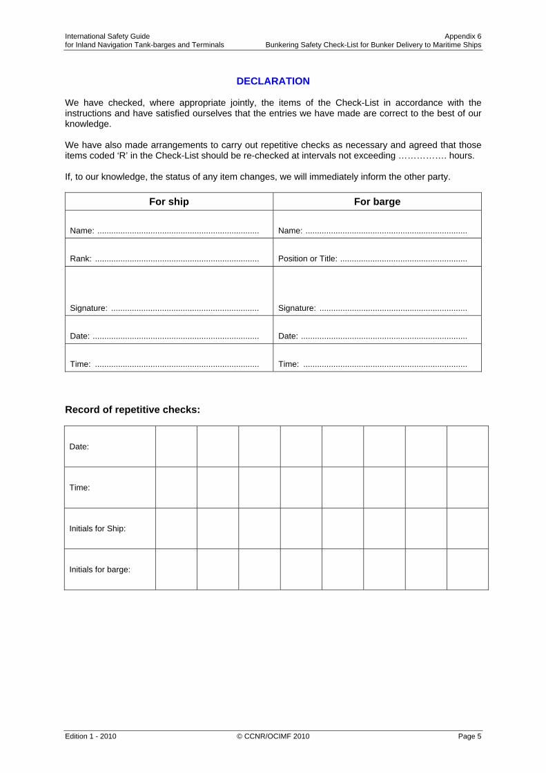
International Safety Guide Appendix 6 for Inland Navigation Tank-barges and Terminals Bunkering Safety Check-List for Bunker Delivery to Maritime Ships
Edition 1 - 2010 © CCNR/OCIMF 2010 Page 5
DECLARATION
We have checked, where appropriate jointly, the items of the Check-List in accordance with the instructions and have satisfied ourselves that the entries we have made are correct to the best of our knowledge. We have also made arrangements to carry out repetitive checks as necessary and agreed that those items coded ‘R’ in the Check-List should be re-checked at intervals not exceeding ……………. hours. If, to our knowledge, the status of any item changes, we will immediately inform the other party.
For ship For barge
Name: ...................................................................... Name: ......................................................................
Rank: ....................................................................... Position or Title: .......................................................
Signature: ................................................................ Signature: ................................................................
Date: ........................................................................ Date: ........................................................................
Time: ....................................................................... Time: ....................................................................... Record of repetitive checks:
Date:
Time:
Initials for Ship:
Initials for barge:

International Safety Guide Appendix 6 for Inland Navigation Tank-barges and Terminals Bunkering Safety Check-List for Bunker Delivery to Maritime Ships
Edition 1 - 2010 © CCNR/OCIMF 2010 Page 6

International Safety Guide Appendix 7 for Inland Navigation Tank-barges and Terminals Guidelines for Completing the Safety Check-Lists
Edition 1 - 2010 © CCNR/OCIMF 2010 Page 1
GUIDELINES FOR COMPLETING THE SAFETY CHECK-LISTS
Coding of Items The presence of the letters ‘A’, ‘P’ or ‘R’ in the column entitled ‘Code’ indicates the following: A (‘Agreement’). This indicates an agreement or procedure that should be identified in the ‘Remarks’ column of the Check-List or communicated in some
other mutually acceptable form. P (‘Permission’). In the case of a negative answer to the statements coded ‘P’, operations should not be conducted without the written permission from
the appropriate authority. R (‘Re-check’). This indicates items to be re-checked at appropriate intervals, as agreed between both parties, at periods stated in the declaration.
The joint declaration should not be signed until both parties have checked and accepted their assigned responsibilities and accountabilities. The numbers and the letters in the first column indicate the following: Number: This number indicates that the provision in question is based on the recommendations from ISGOTT/ISGINTT. The number
corresponds with the relevant item in the ISGOTT checklist B Number This “B” number indicates that the provision in question is based on those in the ADN (agreement concerning carriage of dangerous
goods by barge) relating to the transfer of cargo from ship to shore. The “B” number corresponds with the relevant item in the ADN checklist.
L (“legislation”) This indicates that the provisions in question are related to regional legislation and/or requirements.

International Safety Guide Appendix 7 for Inland Navigation Tank-barges and Terminals Guidelines for Completing the Safety Check-Lists
Edition 1 - 2010 © CCNR/OCIMF 2010 Page 2

International Safety Guide Appendix 7 for Inland Navigation Tank-barges and Terminals Guidelines for Completing the Safety Check-Lists
Edition 1 - 2010 © CCNR/OCIMF 2010 Page 3
Checklists
1 Tanker - Shore Safety Check-List (Appendix 1)
2 Seagoing – Inland Tanker / Inland Tanker Safety Check-List (Appendix 2)
3 Hazardous Disposal Safety Check-List (Appendix 3)
4 Non-hazardous Disposal Safety Check-List (Appendix 4) Guidelines for Completing the Safety Check-Lists Appendix
Part ‘A’ – Bulk Liquid General – Physical Checks 1 2 3 4
1 There is safe access between the tanker(s) and/or shore.
The access should be positioned as far away from the manifolds as practicable.
The means of access to the tanker should be safe and may consist of an appropriate gangway or accommodation ladder with a properly secured safety net fitted to it if practically possible.
Particular attention to safe access should be given where the difference in level between the point of access on the tanker, and the jetty and/or quay is large, or is likely to become large.
When terminal access facilities are not available and a tanker’s gangway is used, there should be an adequate landing area on the berth so as to provide the gangway with a sufficient clear run of space and so maintain safe and convenient access to the tanker at all states of tide and changes in the tanker’s freeboard.
Near the access ashore, appropriate life-saving equipment should be provided by the terminal. A lifebuoy should be available on board the tanker preferably near the gangway or accommodation ladder.
The access should be safely and properly illuminated during darkness.
Persons who have no legitimate business on board, or who do not have the Master’s permission, should be refused access to the tanker.
The terminal should control access to the jetty or berth in agreement with the tanker.
x x x x
1L The fendering arrangements are assessed as being satisfactory. The fender pennants are in order. x x x x

International Safety Guide Appendix 7 for Inland Navigation Tank-barges and Terminals Guidelines for Completing the Safety Check-Lists
Edition 1 - 2010 © CCNR/OCIMF 2010 Page 4
Guidelines for Completing the Safety Check-Lists Appendix
Part ‘A’ – Bulk Liquid General – Physical Checks 1 2 3 4
2 The tanker is securely moored, considering the conditions locally.
Tankers should remain adequately secured in their moorings. Alongside tankers, piers or quays, ranging of the tanker should be prevented by keeping all mooring lines taut. Attention should be given to the movement of the tanker caused by wind, currents, tides or passing tankers and the operation in progress.
Wire ropes and fibre ropes should not be used together in the same direction (i.e. as breast lines, spring lines, head or stern lines) because of the difference in their elastic properties.
Once moored, tankers fitted with automatic tension winches should not use such winches in the automatic mode.
Means should be provided to enable quick and safe release of the tanker in case of an emergency. In ports where anchors are required to be used, special consideration should be given to this matter.
Irrespective of the mooring method used, the emergency release operation should be agreed, taking into account the possible risks involved.
Anchors not in use should be properly secured.
x x x x
3 The agreed inter-ship or tanker/shore communication system is operative.
Communication should be maintained in the most efficient way between the Responsible Person(s) on duty on the tanker(s) and/or the Terminal Representative.
When telephones are used, the telephone both on board and/or ashore should be continuously manned by a person who can immediately contact his respective supervisor. Additionally, the supervisor should have a facility to override all calls. When radio systems are used, the units should preferably be portable and carried by the supervisor or a person who can get in touch with his respective supervisor immediately. Where fixed systems are used, the guidelines for telephones should apply.
The selected primary and back-up systems of communication should be recorded on the check-list and necessary information on telephone numbers and/or channels to be used should be exchanged and recorded.
The telephone and portable radio systems should comply with the appropriate safety requirements.
x x x x

International Safety Guide Appendix 7 for Inland Navigation Tank-barges and Terminals Guidelines for Completing the Safety Check-Lists
Edition 1 - 2010 © CCNR/OCIMF 2010 Page 5
Guidelines for Completing the Safety Check-Lists Appendix
Part ‘A’ – Bulk Liquid General – Physical Checks 1 2 3 4
4 Emergency towing-off pennants are correctly rigged and positioned.
Unless advised to the contrary, emergency towing-off pennants (fire wires) could be positioned on both the off-shore bow and quarter of the tanker.
There are various methods for rigging emergency towing-off pennants currently in use. Some terminals may require a particular method to be used and the tanker should be advised accordingly.
x x x
5 The tanker’s fire hoses and fire-fighting equipment are positioned and ready for immediate use.
See Question 6 below.
x x x
6 The terminal’s fire-fighting equipment is positioned and ready for immediate use.
Fire-fighting equipment on board and on the jetty should be correctly positioned and ready for immediate use.
Adequate units of fixed or portable equipment should be stationed to cover the tanker’s cargo deck and the jetty area, having due regard to the presence of both the tanker and nearby shore tanks. The shore and tanker’s fire-main systems should be pressurised or be capable of being pressurised at short notice.
Both tanker and shore should ensure that their fire-main systems can be inter-connected in a quick and easy way utilising, if necessary, the International Shore Fire Connection (see Question 28).
x x
7 The tanker's cargo hoses and/or the terminal arms or hoses, pipelines and manifolds are in good condition, properly rigged and appropriate for the service intended.
x x x
7.1 All reducers are approved and compatible with cargo lines and the type of cargo. x x x
7.2 All connection flanges are fitted with the appropriate gaskets. x x x
7.3 All flange bolts are properly tightened. x x x
7.4 The loading arms are free to move in all directions and/or the hoses have enough room for easy movement. x x x

International Safety Guide Appendix 7 for Inland Navigation Tank-barges and Terminals Guidelines for Completing the Safety Check-Lists
Edition 1 - 2010 © CCNR/OCIMF 2010 Page 6
Guidelines for Completing the Safety Check-Lists Appendix
Part ‘A’ – Bulk Liquid General – Physical Checks 1 2 3 4
7.5 All valves are checked and in the right position. x x x
7.6 Adequate lighting is ensured at the cargo transfer area and emergency escape route. Hoses should be in a good condition and properly fitted and rigged so as to prevent strain and stress beyond design limitations.
All flange connections and reducers should be fully bolted and have the proper gasket. And any other types of connections should be properly secured.
Hoses and pipelines and metal arms should be constructed of a material suitable for the substance to be handled, taking into account its temperature and the maximum operating pressure.
Cargo hoses should be indelibly marked so as to allow the identification of the products for which they are suitable, specified maximum working pressure, the test pressure and last date of testing at this pressure. If to be used at temperatures other than ambient, maximum and minimum service temperatures should be marked.
x x x
8 N/A – question is included in question 7.
9 The cargo transfer system is sufficiently isolated and drained to allow safe removal of blank flanges prior to connection.
A positive means of confirming that both tanker and/or shore cargo systems are isolated and drained should be in place and used to confirm that it is safe to remove blank flanges prior to connection. The means should provide protection against pollution due to unexpected and uncontrolled release of product from the cargo system and injury to personnel due to pressure in the system suddenly being released in an uncontrolled manner.
x x x x
10 Scuppers and save-alls on board are effectively plugged and drip trays are in position and empty.
Where applicable, all scuppers on board should be properly plugged during the operations. Accumulation of water should be drained off periodically
The tanker’s manifolds should ideally be provided with fixed drip trays in accordance with OCIMF recommendations, where applicable. In the absence of fixed containment, portable drip trays should be used.
All drip trays should be emptied in an appropriate manner whenever necessary but always after completion of the specific operation.
When only corrosive liquids or refrigerated gases are being handled, the scuppers may be kept open, provided that an ample supply of water or, when prohibited, other adequate means according the related MSDS, is available at all times in the vicinity of the manifolds.
x x x x
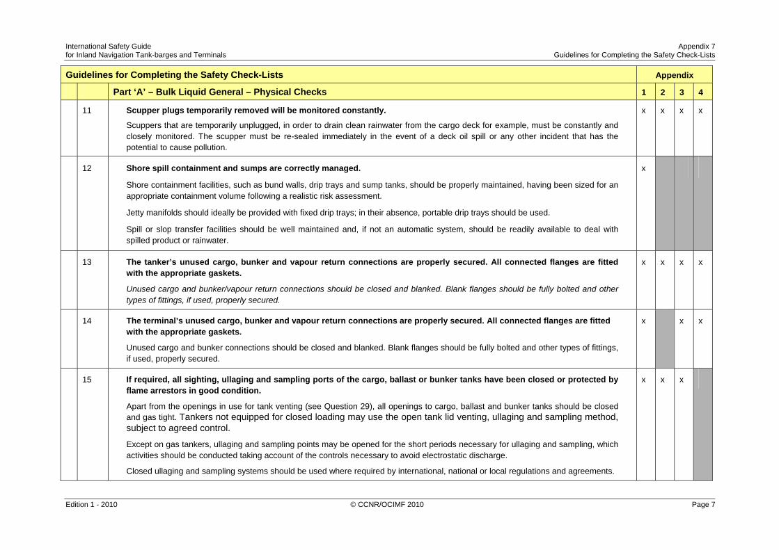
International Safety Guide Appendix 7 for Inland Navigation Tank-barges and Terminals Guidelines for Completing the Safety Check-Lists
Edition 1 - 2010 © CCNR/OCIMF 2010 Page 7
Guidelines for Completing the Safety Check-Lists Appendix
Part ‘A’ – Bulk Liquid General – Physical Checks 1 2 3 4
11 Scupper plugs temporarily removed will be monitored constantly.
Scuppers that are temporarily unplugged, in order to drain clean rainwater from the cargo deck for example, must be constantly and closely monitored. The scupper must be re-sealed immediately in the event of a deck oil spill or any other incident that has the potential to cause pollution.
x x x x
12 Shore spill containment and sumps are correctly managed.
Shore containment facilities, such as bund walls, drip trays and sump tanks, should be properly maintained, having been sized for an appropriate containment volume following a realistic risk assessment.
Jetty manifolds should ideally be provided with fixed drip trays; in their absence, portable drip trays should be used.
Spill or slop transfer facilities should be well maintained and, if not an automatic system, should be readily available to deal with spilled product or rainwater.
x
13 The tanker’s unused cargo, bunker and vapour return connections are properly secured. All connected flanges are fitted with the appropriate gaskets.
Unused cargo and bunker/vapour return connections should be closed and blanked. Blank flanges should be fully bolted and other types of fittings, if used, properly secured.
x x x x
14 The terminal’s unused cargo, bunker and vapour return connections are properly secured. All connected flanges are fitted with the appropriate gaskets.
Unused cargo and bunker connections should be closed and blanked. Blank flanges should be fully bolted and other types of fittings, if used, properly secured.
x x x
15 If required, all sighting, ullaging and sampling ports of the cargo, ballast or bunker tanks have been closed or protected by flame arrestors in good condition.
Apart from the openings in use for tank venting (see Question 29), all openings to cargo, ballast and bunker tanks should be closed and gas tight. Tankers not equipped for closed loading may use the open tank lid venting, ullaging and sampling method, subject to agreed control.
Except on gas tankers, ullaging and sampling points may be opened for the short periods necessary for ullaging and sampling, which activities should be conducted taking account of the controls necessary to avoid electrostatic discharge.
Closed ullaging and sampling systems should be used where required by international, national or local regulations and agreements.
x x x

International Safety Guide Appendix 7 for Inland Navigation Tank-barges and Terminals Guidelines for Completing the Safety Check-Lists
Edition 1 - 2010 © CCNR/OCIMF 2010 Page 8
Guidelines for Completing the Safety Check-Lists Appendix
Part ‘A’ – Bulk Liquid General – Physical Checks 1 2 3 4
16 Sea and overboard discharge valves, when not in use, are closed and visibly secured. The removable parts between ballast and overboard discharge lines and cargo lines are removed.
Experience shows the importance of this item in pollution avoidance on tankers where cargo lines and ballast systems are interconnected. Remote operating controls for such valves should be identified in order to avoid inadvertent opening.
If appropriate, the security of the valves in question should be checked visually.
x x x x
17.1 All external doors, ports and windows in the accommodation, stores and machinery spaces are closed. Engine room vents may be open.
External doors, windows and portholes in the accommodation should be closed during cargo operations. These doors should be clearly marked as being required to be closed during such operations, but at no time should they be locked.
This requirement does not prevent reasonable access to spaces during operations, but doors should not be left open when unattended.
Engine room vents may be left open. However, consideration should be given to closing them where such action would not adversely affect the safe and efficient operation of the engine room spaces served.
x x x
17.2 The LPG domestic installation is isolated at the main stop valve. x x x
18 The tanker’s emergency fire control plans are available.
A set of fire control plans should be available at a prominently marked location for the assistance of shoreside fire-fighting personnel. A crew list should also be included in this enclosure.
x x x
If the tanker is fitted, or is required to be fitted, with an inert gas system (IGS), the following points should be physically checked:
Inert Gas System
19 IGS pressure and oxygen contents measuring equipment are in good working order.
If required, fixed or portable IGS pressure and oxygen content recorders / instruments should be switched on, tested as per manufacturer’s instructions and operating correctly.
x x x

International Safety Guide Appendix 7 for Inland Navigation Tank-barges and Terminals Guidelines for Completing the Safety Check-Lists
Edition 1 - 2010 © CCNR/OCIMF 2010 Page 9
Guidelines for Completing the Safety Check-Lists Appendix
Part ‘A’ – Bulk Liquid General – Physical Checks 1 2 3 4
20 All cargo tank atmospheres are at positive pressure with oxygen content of 8% or less by volume.
Prior to commencement of cargo operations, each cargo tank atmosphere should be checked to verify an oxygen content of 8% or less by volume. Inerted cargo tanks should be kept at a positive pressure at all times.
x x x
20L All inerted tanks are marked or labelled with a warning sign.
For example:
x x x

International Safety Guide Appendix 7 for Inland Navigation Tank-barges and Terminals Guidelines for Completing the Safety Check-Lists
Edition 1 - 2010 © CCNR/OCIMF 2010 Page 10
Guidelines for Completing the Safety Check-List Appendix
Part ‘B’ – Bulk Liquid General – Verbal Verification 1 2 3 4
21 The tanker is ready to move under its own power. A dumb barge without own propulsion means should be able to move with the help of a designated tug at short notice.
The tanker should be able to move under its own power at short notice, unless permission to immobilise the tanker has been granted by the +port authority and the Terminal Representative.
Certain conditions may have to be met for permission to be granted.
x x x
22 There is an effective deck watch in attendance on board and adequate supervision of operations on the tankers and/or ashore.
The operation should be under constant control and supervision on the tankers and/or in the terminal.
Supervision should be aimed at preventing the development of hazardous situations. However, if such a situation arises, the controlling personnel should have adequate knowledge and the means available to take corrective action.
The controlling personnel on the tankers and/or in the terminal should maintain effective communications with their respective supervisors.
All personnel connected with the operations should be familiar with the dangers of the substances handled and should wear appropriate protective clothing and equipment.
x x x x
22L On the tanker(s) and/or the shore, a competent person is appointed who is responsible for the planned cargo handling. x x x
23 There are sufficient personnel on board and ashore to deal with an emergency.
At all times during the tanker’s stay at the terminal or alongside the other tanker, a sufficient number of personnel should be present on board the tankers and/or in the shore installation to deal with an emergency.
x x x x
24.1 The procedures for cargo, bunker and ballast handling have been agreed. x x x

International Safety Guide Appendix 7 for Inland Navigation Tank-barges and Terminals Guidelines for Completing the Safety Check-Lists
Edition 1 - 2010 © CCNR/OCIMF 2010 Page 11
Guidelines for Completing the Safety Check-List Appendix
Part ‘B’ – Bulk Liquid General – Verbal Verification 1 2 3 4
24.2 The outlet pressure of the cargo pump of the tanker is regulated to take account of the admissible working pressure of the equipment ashore or on board the other tanker.
The procedures for the intended operation should be pre-planned. They should be discussed and agreed upon by the Responsible Persons and/or Terminal Representative prior to the start of the operations. Agreed arrangements should be formally recorded and signed by both the Responsible Persons and/or Terminal Representative. Any change in the agreed procedure that could affect the operation should be discussed by both parties and agreed upon. After both parties have reached agreement, substantial changes should be laid down in writing as soon as possible and in sufficient time before the change in procedure takes place. In any case, the change should be laid down in writing within the working period of those supervisors on board and ashore in whose working period agreement on the change was reached.
The operations should be suspended and all deck and vent openings closed on the approach of an electrical storm.
The properties of the substances handled, the equipment of tanker and/or shore installation, and the ability of the tanker’s crew and shore personnel to execute the necessary operations and to sufficiently control the operations are factors which should be taken into account when ascertaining the possibility of handling a number of substances concurrently.
The manifold areas, both on board and ashore, should be safely and properly illuminated during darkness.
The initial and maximum loading rates, topping-off rates and normal stopping times should be agreed, having regard to:
- The nature of the cargo to be handled.
- The arrangement and capacity of the tanker’s cargo lines and gas venting systems.
- The maximum allowable pressure and flow rate in the tanker/shore hoses and loading arms.
- Precautions to avoid accumulation of static electricity.
- Any other flow control limitations.
A record to this effect should be formally made as above.
x x x
24.3 The outlet pressure of the shore’s cargo pump or the other tanker is regulated to take account of the admissible working pressure of the equipment on board the tanker.
See 24.2
x x

International Safety Guide Appendix 7 for Inland Navigation Tank-barges and Terminals Guidelines for Completing the Safety Check-Lists
Edition 1 - 2010 © CCNR/OCIMF 2010 Page 12
Guidelines for Completing the Safety Check-List Appendix
Part ‘B’ – Bulk Liquid General – Verbal Verification 1 2 3 4
25 The emergency signal and shutdown procedure to be used by the tanker and shore have been explained and understood.
The agreed signal to be used in the event of an emergency arising ashore or on board should be clearly understood by shore and/or tanker personnel.
An emergency shutdown procedure should be agreed between tankers and/or shore, formally recorded and signed by both the Responsible Officer and Terminal Representative.
The agreement should state the circumstances in which operations have to be stopped immediately.
Due regard should be given to the possible introduction of dangers associated with the emergency shutdown procedure.
x x x x
26 Material Safety Data Sheets (MSDS), or equivalent, for the cargo transfer have been exchanged where requested.
An MSDS should be available on request to the receiver from the terminal or tankers supplying the product.
As a minimum, such information sheets should provide the constituents of the product by chemical name, name in common usage, UN number (if applicable) and the maximum concentration of any toxic components, expressed as a percentage by volume or as ppm.
x x x
26L The tanker is approved to transport the product to be loaded.
A certified list of approved products to be carried, issued by a competent authority, must be checked, before loading.
x x x x
27 The hazards associated with toxic substances in the cargo being handled have been identified and understood.
Many tanker cargoes contain components that are known to be hazardous to human health. In order to minimise the impact on personnel, information on cargo constituents should be available during the cargo transfer to enable the adoption of proper precautions. In addition, some port states require such information to be readily available during cargo transfer and in the event of an accidental spill. This is particularly relevant to cargoes that could contain H2S, benzene, lead or other additives.
x x x
28 An International Shore Fire Connection has been provided.
If required, the connection must meet the standard requirements and, if not actually connected prior to commencement of operations, should be readily available for use in an emergency.
x x x

International Safety Guide Appendix 7 for Inland Navigation Tank-barges and Terminals Guidelines for Completing the Safety Check-Lists
Edition 1 - 2010 © CCNR/OCIMF 2010 Page 13
Guidelines for Completing the Safety Check-List Appendix
Part ‘B’ – Bulk Liquid General – Verbal Verification 1 2 3 4
29 The agreed tank venting system will be used.
Agreement should be reached and recorded as to the venting system to be used for the operation, taking into account the nature of the cargo and international, national or local regulations and agreements.
There are four basic systems for venting tanks:
1. Open to atmosphere via open ullage ports, protected by suitable flame screens.
2. Fixed venting systems which includes inert gas systems.
3. To shore through a vapour collection system (see Question 32 below).
4. Open to atmosphere (for products without a dangerous goods classification or separately listed in national or international legislation).
x x x
30.1 The requirements for closed operations have been agreed.
It is a requirement of many terminals that, when the tanker is ballasting into cargo tanks, loading or discharging, it operates without recourse to opening ullage and sighting ports. In these cases, tankers will require the means to enable closed monitoring of tank contents, either by a fixed gauging system or by using portable equipment passed through a vapour lock, and preferably backed up by an independent overfill alarm system.
x x x
30.2 The tanker’s vapour return connection, if required, is connected, by means of a vapour return line, to the vapour return connection to the shore or the other tanker.
x x x
30.3 If protection against explosions is required the vapour return line is equipped with a flame arrestor and/or detonation protection.
x x x
31 The operation of the P/V system has been verified. The delivering tanker or shore guarantees that the pumping rate does not exceed the maximum working pressure agreed.
The operation of the P/V valves and/or high velocity vents should be checked using the testing facility provided by the manufacturer. Furthermore, it is imperative that an adequate check is made, visually or otherwise, to ensure that the checklift is actually operating the valve. On occasion, a seized or stiff vent has caused the checklift drive pin to shear and the tanker’s personnel to assume, with disastrous consequences, that the vent was operational.
x x x

International Safety Guide Appendix 7 for Inland Navigation Tank-barges and Terminals Guidelines for Completing the Safety Check-Lists
Edition 1 - 2010 © CCNR/OCIMF 2010 Page 14
Guidelines for Completing the Safety Check-List Appendix
Part ‘B’ – Bulk Liquid General – Verbal Verification 1 2 3 4
32 Where a vapour return line is connected, operating parameters have been agreed.
Where required, a vapour return line, will be used to return hazardous vapours from the cargo tanks to shore or cargo tank to tank.
In case of flammable vapours, the vapour return line should be incorporated with a flame arrestor capable of withstanding a detonation / deflagration. The maximum and minimum operating pressures and any other constraints associated with the operation of the vapour return system should be discussed and agreed by tankers and/or shore personnel.
x x x
33 Independent high level alarms and/or emergency stops, if fitted, are operational and have been tested.
Owing to the increasing reliance placed on gauging systems for closed cargo operations, it is important that such systems are fully operational and that backup is provided in the form of an independent overfill alarm arrangement. The alarm should provide audible and visual indication and should be set at a level that will enable operations to be shutdown prior to the tank being overfilled. Under normal operations, the cargo tank should not be filled higher than the level at which the overfill alarm is set.
Individual overfill alarms should be tested at the tank to ensure their proper operation prior to commencing loading unless the system is provided with an electronic self-testing capability which monitors the condition of the alarm circuitry and sensor and confirms the instrument set point.
x x x x
34 Adequate electrical insulating mean is in place in the tanker/shore cargo and vapour return line connection (if applicable) or between the tankers.
Unless measures are taken to break the continuous electrical path between tankers and/or shore pipework provided by the tanker/shore or tanker/tanker hoses or metallic arms, stray electric currents, mainly from corrosion prevention systems, can cause electric sparks at the flange faces when hoses are being connected and disconnected.
The passage of these currents is usually prevented by an insulating flange inserted at each jetty manifold outlet or incorporated in the construction of metallic arms. Alternatively, the electrical discontinuity may be provided by the inclusion of one length of electrically discontinuous hose in each hose string.
It should be ascertained that the means of electrical discontinuity is in place, that it is in good condition and is not being by-passed by contact with an electrically conductive material.
x x x

International Safety Guide Appendix 7 for Inland Navigation Tank-barges and Terminals Guidelines for Completing the Safety Check-Lists
Edition 1 - 2010 © CCNR/OCIMF 2010 Page 15
Guidelines for Completing the Safety Check-List Appendix
Part ‘B’ – Bulk Liquid General – Verbal Verification 1 2 3 4
35 Shore lines are fitted with a non-return valve, or procedures to avoid back filling have been discussed.
In order to avoid cargo running back when discharge from a tanker is stopped, either due to operational needs or excessive back pressure, the terminal should confirm that it has a positive system that will prevent unintended flow from the shore facility onto the tanker. Alternatively, a procedure should be agreed that will protect the tanker.
x x
36 Smoking requirements are being observed and have been agreed.
No smoking is allowed on board the tankers.
No smoking is allowed on the jetty and the adjacent area, except in buildings and places specified by the Terminal Representative in consultation with the Master.
Buildings, places and rooms designated as areas where smoking is permitted should be clearly marked as such.
x x x x
37 Naked light regulations are being observed and have been agreed.
A naked light or open fire comprises the following: flame, spark formation, naked electric light or any surface with a temperature that is equal to or higher than the auto-ignition temperature of the products handled in the operation.
The use of naked lights or open fires on board the tanker, and within a distance of 25 metres of the tanker, should be prohibited, unless all applicable regulations have been met and agreement reached by the port authority, Terminal Representative and the Master. This distance may have to be extended for tankers of a specialised nature such as gas tankers.
x x x
38 Portable electronic (e.g. communication) device requirements are being observed.
Tanker/shore telephones should comply with the requirements for explosion-proof construction, except when placed and used in a safe space in the accommodation.
Mobile telephones and pagers should not be used in hazardous areas unless approved for such use by a competent authority.
x x x
39 Hand torches (flashlights) are of an approved type.
Battery operated hand torches (flashlights) should be of a safe type, approved by a competent authority. Damaged units, even though they may be capable of operation, should not be used.
x x x
40 Fixed VHF/UHF transceivers and AIS equipment are on the correct power mode or switched off.
Fixed VHF/UHF and AIS equipment should be switched off or on low power (1watt or less) unless the Master, in consultation with the Terminal Representative, has established the conditions under which the installation may be used safely.
x x x

International Safety Guide Appendix 7 for Inland Navigation Tank-barges and Terminals Guidelines for Completing the Safety Check-Lists
Edition 1 - 2010 © CCNR/OCIMF 2010 Page 16
Guidelines for Completing the Safety Check-List Appendix
Part ‘B’ – Bulk Liquid General – Verbal Verification 1 2 3 4
41 Portable VHF/UHF transceivers are of an approved type.
Portable VHF/UHF sets should be of a safe type, approved by a competent authority.
x x x
42 The tanker’s main radio transmitter aerials are earthed and radars are disconnected / switched off.
The tanker’s main radio station should not be used during the tanker’s stay in port, except for receiving purposes. The main transmitting aerials should be disconnected and earthed.
Satellite communications equipment may be used normally, unless advised otherwise.
The tanker’s radar installation should not be used.
x x x
43 Electric cables to portable electrical equipment within the hazardous area are disconnected from power.
The use of portable electrical equipment on wandering leads should be prohibited in hazardous zones during cargo operations, and the equipment preferably removed from the hazardous zone.
Telephone cables in use in the tanker/shore communication system should preferably be routed outside the hazardous zone. Wherever this is not feasible, the cable should be so positioned and protected that no danger arises from its use.
x x x
44 Window type air conditioning units are disconnected.
Window type air conditioning units should be disconnected from their power supply.
x x x
45 Positive pressure is maintained inside the accommodation and/or wheelhouse.
A positive pressure should, when possible, be maintained inside the accommodation/wheelhouse, and procedures or systems should be in place to prevent flammable or toxic vapours from entering accommodation spaces. This can be achieved by air conditioning or similar systems, which draw clean air from non-hazardous locations protected by inlet gas and low pressure alarm systems.
x x x
46 Measures have been taken to ensure sufficient mechanical ventilation in the pumproom.
Pumprooms should be mechanically ventilated and the ventilation system, which should maintain a safe atmosphere throughout the pumproom, should be kept running throughout cargo handling operations. The gas detection system, if fitted, should be functioning correctly.
x x x

International Safety Guide Appendix 7 for Inland Navigation Tank-barges and Terminals Guidelines for Completing the Safety Check-Lists
Edition 1 - 2010 © CCNR/OCIMF 2010 Page 17
Guidelines for Completing the Safety Check-List Appendix
Part ‘B’ – Bulk Liquid General – Verbal Verification 1 2 3 4
47 There is provision for an emergency escape or for emergency boarding positioned ready for use.
In addition to the means of access referred to in Question 1, a safe and quick emergency escape route should be available both on board and ashore. On board the tanker, it may consist of a lifeboat ready for immediate use, preferably at the after end of the tanker, and clear of the moorings. Ideally, a jetty should provide secondary means of escape from the tanker in case the normal access is unusable in an emergency. If the jetty configuration renders such secondary escape by gangway impossible, other means should be considered such as:
- Preparing the ship’s (free-fall) lifeboat for immediate lowering, or
- Rigging of the ship’s accommodation ladder on the side away from the jetty.
If the lifeboat can not be used, other means should be available as a substitution.
National and / or international legislation may impose different or more stringent requirements.
x x x
48 The weather conditions, maximum wind and swell criteria for operations have been agreed.
There are numerous factors which will help determine whether cargo or ballast operations should be discontinued. Discussion between the terminal and/or the tanker should identify limiting factors, which could include:
- Wind speed and direction and the effect on hard arms.
- Wind speed and direction and the effect on mooring integrity.
- Wind speed and direction and the effect on gangways.
- At exposed terminals, swell effects on moorings or gangway safety.
Such limitations should be clearly understood by both parties. The criteria for stopping cargo, disconnecting hoses or arms and vacating the berth should be written in the ‘Remarks’ column of the check-list.
x x x x
49 Security protocols have been agreed between the Tanker(s) Security Responsible Person / Officer and/or the Port Facility Security Officer, if appropriate.
In states that are signatories to SOLAS, the ISPS Code requires that the Tanker(s) Security Responsible Person / Officer and/or the Port Facility Security Officer co-ordinate the implementation of their respective security plans with each other.
x x x

International Safety Guide Appendix 7 for Inland Navigation Tank-barges and Terminals Guidelines for Completing the Safety Check-Lists
Edition 1 - 2010 © CCNR/OCIMF 2010 Page 18
Guidelines for Completing the Safety Check-List Appendix
Part ‘B’ – Bulk Liquid General – Verbal Verification 1 2 3 4
49L Security protocols have been agreed for the crew of one tanker to board the other tanker. The location of the security protocol for boarding tanker is: ……………………..
x x
50 Where appropriate, procedures have been agreed for receiving nitrogen supplied from shore, either for inerting or purging tanker’s tanks, or for line clearing into the tanker.
Tanker and shore should agree in writing on the inert gas supply, specifying the volume required, and the flow rate in cubic metres per minute. The sequence of opening valves before beginning the operation and after completion should be agreed, so that the tanker remains in control of the flow. Attention should be given to the adequacy of open vents on a tank in order to avoid the possibility of over-pressurisation.
The tank pressure should be closely monitored throughout the operation.
The tanker’s agreement should be sought when the terminal wishes to use compressed nitrogen (or air) as a propellant, either for pigging to clear shore lines into the tanker or to press cargo out of shore containment. The tanker should be informed of the pressure to be used and the possibility of receiving gas into a cargo tank.
x x x
Inert Gas System
51 The IGS is fully operational and in good working order.
The inert gas system should be in safe working condition with particular reference to all interlocking trips and associated alarms, deck seal, non-return valve, pressure regulating control system, main deck IG line pressure indicator, individual tank IG valves (when fitted) and deck P/V breaker.
Individual tank IG valves (if fitted) should have easily identified and fully functioning open/close position indicators.
x x x
52 Deck seals, or equivalent, are in good working order.
It is essential that the deck seal arrangements are in a safe condition. In particular, the water supply arrangements to the seal and the proper functioning of associated alarms should be checked.
x x x
53 Liquid levels in pressure/vacuum breakers are correct, if applicable.
Checks should be made to ensure that the liquid level in the P/V breaker complies with manufacturer’s recommendations.
x x x

International Safety Guide Appendix 7 for Inland Navigation Tank-barges and Terminals Guidelines for Completing the Safety Check-Lists
Edition 1 - 2010 © CCNR/OCIMF 2010 Page 19
Guidelines for Completing the Safety Check-List Appendix
Part ‘B’ – Bulk Liquid General – Verbal Verification 1 2 3 4
54 The fixed and portable oxygen analysers have been calibrated and are working properly.
All fixed and portable oxygen analysers should be tested and checked as required by the Company and/or manufacturer’s instructions and should be operating correctly.
The in-line oxygen analyser/recorder and sufficient portable oxygen analysers should be working properly.
The calibration certificate should show that its validity is as required by the tanker’s SMS.
x x x
55 All the individual tank IG valves (if fitted) are correctly set and locked.
For both loading and discharge operations, it is normal and safe to keep all individual tank IG supply valves (if fitted) open in order to prevent inadvertent under or over-pressurisation. In this mode of operation, each tank pressure will be the same as the deck main IG pressure and thus the P/V breaker will act as a safety valve in case of excessive over or under-pressure. If individual tank IG supply valves are closed for reasons of potential vapour contamination or de-pressurisation for gauging etc, then the status of the valve should be clearly indicated to all those involved in cargo operations. Each individual tank IG valve should be fitted with a locking device under the control of a Responsible Officer.
x x x
56 All personnel in charge of cargo operations are aware that, in the event of failure of the inert gas plant, discharge operations should cease and the terminal and/or the other tanker be advised.
In the case of failure of the IG plant, the cargo discharge, de-ballasting and tank cleaning operations should cease and the terminal be advised.
Under no circumstances should the tanker’s personnel allow the atmosphere in any tank to fall below atmospheric pressure.
x x x
Crude Oil Washing
57 N/A
58 N/A

International Safety Guide Appendix 7 for Inland Navigation Tank-barges and Terminals Guidelines for Completing the Safety Check-Lists
Edition 1 - 2010 © CCNR/OCIMF 2010 Page 20
Guidelines for Completing the Safety Check-List Appendix
Part ‘B’ – Bulk Liquid General – Verbal Verification 1 2 3 4
Tank Cleaning
59 Tank cleaning operations are planned during the tanker’s stay alongside the other tanker / shore installation.
During the pre-transfer discussion between the Responsible Person / Officer and/or Terminal Representative, it should be established whether any tank cleaning operations are planned while the tanker is alongside and the check-list should be annotated accordingly.
x x x x
60 If ‘yes’, the procedures and approvals for tank cleaning have been agreed.
It should be confirmed that all necessary approvals that may be required to enable tank cleaning to be undertaken alongside have been obtained in line with local legislation and regulations from relevant authorities. The method of tank cleaning to be used should be agreed, together with the scope of the operation.
x x x x
61 Permission has been granted for gas freeing operations by the competent authority.
It should be confirmed that all necessary approvals that may be required to enable gas freeing to be undertaken alongside, have been obtained in line with local legislation and regulations from the relevant authorities.
x x x

International Safety Guide Appendix 7 for Inland Navigation Tank-barges and Terminals Guidelines for Completing the Safety Check-Lists
Edition 1 - 2010 © CCNR/OCIMF 2010 Page 21
Guidelines for Completing the Safety Check-List Appendix
Part ‘C’ – Bulk Liquid Chemicals – Verbal verification 1 2 3 4
1 Material Safety Data Sheets, or equivalent, are available giving the necessary data for the safe handling of the cargo.
Information on the product to be handled should be available on board the tanker and ashore and should include:
- A full description of the physical and chemical properties, including reactivity, necessary for the safe containment and transfer of the cargo.
- Action to be taken in the event of spills or leaks.
- Countermeasures against accidental personal contact.
- Fire-fighting procedures and fire-fighting media.
x x x
2 A manufacturer’s inhibition certificate, where applicable, has been provided.
Where cargoes are required to be stabilised or inhibited in order to be handled, tankers should be provided with a certificate from the manufacturer stating:
- Name and amount of inhibitor added.
- Date inhibitor was added and the normal duration of its effectiveness.
- Any temperature limitations affecting the inhibitor.
- The action to be taken should the length of the voyage exceed the effective lifetime of the inhibitor.
Document should be on board before departure.
x x x
3 Sufficient protective clothing and equipment (including self-contained breathing apparatus) is ready for immediate use and is suitable for the product being handled.
Suitable protective equipment (including self-contained breathing apparatus and protective clothing) appropriate to the specific dangers of the product handled, should be readily available in sufficient quantity for operational personnel both on board and ashore.
x x x

International Safety Guide Appendix 7 for Inland Navigation Tank-barges and Terminals Guidelines for Completing the Safety Check-Lists
Edition 1 - 2010 © CCNR/OCIMF 2010 Page 22
Guidelines for Completing the Safety Check-List Appendix
Part ‘C’ – Bulk Liquid Chemicals – Verbal verification 1 2 3 4
4 Countermeasures in the event of accidental personal contact with the cargo have been agreed.
Sufficient and suitable means should be available to neutralise the effects and remove small quantities of spilled products. Should unforeseen personal contact occur, in order to limit the consequences it is important that sufficient and suitable countermeasures are undertaken.
The MSDS should contain information on how to handle such contact with reference to the special properties of the cargo, and personnel should be aware of the procedures to follow.
A suitable safety shower and eye rinsing equipment should be fitted and ready for instant use in the immediate vicinity of places on board or ashore where operations regularly take place.
x x x
5 The cargo handling rate is compatible with the automatic shutdown system, if in use.
Automatic shutdown valves may be fitted on the tanker(s) and/or ashore. The action of these is automatically initiated by, for example, a certain level being reached in the tanker(s) or shore tank being filled. Where such systems are used, the cargo handling rate should be established to prevent pressure surges from the automatic closure of valves causing damage to tanker or shore line systems. Alternative means, such as a re-circulation system and buffer tanks, may be fitted to relieve the pressure surge created.
A written agreement should be made between the Responsible Person / Officer and Terminal Representative indicating whether the cargo handling rate will be adjusted or alternative systems will be used.
x x x
6 Cargo system gauges and alarms are correctly set and in good order.
Tankers and shore cargo system gauges and alarms should be checked regularly to ensure they are in good working order.
In cases where it is possible to set alarms to different levels, the alarm should be set to the required level.
x x x
7 Portable vapour detection instruments are readily available for the products being handled.
The equipment provided should be capable of measuring, where appropriate, flammable and/or toxic levels.
Suitable equipment should be available for operational testing of those instruments capable of measuring flammability. Operational testing should be carried out before using the equipment. Calibration should be carried out in accordance with the Safety Management System.
x x x

International Safety Guide Appendix 7 for Inland Navigation Tank-barges and Terminals Guidelines for Completing the Safety Check-Lists
Edition 1 - 2010 © CCNR/OCIMF 2010 Page 23
Guidelines for Completing the Safety Check-List Appendix
Part ‘C’ – Bulk Liquid Chemicals – Verbal verification 1 2 3 4
8 Information on fire-fighting equipment and procedures has been exchanged.
Information should be exchanged on the availability of fire-fighting equipment and the procedures to be followed in the event of a fire on board or ashore.
Special attention should be given to any products that are being handled which may be water reactive or which require specialised fire-fighting procedures.
x x x
9 Transfer hoses and gaskets are of suitable material, resistant to the action of the products being handled.
Each transfer hose should be indelibly marked so as to allow the identification of the products for which it is suitable, its specified maximum working pressure, the test pressure and last date of testing at this pressure, and, if used at temperatures other than ambient, its maximum and minimum service temperatures.
x x x x
10 Cargo handling is performed with the permanent installed pipeline system.
All cargo transfer should be through permanently installed pipeline systems on board and ashore.
Should it be necessary, for specific operational reasons, to use portable cargo lines on board or ashore, care should be taken to ensure that these lines are correctly positioned and assembled in order to minimise any additional risks associated with their use. Where necessary, the electrical continuity of these lines should be checked and their length should be kept as short as possible.
The use of non-permanent transfer equipment inside tanks is not generally permitted unless specific approvals have been obtained.
Whenever cargo hoses are used to make connections within the tanker(s) and/or shore permanent pipeline system, these connections should be properly secured, kept as short as possible and be electrically continuous to the tanker(s) and/or shore pipeline respectively. Any hoses used must be suitable for the service and be properly tested, marked and certified.
x x x
11 Where appropriate, procedures have been agreed for receiving nitrogen supplied from shore, either for inerting or purging tanker’s tanks, or for line clearing into the tanker.
Tanker(s) and/or shore should agree in writing on the nitrogen supply, specifying the volume required, and the flow rate in cubic metres per minute. The sequence of opening valves before beginning the operation and after completion should be agreed, so that the tanker(s) remains in control of the flow. Attention should be given to the adequacy of open vents on a tank in order to avoid the possibility of over-pressurisation.
The tank pressure should be closely monitored throughout the operation.
The tanker’s agreement should be sought when the terminal / discharging tanker wishes to use compressed nitrogen (or air) for line clearing. The (receiving) tanker should be informed of the pressure to be used and the possibility of receiving gas into a cargo tank.
x x

International Safety Guide Appendix 7 for Inland Navigation Tank-barges and Terminals Guidelines for Completing the Safety Check-Lists
Edition 1 - 2010 © CCNR/OCIMF 2010 Page 24
Guidelines for Completing the Safety Check-List Appendix
Part ‘C’ – Bulk Liquid Chemicals – Verbal verification 1 2 3 4
12 If required, the cargo deck water spray system is ready for immediate use.
A good working water spray can be used to avoid increasing of the cargo deck temperature by radiation. x x x

International Safety Guide Appendix 7 for Inland Navigation Tank-barges and Terminals Guidelines for Completing the Safety Check-Lists
Edition 1 - 2010 © CCNR/OCIMF 2010 Page 25
Guidelines for Completing the Safety Check-List Appendix
Part ‘D’ – Bulk Liquefied Gases – Verbal Verification 1 2 3 4
1 Material Safety Data Sheets, or equivalent, are available giving the necessary data for the safe handling of the cargo.
Information on each product to be handled should be available on board the tanker(s) and/or ashore before and during the operation.
Cargo information, in a written format, should include:
- A full description of the physical and chemical properties necessary for the safe containment of the cargo.
- Action to be taken in the even of spills or leaks.
- Countermeasures against accidental personal contact.
- Fire-fighting procedures and fire-fighting media.
- Any special equipment needed for the safe handling of the particular cargo(es).
- Minimum allowable inner hull steel temperatures.
- Emergency procedures.
x x x
2 A manufacturer’s inhibition certificate, where applicable, has been provided.
Where cargoes are required to be stabilised or inhibited in order to be handled, tankers should be provided with a certificate from the manufacturer stating:
- Name and amount of inhibitor added.
- Date inhibitor was added and the normal duration of its effectiveness.
- Any temperature limitations affecting the inhibitor.
- The action to be taken should the length of the voyage exceed the effective lifetime of the inhibitor.
Document should be on board before departure.
x x x
3 The cargo deck water spray system is ready for immediate use.
In cases where flammable or toxic products are handled, water spray systems should be tested regularly. Details of the last tests should be exchanged.
During operations, the systems should be kept ready for immediate use.
x x x

International Safety Guide Appendix 7 for Inland Navigation Tank-barges and Terminals Guidelines for Completing the Safety Check-Lists
Edition 1 - 2010 © CCNR/OCIMF 2010 Page 26
Guidelines for Completing the Safety Check-List Appendix
Part ‘D’ – Bulk Liquefied Gases – Verbal Verification 1 2 3 4
4 Sufficient suitable protective clothing and equipment (including self-contained breathing apparatus) is ready for immediate use and is suitable for the products being handled.
Suitable protective equipment, including self-contained breathing apparatus, eye protection and protective clothing appropriate to the specific dangers of the product handled should be available in sufficient quantity for operational personnel, both on board and ashore.
Storage places for this equipment should be protected from the weather and be clearly marked.
All personnel directly involved in the operation should utilise this equipment and clothing whenever the situation requires.
Personnel required to use breathing apparatus during operations should be trained in its safe use. Untrained personnel and personnel with facial hair should not be selected for operations involving the use of breathing apparatus.
x x x
5 Hold and inter-barrier spaces are properly inerted or filled with dry air, as required.
The spaces that are required to be inerted by the IMO Gas Carrier Codes should be checked by tanker’s personnel prior to arrival.
x x x
6 All remote control valves are in working order.
All tanker(s) and/or shore cargo system remote control valves and their position-indicating systems should be tested regularly. Details of the last tests should be exchanged.
x x x
7 The required cargo pumps and compressors are in good order, and the maximum working pressures have been agreed between (the two) tanker(s) and/or shore.
Agreement in writing should be reached on the maximum allowable working pressure in the cargo line system during operations.
x x x
8 Re-liquefaction or boil-off control equipment is in good order.
It should be verified that re-liquefaction and boil-off control systems, if required, are functioning correctly prior to commencement of operations.
x x x
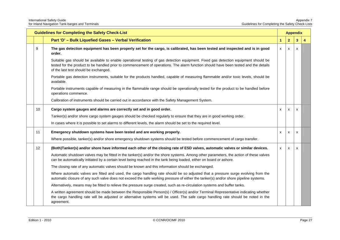
International Safety Guide Appendix 7 for Inland Navigation Tank-barges and Terminals Guidelines for Completing the Safety Check-Lists
Edition 1 - 2010 © CCNR/OCIMF 2010 Page 27
Guidelines for Completing the Safety Check-List Appendix
Part ‘D’ – Bulk Liquefied Gases – Verbal Verification 1 2 3 4
9 The gas detection equipment has been properly set for the cargo, is calibrated, has been tested and inspected and is in good order.
Suitable gas should be available to enable operational testing of gas detection equipment. Fixed gas detection equipment should be tested for the product to be handled prior to commencement of operations. The alarm function should have been tested and the details of the last test should be exchanged.
Portable gas detection instruments, suitable for the products handled, capable of measuring flammable and/or toxic levels, should be available.
Portable instruments capable of measuring in the flammable range should be operationally tested for the product to be handled before operations commence.
Calibration of instruments should be carried out in accordance with the Safety Management System.
x x x
10 Cargo system gauges and alarms are correctly set and in good order.
Tanker(s) and/or shore cargo system gauges should be checked regularly to ensure that they are in good working order.
In cases where it is possible to set alarms to different levels, the alarm should be set to the required level.
x x x
11 Emergency shutdown systems have been tested and are working properly.
Where possible, tanker(s) and/or shore emergency shutdown systems should be tested before commencement of cargo transfer.
x x x
12 (Both)Tanker(s) and/or shore have informed each other of the closing rate of ESD valves, automatic valves or similar devices.
Automatic shutdown valves may be fitted in the tanker(s) and/or the shore systems. Among other parameters, the action of these valves can be automatically initiated by a certain level being reached in the tank being loaded, either on board or ashore.
The closing rate of any automatic valves should be known and this information should be exchanged.
Where automatic valves are fitted and used, the cargo handling rate should be so adjusted that a pressure surge evolving from the automatic closure of any such valve does not exceed the safe working pressure of either the tanker(s) and/or shore pipeline systems.
Alternatively, means may be fitted to relieve the pressure surge created, such as re-circulation systems and buffer tanks.
A written agreement should be made between the Responsible Person(s) / Officer(s) and/or Terminal Representative indicating whether the cargo handling rate will be adjusted or alternative systems will be used. The safe cargo handling rate should be noted in the agreement.
x x x

International Safety Guide Appendix 7 for Inland Navigation Tank-barges and Terminals Guidelines for Completing the Safety Check-Lists
Edition 1 - 2010 © CCNR/OCIMF 2010 Page 28
Guidelines for Completing the Safety Check-List Appendix
Part ‘D’ – Bulk Liquefied Gases – Verbal Verification 1 2 3 4
13 Information has been exchanged between tanker(s) and/or shore on the maximum/ minimum temperatures/pressures of the cargo to be handled.
Before operations commence, information should be exchanged between the Responsible Person(s) / Officer and Terminal Representatives on cargo temperature/pressure requirements.
This information should be in writing.
x x x
14 Cargo tanks are protected against inadvertent overfilling at all times while any cargo operations are in progress.
Automatic shutdown systems are normally designed to close the liquid valves, and if discharging, to trip the cargo pumps, should the liquid level in any tank rise above the maximum permitted level. This level must be accurately set and the operation of the device should be tested at regular intervals.
If tanker(s) and/or shore shutdown systems are to be inter-connected, then their operation must be checked before cargo transfer begins.
x x x
15 The compressor room is properly ventilated, the electrical motor room is properly pressurised and the alarm system is working.
Fans should be run for at least 10 minutes before cargo operations commence and then continuously during cargo operations.
Audible and visual alarms, provided at airlocks associated with compressor/motor rooms, should be tested regularly.
x x x
16 Cargo tank relief valves are set correctly and actual relief valve settings are clearly and visibly displayed.
In cases where cargo tanks are permitted to have more than one relief valve setting, it should be verified that the relief valve is set as required by the cargo to be handled and that the actual setting of the relief valve is clearly and visibly displayed on board the tanker(s). Relief valve settings should be recorded in the check-list.
x x x
17 The operating parameter (opening pressure) of the pressure valve (MARV) of the tanker have been considered and agreed.
This is the abbreviation for the Maximum Allowable Relief Valve setting on a tanker's cargo tank - as stated on the tanker's Certificate of Fitness / Approval.
x x x

International Safety Guide Appendix 7 for Inland Navigation Tank-barges and Terminals Guidelines for Completing the Safety Check-Lists
Edition 1 - 2010 © CCNR/OCIMF 2010 Page 29
Guidelines for Completing the Safety Check-List Appendix
Part ‘D’ – Bulk Liquefied Gases – Verbal Verification 1 2 3 4
18 The (port) authorities have been notified prior to cargo handling, if required. x x x
19 If required by the (port) authorities, an external co-ordinator has been appointed and is on board as co-ordinator responsible for the planned cargo handling between the two tankers.
x x


![Chapter 33en Isgintt 062010[1]](https://img.pdfslide.us/doc/110x75/5571ff8349795991699d6c60/chapter-33en-isgintt-0620101.jpg)