Embed Size (px)
Citation preview
XM1540S AT Commands Reference Manual
No. XM1540S-A00-107 xmodus swiss GmbH 1 / 46
ISDN Modem XM1540S AT Commands Reference Manual
Version 107
Released 21. Oktober 2009
XM1540S AT Commands Reference Manual
No. XM1540S-A00-107 xmodus swiss GmbH 2 / 46
Information provided by xmodus swiss GmbH is believed to be accurate and reliable. However, no responsibility is assumed by xmodus swiss for its use, nor any infringement of patents or other rights of third parties which may result from its use. No license is granted by implication or otherwise under any patent rights of xmodus swiss other than for circuitry embodied in xmodus products. Xmodus swiss reserves the right to change circuitry at any time without notice. This document is subject to change without notice.
Product names or services listed in this publication are for identification purposes only, and may be trademarks or registered trademarks of their respective companies. All other marks mentioned herein are the property of their respective owners. © 2009 xmodus swiss GmbH Printed in Switzerland All Rights Reserved
XM1540S AT Command Reference Manual
No. XM1540S-A00-107 xmodus swiss GmbH 3 / 46
Table of Contents
1. INTRODUCTION ........................................................................................................ 5
1.1 OVERVIEW ............................................................................................................. 5
1.2 PRODUCT DESCRIPTION ..................................................................................... 5
2. SYNTAX AND PROCEDURES................................................................................... 6
2.1 ALPHABET.............................................................................................................. 6
2.2 DTE COMMAND LINES .......................................................................................... 6
3. AT COMMAND SET ................................................................................................... 8
3.2 AT COMMANDS HELP SCREENS ......................................................................... 9
3.3 STANDARD AT COMMANDS ............................................................................... 11
3.4 AT& COMMANDS ................................................................................................. 16
3.5 SPECIAL CONFIGURATION COMMANDS .......................................................... 18
3.6 ISDN SERVICES COMMANDS............................................................................. 19
3.7 ISDN CONFIGURATION COMMANDS................................................................. 20
4. S-REGISTERS.......................................................................................................... 21
4.1 ATSn Read / Write S-Register.............................................................................. 21
4.2 FACTORY DEFAULTS.......................................................................................... 21
4.3 S-REGISTER SUMMARY ..................................................................................... 22
4.4 S-REGISTER DEFINITIONS................................................................................. 23
5. MESSAGES.............................................................................................................. 31
5.1 AT Commands relating to message formats. ........................................................ 31
5.2 Message formats. .................................................................................................. 33
5.3 Message formats. .................................................................................................. 34
5.4 Message formats. .................................................................................................. 35
5.5 CALLING NUMBER REPORT (CLIP) ................................................................... 36
5.6 ISDN ERROR CAUSE REPORT........................................................................... 36
6. X.31 CALL SETUP.................................................................................................... 37
6.1 Setup outgoing X.31 call........................................................................................ 37
6.2 Reporting of X.25 causes and diagnostic codes ................................................... 39
XM1540S AT Commands Reference Manual
No. XM1540S-A00-107 xmodus swiss GmbH 4 / 46
7. INTEGRATED PAD (X.3)......................................................................................... 40
7.1 Command Mode of X.3 PAD ................................................................................. 40
7.2 X.3 Parameter Set ................................................................................................. 40
7.3 International X.3 Parameters 1 … 20 .................................................................... 40
7.4 Table of the implemented standard profile. ........................................................... 42
8. FIRMWARE UPDATE............................................................................................... 43
9. AUDIO MODES ........................................................................................................ 44
9.1 AT Command Specifications: ................................................................................ 44
A. APPENDIX A ............................................................................................................ 46
A.1 TABLE OF ISDN CAUSES (ETSI CAUSE VALUES) ............................................ 46
XM1540S AT Command Reference Manual
No. XM1540S-A00-107 xmodus swiss GmbH 5 / 46
1. INTRODUCTION 1.1 OVERVIEW
This manual describes the AT Commands and the S-Registers for the following xmodus Socket Modem families:
XM1540S ISDN Modem AL5068S ISDN Socket Modem (3V Version) AL5068SI-3V ISDN Socket Modem (3V Version and IOM-2 bus)
The description apply to all these isdn-modems with any differences between product families noted. Refer to Modem Firmware Release notes for commands applicable to modem firmware.
1.2 PRODUCT DESCRIPTION
The xmodus AL5068S, AL5068S-3V and AL5068SI Socket Modem Family provides the OEM with a complete ISDN data/voice/speakerphone modem in a compact socket-mountable module. This modules enables any devices to send and receive data over the ISDN network. The European EuroISDN DSS-1 ISDN network is supported. The module is fully approved and homologated and conforms to the CE regulations. This gives fastest time-to-market to ISDN-enable any devices. The compact size and high level of integration of the Socket Modem minimizes real estate and cost for motherboard and box modem applications. Its low power consumption makes it ideal for a wide variety of embedded control applications. The pin compatibility between the full range of Analog Series Socket Modems, ISDN and GSM Socket Modems allows upgrading and production configurability without hardware changes. As a data modem, the AL5068S Socket Modem can send and receive data at speeds up to 64kbps and 128kbps in the 2-channel version. B-Channel protocols such as V.110, V.120, PPP, transparent and X.75 are supported. For X.25 networks, X.31 Case A and X.31 Case B (D- and B-channel) is supported. The integrated X.3 PAD can be used for data transfer to the X.25 network. The AL5068SI-3V Socket Modem supports Voice features. By adding two external PCM Codecs the modem supports two independent analog voice ports. Digital voice transfer is also supported.
XM1540S AT Commands Reference Manual
No. XM1540S-A00-107 xmodus swiss GmbH 6 / 46
2. SYNTAX AND PROCEDURES
The command and response syntax and procedures generally conform to referenced recommendations and standards. Since these recommendations and standards describe characteristics universal to a large installed base of modems to a maximum degree, there may be syntax and procedural differences due to extensions and behavioral differences in implemented commands, parameters, and responses beyond that described in these recommendations and standards.
The syntax and procedures described in this section are based on V.25ter with additional information included for implemented extensions and behavioral differences beyond V.25ter.
2.1 ALPHABET
The T.50 International Alphabet 5 (IA5) is used in this document. Only the low-order seven bits of each character are significant to the modem; any eight or higher-order bit(s), if present, are ignored for the purpose of identifying commands and parameters. Lower-case characters are considered identical for their upper-case equivalents when received by the modem from the DTE. Result codes from the modem are in upper-case.
2.2 DTE COMMAND LINES
Words enclosed in <angle brackets> are referenced to syntactical elements. The brackets are not used when the words appear in a command line, the brackets are not used. Words enclosed in [square brackets] represent optional items which may be omitted from the command line at the specified point. The square brackets are not used when the words appear in the command line. Other characters that appear in syntax descriptions must as included as shown.
2.2.1 Command Line General Format
A command line is made up of three elements: the prefix, the body, and the termination character. The command line prefix consists of the characters “AT” or “at” or, to repeat the execution of the previous command line, the characters “A/” or “a/”. The body is made up of individual commands described in this document. Space characters (IA52/0) are ignored and may be used freely for formatting purposes, unless they are embedded in numeric or string constants. The termination character may not appear in the body. The modem can accept at least 80 characters in the body.
The termination character may not be selected by the user, the default is CR. Example: AT&FE0Q1S0=1S96=1<CR>
XM1540S AT Command Reference Manual
No. XM1540S-A00-107 xmodus swiss GmbH 7 / 46
2.2.2 Command Line Editing
The character <BS> is interpreted as a request from the DTE to the modem to delete the previous character.
2.2.3 Command Line Echo
The modem may echo characters received from the DTE during command state and online command state back to the DTE, depending on the setting of the ATEn command. If so enabled, characters received from the DTE are echoed in the same format as received.
2.2.4 Repeating a Command Line
If the prefix “A/” or “a/” is received, the modem immediately executes once again the body of the preceding command line. No editing is possible, and no termination character is necessary. A command line may be repeated multiple times in this manner. Responses to the repeated command line are issued using format of the original command line. If “A/” is received before any command line has been executed, the preceding command line is assumed to have been empty (that results in an OK result code).
2.2.5 Factory Settings
The parameter settings of the isdn-modem are pre-configured by the factory defaults. This factory defaults can be reloaded at any time by using the AT&F command. The parameter settings will be changed when using any AT commands which affects the configuration of the modem. This changes can be permanently stored by using the AT&W command. The factory defaults are identified for each command and in the S-Register descriptions. A configuration (profile) consists of a subset of S-Registers. AT&F = Restore factory configuration. AT&W = Store current configuration. Result codes: OK
2.2.6 Escape Code Sequence
When the modem has established a connection and has entered on-line data mode, it is possible to break into the data transmission in order to issue further commands to the modem in an on-line command mode. This is achieved by the DTE sending to the modem a sequence of three ASCII characters specified by register S2. The default character is '+'. The maximum time allowed between receipt of the last character of the three escape character sequence from the DTE and sending of the OK result code to the DTE is controlled by the S12 register (default 1 sec.). The escape characters will be transmitted transparent to the remote side.
Example: [1s pause] <+><+><+> [1s pause]
XM1540S AT Commands Reference Manual
No. XM1540S-A00-107 xmodus swiss GmbH 8 / 46
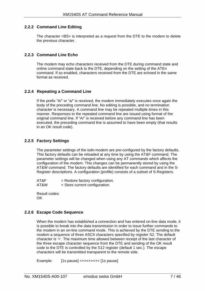
3. AT COMMAND SET
STANDARD COMMANDS SPECIAL COMMANDS A/ Repeat lst command line AT%B0 Autobaud enabled AT? Help Screens AT%B1 Local baudrate = 1200bps ATA Accept incoming call AT%B2 Local baudrate = 24000ps ATB0 V.110 / B-Channel protocols AT%B3 Local baudrate = 4800bps ATB1 V.120 AT%B4 Local baudrate = 9600bps ATB3 PPP AT%B5 Local baudrate = 19200bps ATB4 Transparent speech AT%B6 Local baudrate = 38400bps ATB5 Transparent data AT%B7 Local baudrate = 57600bps ATB6 HDLC AT%B8 Local baudrate = 115200bps ATB10 X.75 AT%B9 Local baudrate = 230400bps ATB20 X.31 / B-Channel AT%W0 AL5500S Message mode ATB21 X.31 / D-Channel AT%W1 AL5064S Message mode ATB40 Transparent IOM-2 (speech) AT%W2 Modem Message modce ATB41 Transparent IOM-2 (data) AT%V0 CONNECT only ATE0 Local Echo off AT%V1 CONNECT + B-Ch. PROT ATE1 Local Echo on AT%V2 CONNECT + LSP + PROT ATH Disconnect ATI0 Modem Type AT**DBITS Set number of data bits ATI3 Firmware Version AT**PRTY Set parity ATI4 Manufacturer ATMn Table of authorized callers ISDN SERVICE COMMANDS ATN3 V.110 Baudrate = 4800bps AT$M Received Called Line ID ATN4 V.110 Baudrate = 9600bps AT$O Received CLIP ATN5 V.110 Baudrate = 19200bps AT$Pn Define X.3 PAD parameters ATN6 V.110 Baudrate = 38400bps AT$Z=n Define own MSN ATO Return to online state ATQ0 Result codes enabled ISDN CONFIGURATION ATQ1 Result codes disabled AT**BSIZE Set B-Channel block size ATSn S-Register settings =64 Set block size to 64 ATV0 Short from result codes =128 Set block size to 128 ATV1 Text form result codes =256 Set block size to 256 ATW0 ISDN result codes disabled =512 Set block size to 512 ATW1 ISDN result codes numeric =1024 Set block size to 1024 ATW2 ISDN result codes text =2048 Set block size to 2048 ATW3 ISDN result codes text+time AT**DTE Set B-Channel L2 address ATX0 Extented result codes off =0 Calling = DTE, called = DCE ATX1 Busy / No Dialtone off =1 TA reacts as DTE ATX2 Busy off =3 TA reacts as DCE ATX3 No Dialtone off AT**K Set L2 window size ATX4 All result codes on = 1 ..7 ATZ Load stored settings
AT&.. COMMANDS AT&C0 DCD always on AT&C1 DCD indicates connect state FLASH COMMAND AT&D0 DTR ignored AT**FLASH is used for firmware update AT&D2 DTR not ignored AT&D4 DTR only for disconnect AT&F Load factory defaults AT&K0 Flow control off AT%R Automatic reboot AT&K3 RTS/CTS Flow control AT*R Reboot AT&K5 RTS/CTS Flow control AT&V Display configuration AT&W Store active configuration
XM1540S AT Command Reference Manual
No. XM1540S-A00-107 xmodus swiss GmbH 9 / 46
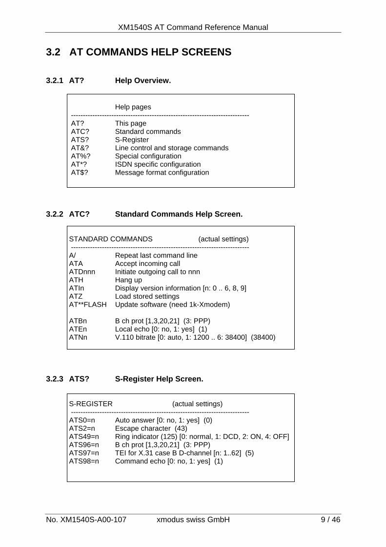
3.2 AT COMMANDS HELP SCREENS 3.2.1 AT? Help Overview.
Help pages --------------------------------------------------------------------------- AT? This page ATC? Standard commands ATS? S-Register AT&? Line control and storage commands AT%? Special configuration AT*? ISDN specific configuration AT$? Message format configuration
3.2.2 ATC? Standard Commands Help Screen.
STANDARD COMMANDS (actual settings) --------------------------------------------------------------------------- A/ Repeat last command line ATA Accept incoming call ATDnnn Initiate outgoing call to nnn ATH Hang up ATIn Display version information [n: 0 .. 6, 8, 9] ATZ Load stored settings AT**FLASH Update software (need 1k-Xmodem) ATBn B ch prot [1,3,20,21] (3: PPP) ATEn Local echo [0: no, 1: yes] (1) ATNn V.110 bitrate [0: auto, 1: 1200 .. 6: 38400] (38400)
3.2.3 ATS? S-Register Help Screen.
S-REGISTER (actual settings) --------------------------------------------------------------------------- ATS0=n Auto answer [0: no, 1: yes] (0) ATS2=n Escape character (43) ATS49=n Ring indicator (125) [0: normal, 1: DCD, 2: ON, 4: OFF] ATS96=n B ch prot [1,3,20,21] (3: PPP) ATS97=n TEI for X.31 case B D-channel [n: 1..62] (5) ATS98=n Command echo [0: no, 1: yes] (1)
XM1540S AT Commands Reference Manual
No. XM1540S-A00-107 xmodus swiss GmbH 10 / 46
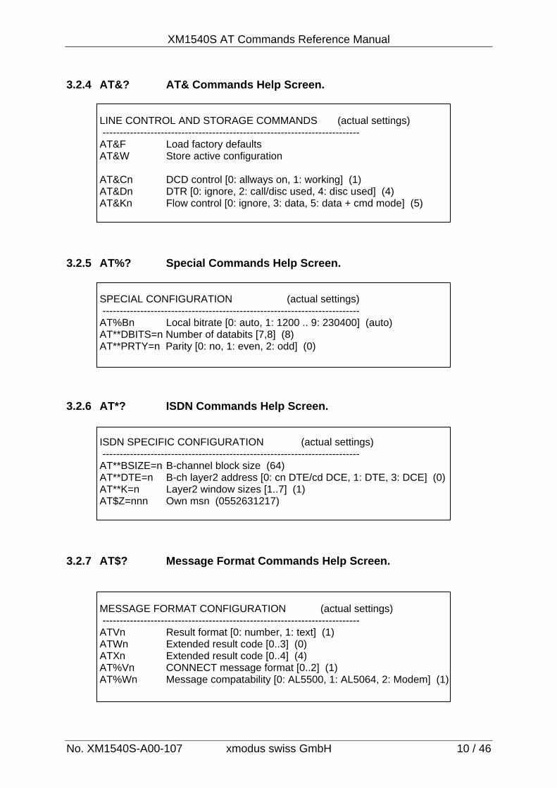
3.2.4 AT&? AT& Commands Help Screen.
LINE CONTROL AND STORAGE COMMANDS (actual settings) --------------------------------------------------------------------------- AT&F Load factory defaults AT&W Store active configuration AT&Cn DCD control [0: allways on, 1: working] (1) AT&Dn DTR [0: ignore, 2: call/disc used, 4: disc used] (4) AT&Kn Flow control [0: ignore, 3: data, 5: data + cmd mode] (5)
3.2.5 AT%? Special Commands Help Screen.
SPECIAL CONFIGURATION (actual settings) --------------------------------------------------------------------------- AT%Bn Local bitrate [0: auto, 1: 1200 .. 9: 230400] (auto) AT**DBITS=n Number of databits [7,8] (8) AT**PRTY=n Parity [0: no, 1: even, 2: odd] (0)
3.2.6 AT*? ISDN Commands Help Screen.
ISDN SPECIFIC CONFIGURATION (actual settings) --------------------------------------------------------------------------- AT**BSIZE=n B-channel block size (64) AT**DTE=n B-ch layer2 address [0: cn DTE/cd DCE, 1: DTE, 3: DCE] (0) AT**K=n Layer2 window sizes [1..7] (1) AT$Z=nnn Own msn (0552631217)
3.2.7 AT$? Message Format Commands Help Screen.
MESSAGE FORMAT CONFIGURATION (actual settings) --------------------------------------------------------------------------- ATVn Result format [0: number, 1: text] (1) ATWn Extended result code [0..3] (0) ATXn Extended result code [0..4] (4) AT%Vn CONNECT message format [0..2] (1) AT%Wn Message compatability [0: AL5500, 1: AL5064, 2: Modem] (1)
XM1540S AT Command Reference Manual
No. XM1540S-A00-107 xmodus swiss GmbH 11 / 46
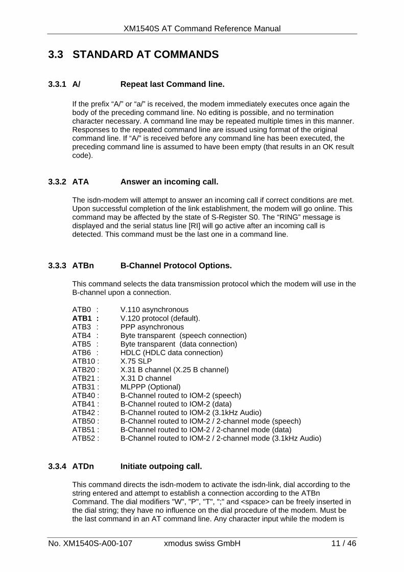
3.3 STANDARD AT COMMANDS 3.3.1 A/ Repeat last Command line.
If the prefix “A/” or “a/” is received, the modem immediately executes once again the body of the preceding command line. No editing is possible, and no termination character necessary. A command line may be repeated multiple times in this manner. Responses to the repeated command line are issued using format of the original command line. If “A/” is received before any command line has been executed, the preceding command line is assumed to have been empty (that results in an OK result code).
3.3.2 ATA Answer an incoming call.
The isdn-modem will attempt to answer an incoming call if correct conditions are met. Upon successful completion of the link establishment, the modem will go online. This command may be affected by the state of S-Register S0. The “RING” message is displayed and the serial status line [RI] will go active after an incoming call is detected. This command must be the last one in a command line.
3.3.3 ATBn B-Channel Protocol Options.
This command selects the data transmission protocol which the modem will use in the B-channel upon a connection. ATB0 : V.110 asynchronous ATB1 : V.120 protocol (default). ATB3 : PPP asynchronous ATB4 : Byte transparent (speech connection) ATB5 : Byte transparent (data connection) ATB6 : HDLC (HDLC data connection) ATB10 : X.75 SLP ATB20 : X.31 B channel (X.25 B channel) ATB21 : X.31 D channel ATB31 : MLPPP (Optional) ATB40 : B-Channel routed to IOM-2 (speech) ATB41 : B-Channel routed to IOM-2 (data) ATB42 : B-Channel routed to IOM-2 (3.1kHz Audio) ATB50 : B-Channel routed to IOM-2 / 2-channel mode (speech) ATB51 : B-Channel routed to IOM-2 / 2-channel mode (data) ATB52 : B-Channel routed to IOM-2 / 2-channel mode (3.1kHz Audio)
3.3.4 ATDn Initiate outpoing call.
This command directs the isdn-modem to activate the isdn-link, dial according to the string entered and attempt to establish a connection according to the ATBn Command. The dial modifiers "W", "P", "T", ";" and <space> can be freely inserted in the dial string; they have no influence on the dial procedure of the modem. Must be the last command in an AT command line. Any character input while the modem is
XM1540S AT Commands Reference Manual
No. XM1540S-A00-107 xmodus swiss GmbH 12 / 46
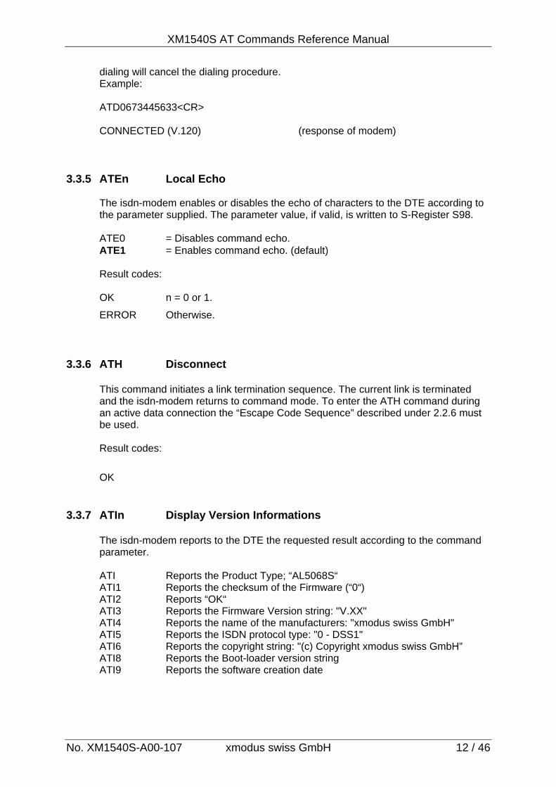
dialing will cancel the dialing procedure. Example: ATD0673445633<CR> CONNECTED (V.120) (response of modem)
3.3.5 ATEn Local Echo
The isdn-modem enables or disables the echo of characters to the DTE according to the parameter supplied. The parameter value, if valid, is written to S-Register S98. ATE0 = Disables command echo. ATE1 = Enables command echo. (default) Result codes: OK n = 0 or 1.
ERROR Otherwise.
3.3.6 ATH Disconnect
This command initiates a link termination sequence. The current link is terminated and the isdn-modem returns to command mode. To enter the ATH command during an active data connection the “Escape Code Sequence” described under 2.2.6 must be used. Result codes:
OK
3.3.7 ATIn Display Version Informations
The isdn-modem reports to the DTE the requested result according to the command parameter.
ATI Reports the Product Type; “AL5068S“ ATI1 Reports the checksum of the Firmware (“0“) ATI2 Reports “OK“ ATI3 Reports the Firmware Version string: "V.XX" ATI4 Reports the name of the manufacturers: "xmodus swiss GmbH" ATI5 Reports the ISDN protocol type: "0 - DSS1" ATI6 Reports the copyright string: "(c) Copyright xmodus swiss GmbH” ATI8 Reports the Boot-loader version string ATI9 Reports the software creation date
XM1540S AT Command Reference Manual
No. XM1540S-A00-107 xmodus swiss GmbH 13 / 46
3.3.8 ATMn - Table of authorized callers
Up to 5 entries may be stored in this table. The ATM command allows the user to store the authorized calling numbers and to report each entry. As many numbers as stored will be compared with the calling number. As example: If “430” is stored , the calling number can be “430” or “4300” or “43033552343” (imagine as wildcard 430*). ATM<n><number><CR> = Stores a new calling number for authorization. n = 0 - 4. number = any caller number. ATM<n>?<CR> = Reports a stored entry. Result codes: EMPTY Entry is empty. <NUMBER> Otherwise.
ATM<n><CR> = Delete entry 3.3.9 ATNn Set V.110 Baudrate
This command selects the terminal baudrate which is used for V.110 B-Channel Protocol. The terminal speed (DTE speed) must be set corresponding (equal) to the
V.110 speed.
ATN3 V.110 baudrate = 4800 bit/s ATN4 V.110 baudrate = 9600 bit/s (default) ATN5 V.110 baudrate = 19200 bit/s
3.3.10 ATO Return to Online State
If the isdn-modem is in the online command mode, entered with the (+++) sequence, this command returns the isdn-modem to Online Data Mode. Handling is determined by the Call Establishment task (see S-Register S96 or ATBn). Generally, if a connection exists, this command connects the DTE back to the remote modem after an escape (+++).Must be the last command in an AT command line. Result codes: OK
3.3.11 ATQn Enable Result Codes
This command enables or disables the sending of result codes to the DTE according to the parameter supplied. The parameter value, if valid, is written to S-Register S32. ATQ0 = Enables result codes to the DTE (default). ATQ1 = Disables result codes to the DTE.
XM1540S AT Commands Reference Manual
No. XM1540S-A00-107 xmodus swiss GmbH 14 / 46
3.3.12 ATSn S-Register Settings
Commands that begin with the letter “S” are known as “S-Parameters”. The number following the “S” indicates the “parameter number “ being referenced. If the number is not recognized as a valid parameter number, an ERROR result code is issued. Immediately following this number, either a “?” or “=” character must appear. “?” is used to read the current value of the indicated S-Parameter; “=” is used to set the S-parameter to a new value. S<parameter_number>? = Read the current value. S<parameter_number>=[value] = Set to [value].
If the “=” is used, the new value to be stored in the S-parameter is specified in decimal following the “=”. If no value is given (i.e., the end of the command line occurs or the next command follows immediately), the S-parameter specified may be set to 0, or an ERROR result code issued and the stored value left unchanged. The ranges of acceptable values are given in the description of each S-parameter. If the “?” is used, the modem transmits a single line of information text to the DTE. The text portion of this information text consists of exactly three characters, giving the value of the S-parameter in decimal, with leading zeroes included.
3.3.13 ATVn Result Code Form
This command selects the sending of short-form or long-form result codes to the DTE. The parameter, if valid, is written to S-Register S42.
ATV0 Enables short-form (terse) result codes. Line feed is not issued before
a short-form result code. ATV1 Enables long-form (verbose) result codes. (Default.) Result is
presented as text (default). 3.3.14 ATWn Enable ISDN Result Codes
This command, in conjunction with AT%Wn and AT%Vn commands can be written directly by the host and control the formats of the extended ISDN messages (see Section 5 and Tables at 5.2). The actual result code messages reported reflect the W command setting and the AT%Wn and AT%Vn settings. The W parameter value, if valid, is written to S45 bits 0 to 3.
ATW0 Result is presented without <xx> and <nr> (default) <xx> = ISDN error cause (see also section 5.2) <nr> = calling party number (see also section 5.2) ATW1 Result is presented with <xx> and <nr> <xx> = ISDN error cause [decimal] (see also section 5.2) <nr> = calling party number (see also section 5.2) ATW2 Result is presented with <xx> and <nr> <xx> = ISDN error cause [text format] (see also section 5.2) <nr> = calling party number (see also section 5.2) ATW3 same as ATW2 but <nr> at CONNECT message is replaced with <datetime> element of L3 frame.
XM1540S AT Command Reference Manual
No. XM1540S-A00-107 xmodus swiss GmbH 15 / 46
3.3.15 ATXn Extented Result Codes
This command selects the subset of the result code messages used by the modem to inform the DTE of the results of commands. The information below is based upon the default implementation of the X results table. Table 5-2 indicates the messages which are enabled for each X value. If the modem is in modem mode, the only message sent to indicate a connection is “CONNECT” without a speed indication. Please see also Chapter 5.
ATX0 CONNECT only (no line speed), send only OK, CONNECT, RING, NO CARRIER and ERROR result codes. ATX1 CONNECT XXXX, send only OK, CONNECT, RING, NO CARRIER,
and ERROR, . If busy tone detection is enforced and busy tone is detected, NO CARRIER will be reported instead of BUSY.
ATX2 CONNECT XXXX, send only OK, CONNECT, RING, NO CARRIER, NO DIALTONE and ERROR. If busy tone detection is enforced and busy tone is detected, NO CARRIER will be reported instead of BUSY ATX3 CONNECT XXXX, Enables reporting of busy tones; send only OK,
CONNECT, RING, NO CARRIER, ERROR, BUSY and NO DIALTONE.
ATX4 CONNECT XXXX, Enables reporting of busy tones; send all messages.
3.3.16 ATZ Load stored settings
The isdn-modem performs a soft reset and restores (recalls) the configuration profile. Must be the last command in an AT command line.
Result codes: OK
XM1540S AT Commands Reference Manual
No. XM1540S-A00-107 xmodus swiss GmbH 16 / 46
3.4 AT& COMMANDS 3.4.1 AT&Cn DCD Options.
The modem controls the DCD output in accordance with the parameter supplied. The parameter value, if valid, is written to S48 bit 0. AT&C0 DCD remains ON at all times. AT&C1 DCD follows the link state and therefore indicates that a connection is
established. (default) 3.4.2 AT&Dn DTR Control
This command interprets the ON to OFF transition of the DTR signal from the DTE in accordance with the parameter supplied. The parameter value, if valid, is written to S47 bits 0 and 1. AT&D0 DTR is ignored (assumed ON). Allows operation with DTE’s which do
not provide DTR. AT&D2 DTR drop causes the modem to hang up. An existing ISDN connection will be terminated. Auto-answer is inhibited when DTR is inactive
(default). AT&D4 DTR drop causes the modem to hang up. An existing ISDN connection will be terminated. Auto-answer is not inhibited when DTR is inactive
3.4.3 AT&Fn Load Factory Defaults
The isdn-modem loads the factory configuration (profile). The factory defaults are identified for each command and in the S-Register descriptions. A configuration (profile) consists of a subset of S-Registers. MSN’s and Phone numbers stored will not be overwritten. AT&F = Restore factory configuration.
3.4.4 AT&Kn Flow Control
This command defines the DTE/DCE (terminal/modem) flow control mechanism. The parameter value, if valid, is written to S39 bits 0, 1, and 2.
AT&K0 Disables flow control.
AT&K3 Enables RTS/CTS flow control. Default for data modem modes.
(default). AT&K5 Enables RTS/CTS flow control in data mode and command mode.
XM1540S AT Command Reference Manual
No. XM1540S-A00-107 xmodus swiss GmbH 17 / 46
3.4.5 AT&Vn Display Current Configuration
This command reports the current (active) configuration, the stored (user) profiles, the MSN numbers and the stored telephone numbers.
AT&V Reports the current (active) configuration.
3.4.6 AT&W Store active Configuration
Saves the current (active) configuration (profile), including S-Registers, in the user profile in NVRAM as denoted by the parameter value. This command will yield an ERROR message if the NVRAM is not installed or it is not operational as detected by the NVRAM test.
The current configuration is comprised of a list of storable parameters illustrated in the &V command. These settings are restored to the active configuration upon receiving an ATZ command or at power up.
AT&W Store the current configuration profile.
Result codes:
OK
XM1540S AT Commands Reference Manual
No. XM1540S-A00-107 xmodus swiss GmbH 18 / 46
3.5 SPECIAL CONFIGURATION COMMANDS 3.5.1 AT%Bn Fixed DTE Baudrate.
This command specifies the data rate at which the modem will accept commands during online operation. It may be used to select operation at rates at which the modem is not capable of automatically detecting the data rate being used by the DTE. Specifying a value of 0 disables the function and allows operation only at rates automatically detectable by the modem. The specified rate takes effect following the issuance of any result code(s) associated with the current command line. Must be the last command in an AT command line. If automatic baudrate detection is enabled, after power-on any messages (i.e. RING) will be send with 115’200bps in the case that no AT command was entered before.
AT%B0 Enables automatic baudrate detection (default). AT%B1 Fixed DTE baudrate = 1200 bit/s AT%B2 Fixed DTE baudrate = 2400 bit/s AT%B3 Fixed DTE baudrate = 4800 bit/s AT%B4 Fixed DTE baudrate = 9600 bit/s AT%B5 Fixed DTE baudrate = 19200 bit/s AT%B6 Fixed DTE baudrate = 38400 bit/s AT%B7 Fixed DTE baudrate = 57600 bit/s AT%B8 Fixed DTE baudrate = 115200 bit/s AT%B9 Fixed DTE baudrate = 230400 bit/s
3.5.2 AT%R Automatic reboot
This command allows to make the modem rebooting automatically after each disconnect. Format: AT%R=n (for n = 0…255). If n >0, after n seconds the modem will be rebooted (reset) after each disconnect (hangup). The modem should be left idle after a disconnect to let the reboot take place.
3.5.3 AT%Wn Message compatibility modes. Sets the compatibilty of the result messages (see chapter 5) AT%W0 AL5068S Message Mode. AT%W1 AL5064S Message Mode (default). AT%W2 Modem Message Mode.
3.5.4 AT%Vn CONNECT message formats. Sets the formats of the CONNECT message (see also chapter 5) AT%V0 CONNECT only. AT%V1 CONNECT (B-Channel protocol) (default) AT%V2 CONNECT <Line-speed> (B-Channel protocol)
XM1540S AT Command Reference Manual
No. XM1540S-A00-107 xmodus swiss GmbH 19 / 46
3.5.5 AT**DBITS DTE Character Format (Data Bits) This command select the number of data bits of the terminal (DTE) asynchronous character format. 7 or 8 bits / character can be selected. AT**DBITS=7 Selects 7 bits character format. AT**DBITS=8 Selects 8 bits character format (default).
3.5.6 AT**PRTY DTE Character Format (Parity)
This command select the parity type of the terminal (DTE) asynchronous character format. Even, Odd or no parity can be selected. AT**PRTY=0 Select no parity (default) AT**PRTY=1 Select Even parity AT**PRTY=2 Select Odd parity
3.6 ISDN SERVICES COMMANDS 3.6.1 AT$M Report CLID (Received Called Line ID)
Reports the CLID (called line identification) that is received upon an incoming call. The CLID is the number of the called party addressed on the local S-bus.
3.6.2 AT$O Report CLIP (Received Calling Party)
Reports the CLIP (calling line identification) that is received upon an incoming call. The CLIP is the number of the calling party.
3.6.3 AT$Pn Define X.3 Parameters
Defines the X.3 International Parameters. For detailed description see chapter 7. AT$Pn=x Defines X.3 parameter n with value x AT$P? Shows the X.3 Parameters with their values.
3.6.4 AT$Z Define Own MSN Defines the msn nn (multiple subscriber number) for the data port. If the number is set to “*“ (default), all incoming calls are acceptable. The msn can be displayed by command AT&V. AT$Z=nn set parameter "msni" and "msno" to nn
XM1540S AT Commands Reference Manual
No. XM1540S-A00-107 xmodus swiss GmbH 20 / 46
3.7 ISDN CONFIGURATION COMMANDS 3.7.1 AT**BSIZE Selects B-Channel Packet Size
This command selects the maximum length of a data block in the X.31 and/or V.120 B-Channel protocols. This parameter will be changed by the setting of other B-Channel protocols (ATBn). AT**BSIZE=64 Selects a block length of 64 bytes AT**BSIZE=128 Selects a block length of 128 bytes AT**BSIZE=256 Selects a block length of 256 bytes (default) AT**BSIZE=512 Selects a block length of 512 bytes AT**BSIZE=1024 Selects a block length of 1014 bytes AT**BSIZE=2048 Selects a block length of 2048 bytes
3.7.2 AT**DTE Selects B-Channel Layer 2 Address
This command selects the Layer 2 link address used for X.25-B protocol. . This parameter will be changed by the setting of other B-Channel protocols (ATBn). AT**DTE=0 Calling side = DTE; Called side = DCE
AT**DTE=1 Reacts as DTE (address = 01) (default) AT**DTE=3 Reacts as DCE (address = 03)
3.7.3 AT**K X.75 / V.120 Window Size The isdn-modem will operate an X.75 or V.120 error corrected link using a window size controlled by the parameter supplied. A window size from 1 – 7 can be supplied. The value of 1 is chosen for compatibility with other products. A value of 2 – 7 should be chosen for best performance (default = 7). AT**K=n n = 1 – 7 , default = 7
XM1540S AT Command Reference Manual
No. XM1540S-A00-107 xmodus swiss GmbH 21 / 46
4. S-REGISTERS
The S-Registers are summarized in Table 4-1 along with their default values; registers denoted with an “*” are stored in the user profile by entering the AT&W command. These profile may be loaded at any time by using the ATZ command.
4.1 ATSn Read / Write S-Register
The isdn-modem selects an S-Register, performs an S-Register read or write function, or reports the value of an S-Register. n=v = Sets S-Register n to the value v. n? = Reports the value of S-Register n. If the number “n” is beyond the range of the S-Registers available, the modem will return the ERROR message. The value “v” is “MOD”ed with 256. If the result is outside the range permitted for a given S-Register the values will still be stored, but functionally the lower and higher limits will be observed. Input and output are always in decimal format. Note that some S-Registers are read-only. In some cases, writing to the S-Registers will appear to be accepted but the value will not actually be written.
4.2 FACTORY DEFAULTS
The factory default values are stored in ROM and are loaded into the active configuration at power up or by the ATZ command. In addition, the designated default profile (stored by AT&W) is subsequently loaded, and may change some of the factory default values. The defaults shown are those used by xmodus as the factory profile. The default values shown in Table 4-1 may vary by modem firmware configuration. Consult the MCU firmware release notes for exact configuration. The factory default values may be loaded at any time by entering the AT&F command.
XM1540S AT Commands Reference Manual
No. XM1540S-A00-107 xmodus swiss GmbH 22 / 46
4.3 S-REGISTER SUMMARY
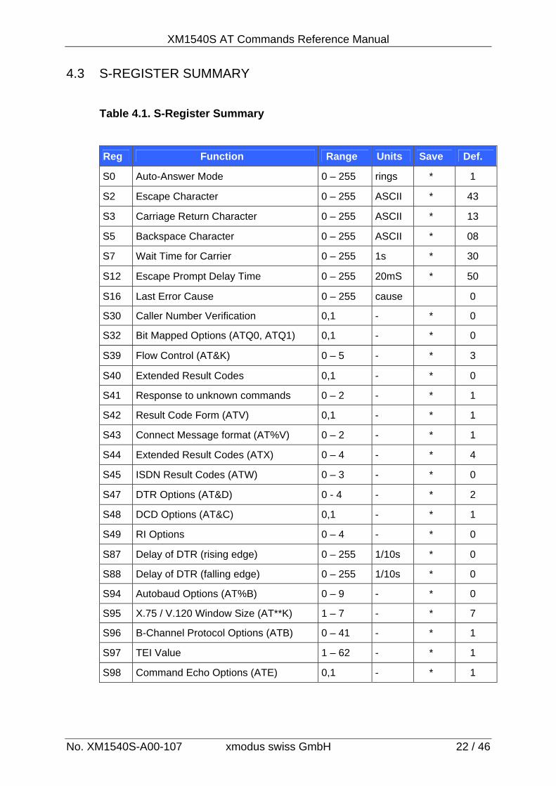
Table 4.1. S-Register Summary
Reg Function Range Units Save Def.
S0 Auto-Answer Mode 0 – 255 rings * 1
S2 Escape Character 0 – 255 ASCII * 43
S3 Carriage Return Character 0 – 255 ASCII * 13
S5 Backspace Character 0 – 255 ASCII * 08
S7 Wait Time for Carrier 0 – 255 1s * 30
S12 Escape Prompt Delay Time 0 – 255 20mS * 50
S16 Last Error Cause 0 – 255 cause 0
S30 Caller Number Verification 0,1 - * 0
S32 Bit Mapped Options (ATQ0, ATQ1) 0,1 - * 0
S39 Flow Control (AT&K) 0 – 5 - * 3
S40 Extended Result Codes 0,1 - * 0
S41 Response to unknown commands 0 – 2 - * 1
S42 Result Code Form (ATV) 0,1 - * 1
S43 Connect Message format (AT%V) 0 – 2 - * 1
S44 Extended Result Codes (ATX) 0 – 4 - * 4
S45 ISDN Result Codes (ATW) 0 – 3 - * 0
S47 DTR Options (AT&D) 0 - 4 - * 2
S48 DCD Options (AT&C) 0,1 - * 1
S49 RI Options 0 – 4 - * 0
S87 Delay of DTR (rising edge) 0 – 255 1/10s * 0
S88 Delay of DTR (falling edge) 0 – 255 1/10s * 0
S94 Autobaud Options (AT%B) 0 – 9 - * 0
S95 X.75 / V.120 Window Size (AT**K) 1 – 7 - * 7
S96 B-Channel Protocol Options (ATB) 0 – 41 - * 1
S97 TEI Value 1 – 62 - * 1
S98 Command Echo Options (ATE) 0,1 - * 1
XM1540S AT Command Reference Manual
No. XM1540S-A00-107 xmodus swiss GmbH 23 / 46
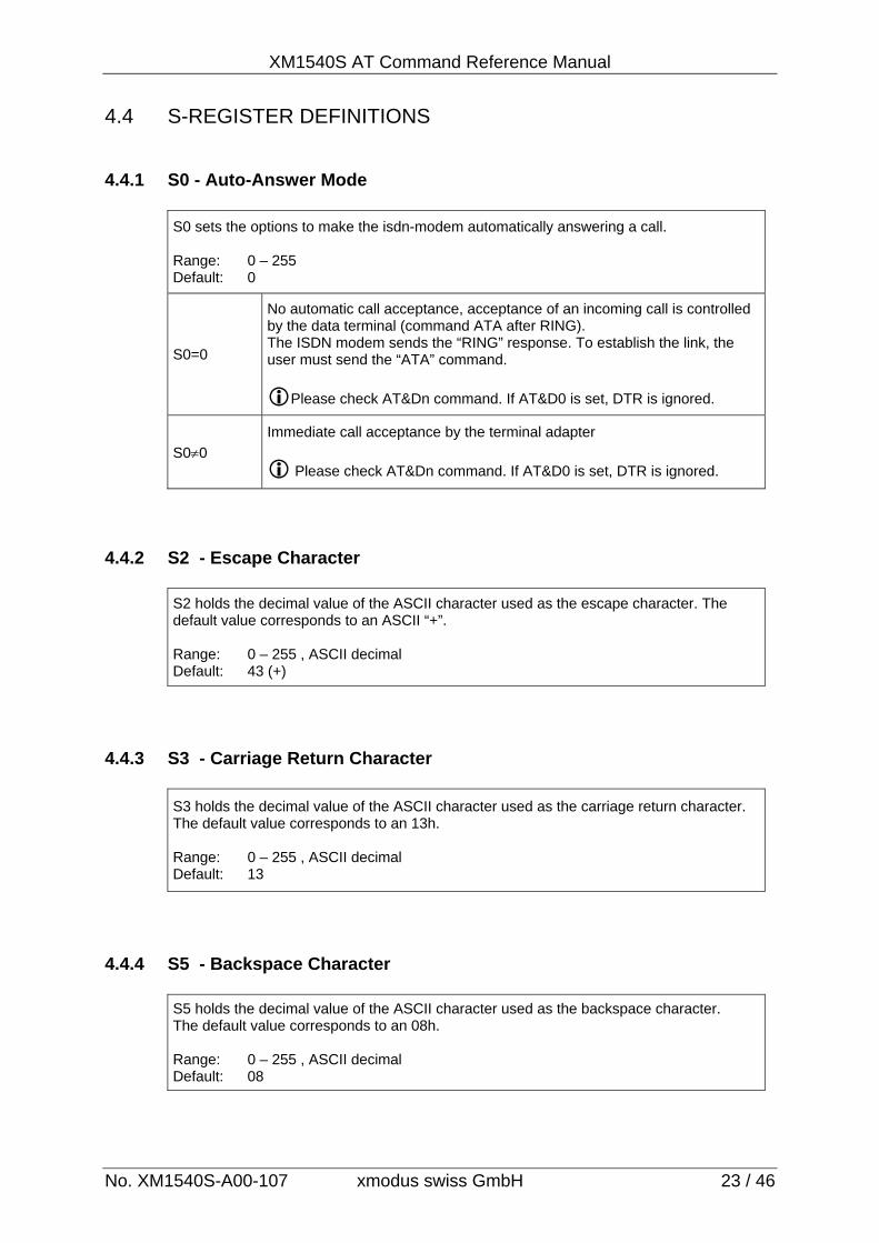
4.4 S-REGISTER DEFINITIONS 4.4.1 S0 - Auto-Answer Mode
S0 sets the options to make the isdn-modem automatically answering a call. Range: 0 – 255 Default: 0
S0=0
No automatic call acceptance, acceptance of an incoming call is controlled by the data terminal (command ATA after RING). The ISDN modem sends the “RING” response. To establish the link, the user must send the “ATA” command.
Please check AT&Dn command. If AT&D0 is set, DTR is ignored.
S00
Immediate call acceptance by the terminal adapter
Please check AT&Dn command. If AT&D0 is set, DTR is ignored.
4.4.2 S2 - Escape Character
S2 holds the decimal value of the ASCII character used as the escape character. The default value corresponds to an ASCII “+”. Range: 0 – 255 , ASCII decimal Default: 43 (+)
4.4.3 S3 - Carriage Return Character
S3 holds the decimal value of the ASCII character used as the carriage return character. The default value corresponds to an 13h. Range: 0 – 255 , ASCII decimal Default: 13
4.4.4 S5 - Backspace Character
S5 holds the decimal value of the ASCII character used as the backspace character. The default value corresponds to an 08h. Range: 0 – 255 , ASCII decimal Default: 08
XM1540S AT Commands Reference Manual
No. XM1540S-A00-107 xmodus swiss GmbH 24 / 46
4.4.5 S7 - Wait Time for Carrier
No function. Only for compatibilty.
4.4.6 S12 - Escape Prompt Delay Time
S12 defines the maximum period, in 20ms units, allowed between receipt of the last character of the three escape character sequence from the DTE and sending of the OK result code to the DTE. If any characters are detected during this time, the OK will not be sent. Range: 0 – 255 Default: 50
4.4.7 S16 - Last Error Cause
Last occurred ISDN error cause
4.4.8 S30 - Caller Number Verification
S30 controls the Caller Number Verification in Auto-Answer Mode. See also ATMn Command. Range: 0,1 (Bit Mapped) Default: 0
S30=0 Caller Number Verification is disabled (OFF). All calls from remote modems are allowed and will be accepted.
S300
The caller number will be verified at an incoming call. A call is only accepted, if the caller number is registered in the table of Authorized Caller Numbers (see ATM command). Otherwise the incoming call is denied.
4.4.9 S32 - Bit Mapped Options (ATQn Command)
S32 sets the options of ATQn command. Range: 0,1 (Bit Mapped) Default: 0
S32=0 Enables result codes to the DTE.
S320 Disables result codes to the DTE.
XM1540S AT Command Reference Manual
No. XM1540S-A00-107 xmodus swiss GmbH 25 / 46
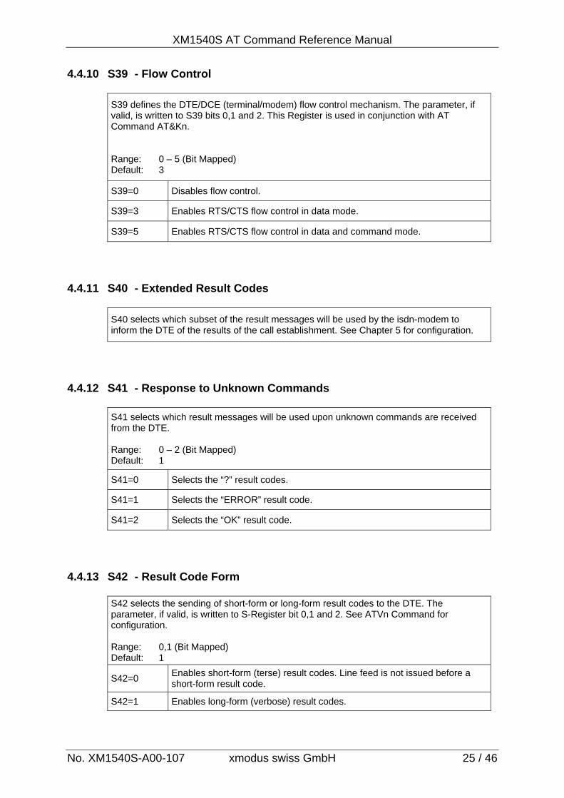
4.4.10 S39 - Flow Control
S39 defines the DTE/DCE (terminal/modem) flow control mechanism. The parameter, if valid, is written to S39 bits 0,1 and 2. This Register is used in conjunction with AT Command AT&Kn. Range: 0 – 5 (Bit Mapped) Default: 3
S39=0 Disables flow control.
S39=3 Enables RTS/CTS flow control in data mode.
S39=5 Enables RTS/CTS flow control in data and command mode.
4.4.11 S40 - Extended Result Codes
S40 selects which subset of the result messages will be used by the isdn-modem to inform the DTE of the results of the call establishment. See Chapter 5 for configuration.
4.4.12 S41 - Response to Unknown Commands
S41 selects which result messages will be used upon unknown commands are received from the DTE. Range: 0 – 2 (Bit Mapped) Default: 1
S41=0 Selects the “?” result codes.
S41=1 Selects the “ERROR” result code.
S41=2 Selects the “OK” result code.
4.4.13 S42 - Result Code Form
S42 selects the sending of short-form or long-form result codes to the DTE. The parameter, if valid, is written to S-Register bit 0,1 and 2. See ATVn Command for configuration. Range: 0,1 (Bit Mapped) Default: 1
S42=0 Enables short-form (terse) result codes. Line feed is not issued before a short-form result code.
S42=1 Enables long-form (verbose) result codes.
XM1540S AT Commands Reference Manual
No. XM1540S-A00-107 xmodus swiss GmbH 26 / 46
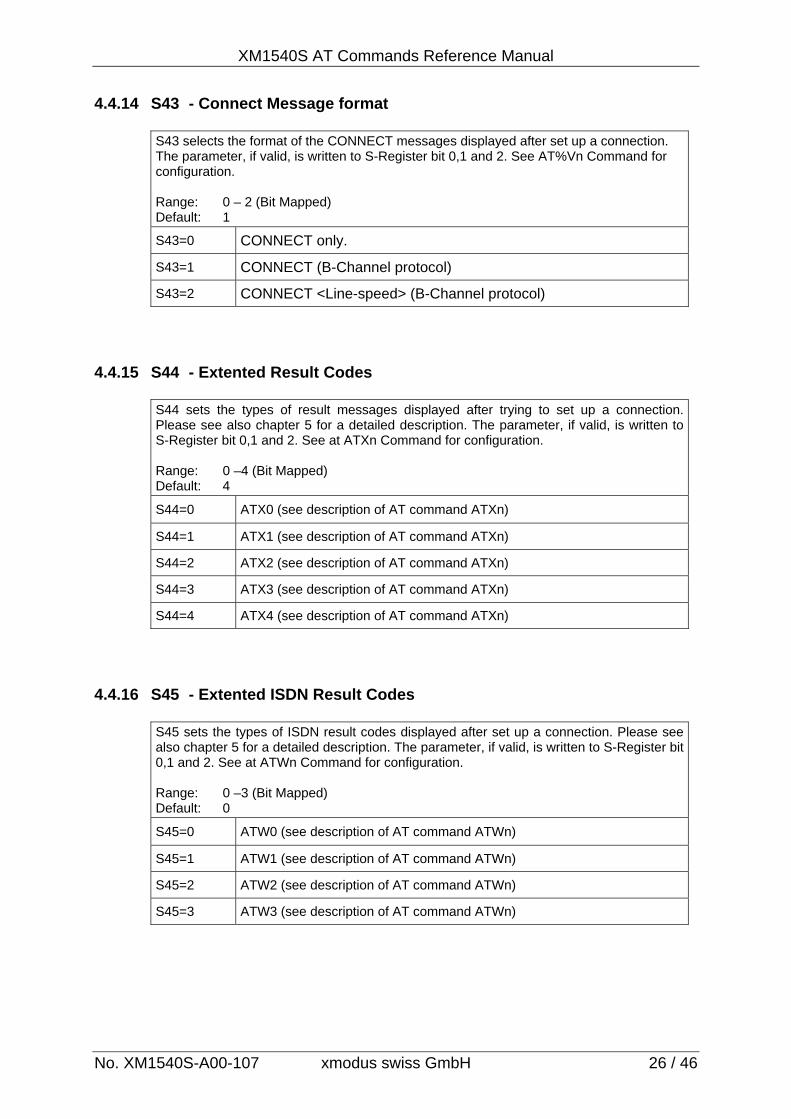
4.4.14 S43 - Connect Message format
S43 selects the format of the CONNECT messages displayed after set up a connection. The parameter, if valid, is written to S-Register bit 0,1 and 2. See AT%Vn Command for configuration. Range: 0 – 2 (Bit Mapped) Default: 1
S43=0 CONNECT only.
S43=1 CONNECT (B-Channel protocol)
S43=2 CONNECT <Line-speed> (B-Channel protocol)
4.4.15 S44 - Extented Result Codes
S44 sets the types of result messages displayed after trying to set up a connection. Please see also chapter 5 for a detailed description. The parameter, if valid, is written to S-Register bit 0,1 and 2. See at ATXn Command for configuration. Range: 0 –4 (Bit Mapped) Default: 4
S44=0 ATX0 (see description of AT command ATXn)
S44=1 ATX1 (see description of AT command ATXn)
S44=2 ATX2 (see description of AT command ATXn)
S44=3 ATX3 (see description of AT command ATXn)
S44=4 ATX4 (see description of AT command ATXn)
4.4.16 S45 - Extented ISDN Result Codes
S45 sets the types of ISDN result codes displayed after set up a connection. Please see also chapter 5 for a detailed description. The parameter, if valid, is written to S-Register bit 0,1 and 2. See at ATWn Command for configuration. Range: 0 –3 (Bit Mapped) Default: 0
S45=0 ATW0 (see description of AT command ATWn)
S45=1 ATW1 (see description of AT command ATWn)
S45=2 ATW2 (see description of AT command ATWn)
S45=3 ATW3 (see description of AT command ATWn)
XM1540S AT Command Reference Manual
No. XM1540S-A00-107 xmodus swiss GmbH 27 / 46
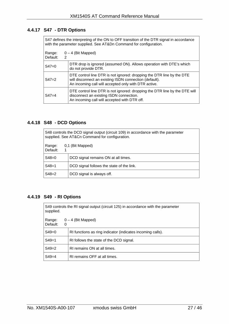
4.4.17 S47 - DTR Options
S47 defines the interpreting of the ON to OFF transition of the DTR signal in accordance with the parameter supplied. See AT&Dn Command for configuration. Range: 0 – 4 (Bit Mapped) Default: 2
S47=0 DTR drop is ignored (assumed ON). Allows operation with DTE’s which do not provide DTR.
S47=2 DTE control line DTR is not ignored: dropping the DTR line by the DTE will disconnect an existing ISDN connection (default). An incoming call will accepted only with DTR active.
S47=4 DTE control line DTR is not ignored: dropping the DTR line by the DTE will disconnect an existing ISDN connection. An incoming call will accepted with DTR off.
4.4.18 S48 - DCD Options
S48 controls the DCD signal output (circuit 109) in accordance with the parameter supplied. See AT&Cn Command for configuration. Range: 0,1 (Bit Mapped) Default: 1
S48=0 DCD signal remains ON at all times.
S48=1 DCD signal follows the state of the link.
S48=2 DCD signal is always off.
4.4.19 S49 - RI Options
S49 controls the RI signal output (circuit 125) in accordance with the parameter supplied. Range: 0 – 4 (Bit Mapped) Default: 0
S49=0 RI functions as ring indicator (indicates incoming calls).
S49=1 RI follows the state of the DCD signal.
S49=2 RI remains ON at all times.
S49=4 RI remains OFF at all times.
XM1540S AT Commands Reference Manual
No. XM1540S-A00-107 xmodus swiss GmbH 28 / 46
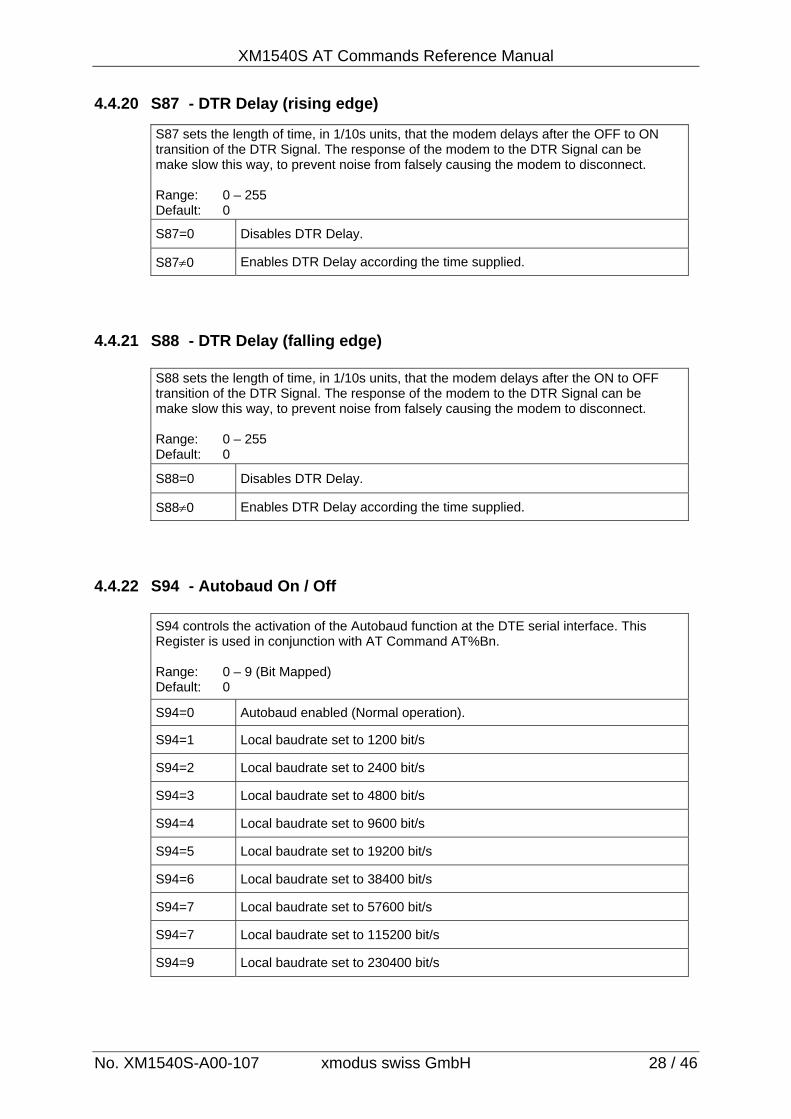
4.4.20 S87 - DTR Delay (rising edge)
S87 sets the length of time, in 1/10s units, that the modem delays after the OFF to ON transition of the DTR Signal. The response of the modem to the DTR Signal can be make slow this way, to prevent noise from falsely causing the modem to disconnect. Range: 0 – 255 Default: 0
S87=0 Disables DTR Delay.
S870 Enables DTR Delay according the time supplied.
4.4.21 S88 - DTR Delay (falling edge)
S88 sets the length of time, in 1/10s units, that the modem delays after the ON to OFF transition of the DTR Signal. The response of the modem to the DTR Signal can be make slow this way, to prevent noise from falsely causing the modem to disconnect. Range: 0 – 255 Default: 0
S88=0 Disables DTR Delay.
S880 Enables DTR Delay according the time supplied.
4.4.22 S94 - Autobaud On / Off
S94 controls the activation of the Autobaud function at the DTE serial interface. This Register is used in conjunction with AT Command AT%Bn. Range: 0 – 9 (Bit Mapped) Default: 0
S94=0 Autobaud enabled (Normal operation).
S94=1 Local baudrate set to 1200 bit/s
S94=2 Local baudrate set to 2400 bit/s
S94=3 Local baudrate set to 4800 bit/s
S94=4 Local baudrate set to 9600 bit/s
S94=5 Local baudrate set to 19200 bit/s
S94=6 Local baudrate set to 38400 bit/s
S94=7 Local baudrate set to 57600 bit/s
S94=7 Local baudrate set to 115200 bit/s
S94=9 Local baudrate set to 230400 bit/s
XM1540S AT Command Reference Manual
No. XM1540S-A00-107 xmodus swiss GmbH 29 / 46
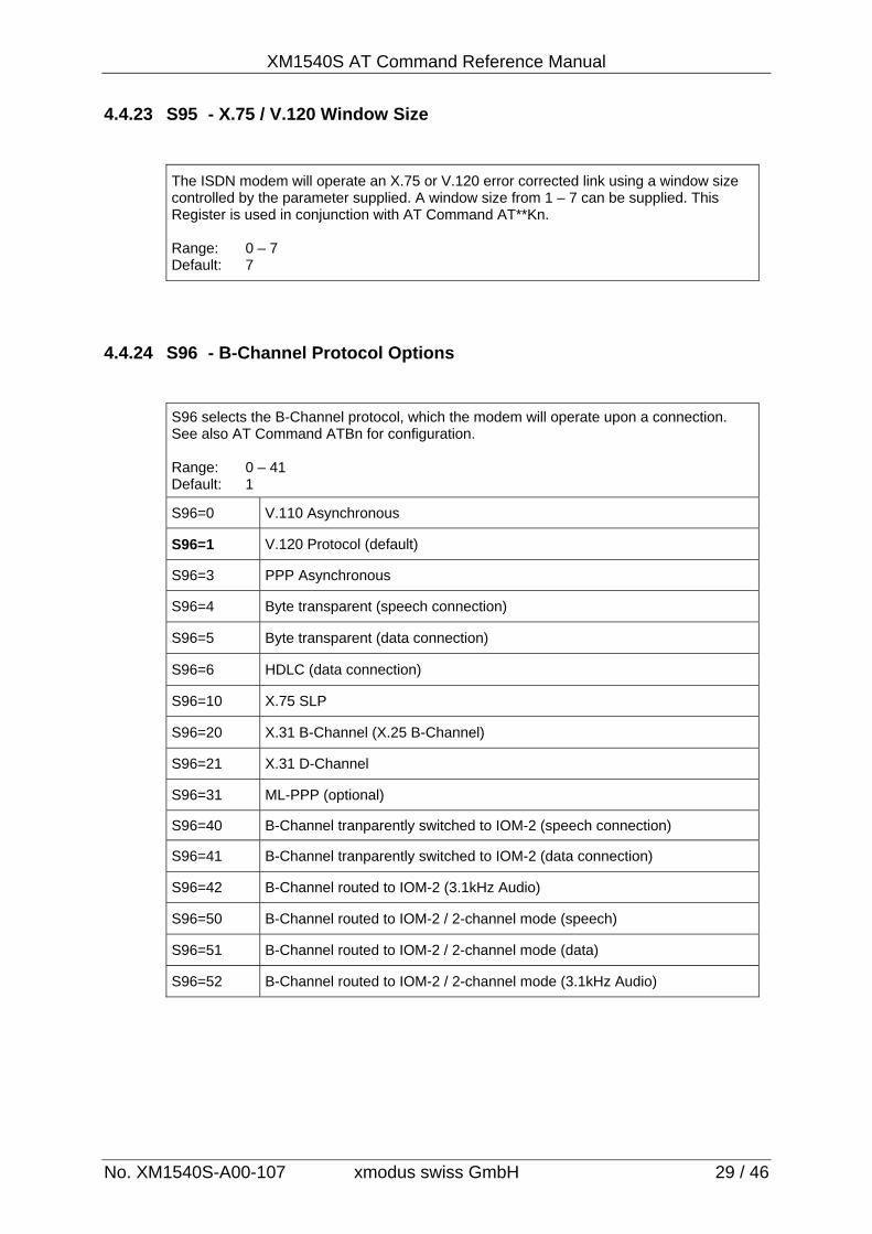
4.4.23 S95 - X.75 / V.120 Window Size
The ISDN modem will operate an X.75 or V.120 error corrected link using a window size controlled by the parameter supplied. A window size from 1 – 7 can be supplied. This Register is used in conjunction with AT Command AT**Kn. Range: 0 – 7 Default: 7
4.4.24 S96 - B-Channel Protocol Options
S96 selects the B-Channel protocol, which the modem will operate upon a connection. See also AT Command ATBn for configuration. Range: 0 – 41 Default: 1
S96=0 V.110 Asynchronous
S96=1 V.120 Protocol (default)
S96=3 PPP Asynchronous
S96=4 Byte transparent (speech connection)
S96=5 Byte transparent (data connection)
S96=6 HDLC (data connection)
S96=10 X.75 SLP
S96=20 X.31 B-Channel (X.25 B-Channel)
S96=21 X.31 D-Channel
S96=31 ML-PPP (optional)
S96=40 B-Channel tranparently switched to IOM-2 (speech connection)
S96=41 B-Channel tranparently switched to IOM-2 (data connection)
S96=42 B-Channel routed to IOM-2 (3.1kHz Audio)
S96=50 B-Channel routed to IOM-2 / 2-channel mode (speech)
S96=51 B-Channel routed to IOM-2 / 2-channel mode (data)
S96=52 B-Channel routed to IOM-2 / 2-channel mode (3.1kHz Audio)
XM1540S AT Commands Reference Manual
No. XM1540S-A00-107 xmodus swiss GmbH 30 / 46
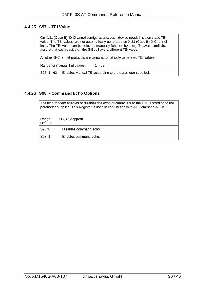
4.4.25 S97 - TEI Value
On X.31 (Case B) D-Channel configurations, each device needs his own static TEI value. The TEI values are not automatically generated on X.31 (Case B) D-Channel links. The TEI value can be selected manually (chosen by user). To avoid conflicts, assure that each device on the S-Bus have a different TEI value. All other B-Channel protocols are using automatically generated TEI values. Range for manual TEI values: 1 – 62
S97=1– 62 Enables Manual TEI according to the parameter supplied.
4.4.26 S98 - Command Echo Options
The isdn-modem enables or disables the echo of characters to the DTE according to the parameter supplied. This Register is used in conjunction with AT Command ATEn. Range: 0,1 (Bit Mapped) Default: 1
S98=0 Disables command echo.
S98=1 Enables command echo.
XM1540S AT Command Reference Manual
No. XM1540S-A00-107 xmodus swiss GmbH 31 / 46
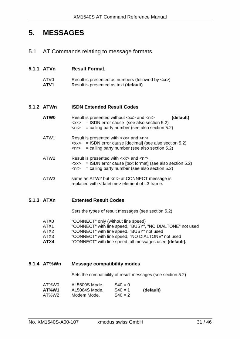
5. MESSAGES 5.1 AT Commands relating to message formats. 5.1.1 ATVn Result Format. ATV0 Result is presented as numbers (followed by <cr>) ATV1 Result is presented as text (default) 5.1.2 ATWn ISDN Extended Result Codes ATW0 Result is presented without <xx> and <nr> (default) <xx> = ISDN error cause (see also section 5.2) <nr> = calling party number (see also section 5.2) ATW1 Result is presented with <xx> and <nr> <xx> = ISDN error cause [decimal] (see also section 5.2) <nr> = calling party number (see also section 5.2) ATW2 Result is presented with <xx> and <nr> <xx> = ISDN error cause [text format] (see also section 5.2) <nr> = calling party number (see also section 5.2) ATW3 same as ATW2 but <nr> at CONNECT message is replaced with <datetime> element of L3 frame. 5.1.3 ATXn Extented Result Codes
Sets the types of result messages (see section 5.2) ATX0 "CONNECT" only (without line speed) ATX1 "CONNECT" with line speed, "BUSY", "NO DIALTONE" not used ATX2 "CONNECT" with line speed, "BUSY" not used ATX3 "CONNECT" with line speed, "NO DIALTONE" not used ATX4 "CONNECT" with line speed, all messages used (default).
5.1.4 AT%Wn Message compatibility modes
Sets the compatibility of result messages (see section 5.2) AT%W0 AL5500S Mode. S40 = 0 AT%W1 AL5064S Mode. S40 = 1 (default) AT%W2 Modem Mode. S40 = 2
XM1540S AT Commands Reference Manual
No. XM1540S-A00-107 xmodus swiss GmbH 32 / 46
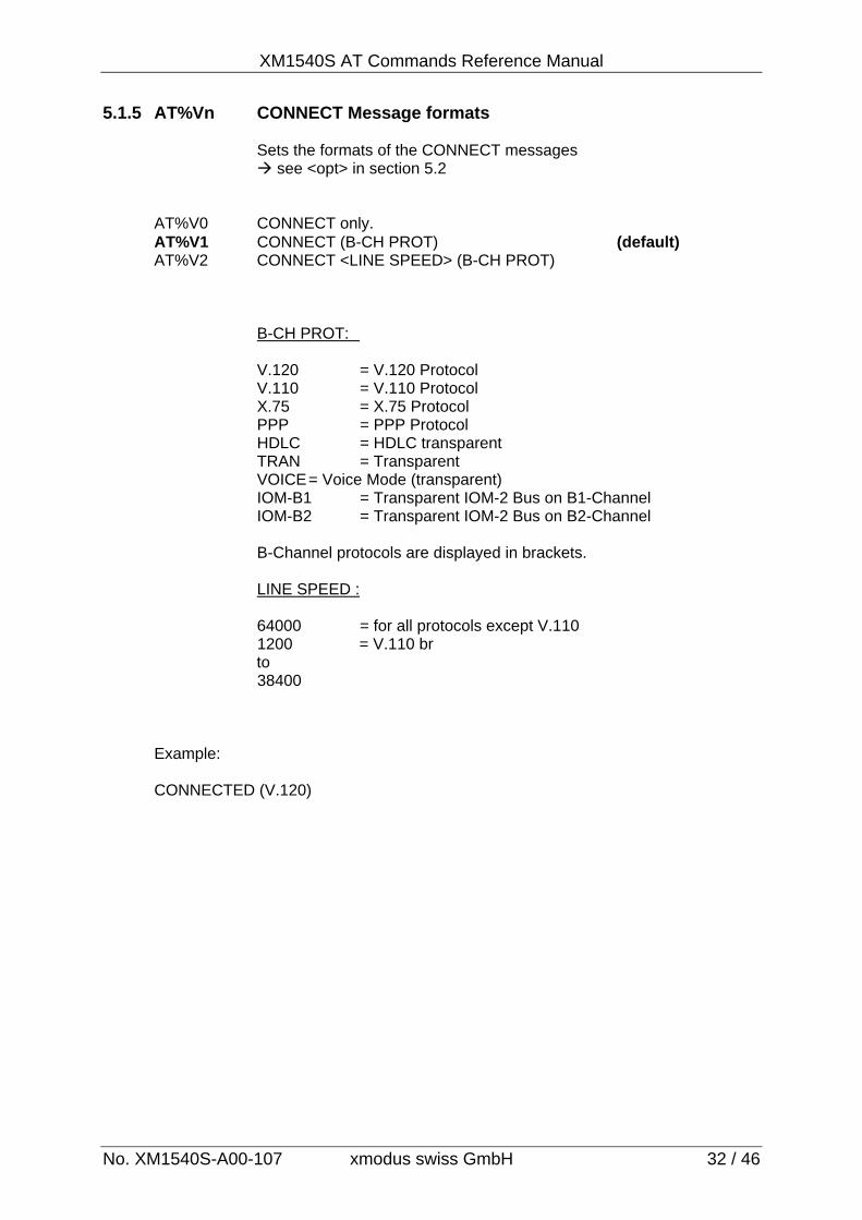
5.1.5 AT%Vn CONNECT Message formats Sets the formats of the CONNECT messages see <opt> in section 5.2 AT%V0 CONNECT only. AT%V1 CONNECT (B-CH PROT) (default) AT%V2 CONNECT <LINE SPEED> (B-CH PROT)
B-CH PROT: V.120 = V.120 Protocol V.110 = V.110 Protocol X.75 = X.75 Protocol PPP = PPP Protocol HDLC = HDLC transparent TRAN = Transparent VOICE = Voice Mode (transparent) IOM-B1 = Transparent IOM-2 Bus on B1-Channel IOM-B2 = Transparent IOM-2 Bus on B2-Channel B-Channel protocols are displayed in brackets. LINE SPEED : 64000 = for all protocols except V.110
1200 = V.110 br to 38400
Example: CONNECTED (V.120)
XM1540S AT Command Reference Manual
No. XM1540S-A00-107 xmodus swiss GmbH 33 / 46
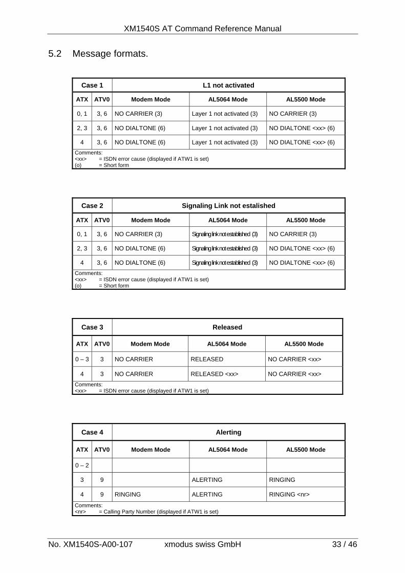
5.2 Message formats.
Case 1 L1 not activated
ATX ATV0 Modem Mode AL5064 Mode AL5500 Mode
0, 1 3, 6 NO CARRIER (3) Layer 1 not activated (3) NO CARRIER (3)
2, 3 3, 6 NO DIALTONE (6) Layer 1 not activated (3) NO DIALTONE <xx> (6)
4 3, 6 NO DIALTONE (6) Layer 1 not activated (3) NO DIALTONE <xx> (6)
Comments: <xx> = ISDN error cause (displayed if ATW1 is set) (o) = Short form
Case 2 Signaling Link not estalished
ATX ATV0 Modem Mode AL5064 Mode AL5500 Mode
0, 1 3, 6 NO CARRIER (3) Signaling link not established (3) NO CARRIER (3)
2, 3 3, 6 NO DIALTONE (6) Signaling link not established (3) NO DIALTONE <xx> (6)
4 3, 6 NO DIALTONE (6) Signaling link not established (3) NO DIALTONE <xx> (6)
Comments: <xx> = ISDN error cause (displayed if ATW1 is set) (o) = Short form
Case 3 Released
ATX ATV0 Modem Mode AL5064 Mode AL5500 Mode
0 – 3 3 NO CARRIER RELEASED NO CARRIER <xx>
4 3 NO CARRIER RELEASED <xx> NO CARRIER <xx>
Comments: <xx> = ISDN error cause (displayed if ATW1 is set)
Case 4 Alerting
ATX ATV0 Modem Mode AL5064 Mode AL5500 Mode
0 – 2
3 9 ALERTING RINGING
4 9 RINGING ALERTING RINGING <nr>
Comments: <nr> = Calling Party Number (displayed if ATW1 is set)
XM1540S AT Commands Reference Manual
No. XM1540S-A00-107 xmodus swiss GmbH 34 / 46
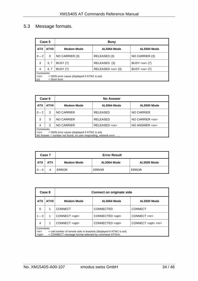
5.3 Message formats.
Case 5 Busy
ATX ATV0 Modem Mode AL5064 Mode AL5500 Mode
0 – 2 3 NO CARRIER (3) RELEASED (3) NO CARRIER (3)
3 3, 7 BUSY (7) RELEASED (3) BUSY <xx> (7)
4 3, 7 BUSY (7) RELEASED <xx> (3) BUSY <xx> (7) Comments: <xx> = ISDN error cause (displayed if ATW1 is set) (o) = Short form
Case 6 No Answer
ATX ATV0 Modem Mode AL5064 Mode AL5500 Mode
0 – 2 3 NO CARRIER RELEASED NO CARRIER
3 3 NO CARRIER RELEASED NO CARRIER <xx>
4 3 NO CARRIER RELEASED <xx> NO ANSWER <xx> Comments: <xx> = ISDN error cause (displayed if ATW1 is set) No Answer = number not found, no user responding, network error …..
Case 7 Error Result
ATX ATV Modem Mode AL5064 Mode AL5500 Mode
0 – 4 4 ERROR ERROR ERROR
Case 8 Connect on originate side
ATX ATV0 Modem Mode AL5064 Mode AL5500 Mode
0 1 CONNECT CONNECTED CONNECT
1 – 3 1 CONNECT <opt> CONNECTED <opt> CONNECT <nr>
4 1 CONNECT <opt> CONNECTED <opt> CONNECT <opt> <nr>
Comments: <nr> = call number of remote side in brackets (displayed if ATW1 is set) <opt> = CONNECT message format selected by command AT%Vn.
XM1540S AT Command Reference Manual
No. XM1540S-A00-107 xmodus swiss GmbH 35 / 46
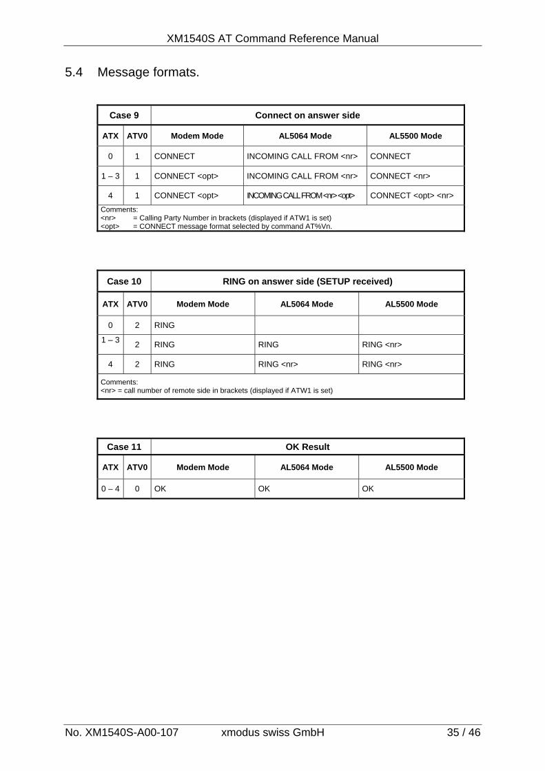
5.4 Message formats.
Case 9 Connect on answer side
ATX ATV0 Modem Mode AL5064 Mode AL5500 Mode
0 1 CONNECT INCOMING CALL FROM <nr> CONNECT
1 – 3 1 CONNECT <opt> INCOMING CALL FROM <nr> CONNECT <nr>
4 1 CONNECT <opt> INCOMING CALL FROM <nr> <opt> CONNECT <opt> <nr>
Comments: <nr> = Calling Party Number in brackets (displayed if ATW1 is set) <opt> = CONNECT message format selected by command AT%Vn.
Case 10 RING on answer side (SETUP received)
ATX ATV0 Modem Mode AL5064 Mode AL5500 Mode
0 2 RING
1 – 3
2 RING RING RING <nr>
4 2 RING RING <nr> RING <nr>
Comments: <nr> = call number of remote side in brackets (displayed if ATW1 is set)
Case 11 OK Result
ATX ATV0 Modem Mode AL5064 Mode AL5500 Mode
0 – 4 0 OK OK OK
XM1540S AT Commands Reference Manual
No. XM1540S-A00-107 xmodus swiss GmbH 36 / 46
5.5 CALLING NUMBER REPORT (CLIP)
The CLIP (calling party number) can be reported together with the “CONNECTED” or the “RING” messages. To enable this, ATW1 or ATW2 must be selected (see description at 3.3.14). The CLIP can be reported also by issuing the command AT$O. This way, only the CLIP number is reported. If the ISDN Modem is used at the public network, then the full call number of the remote site (including area code) is reported. Example: ATW1 send to modem
OK received from modem RING 0448903322 received from modem ATA send to modem CONNECTED (V.120) 0448903322 received from modem
5.6 ISDN ERROR CAUSE REPORT
The ISDN error causes can be reported together with the “RELEASED” or “NO CARRIER” message. If ATW1 is selected, the error causes are reported in decimal form. If ATW2 is selected, the error causes are reported in text format. The coding scheme is as per ETSI definition. Example 1: ATW1 send to modem
OK received from modem ATD0449121234 send to modem RELEASED 17 received from modem Example 2: ATW2 send to modem
OK received from modem ATD0449121234 send to modem RELEASED USER BUSY received from modem
XM1540S AT Command Reference Manual
No. XM1540S-A00-107 xmodus swiss GmbH 37 / 46
6. X.31 CALL SETUP 6.1 Setup outgoing X.31 call
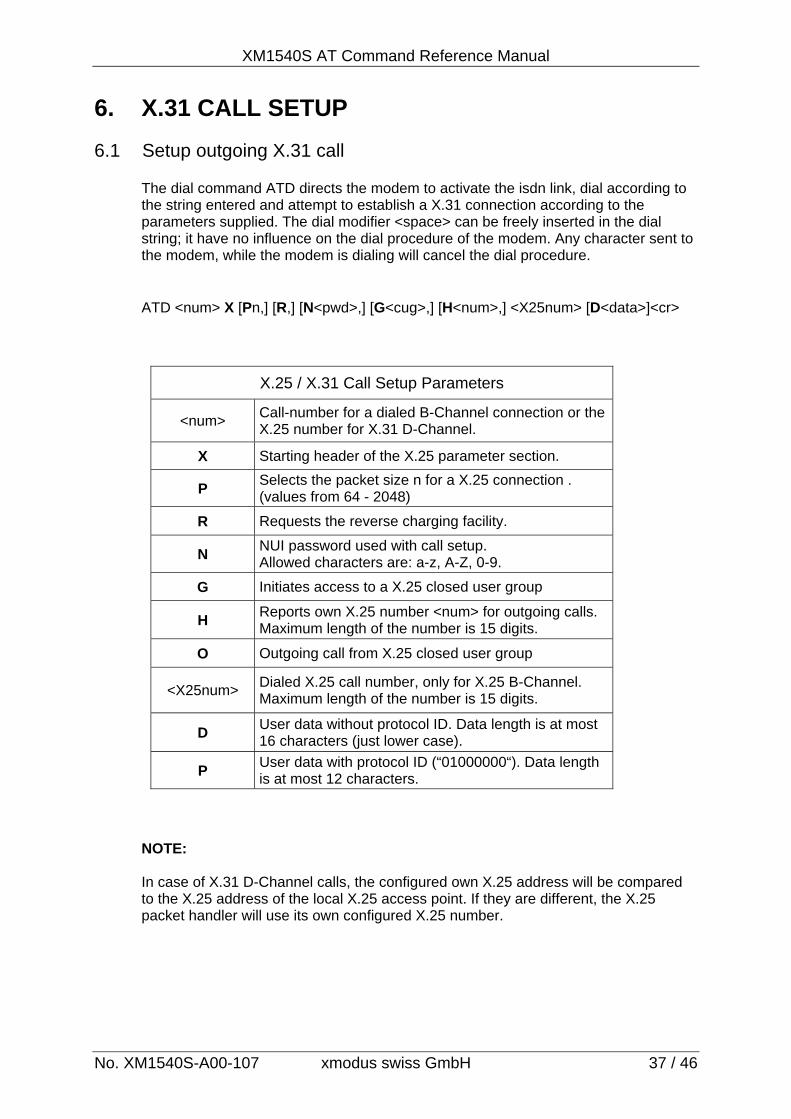
The dial command ATD directs the modem to activate the isdn link, dial according to the string entered and attempt to establish a X.31 connection according to the parameters supplied. The dial modifier <space> can be freely inserted in the dial string; it have no influence on the dial procedure of the modem. Any character sent to the modem, while the modem is dialing will cancel the dial procedure. ATD <num> X [Pn,] [R,] [N<pwd>,] [G<cug>,] [H<num>,] <X25num> [D<data>]<cr>
X.25 / X.31 Call Setup Parameters
<num> Call-number for a dialed B-Channel connection or the X.25 number for X.31 D-Channel.
X Starting header of the X.25 parameter section.
P Selects the packet size n for a X.25 connection . (values from 64 - 2048)
R Requests the reverse charging facility.
N NUI password used with call setup. Allowed characters are: a-z, A-Z, 0-9.
G Initiates access to a X.25 closed user group
H Reports own X.25 number <num> for outgoing calls. Maximum length of the number is 15 digits.
O Outgoing call from X.25 closed user group
<X25num> Dialed X.25 call number, only for X.25 B-Channel. Maximum length of the number is 15 digits.
D User data without protocol ID. Data length is at most 16 characters (just lower case).
P User data with protocol ID (“01000000“). Data length is at most 12 characters.
NOTE: In case of X.31 D-Channel calls, the configured own X.25 address will be compared to the X.25 address of the local X.25 access point. If they are different, the X.25 packet handler will use its own configured X.25 number.
XM1540S AT Commands Reference Manual
No. XM1540S-A00-107 xmodus swiss GmbH 38 / 46
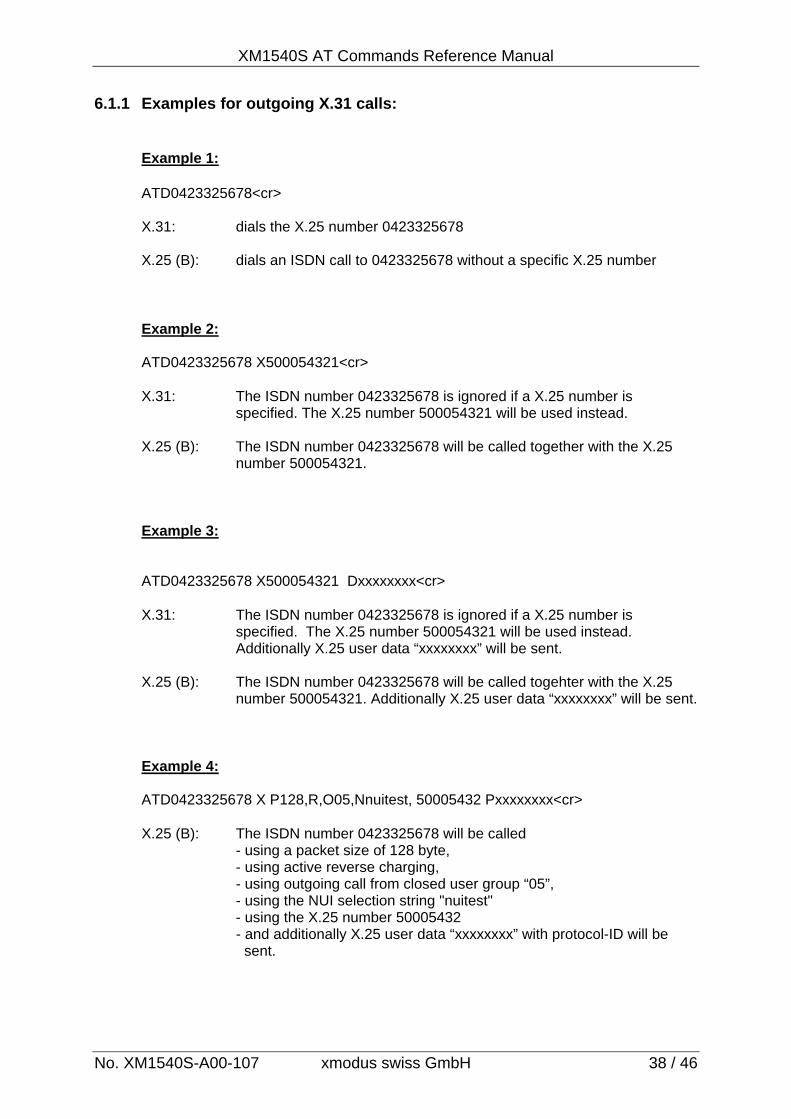
6.1.1 Examples for outgoing X.31 calls: Example 1: ATD0423325678<cr> X.31: dials the X.25 number 0423325678
X.25 (B): dials an ISDN call to 0423325678 without a specific X.25 number Example 2: ATD0423325678 X500054321<cr> X.31: The ISDN number 0423325678 is ignored if a X.25 number is specified. The X.25 number 500054321 will be used instead. X.25 (B): The ISDN number 0423325678 will be called together with the X.25 number 500054321. Example 3: ATD0423325678 X500054321 Dxxxxxxxx<cr> X.31: The ISDN number 0423325678 is ignored if a X.25 number is specified. The X.25 number 500054321 will be used instead. Additionally X.25 user data “xxxxxxxx” will be sent. X.25 (B): The ISDN number 0423325678 will be called togehter with the X.25 number 500054321. Additionally X.25 user data “xxxxxxxx” will be sent. Example 4: ATD0423325678 X P128,R,O05,Nnuitest, 50005432 Pxxxxxxxx<cr> X.25 (B): The ISDN number 0423325678 will be called - using a packet size of 128 byte, - using active reverse charging, - using outgoing call from closed user group “05”, - using the NUI selection string "nuitest" - using the X.25 number 50005432
- and additionally X.25 user data “xxxxxxxx” with protocol-ID will be sent.
XM1540S AT Command Reference Manual
No. XM1540S-A00-107 xmodus swiss GmbH 39 / 46
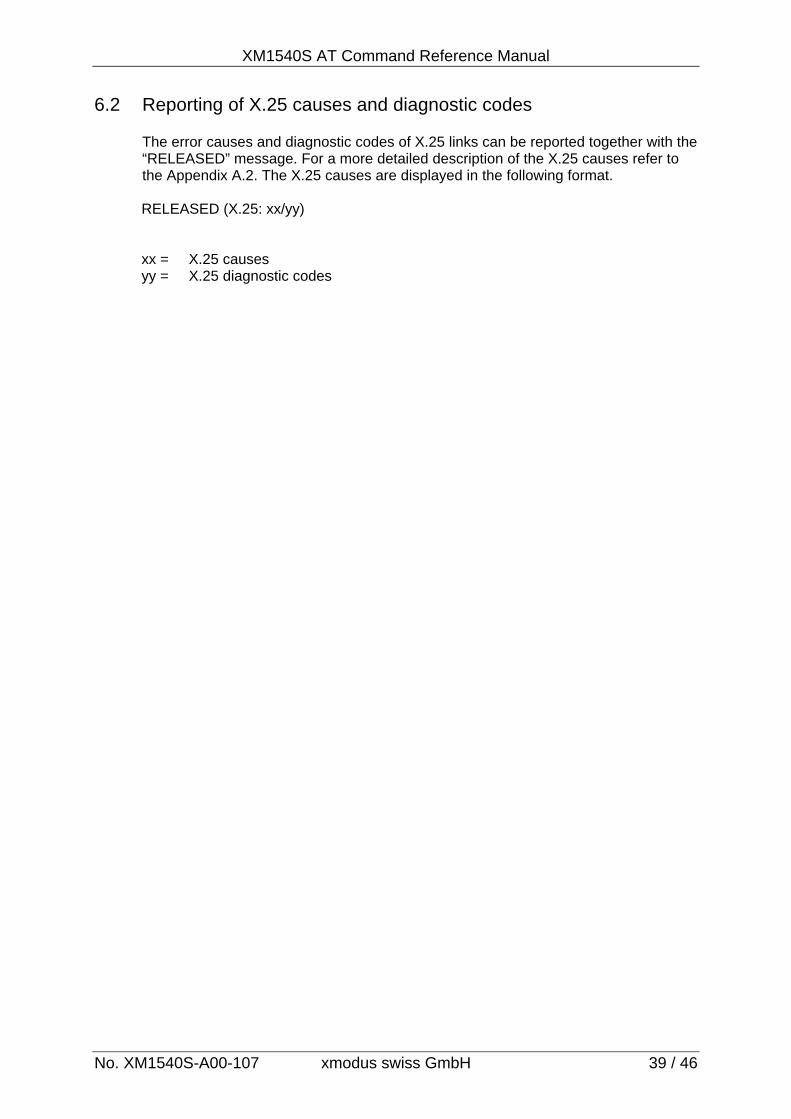
6.2 Reporting of X.25 causes and diagnostic codes
The error causes and diagnostic codes of X.25 links can be reported together with the “RELEASED” message. For a more detailed description of the X.25 causes refer to the Appendix A.2. The X.25 causes are displayed in the following format.
RELEASED (X.25: xx/yy) xx = X.25 causes yy = X.25 diagnostic codes
XM1540S AT Commands Reference Manual
No. XM1540S-A00-107 xmodus swiss GmbH 40 / 46
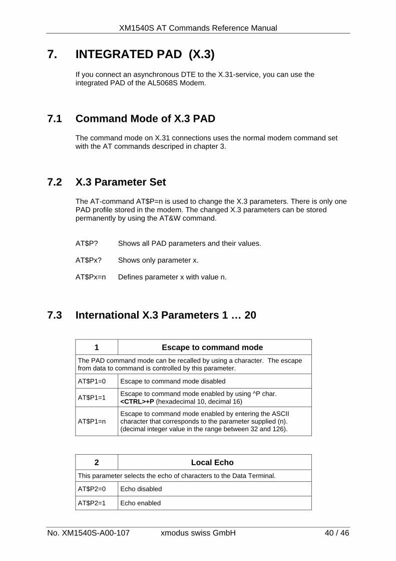
7. INTEGRATED PAD (X.3)
If you connect an asynchronous DTE to the X.31-service, you can use the integrated PAD of the AL5068S Modem.
7.1 Command Mode of X.3 PAD
The command mode on X.31 connections uses the normal modem command set with the AT commands descriped in chapter 3.
7.2 X.3 Parameter Set
The AT-command AT$P=n is used to change the X.3 parameters. There is only one PAD profile stored in the modem. The changed X.3 parameters can be stored permanently by using the AT&W command. AT$P? Shows all PAD parameters and their values. AT$Px? Shows only parameter x. AT$Px=n Defines parameter x with value n.
7.3 International X.3 Parameters 1 … 20
1 Escape to command mode
The PAD command mode can be recalled by using a character. The escape from data to command is controlled by this parameter.
AT$P1=0 Escape to command mode disabled
AT$P1=1 Escape to command mode enabled by using ^P char. <CTRL>+P (hexadecimal 10, decimal 16)
AT$P1=n Escape to command mode enabled by entering the ASCII character that corresponds to the parameter supplied (n). (decimal integer value in the range between 32 and 126).
2 Local Echo
This parameter selects the echo of characters to the Data Terminal.
AT$P2=0 Echo disabled
AT$P2=1 Echo enabled
XM1540S AT Command Reference Manual
No. XM1540S-A00-107 xmodus swiss GmbH 41 / 46
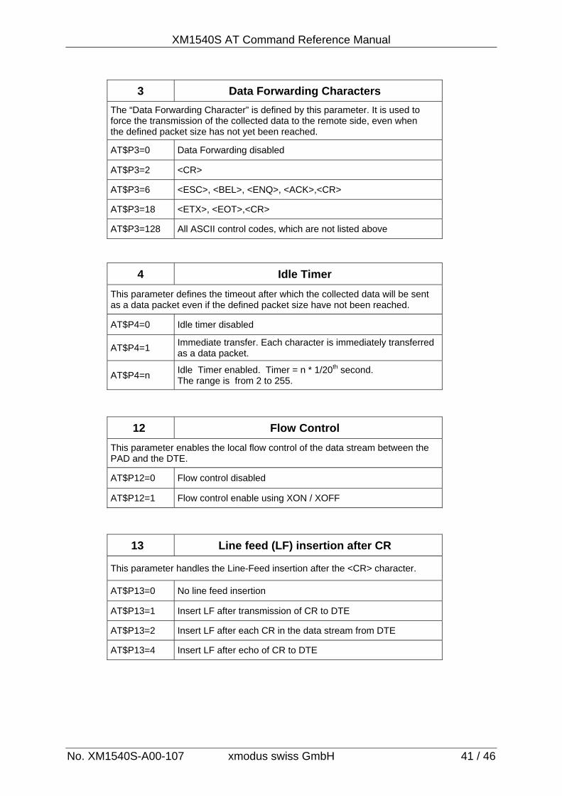
3 Data Forwarding Characters
The “Data Forwarding Character” is defined by this parameter. It is used to force the transmission of the collected data to the remote side, even when the defined packet size has not yet been reached.
AT$P3=0 Data Forwarding disabled
AT$P3=2 <CR>
AT$P3=6 <ESC>, <BEL>, <ENQ>, <ACK>,<CR>
AT$P3=18 <ETX>, <EOT>,<CR>
AT$P3=128 All ASCII control codes, which are not listed above
4 Idle Timer
This parameter defines the timeout after which the collected data will be sent as a data packet even if the defined packet size have not been reached.
AT$P4=0 Idle timer disabled
AT$P4=1 Immediate transfer. Each character is immediately transferred as a data packet.
AT$P4=n Idle Timer enabled. Timer = n * 1/20th second. The range is from 2 to 255.
12 Flow Control
This parameter enables the local flow control of the data stream between the PAD and the DTE.
AT$P12=0 Flow control disabled
AT$P12=1 Flow control enable using XON / XOFF
13 Line feed (LF) insertion after CR
This parameter handles the Line-Feed insertion after the <CR> character.
AT$P13=0 No line feed insertion
AT$P13=1 Insert LF after transmission of CR to DTE
AT$P13=2 Insert LF after each CR in the data stream from DTE
AT$P13=4 Insert LF after echo of CR to DTE
XM1540S AT Commands Reference Manual
No. XM1540S-A00-107 xmodus swiss GmbH 42 / 46
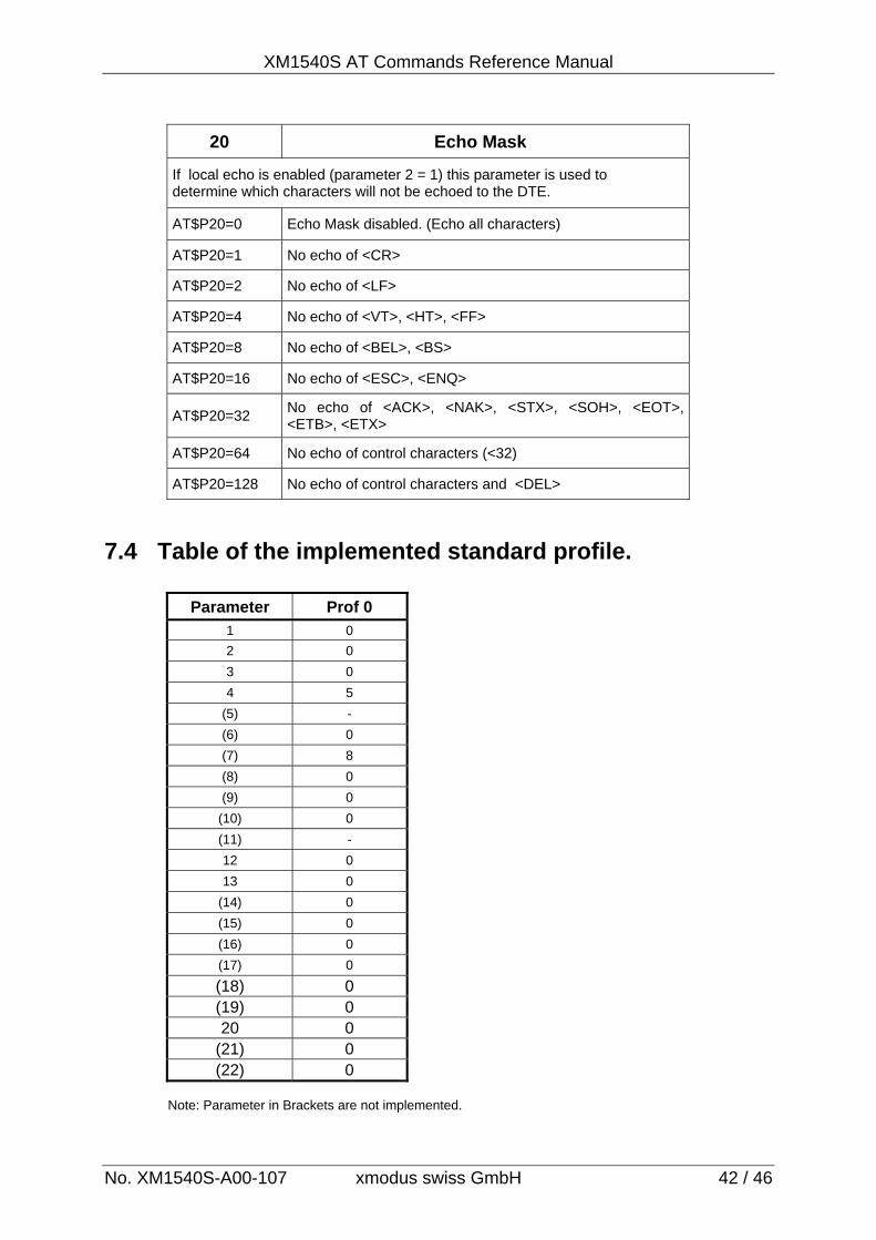
20 Echo Mask
If local echo is enabled (parameter 2 = 1) this parameter is used to determine which characters will not be echoed to the DTE.
AT$P20=0 Echo Mask disabled. (Echo all characters)
AT$P20=1 No echo of <CR>
AT$P20=2 No echo of <LF>
AT$P20=4 No echo of <VT>, <HT>, <FF>
AT$P20=8 No echo of <BEL>, <BS>
AT$P20=16 No echo of <ESC>, <ENQ>
AT$P20=32 No echo of <ACK>, <NAK>, <STX>, <SOH>, <EOT>, <ETB>, <ETX>
AT$P20=64 No echo of control characters (<32)
AT$P20=128 No echo of control characters and <DEL>
7.4 Table of the implemented standard profile.
Parameter Prof 0 1 0
2 0
3 0
4 5
(5) -
(6) 0
(7) 8
(8) 0
(9) 0
(10) 0
(11) -
12 0
13 0
(14) 0
(15) 0
(16) 0
(17) 0
(18) 0 (19) 0 20 0
(21) 0 (22) 0
Note: Parameter in Brackets are not implemented.
XM1540S AT Command Reference Manual
No. XM1540S-A00-107 xmodus swiss GmbH 43 / 46
8. FIRMWARE UPDATE
The linear flash memory uploader allows flash memory to be upgraded with revised modem firmware. This process transfers (uploads) the upgraded modem firmware (data) from the host computer to the ISDN-modem which transfers the data to the flash memory device. When the AT**FLASH command is issued, the modem firmware boot loader is invoked and the user will then load the new modem firmware which the flash memory uploader will then program into the flash memory device. This transfer is done via the 1K X-Modem protocol.
1. Put the new modem firmware file (i.e. AL5068S V1.13.txt) in an appropriate directory on the computer’s hard disk.
2. Configure the communications application program (HyperTerminal) for a DTE
rate of 115200, 8N1 and RTS/CTS flow control. An upload at 115200 bps will take approximately 1 minute. Select 1K X-Modem as the file transfer protocol.
3. Disconnect the ISDN S0 Cable from the modem.
4. Check the modem for response by typing AT.
5. Initiate the download process using the AT**FLASH command. The following
messages appears upon issuing the AT**FLASH command. Start your 1k-XMODEM transfer now (Ctrl-X aborts)..
6. Perform an 1k-XMODEM transfer of the firmware file (i.e. AL5068S V1.13.txt) from the host computer to the modem RAM using an industry standard communications software (ensure that all ASCII translation or pacing is turned off).
7. After the firmware file has been loaded successfully it will start automatically after
a software reset and the following message appears:
OK 8. Check the new firmware version with ATI3. 9. Due to firmware changes and new functionalities the stored configuration in the
Eeprom may be lost. Therefore check the configuration before use.
Upload Problems:
Due to any errors it can be possible that no firmware is active after the upload procedure. To restore the firmware correctly you have to re-enter the command AT**FLASH and load the firmware as described above. The protected boot-loader supports only the AT**FLASH command with a fixed baudrate of 115.200 Baud.
XM1540S AT Commands Reference Manual
No. XM1540S-A00-107 xmodus swiss GmbH 44 / 46
9. AUDIO MODES
The AL5068SI ISDN Modem supports 2 independent analog channels by adding 2 external PCM Codecs. The Codecs are connected to the IOM-2 bus on pins 44…47 of the socket modem. It is possible to setup 2 simultaneous links for both incoming and outgoing calls. The serial port remains in command state in this mode. The 2 external Codecs are marked with Codec A and Codec B. Each Codec (A or B) can have his own MSN. Each call can therefore be directed to a specific Codec. There are 2 additional I/O signals to drive the B-Channel source of each Codec. Please refer to the “Designers Guide” for a detailed description and schematics about the connection of the analog PCM codecs. The set-up of the calls must be sequential. After starting the first call, this call must be finished before starting a second call.
9.1 AT Command Specifications: 9.1.1 ATBn Command (selects B-Channel mode)
ATB40 : B channel transparently switched to IOM-2 (speech connection) ATB41 : B channel transparently switched to IOM-2 (data connection) ATB42 : B channel transparently switched to IOM-2 (3.1kHz Audio) ATB50 : B channel transparently switched to IOM-2 2-channel mode (speech) ATB51 : B channel transparently switched to IOM-2 2-channel mode (data) ATB52 : B channel transparently switched to IOM-2 2-channel mode (3.1kHz A.)
9.1.2 Initiate outgoing calls:
ATD command is enhanced with channel number A or B (corresponding Codec A / B) ATDAxxxxxxxxxx dials the number and makes connection for Codec A.
ATDBxxxxxxxxxx dials the number and makes connection for Codec B.
ATBn and ATDxx commands can be merged together: ATB52DA123456789<cr>
9.1.3 Answering incoming calls (manually)
ATA1A Answer call no 1 and direct to Codec A ATA1B Answer call no 1 and direct to Codec B ATA2A Answer call no 2 and direct to Codec A ATA2B Answer call no 2 and direct to Codec B
XM1540S AT Command Reference Manual
No. XM1540S-A00-107 xmodus swiss GmbH 45 / 46
9.1.4 Answering incoming calls (automatic answering)
The command AT$Zn is used to store specific MSN’s for Codec A and B. With this MSN both the Codecs can be called directly. AT&V displays the stored settings. If an MSN is stored, the incoming call will be automatic answered after issuing the “RING” message. AT$Z1=xxxxxxx stores the MSN for Codec A AT$Z2=xxxxxxx stores the MSN for Codec B AT$Z= must be empty in this mode!
9.1.5 Disconnect
ATH Disconnects all links. ATH1 Disconnect link Nr. 1 ATH2 Disconnect link Nr. 2
9.1.6 Messages
There are no additional messages. The only difference is, that the messages are preceded with a call number. This way you know, to which call the message corresponds. This also takes place in automatic answer mode (MSN stored). Additionally the called-party number is displayed together with the “RING” message in 2-channel modes (ATB50…52).
Format:
[x] RING YYYYYYY ZZZZZZZ X = Call number Y = Calling Party number
Z = Called Party number i.e.
[1] RING 4556688 7108890 ATA1A<CR> [1] CONNECTED (IOM-B1)
or:
ATB52DB4664433
[2] ALERTING
[2] CONNECTED (IOM-B2)
9.1.7 S-Register S0
In 2-channel mode S-Register S0 have no function.
XM1540S AT Commands Reference Manual
No. AL5068S-A00-106 xmodus swiss GmbH 46 / 46
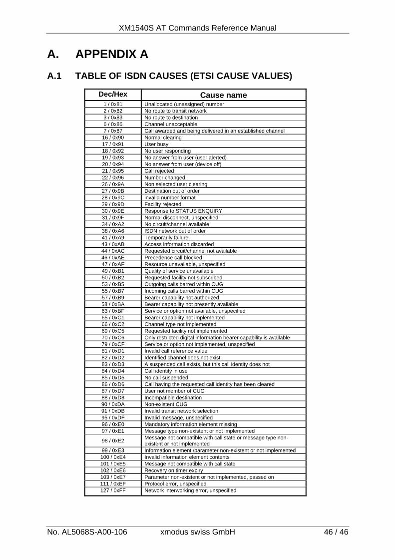
A. APPENDIX A A.1 TABLE OF ISDN CAUSES (ETSI CAUSE VALUES)
Dec/Hex Cause name 1 / 0x81 Unallocated (unassigned) number 2 / 0x82 No route to transit network 3 / 0x83 No route to destination 6 / 0x86 Channel unacceptable 7 / 0x87 Call awarded and being delivered in an established channel
16 / 0x90 Normal clearing 17 / 0x91 User busy 18 / 0x92 No user responding 19 / 0x93 No answer from user (user alerted) 20 / 0x94 No answer from user (device off) 21 / 0x95 Call rejected 22 / 0x96 Number changed 26 / 0x9A Non selected user clearing 27 / 0x9B Destination out of order 28 / 0x9C invalid number format 29 / 0x9D Facility rejected 30 / 0x9E Response to STATUS ENQUIRY 31 / 0x9F Normal disconnect, unspecified 34 / 0xA2 No circuit/channel available 38 / 0xA6 ISDN network out of order 41 / 0xA9 Temporarily failure 43 / 0xAB Access information discarded 44 / 0xAC Requested circuit/channel not available 46 / 0xAE Precedence call blocked 47 / 0xAF Resource unavailable, unspecified 49 / 0xB1 Quality of service unavailable 50 / 0xB2 Requested facility not subscribed 53 / 0xB5 Outgoing calls barred within CUG 55 / 0xB7 Incoming calls barred within CUG 57 / 0xB9 Bearer capability not authorized 58 / 0xBA Bearer capability not presently available 63 / 0xBF Service or option not available, unspecified 65 / 0xC1 Bearer capability not implemented 66 / 0xC2 Channel type not implemented 69 / 0xC5 Requested facility not implemented 70 / 0xC6 Only restricted digital information bearer capability is available 79 / 0xCF Service or option not implemented, unspecified 81 / 0xD1 Invalid call reference value 82 / 0xD2 Identified channel does not exist 83 / 0xD3 A suspended call exists, but this call identity does not 84 / 0xD4 Call identity in use 85 / 0xD5 No call suspended 86 / 0xD6 Call having the requested call identity has been cleared 87 / 0xD7 User not member of CUG 88 / 0xD8 Incompatible destination 90 / 0xDA Non-existent CUG 91 / 0xDB Invalid transit network selection 95 / 0xDF Invalid message, unspecified 96 / 0xE0 Mandatory information element missing 97 / 0xE1 Message type non-existent or not implemented
98 / 0xE2 Message not compatible with call state or message type non-existent or not implemented
99 / 0xE3 Information element /parameter non-existent or not implemented 100 / 0xE4 Invalid information element contents 101 / 0xE5 Message not compatible with call state 102 / 0xE6 Recovery on timer expiry 103 / 0xE7 Parameter non-existent or not implemented, passed on 111 / 0xEF Protocol error, unspecified 127 / 0xFF Network interworking error, unspecified
![Cis TelePresenCo Ce isDn link...ISDN PRI Interface 1 testShutdown ISDN BRI Interface [1..4] testLoopmode ISDN BRI Interface [1..4] testPattern Cisco telePresence ISDN Link Administrator](https://img.pdfslide.us/doc/110x75/6131c5191ecc51586944f1c2/cis-telepresenco-ce-isdn-link-isdn-pri-interface-1-testshutdown-isdn-bri-interface.jpg)


![ADSL Modem Router With 4-port Switch1].pdf · u ADSL over POTS (Annex A) and ADSL over ISDN (Annex B) n DMT modulation and demodulation n Full-rate adaptive modem u Maximum downstream](https://img.pdfslide.us/doc/110x75/5f024f017e708231d403a077/adsl-modem-router-with-4-port-1pdf-u-adsl-over-pots-annex-a-and-adsl-over.jpg)