Embed Size (px)
Citation preview
7/27/2019 ISA RP75.21 (1996) Process Data Presentation for Control Valves
http://slidepdf.com/reader/full/isa-rp7521-1996-process-data-presentation-for-control-valves 1/18
Recommended Practice
ISA-RP75.21-1989 (R1996)Approved February 26, 1996
Process Data Presentation
for Control Valves
7/27/2019 ISA RP75.21 (1996) Process Data Presentation for Control Valves
http://slidepdf.com/reader/full/isa-rp7521-1996-process-data-presentation-for-control-valves 2/18
Copyright © 1996 by the Instrument Society of America. All rights reserved. Printed in the UnitedStates of America. No part of this publication may be reproduced, stored in a retrieval system, ortransmitted in any form or by any means (electronic, mechanical, photocopying, recording, orotherwise), without the prior written permission of the publisher.
ISA67 Alexander DriveP.O. Box 12277Research Triangle Park, North Carolina 27709
ISA-RP75.21 — Process Data Presentation for Control Valves
ISBN 1-55617-206-0
7/27/2019 ISA RP75.21 (1996) Process Data Presentation for Control Valves
http://slidepdf.com/reader/full/isa-rp7521-1996-process-data-presentation-for-control-valves 3/18
ISA-RP75.21-1989 (R1996) 3
Preface
This preface, as well as all footnotes and annexes, is included for informational purposes and isnot part of ISA-RP75.21.
This recommended practice has been prepared as part of the service of ISA, the internationalsociety for measurement and control, toward a goal of uniformity in the field of instrumentation.To be of real value, this document should not be static, but should be subject to periodic review.Toward this end, the Society welcomes all comments and criticisms and asks that they beaddressed to the Secretary, Standards and Practices Board; ISA; 67 Alexander Drive; P. O. Box12277; Research Triangle Park, NC 27709; Telephone: (919) 549-8411; Fax: (919) 549-8288;E-mail: [email protected].
The ISA Standards and Practices Department is aware of the growing need for attention to themetric system of units in general, and the International System of Units (SI) in particular, in thepreparation of instrumentation standards, recommended practices, and technical reports. TheDepartment is further aware of the benefits to U.S.A. users of ISA standards of incorporating
suitable references to the SI (and the metric system) in their business and professional dealingswith other countries. Toward this end, this Department will endeavor to introduce SI-acceptablemetric units in all new and revised standards to the greatest extent possible. The Metric Practice Guide , which has been published by the Institute of Electrical and Electronics Engineers asANSI/IEEE Std. 268-1992, and future revisions will be the reference guide for definitions,symbols, abbreviations, and conversion factors.
It is the policy of ISA to encourage and welcome the participation of all concerned individuals andinterests in the development of ISA standards, recommended practices, and technical reports.Participation in the ISA standards-making process by an individual in no way constitutesendorsement by the employer of that individual, of ISA, or of any of the standards, recommendedpractices, and technical reports that ISA develops.
The following people served as members of ISA Subcommittee SP75.15:
NAME COMPANY
G. Barb, Chairman Consultant
W. Weidman, Managing Director Consultant
G. Borden, Jr. Consultant
G. Kovecses Keystone Yarway
C. Mates Mates Associates, Inc.
D. Rapley Rapley Engineering Services
The following people served as members of ISA Committee SP75:
NAME COMPANY
D. Buchanan, Chairman Union Carbide Corporation
W. Weidman, Managing Director Consultant
*T. Abromaitis Red Valve Company, Inc.
J. Arant JBA Consulting Company
H. Backinger J. F. Kraus & Company
*One vote per company
7/27/2019 ISA RP75.21 (1996) Process Data Presentation for Control Valves
http://slidepdf.com/reader/full/isa-rp7521-1996-process-data-presentation-for-control-valves 4/18
4 ISA-RP75.21-1989 (R1996)
NAME COMPANY
G. Baenteli Bechtel
G. Barb Consultant
H. Baumann H. D. Baumann & Associates, Ltd.
K. Black Cashco, Inc.
H. Boger Masoneilan/Dresser
G. Borden, Jr. ConsultantS. Boyle Neles-Jamesbury, Inc.
R. Brodin Fisher Controls International, Inc.
F. Cain Valtek, Inc.
C. Corson Fluor Daniel, Inc.
*C. Crawford Union Carbide Corporation
L. Driskell Consultant
*J. Duhamel Red Valve Company, Inc.
H. Fuller Consultant
*J. George Richards Industries, Inc.
L. Griffith Consultant
B. Hart M. W. Kellogg CompanyF. Harthun Consultant
B. Hatton Honeywell, Inc.
*J. Herold DeZurick Valve Company
R. Jeanes TU Electric
C. Koloboff Chevron Research & Technology Company
G. Kovecses Yarway Corporation
C. Langford Consultant
J. Leist Dow Chemical USA
*A. Libke DeZurik Valve Company
R. Louviere Creole Engineering Sales Company
O. Lovett, Jr. Retired/ConsultantA. McCauley, Jr. Chagrin Valley Controls, Inc.
H. Miller Control Components, Inc.
T. Molloy CMES
L. Ormanoski Frick Company
J. Ozol Commonwealth Edison
W. Rahmeyer Utah State University
J. Reed Norriseal Controls
*G. Richards Richards Industries, Inc.
T. Rutter Fluid Controls Institute, Inc.
K. Schoonover Con-Tek
A. Shea Copes-Vulcan, Inc.E. Skovgaard Leslie Controls
H. Sonderegger Grinnell Corporation
R. Terhune Cranmoor
R. Tubbs Industrial Valve & Gauge Company
L. Zinck Consultant
*One vote per company
7/27/2019 ISA RP75.21 (1996) Process Data Presentation for Control Valves
http://slidepdf.com/reader/full/isa-rp7521-1996-process-data-presentation-for-control-valves 5/18
ISA-RP75.21-1989 (R1996) 5
This recommended practice was approved for publication by the ISA Standards and PracticesBoard on February 26, 1996.
NAME COMPANY
M. Widmeyer, Vice President Washington Public Power Supply System
H. Baumann H. D. Baumann, Inc.
D. Bishop Chevron USA Production CompanyP. Brett Honeywell, Inc.
W. Calder, III Calder Enterprises
H. Dammeyer Phoenix Industries Inc.
R. Dieck Pratt & Whitney
W. Holland Southern Company Services, Inc.
A. Iverson Lyondell Petrochemical Company
K. Lindner Endress + Hauser GmbH + Company
T. McAvinew Metro Wastewater Reclamation District
A. McCauley, Jr. Chagrin Valley Controls, Inc.
G. McFarland Honewell Industrial Automation & Control
E. Montgomery Fluor Daniel, Inc.D. Rapley Rapley Engineering Services
R. Reimer Rockwell Automation A-B
J. Rennie Factory Mutual Research Corporation
R. Webb Pacific Gas & Electric Company
W. Weidman Consultant
J. Weiss Electric Power Research Institute
J. Whetstone National Institute of Standards & Technology
H. Wiegle Canus Corporation
C. Williams Eastman Kodak Company
G. Wood Graeme Wood Consulting
M. Zielinski Fisher•Rosemount

7/27/2019 ISA RP75.21 (1996) Process Data Presentation for Control Valves
http://slidepdf.com/reader/full/isa-rp7521-1996-process-data-presentation-for-control-valves 6/18
7/27/2019 ISA RP75.21 (1996) Process Data Presentation for Control Valves
http://slidepdf.com/reader/full/isa-rp7521-1996-process-data-presentation-for-control-valves 7/18
ISA-RP75.21-1989 (R1996) 7
Contents
1 Scope ................................................................................................................................ 9
2 Purpose ............................................................................................................................. 9
3 Definitions ......................................................................................................................... 9
4 Discussion ........................................................................................................................ 9
5 Process data envelope .................................................................................................. 10
6 Process schematic ......................................................................................................... 11
7 Process piping configuration ....................................................................................... 12
8 Process data worksheet ................................................................................................ 12
9 Suggested applications ................................................................................................. 12
Annex A — References ...................................................................................................... 15
Figures
1 — Example of a process data envelope ............................................................................ 102 — Example of a process schematic................................................................................... 113 — Examples of process piping configuration sketches...................................................... 134 — Process data worksheet ................................................................................................ 14

7/27/2019 ISA RP75.21 (1996) Process Data Presentation for Control Valves
http://slidepdf.com/reader/full/isa-rp7521-1996-process-data-presentation-for-control-valves 8/18
7/27/2019 ISA RP75.21 (1996) Process Data Presentation for Control Valves
http://slidepdf.com/reader/full/isa-rp7521-1996-process-data-presentation-for-control-valves 9/18
ISA-RP75.21-1989 (R1996) 9
1 Scope
The document describes a technique for the communication of process data and other specialrequirements among the parties involved to facilitate the selection of control valves, their
actuators, and accessories. The technique includes, but is not limited to, such features as aprocess data envelope, a process schematic, a process piping configuration, and a process dataworksheet, which may be used in combination or in part as appropriate to the specificapplication. Development and verification of design and actual process conditions at the finalcontrol element are more easily and thoroughly accomplished using a "standard format."
2 Purpose
The purpose of this document is to assure an adequate exchange of process conditions and
other pertinent information between the process system designer or the person who specifies thecontrol valve, and the control valve supplier. The technique is not intended for use on all normalapplications, but it may be a useful tool for obtaining the process data needed. Severalsuggested extraordinary applications where very complete data is required are listed inSection 9.
3 Definitions
No new definitions are required for this document. Terminology used is consistent with
ISA-S75.05, Control Valve Terminology .
4 Discussion
4.1 The success of any endeavor can be related to complete and unambiguous communicationof information among the parties involved. The successful application of a final control element toa specific process is a function of such data interchange.
4.2 Process data reduction, that is, calculation of flow coefficient (CV), flow characteristic, and
control valve selection, etc., are beyond the scope of this document.
4.3 Process data presentation may be accomplished using four distinct, yet related, formats.These formats may be used individually or combined as appropriate.
a) Process data envelope
b) Process schematic
c) Process piping configuration
d) Process data worksheet
7/27/2019 ISA RP75.21 (1996) Process Data Presentation for Control Valves
http://slidepdf.com/reader/full/isa-rp7521-1996-process-data-presentation-for-control-valves 10/18
10 ISA-RP75.21-1989 (R1996)
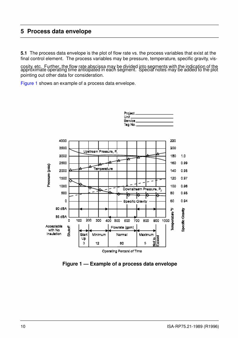
5 Process data envelope
5.1 The process data envelope is the plot of flow rate vs. the process variables that exist at thefinal control element. The process variables may be pressure, temperature, specific gravity, vis-
cosity, etc. Further, the flow rate abscissa may be divided into segments with the indication of theapproximate operating time anticipated in each segment. Special notes may be added to the plotpointing out other data for consideration.
Figure 1 shows an example of a process data envelope.
Figure 1 — Example of a process data envelope
7/27/2019 ISA RP75.21 (1996) Process Data Presentation for Control Valves
http://slidepdf.com/reader/full/isa-rp7521-1996-process-data-presentation-for-control-valves 11/18
ISA-RP75.21-1989 (R1996) 11
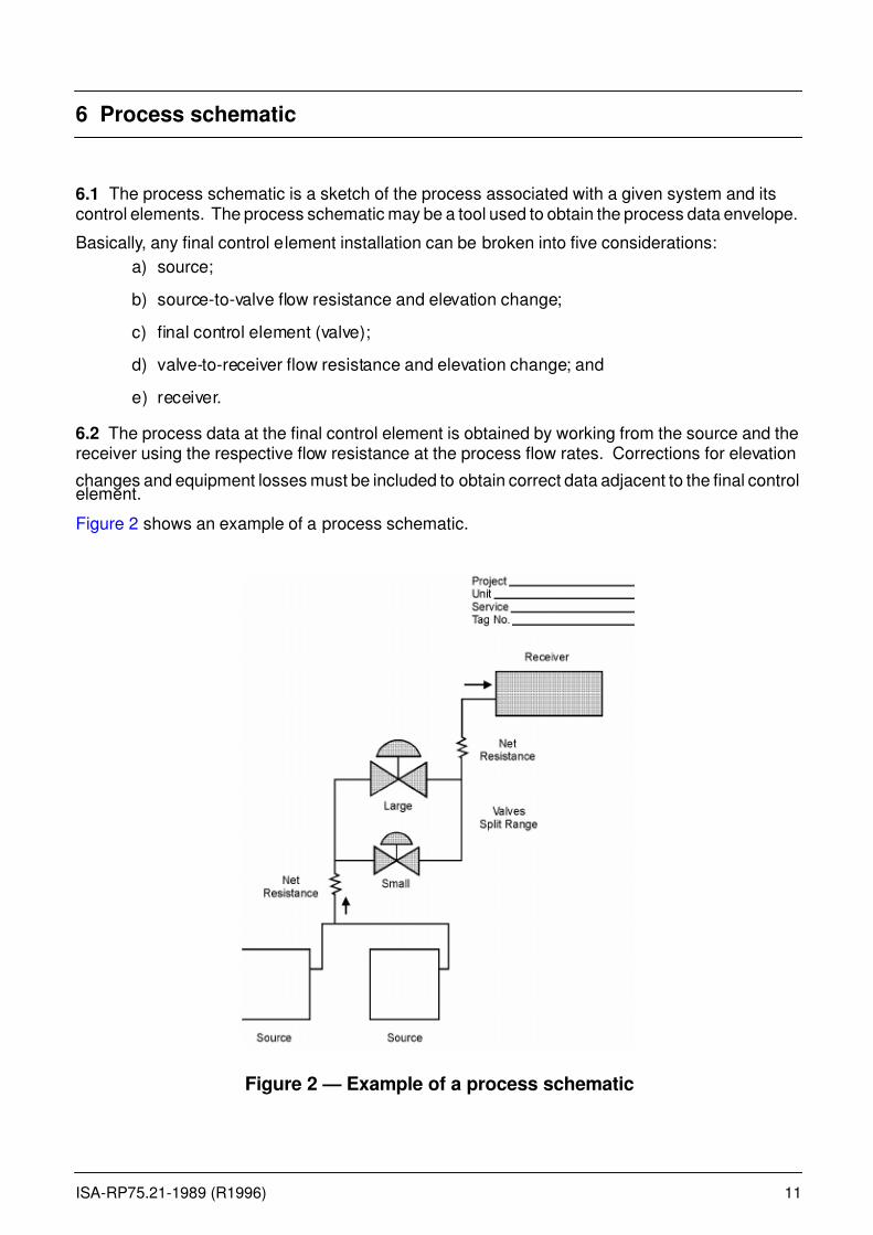
6 Process schematic
6.1 The process schematic is a sketch of the process associated with a given system and itscontrol elements. The process schematic may be a tool used to obtain the process data envelope.
Basically, any final control element installation can be broken into five considerations:
a) source;
b) source-to-valve flow resistance and elevation change;
c) final control element (valve);
d) valve-to-receiver flow resistance and elevation change; and
e) receiver.
6.2 The process data at the final control element is obtained by working from the source and thereceiver using the respective flow resistance at the process flow rates. Corrections for elevation
changes and equipment losses must be included to obtain correct data adjacent to the final controlelement.
Figure 2 shows an example of a process schematic.
Figure 2 — Example of a process schematic
7/27/2019 ISA RP75.21 (1996) Process Data Presentation for Control Valves
http://slidepdf.com/reader/full/isa-rp7521-1996-process-data-presentation-for-control-valves 12/18
12 ISA-RP75.21-1989 (R1996)
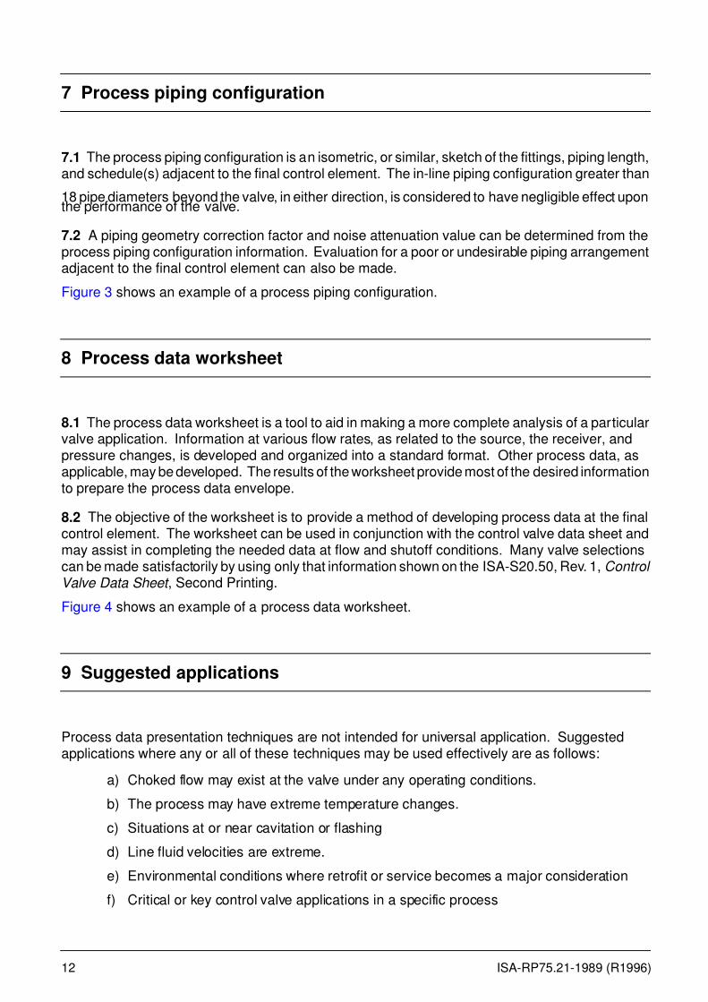
7 Process piping configuration
7.1 The process piping configuration is an isometric, or similar, sketch of the fittings, piping length,and schedule(s) adjacent to the final control element. The in-line piping configuration greater than
18 pipe diameters beyond the valve, in either direction, is considered to have negligible effect uponthe performance of the valve.
7.2 A piping geometry correction factor and noise attenuation value can be determined from theprocess piping configuration information. Evaluation for a poor or undesirable piping arrangementadjacent to the final control element can also be made.
Figure 3 shows an example of a process piping configuration.
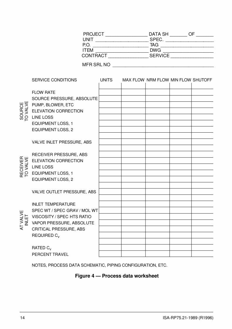
8 Process data worksheet
8.1 The process data worksheet is a tool to aid in making a more complete analysis of a particularvalve application. Information at various flow rates, as related to the source, the receiver, andpressure changes, is developed and organized into a standard format. Other process data, asapplicable, may be developed. The results of the worksheet provide most of the desired informationto prepare the process data envelope.
8.2 The objective of the worksheet is to provide a method of developing process data at the finalcontrol element. The worksheet can be used in conjunction with the control valve data sheet andmay assist in completing the needed data at flow and shutoff conditions. Many valve selectionscan be made satisfactorily by using only that information shown on the ISA-S20.50, Rev. 1, Control Valve Data Sheet , Second Printing.
Figure 4 shows an example of a process data worksheet.
9 Suggested applications
Process data presentation techniques are not intended for universal application. Suggestedapplications where any or all of these techniques may be used effectively are as follows:
a) Choked flow may exist at the valve under any operating conditions.
b) The process may have extreme temperature changes.
c) Situations at or near cavitation or flashing
d) Line fluid velocities are extreme.
e) Environmental conditions where retrofit or service becomes a major consideration
f) Critical or key control valve applications in a specific process
7/27/2019 ISA RP75.21 (1996) Process Data Presentation for Control Valves
http://slidepdf.com/reader/full/isa-rp7521-1996-process-data-presentation-for-control-valves 13/18
ISA-RP75.21-1989 (R1996) 13
g) There is potential for excessive noise generation.
h) The process fluid is of high viscosity.
i) Liquids saturated with dissolved gases/two-phase flow
j) Erosion or thinning of the downstream piping, such as an elbow near the valve outlet
k) Pressure drop is extremely small.
Figure 3 — Examples of process piping configuration sketches
6 "
7/27/2019 ISA RP75.21 (1996) Process Data Presentation for Control Valves
http://slidepdf.com/reader/full/isa-rp7521-1996-process-data-presentation-for-control-valves 14/18
14 ISA-RP75.21-1989 (R1996)
PROJECT _________________ DATA SH _______ OF _______ UNIT _____________________ SPEC. ___________________ P.O. ______________________ TAG _____________________ ITEM _____________________ DWG ____________________ CONTRACT ________________ SERVICE _________________
MFR SRL NO ________________________________________
Figure 4 — Process data worksheet
SERVICE CONDITIONS UNITS MAX FLOW NRM FLOW MIN FLOW SHUTOFF
FLOW RATE
SOURCE PRESSURE, ABSOLUTE
PUMP, BLOWER, ETC
ELEVATION CORRECTION
LINE LOSS
EQUIPMENT LOSS, 1
EQUIPMENT LOSS, 2
VALVE INLET PRESSURE, ABS
RECEIVER PRESSURE, ABS
ELEVATION CORRECTION
LINE LOSS
EQUIPMENT LOSS, 1
EQUIPMENT LOSS, 2
VALVE OUTLET PRESSURE, ABS
INLET TEMPERATURE
SPEC WT / SPEC GRAV / MOL WT
VISCOSITY / SPEC HTS RATIO
VAPOR PRESSURE, ABSOLUTE
CRITICAL PRESSURE, ABS
REQUIRED Cv
RATED Cv
PERCENT TRAVEL
NOTES, PROCESS DATA SCHEMATIC, PIPING CONFIGURATION, ETC.
S O U R C E
T O V
A L V E
R E C E I V E R
T O V
A L V E
A T V A L V E
I N L E T
7/27/2019 ISA RP75.21 (1996) Process Data Presentation for Control Valves
http://slidepdf.com/reader/full/isa-rp7521-1996-process-data-presentation-for-control-valves 15/18
ISA-RP75.21-1989 (R1996) 15
Annex A — References
ISA
S20.50, Rev. 1 Control Valve Data SheetSecond Printing
S51.1-1993 (R) Process Instrumentation Terminology
S75.01-1995 (R) Flow Equations for Sizing Control Valves
S75.02-1993 (R) Control Valve Capacity Test Procedures
S75.05-1983 Control Valve Terminology
ISA Handbook of Control Valves, 2nd Edition, J. W. Hutchison, Editor.
Available from: ISAP.O. Box 1227767 Alexander DriveResearch Triangle Park, NC 27709 Tel. (919) 990-9200
MISCELLANEOUS
Technical Paper No. 410, "Flow of Fluids through Valve Fittings and Pipe," (Crane Company,Chicago).
George E. Russel, Hydraulics , Fifth Edition, Henry Holt and Company, 1942.
Stephen S. Miller, "Sizing Steam Piping Using a Personal Computer," Power Engineering ,March 1986.

7/27/2019 ISA RP75.21 (1996) Process Data Presentation for Control Valves
http://slidepdf.com/reader/full/isa-rp7521-1996-process-data-presentation-for-control-valves 16/18

7/27/2019 ISA RP75.21 (1996) Process Data Presentation for Control Valves
http://slidepdf.com/reader/full/isa-rp7521-1996-process-data-presentation-for-control-valves 17/18
7/27/2019 ISA RP75.21 (1996) Process Data Presentation for Control Valves
http://slidepdf.com/reader/full/isa-rp7521-1996-process-data-presentation-for-control-valves 18/18
Developing and promulgating technically sound consensus standards,
recommended practices, and technical reports is one of ISA's primarygoals. To achieve this goal the Standards and Practices Departmentrelies on the technical expertise and efforts of volunteer committeemembers, chairmen, and reviewers.
ISA is an American National Standards Institute (ANSI) accreditedorganization. ISA administers United States Technical AdvisoryGroups (USTAGs) and provides secretariat support for InternationalElectrotechnical Commission (IEC) and International Organization forStandardization (ISO) committees that develop process measurementand control standards. To obtain additional information on theSociety's standards program, please write:
ISAAttn: Standards Department67 Alexander DriveP.O. Box 12277Research Triangle Park, NC 27709
ISBN: 1-55617-206-0