Embed Size (px)
Citation preview

IS31FL3731 16x9 Charlieplexed PWM LED DriverCreated by lady ada
Last updated on 2018-08-22 03:52:56 PM UTC

2477899
1111111213
14141415
1723232324242626262626282828
2929
293335353638383838
Guide Contents
Guide ContentsOverviewPinoutsPower PinsI2C Data PinsOther Control PinsLED GridAssemblyAssemble the IS31 Driver Board
Prepare the header strip:Add the breakout board:And Solder!
Solder Driver Headers for LEDsPrepare the header strip:Add the breakout board face up:And Solder!
Attach LED panelArduino Wiring & TestWiringDownload Adafruit_IS31FL3731 libraryInstall Adafruit GFXLoad DemoLibrary ReferenceInitializeDrawingAdafruit GFXMultiple BuffersCircuitPythonAdafruit CircuitPython Module Install
Bundle Install
UsageI2C Initialization
Charlieplex UsageFull ExampleWiringPartsWiringPython & CircuitPythonCircuitPython Microcontroller WiringPython Computer WiringCircuitPython Installation of IS31FL3731 Library
© Adafruit Industries https://learn.adafruit.com/i31fl3731-16x9-charliplexed-pwm-led-driver Page 2 of 47

3939434445454546
Python Installation of IS31FL3731 LibraryCircuitPython & Python UsageFull Example CodePython DocsDownloadsDatasheets & FilesIS31FL3731 Breakout16x9 0603 LED Grid
© Adafruit Industries https://learn.adafruit.com/i31fl3731-16x9-charliplexed-pwm-led-driver Page 3 of 47

Overview
The IS31FL3731 will let you get back to that classic LED matrix look, with a nice upgrade! This I2C LED driver chip hasthe ability to PWM each individual LED in a 16x9 grid so you can have beautiful LED lighting effects, without a lot ofpin twiddling. Simply tell the chip which LED on the grid you want lit, and what brightness and it's all taken care of foryou.
© Adafruit Industries https://learn.adafruit.com/i31fl3731-16x9-charliplexed-pwm-led-driver Page 4 of 47

The IS31FL3731 is a nice little chip - it can use 2.7-5.5V power and logic so its flexible for use with any microcontroller.You can set the address so up to 4 matrices can share an I2C bus. Inside is enough RAM for 8 separate frames ofdisplay memory so you can set up multiple frames of an animation and flip them to be displayed with a singlecommand.
© Adafruit Industries https://learn.adafruit.com/i31fl3731-16x9-charliplexed-pwm-led-driver Page 5 of 47

This chip is great for making small LED displays, and we even designed the breakout to match up with our ready-to-goLED grids in red, yellow, green, blue and white. Sandwich the driver and matrix breakout, solder together for acompact setup. Or you can DIY your own setup, just follow the LED grid schematic in the IS31FL3731 datasheet.
Pick up a driver board and your favorite color LEDs to match. You'll need to do some basic soldering to attach thedriver backpack and matrix together, and run wires to your microcontroller, but its not too hard. Then install ourArduino code to get some LEDs blinking immediately. Our library is Adafruit_GFX compatible so you can draw lines,circles, text, and small bitmaps if you want more graphics control
© Adafruit Industries https://learn.adafruit.com/i31fl3731-16x9-charliplexed-pwm-led-driver Page 6 of 47

Pinouts
The IS31FL3731 has a lot of pins, and we wanted to make it easy to use with a breadboard while sandwiched with anLED matrix. The easiest way we could figure out to do this is make the board as large as our 0603-LED 16x9 matrixgrids and have a control header on one edge. That way you can solder the two long headers directly to the matrix andstill have access to pins for power and data.
Power Pins
© Adafruit Industries https://learn.adafruit.com/i31fl3731-16x9-charliplexed-pwm-led-driver Page 7 of 47

You can power the IS31 from 2.7-5.5VDC, but note that the same voltage is used for both power and logic.
If you are using a 5V logic device, just connect VCC to 5V.
If you are using a 3.3V logic, you can either power with 3.3V, which will work fine for red, yellow or light green LEDs oryou can power from 5V and then use ~2.2K resistors from SDA and SCL to 3.3V to 'overpower' the built in 20K pullupresistors.
I2C Data Pins
© Adafruit Industries https://learn.adafruit.com/i31fl3731-16x9-charliplexed-pwm-led-driver Page 8 of 47

This chip uses I2C for control, it does not use clock stretching or repeated start. There are built in 20K pullups to VCC.You can run it as fast as 400KHz clock speed, but you may need to add additional 2K pullups from SDA and SCL up toVCC for higher speeds
SDA - I2C data line, connect to your microcontroller's I2C SDA pinSCL - I2C clock line, connect to your microcontroller's I2C SCL pin
Other Control Pins
SD - Shutdown pin, default pulled up to VCC. Connect to ground to put the chip in shutdown modeAUD - Audio input, can be used to modulate the entire display with the amplitude of a line level audio signal, hasa series capacitor installed.ADDR and jumpers - By default the address is 0x74 but you can close one of the jumpers to change the addressfor up to 4 devices with varying addressesINTB - Output interrupt from chip when using the built in animation modes
LED Grid
The LED Grid is much simpler, it just has 2 charlieplex grids, 16x9 total 0603 LEDs, with the two grids broken out toside pins that line up with the driver
© Adafruit Industries https://learn.adafruit.com/i31fl3731-16x9-charliplexed-pwm-led-driver Page 9 of 47

© Adafruit Industries https://learn.adafruit.com/i31fl3731-16x9-charliplexed-pwm-led-driver Page 10 of 47

Assembly
Assemble the IS31 Driver Board
We'll start by soldering in the 7-pin 'control' header. Break the headers you received so that you have a 7-pin pieceand collow these steps.
Prepare the header strip:Cut the strip to length if necessary. It will be easier to
solder if you insert it into a breadboard - long pins down
© Adafruit Industries https://learn.adafruit.com/i31fl3731-16x9-charliplexed-pwm-led-driver Page 11 of 47

Add the breakout board:Place the breakout board over the pins so that the short
pins poke through the breakout pads
And Solder!Be sure to solder all pins for reliable electrical contact.
(For tips on soldering, be sure to check out our Guide toExcellent Soldering (https://adafru.it/aTk)).
© Adafruit Industries https://learn.adafruit.com/i31fl3731-16x9-charliplexed-pwm-led-driver Page 12 of 47

OK the control port header is done.
Check your solder joints visually and continue onto the
next steps
Solder Driver Headers for LEDs
The two side strips are what are used to control the charlie-plexed LEDs
© Adafruit Industries https://learn.adafruit.com/i31fl3731-16x9-charliplexed-pwm-led-driver Page 13 of 47

Prepare the header strip:Cut the strip to length if necessary. It will be easier to
solder if you insert it into a breadboard - long pins down
Add the breakout board face up:Place the breakout board over the pins so that the short
pins poke through the breakout pads
And Solder!Be sure to solder all pins for reliable electrical contact.
(For tips on soldering, be sure to check out our Guide toExcellent Soldering (https://adafru.it/aTk)).
© Adafruit Industries https://learn.adafruit.com/i31fl3731-16x9-charliplexed-pwm-led-driver Page 14 of 47

© Adafruit Industries https://learn.adafruit.com/i31fl3731-16x9-charliplexed-pwm-led-driver Page 15 of 47

© Adafruit Industries https://learn.adafruit.com/i31fl3731-16x9-charliplexed-pwm-led-driver Page 16 of 47

OK now you have the control and LED pads with
headers.
Check your solder joints visually and continue onto the
next steps
Attach LED panel
Now we'll sandwich on the charlieplexed LED panel
The LEDs face out and connect to the two side header
strips.
The panel is symmetric - you can flip it around either
way and it will work fine
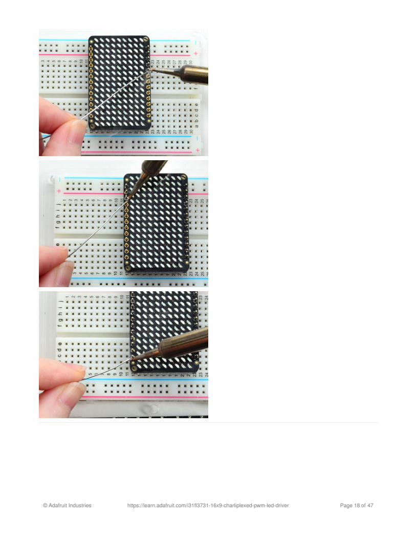
Solder in the two long header strips. Not all are
connected on the LED matrix but it makes the
connections mechanically stable.
© Adafruit Industries https://learn.adafruit.com/i31fl3731-16x9-charliplexed-pwm-led-driver Page 17 of 47
© Adafruit Industries https://learn.adafruit.com/i31fl3731-16x9-charliplexed-pwm-led-driver Page 18 of 47

Check your solder joints visually and continue onto the
next steps
© Adafruit Industries https://learn.adafruit.com/i31fl3731-16x9-charliplexed-pwm-led-driver Page 19 of 47

Now you can trim the long header with diagonal cutters.
Cut one or two pins at a time
Watch out for flying header bits. Wear eye protection
and be careful!
© Adafruit Industries https://learn.adafruit.com/i31fl3731-16x9-charliplexed-pwm-led-driver Page 20 of 47

Cut both sides down for the best look
You're done! Check your solder joints visually and
continue onto the next steps
© Adafruit Industries https://learn.adafruit.com/i31fl3731-16x9-charliplexed-pwm-led-driver Page 21 of 47

Arduino Wiring & Test
You can easily wire this breakout to any microcontroller, we'll be using an Arduino. For another kind of microcontroller,as long as you have I2C pins available, just check out the library, then port the code.
Wiring
Use this wiring if you want to connect via I2C interface
Connect Vin to the power supply, 3-5V is fine. Use the same voltage that the microcontroller logic is based off of.For most Arduinos, that is 5VConnect GND to common power/data groundConnect the SCL pin to the I2C clock SCL pin on your Arduino. On an UNO & '328 based Arduino, this is alsoknown as A5, on a Mega it is also known as digital 21 and on a Leonardo/Micro, digital 3Connect the SDA pin to the I2C data SDA pin on your Arduino. On an UNO & '328 based Arduino, this is alsoknown as A4, on a Mega it is also known as digital 20 and on a Leonardo/Micro, digital 2
Download Adafruit_IS31FL3731 library
To begin reading sensor data, you will need to download Adafruit_IS31FL3731 from our githubrepository (https://adafru.it/lWA). You can do that by visiting the github repo and manually downloading or, easier, justclick this button to download the zip
https://adafru.it/lWB
https://adafru.it/lWB
Rename the uncompressed folder Adafruit_IS31FL3731 and check that the Adafruit_IS31FL3731 folder containsAdafruit_IS31FL3731.cpp and Adafruit_IS31FL3731.h
© Adafruit Industries https://learn.adafruit.com/i31fl3731-16x9-charliplexed-pwm-led-driver Page 22 of 47

Place the Adafruit_IS31FL3731 library folder your arduinosketchfolder/libraries/ folder. You may need to create the libraries subfolder if its your first library. Restart the IDE.
We also have a great tutorial on Arduino library installation at:http://learn.adafruit.com/adafruit-all-about-arduino-libraries-install-use (https://adafru.it/aYM)
Install Adafruit GFX
You will need to do the same for the Adafruit_GFX library available here (https://adafru.it/aJa)
https://adafru.it/cBB
https://adafru.it/cBB
Rename the uncompressed folder Adafruit_GFX and check that the Adafruit_GFX folder contains Adafruit_GFX.cppand Adafruit_GFX.h
Place the Adafruit_GFX library folder your arduinosketchfolder/libraries/ folder like you did with the IS31FL library
Load Demo
Open up File->Examples->Adafruit_IS31FL3731->swirldemo and upload to your Arduino wired up to the driver & matrix
Upload to your Arduino, you'll see the LED display swirl different brightnesses!
© Adafruit Industries https://learn.adafruit.com/i31fl3731-16x9-charliplexed-pwm-led-driver Page 23 of 47

© Adafruit Industries https://learn.adafruit.com/i31fl3731-16x9-charliplexed-pwm-led-driver Page 24 of 47

Library ReferenceNow that you have the demo working, you can control the matrix directly.
Initialize
Start by creating a new matrix object with something like:
There's no arguments to the constructor
Then in your setup, call begin(address) to initialize the driver. Begin() will return false if the matrix was not found, andtrue if initialization worked out
Drawing
You can then draw to the display. Note that since we write directly to the driver RAM, any pixels 'drawn' will appearimmediately.
You can start with drawPixel(x, y, brightness) where x ranges between 0 and 15 inclusive, and y ranges between 0 and8 inclusive. Brightness is the PWM of the LED, 0 is off, and 255 is all the way on.
This loop will light up every LED in increasing brightness:
Adafruit GFX
Once you get pixels drawing, you can use Adafruit GFX to draw lines, rectangles, circles, text, etc.
The Adafruit_GFX library for Arduino provides a common syntax and set of graphics functions for all of our LED, TFT,LCD and OLED displays. This allows Arduino sketches to easily be adapted between display types with minimal fuss…and any new features, performance improvements and bug fixes will immediately apply across our complete offeringof color displays.
Check out our detailed tutorial here http://learn.adafruit.com/adafruit-gfx-graphics-library (https://adafru.it/aPx) It coversthe latest and greatest of the GFX library!
Multiple Buffers
Adafruit_IS31FL3731 ledmatrix = Adafruit_IS31FL3731();
if (! ledmatrix.begin()) { Serial.println("IS31 not found"); while (1); } Serial.println("IS31 found!");
int i = 0;for (uint8_t x=0; x<16; x++) { for (uint8_t y=0; y<9; y++) { ledmatrix.drawPixel(x, y, i++]); }}
© Adafruit Industries https://learn.adafruit.com/i31fl3731-16x9-charliplexed-pwm-led-driver Page 25 of 47

The IS31 has 8 full display frame buffers available. By default you draw and display to frame buffer #0
But! If you want to flip thru different images quickly, you can double buffer by writing to one buffer and then telling theIS31 to switch which one is visible.
To set which frame we are drawing to, use setFrame(n) where n ranges from 0 to 7 inclusive
Then when you are ready to display it, to set which frame we are displaying to, use displayFrame(n) where n ranges from 0 to 7 inclusive
ledmatrix.setFrame(frame);
ledmatrix.displayFrame(frame);
© Adafruit Industries https://learn.adafruit.com/i31fl3731-16x9-charliplexed-pwm-led-driver Page 26 of 47

CircuitPythonAdafruit CircuitPython Module Install
To use the Charlieplex display with your Adafruit CircuitPython (https://adafru.it/tCy) board you'll need to installthe Adafruit_CircuitPython_IS31FL3731 (https://adafru.it/zlE) module on your board. Remember this module is forAdafruit CircuitPython firmware and not MicroPython.org firmware!
First make sure you are running the latest version of Adafruit CircuitPython (https://adafru.it/tBa) for your board. Nextyou'll need to install the necessary libraries to use the hardware--read below and carefully follow the referenced stepsto find and install these libraries from Adafruit's CircuitPython library bundle (https://adafru.it/zdx).
Bundle Install
For express boards that have extra flash storage, like the Feather/Metro M0 express and Circuit Playground express,you can easily install the necessary libraries with Adafruit's CircuitPython bundle (https://adafru.it/zdx). This is an all-in-one package that includes the necessary libraries to use the IS31FL3731 Charlieplex driver with CircuitPython. Toinstall the bundle follow the steps in your board's guide, like these steps for the Feather M0 expressboard (https://adafru.it/zco).
Remember for non-express boards like the Trinket M0, Gemma M0, and Feather/Metro M0 basic you'll need tomanually install the necessary libraries from the bundle:
adafruit_is31fl3731.mpy
If your board supports USB mass storage, like the M0-based boards, then simply drag the files to the board's filesystem. Note on boards without external SPI flash, like a Feather M0 or Trinket/Gemma M0, you might run intoissues on Mac OSX with hidden files taking up too much space when drag and drop copying, see this page for aworkaround (https://adafru.it/u1d).
If your board doesn't support USB mass storage, like the ESP8266, then use a tool like ampy to copy the file to theboard (https://adafru.it/s1f). You can use the latest version of ampy and its new directory copycommand (https://adafru.it/q2A) to easily move module directories to the board.
Before continuing make sure your board's lib folder or root filesystem has the adafruit_is31fl3731.mpy module copiedover.
© Adafruit Industries https://learn.adafruit.com/i31fl3731-16x9-charliplexed-pwm-led-driver Page 27 of 47

Usage
The following section will show how to control the Charlieplex display from the board's Python prompt / REPL. You'lllearn how to interactively control the display, turn on/off LEDs, control brightness and more by typing in the codebelow.
First connect to the board's serial REPL (https://adafru.it/pMf)so you are at the CircuitPython >>> prompt.
I2C Initialization
First you'll need to initialize the I2C bus for your board. First import the necessary modules:
Note if you're using the ESP8266 or other boards which do not support hardware I2C you need to import from thebitbangio module instead of busio:
Now for either board run this command to create the I2C instance using the default SCL and SDA pins (which will bemarked on the boards pins if using a Feather or similar Adafruit board):
Charlieplex Usage
Once I2C is initialized you're ready to import and use the Charlieplex module. First import the adafruit_is31fl3731
import boardimport busio as io
import boardimport bitbangio as io
i2c = io.I2C(board.SCL, board.SDA)
© Adafruit Industries https://learn.adafruit.com/i31fl3731-16x9-charliplexed-pwm-led-driver Page 28 of 47

module by running:
Next depending on what display you're using you can create an instance of a Charlieplex display class:
Matrix - This class represents the 16 x 9 LED grid matrix used by the Charlieplex driver breakout.CharlieWing - This class represents the 15 x 7 LED Charlieplex FeatherWing.
For example to use the CharlieWing you can run:
Note that you need to pass the I2C bus created above into the initializer for the class.
Alternatively you can use the Charlieplex driver & matrix breakout by running:
If you've changed the I2C address of the Charlieplex driver you can specify it with an optional address keywordparameter too. For example if the driver has an I2C address of 0x77 you can run:
The address parameter can be used with the CharlieWing class too.
When the display initializes it will go through and clear each frame (there are 8 frames total) of the display. You mightsee the display momentarily flash and then turn off to a clear no pixel lit image.
You can control all of the board's pixels using the fill function. Send to this function a value from 0 to 255 where 0 isevery LED pixel turned off and 255 is every LED pixel turned on to maximum brightness. For example to set all thepixels to half their brightness run:
import adafruit_is31fl3731
display = adafruit_is31fl3731.CharlieWing(i2c)
display = adafruit_is31fl3731.Matrix(i2c)
display = adafruit_is31fl3731.Matrix(i2c, address=0x77)
display.fill(127)
© Adafruit Industries https://learn.adafruit.com/i31fl3731-16x9-charliplexed-pwm-led-driver Page 29 of 47

You might notice some buzzing or ringing sounds from the display when all pixels are lit, this is normal as theCharlieplex driver quickly switches LEDs on and off.
If you've used other displays like LED matrices you might notice the Charlieplex module doesn't need to have a showfunction called to make the changes visible. As soon as you call fill or other display functions the display will update!
You can turn all the pixels off by filling them with color 0:
Now for some fun! You can set any of the LED pixels using the pixel function. This function takes the followingparameters:
X position - The location of the horizontal / X pixel position.Y position - The location of the vertical / Y pixel position.Intensity - This is a value from 0 to 255 which specifies how bright the pixel should be, 0 is off and 255 ismaximum brightness. Use an in-between value to show a less bright pixel.
For example to set pixel 0, 0 to full brightness run:
display.fill(0)
Be careful setting all pixels to 255 maximum brightness! This might pull more power than your computer'sUSB port can provide if you are powering your board over USB. Use an external powers supply or batterywhen lighting lots of LEDs to max brightness.
display.pixel(0, 0, 255)
© Adafruit Industries https://learn.adafruit.com/i31fl3731-16x9-charliplexed-pwm-led-driver Page 30 of 47

Or to set the pixel next to it horizontally to half brightness run:
You can turn off individual pixels by setting them to an intensity of zero.
You can even make pixels blink! The board supports a fixed blink rate that you set using the blink function. Thisfunction takes in the number of milliseconds to use for the blink rate (but internally it can only blink in 270msincrements so you might not get an exact match). For example to blink pixels about once every half second call:
You'll notice nothing actually changes on the board. This is because in addition to intensity each LED pixel has a blinkstate which can be enabled and disabled. The fill command can actually set all pixels and turn them on to blink:
You can turn off the blinking by setting blink=False.
The pixel command supports the blink parameter too! You can turn on and off blinking pixel by pixel as needed. Forexample to turn on blinking for pixel 0, 0:
display.pixel(1, 0, 127)
display.blink(500)
display.fill(127, blink=True)
© Adafruit Industries https://learn.adafruit.com/i31fl3731-16x9-charliplexed-pwm-led-driver Page 31 of 47

Currently the Charlieplex module is very simple and only exposes pixel set commands. In the future more advancedgraphics commands like line drawing, text display, etc. might be implemented but for now you'll need to manipulatethe pixels yourself.
Finally the display supports holding up to 8 frames of pixel data. Each frame contains an entire matrix of LED pixelstate (intensity, blinking, etc.) and by default the module starts you on frame 0. You can change to start displaying anddrawing on another frame by calling frame which takes these parameters:
Frame number - This is the frame number to make the active frame for display or drawing. There are 8 framestotal, 0 through 7.Show - An optional boolean that defaults to True and specifies if the frame should be immediately displayed(True) or just made active so that pixel and fill commands draw on it but it's not yet shown.
For example to clear frame 1 and draw a few pixels on it, then display it you can run:
Notice how the first call switches to make frame 1 the active frame but doesn't display it because show is set to false. Then the frame pixel data is changed with fill and pixel commands, and finally the frame is shown by calling frameagain but letting the default show = True be used so the frame is displayed.
Using frames you can build simple animations by drawing each frame and swapping between them over time!
That's all there is to the basic Charlieplex driver module usage! Be sure to see the moduledocumentation (https://adafru.it/scK) for more details on advanced usage.
Full Example
Here's a complete example that randomly turns on LEDs for the Charlieplex FeatherWing. This is good to review all
display.pixel(0, 0, 127, blink=True)
display.frame(1, show=False)display.fill(0)display.pixel(0, 0, 255)display.pixel(1, 1, 255)display.pixel(2, 2, 255)display.frame(1) # show=True is the default, the frame will be displayed!
© Adafruit Industries https://learn.adafruit.com/i31fl3731-16x9-charliplexed-pwm-led-driver Page 32 of 47

the steps of setting up the display and drawing pixels. You can read the comments to learn more about the randomnumber generation functions in CircuitPython and MicroPython's random module too. Save this file as a main.py onyour board's root file system and watch it randomly turn on LEDs to different intensity values.
# Charlieplex FeatherWing random pixel drawing demo.# Author: Tony DiCola# License: Public Domain
# Import necessary libraries:import board# If using an M0 board with hardware I2C use this line:import busio as io# If using the ESP8266 with software I2C use this line instead:#import bitbangio as ioimport randomimport time
import adafruit_is31fl3731
# Initialize I2C bus:i2c = io.I2C(board.SCL, board.SDA)
# Create the FeatherWing display:display = adafruit_is31fl3731.CharlieWing(i2c)
# Turn off all the pixels.display.fill(0)
# Main loop forever turning on/off random pixels and delaying for random amounts# of time.while True: # Generate random X, Y coordinates within the FeatherWing display bounds. x = random.randrange(0, 16) # randrange generates a random number within y = random.randrange(0, 8) # the first parameter and up to but not # including the second parameter. # Generate a random intensity within the range of 0 to 192: intensity = random.randrange(0, 193) # Set the pixel. display.pixel(x, y, intensity) # Delay for a random small period of time. The uniform function # generates a floating point value (i.e. fractional) within the specified # range (inclusive for first parameter, exclusive for second). # Sleep for a short ~10 to 100 millisecond period of time. time.sleep(random.uniform(0.01, 0.1))
© Adafruit Industries https://learn.adafruit.com/i31fl3731-16x9-charliplexed-pwm-led-driver Page 33 of 47

WiringParts
You'll need the following parts to follow this guide:
CircuitPython board. This guide focuses on
the ESP8266 (https://adafru.it/n6A) and Feather
M0/SAMD21-based boards (http://adafru.it/2772), but
any CircuitPython board that supports I2C should work.
If your board doesn't come with CircuitPython running
on it already then check out your board's guide for how
to load CircuitPython firmware. For example the Feather
M0 express guide (https://adafru.it/wbv) is a good
reference.
If you're using a Feather board and FeatherWing you
probably want a Feather female header
set (http://adafru.it/2886) or Feather stacking female
header set (http://adafru.it/2830).
Charlieplex Matrix & Driver or FeatherWing. If you're
using a Feather the CharliePlex
FeatherWing (http://adafru.it/2965) is the perfect option
that easily connects to the Feather. For other boards
you'll need a Charlieplex
driver (http://adafru.it/2946) and
matrix (https://adafru.it/scH) (they are separate
components that must be connected together).
© Adafruit Industries https://learn.adafruit.com/i31fl3731-16x9-charliplexed-pwm-led-driver Page 34 of 47

Breadboard (http://adafru.it/64)and jumper
wires (http://adafru.it/153). If you aren't using a Feather
and FeatherWing you'll need a breadboard and jumper
wires to connect the components.
Soldering tools (http://adafru.it/136). You'll need to
solder headers to the boards Check out the guide to
excellent soldering (https://adafru.it/dxy) if you're new to
soldering.
Make sure to follow the board and Charlieplex FeatherWing (https://adafru.it/scD) or driver (https://adafru.it/scE)product guides to assemble and verify they work before continuing.
Wiring
If you're using a FeatherWing and Feather just slide the wing onto the Feather board and you're all set! TheFeatherWing will automatically be connected to the board using its I2C connection. Skip to the next page to learnabout the software to control the display.
If you're using a Charlieplex breakout you'll need to connect its power, ground, and I2C connections to the board. Forexample the wiring for a Charlieplex driver to Feather HUZZAH ESP8266 might look like:
© Adafruit Industries https://learn.adafruit.com/i31fl3731-16x9-charliplexed-pwm-led-driver Page 35 of 47

https://adafru.it/zlD
https://adafru.it/zlD
Board SCL / I2C clock to Charlieplex Driver SCL.Board SDA / I2C data to Charlieplex Driver SDA.Board 3.3V power to Charlieplex Driver VCC.Board GND / ground to Charlieplex Driver GND.
© Adafruit Industries https://learn.adafruit.com/i31fl3731-16x9-charliplexed-pwm-led-driver Page 36 of 47

Python & CircuitPythonIt's easy to use the IS31FL3731 sensor with Python or CircuitPython and the Adafruit CircuitPythonIS31FL3731 (https://adafru.it/zlE) module. This module allows you to easily write Python code that does all sorts of funthings with the LED matrix.
You can use this sensor with any CircuitPython microcontroller board or with a computer that has GPIO and Pythonthanks to Adafruit_Blinka, our CircuitPython-for-Python compatibility library (https://adafru.it/BSN).
CircuitPython Microcontroller Wiring
First wire up a IS31FL3731 to your board exactly as shown on the previous pages for Arduino. Here's an example ofwiring a Feather M0 to the sensor with I2C:
Board 3V to sensor VCC
Board GND to sensor GND
Board SCL to sensor SCL
Board SDA to sensor SDA
Python Computer Wiring
Since there's dozens of Linux computers/boards you can use we will show wiring for Raspberry Pi. For other platforms,please visit the guide for CircuitPython on Linux to see whether your platform is supported (https://adafru.it/BSN).
Here's the Raspberry Pi wired with I2C:
Pi 3V3 to sensor VIN
Pi GND to sensor GND
Pi SCL to sensor SCL
Pi SDA to sensor SDA
CircuitPython Installation of IS31FL3731 Library
You'll need to install the Adafruit CircuitPython IS31FL3731 (https://adafru.it/zlE) library on your CircuitPython board.
First make sure you are running the latest version of Adafruit CircuitPython (https://adafru.it/Amd) for your board.
Next you'll need to install the necessary libraries to use the hardware--carefully follow the steps to find and install theselibraries from Adafruit's CircuitPython library bundle (https://adafru.it/uap). Our CircuitPython starter guide has a greatpage on how to install the library bundle (https://adafru.it/ABU).
For non-express boards like the Trinket M0 or Gemma M0, you'll need to manually install the necessary libraries fromthe bundle:
© Adafruit Industries https://learn.adafruit.com/i31fl3731-16x9-charliplexed-pwm-led-driver Page 37 of 47

adafruit_is31fl3731.mpyadafruit_bus_device
Before continuing make sure your board's lib folder or root filesystem has the adafruit_is31fl3731.mpy, andadafruit_bus_device files and folders copied over.
Next connect to the board's serial REPL (https://adafru.it/Awz) so you are at the CircuitPython >>> prompt.
Python Installation of IS31FL3731 Library
You'll need to install the Adafruit_Blinka library that provides the CircuitPython support in Python. This may alsorequire enabling I2C on your platform and verifying you are running Python 3. Since each platform is a little different,and Linux changes often, please visit the CircuitPython on Linux guide to get your computerready (https://adafru.it/BSN)!
Once that's done, from your command line run the following command:
sudo pip3 install adafruit-circuitpython-is31fl3731
If your default Python is version 3 you may need to run 'pip' instead. Just make sure you aren't trying to useCircuitPython on Python 2.x, it isn't supported!
CircuitPython & Python Usage
To demonstrate the usage of the sensor we'll initialize it and manipulate the LED matrix from the board's Python REPL.
If you're using an I2C connection run the following code to import the necessary modules and initialize the I2Cconnection with the sensor:
When the display initializes it will go through and clear each frame (there are 8 frames total) of the display. You mightsee the display momentarily flash and then turn off to a clear no pixel lit image.
You can control all of the board's pixels using the fill function. Send to this function a value from 0 to 255 where 0 isevery LED pixel turned off and 255 is every LED pixel turned on to maximum brightness. For example to set all thepixels to half their brightness run:
import boardimport busioimport adafruit_is31fl3731display = adafruit_is31fl3731.Matrix(i2c)
display.fill(127)
© Adafruit Industries https://learn.adafruit.com/i31fl3731-16x9-charliplexed-pwm-led-driver Page 38 of 47

You might notice some buzzing or ringing sounds from the display when all pixels are lit, this is normal as theCharlieplex driver quickly switches LEDs on and off.
If you've used other displays like LED matrices you might notice the Charlieplex module doesn't need to have a showfunction called to make the changes visible. As soon as you call fill or other display functions the display will update!
You can turn all the pixels off by filling them with color 0:
Now for some fun! You can set any of the LED pixels using the pixel function. This function takes the followingparameters:
X position - The location of the horizontal / X pixel position.Y position - The location of the vertical / Y pixel position.Intensity - This is a value from 0 to 255 which specifies how bright the pixel should be, 0 is off and 255 ismaximum brightness. Use an in-between value to show a less bright pixel.
display.fill(0)
Be careful setting all pixels to 255 maximum brightness! This might pull more power than your computer'sUSB port can provide if you are powering your board over USB. Use an external powers supply or batterywhen lighting lots of LEDs to max brightness.
© Adafruit Industries https://learn.adafruit.com/i31fl3731-16x9-charliplexed-pwm-led-driver Page 39 of 47

For example to set pixel 0, 0 to full brightness run:
Or to set the pixel next to it horizontally to half brightness run:
You can turn off individual pixels by setting them to an intensity of zero.
You can even make pixels blink! The board supports a fixed blink rate that you set using the blink function. Thisfunction takes in the number of milliseconds to use for the blink rate (but internally it can only blink in 270msincrements so you might not get an exact match). For example to blink pixels about once every half second call:
You'll notice nothing actually changes on the board. This is because in addition to intensity each LED pixel has a blinkstate which can be enabled and disabled. The fill command can actually set all pixels and turn them on to blink:
display.pixel(0, 0, 255)
display.pixel(1, 0, 127)
display.blink(500)
display.fill(127, blink=True)
© Adafruit Industries https://learn.adafruit.com/i31fl3731-16x9-charliplexed-pwm-led-driver Page 40 of 47

You can turn off the blinking by setting blink=False.
The pixel command supports the blink parameter too! You can turn on and off blinking pixel by pixel as needed. Forexample to turn on blinking for pixel 0, 0:
Currently the Charlieplex module is very simple and only exposes pixel set commands. In the future more advancedgraphics commands like line drawing, text display, etc. might be implemented but for now you'll need to manipulatethe pixels yourself.
Finally the display supports holding up to 8 frames of pixel data. Each frame contains an entire matrix of LED pixelstate (intensity, blinking, etc.) and by default the module starts you on frame 0. You can change to start displaying anddrawing on another frame by calling frame which takes these parameters:
Frame number - This is the frame number to make the active frame for display or drawing. There are 8 framestotal, 0 through 7.Show - An optional boolean that defaults to True and specifies if the frame should be immediately displayed(True) or just made active so that pixel and fill commands draw on it but it's not yet shown.
For example to clear frame 1 and draw a few pixels on it, then display it you can run:
Notice how the first call switches to make frame 1 the active frame but doesn't display it because show is set to false.Then the frame pixel data is changed with fill and pixel commands, and finally the frame is shown by calling frameagain but letting the default show = True be used so the frame is displayed.
Using frames you can build simple animations by drawing each frame and swapping between them over time!
That's all there is to the basic Charlieplex driver module usage!
display.pixel(0, 0, 127, blink=True)
display.frame(1, show=False)display.fill(0)display.pixel(0, 0, 255)display.pixel(1, 1, 255)display.pixel(2, 2, 255)display.frame(1) # show=True is the default, the frame will be displayed!
© Adafruit Industries https://learn.adafruit.com/i31fl3731-16x9-charliplexed-pwm-led-driver Page 41 of 47

Full Example Code
import boardimport busioimport adafruit_is31fl3731
with busio.I2C(board.SCL, board.SDA) as i2c: # initialize display using Feather CharlieWing LED 15 x 7 display = adafruit_is31fl3731.CharlieWing(i2c) # uncomment next line if you are using Adafruit 16x9 Charlieplexed PWM LED Matrix #display = adafruit_is31fl3731.Matrix(i2c)
# draw a box on the display # first draw the top and bottom edges for x in range(display.width): display.pixel(x, 0, 50) display.pixel(x, display.height - 1, 50) # now draw the left and right edges for y in range(display.height): display.pixel(0, y, 50) display.pixel(display.width - 1, y, 50)
© Adafruit Industries https://learn.adafruit.com/i31fl3731-16x9-charliplexed-pwm-led-driver Page 42 of 47

Python DocsPython Docs (https://adafru.it/C55)
© Adafruit Industries https://learn.adafruit.com/i31fl3731-16x9-charliplexed-pwm-led-driver Page 43 of 47

DownloadsDatasheets & Files
EagleCAD PCB files on GitHub (https://adafru.it/oja)Fritzing objects in the Adafruit Fritzing library (https://adafru.it/aP3)IS31FL3731 Datasheet (https://adafru.it/lWC)
IS31FL3731 Breakout
Schematics & Fabrication Print (Dimensions in Inches)
© Adafruit Industries https://learn.adafruit.com/i31fl3731-16x9-charliplexed-pwm-led-driver Page 44 of 47

16x9 0603 LED Grid
Schematics & Fabrication print (dimensions in inches)
© Adafruit Industries https://learn.adafruit.com/i31fl3731-16x9-charliplexed-pwm-led-driver Page 45 of 47

© Adafruit Industries https://learn.adafruit.com/i31fl3731-16x9-charliplexed-pwm-led-driver Page 46 of 47