Embed Size (px)
Citation preview
BIDMC I.S. Teldata Room Requirements-02.04.20 February 10, 2020 Page 1
BIDMC IS Tel/Data Room Requirements
These guidelines are required as part of the basis of design for all IS Tel/Data Room designed for Beth Israel Medical Center. The guidelines shall not directly replace MEP Engineering consultant specifications but are intended to convey a set of standards for all projects at the Facility. Where applicable codes conflict with these guidelines the codes shall supersede these requirements and consultant shall notify the BIDMC Telecomm, Network or Facilities staff of such conflicts and guidelines shall be updated accordingly. Any deviation from these requirements shall be brought to the attention of the BIDMC Telecomm, Network or Facilities staff during review with an explanation why it is required or how it may improve the system or systems affected. This document is subject to change; please direct any questions or concerns to BIDMC Telecomm, Network or Facilities staff.
Released by: Beth Israel Deaconess Medical Center Facilities Planning, Design & Construction 333 Brookline Avenue, OV-400B Boston, MA I.S. Revision Date – Feb 4th 2020
BIDMC I.S. Teldata Room Requirements-02.04.20 February 10, 2020 Page 2
I.S. Teldata Room Requirements Table of Contents
Contents Information Systems Infrastructure Requirements ...................................................................................... 3
A. Size and Location ...................................................................................................................................... 4
B. Ceilings ...................................................................................................................................................... 4
C. Doors ......................................................................................................................................................... 4
D. Sprinklers .................................................................................................................................................. 5
E. Floors ......................................................................................................................................................... 5
F. Walls/Plywood .......................................................................................................................................... 5
G. HVAC ......................................................................................................................................................... 5
H. Electrical ................................................................................................................................................... 6
I. Grounding .................................................................................................................................................. 6
J. Lighting ...................................................................................................................................................... 7
K. Sleeves and Conduits ................................................................................................................................ 7
Example Rack Layout .................................................................................................................................... 8
Example IDF Layout ....................................................................................................................................... 9
References .................................................................................................................................................... 9
BIDMC I.S. Teldata Room Requirements-02.04.20 February 10, 2020 Page 3
Information Systems Infrastructure Requirements
Main Distribution Frame (MDF): All buildings will have an MDF (Main Distribution Frame), usually located on the lowest level of the building. This room will have minimum inside dimensions of 10’ x 12' unless otherwise specified or agreed upon by the BIDMC Telecom office. These rooms support the main PBX system and core network gear. The room shall be separated from other nurse call, electrical, mechanical, alarm and housekeeping spaces. Intermediate Distribution Frame (IDF): Intermediate Distribution Frame (IDF’s) should be centrally located on each level of the building, and ideally arranged in a “stacked” fashion. IDF’s/Satellite/Off-site tel-data rooms will have minimum inside dimensions of 8' x 10' unless otherwise specified or agreed upon by the BIDMC Telecom office. These rooms support network gear and in some cases wall mounted overhead paging equipment and CATV connections. These rooms shall be separated from other nurse call, electrical, mechanical, alarm and housekeeping spaces. Important Reminders:
All MDF/IDF's should not be co-located with electrical equipment due to the EMI-mechanical noise transmitted from the electrical equipment. This noise interferes with most voice and data equipment.
MDF’s and IDF’s must be designed so that they are within 295 feet (90 meters) of every telecommunications outlet on that floor.
There shall be a minimum of three 2” conduits to the building D-Marc (Verizon, Comcast, etc.) from our MDF.
BIDMC I.S. Teldata Room Requirements-02.04.20 February 10, 2020 Page 4
A. Size and Location The recommended size of telecom rooms depends on the size of the serving
area. If the serving area is: o 5,000 square feet or less, the telecom room should be 10 × 8 feet. In
some instances this is negotiable with BIDMC Telecomm. o 5,000 to 8,000 square feet, the room should be 10 × 9 feet. o Greater than 8,000 square feet, the room should be at least 10 ×12 feet.
For multi-story buildings, one MDF (Usually on the first floor or basement) is required and at least one IDF is required on each additional floor.
MDF’s and IDF’s must be designed so that they are within 295 feet (90 meters) of every telecommunications outlet on that floor. If this is not possible then more than one IDF room per floor is required.
The best location for MDF’s and IDF’s is the building core. The rooms should be vertically aligned or stacked.
All rooms shall be located away from any source of water damage. No water carrying pipes shall be permitted to run through or within the ceiling space or floor of rooms, except pipes associated with any required fire protection system.
No showers, toilets, or similar wet rooms/areas shall be adjacent to or above Telecommunications Rooms. In addition, as much as practicable, rooms shall be located away from electrical transformers, generators, air conditioning units or radio transmission equipment.
There shall be no windows.
B. Ceilings
The minimum acceptable ceiling height is 8’; our racks are 7’ tall.
Ceilings should be unobstructed to provide space over the equipment racks for suspended cable trays and/or horizontal ladder racks.
C. Doors
Doors shall be a minimum of 3'-0" X 7'-0".
Doors need to be a solid wood or metal and should meet the requirements of the building code for the room location.
Door locks keyed to Telecommunications room standards. Access to these rooms should be tightly controlled.
All tel/data room doors should have electronic access control installed when available.
Doors shall open into corridors or common space.
All tel/data rooms are accessible without having to access other space.
BIDMC I.S. Teldata Room Requirements-02.04.20 February 10, 2020 Page 5
D. Sprinklers
Sprinkler heads should be provided with cages to prevent accidental operations or use of a "concealed type" head would be acceptable. They must be as high as possible and comply with applicable codes to avoid accidental operation from cable pulling activities.
E. Floors
Floors shall be covered with static resistant VCT. Sealed concrete is permitted.
Carpet is not permitted in any telecommunications spaces.
F. Walls/Plywood
Fire-retardant plywood shall be used, grade A-C equivalent, lining the walls to a height of at least six feet and beginning at 24” AFF.
All walls and fire-retardant plywood shall be covered with two coats of fire-retardant white paint and with fire rating symbol exposed on each sheet of plywood.
At least one wall designated by BIDMC staff shall be covered with 4' x 8' x 3/4" fire-retardant plywood backboard, in some locations we may also ask for a 4” clearance in front of existing wall.
Walls shall extend from the finished floor to the structural deck, with a minimum 2-hour fire rated wall.
G. HVAC
Conditioned air which meets and typically exceeds normal building standards for office space as a minimum.
Heat load requirements shall be calculated based upon telephone and network equipment that will be installed in each room, usually what is shown below: Network gear averages - 9000 btu/h Telephone system gear - G430 - 800 btu/h / G450 - 1780 btu/h Overhead Paging Gear – BPA2120 - 1587 btu/h
Conditioned air shall be independently controlled for each telecom room and provided 24hours/7days a week, 365 days per year.
All design efforts shall attempt to locate Telecommunications room cooling equipment such that it is not located in the telecom room ceiling space.
A temperature range of 62 to 72 degrees should be maintained.
BIDMC I.S. Teldata Room Requirements-02.04.20 February 10, 2020 Page 6
H. Electrical
MDF/IDF power requirements shall be individually based on equipment & facility requirements.
Whenever possible connection to a building wide or dedicated emergency backup generator is preferred.
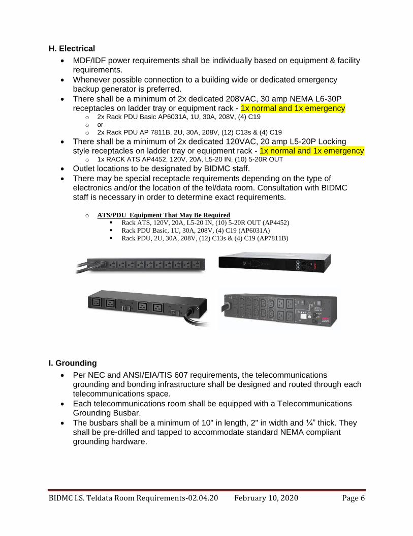
There shall be a minimum of 2x dedicated 208VAC, 30 amp NEMA L6-30P receptacles on ladder tray or equipment rack - 1x normal and 1x emergency
o 2x Rack PDU Basic AP6031A, 1U, 30A, 208V, (4) C19 o or o 2x Rack PDU AP 7811B, 2U, 30A, 208V, (12) C13s & (4) C19
There shall be a minimum of 2x dedicated 120VAC, 20 amp L5-20P Locking style receptacles on ladder tray or equipment rack - 1x normal and 1x emergency
o 1x RACK ATS AP4452, 120V, 20A, L5-20 IN, (10) 5-20R OUT
Outlet locations to be designated by BIDMC staff.
There may be special receptacle requirements depending on the type of electronics and/or the location of the tel/data room. Consultation with BIDMC staff is necessary in order to determine exact requirements.
o ATS/PDU Equipment That May Be Required
Rack ATS, 120V, 20A, L5-20 IN, (10) 5-20R OUT (AP4452)
Rack PDU Basic, 1U, 30A, 208V, (4) C19 (AP6031A)
Rack PDU, 2U, 30A, 208V, (12) C13s & (4) C19 (AP7811B)
I. Grounding
Per NEC and ANSI/EIA/TIS 607 requirements, the telecommunications grounding and bonding infrastructure shall be designed and routed through each telecommunications space.
Each telecommunications room shall be equipped with a Telecommunications Grounding Busbar.
The busbars shall be a minimum of 10" in length, 2" in width and ¼” thick. They shall be pre-drilled and tapped to accommodate standard NEMA compliant grounding hardware.
BIDMC I.S. Teldata Room Requirements-02.04.20 February 10, 2020 Page 7
J. Lighting
Lighting must have uniform intensity of 50 foot candles when measured 3 feet from the finished floor and must comply with BIDMC electrical standards.
Indirect lighting is not permitted.
Lighting shall be switched, without occupancy sensors.
Lighting fixtures must be on separate electrical circuits separate from the circuit the feeds the electrical outlets in the room.
Do not place light fixture above equipment racks to avoid blocking of light.
K. Sleeves and Conduits
Stacked closets shall be connected by four - 4" EMT sleeve conduits without offsets, for a clear cable pull.
All floor penetration sleeves shall extend 4 in. above and below the finished surface.
There should be a minimum of four - Horizontal 4" EMT sleeve conduits into telecommunications closet, location TBD by BIDMC staff
There shall be a minimum of three 2” conduits to the building D-Marc (Verizon, Comcast, etc.) from our MDF.
BIDMC I.S. Teldata Room Requirements-02.04.20 February 10, 2020 Page 8
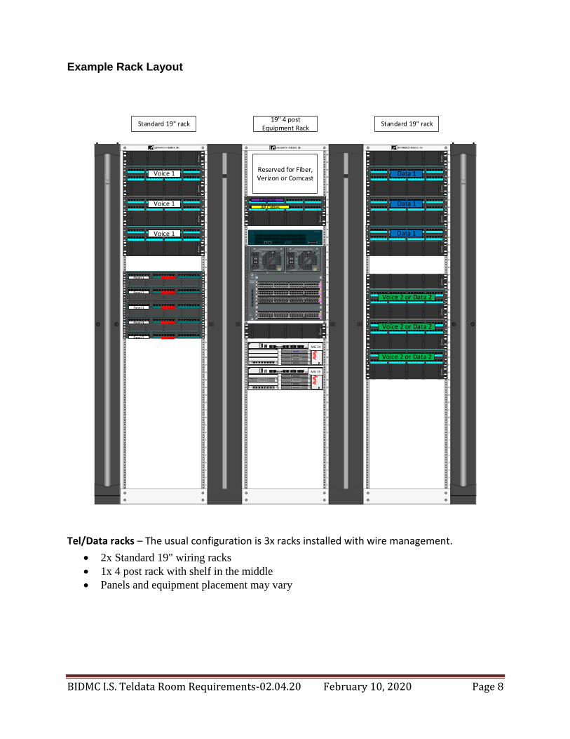
Example Rack Layout
19" 4 post
Equipment Rack
45
44
43
42
41
40
39
38
37
36
35
34
33
32
31
30
29
28
27
26
25
24
23
22
21
20
19
18
17
16
15
14
13
12
11
10
9
8
7
6
5
4
3
2
1
OR
TR
ON
ICS
O P
E N
S
Y S
T E
M
A R
C H
I T E
C T
U R
E
®
1 2 3 4 5 6 7 8 9 10 11 12 13 14 15 16 17 18 19 20 21 22 23 24
25 26 27 28 29 30 31 32 33 34 35 36 37 38 39 40 41 42 43 44 45 46 47 48
AP Cables
Cameras
Reserved for Fiber,Verizon or Comcast
OR
TR
ON
ICS
O P
E N
S
Y S
T E
M
A R
C H
I T E
C T
U R
E
FAN
STATUSS
UP
ER
VIS
OR
1
2
3
Catalyst
4506-E
4
5
6
WS-X4648-RJ45V-E“E”
SERIES
1
2
3
4
5
6
7
8
9
10
11
12
23
24
21
22
19
20
17
18
15
16
13
14
35
36
33
34
31
32
29
30
27
28
25
26
47
48
45
46
43
44
41
42
39
40
37
38POWER OVER
ETHERNET
IEEE 802.3
POE
STATUS
9 10 11 12
48-PORT
10/100/1000 BASE-T
POWER OVER ETHERNET 13 14 15 16 17 18 19 20 21 22 23
MULTI-SPEED
GIGABIT ETHERNET
SWITCHING MODULE24 25 26 27 28 29 30 31 32 33 34 35 36 37 38 39 40
POE
6000ACV
POE ENABLEDOUTPUT FAIL
FAN OK
INPUT 1OK
INPUT 2OK
O I
O I
SWITCHES SHOULD BE IN THE OFF ‘O’ POSITION TO INSTALL /REMOVE POWER SUPPLIES. FASTENERS MUST BE FULLY ENGAGED
PRIOR TO OPERATING POWER SUPPLY100-240V~ 12A
220-240V~ 16A 50/60 Hz
100-120V~ 12A/200-240V~ 16A (For Japan)
100-240V~ 12A
220-240V~ 16A 50/60 Hz
100-120V~ 12A/200-240V~ 16A (For Japan)
+V IN GND FB
ETR CCA ETH LANCONSOLE
V6V2
V1 V5
V4
V3
G450
V7
MDMALMCPUPWRS
YSTEM
RST ASB
USB ETH WANSERVICES
V8
ALM
TST
ACT
AVAYAMM 717
DIGITAL
ALM
TST
ACT
AVAYAMM 717
DIGITAL
ALM
TST
ACT
AVAYAMM 717
DIGITAL
ALM
TST
ACT
1 2 3 4 5 6 7 8
AVAYAMM 711
ANALOG
VHMPS
MG 34ALM
TST
ACT
AVAYAMM717
DIGITAL
ETR CCA ETH LANCONSOLE
V6V2
V1 V5
V4
V3
G450
V7
MDMALMCPUPWRS
YSTEM
RST ASB
USB ETH WANSERVICES
V8
ALM
TST
ACT
AVAYAMM 717
DIGITAL
ALM
TST
ACT
AVAYAMM 717
DIGITAL
ALM
TST
ACT
AVAYAMM 717
DIGITAL
ALM
TST
ACT
1 2 3 4 5 6 7 8
AVAYAMM 711
ANALOG
VHMPS
MG 35ALM
TST
ACT
AVAYAMM717
DIGITAL
ALM
TST
ACT
AVAYAMM716
ANALOG
Standard 19" rack
45
44
43
42
41
40
39
38
37
36
35
34
33
32
31
30
29
28
27
26
25
24
23
22
21
20
19
18
17
16
15
14
13
12
11
10
9
8
7
6
5
4
3
2
1
®
1 2 3 4 5 6 7 8 9 10 11 12 13 14 15 16 17 18 19 20 21 22 23 24
25 26 27 28 29 30 31 32 33 34 35 36 37 38 39 40 41 42 43 44 45 46 47 48
OR
TR
ON
ICS
O P
E N
S
Y S
T E
M
A R
C H
I T E
C T
U R
E
OR
TR
ON
ICS
O P
E N
S
Y S
T E
M
A R
C H
I T E
C T
U R
E
®
1 2 3 4 5 6 7 8 9 10 11 12 13 14 15 16 17 18 19 20 21 22 23 24
25 26 27 28 29 30 31 32 33 34 35 36 37 38 39 40 41 42 43 44 45 46 47 48
OR
TR
ON
ICS
O P
E N
S
Y S
T E
M
A R
C H
I T E
C T
U R
E
Voice 1
Voice 1
®
1 2 3 4 5 6 7 8 9 10 11 12 13 14 15 16 17 18 19 20 21 22 23 24
25 26 27 28 29 30 31 32 33 34 35 36 37 38 39 40 41 42 43 44 45 46 47 48
OR
TR
ON
ICS
O P
E N
S
Y S
T E
M
A R
C H
I T E
C T
U R
E
Voice 1
®®
®®
®
1 2 3 4 5 6 7 8 9 10 11 12 13 14 15 16 17 18 19 20 21 22 23 24
Panel 2 communication
®
1 2 3 4 5 6 7 8 9 10 11 12 13 14 15 16 17 18 19 20 21 22 23 24
Panel 3 communication
®
1 2 3 4 5 6 7 8 9 10 11 12 13 14 15 16 17 18 19 20 21 22 23 24
Panel 4communication
®
1 2 3 4 5 6 7 8 9 10 11 12 13 14 15 16 17 18 19 20 21 22 23 24
Panel 5communication
®
1 2 3 4 5 6 7 8 9 10 11 12 13 14 15 16 17 18 19 20 21 22 23 24
Panel 1 communication
45
44
43
42
41
40
39
38
37
36
35
34
33
32
31
30
29
28
27
26
25
24
23
22
21
20
19
18
17
16
15
14
13
12
11
10
9
8
7
6
5
4
3
2
1
Standard 19" rack
®
1 2 3 4 5 6 7 8 9 10 11 12 13 14 15 16 17 18 19 20 21 22 23 24
25 26 27 28 29 30 31 32 33 34 35 36 37 38 39 40 41 42 43 44 45 46 47 48
OR
TR
ON
ICS
O P
E N
S
Y S
T E
M
A R
C H
I T E
C T
U R
E
OR
TR
ON
ICS
O P
E N
S
Y S
T E
M
A R
C H
I T E
C T
U R
E
®
1 2 3 4 5 6 7 8 9 10 11 12 13 14 15 16 17 18 19 20 21 22 23 24
25 26 27 28 29 30 31 32 33 34 35 36 37 38 39 40 41 42 43 44 45 46 47 48
OR
TR
ON
ICS
O P
E N
S
Y S
T E
M
A R
C H
I T E
C T
U R
E
Voice 2 or Data 2
Voice 2 or Data 2
®
1 2 3 4 5 6 7 8 9 10 11 12 13 14 15 16 17 18 19 20 21 22 23 24
25 26 27 28 29 30 31 32 33 34 35 36 37 38 39 40 41 42 43 44 45 46 47 48
OR
TR
ON
ICS
O P
E N
S
Y S
T E
M
A R
C H
I T E
C T
U R
E
Voice 2 or Data 2
®
1 2 3 4 5 6 7 8 9 10 11 12 13 14 15 16 17 18 19 20 21 22 23 24
25 26 27 28 29 30 31 32 33 34 35 36 37 38 39 40 41 42 43 44 45 46 47 48
OR
TR
ON
ICS
O P
E N
S
Y S
T E
M
A R
C H
I T E
C T
U R
E
OR
TR
ON
ICS
O P
E N
S
Y S
T E
M
A R
C H
I T E
C T
U R
E
®
1 2 3 4 5 6 7 8 9 10 11 12 13 14 15 16 17 18 19 20 21 22 23 24
25 26 27 28 29 30 31 32 33 34 35 36 37 38 39 40 41 42 43 44 45 46 47 48
OR
TR
ON
ICS
O P
E N
S
Y S
T E
M
A R
C H
I T E
C T
U R
E
Data 1
Data 1
®
1 2 3 4 5 6 7 8 9 10 11 12 13 14 15 16 17 18 19 20 21 22 23 24
25 26 27 28 29 30 31 32 33 34 35 36 37 38 39 40 41 42 43 44 45 46 47 48Data 1
OR
TR
ON
ICS
O P
E N
S
Y S
T E
M
A R
C H
I T E
C T
U R
E
Tel/Data racks – The usual configuration is 3x racks installed with wire management.
2x Standard 19" wiring racks
1x 4 post rack with shelf in the middle
Panels and equipment placement may vary
BIDMC I.S. Teldata Room Requirements-02.04.20 February 10, 2020 Page 9
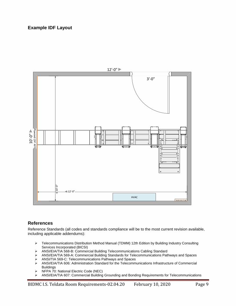
Example IDF Layout
12'-0"
10'-
0"
12'-0"10
'-0
"
HVAC
Ground
Plyw
oo
d (2
4' A
FF)
3'-0"
References
Reference Standards (all codes and standards compliance will be to the most current revision available, including applicable addendums):
Telecommunications Distribution Method Manual (TDMM) 12th Edition by Building Industry Consulting
Services Incorporated (BICSI) ANSI/EIA/TIA 568-B: Commercial Building Telecommunications Cabling Standard ANSI/EIA/TIA 569-A: Commercial Building Standards for Telecommunications Pathways and Spaces ANSI/TIA 569-C: Telecommunications Pathways and Spaces ANSI/EIA/TIA 606: Administration Standard for the Telecommunications Infrastructure of Commercial
Buildings NFPA 70: National Electric Code (NEC) ANSI/EIA/TIA 607: Commercial Building Grounding and Bonding Requirements for Telecommunications