Embed Size (px)
DESCRIPTION
Synchronous reluctance motor
Citation preview

9HSTFMG*afhcgc+
ISBN 978-952-60-5726-2 ISBN 978-952-60-5727-9 (pdf) ISSN-L 1799-4934 ISSN 1799-4934 ISSN 1799-4942 (pdf) Aalto University School of Electrical Engineering Department of Electrical Engineering and Automation www.aalto.fi
BUSINESS + ECONOMY ART + DESIGN + ARCHITECTURE SCIENCE + TECHNOLOGY CROSSOVER DOCTORAL DISSERTATIONS
Aalto-D
D 8
6/2
014
Modern synchronous reluctance motors are becoming viable competitors for induction motors in variable-speed drives due to smaller energy losses and simpler structure. In order to operate synchronous motors, information on the rotor position is needed. Position-acquicition methods which do not rely on mechanical sensors are often preferred, since mechanical sensors are expensive and prone to failures. In this thesis, three model-based position-estimation methods are analyzed and experimentally evaluated for synchronous reluctance motors. Since accuracy of the considered estimation methods depends on the equivalent-model parameters, further effort has been put on parameter-estimation methods which can be implemented during normal operation of the drive.
Toni T
uovinen M
odel-Based P
osition Estim
ation for Synchronous Reluctance M
otor Drives
Aalto
Unive
rsity
Department of Electrical Engineering and Automation
Model-Based Position Estimation for Synchronous Reluctance Motor Drives
Toni Tuovinen
DOCTORAL DISSERTATIONS
Aalto University publication series DOCTORAL DISSERTATIONS 86/2014
Model-Based Position Estimation for Synchronous Reluctance Motor Drives
Toni Tuovinen
A doctoral dissertation completed for the degree of Doctor of Science (Technology) to be defended, with the permission of the Aalto University School of Electrical Engineering, at a public examination held at the lecture hall S5 of the school on 20 August 2014 at 12.
Aalto University School of Electrical Engineering Department of Electrical Engineering and Automation Electric Drives
Supervising professors Prof. Jorma Luomi Prof. Marko Hinkkanen Thesis advisor Prof. Marko Hinkkanen Preliminary examiners Prof. Ion Boldea, University Politehnica, Timisoara, Romania Prof. Maarten Kamper, Stellenbosch University, Matieland, South Africa Opponent Prof. Gianmario Pellegrino, Politecnico di Torino, Torino, Italy
Aalto University publication series DOCTORAL DISSERTATIONS 86/2014 © Toni Tuovinen ISBN 978-952-60-5726-2 ISBN 978-952-60-5727-9 (pdf) ISSN-L 1799-4934 ISSN 1799-4934 (printed) ISSN 1799-4942 (pdf) http://urn.fi/URN:ISBN:978-952-60-5727-9 Unigrafia Oy Helsinki 2014 Finland
Abstract Aalto University, P.O. Box 11000, FI-00076 Aalto www.aalto.fi
Author Toni Tuovinen Name of the doctoral dissertation Model-Based Position Estimation for Synchronous Reluctance Motor Drives Publisher School of Electrical Engineering Unit Department of Electrical Engineering and Automation
Series Aalto University publication series DOCTORAL DISSERTATIONS 86/2014
Field of research Industrial Electronics and Electric Drives
Manuscript submitted 27 March 2014 Date of the defence 20 August 2014
Permission to publish granted (date) 13 May 2014 Language English
Monograph Article dissertation (summary + original articles)
Abstract This thesis deals with model-based position-estimation methods for synchronous reluctance
motor drives. The position estimation methods should be robust against modeling uncertainties, and reliable position information should be obtained at all speeds, including standstill. Since the considered position-estimation methods are model based, methods to obtain the model parameters under normal operation of the drive are proposed. Three observer structures are studied: a first-order observer, a reduced-order observer and a speed-adaptive full-order observer. The stability of the observers is studied via small-signal linearization under erroneous model parameters. Based on the analysis, robust gain selections are proposed with maximal tolerance for model parameter uncertainties. For improved performance, the observers are augmented with parameter adaptation laws. The first-order observer and the reduced-order observer are augmented with resistance adaptation laws at low speeds, using information from the back-electromotive force. The speed-adaptive full-order observer is augmented with inductance adaptation law at high speed, using information from the back-electromotive force. At low speeds, the speed-adaptive full-order observer is augmented with resistance adaptation law, using information from high-frequency signal injection. The stability of the augmented observers are studied via small-signal linearization under erroneous model parameters. Based on the analysis, stabilizing gain selections are proposed. The observers are experimentally evaluated using a 6.7-kW synchronous reluctance motor drive. The first-order observer seems unsuitable for these. The behaviour of the reduced-order observer is closely related to the behaviour of the speed-adaptive full-order observer, but the speed-adaptive full-order observer can be made less sensitive to parameter variations and measurement noise due to the additional degrees of freedom. When the speed-adaptive full-order observer is augmented with parameter-adaptation laws, small position-estimation error is obtained at all speeds, including standstill.
Keywords inductance adaptation, observer, parameter adaptation, sensorless, signal injection stability conditions, resistance adaptation, robustness
ISBN (printed) 978-952-60-5726-2 ISBN (pdf) 978-952-60-5727-9
ISSN-L 1799-4934 ISSN (printed) 1799-4934 ISSN (pdf) 1799-4942
Location of publisher Helsinki Location of printing Helsinki Year 2014
Pages 136 urn http://urn.fi/URN:ISBN:978-952-60-5727-9

Tiivistelmä Aalto-yliopisto, PL 11000, 00076 Aalto www.aalto.fi
Tekijä Toni Tuovinen Väitöskirjan nimi Reluktanssitahtimoottorikäyttöjen mallipohjainen asennon estimointi Julkaisija Sähkötekniikan korkeakoulu Yksikkö Sähkötekniikan ja automaation laitos
Sarja Aalto University publication series DOCTORAL DISSERTATIONS 86/2014
Tutkimusala Teollisuuselektroniikka ja sähkökäytöt
Käsikirjoituksen pvm 27.03.2014 Väitöspäivä 20.08.2014
Julkaisuluvan myöntämispäivä 13.05.2014 Kieli Englanti
Monografia Yhdistelmäväitöskirja (yhteenveto-osa + erillisartikkelit)
Tiivistelmä Tämä väitöskirja käsittelee mallipohjaisia menetelmiä reluktanssitahtimoottorikäyttöjen
roottorin asennon estimointiin. Estimointimenetelmien tulee olla robusteja mallin parametrivirheille, ja asentotiedon on oltava luotettava kaikilla nopeuksilla. Koska työssä tutkittavat estimointimenetelmät ovat mallipohjaisia, menetelmiä mallien parametrien ajonaikaiselle estimoinnille on ehdotettu. Työssä on tutkittu kolmea havaitsijarakennetta: ensimmäisen kertaluvun havaitsijaa, vähennetyn kertaluvun havaitsijaa ja adaptiivista täyden kertaluvun havaitsijaa. Havaitsijoiden stabiiliutta on tarkasteltu linearisoidulla piensignaalimallilla mallin parametrien ollessa virheellisiä. Analyysin pohjalta on johdettu havaitsijoiden vahvistuksille ehdot, jotka maksimoivat havaitsijoiden toleranssin parametrivirheille. Suorituskyvyn parantamiseksi havaitsijoita on laajennettu parametrien adaptointimekanismeilla. Pienillä nopeuksilla ensimmäisen kertaluvun havaitsijaa ja vähennetyn kertaluvun havaitsijaa laajennetaan resistanssin adaptointimekanismilla, joka pohjautuu vastasähkömotoriseen voimaan. Suurilla nopeuksilla täyden kertaluvun havaitsijaa laajennetaan vastasähkömotoriseen voimaan perustuvalla induktanssien adaptoinnilla. Pienillä nopeuksilla täyden kertaluvun havaitsijaa laajennetaan signaali-injektioon perustuvalla resistanssin adaptoinnilla. Laajennettujen havaitsijoiden stabiiliutta on tarkasteltu linearisoidulla piensignaalimallilla mallin parametrien ollessa virheellisiä. Analyysin pohjalta on johdettu havaitsijoiden vahvistuksille stabiilin toiminnan ehdot. Havaitsijoiden suorituskykyä on arvioitu kokeellisesti 6,7 kW:n reluktanssitahtimoottorikäytöllä. Tulosten perusteella ensimmäisen kertaluvun havaitsija soveltuu huonosti reluktanssitahtimoottoreille. Vähennetyn kertaluvun havaitsija on ominaisuuksiltaan lähellä adaptiivista täyden kertaluvun havaitsijaa, mutta ylimääräisten vapausasteiden vuoksi adaptiivinen täyden kertaluvun havaitsija on vähemmän herkkä parametrivirheille ja mittauskohinalle. Parametrien adaptointimekanismeilla laajennetulla adaptiivisella täyden kertaluvun havaitsijalla saavutetaan pieni estimointivirhe kaikilla nopeuksilla, myös nollanopeudella.
Avainsanat induktanssin adaptointi, havaitsija, parametrien adaptointi, anturiton, signaali-injektio, stabiiliusehdot, resistanssin adaptointi, robustius
ISBN (painettu) 978-952-60-5726-2 ISBN (pdf) 978-952-60-5727-9
ISSN-L 1799-4934 ISSN (painettu) 1799-4934 ISSN (pdf) 1799-4942
Julkaisupaikka Helsinki Painopaikka Helsinki Vuosi 2014
Sivumäärä 136 urn http://urn.fi/URN:ISBN:978-952-60-5727-9


Preface
This dissertation has been done at Aalto University, Department of Elec-
trical Engineering and Automation. The work has been financed by Doc-
toral Program in Electrical Energy Engineering (DPEEE) and ABB Oy, as
a part of an ongoing research project on electric drives.
I started this work under supervision of Prof. Jorma Luomi in 2010.
After the sudden demise of Prof. Luomi in 2011 the task of supervising
my work was assigned to Prof. Marko Hinkkanen, who was initially the
instructor of this work. They both contributed greatly on the writing and
outlining of this work, since explicit writing is not quite my forte. I am
more fond with equations.
The similar work done by Dr. Antti Piippo on permanent magnet syn-
chronous motors was of great help and served as a convenient starting
point. During the years, I have had several constructive advices, and
not only related to my work, from both the people working at ABB and
from the departmental staff, particularly from the personnel of the elec-
tric drives group.
There is always time for more coffee. Or beer.
Espoo, May 28, 2014,
Toni Tuovinen
1

Preface
2

Contents
Preface 1
Contents 3
List of Publications 5
Author’s Contribution 7
Symbols 9
1. Introduction 11
1.1 Background . . . . . . . . . . . . . . . . . . . . . . . . . . . . 11
1.2 Objective and Outline of the Thesis . . . . . . . . . . . . . . . 12
2. System Model 15
2.1 Fundamental Excitation Model . . . . . . . . . . . . . . . . . 15
2.2 High-Frequency Model . . . . . . . . . . . . . . . . . . . . . . 16
2.3 Magnetic Saturation . . . . . . . . . . . . . . . . . . . . . . . 17
2.4 Experimental Setup and Implementation . . . . . . . . . . . 18
3. Position Estimation 21
3.1 Current-Slope Methods . . . . . . . . . . . . . . . . . . . . . . 22
3.2 Fundamental-Excitation Methods . . . . . . . . . . . . . . . . 23
3.2.1 Voltage Models . . . . . . . . . . . . . . . . . . . . . . 23
3.2.2 Simple Observer . . . . . . . . . . . . . . . . . . . . . . 26
3.2.3 Reduced-Order Observer . . . . . . . . . . . . . . . . . 28
3.2.4 Speed-Adaptive Full-Order Observer . . . . . . . . . . 30
3.3 High-Frequency Signal-Injection Methods . . . . . . . . . . . 31
3.4 Combined Observers . . . . . . . . . . . . . . . . . . . . . . . 35
4. Parameter Adaptation 41
3

Contents
4.1 Stator-Resistance Adaptation Using Fundamental Excitation 41
4.2 Inductance-Adaptation Using Fundamental Excitation . . . 42
4.3 Stator-Resistance Adaptation Using High-Frequency Signal
Injection . . . . . . . . . . . . . . . . . . . . . . . . . . . . . . 43
5. Summaries of Publications 45
5.1 Abstracts . . . . . . . . . . . . . . . . . . . . . . . . . . . . . . 45
5.2 Contribution of the Thesis . . . . . . . . . . . . . . . . . . . . 47
6. Conclusions 49
Bibliography 51
Errata 55
Publications 57
4
List of Publications
This thesis consists of an overview and of the following publications which
are referred to in the text by their Roman numerals.
I M. Hinkkanen, T. Tuovinen, L. Harnefors, and J. Luomi. Analysis
and design of a position observer with stator-resistance adaptation
for PMSM drives. In International Conference on Electrical Machines
(ICEM’10), 6 pp., Rome, Italy, September 2010.
II T. Tuovinen, M. Hinkkanen, L. Harnefors, and J. Luomi. A reduced-
order position observer with stator-resistance adaptation for syn-
chronous reluctance motor drives. In International Power Electronics
and Motion Control Conference (EPE/PEMC 2010), 6 pp., Ohrid, Re-
public of Macedonia, September 2010.
III Z. Qu, T. Tuovinen and M. Hinkkanen. Inclusion of magnetic satu-
ration in dynamic models of synchronous reluctance motors. In Inter-
national Conference on Electrical Machines (ICEM’12), pp. 994-1000,
Marseille, France, September 2012.
IV T. Tuovinen, M. Hinkkanen, and J. Luomi. Analysis and design of a
position observer with resistance adaptation for synchronous reluctance
motor drives. IEEE Transactions on Industry Applications, vol. 49, is-
sue 1, pp. 66-73, January/February 2013.
V T. Tuovinen, M. Hinkkanen, L. Harnefors, and J. Luomi. Comparison
of a reduced-order observer and a full-order observer for sensorless syn-
5
List of Publications
chronous motor drives. IEEE Transactions on Industry Applications,
vol. 48, issue 6, pp. 1959-1967, November/December 2012.
VI T. Tuovinen and M. Hinkkanen. Adaptive full-order observer with
high-frequency signal injection for synchronous reluctance motor drives.
Accepted for publication in IEEE Journal of Emerging and Selected Top-
ics in Power Electronics, vol. 2, issue 2, pp. 181-189, June 2014.
VII T. Tuovinen and M. Hinkkanen. Signal-injection assisted full-order
observer with parameter adaptation for synchronous reluctance motor
drives. Accepted for publication in IEEE Transactions on Industry Ap-
plications, 12 pp., in press.
6

Author’s Contribution
Publication I: “Analysis and design of a position observer withstator-resistance adaptation for PMSM drives”
The author participated in the writing of the paper and performed the sta-
bility evaluations for synchronous reluctance motor drives. Prof. Harne-
fors contributed by commenting the manuscript.
Publication II: “A reduced-order position observer withstator-resistance adaptation for synchronous reluctance motordrives”
The author wrote the paper under the guidance of Prof. Hinkkanen
and Prof. Luomi. Prof. Harnefors contributed by commenting the
manuscript.
Publication III: “Inclusion of magnetic saturation in dynamic modelsof synchronous reluctance motors”
The author performed the measurements and participated in the writing
of the paper.
Publication IV: “Analysis and design of a position observer withresistance adaptation for synchronous reluctance motor drives”
The author wrote the paper under the guidance of Prof. Hinkkanen and
Prof. Luomi.
7

Author’s Contribution
Publication V: “Comparison of a reduced-order observer and afull-order observer for sensorless synchronous motor drives”
The author wrote the paper under the guidance of Prof. Hinkkanen
and Prof. Luomi. Prof. Harnefors contributed by commenting the
manuscript.
Publication VI: “Adaptive full-order observer with high-frequencysignal injection for synchronous reluctance motor drives”
The author wrote the paper under the guidance of Prof. Hinkkanen.
Publication VII: “Signal-injection assisted full-order observer withparameter adaptation for synchronous reluctance motor drives”
The author wrote the paper under the guidance of Prof. Hinkkanen.
8
Author’s Contribution
Symbols
I Identity matrix
ic High-frequency stator-current vector
icd High-frequency direct-axis stator-current component
icq High-frequency quadrature-axis stator-current component
id Direct-axis stator-current component
iq Quadrature-axis stator-current component
is Stator-current vector
J Orthogonal rotation matrix
K Observer gain matrix
k1 Observer gain
k11 Element of the observer gain matrix K
k12 Element of the observer gain matrix K
k2 Observer gain
k21 Element of the observer gain matrix K
k22 Element of the observer gain matrix K
ki Integral gain of the speed adaptation
kp Proportional gain of the speed adaptation
L Inductance matrix
Lc Incremental-inductance matrix
Ld Direct-axis inductance
Ldd Direct-axis self-incremental inductance
Ldq Direct-axis cross-incremental inductance
Lq Quadrature-axis inductance
Lqd Quadrature-axis cross-incremental inductance
Lqq Quadrature-axis self-incremental inductance
Rs Stator resistance
uc High-frequency stator-voltage vector
ucd Direct-axis stator-voltage component
ucq Quadrature-axis stator-voltage component
ud Direct-axis stator-voltage component
uq Quadrature-axis stator-voltage component
us Stator-voltage vector
9
Author’s Contribution
αlp Bandwidth of the low-pass filter
β Load parameter (β = iq/id)
γi Integral gain of the signal-injection PI-mechanism
γp Proportional gain of the signal-injection PI-mechanism
ε Position-error term in the signal-injection method
ϑm Mechanical angular position
ψs Stator flux linkage vector
ψd Direct-axis stator-flux component
ψq Quadrature-axis stator-flux component
ωc Angular frequency of the signal injection
ωε Speed-correction term in the signal-injection method
ωm Angular speed of the rotor
Bold, upper case letter denote matrices, and bold, lower case letters de-
note vectors. Symbols with circumflex denote estimates, and symbols with
tilde denote estimation errors.
10
1. Introduction
1.1 Background
Synchronous reluctance motors were long considered to be inferior to
other electrical motors [Kostko, 1923]. The recent design improvements
have increased the torque capabilities and energy efficiency of the syn-
chronous reluctance motors, and due to smaller energy losses modern
synchronous reluctance motors can produce 15–20% more torque than in-
duction motors of the same frame size [Boglietti and Pastorelli, 2008].
However, synchronous reluctance motors cannot be started directly from
the mains without additional rotor winding.
In order to minimize energy losses and to improve performance of the
system, electrical motors are fed with frequency converters in an increas-
ing trend. Utilization of frequency converters actualizes the possibility
of replacing the conventional induction motor with synchronous reluc-
tance motor in variable-speed drives. The structure of the synchronous
reluctance motor is simpler than that of the induction motor, and due to
smaller energy losses the efficiency of the synchronous reluctance motor
is larger. Simpler structure and smaller energy losses make synchronous
reluctance motors feasible competitors for induction motors.
Simple Volts-per-Hertz control may have unstable operating points
when applied for synchronous reluctance motors. Therefore, vector con-
trol or direct torque control is usually preferred. In these control methods,
information on the rotor position or on the flux angle is needed. The po-
sition can be either measured or estimated. Position-sensorless control
methods are often preferred, since the mechanical position encoders are
expensive and prone to failures. Moreover, in certain conditions mechani-
cal sensors cannot be installed.
Introduction
The position estimation can be based on the back-electromotive force
(back-EMF) induced by the rotational movement of the rotor. The ac-
curacy of these fundamental-excitation-based methods usually relies on
parameter-dependent equivalent-circuit models of the motor. Erroneous
parameter estimates result in erroneous position estimate, which impairs
the stability and performance of the drive. Furthermore, the back-EMF
decreases as the speed decreases, and the estimation becomes increas-
ingly sensitive to measurement and modeling errors.
The torque production in synchronous reluctance motors is based on
spatially varying reluctance of the rotor. Since the synchronous reluc-
tance motors are inherently salient, methods based on high-frequency ex-
citation can be used to detect the rotor position. Signal-injection methods,
however, inflict the system with additional noise and losses.
The magnetic circuit of the synchronous reluctance motors typically
saturates strongly under normal operation, i.e. the inductances of the
equivalent-circuit model depend on the operation point. Varying model
parameters cause inaccurate response, which is a research challenge in
sensorless control. Performance of the drive improves, when the satura-
tion is accounted for, and the saturation models can also be utilized in
loss-minimization control, for example. Although iron losses and inverter
nonlinearities also affect the performance of the drive, these phenomena
are not discussed in this thesis.
1.2 Objective and Outline of the Thesis
The objective of this thesis is to develop model-based position-estimation
methods for synchronous reluctance motor drives. The focus is on low-
and medium-speed operation of the drive. The estimation methods should
utilize only measurements available in a typical frequency converter and
guarantee stable operation under any practical speed and load conditions.
The realizable speed range should span from zero speed at least to the
rated speed, and the load range should span at least from zero load to
over the rated load. The estimation methods should be robust against
parameter variations caused by temperature changes and saturation.
Since the intended position-estimation methods are based on an
equivalent-circuit model of the motor, the further aim of this thesis is to
develop parameter-estimation methods which can be incorporated in the
position-estimation methods. The parameter-estimation methods should
12

Introduction
improve the performance of the drive and result in reliable parameter
estimates.
The thesis consist of this summary and seven publications. The
equivalent-circuit model of the motor, including magnetic saturation, and
the experimental setup are described in Chapter 2. Position-estimation
methods for synchronous reluctance motor drives are discussed in Chap-
ter 3. On-line parameter-estimation methods are discussed in Chapter 4.
The summaries of the publications and the contributions of the thesis are
listed in Chapter 5, and Chapter 6 concludes the thesis.
13

Introduction
14
2. System Model
2.1 Fundamental Excitation Model
The synchronous reluctance motor considered in this thesis is assumed to
be a symmetrical three-phase system, i.e. the sum of the phase voltages
and phase currents is zero. Hence, a two-axis model is sufficient to de-
scribe the behaviour of the system. In this thesis, real space vectors will
be used. For example, the stator-current vector in the stator-reference
frame is iss = [iα, iβ ]T, where iα and iβ are the orthogonal components of
the vector, the stator-reference frame is marked with the superscript s,
and the matrix transpose is marked with the superscript T. The space-
vector representation in the stator-reference frame is obtained from the
phase quantities, using Clarke transformation. For example, the stator-
current vector is obtained from the phase currents as
⎡⎣iαiβ
⎤⎦ =
⎡⎣2
3 −13 −1
3
0 1√3− 1√
3
⎤⎦⎡⎢⎢⎣ia
ib
ic
⎤⎥⎥⎦ . (2.1)
In order to simplify the analysis, the motor model will be expressed in
the estimated rotor reference frame, whose d-axis is aligned at ϑm with
respect to the stator-reference frame. The electrical position of the ac-
tual d-axis is denoted by ϑm. The d-axis is defined as the direction of the
maximum inductance of the rotor. The position depends on the electrical
angular rotor speed ωm according to
dϑm
dt= ωm. (2.2a)
The stator-current vector is rotated to the estimated rotor-reference
15
System Model
frame according to⎡⎣idiq
⎤⎦ = e−ϑmJ
⎡⎣iαiβ
⎤⎦ =
[cos(−ϑm)I+ sin(−ϑm)J
]⎡⎣iαiβ
⎤⎦ , (2.2b)
where the identity matrix and the orthogonal rotation matrix are defined
as
I =
⎡⎣1 0
0 1
⎤⎦ , J =
⎡⎣0 −11 0
⎤⎦ ,
respectively. Other space-vector quantities are rotated to the estimated
rotor-reference frame in a similar fashion.
The stator inductance is
L = e−ϑmJ
⎡⎣Ld 0
0 Lq
⎤⎦ eϑmJ, (2.2c)
where ϑm = ϑm − ϑm is the estimation error in the rotor position, Ld
the direct-axis inductance, and Lq the quadrature-axis inductance. The
voltage equation isdψs
dt= us −Rsis − ωmJψs, (2.2d)
where ψs is the stator-flux vector, us the stator-voltage vector, Rs the sta-
tor resistance, and ωm = dϑm/dt is the angular speed of the coordinate
system. The stator current is a nonlinear function
is = L−1ψs (2.2e)
of the stator-flux vector and the position-estimation error ϑm.
2.2 High-Frequency Model
The high-frequency voltage model is
dψc
dt= uc −Rsic − ωmJψc, (2.3)
where ψc is the high-frequency stator-flux vector, uc is the high-frequency
stator-voltage vector, and ic is the high-frequency stator-current vector.
The incremental-inductance matrix is
Lc = e−ϑmJ
⎡⎣Ldd Ldq
Lqd Lqq
⎤⎦ eϑmJ, (2.4)
where the incremental inductances seen by the high-frequency excitation
are
Ldd =∂ψd
∂id, Ldq =
∂ψd
∂iq, Lqd =
∂ψq
∂id, Lqq =
∂ψq
∂iq. (2.5)
16
System Model
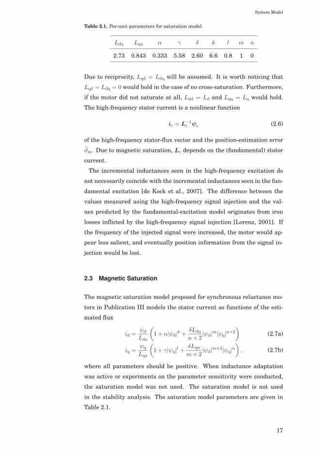
Table 2.1. Per-unit parameters for saturation model.
Ldu Lqu α γ δ k l m n
2.73 0.843 0.333 5.58 2.60 6.6 0.8 1 0
Due to reciprocity, Lqd = Ldq will be assumed. It is worth noticing that
Lqd = Ldq = 0 would hold in the case of no cross-saturation. Furthermore,
if the motor did not saturate at all, Ldd = Ld and Lqq = Lq would hold.
The high-frequency stator current is a nonlinear function
ic = L−1c ψc (2.6)
of the high-frequency stator-flux vector and the position-estimation error
ϑm. Due to magnetic saturation, Lc depends on the (fundamental) stator
current.
The incremental inductances seen in the high-frequency excitation do
not necessarily coincide with the incremental inductances seen in the fun-
damental excitation [de Kock et al., 2007]. The difference between the
values measured using the high-frequency signal injection and the val-
ues predicted by the fundamental-excitation model originates from iron
losses inflicted by the high-frequency signal injection [Lorenz, 2001]. If
the frequency of the injected signal were increased, the motor would ap-
pear less salient, and eventually position information from the signal in-
jection would be lost.
2.3 Magnetic Saturation
The magnetic saturation model proposed for synchronous reluctance mo-
tors in Publication III models the stator current as functions of the esti-
mated flux
id =ψd
Ldu
(1 + α|ψd|k + δLdu
n+ 2|ψd|m|ψq|n+2
)(2.7a)
iq =ψq
Lqu
(1 + γ|ψq|l + δLqu
m+ 2|ψd|m+2|ψq|n
), (2.7b)
where all parameters should be positive. When inductance adaptation
was active or experiments on the parameter sensitivity were conducted,
the saturation model was not used. The saturation model is not used
in the stability analysis. The saturation model parameters are given in
Table 2.1.
17
System Model
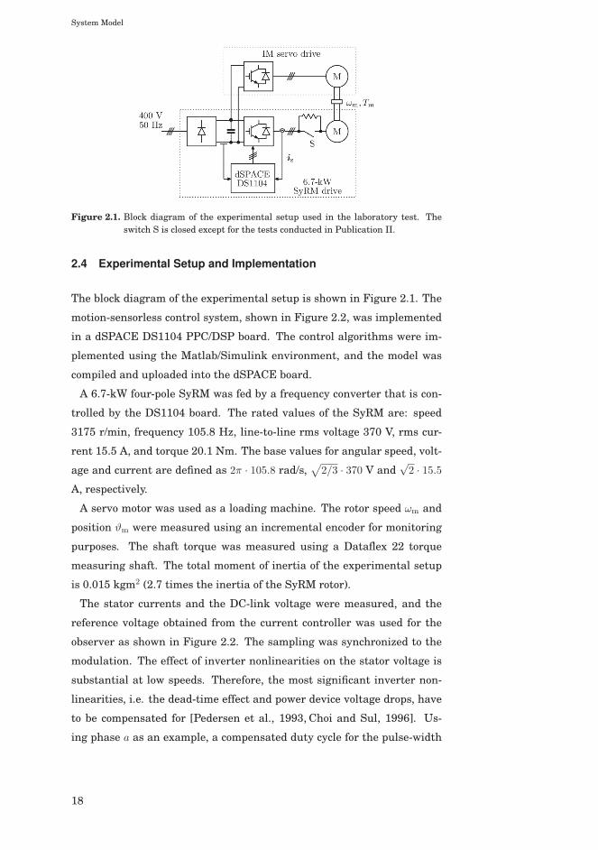
Figure 2.1. Block diagram of the experimental setup used in the laboratory test. Theswitch S is closed except for the tests conducted in Publication II.
2.4 Experimental Setup and Implementation
The block diagram of the experimental setup is shown in Figure 2.1. The
motion-sensorless control system, shown in Figure 2.2, was implemented
in a dSPACE DS1104 PPC/DSP board. The control algorithms were im-
plemented using the Matlab/Simulink environment, and the model was
compiled and uploaded into the dSPACE board.
A 6.7-kW four-pole SyRM was fed by a frequency converter that is con-
trolled by the DS1104 board. The rated values of the SyRM are: speed
3175 r/min, frequency 105.8 Hz, line-to-line rms voltage 370 V, rms cur-
rent 15.5 A, and torque 20.1 Nm. The base values for angular speed, volt-
age and current are defined as 2π · 105.8 rad/s,√2/3 · 370 V and
√2 · 15.5
A, respectively.
A servo motor was used as a loading machine. The rotor speed ωm and
position ϑm were measured using an incremental encoder for monitoring
purposes. The shaft torque was measured using a Dataflex 22 torque
measuring shaft. The total moment of inertia of the experimental setup
is 0.015 kgm2 (2.7 times the inertia of the SyRM rotor).
The stator currents and the DC-link voltage were measured, and the
reference voltage obtained from the current controller was used for the
observer as shown in Figure 2.2. The sampling was synchronized to the
modulation. The effect of inverter nonlinearities on the stator voltage is
substantial at low speeds. Therefore, the most significant inverter non-
linearities, i.e. the dead-time effect and power device voltage drops, have
to be compensated for [Pedersen et al., 1993, Choi and Sul, 1996]. Us-
ing phase a as an example, a compensated duty cycle for the pulse-width
18
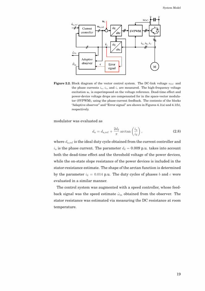
System Model
Figure 2.2. Block diagram of the vector control system. The DC-link voltage uDC andthe phase currents ia, ib, and ic are measured. The high-frequency voltageexcitation uc is superimposed on the voltage reference. Dead-time effect andpower-device voltage drops are compensated for in the space-vector modula-tor (SVPWM), using the phase-current feedback. The contents of the blocks“Adaptive observer” and “Error signal” are shown in Figures 4.1(a) and 4.1(b),respectively.
modulator was evaluated as
da = da,ref +2dδπ
arctan
(iaiδ
), (2.8)
where da,ref is the ideal duty cycle obtained from the current controller and
ia is the phase current. The parameter dδ = 0.009 p.u. takes into account
both the dead-time effect and the threshold voltage of the power devices,
while the on-state slope resistance of the power devices is included in the
stator-resistance estimate. The shape of the arctan function is determined
by the parameter iδ = 0.014 p.u. The duty cycles of phases b and c were
evaluated in a similar manner.
The control system was augmented with a speed controller, whose feed-
back signal was the speed estimate ωm obtained from the observer. The
stator resistance was estimated via measuring the DC resistance at room
temperature.
19

System Model
20
3. Position Estimation
Since simple Volts-per-Hertz control may have unstable operating points
when applied for synchronous reluctance motors [Lipo and Krause, 1967,
Cruickshank et al., 1971], field-oriented control is usually preferred in
order to achieve higher stability and performance. Field-oriented control
requires information on the rotor position or on the flux angle. Although
some authors favour stator-flux-oriented control [Kreindler et al., 1993,
Lagerquist et al., 1994, Inoue et al., 2010], it was suggested in [Vagati
et al., 1997] that the most robust choice for the controllable variables is
the d-axis flux ψd and the q-axis current iq, which requires information on
the rotor position.
A variety of different methods have been proposed in order to esti-
mate the stator flux angle or the rotor position. The different estima-
tion methods can be roughly divided into two categories: methods which
directly utilize the switching states of the frequency converters and meth-
ods which are based on the average (effective) voltage of the frequency
converter during a switching period. In this thesis, the focus is on meth-
ods which are based on the average voltage during pulse-width modula-
tion.
The methods which are based on the average voltage can be roughly
divided into two categories: fundamental-excitation methods and signal-
injection methods. The methods based on the fundamental excitation
(back-electromotive force, back-EMF) are relatively simple and provide
satisfactory accuracy at medium and high speeds. However, the back-
EMF decreases as the speed decreases, and the disrupting effects of mod-
eling errors and system noise increase, which may render the back-EMF
methods inoperable at low speeds.
Due to the inherent saliency of the synchronous reluctance motors,
methods based on high-frequency excitation can be used to detect the ro-
Position Estimation
tor position at all speed, including standstill. Because the signal-injection
methods inflict the system with additional noise and losses, combined ap-
proaches can be used. These rely on signal injection near standstill, and
back-EMF-based methods dominate at higher speeds.
In this thesis, three back-EMF-based observer structures, with increas-
ing complexity, are investigated for rotor-position estimation. Since the
investigated estimation methods are model based, the accuracy and sta-
bility of the drive depends on the accuracy of the equivalent-circuit model
parameters. For improved performance, the main focus has been on
stability analysis with uncertain model parameter estimates. Speed-
estimation methods have been briefly addressed with the related position-
estimation methods. If the drive is operated in torque-control mode, speed
estimation is not mandatory.
3.1 Current-Slope Methods
The estimation methods which rely on the behaviour of the system during
switching states of the frequency converter are natural choices for direct
torque controlled (DTC) drives. These methods are based on measuring
the slopes of the phase currents during switching states. In [Matsuo and
Lipo, 1995], the position information is extracted from the current ripples
in hysteresis current control. The method requires look-up tables for the
rate of change of the currents as functions of the position. Similar ap-
proaches have been addressed in [Xiang and Nasar, 1995] and [Jovanovic
et al., 1998]. In the latter case, the quality of the speed estimate is im-
proved using an angular velocity observer introduced in [Lorenz and Pat-
ten, 1991].
In order to eliminate the need for preliminary measurements, the
method proposed in [Schroedl and Weinmeier, 1994] applies test-voltage
injections in two different directions, and the position information can be
extracted from the measured currents without voltage measurements or
knowledge of the motor parameters. However, since the quality of this
position-estimation method declines as the rotational speed increases, a
back-EMF-based observer is used at high speeds. Since the direct calcu-
lation of position and speed from measured currents results in noisy esti-
mates, Kalman filters have been applied in order to obtain usable position
and speed estimates.
The method has been further improved to cover the entire operation
22
Position Estimation
range in [Chen et al., 2004] and [Wei and Liu, 2012], using single and
dual current-slope techniques, respectively, without additional test sig-
nals. Similar approaches for DTC drives have been proposed in [Morales-
Caporal and Pacas, 2008], where additional test voltage signals are in-
jected during zero voltage of DTC, and in [Landsmann et al., 2010a],
where normal operation of predictive DTC is utilized.
3.2 Fundamental-Excitation Methods
3.2.1 Voltage Models
The most important system state in the field-oriented control is the rotor
position (or the flux angle). Various approaches have been proposed to
extract the position information from the back-EMF, of which some meth-
ods require information on the equivalent-circuit model parameters. Sim-
plest methods rely directly on current or voltage measurements, without
knowledge on the model parameters.
A simple model-independent approach was introduced in [Kreindler
et al., 1993], where the position information was obtained via tracking the
zero crossings of the third harmonic of the phase voltages in a saturated
motor. The method, however, requires access to the neutral point, which
is not always available. Somewhat related approach was used in [Arefeen
et al., 1994], where the current in one phase was kept at zero after zero
crossing and test signals were injected to the other phases. The voltage
induced to the phase with current kept at zero was measured, and the
position was determined based on a look-up table. Both these methods
provide effectively only six position samples per electrical cycle, which
leads to only moderate performance.
A simple model-dependent position-estimation method was introduced
in [Stumper et al., 2010]. The method is based on calculating the rotor
position directly from instantaneous voltages and currents. The method
provides directly only position estimates between −π/4 and 3π/4. Thus, a
low-pass filter is used in order to extend the estimator range to cover the
entire operation range,
dϑm
dt= −α
[(ϑm mod π)− ϑ′
m
], (3.1)
where α is the position-estimation bandwidth, ϑ′m is the position informa-
tion from the direct estimation, mod is the modulo operation, and ϑm is
23
Position Estimation
the usable position information. The necessary parameters used in this
method are the stator resistance and the average stator inductance.
In [Lagerquist et al., 1994], the stator-flux estimate was obtained via
integrating the voltage equation in the stator-reference frame,
dψs
s
dt= us
s − Rsiss, (3.2)
where Rs is the stator-resistance estimate. The flux angle was extracted
from the estimated flux components
ϑ = arctan
(ψβ
ψα
), (3.3)
where ψα and ψβ are the estimated stator-flux components in the stator-
reference frame. No information on the rotor position is available. The
speed estimate was obtained directly from the flux angle estimate as
ωm =dϑ
dt. (3.4)
In transient states, this leads to poor speed-estimation dynamics. Hence,
the torque dynamics has to be limited if reliable speed estimation is de-
sired. Similar approach to estimate the stator flux at high speeds was
used in [Ha et al., 1999], where the rotor position is estimated from the
flux angle as
ϑm = arctan
(ψβ
ψα
)− arctan
(Lqiq
Ldid
), (3.5)
where Ld and Lq are the direct-axis and quadrature-axis inductance esti-
mates, respectively.
Due to measurement noise and bias, the pure voltage integration with-
out corrections as in (3.2) is prone to drift. A simple improvement is
to replace the pure integration with low-pass filters as in [Ghaderi and
Hanamoto, 2011]. Another approach is to introduce a feedback to the volt-
age integration. Different feedback methods have been used in [Capecchi
et al., 2001] and [Agarlita et al., 2012], for example, which are both based
on measured behaviour of the stator flux as function of the stator current,
i.e. ψs = ψs(is). In [Capecchi et al., 2001], the stator flux is estimated as
dψsu
s
dt= us
s − Rsiss + g
(ψ
si
s − ψsu
s
), (3.6)
where ψsi
s is based on the measured behaviour of ψs(is) and g is a de-
sign parameter associated with the crossover frequency between the pure
24
Position Estimation
voltage integration and the current based model ψsi
s . The slightly differ-
ent approach in [Agarlita et al., 2012] introduces a compensation voltage
vector
vc = kpψs +
∫kiψsdt, (3.7)
where kp and ki are adaptation gains and ψs = ψsu
s − ψsi
s . The compensa-
tion voltage vector is incorporated in the voltage integration
dψsu
s
dt= us
s − Rsiss + vc. (3.8)
In both these approaches, the flux estimation is dominated by the mea-
sured ψs(is) characteristics at low speeds, and the pure voltage integra-
tion dominates at high speeds. Since the ψs(is) characteristics are deter-
mined in the dq-frame, a rotor-position estimate is required. In [Capec-
chi et al., 2001], the trigonometric functions needed for the coordinate
transformation were calculated utilizing the flux estimates both in the
αβ-frame and the dq-frame,
sin ϑm =ψdψβ − ψαψq
ψ2s
, cos ϑm =ψdψα + ψβψq
ψ2s
, (3.9)
where ψs is the magnitude of the estimated stator flux. The speed esti-
mate was obtained directly from the time derivatives of cos ϑm and sin ϑm,
ωm = cos ϑmd sin ϑm
dt− sin ϑm
d cos ϑm
dt, (3.10)
while the final speed and position estimation from the noisy flux estimates
in [Agarlita et al., 2012] was based on the work presented in [Lorenz and
Patten, 1991].
The approach used in [Ichikawa et al., 2003] was based on the extended-
EMF (EEMF) concept. Only the EEMF part of the voltage equation de-
pends on the rotor position,
ve = (Ld − Lq)
(ωmid − diq
dt
)⎡⎣− sin(ϑm)
cos(ϑm)
⎤⎦ . (3.11)
The EEMF was estimated using a reduced-order observer, and the rotor
position estimate was extracted directly from the estimated EEMF,
ϑm = arctan
(−ve,αve,β
). (3.12)
The speed was estimated using an adaptive velocity estimator based on
the work presented in [Tomita et al., 1998].
25
Position Estimation
Slightly different approach used in [Landsmann et al., 2010b] was based
on estimating only the position-dependent part of the stator flux
ψsΔ =
Ld − Lq
2
⎡⎣cos(2ϑm) sin(2ϑm)
sin(2ϑm) − cos(2ϑm)
⎤⎦ iss. (3.13)
Feedback from the estimated position-dependent flux component was
used to compensate the integration drift,
ψs
Δ =
∫ (uss − Rsi
ss − kdψ
s
Δ
)dt− Ld + Lq
2iss, (3.14)
where kd is the feedback gain. The position-estimation error was obtained
from the cross product
ε =(ψ
s
Δ
)TJψ
si
Δ, (3.15)
where ψsi
Δ is based on the measured behaviour of ψs(is). The error signal
ε was driven to zero with a PI-mechanism.
3.2.2 Simple Observer
The simple observer considered in Publication I for permanent-magnet
synchronous motor drives is derived by expressing the back-EMF in two
different ways. For synchronous reluctance motors, these can be ex-
pressed as
e = ωmJLis (3.16a)
e′ = us − Rsis − Ldisdt
, (3.16b)
where the model inductance matrix is
L =
⎡⎣Ld 0
0 Lq
⎤⎦ . (3.17)
The observer is composed from (3.16) as
kT(e− e′) = 0, (3.18)
where k = [g, 1]T is a projection vector and g is the observer gain. The
speed estimate can be solved as
ωm =kT (us − Rsis − Ldis
dt )
kTJLis. (3.19)
In component form, this gives
ωm =uq − Rsiq − Lq
diqdt + g(ud − Rsid − Ld
diddt )
Ldid − gLqiq. (3.20)
26
Position Estimation
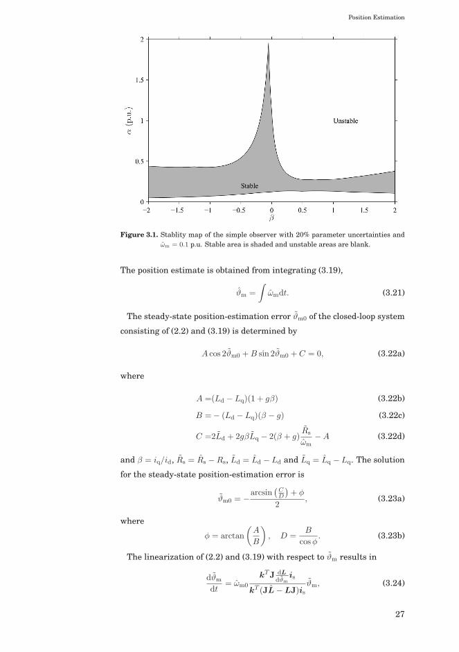
Figure 3.1. Stablity map of the simple observer with 20% parameter uncertainties andωm = 0.1 p.u. Stable area is shaded and unstable areas are blank.
The position estimate is obtained from integrating (3.19),
ϑm =
∫ωmdt. (3.21)
The steady-state position-estimation error ϑm0 of the closed-loop system
consisting of (2.2) and (3.19) is determined by
A cos 2ϑm0 +B sin 2ϑm0 + C = 0, (3.22a)
where
A =(Ld − Lq)(1 + gβ) (3.22b)
B =− (Ld − Lq)(β − g) (3.22c)
C =2Ld + 2gβLq − 2(β + g)Rs
ωm−A (3.22d)
and β = iq/id, Rs = Rs −Rs, Ld = Ld − Ld and Lq = Lq − Lq. The solution
for the steady-state position-estimation error is
ϑm0 = −arcsin
(CD
)+ φ
2, (3.23a)
where
φ = arctan
(A
B
), D =
B
cosφ. (3.23b)
The linearization of (2.2) and (3.19) with respect to ϑm results in
dϑm
dt= ωm0
kTJ dLdϑm
is
kT (JL−LJ)isϑm, (3.24)
27
Position Estimation
where ωm0 is the steady-state operating-point value of ωm. This can be
expressed in the formdϑm
dt= −αϑm, (3.25)
where α is the position-estimation bandwidth. With accurate parameter
estimates, the observer gain selection can be expressed as
g =βωm − α
βα+ ωm. (3.26)
As the load varies, it is difficult to choose α in such a way that the gain
g remains small, i.e. |βα + ωm| is sufficiently larger than zero, and at the
same time has relatively fast position estimation.
The robustness of the simple observer is studied using the linearized
estimation-error dynamics given in (3.24) after the steady-state estima-
tion error was solved using (3.23). The steady-state operation with β vary-
ing from −2 to 2 at ωm0 = 0.1 p.u. was considered. The actual parameters
correspond to those of the 6.7-kW SyRM: Ld = 2.00 p.u., Lq = 0.3 p.u. and
Rs = 0.042 p.u. The same relative uncertainty (20%) is assumed for all
three model parameters Ld, Lq and Rs. Hence, eight different worst-case
combinations, consisting of minimum and maximum values of the model
parameters, can be formed. For example, one of the worst-case combina-
tions is Ld = 0.8Ld, Lq = 1.2Lq and Rs = 0.8Rs. At each studied operating
point, the local stability of the system was analyzed for all eight worst-
case combinations of erroneous model parameters.
The stability of the estimation-error dynamics with erroneous model pa-
rameters was tested for different values of the design parameter α. The
stability map is depicted in Figure 3.1, where the stable area is shaded
and the unstable areas are blank. It can be seen that the stable region
in the motoring mode is very narrow, particularly near β = 0.5. Due to
high sensitivity to parameter errors and difficulties in gain selection, the
method was deemed insufficient for synchronous reluctance motor drives.
3.2.3 Reduced-Order Observer
The reduced-order observer considered in Publication II consists of esti-
mating the d-axis flux component together with the rotor position,
dψd
dt= ud − Rsid + ωmLqiq + k1(ψd − Ldid) (3.27a)
dϑm
dt=
uq − Rsiq − Lqdiqdt + k2(ψd − Ldid)
ψd
= ωm, (3.27b)
28
Position Estimation
where k1 and k2 are observer gains. The observer utilizes feedback from
the flux-estimation error in the d-axis direction only. The nonlinear es-
timation error dynamics of the closed-loop system consisting of (2.2) and
(3.27) are
dψs
dt= (KL
−1 − ωmJ)ψs +[K(L
−1L− I)− Rs
]is, (3.28a)
where ψs = ψs − ψs and the gain matrix K utilizes the flux-estimation
error only in the d-axis direction in accordance with (3.27),
K =
⎡⎣k1Ld 0
k2Ld 0
⎤⎦ . (3.28b)
The gains are scaled with Ld in order to simplify the notation in the fol-
lowing analysis.
The error of the q-axis flux is a nonlinear function of the position-
estimation error, since ψq = Lqiq and
ψq =iq2(Ld + Lq)− id
2(Ld − Lq)
[sin(2ϑm) + β cos(2ϑm)
], (3.28c)
which can be obtained from (2.2e).
The steady-state position-estimation error is determined by
A cos 2ϑm0 +B sin 2ϑm0 + C = 0, (3.29a)
where
A =(Ld − Lq) [β(k2 − ωm0)− k1] (3.29b)
B =(Ld − Lq) [(k2 − ωm0) + βk1] (3.29c)
C =2k1Ld + 2β(k2 − ωm0)Lq − 2 (k2 − ωm0 − βk1)Rs
ωm0−A. (3.29d)
The solution for the steady-state position-estimation error is obtained in
a fashion similar to (3.23).
After the steady-state estimation errors have been solved, (3.28a) is lin-
earized in the vicinity of these steady-state errors, which yields
d
dt
⎡⎣ψd
ψq
⎤⎦=⎡⎣ k1 ωm0 − k1β
′
k2 − ωm0 −k2β′
⎤⎦⎡⎣ψd
ψq
⎤⎦ , (3.30)
where
β′ = tan(2ϑm0 + arctanβ). (3.31)
The characteristic polynomial of (3.30) is
s2 + b′s+ c′, (3.32)
29
Position Estimation
where
b′ = k2β′ − k1 (3.33a)
c′ = ω2m0 − ωm0
(k2 + k1β
′) . (3.33b)
In order to stabilize the system, b′ and c′ should be positive.
If accurate motor parameters are assumed, then the gains k1 and k2 can
be solved from (3.33) as functions of the coefficients of the characteristic
polynomial b′ = b and c′ = c. The coefficients b and c can be regarded as
design parameters, and the gains are
k1 = −b+ β(c/ωm − ωm)
β2 + 1, k2 =
βb− c/ωm + ωm
β2 + 1. (3.34)
With accurate parameter estimates, the system is stable for all positive
values of b and c.
It was pointed out in Publication IV and Publication V that the reduced-
order observer is relatively sensitive to harmonic noise and parameter
uncertainties. Hence, a speed-adaptive full-order observer was considered
in Publication VI and Publication VII.
3.2.4 Speed-Adaptive Full-Order Observer
In the speed-adaptive full-order observer, the stator-flux vector is esti-
mated according to
dψs
dt= us − Rsis − ωmJψs +Kis (3.35a)
is = L−1
ψs, (3.35b)
where is = is − is. In order to simplify the analysis, the observer gain
matrix is written –without loss of generality– as
K =
⎡⎣Rs + Ldk11 Lqk12
Ldk21 Rs + Lqk22
⎤⎦ . (3.35c)
The rotor speed is adapted using the PI-mechanism
ωm = kpiq +
∫kiiqdt, (3.35d)
and the rotor position is obtained according to (3.21).
Since the speed-adaptation law drives iq to zero, the adaptation gains kp
and ki do not affect the position-estimation error in the steady state, and
the equation for the steady-state position-estimation error is the same as
for the reduced-order observer, i.e. (3.29).
30
Position Estimation
If the gains k12 and k22 in (3.35c) are selected according to
k12 = −βk11 (3.36a)
k22 = −βk21 (3.36b)
then with accurate parameter estimates the dynamics of the speed-
adaptation loop are disconnected from the dynamics of the flux observer.
Furthermore, if the speed-adaptation gains are selected as
kp =Lqd
(Ld − Lq)id, ki =
Lqe
(Ld − Lq)id(3.37)
and the flux-observer gains are selected as
k11 = k1, k21 = k2, (3.38)
where k1 and k2 are defined in (3.34), the characteristic polynomial of the
linearized closed-loop system consisting of (2.2) and (3.35) can be written
as
(s2 + bs+ c)(s2 + ds+ e). (3.39)
The design parameters b and c are associated with the flux observer, and
the design parameters d and e are associated with the speed-adaptation
loop. Ideally, the poles of the flux observer can be placed independently of
the speed adaptation.
3.3 High-Frequency Signal-Injection Methods
The inherently salient structure of synchronous reluctance motors makes
it naturally suitable for signal-injection methods. In signal-injection
methods, a high-frequency voltage (or current) excitation is superimposed
on the back-EMF.
The most common excitation signals are alternating excitation and ro-
tating excitation, while other excitation signals can be used as well. For
example, the low-speed position estimation in [Ichikawa et al., 2003] is
based on recursive system-parameter identification with M-sequence ex-
citation. Although some authors favour rotating excitation [Jansen and
Lorenz, 1995,Consoli et al., 1999,Agarlita et al., 2012], the benefits of this
approach compared to alternating excitation have been inconclusive [Raca
et al., 2008]. The alternating excitation is less sensitive to inverter dead-
time [Raca et al., 2008], while the rotating injection may be advantageous
if the motor has multiple saliencies [Degner and Lorenz, 1998].
31
Position Estimation
A simple position-estimation method was introduced in [Consoli et al.,
2007], where a high-frequency voltage excitation was superimposed on
the stator voltage in the estimated d-axis direction. The magnitude of
the high-frequency current response in the q-axis direction was tracked.
A minimum-search algorithm was applied to vary the injection direction
in such a way that the magnitude of the q-axis high-frequency current
would be minimized. This method can be regarded as an improvement
of the method proposed in [Consoli et al., 1999], where a rotating voltage
injection was used and the position information was determined from the
occurrence of the minimum high-frequency current. The speed estimate
used in the speed-control loop was obtained from the PI-based mechanism
ωm =
∫kJεdt (3.40a)
ε = kTeTe + kp
(dϑ
dt− ωm
)+ ki
(ϑ−
∫ωmdt
), (3.40b)
where ϑ is the estimated position, Te is the estimated electromagnetic
torque and kJ and kTe are adaptation gains corresponding to the inertia
and electromagnetic torque, respectively.
A high-frequency current excitation was applied in [Kang et al., 1999]. A
current excitation of the same magnitude was superimposed on the stator
current in both the d- and q-axis direction
ic =
⎡⎣ic cos(ωct)
ic sin(ωct)
⎤⎦ , (3.41)
where ic is the magnitude of the injected current and ωc is the injection
angular frequency. The position-estimation error is extracted from the
induced high-frequency voltage responses, which were demodulated and
low-pass filtered (LPF)
Δϑ ≈ LPF {ucd cos(ωct)− ucq sin(ωct)}(Ld − Lq)(ωc + ωm)ic
, (3.42)
where ucd and ucq are the d- and q-axis components of the induced high-
frequency voltage responses, respectively. The position-estimation error
Δϑ is then used to directly update the position estimate. The estimated
speed is obtained from the time derivative of the position estimate.
The signal-injection method used in this thesis utilizes alternating high-
frequency voltage excitation in the estimated d-axis direction [Corzine
et al., 1998],
uc =
⎡⎣uc cos(ωct)
0
⎤⎦ , (3.43)
32
Position Estimation
where uc is the magnitude of the voltage excitation.
If the rotational speed and the resistive voltage drop are omitted, the
high-frequency current responses are
icd =uc sin(ωct)
ωcLdet
[LΣ − LΔ cos(2ϑm)− Ldq sin(2ϑm)
](3.44a)
icq =uc sin(ωct)
ωcLdet
[LΔ sin(2ϑm)− Ldq cos(2ϑm)
], (3.44b)
where
Ldet = LddLqq − L2dq (3.45a)
LΣ =Ldd + Lqq
2(3.45b)
LΔ =Ldd − Lqq
2. (3.45c)
The position information is extracted from the current responses via de-
modulation and low-pass filtering [Harnefors and Nee, 2000, Villet et al.,
2012]. Conventionally, only the high-frequency current component per-
pendicular to the injected signal is used in the position estimation,
ε = LPF {iq sin(ωct)}≈ uc
2ωcLdet
[LΔ sin(2ϑm)− Ldq cos(2ϑm)
].
(3.46)
Usually, signal-injection based position estimation is designed to find a di-
rection where ε = 0. Due to cross-saturation, this straightforward scheme
(3.46) leads to a steady-state position-estimation error [Guglielmi et al.,
2006]
ϑm0 =1
2arctan
(Ldq
LΔ
). (3.47)
The method proposed in Publication VI to compensate the position-
estimation error caused by the cross-saturation is to use a combination
of the d- and q-axis current components, which is demodulated and low-
pass filtered,
ε = LPF
{(Ldq
Lqq
id + iq
)sin(ωct)
}
≈ − uc
2ωcLdetLqq
(LdqLqq + LdqLΔ
)cos(2ϑm)
+uc
2ωcLdetLqq
(LΔLqq − LdqLdq
)sin(2ϑm)
+uc
2ωcLdetLqq
(LΔLdq + LqqLdq
).
(3.48)
If accurate compensation and small position-estimation error are as-
sumed, the error signal reduces to
ε ≈ kε sin(2ϑm), (3.49)
33
Position Estimation
where
kε =ucωc
LΔLqq − LdqLdq
2LdetLqq(3.50)
is the signal-injection gain. This approach is closely related to the ap-
proach used in [Capecchi et al., 2001], where the high-frequency compo-
nent of the q-axis flux estimate was used in position estimation.
Even with correct compensation for cross-saturation, the signal-
injection method (3.43) does not necessarily provide accurate position in-
formation at high speeds. For simplicity, the resistive voltage drop in
(2.3) is omitted, and it is assumed that the motor does not saturate, i.e.
Ldd = Ld, Lqq = Lq and Ldq = 0. The current responses are
icd =A1 cos(ωct) +A2 sin(ωct) (3.51a)
icq =A3 cos(ωct) +A4 sin(ωct), (3.51b)
where
A1 =ucωmLΔ sin(2ϑm)
Ldet(ω2c − ω2
m)(3.51c)
A2 =ucωc
[LΣ − LΔ cos(2ϑm)
]Ldet(ω2
c − ω2m)
(3.51d)
A3 =ucωm
[LΣ + LΔ cos(2ϑm)
]Ldet(ω2
c − ω2m)
(3.51e)
A4 =ucωcLΔ sin(2ϑm)
Ldet(ω2c − ω2
m). (3.51f)
Due to system delays, the actual current responses (3.51) lag the excita-
tion signal (3.43) by some phase shift φd, which should be accounted for.
When (3.51b) is multiplied by sin(ωct+ φd) this results in
icq sin(ωct+ φd) =A4 cos(φd) +A3 sin(φd)
2
+A3 sin(2ωct+ φd)−A4 cos(2ωct+ φd)
2,
(3.52)
where the high-frequency components can be omitted due to low-pass fil-
tering. If there is no demodulation error, icq = 0 only when sin(2ϑm).
However, if demodulation error exists, the steady-state position-
estimation error is determined by
A cos 2ϑm0 +B sin 2ϑm0 + C = 0, (3.53a)
where
A =LΔωm sin(φd) (3.53b)
B =LΔωc cos(φd) (3.53c)
C =LΣωm sin(φd). (3.53d)
34
Position Estimation
The solution for the steady-state position-estimation error is obtained in a
fashion similar to (3.23). It can be seen that if demodulation error exists,
the position-estimation error increases with the speed.
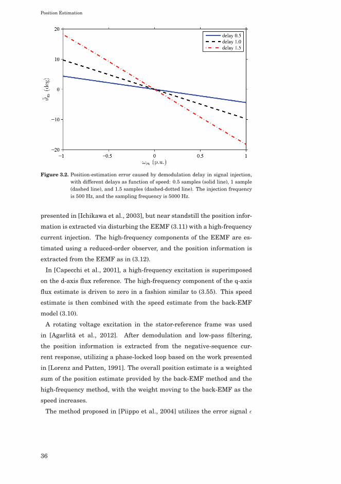
The effect of the demodulation error is illustrated in Figure 3.2 for de-
modulation delays of 0.5, 1 and 1.5 samples. The motor parameters are
Ld = 2.0 p.u. and Lq = 0.3 p.u. The injection frequency is ωc = 2π · 500rad/s and the sampling frequency is 5000 Hz. It can be seen that in this
case the position-estimation error at the rated speed with system delay of
1.5 samples is nearly 20 degrees.
3.4 Combined Observers
The signal-injection methods can provide reliable position estimate at
all speeds from standstill to rated speed. However, the injected high-
frequency excitation inflicts the system with additional noise and losses,
and they limit the maximum usable voltage. Therefore, several authors
have used combined observer, which rely on signal-injection methods only
at low speeds. As the speed increases, the amplitude of the injected
high-frequency excitation decreases and the underlying back-EMF-based
method begins to dominate the position estimation. Finally, the high-
frequency excitation is removed when the speed is above the desired tran-
sition speed, and the system relies only on the information provided by
the back-EMF-based method.
The information provided by the signal injection can be utilized in var-
ious ways. In [Ha et al., 1999], a high-frequency current excitation was
injected in the estimated d-axis direction. The position information is
extracted from the induced high-frequency voltage responses with multi-
plication and low-pass filtering
ε = LPF {ucducq} ≈ Ld − Lq
2Ldω
2c i
2c ϑm. (3.54)
This error signal is driven to zero with the PI-mechanism
ωm = kpε+
∫kiεdt, (3.55)
from which the position information is obtained according to (3.21). The
overall position estimate is a weighted sum of this and the position esti-
mate obtained from (3.5), with weight on the signal-injection method at
low speeds.
The high-frequency current excitation was also used in [Kato et al.,
2011]. At high speeds, the position estimation is based on the method
35
Position Estimation
Figure 3.2. Position-estimation error caused by demodulation delay in signal injection,with different delays as function of speed: 0.5 samples (solid line), 1 sample(dashed line), and 1.5 samples (dashed-dotted line). The injection frequencyis 500 Hz, and the sampling frequency is 5000 Hz.
presented in [Ichikawa et al., 2003], but near standstill the position infor-
mation is extracted via disturbing the EEMF (3.11) with a high-frequency
current injection. The high-frequency components of the EEMF are es-
timated using a reduced-order observer, and the position information is
extracted from the EEMF as in (3.12).
In [Capecchi et al., 2001], a high-frequency excitation is superimposed
on the d-axis flux reference. The high-frequency component of the q-axis
flux estimate is driven to zero in a fashion similar to (3.55). This speed
estimate is then combined with the speed estimate from the back-EMF
model (3.10).
A rotating voltage excitation in the stator-reference frame was used
in [Agarlita et al., 2012]. After demodulation and low-pass filtering,
the position information is extracted from the negative-sequence cur-
rent response, utilizing a phase-locked loop based on the work presented
in [Lorenz and Patten, 1991]. The overall position estimate is a weighted
sum of the position estimate provided by the back-EMF method and the
high-frequency method, with the weight moving to the back-EMF as the
speed increases.
The method proposed in [Piippo et al., 2004] utilizes the error signal ε
36
Position Estimation
(3.46) directly in both the speed and position estimation,
ωm =eq
ψpm
+ γi
∫εdt (3.56a)
ϑm =
∫(ωm + γpε) dt, (3.56b)
where γp and γi are adaptation gains, eq is the q-axis component of the
back-EMF and ψpm is the magnitude of the estimated permanent-magnet
flux. When the signal injection is not used, the speed estimation is based
on the pure voltage model.
In the combined observer proposed in [Piippo and Luomi, 2005] and
used in Publication VI, the error signal ε is driven to zero using the PI-
mechanism
ωε = γpε+ γi
∫εdt. (3.57)
The adaptation gains are
γp =αi
2kε, γi =
α2i
6kε, (3.58)
where αi is the approximate bandwidth of the PI mechanism, kε is the
signal-injection gain (3.50) and the bandwidth of the low-pass filter in
(3.46) or (3.48) is αlp = 3αi. The speed correction term ωε is then incorpo-
rated in the flux observer (3.35a) according to
dψs
dt= us − Rsis − (ωm + ωε)Jψs +Kis. (3.59)
The gain selection (3.58) was derived in [Piippo and Luomi, 2005], as-
suming fast flux-tracking loop and slow speed-tracking loop. If the situa-
tion is reversed, the gain selection has to be modified. Assuming accurate
model parameter estimates and the speed-adaptation law (3.35d) in the
steady state, i.e. iq = 0, the characteristic polynomial of the linearized
closed-loop system consisting of (2.2), (3.35c), (3.49), (3.57), and (3.59) is
s4 +A3s3 +A2s
2 +A1s+A0, (3.60a)
where
A3 = αlp − k11 + βk21 (3.60b)
A2 =2kε
Ld − LqαlpLdγp − αlp(k11 − βk21)
− ωm(k21 − ωm + βk11)
(3.60c)
A1 =2kε
Ld − Lqαlp [Ld(γi − γpk11) + Lqβγp(ωm − k21)]
− αlpωm(k21 − ωm + βk11)
(3.60d)
A0 =2kε
Ld − Lqαlpγi(Lqβ(ωm − k21)− Ldk11) (3.60e)
37
Position Estimation
and αlp is the bandwidth of the low-pass filter in (3.48).
For design purposes, the characteristic polynomial is written as
(s2 + bs+ c)(s+ α′lp)(s+ αε), (3.61)
where b and c are design parameters associated with the flux observer,
and α′lp and αε are design parameters associated with the low-pass filter
(3.48) and the speed-correction loop (3.57), respectively. Equating (3.60)
and (3.61), the gains of the augmented observer can be written as func-
tions of the design parameters {b, c, α′lp, αε}, which all should be positive
in order to stabilize the system. Other design parameter sets could be
chosen as well.
When b, c, α′lp, and αε are the design parameters, the observer gain k11
is determined by
k11 = βk21 − b− αε + αlp − α′lp (3.62a)
and the PI gains γi and γp are
γi =Ld − Lq
2kε
α′lpαεc
αlp [Lqβ(ωm − k21)− Ldk11](3.62b)
γp =Ld − Lq
2kε
ωm(k21 − ωm + βk11)
Lqβ(ωm − k21)− Ldk11
+Ld − Lq
2kε
α′lp(c+ bαε) + cαε
αlp [Lqβ(ωm − k21)− Ldk11]
− LdγiLqβ(ωm − k21)− Ldk11
.
(3.62c)
The remaining constraint from (3.60) and (3.61) is a cubic equation for
α′lp. However, if sufficiently large bandwidth is selected for the low-pass
filter, then α′lp = αlp can be approximated, as is done in Publication VII.
Since the parameter uncertainties are compensated for by ωε in (3.59),
the behaviour of ωε at low speeds should be considered. It can be shown
from (2.2), (3.35c) and (3.59) that when ωm = 0, the steady-state solution
for ωε is obtained from
βLqω2ε − (Rs + Ldk1 + Lqβk2)ωε + Rs(k2 − βk1) = 0. (3.63)
Depending on the parameter estimates and gain selection, real valued
(stabilizing) solutions for (3.63) might not exist. Moreover, in [Piippo and
Luomi, 2005] it was suggested that ωε should be limited between some
small values −ωε,lim and ωε,lim. Even if the solutions for (3.63) are real
valued, it is not easy to assure that both solutions are small, and ωε might
reach the limit with no practical contribution to the position correction.
Hence, the combined observer (3.59) might easily become unstable when
38

Position Estimation
applied for synchronous reluctance motor drives if the gain selection is
not carefully inspected with even small parameter uncertainties. Due to
these problems, an alternative method to utilize the error signal ε was
proposed in Publication VII.
39

Position Estimation
40
4. Parameter Adaptation
The accuracy and stability of the back-EMF-based methods considered
in this thesis depend on the parameters of the equivalent-circuit model.
However, only a few works have addressed practical approaches to obtain
the model parameters without preliminary measurements for position-
sensorless synchronous reluctance motor drives.
Methods based on recursive system parameter identification were used
in [Ghaderi et al., 2006] and [Ichikawa et al., 2006], where [Ghaderi et al.,
2006] utilizes block-pulse function excitation and [Ichikawa et al., 2006]
utilizes M-sequence excitation. A simple method to estimate the average
inductance was proposed in [Paulus et al., 2011]. The method was in-
tended to be used with the observer proposed in [Stumper et al., 2010].
However, it was assumed in the derivation that id = iq, which is not al-
ways the case.
In order to avoid preliminary measurements requiring additional hard-
ware, methods to estimate the motor model parameters during normal
operation of the drive were proposed in Publication II and Publication
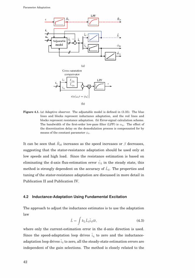
VII. The overall observer structure is illustrated in Figure 4.1.
4.1 Stator-Resistance Adaptation Using Fundamental Excitation
For improved low-speed operation, the reduced-order observer (3.27) can
be augmented with the stator-resistance adaptation law
Rs =
∫kRLdiddt. (4.1)
Since in this method the d-axis current-estimation error is driven to zero,
the steady-state estimation errors are independent of the gain selections.
The steady-state resistance-estimation error derived in Publication IV is
Rs0 = ωm(Ld − Lq)cos(2ϑm0)− β sin(2ϑm0)− 1
2β− ωm
βLd. (4.2)
Parameter Adaptation
(a)
(b)
Figure 4.1. (a) Adaptive observer. The adjustable model is defined in (3.35). The bluelines and blocks represent inductance adaptation, and the red lines andblocks represent resistance adaptation. (b) Error-signal calculation scheme.The bandwidth of the first-order low-pass filter (LPF) is αlp. The effect ofthe discretization delay on the demodulation process is compensated for bymeans of the constant parameter φd.
It can be seen that Rs0 increases as the speed increases or β decreases,
suggesting that the stator-resistance adaptation should be used only at
low speeds and high load. Since the resistance estimation is based on
eliminating the d-axis flux-estimation error ψd in the steady state, this
method is strongly dependent on the accuracy of Ld. The properties and
tuning of the stator-resistance adaptation are discussed in more detail in
Publication II and Publication IV.
4.2 Inductance-Adaptation Using Fundamental Excitation
The approach to adjust the inductance estimates is to use the adaptation
law
L =
∫kLLdiddt, (4.3)
where only the current-estimation error in the d-axis direction is used.
Since the speed-adaptation loop drives iq to zero and the inductance-
adaptation loop drives id to zero, all the steady-state estimation errors are
independent of the gain selections. The method is closely related to the
42
Parameter Adaptation
permanent-magnet flux adaptation law proposed in [Piippo et al., 2009].
The same adaptation law (4.3) can be used for both the d-axis induc-
tance and the q-axis inductance. The resulting steady-state inductance
estimates, derived in Publication VI, are
Ld =Ld + Lq
2− βRs
ωm+
Ld − Lq
2cos(2ϑm0)− β
Ld − Lq
2sin(2ϑm0) (4.4a)
Lq =Ld + Lq
2+
Rs
βωm− Ld − Lq
2cos(2ϑm0)− Ld − Lq
2βsin(2ϑm0). (4.4b)
Both inductance estimates are inversely proportional to the speed, which
suggests that the inductances should be adapted only at high speeds. On
the other hand, Ld is proportional to β and Lq is inversely proportional to
β, which suggests that Ld should be adapted at low loads and Lq should
be adapted at high loads. The properties and tuning of the inductance
adaptation are discussed in more detail in Publication VII.
4.3 Stator-Resistance Adaptation Using High-Frequency SignalInjection
The stator-resistance adaptation mechanism proposed in [Piippo et al.,
2009] utilized an integrator to drive the speed-correction term ωε (3.57)
to zero. The overall combined observer with the signal injection and the
resistance adaptation is of the seventh order.
The method proposed in Publication VII is to combine the information
provided by the signal injection with the flux observer via updating the
stator-resistance estimate directly without intermediate states,
Rs = γpε+
∫γiεdt. (4.5)
The additional integrator can be removed, and the order of the overall
system is reduced by one.
Since the signal injection does not affect the steady-state error equation,
Rs can be solved from (3.29) as function of the position-estimation error,
inductance errors and observer gains,
Rs =ωmLd − Lq
2
k11 − βk21 + βωm
ωm − k21 + βk11
[1− cos(2ϑm0)
]+ ωm
Ld − Lq
2
k21 − ωm + βk11k21 − ωm − βk11
sin(2ϑm0)
+ ωmLdk11 + Lqβ(k21 − ωm)
k21 − ωm − βk11,
(4.6)
where k1 and k2 have been replaced with k11 and k21, respectively. It
can be seen that at standstill the estimation error is zero regardless of
43

Parameter Adaptation
the position-estimation error. In no-load condition, if ϑm0 = 0 is obtained,
the resistance-estimation error increases proportionally to ωmLdk11/(k21−ωm). This behaviour should be considered in more detail, if accurate re-
sistance estimate is desired at low speeds. The properties and tuning of
the resistance adaptation are discussed in more detail in Publication VII.
44

5. Summaries of Publications
5.1 Abstracts
Publication I
This paper deals with reduced-order observers with stator-resistance
adaptation for motion-sensorless permanent-magnet synchronous motor
drives. An analytical solution for the stabilizing observer gain and sta-
bility conditions for the stator-resistance adaptation are derived. The
proposed observer design is experimentally tested using a 2.2-kW motor
drive; stable operation at very low speeds under different loading condi-
tions is demonstrated.
Publication II
A reduced-order position observer with stator-resistance adaptation is ap-
plied for motion-sensorless synchronous reluctance motor drives. A gen-
eral analytical solution for the stabilizing observer gain and stability con-
ditions for the stator-resistance adaptation are given. The local stability
of the position and stator-resistance estimation is guaranteed at every
operating point except the zero frequency, if inductances are known ac-
curately. The observer design is experimentally tested using a 6.7-kW
synchronous reluctance motor drive; stable operation at low speeds under
various loading conditions is demonstrated.
Publication III
This paper deals with the modeling of the magnetic saturation in syn-
chronous reluctance motors (SyRMs). The saturation is modeled by
Summaries of Publications
means of analytical expressions, which can be easily embedded in dy-
namic equivalent-circuit models. A modified power function - proposed in
this paper - can take into account the cross saturation between the orthog-
onal windings, it is physically consistent, and the number of its parame-
ters is small. The function can be used in real-time control applications
and in computer simulations. The model fits well to the experimentally
measured inductances of a 6.7-kW SyRM. As an application example, the
proposed saturation model was implemented in a full-order observer of a
motion-sensorless drive, and experimental results are shown.
Publication IV
A back-electromotive-force-based reduced-order position observer with
stator-resistance adaptation is analyzed for motion-sensorless syn-
chronous reluctance motor (SyRM) drives. Analytical equations for
steady-state estimation errors and stability conditions are derived (with
and without resistance adaptation), taking into account errors in the pa-
rameter estimates. The effect of the observer gain on the noise reduction
is studied by means of eigenvector analysis. A robust gain selection is
proposed, which maximizes the allowed uncertainties in the parameter
estimates. The proposed observer design is experimentally evaluated us-
ing a 6.7-kW SyRM drive; stable operation is demonstrated at low speeds
under various parameter errors.
Publication V
Two back-electromotive-force-based position observers are compared for
motion-sensorless synchronous motor drives: the reduced-order observer
and the adaptive full-order observer. A stabilizing gain is proposed for
the adaptive full-order observer, which guarantees the local stability of
the closed-loop system, if the motor parameters are known. Equations
for the steady-state position error and for the linearized estimation-error
dynamics under erroneous parameters are derived, and the robustness
of the two observers against parameter errors is analyzed and compared.
The observers are experimentally evaluated using a 6.7-kW synchronous
reluctance motor drive in low-speed operation and under parameter er-
rors. The gain selection of the reduced-order observer is easier, but the
adaptive full-order observer can be made more robust against parameter
variations and noise.
46
Summaries of Publications
Publication VI
A back-EMF-based position observer for motion-sensorless synchronous
reluctance motor drives is augmented with high-frequency signal-
injection method for improved lowspeed operation. Previously proposed
observer structure is further improved to account for the cross saturation
in the motor. The combined observer is experimentally evaluated using a
6.7- kW synchronous reluctance motor drive in low-speed operation and
under various load conditions. The resulting position error at low speeds
and standstill is small.
Publication VII
A back-EMF-based position observer for motion-sensorless synchronous
reluctance motor (SyRM) drives is augmented with parameter-adaptation
laws for improved operation at all speeds, including standstill. The aug-
mented observer is theoretically analyzed under various operation condi-
tions. The analysis indicates that the stator-resistance adaptation should
be enabled only at low speeds, the d-axis inductance adaptation should
be enabled only at medium and high speeds near no load, and the q-axis
inductance adaptation should be enabled only at high speeds under high
load. The augmented observer is experimentally evaluated using a 6.7-
kW SyRM drive.
5.2 Contribution of the Thesis
The main contributions of the thesis can be summarized as follows:
• Saturation models for synchronous reluctance motors were compared,
and a physically reasonable saturation model for synchronous reluc-
tance motors was proposed. (Publication III)
• Steady-state position-estimation error and stability of a simple first-
order observer were analyzed under erroneous model parameters. (Pub-
lication I, Chapter 3)
• Steady-state estimation errors and stability of a reduced-order observer
were analyzed under erroneous model parameters. Based on the anal-
47
Summaries of Publications
ysis, robust gain selection was proposed with maximal tolerance for
model parameter uncertainties. (Publication IV)
• The reduced-order observer was augmented with resistance-adaptation
mechanism for improved low-speed operation. The steady-state esti-
mation error and stability of the resistance adaptation were analyzed
under erroneous model parameters. Based on the analysis, stabilizing
gain selection for the augmented observer was proposed. (Publication
II, Publication IV)
• Steady-state estimation errors and stability of a speed-adaptive full-
order observer were analyzed under erroneous parameter estimates.
Based on the analysis, stabilizing gain selection was proposed. (Pub-
lication V)
• Parameter sensitivity and estimation performance of the reduced-order
observer and the speed-adaptive full-order observer were compared.
(Publication V)
• Compensation mechanism for the position-estimation error caused by
cross-saturation in signal-injection assisted full-order observer was pro-
posed. (Publication VI)
• Stabilizing gain selection for the speed-adaptive full-order observer
with speed correction from signal injection was proposed. (Publication
VI, Chapter 3)
• Inductance-adaptation law using the back-electromotive force was pro-
posed for the speed-adaptive full-order observer. Steady-state estima-
tion errors and stability of the inductance adaptation were analyzed
with erroneous model parameters. Based on the analysis, stabilizing
gain selection was proposed. (Publication VII)
• Resistance-adaptation law using high-frequency signal injection was
proposed for the speed-adaptive full-order observer. Steady-state esti-
mation errors and stability of the resistance adaptation were analyzed
with erroneous model parameters. Based on the analysis, stabilizing
gain selection was proposed. (Publication VII)
48
6. Conclusions
Modern synchronous reluctance motors have emerged as feasible competi-
tors to induction motors in variable-speed drives, due to simpler structure
and smaller energy losses. In order to operate synchronous reluctance
motors, information on the rotor position is needed. In low-cost drives,
position-sensorless control methods are often preferred, since the mechan-
ical position encoders are expensive. Moreover, the mechanical encoders
are prone to failures, and cannot be installed in certain conditions.
In this thesis, model-based position-estimation methods have been stud-
ied for synchronous reluctance motor drives. Since the accuracy of the po-
sition estimation depends on the accuracy of the equivalent-circuit model
parameters, effects of uncertainties in these model parameters have been
analyzed.
The back-electromotive force induced by the rotational movement of the
rotor can provide satisfactory position information in order to obtain sta-
ble operation at speeds above approximately 5–10% of the rated speed.
At lower speeds, modeling errors and measurement noise impair perfor-
mance, leading possibly to instabilities.
Additional information on the rotor position can be obtained if the drive
is excited with additional test signals. The purpose of these test signals is
to map the spatial structure of the motor. However, the test signals inflict
the system with acoustic noise and increase losses. Furthermore, since
the test signals are usually generated by the same frequency converter
which supplies the motor with the back-electromotive force, the voltage
available for the back-electromotive force is limited when additional test
signals are used. Therefore, additional test signals should be used only at
the lowest speeds.
Two slightly different ways of combining the information provided
by the signal injection with the underlying model based on the back-
Conclusions
electromotive force were considered in Publication VI and Publication VII.
The approach used in Publication VI introduces an additional state to the
system. This state is then bound in order to limit the corrective effects
of the signal injection and in order to decouple the signal injection from
the underlying model at high speeds. However, it is not straightforward
to determine how the limits should be set. The approach proposed in
Publication VII utilizes the information provided by the signal injection
directly to update the resistance estimate, but on the other hand, this ap-
proach leads to an erroneous resistance estimate as the speed increases,
which might impair the performance of the drive in transient states at
low speeds.
If the equivalent-circuit model parameters are known in advance with
moderate accuracy, the observer gains can be determined following the de-
sign guidelines given in Publication IV and Publication V. If the parame-
ters are unknown, or the accuracy is not satisfactory, the parameter adap-
tation methods proposed in Publication VII can be used. Accurate param-
eter estimates can be achieved if the results on the estimation accuracy
at different operating points are considered. The inductance-adaptation
mechanism can be used in an initialization test to obtain the inductances
at desired operating points or to obtain saturation-model parameters.
Although several approaches can be used in combining the informa-
tion provided by the signal injection with the information from the back-
electromotive force, no thorough comparison on the benefits and draw-
backs of these approaches yet exists. Further, the cross-coupling between
the d- and q-axis distorts the position information seen by the signal in-
jection, if the coupling is not compensated for. The compensation method
proposed in Publication VI utilized a compensation factor, which was ob-
tained via measuring the incremental inductances with the actual rotor
position available. A mechanism to identify the compensation factor with-
out position sensor is still needed.
50
Bibliography
[Agarlita et al., 2012] Agarlita, S.-C., Boldea, I., and Blaabjerg, F. (2012). High-frequency-injection-assisted “active flux”-based sensorless vector control of re-luctance synchronous motors, with experiments from zero speed. IEEE Trans.Ind. Appl., 48(6):1931–1939.
[Arefeen et al., 1994] Arefeen, M. S., Ehsani, M., and Lipo, T. A. (1994). Sen-sorless position measurement in synchronous reluctance motor. IEEE Trans.Power Electron., 9(6):624–630.
[Boglietti and Pastorelli, 2008] Boglietti, A. and Pastorelli, M. (2008). Inductionand synchronous reluctance motors comparison. In Proc. IEEE IECON’08,pages 2041–2044, Orlando, FL.
[Capecchi et al., 2001] Capecchi, E., Guglielmo, P., Pastorelli, M., and Vagati, A.(2001). Position-sensorless control of the transverse-laminated synchronousreluctance motor. IEEE Trans. Ind. Appl., 37(6):1768–1776.
[Chen et al., 2004] Chen, C.-G., Liu, T.-H., Lin, M.-T., and Tai, C.-A. (2004). Posi-tion control of a sensorless synchronous reluctance motor drive. IEEE Trans.Ind. Electron., 51(1):15–25.
[Choi and Sul, 1996] Choi, J. and Sul, S. (1996). Inverter output voltage syn-thesis using novel dead time compensation. IEEE Trans. Power Electron.,11(2):221–227.
[Consoli et al., 1999] Consoli, A., Russo, F., Scarcella, G., and Testa, A. (1999).Low- and zero-speed sensorless control of synchronous reluctance motors.IEEE Trans. Ind. Appl., 35(5):1050–1057.
[Consoli et al., 2007] Consoli, A., Scarcella, G., Scelba, G., Testa, A., and Tri-olo, D. A. (2007). Sensorless rotor position estimation in synchronous reluc-tance motors exploiting a flux deviation approach. IEEE Trans. Ind. Appl.,43(5):1266–1273.
[Corzine et al., 1998] Corzine, K. A., Kuhn, B. T., Sudhoff, S. D., and Hegner,H. J. (1998). An improved method for incorporating magnetic saturation in theq-d synchronous machine model. IEEE Trans. Energy Convers., 13(3):270–275.
[Cruickshank et al., 1971] Cruickshank, A. J. O., Anderson, A. F., and Menzies,R. W. (1971). Theory and performance of reluctance motors with axially lami-nated anisotropic rotors. Proc. IEE, 118(7):887–894.
51
Bibliography
[de Kock et al., 2007] de Kock, H. W., Kamper, M. J., Ferreira, O. C., and Ken-nel, R. M. (2007). Position sensorless control of the reluctance synchronousmachine considering high frequency inductances. In Proc. PEDS 2007, pages812–821, Bangkok, Thailand.
[Degner and Lorenz, 1998] Degner, M. W. and Lorenz, R. D. (1998). Using multi-ple saliencies for the estimation of flux, position, and velocity in AC machines.IEEE Trans. Ind. Appl., 34(5):1097–1104.
[Ghaderi and Hanamoto, 2011] Ghaderi, A. and Hanamoto, T. (2011). Wide-speed-range sensorless vector control of synchronous reluctance motors basedon extended programmable cascaded low-pass filters. IEEE Trans. Ind. Elec-tron., 58(6):2322–2333.
[Ghaderi et al., 2006] Ghaderi, A., Hanamoto, T., and Teruo, T. (2006). A novelimplementation of low speed sensorless vector control of synchronous reluc-tance motors with a new online parameter identification approach. In Proc.IEEE APEC’06, pages 211–217, Dallas, TX.
[Guglielmi et al., 2006] Guglielmi, P., Pastorelli, M., and Vagati, A. (2006). Im-pact of cross-saturation in sensorless control of transverse-laminated syn-chronous reluctance motors. IEEE Trans. Ind. Electron., 53(2):429–439.
[Ha et al., 1999] Ha, J.-I., Kang, S.-J., and Sul, S.-K. (1999). Position-controlledsynchronous reluctance motor without rotational transducer. IEEE Trans.Ind. Appl., 35(6):1393–1398.
[Harnefors and Nee, 2000] Harnefors, L. and Nee, H.-P. (2000). A general al-gorithm for speed and position estimation of AC motors. IEEE Trans. Ind.Electron., 47(1):77–83.
[Ichikawa et al., 2003] Ichikawa, S., Tomita, M., Doki, S., and Okuma, S. (2003).Sensorless control of synchronous reluctance motors based on an extendedEMF model and initial position estimation. In Proc. IEEE IECON’03, vol-ume 3, pages 2150–2155, Roanoke, VA.
[Ichikawa et al., 2006] Ichikawa, S., Tomita, M., Doki, S., and Okuma, S. (2006).Sensorless control of synchronous reluctance motors based on extended EMFmodels considering magnetic saturation with online parameter identification.IEEE Trans. Ind. Appl., 42(5):1264–1274.
[Inoue et al., 2010] Inoue, Y., Morimoto, S., and Sanada, M. (2010). A novel con-trol scheme for wide speed range operation of direct torque controlled syn-chronous reluctance motor. In Proc. IEEE ECCE’10, volume 1, pages 192–198,Atlanta, GA.
[Jansen and Lorenz, 1995] Jansen, P. L. and Lorenz, R. D. (1995). Transducer-less position and velocity estimation in induction and salient AC machines.IEEE Trans. Ind. Appl., 31(2):240–247.
[Jovanovic et al., 1998] Jovanovic, M. G., Betz, R. E., and Platt, D. (1998). Sen-sorless vector controller for a synchronous reluctance motor. IEEE Trans. Ind.Appl., 34(2):346–354.
[Kang et al., 1999] Kang, S.-J., Kim, J.-M., and Sul, S.-K. (1999). Position sen-sorless control of synchronous reluctance motor using high frequency currentinjection. IEEE Trans. Energy Convers., 14(4):1271–1275.
52
Bibliography
[Kato et al., 2011] Kato, K., Tomita, M., Hasegawa, M., Doki, S., Okuma, S.,and Kato, S. (2011). Position and velocity sensorless control of synchronousreluctance motor at low speed using disturbance observer for high-frequencyextended EMF. In Proc. IEEE IECON’11, volume 1, pages 1971–1976, Mel-bourne, VIC.
[Kostko, 1923] Kostko, J. K. (1923). Polyphase reaction synchronous motors.Journal of AIEE, 42(11):1162–1168.
[Kreindler et al., 1993] Kreindler, L., Testa, A., and Lipo, T. (1993). Positionsensorless synchronous reluctance motor drive using the stator phase voltagethird harmonic. In Conf. Rec. IEEE-IAS Annu. Meeting, volume 1, pages 679–686, Toronto, ON.
[Lagerquist et al., 1994] Lagerquist, R., Boldea, I., and Miller, J. (1994). Sen-sorless control of the synchronous reluctance motor. IEEE Trans. Ind. Appl.,30(3):673–682.
[Landsmann et al., 2010a] Landsmann, P., D.Paulus, Stolze, P., and Kennel, R.(2010a). Saliency based encoderless predictive torque control without sig-nal injection for a reluctance synchronous machine. In Proc. EPE-PEMC’10,Ohrid, Macedonia.
[Landsmann et al., 2010b] Landsmann, P., Kennel, R., de Kock, H., and Kamper,M. (2010b). Fundamental saliency based encoderless control for reluctancesynchronous machines. In Proc. ICEM’10, Rome, Italy.
[Lipo and Krause, 1967] Lipo, T. A. and Krause, P. C. (1967). Stability analysisof a reluctance-synchronous machine. IEEE Trans. Power App. Syst., PAS-86(7):825–834.
[Lorenz, 2001] Lorenz, R. D. (2001). Practical issues and research opportuni-ties when implementing zero speed sensorless control. In Proc. ICEMS’01,volume 1, Shenyang, China.
[Lorenz and Patten, 1991] Lorenz, R. D. and Patten, K. W. V. (1991). High-resolution velocity estimation for all-digital, AC servo drives. IEEE Trans.Ind. Appl., 27(4):701–705.
[Matsuo and Lipo, 1995] Matsuo, T. and Lipo, T. A. (1995). Rotor position de-tection scheme for synchronous reluctance motor based on current measure-ments. IEEE Trans. Ind. Appl., 31(4):860–868.
[Morales-Caporal and Pacas, 2008] Morales-Caporal, R. and Pacas, M. (2008).Encoderless predictive direct torque control for synchronous reluctance ma-chines at very low and zero speed. IEEE Trans. Ind. Electron., 55(12):4408–4416.
[Paulus et al., 2011] Paulus, D., Stumper, J.-F., Landsmann, P., and Kennel, R.(2011). Encoderless field-oriented control of a synchronous reluctance machinewith position and inductance estimators. In ICPE 2011-ECCE Asia, pages1153–1160, Jeju, Korea.
[Pedersen et al., 1993] Pedersen, J. K., Blaabjerg, F., Jensen, J. W., andThogersen, P. (1993). An ideal PWM-VSI inverter with feedforward and feed-back compensation. In Proc. EPE’93, volume 4, pages 312–318, Brighton, U.K.
53
Bibliography
[Piippo et al., 2004] Piippo, A., Hinkkanen, M., and Luomi, J. (2004). Sensorlesscontrol of PMSM drives using a combination of voltage model and HF signalinjection. In Conf. Rec. IEEE-IAS Annu. Meeting, volume 2, pages 964–970,Seattle, WA.
[Piippo et al., 2009] Piippo, A., Hinkkanen, M., and Luomi, J. (2009). Adaptationof motor parameters in sensorless PMSM drives. IEEE Trans. Ind. Appl.,45(1):203–212.
[Piippo and Luomi, 2005] Piippo, A. and Luomi, J. (2005). Adaptive observercombined with HF signal injection for sensorless control of PMSM drives. InProc. IEEE IEMDC’05, pages 674–681, San Antonio, TX.
[Raca et al., 2008] Raca, D., García, P., Reigosa, D., Briz, F., and Lorenz, R.(2008). A comparative analysis of pulsating vs. rotating vector carrier signalinjection-based sensorless control. In Proc. IEEE APEC’08, pages 879–885,Austin, TX.
[Schroedl and Weinmeier, 1994] Schroedl, M. and Weinmeier, P. (1994). Sensor-less control of reluctance machines at arbitrary operating conditions includingstandstill. IEEE Trans. Power Electron., 9(2):225–231.
[Stumper et al., 2010] Stumper, J.-F., Paulus, D., Landsmann, P., and Kennel,R. (2010). Encoderless field-oriented control of a synchronous reluctance ma-chine with a direct estimator. In First Symposium on Sensorless Control forElectrical Drives (SLED), 2010, pages 18–23, Padova, Italy.
[Tomita et al., 1998] Tomita, M., Senjyu, T., Doki, S., and Okuma, S. (1998). Newsensorless control for brushless DC motors using disturbance observers andadaptive velocity estimations. IEEE Trans. Ind. Electron., 45(2):274–282.
[Vagati et al., 1997] Vagati, A., Pastorelli, M., and Franceschini, G. (1997). High-performance control of synchronous reluctance motors. IEEE Trans. Ind.Appl., 33(4):983–991.
[Villet et al., 2012] Villet, W. T., Kamper, M. J., Landsmann, P., and Kennel, R.(2012). Evaluation of a simplified high frequency injection position sensor-less control method for reluctance synchronous machine drives. In Proc. IETPEMD 2012, volume 1, Bristol, UK.
[Wei and Liu, 2012] Wei, M.-Y. and Liu, T.-H. (2012). A high-performance sen-sorless position control system of a synchronous reluctance motor using dualcurrent-slope estimating technique. IEEE Trans. Ind. Electron., 59(9):3411–3426.
[Xiang and Nasar, 1995] Xiang, Y. Q. and Nasar, S. A. (1995). Estimation of rotorposition and speed of a synchronous reluctance motor for servodrives. IEEProc. Electr. Power Appl., 142(3):201–205.
54

Errata
55

9HSTFMG*afhcgc+
ISBN 978-952-60-5726-2 ISBN 978-952-60-5727-9 (pdf) ISSN-L 1799-4934 ISSN 1799-4934 ISSN 1799-4942 (pdf) Aalto University School of Electrical Engineering Department of Electrical Engineering and Automation www.aalto.fi
BUSINESS + ECONOMY ART + DESIGN + ARCHITECTURE SCIENCE + TECHNOLOGY CROSSOVER DOCTORAL DISSERTATIONS
Aalto-D
D 8
6/2
014
Modern synchronous reluctance motors are becoming viable competitors for induction motors in variable-speed drives due to smaller energy losses and simpler structure. In order to operate synchronous motors, information on the rotor position is needed. Position-acquicition methods which do not rely on mechanical sensors are often preferred, since mechanical sensors are expensive and prone to failures. In this thesis, three model-based position-estimation methods are analyzed and experimentally evaluated for synchronous reluctance motors. Since accuracy of the considered estimation methods depends on the equivalent-model parameters, further effort has been put on parameter-estimation methods which can be implemented during normal operation of the drive.
Toni T
uovinen M
odel-Based P
osition Estim
ation for Synchronous Reluctance M
otor Drives
Aalto
Unive
rsity
Department of Electrical Engineering and Automation
Model-Based Position Estimation for Synchronous Reluctance Motor Drives
Toni Tuovinen
DOCTORAL DISSERTATIONS