Embed Size (px)
Citation preview

Disclosure to Promote the Right To Information
Whereas the Parliament of India has set out to provide a practical regime of right to information for citizens to secure access to information under the control of public authorities, in order to promote transparency and accountability in the working of every public authority, and whereas the attached publication of the Bureau of Indian Standards is of particular interest to the public, particularly disadvantaged communities and those engaged in the pursuit of education and knowledge, the attached public safety standard is made available to promote the timely dissemination of this information in an accurate manner to the public.
इंटरनेट मानक
“!ान $ एक न' भारत का +नम-ण”Satyanarayan Gangaram Pitroda
“Invent a New India Using Knowledge”
“प0रा1 को छोड न' 5 तरफ”Jawaharlal Nehru
“Step Out From the Old to the New”
“जान1 का अ+धकार, जी1 का अ+धकार”Mazdoor Kisan Shakti Sangathan
“The Right to Information, The Right to Live”
“!ान एक ऐसा खजाना > जो कभी च0राया नहB जा सकता है”Bhartṛhari—Nītiśatakam
“Knowledge is such a treasure which cannot be stolen”
“Invent a New India Using Knowledge”
है”ह”ह
IS 8382 (1977): Pressure Regulators, Pre-set Used withMedical Gas Cylinders [MHD 13: Veterinary Hospital Planningand Surgical Instruments]

IS : 8382 - 1977
Indian Standard SPECIFICATION FOR
PRESSURE REGULATORS, PRE-SET USED WITH MEDICAL GAS CYLINDERS
Anaesthetic Resuscitation and Allied Equipment Sectional Committee, CPDC 13
Chairman Representing
BRIQ N. C. DASS Ministry of Defence ( DGAFMS ), New Delhi
Members
SHRI‘R. BANDYOPADHYAY Indian Oxygen Ltd, Calcutta SRRI J. A. MULIYIL ( Alternnte 1
SIIRI ~BALESHWAR SARAI BIIAR- ‘Khushwaqat Industries, Rewari GAVA
SHRI SATI~HWAR SARAI BHARGaVA ( &tern& )
SHRI D. K. BHARGAVA DR A. GHOSH
DR (SMT ) SHEELA THAKK.4R ( Allsmatc )
HONY SECRETARY DR S. PRA~IANIK DR V. RA JAGOPALAN
Industrial Medical Engineers, Delhi Railway Board, New Delhi
Indian Society of Anaesthetists, Patna Department of Health, Govt of West Bengal, Ca!cutta Health and Family Department, Govt of Tamil Nadu,
Madras SHRI J. R. SACHDEVA
1 Ministry of Defence ( DGI ), New Delhi
LT-COL R. K. DEY ( Alternate , DR R. S. SAXENA Directorate General of Health Services, New Delhi DR N. P. SINGH Depa:tment of Health, Govt of Goa, Daman & Diu,
Panaii SHRI R. SOUNDRIRARAJAN Directorate General ~of Technical Development,
New Delhi SHRI SOM PRAKASHA,
Director ( Consr Prods & Med Director General, IS1 ( Ex-ofjkio Member )
Instrs )
Secretary
SHRI D. K. AGRAWAL Deputy Director ( Consr Prods & Med Instrs ), IS1
( Continued on page 1
@ copyright r977 INDIAN STANDARDS INSTITUTION
This publication is protected under the Indian Copyright Acf ( XIV of 1957 ) and reproduction in whole or in part by a?y Feans except with written permission of the publisher shall be deemed to be an mfrlngement of copyright under the said Act.
IS:8382-1977
( Continued from page 1 )
Anaesthetic, Oxygen and Inhalation Therapy Equipment Subcommittee, CPDC 13 : 1
Convener
DR S. PRAMANIK
Representing
Department of Health, Govt of West Bengal, Calcutta
Members
SERI R. BANDYOPADRYAY SHRI J. A. MULIYIL ( Alternafe)
Indian Oxygen Ltd, Calcutta
SHRI BALESHWAR SAHAI BHAR- Khushwaqat Industries, Rewari OAVA
SHRI P. S. BHARQAVA ( Alternate ) SHRI S. P. BHARGAVA SRRI S. BISWAS
Industrial Medical Engineers, New Delhi Sur Electrical Co Pvt Ltd, Calcutta
SHXI T. S. GOENKA Asiatic Oxygen Ltd, Calcutta HONY SECRETARY Indian Society of Anaesthetists, Patna SHRI V. G. JAMPOTKAR SHRI JUC+AL K. PAUL
Messrs Jambotkar Enterprises, Bombay Breathing Equipment Co, New Delhi
SIII~I ALOE MAZUMDAR ( Alternate ) DR R. S. SAXENA Directorate General of Health Services, New Delhi BRIQ N. DASS DR S. S. VERMA
Ministry ofDefence ( DGAFMS ), New Delhi
DR A. GHOSA ( Alternate ) Railway Board, New Delhi
2
15:8382-E977
Indian Standard .
SPECIFICATION FOR PRESSURE RE-GULATORS, PRE-SET USED
WITH MEDICAL GAS CYLINDER-S
0. FOREWORD
0.1 This Indian Standard was adopted by the Indian Standards Institution on 15 February 1977, after the draft finalized by the Anaesthetic Resuscitation and Allied Equipment Sectional Committee had been approved by the Consumer Products and Medical Instruments Division Council.
0.2 Various types of medical gases are being used now-a-days during anaesthesia, analgesia, oxygen therapy, carbon dioxide shock therapy, artificial lung ventilation and in many other ralated fields. It has been a standard practice in this field to use pressure regulators pre-set types, to bring down the cylinder gas pressures to a lower value at which the actual apparatus works. It is, therefore, necessary that the pressure regulators should be compatible with the equipment to be used in con- junction with the regulators. This standard covers the requirements of such pressure regulators for controlling the pressure of gases from cylinders.
0.3 This standard keeps in view the manufacturing and trade practices followed in the country in this field. Assistance has also been derived from the following:
IS0 2563-1972 Welding-regulators for gas cylinder used in welding, cutting and related processes. International Organization for Standardization.
BS 3016 : 1972 Pressure regulators for use with butane/propane gases. British Standards Institution.
0.4 This standard contains clauses 6.2 and 10.1 which call for agreement between the purchaser -and the supplier and which permit the purchaser to use his option for selection to suit his requirements.
0.5 For the purpose of deciding whether a particular requirement of this standard is complied with, the final value, observed or calculated, ex- pressing the result of a test, shall be rounded off in accordance with IS : 2-1960*. The number of significant places retained in the rounded off value should be the same as that of the ‘specified value in this standard.
*Rules for rounding off numerical values ( revised ).
3
IS : 8382 - 1977
1. SCOPE
1.1 This standard covers the requirements for pressure regulators, pre- set type used with gas cylinders for anaesthesia, oxygen therapy and related applications for a nominal outlet pressure of 4.21 kgf/cm2, nor- mally used for compressed medical gases at pressures up to 200 kgf/cma ( 20 Pa* ) but does not apply to pipeline regulators.
2. TERMINOLOGY
2.1 For the purpose of this standard, a pressure regulator, pre-set type, shall mean a device for regulating a generally variable inlet pressure to as constant a pre-set outlet pressure as possible by setting a value suitably.
3. CLASSIFICATION
3.1 Pre-set type pressure regulators in this field shall be further classified on the basis of: (a) type of gases for which the regulator is designed, and (b) type of inlet connections provided for connection to cylinder valves.
4. UNIT OF PRESSURE
4.1 The pressures measured are gauge pressures and shall be expressed in kgf/cma (Pa).
5. MANUFACTURING REQUIREMENTS
5.1 Material
5.1.1 The material of regulator components liable to come into contact with the gases shall have adequate resistance to the chemical action of these gases under operating conditions.
5.1.2 Material subject to rusting shall not be used for parts in contact with oxygen.
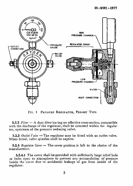
5.2 Design, Machining, Assembly and Finishing - See Fig. 1.
5.2.1 Oxygen Regulators - Regulator for oxygen shall be so designed, machined and assembled as to avoid internal burning; all components and accessories shall be thoroughly cleaned and degreased before assembly.
NOTE - Although this clause has been specially specified for oxygen regulators in the interest of safety, it may be dwrable to follow this provision for all gas regulators.
- *1 kgf/cms = 0.098 Pa = 0.098 N/mm’.
4
IS L 8382 - 1977
PRESSURE CHAMB
INLET CONNECTlO
FIG. 1 PRESSURE REGULATOR, PRE-SET TYPE
5.2.2 Filter - A dust filter having an effective cross-section, compatible with the discharge of the regulator, shall be mounted within the regula- tor, upstream of the pressure reducing valve.
5.2.3 Outlet Valve -The regulator may be fitted with an outlet valve. When fitted, valve spindles shall be captive.
5.2.4 Regulator Cover - The cover position is left to the choice of the manufacturer.
5.2.4.1 The cover shall be provided with sufficiently large relief hole or holes open to atmosphere to prevent any accumulation of pressure inside the cover due to accidental leakage of gas from inside of the regulator.
5
IS : 8382 - 1977
5.2.5 It shall open at not more than 160 N/cm2 ( 16 kgf/cm* approx) or not more than two-thirds of the minimum burst pressure of the diaphragm whichever is less. The relief valve shall be capable of relieving the regulator at a maximum burst pressure of the diaphragm at a supply pressure 50 percent greater than the maximum supply pressure of the corresponding gas.
NOTE - Whenever the outlets of a number of pre-set regulators are connected in parallel, only one relief valve with the same characteristics may be used, if so desired, in the line with the combined outlet.
5.2.6 Pressure Gauges - The pressure gauges for measurement of inlet pressure from the cylinders, if fitted to the regulators, shall conform to IS : 3624-1966” and shall be suitable for use with gases for which the regulators are designed to be used.
5.2.6.1 Pressure gauge shall be so fitted to the regulator that it does not interfere with the operation.
5.2.6.2 The regulator may be fitted with constant pressure indicator instead of a constant pressure gauge.
5.2.6.3 Pressure gauges shall be marked with the designation of the gas, that is, the oxygen pressure gauge shall be marked ‘OXYGEN’, the nitrous oxide pressure gauge shall be marked ‘NITROUS OXIDE’ and so on. Marking of pressure gauge with chemical symbols of gases shall not be permitted.
5.2.6.5 Oxygen pressure gauges shall also be marked ‘USE NO 011,’ or with a symbol, such as ‘CROSSED OIL CAN’.
6. CHARACTERISTICS OF CONNECTIONS
6.1 hlet Connection - All regulators shall be made in such a way that the inlet connection is compatible with the cylinder valve outlet designed for the gas contained.
6.2 Outlet Connection - The outlet of the regulator shall be suitable for detachable hose connection and nipple. The hose nipple shall have a cone angle of 45” and the hose nipple orientation shall be horizontal, awav from the cylinder. The threads on hose connection shall be in me&c system and till such tnne a standard is available, it may be as agreed to between the purchaser and the supplier.
*Specification for Bourdon tube pressure and vacuum gauges,
6
IS:8382 - 1977
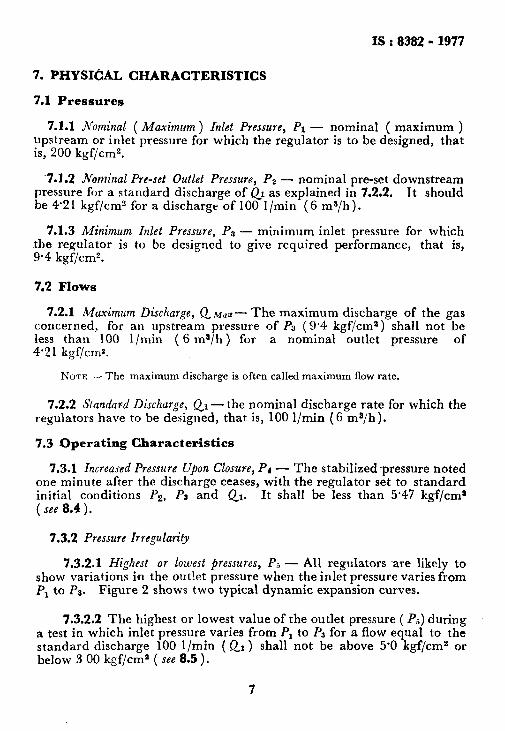
7. PHYSICAL CHARACTERISTICS
7.1 Pressures
7.1.1 Nominal ( Maximum ) I&t Pressure, PI - nornina ( maximum ) upstream or inlet pressure for which the regulator is to be designed, that is, 200 kgf/cm2.
7.1.2 Nominal Pre-set Outlet Pressure, Pe - nominal pre-set downstream pressure for a standard discharge of QI as explained in 7.2.2. It should be 4.21 kgf/cm2 for a discharge of 100 I/min (6 ms/h).
7.1.3 Minimum Inlet Pressure, PI - minimum inlet pressure for which the regulator is to be designed to give required performance, that is, 9.4 kgf/cm2.
7.2 Flows
7.2.1 Muximum Discharge, Q Mu*- The maximum discharge of the gas concerned, for an upstream pressure of PS (9.4 kgf/cm2) shall not be less than 100 l/min ( 6 ma/h) for a nominal outlet pressure of 4.2 1 kgf/cm*.
NOTE - The maximum discharge is often called maximum flow rate.
7.2.2 Sfandard Discharge, Ql- the nominal discharge rate for which the regulators have to be designed, that is, 100 l/min (6 ma/h).
7.3 Operating Characteristics
7.3.1 Increased Pressure Upon Closure, Pd - The stabilized ~pressure noted one minute after the discharge ceases, with the regulator set to standard initial conditions Pg, PS and Qr. It shall be less than 5.47 kgf/cml (see 8.4).
7.3.2 Pressure Irregularity
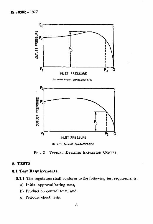
7.3.2.1 Highest or lowest pressures, PS - All regulators dare likely to show variations in the outlet pressure when the inlet pressure varies from PI to PB. Figure 2 shows two typical dynamic expansion curves.
7.3.2.2 The highest or lowest value of the outlet pressure ( Pa) during a test in which inlet pressure varies from P1 to Pa for a flow equal to the standard discharge 100 l/min ( Qr ) shall not be above 5.0 kgf/cma or below 3 00 kgf/cma ( see 8.5 ).
7
IS : 8382 - 1977
4
INLET PRESSURE
1A WITH IlLSiNG CMARACTERISTK:
t
Pl p3 INLET PRESSURE
28 WITH PALLING CtiARACTERlSTIC
FIG. 2 TYPICAL DYNAMIC EXPANSION CURVES
8. TESTS
8.1 Test Requirements
8.1.1 The regulators shall conform to the following test requirements:
a) Initial approval/rating tests,
b) Production control tests, and
c) Periodic check tests.
8
IS : 8382 - 1977
8.1.2 Initial approval/rating tests shall comprise the following:
a) Maximum discharge test ( see 8.4.1 ),
b) Test for pressure increase upon closure (see 8.5 ),
c) Test for pressure irregularity ( see 8.6 j,
d) Internal pressure test (see 8.8.1 ),
e) Leakage test (see 8.8.2), and
f I Ignition test (see 8.8.3 ).
8.1.2.1 The production control test to be performed on each com- pleted regulator shall comprise the following:
a) Leakage test (see 8.8.2 ), b) Test for pressure increase upon closure ( see 8.5), c) Maximum discharge test (see 8.4.1), and d) Relief valve test (see 5.2.5).
This test shall be conducted on 20 percent of the number of regula- tors assembled in a shift but not less than one per day,
8.1.3 Periodic check test comprising the following shall be conducted not less than once a year:
a) Maximum discharge test (see 8.4.1),
b) Leakage test (see 8.8.2),
c) Test for pressure increase upon closure ( see 8.5 ), and
d) Test for pressure irregularity ( see 8.6 ).
8.1.3.1 The ignition test shall be included as a periodic test if there is a change in the material or in the design of the regulator after its initial approval.
8.2 Type of Gas - Test should generally be made with oil free com- pressed air except that oxygen shall be used for the test given in 8.8.3. In all cases tests shall be made with dry gas, maximum 1000 ppm of moisture corresponding to a dew point of about -20°C. The results thus obtained shall be adjusted for the gas for which the regulator is designed, assuming the convention that the discharges are inversely proportional to the square roots of the densities.
8.3 Discharge and Pressure Measurements - The results of mea- surements shall be related to conditions of normal temperature and pressure ( 27 =t 2°C and 1 kgf/cm” ).
8.4 Rating Tests
8.4.1 Maximum Discharge ( QMU ) -The discharge QMa2: shall be found by discharging to atmosphere, Mith an upstream pressure of 9.4 kgf/cm? ( PB ). It should be in accordance with 7.2.1.
9
IS:8382-1977
8.4.2 Expansion Curve with Rising or Falling Characteristics
8.4.2.1 Characteristics plotted during continuous discharge - The curve ( see 7.3.2 and Fig. 2 ) gives the downstream pressure as a function of the upstream pressure. It shall be plotted during a test starting with initial values of PI, P2 and Qt. The test shall last at least 15 min and continue unttl the upstream pressure is not greater than Ps.
8.5 Test for Pressure Increase Upon Closure - The testing device used at the outlet side should contain a low pressure indication device to record the pressure rise at the regulator outlet.
8.5.1 With the regulator set to same conditions for standard discharge, the outlet should be blocked. The outlet pressure will go up and stabilize. The reading for PP should be taken one minute after full closure on the low pressure side. The value of P4 should be within the limit specified in 7.3.1.
8.6 Tests for Pressure Irregularity -The regulator should be set for test as in 8.5 for initital values PI, Pz and Qr. The upstream pressure should be varied downwards from P, to P8 over a period of 15 min and the highest or lowest reading of the outlet pressure indicator during this period should be noted. This value should be in accordance with 7.3.2.
8.7 Tests for Behaviour at Operating Temperatures - While tests are carried out normally at 27 f 2”c, it shall be ensured that under ordinary operating condition the regulator shall be capable of functioning normally at the temperature range of - 5°C to + 45°C.
8.8 Mechanical Tests
8.8.1 Internal Pressure Test - For this test, the opening between the high pressure and low pressure chambers shall be closed, and the relief valve, diaphragm and pressure gauges replaced by blank flanges.
The hydraulic test shall be performed for the high 300 kgf/cma and for the low pressure part at 30 kgf/cms.
pressure part at
8.8.2 Leakage Test
8.8.2.1 Leakuge test for initial approval and periodic check purposes - Regulators shall be gas-tight externally, that is, to atmosphere, and internally, that is, between the high-pressure and the low pressure parts, for all pressures or pressure differences normally occurring with the
10
F
IS : 8382 - 1977
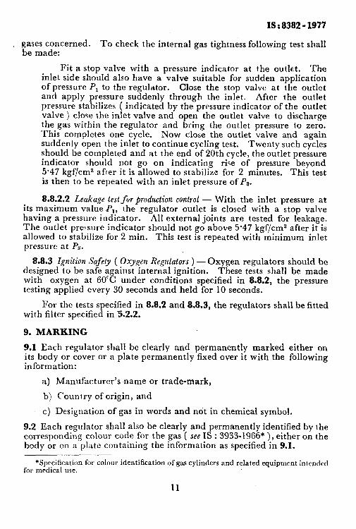
r;;;zcerned. To check the internal gas tightness following test shall
Fit a stop valve with a pressure indicator at the outlet. The inlet side should also have a valve suitable for sudden application of pressure P, to the regulator. Close the stop valve at the outlet and apply pressure suddenly through the inlet. After the outlet pressure stabilizes ( indicated by the pressure indicator of the outlet valve ) close the inlet valve and open the outlet valve to discharge the gas within the regulator and bring the outlet pressure to zero. This completes one cycle. Now close the outlet valve and again suddenly open the inlet to continue cycling test. Twenty such cycles should be completed and at the end of 20th cycle, the outlet pressure indicator should not go on indicating rire of pressure beyond 5.47 kgf/cm2 after it is allowed to stabilize for 2 minutes. This test is then to be repeated with an inlet pressure of Pa.
8.8.2.2 Leakage test for production control - With the inlet pressure at its maximum value P,, the regulator outlet is closed with a stop valve having a pressure indicator. All external joints are tested for leakage. The outlet pressure indicator should not go above 5.47 kgf/cm2 after it is allowed to stabilize for 2 min. This test is repeated with minimum inlet pressure at Pa.
8.8.3 Ignition S’ufefy ( Oxygen Regulators ) - Oxygen regulators should be designed to be safe against internal ignition. These tests shall be made with oxygen at 60°C under conditions specified in 8.8.2, the pressure testing applied every 30 seconds and held for 10 seconds.
For the tests specified in 8.8.2 and 8.8.3, the regulators shall be fitted with filter specified in 5.2.2.
9. MARKING
9.1 Each regulator shall be clearly and permanently marked either on its body or cover or a plate permanently fixed over it with the following information:
a) Manufacturer’s name or trade-mark,
b) Country of origin, and
c) Designation of gas in words and not in chemical symbol.
9.2 Each regulator shall also be clearly and permanently identified by the corresponding colour code for the gas ( see IS : 3933-1966* ), either on the body or on a plate containing the information as specified in 9.1.
*Specification for colour identification of gas cylinders and related equipment intended for medical use.
11
fS : 8382 - 1977
9.3 Each regulator may also be marked with the ISI Certification Mark.
NOTE - The use of the IS1 Certification Mark is governed by the provisions of the Indian Standards Institution (Certification Marks ) Act and the Rules and Regu- lations made thereunder. The IS1 Mark on products covered by an Indian Standard conveys the assurance that they have been produced to comply with the requirements of that standard under a well-defined system of inspection, testing and quality control which is devised and supervised by IS1 and operated by the producer. IS1 marked products are also continuously checked by IS1 for conformity to that standard as a further safeguard. Details of conditions under which a licence for the use of the IS1 Certification Mark may be granted to manufacturers or processors, may be obtained from the Indian Standards Institution.
IO. PACKING
10.1 Each regulator may be packed as agreed to between the purchaser and the supplier.
12
F