Embed Size (px)
Citation preview

Disclosure to Promote the Right To Information
Whereas the Parliament of India has set out to provide a practical regime of right to information for citizens to secure access to information under the control of public authorities, in order to promote transparency and accountability in the working of every public authority, and whereas the attached publication of the Bureau of Indian Standards is of particular interest to the public, particularly disadvantaged communities and those engaged in the pursuit of education and knowledge, the attached public safety standard is made available to promote the timely dissemination of this information in an accurate manner to the public.
इंटरनेट मानक
“!ान $ एक न' भारत का +नम-ण”Satyanarayan Gangaram Pitroda
“Invent a New India Using Knowledge”
“प0रा1 को छोड न' 5 तरफ”Jawaharlal Nehru
“Step Out From the Old to the New”
“जान1 का अ+धकार, जी1 का अ+धकार”Mazdoor Kisan Shakti Sangathan
“The Right to Information, The Right to Live”
“!ान एक ऐसा खजाना > जो कभी च0राया नहB जा सकता है”Bhartṛhari—Nītiśatakam
“Knowledge is such a treasure which cannot be stolen”
“Invent a New India Using Knowledge”
है”ह”ह
IS 778 (1984): Copper Alloy Gate, Globe and Check Valvesfor Waterworks Purposes [CED 3: Sanitary Appliances andWater Fittings]

IS : 778 - 1984( Reaffirmed 1995 )
Indian StandardSPECIFICATION FOR . 2010
COPPER ALLOY GATE, GLOBE AND CHECKVALVES fOR WATERWORKS PURPOSES
(Fourth Revision )
Fifth Reprint MARCH 1999
UDC 621.646.28+621.646.5[669.35]: 628.146.2
© Copyright 1986BUREAU OF INDIAN STANDARDSMANAK BHAVAN, 9 BAHADUR SHAH ZAFAR MARG
NEW DELHI-110002
Gr 7 January 1986
IS : 178 • 1984
Indian Standard
SPECIFICATION FORCOPPER ALLOY GATE, GLOBE AND CHECK
VALVES FOR WATERWORKS PURPOSES
( Fourth Revision)
Sanitary Appliances and Water Fittings Sectional Committee, DOC 3
Chairman
8mt K. D. MULEICAR
Representing
Municipal Corporation of Greater Bombay,Bombay
CHIEf ENGINEER
Menabers
ADVISER ( PHE ) Central Public Health & Environmental EnaineerIng Organization (Ministry of Works &Housing ), New Delhi
SURI S. K. BANERJEE National Test House, CalcuttaSHRI D. K. KANUNGO ( Alternate )
SHIU M. K. BASU Central Glass & Ceramiq Research Institute( CSIR ), Calcutta
Public Health Engineering Department, Government of Kerala, Trivandrum
Bombay Potteries & TIles Ltd, BombayEngineer-in-Chief's Branch, Army Headquarters,
New DelhiSURf K. V. KRISHNAMUanIV ( Alternate)
SHRJ P. JAOANATH RAo EID·Parry ( India) Ltd, M&drasSHRI M. MOOSA SULAIMAN ( Alternate)
SHJU A. F. KHAN Municipal Corporation of Greater Bombay,Bombay
DEPUTY HYDRAULIC ENGINEER (Alternate)
SHRI K. RAMACHANDRAN ( Alternate)CHIBP ENGINEER U. P. Jal Nigam, Lucknow
SUPERINTBNDINO ENGINEER ( Alternate)SHiU J. D' CRUZ Municipal Corporation of Delhi
SHRI S. A. SWAMY ( Alternate)DIRBCTORSHRI B. R. N. GUPTA
( Continued 01l]Hllt 2 )
co Copyright 1986BUREAU OF INDIAN STANDARDS
This publication is protected under tne Indian Copyright A(,t (XIV of 19.57) andreproduction in whole or in part by any means except with written permission of thepubliaher shall be deemed to bean infringement of copyright under the said Act.
IS : 778 • 1984
Repr.esenting
National Environmental Engineering ResearchInstitute ( CSJR ), Nagpur
Hindustan Shipyard ltd, Vishakhapatnam
National Buildings Organization (Ministry ofWorks & Housing ), New Delhi
Railway Board (Ministry of Railways), NewDelhi
Central Building Research Institute (CSIR),Roorkee
Hindustan Sanitaryware & Industries Ltd,Bahadurgarh
Central Public Works Department, NewDelhi
SUPVEYOIt OF WOtUCS I ( NDZ ) ( Alternate)SHRI R. THANJAN Directorate General of Technical Development,
New Delhi
SHRI R. K. SOMANY
SHRI J. SENGUPTA ( Alternate)SENIOR CIVIL EN(,I~EER ( WATER
SUPPLY)SHRI S. K. SHARMA
SHRI R. C. REDDY ( Alternate)SHRI K. LAKSHMINARAYANAN
SHRI A. SHARIFP ( Alternate)DR A. V. R. RAO
SURVEYOR OF WORKS ( NDZ )
( Continued from pilge J )
Members
SHRI S. R. KsHfRSAOAR
SHRI M. M. ALIKH~N ( Allt'lnate)SHRI T. N. UBOVEJA
SHRI G. RAMAN,Director ( Civ Engg )
Directorate General of Supplies & Disposals,New Delhi
Director General, lSI ( Ex-officio Member)
Secretary
SHRI C. K. BEBARTA
Joint Director ( Civ Eng ), lSI
Domestic and Municipal Water Fittings Subcommittee, DDC 3 : 2
HVDRAULIC E1'QI"EEft Municipal Corporation of Greater BombayDEPUTY HVD.{AULIC EN<..L'EER ( Alternate)
SHRI YASH RAJ AGGARWAL Goverdhan Das P.A. ( Calcutta ). CalcuttaSHRI JOGINDAR RAJ AGOARWAL (Alternate)
CHiEf E1'GII'tEER Bangalore Water Supply Sewerage Board,Bangalore
CUIEF ENC.I~EF~ Tamil Nadu Water Supply & Drainage Board,Madras
CUIEF E~G(~EEt{ Public Health Engineering Department, Govern-ment of Kerala, Trivandrum
eHUP ENG(~EEk U.P. Jal Nigam, LucknowSUPERINTE~DING ENGI!'lEER ( Alternate)
DIRECTOR Maharashtra Engineering Research Institute,Nasik
RESEARCH OFfiCER ( Alternate)SHRI J. D' CRUZ
SHRI S. A. SWAMY ( Alternate)Municipal Corporation ot Delhi, D~lhi
( Continued Oil page 2S)
2
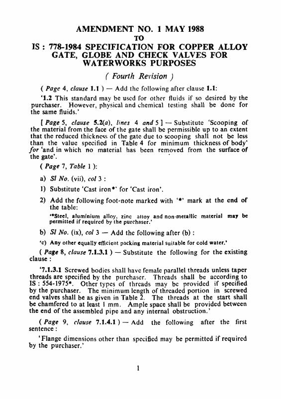
AMENDMENT NO. 1 MAY 1988TO
IS : 778-1984 SPECIFICATION FOR COPPER ALLOYGATE, GLOBE AND CHECK VALVES FOR
WATERWORKS PURPOSES
( Fourt/l Revision)
( Page 4, clause J.I ) - Add the following after clause 1.1:
'1.2 This standard may be used for other fluids if so desired by thepurchaser. However, physical and chemical testing shall be done forthe same fluids.'
[ Page 5, clause 5.2(a), lines 4 and 5 ] - Substitute 'Scooping ofthe material from the face of the gate shall be permissible up to an extentthat the reduced thickness of the gate due to scooping shall not be lessthan the value specified in Table 4 for minimum thickness of body'for 'and in which no material has been removed from the surface ofthe gate'. .
( Page 7, Table 1 ):
a) SI No. (vii), col 3 :
1) Substitute 'Cast iron?" for 'Cast iron'.
2) Add the following foot-note marked with '.' mark at the end ofthe table:··Steel. aluminium alloy, zinc alloy and non-metallic material may bepermitted if required by the purchaser.'
b) 51 No. (ix), col 3 - Add the following after (b) :
'e) Any other equally efficient packing material suitable for cold water.'
( Page 8, clause 7.1.3.1 ) - Substitute the following for the existingclause:
'7.1.3.1 Screwed bodies shall have female parallel threads unless taperthreads are specified by the purchaser. Threads shall be according toIS : 554-1975*. Other types of threads may be provided if specifiedby the purchaser. The minimum length of threaded portion in screwedend valves shall be as given in Table 2. The threads at the start shallbe chamfered to at least 1 mm. Ample space shall be provided betweenthe end of the assembled pipe and any internal obstruction.'
(Page 9, clause 7.1.4.1) - Add the following after the firstsentence:
'Flange dimensions other than specified may be permitted if requiredby the purchaser.'
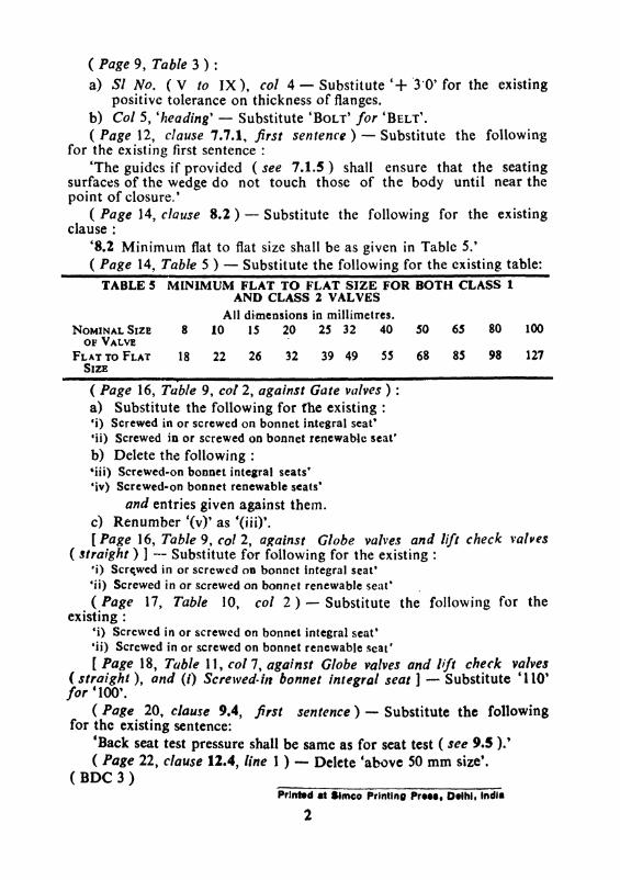
( Page 9, Table 3 ) :
a) 81 No. (V to IX), col 4 - Substitute '+ '3'0' for the existingpositive tolerance on thickness of flanges.
b) Col 5, 'heading' - Substitute 'BOLT' for 'BELT'.
( Page 12, clause 7.7.1, first sentence) - Substitute the followingfor the existing first sentence:
'The guides if provided (see 7.1.5) shall ensure that the seatingsurfaces of the wedge do not touch those of the body until near thepoint of closure.'
( Page 14, clause 8.2) - Substitute the following for the existingclause:
'8.2 Minimum flat to flat size shall be as given in Table 5.'( Page 14, Table 5 ) - Substitute the following for the existing table:
127988S68ss39 4932262218
TABLE 5 MINIMUM FLAT TO FI.,AT SIZE FOR BOTH CLASS 1AND CLASS 2 VALVES
All dimensions in rnillimetres.8 10 IS 20 25 32 40 50 65 80 100NOMINAL SIZE
OF VALVE
FLAT TO FLATSIZE
( Page 16, Table 9, co/2, against Gate valves) :a) Substitute the following for the existing:'i) Screwed in or screwed on bonnet integral seat''ii) Screwed in or screwed on bonnet renewable seat'b) Delete the following:'iii) Screwed-on bonnet integral seats"'iv) Screwed-on bonnet renewable seats'
and entries given against them.e) Renumber '(v)' as '(iii)'.[Page 16, Table 9, (01 2, against Globe valves and lift check valves
( straight ) 1- Substitute for following for the existing:·i) Screwed in or screwed on bonnet integral seat''ii) Screwed in or screwed on bonnet renewable seat' ,(Page 17, Table 10, col 2) - Substitute the following for the
existing:"i) Screwed in or screwed on bonnet integral seat'Iii) Screwed in or screwed on bonnet renewable scat'[ Page 18, Table 11, col 7, against Globe valves and /1ft check valves
( straight), and (I) Screwed-in bonnet integral seat] - Substitute '110'for '100'.
(Page 20, clause 9.4, first sentence) - Substitute the followingfor the existing sentence:
'Back seat test pressure shall be same as for seat test ( see 9.5 ).'( Page 22, clause 12.4, line 1 ) - Delete 'above SO mm size'.
(DDC 3)PrJnted at .'mco Printing Pr•••• Deihl, Indl.
2
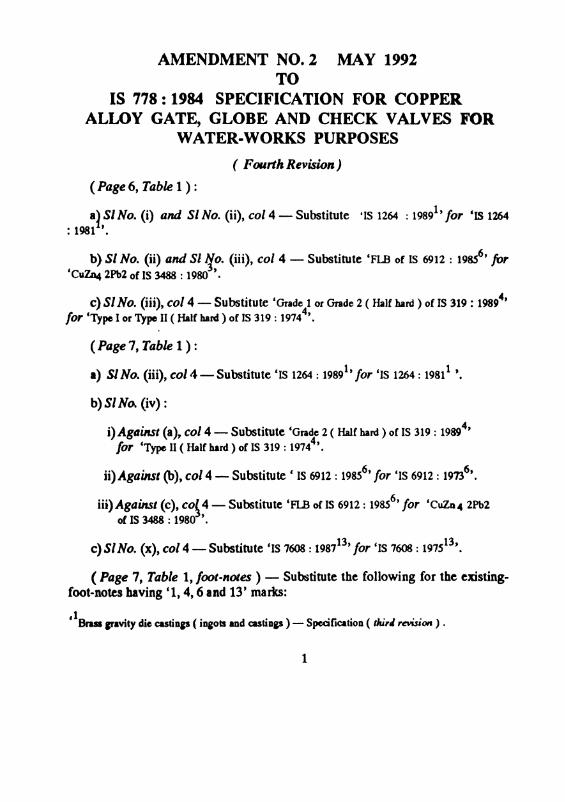
AMENDMENT NO. 2 MAY 1992TO
IS 778: 1984 SPECIFICATION FOR COPPERALLOY GATE, GLOBE AND CHECK VALVES FOR
WATER-WORKS PURPOSES
( Fourth Revision)
( Page6, Table1 ) :
a}51No. (i) and 51No. (ii), col 4 - Substitute 'IS 1264 : 19891, for 'IS 1264
: 1981 '.
b) 51No. (ii) and 51 /f,o. (iii), col 4 - Substitute 'FLB of IS 6912 : 19S56, for
'CuZD.4 2Pb2 of IS 3488 : 1980 '.
c) 51No. (iii),col 4 - Substitute 'Grade 1 or Grade 2 ( Half hard ) of IS 319 : 19894,
for 'Type I or Type II (Half bard) of IS 319 : 19744, .
(Page?, Table1):
I) Sl No. (iii), col 4 - Substitute 'IS 1264 : 19891, for 'IS 1264 : 1981
1'.
b) 51 No. (iv) :
i) AgtlUtst (a), col 4 - Substitute 'Grade 2 ( Half hard ) of IS 319 : 19894,
for 'Type II ( Half hard) of IS 319 : 19744,.
ii)Against(b),col 4 - Substitute C IS 6912 : 19856
, for 'IS 6912 : 19736
, .
iii)Against (c), co~4 - Substitute 'FI..B of IS 6912 : 19S56, for 'CuZD4 2Pb2
of IS 3488 : 1980 '.
c) 51No. (x), col 4 - Substitute 'IS 7608 : 198713, for 'IS 7608 : 1975
13, .
(Page 7, Table 1, foot-notes) - Substitute the following for the existingfoot-notes having '1, 4,6 and 13' marks:
'lBrus If.vity die castiDp ( iDeOIS and castiDp) - Specification ( tJU,J revision) .
1
4FreeCUttiDI brassbars, rodsand sections- Specification (fOlU'tlt revision ).
6SpecifiCAtiOO for copperaDd copperalloyfOM sto<X aDd forginp ( farst revision ).
13Specificatioll for phosphor broue wireI for paeral eOlioeeriol purposes (first revUiOlJ).'
(CE03 )
Printed at SimcoPrintinaPress, Delhi
2
AMENDMENT NO.3 NOVEMBER 2005TO
IS 778: 1984 SPECIFICATION FOR COPPER ALLOYGATE, GLOBE AND CHECK VALVES FOR WATER
WORKS PURPOSES
( Fourth Revision)
(Page 22, clause13.1, line 2 ) - Delete 'either 4 and 'or stamped'.
(CED 3)
Reprography Onll, BIS, New lJelhl, trima
IS : 778 - 1984
Indian Standard
SPECIFICATION FORCOPPER ALLOY GATE, GLOBE AND CHECK
VALVES FOR WATERWORKS PURPOSES
( Fourth Revision)o. FOR E W 0 R D
0.1 This Indian Standard (Fourth Revision) was adopted by the IndianStandards Institution on 29 June 1984, after the draft finalized by theSanitary Appliances and Water Fittings Sectional Committee had beenapproved by the Civil Engineering Division Council.
0.2 This standard was first published in 1957 and subsequently revised in1964. 1971 and 1980. This revision of this standard has been taken up toincorporate changes found necessary in the light of the comments receivedon the standard. This includes modifications relating to materials forvarious components, modifications in the face-to-face dimensions offtangedvalves. A clause on sampling has also been added.
0.3 Except the gates for gate valves all other essential parts which aresubject to wear shall be interchangeable for the same size and type of thevalves.
0.4 With a view to guiding the purchaser, recomrnendations on the information to be supplied by a purchaser in an enquiry or order of the valves isgiven in Appendix A.
0.5 This standard contains clauses 7.1.4.2 and 12.1 which permit thepurchaser to use his option for selection to suit his requirements.
0.6 For the purpose of deciding whether a particular requirement of thisstandard is complied with, the final value.. observed or calculated, expressing the result of a test, shall be rounded off in accordance with IS: 2-1960•.The number of significant places retained in the rounded ofT value shouldbe the same as that of the specified value in this standard.
*RultS for rounding off numerical values ( revised v.
3
IS : 778 - 1984
1. SCOPE
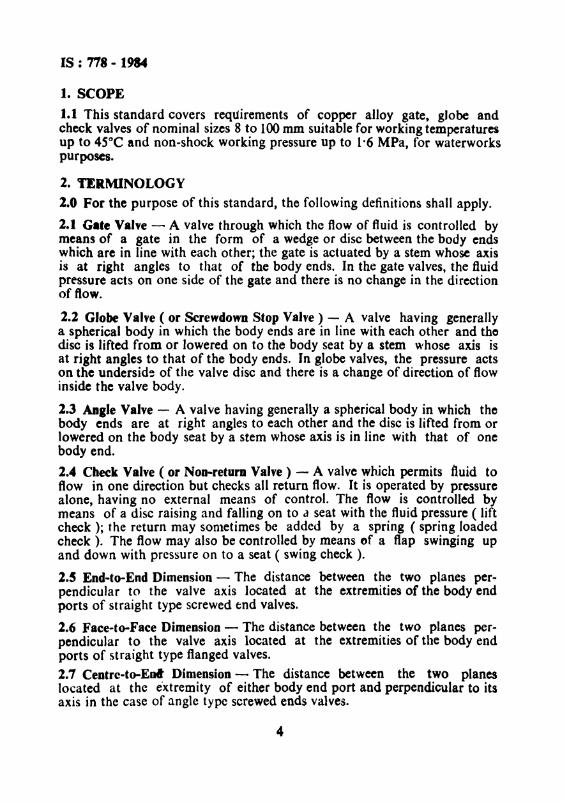
1.1 This standard covers requirements of copper alloy gate, globe andcheck valves of nominal sizes 8 to 100 mm suitable for working temperaturesup to 4SoC and non-shock working pressure up to 1·6 MPa, for waterworkspurposes.
2. TERMINOLOGY
2.0 For the purpose of this standard, the following definitions shall apply.
2.1 Gate Valve - A valve through which the flow of fluid is controlled bymeans of a gate in the form of a wedge or disc between the body endswhich are in line with each other; the gate is actuated by a stem whose axisis at right angles to that of the body ends. In the gate valves, the fluidpressure acts on one side of the gate and there is no change in the directionof ftow.
2.2 Globe Valve ( or Screwdown Stop Valve) - A valve having generallya spherical body in which the body ends are in line with each other and thedisc is lifted from or lowered on to the body seat by a stem whose axis isat right angles to that of the body ends. In globe valves, the pressure actson the underside of the valve disc and there is a change of direction of flowinside the valve body.
1.3 Anile Valve - A valve having generally a spherical body in which thebody ends are at right angles to each other and the disc is lifted from orlowered on the body seat by a stem whose axis is in line with that of onebody end.
2.4 Check Valve ( or Non-return Valve) - A valve which permits fluid toflow in one direction but checks all return flow. It is operated by pressurealone, having no external means of control. The flow is controlled bymeans of a disc raising and falling on to a seat with the fluid pressure ( liftcheck ); the return may sometimes be added by a spring ( spring loadedcheck). The flow may also be controlled by means ef a flap swinging upand down with pressure on to a seat ( swing check ).
2.5 End-to-End Dimension - The distance between the two planes perpendicular to the valve axis located at the extremities of the body endports of straight type screwed end valves.
2.6 Face-to-Face Dimension - The distance between the two planes perpendicular to the valve axis located at the extremities of the body endports of straight type flanged valves.
2.1 Centrc-to-Eni Dimension - The distance between the two planeslocated at the extremity of either body end port and perpendicular to itsaxis in the case of angle type screwed ends valves.
4
IS : 778 - 1984
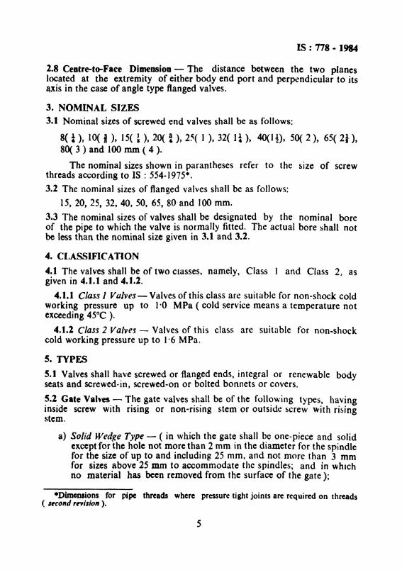
2.8 Centre-to-Face Dimension - The distance between the two planeslocated at the extremity of either body end port and perpendicular to itsaxis in the case of angle type flanged valves.
3. NOMINAL SIZES3.1 Nominal sizes of screwed end valves shall be as follows:
8( i ), 10( J), 15( ~ ), 20( ~ ), 2~( 1 ), 32( 1i), 4O(1l ), 50( 2), 65( 21 ),80( 3 ) and 100 rom ( 4 ).
The nominal sizes shown in parantheses refer to the size of screwthreads according to IS : 554-)975*.
3.2 The nominal sizes of flanged valves shall be as follows:
15, 20, 25, 32, 40, 50, 65, 80 and 100 mm,
3.3 The nominal sizes of valves shall be designated by the nominal boreof the pipe to which the valve is normally fitted. The actual bore shall notbe less than the nominal size given in 3.1 and 3.2.
4. CI,ASSIFICATION
4.1 The valves shall be of two Classes, namely, Class ) and Class 2, asgiven in 4.J.l and 4.1.2.
4.J.l Class 1 Valves- Valves of this class are suitable for non-shock coldworking pressure up to 1'0 MPa ( cold service means a temperature notexceeding 45°C ),
4.1.2 Class 2 Valves - Valves of this class are suitable for non-shockcold working pressure up to 1'6 MPa.
5. TYPES5.1 Valves shall have screwed or flanged ends, integral or renewable bodyseats and screwed-in, screwed-on or bolted bonnets or covers,
5.1 Gate Valves - The gate valves shall be of the following types, havinginside screw with rising or non-rising stem or outside screw with risingstem.
a) Solid Wedge Type - ( in which the gate shall be one-piece and solidexcept for the hole not more than 2 mm in the diameter for the spindlefor the size of up to and including 25 rnm, and not more than 3 mmfor sizes above 2S mm to accommodate the spindles; and in whichno material has been removed from the surface of the gate );
-Dimensions for pipe threads where pressure tight joints are required on threads( "cond ,nilio" ).
5
IS : 778 - 1984
b) Split wedge type; andc) Double disc type.
S.3 Globe Valves - The globe valves shall be of the following types havingrising stem with inside or outside screw:
a) Straight type, and
b) Right angle type.
5.4 Check Valves - The check valves shall be of the following types:
a) Swing type ( for use with the axis of the body end ports horizontalor vertical ) ( see Note); and
b) Lift type with disc or ball check ( for use with the axes of the bodyend ports horizontal or vertical or in applications where the axis ofthe body end ports are at right angles ).
NOTE - Swing check valves may also be used in vertical direction when the flowis in the upward direction.
6. MATERIALS
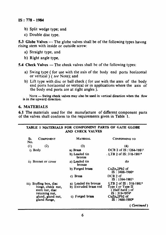
6.1 The materials used for the manufacture of different component partsof the valves shall conform to the requirements given in Table 1.
TABLE 1 MATERIALS FOR COMPONENT PARTS OF GATE GLOBEAND CHECK VALVES
SL COMPONENTNo.(I) (2)
i) Body
ii) Bonnet or cover
iii) Stuffing box, dischinge, check nut,stem nut t discretaining nut,gland, gland nut,gland flange,
MATBRIAL
(3)a) Brassb) Leaded tin
bronzea) Leaded tin
bronzeb) Forged brass
c) Brass
a) Leaded tin bronzeb) Extruded brass rod
C) Forged brass
6
CONFORMING TO
(4)DeB 2 of IS: 1264-198P
. LTB 2 of IS: 318.19811
do
CuZoc2Pb2 ofIS : 3488·1980'
DCB 2 ofIS : 1264-1981 l
LTB 2 of IS : 318-1981 1
Type I or Type U( Half hard ) ofIS : 319-t974(
CUZn,2Pb2 ofIS : 3488-198()1
( Continued)
IS : 778 - 1984
TABLE 1 MATERIALS FOR COMPONENT PARTS OF GATE GLOBEAND CHECK VALVES - Contd.
Property clauses 4.6and 4 ofIS : 1367-1967'
FG 200 ofIS : 210-1978'
Grade C ofIS: 2712-197(1u
IS : 5414-1969 11
IS : 4687-198011
IS : 7608-1975 11
Type II ( Half hard)of IS : 319-1974-
HT lor AT 2 ofIS : 320-19806
FHTB J and FHTB 2of IS : 6912-1973'
C"uZn~2Pb2 ofIS : 3488-1.98Q1
IS : 4398-19727
CONI-'ORMING TO
(4)DeB 2 of
IS .: 1264-198 J1
Chromium steel
Mild steel
Cast iron
c) Forged brass
a) Extruded brassrod
b) High-tensile brass
MATERIAl..
(3)d) Brass
x) Spring
v) Ball ( for ball typecheck valves)
vi) Bolts, nuts
ix) Gland packing
vii) Handwheel
viii) Gasket
SL. No. COMPONENT
(1) (2)body seat ringsand disc or wedgefacing rings (whererenewable)
iv) Stem, hinge pin andplug
Compressedasbestos fibrea) Hemp and juteb) AsbestosPhosphor bronzewire
xi) Seating ring Synthetic rubber IS : 5 t92-1975 1&
lSpecification for brass ingots for gravity die castings and brass gravity dre castings( including naval brass) ( second revision ).
'Specification for leaded tin bronze, ingots and castings ( second revision ).
·Specification for brass bars, rods and sections suitab Ie for forging (first revision ).·Specification for free-cutting brass bars, rods and sections ( third revision ).'Specification for high tensile brass rods and sections ( second revision ).'Specification for copper alloy and forgings.'Specification for carbon-chromium steel for the manufacture of balls, rollers and
bearing races i first revision ).'Specitlcation for technical supply conditions for threaded fasteners (fi rst revision j.
'Specification for grey iron castings ( third revision ).lOSpecification for compressed asbestos fibre jointing ( second revision ).lISpecification for gland packing, jute and hemp.12Specification for gland packing asbestos.I'Specification for phospher bronze wires ( for general engineering purposes ).ltSpecification for vulcanized natural rubber based compounds ( first revision ).
7
IS : 118 - 1984
7. DESIGN AND MANUFACTURE
7.1 Valve Bodies- The design of the valve bodies shall be such as willprovide ample resistance to distortion under maximum cold workingpressure.
7.1.1 Body End Ports - The body end ports shall be circular and of adiameter not less than the nominal size of the valve.
7.1.2 Water-Way Area - The area of the water-way through and between the ports of the valve shall be not less than the area of a circle ofdiameter equal to the nominal size of the valve. However, the area ofthe water-way may be reduced through the valve seats. in the case of globevalves and check valves to 85 percent of the full water-way area. Thearea of flow through the gate valve with renewable seats may be reducedto the extent that it is equal to the area of a circle of diameter not lessthan seven eighths of the nominal size of the valve.
1.1.3 Screwed Body Ends - The ends of the bodies of screwed endvalves shall be externally in the form of a hexagon or round with four ormore protruding ribs to facilitate wrenching.
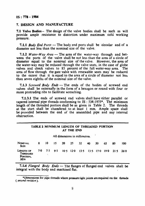
1.1.3.1 The ends of screwed end valves shall have either parallel ortapered internal pipe threads conforming to IS : 534-1975*. The minimumlength of the threaded portion shall be as given in Table 2. The threadsat the start shall be chamfered to at least 1 rom. Ample space shallbe provided between the end of the assembled pipe and any internalobstruction.
TABLE 1, MINIMUM LENGTH OF THREADED PORTIONAT THE END
All dimensions in millirnetres.
NOMINAL 8 10 IS 20 25 32 40 SO 6S 80 100SIZE
LBNOTH OP 7'0 7'5 9'5 JO·5 12'0 13·S 13'5· 17'0 19·0 21·5 26-0THRBADEDPoRTION,Min
7.1~4 Flanged Body Ends - The flanges of flanged end valves shall beintegral with the body and machined flat.
•Dimensions for pipe threads where pressure tight joints are required on the threads( second revision).
IS : 778 - 1984
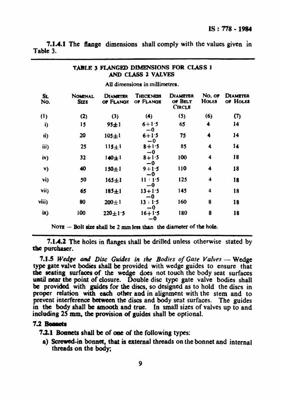
7.J.4.1 The flange dimensions shall comply with the values given InTable 3.
TABLE 3 FLANGIID DIMENSIONS FOR eLM S IAND CLASS 2 VALVES
AUdimensions in Inillimetres.
SL NOMINAL DIAMlTBR THJClCNBSS DIAMBTBR No.o. DIAMBTBR
No. SIZE 0. FLANGE 0. FUNGB Of BELT HOLES O. HOLESC'lRCLB
(I) (2) (3) (4) (5) (6) (7)
i) ]~ 95:1: 1 6+1·~ 6S 4 14-0
Ii) 20 JOs±t 6+1·' 7S 4 14-0
iii) 25 11S±t 8+1'5 85 4 14-0
iv) 32 J40:*1 8+1'5 100 4 18-0
v) 40 lSO±l 9+1-5 110 4 18-0
vi) SO 165±1 11 I I-S 125 4 18-0
vii) 65 185:1:1 13+ I-S 14S 4 18-0
viii) 80 200±1 13 t I-S 160 8 18-0
ix) 100 220±loS 16+ 1·5 180 8 18-0
NOTE - Bolt size Ihall be2 mm less than the diameter of the hole.
7.1A.2 The holes in flanges shall be drilled unless otherwise stated bythe purcbaacr.
1.1.5 Wedge tmd Disc Guides in the Bodies of Gate Valves - Wedgetype gate valve bodies shall be provided with wedge guides to ensure thatthe seatinl surfacesof the wedge does not touch the body seat surfacesuntil near the point of closure. Double disc type gate valve bodies shallbe provided with guides for the discs, so designed as to hold the discs inproper relation with each other and in alignment with the stem and toprevent interference between the discs and body seat surfaces. The guidesin the body shall be smooth and true. In small sizes of valves up to andincludioS 25mm, theprovision of guides shall be optional.
7:J, Bo8IIets7.2.1 Bonnets shall be of one of the following types:
a) Screwed-in bonnet, that is external threads on the bonnet and internalthreads on the body;
9
IS : 718 - 1984
b) Screwed..on bonnet, that is internal threads on the bonnet and external threads on the body; and
c) BoIted bonnet.
7.2.1.1 Screwed-on bonnet may be one-piece or two...piece unioncoupling type.
7.2.1.2 In screwed-in and screwed-on bonnets, the engagement ofthreads shall be adequate to withstand the maximum cold working pressure. Minimum number of engaged threads shall be five for valve sizesup to 32 mm ( inclusive) and eight for sizes above 32 mm, Minimumpitch of threads shall be I· 5 mm.
7.2.1.3 The surface forming the body-to-bonnet joint shall be machinedsmooth, The joint may be metal to metal or with a gasket.
7.2.2 Bonnet Flanges - Flange on the bonnet and corresponding flangeon the body for bolted bonnet joint shall be sufficiently thick to provide aleak-proof joint when the valve is operated continuously under themaximum cold working pressure. The flanges shall in no case be thinnerthan the nominal diameter of the bolts used for connecting these flanges.
7.2.3 Bonnet Bolting - Body..bonnet bolted joint shall be secured byusing fasteners of one of the following types:
a) Headed bolt with nut.
b) Stud bolt with nut at each end, and
c) Stud fitted wrench-tight in the body flange with nut.
7.2.3.1 Bolts or studs less than MIO for valve sizes up to and including 25 nun and MI2 for valve sizes above 25 mm shall not be used.
7.3 Stuffing Box - The stuffing box may be made integral with the bonnetor it may be incorporated as separate component secured to the bonneteither by screwing or by bolting. A suitable recess either in the bonnetor in the stuffing box shall be provided to accommodate the spindle collarin the case of non-rising spindle valves.
7.4 Gland - Gland shall be of one-piece or two-piece design consistingof a sleeve sliding in the stuffing box and secured by a gland nut or boltedflange.
7.4.1 When the gland is secured by the gland nut, the gland nut shall beexternal in the form of a hexagon which shall conform, as far as possible,to a standard nut size.
10
IS : 778 - 1984
7.5 Back Seat - The gate and globe valves shall permit 'on-line' replacement of the gland packing under the maximum cold working pressurewithout showing any leakage through the stuffing box when the valve is infull open position. Back seat may be provided on the stern or on the discin case of globe valves.
7.6 Stem
7.6.1 The stem shall be in one piece and shall be designed to prevent thewedge or disc from leaving the stem.
7.6.2 The threads on the stem shall be of square or trapezoidal form,preferably conforming to IS: 4694-1968·, IS: 7008 ( Part 3 )-1973t andIS : 7008 (Part 4 )-1973:. Stem of 8 and 10 mm size valves mayhave screw threads conforming to IS : 4218 ( Part 3 ).. 1967§ and IS : 4218( Part 4 )-196711.
7.6.3 The minimum length of the actuating threads in engagement atthe open or closed position of the valve shall be two-thirds of the externaldiameter of the threads.
7.6.4 'The total length of the stem shall be such that the handwheel isfreely gripped by hand when the valve is closed and also repacking of thegland is possible without taking off the handwhcel when the valve is fullopen.
7.6.5 The upper end of the stem or yoke-sleeve (in the case of risingstem, non-rising handwheel gate valves) shall be provided with a taperedsquare for mounting the handwheel. The handwheel shall be held in placeby a nut and washer screwed on to the stern or yoke-sleeve or by a setscrew and washer.
7.6.6 Rising Stem - An annular seat machined to contact the backseatin the bonnet shall also be provided integral with the stem in case backseatarrangement is intended to be provided on the stein.
7.6.6.1 The stem rising through the handwheel shall be of sufficientlength to at least flush with the top of the yoke-sleeve when the wedge ordisc is worn out to the lowest possible position.
7.6.7 Non-rising Stem - The stem shall be provided with an integralthrust collar machined smooth to provide a pressure- tight seal against the----_. -
·Specification for basic dimensions for square threads.t ISO metric trapezcldal screw threads: Part 3 Basic dimensions for design profiles.tISO metric trapezoidal screw threads: Part 4 Tolerancing system.§ISO metric screw threads: Part 3 Bulc dimensions for design profiles.IIISO metric screw threads: Part 4 Tolerancing system.
11
IS : 778 - 1984
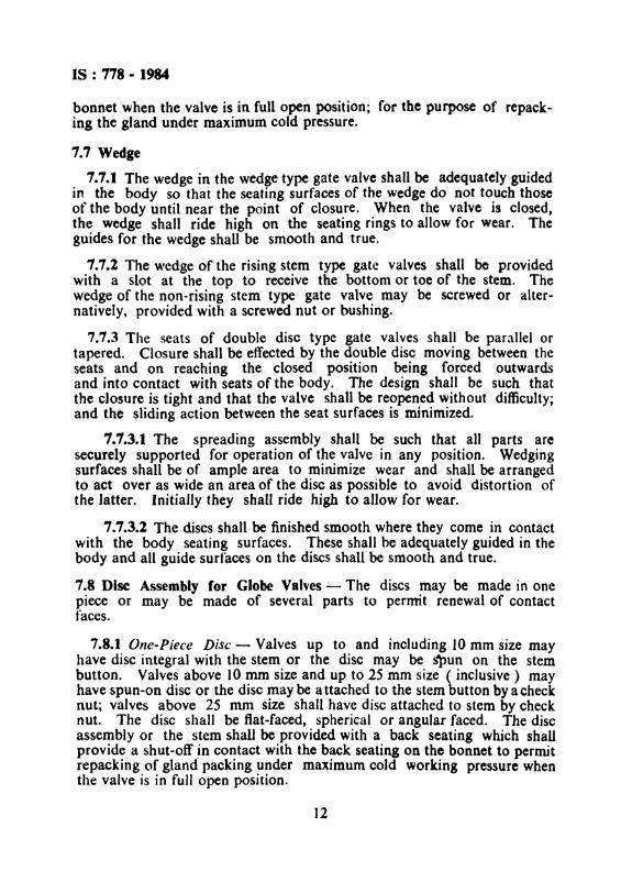
bonnet when the valve is in full open position; for the purpose of repacking the gland under maximum cold pressure.
7.7 Wedge
7.7.1 The wedge in the wedge type gate valve shall be adequately guidedin the body so that the seating surfaces of the wedge do not touch thoseof the body until near the point of closure. When the valve is closed,the wedge shall ride high on the seating rings to allow for wear. Theguides for the wedge shall be smooth and true.
7.7.2 The wedge of the rising stem type gate valves shall be providedwith a slot at the top to receive the bottom or toe of the stem. Thewedge of the non-rising stem type gate valve may be screwed or alternatively, provided with a screwed nut or bushing.
7.7.3 The seats of double disc type gate valves shall be parallel ortapered. Closure shall be effected by the double disc moving between theseats and on reaching the cLosed position being forced outwardsand into contact with seats of the body. The design shall be such thatthe closure is tight and that the valve shall be reopened without difficulty;and the sliding action between the seat surfaces is minimized.
7.7.3.1 The spreading assembly shall be such that all parts aresecurely supported for operation of the valve in any position. Wedgingsurfaces shall be of ample area to minimize wear and shall be arrangedto act over as wide an area of the disc as possible to avoid distortion ofthe latter. Initially they shall ride high to allow for wear.
7.7.3.2 The discs shall be finished smooth where they come in contactwith the body seating surfaces. These shall be adequately guided in thebody and all guide surfaces on the discs shall be smooth and true.
7.8 Disc Assembly for Globe Valves - The discs may be made in onepiece or may be made of several parts to permit renewal of contactfaces.
7.8.1 One-Piece Disc - Valves up to and including 10 mm size mayhave disc integral with the stem or the disc may be spun on the stembutton. Valves above 10 nun size and up to 25 mm size ( inclusive) mayhave spun-on disc or the disc may be a ttached to the stem button by a checknut; valves above 25 mm size shall have disc attached to stem by checknut. The disc shall be fiat-faced, spherical or angular faced. The discassembly or the stem shall be provided with a back seating which shallprovide a shut-off in contact with the back seating on the bonnet to permitrepacking of gland packing under maximum cold working pressure whenthe valve is in full open position.
12
IS : 778 - 1984
7.8.2 Renewable Disc Assembly - The renewable disc assembly shall ingeneral consist of the following:
a) Disc holder,
b) Disc,
c) Disc guide,
d) Check nut, and
e) Disc retaining nut with washer.
The disc holder, disc and nut may be made in single renewable castingwhere so desired. The disc in a renewable disc assembly shall be of flatfaced, spherical or angular-faced design. A back seating shall be providedon the disc holder or on the stem to form a shut-off in contact with theback seat on the bonnet to permit repacking of gland packing undermaximum cold working pressure when the valve is full open.
7.9 Disc for Check Valves -- The disc for check valve may be in one-pieceor in several pieces to permit renewal of contact faces. This may beverticallift type guided by a pin above or below the disc, or may be of swing typeor in the form of a ball.
7.9.1 Disc of globe and check valve may be provided with renewablesynthetic rubber seating ring.
7.10 Body Seats
7.10.1 The seats may be integral with the body or may be separaterenewable seat rings, screwed-in to the body and shall have lugs or slotsto facilitate renewal. Seat ring faces shall be finished smooth and edgesshall be deburred.
7.11 Handwheel - Handwheel shall close the valve by turning in clockwisedirection when facing the wheel. Handwheel shall be marked with the word'OPEN' or 'SHUT' with arrow to indicate direction of opening or closing.Alternatively, these markings may be shown on a plate secured below thehandwheel nut.
8. DIMENSIONS
8.1 l\'Unimum Thickness of Body and Bonnet - The wall thickness at anypoint of body and bonnet, including cover and disc subjected to directfluid pressure shall be not less than that given in Table 4.
8.1.1 The thicknesses in Table 4 are minimum and they shall beincreased to provide for additional strength whenever required, to provide
13
IS : 778 1984
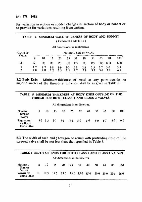
for variation in section or sudden changes in section of body or bonnet orto provide for variations resulting from casting.
TABLE 4 MINIMlIM WA.LL THICKNESS OF BODY AND BONNET
( Co/uses R.l and 8.1.1 )
AU dimensions in millirnetres.
("LASS OF NOMINAL SIZE OF VAI. VEVALVE ,--- --- ~----- -_._- A ----- ---~
8 lOIS 20 25 32 40 50 65 80 100
(1) (2) (3) (4) (5) (6) (7) (8) (9) (10) (11) (12)
1 1'7 1'7 1'8 1-9 2-0 2'2 2-3 2'5 2'7 3'0 3-52 2'0 2-0 2-2 2'3 2-S 2'7 2'9 3'2 3-6 3-9 4-5
8.2 Body Ends - Minimum thickness of metal at any point outside themajor diameter of the threads at the ends shall be as given in Table 5.
TABLE 5 MINIMUM THICKNESS AT BODY ENDS OUTSIDE 0." THETHREAD FOR BOTH CLASS 1 AND CLASS 1 VALVES
All dimensions in millirnetres.
NOMINAL 8 10 15 20 25 32 40 50 65 80 100SIZB OPVALVE
THICKNESS 3-2 3'3 3'7 4'J 4'6 50 5'0 6'0 6'7 7'5 9'0AT BODYENDS, Milt
8.3 The width of each end ( hexagon or round with protruding ribs) of thescrewed valve shall be not less than that specified in Table 6.
T.ABLE 6 WIDTH OF ENDS FOR BOTH CLASS I AND CLASS Z VALVES
All dimensions in millimetres.
NOMINAL 8 10 1~ 20 2S 32 40 50 65 80 100SIZE OPVALVE
WIDTH OP 10 10-~ II'S 13'0 13'0 IS'O lS'O 20'0 21-0 23'S 26-0ENDS, Min
14
IS : 778 - J984
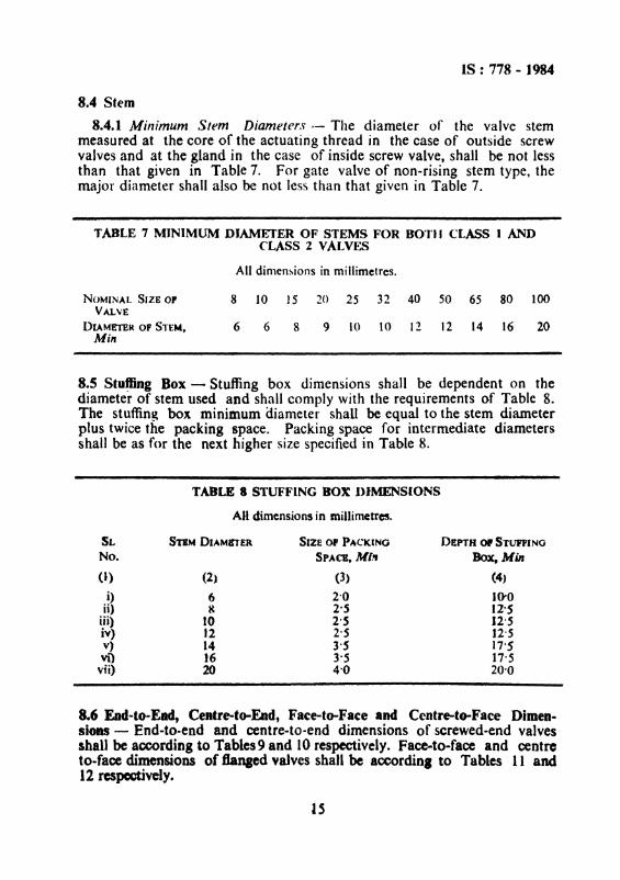
8.4 Stem
8.4.1 Minimum Stem Diameters t- The diameter of the valve stemmeasured at the core of the actuating thread in the case of outside screwvalves and at the gland in the case of inside screw valve, shall be not lessthan that given in Table 7. For gate valve of non-rising stem type, themajor diameter shall also be not less than that given in Table 7.
TABLE 7 MINIMUM DIAMETER OF STEMS FOR BOTJI CI ..ASS 1 ANDCLASS 2 VAtVES
All dimensions in millimetres,
NOMINAL SIZE 0' 8 10 ]5 20 25 32 40 50 65 80 100VALVE
DIAMETER OF STEM, 6 6 8 9 10 10 12 12 14 16 20Min
8.5 Stu~ng Box - Stuffing box dimensions shall be dependent on thediameter of stem used and shall comply with the requirements of Table 8.The stuffing box minimum diameter shall be equal to the stem diameterplus twice the packing space. Packing space for intermediate diametersshall be as for the next higher size specified in Table 8.
TABLE 8 STUFFING BOX !)IMENSIONS
All dimensions in millimcttres..
SLNo.
(I)
i)ii)
iii)iv)v)vi)
vii)
STIM DIAMITER
(2)
68
1012141620
SIZE 0' PACKING
SPACE. Mb.
(3)
2·02'S2·S2·53·S3'54·0
DEPTH Of STUFfiNG
Box, Min
{4,
10-012'S12·S12·517'517'520-0
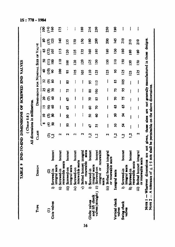
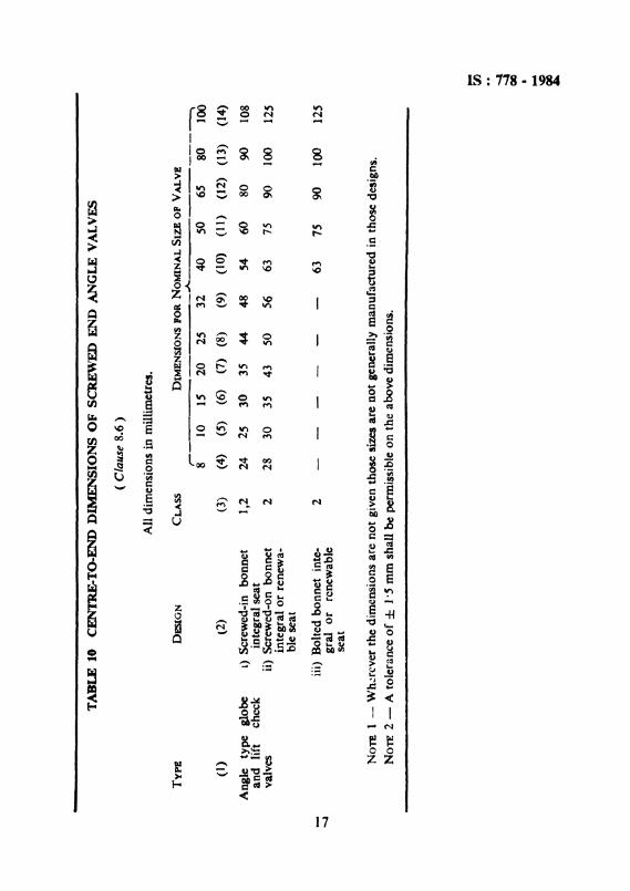
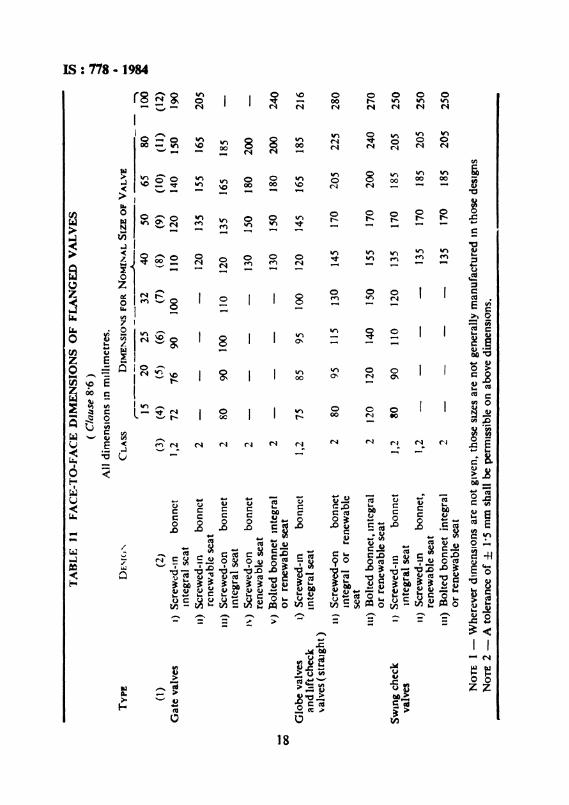
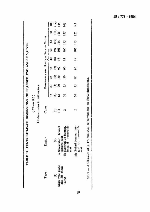
8.6 End-to-Ead, Centre-to-End, Face-to-Face and Centre-to-Face Dimensions - End-to-end and centre-to-end dimensions of screwed-end valvesshall beaccording to Tables 9 and 10respectively. Face-to-face and centreto-face dimensions of flanaed valves shall be accordinl to Tables 11 and12 respectively.
IS
TA
BL
E'
EN
D-T
()..E
NJ)
DIM
EN
SIO
NS
OF
SC
RE
WE
DE
ND
VA
LV
ES
.. rn(
Cla
use
8.6
)..
AU
dim
ensi
ons
inm
iDim
etre
s.;I
TYPE
DE
SIO
NC
LAss
DIM
EN
SIO
NS
POR
NO
MIN
AL
SIZ
EO
PV
AL
VE
• ....r-
---A
---~
!8
10IS
202S
3240
SO6S
8010
0(I
)(2
)(3
)(4
)(5
)(6
)(7
)(8
)(9
)(t
o)
(11)
(12)
(13)
(14)
Gat
eva
lves
i)Sc
rew
ed-i
nb
on
net
1,2
SO50
6060
7080
9010
0lO
S12
S16
0in
tegr
alse
ats
li)S
crew
ed-i
nbo
nnet
2-
--
--
-10
011
01
JS14
017
Sre
new
able
seat
siii
)Sc
rew
ed.o
nbo
nnet
2SO
SO6S
6575
8S95
100
120
13S
inte
gral
seat
siv
)S
crew
ed-o
nbo
nnet
2-
--
--
-10
512
013
5IS
Ore
new
able
seat
.v)
Bol
ted
bonn
etin
tqra
l2
--
--
--
lOS
120
135
ISO
180
....or
rene
wab
leee
ata
0\
Glo
beva
lve.
i)Sc
rew
ed·in
bonn
et1,
247
SO60
7080
9511
012
S16
018
021
6an
dlif
tch
eck
inte
gral
seat
sv
ah
a(I
trai
aht)
ii)S
crew
ed-o
nbo
nnet
1..2
5560
708S
100
115
125
ISO
180
200
250
inte
gral
or
rene
wab
lese
ats
iii)
Bol
ted
bonn
etin
tep
2-
--
--
-12
SIS
O18
020
025
0o
rre
new
able
teat
sV
ert
ica
lche
ckIn
tear
alle
ats
1,2
SOSO
6'70
758S
9511
013
014
519
0va
lves
Sw
illl
chec
ki)
Scr
ewaI
-in
bo
nn
et1,
254
546S
7S9S
105
12S
ISO
180
210
va
ha
lDte
ifalt
eats
It)Sc
rew
ecl·i
nb
oM
et1,
2-
--
--
-12
5IS
O18
021
0re
new
able
seat
siii)
Bol
ted
bonn
etin
tegr
al2
--
--
--
125
ISO
180
210
orre
new
able
aeat
sN
OT
II
-W
here
ver
dim
ensi
ons
are
Dot
liveD
.th
ole
Iize
sar
eD
Ota
ener
aUy
man
ufa
ctu
red
inth
ose
desi
gns.
NO
TI
2-
Ato
lera
nce
of±
1·$
mftJ
shal
lbe
perm
issi
ble
on
the
abo
ve
dim
ensi
oDS.
TA
BL
E10
CE
NT
RE
-To
-EN
DD
IME
NS
ION
SO
FS
CR
E\\
7F
DE
ND
AN
GL
EV
AL
VE
S
(C
laus
e8.
6)
All
dim
ensi
ons
inm
illi
met
res.
TY
PE
DE
SIG
NC
LA
SS
DIM
EN
SIO
NS
POR
NO
MIN
AL
SIZ
EO
FV
AL
VE
r-
.A.
~
810
IS20
2532
4050
6S80
100
(I)
l2)
(3)
(4)
(S)
(6)
(7)
(8)
(9)
(10)
(11)
(12
)(1
3)(1
4)
An
gle
typ
egl
obe
1)S
crew
ed-i
nbo
nnet
1,2
242S
3035
44-
48S4
6080
9010
8an
dlif
tch
eck
inte
gral
seat
valv
esii)
Scr
ewed
-on
bonn
et2
2830
3543
5056
6375
9010
012
5in
tegr
alor
rene
wa-
ble
seat
iii)
Bol
ted
bonn
etin
te-
2-
--
--
-63
7590
100
125
-....a
gral
orre
new
able
seat
No
n1
-W
here
ver
the
dim
ensi
ons
are
no
tgi
ven
thos
esi
zes
are
no
tge
nera
lly
man
ufac
ture
din
thos
ede
sign
s.
NO
TE
2-
Ato
lera
nce
of
±1·
5nu
nsh
all
bepe
rmis
sibl
eon
the
abov
edi
men
sion
s.
.. ~ -..-
I,~ Q
O ... \C f
TA
BL
EJ1
FA
CE
-TO
-FA
CE
DIM
EN
SIO
NS
OF
FL
AN
GE
DV
AL
VE
S~ ..
(C
laus
e8-
6)
~A
lldi
men
sion
sIn
rrnl
hmet
res.
00 •
Tvp
!D
E\f
(J'-
CL
AS
SDlMEY\SIO~S
fORNOMI~AL
SIZ
EO
fV
AL
VE
....r--------
A-
~
~15
2025
3240
SO65
8010
0(I
)(2
)(3
)(4
)(0
5)(6
)(7
)(8
)(9
)(1
0)(1
1)(1
2)
Gat
eva
lves
I)Sc
rew
ed-I
nbo
nnet
1,2
7276
90]0
011
012
014
0IS
O19
0In
tegr
alsc
atII
)S
crew
ed-I
nb
on
net
2-
--
-12
013
5IS
S16
S20
Sre
new
able
seat
Ill)
Scr
ewed
-on
bonn
et2
8090
100
110
120
135
165
185
Inte
gral
seat
J\)
Scr
ewed
-on
bonn
et2
--
--
130
150
180
200
ren
ewa
ble
seat
V)
Bol
ted
bonn
etIn
tegr
al2
--
--
130
150
180
200
240
00
or
rene
wa
hie
seat
Glo
beva
lves
I)S
crew
ed-I
nbo
nnet
1,2
7S85
9510
012
014
516
518
521
6an
dh
ftch
eck
Inte
gral
seat
valv
es(s
trai
gh
t)u
)S
crew
ed-o
nbo
nnet
280
9511
513
014
517
020
522
528
0In
tegr
alo
rre
new
able
seat
Ill)
Bol
ted
bonn
et,I
nteg
ral
212
012
014
015
015
517
020
024
027
0or
rene
wab
lese
atSW
ing
chec
kI)
Scr
ewed
-Ill
bonn
et],
2~O
9011
012
013
517
018
520
525
0va
lves
Inte
gral
seat
11)
Scr
ewed
-in
bonn
et,
1,2
--
--
135
170
185
205
250
rene
wab
lese
at11
1)B
olte
dbo
nnet
inte
gral
2-
--
-13
517
018
520
525
0or
rene
wab
lese
at
NO
TE
1-
Whe
reve
rdi
men
sion
sar
en
ot
give
n,th
ose
S1Z
eSar
en
ot
gene
rall
ym
anuf
actu
red
Inth
ose
desi
gns
NO
TE
2-
Ato
lera
nce
of
±1-
Sm
msh
all
bepe
rmis
sibl
eon
abov
edi
men
sion
s.
TA
BL
E12
CE
NT
RE
..TO
..FA
CE
DIM
EN
SIO
NS
OF
FLA
NG
ED
EN
DA
NG
LE
VA
LV
ES
(C
laus
e8.
6)
All
dim
ensi
ons
inm
ilhm
etre
s.
TY
PE
DE
SlG
",C
LA
SS
DIME~SlONS
FORNO~U'AL
SIZ
BO
FV
AL
\'E
,..A
-_
__------~
1520
2532
40SO
6580
100
(1)
(2)
(3)
(4)
(5)
(6)
(7)
(8)
(9)
(10)
(11)
(12
)
Ang
lety
pe
glob
ei)
Scr
ewed
-in
bo
nn
et1,
265
7080
9095
105
115
125
145
an
dlif
tch
eck
inte
gral
seat
valv
esii)
Scr
ewed
-on
bo
nn
et,
270
7580
909S
105
lIS
125
145
inte
gral
rene
wab
lese
at
ui)
Bol
ted
bonn
etin
te-
270
7580
909
;lO
S11
512
514
5\0
gral
or
rene
wab
lese
at
NO
TE
-A
tole
ranc
eo
f±
1·5
mm
shal
lbe
perm
issi
ble
onab
ove
d.m
ensi
ons.
Eii ~ ~ i
IS : 778 - 1984
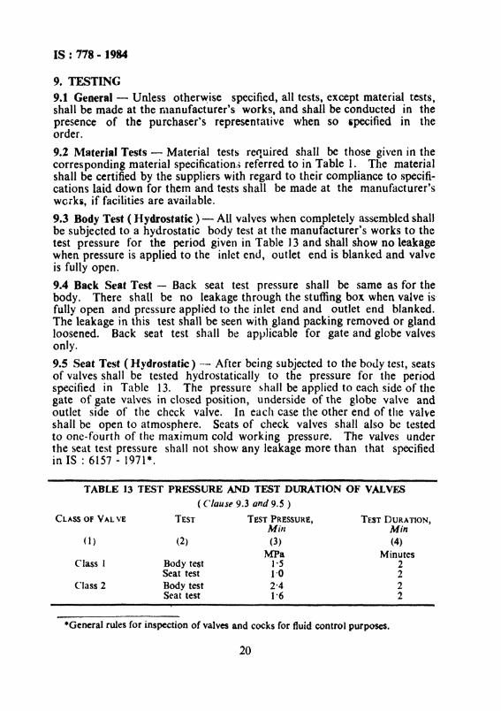
9. TESTING9.1 General - Unless otherwise specified, all tests, except material tests,shall be made at the manufacturer's works, and shall be conducted in thepresence of the purchaser's representative when so specified in theorder.
9.2 Material Tests - Material tests required shall be those given in thecorresponding material specifications referred to in Table 1. The materialshall be certified by the suppliers with regard to their compliance to specifications laid down for them and tests shall be made at the manufacturer'sworks, if facilities are available.
9.3 Body Test ( Hydrostatic) - All valves when completely assembled shallbe subjected to a hydrostatic body test at the manufacturer's works to thetest pressure for the period given in Table) 3 and shall show no leakagewhen pressure is applied to the inlet end, outlet end is blanked and valveis fully open.
9.4 Back Seat Test - Back seat test pressure shall be same as for thebody. There shall be no leakage through the stuffing box when valve is'fully open and pressure applied to the inlet end and outlet end blanked.The leakage in this test shall be seen with gland packing removed or glandloosened. Back seat test shall be applicable for gate and globe valvesonly.
9.5 Seat Test ( Hydrostatic) -- After being subjected to the body test, seatsof valves shall be tested hydrostatically to the pressure for the periodspecified in Table 13. The pressure shall be applied to each side of thegate of gate valves in closed position, underside of the globe valve andoutlet side of the check valve. In each case the other end of the valveshall be open to atmosphere. Seats of check valves shall also be testedto one-fourth of the maximum cold working pressure. The valves underthe seat test pressure shall not show any leakage more than that specifiedin IS : 6157 - 1971 *.
22
TEST DURATION,Min(4)
Minutes22
(2)
Body testSeat testBody testSeat test
TABLE 13 TEST PRESSURE AND TEST DURATION 01.' VALVES
( Clause 9.3 and 9.S )
TEST TEST PRESSURE,Mill(3)
MPaI·S1'02'41·6
(1)
Class I
CLASS OF VAL VE
·General rules for inspection of valves and cocks for fluid control purposes.
20
IS : 778 - 1984
10. SAMPLING
10.1 The sampling procedure to be adopted and the criteria for conformityshall be as given in Appendix B.
1t. INSPECTION AND REPAIRS
1J.l Inspection - The inspector representing the purchaser shall have freeaccess at all reasonable urncs to those parts of the manufacturer's workswhich are concerned with the manufacture of valves, and he shall beafforded all reasonable facilities for satisfying himself that the valves arebeing manufactured in accordance with this standard.
J1.1.1 Unless otherwise specified, inspection shall be done at the place ofmanufacturer prior to despatch and shall be conducted so as not to interfere unnecessarily with the operation of the works.
11.1.2 When no inspection is carried out by the purchaser's representative at the manufacturer's works, the manufacturer, when required to d.so, shall provide a certificate stating that the valves conform in all respectsto this standard.
11.1.3 When the purchaser's inspector desires to witness all or parts ofthe specified tests on the components and assembled valves, the manufacturer shall notify the purchaser in advance to enable the inspector to bepresent.
11.2 Repair of Defects - No defects which may appear during manufacture of testing shall be repaired III any way 'Without the consent of thepurchaser.
11.3 Rejection - Completed end assembled valves, rough or finishedcomponents, whether made in the manufacturer's works or purchasedfrom other suppliers if rejected for any cause by the purchaser's inspectorshall not be used in any manner in completing the purchaser's order andshall be removed immediately from the areas of the manufacturer's worksconcerned with the purchaser's order. In case of assembled or partlyassembled 'Valves, this shall not be constructed as preventing the manufacturer from salvaging-sound components from rejected assemblies forreassembly with otl-er components to form complete new valves.
11.4 Valves from stock may be tested hydrostatically without removal ofpaint.
12. PREPARATION
12.1 After inspection and before despatch, valves shall be thoroughly driedand cleaned, after which the wedge gate or disc shall be fully closed.
21
IS : 778 - ]984
The painting of the finished valves shall be at the option of the manufacturer, unless otherwise specified by the purchaser, When painted, Class1 valves shall be painted in blue colour and Class 2 valves in red colour.
12.2 Valves shall be prepared for despatch in such a way as to minimizethe possibility of damage to inside or outside parts during storage or intransit. Openings shall be closed by suitable means to exclude dirt andother foreign matter from the interior of the valves.
12.3 Valves shall be in the closed position when despatched,
12.4 Handwheels of valves above 50 mm size may be removed from thevalves and packed along with the valve secured by cord or wire.
13. MARKING
13.1 Valves shall be marked with the following particulars which shallbe either cast in or stamped on the body and shall be clearly visible.
a) Manufacturer's name or trade ..mark.b) Class number,c) Nominal size, andd) An arrow showing the direction of flow in case of globe valves and
check valves.
13.2 Any additional marking required may be as agreed to between thepurchaser and the manufacturer.13.3 DIS Certification Marking
The product may also be marked with Standard Mark.
13~3.1 The use of the Standard Mark is governed by the provisions of Bureau ofIndian Standards Act, 1986 and tbe Rules and Regulations made thereunder.The details of conditions under which tbe licence for the use of Standard Markmay be granted to manufacturers or producers may be obtained from the Bureauof Indian Standards.
APPENDIX A(C/{IUSe 0.5)
INFOR~IATIONTO BE SUPPLIED wrrn ANENQUIRY OR ORDER
A-I. INFORMATION ON VALVES
A-I.I Certain clauses of this standard permit alternative. It is recommended
IS : 778 - 1984
that the following information be given by the purchaser who issues anenquiry or order for valves conforming to this standard.
a) Type of valve required that is whether gate, globe, angle or check( horizontal" vertical, angle or swing) valve, and also whetherintegral seat or renewable seat, inside screw or outside screw, risingstem or non-rising stem;
b) Class of valve;c) Type of end connections, that is, screwed or flanged;d) Whether flanged end valves are required drilled or undrilled;e) If tests additional to those specified under 9 are required, specify
the requirements; andf) State if inspection of valves required to be done by the purchaser or
his representative.
APPENDIX B(Clause 10.1)
SAMPLING AND CRITERIA FOR CONFORMITY
A-I. SCALE OF SAMPLING
A-l.1 Lot - In any consignment, all the valves made of the same material,of the same nominal size, of the same type and class and from the samebatch of manufacture shall be grouped together to constitute a lot.
A-t.2 For ascertaining the conformity of material in the lot to the requirements of this specification, samples shall be tested from each lot separately.
A-J.3 The number of valves to be selected from the lot shall depend onthe size of the lot and shall be according to Table 14.
SUB-SAMPLESIZS
(4)3S8
132032
TABLE 14 SCALE OF SAMPLING AND CRITERIA FOR CONFORMITY
(Clauses A-1.3. A-2.1.1 and A-2.2 )
SAMPLE ACCEPTANCESIZE NUMBER
(2) (3)8 0
13 020 J32 2SO 380 S
No. Of VALVESIN THB LOT
(I)Up to 150lSI to 300301 to 500SOl to 1 000
1 001 to 3 0003 001 and above
23
IS : 778 - 1984
A-I.3.t These valves shall be selected at random from the lot. In orderto ensure the randomness of selection, procedures given in IS : 4905..1968·may be followed.
A-2. NUMBER OF TESTS AND CRITERIA FOR CONFORMITY
A-2.I All the valves selected according to A-l.3 shall be examined formaterial, design and manufacture and dimensions. A sample valve failingto satisfy one or more of these requirements shall be considered as defective
A-2.t.1 The Jot shall be considered to have satisfied these requirementsif the number of defective valves found in the sample is less than or equalto the corresponding acceptance number given in col 3 of Table 14.
A-2.2 The lot having been found satisfactory according to A...2.1 shall befurther tested for body test, back seat test ( wherever applicable) andseat test. For this purpose, a sub-sample of valves as given in col 4 ofTable 14 shall be taken and subjected to these tests. The number ofvalves required in the sub-sample may be taken from those already testedand found satisfactory according to A-2.1.
A-2.l.! The lot shall be considered to have satisfied the requirements forthese tests if none of valves in the sub-sample fails in any of these tests.
·Methods for random sampling.
24
IS : 778 - 1984
( Continued from page 2 )
Members
SHIH B. R. N. GUPTA
Representing
Engineer-in-Chief's Branch, Army Headquaters,New Delhi
SHRI K. V. KRISHNAMURTHY ( Alternate)SHRI M. K. JAIN Hind Trading & Manufacturing Co Ltd, New
Delhi
SHRI R. K. TANDONSHfH T. N. UBOVPJA
SHRI K. K. JAIN ( Alternate )SHRt S. R. KSKIRSAOAR
SHRI D. K. SEHGALSHRI B. B. SIKKA ( Alternate)
SHRI R. P. SIKKA Sant Brass Metal Works, JalandharSHRI K. SUNIL KUMAR ( Alternate)
SHIH R. K. SOMANY Hindustan Sanitarywarc & Industries Ltd,Bahadurgarh
Ministry of RailwaysDirectorate General of Supplies & Disposals,
New Delhi
National Environmental Engineering ResearchInstitute ( CSIR ). Nagpur
SHRI A. W. DESHPANDE ( Alternate)SHRI G. A. LUHAR Bombay Metal and Alloy Manufacturing Co Pvt
Ltd, BombayLeader Engineering Works, Jalandhar
25
BUREAU OF INDIAN STANDARDS
Headquarters:ManakShavan, 9 Bahadur ShahZafarMarg,NEW DELHI 110002Telephones: 323 0131, 323 3375, 323 9402Fax: 91 11 3234062,91 11 3239399,91 11 3239382
32376 17
3378662
603843
23523 15
8329295
Telegrams : Manaksanstha(Common to all Offices)
Telephone
8-77 0032
Central Laboratory:
Plot No.20/9,Site IV, Sahibabad Industrial Area, Sahibabad 201010
Regional Offlc••:
Central: Manak Bhavan, 9 Bahadur ShahZafarMarg, NEW DELHI 110002
-Eastern: 1/14CIT Scheme VIIM,V.I.P. Road, Maniktola, CALCUTIA700054
Northern: SCQ335-336, Sector34-A, CHANDIGARH 160022
Southern: C.I.T. Campus, IV Cross Road, CHENNAI 600113
tWestern : Manakalaya, E9,Behind MarolTelephone Exchange, Andheri (East),MUMBAI4ooo93
Branch Offices:
'Pushpak', Nurmohamed Shaikh Marg, Khanpur, AHMEDABAD 380001
*Peenya Industrial Area, 1st Stage, Bangalore-Tumkur Road,BANGALORE 560058
Gan99tri Complex, 5th Floor, Bhadbhada Road, T.T. Nagar, BHOPAL 462003
Plot No.62-63, UnitVI, GangaNagar, BHUBANESHWAR 751001
KaJeikathir Buildings, 670 Avinashi Road, COIMBATORE 641037
Prot No.43, Sector16 A, Mathura Road, FARIDABAD 121001
SavitriComplex, 116G.T. Road, GHAZIABAD 201001
53/5WardNo.29, R.G. BaruaRoad, 5th By-lane, GUWAHATI 781003
S-8-S6C, L.N.GuptaMarg, Nampally Station Road, HYDERABAD 500001
E-52,Chltaranjan Marg,C·Scheme, JAIPUR 302001
117/418.8, Sarvodaya Nagar, KANPUR 208005
Seth Shawan, 2nd Floor, Behind LeelaCinema, Naval Kishore Road,(UCKNOW 226001
NIT Building, Second Floor, Gokulpat Market, NAGPUR440010
PatJiputra Industrial Estate, PATNA 800013
Institution of Engineer. (India) Building 1332Shivaji Nagar, PUNE411005
T.C. No. 1411421, University P.O. Palayam, THIRUVANANTHAPURAM 695034
550 1348
8394955
554021
403827
21 01 41
8-288801
8-711996
5411 37
201083
372925
.21 6876
238923
52517t
262305
323835
621 17
~ales Office is at 5 Chowringhee Approach, ~Q. PrincepStreet,CALCUTTA 700072
t SalesOffice is at Novelty Chambers, GrantRoad, MUMBAI 400007*SalesOffice is at •F' Block, Unity Building, Naruhimaraja Square.BANGALORE 56000'.
27 1085
3096528
22239 71
Printed a' Simco Printing Pr..., Deihl
![Index [] · 2010. 4. 30. · Copper Alloy Mechanical Connectors CD_BB Line Mechanical terminals One U-bolt type terminals for copper conductors. Copper alloy terminals with round](https://img.pdfslide.us/doc/110x75/5fe21e440f47565e460947a6/index-2010-4-30-copper-alloy-mechanical-connectors-cdbb-line-mechanical.jpg)