Embed Size (px)
Citation preview
Disclosure to Promote the Right To Information
Whereas the Parliament of India has set out to provide a practical regime of right to information for citizens to secure access to information under the control of public authorities, in order to promote transparency and accountability in the working of every public authority, and whereas the attached publication of the Bureau of Indian Standards is of particular interest to the public, particularly disadvantaged communities and those engaged in the pursuit of education and knowledge, the attached public safety standard is made available to promote the timely dissemination of this information in an accurate manner to the public.
इंटरनेट मानक
“!ान $ एक न' भारत का +नम-ण”Satyanarayan Gangaram Pitroda
“Invent a New India Using Knowledge”
“प0रा1 को छोड न' 5 तरफ”Jawaharlal Nehru
“Step Out From the Old to the New”
“जान1 का अ+धकार, जी1 का अ+धकार”Mazdoor Kisan Shakti Sangathan
“The Right to Information, The Right to Live”
“!ान एक ऐसा खजाना > जो कभी च0राया नहB जा सकता है”Bhartṛhari—Nītiśatakam
“Knowledge is such a treasure which cannot be stolen”
“Invent a New India Using Knowledge”
है”ह”ह
IS 7513 (1974): Graphical symbols for fluid power systems[PGD 16: Fluid Power]

UDC 621.6 : 744.4 : 003.62 j Second Reprint OCTOBER 1997 ) IS : 751391974
Indian Standard
GRAPHICAL SYMBOLS FOR
FLUID POWER SYSTEMS
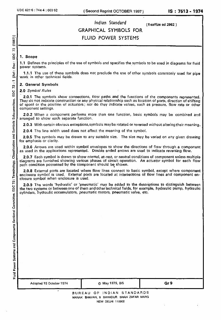
1. Scope
1 .l Defines the principles of the use of symbols and specifies the symbols to be used in diagrams for fluid power systems.
1 .I .I The use of these symbols does not preclude the use of other symbols commonly used for pipe work in other technical fields.
2. General Symbols
2.0 Symbol Rules
2.0.1 The symbols show connections, flow paths and the functions of the components represented. They do not indicate construction or any physical relationship such as location of ports, direction of shifting of spool or the position of actuators; nor do they indicate values, such as pressure, flow rate or other component settings.
2.0.2 When a component performs more than one function, basic symbols may be combined and arranged to show each separate function.
2.0.3 With certain obvious exceptions,symbols may be rotated or reversed without altering their meaning.
2.0.4 The line width used does not affect the meaning of the symbol.
2.0.5 The symbols may be drawn to any suitable size. The size may be varied on any given drawing for emphasis or clarity.
2.0.6 Arrows are used within symbol envelopes to show the directions of flow through a component as used in the applications represented. Double ended arrows are used to indicate reversing flow.
2.0.7 Each symbol is drawn to show normal, at-rest, or neutral conditions of component unless multiple diagrams are furnished showing various phases of circuit operation. An actuator symbol for each flow path condition possessed by the component should b$ shown.
2.0.8 External ports are located where flow lines connect to basic symbol, except where component enclosure symbol is used. External ports 8re located at intersections of flow lines and component en- closure symbol when.enclosure is used.
2.09 The words ‘hydraulic’ or ‘pneumatic’ may be added to the descriptions to distinguish between the two systems or between one of them and other technical fields, for example, hydraulic ~pump, hydraulic cylinders, hydraulic accumulators, pneumatic motors, pneumatic valve, etc.
Adopted 15 October 1974 I
0 May 1975, BIS I
Gr9
BUREAU OF INDIAN STANDARDS
MANAK BHAVAN, 9 BAHADUR SHAH ZAFAR MARG
NEW DELHI 110002
IS : 7513 - 1974
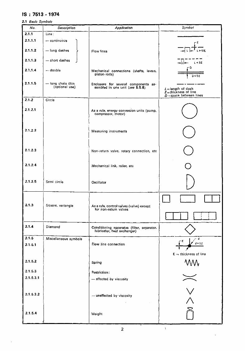
2.1 Basic Svmbols
No. I
.l.l
.l.l.l
.1.1.2
.1.1.3
.1.1.4
.1.1.5
.I.2
!.I.21
!.1.2.2
!.1.2.3
!.1;2.4
!.1.2.5
Al.3
2.1.4
2.1.5
2.1.5.1
2.1.5.2
2.1.5.3
2.1.5.3.1
2.1.5.3.2
2.1.5.4
Line :
- continuous 7
- long dashes
I - short dashes J
- double
- long chain thin (optional use)
Enclosure for several components as- sembled in one unit (see 5.5.8)
Circle
,- I
- ,
-
-
-
I
Semi circle
Square, rectangle
Diamond
Miscellaneous symbols
Application
ilow lines
Mechanical connections (shafts, levers, piston-rods)
As a rule, energy conversion units (pump, compressor, motor)
Measuring instruments
Non-return valve, rotary connection, etc
Mechanical link, roller, etc
Oscillator
As a rule, control valves (valve) except for non-return valves
Conditioning apparatus (filter, separator, lubricator, heat exchanger)
Flow line connection
Spring
Restriction :
- affected by viscosity
.-_ unaffected by viscosity
Weight
Symbol
J-Jr -I_,,‘;
,=+k= -----
L=length of dash E=thickness of line D=space between lines
-
0 0 0 0
D q IEIU
0 ,&LiE fE
E = thickness of line
v A
ITi 2
IS : 7513 - 1974
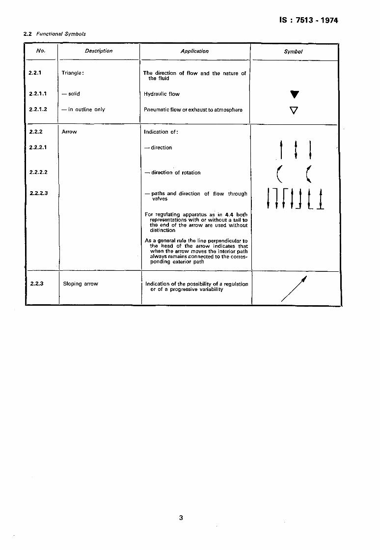
2.2 Functional Symbols
No. Description Application Symbol
2.2.1 Triangle : The direction of flow and the nature of the fluid
2.2.1 .I - solid Hydraulic flow V
2.2.1.2 - in outline only Pneumatic flow or exhaust to atmosphere V
2.2.2 Arrow Indication of:
2.2.2.1 - direction
I t I
2.2.2.2 -direction of rotation
( C
2.2.2.3 - ya;!;sand direction of flow through
llrlf t1
For regulating apparatus as in 4.4 both representations with or without a tail to the end of the arrow are used without -distinction
As a general rule the line perpendicular to the head of the arrow indicates that when the arrow moves the interior path always remains connected to the corres- ponding exterior path
2.2.3 Sloping arrow I
Indication of the possibility of a regulation or of a progressive variability
/
3
IS : 7513 - 1974
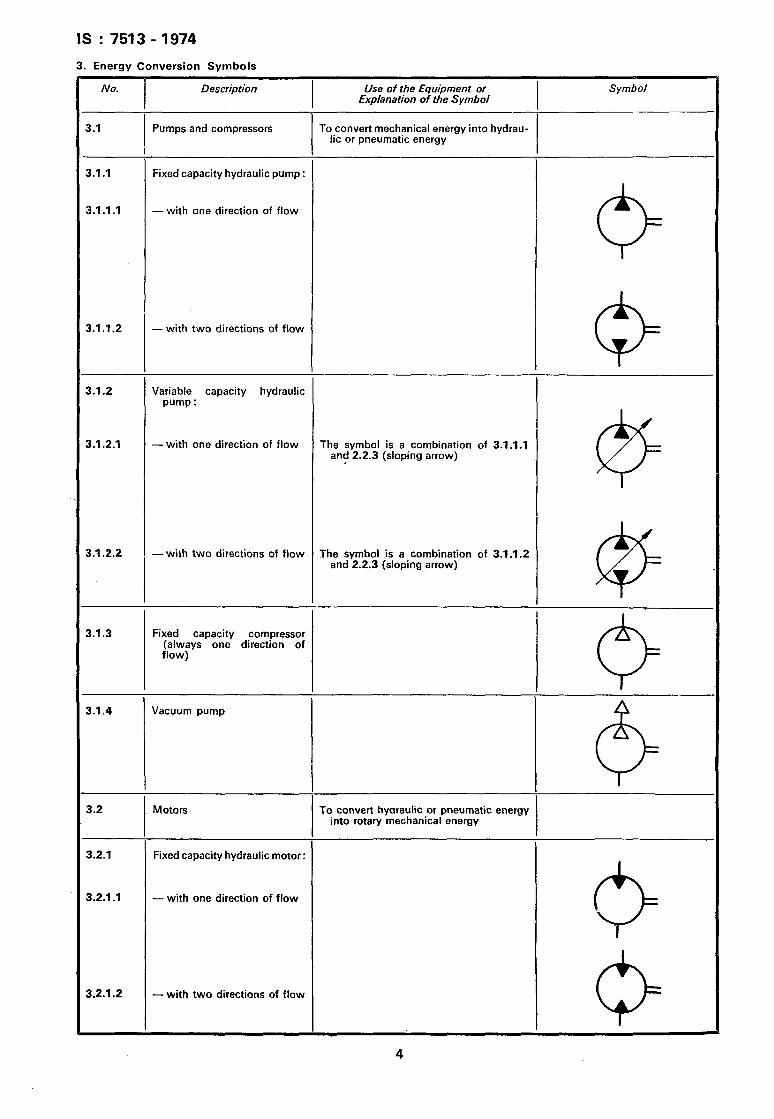
3. Energy Conversion Svmbols
No.
3.1
Description
Pumps and compressors
Use of the Equipment or Explanation of the Symbol
To convert mechanical energy into hydrau- lic or pneumatic energy
Symbol
3.1 .I Fixed capacity hydraulic pump :
3.1.1.1 - with one direction of flow
0
3.1.1.2 - with two directions of flow
0 -~
3.1.2 Variable capacity hydraulic pump :
3.1.2.1 - with one direction of flow The symbol is a combination of 3.1 .l.l and 2.2.3 (sloping arrow)
@
3.1.2.2 - with two directions of flow The symbol is a combination of 3.1.1.2 and 2.2.3 (sloping arrow)
@
3.1.3 Fixed capacity compressor (always one direction of flow)
8 --
3.1.4 Vacuum pump
I 6-
3.2 Motors To convert hyaraulic or pneumatic energy into rotary mechanical energy
I
3.2.1 Fixed capacity hydraulic motor:
3.2.1.1 - with one direction of flow
(3
3.2.1.2 - with two directions of flow
IS : 7513 - 1974
No. Description Use of the Equipment or Explanation of the Symbol
Symbol
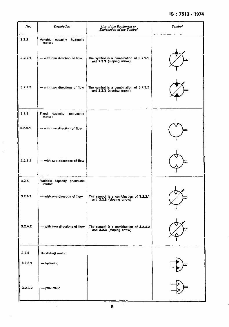
B.2.2 Variable capacity hydraulic motor:
3.2.2.1 -with one direction of flow The symbol is a combination of 3.2.1.1 and 2.2.3 (sloping arrow)
@
3.2.2.2 - with two directions of flow The symbol is a combination of 3.2.1.2 and 2.2.3 (sloping arrow)
@
3.2.3 Fixed capacity pneumatic motor :
1.2.3.1 - with one direction of flow
6
3.2.3.2 - with two directions of flow
3.2.4 Variable capacity pneumatic motor:
Q
3.2.4.1 - with one direction of flow The symbol is a combination of 3.2.3.1 and 2.2.3 (sloping arrow)
@
3.2.4.2 -with two directions of flow The symbol is a combination of 3.2.3.2 and 2.2.3 (sloping arrow)
@
3.2.5 Oscillating motor:
3.2.5.1 - hydraulic
9=
3.2.5.2 - pneumatic
IS : 7513-1974
No. Description Use of the Equipment or Symbol Explanation of the Symbol
_-
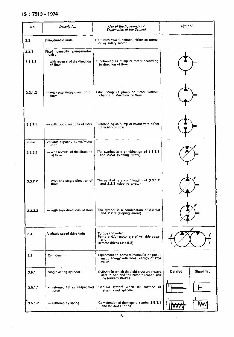
.3 Pump/motor units Unit with two functions, either as pump or as rotary motor
.3.1 Fixed capacity pump/motor unit:
.3.1.1 - with reversal of the direction Functioning as pump or motor according of flow to direction of flow
0
1.3.1.2 -with one single direction of Functioning as pump or motor without flow change of direction of flow
0
1.3.1.3 - with two directions of flow Functioning as pump or motor with either direction of flow
0
3.3.2 Variable capacity pump/motor unit:
3.3.2.1 - with reversal~of the direction The symbol is a combination of 3.3.1.1 of flow and 2.2.3 (sloping marrow)
@
3.3.2.2 -with one single direction of The symbol is a combination of 3.3.1.2 flow and 22.3 (sloping arrqw)
@
3.3.2.3 - with two directions of flow The symbol is a combination ~of 3.3.1.3 and 2.2.3 (sloping arrow)
3.4 Variable speed drive units Torque converter Pump and/or motor are of variable capa-
Re?%e drives (see 9.2)
3.5 Cylinders Equipment to convert hydraulic or pneu- matic energy into linear energy or vice versa
3.5.1 Single acting cylinder: Cylinder in which the fluid pressure always acts in one and the same direction (on the forward stroke)
Detailed Simplified
3.5.1 .I -returned by an unspecified General symbol when the method of force return is not specified II&-=
3.5.1.2 - returned by spring Combination of the general symbol 3.5.1 .I and 2.1.5.2 (Spring)
6
IS : 7513-1974
NO. Description -Use of the Equipment or Explanation of the Symbol
Symbo!
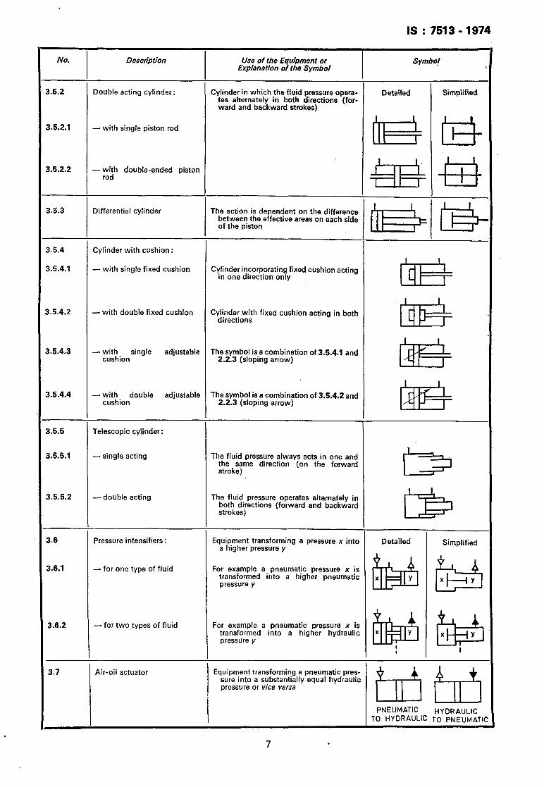
3.5.2 Double acting cylinder: Cylinder in which the fluid pressure opera- tes alternately in both directions (for- ward and backward strokes)
Detailed Simplified
3.5.2.1 - with single piston rod
0&u
3.5.2.2 - with double-ended piston rod
&llz!+I
3.5.3 Differential cylinder The action is dependent on the difference between the effective areas on each side of the piston LB@+
3.5.4 Cylinder with cushion :
3.5.4.1 - with single fixed cushion Cylinder incorporating fixed cushion acting in one direction only
LB-
3.5.4.2 - with double fixed cushion Cylinder with fixed cushion acting in both directions
L&?=
3.5.4.3 - with single adjustable The symbol is a combination of 3.5.4.1 and cushion 2.2.3 (sloping arrow)
LB-
3.5.4.4
3.5.5
3.5.5.1
3.5.5.2
-with double adjustable The symbol is a combination of 3.5.4.2 and cushion 2.2.3 (sloping arrow)
@I@=
Telescopic cylinder:
-single acting The fluid pressure always acts in .one and the same direction (on the forward stroke) LIB
- double acting The fluid pressure operates alternately in both directions (forward and backward strokes) LB
3.6 Pressure intensifiers : Equipment transforming a pressure x into a higher pressure y
Detailed Simplified
3.6.1 -for one type of fluid For example a pneumatic pressure x is transformed into a higher pneumatic pressure y & H
3.6.2 -for two types of fluid For example a pneumatic pressure x is transformed into a higher hydraulic pressure y
i!J$$$$ &3
I I
3.7 Air-oil actuator Equipment transforming a pneumatic pres- sure into a substantially equal hydraulic pressure or vice vefsa
titi
PNEUMATIC HYDRAULIC TO HYDRAULlC TO PNEIJMATK
4. Control Valve Symbols
No. I Description Use of the Equipment or Symbol Explanation of the Symbol
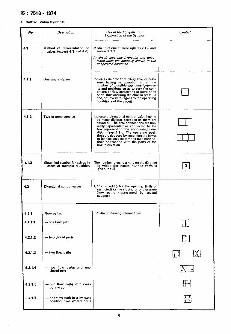
.I Method of representation of Made up of one or more squares 2.1.3 and valves (except 4.3 and 4.6) arrows 2.2.2
In circuit diagrams hydraulic and pneu- matic units are normally shown in the unoperated condition
..I .l One single square Indicates unit for controlling flow or pres- sure, having in operation an infinite number of possible positions between its end positions so as to vary the con- ditions of flow across one or more of its ports, thus ensuring the chosen pressure and/or flow with regard to the operating conditions of the circuit
cl
1.1.2 Two or more squares indicate a directional control valve having as many distinct positions as there are squares. The pipe connections are nor- mally represented as connected to the box representing the unoperated con- dition (see 4.1). The operating posi- tionsare deduced by imagining the boxes to be displaced so that the pipe connec- tions correspond with the ports of the box in question
,.I .3 Simplified symbol for valves in cases of multiple repetition
The number refers to a note on the diagram in which the symbol for the valve is
0
3 given in full
1.2 Directional control valves Units providing for the opening (fully or restricted) or the closing of one or more z;zrap;ths (represented by several
1.2.1 Flow paths : Square containing interior lines
4.2.1 .I - one flow path
.- Kl
4.2.1.2 -two closed ports El
4.2.1.3 -two flow paths Lul lxl
4.2.1.4 -two flow paths and one closed port IXI
4.2.1.5 -two flow paths with cross connection El
4.2.1.6 - one flow path in a by-pass position, two closed ports Q
8
IS : 7513 -1974
-
4.
4.
4.
4.
-
4
4
4
4
4
4
4
1
,
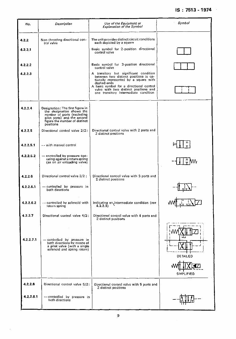
Non-throttling directional con- The unit provides distinct circuit conditions trol valve each depicted by a square
Basic symbol for P-position directional control valve III
2.2.2
2.2.3
Basic symbol for 3-position directional control valve I I I I
A transitory but significant condition between two distinct positions is op- tionally represented by a square with dashed ends
NO. Description Use of the Equipment or Explanation of the Symbol
Symbol
2.2
2.2.1
A basic symbol for a directional control valve with two distinct positions and one transitory intermediate condition I
.2.2.4
.2.2.5
Designation : The first figure in the designation shows the number of ports (excluding pilot ports) and the second figure the number of distinct positions
Directional control valve 2/2 : Directional control valve with 2 ports and 2 distinct positions
.2.2.5.1 - with manual control Cl
.2.2.5.2 - controlled by pressure ope- rating against a return spring (as on air unloading valve) -ill3un
1.2.2.6 Directional control valve 3/2 : Directional control valve with 3 ports and 2 distinct positions
1.2.2.6.1 - controlled by pressure in both directions -QQ-
1.2.2.6.2 - controlled by solenoid with return spring
Inc&at2nr) andntermediate condition (see . . .
1.2.2.7 Directional control valve 4/2: Directional control valve with 4 ports and 2 distinct positions
__-____ f----i r---,l
r&$y,, fia I f I j
I I
4.2.2.7.1 - controlled by pressure in I P I
both directions by means of I 1 I ’
a pilot valve (with a single I I-- -J
solenoid and spring return) L-q- _ J
DETAILED
SIMPLIFIED
4.2.2.8 Directional control valve 5/2 : Directional control valve with 5 ports and 2 distinct positions
4.2.2.8.1 - controlled by pressure in both directions
-
IS : 7513 - 1974
No.
4.2.3
Description Use bf the Equipment or Symbol Explanation of the Symbol
--
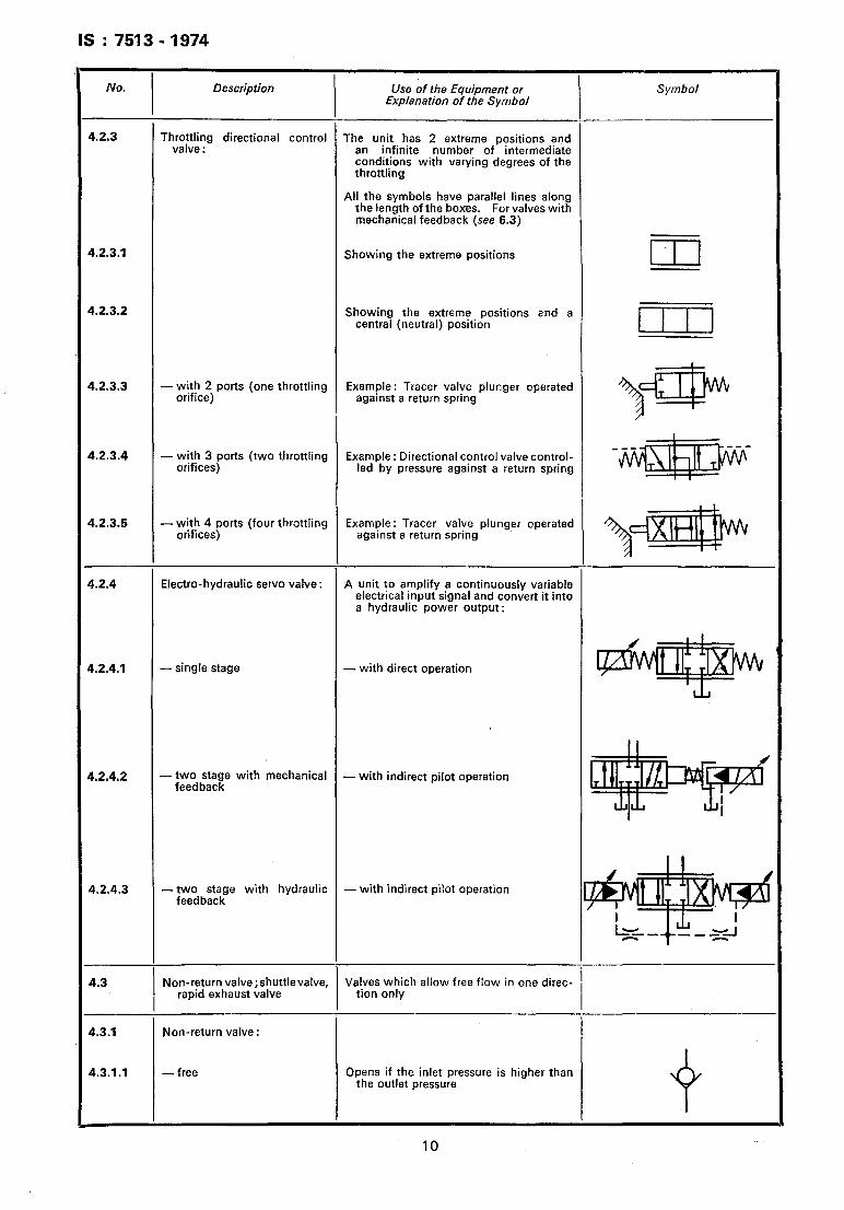
Th;$$g directional control The unit has 2 extreme positions and an infinite number of intermediate conditions with varying degrees of the throttling
All the symbols have parallel lines along the length of the boxes. For valves with mechanical feedback (see 6.3)
4.2.3.1 Showing the extreme positions I
4.2.3.2 Showing the extreme positions and a central (neutral) position I I I 1
I 4.2.3.3 - with 2 ports (one throttling
orifice) Example : Tracer valve plunger operated
against a return spring
?? ‘P
4.2.3.4 - with 3 ports (two throttling orifices)
Example: Directional control valve control- led by pressure against a return spring
I I
4.2.3.5 - with 4 ports (four throttling orifices)
Example : Tracer valve plunger operated against a return spring
\*‘H’i p
4.2.4 Electra-hydraulic servo valve : A unit to amplify a continuously variable electrical input signal and convert it into a hydraulic power output:
4.2.4.1 - single stage - with direct operation
4.2.4.2 -two stage with mechanical - feedback
with indirect pilot operation
4.2.4.3 -two stage with hydraulic - with indirect pilot operation feedback
4.3
4.3.1
4.3.1 .I
, Non-return valve;shuttlevalve, Valves which allow free flow in one direc-
rapid exhaust valve tion only
Non-return valve:
-free Opens if the inlet pressure is higher than the outlet pressure
10
IS : 7513 - 1974
No. Description Use of the Equipment or Explanation of the Symbol
Symbol
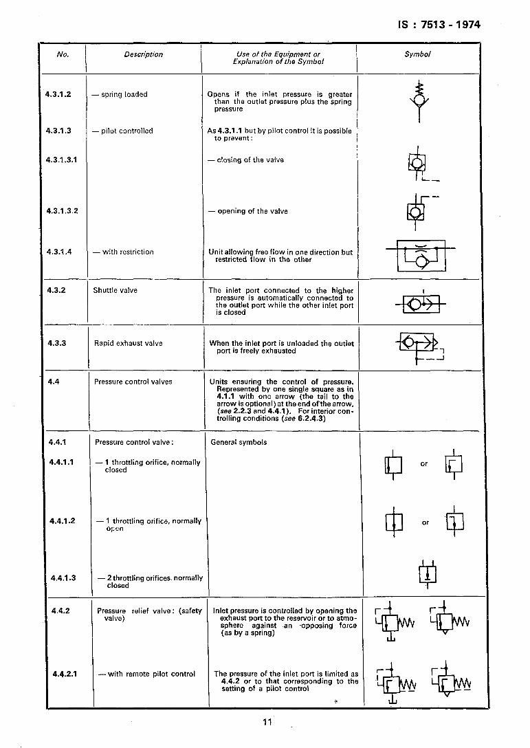
3.1.2 - spring loaded Opens if the inlet pressure is greater than the outlet pressure plus the spring pressure
3.1.3 - pilot controlled As 4.3.1 .I but by pilot control it is possible to prevent:
- closing of the valve
3.1.3.2 - opening of the valve
.3.1.4 - with restriction Unit allowing free flow in one direction but restricted flow in the other
83.2 Shuttle valve The inlet port connected to the higher pressure is automatically connected to the outlet port while the other inlet port is closed -EC&-
.3.3 Rapid exhaust valve When the inlet port is unloaded the outlet port is freely exhausted
Pressure control valves Units ensuring the control of pressure. Represented by one single square as in 4.1.1 with one arrow (the tail to the arrow is optional) at the end ofthe arrow, (see 2.2.3 and 4.4.1). For interior con- trolling conditions (see 6.2.4.3)
,.4.1
1.4.1 .I
Pressure control valve : General symbols
- ltlt~ttling orifice, normally
1.4.1.2 - 1 throttling orifice, normally open
5.4.1.3
4.4.2
- 2$rsr;tling orifices. normally
Pmssess;; relief valve: (safety Inlet pressure is controlled by opening the exhaust port to the reservoir or to atmo- sphere against an ~opposing force (as by a spring)
4.4.2.1 - with remote pilot control The pressure of the inlet port is limited as 4.4.2 or to that corresponding to the setting of a pilot control
IS : 7513 -1974
No. Description Use of the Equipment or Explanation of the Symbol
I Symbol
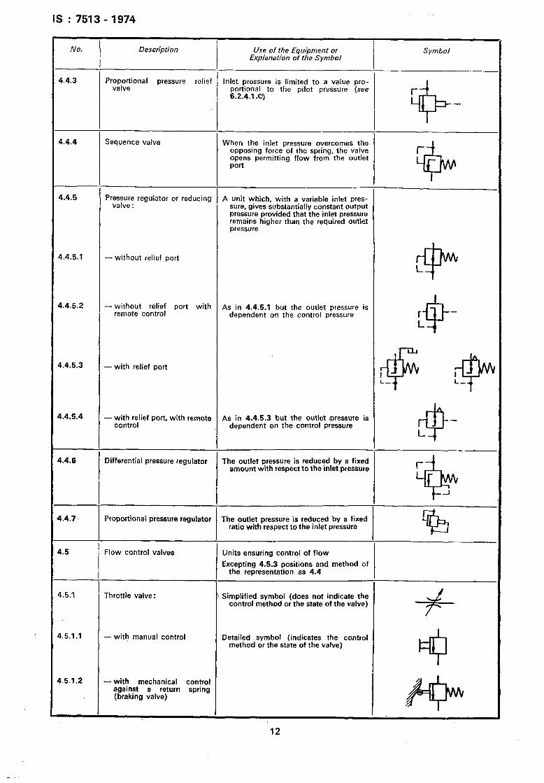
4.4.3 Proportional pressure relief valve
Inlet pressure is limited to a value pro- portional to the pilot pressure (see 6.2.4.1 .C)
4.4.4 Sequence valve When the inlet pressure overcomes the opposing force of the spring, the valve opens permitting flow from the outlet Port
4.4.5 Pressure regulator or reducing valve :
A unit which, with a variable inlet pres- sure, gives substantially constant output pressure provided that the inlet pressure remains higher than the required outlet pressure
4.4.5.1 - without relief port
4.4.5.2 - without relief part with As in 4.4.5.1 but the outlet pressure is remote control dependent on the control pressure
4.4.5.3 -with relief port
&4.5.4 - . ~;;~,bellief port, with remote As in 4.4.5.3 but the outlet ,pressure is dependent on the control pressure
4.4.6 Differential pressure regulator The outlet pressure is reduced by a fixed amount with respect to the inlet pressure
4.4.7 Proportional pressure regulator The outlet pressure is reduced by a fixed ratio with respect to the inlet pressure
4.5 Flow control valves Units ensuring control of flow
Excepting 4.5.3 positions and method of the representation as 4.4
4.5.1 Throttle valve : \ Simplified symbol (does not indicate the control method or the state of the valve)
4.5.1.1 - with manual control Detailed symbol (indicates the control method or the state of the valve)
4.5.1.2 - with mechanical control against a return spring (braking valve)
12
IS : 7513 - 1974
, NO. Description Use of the Equipment or Symbol
Explanation of the Symbol
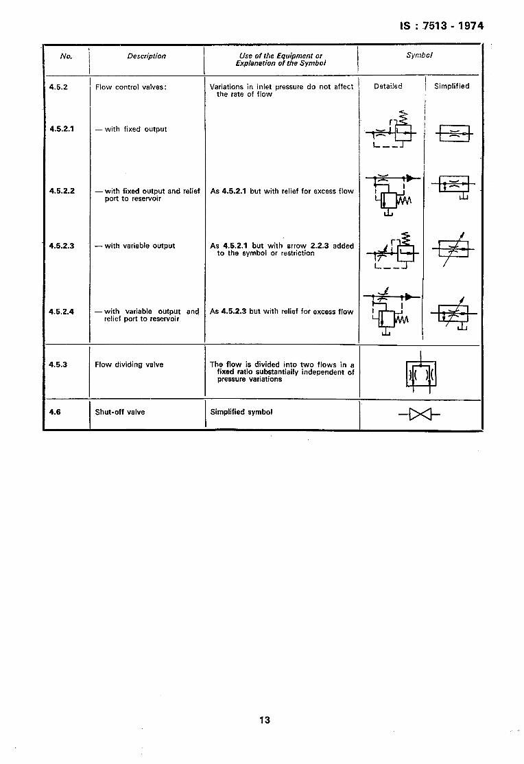
I 4.5.2 ’ Flow control valves: Variations in inlet pressure do not affect Detailed
the rate of flow / Simplified
4.5.2.1 - with fixed output
4.5.2.2 -with fixed output and relief As 4.5.2.1 but with relief for excess flow port to reservoir
4.5.2.3 -with variable output As 4.5.2.1 but with arrow 2.2.3 added to the symbol or restriction
4.5.2.4 - with variable output and As 4.5.2.3 but with relief for excess flow relief port to reservoir
4.5.3 Flow dividing valve The flow is divided into two flows in a fixed ratio substantially independent of pressure variations
4.6
I
Shut-off valve
I
Simplified symbol
13
IS : 7513 - 1974
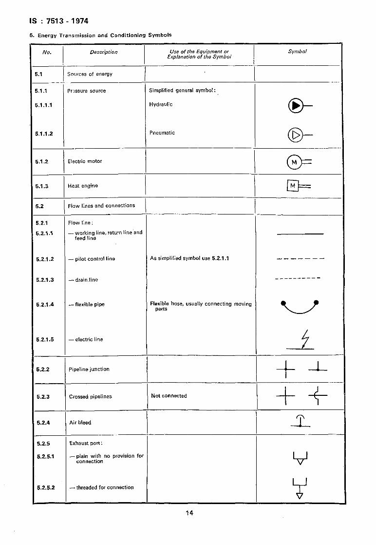
5. Energy Transmission and Conditioning Symbols
No. Description Use of the Equipment or Symbol Explanation of the Symbol
I.1 Sources of energy I I
I.1 .I Pressure source Simplified general symbol:
i.l .I .I Hydraulic
o- b
i.1 .I .2 Pneumatic
o- D
i.l.2 Electric motor
I @=
i.l.3 Heat engine II==
M
i.2 Flow lines and connections
i.2.1 Flow line :
i.2.1.1 - working line, return line and feed line
5.2.1.2 - pilot control line As simplified symbol use 5.2.1 .l _--- ---
j.2.1.3 - drain line ___-------
5.2.1.4 -flexible pipe Flexible hose, ~usually connecting moving parts
5.2.1.5 - electric line
A-
5.2.2 Pipeline junction
+
1
5.2.3 Crossed pipelines Not connected
+f
n 5.2.4 Air bleed
-L_
5.2.5 Exhaust port:
5.2.5.1 - plain with no provision for connection V
5.2.5.2 -threaded for connection
14
IS : 7513 -1974
Description Use of the Equipment or Explanation of the Symbol
Symbol
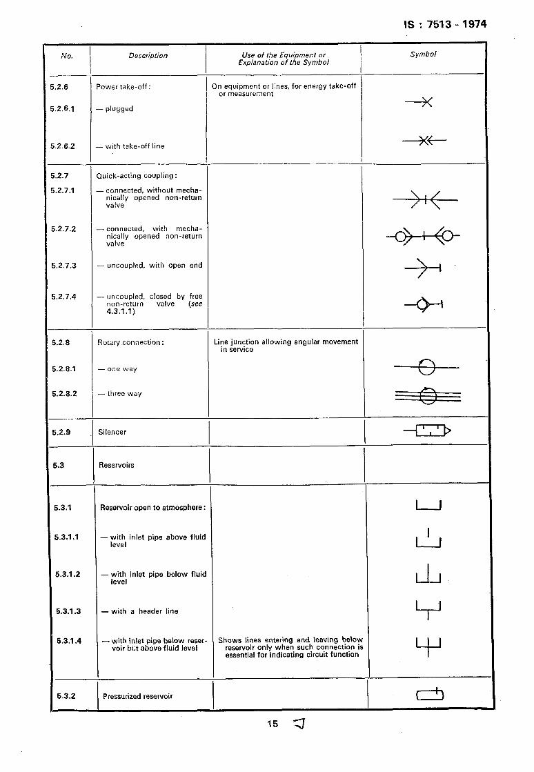
2.6 Power take-off:
2.6.1 - plugged
On equipment or lines, for energy take-aff or measurement
2.6.2 - with take-off line _3(+
2.7 Quick-acting coupling :
2.7.1 - connected, without mecha- nically opened non-return valve
\I/
.2.7.2 - connected, with mecha- nically opened non-return valve
.2.7.3 - uncoupled, with open end
-+-
.2.7.4 - uncoupled, closed by free non-return valve (see 4.3.1.1)
Rotary connection : Line junction allowing angular movement in service
.2.8.1 -one way
.2.8.2 -three way h I \
I U
.2.9
i.3
Silencer
Reservoirs
i.3.1 Reservoir open to atmosphere: I I
5.3.1 .I - ;vi, inlet pipe above fluid L-!-l
5.3.1.2 - with inlet pipe below fluid level LlJ
5.3.1.3 - with a header line V
5.3.1.4 - with inlet pipe below reser- Shows lines entering and leaving below voir but above fluid level reservoir only when such connection is
essential for indicating circuit function Y
* 6.3.2 Pressurized reservoir (
I
IS : 7513 - 7974
No. Description Use of the Equipment or Explanation of the Symbol
Symbol
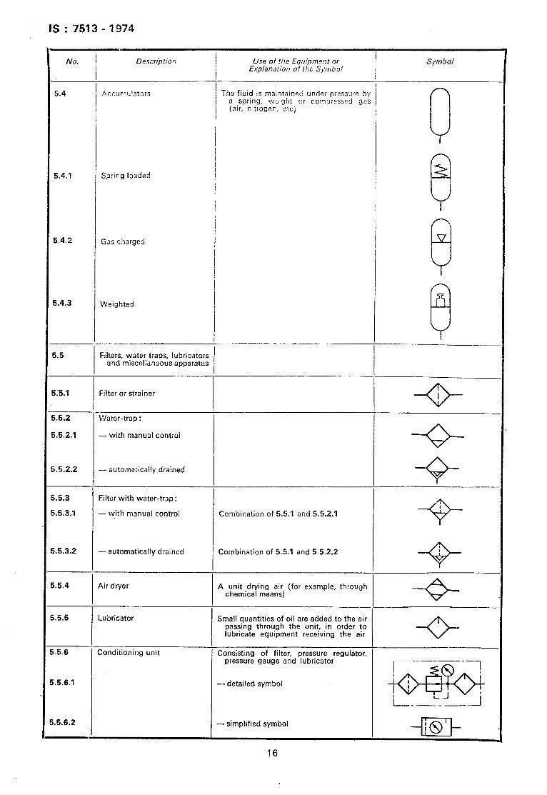
5.4 Accumulators The fluid is maintained under pressure by a spring, weight or compressed gas
(air, nitrogen, etc)
I 1
, 1 / I
5.4.1 Spring loaded
1
; 8
5.4.2 Gas charged
$
5.4.3
i.5
Weighted
Frlters, water traps, lubricators and miscellaneous apparatus
a
ii5.1 Filter or strainer
i.5.2 Water-trap :
;.5.2.1 - with manual control
.5.2.2 - automatkally drained
.5.3 Filter with water-trap :
.5.3.1 - with manual control
.5.3.2 - automatically drained
5.4 Air dryer
5.5 Lubricator
.5.6 Conditionfng unit
-+?-
I Combination of 5.51 and 552.1
+?-
Combination of 5.5.1 and 5.5.2.2 I
+
A unit drying air (for example, through chemical means)
I --+
Small quantities of oil are added to the air passing through the unit, in order to lubricate equipment receiving the air -O-
Consisting of filter, pressure regulator, pressure gauge and lubricator
-5.6.1 - detailed symbol
.5.6.2 - simplified symbol
16
IS : 7513 - 1974
No. Description Use of the Equipment or Explanation of the Symbol
Symbol
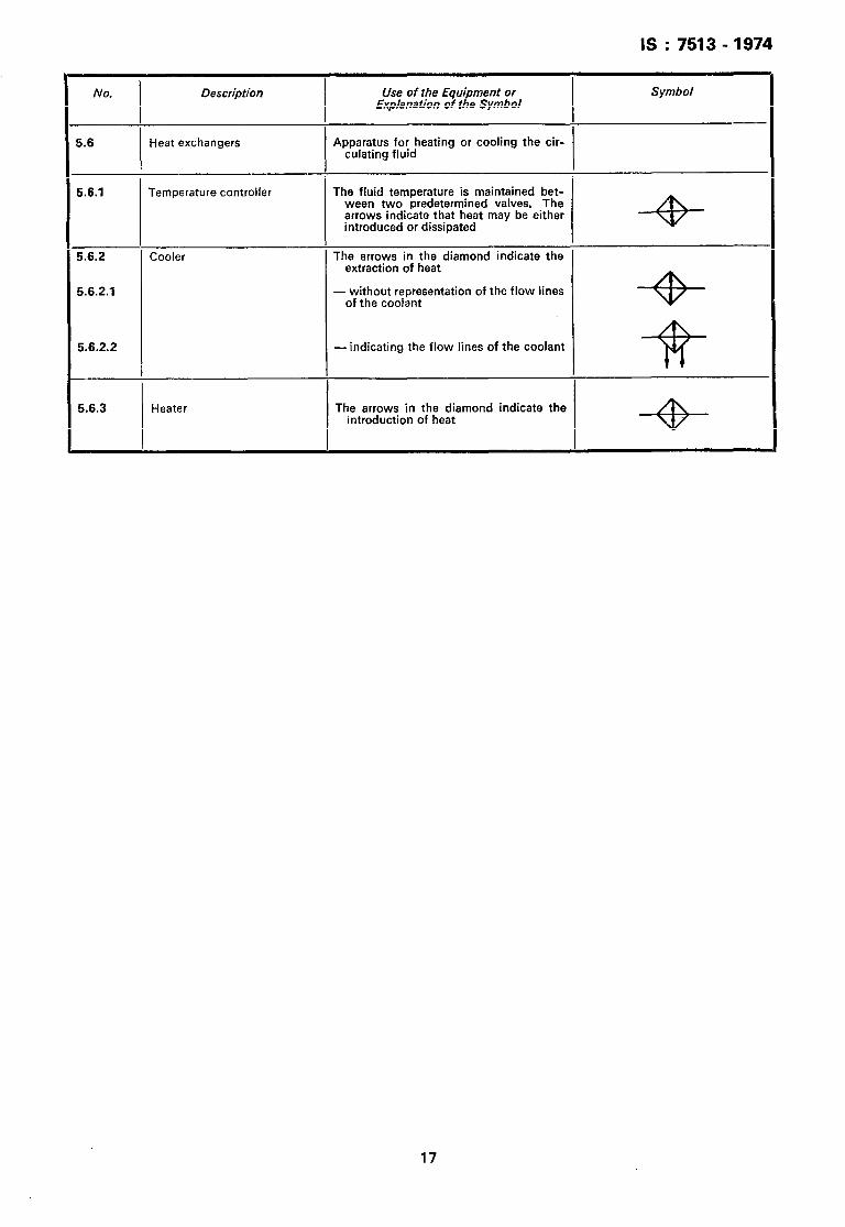
5.6 Heat exchangers Apparatus for heating or cooling the cir- culating fluid
5.6.1 Temperature controller The fluid temperature is maintained bet- ween two predetermined valves. The arrows indicate that heat may be either introduced or dissipated
5.6.2 Cooler The arrows in the diamond indicate the extraction of heat
5.6.2.1 - without representation of the flow lines of the coolant --+
5.6.2.2 - indicating the flow lines of the coolant
5.6.3 Heater The arrows in the diamond indicate the introduction of heat
17
IS : 7513 - 1974
6. Control Mechanism Symbols
No. Description Use of the Equipment or Explanation of the Symbol
Symbol
i.1 I
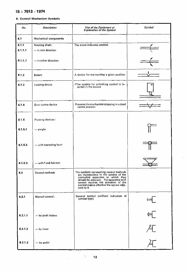
Mechanical components
I I i.1 .I Rotating shaft: The arrow indicates rotation
f I i.l.l.1 - in one direction
\
5.1.1.2 - in either direction f I
\
3.1.2 Detent A device for maintaining a given ~position I
6.1.3
6.1.4
Locking device
Over-centre device
*The symbol for unlocking control is in- serted in the square
Prevents the mechanism stopping in a dead centre position
*
1
\ , \ / V
6.1.5 Pivoting devices:
6.151 - simpte
6.1.5.2 - with traversing lever
“if
6.1.5.3 - with fixed fulcrum
6.2 Control methods The symbols representing control methods are incorporated in the symbol of the controlled apparatus to which they should be adjacent. For apparatus with several squares the actuation of the control makes effective the square adja- cent to it
Sz
6.2.1 Manual control : General symbol (without indication of control type)
6.2.1 .I - by push button @II
6.2.1.2 - by lever K
6.2.1.3 - by pedal
18
IS : 7513 - 1974
NC?. Description Use of the Equipment or Explanation of the Symbol
Symbol
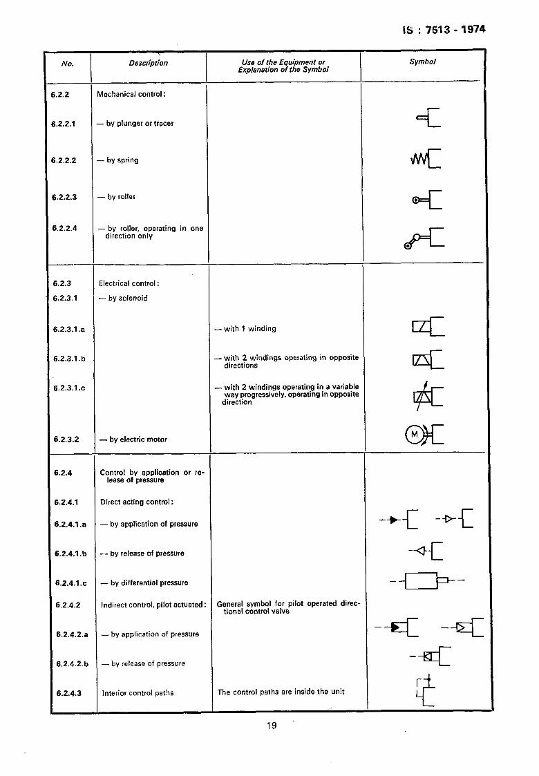
.2.2 Mechanical control:
.2.2.1 - by plunger or tracer +=L
.2.2.2 - by spring m++QIII
.2.2.3 - by roller
Q=K .
.2.2.4 - by roller, operating in one direction only
K .
i.2.3 Electrical control :
L2.3.1 - by solenoid
L2.3.1 .a -with 1 winding c
i.2.3.1 .b - with 2 windings operating in opposite directions +=I
i.2.3.1 .c - with 2 windings operating in a variable way progressively, operating in opposite
direction 6
f.2.3.2 - by electric motor c917
M
i.2.4 Control by application or re- lease of pressure
5.2.4.1 Direct acting control :
5.2.4.1 .a - by application of pressure -+$_ -*_c
3.2.4.1 .b - by release of pressure -*F-
6.2.4.1 .c - by differential pressure -G-
6.2.4.2 Indirect control, pilot actuated : General symbol for pilot operated direc- tional control valve
6.2.4.2.a - by application of pressure -trIz -=K
6.2.4.2. b - by release of pressure -*
6.2.4.3 Interior control paths The control paths are inside the unit
19 -
IS : 7513 - 1974
No. Description Use of the Equipment or Explanation of the Symbol
Symbol
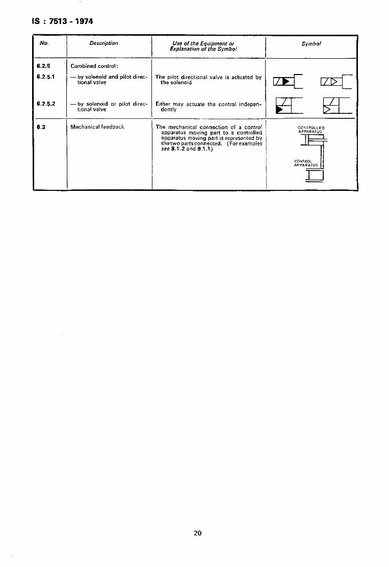
6.2.5 Combined control :
6.2.5.1 -by solenoid and pilot direc- tional valve
The pilot directional valve is actuated by the solenoid
Q4I llDl
6.2.5.2 -by solenoid or pilot direc- tional valve
Either may actuate the control indepen- dentlv 5- HI_
6.3 Mechanical feedback The mechanical connection of a control apparatus moving part to a controlled apparatus moving part is represented by thetwo partsconnected. (For examples 1 see 8.1.2 and 9.1 .I)
CONTROLLED APPARATUS
7
CONTROL APPARATUS
20
IS : 7513 -1974
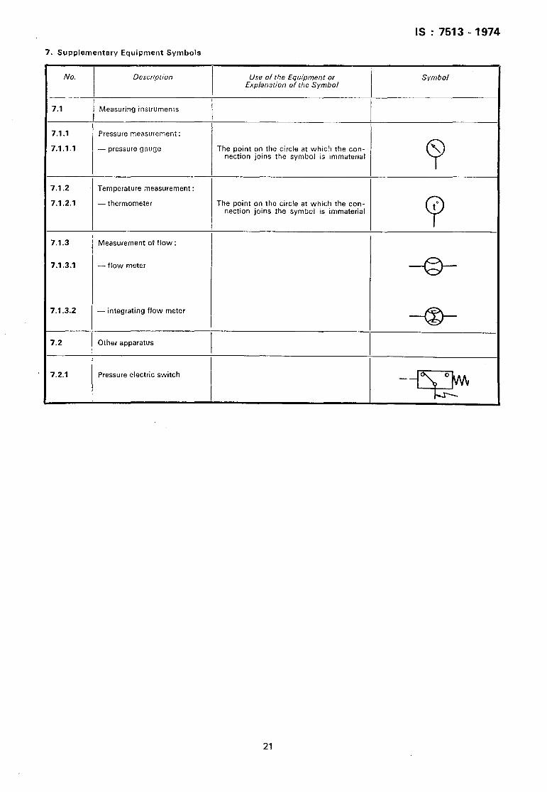
7. Supplementary Equipment Symbols
No. Description Use of the Equipment or Explanation of the Symbol
Symbol
7.1 Measuring instruments
7.1 .I Pressure measurement:
7.1.1.1 -pressure gauge The point on the circle at which the con- nection joins the symbol is immaterial
\
0
7.1.2 Temperature measurement :
7.1.2.1 - thermometer The point on the circle at which the con- nection joins the symbol is immaterial to
P
7.1.3 Measurement of flow :
7.1.3.1 - flow meter
7.1.3.2 - integrating flow meter
7.2 Other apparatus I
7.2.1 Pressure electric switch
21
IS : 7513 -1974
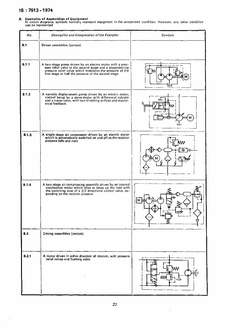
.8. -Examples of Assemblies of Equipment In circuit diagrams, symbols normally represent equipment in the unoperated condition. However, any other condition can be represented
No. Description and Interpretation of the Examples
.I Driven assemblies (pumps)
Symbols
1.1 .l A two-stage pump driven by an ‘electric motor with a pres- sure relief valve in the second stage and a proportioning pressure relief valve which maintains the pressure of the first stage at half the pressure of the second stage
1.1.2 A variable displacement pump driven by an electric motor, control being by a serve-motor with differential cylinder and a tracer valve, with two throttling orifices and mecha- nical feedback
8.4.3 A single-stage air compressor driven by an electric motor which is automatically switched on and off as the receiver pressure falls and rises
3.1.4 A two-stage air compressing assembly driven by an internal combustion motor which idles or takes up the load with
_ - -- ~_ --__
the switching over of a 3/2 directional control valve, de- pending on the receiver pressure
B.2 Driving assemblies (motors)
8.2.1 A motor driven in either direction of rotation, with pressure relief valves and flushing valve
22
No.
B.3
6.3.1
Description and Interpretation of the Examples
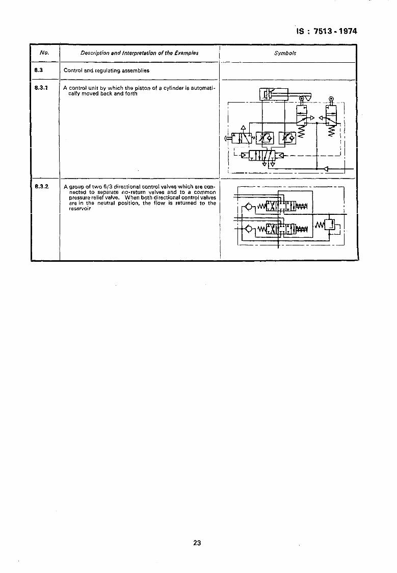
Control and regulating assemblies
A control unit by which the piston of a cylinder is automati- cally moved back and forth
Symbols
8.3.2 A group of two 6/3 directional control valves which are con- nected to separate no-return valves and to a common pressure relief valve. When both directional control valves are in the neutral position, the flow is returned to the reservoir
23
---___ ----. _.. .__ _
IS : 7513-1974
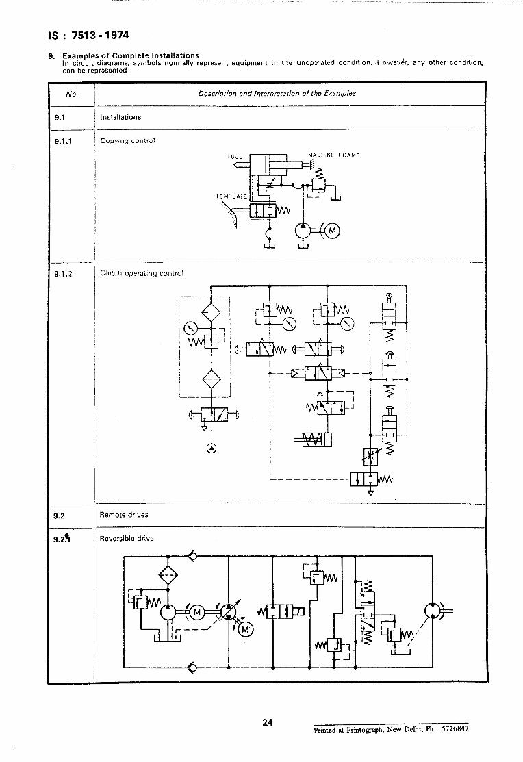
9. Examples of Complete Installations In circuit diagrams, symbols normally represent equipment in the unoperated condition. Howevdr, any other condition, can be represented
I
No. 1 Description and Interpretation of the Examples
-~
9.1 installations
9.1 .I Copying control
ACHINE FRAt.‘E
1
I
!
, I
/ I I /
i
s
-_
9.1.2 CjuEh operatiflg control
9.2 Remote drives
9.29 Reversible drive
24 Printed at Printograph, New Delhi, F’h : 5726847
AMENDMENT NO. 1 JULY 1985 TO
Is : 7513 - 1974 GRAPHICAL SYMBOLS FOR FLUID POWER
SYSTEMS
( Page 2, clause 2.1.2.5, under column ‘ Ap$ication ’ ) - Substitute ’ for ‘ oscillator ’ .
semi-rotary actuator~oscillator’
( Page 7, clause 3.7, under column ’ Symbol ’ ) - Delete the symbol for ‘ hydraulir: to pneumatic 1,
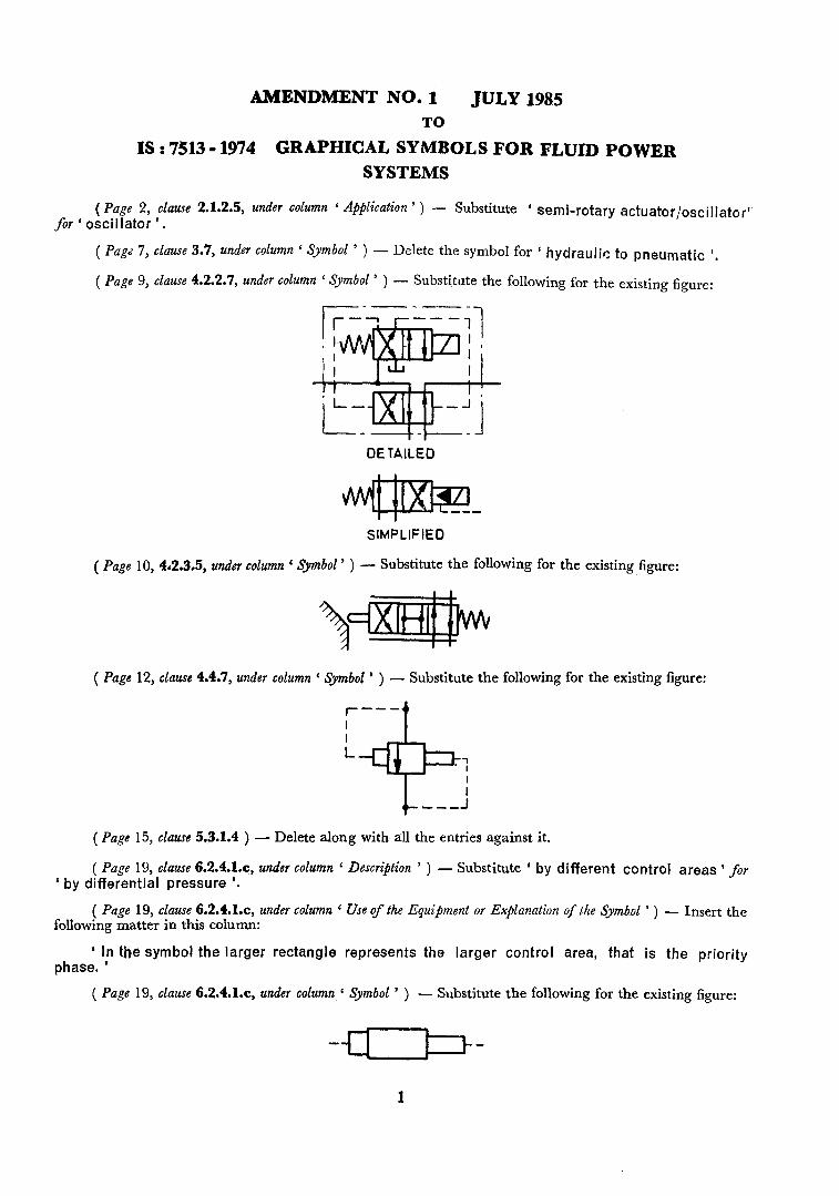
( Page 9, clause 4.2.2.7, under column ’ Symbol ’ ) - Substitute the following for the existing figure:
DE TAILED
SIMPLIFIED
( Page 10, 4‘2.3.5, under column ‘ Symbol ’ ) - Substitute the following for the existing figure:
( Page 1‘2, clause 4.467, under column ( Symbol ’ ) - Substitute the following for the existing figure:
I- --- t
( Page 15, clause 5.3.1.4 ) - Delete along with all the entries against it.
( Page 19, clause 6.2.4.1x, under column ‘ ‘ by differential pressure ‘.
Description ’ ) - Substitute ’ by different control areas 1 for
( Page 19, clause 6.2.4.1.q under column ‘ Use of the Equipment or Explanation of the Symbol ’ ) - Insert the following matter in this column:
‘ In the symbol the larger rectangle represents the larger control area, that is the priority
phase. ’
( Page 19, clause 6.2.4.1.c, under column ‘ Symbol ’ ) - Substitute the following for the existing figure:
---
1
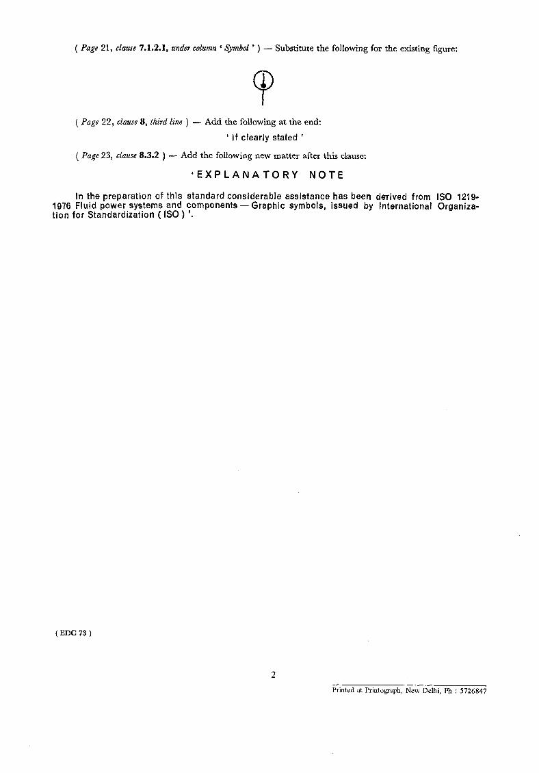
( Page 21, clause 7.1.2.1, under column ‘ Symbol ’ ) - Substitute the following for the existing figure:
9 1
( Page 22, clause 8, third line ) - Add the following at the end:
’ if clearly stated ’
( Page 23, clause 8.3.2 ) - Add the following new matter after this clause:
‘EXPLANATORY NOTE
In the preparation of this standard considerable assistance has been derived from IS0 1219- 1976 Fluid power systems and components - tion for Standardization ( ISO) ‘.
Graphic symbols, issued by International Organiza-
(EDC73)
2
Printed at Printogaph, New Delhi, Ph : 5726847


![[XLS]static.springer.comstatic.springer.com/sgw/documents/1372031/application/... · Web view0 1972 1973 1973 1973 1973 1974 1974 1974 1974 1974 1974 1974 1974 1974 1974 1974 1974](https://img.pdfslide.us/doc/110x75/5ae3d8767f8b9a5d648e7b9b/xls-view0-1972-1973-1973-1973-1973-1974-1974-1974-1974-1974-1974-1974-1974-1974.jpg)