Embed Size (px)
Citation preview

Disclosure to Promote the Right To Information
Whereas the Parliament of India has set out to provide a practical regime of right to information for citizens to secure access to information under the control of public authorities, in order to promote transparency and accountability in the working of every public authority, and whereas the attached publication of the Bureau of Indian Standards is of particular interest to the public, particularly disadvantaged communities and those engaged in the pursuit of education and knowledge, the attached public safety standard is made available to promote the timely dissemination of this information in an accurate manner to the public.
इंटरनेट मानक
“!ान $ एक न' भारत का +नम-ण”Satyanarayan Gangaram Pitroda
“Invent a New India Using Knowledge”
“प0रा1 को छोड न' 5 तरफ”Jawaharlal Nehru
“Step Out From the Old to the New”
“जान1 का अ+धकार, जी1 का अ+धकार”Mazdoor Kisan Shakti Sangathan
“The Right to Information, The Right to Live”
“!ान एक ऐसा खजाना > जो कभी च0राया नहB जा सकता है”Bhartṛhari—Nītiśatakam
“Knowledge is such a treasure which cannot be stolen”
“Invent a New India Using Knowledge”
है”ह”ह
IS 5674 (1970): 16 mm projector spools [MED 32:Photographic Equipment]

.
IS:5674-1970
Indian Standard SPECIFICATION FOR
16 mm PROJECTOR SPOOLS
Cinematographic Equipment Sectional Committee, ETlk 47
Chairman
SHRI P. N. DEOBHAKTA
Members
Representing
Directorate General of Technical Development, New Delhi
SHRI BALRAJ BHANOT ( Altsrnate to Shri P. N. Deobhakta )
SHRI S. N. AGARWAL Cinecita Private Limited, Bombay SHRI J. R. NAHAR ( Alternate )
SHRI J. N. BIURIA Films Division (Ministry of Information & Broad- casting ), Bombay
Cinesales Corporation, Delhi ( Alternate 1
SHRI Y. R. CHAUHAN SHRI R. S. CHAUHAN
DR A. F. CHHAPGAR
LT-COL M. B. DWIVED~
SHRI D. C. VAT~A ( Alternate ) SHRI BHU~ON GHOSH
SHRI MANNA LADIA ( Alternate ) SHRI P. H. KAPILA
National Physical Laboratory ( Acoustics Division ) ( CSIR), New Delhi
Department of Defence Production ( Ministry of Defence )
Cine Mechanical Works, Calcutta
SHRI A. MAJID KAZI SHRI P. N. KOHLI
Kine Engineers, Bombay Amco Engineering Corporation, Madras Department of Teaching Aids, National Council of
Educational Research and Training, New Delhi \ SHRI N. P. BHATTACHARYA ( Alternate J
SHRI B. A. MISTRY In personal capacity ( Hari Niwas, Bombay ) SHRI M. E. NAGARAJAN Photophone Equipments Limited, Bombay
SHRI R. RAJAGOPALAN Alternate ) SHRI P. J. PATEL Film Federation of India, Bombay SHRI C. S. RAMANATHAN Hindustan Photo Films Manufacturing Co Ltd,
Ootacamund DR S. K. JAIN ( Alternate)
SHRI RAM PRASAD
SHRI M. SANKARALINGAM
National Physical Laboratory ( Optics Division ) ( CSIR ), New Delhi
Directorate General of Supplies and Disposals, New Delhi
SHRI G. R. BHATIA ( Alternate )
( Continued on Page 2 )
INDIAN STANDARDS INSTITUTION MANAK BHAVAN, 9 BAHADUR SHAH ZAFAR MARG
NEW DELHI 1
IS:!3674-1970
( Continuedfrom page 1 )
Members
SHRI U. S. SAXENA
SHRI V. J. B. WADIA SHRI S. M. BHINZ ( Alternate )
SHRX Y. S. VENXATESWARAN, Director ( Elec tech )
Representing
Film Institute of India ( Ministry of Information & Broadcasting ), Poona
Wadia Lighting Equipment Pvt Ltd, Bombay
Director General, IS1 ( Ex-ojicio Member)
Secretary
SHRI T. RAJAFCAMAN
Deputy Director ( Elec tech ), IS1
2
IS : 5674 - 1970
Indian Standard SPECIFICATION FOR
16 mm PROJECTOR SPOOLS
0. FOREWORD
0.1 This Indian Standard was adopted by the Indian Standards Institution on 6 June 1970, after the draft finalized by the Cinematographic Equipment Sectional Committee had been approved by the Electrotechnical Division Council.
0.2 Work on the formulation of standards for various cinematographic equipment has been undertaken with a view to establishing acceptable levels of quality and performance as well as bringing about a degree of interchangeability in these units. This is one of the series of Indian Stand- ards on cinematographic equipment.
0.3 For the purpose of deciding whether a particular requirement of this standard is complied with, the final value, observed for calculated, expressing the result of a test, shall be rounded off in accordance with IS : 2-1960*. The number of significant places retained in the rounded off value should be the same as that of the specified value in this standard.
1. SCOPE
1.1 This standard prescribes the dimensions and requirements for projector spools for 16 mm cinematograph film from 15 ,to 600 m capacity
2. TERMINOLOGY
2.0 For the purpose of this standard, the following definitions shall apply.
2.1 Lateral Run-Out - The deviation of any point of the flange rim from its intended plane of rotation,
2.2 Flange Deflection - Flange deflection is the amount of deflection of the spool flange for a given specified load.
*Rules for rounding off numerical values ( raised ).
3
IS : 5674 - 1970
2.3 Type Tests -Tests carried out to prove conformity to the require- ments of this standard. These are intended to check the general qualities and design of a given type of component.
2.4 Acceptance Tests - Tests carried out on samples selected from a lot for the purpose of acceptance of the lot.
2.4.1 Lot -All spools of the same type, grade, category and ratings manufactured by the same factory during the same period using the same process and materials.
2.5 Routine Test - Test carried out on every spool to check the require- ments which are likely to vary during production.
3. MATERIAL, CONSTRUCTION AND WORKMANSHIP
3.1 Material - All spools shall be manufactured from materials of corro- sion resistant type or shall be treated to resist corrosion.
3.2 Workmanship and Finish - All spools shall be manufactured in a thoroughly workmanlike manner and in accordance with good engineering practice. They shall be free from sharp edges. The finish shall protect the spool adequately against corrosion under normal conditions of use. Such finish shall not prevent the discharge of static electricity from the film to the spindle of the projector or winding machine.
3.3 Running-Balance - The spools when made up, shall provide a satis- factory running-balance.
3.4 The flanges shall be of such design and be made of such material as not to crack nor to take a permanent set, and the bore shall be capable of withstanding the expected degree of wear. If non-metallic, the material shall be non-flammable. buckling.
The flanges shall be free from warping or
3.5 The hub may be of either solid or hollow construction but shall be so designed as to provide for:
a) the spindle mounting and drive specified in 3.8. b) a method of fihn attachment complying with 3.10, and c) the finger holes specified in 3.11.
3.6 The flanges shall be firmly and rigidly attached to the hub, so that they will not come apart under normal conditions of use. They shall be so designed as to provide the flat clamping faces specified in 3.3.
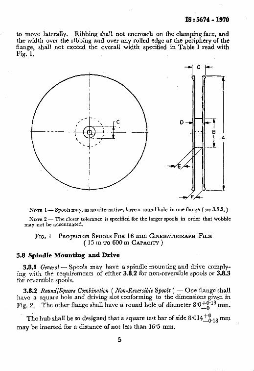
3.7 The flanges may be ribbed, but such ribbing shall be so designed that ~ there is no continuous concentric groove which would permit a layer of film
4
IiS : 5674 - 1970
to move laterally. Ribbing shall not encroach on the clamping face, and the width over the ribbing and over any rolled edge at the periphery of the flange, shall not exceed the overall width specified in Table 1 read with Fig. 1.
NOTE I-- Spools may, as an alternative, have a round hole in one flange ( s.s 3.8.2. )
NOTE 2 - The closer tolerance is specified for the larger spools in order that wobble may not be accentuated.
FIG. 1 PROJECTOR SPOOLS FOR 16 mm CINEMATOGRAPH FILM ( 15 m TO 600 m CAPACITY )
3.8 Spindle Mounting and Drive
3.8.1 General - Spools may have a spindlemounting and drive comply- ing with the requirements of either 3.8.2 for non-reversible spools or 3.8.3 for reversible spools.
3.8.2 Round/Square Combination ( Xon-Reversible Spools ) - One flange shall have a square hole and driving slot conforming to the dimensions given in Fig. 2. The other flange shall have a round hole of diameter 8SO-$13 mm.
The hub shall be so designed that a square test bar of side 8*014~~.,, mm
may be inserted for a distance of not less than 16.5 mm.
5
_-
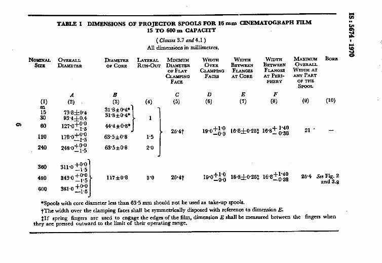
TABLE 1 DIMENSIONS OF PROJECTOR SPOOLS FOR 16 mm CINEMATOGIUI’H FILM
240
15 TO 609 m CAPACITY
( Clauses 3.7 and 4.1 )
All dimensions in millimetres.
DL4METEa LATERAL MINIMUM Wmw Wmw WIDTH MAXIMUM BORE
OF CORE RUN-OUT DIAMETER OVER BETWEEN BETWEEN OVERALL OF FLAT CLAMPING FLANGES FLANGES WIDTH AT
CLAMPING FACET AT CORE AT PERI- ANY PART
31’8fO’4* 31*8f@4*
44’4f@8*
63.5kO.8
63.5iO.8
117kO.8
FACE PIiERY
2@4t 19*0_+;:0, 1&8f@26$ 18.8-t A:$ 21’ -
OF THE
SPOOL
(9) (10)
2&4 See Fig. 2 and 8.8
*Spools with core diameter less than 63.5 mm should not be used as take-up spools.
tThe width over the clamping faces shall be symmetrically disposed with reference to dimension E. $If spring fingers are used to engage the edges of the film, dimension E shall be measured between the fingers when
they are pressed outward to the limit of their operating range.
IS: 5674 - 1970
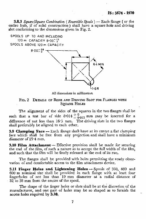
3.8.3 Square/Square Combination ( Reversible Spools ) - Each flange ( or the entire hub, if of solid construction ) shall have a square hole and driving slot conforming to the dimensions given in Fig. 2.
SPOOLS UP TO AND INCLUDING
120 m CAPACITY 8~0c1~‘~~
SPOOLS ABOVE 120m CAPACITY
All dimensions in millimetres.
FIG. 2 DLTAILS OF BORE AND DRIVING SLOT FOR FLANGES WITH SQUARE HOLES
The alignment of the sides of the squares in the two flanges shall be such that a test bar of side PO14 2 E.013 mm may be inserted for a difference of not less than 16.5 mm. The driving slots in the two flanges shall preferably be ahgned to each other.
3.9 Clamping Face - Each flange shall have at its centre a flat clamping face which shall be free from any projection and shall have a minimum diameter of 25.4 mm.
3.10 Film Attachment - Effective provision shall be made for securing the end of the film, of such a nature as to accept the full width of the film, and such that the film will be freely released at the end of its run.
The flanges shall be provided with holes permitting the ready obser- vation ~of and comfortable access to the film attachment device.
3.11 Finger Holes and Lightening Holes - Spools of 360, 480 and 600 m nominal size shall be provided in each flange with at least four fingerholes of not less than 19 mm diameter at a radial distance of 32 to 38 mm from the centre of the spool.
The shape of the finger holes or slots shall be at the discretion of the manufacturer, and one pair of holes may be so shaped as to furnish the access holes required by 3.10,
7
IS : 5674 - 1970
The flanges of all sizes of spools may be provided with such lightening holes as the manufacturer may desire.
3.12 Eccentricity of the flanges and core with respect to the spindle hole axis shall not exceed the total radius variation ( total indicator reading ) of =t: 0.8 mm.
3.13 Maximum Weights -The finished spools of 240, 360, 480 and 600 m capacity shall not exceed the following weights:
Nominal Size of Spool ( Capacity )
m
240 360 480 600
4. DIMENSIONS
Recommended Maximum Weight
g 425 500 600 900
4.1 The spools shall conform to the dimensions given in Table 1 read with Fig. 1 and Fig. 2.
5. MARKING
5.1 All spools shall be marked on the flange with round holes ( in non- reversible spools ) and on any of the sides ( in reversible spools ) legibly and indelibly with the following:
a) Name and/or code number of the manufacturer,
b) Capacity* of the spool in m, and
c) Country of manufacture,
5.1.1 The spools may also be marked with the IS1 Certification Mark.
NOTE - The use of the IS1 Certification Mark is governed by the provisions of the Indian Standards Institution ( Certification Marks) Act, and the Rules and Regula- tions made thereunder. Presence of this mark on products covered by an Indian Standard conveys the assurance that they have been produced to comply with the requirements of that standard, under a well-defined system of inspection, testing and quality control during production. This system, which is devised and supervised by IS1 and operated by the producer, has the further safeguard that the products as actually marketed are continuously checked by IS1 for conformity to the standard. Details of conditions, under which a licence for the use of the IS1 Certification Mark may be granted to manufacturers or processors, may be obtained from the Indian Standards Institution.
*A scale showing film loading may be marked instead.
8
n
IS : 5674 - 1970
6. TESTS
6.1 Classification of Tests
6.1.1 Type Tests - The following shall constitute type tests:
a) Visual examination and dimensional check up ( see 6.2 ), b) Test for lateral run-out ( see 6.3 ), c) Test for flange rigidity ( Tee 6.4 ), d) Test for drop resistance ( see 6.5 ), and e) Test for corrosion resistance ( see 6.6-),
6.1.2 Acceptance Tests - The following shall constitute acceptance tests:
a) Test for lateral run-out ( sek 6.3 ), b) Test for flange rigidity ( see 6.4 ), and c) Test for drop resistance ( see 6.5 ),
6.1.3 Routine Tests -Visual examination and dimensional check up ( 6.2 ), and t.est for lateral run-out ( 6.3 ) shall be carried out as routine tests.
6.2 Visual Examination and Dimensional Check Up-The spools shall be examined visually and checked for the dimensions specified in the standard. The spool surfaces and mounding surfaces shall be free from voids, nicks, scratches and other surface imperfections. Surface imperfec- tions which do not fall within an area of a circle of 1.5 mm diameter, and surface imperfections such as scratches, which exceed 12’5 mm in length shall be considered of a size to constitute rejection. The spools shall conform to all the dimensions with the permitted tolerances given in this standard.
6.3 Test for Lateral Run-Out - Each finished spool shall be tested for true running by being mounted on a true spindle fitted with a truly normal clamping face, 25.4 mm diameter to which the spool is clamped. The spindle shall be square in section, of 8.014 2 00.013 width across flats,
with a truly co-axial cylindrical portion 8.014 2 :.013 mm diameter, the length of the square portion being such that the spool may rest freely upon the clamping face.
When the mounted and clamped spoo! is rotated, each flange at its periphery shall run true,. in a plane perpendicular to the axis of the spindle, with the maximum dial indicator reading not exceeding 3.2 mm.
9
IS : 5674 - 1970
6.4 Test for Flange Rigidity
6.4.1 A good projection spool shall meet certain minimal physical strength requirements, particularly with respect to the flanges. A spool that meets this standard shall pass the following test for flange rigidity.
6.4.1.1 Make three posts that are placed 120” apart and constructed so they support a short length of the rim of the spool for a distance of 3.2 mm radially. Apply a load of 225 g over a central area not greater than 32 mm in diameter. Measure the vertical location of this area with a dial indi- cator. Add 450 g and measure again. The additional deflection caused by the 450 g weight over that given by the 225 g weight should be less than 0.9 mm. Repeat the process on the other flange.
6.5 Test for Drop Resistance -When a fully loaded spool is packaged in its appropriate can* or container, and the packaged spool dropped through a vertical distance of at least I.5 m above a concrete floor to strike on edge, the spool shall not exhibit any splitting, cracking or chipping.
6.6 Test for Corrosion Resistance - Test for corrosion r&stance of the spools shall be conducted as specified in Appendix A.
APPENDIX A
( CZause 6.6 ) TEST FOR CORROSION RESISTANCE
A-l. APPARATUS
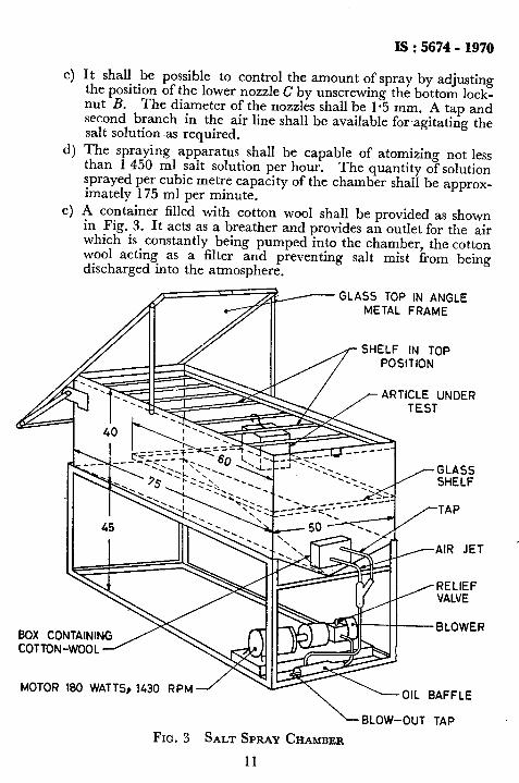
A-l.1 Salt Spray Chamber - The chamber for this test shall be so cons- tructed that the salt spray is produced’in the lower part of the chamber, in the upper part of which the parts to be exposed are suspended. The con- struction of the ceiling, walls and other parts of the chamber shall be such that no condensate can drip on the test specimen. The spray shall be pro- duced by an atomizer employing compressed air free from all impurities.
A-1.1.1 In general, a salt spray chamber shown in Fig. 3 with a spray- ing arrangement as shown in Fig. 4 and complying with the following requirements would be suitable:
_
a) The cabinet shall approximately be of the dimensions shown, and the cabinet and its internal fittings shall be made of monel metal or other suitable material. A shelf, capable of being fitted in the upper or lower part of the cabinet, shall be provided.
b) The air used for atomizing the salt solution shall be clean. It shall be possible to adjust the pressure by a relief valve or by the pressure outlet of the blower.
&c also Specification for cans for 16 pm projector spools ( under frint ).
IO
IS:5674 -1970
It shall be possible to control the amount of spray by adjusting the position of the lower nozzle C by unscrewing the bottom lock- nut B. The diameter of the nozzles shall be l-5 mm. A tap and second branch in the air line shall be available for agitating the salt solution was required. The spraying apparatus shall be capable of atomizing not less than 1 450 ml salt solution per hour. The quantity of solution sprayed per cubic metre capacity of the chamber shall be approx- imately 175 ml per minute. A container filled with cotton wool shall be provided as shown in Fig. 3. It acts as a breather and provides an outlet for the air which is constantly being pumped into the chamber, the cotton wool acting as a filter and preventing salt mist from being discharged into the atmosphere.
SS TOP IN ANGLE METAL FRAME
SHELF IN TOP POSITION
r ARTICLE UNDER
es..., a_ .._. . . . . ..^ DUA LUN IAININU
COTTON-WOOL 1
MOTOR 180 WATTS9 1430 RPM
L BLOW-OUT TAP
FIG.~ SALT SPRAY CHAMBER
11
IS : 5674 - 1970
BOX CONTAINING
FIG. 4
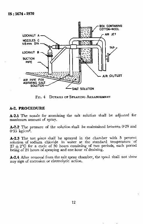
A-2. PROCEDURE
L, SALT SOLUTION
DETAILS OF SPRAYING ARRANGEMENT
A-2.1 The nozzle for atomizing the salt solution shall be adjusted for maximum amount of spray.
A-2.2 The pressure of the solution shall be maintained between O-29 and 0.35 kg/cm2.
A-2.3 The test piece shall be sprayed in the chamber with 5 percent solution of sodium chloride in water at the standard temperature of 27 f 2°C for a cycle of 50 hours consisting of two periods, each period being of 24 hours of spraying and one hour of draining.
A-2.4 After removal from the salt spray chamber, the spool shall not show any sign of corrosion or electrolytic action.
12


![THE PATENTS ACT, 1970 - National Biodiversity Authoritynbaindia.org/uploaded/Biodiversityindia/Legal/14. The Patents Act, 1970.pdf · THE PATENTS ACT, 1970 [39 of 1970, dt. 19-9-1970]](https://img.pdfslide.us/doc/110x75/5e4d13e80eb10b1fef07cead/the-patents-act-1970-national-biodiversity-the-patents-act-1970pdf-the.jpg)