Embed Size (px)
Citation preview

Disclosure to Promote the Right To Information
Whereas the Parliament of India has set out to provide a practical regime of right to information for citizens to secure access to information under the control of public authorities, in order to promote transparency and accountability in the working of every public authority, and whereas the attached publication of the Bureau of Indian Standards is of particular interest to the public, particularly disadvantaged communities and those engaged in the pursuit of education and knowledge, the attached public safety standard is made available to promote the timely dissemination of this information in an accurate manner to the public.
इंटरनेट मानक
“!ान $ एक न' भारत का +नम-ण”Satyanarayan Gangaram Pitroda
“Invent a New India Using Knowledge”
“प0रा1 को छोड न' 5 तरफ”Jawaharlal Nehru
“Step Out From the Old to the New”
“जान1 का अ+धकार, जी1 का अ+धकार”Mazdoor Kisan Shakti Sangathan
“The Right to Information, The Right to Live”
“!ान एक ऐसा खजाना > जो कभी च0राया नहB जा सकता है”Bhartṛhari—Nītiśatakam
“Knowledge is such a treasure which cannot be stolen”
“Invent a New India Using Knowledge”
है”ह”ह
IS 4111-5 (1993): Code of practice for ancillary structuresin sewerage system, Part 5: Tidal outfalls [CED 24: PublicHealth Engineering.]


IS 4111( Part 6 ) : 1993
Indian Standard
CODEOFPRACTKEFOR ANCILLARYSTRUCTURESINSEWERAGESYSTEM
PART 5 TIDAL OUTFALLS
UDC 628-241-2.217
cc) BIS 1993
BUREAU OF INDIAN STANDARDS MANAK BHAVAN, 9 BAHADUR SHAH ZAFAR MARG
NEW DELHI 110002
-__.
May 1993 Price Group 6
Water Supply and Sanitation in Building Sectional Committee, CED 24
FOREWORD
This Indian Standard was adopted by the Bureau of Indian Standards, after the draft finalized by the Water Supply and Sanitation in Building Sectional Committee had been approved by the Civil Engineering Division Council.
Whenever in a sewerage system ancillary structures like manholes, flushing tanks, inverted syphons, pumping stations and pumping mains, tidal outfalls, etc are provided these should be properly designed. This part of the standard on ancillary structures in sewerage system provide guidance for design and construction of tidal outfall. The other parts of the standard are:
Part I Manholes (first revision )
Part 2 Flushing tanks (first revision )
Part 3 Inverted syphons ($rst revision j
Part 4 Pumping stations and pumping mains ( rising mains )

Indian Standard
IS 4111( Part 5 ) : 1993
CODEOFPRACTICEFOR I ANCILLARYSTRUCTURESINSEWERAGESYSTEM
PART 5 TIDAL OUTFALLS
1 SCOPE
1.1 This standard (Part 5) specifies requirements on philosophy, location, design, construction and equip- ment for installation of tidal outfalls used in sewerage system for economic disposal of waste water into the sea.
2 REFERENCES
2.1 The Indian Standards listed in Annex A are neces- sary adjuncts to this standard.
3 PHILOSOPHY OF INSTALLING TIDAL 01IJT- FALL
3.1 The underlying philosophy being safe and economic disposal of waste without any significant detrimental effect on the receiving water that would impair its beneficial use.
3.2 In the engineering analysis of tidal outfall disposal of waste water, following aspects shall be considered :
a) Protection of public health,
b) Avoidance of nuisance conditions,
c) Aesthetic requirements,
d) Influence on marine flora and fauna,
e) Economic of reclamation, and
f) Overall economics of outfall disposal system.
4 DESIGN CONSIDERATIONS
4.0 Principle and Objectives
4.1 The function of a tidal outfall is to discharge waste water to the sea after pre-treatment which includes grit removal and mechanical treatment, up to a distance from the shore to ensure the dilution, dispersion and natural purification so as to reduce the concentration of harmful organisms and chemicals present in waste water to the acceptable levels in inshore water used for fisheries, recreational purposes etc.
4.2 Water Quality Criteria
4.2.1 The desired inshore water quality will depend upon the local usage of the receiving water for bathing, fishing, shell fishery and recreational activities. *
4.2.2 Faecal (Enteric) bacteria are found insewage and waste water in large numbers. They can readily be detected when dispersed in sea water and are used as indicator for detecting the presence of pathogenic or- ganisms and chemicals even if they are found in much smaller concentrations in waste waters.
4.2.3 The length of the sea outfall should be sufficient to ensure enough dilution and dispersion characteristics such that conditions in receiving water may satisfy certain specified water quality criteria in accordance with IS 2490 (Part I) : 1981.
4.2.4 Formation of surface sticks, which are’caused by greasy material in waste watershould be minimized by ensuring rapid dilution.
4.2.5 Quality of receiving water should be related to recreational use. The waste water discharge should not detract from visual aesthetic quality of water.
4.3 Fisheries
Shell fishes and certain other fishes are susceptible to the effects of pollutants discharged in the sea, and may be destroyed by bacterial infection, toxic substances, or siltation of suspended in their feeding ground and also the spawning ground for fish may be affected deleteriously by such conditions. Most of the marine life existing on sea bed which settle to sea bottom. Mobile organisms tend to avoid such regions. Sudden release of certain waste may give rise to acute toxic conditions in marine environment, depletion of dis- solved oxygen which in acute cases may result in the mass deaths of fishes by asphyxiation.
4.4 Pre-treatment
4.4.1 To protect the outfall system against blockages to minimize visual pollution, it is desirable to pretreat and control the discharge of waste water.
4.4.2 The following are the desirable functions to:
a> b)
-1 . .
4 e)
Remove grit;
Remove debris, namely rags and plastics from flow;
Disintegrate floatable material such as faecal matter, to ensure rapid dispersion in the sea; Remove greasy materials; and
Provide further treatment, i.e., sedimentation, if so required, generally avoided.
4.4.3 During installation of pre-treatment head-works, environmental considerations should be taken care of and precaution should be taken regarding noise, odour, safety and appearance. .
4.4.4 The economic balance between the degree of pre-treatment on land and the length of the o%fall is one of the major design consideration. Generally a long outfall with limited pre-treatment is found to be economical and favourable.
4.5~ Diffuser Systems
4.5.1 Requirements of the optimum discharge location for dispersion is necessary to select a suitable diffuser array of single or multiple ports along final length of outfall. Careful hydraulic analysis of flow diversion to the ports in the diffuser manifold and the overall head loss within the complete outfall system should be
“_.
1
IS 4111 ( Part 5 ) : 1993
checked to ensure that beaches used for bathing, boat- ing, sports are not polluted by smell, solids and slicks. It is necessary to achieve some initial dilution before final discharge. Initial dilution for given water depths, sea water density, waste water density, discharge pipes diameter and ambient current velocity can be found out readily by in-situ tracer tests.
4.5.2 While designing elements of outfall disposal system that is dispersion and dieoff, initial dilution, diffuser system and outfall pipe care should be taken to determine the effects of seawater entering the outfall system at low flows.
4.6 Nature of Discharge
4.6.1 Components of domestic waste water are prone to quick degradation in sea water. The combination of degradation and dilution renders waste harmless in the salt waterenvironment. In the naturalprocessofgrowth and decay, sufficient quantity of oxygen is usually available in waste water. Ultra violet light from sun acts as disinfecting agent in killing bacteria, while currents and turbulence enhance dilution and sedimentation takes place over a wide area. Where decomposed material once again enters the lower level food chain.
4.6.2 Substances resistant to degradation (that is non- degradable) in the sea enviromnent shall be checked if discharged continuously or in large quantities. This situation may arise a tplaces where waste waterconsists of combined effluents of domestic and industrial dis- charges. Among all pollutants the most noxious and nofl-degradable which have the tendency to bio-con- centrate (that is bio-magnificate) in marine environ- ment are halogenated organic compounds, mercury, lead, arsenic, cadmium, hydrocarbons, oils and sys- thetic substances. For their tolerance limits see IS 2490 (Part 1) : 1981.
4.7 The outfall structures discharging waste water should be at a sufficient distance from intakes supply- ing process or cooling water for industrial use, or from the vicinity of fish farming installations to prevent contamination.
4.8 In the design of outfall structures as far as possible the advantage of self-purification that is natural degrada- tion shall be availed. The parameters concerned are biochemical oxygen demand and suspended solids, the nutrient elements like, nitrogen and phosphorous.
4.9 The magnitude ofwaste water flow depends on the type of existing sewerage system whether combined or separate (that is, foul sewage and surface water). Designed flow can be found out as per IS 2951 (Parts 1 and 2) : 1965. While designing and deciding about the size of outfall structure, nature of discharge, existing flows along with provision for increases as a result ofvariation in population and seasonal variation, shall be by gravity if sufficient head is available otherwise pumping can bc adopted. If pumps are used, generator shall be installed to prevent flooding in the event of power supply failure (see also IS 5600 : 1970).
5 INVESTIGATIONS AND RECORDS
5.1 Uptodate hydrographic charts anQrecords shall be
collected to get information about water depths, nature of sea bed, obstructions, velocities at desired positions. This data is normally utilized for preliminary analysis.
5.2 Geological maps and records shall be made avail- able from concerned departments (that is, Geological Survey of India), giving details ofboreholes, drillings, nature of sea bed, nature of bed expected to carry outfall structure and presence of slips, faults etc.
5.3 Oceanographic records giving details about past bchaviour of waves over a specified period shall be obtained from the department of oceanography.
5.4 Tidal information and current records give broad picture of tidal current activity and continuous records of at least one year shall be made aJailable and studied to find tidal variations.
5.5 Other Possible Effects on Currents
5.5.1 Littoral Drift
The direction and trend of the littoral drift may in course of time affect the currents near the shore, and past records over as long a period as possible should be investigated. Extensive littoral drift may alter condi- tions in the immediatevicinity of the outfall construc- tion and in extreme cases it may undermine pipe structure also. As far as possible aerial photograph giving littoral drift and coastal morphology shall be made available.
5.5.2 Fresh Waer Dischrge from Heavy Rninslnlnnd
Serious interference with normal tidal currents may be caused by the discharge into an estuary of large quan- tities of fresh water due to abnormal heavy rains inland. These discharges may also carry a heavy load of agriculturally derived nutrient which can create eutrophic effects in estuary with poor flushing charac- teristics.
5.5.3 Groynes, Tmining Wrrlls or Other Works in the Vicinity
Particular attention should bc paid to the position of existing or contemplated groynes or other works which may either cause the scour of the current to undermine the oulfall pipe or may cause the beach to fill up and smoothen the outlet. If the sewer outfall is above beach level, it may itselfact as a groyne and affect the stability of the beach.
5.6 Meteorological Records
5.6.1 The direction and force of wind have a direct influence on local conditions. Sometimes the combina- tion of wind and tide may result in.abnormally high or low tidal levels in the area. All historical and con- tinuous records should be obtained from meteorologi- cal department.
5.7 Local Information
5.7.1 Local knowledge and experience of boatmen, fishermen and others with regard to exceptional tides, tidal bores, wind effect and any other peculiarities of the locality should always be taken into consideration.
2
6 DETAILED STUDIES
6.1 Tidsl Information
6.1.1 Tide Table
An essential preliminary to the design of a tidal sewer outfall in a tide-table for the locality when the tide tables for the locality of the proposed outfall are not available, it is not always safe to interpolate figures between the two nearest available tide-tables, as tide levels and time may vary considerably in short distances.
6.1.2 Tidal Records
In the absence of a tide-table, records of time and height of tides covering at least one year should be obtained. If the proposed site is an estuary, the appropriate river authority might have full tidal records which could be made available; otherwise fresh tidal observations should be made. For this purpose a recording tidegauge should be installed as near as practicable to the site of the proposed outfall, in a position where it is sheltered from abnormal.weather conditions and where there is enough water to prevent the float grounding on the floor of the chamber. Continuous records should be calculated from the following dbsetvations:
a) Mean low water (springs),
b) Mean high water (springs),
c) Mean low water (neaps),
d) Mean high water (neaps), and
e) Mean tidal Icvcl.
III addition, the highest and lowest recorded tide levels in the district should bc ascertained.
6.2 Tidal <.hrreuts
6.2.1 The fullest possible information regarding the tidal currents is necessary before deciding on the loca- tion of a sewer outfall into tidal waters. Some informa- tion and guidance may be obtained from the local river authority and local laymen. HoGever, precise survey data may usually be required.
6.2.2 Observation of Tidal Currents
6.2.2.1 Observation byfloats
The wastewater from outfall usually rises to the sea surface before being carried away by the tidal current for lateral and deep dispersion. Wind direction and strength may affect the current, particularly at or near the water surface. So it is essential to supplement the information obtained as above by a series of careful float observations at the propbsed point of discharge, and the results of the observations properly interpreted.
6.2.2.2 Period of observation
Although some idea ofbehaviour of tidal currents can be obtained by float observation taken over one conl-
plete lunar cycle of tides but observations should be taken over as long a period a possible including times when the most undesirable conditions, particularly on- shore winds, exist. The observations to be of real value, should be taken over for at least one year.
IS 4111 (Part 5) : 1993
6.2.2.3 Intervals of release offloats
Floats shall be released from the site of outlet of the proposed outfall at regular intervals of time covering a complete cycle of tide, preferably commencing at high water. The release of floats a& one hour intervals can give quite reliable information on the trend of the currents, but the interval may have to be reduced if the first observations taken, show such action to he necessary.
6.2.2.4 Movement can be monitored by small fnarker devices designed to float virtually submerged’but still be visible from a boat. Suitable drift-card can be made from coloured plastics material to float on edge and just submerged. These drifters are released in quite large numbers.
6.2.2.5 Pole or stick floats are intended to integrate the water movement over a depth corresponding to their length. These floats are just submerged and fitted with a light weight identification flag. Measurements at greater depths can be made by drouge device, which may carry a radar reflector supported by line beneath a buoyant marker unit.
6.2.2.6 All types of floating devices are affected by wind. So it is preferred to calibrate their perCormnace with respect to a soluble water-tracer namely Dye.
6.2.2.7 Observations of float positions can be made by any one of the following:
a) Sextant method,
b) Two theodolites method, and
c) Electric methods.
It is always better to consult surveyor before carrying out above observatiom.
6.2.2.8 Time interval of readings should be about 15 minutes if feasible. After all float observations have been taken, they should be grouped together and plotted taking account of wind draft, soundings, survey map, and land marks. The information gained from current studies will give idea about the preliminary outfall discharge point to be selected.
6.2.3 Observations by Jelly Bottles
The use ofjelly bottles forobservations of tidal currents involves dropping a bottle containing hot liquified jelly into the sea. Themction and speed of the current are found by noting the angle at which the jelly solidifies.
6.2.4 Observation by Other Me!hods
Other methods, such as current meters, drop cards, dyes are now being used. Radio actirle tracers may be used for current observation under expert supervision. In case of current meters, recording instruments are available for continuously measuring current speed and direction at a point in the sea. Data can be recorded 011
magnetic tape in a form which can be transferred to computer.
6.3 Dilution and Dispersion
6.3.1 General _
There is a wide range of field studies which can
,
IS 4111 ( Part 5 ) : 1993
contribute information relevant to outfall design. Some are demanding in time and resources and even if com- pleted successfully, may not necessarily provide values of the diffusion parameters which are significantly different frotn those selected from literature, in relation to the short-term behaviour of sewage in the.sea. Care- ful thought should be given therefore, to the relevance of the measurements which are being proposed and the ultimate aims of the investigation. There are two tnain situations to consider first, where discharge is proposed into an area, as there is no existing sewage discharge and secondly, where an-existing outfall can be used as a source of sewa& to stu&y aspects of local dispersion performance. In some cases, it is necessary to differen- tiate between the effects of two or more sources of sewage by the use of added tracer substances.
6.3.2 Dye Dispersion Studies
Reference has been made to the use of dyes to calibrate the performance of floats and drougues (6.2.2.6). Measurements tnay be extended to de$ermine rates of horizontal and vertical tnixing (diffusibn coefficients). Dye concentration is tneasured in a fluorometer, the dye being made to fluorescence in ultra-violet light. Ideally, dye should be continuously injected, after prelitninary dilution, at the proposed outfall location over full tidal cycles. Continuous measurements of dye concentration at several depths are required along straight traverse lines through the dye plume between known starting and finishing points. Each set of transverses through the plume is then corrected for drift to some mean time (usually, that associated with the point of maximum concentration) and a synoptic plot obtained of dye concentration. The diffusion rate can then be estimated frotn the area enclosed by contours of particular concentration levels at various positions. Care in handling concentrated dyesolutions is essential to prevent false readings due to contamination. The behaviour of the particular dye used should be checked with respect to photochemical decay and absorption on particular matter.
6.3.3 Other Tracer Materials
Fluorescent dyes are the tnost suitable tracers for general purpose use, but other substances may be used in special cases. Radioactive tracers are particularly suitable for surveys where concentration is measured in situ, although specialized detection equiptnent is required, involving the etnployment of qualified radiochemi’sts to handle the tracer in concentrated form. Bacterial tracers are available, which can be detkcted after dilution by serveral orders of magnitude tnore easily than can dyes or radioactivity. However, as this method entails discrete satnples being taken for analysis, the technique is more applicable to studies of the long-term fate of sewage in the sea.
6.3.4 Bacteriological Studies
Where waste water is already being discharged to the sea in the-neighbourhood of the proposed new outfall, it is useful to exatnine spatial and tetnporal distribu- tions of indigenous sewage bacteria in the nearshore water. Satnples collected at regular intervals frotn
fixed stations can be analysed for coliform bacteria or faecal coliform and the results examined statistically to find correlations between bacterial counts and environ- mental parameters such as tidal state, wind velocity, sea state and solar radiation. The results may also indicate the presence of other sources of sewage .bacteria such as storm overflows or polluted river discharges.
6.3.5 Bacterial Mortality
A parameter of considerable importance to the predic- tion of the fate of sewage in the sea is the rate of mortality. Although many factors are probably in- volved in reducing bacterial counts in sea water, there is considerable evidence to show that sunlight is the most important controlling influence. The effective- ness of a particular level of solar radiation depends on the depth to which the light can penetrate the water column. In clear sea water, this may be several metres, but if the water is highly turbid, as is often the case in estuaries or at sea during storms, the depth of penetra- tion may be only a few centimetres. Salinity and temperature are also parameters of relevance to the inactivation of bacteria as they survive considerably longer in fresh water than in salt water under otherwise similar conditions. Measurements of turbidity, salinity and temperature should be included therefore in water quality surveys.
The rate of bacterial mortality in sea water is described by the T period, which is the time required for 90 percent of bacteria to die off Tperiods should be locally detertnined but can vary at the satne site between less than 1 hour to over 48 hours.
6.3.6 Model Studies
The complexity of combining the dispersion and decay processes affecting patches of diluted sewage of various ages requires the use of computer models. A good degree of realism may be obtained by using a hydrodynatnic model to estimate the pattern of tidal currents over a whole area; they should be calibrated and validated from field measurements. These results can then be used in dispersion models, calibrated frotn dilution, dispersion and decay studies, to study several options under a variety of conditions.
6.4 Biological Studies
Possible effects of domestic sewage on marine flora and fauna can be examined in two ways: by in situ monitoring’and comparison of conditions in polluted and similar control areas, or by toxicity tests in the laboratory using samples of dotnestic sewage diluted with sea water.
The procedures adopted by the relevant authority for the control of trade effluents within the drainage area of a tidal outfall should have regard to the effect of such discharges on the marine environment. Where the dis- charge of trade effluents to the outfall is pennitted, tests of acute or chronic toxicity to selected marine organisms may be desirable.
Where in situ monitoring is to be carried out, controlled observations should be made:
a) at the site of the outfall before its constr&tion,
4
IS 4111 ( I’m-t 5 ) : 1993
7 i,O~:A’I’lON
7.1 All hydrographic and geophysiral inforuiatiou ob- taiued should bc considered in reaching a decision al>(lul the 10catiou of the new outfall. SONIC of the original options will probably have been rejected during the course of the initial studies; it is likely that the final choicr will be couccrned with outfall length and method of construction. Ideally, prcdictcd perfor- mance should be compared with criteria required for adjacent recreational areas. Wherever possible, the out- fall pipe should be burried beneath the fore-shore to protect its exterior coating from wave damage.
The anienity value of local rccteational beaches should be taken int,o account in deciding the position aud length of a sea outl’all and the site of any associated headworks. The location and dcsigu ofany storm over- Ilows, and levels at which they are set to operate, should non be overlooked. It is iniportaut to ensure that visible solids, identifiable as of sewage origin, are not dis- charged. The time takeu for water to travel from the seaward end of the outfaIl to the shore in unfavourable wind cmlditious should be determined. The degree of diluGoe which is likely to be achlevrd in the minimum transit lime should be cstinmted.
7.2 Initial Dilution
Dilutiou performance and distribution of outlet ports should be calculated for a11 tidal conditions and C‘OLII- pared with a demand curve relariug dilution to the distance of offshore; there is no justification for requir- ing high initial-dilution performnce at points remote from recreational areas.
7.3 Tidal Conditions
Data 011 tidal rurrcnts should bc examined to ensure that mininluni dilution criteria will be satisfied at all stales of tide. In some cases, where slack-water condi- tions persist for a significant part of the tidal cycle, it may be necessary IO consider storing sewage during this critical period. Similarly, storagr sewage during this critical period may be required during the lower half of the tidal cycle a( sites where the tidal rauge is large and the water line recedes several kilonietres across the foreshore at low water. Ifpossible, however, storage should bc avoided, to discourage the estab- lishnient of auaerobic conditiom.
Residual movements of water in the longshore direc- tiou should be deduced and related to the time that sewage will remain in a particular area. The effects between Iaycrs of water at different depths should be determined. *
7.4 I,evels and Slope of Foreshore
Full information should be obtaiued as to the slope of the foreshore and its relation to the level of the shore and of the outfall sewer. The portion of the outfall on the foreshore should have as great a fall as possible and where practicable, should extend beyond low water marks of spring tides. Dilution and dispersal are con- siderably affected by the depth of water at the point of discharge. This, therefore, should be SO chosen to give the greatest practicable depth of disharge.
to provide a basis for direct conlparison with studies made after the oulfall is brought into USC; and
bj at a conlrol site in the vicinity which cxhibils sinlilar characteristics to the outfall site but should be uuaffectcd by Ihe new discharge. This control site would enable variations in marine flora and fauna unrelated to the new discharge 10 be observed.
The physical nature ofthe sea bed will indicate whether particular material is likely to settle or be resuspended. Quantitative estimates should be made of the abun- dance and diversity of species present and seasoriai variations determined.
Whcrc outfalls discharge to estuaries or other semi- enclosed bodies of water, it u~ay be necrssary to cs- timate the effects of additional nutrients on the growth of plants and the conscqueat effects on concentrations of dissolved oxygen.
6.5 Geophysical Iuvestigutions
6.5.1 Gerlerc11
Information should be obtained on the configuration and surface structure of the sea bed along the line of the proposed outfall. Subsequently, cores can be drilled from thr sea floor to provide inforn~ation on Ihe geological nature of the sub-strata.
6.52 Scrr Bed Profiling
Detailed iuli~nuation ou the distribution ofwater depth, or bathnietry, may be obtained by echo-sounding sur- veys along known transit lines, the spacing between successive lines being dependent on the details rcquircd. Topographical features of the sea bed can be mapped using side-scan sonar equipment which also reduces the autuber of tramit lines required to survey a given area. Seismic reflection profiliug would deter- mine the vertical extent and type of material beneath the sea bed. Low-frequency pulses of acoustic energy arc used to penetrate up to 60 111 below the seabottom
6.53 Off-Ls-shor~~ Site Invesligrrtions
When a feasible line for the outfall has been cstab- lishcd, the conlpositiou of the bed material should be examined in more detail.
Within the surface zone and in shallow water further offshore, this can be done by divers using hand probes or jctliug cquipuicut lo test the resistance to penetra- tion. Samples of bed material can also be obtained by divers. In deeper water, it may be necessary to use grabs or corers ope.ratcd Crom survey vessels. Corers operating by gravity or under pneumatic pressure can provide samples which can be examined for particle size and shear strength. However, coreIs may only be of limited value and full borehole invcstigalions should bc undertakeu, whrre tunnel construction is underconsidera- lion. Geological inlimi~alion is cssculial lo the selection of construction method, whether the outfall is to be sup- ported on piles, buried in a trench, or colsrructed in a tunnel. Both cost and feasibility of a particular method of construction are dependent on the nature of sub-strata.
5
IS 4111 ( Part 5 ) : 1993
7.5 Secondary Dilution
Appropriate rates of horizontal and vertical diffusion should be determined and applied to the estimation of secondary dilution during successive tidal cycles after discharge.
7.6 Effects of Wind
Winds froni certain quarters are likely to give rise to worst-case conditions at shore. Estimates should be made ofwater quality in such cases and these compared with the average conditions predicted. Although wind- induced movement of water is likely to reduce the transit of polluted water between the outfall and the shore, it will increase the rate of vertical mixing, thus enhancing dilution. :, 7.7 Geological Information
Very careful investigation should be made over the whole length of the proposed outfall, and outfall ofthe ground underlying the pipe. If serious erosion or accre- tion of the foreshore is taking place in the neighbour- hood, all available records should be consulted as to the yearly rate and if this shows any effect on tidal currents should be considered. If the bottom is very soft or subject to slips, the site should be avoided, if possible. The underlying geological strata should also be inves- tigated. Advice on this may be obtained front the ‘Geological Department’.
7.8 Environmental Effects
An assessment should bc nlade of the long terni ecological effects of discharging sewage at a particular location. Particular attention should be given to local fisheries. Controls should be applied to the discharge of toxic substances (see 4.6.2).
8 PKE-TREA’I.MENT
8.1 Except in the case of discharge well out to sea or into a strong offshore current, coarse visible solids should be renioved so as to eliminiate any asthctic objection to the outfall. This can be achieved by the use of coarse screen, a grit settlement facility, coni- niinutors, disintegrating pumps or screens. The screen- ings should be either completely renioved incenerated and returned to sewage. Where discharge takes place into a tidal estuary, or into the sea close to the shore, and depending on the dilution and tidal currents, it may be necessary to remove suspened.ed solids before dis- charge. This is carried out in sedinlentation tanks similar to those used for the priniary treatment of sewage at inland treatment works.
8.2 Purpose of Setting up Pre-treatment IJnit
8.2.1 The prime purpose of setting up pre-treatment unit is to remove the amount of suspended-solids or particles discharged to sea up to a size to ensure easy dispersion and bio-degradation by natural process.
8.22 Following are the objectives of pre-treatment unit:
a) to safe gurard the fine screening operation at penstock ;
b) to achieve minimum maintenace ; c) to ensure a long operational life of outfall
systeni ; and
d) *It shall not cause offence to local residents.
8.3 Disposal of screenings should be done by burial, tipping on land or incineration in closed chambers after dewatering.
8.4 The sludge from primary settling tank shall be treated locally by anaerobic digestion. If volume and nature of sludge permits, then it can be duniped into the sea without treatment, considering marine flora and fauna.
9 DESIGN OF OIJTFALL FACILITY
9.1 Storage Tanks and Outfall Sewers
9.1.1 The capacity of storage tanks and outfall sewers will depend upon two factors:
a) the period of tinie when crude discharge from outfall is not permissible; and
b) the atnount of waste-water to be stored before the tanks are allowed to overflow.
9.1.2 Discharge front storage tank and outfall sewer shall be controlled by valves or penstocks operated manually, electrically, hydraulically, or by compressed air. The openings and closing of valves and penstocks inay be controlled autoniatically by timing device or by float operated contacts actuated by water level. Timing devices can be designed to correspond to approximate- ly to the tidal cycle. An alternative nieans of operation should always be provided for use in anemergency. The choice of method of operation depends on the head of waste water to be controlled, the size and weight of the valve gate, the availability of particular power source and man-power at site.
9.1.3 Following provisiolw should be made in design of storage tanks and outfall sewers:
a )
b)
C)
d)
e)
f)
adequate means of dealing with sludge which settles out during any period of detention;
the isolation of tanks for cleaning and repair purposes and the consequent provision of spare capacity;
the discharge of stornl sewage if in excess of the design capacity without causing surcharge con- ditions in the incoming swers;
adequate access for inspection and renewal of mechanical part;
adequate ventilation requires particular atten- tion where the ventilation provided to prevent the accumulation of flammable and toxic gases such as methane, carbon monoxide; and
adequate markingofexternal features where the amenities of the foreshore could be affected. Care should be’taken to control offensive odours and to preserve amenity of area.
,
9.1.4 Number and Type of hives
The outlets, from storage tanks or sewers should be controlled by either values or penstocks and, except in the smallest schemes, more than one penstock should be provided, with adequate provision for isolation to
6
IS 4111 ( Part 5 ) : 1993
with, rnnsideration should be givcu to the dispcml of flow by jets or niultiple outlets providing as wide an angle of discharge as possible. The design of sewerage scheme may be sinlplificd and costs may he reduced by discharging the waste water to two or more different points of outfall. This may avoid the necessity of deep excavation, and possibility of pumping.
9.4.3 Point ofDisclrtrrge
The length of the outfall pipe will vary with the par- ticular site conditions. The seaward end of an outfall, wherever pmcticable, should be carried down below low water level. If, on a very flat beach, a considerable length of the pipe has to be below the beach level it may clean that the wastewatcr will have to be pumped through the outfall pipe. DiCfercnt considerations will apply in the case of surface-water outfall or storm sewage overtlow pipes. The former may be discharged high up the beach, but the latter should be extended to low water level, if at all practicable (see IS 5600 :1970 for sewage pumping).
10 CONSTRIICTION
enable repairs and maintenance to be carried out.
9.1.5 Locrltion
The invert of the valve or penstock should be below the level of the bottom of the tank.
9.2 I’eustock Chambers
9.2.1 Size nnd Locution
The objects of a penstock chamber are to provide room not only for operation but also for the easy cleaning and repair of the penstork and its operating mechanism Access to the chanlber should, therefore, be sufficient to allow for the removal of the largest components of the penstock in the event of replacement bei!lg re- quired. Grooves for stop planks are sonietimes provided on the upstream side of the penstock so that the sewage flow can bc held up temporarily to enable small repairs to be carried OUI on the penstock. In order to prevent exceptionally high tides overflowing and possibly damaging the land around the chamber, a screw-down cover in a properly secured frame may be necessary (see IS 11625 :lOc% and IS 11639 (Part 1) : 19861.
9.3 Hydraulic Design Aspects
9.3.1 The hydraulic design of au outfall makes a vita1 link between the many preliuiinary invcstigatiou and the final engineering solutions.
9.3.2 The physical and hydraulic characteristics of ad outfall may be used to calculate the performance of the outfall’s diffuser, in terms ofnow distribution aud head loss, and overall head loss of the outfall, at all design discharges. It can be done with the aid of computer programme also. In this process internal velocities to prevent internal sedimentation and jet velocities to prevent sea water intrusion shall be predicted. Since it is a cyclic design process some design optimization is required to be achieved.
9.3.3 Calculation,, should be-done to check the need of valves or other devices to be located on the diffuser ports to prevent saline intrusion. The diffuser ports situated above sea bed should be so designed as to prevent them from beiug caught up by fishing nets or hooked by ships atlchors.
9.4 Outfall Pipe l
9.4.1 Sizes
The outfall pipe requires to be large enough to dis- charge, within the permissible period, the whole con- tents of any storage tanks plus the maxinntm inflow for that period. It should be noted that the rate of discharge will depend on :
a) the hydraulic gradient between the level in the storage tanks and the level of the tide;
b) the gradient of the pipe where it is fret flowing;
c) the diameter of the pipe; and
d) velocity of flow in pipe.
The size of the pipe should be calculated on that basis.
9.4.2 Dispersnl of Discharge
Where large volumes of waste water ark to be dealt
10.1 Types of Outfall aud Methods of Installation
There has beeu considerable developnlent in sea bed pipeline conslruclion lcchniques in recent years. It is desirable that the expertise of both construrtiou con- tractor and designer should participate throughout the design process, if the niosl economic solution is lo be adopted. Such a combination of skills ulay bc difficult lo achieve since a sea outfall project will require an extensive survey and investigation stage bcforc any dctailcd proposals cau bc put forward and costed. When tenders arc invited for the constructiou of the outfall, the results of the various marine investigations should bc made available to tendems, who should be encouraged to put forward alternative offers, based on proven or adequately researched construction techniques.
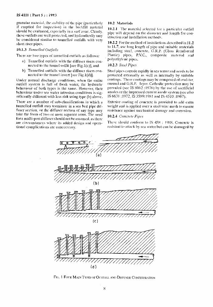
10.1.1 Pi@d O~Jirlls Constrrrctcd Witlrorrl E.rctrvcrlion [see Fig.](a)].
This is an outfall where the pipe and diffuser section is laid enlirely OJJ or above the Xi1 bed. It Jllily k COJI-
strutted in a variety of materials and is placed by the bottom tow, float and sink, or in situ construction methods. The diffuser section is generally a continua- tion of the outfall pipe, with a stepped area reduction, along which circular discharge ports are cut into the pipe. In designing this type of outfall, most careful considration should be given to. its protection against drag from ships’ anchors and trawled fishing gear.
10.1.2 Piped Outfrdls in Trench [see Fig.l(b)]
This is a couunon type of outfall where the pipe is shallowly buried, and in which the diffuser section consists of a number of short riser pipes linked to discharge ports just above the sea bed. Construction techniques are similar to the sea bed type described in 10.1.1, except that the pipe is laid into a pte-dredged or excavated trench which is subsequently backfilled with bed materials, rock or concrete. If backfilled with
7
grallUlilr lllilt~l’i;ll, ihc hlahility c~l‘lhc pip: (p;l~liC!.il;lrl)
if ciiiptied for illspcclion) Iii the backfill illillC~i~ll should be evaluated, especially iu a surfmnr. Clearly. thcsc outfalls arc well ptotccicd, antI hydraulically may be considcrcd similar to lu~uxlled ouifalls with vrry short riser pipes.
10.1.3 Trmrtelled O~~~~i11l.s
a> Tu~~nelled outl;II;S with the dilluser risers ~oII-
netted to the tunnc1 soNit (SW Fig.l(c)], and
1~) Tu~~clletl outfalls with the diffuser risers con- nectcd in the IUIIIIC~ invert [see Fig.l(d)].
Untler lwrlIla1 discharge conditiolls, WIICII ihe entire outl;~ll system is full of fresh waler, the hydraulic behaviour of both tylm is the san~c. Howcvcr, their hehaviour uildcr sea water ililrusioli condilioiis is sig- nificantly different with less risk using typr (17) above.
There arc a ~~Irnber of sub-classirrcatiolIs in which a tuiiiielled outfall inay tcriiiiiiatc in a sea bed pipe dif- fuscr section, or the diffuser section of any type may take the form of two or more separate arms. The nrcd
fora multi-port diffusershould not hc assumed, as thcrc are circun~slaiices whcrc its added dcsigil illid Opril-
lional ~0lllp1i~illi0llS arc ~llllicws:sary.
10.2 iVl;ltrl-ials
10.2.1 The iirateriiil s~iccted ii)r ;I particular outl‘all pipe will depend oil the dialtlctrr and Icllgth f’or con-
StlU~liOll ;lild illStillliitiOll iii~ltlOdS.
10.2.2 For the mcthud ol’irlstallation~ &scribed in 11.2 to 11.7, USC long Icngth of pipe and suitahlc nlatcrials includiiig stccI, concrete, G.R.P. (Was:, Rr:il&on*cd PlilStic) pipes, I?V.CZ., colliposilc Iililtt~riilI ;l:ld
polyclhyl~~le pips.
10.2.3 Sic4 Pipes
Steel pips corrode rapidly iii SCil water and needs to be protcctcd externally ii.5 well ilS internally by suilahle
coatings. Thcsc coatings quay hc co~llposcd ol‘coal-tar, clii~Inel ;IIKI G.R.P. Iaycr. Glthdic protcrtion lllay he provided (SW IS SO62 : 1076) by the use of sacrificial i~~mics or lhr iiuprcsscd current aiiode syslciii (SW crlso IS 6631 :1”)72, IS 35S9:1OSl and IS 4310 :1967).
Exterior coating of’ concrete is provided to add extra
weight and is applird nvcr a steel wire mesh to ensure
resistance against mechanical damagr and corrmion.
10.2.4 Conc~/e Pi,w.v
Thcsc should co~lli~rrn 10 IS 45X : 1 WX. Concrctc is
rcsisklnt 10 attack by SC‘;I water but call he daluaged by
(d)

acids and wastes containing high concentrations of sulphur compounds. Acid resistant cement is used for lining. This should be reinforced and have spigot and socket j6ints. Proper lining at least 150 nun should be applied to protect pipe line from abrasion and impact of waves. Prestressed concrete pipes can also be found advantageous and shall conform to IS 784 :1978.
10.2.5 G.R.F? (Glass Reinforced Plastics) Pipes
These pipes should conform to IS 12709 : 1989. They have advantage of resisting corrosion. but require proper anchorage and additional weight for anchorage and protection against abrasion.
10.2.6 P.V.C. (Polyvenyl Chloride) pipes shall conform to IS 4984 : 1978. These pipes are light weight and requireadditional weightforanchorageandprotec- tion against wave impact, though they provide good resistance against corrosion.
10.2.7 AsbestosCement Pipes
These are alternative material pipes under certain suitable conditions. These should conform to IS 6908 : 1975.
10.2.8 Cotnposite Material
Steel cylinder, reinforced concrete pipes provide good anchorage, enough resistance against waves impact and abrasion. IC is found very suitable for marine en- vironmentifcoated externally bysomesuitablecoating material. These pipes should conform to IS 1916 1963.
11 METHODS OF INSTALLATION
ll.1 C&era1
Anumber of construction methods are available for the installation of niarine outfalls. The method mnst ap- propriate to any given situation should be determined after considering the following:
a>
b)
Length and diameter and the stresses to be im- posed on the outfall arising from pulling, bend- ing, pressure tests, intermediate supports on land and at sea, the forces imposed by waves, currents, water depth and sea bed movement;
Type of internal and external coatings and weight coating, including feasibility ofapplica- tion, particularly at joints, and stresses imposed on coatings;
STRING
C>
4
e)
f)
s> h)
11.1.1
IS 4111 ( Part 5 ) : 1993
Depth of water and the sea bed profile along the proposed outfall route;
Geology of the sea bed and the underlying strata, foundation stability, depth and method of burial (e.g. predredging, post lay trenching, im- ported cover), stability and maintenance of predredged trenches;
General hydrographic regime and physical characteristics of the inshore waters including such factors as currents, waves and tides;
Location and availability of onshore construc- tion areas and facilities;
Contractors, expertise; and
Shipping movement over outfall route and work area, and related problems of anchor dragging and interference with construction method.
The methods of constructing outfalls are basi- cally variations of one or more of the following:
a) bottom pull;
b) lay barge;
c) reel barge;
d) float and lower;
e) sectional outfalls; f) tunnelled outfalls.
Methods (a) to (d) invariably involve constructing the outfall at a location remote from its final position. Temporary stresses imposed in these cases will usually be much greater than those in the permanent condition. With methods (a) to (e), a temporary cofferdam con- struction through beach and foreshore will usually be required for excavation purposes to a point at or below low water, where floating, dredging or trenching equip- ment can be deployed.
11.2 Bottom Pull Method
11.2.1 The bottom pull method (set’ Fig. 2) is the most common method of outfall construction. Typically, pipe strings are assembled on a construction site, in line with the proposed route, and inspected and tested prior to being pulled into the sea.
11.2.2 A barge equipped with heavy duty winches is anchored seaward of the offshore end of the outfall and is used to pull the pipeline from the coistruction site. Successive strings are joined nn until the complete
,- PULLING BARGE
ANCHOR
Frc;. 2 BOTTOM PULL METHOD
9
IS 4111 ( Part 5 ) : 1993
length is in its final position.
11.2.3 This method is usually associated with welded steel pipe which has the advantage of inherent strength and longitudinal flexibility and can have a continuous concrete weight coating for protection and stability. However, prestressed concrete and HDPE or MDPE pipelines have also been installed by this method.
11.2.4 The pulling capacity installed should not be less than the total negative buoyancy of the outfall as designed, for stability in the prevailing wave and cur- rent regime. The temporary pulling stress and the avail- able pulling capacity is a function of the required to be inlinewith theoutfallcanbepulledoutwiththeoutfall.
11.3 Lay Barge Method
The lay barge method (shown in Fig. 3) involves the jointing of pipe lengths on a barge equipped with a launching ramp, down which the pipeline is fed in stages as the barge niovcs progressively away from the shore.
11.3.1 The individual pipes are coated on land and transported to the lay barge in batches, as required. The draft of the barge and the sea conditions determine the distance offshore at which it can ronmencc laying. The rnshorc section is pulled to the land with wincnrs dads then the barge nmves offshore using its own anchors. which are progrcssivcly niovcd oflshorc with lugs.
11.4,1 This method is used for small diameter steel, plastics or flexible anuoured pipelines and, if required, concrete collars can be attached as the pipe enters the water for increased stability.
11.4.2 While purpose built vessels are used for off- shore oil and gas flowlines, small and less sophisticated barges can be. utilized for laying plastics and flexible outfalls in the shallower inshore areas.
11.4.3 This method has particulars application for constructing outfalls to mall coastal towns.
11.5 Float and Lower Method
In sheltered coastal area and inland lakes, outfalls can be floated to the required location and lowered into position (see Fig. 5).
11.5.1 The outfall is assembled onsnore, preterably in one length, at a site that can be remote from the final location. It is then manoeuvred into the water and lifting slings from a number of launch pontoons attached at the required centres. The outfall is raised clear of the sea bed using the winches on the launch pontoons and towed to its required location. The launch pontoons are then anchored and the outfall lowered into
1,s 1111;11 positiou using the winrhcs in :I I)rc-dclcrlllttt~d
,e’(ttK’itc’t’
LAY BARGE ,
11.3.2 This method is associated with laying long lengths of offshore pipelines in an ocean environment, and is nortnal’ly considered to be uneconomical for machine outfalls. However, in sheltered waters, A
simple shallow draft barge can be utilized for laying either steel, HDPE or MDPE outfalls.
11.4 Heel Barge Metllod
The reel barge method of laying submarine pipelines (see Fig. 4). involves coiling a continuous length of pipe onto a large diameter reel or turntable. The pipe is then laid from the barge, through a straightener, and down a ramp on to the sea bed. As the barge progresses along the required route, the reel unwinds a_nd the pipeline is laid in-position.
11.5.2 Steel, PVC and polyethylene outfalls can bc installed by this method. Concrete collars are normally attached to PVC and polyethylene outfalls to provide sufficient weight for stability. But for steel, continuous concrete weight coating or collars can be utilized. For short lengths of outfall in shallow water, it may be feasible to design the line to float without pontoons and to be lowered into position by controlled flooding.
11.6 Sectional Outfall Methods
There are several methods of installing sectional out- fall, the essential feature being that the outfall is built by jointing individual pipes at the sea bed. The procc- dure is heavily dependent upondivers, but is applicable to all types of pipe as littlc or no temporary stress condition is imposed.
10
IS 4111 ( Pal-t 5 ) : 1993
REEL BARGE
AUNCH PONTOONS TOW VESSEL
PIPELINE IN TOW POSITION ADDITIONAL BUOYANCY
IF REQUIRED
11.6.1 At its simplest, conventional small diameter pipes can be laid, one at a time, in a trench on the sea bed or on a suitably prepared granular bed, using a small crane barge and joined together by divers. The joints are normally of the rubbering type, but with additional restraining devices, to prevent the joints opening afler installation.
11.6.2 For larger diameter outfall, say 1 500 nun and above! individual pipes can be lowered to the sea bed from a crane barge of self-elevating platform and sup- ported to in a purpose made fmmework. This framework, which is controlled from the support vessel under the direction of a diver, allows vertical and transverse adjustnlent of the pipe position. By adjusting the longitudinal position, the new pipe can be inserted into the previously laid pipes and the joint conlplcled.
11.6.3 Very large tnultiple outfalls can be installed by the immersed tube method. The outfall is formed from a number of sections which are assenlblcd on a slip- way or in a dry-dock and floated to their required location. Each section is then lowered onto a pre- screeded granular bed or concrete foundation pads. After adjusting its position on the sea bed, an initial seal is made to the preceding secrion using hydraulic rams or hydros- tatic pressure before continuing on to the next section. The final joints between each section are completed from inside the outfall after it has been dewalered.
11.7 Tunnelled Outfalls
Tuiuielled outfall construction is not usually con- sidered for outfalls less than 1 600 Nan diatneter unless:
a) Local physical circunManccs preclude the sea bed outfall previously described; or
b) The movement of the sea bed is so great as to endanger the long-term stability of the outfall.
11.7.1 Submarine tunnels are ideally constructed from a single shaft located on shore and through imperme- able materials such as still homogeneous clays or sound rock. Othcrsea bed materials, faults and fissures can be tunnelled through using modern chenCcal grouting, with or without compressed air, but the cost implica- tions can be considerable.
11.7.2 The tunnel is normally lined with in situ rein- forced concrete or precast concrete segments, to sup- port the excavation and improve the hydraulic characteristics.
11.7.3 At the offshore end, the outfall has to be connected to the sea bed through either a series of vertical shalt or a single shaft from which a diffuser section is laid on the sea bed. These shafts can be formed hy drilling from the sea to the tunnel using a self-elevating platform or floating equipment. Alter- natively, the shafts may be raised from inside the tunnel. finally hreaking out to the sea bed using explosive charges.
12 OPI:,R.~lrl‘ION AND MAINTENANCE
12.1 A IOW sc*a outfall should be designed to operate efficiently \\ ith n~inimum maintenance. Thevelocity in the ouNall sylcn~ should be sufficient to achieve self- cleansing vclocitics to obviate the build up of settled
11

IS 4111 ( Part 5 ) : 1993
particles. A flushing regime should be incorporated in the design to ensure that velocities are sufficiently high to scour the invert of the pipe.
In the normal circumstances, a well designed outfall should give satisfactory service without routine atten- tion. Evidence of a build-up of sediment within the outfall may be observed by increases in the head re- quired to maintain discharge at a given tidal state. If there is a marked decrease in the retention period in the outfall at a given rate of flow, the installation should be monitored regularly as regards hydraulic performance. Physical checks should be made regularly at 6 to 12 month intervals over the first 2 or 3 years of an outfall’s life, and every 2 or 3 years thereafter.
12.2 The full route of the pipe should be inspected by engineering divers to note any signs of damage or other unsatisfactory conditions. Particular attention should be given to the following: \
a) Abrasion of the outer protective coating; b) Undermining of the bed by erosion of bed
materials;
c) Excessive growths of marine organisms; and
d) The conditions of the outlet ports.
12.3 The report should describe any remedial work required and this should be carried out at the earliest opportunity before the nostilc environment further attacks the outfall fabric.
IS No.
458 : 1988
784 : 1978
1916: 1963
2490 (Part 1) : 1981
2951 : 1965
(Part 1) : 1965
(Part 2) : 1965
3589: 1981
4310: 1967
4984 : 1987
ANNEX A ( Clause 2.1 )
LIST OF STANDARDS REFERRED
Title IS No.
Precast concrete pipes (with or 5600 : 1970 without reinforcement)
Prestressed concrete pipe (in- 6631 : 1972 eluding fittings) (first revision)
Steel cylinder reinforced con- 6908 : 1975 Crete pipes
Tolerance limit5 for industrial effluents discharged into inland 8062 : 1976 surface waters : Part 1 General limits (second revision)
Recommendations for estima- (Part 1) : 1976
tion of flow of liquids in closed conduits :
(Part 2) : 1976 Uhderground pipelines
Head loss in straight pipes due to (Part 3) : 1977 friction resistance
Head loss in valves and fittings (Part 4) : 1979
Electrically welded steel pipes for water, gas and sewage 11625 : 1986
Weldable steel pipe tittings for marine purposes 11639 (Part 1) :
High density polyethylene pipes 1 19s6 for potable water supplies; sewage and industrial effluents 12709: 1989 (third revision)
Title
Sewage and drainage pumps
Steel pipes for hydraulic pur- poses
Asbestos cement pipes and pipe fittings for sewerage and drainage
Code of practice for cathodic protection of steel structures :
General principles
Ship’s hull
Galvanic protection of dock- gates, caissons, piers and jetties
Criteria for hydraulic design of penstocks
Criteria for structural design of penstocks : Part 1 Surface penstocks
GRP pipes for water supply and sewerage
12

Standard Mark The use of the Standard Mark is governed by the provisions of the Bureau qf Indian
Standards Act, 2986 and the Rules and Regulations made thereunder. The Standard Mark on products covered by an Indian Standard conveys the assurance that they have been produced to comply with the requirements of that standard under a well defined system of inspection, testing and quality control which is devised and supervised by BIS and operated by the producer. Standard marked products are also continuously checked by BIS for con- formity to that standard as a further safeguard. Details of conditions under which a licence for the use of the Standard Mark may be granted to manufacturers or producers may be obtained from the Bureau of Indian Standards.

Bureau of Indian Standards
BIS is a statutory institution established under the Bureau of Indian Standards Act, I986 to promote harmonious development of the activities of standardization, marking and quality certification of goods and attending to connected matters in the country,
Copyright
BIS has the copyright of all its publications. No part of these publications may be reproduced in any form without the prior permission in writing of BIS. This does not preclude the free use, in the course of implementing the standard, of necessary details, such as symbols and sizes, type or grade designations. Enquiries relating to copyright be addressed to the Director ( Publications ), BIS.
Review of Indian Standards
Amendments are issued to standards as the need arises on the basis of comments. Standards are any reviewed periodically; a standard along with amendments is reaffirmed when such review indicates that no changes are needed; if the review indicates that changes are needed, it is taken up for revision. Users of Indian Standards should ascertain that ,they are in possession of the latest amendments or edition by referring to the latest issue of ‘BIS Handbook’ and ‘Standards Monthly Additions’. Comments on this Indian Standard may be sent to BIS giving the following reference:
Dot : No. CED 24 ( 3018 )
Amendments Issued Since Publication
Amend No. Date of Issue Text Affected
BUREAU OF INDIAN STANDARDS
Headquarters:
Manak Bhavan, 9 Bahadur Shah Zafar Marg, New Delhi 110002 Telephones : 331 01 31, 331 13 75
Regional Offices :
Central : Manak Bhavan, 9 Bahadur Shah Zafar Marg NEW DELHI 110002
Eastern : l/ 14 C. I. T. Scheme VII M, V. I. P. Road, Maniktola CALCUTTA 700054
Northern : SC0 445-446, Sector 35-C, CHANDIGARH 160036
Telegrams : Manaksanstha ( Common to all offices )
Telephone
I
331 01 31 331 13 75
1
37 84 99, 37 85 61 37 86 26, 37 86 62
I
53 38 43, 53 16 40 53 23 84
Southern : C. I. T. Campus, IV Cross Road, MADRAS 600113 I
235 02 16, 235 04 42 235 15 19, 235 23 15
Western : Manakalaya, E9 MIDC, Marol, Andheri ( East ) BOMBAY 400093
632 92 95, 632 78 58 632 78 91, 632 78 92
Branches : AHMADABAD. BANGALORE. BHOPAL. BHUBANESHWAR. COIMBATORE. FARIDABAD. GHAZTABAD. GUWAHATT. HYDERABAD. JAIPUR. KANPUR. LUCKNOW. PATNA. THTRIJVANANTFTAPURAM.
Prlnted at New India PrintI- Press, Khorja. India