Embed Size (px)
Citation preview

Disclosure to Promote the Right To Information
Whereas the Parliament of India has set out to provide a practical regime of right to information for citizens to secure access to information under the control of public authorities, in order to promote transparency and accountability in the working of every public authority, and whereas the attached publication of the Bureau of Indian Standards is of particular interest to the public, particularly disadvantaged communities and those engaged in the pursuit of education and knowledge, the attached public safety standard is made available to promote the timely dissemination of this information in an accurate manner to the public.
इंटरनेट मानक
“!ान $ एक न' भारत का +नम-ण”Satyanarayan Gangaram Pitroda
“Invent a New India Using Knowledge”
“प0रा1 को छोड न' 5 तरफ”Jawaharlal Nehru
“Step Out From the Old to the New”
“जान1 का अ+धकार, जी1 का अ+धकार”Mazdoor Kisan Shakti Sangathan
“The Right to Information, The Right to Live”
“!ान एक ऐसा खजाना > जो कभी च0राया नहB जा सकता है”Bhartṛhari—Nītiśatakam
“Knowledge is such a treasure which cannot be stolen”
“Invent a New India Using Knowledge”
है”ह”ह
IS 3382 (1965): Stainless Steel Milk Pipes and Fittings[FAD 19: Dairy Products and Equipment]


IS : 3382 - 1965
lndian Standard SPECIF;CATION FOR
STAINLESS STEEL MILK PIPES AND -FITTINGS
Dairy Industry
Chairman
DR K. C. SEN
Sectional Committee, AFDC 12
Rt?prerenfing
Indian Dairy Science Association, Bangalore
Members
A~RNXJLTURAI. MARKETING A~vrsm TO THE GOVERNMENT OF INLXA
SHRI R. K. MALIK (Allmate)
SHRI B. R. BEDEKAR SHRI I. C. E. Dabson (Alfcmafe)
SHRI c. v. CHANDRA SEKHAR
SHRI S. S. MANI (Alternate)
Sinr H. M. DALAVA
Dn ,J. D. CONTRACTOR (Alfernafe) SHRI C. D. Dhs~oon
Snm H. W. Ramchandani (Alternate) DIRECTOR
AW~TANT DIRECTOR, MILITARY FARMS, (PLANNING) (Alfernafc)
EXECUTIVE HEALTH OFFICER MUNICIPAL ANALYST (Alternate)
COL A. G. FERNAXDES
Lr-COL N. G. C. IENOAR (Alfemale) Sxnr G. S. GODBOLE
SHRI Y. V. SALPEKAR (Alternate) DR K. K. IYA
Dn N. N. DASTUR (Alferaafr) SHRI A. R. A. KRCWNAN
SHRI K. P. SIWX (Alfernnfe) COL M. N. KUNZRU
Dn S. S. PHATAK (Alfmafe) M,LK COMMISSIONER SHRI S. N. MITRA SHRI B. K. MURTHY
SH~I N. GOPAL. KRISRNAN (Alfernafe) SHRI E. E. NAEGELI
SHRI F. J. RYAN (Alfernnfe) SHRI J. PADMANABHAN
SHRI J. G. BROWN (Alternate) SHRI V. G. RAJADHYAKSHA
Dn A. P. MAHADEVAN (Alternate) SHRI S. RAMA~WAMY SHRI V. H. SHAH
SHRI A. JENSEN (Alfernnle) Dn R. S. SR~VA~TAVA
SHRI P. JANARDANA AIYAR (Alternate) - __^
Directorate of Marketiqg & Inspection (Ministry of Food & Agriculture), Nagpur
Hindustan Milkfood Manufacturers’ Limited, Nabha
T.T. (Private) Limited, Bangalore
Kairx$trict Co-operative Milk Producers’ Union Ltd,
Larsen & Toubro Ltd, Bombay
Directorate of Military Farms, Army Headquarters
Municipal Corporation, Bombay
F$d Inspection Organization, Quartermaster General’s Branch, Army Headquarters
Dairy Development Commissioner, Government of Mabarashtra
National Dairy Research Institute, Karnal r . .
Defence Production Organization [Ministry of Ddftice (DGI)]
Technical Standardization Committee (Foodstuffs) (Ministry of Food & Agriculture)
Milk Commissioner, Madras Central Food Laboratory, Calctitta Indian Aluminium Co Ltd, Calcutta
Nestle’s Products (India) Ltd, New Delhi
The A.P.V. Engineering Co Ltd, Calcutta
Hindustan Lever Ltd, Bombay
Directorate General of Technical Development Vulcan Trading Co Ltd, Bombay
Central Committee for Food Standards (Ministry of Health)
Central Food Technological Research Institute (CSIR), Mysore. ,\ UR M. bWAMlNATHAN
S~nr M. R. CHANDRASEKHARA (Alfernaw
(Continued on page 2)
. INDIAN STANDARDS INSTITUTION MANAK BHAVAN, 9 BAHADUR SHAH ZAFAR MARG
NEW DELHI 1

IS : 3382 - 1965
(Continuedj%m page 1)
Members Reprerenling
SHRI R. H. VARIAVA SHIU B. P. PALKHIWALLA (A1lernace)
P&on Limited,*Bombay
SHnr H. c. VERMA Ministry- of Food & Agriculture SHRI S. N. MOHAN (Alternate)
DR I. S. VERMA Dadrirr~~hnology Division, National Dairy Research Institute,
SHR~ M. R. SRINIVASAN (Al&wale) SHnr James N. Warner in personal capacitv (Allakebod Aqri~chral Inrtitule, Allakohad) SHRI P. H. RAMANATHAN,, Director, ISI (Ex-ofi& Member)
Assistant Director (Agn & Food) (Secretary)
Associate Secr~&ry
SHRI M. G. KRISHNA Rno, Assistant Director (Ens, ISI)
Dairy Equipment Subcommittee, AFDC 12 : 1
SHRI A. R. A. KRI~HNAN
Members
SHRI K. P. SINCH (Allarnatc t‘ Shri A. R. A. Krishnan)
SHRI C. G. AMIN SHRI B. C. BACCHI SHRI c. v. CHANDR.4 SEKHAR SH~I H. M. DALAYA
DR J. D. CONTRACTOR (Alternate) DIRECTOR DIItECTCJR SHRI G. S. GODBOLE
- Dn A. P. DESHMUKH (Alhzafe) MILK COMMISSIONER SHRI A. K. Mrrr~n SHRI A. L. Morgan
SHRI A. BASU (Al&mlc) SHRI A. B. MULLICK S~nr B. K. MURTHY
SHRI N. GOPAL KIUSHNAN (ANmale) SHRI J. PADMANABHAN
SHRI J. G. BROWN (Altemate) SHRI H. W. RAMCHANDA~~ SHRI H. K. SHAH
SHRI P: K. AMBANI (Ahnate) SHRI V. H
SHRI 1 ” Snnr R. H. VA~ZAVA‘
SHRI B. P. PALKHIWALLA (Alternafe) SHRl H. c. VERMA
&in: S. N. MOHAN (Alternate) SHRI JAMES N. WARNER
Defence Production Organization [Ministry of Defe”ce (DGI)]
Alembic Glass Industries Ltd,, Baroda National Dairy Research Institute, Karnal T.T. (Private) Limited, Bangalore KadrnanIt Co-operative Milk Producers’ Union Limited,
Directorate of Military Farms, Army Headquarters Alfa-Lava1 Private Ltd, Bombay Dairy Development Commissioner, Government of Maharashtra
Milk Commissioner, Madras Milk Commissioner, West Bengal The Alumininm Manufacturing Co Private Ltd, Calcutta
Directorate General of Technical Development Indian Aluminium Co Ltd, Calcutta
The A.P.V. Engineering Co Limited, Ca!cutta
Larsen & Toubro Ltd. Bombay Jeewanlal (1929) Ltd, Calcutta
Vulcan Trading Co Ltd, Bombay
P&on Limited, Bombay
Ministry of Food & Agriculture
In personal capacity (Allafrabod Agricult~rral Inctitule, Allakabad)
2

IS : 3302 - 1965
Indian Standard
SPECIFICATION FOR
STAINLESS STEEL MILK PIPES AND FITTINGS
0. FOREWORD
0.1 This Indian Standard was adopted by the Indian Standards Institution on 11 August 1965, after the draft finalized by the Dairy Industry Sectional Committee had been approved by the Agricultural and Food Products Division Council.
0.2 This standard has been prepared on .the basis of the International Dairy Federation Standard FIL-IDF 14 : 1960 ‘Milk pipe fittings’. The International Dairy Federation Standard is inch based, though their metric equivalents have also been given therein side by side. However, in this standard the dimensions have been given only in metric values a.s given in the International Dairy Federation Standard.
0.3 These pipes and fittings can also be used in other food processing industries if the material specified in 2.1 does not chemically react with food to be processed.
0.4 The expanding instructions for stainless steel pipe fittings given in Appendix A are intended as a guide for the expanding operations.
0.5 For the purpose of deciding whether a particular, requirement of this standard is complied with, the final value, observed or calculated, express- ing the result of a test shall be rounded off in accordance with IS : 2-1960”. The number of significant places retained in the rounded off value should be the same as that of the specified value in this standard.
1. SCOPE
1.1 This standard prescribes the requirements for milk pipes and milk pipe fittings made of stainless steel for use in the dairy industry. The pipe fittings and components are of two types suitable either for welding to the tube or for attachment to the tube by expanding.
*Rules for rounding off numerical values (revised).
3
. .

IS : 3382 - 1965
2. PIPING
2.1 Material - The pipes shall be made of stainless steel of com- position corresponding to Designation 04Cr 19Ni9 or 04Cr 19Ni9Ti20 or 05Cr18NillM03 of IS : 1570-1961”.
2.1.1 The pipes shall be cold-drawn seamless tubes or welded and drawn tubes. They shall be softened, descaled and pickled; polished internally or externally or on both sides, as required.
2.2 Outside Diameter
2.2.1 The outside diameter of the stainless steel pipes shall be the following :
25.4 mm 38.1 mm 50.8 mm 63.5 mm 76.2 mm
2.2.1.1 The tolerances for pipes shall be as agreed to between the manufacturer and the purchaser.
2.2.2 Freedom from Defects-The pipe shall be clean, smooth and free from surface defects or longitudinal grooving internally and externally. The pipes shall be straight, cylindrical and of uniform thickness.
3. FITTINGS
3.1 Mqterial -All the components of the range of fittings, except for the seal (see 3.6), shall be made of stainless steel of composition correspond- ing to Designation 04Cr19Ni9 or 04Cr19Ni9Ti20 or 05Crl8Nil lM03 of IS : 1570-1961*.
3.2 Male Parts, Liner, Nut and Seal
3.2.1 Expanded Type Male Part and Liner
3.2.1.1 The expanded type male part shall be as shown in Fig. 1.
3.2.1.2 The expanded type liner shall be as shown in Fig. 2.
3.2.1.3 Both these components shall be suitably grooved internally to give adequate strength in attaching to the tube. A satisfactory grooving is illustrated in Fig. 3.
3.2.1.4 For external thread see 3.5.1.
- 3.2.2 Welded Type Male Part and Liner
3.2.2.1 The welded type male part shall be as shown in Fig. 4.
*Schedules for wrought steels for general engineering purposes.
4

IS : 3382 - 1965
3.2.2.2 The welded type liner (short liner) shall be as shown in Fig. 5.
3.2.2.3 For external thread see 3.5.1.
3.3 Nut
3.3.1 The nut shall be as shown in Fig. 6.
3.3.2 It shall be noted that dimensions are given for a standard form of hexagonal nut but any other external shape such as a castellated or round form may be adopted, if desired, as this does not affect the operation of the standard union.
3.3.3 For internal thread see 3.5.1.
3.4 Spanner - A suitable spanner for an hexagonal type of nut shall be as shown in Fig. 7.
3.5 External Thread (of Both Expanded and Welded Types) and Internal Thread
3.5.1 The thread shall be made in accordance with Fig. 8 and Fig. 9.
3.6 Seal
3.6.1 The seal which shall be moulded from a suitable grade of rubber of approximately 85” International rubber hardness shall be as shown in Fig. 10.
3.7 Bends and Tees
3.7.1 Expanded Tyie Bends and Tees - The expanded type bends shall conform to Fig. 11 and the expanded type tees shall conform to Fig. 12.
3.7.2 Welded Type Bends and Tees - The welded type bend shall be as shown in Fig. 13 and the welded type tee shall be as shown in Fig. 14.
NOTE 1 -The dimensions of the bodies of the bends and tees differ according to whether the fittings are to be attached by welding or by expanding, but in either case the length between one face and the centre line of the opposite fitting is the same.
NOTE 2 - The distance between one face and the centre line of the branch is exactly the same as the dimension of the bend and the total length of the tee is double that of the bend. The radius of the bends has not been specified.
3.8 All milk contact surfaces shall be polished by emery not coarser than 220 grit of IS : 715-1962”.
4. EXPANDING OPERATIONS ‘AND TOOLS
4.1 The instructions regarding expanding operations and the necessary tools given in Appendix A are typical and for information only.
*Specification for coated abrasives, glue bond (revised).
5

F IS : 3382 - 1965
i APPENDIX A
(Clause 4.1)
INSTRUCTIONS FOR’ EXPANDING STRAIGHT PIPE OF 254 mm AND 51.8 mm DIAMETER AND 1.25 mm
THICKNESS, AND 63 mm AND 76.2 mm DIAMETER AND 1.5 mm THICKNESS
A-l. TOOLS
A-l.1 A set of tools (see Fig. 19) consists of:
4 b) c) 4 e) f 1 9) h) 3
Base plate,
Torque wrench and sockets,
Clamp block (see Fig. 20),
Expander (see Fig. 21))
Split cutting ring (see Fig. 22),
Expander rollers (see Fig. 23),
Spigot locating ring and levers (see Fig. 24),
Pilot bush assembly (see Fig. 25 to 34), and
Spherical hexagonal head adaptor (see Fig. 35).
Hacksaw frame, suitable hacksaw blades, spanners for clamp block nuts, file, heavy duty electric drill 8.0 mm capacity and 1400-2600 rev/min complete with sleeve and disc pad, are also required.
A-2. PROCEDURE-LINERS AND MALE PARTS
A-2.1 preparation -- Bolt base plate to bench. Secure to base plate a clamp block of size required, counterbore for fitting towards front. If long lengths of tube are to be used, fit an adequate support to keep the tube level.
A-2.2 Cutting the Tube (See Fig. 15)
A-2.2.1 Length Required - Length required will be the distance between the two fittings to be connected, less 6.4 mm (twice the distance between the faces of the counterbore of a seal ring).
A-2.2.2 Mark tube to length required; when a liner is to be expanded, place nut, facing correctly, on tube. Slide tube through centre hole of clamp block. Fit split cutting ring in clamp block. Line up cutting mark on tube with face of cutting ring. Tighten clamp block.
NOTE - The ends of polished tube tend to be tapered; cut off tapered portion before marking off tube to length.
6

IS : 3382 - 1965
A-2.2.3 Cut tube with hacksaw. File end square against cutting-off ring. Remove ring.
A-2.3 Expanding (See Fig. 16)
A-2.3.1 Slide fitting over tube, spigot facing end of tube. Loosen clamp block and position fitting in its counterbore.
A-2.3.2 Adjust tube flush with spigot face, and then tighten clamp block. Check that the tube does not fall below the face of the spigot at any point.
A-2.3.3 Place spigot locating ring over spigot on fitting.
A-2.3.4 Insert expander through ring into tube.
NOTE - The expander rollers are to be lightly oiIed and never used dry.
A-2.3.5 Set torque wrench to correct figure for tube size as specified in the following table. Apply wrench and rotate expander in a clockwise direction until wrench collapses :
Liner ad Male Part Size Torque Wrench Setting
mm m.kgf
25.4 2.8
38.1 4.8
50.8 9.0
63.5 13.1
76,2 16.6
A-2.3.6 Release expander by opposite rotation.
A-2.3.7 Remove expander and spigot locating ring with levers supplied.
A-2.4 Facing-Off (see Fig. 17 and 18)
A-2.4.1 Insert pilot bush assembly into tube until large knurled sleeve is against face of fitting.
A-2.4.2 Hold knurled sleeve and rotate key in a clockwise direction until segment jaws grip. Using tube supplied on key handle, tighten grip.
A-2.4.3 Remove sleeve and key as one unit.
NOTE - The 25.4 mm size key has no handles and is only knurled.
A-2.4.4 Check that spindle is square with face of fitting.
A-2.4.5 Place 80 grit Abradisc on face of disc sleeve pad.
A-2.4.6 Lightly oiI spindIe projecting from tube, and slide disc sleeve on it. Rotate by hand to check freedom of movement.
A-2.4.7 Fit spherical hexagon head adaptor into chuck of power unit. Insert spherical hexagon head into disc sleeve and start power unit. Apply
7

IS : 3382 - 1965 7
light pressure only to face of fitting in order to avoid overheating of Abradisc and motor. Always start and stop motor with hexagon head in contact with disc sleeve.
A-2.4.8 When the end of the tube has been ground back to the face of the fitting, replace the 80 grit with a 120 grit Abradisc and smooth off the faces of fitting and tube, removing as little as possible.
A-2.4.9 Release pilot bush assembly by means of knurled sleeve and key.
A-2.4.10 Clean off burrs and sharp edges.
A-2.4.11 Check that seal ring will fit over spigot and make a joint on face of tube, leaving at least 0.4 mm gap between steel ring and the back face of its spigot to allow for compression of the rubber.
A-2.4.12 Release clamp block and remove work.
8

IS:338211985
ACME THREADS (FOR
CHAMFER DETAILS SEE FIG. 8)
-GROOVE!
-E-
*CHAMFER 0.25 x 450
t DETAILS OF GROOVES SEE FIG. 3
------,----- 50.8
/__--__l_____,.____ -__ 64.160 64,059 j 56.0
-_____-___ 1 63.5 , 77.673 , 77.572 ( 69.0 i 63.5 69.7 25.0
I--____--
I 76.2 1 91.186 I 91.084 i --~---- ----- 1.00;
82.0 1’ 76.3 82.3 30.0 /
*See IS, : 919-1963 Recommendation for liiits and fits for engineering (reuised).
NOTE - Sizes corresponding to 38.1 mm and 50.8 mm only, are reversible on tube. For other sizes, the 3 mm deep locating spigot for seal to face end of tube.
All dimensions in millimetres.
FIG. 1 DIMENSIONS FOR EXPANDED TYPE MALE PART
9

IS : 3382 - 1965
t
\ GROOVES
m-CHAMFER I x45O
SHARP EDGE
DETAILS OF GROOVES SEE FIG.3
OUTER DIAMETER OF PIPES hlO* 1 h;’ ~
A- C ~ D DlO* ,
~ E hlO*
___--- _---_‘--_ __,___ _____ -- -----
25.4 33.8 ’ 29.5 ~ 25.5 i 29.0 17.0 ___----- __----___
38.1 47.0 42.5 38.2 1 42.5 -----___ ___~ ___I_- ___-__ ___--_ 20.0
50.8 ,60.5 , 56.0 ; 51.0 56.0 ’ ---- -_------ __--I___- ----‘-p-__
63.5 74.0 / 69.0 ; 63.5 69.7 25.0 _____~______ ___~_,___~_ __-_-_ ______
76.2 87.5 1 82.0 i 76.3 82.3 30.0
*See IS : 919-1963 Recommendation for limits and fits for engineering (revised).
NOTE - For all sizes, the 3 mm deep locating spigot for seal to face end of tube.
All dimensions in millimetres.
FIG. 2 DIMENSIONS FOR EXPANDED TYPE LINER
10

IS : 3382 - 1965
/--&NO. OF GROOVES V-SHAPE 0*25mm DEEP
> THREADED FORM PARALLEL GROOVES lmm PITCH. DIAMETER OVER TIPS SHOULD NOT EXCEED
‘c’ DIA
OUTER DIAMETER
No. OF ~ GROOVES
I
OF PIPES A B c I
25.4 9.0 25.5 1 -
38.1
- 12.0 6
I- 38.2 i
50.8 ) 51.0 ,--------
63.5 17.0 63.5 ~-
76.2 ~ I-_---
22.0 10 ~ 76.3 ~
All dimensions in millimetres.
FIG. 3 DIMENSIONS FOR GROOVES FOR EXPANDED TYPE FITTINGS

IS : 3362 - 1965
RH ACME THREADS (FOR DETAIIS SEE FIG.
---
OUTER A B C I D DIAMETER hlO* OF PIPES MaX Min
25.4 37.186 37.084 ~ 29.2 ~ 23.0 25.9
38.1 50648 50.546 ~ 42.7 ~ 35.5 1 38.4
50.8 64.160 64.059 1 56.2 ~ 48.5 / 51.4
! 63.5 77.673 76.572 ~ 69.9 / 60.5 i 63.9
I 76.2 91.186 91.084 ~ 82.6 ~ 73.0 I 76.4
*See IS : 919-1963 Recommendation for limits and fits for engineering (revised). ~____
All dimensions in millimetres.
FIG. 4 DIMENSIONS FOR WELDED TYPE MALE PART

“? I
>
j
IS : 3382 - 1965
rCHAMFER 0.25 x 450
3*000 i9070 -I
me-
w - 4-L 4
D-12 -3
OUTER DIAMETER A B OF PIPES hll* i hlO*
1 C ) D i
25.4 ~ 33.8 29.2 23.0 -/ 25.9
38.1 1 47.0 I 42.7 ! 35.5 I 38.4
50.8 60.5 I 56.2 1 48.5 i 51.4 1
69.9 1 60.5 1 63.9
82.6 1 73.0 1 76.4
*See IS : 919-1963 Recommendation for limits and fits for engineering (revised).
All dimensions in millimetres.
FIG. 5 DIMENSIONS FOR WELDED TYPE SHORT LINER
13

IS : 3362 - 1965
RH ACME THREADS DETAILS SEE F10.9)
-C A/F---d
I 25.4 ! 38.125 38.049 ’ 30.5 ~ 46.0 I
‘---------- --
38.1 1 51.638 1 51.537 43.5 I 61.0 ~
I-p------- 50.8 j 65.151 65.049 57.0 76.0 1
63.5 ( 78.664 78.562 70.0 ~ 91.0 ~ ____-I -v
76.2 ( 92.177 i 92.075 83.0 106.5 I Lo--_- .~
*See IS : 919-1963 Recommendation for limits and fits for engineering (revised).
All dimensions in millimetres.
FIG. 6 DIMENSIONS FOR HEXAGON NUT
14

IS : 3362.1965
k------A------d.
A I
C .-------A- _-----_- ‘T I
-OUTER DIAMETER ) A B OF PIPES
c i I
25.4 248 : 46.9 102 j
, 38.1 286 62.2 124 /
50.8 305 77.5 149 ___--- __---
63.5 337 92.8 ( 162
I 76.2 365 108.6 I 175 j _ .____~_
All dimensions in millimetres.
FIG. 7 DIMENSIONS FOR SPANNER FOR HEXAGON NUT
15

.’
I!$ : 3382 - 1965
AI
I OUTER A, A, -~ I
DIAMETER ___ OF PIPES Max 1 Min 1 -1 Max j Min ,
25.4 37.186 37.084 1 35.357 j 35.255 (
38.1 50.648 50.546 1 48.819 I 48.717 -1
50.8 I 64.160 64.059 1 62.332 / 62.230 i
All dimensions in millimetres.
FIG. 8 DIMENSIONS FOR EXTERNAL THREADS

IS: 3382-1965
OUTER DIAMETER OF PIPES
25.4
38.1
50.8
63.5
76.2
Al A*
Max Min Max Min
38.024 36.017 38.125 35.916
51.638 51.537 49.530 49.428 i
65.151 65.049 63.043 62.941
78.664 78.562 76.556 76.454
92.177 92.075 90-068 I 89.967 I
All dimensions in millimetres.
FIG. 9 DIMENSIONS FOR INTERNAL THREADS
17
i ,+

IS : 3382 - 1965
.
3*OO?‘O .oo
7*00*40
25.4 j 32.50 1 28.80 / 23.00 25.50
---- 3% 1 46.00 i 42.30 j 35.50 / 38.00 ‘-
50.8 59.50 j 55.80 ) 48.50 ) 51*00
/ 63.5 i 73.00 ] 69.50 / 60.50 1 63.00 -1
I 76.2 86.50 82.10 I 73.00 ’ 75.50
All dimensions in millimetres.
FIG. 10 DIMENSIONS FOR SEAL RING
18

ISr338!2-1965
OUTER DIAMETER
c D OF PIPES / 21 _I ". j 1 1
25.4 55 k2.0 5.0 j -PI 1
38.1 ~ ;i 1’25 50.8
1 , 24.5 1 4.5
63.5 I
lb5 *I 5.0 76.2 ! 110
NOTE - Dimension A will remain constant for each appropriate size of bend irres- pective of which combination of fittings are expanded to the ends.
All dimensions in millimetres.
FIG. 11 DIMENSIONS FOR EXPANDED TYPE BEND

IS : 3382 - 1965
I
.’
,
OUTER DIAMETER
I B I
OF PIPES fl /
25.4* 55
3% 1 70 1.25
50.8 I *? I 63.5 105 I
1.50 ‘ 76.2 ~ 110 /
*Male parts only may be fitted on ends of tee corresponding to this size.
NOTE - Dimension A will remain constant for each appropriate size of tee irrespec- tive of which combiRation of fittings are expanded to the ends.
All dimensions in millimetres.
FIG. 12 DIMENSIONS FOR EXPANDED TYPE TEE
20

/ OUTER DIAMETER i :I
.B I
OF PIPES -__
I 25.4 i 55 ~ __--
38.1 70 1.25 ~
50.8 I 82 ~
63.5 1 105 i
I 1.50 1
I 76.2 110
NOTE -Dimension A will remain constant for each appropriate size of bend irrespective of which combination of fittings are welded to the ends.
All dimensions in millimetres.
FIG. 13 DIMENSIONS FOR WELDED TYPE BEND
21
I _ i

IS : 3382-1965
j OUTERDIAMETER A B OF PIPES I*1
1 ---
1.25
1 63.5 ,105 1.50
76.2 110
*Male parts only may be fitted on pnds of tee corresponding to this size.
NOTE -Dimension A will remain constant for each appropriate size of tee irres- pective of which combination of fittings are welded to the ends.
All dimensions in millimetres.
FIG. 14 DIMENSIONS FOR WELDED TYPE TEE
22

IS : 3382 - 1965
REGISTER FOR
FIG. 15 OPERATIONS A-2.2.2 AND A-2.2.3 (As FOR LlNERj REVERSE CLAMPING BLOCK WHEN EXPANDING MALE PART
SPbGOT LOCATING
FIG. 16 OPERATIONS A-2.3.1 TO A-2.3.7
23

IS : 3382 - 1965
PILOT BUSH ASSEMBLY-,
KNURLED SLEEVE
FIG. 17 OPERATIONS A-2.4.1 TO A-2.4.4
/- PAD AND ABRADISC
FIG. 18 OPERATIONS A-2.4.5 TO A-2.4.12
24

; :.,
I IS : 3302 - 1965
‘i J
CLAMPING BLOCK EXPANDED
SPIGOT LOCATING
REGISTER FO
SPIGOT LOCATING
FIG. 19 EXPANDING TOOL ASSEMBLY
25

IS : 3382 - 1965
SECTION XX
_- OUTEE~D;;~~ / A B‘ c
/ Max Min I Max Min ~ Max Min
25.4 1 37.211 37.186 29.520 , 29.495 ( 33.805 33.780 ; --,
‘- 38.1 __-L-- --
/ 50.673 50.648 i 42.522 42.497 ~ 47.015 46.990 ---~
50.8 1 64.188 64.l63 ~ 56.007 /_____~_
55.982 ~ 60.501 60.476 ~ --8
63.5 / 77.700 77.675 ( 69.013 ,’ 68.998 i 74.025 74.000 (
l- 76.2 1 91.215 91.190 ~ 82.016 81.991 I 87.510 87.485
All dimensions in millimetres.
FIG. 20 DIMENSIONS FOR CLAMP BLOCK SUB ASSEMBLY

IS : 3382 - 1965
TOTAL EXPANSION oi= ROLLERS TO CENTRE OF
FITTINGS- E (b -
I OUTER A B iC ~ D' iE
NO.OF 1 ROLLERS
DIAMETER REQUIRED 1 OF PIPES / PER ,
ASSEMBLY 1
25.4 138.112 13.540 1 8.764 ( 21.084 ( 20.957 I 24.384
--- 38.1 1 146.050 ixi 15.041 )=i 33.964 ~ 37.692 3 ‘-1
50.8 146.050 22.860 j 17.831 / 46.791 / 46.664 I 49.958
All dimensions in millimetres.
FIG. 21 DIMENSIONS FOR EXPANDER AND FITTINGS SUB ASSEMBLY
27

IS : 3382 - 1965
OUTER
I DIAMETER OF PIPES
25.4 25.4 1 37.131 37.106 29.495 29.460 33.780 ) 33.755 / ) / , ~~___ ______ -8
38.1 38 .
j 50.648 50.623 42.497 42.472 ~ 46.990 1 46.965 -- _‘- -----pi--------
50.8 51 1 64.163 64.138 / 55.982 ’ 55.957 1 60.476 60.451
I 63.5 / 63.5
i- 76.2 1 76 j 91.190 91.165 t 81:991 81.966 ( 87.485 ( 87.460
NOTE - To be hardened.
All dimensions in millimetres.
FIG. 22 DIMENSIONS FOR SPLIT CUTTING RINGS
I
28

IS : 3382 ; 1965
_____ i OUTER DIAMETER I A I B c D oc
OF PIPES
,_--- Max ~ Min
1 _-______~~______-_ ____-
25.4 6.325 1 5.556 j 31.353 , 0.203 0.178
38.1 _-_-J 9.500 1 8.731 I 1” 28.575 ;
50.8 14.732 1 13.919 ) --.-J I o’508 o’381
--_I, 63.5 I 14.960 ) 23.416 ) ~
I
0”52&’ / ‘_
15621 I-__
’ 76.2 15.240 ( 18.256 , O”26’
NOTE - 1 Rollers are hardened, ground and polished.
NOTE - 2 All sharp corners to be removed.
/
I
FIG. 23 DIMENSIONS FOR ROLLERS FOR EXPANDING TOOLS
I
29

OUTER A ~ B :~ c , DIAMETER
OF PIPES i Max. ’ Min
D E F G
Max ’ Min MUX Min __-~- --- _______
25.4 ( 69.85 ! 52.388 ! 29.069 29.043 24.257 24.105 50.80 20.752 20.498 25.8 I I_- __- ------ ,~_~
38.1 ’ 73.02 ( 65.086 I 42.635 ; 42.610 36.957 36.805 63.50 37.3 I ~ -___ 19.177 .18.923 ‘----
50.8 1 85.72 j 77.786 / 56.069 1 56.043 49.657 I 49.505 ’ .76.20 ) ~ 50.0
_‘-_- I ’ 63.5 1 98.42 / 90.486 1 69.835 ~ 69.810 61.796 ; 61.644 i 88.90 , 14.811 1 14.557 62.3
I I___ ‘~&.-.-.U ~ 76.2 / 111.12 ! 82.510 74.496 74.344 111.12 9.652 j 9.398 1 75.0
NOTE - To be hardened.
All dimensions in millimetres. ,
FIG. 24 DIMENSIONS FOR SPIGOT LOCATING RINGS

i
I
.52 DIA x 95.25 LONG SILVER STEEL PIN SHRUNK OR PRESS FIT IN TAPERED MANDREL. CENTRE LINE OF PIN PARALLEL TO MANDREL AXIS
‘1
All dim&ions in millimetres.
FIG. 25 DIMENSIONS FOR TAPERED MANDREL (PILOT EXPANDING BUSH FOR FACING 25.4 mm EXPANDING TYPE FITTINGS)
3 HOLES, 3.175 @IA L.76 DEEP ON 15.975 PCO
NOTE - Use maximum 2.4 thick saw for cutting into three equal pieces.
All dimensions in millimetres.
FIG. 26 DIMENSIONS FOR SPLIT BUSH (PILOT EXPANDING BUSH FOR FACING 25.4 mm EXPANDING TYPE FITTINGS)
31.
IS : 3382 - 1965
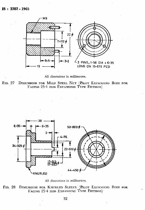
All dimensions in millimetres.
FIG. 27 DIMENSIONS FOR MILD STEEL NUT (PILOT EXPANDING BUSH FOR FACING 25-4 mm EXPANDING TYPE FITTINGS)
z KNURLED 44*450 f-J
All dimensions in millimetres.
FIG. 28 DIMENSIONS FOR KNURLED SLEEVE (PILOT EXPANDING BUSH FOR FACING 25.4 mm EXPANDING TYPE FITTINGS)
32

IS : 3302 - 1965 /
All dimensions in millimetres. .
FIG. 29 DIMENSIONS FOR KNURLED KEY (PILOT EXPANDING BUSH FOR FACING 25.4 mm EXPANDING TYPE FITTINGS)
l-224 L 9.52 DIA x 95.25 LONG SILVER STEEL PIN SHRUNK OR PRESS
FIT IN TAPERED MANDREL.
CENTRE LINE OF PIN PARALLEL TO MANDREL AXIS
All dimensions in millimetres. 8
FIG. 30 DIMENSIONS FOR TAPERED MANDREL (PILOT EXPANDING BUSH FOR I
FACING 38.1, 50.8, 63.5 & 76.2 mm EXPANDING TYPE FITTINGS) I
33 !
/

IS : 3382 - 1965 ’
l--63.500-1
HOLES, 6.35 DIA x 6.35 DEEP
ON 25.400 PC0 L 1.5 t? 28.575 f J
CROOVE
NOTE -Use maximum 3.2 thick saw for cutting into three equal pieces.
OUTER A B DIAMETER
1 OF PIPES Max ~ Min ~ ---
38.1 35.560 35.509 i 32.518
50.8 I 48.000 ~ 47.949 44.450
63.5 59.949 1 59.898 57.150 ~
76.2 72.644 1 72.593 69.850
All dimensions in millimetres.
FIG, 31 DIMENSIONS FOR MOLD STEEL SPLIT BUSH (PILOT EXPANDING BUSH FOR FACING 38.1, 50.8, 63-5 AND 76.2 mm EXPANDING TYPE FITTINGS)
34

IS : 3382 - 1965 1
All dimensions in millimetres.
FIG. 32 DIMENSIONS FOR MILD STEEL NUT (PILOT EXPANDING BUSH FOR FACING 38.1, 50.8, 63.5 AND 76.2 mm EXPANDING TYPE FITTINGS)
/-KNURLED
All dimensions in millimetres.
FIG. 33 DIMENSIONS FOR KNURLED SLEEVE (PILOT EXPANDING BUSH FOR FACING 38.1, 50.8, 63.5 AND 76.2 mm EXPANDING TYPE FITTINGS) I ,
1 35

3382 - 1965
8 DIA x ?T, LONG PIN
12 DIA
tOLE
L 3 D!A i 33 LOI:G PINS’
All dimensions in millimetres.
FIG. 34 DIMENSIONS FOR MILD STEEL HANDLE (PILOT EXPANDING BUSH FOR FACING 38.1, 50.8, 63-5 AND 76.2 mm EXPANDING TYPE FITTINGS)
t i
NOTE:-- To be hardened.
J
All dimensions in millimetres .
FIG. 35 DIMENSIONS FOR” SPHERICAL’ HEXAGONAL HEAD ADAPTOR c
. 36 -..