Embed Size (px)
Citation preview

Indian Standard
RECOMMENDATION FOR ESTIMATION OF FLOW OF LIQUIDS IN
CLOSED CONDUITS PART II .HEAD LOSS IN VALVES AND FITTINGS
Fluid Flow Measurement Sectional Committee, BDC 17
chaimIan DE A. N. KS-LA In pcrammlaphty~(‘Coarrm~ O&q BIvknrmr)
Yh4&ifm.-i
Soar N. D. GULEATI Inpamnalcapuity(f4OSnhNag~,N~lhfhi)
Mb?nbrrs
DB B. K. Aorawu.~ National F’h~cal Laboratory ( CSIR ), New Delhi Soar R. S. A~BAWALA The !5cicnti6e Instrument Co Ltd, Ailahabad
S-1 S. R. C%A~-~EBJEE ( AI&mar ) ,
Siisr P. R. AX~UJA Ministry of Irrigation & Power SHBI V. N. NACUBAJA ( Ahmfe)
Smu BALESHWAB NATE Committee on Plan Project, Planning Commission SEBI K. L. BEATIA Central Bpard of Irrigation & Power C~_XNBEB, IBBI~ATION Public Works Department, Mysore
Sanr D. DODDX’AH ( Ahmate ) S-I R. D. DHIB Central Water k Power Commission
Sa8r R. C. SE=NOY ( Affmat8) mRxcTOa Aodhra Pradesfi Enginccriog Racarch Laboratories
Hydwam DIBEoToZt River Rcsurcb Institute, Wat Ikngal, Calcutta
DEPUTY D~ECTO~ ( Affcmatr ) DI~RCTOB ( Bmwr~ & FLOODS ), Raiiway htardj Ministry of Railways)
RDSO SREX K. K. FBAYJI In pcmaal capacity ( II G@khana Club, N.w Ddhi : SHRr c. v. GOLE Central Water & Power Rcscarcb Station, Poooa
SHBI S. V. CHITALE (A&ma&) PBor N. S. GOVXNDA RAO SABI S. N. GUPTA HYDRAULIC ENMNEEE
SEBI V. D. D-AI Al&mate) SHRI D. V. JOOL~SAB Srmr KANWAB SAIN SHRI K. N. KATEPALIA
Indian Institute of Science, Bangriorc Irrigation Department, UP Bombay Municipal Corporation
Central Board of Irrigation & Power In personal capacity ( c/o ECAFE, Bangkok ) In personal capacity (B-32, Kailarh Cd047
NEW Delhi)
( Gminutd on #ag# i
INDIAN STANDARDS INSTITUTION - -VAN, 9 BAHADU’R SiW3 ZATM lMII0
NEW DBLHI 110002
(Cdfm,psg8 1)
M8mbm MBMSBB ( DIIX~N & R~luaca ) SRBI M. P. NA~ABS~XTE Sarx A. N. Smn BP~BWT~NDINO BaoIX'JBxB
( D~ltoarr ) ExscuTIPI ENOINBBB
( Rae~rca ) ( Al&mute) DB H. L. Urrrr
Da H. C. VXWXWABAYA, Deputy Director (civil Eng)
R8pW#ttillg Central Water k Power Commission Roads Wing, Ministry of Transport National Instrument ( Private) Ltd, colcutu Public Works Department, Madras
Land Rcclamatio?, Irrigation & Power Racucb Institute, Punjab; and Institution of Engineen ( India ), Calcutta
Director, IS1 ( J&-o&b Mnnber )
S#CrC@ SEBI K. RAOHAVXNDBAN
Extra Assistant Director ( Civil Eng ), IS1
Fluid Flow Measurement in Closed Conduits Subcommittee, BDC 17:3
anrmn PBO? N. S. GOVINDA RAO ~IluWteofW~-8--
iilmbers Sara K. SXET~AEAHIAH ( Allmcrtr to
Prof N. S. Govioda Rao ) AD;F;;;x, Caru Enolloln P.W.D. Health, Rajaathan
Saax P. S. RA.WANSHI ( Aflcrndc ) Dn B. K. AOABWALA National Physical Laboratory ( CSIR ), New Delhi Snlrr BALWANT SINOH Municipal Corporation of Delhi Sarr K. K. FUAMJI In personal capacity ( 11 Gpkhona Club, New Delhi) HYDBIULIC ENOINX~ Bombay Municipal Corporation
Snsr V. D. DEXIAC ( Al&mate) Da INDEE JIT SINOH Oil & Natural Gas Commission
%arH.P. ABAEANACA~&II&) Corooration of Caloutta . Paax S. K. KABASI
BEEI A. N. KBISEN.:SWAMY SBBI I. N. MEETA
SH~I D. R. SINGAL ( Ahem&) SERI R. S. MSETA
W.Ik Brady & Co Ltd, Bombay P.W.D. Public Health Branch, Punjab
Central Public Health Engineering Raearch Institute ( CSIR ), Nagpur
SHRI J. S. JAIN ( Altrrnnfc) Poor S. NAGAEATNAM Sasr M. PANIKEAB SEIU S. RAJAOO~ALAN
SHRI T. DURAIELAJ (Ahnate) Da V. RAMAKRIWNAN
Regional Engineering College, Warangal Mahindra Engineering Co Ltd, Calcutta I%rcrtoratc General of Health Services, Ministry of
Health
?.S.G, College of Technology, Coimbatorc . I Da. S.BALAKRI~ENAN (Altmure)
RBPRESENTATIVE Central Water & Power Research Station, Poona, SUPBRINTENDINO EN o I N E I R Public Works Department, Madras
(DEsIONs) EX~~CUTIVE EN~INE~B (RUURCH) (Afternols)
2

xsr2951(P8rtxI)-1%5~
Indian Standard
RECOMMENDATION FOR ESTIMATION OF FLOW OF LIQUIDS IN
CLOSED CONDUITS PART II HEAD LOSS IN VALVES AND FITTINGS
0. FOREWORD 0.1 This Indian Standard was adopted by the Indian Standards Institu- tion on 24 March 1965, after the draft finalized by the Fluid Flow Measurement Sectional Committee had been approved by the Civil Engineering Division Council. Of Fittings in a pipe line like’Svalves, bends, tees, reducers, couplings, branches offer considerable resistance to flow of liquids. The loss of head caused by a fitting is partly due to the sinuous motion set up by the expansion of the stream to fill the pipe after its contraction in passing the valve and partly to the irregularities in the shape of the water-way through the valve. The head loss due to valves and other fittings is relatively more important particularly in smooth and short pipe lines and a knowledge of these losses is essential for proper designing of pipe line *ystems. 0.3 Losses due to fittings are sometimes expressed in terms of the length of straight pipe of a given diameter which gives an equivalent loss of head. This method is very approximate as the equivalent length is dependent upon pipe friction law and to some extent on diameter. Experiments have been conducted on several occasions on various kinds and sixes of fittings. For example, systematic study for the revision of pipe friction data has been done by the Hydraulic Institution at New York and their publication entitled ‘Pipe friction manual’ gives the result of their investi- gation. In the light of such studies this standard recommends the values of resistance coefficients for different types of fittings. 0.4 The Sectional Committee responsible for the preparation of this standard has taken into consideration the views of users and technologists and has related the standard to the practices followed in the country in this field. Due weightage has also been given to the need for international co-ordination a.mong standards prevailing in different countries of the world. These considerations led the Sectional Committee to derive assistance from the following publications:
ISO Draft Recommendation No. 532 Measurement of fluid flow by means of orifice plates and nozzles.
Pipe friction manual. 1954. Hydraulic Institute, New York.
3
lS:2951(PartIl)-1965 ,
0.5 This standard is one of a se+ of Indian Standards covering fluid flow measurement in closed conduits. Other standards in the series are:
IS : 2951 ( Part I )-1965 Recommendation for estimation of flow of liquids in closed conduits : Part I Head loss in straight pipes due to frictional resistance.
IS : 2952 ( Part I )-I964 Measurement of fluid flow by means of orifice plates and nozzles : Part I Incompressible fluids.
0.6 For the purpose‘of deciding whether a particular requirement of this standard is complied with, the final value, observed or calculated, express- ing the result of a test or analysis, shall be rounded off in accordance with IS : 2-196W. The number of significant places retained in the rounded off value should be the same as that of the specified value in this standard.
1. SCOPE
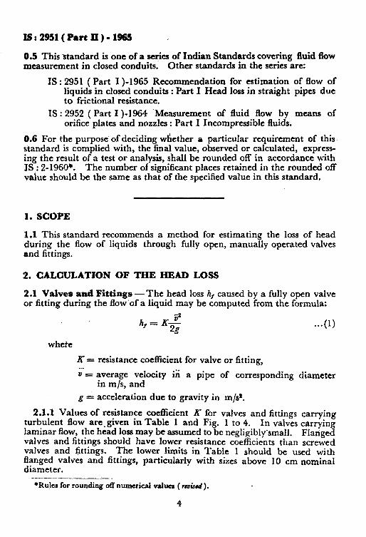
1.1 This standard recommends a method for estimating the loss of head during the flow of liquids through fully open, manually operated valves and fittings.
2. CALCULATION OF THE HEAD LOSS
2.1 Valves and Fittings -The head loss h, caused by a fully open valve or fitting during the flow’of a liquid may be computed from the formula:
where
X= resistance coefficient for valve or fitting, - a = average velocity iii a pipe of corresponding diameter
in m/s, and
g = acceleration due to gravity in m/s”.
23.1 Values of resistance coefficient R for valves and fittings carrying turbulent flow are.given in Table 1 and Fig. 1 to 4. In valves carrying laminar flow, the head loss may be assumed to be negligibly~small. Flanged valves and fittings should have lower resistance coefficients than screwed valves and fittings. The lower limits in Table 1 should be used with flanged valves and fittings, particularly with sizes above 10 cm nominal diameter.
-..______-- *Rules for rounding off numerical values ( rwirrd).
4
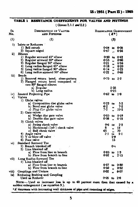
TABIS I ~TANCR COEFFlCIElUTS FOR VUVBS AND FZZTINGS ( Clsws 2.1.1 Qd2.2 )
FE D~KJIUPTION ox Vuvxo
m FII?I~N~S
(1) (2)
i) Inlets or Reducers 1) &ll mouth 2) Square edged
ii) Elbowa 1) Regular screwed 45’ elbow 2) Regular screwed 90° elbow 3) Regular flanged 90’ elbow 4) Long radius tlanged 45O elbow 5) Long radim flanged 90’ elbow 6) Long radius screwed 90° elbow
RuurrAzXJx Gorrrrarurr (K*)
(8)
804 to 685 047 :, 856
030 to 842 g;: 1, m
818 * 830 ,, 820
614 823 022 II 068
iii) B&dr - 1) Screwed return bend, close-pattern 2) Flanxcd return bend corn& of
.-
o-75 to 2.2
two -W tlanged elbows a) Regular b) Long radius
iv) Inward Projecting Pipe v) Valves
1) Globe v&es’
- 0.38 @25
062 to l-8
a) Composition disc globe valve @23 te 52 b) Bevel seat globe valve c) Plug disc globe valve
62 ,, 7.2 7.2 ), 103
2) Gatevalva a) Wedge disc gate valve 005 to O-19 b) Double disc gate valve 0.08 n 613
3) Check valves a) Swing check valve 06 to 2.3 b) Horizontal (left ) check valve 9, 12 c) Ball check valve 6: 70
4) Angle valve 21 & S-1 5) Y or blow off valve 2-9 6) Foot valve 15
vi) Standard Screwed Tee 1) Branch blanked off 84 2) Line blanked off
a) Flow from line to branch 885 to l-3 b) Flow from branch to line 692 ,, 2’15
vii) Long Radius Screwed Tee I) Line blanked off
a) Plow from line to branch b) Flow from branch to line o&z to 980 852
viii) Couplings and Unions 082 :: 807 ix) Reducing Bushing and Coupling
Used as Reducer 085 co 28 Noxx- Used as increaser loss is up to 48 percent more than that mued by a
sudden' enlargement ( m equation 3 ) . +d decrease with increasing wall thiclrnar of pipe and roun&8 dodgea.
5

18:295l(PartII)-1965
2.2 PiPe-Bends and Elbows - Values of the absolute roughness K, shall be obtained from Fig, 1 or Table 1 of IS : 295 1 ( Part I ) .. 1965t, and knowing the relative roughness K./D, the values of K for 90” bends may be taken from Fig. 1 for the given ratio of r] D, where t is radius of the bend and D the diameter of the pipe.
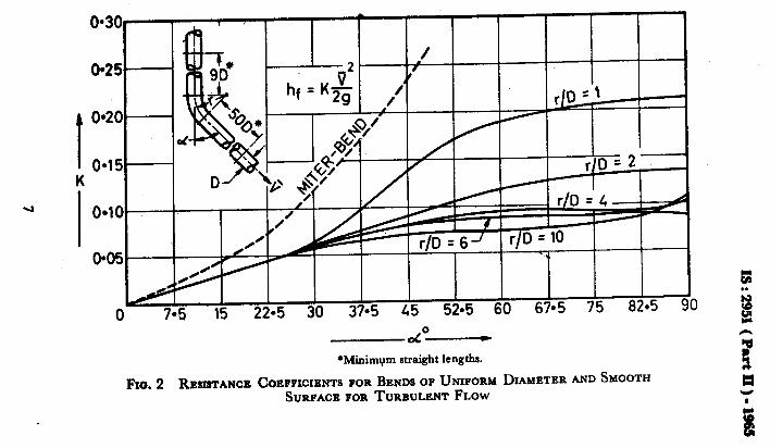
2.2.1. The resistance coefficient X for smooth bends with deflection angles less than 90” shall be obtained from Fig. 2
2.2.2 Where the pipes are not smooth, these coefficients may have to be increased from 30 to 50 percent or depending upon their roughness. The value of K given in Table 1 and in Fig. 1 and 2 applies only if the pipe has linear lengths upstream and downstream not less than those shown in the respective figures.
2.2.3 For r/D values less than unity, use of Fig. 1 and 2 is not recom- mended. .
hi -2
f=K&
I 04
K o-3
I ‘\ 0.2 4020 l 0015 a0010 -0005
dcunntu I \_ 0 - 04 -_ _ 17 1 t-t -- r -
1 I r I-I”” I I ‘1
I I
I I I I I O% 1 2 3 L
I I’ I I I J 5 6 7 8 9 10
--- ;,
*Minimum straight length.
FIG. I RESISTANCE COEFFICIENTS FOR 90’ BENDS OF UNIFORM DIAMETER
tRcuxnmcndPtion for utinution of Ilow of liquida in clnecd conduits : Part I Had ’ b ie straight pipea due to frictional rcsist~ce.
6
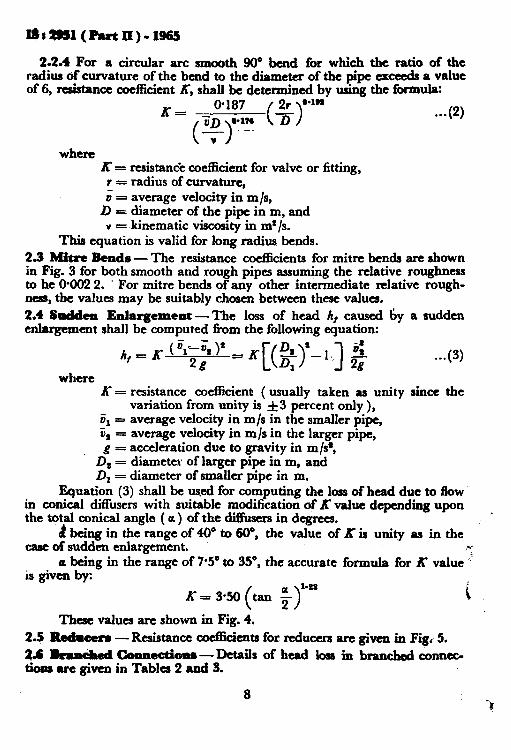
2.24 For a circular arc smooth 90” bend for which the ratio of the radius of curvature of the bend to the diameter of the pipe exceeds a value of 6, resistance coefficient K, shall be determined by using the farmula:
A-= 0187 2r 0*1n
jjD 0.1% . ..(2)
( )
( > 7 - --
V
where K = resistan& coefficient for valve or fitting, I = radius of curvature, 0 = average velocity in m/s,
D = diameter of the pipe in m, and v = kinematic viscosity in m2/s.
This equation is valid for long radius bends.
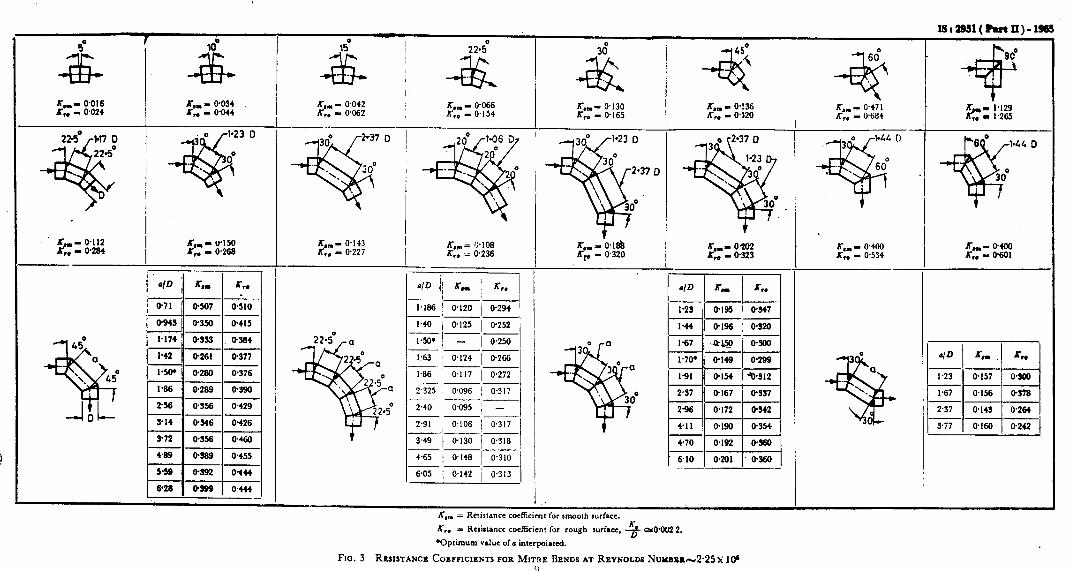
2.3 Mitre Bends - The resistance coeflicients for mitre bends are shown in Fig. 3 for both smooth and rough pipes assuming the relative roughness to be @002 2. ’ For mitre bends of any other intermediate relative rough- ness, the values may be suitably chosen between these values.
2.4 Sudden Enlargement -The loss of head A, caused by a sudden enlargement shall be computed from the following equation:
h,=K( + ;DI )’
2g -K[@>‘-l] 5 ..a
where K = resistance coefficient ( usually taken as unity since the
variation from unity is &3 percent only ), v, = average velocity in m/s in the smaller pipe, 5, = average velocity in m/s in the larger pipe,
g = acceleration due to gravity in m/s’, D2 = diameter of larger pipe in m, and D z = diameter of smaller pipe in m.
Equation (3) shall be wed for computing the loss of head due to flow in conical diffusers with suitable modification of K value depending upon the total conical angle ( a ) of the diffusers in degrees.
~
d being in the range of 40” to fW, the value of K is unity as in the case of sudden enlargement. .W
a being in the range of 7.5” to 35’, the accurate formula for K value * is givtn bv:
K- 3.50 (tan ;r2*
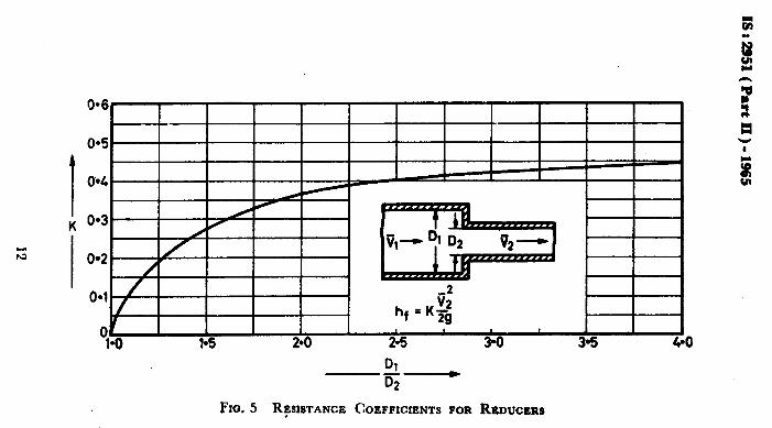
These values arc shown in Fig. 4. 2.5 Redmcera -Resistance co&cients for reducers are given in Figi 5.
a.6 lrrncbmd Connectiona-Details of head loss in branched connec- tions are given in Tables 2 and 3.
i
8

As in the Original Standard, this Page is Intentionally Left Blank

0*9
O-9
O-7
04
04
0.4
t2-- ~B!S!W(______
i-02-i Q ‘IN PEGREES
L 4 L‘
FIG. 4 RESISTANCE COEPFICI~SY pop INCREASERS AND DIFFUSERS
RUSSELL I = 150 mm ---
I = 300 mm ----
L z 4SOmm -a-
tan: = (D2- D,)/21
a I
f

TAnLE2 muDLOSSINBRANctiKDcONNEcTI ONS (DIVIDED FLOW)
(Ccour 2.6)
-vwg
i? He@ loss at branching (h,) = C 2g
X is r&stance coefficient, and
9,& D and 9a, &, Db are discharge, average velocity and diameter of original and branch pipes respectively.
AlvaLE OF
DIVEB- 9bhrm3 9J9=03 9b/9"0'7
r--- seNcEpm
DEGBIWI &% ‘x Rounded ----Rounded.
f=0*1& Edged Sharp
r=&l D, w+ r=O-1D3
(1) (2) (3) (4) (5) (6) (7)
I D,--D &,=D &,=D Db=D Db=D D,=D
90
i
,-,=@3; i&=0-3; ;,, = 0-5; ;b - 0.5; ;b = 0-7; ;b = 0-7;
K -- 0.85 K-O-76 X-O-87 K-O-74 K = l*GO K-o.80
’ -” = D
Db=o’61D Db=D Db=@790 DbnD Da = D
60
I
;b = 0-3; ;b*O.& ;b = 0.5 ;b = 0.6 ;b = @7; ;a=@%
K=@7 K-O-59 K-O-59 X50-54 K = 067 K-O-52
i
Db=@58D Db=O+6D Db=D D,=@75D D,=D Db=D
45 ;;b = 0.c ;b = 0% ;b = 0-5; ;b = 0.9; ;b = 0.7;; ;,, = 0-7
X=0-43 K=Q35 X=0-42 t=@32 K=@34 K-O-3
NOTIJ -These values are based#on the experiments conducted at the Hydraulic Laboratory of the Technical University of Munich, G crmany, for most efficient case.
13
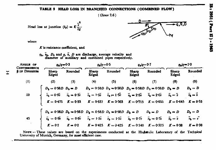
. TABLE 3 HEAD LOSS IN SRANCHitD CONNECT! ON8 (COMBINED FLOW)
( Cfuusc 2.6)
-_ a Head loss at junction (/I/) = “G
where
K is reairtance coefficient, and
qbs i,, Db and q, 6 D 8rc disc-huge, average v&city and diameter of auxiliary and combined pipa rupectively.
ANiJLll or CoNvrRasrK!E
dP=@~ qb/q=@5 qbk=O’7 4blP 1.0
z B xx Dsomt~e ----YGz Shnrp ----iGz
$2 ----xzz.-
WFd k=& Sh=P Rounded
Edged
(1) (2) (3) (4) (5) (6) (7) (8) (9)
r D,=O%D D,= D Db = @58D D, =@5BD Db =.@58D D, = @58D D, = D Db = D
60
i
:b = 0.9; h = 03’0 Jb = 1.5; ;b P 1.5; & P 2.0; ;;a E’POil ;b = ; -,I=;
1 K= 0.475 KPO-QS X=+637 K=OS3 K-0915 K-O.655 K-O.645 K-O.53
f Db= 0.580 Db -0f18D D,=@58D Db=ofi8D 4-D D,=D Db=D Db=D
45 i
6 -_ 0.5 ;, = O-9; ;b = 1.5; ;b = 1.5;; 4 = 0.7; ;;, = 0.7; ;b = ; ';a = 0'
I K=@2 K-O.2 X=0*425 Kail.425 X=0.540 K=0.525 X=098 K-=&38
NOTE -These values are based on the experimenti conducted at the I-J,&ulic Laboratory of the Technical University of Munich, Germany, for most efikient case.

AMENDMENT NO. 1 MARCH 1993 TO
IS 2951( Part 2 ) : 1965 RECOMMENDATION FOR ESTIMATION OF FLOW OF LIQUIDS IN CLOSED
CONDUITS
PART2 HEAD LOSS IN VALVES AND FllTlNGS
[ Fage 5, Table 1, SZNo. (v) (6), coZ3 ] -Substitute ‘0.8' for ‘15’.
Reprography Unit, BIS, New Delhi, India

![Payment of Bonus Act, 1965 - Labour Department - Bihlabour.bih.nic.in/Acts/payment_of_bonus_act_1965.pdf · THE PAYMENT OF BONUS ACT, 1965 ACT NO. 21 OF 1965 [25th September, 1965.]](https://img.pdfslide.us/doc/110x75/5a8ea43b7f8b9a78648d3a37/payment-of-bonus-act-1965-labour-department-payment-of-bonus-act-1965-act.jpg)