Embed Size (px)
Citation preview
Disclosure to Promote the Right To Information
Whereas the Parliament of India has set out to provide a practical regime of right to information for citizens to secure access to information under the control of public authorities, in order to promote transparency and accountability in the working of every public authority, and whereas the attached publication of the Bureau of Indian Standards is of particular interest to the public, particularly disadvantaged communities and those engaged in the pursuit of education and knowledge, the attached public safety standard is made available to promote the timely dissemination of this information in an accurate manner to the public.
इंटरनेट मानक
“!ान $ एक न' भारत का +नम-ण”Satyanarayan Gangaram Pitroda
“Invent a New India Using Knowledge”
“प0रा1 को छोड न' 5 तरफ”Jawaharlal Nehru
“Step Out From the Old to the New”
“जान1 का अ+धकार, जी1 का अ+धकार”Mazdoor Kisan Shakti Sangathan
“The Right to Information, The Right to Live”
“!ान एक ऐसा खजाना > जो कभी च0राया नहB जा सकता है”Bhartṛhari—Nītiśatakam
“Knowledge is such a treasure which cannot be stolen”
“Invent a New India Using Knowledge”
है”ह”ह
IS 2532 (1965): Hard-drawn copper wire for telegraph andtelephone purposes [ETD 37: Conductors and Accessories forOverhead Lines]

IS : 2532 - 1965
Indian Standard SPECIFICATION FOR
HARD-DRAWN COPPER WIRE FOR TELEGRAPH AND TELEPHONE PURPOSES
Second Reprint JULY 1983 ( Incorporating Amendments No. 1 and 2 )
UDC 621.315.55 : 669.3-426
© Copyright 1975
I N D I A N S T A N D A R D S I N S T I T U T I O N MANAK BHAVAN, 9 BAHADUR SHAH ZAFAR MARG
NEW DELHI 110002
Gr 3 August 1965
IS : 2532 - 1965
Indian Standard SPECIFICATION FOR
HARD-DRAWN COPPER WIRE FOR TELEGRAPH AND TELEPHONE PURPOSES
Conductors and Cables Sectional Committee, ETDC 32
Chairman Representing SHRI V. VENUGOPALAN Central Water & Power Commission (Power
Wing) Members
SHRI L. C. BANSAL Electrical Manufacturing Co Ltd, Calcutta SHRI R K. SENGUPTA ( Alternate )
SHRI P. K. BHARUCHA Insurance Association of India, Bombay SHRI A. C. MODY ( Alternate )
SHRI M. R. BHAT Bombay Suburban Electric Supply Ltd, Bombay SHRI R. BOWYER Indian Cable Co Ltd, Calcutta SHRI N. P. GHOSH Inspectorate of Mines ( Ministry of Labour &
Employment ) SHRI H. K. BHATTACHARJEE ( Alternate )
SHRI D. T. GURSAHANI Directorate General of Supplies & Disposals ( Inspection Wing )
SHRI P. L. KAPUR ( Alternate ) SHRI S. K. KANJILAL Railway Board ( Ministry of Railways )
SHRI N. PADMANABHAN ( Alternate ) SHRI H. S. KULKARNI Federation of Electricity Undertakings of India
Ltd, Bombay SHRI D. M. LAM Directorate General of Posts & Telegraphs
( Ministry of Transport & Communications ) SHRI T. K. SUBRAMANIAN ( Alternate )
SHRI M. R. LODH Devidayal Cable Industries Ltd, Bombay SHRI KAMAL AGGARWAL ( Alternate )
WG CDR D. J. LAWYER Directorate of Technical Development & Production ( Air ) ( Ministry of Defence )
SQN LDR S. B. PURANIK ( Alternate ) SHRI J. LYON Fort Gloster Industries Ltd, Calcutta
SHRI G. P. SAXENA ( Alternate ) SHRI A. J MEHTA Gujarat Electricity Board, Baroda
SHRI J. H. PATEL ( Alternate ) COL M. L. MIDHA Controller General of Inspection & Planning
( Ministry of Defence ) SHRI S. K. MANI ( Alternate )
( Continued on page 2 )
I N D I A N S T A N D A R D S I N S T I T U T I O N MANAK BHAVAN, 9 BAHADUR SHAH ZAFAR MARG
NEW DELHI 110002
IS : 2532 - 1965
( Continued from page 1 )
Members Representing SHRI P. S. SRINIVASA MODALIAR Radio & Electricals Manufacturing Co Ltd,
Bangalore SHRI V. R. CHANDER ( Alternate )
SHRI S. N. M U K E R J I National Test House, Calcutta SHRI B. K. M U K H E R J E E ( Alternate )
SHRI V. G. G. NAYAR Aluminium Industries Ltd, Kundara SHRI S. P E E R MOHAMMED ( Alternate )
SHRI S. R. C. POTI Asian Cables Corporation Ltd , Bombay SHRI A. K. RAMAN ( Alternate )
SHRI A. M. RAMALINGAM Madras State Electricity Board, Madras SHRI K A. SUBBAMANIAM ( Alternate )
SHRI K. N. RAMASWAMY Directorate General of Technical Development ( Heavy Electricals Directorate ) ( Ministry of Industry )
SHRI M. J. R A O Tata Hydro-Electric Supply Co Ltd, Bombay SHRI M. V. GONDHALEKAR ( Alternate )
SHRI T. S. R A O In personal capacity ( 'Bhavani', No. 23, Block III, Jayanagar, Bangalore )
REPRESENTATIVE Electrical Inspector to the Government of West Bengal, Calcutta
SHRI S. K. R O Y Hindustan Cables Ltd, Rupnarainpur SHRI K P. PILLAY ( Alternate )
SHRI D. P. SAHAI National Insulated Cable Co of India Ltd, Calcutta
SHRI B. H. R A I ( Alternate ) SHRI S. M. SAHAI Alcan Asia Ltd, Calcutta SHRI L. R. SUBRAMANYAM Henley Cables ( India ) Ltd, Bombay
SHRI K. V. RAMA R A O ( Alternate ) SUPERINTENDING SURVEYOR OF Central Public Works Department
W O R K S ( ELECTRICAL ) SHRI G. H. SWATEK Cable Corporation of India Ltd, Bombay
DR P. S. SHAH ( Alternate ) CAPT B. Y. W A D Naval Headquarters
CDR P. S. M E H T A ( Alternate ) SHRI Y. S. VENKATESWARAN, Director, ISI ( Ex-officio Member )
Deputy Director ( Electro-technical ) ( Secretary )
2
IS : 2532 - 1965
Indian Standard SPECIFICATION FOR
HARD-DRAWN COPPER WIRE FOR TELEGRAPH AND TELEPHONE PURPOSES
0 . F O R E W O R D
0.1 This Indian Standard was adopted by the Indian Standards Institution on 28 April 1965, after the draft finalized by the Conductors and Cables Sectional Committee had been approved by the Electrotechnical Division Council.
0.2 This standard has been formulated at the instance of Indian Posts and Telegraphs Department to cover suitable hard-drawn copper wire having the requisite electrical and physical properties for telegraph and telephone purposes.
0.3 These hard-drawn copper wires are covered by Telegraph Wires (Unlawful Possession) Act, No. LXXIV of 1950 with all amendments.
0.4 In preparing this standard, assistance has been derived from B. S. 174 : 1951 'Hard-drawn copper wire for telegraph and telephone purposes' and B. S. 125 : 1954 'Hard-drawn copper conductors for overhead power transmission purposes' issued by the British Standards Institution.
0.5 For the purpose of deciding whether a particular requirement of this standard is complied with, the final value, observed or calculated, expressing the result of a test, shall be rounded off in accordance with IS : 2-1960*. The number of significant places retained in the rounded off value should be the same as that of the specified value in this standard.
1. SCOPE
1.1 This specification covers the requirements for hard-drawn solid circular copper conductors for telegraph and telephone purposes.
*Rules for rounding off numerical values ( revised ).
3
IS : 2532 - 1965
*Glossary of terms for electrical cables and conductors. †Specification for hard-drawn copper conductors for overhead power transmission
( revised ).
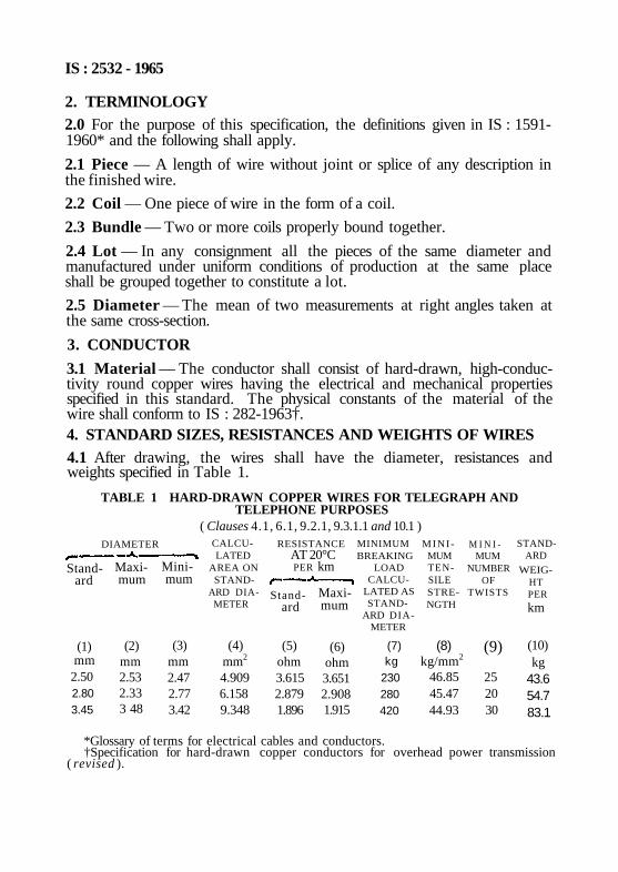
2. TERMINOLOGY 2.0 For the purpose of this specification, the definitions given in IS : 1591-1960* and the following shall apply.
2.1 Piece — A length of wire without joint or splice of any description in the finished wire.
2.2 Coil — One piece of wire in the form of a coil.
2.3 Bundle — Two or more coils properly bound together.
2.4 Lot — In any consignment all the pieces of the same diameter and manufactured under uniform conditions of production at the same place shall be grouped together to constitute a lot.
2.5 Diameter — The mean of two measurements at right angles taken at the same cross-section.
3. CONDUCTOR
3.1 Material — The conductor shall consist of hard-drawn, high-conductivity round copper wires having the electrical and mechanical properties specified in this standard. The physical constants of the material of the wire shall conform to IS : 282-1963†. 4. STANDARD SIZES, RESISTANCES AND WEIGHTS OF WIRES 4.1 After drawing, the wires shall have the diameter, resistances and weights specified in Table 1.
TABLE 1 HARD-DRAWN COPPER WIRES FOR TELEGRAPH AND TELEPHONE PURPOSES
( Clauses 4.1, 6.1, 9.2.1, 9.3.1.1 and 10.1 ) RESISTANCE
AT 20°C PER km Stand
ard
(1) mm
2.50 2.80 3.45
Maximum
(2) mm 2.53 2.33 3 48
Minimum
(3) mm 2.47 2.77 3.42
CALCULATED
AREA ON STAND
ARD DIA-METER
(4) mm2
4.909 6.158 9.348
MINIMUM TEN-SILE STRENGTH
(8) kg/mm2
46.85 45.47 44.93
DIAMETER
Stand-ard
(5) ohm 3.615 2.879 1.896
Maximum
(6) ohm 3.651 2.908 1.915
MINIMUM BREAKING
LOAD CALCU
LATED AS STAND
ARD DIAMETER
(7) kg
230 280 420
M I N I -MUM
NUMBER OF
TWISTS
(9)
25 20 30
STAND-ARD
WEIG-HT PER
km
(10) kg
43.6 54.7 83.1
IS : 2532 - 1965
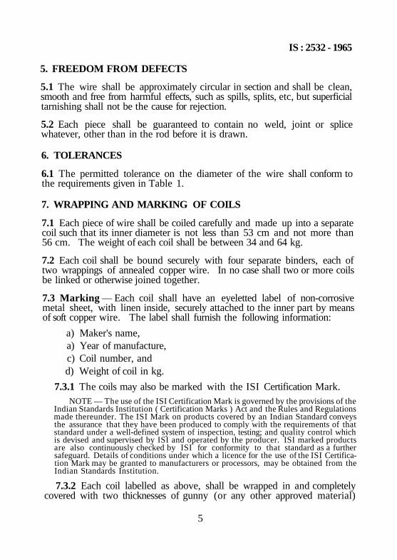
5. FREEDOM FROM DEFECTS
5.1 The wire shall be approximately circular in section and shall be clean, smooth and free from harmful effects, such as spills, splits, etc, but superficial tarnishing shall not be the cause for rejection.
5.2 Each piece shall be guaranteed to contain no weld, joint or splice whatever, other than in the rod before it is drawn.
6. TOLERANCES
6.1 The permitted tolerance on the diameter of the wire shall conform to the requirements given in Table 1.
7. WRAPPING AND MARKING OF COILS
7.1 Each piece of wire shall be coiled carefully and made up into a separate coil such that its inner diameter is not less than 53 cm and not more than 56 cm. The weight of each coil shall be between 34 and 64 kg.
7.2 Each coil shall be bound securely with four separate binders, each of two wrappings of annealed copper wire. In no case shall two or more coils be linked or otherwise joined together.
7.3 Marking — Each coil shall have an eyeletted label of non-corrosive metal sheet, with linen inside, securely attached to the inner part by means of soft copper wire. The label shall furnish the following information:
a) Maker's name, a) Year of manufacture, c) Coil number, and d) Weight of coil in kg.
7.3.1 The coils may also be marked with the ISI Certification Mark. NOTE — The use of the ISI Certification Mark is governed by the provisions of the
Indian Standards Institution ( Certification Marks ) Act and the Rules and Regulations made thereunder. The ISI Mark on products covered by an Indian Standard conveys the assurance that they have been produced to comply with the requirements of that standard under a well-defined system of inspection, testing; and quality control which is devised and supervised by ISI and operated by the producer. ISI marked products are also continuously checked by ISI for conformity to that standard as a further safeguard. Details of conditions under which a licence for the use of the ISI Certification Mark may be granted to manufacturers or processors, may be obtained from the Indian Standards Institution.
7.3.2 Each coil labelled as above, shall be wrapped in and completely covered with two thicknesses of gunny (or any other approved material)
5
IS : 2532 - 1965
outside of which a duplicate label shall be attached before being packed for despatch.
8. SAMPLING AND CRITERIA FOR CONFORMITY
8.1 The number of pieces to be examined from each lot for freedom from defects (see 5) and for tolerance on sizes (see 6) and the corresponding criteria for conformity shall be as agreed to between the supplier and the purchaser.
8.2 From each lot, the number of coils as specified in Table 2 shall be selected at random. From each of the coils so selected, one test piece of the required or specified length for Wrapping test (see 9.1), tensile test (see 9.2) torsion test (see 9.3) and resistance test (see 10), shall be cut from the ends and subjected to those tests. The test pieces may also be cut from any part of the coil other than ends in one of the selected coils; the cut lengths of the coil shall not be welded or otherwise jointed together. Each cut length shall be wound up into a separate coil and accepted or rejected as mutually agreed upon at the time of placing the order.
The length of sample selected for the electrical resistance test shall be sufficient to give the accuracy required and shall be suitable for the method of testing employed.
8.3 The lot shall be considered as conforming to the requirements of the tensile strength and electrical resistance as laid down in this standard if the mean and the range calculated from the test results for each characteristic satisfy the conditions given below:
a) ( Mean + 0.6 Range ) shall be less than or equal to the corresponding maximum specified limit.
b) ( Mean — 0.6 Range ) shall be greater than or equal to the corresponding minimum specified limit.
NOTE 1 — Range it the difference between the maximum and the minimum values of the test results.
NOTE 2 — This ensures that lots containing 0.5 percent or less defective coils will be accepted most of the time.
8.4 The lot shall be considered as conforming to the requirements of the wrapping test and torsion test if the number of failures is less than or equal to the permissible number given in col 3 of Table 2.
9. MECHANICAL TESTS
9.1 Wrapping Test
9.1.1 The wire shall not break when tested by wrapping round a wire of its own diameter to form a close helix of eight turns and unwrapping
6
IS : 2532 - 1965
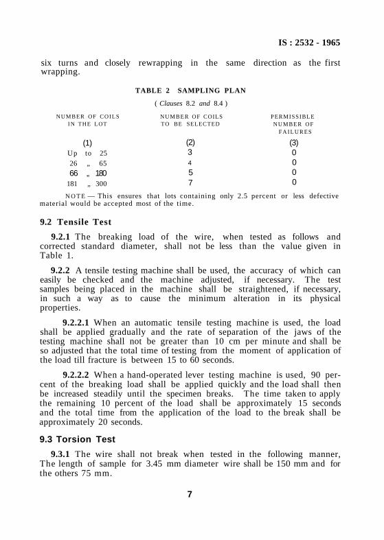
six turns and closely rewrapping in the same direction as the first wrapping.
9.2 Tensile Test
9.2.1 The breaking load of the wire, when tested as follows and corrected standard diameter, shall not be less than the value given in Table 1.
9.2.2 A tensile testing machine shall be used, the accuracy of which can easily be checked and the machine adjusted, if necessary. The test samples being placed in the machine shall be straightened, if necessary, in such a way as to cause the minimum alteration in its physical properties.
9.2.2.1 When an automatic tensile testing machine is used, the load shall be applied gradually and the rate of separation of the jaws of the testing machine shall not be greater than 10 cm per minute and shall be so adjusted that the total time of testing from the moment of application of the load till fracture is between 15 to 60 seconds.
9.2.2.2 When a hand-operated lever testing machine is used, 90 percent of the breaking load shall be applied quickly and the load shall then be increased steadily until the specimen breaks. The time taken to apply the remaining 10 percent of the load shall be approximately 15 seconds and the total time from the application of the load to the break shall be approximately 20 seconds.
9.3 Torsion Test
9.3.1 The wire shall not break when tested in the following manner, The length of sample for 3.45 mm diameter wire shall be 150 mm and for the others 75 mm.
7
TABLE 2 SAMPLING PLAN
( Clauses 8.2 and 8.4 )
NUMBER OF COILS I N THE LOT
(1) Up to 25
26 „ 65
66 „ 180 181 „ 300
NUMBER OF COILS TO BE SELECTED
(2) 3 4
5 7
PERMISSIBLE NUMBER OF
F A I L U R E S
(3) 0 0 0 0
N O T E — This ensures that lots containing only 2.5 percent or less defective material would be accepted most of the time.
IS : 2532 - 1965
9.3.1.1 The sample shall be gripped in two vices one of which should be free to move in the direction of the axis of the wire whilst the other shall be arranged to rotate upon the axis of the wire. The latter vice shall be made to rotate at a speed not exceeding one revolution per second for the minimum number of twists given in Table 1.
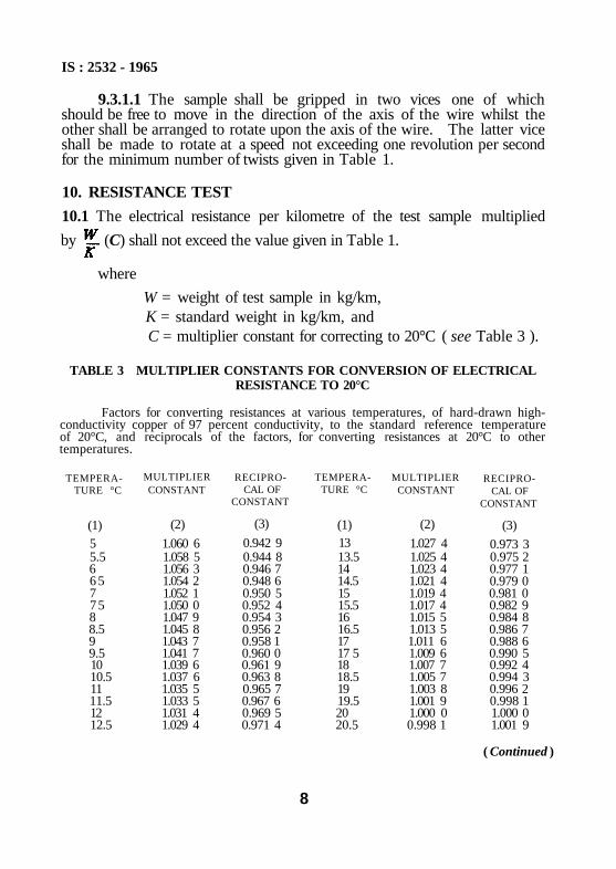
10. RESISTANCE TEST
10.1 The electrical resistance per kilometre of the test sample multiplied
by (C) shall not exceed the value given in Table 1.
where
W = weight of test sample in kg/km, K = standard weight in kg/km, and C = multiplier constant for correcting to 20°C ( see Table 3 ).
TABLE 3 MULTIPLIER CONSTANTS FOR CONVERSION OF ELECTRICAL RESISTANCE TO 20°C
Factors for converting resistances at various temperatures, of hard-drawn high-conductivity copper of 97 percent conductivity, to the standard reference temperature of 20°C, and reciprocals of the factors, for converting resistances at 20°C to other temperatures.
TEMPERA-TURE °C
(1) 5 5.5 6 6 5 7 7 5 8 8.5 9 9.5 10 10.5 11 11.5 12 12.5
MULTIPLIER CONSTANT
(2)
1.060 6 1.058 5 1.056 3 1.054 2 1.052 1 1.050 0 1.047 9 1.045 8 1.043 7 1.041 7 1.039 6 1.037 6 1.035 5 1.033 5 1.031 4 1.029 4
RECIPROCAL OF
CONSTANT
(3)
0.942 9 0.944 8 0.946 7 0.948 6 0.950 5 0.952 4 0.954 3 0.956 2 0.958 1 0.960 0 0.961 9 0.963 8 0.965 7 0.967 6 0.969 5 0.971 4
TEMPERATURE °C
(1) 13 13.5 14 14.5 15 15.5 16 16.5 17 17 5 18 18.5 19 19.5 20 20.5
MULTIPLIER CONSTANT
(2)
1.027 4 1.025 4 1.023 4 1.021 4 1.019 4 1.017 4 1.015 5 1.013 5 1.011 6 1.009 6 1.007 7 1.005 7 1.003 8 1.001 9 1.000 0 0.998 1
RECIPROCAL OF
CONSTANT
(3)
0.973 3 0.975 2 0.977 1 0.979 0 0.981 0 0.982 9 0.984 8 0.986 7 0.988 6 0.990 5 0.992 4 0.994 3 0.996 2 0.998 1 1.000 0 1.001 9
8
( Continued )
lS : 2532 - 1965
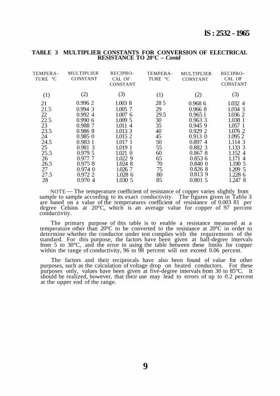
TABLE 3 MULTIPLIER CONSTANTS FOR CONVERSION OF ELECTRICAL RESISTANCE TO 20°C – Contd
TEMPERA-TURE °C
(1)
21 21.5 22 22.5 23 23.5 24 24.5 25 25.5 26 26.5 27 27.5 28
MULTIPLIER CONSTANT
(2)
0.996 2 0.994 3 0.992 4 0.990 6 0.988 7 0.986 8 0.985 0 0.983 1 0.981 3 0.979 5 0.977 7 0.975 8 0.974 0 0.972 2 0.970 4
RECIPROCAL OF
CONSTANT
(3)
1.003 8 1.005 7 1.007 6 1.009 5 1.011 4 1.013 3 1.015 2 1.017 1 1.019 1 1.021 0 1.022 9 1.024 8 1.026 7 1.028 6 1.030 5
TEMPERATURE °C
(1) 28 5 29 29.5 30 35 40 45 50 55 60 65 70 75 80 85
MULTIPLIER CONSTANT
(2)
0.968 6 0.966 8 0.965 1 0.963 3 0.945 9 0.929 2 0.913 0 0.897 4 0.882 3 0.867 8 0.853 6 0.840 0 0.826 8 0.813 9 0.801 5
RECIPROCAL OF
CONSTANT
(3)
1.032 4 1.034 3 1.036 2 1.038 1 1.057 1 1.076 2 1.095 2 1.114 3 1.133 3 1.152 4 1.171 4 1.190 5 1.209 5 1.228 6 1.247 8
NOTE — The temperature coefficient of resistance of copper varies slightly from sample to sample according to its exact conductivity. The figures given in Table 3 are based on a value of the temperatures coefficient of resistance of 0.003 81 per degree Celsius at 20°C, which is an average value for copper of 97 percent conductivity.
The primary purpose of this table is to enable a resistance measured at a temperature other than 20°C to be converted to the resistance at 20°C in order to determine whether the conductor under test complies with the requirements of the standard. For this purpose, the factors have been given at half-degree intervals from 5 to 30°C, and the error in using the table between these limits for copper within the range of conductivity, 96 to 98 percent will not exceed 0.06 percent.
The factors and their reciprocals have also been found of value for other purposes, such as the calculation of voltage drop on heated conductors. For these purposes only, values have been given at five-degree intervals from 30 to 85°C. It should be realized, however, that their use may lead to errors of up to 0.2 percent at the upper end of the range.
9
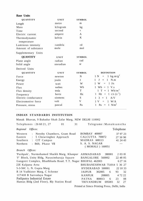
Base Units QUANTITY
Length Mass Time Electric current Thermodynamic
temperature Luminous intensity Amount of substance
Supplementary Units
QUANTITY Plane angle Solid angle
Derived Units
QUANTITY
Force Energy
Power Flux Flux density Frequency Electric conductance Electromotive force Pressure, stress
U N I T
metre
kilogram second ampere kelvin
candela mole
U N I T
radian steradian
U N I T
newton joule watt webes tesla hertz siemens volt pascal
SYMBOL
m
kg s
A K
cd mol
SYMBOL
rad sr
SYMBOL
N J W Wb T Hz S V Pa
DEFINITION
1 N = 1 kg.m/g2
1 J = 1 N.m 1 W = l J/s 1 Wb = 1 V.s
1 T = 1 Wb/m3
1 Hz = 1 c/s (s -1) 1 3 = 1 A/V 1 V = 1 W/A 1 Pa = 1 N/m2
INDIAN S T A N D A R D S INSTITUTION
Manak Bhavan, 9 Bahadur Shah Zafar Marg, NEW DELHI 110002
T e l e p h o n e s : 26 60 21, 27 01 31 T e l e g r a m e : M a n a k s a n s t h a
Regional Offices:
Western : Novelty Chambers, Grant Road Eastern : 5 Chowringhee Approach Southern : CIT Campus Northern : B69, Phase VII
Branch Offices:
'Pushpak ' , Nurmohamed Shaikh Marg, Khanpur 'F' Block, Unity Bldg, Narasimharaja Square Gangotri Complex, Bhadbhada Road. T.T. Nagar 22E Kalpana Area 5-3-56C L. N. Gupta Marg R 14 Yudhister Marg, C Scheme 117/418 B Sarvodaya Nagar Patliputra Industrial Estate Hantax Bldg (2nd Floor), Rly Station Road
BOMBAY 400007 CALCUTTA 700072 MADRAS 600113 S. A. S. NAGAR —
( MOHALI ) 160051
Telephone
37 97 23 27 50 90 41 24 43
AHMADABAD 380001 2 03 0l BANGALORE 560002 22 48 05 BHOPAL 462003 6 27 16 BHUBANESHWAR 751014 5 36 27 HYDERABAD 500001 22 10 33 JAIPUR 302005 6 93 32 KANPUR 208005 4 72 22 PATNA 800013 6 23 08 TRIVANDRUM 695001 32 27
Printed at Simco Printing Press, Delhi, India