Embed Size (px)
Citation preview

Disclosure to Promote the Right To Information
Whereas the Parliament of India has set out to provide a practical regime of right to information for citizens to secure access to information under the control of public authorities, in order to promote transparency and accountability in the working of every public authority, and whereas the attached publication of the Bureau of Indian Standards is of particular interest to the public, particularly disadvantaged communities and those engaged in the pursuit of education and knowledge, the attached public safety standard is made available to promote the timely dissemination of this information in an accurate manner to the public.
इंटरनेट मानक
“!ान $ एक न' भारत का +नम-ण”Satyanarayan Gangaram Pitroda
“Invent a New India Using Knowledge”
“प0रा1 को छोड न' 5 तरफ”Jawaharlal Nehru
“Step Out From the Old to the New”
“जान1 का अ+धकार, जी1 का अ+धकार”Mazdoor Kisan Shakti Sangathan
“The Right to Information, The Right to Live”
“!ान एक ऐसा खजाना > जो कभी च0राया नहB जा सकता है”Bhartṛhari—Nītiśatakam
“Knowledge is such a treasure which cannot be stolen”
“Invent a New India Using Knowledge”
है”ह”ह
IS 1930 (2003): Woodworking Tools - Chisels and Gouges [PGD6: Earth, Metal And Wood Working Hand Tools]


Is 1930:2003ISO 2729:1995
IW*I wik?-R-M@Fwlxiwi3( i%?7?7jpi%w)
Indian Standard
WOODWORKING TOOLS—CHISELS AND GOUGES
(Third Revision )
Ics 79.120.20
8
@ BIS 2003
BUREAU OF INDIAN STANDARDSMANAK BHAVAN, 9 BAHADUR SHAH ZAFAR MARG
NEW DELHI 110002
August 2003 Price Group 6

Woodworking Hand Tools Sectional Committee, BP 07
NATIONAL FOREWORD
This Indian Standard (Third Revision) which is identical with 1S0 2729:1995 ‘Woodworking tools—Chisels and gouges’ issued by the International Organization for Standardization (ISO), was adopted bythe Bureau of Indian Standards on the recommendations of the Woodworking Hand Tools SectionalCommittee and approval of the Basic and Production Engineering Division Council.
This Standard was first published in 1961 and since then it had undergone two revisions, the last (secondrevision) being in 1995. The above revisions were carried out by deriving necessary assistance fromISO 2729:1973.
ISO 2729 has been since then revised. In order to align with the work done at the international level, theSectional Committee dealing with the subject decided for this third revision by adopting ISO 2729:1995as an Indian Standard.
The text of the ISO Standard has been approved as suitable for publication as an Indian Standard withoutdeviations. Certain conventions are, however, not identical to those used in Indian Standards. Attention
is particularly drawn to the following:
a) Wherever the words ‘International Standard’ appear referring to this standard, they shouldbe read as ‘Indian Standard’.
b) Comma (,) has been used as a decimal marker in the International Standard while in IndianStandards, the current practice is to use a point (.) as the decimal marker.
For the purpose of deciding whether a particular requirement of this standard is complied with, the finalvalue, observed or calculated, expressing the result of a test or analysis shall be rounded off in accordancewith IS 2:1960 ‘Rules for rounding off numerical values (revise@ ’.The number of significant places retarnedin the rounded off value should be the same as that of the specified value in this standard.
IS 1930:2003ISO 2729:1995
Indian Standard
WOODWORKING TOOLS—CHISELS AND GOUGES
( Third Revision)
1 Scope
This International Standard specifies the characteristics of chisels and gouges for woodworking.
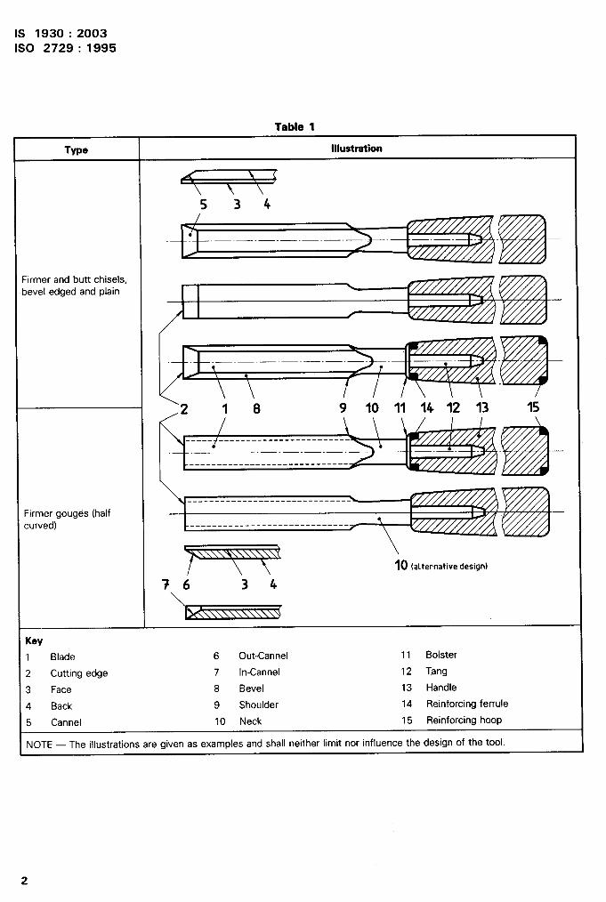
2 Nomenclature
See table 1.
1
IS 1930:2003ISO 2729:1995
Table 1----- .
Key
1 Blade 6 Out-Cannel 11 Bolster
2 Cutting edge 7 In-Cannel 12 Tang
3 Face 8 Bevel 13 Handle
4 Back 9 Shoulder 14 Reinforcing ferrule
5 Cannel 10 Neck 15 Reinforcing hoop
NOTE — The illustrations are given as examples and shall neither limit nor influence the design of the tool.
IS 1930:2003ISO 2729: 1995
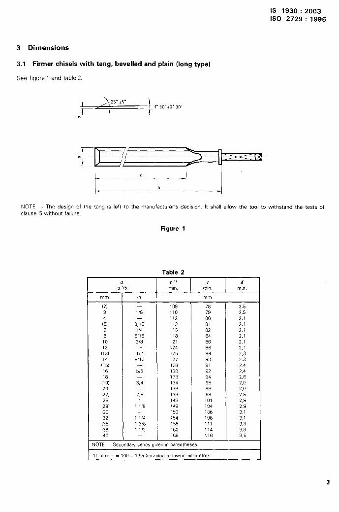
3 Dimensions
3.1 Firmer chisels with tang, bevelled and plain (long type)
See figure 1 and table 2.
.-’”’”’’””’”’
c 4 I
L b
NOTE — The design of the tang is left to the manufacturer’s decision. It shall allow the tool to withstand the tests of
clause 5 without failure.
Figure 1
Table 2.- —.- -
a b!) c d@ 15 mtn. min. mm
mm In mm,
(2) . 109 78 3,53 1/8 110 79 3,54 . 112 80 2,1(5) 3/16 113 81 2,16 1/4 115 82 2,18 5/16 118 84 2,110 3/8 121 86 2,112 — 124 88 2,1
(13) 1/2 125 89 2,39/16 127 90 2,3
(::) — 128 91 2,416 5/8 130 92 2,418 — 133 94 2,6
(19) 3/4 134 95 2,620 — 136 96 2,6(22) 7/8 139 98 2,825 1 143 101 2,9(28) 1 1/8 148 104 2,9(30) — 150 106 3,132 1 1/4 154 108 3,1(35) 1 3/8 158 111 3,3(38) 1 1/2 160 114 3,340 — 166 116 3,5
NOTE — Secondary series given m parentheses.
1) b mm = 106 + 1,5u (rounded to lower m!llfmetre).
3

IS 1930:2003ISO 2729:1995
3.2 Butt chisels with tang, bevelled and plain (short type)
See figure 2 and table 3.
m
c
1- b -1NOTE — The design of the tang is left to the manufacturer’s decision. It shall allow the tool to withstand the tests ofclause 5 without failure.
Figure 2
Table 3
a b c d
JS15 min. min. min.
mm in mm
6 1/4 104 76 2,1
10 3/8 107 76 2,1
(13) 1/2 109 76 2,3
16 5/8 111 76 2,4
(19) 3/4 113 76 2,6
25 1 118 76 2,9
32 1 1/4 122 76 3,1
(38) 1 1/2 127 76 3,1
50 2 135 76 3,5
NOTE — Secondav series is given in parentheses.
IS 1“930 :2003ISO 2729: 1995
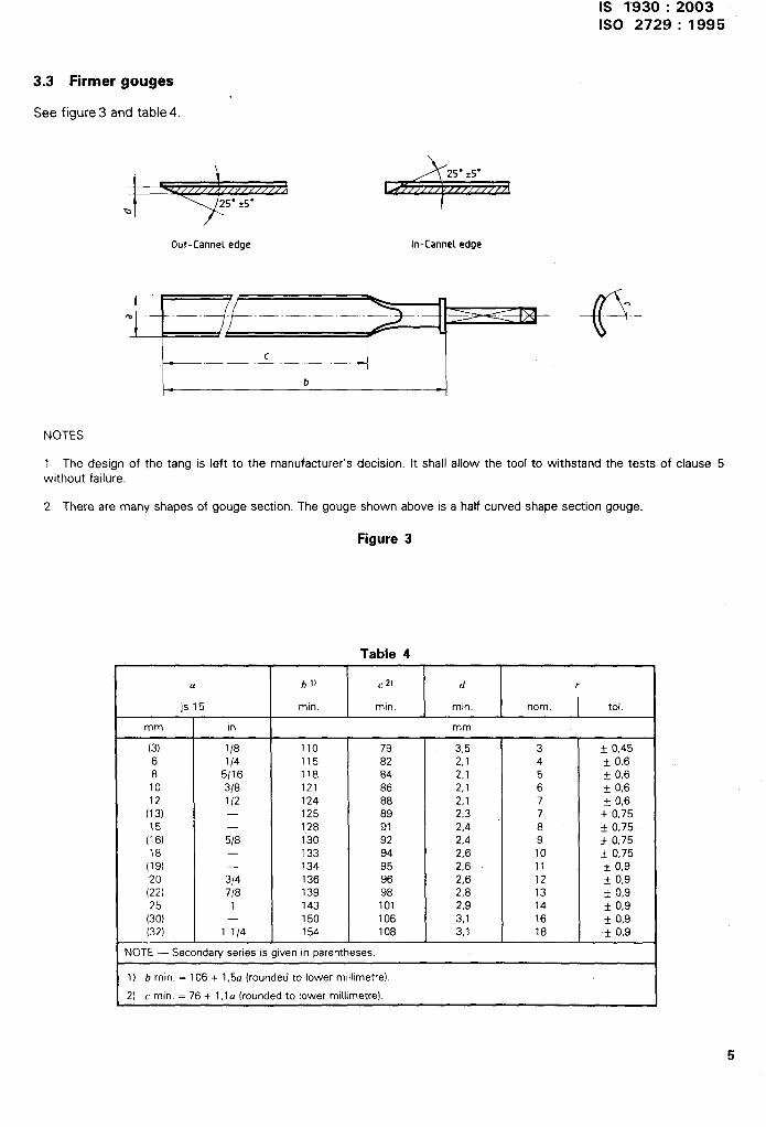
3.3 Firmer gouges
See figure 3 and table 4.
~t ,./////A/////////
Q
Out-Cannel edge
+
In-Cannel edge
@
.
NOTES
1 The design of the tang is left to the manufacturer’s decision. It shall allow the tool to withstand the tests of clause 5without failure.
2 There are many shapes of gouge section. The gouge shown above is a half cuwed shape section gouge
Figure 3
Table 41
a b 1) ~ 2) d r
js15 mm, mm, mm, nom. tot.
mm m mm
(3) 1/8 110 79 385 3 * 0,456 1/4 115 82 2,1 48
k 0,65/16 118 84 2,1 5
10+ 0,6
3/8 121 86 2,1 612
k 0,61/2 124 88 2,1 7 ~ 0,6
(13) — 125 89 2,3 7 * 0,7515 . 128 91 2,4 8 * 0,75
(16) 5/8 130 92 2,4 918
+ 0,75— 133 94 2,6 10 * 0,75
(19) — 134 95 2,6 1120
* 0,93/4 136 96 2,6 12 * 0,9
(22) 7/8 139 98 2,8 1325
* 0,91 143 101 2,9 14 * 0,9
(30) — 150 106 3,1 16 + 0,9(32) 1 1/4 154 108 3,1 18 * 0,9
NOTE — Secondary series IS given m parentheses.
1) b mm. = 106 + 1,5u (rounded to lower mfll!metre).
2) c min. = 76 + 1,1a (rounded to lower millimetre).
5

IS 1930:2003ISO 2729:1995
4 Technical specifications
4.1 Blade
The chisels and gouges shall have dimensions in conformity with those shown inshapes and dimensions shall be such that the tools can withstand loads to whichnormal use.
4.1.1 Material
3:1 to 3.3. The non-specifiedthey will be subjected during
The blades of chisels and gouges specified in this International Standard shall be manufactured from a materialwhich, taking into account the stated hardness, gives a cutting edge quality the same as, or greater than tool steelwith an analysis given in table 5 (for guidance only).
Table 5
Limit c “Si Mn P s
min. 0,90 Yo 0,15 Y. 0,25 % — —
max. 1,25 % 0,25 % 0,40 ‘YO 0,035 % 0,035 Yo
After heat treatment, the blades shall have a hardness of 55 HRC to 61 HRC ‘for a s 8 mm and 58 HRC to61 HRC for a >8 mm. This hardrless is valid at a minimum distance equal to 2/3 of length c measured from thecutting edge.
4.1.2 Cutting edge
The cutting edge shall be ground sharp and ready for final honing. The edge shall be at 900 to the centre line ofthe blade.
4.1.3 Bolster and neck
The bolster and neck shall be concentric with the centre line of the blade, and shall have such a formthey give goad support to the handle. It shall not have sharp corners that can damage the handle.
4.1.4 Tang
and size that
The tang shall have a shape which provides a good fit in the handle. It shall be of such a design as to withstandloading in normal use, without failure. It shall be concentric with the axis of the blade.
4.1.5 Finish
For chisels and gouges, the face, back and sides of the blade shall be finely ground or have an equivalent finish.
a) For the out-cannel edge gouges, the face shall be finely ground or have an equivalent finish.
b) For the in-cannel edge gouges, the back shall be finely ground or have an equivalent finish.
After finishing, a suitable protection shall be applied to prevent rusting.
6

IS 1930:2003ISO 2729:1995
4.2 Handle
4.2.1 Shape
The handle shall be designed to give a good grip. It shall not have sharp corners or irregularities which might behazardous during use. The dimensions of the handle shall be in proportion to those of the blade in order that the
tool be well balanced.
4.2.2 Material
The handle shall be made from a material having ttre necessary strength to withstand impact and bending loadsduring normal use. Wooden handles for tanged tools may have a reinforcing hoop.
4.2.3 Handle fixing to blade
The handle shall be securely attached to the blade and shall withstand the tests specified in clause 5.
5 Test methods
5.1 Blade
5.1.1 Test for soundness
Every blade shall be capable of passing the following test for soundness, at the completion of which it shall showno sign of fracture or flaw.
A suitable block of lead shall be placed on a bench or table. The blade shall be held by tang or neck, between thethumb and fingers; the hand shall then be raised and brought down quickly, using the force of wrist and elbow tostrike the flat of the blade a sharp blow against the top face of the lead block. This manually applied sharp blowshall be repeated six times consecutively.
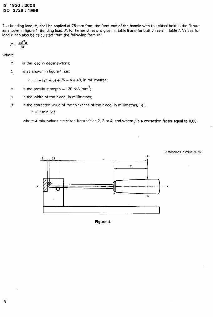
5.1.2 Bending test (chisels, see figure 4)
To determine the permanent deflection of the chisel blade, the distance between the fixture base and two points
A and B on the chisel are measured before and after applying the load in accordance with tables 6 and 7.
The deflection is measured by using an indicator clock or other suitable measuring intrument. The permanent de-flection is calculated as the difference between the two readings. The maximum permanent deflection allowed is1 mm at point A and 3 mm at point B.
The measuring points shall be located as follows:
A, at the highest point of the bolster;
B, 75 mm from the front end of the handle.
IS 1930:2003ISO ‘2729 :1995
The bending load, P, shall be applied at 75 mm from the front end of the handle with the chisel held in the fixtureas shown in figure 4. Bending load, P, for firmer chisels is given in table 6 and for butt chisels in table 7. Values forload P can also be calculated from the following formula:
ad’2u
‘= 6L
where
P is the load in decanewtons;
L is .as shown in figure 4, i.e.:
L = b – (21 + 5) + 75 = b + 49, in millimetres;
o is the tensile strength = 120 daN/mm2;
a is the width of the blade, in millimetres;
d’ is the corrected value of the thickness of the blade, in millimetres, i.e..
d’ =d min. x~
where d min. values are taken from tables 2, 3 or 4, and where~ is a correction factor equal to 0,88,
Dlmenstons m millimetres
5 21 LP
1-75
Figure 4
8
IS 1930:2003ISO 2729:1995
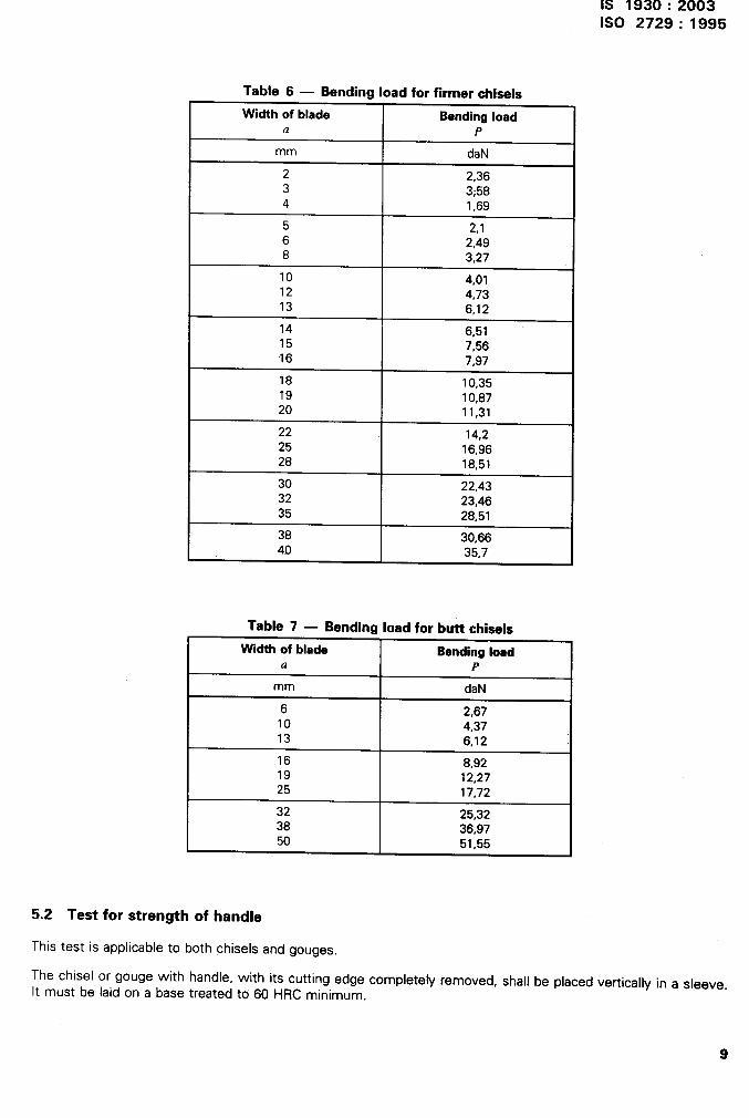
Table 6 — Bending load for firmer chisels
Width of blade Bendingload 1a P
mm daN
2 2,363 3,584 1,69
5 2,16 2,498 3,27
10 4,0112 4,7313 6,12
14 6.5115 7;5616 7,97
18 1083519 10,8720 11,31
22 14,225 16,9628 18,51
30 22,4332 23.4635 28;51
38 30,66
I 40 35,7I
Table 7 — Bending load for butt chisels
Width of blade Bendingloada P
mm daN
6 2,6710 4,3713 6,12
‘16 8,9219 12.2725 17;72
32 25,3238 36,9750 51.55
5.2 Test for strength of handle
This test is applicable to both chisels and gouges.
The chisel or gouge with handle, with its cutting edge completely removed, shall be placed vertically in a sleeve.It must be laid on a base treated to 60 HRC minimum.
9

IS 1930:2003ISO 2729: 1995
A metal weight of 5kgwith aflatface shall fall freely onto thehandle froma height. Values forthe height dropH, according tothe width of blade, are given intable8.
The weight shall be guided during the drop,
The chisel (gouge) handle, although it may show deformation in the shape of a mushroom on its end, shall still
be perfectly usable after the required number of blows given in table 8; that is to say, the handle shall neither splitnor break and the reinforcing hoop, if fitted, shall still be in place,
For guidance, the sleeve may be manufactured as indicated in figure 5.
NOTE 1 When testing a plastic handle, the frequency of blows from the machine may be reduced so has to cause no moreheating of the handle than would be caused by normal use in practice.
3---chiseL”ndes’es’iding s(eeve
se treated to minimalrdness of 60 HR[
Figure 5
10

After the impact test, the chisels
shall withstand the loads given [n
tests
.1S 1930:2003ISO 2729: 1995
and gouges shall be subjected to an axial pull-off test and a torsional test and
table 8 There shall be no [ndlcatron of any looseness of the handle after these
Table 8
Width of the t Height ofblade Corresponding
Proof load fordrop handle/blade
Handle/blade proofNumber of energy
<1 H pull-apart torqueblows
mn3 m J N Nm
(1 10 0,2 12 120 800 10
10. [/-20 0,3 12 180 1 000 10
(/ . 20 0,4 :2 240 1 200 10
11
Bureau of Indian Standards
BIS is a statutory institution established under the Bureau of Indian Standards Act, 1986 to promote
harmonious development of the activities of standardization, marking and quality certification of
goods and attendingto connected matters in the country.
Copyright
BIS has the copyright of all its publications. No part of these publications may be reproduced in any
form without the prior permission in writing of BIS. This does not preclude the free use, in the course
of implementing the standard, of necessary details, such as symbols and sizes, type or grade
designations. Enquiries relating to copyright be addressed to the Director (Publication), BIS.
Review of Indian Standards
Amendments are issued to standards as the need arises on the basis of comments. Standards are also
reviewed periodically; a standard along with amendments is reaffirmed when such review indicates that
no changes are needed; if the review indicates that changes are needed, it is taken up for revision.
Users of Indian Standards should ascertain that they are in possession of the latest amendments or
edition by referring to the latest issue of ‘BIS Catalogue’ and ‘Standards: Monthly-Additions’.
This Indian Standard has been developed from DOC: No. Bp 07 (0309).
Amendments Issued Since Publication
Amend No. Date of Issue Text Affected
BUREAU OF INDIAN STANDARDS
Headquarters:
Manak Bhavan, 9 Bahadur Shah Zafar Marg, New Delhi 110002 Telegrams: ManaksansthaTelephones: 3230131,3233375,3239402 (Common to all offices)
Regional Offices: Telephone
Central :
Eastern :
Northern :
Southern :
Western :
Branches :
Manak Bhavan, 9 Bahadur Shah Zafar Marg 3237617,3233841NEW DELHI 110002
1/1 4 C.I.T. Scheme Vll M, V.I.P. Road, Kankurgachi{
3378499,3378561KOLKATA 700054 3378626,3379120
SCO 335-336, Sector 34-A, CHANDIGARH 1“60022{
603843602025
C.I.T. Campus, lVCross Road, CHENNAI 600113{
2541216,25414422542519,2541315
Manakalaya, E9 MlDC, Marol, Andheri (East){
8329295,8327858MUMBAI 400093 8327891, 8327892
AHMEDABAD. BANGALORE. BHOPAL. BHUBANESHWAR. COIMBATORE. FARIDABAD.
GHAZIABAD. GUWAHATI. HYDERABAD. JAIPUR. KANPUR. LUCKNOW. NAGPUR.
NALAGARH. PATNA. PUNE. RAJKOT. THIRUVANANTHAPURAM. VISAKHAPATNAM.
Printed at Simco Printing Press, Oelhi
...