Embed Size (px)
Citation preview

Disclosure to Promote the Right To Information
Whereas the Parliament of India has set out to provide a practical regime of right to information for citizens to secure access to information under the control of public authorities, in order to promote transparency and accountability in the working of every public authority, and whereas the attached publication of the Bureau of Indian Standards is of particular interest to the public, particularly disadvantaged communities and those engaged in the pursuit of education and knowledge, the attached public safety standard is made available to promote the timely dissemination of this information in an accurate manner to the public.
इंटरनेट मानक
“!ान $ एक न' भारत का +नम-ण”Satyanarayan Gangaram Pitroda
“Invent a New India Using Knowledge”
“प0रा1 को छोड न' 5 तरफ”Jawaharlal Nehru
“Step Out From the Old to the New”
“जान1 का अ+धकार, जी1 का अ+धकार”Mazdoor Kisan Shakti Sangathan
“The Right to Information, The Right to Live”
“!ान एक ऐसा खजाना > जो कभी च0राया नहB जा सकता है”Bhartṛhari—Nītiśatakam
“Knowledge is such a treasure which cannot be stolen”
“Invent a New India Using Knowledge”
है”ह”ह
IS 14458 (Part 2) (1997, Reaffirmed 2007): Retaining Wallfor Hill Area--Guidelines, Part 2: Design ofRetaining/Breast Walls. ICS 93.020

(Reaffirmed 2007) IS 14458 (Part 2) : 1997
( Reaffirmed 2002 )
qC;I$l ~ c5T R2:~~1 Rcll~ - ~ Bl~GI \f(1l 2 Rlftttl~ ~ ~ f!\JfI~~
_Indian Standard
RETAINING WALL FOR HILL AREAGUIDELINES
October 1997
PART 2 DESIGN OF RETAINING/BREAST WALLS
ICS 93.020
© BIS 1997
BUREAU OF INDIAN STANDARDS MANAK BHAVAN, 9 BAHADUR SHAH ZAFAR MARG
NEW DELHI 110002
Price Group 4
Hill Area Development Engineering Sectional Committee, CED 56
FOREWORD
This Indian Standard was adopted by the Bureau of Indian Standards, after the draft finalized by the ·Hill Area Development Engineering Sectional Committee had been approved by the Civil Engineering Division Council.
Retaining wall is a structure used to retain backfill and maintain difference in the elevation of the two ground surfaces. Retaining wall may be effectively utilized to tackle the problem of landslide in hill area by stabilizing the fill slopes and cut slopes.
From the initial construction cost considerations, one metre of extra width in filling, requiring retaining walls, costs much more than constructing the same width by cutting inside the hill. Similarly the cost of a breast wall is several times more than a non-walled cut slope. However, considering maintenance cost, progressive slope instability and environmental degradation from unprotected heavy excavations, the use of retaining walls on hill roads and terraces becomes-essential. This standard (Part 2) is, therefore, being formulated to provide necessary guidance in design afretaininglbreast walls for stability of hill slopes, the other parts of the code being as follows which are under preparation:
Part 1 Part 3 Part 4 Part 5 Part 6 Part 7 Part 8 Part 9 Part 10
Selection of type of wall, Constr_uction of dry stone walls, Construction of banded dry stone walls, Construction of cement stone walls, Construction of gabion walls, Construction of RCC crib walls, Construction of timber crib walls, Design of RCC cantilever wall/buttressed walls!L-type walls, and Design and construction of reinforced earth retaining walls.
In the formulation of this standard, assistance has been derived from Mountain Risk Engineering Handbook.
The composition of technical committee responsible for the formulation of this standard is given at AnnexB.
For the purpose of deciding whether a particular requirement of this standard is complied with the final value, observed or calculated, expressing the result of a test or analysis shall be rounded off in accordance with IS 2 : 1960 'Rules for rounding off numerical values (revised)'. The number of significant places retained in the rounded off value should be the same as that of the specified value in this standard.
IS 14458 (Part 2) : 1997
Indian Standard
RETAINING WALL FOR HILL AREAGUIDELINES
PART 2 DESIGN OF RETAINING/BREAST WALLS
1 SCOPE
This standard (Part 2) deals with design of gravity type structures used to support earth or other materials behind them which would othelWise not stay in that position. Other types ofretainingstruclures are covered in Part 9 and Part 10 of this standard (under preparation)
2 REFERENCES
The Indian Standards listed in Annex A contain provisions which through reference in this text, constitute provision of this standard. At the time of publication, the editions indicated were valid. All standards are subject to revision, and parties to agreements based on this standard are encouraged to investigate the possibility of applying the most recent editions of the standards indicated in Annex A.
3 GENERAL
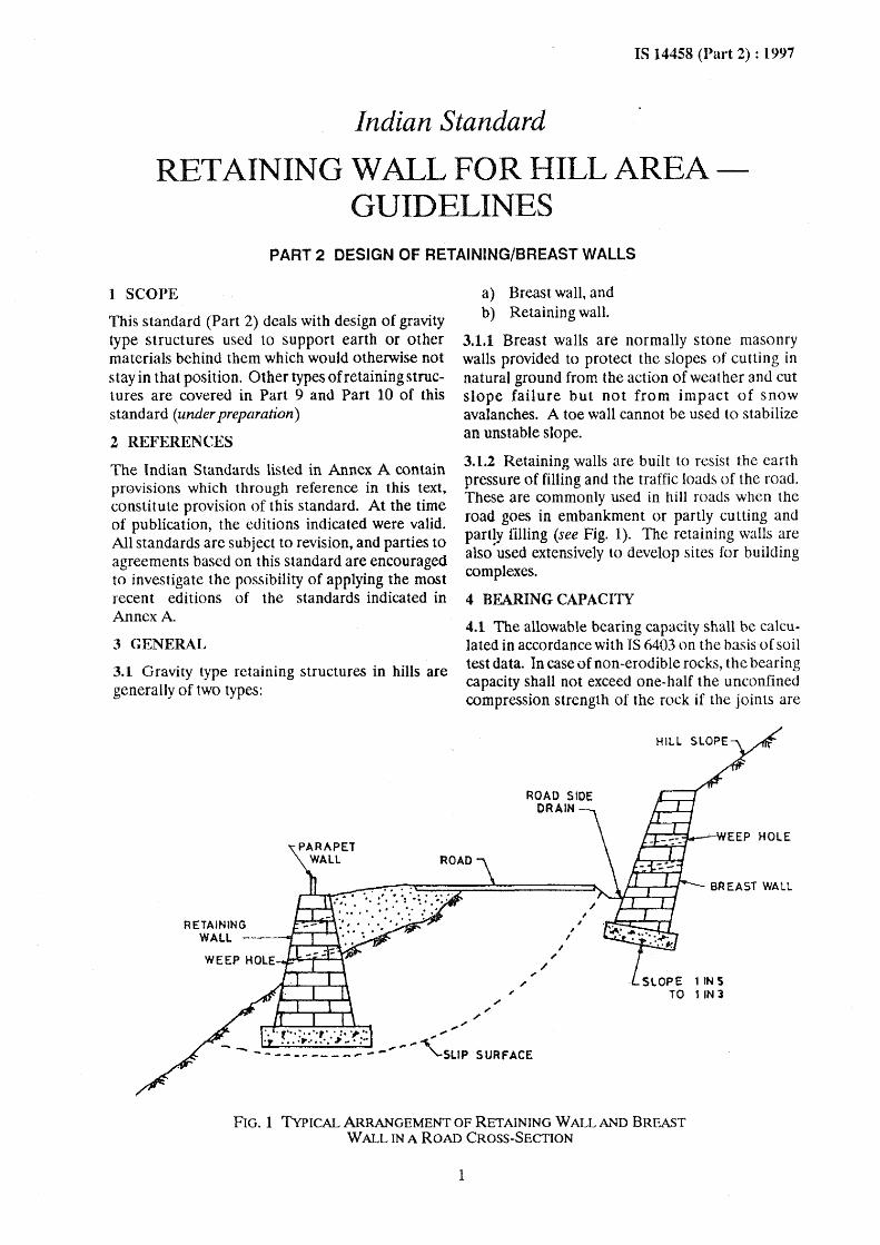
3.1 Gravity type retaining structures in hills are generally of two types:
RETAINING WALL ---.J-"l~
a) Breast wall, and b) Retaining wall.
3.1.1 Breast walls are normally stone masonry walls provided to protect the slopes of cutting in natural ground from the action of weather and cut slope failure but not from impact of snow avalanches. A toe wa1l cannot be used to stabilize an unstable slope.
3.1.2 Retaining walls are built to resist the earth pressure of filling and the traffic loads of the road. These are commonly used in hill roads when the road goes in embankment or partly cutting and partly filling (see Fig. 1). The retaining walls are also'used extensively to develop sites for building complexes.
4 BEARING CAPACITI
4.1 The allowable bearing capacity shall be calculated in accordance with IS 6403 on the basiso[ soil test data. In case of non-erodible rocks, the bearing capacity shall not exceed one-half the unconfined compression strength of the rock if the joints are
" / .,.
, I
I I ,
llNS liN 3
'. . {'" ' .. '.,. . : .. ,... ",. ,," . . .. : ...... '," ~. :.. ...",-' ---..... ,~
----------- ... - SLIP SURFACE
FIG. 1 TYPICAL ARRANGEMENT OF RETAINING WALL AND BREAST WALL IN A ROAD CROSS-SECTION
1
IS 14458 (Part 2) : 1997
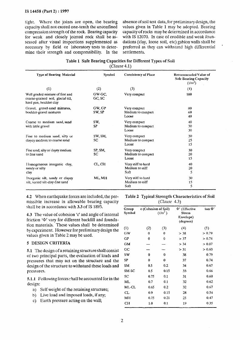
tight. Where the joints are open, the bearing capacity shall not exceed one-tenth the unconfined compression strength of the rock. Bearing capacity for weak and closely jointed rock shall be assessed after visual inspections supplemented as necessary by field or laboratory tests to determine their strength and compressibility. In the
absence of soil test data, for preliminary design, the values given in Table 1 may be adopted. Bearing capacity of rocks may be determined in accordance with IS 12070. In case of erodible and weak foundations (clay, loose soil, etc) gabion walls shall be preferred as they can withstand high differential settlements.
Table 1 Safe Bearing Capacities for Different Types·of Soil (Clause 4.1)
Type of Bearing Material Symbol Consistency of Place Recommended Value of Safe Bearing C~lpadty
(11m2)
(1) (2) (3) (4)
Well graded mixture of fine and GW-GC, Very compact 100 coarse-grained soil, glacial till, OC,SC hard pan, boulder clay
Gravel, gravel-sand mixtures, GW,GP Very compact 80 boulder-gravel mixtures SW,SP Medium to compact 60
Loose 40
Coarse to medium sand, sand SW, Very compact 40 with little gravel SP Medium to compact 30
Loose 30
Fine to medium sand, silty or SW,SM, Very com pact 30 clayey medium to coarse sand SC Medium to compact 25
Loose 15
Fine sa nd, silty or "clayey medium SP,SM, Very compact 30 to fine sand SC Medium to compact 20
Loose 15
I lomogeneous inorganic clay, CL,CH Very stiff to hard 40 sandy or silty Medium to stiff 20 clay Soft 5
Inorganic silt, sandy or clayey ML,MH Very stiff 10 hard 30 silt, varied silt-clay-fine sand Medium to stiff 15
Soft 5
4.2 When earthquake forces are included, the per- Table 2 Typical Strength Characteristics of Soil missible increase in allowable bearing capacity (Clause 4.3) shall be in accordance with 3.3 of IS 1893. Group c (Cohesion of Soil) ¢I' (Effective tan <1>'
4.3 The val ue of cohesion 'c' and angle of internal Symbol (t/m2 ) Stress
friction '<1>' vary for different backfill and founda-Envelope) (degrees)
tion materials. These values shall be determined (5)
by experiment. However for preliminary design the (1) (2) (3) (4)
values given in Table 2 may be used. GW 0 0 > 38 > 0.79
GP 0 0 > 37 > 0.74 5 DESIGN CRITERIA OM > 34 > 0.87
5.1 The design of a retaining structure shall consist GC > 31 > 0.60
of two principal parts, the evaluation of loads and sw 0 0 38 0.79
pressures that may act on the structure and the SP 0 0 37 0.74
design of the structure to withstand these loads and SM 0.5 0.2 34 0.67
pressures. SM-SC 0.5 0.15 33 0.66
5.1.1 Following forces fhall be accounted for in the sc 0.75 0.1 31 0.60
ML 0.7 0.1 32 0.62 design:
ML-CL 0.65 0.2 32 0.67 a) Self weight of the retaining structure;
CL 0.9 0.15 28 0.54 b) Live load and imposed loads, if any;
MH 0.75 0.21 25 0.47 c) -Earth pressure acting on the wall;
CH 1.0 0.1 19 0.35
2
d) Water pressure due to water table/subsurface seepage;
e) Water pressure due to water table on toe side, if any;
1) Seismic forces; and g) Special loads, if any.
The self weight of the structure, and live and imposed loads shall be estimated in accordance with IS 875 (Parts 1 to 5). In the usual cases live ~oad may be taken between 250 kg/m2 to 500 kg/m on the top width of the wall.
The earth pressures and other seismic forces on the retaining structure shall be estimated in accordance with IS 1893. For low volume roads, the walls may nOl be designed for earthquake forces. In case of retaining walls for roads earth pressure due to sur· Charge shall be in accordance with IRe Codes.
The consideration of full water pressure behind the wall may lead to quite heavy section. Adequate arrangement for release of this water pressure shall be made. Atleast 30 percent water pressure shall always be considered even in case of provision of good efficient pressure release system.
5.2 Retaining walls and breast walls shall be designed as rigid walls, using following criteria:
a) Factor of > 2.0 (static loads) safety > 1.5 (with (see also against earthquake IS 1904) overturning forces)
b) Factor of safety > 1.5 (static loads) against sliding > 1.0 (with earth
quake forces)
NOTE - The live loads and imposed loads adding to stability of the structure shall not be considered in working out the factors of safety given in 5.2(a) and S.2(b).
c) Maximum base :s qa (allowable bearing pressure capacity)
:5 1.33 qa (during earth-quake)
d) Minimum base> 0 (zero)) pressure
c) Factor of safety > 1.25 against floatation
[see also IS 4247 (Part 3)]
1) In case of steep hills, the factors of safety for slip surface below foundation shall be greater than 1.5 and 1.0 in static and seismic conditions respectively.
The design of wall foundations shall meet the requirements of IS 1080 and IS 1904.
5.3 Sometimes, to achieve the minimum factor of safety given in S.2(b) and thereby resist sliding it may be necessary to increase the base area or to add
3
IS 14458 (Part 2) : 1997
concrete keys monolithic with foundation slab or to provide piles.
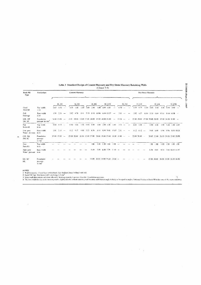
5.4 It is generally not possible to design each and every wall along the entire length of a road. Standard designs as -given in Table 3 may be adopted for walls less than 8 m in height and 120 m2 area in a low hazard zone provided the allowable bearing capacity is more than the maximum pressure indicated in the table.
6 OTHER DETAILS
6.1 Depth of Walls
The depth of retaining wall and breast wall below ground level or terrace level shaH be at least 500 mm below side drain within soil or highly jointed rock and foundation shall be on natural firm ground. All multiple breast walls shall be taken to the firm rock surface.
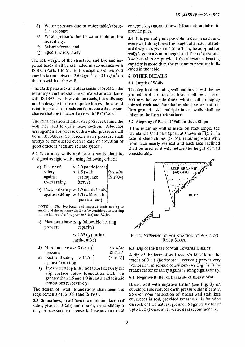
6.2 Stepping of Base of Wall on Rock Slope
If the retaining wall is made on rock slope, the foundation shall be stepped as shown in Fig. 2. In case of steep slopes (>35°), retaining walls with front face nearly vertical and back-face inclined shall be used as it will reduce the height of wall considerably,
: II ., .... ;: ..... .' ,. ," .... .., • .......;.
:.' SELF OR).INftfG··· . . ' BACK-FILL : . '. ", ... J
If"
ROCK
FIG. 2 STEPPING OF FOUNDATION OF WALL ON ROCK SLOPE
6.3 Dip of the Base of Wall Towards HHlside
A dip of the base of wall towards hillside to the extent of 3 : 1 (horizontal: vertical) proves very economical in seismic conditions (see Fig. 3). It increases factor of safety against sliding significantly.
6.4 Negative Batter of Backside of Breast Wall
Breast wall with negative batter (see Fig. 3) on cut-Slope side reduces earth pressure significantly. So even nominal section of breast wall stabilizes cut slopes in soil, provided breast wall is founded on rock or firm natural ground. Negative batter of upto 1 : 3 (horizontal: vertical) is recomnlendcd.
....
Back Fill Type
Good Back·fill
Full Drainage
GW, GP 'SW, Sp ------Fair Hack·fill
Low pore Water pre'"ufc
GM. SM SM, SC
Particular.;
Tn" ,,,idth itlll1
[lase width in m
Foundation pressure in tIm'
Top width in III
Ba,c \\ idth
Fountialinn
~res~u;e
tnt/m" ---------.-. .. -~ 1>00" Top width Back·till in III
High port' !:lase width Water pr~s,urc
GC, SC Foull(btion ML pressure
in t/m2
NOTES
Table J Standard Design of Cement Masonry and Dry Stone Masonry Retaining Walls (Clause 5.4)
Ht ),YI ~ 0.05 070 ._-
1.91 2.01
101.00 J:1.fJO
Cement Masonry
III (,M Ht 8M Ht 10M ,----A-----. ~ ,,.----'''----. 0.75 1.00 1.00 O.~O 1.00 1.00 (l.90 1.00
3.920g gell 'i1.l 8.10 10.96 1i.64Ll.57
2'i.O 20.0() IlJX) 3:1.00 20.00 17.00 40.0021.00
Dry Stone Masonry
r-______________ -JA~_________~
lit :lM Ht ('~l lit ~M lIt 101\1 ,..---A---, ~ ~ ~
070 075 095 100 D.SS I.OD I.(X) O')(J 1.00
2.01 J.n 4 . .\2 850 5.~.l ()8~ I i .~J 6.64 14.58
1100 - .. noo 20.00 17.00 29.00 20.00 I3.iJO .16 ()O 16.00
..... _-----_ ... ---.-.. _._- ----------0.60 0.7.'\ 0.90 1.00 I 00 09., 1.01) UK) 1.00 UK) 1.00 t) 75 0.~5 100 1.00 1.00 UXJ I.O(J 1.00 1.00
I.~I 2.11 -1.12 447 HR -' '\1 I> 5'J X 14 6.9-1 9.<;(J 1401 ~.II 4.12U2 5.63 649 1>.'14 (i'14 X.50 10.20
1'i.OO 13.00 25.00 22.00 20.0() )200 25.00 20.00 39.00 25.00 11.00 II 00 non 20.00 -. 2X.OO noo 2{),OO JH)O 2'i.00 20.00
---------------._ .... _ ...... --1.00 LtXJ 1.00 1.00 1.00 1.00 1.00 1.00 1.00 1.00 1.00
6.49 7.89 8.50 7.79 11.01 - 654 865 R.70 nH 10.11 11.<)7
22.00 20.00 19.00 2').00 21.00 - 2200 10.00 Ib.OO 25.00 20.00 18.00
I Wall Geometry: Front face venical back, face inclined, base inclined with hill. 2 Hack Fill Top: Horizontal "ith surcharge 1.51/111'. 3 Select wall dimensions ,uel! that alklw"bl" hearing capacity is greater than the founr.lation pressure. -l The base width for dry $[one mason ry \\,,11 is slightly less for cementlllasonrywall because wall friction angle is likely to he equal to angle of internal friction of back fill in the case of dry slone masonry
I~ /~
IS 14458 (Part 2) : 1997
300 mm LAYER OF SILTY SOIL WITH BOULDER TO PREVENT INGRESS OF RAIN WATER
SLOPE 1 IN 5
SLOPE 1 IN 5 TO 1 'IN 3
CATCH DRAIN
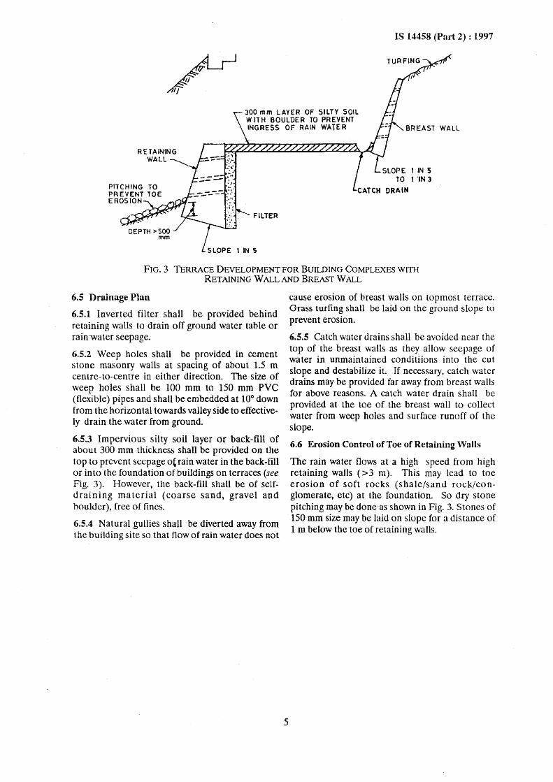
FIG. 3 TERRACE DEVELOPMENT FOR BUILDING COMPLEXES WIlli RETAINING WALLAND BREAST WALL
6.5 Drainage Plan
6.5.1 Inverted filter shall be provided behind retaining walls to drain off ground water table or rain-water seepage.
6.5.2 Weep holes shall be provided in cement stone masonry walls at spacing of about 1.5 m centre-to-centre in -either direction. The size of weep holes shall be 100 mm to 150 mm PVC (flexible) pipes and shall be embedded at 10° down from the horizontal towards valley side to effectively drain the water from ground.
6.5.3 Impervious silty soil layer or back-fill of about 300 mm thickness shall be provided on the top to prevent seepage 0' rain water in the back-fill or into the foundation of buildings on terraces (see Fig. 3). However, the back-fill shall be of selfdraining material (coarse sand, gravel and boulder), free of fines.
6.5.4 Natural gullies shall be diverted away from the building site so that flow of rain water does not
5
cause erosion of breast walls on topmost terrace. Grass turfing shall be laid on the ground slope to prevent erosion.
6.5.5 Catch water drains shall be avoided ncar the top of the breast walls as they allow seepage of water in unmaintained conditiions into the cut slope and destabilize it. If necessary, catch water drains may be provided far away from breast walls for above reasons. A catch water drain shall be provided at the toe of the breast wall to collect water from weep holes and surface runoff of the slope.
6.6 Erosion Control of Toe of Retaining Walls
The rain water flows at a high speed from high retaining walls (> 3 m). This may lead to toe erosion of soft rocks (shale/sand rock/conglomerate, etc) at the foundation. So dry stone pitching may be done-as shown in Fig. 3. Stones of 150 mm size may be laid on slope for a dis tance of 1 m below the toe of retaining walls.
IS 14458 (Part 2) : 1997
ANNEXA
(Clause 2) LIST OF REFERRED INDIAN STANDARDS
IS No. Title
875 Code of practice for design loads (other than earthquake) for buildings and structures: .
(Part 1) : 1987 Dead loads - Unit weights of building material and stored rna terials (second revision)
(Part 2) : 1987 Imposed loads (second revision)
(Part 3) : 1987 Wind loads (second revision)
(Part 4) : 1987 Snow loads (second revision)
(Part 5) : 1987 Special loads and load combina-
1080: 1986
lions (second revision)
Code of practice for design and construction of shallow foundations on soils (other than raft, ring and shell) (second revision)
6
IS No.
1893: 1984
1904: 1986
Title
Criteria for earthquake resistant design of structures (fourth revision)
Code of practice for design and construction of foundations in soils: General rcquiremen ts (third revision)
4247 Code of practice for structural (Part 3) : 1978 design of surface hydel power
stations: Part 3 Substructure (first revision)
6403: 1981
12070: 1987
Code of practice for determination of bearing capacity of shallow foundations (first revision)
Code of practice for design and construction of shallow foundation on rock
IS 14458 (Part 2) : 1997
ANNEXB
(Foreword) COMMITTEE COMPOSITION
Hill Area Development Engineering Sectional Commi ttce, CED 56
Chainnan DR GorAL RANJAN
Members SHRI SHEIKH NAZIR AHMED
PROF A K. CHAKRAHORTY
SHRI R. C. LAKHERA (Alternate) CHAIRMAN-CUM-MANAGING DIRECTOR
SHRI B. B. KUMAR (Alternate) CHIEF ENGINEER (DAM DESIGN)
SUPTDG ENGJNEER (TEHRI DAM DESIGN
CIRCLE) (Alternate) CHIEF ENGINEER (ROADS)
SUPTDG ENGINEER (ROADS) (Alternate) DEPUTY DIRECTOR GENERAL
(D&S DTE, DGBR) DEPUTY SECRETAR Y (T), IRe (Alternate)
DIRECTOR, H CD (N & W) DIRECTOR (SARDAR SAROVAR) (Alternate)
DR R. K. DUBEY
DR D. S. UPADHYAY (Altemate) SHRI PAWAN KUMAR GUPTA
FIELD COORDINATOR (Alternate) SHRIT. N. GUPTA
SIlRI J. SENGUPTA (Alternate) SHRl M. M. HARBOLA
SHiU P. K. PATHAK (Alternate) DR U. C. KALn'A
SHRI B. C. BORTHAKUR (AlLernate) SHRI S. KAUL
SHRI KJREET KUMAR
PROF A K. MArfRA
PROF ARVIND KRIsHAN (Alternate) DR O. S. MEHROTRA
SHRI N. C. BHAGAT (Alternate) SHRI P. L. NARULA
SHRI S. DASGUP'TA (Alternate) SHRIMATI M. PARTHA'';ARATHY
SHRI N. K. BALI (Alternate) SHRI D. P. PRADHAN
SHRI P. JAGANNATI-IA RAO
SHRl D. S. TOLlA (Altemate) DRK. S. RAO
SHRl P. K. SAH
SHRI J. GOPALAKRISHNA (Alternate) SHRI G. S. SAINI
DR BHAWANI SINGH
DR P. C. JAIN (Alternate) SHRl BHOOP StNGH
SHRl R. D. SINGH
DR SUDHIR KUMAR (Alternate) PROF C. P. SINHA
SHRI D. K. SINGH (Alternate) SHRI LAKHBlR SINGH SONKHLA
DR P. SRINIVASULU
SHRI N. GOPALAKR1SHNAN (Alternate) SUPTDG SURVEYOR OF WORKS (NZ)
SURVEYOR OF WORKS - I (NZ) (Alternate)
Representing University of Roorkee, Roorkee
Public Works Department, Jammu & Kashmir
Indian Institute of Remote Sensing, Dehra Dun
National Buildings Construction Corporation, New Delhi
Uttar Pradesh Irrigation DesignOrganiz3tion, Roorkcc
Ministry of Surface Transport, New Delhi
Indian Roads Congress, New Delhi
Central Water Commission, New Delhi
Indian Meteorological Department, New Delhi
Society for Integrated Development of Himalayas, Mussorie
Building Materials and Technology Promotion Council, New Delhi
Forest Survey of India, Dehra Dun
Regional Research Laboratory, Jorhal
Ministry of Railways, New Delhi G.B. Pant Institute of Himalayan Environment and Development, Almonl School of Planning and Architecture, New Delhi
Central Building Research Institute, Roorkee
Geologi~J Survey of India, Calcutta
Engineer-in-Chiefs Branch, Anny Headquarters, New Delhi
Sikkim Hill Area Development Board, Gangtok Central Road Research Institute, New Delhi
lIT, New Delhi Directorate General Border Roads (D&S), New Delhi
Central Mining Research Institute, Dhanbad University of Roorkee, Roorkee
Department of Science and Technology, New Delhi National Institute of Hydrology, Roorkee
North-Eastern Regional Institute of Water and Land Management, Assam
Public Works Department, Simla Structural Engineering Research Centre, Madras
Central Public 'Works Department, New Delhi
(Continued on page 8)
7
IS 14458 (Part 2) : 1997
(Continued from page 7)
Members SHRI V. SURESH
SHRJ D. P. SINGH (Allemare) SHRJ S. C. TIWARI
SHRI K. VENKATACI-iALAM
SHRl S. K BASBBAR (Alternate) DR N. S. VIRDHI
SHRI VINOD KUMAR,
Director (Civ Engg)
Represeming Housing and Urban Development Corporation (HUDCO), New Delhi
U.P. Hill Area Development Board, Lucknow Central Soil and Material Research Station, New Delhi
Wadia Institute of Himalayan Geology, Dehra Dun Director General, BIS (Ex-officio Member)
Member Secretaries
SHRI T. B. NARAYANAN
Joint Director (Civ Engg), BIS
SHRI SANJA Y PANT
Deputy Director (Civ Engg), B IS
8
Bureau of Indian Standards
BIS is a statutory institution established under the Bureau of Indian Standards Act, 1986 to promote harmonious development of the activities of standardization, marking and quality certification of goods and attending to connected matters in the country
Copyright
BIS has the copyright of aU its publications. No part of these publications may be reproduced in any form without the prior permission in writing of BIS. This does not preclude the free use, in the course of implementing the standard, of necessary details, such as symbols and sizes, type or grade designations. Enquiries relating to copyright be addressed to the Director (Publication), BIS.
Review of Indian Standards
Amendments are issued to standards as the need arises on the [,sis of commenL~. St.'lndards are also reviewcd periodically; a standard along with amendments is reaffirmed when such review indicatcs that no changes arc needed; if the review indicates that changes arc needed, it is taken up for revision. U;"crs of Indian Stand:uds should ascertain that they are in possession of the latest amcndmcnl~ or edition by referring to the lalest issue of 'BIS Handbook 9 and 'Standards.Monthly Additions'.
This Indian Standard has been developed from Doc: No. CHD56 (5546).
Amendments Issued Since Publication
Amend No. Date of Issue
, BUREAU OF INDIAN STANDARDS
Headquarters:
Manak Bhavan, 9 Bahadur Shah Zafar Marg, New Delhi 110002 Telephones: 32301 31,3233375,3239402
Regiona 1 Offices:
Central : Manak Bhavan, 9 Bahadur Shah Zafar Marg NEW DELHI 110002
Eastern : 1/14 C.I.T. Scheme VII M, V.I.P. Road, Maniktola CALCUTI A 700054
Northern : SCO 335-336, Sector 34~A, CHANDIGARH 160022
Southern C.lT. Campus, IV Cross Road, C!IENNAI 600113
Western Manakalaya, E9 MIDC, Marol, Andheri (East) MUMBAI 400093
Branches AHMADABAD. BANGALORE. BHOPAL. BHUBANESHWAR. COIMBATORE. FARIDABAD. GHAZlABAD. GUWAHATI. HYDERABAD. JAIPUR. KANPUR. LUCKNOW. NAGPUR. PATNA. PUNE. THIRUVANANTHAPURAM.
Text Affected
Telegrams: Manaksanstha (Common to all offices)
Telephone
32376 17,3233841
{ 3378499,3378561 33786 26, 33791 20
{60 38 43 602025
{ 23502 16, 2350442 235 15 19,23523 15
{ 83292 95, 832 78 58 832 78 91, 832 78 92
Printed at Simco Printing Press, Delhi,lndia