Embed Size (px)
Citation preview

Disclosure to Promote the Right To Information
Whereas the Parliament of India has set out to provide a practical regime of right to information for citizens to secure access to information under the control of public authorities, in order to promote transparency and accountability in the working of every public authority, and whereas the attached publication of the Bureau of Indian Standards is of particular interest to the public, particularly disadvantaged communities and those engaged in the pursuit of education and knowledge, the attached public safety standard is made available to promote the timely dissemination of this information in an accurate manner to the public.
इंटरनेट मानक
“!ान $ एक न' भारत का +नम-ण”Satyanarayan Gangaram Pitroda
“Invent a New India Using Knowledge”
“प0रा1 को छोड न' 5 तरफ”Jawaharlal Nehru
“Step Out From the Old to the New”
“जान1 का अ+धकार, जी1 का अ+धकार”Mazdoor Kisan Shakti Sangathan
“The Right to Information, The Right to Live”
“!ान एक ऐसा खजाना > जो कभी च0राया नहB जा सकता है”Bhartṛhari—Nītiśatakam
“Knowledge is such a treasure which cannot be stolen”
“Invent a New India Using Knowledge”
है”ह”ह
IS 13778-3 (2012): Winding wires - Test methods, Part 3:Mechnical Properties [ETD 33: Winding Wire]

© BIS 2012
August 2012 Price Group 12
B U R E A U O F I N D I A N S T A N D A R D SMANAK BHAVAN, 9 BAHADUR SHAH ZAFAR MARG
NEW DELHI 110002
Hkkjrh; ekud
os"Vu — ijh{k.k i¼fr;k¡Hkkx 3 ;kaf=kd xq.k&èkeZ
(igyk iqujh{k.k )
Indian StandardWINDING WIRES — TEST METHODS
PART 3 MECHANICAL PROPERTIES
( First Revision )
ICS 29.060.10
IS 13778 (Part 3) : 2012IEC 60851-3 : 2009
Winding Wires Sectional Committee, ETD 33
NATIONAL FOREWORD
This Indian Standard (Part 3) (First Revision) which is identical with IEC 60851-3 : 2009 ‘Windingwires — Test methods — Part 3: Mechanical properties’ issued by the International ElectrotechnicalCommission (IEC) was adopted by the Bureau of Indian Standards on the recommendation of theWinding Wires Sectional Committee and approval of the Electrotechnical Division Council.
This standard was first published in 1993. This revision has been undertaken with a view to bring it inline with the latest version of IEC 60851-3 : 2009
This standard is published in various parts. The other parts in this series are:
Part 1 GeneralPart 2 Determination of dimensionsPart 4 Chemical propertiesPart 5 Electrical propertiesPart 6 Thermal properties
The text of IEC Standard has been approved as suitable for publication as an Indian Standard withoutdeviations. Certain conventions are, however, not identical to those used in Indian Standards. Attentionis particularly drawn to the following:
a) Wherever the words ‘International Standard’ appear, referring to this standard, they should beread as ‘Indian Standard’.
b) Comma (,) has been used as a decimal marker while in Indian Standards, the current practiceis to use a point (.) as the decimal marker.
In this adopted standard, reference appears to certain International Standards for which IndianStandards also exist. The corresponding Indian Standards which are to be substituted in their respectiveplaces are listed below along with their degree of equivalence for the editions indicated:
International Standard Corresponding Indian Standard Degree of Equivalence
IEC 60851-1 Winding wires — Testmethods — Part 1: General
IEC 60851-2 : 1996 Winding wires —Test methods — Part 2:Determination of dimensions
IS 13778 (Part 1) : 2011 Windingwires — Test methods: Part 1General (first revision)IS 13778 (Part 2) : 1993 Windingwires — Test Methods: Part 2Determination of dimensions
Identical toIEC 60851-1 : 1996
Identical toIEC 60851-2 : 1985
The technical committee has reviewed the provision of the following International Standard referredin this adopted standard and has decided that it is acceptable for use in conjunction with this standard:
International Standard Title
ISO 178 : 2001 Plastics — Determination of flexural properties
For the purpose of deciding whether a particular requirement of this standard is complied with, thefinal value, observed or calculated expressing the result of a test, shall be rounded off in accordancewith IS 2 : 1960 ‘Rules for rounding off numerical values (revised)’. The number of significant placesretained in the rounded off value should be the same as that of the specified value in this standard.
1 Scope
This part of IEC 60851 specifies the following methods of test for winding wires:
– Test 6: Elongation; – Test 7: Springiness; – Test 8: Flexibility and adherence; – Test 11: Resistance to abrasion; – Test 18: Heat bonding.
For definitions, general notes on methods of test and the complete series of methods of test for winding wires, see IEC 60851-1.
2 Normative references
The following referenced documents are indispensable for the application of this document. For dated references, only the edition cited applies. For undated references, the latest edition of the referenced document (including any amendments) applies.
IEC 60851-1, Winding wires – Test methods – Part 1: General
IEC 60851-2:1996, Winding wires – Test methods – Part 2: Determination of dimensions
ISO 178:2001, Plastics – Determination of flexural properties Amendment 1:2004
3 Test 6: Elongation
3.1 Elongation at fracture
Elongation is the increase in length expressed as a percentage of the original length.
A straight piece of wire shall be elongated to the point of fracture of the conductor at a rate of (5 ± 1) mm/s with an elongation tester or with tensile testing equipment with a free measuring length of between 200 mm and 250 mm. The linear increase at fracture shall be calculated as a percentage of the free measuring length.
Three specimens shall be tested. The three single values shall be reported. The mean value represents elongation at fracture.
3.2 Tensile strength
Tensile strength is the ratio of the force at fracture to initial cross-section.
Indian StandardWINDING WIRES — TEST METHODS
PART 3 MECHANICAL PROPERTIES
( First Revision )
IS 13778 (Part 3) : 2012IEC 60851-3 : 2009
1
A straight piece of wire shall be elongated to the point of fracture of the conductor at a rate of (5 ± 1) mm/s with tensile testing equipment with a free measuring length of between 200 mm and 250 mm and which records the force at fracture.
Three specimens shall be tested. The initial cross-section and the three single values of the force at fracture shall be reported. The mean value of the ratio of the force at fracture and the initial cross-section represents the tensile strength.
4 Test 7: Springiness
Springiness is the recoil measured in degrees after the wire is wound in the form of a helical coil or bent through an angle.
4.1 Round wire with a nominal conductor diameter from 0,080 mm up to and including 1,600 mm
4.1.1 Principle
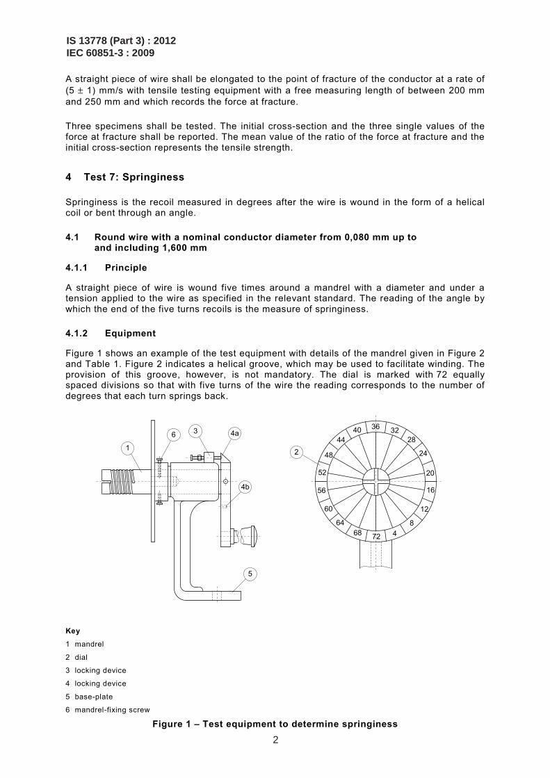
A straight piece of wire is wound five times around a mandrel with a diameter and under a tension applied to the wire as specified in the relevant standard. The reading of the angle by which the end of the five turns recoils is the measure of springiness.
4.1.2 Equipment
Figure 1 shows an example of the test equipment with details of the mandrel given in Figure 2 and Table 1. Figure 2 indicates a helical groove, which may be used to facilitate winding. The provision of this groove, however, is not mandatory. The dial is marked with 72 equally spaced divisions so that with five turns of the wire the reading corresponds to the number of degrees that each turn springs back.
3640
44
48
52
56
60
6468 72 4
8
12
16
20
24
28 32
1 2
3 6 4a
4b
5
Key
1 mandrel
2 dial
3 locking device
4 locking device
5 base-plate
6 mandrel-fixing screw
Figure 1 – Test equipment to determine springiness
IS 13778 (Part 3) : 2012IEC 60851-3 : 2009
2
1
2
d a b
c
e
f X
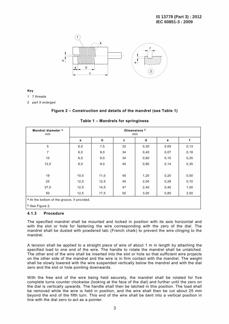
Key
1 7 threads
2 part X enlarged
Figure 2 – Construction and details of the mandrel (see Table 1)
Table 1 – Mandrels for springiness
Mandrel diameter a mm
Dimensions b mm
a b c d e f
5
7
10
12,5
19
25
37,5
50
6,0
6,0
6,0
6,0
10,0
12,5
12,5
12,5
7,5
9,0
9,0
9,0
11,0
12,5
14,5
17,5
32
34
34
40
45
45
47
50
0,30
0,40
0,60
0,80
1,20
2,00
2,40
3,00
0,05
0,07
0,10
0,14
0,20
0,28
0,40
0,80
0,13
0,18
0,25
0,35
0,50
0,70
1,00
2,00
a At the bottom of the groove, if provided.
b See Figure 2.
4.1.3 Procedure
The specified mandrel shall be mounted and locked in position with its axis horizontal and with the slot or hole for fastening the wire corresponding with the zero of the dial. The mandrel shall be dusted with powdered talc (French chalk) to prevent the wire clinging to the mandrel.
A tension shall be applied to a straight piece of wire of about 1 m in length by attaching the specified load to one end of the wire. The handle to rotate the mandrel shall be unlatched. The other end of the wire shall be inserted into the slot or hole so that sufficient wire projects on the other side of the mandrel and the wire is in firm contact with the mandrel. The weight shall be slowly lowered with the wire suspended vertically below the mandrel and with the dial zero and the slot or hole pointing downwards.
With the free end of the wire being held securely, the mandrel shall be rotated for five complete turns counter clockwise (looking at the face of the dial) and further until the zero on the dial is vertically upwards. The handle shall then be latched in this position. The load shall be removed while the wire is held in position, and the wire shall then be cut about 25 mm beyond the end of the fifth turn. This end of the wire shall be bent into a vertical position in line with the dial zero to act as a pointer.
IS 13778 (Part 3) : 2012IEC 60851-3 : 2009
3
A pencil or similar tool shall be placed to the left of this end of the wire to prevent any sudden springback. The coil shall then be allowed to unwind slowly and without jerking.
NOTE If the wire springs back suddenly, erroneous results may be obtained.
The mandrel and the dial shall then be unlatched and rotated clockwise to bring the pointer back into a vertical position. The springback angle is equal to the reading on the dial in line with the pointer. With very springy wires, the pointer may recoil more than one complete revolution. If this is the case, 72 has to be added to the dial reading for each complete revolution of recoil.
Three specimens shall be tested. The three single values shall be reported. The mean value represents springiness.
4.2 Round wire with a nominal conductor diameter over 1,600 mm and rectangular wire
4.2.1 Principle
A straight piece of wire shall be bent through an angle of 30°. After removing the force, the reading of the angle by which the wire springs back is the measure of springiness.
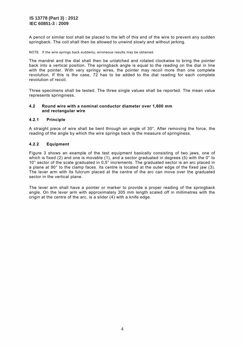
4.2.2 Equipment
Figure 3 shows an example of the test equipment basically consisting of two jaws, one of which is fixed (2) and one is movable (1), and a sector graduated in degrees (5) with the 0° to 10° sector of the scale graduated in 0,5° increments. The graduated sector is an arc placed in a plane at 90° to the clamp faces. Its centre is located at the outer edge of the fixed jaw (3). The lever arm with its fulcrum placed at the centre of the arc can move over the graduated sector in the vertical plane.
The lever arm shall have a pointer or marker to provide a proper reading of the springback angle. On the lever arm with approximately 305 mm length scaled off in millimetres with the origin at the centre of the arc, is a slider (4) with a knife edge.
IS 13778 (Part 3) : 2012IEC 60851-3 : 2009
4
0°
10°
20°
30°
Position 2
Position 1
1
2
3
6
4
5
R 0,5 mm
0°
20°
30°
Position 3
1
2
3
6
4
5
7
Key
1 moveable jaw
2 fixed jaw
3 centre of graduated sector
4 slider
5 graduated sector
6 wire specimen
7 sprinback
Figure 3 – Test equipment to determine springiness
4.2.3 Specimen
A wire sample of at least 1 200 mm in length shall be removed from the spool with as little bending of the wire as possible. It shall be straightened by hand and cut into three pieces each of 400 mm length. Elongation by tools shall not be used. Unnecessary bending shall be avoided to minimize work hardening.
4.2.4 Procedure
The conductor diameter or thickness, multiplied by 40, determines the position of the slider on the lever arm. The specimen shall be tightened between the jaws with a force just sufficient to
IS 13778 (Part 3) : 2012IEC 60851-3 : 2009
5
prevent slipping. The specimen shall be tightened in such a position as to allow bending the wire in the same direction as it was wound on the spool. The free end of the specimen shall exceed the slider knife edge by (12 ± 2) mm.
By means of the lever arm, starting at the initial position (the 30° scale mark, position 1), the wire shall be bent for 30° (the 0° scale mark, position 2). The total bending shall take between 2 s and 5 s. The specimen shall be held in this position for not more than 2 s and then returned in the reverse direction at the same angular rate at which it was bent, until the slider knife edge moves away from the wire specimen. The lever arm shall be raised again until the slider knife edge just contacts the wire specimen without bending it. In this position, the springback angle equals the reading on the scale of the graduated sector in line with the pointer on the lever arm (position 3).
Three specimens shall be tested. The single values shall be reported. The mean value represents springiness.
5 Test 8: Flexibility and adherence
Flexibility and adherence reflect the potential of the wire to withstand stretching, winding, bending or twisting without showing cracks or loss of adhesion of the insulation.
5.1 Mandrel winding test
5.1.1 Round wire
A straight piece of wire shall be wound for 10 continuous and adjacent turns around a polished mandrel of the diameter given in the relevant standard. The mandrel shall be rotated with a rate of 1 r/s to 3 r/s with a tension applied to the wire that is just sufficient to keep it in contact with the mandrel. Elongating or twisting the wire shall be avoided. Any suitable equipment shall be used.
5.1.1.1 Enamelled round wire with a nominal conductor diameter up to and including 1,600 mm
If the relevant standard calls for pre-stretching before winding, the wire shall be elongated according to Clause 3 to the specified percentage. After winding, the specimen shall be examined for cracks with the magnification as given in Table 2.
Table 2 – Magnification to detect cracks
Nominal conductor diameter mm
Magnification a
Over Up to and including
–
0,040
0,500
0,040
0,500
1,600
10 to 15 times
6 to 10 times
1 to 6 times
a One time expresses normal vision.
Three specimens shall be tested. Any cracks detected shall be reported.
5.1.1.2 Fibre covered round wire
After winding, the specimen shall be examined for exposure of the bare conductor with normal vision or with a magnification of up to six times.
IS 13778 (Part 3) : 2012IEC 60851-3 : 2009
6
Three specimens shall be tested. Exposure of the bare conductor shall be reported.
5.1.1.3 Fibre covered enamelled round wire
After winding, the specimen shall be examined for exposure of the bare conductor or underlying coating with normal vision or with a magnification of up to six times.
Three specimens shall be tested. Exposure of the bare conductor or the underlying coating shall be reported.
5.1.1.4 Tape wrapped round wire
After winding, the specimen shall be examined for exposure of the bare conductor or delamination with normal vision or with a magnification of up to six times.
Three specimens shall be tested. Exposure of the bare conductor or any delamination shall be reported.
5.1.2 Rectangular wire
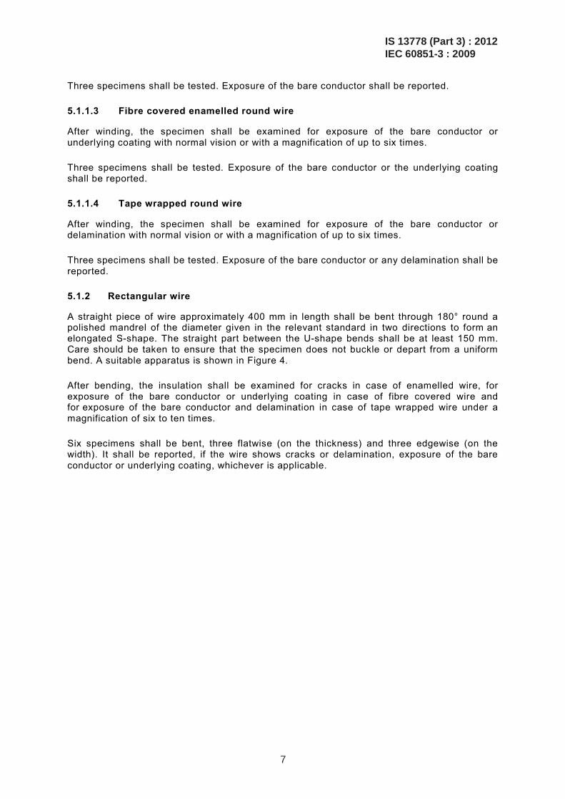
A straight piece of wire approximately 400 mm in length shall be bent through 180° round a polished mandrel of the diameter given in the relevant standard in two directions to form an elongated S-shape. The straight part between the U-shape bends shall be at least 150 mm. Care should be taken to ensure that the specimen does not buckle or depart from a uniform bend. A suitable apparatus is shown in Figure 4.
After bending, the insulation shall be examined for cracks in case of enamelled wire, for exposure of the bare conductor or underlying coating in case of fibre covered wire and for exposure of the bare conductor and delamination in case of tape wrapped wire under a magnification of six to ten times.
Six specimens shall be bent, three flatwise (on the thickness) and three edgewise (on the width). It shall be reported, if the wire shows cracks or delamination, exposure of the bare conductor or underlying coating, whichever is applicable.
IS 13778 (Part 3) : 2012IEC 60851-3 : 2009
7
4
5
6
7
3
1
2
8
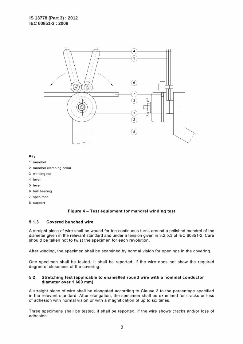
Key
1 mandrel
2 mandrel clamping collar
3 winding nut
4 lever
5 lever
6 ball bearing
7 specimen
8 support
Figure 4 – Test equipment for mandrel winding test
5.1.3 Covered bunched wire
A straight piece of wire shall be wound for ten continuous turns around a polished mandrel of the diameter given in the relevant standard and under a tension given in 3.2.5.3 of IEC 60851-2. Care should be taken not to twist the specimen for each revolution.
After winding, the specimen shall be examined by normal vision for openings in the covering.
One specimen shall be tested. It shall be reported, if the wire does not show the required degree of closeness of the covering.
5.2 Stretching test (applicable to enamelled round wire with a nominal conductor diameter over 1,600 mm)
A straight piece of wire shall be elongated according to Clause 3 to the percentage specified in the relevant standard. After elongation, the specimen shall be examined for cracks or loss of adhesion with normal vision or with a magnification of up to six times.
Three specimens shall be tested. It shall be reported, if the wire shows cracks and/or loss of adhesion.
IS 13778 (Part 3) : 2012IEC 60851-3 : 2009
8
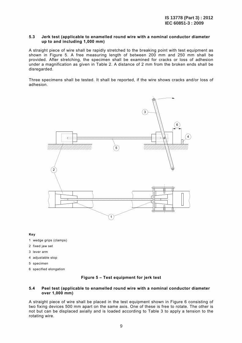
5.3 Jerk test (applicable to enamelled round wire with a nominal conductor diameter up to and including 1,000 mm)
A straight piece of wire shall be rapidly stretched to the breaking point with test equipment as shown in Figure 5. A free measuring length of between 200 mm and 250 mm shall be provided. After stretching, the specimen shall be examined for cracks or loss of adhesion under a magnification as given in Table 2. A distance of 2 mm from the broken ends shall be disregarded.
Three specimens shall be tested. It shall be reported, if the wire shows cracks and/or loss of adhesion.
2
1
5
3
6
4
Key
1 wedge grips (clamps)
2 fixed jaw set
3 lever arm
4 adjustable stop
5 specimen
6 specified elongation
Figure 5 – Test equipment for jerk test
5.4 Peel test (applicable to enamelled round wire with a nominal conductor diameter over 1,000 mm)
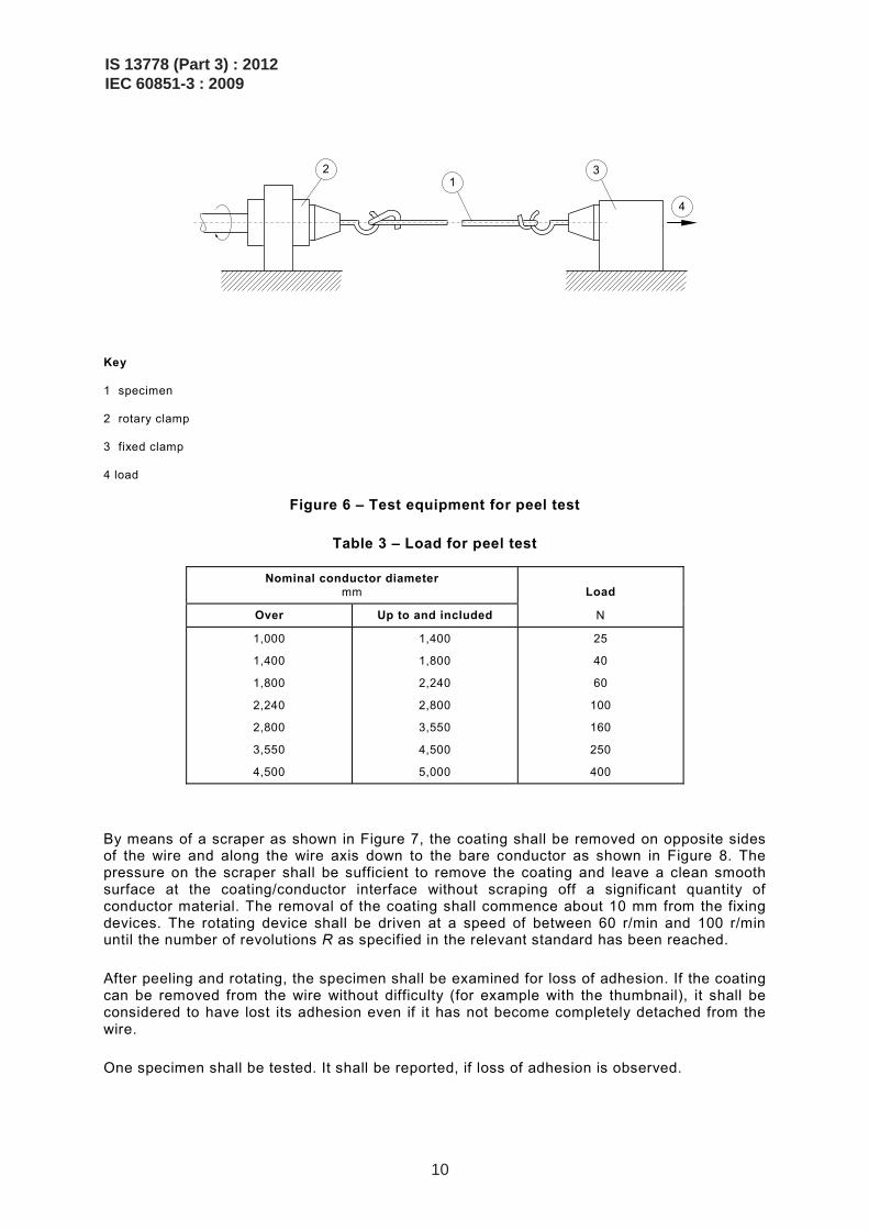
A straight piece of wire shall be placed in the test equipment shown in Figure 6 consisting of two fixing devices 500 mm apart on the same axis. One of these is free to rotate. The other is not but can be displaced axially and is loaded according to Table 3 to apply a tension to the rotating wire.
IS 13778 (Part 3) : 2012IEC 60851-3 : 2009
9
2 1
3
4
Key
1 specimen
2 rotary clamp
3 fixed clamp
4 load
Figure 6 – Test equipment for peel test
Table 3 – Load for peel test
Nominal conductor diameter mm
Load
Over Up to and included N
1,000
1,400
1,800
2,240
2,800
3,550
4,500
1,400
1,800
2,240
2,800
3,550
4,500
5,000
25
40
60
100
160
250
400
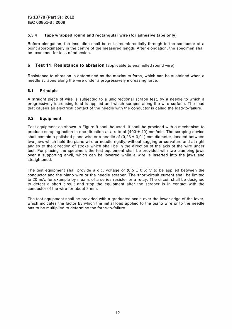
By means of a scraper as shown in Figure 7, the coating shall be removed on opposite sides of the wire and along the wire axis down to the bare conductor as shown in Figure 8. The pressure on the scraper shall be sufficient to remove the coating and leave a clean smooth surface at the coating/conductor interface without scraping off a significant quantity of conductor material. The removal of the coating shall commence about 10 mm from the fixing devices. The rotating device shall be driven at a speed of between 60 r/min and 100 r/min until the number of revolutions R as specified in the relevant standard has been reached.
After peeling and rotating, the specimen shall be examined for loss of adhesion. If the coating can be removed from the wire without difficulty (for example with the thumbnail), it shall be considered to have lost its adhesion even if it has not become completely detached from the wire.
One specimen shall be tested. It shall be reported, if loss of adhesion is observed.
IS 13778 (Part 3) : 2012IEC 60851-3 : 2009
10
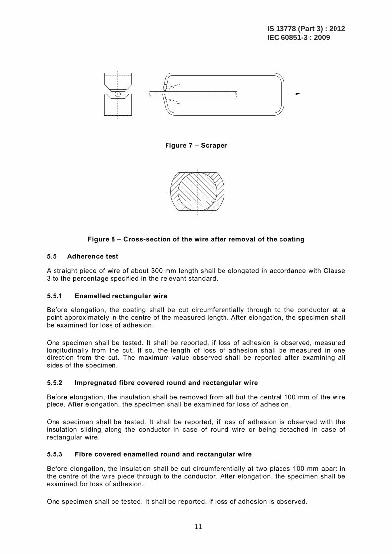
Figure 7 – Scraper
Figure 8 – Cross-section of the wire after removal of the coating
5.5 Adherence test
A straight piece of wire of about 300 mm length shall be elongated in accordance with Clause 3 to the percentage specified in the relevant standard.
5.5.1 Enamelled rectangular wire
Before elongation, the coating shall be cut circumferentially through to the conductor at a point approximately in the centre of the measured length. After elongation, the specimen shall be examined for loss of adhesion.
One specimen shall be tested. It shall be reported, if loss of adhesion is observed, measured longitudinally from the cut. If so, the length of loss of adhesion shall be measured in one direction from the cut. The maximum value observed shall be reported after examining all sides of the specimen.
5.5.2 Impregnated fibre covered round and rectangular wire
Before elongation, the insulation shall be removed from all but the central 100 mm of the wire piece. After elongation, the specimen shall be examined for loss of adhesion.
One specimen shall be tested. It shall be reported, if loss of adhesion is observed with the insulation sliding along the conductor in case of round wire or being detached in case of rectangular wire.
5.5.3 Fibre covered enamelled round and rectangular wire
Before elongation, the insulation shall be cut circumferentially at two places 100 mm apart in the centre of the wire piece through to the conductor. After elongation, the specimen shall be examined for loss of adhesion.
One specimen shall be tested. It shall be reported, if loss of adhesion is observed.
IS 13778 (Part 3) : 2012IEC 60851-3 : 2009
11
5.5.4 Tape wrapped round and rectangular wire (for adhesive tape only)
Before elongation, the insulation shall be cut circumferentially through to the conductor at a point approximately in the centre of the measured length. After elongation, the specimen shall be examined for loss of adhesion.
6 Test 11: Resistance to abrasion (applicable to enamelled round wire)
Resistance to abrasion is determined as the maximum force, which can be sustained when a needle scrapes along the wire under a progressively increasing force.
6.1 Principle
A straight piece of wire is subjected to a unidirectional scrape test, by a needle to which a progressively increasing load is applied and which scrapes along the wire surface. The load that causes an electrical contact of the needle with the conductor is called the load-to-failure.
6.2 Equipment
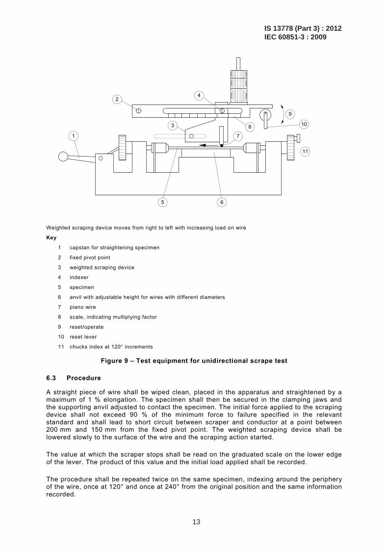
Test equipment as shown in Figure 9 shall be used. It shall be provided with a mechanism to produce scraping action in one direction at a rate of (400 ± 40) mm/min. The scraping device shall contain a polished piano wire or a needle of (0,23 ± 0,01) mm diameter, located between two jaws which hold the piano wire or needle rigidly, without sagging or curvature and at right angles to the direction of stroke which shall be in the direction of the axis of the wire under test. For placing the specimen, the test equipment shall be provided with two clamping jaws over a supporting anvil, which can be lowered while a wire is inserted into the jaws and straightened.
The test equipment shall provide a d.c. voltage of (6,5 ± 0,5) V to be applied between the conductor and the piano wire or the needle scraper. The short-circuit current shall be limited to 20 mA, for example by means of a series resistor or a relay. The circuit shall be designed to detect a short circuit and stop the equipment after the scraper is in contact with the conductor of the wire for about 3 mm.
The test equipment shall be provided with a graduated scale over the lower edge of the lever, which indicates the factor by which the initial load applied to the piano wire or to the needle has to be multiplied to determine the force-to-failure.
IS 13778 (Part 3) : 2012IEC 60851-3 : 2009
12
1
2
3
4
7
8
9
10
11
5 6
Weighted scraping device moves from right to left with increasing load on wire
Key
1 capstan for straightening specimen
2 fixed pivot point
3 weighted scraping device
4 indexer
5 specimen
6 anvil with adjustable height for wires with different diameters
7 piano wire
8 scale, indicating multiplying factor
9 reset/operate
10 reset lever
11 chucks index at 120° increments
Figure 9 – Test equipment for unidirectional scrape test
6.3 Procedure
A straight piece of wire shall be wiped clean, placed in the apparatus and straightened by a maximum of 1 % elongation. The specimen shall then be secured in the clamping jaws and the supporting anvil adjusted to contact the specimen. The initial force applied to the scraping device shall not exceed 90 % of the minimum force to failure specified in the relevant standard and shall lead to short circuit between scraper and conductor at a point between 200 mm and 150 mm from the fixed pivot point. The weighted scraping device shall be lowered slowly to the surface of the wire and the scraping action started.
The value at which the scraper stops shall be read on the graduated scale on the lower edge of the lever. The product of this value and the initial load applied shall be recorded.
The procedure shall be repeated twice on the same specimen, indexing around the periphery of the wire, once at 120° and once at 240° from the original position and the same information recorded.
IS 13778 (Part 3) : 2012IEC 60851-3 : 2009
13
One specimen shall be tested. The three single values shall be reported. The mean value represents the average force-to-failure.
7 Test 18: Heat bonding (applicable to enamelled round wire with a nominal conductor diameter over 0,050 mm up to and including 2 000 mm)
Heat bonding is the potential of the windings of a coil to bond together under the influence of heat.
7.1 Vertical bond retention of a helical coil
Vertical bond retention of a helical coil is the potential of the bonded coil to maintain its coherence when a load is applied to its lower end.
7.1.1 Nominal conductor diameter up to and including 0,050 mm
The method of test is to be agreed upon between purchaser and supplier.
7.1.2 Nominal conductor diameter over 0,050 mm up to and including 2,000 mm
7.1.2.1 Principle
The turns of a helical coil of the wire wound on a mandrel are pressed together by applying a load and then bonded by means of heat or solvent. After bonding, the specimen is removed from the mandrel and suspended in a vertical position with a load applied at the lower end to determine whether the specimen withstands a specified load or not. This procedure is repeated at an elevated temperature.
7.1.2.2 Specimen
A straight piece of wire shall be wound on a polished mandrel1 of a diameter according to Table 4. The coil shall have a minimum length of 20 mm. The winding rate shall be between 1 r/s and 3 r/s with an applied winding force not exceeding the values in Table 4. In order to allow the coil to relax freely, the ends of the wire shall not be fastened. The coil on the mandrel shall be positioned vertically as shown in Figure 10a with a load applied as specified in Table 4. The weight shall not stick to the mandrel, and there shall be a clearance between the weight and the mandrel. This arrangement shall then be placed in an oven with forced air circulation at a temperature specified in the relevant standard for a period of
– 30 min for wires with a nominal conductor diameter up to and including 0,710 mm; – 1 h for wires with a nominal conductor diameter over 0,710 mm up to and including
2,000 mm, unless otherwise agreed upon between purchaser and supplier.
After cooling to room temperature, the coil shall be removed from the mandrel.
7.1.2.3 Procedure at room temperature
A specimen shall be suspended by one of its ends (see Figure 10b) and loaded as required in the relevant standard. The load shall be applied in a way that avoids any additional shock.
Three specimens shall be tested. It shall be reported, if turns other than the first and the last are separated. The temperature for bonding the specimen shall be reported.
————————— 1 A steel mandrel is satisfactory for larger diameter wires. For smaller wires, copper mandrels may assist in the
removal of the coil from the mandrel by stretching the mandrel to reduce its diameter.
IS 13778 (Part 3) : 2012IEC 60851-3 : 2009
14
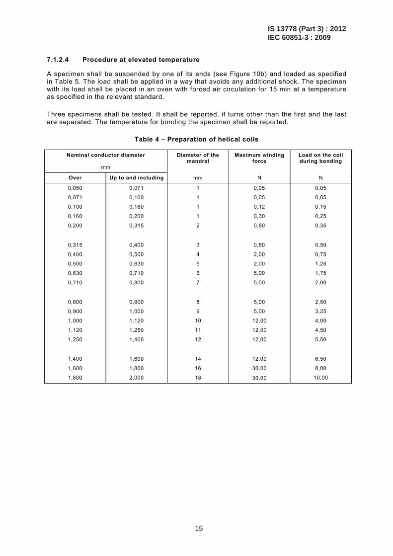
7.1.2.4 Procedure at elevated temperature
A specimen shall be suspended by one of its ends (see Figure 10b) and loaded as specified in Table 5. The load shall be applied in a way that avoids any additional shock. The specimen with its load shall be placed in an oven with forced air circulation for 15 min at a temperature as specified in the relevant standard.
Three specimens shall be tested. It shall be reported, if turns other than the first and the last are separated. The temperature for bonding the specimen shall be reported.
Table 4 – Preparation of helical coils
Nominal conductor diameter
mm
Diameter of the mandrel
Maximum winding force
Load on the coil during bonding
Over Up to and including mm N N
0,050
0,071
0,100
0,160
0,200
0,315
0,400
0,500
0,630
0,710
0,800
0,900
1,000
1,120
1,250
1,400
1,600
1,800
0,071
0,100
0,160
0,200
0,315
0,400
0,500
0,630
0,710
0,800
0,900
1,000
1,120
1,250
1,400
1,600
1,800
2,000
1
1
1
1
2
3
4
5
6
7
8
9
10
11
12
14
16
18
0,05
0,05
0,12
0,30
0,80
0,80
2,00
2,00
5,00
5,00
5,00
5,00
12,00
12,00
12,00
12,00
30,00
30,00
0,05
0,05
0,15
0,25
0,35
0,50
0,75
1,25
1,75
2,00
2,50
3,25
4,00
4,50
5,50
6,50
8,00
10,00
IS 13778 (Part 3) : 2012IEC 60851-3 : 2009
15
2
4
3
5
1
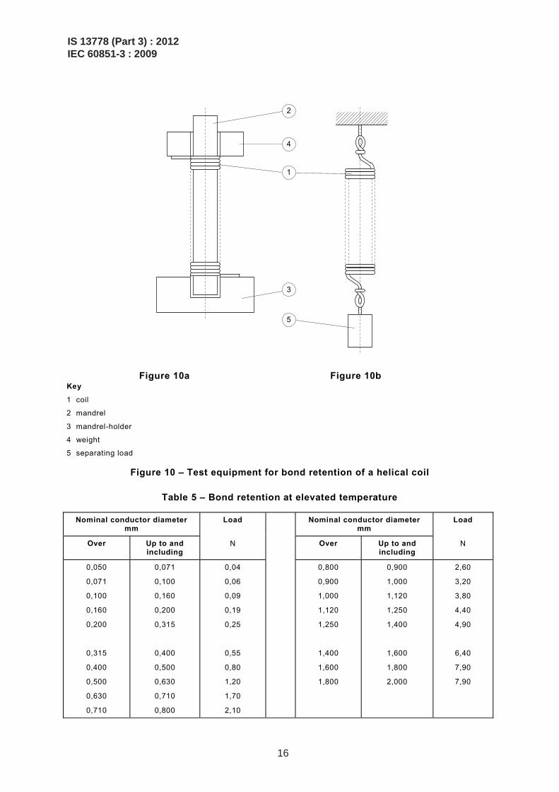
Key
1 coil
2 mandrel
3 mandrel-holder
4 weight
5 separating load
Figure 10 – Test equipment for bond retention of a helical coil
Table 5 – Bond retention at elevated temperature
Nominal conductor diameter mm
Load Nominal conductor diameter mm
Load
Over Up to and including
N Over Up to and including
N
0,050
0,071
0,100
0,160
0,200
0,315
0,400
0,500
0,630
0,710
0,071
0,100
0,160
0,200
0,315
0,400
0,500
0,630
0,710
0,800
0,04
0,06
0,09
0,19
0,25
0,55
0,80
1,20
1,70
2,10
0,800
0,900
1,000
1,120
1,250
1,400
1,600
1,800
0,900
1,000
1,120
1,250
1,400
1,600
1,800
2,000
2,60
3,20
3,80
4,40
4,90
6,40
7,90
7,90
Figure 10a Figure 10b
IS 13778 (Part 3) : 2012IEC 60851-3 : 2009
16
7.2 Bond strength of a twisted coil
Bond strength is the maximum force required to break the twisted coil.
7.2.1 Principle
A random wound coil prepared from the wire is formed to an oval shape, twisted and then bonded by applying a d.c. current. This specimen produces a rod, which is tested in tensile testing equipment in a horizontal position to obtain the maximum deflection force to break this rod. The test shall be repeated at elevated temperature.
NOTE This test is similar to method A, twisted coil test, given in 2.1 of IEC 61033, and is based on the same principle. It differs from method A of IEC 61033 with respect to twisting and bonding the specimen and with respect to wire sizes. It permits the testing of different wire sizes, whereas method A of IEC 61033 specifies that a wire of a nominal conductor diameter of 0,315 mm shall be used.
7.2.2 Equipment
The following equipment shall be used:
– coil winder in accordance with Figures 11a and 11b; – coil twister in accordance with Figure 13; – tensile test equipment in accordance with ISO 178 with a support complying with Figure
13; – d.c. supply unit providing a constant current output with a capacity of minimum 50 V and
15 A; – attached to the tensile test equipment, an oven with forced air circulation, which shall
maintain the test temperature within a tolerance of ±2 °C and which shall allow heating at least five specimens simultaneously within 5 min to 10 min to the test temperature.
7.2.3 Specimen
A random wound coil shall be prepared from the wire using winding equipment according to Figures 11a and 11b. The number of windings shall be calculated as
2
20,315100
dN ×=
where d is the nominal conductor diameter of the wire under test.
NOTE For a nominal conductor diameter of d = 0,315 mm, N represents 100 turns. For other values of d, the above equation will lead to a number N, which gives the same total conductor cross-section as N = 100 and d = 0,315 mm.
To prevent opening of the coil after removal from the winding equipment, each end of the wire (or short pieces of enamelled wire) shall be wrapped around the coil two or three times at opposite positions. For this purpose, the winding equipment is provided with appropriate notches (see Figure 11b).
For winding the coil, the following dimensions shall apply:
– winding diameter: (57 ± 0,1) mm;
– width of slot: (5 ± 0,5) mm.
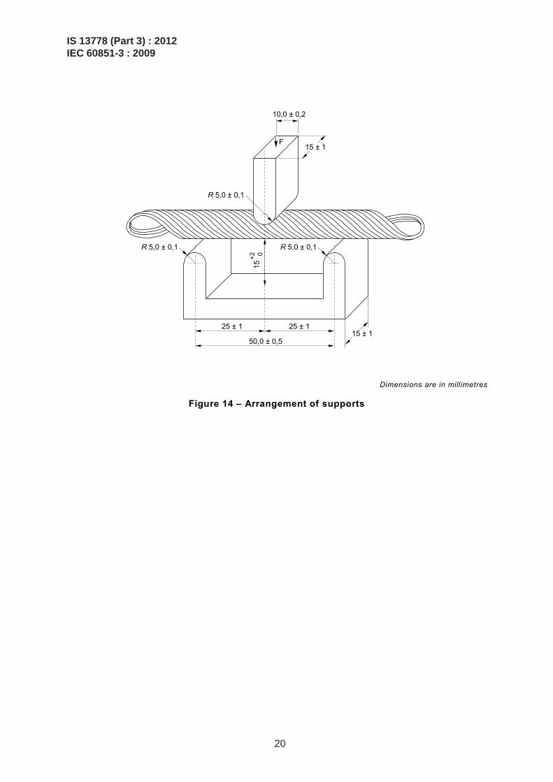
After removal from the winding equipment, the coil shall be formed to an oval shape (see Figure 12) and then twisted in a twisting device around its longitudinal axis according to Figure 13. This device allows application of a mechanical load to be applied to the coil while it is twisted and subsequently bonded. This load shall be 100 N. The coil shall be twisted for
IS 13778 (Part 3) : 2012IEC 60851-3 : 2009
17
two and a half turns and then half a turn in the reverse direction. While held under a mechanical load in the twisting device, the specimen shall be bonded by applying a constant d.c. current to the wire. A current shall be chosen that bonds the specimen within a period of 30 s to 60 s.
NOTE Since d.c. current is used, it allows an easy approach to determine the average temperature of the specimen at the end of the heating period (see Annex A).
The specimen is a rod of about 7 mm in diameter and 85 mm to 90 mm in length.
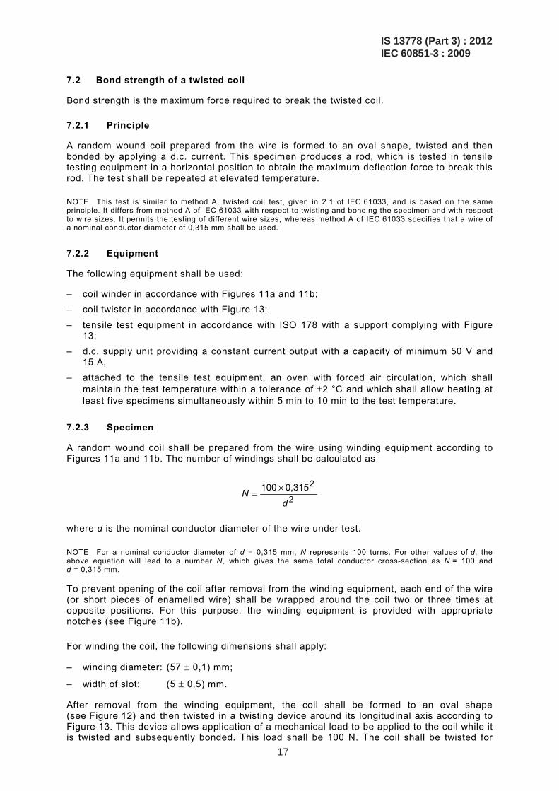
5 mm ± 0,5 mm
Figure 11a – Coil winder
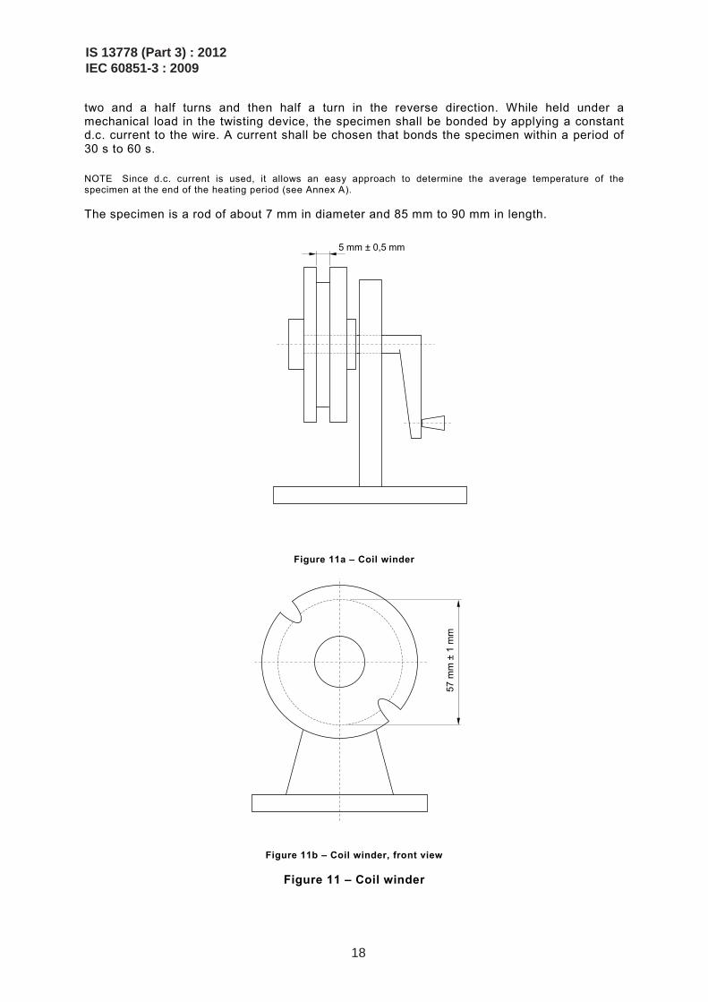
57 m
m ±
1 m
m
Figure 11b – Coil winder, front view
Figure 11 – Coil winder
IS 13778 (Part 3) : 2012IEC 60851-3 : 2009
18
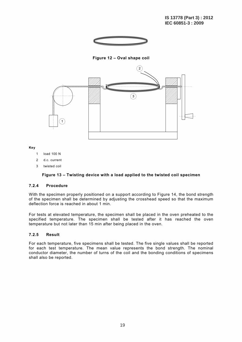
Figure 12 – Oval shape coil
1
3
2
Key
1 load 100 N
2 d.c. current
3 twisted coil
Figure 13 – Twisting device with a load applied to the twisted coil specimen
7.2.4 Procedure
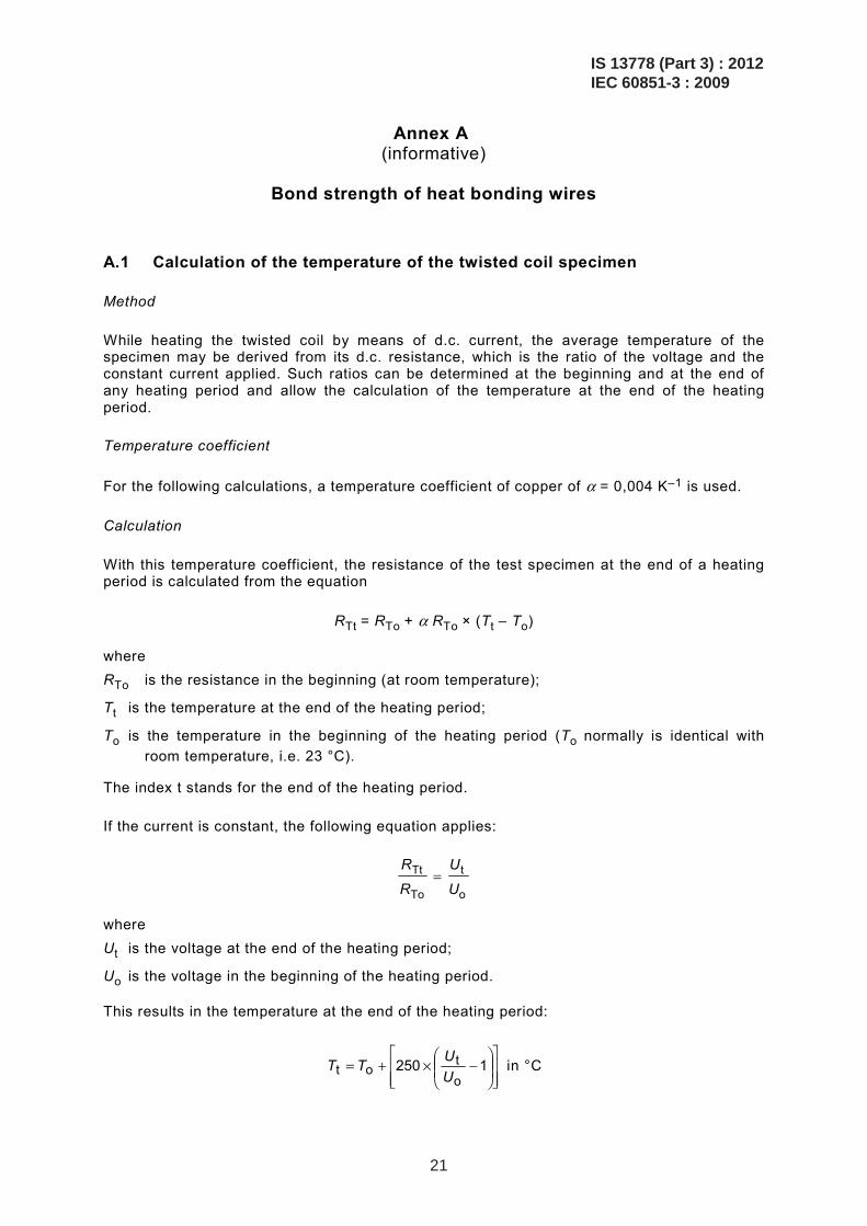
With the specimen properly positioned on a support according to Figure 14, the bond strength of the specimen shall be determined by adjusting the crosshead speed so that the maximum deflection force is reached in about 1 min.
For tests at elevated temperature, the specimen shall be placed in the oven preheated to the specified temperature. The specimen shall be tested after it has reached the oven temperature but not later than 15 min after being placed in the oven.
7.2.5 Result
For each temperature, five specimens shall be tested. The five single values shall be reported for each test temperature. The mean value represents the bond strength. The nominal conductor diameter, the number of turns of the coil and the bonding conditions of specimens shall also be reported.
IS 13778 (Part 3) : 2012IEC 60851-3 : 2009
19
10,0 ± 0,2
15 ± 1
25 ± 1 25 ± 1
50,0 ± 0,5
R 5,0 ± 0,1
R 5,0 ± 0,1 R 5,0 ± 0,1
15 ± 1
15 +2
0
F
Dimensions are in millimetres
Figure 14 – Arrangement of supports
IS 13778 (Part 3) : 2012IEC 60851-3 : 2009
20
Annex A (informative)
Bond strength of heat bonding wires
A.1 Calculation of the temperature of the twisted coil specimen
Method
While heating the twisted coil by means of d.c. current, the average temperature of the specimen may be derived from its d.c. resistance, which is the ratio of the voltage and the constant current applied. Such ratios can be determined at the beginning and at the end of any heating period and allow the calculation of the temperature at the end of the heating period.
Temperature coefficient
For the following calculations, a temperature coefficient of copper of α = 0,004 K–1 is used.
Calculation
With this temperature coefficient, the resistance of the test specimen at the end of a heating period is calculated from the equation
RTt = RTo + α RTo × (Tt – To)
where RTo is the resistance in the beginning (at room temperature);
Tt is the temperature at the end of the heating period;
To is the temperature in the beginning of the heating period (To normally is identical with room temperature, i.e. 23 °C).
The index t stands for the end of the heating period.
If the current is constant, the following equation applies:
R
R
U
UTt
To
t
o=
where Ut is the voltage at the end of the heating period;
Uo is the voltage in the beginning of the heating period.
This results in the temperature at the end of the heating period:
⎥⎥⎦
⎤
⎢⎢⎣
⎡⎟⎟⎠
⎞⎜⎜⎝
⎛−×+= 1250
ot
ot UUTT in °C
IS 13778 (Part 3) : 2012IEC 60851-3 : 2009
21
A.2 Determination of the heating period
Voltage-time graphs
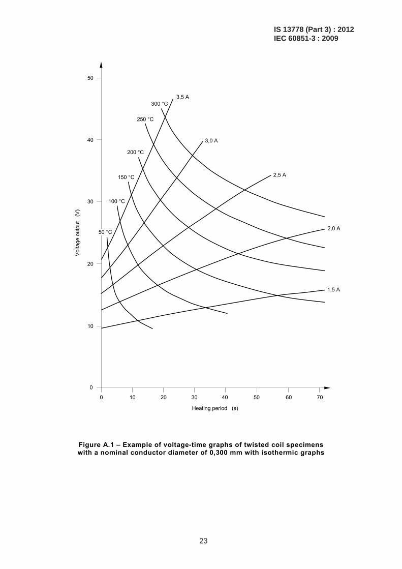
While heating the twisted coil with a constant current, the electrical resistance increases with the temperature. To maintain the current, the voltage output of the constant current transformer increases accordingly. This allows plotting of d.c. voltage output against time. This provides information about the time t of the heating period. Different graphs may be taken for different currents all plotted on one and the same diagram.
Voltage at maximum temperature
In a specific case one may wish to bond the specimen up to a certain temperature, but not to exceed this temperature. If this maximum temperature is defined, the last equation as shown in A.1 allows the calculation of the voltage required to reach that temperature with a particular heating current:
Ut = Uo + 0,004 × (Tt – To) Uo
The point of intersection of the voltage-time graph with the Y-axis corresponds to the value of Uo. With this reading, the last equation allows the calculation of the voltage to arrive at the temperature of the specimen at the end of the heating period. The corresponding value of the X-axis gives the time length of the heating period required to reach the temperature Tt.
If the same calculation is done with all voltage-time graphs for one and the same temperature Tt, the corresponding entries may be used to produce an isothermic graph that intersects the voltage-time graphs. If this is repeated with different temperatures, it results in a final diagram, which is very helpful in selecting a suitable pair of values for the heating current in amperes and the time in seconds of the heating period to heat the test specimen up to the chosen temperature Tt.
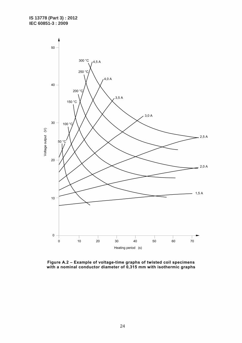
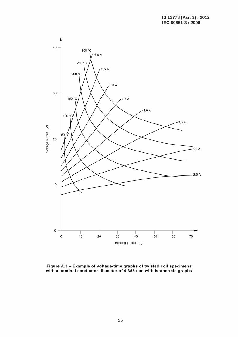
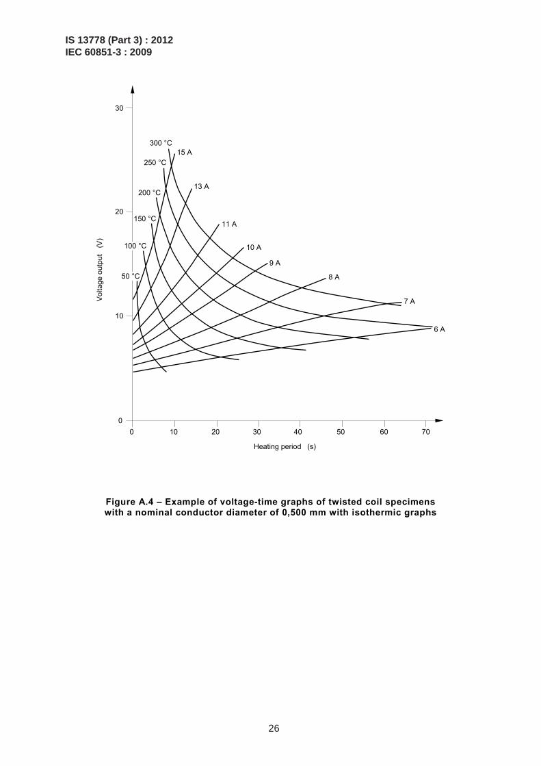
Figures A.1 through A.4 show examples of such complete diagrams for easy reference, based on wire sizes 0,300 mm, 0,315 mm, 0,355 mm and 0,500 mm respectively.
IS 13778 (Part 3) : 2012IEC 60851-3 : 2009
22
50
40
30
20
10
0
0 10 20 30 40 50 60 70
Heating period (s)
Vol
tage
out
put
(V)
300 °C
250 °C
200 °C
150 °C
100 °C
50 °C
3,5 A
3,0 A
2,5 A
2,0 A
1,5 A
Figure A.1 – Example of voltage-time graphs of twisted coil specimens with a nominal conductor diameter of 0,300 mm with isothermic graphs
IS 13778 (Part 3) : 2012IEC 60851-3 : 2009
23
50
40
30
20
10
0
0 10 20 30 40 50 60 70
Heating period (s)
Vol
tage
out
put
(V)
300 °C
250 °C
200 °C
150 °C
100 °C
50 °C
4,5 A
3,5 A
2,5 A
2,0 A
4,0 A
3,0 A
1,5 A
Figure A.2 – Example of voltage-time graphs of twisted coil specimens with a nominal conductor diameter of 0,315 mm with isothermic graphs
IS 13778 (Part 3) : 2012IEC 60851-3 : 2009
24
40
30
20
10
0
0 10 20 30 40 50 60 70
Heating period (s)
Vol
tage
out
put
(V)
300 °C
250 °C
200 °C
150 °C
100 °C
50 °C
6,0 A
5,0 A
3,5 A
3,0 A
2,5 A
5,5 A
4,5 A
4,0 A
Figure A.3 – Example of voltage-time graphs of twisted coil specimens with a nominal conductor diameter of 0,355 mm with isothermic graphs
IS 13778 (Part 3) : 2012IEC 60851-3 : 2009
25
30
20
10
0 0 10 20 30 40 50 60 70
Heating period (s)
Vol
tage
out
put
(V)
300 °C
250 °C
200 °C
150 °C
100 °C
50 °C
15 A
7 A
13 A
11 A
10 A
9 A
8 A
6 A
Figure A.4 – Example of voltage-time graphs of twisted coil specimens with a nominal conductor diameter of 0,500 mm with isothermic graphs
IS 13778 (Part 3) : 2012IEC 60851-3 : 2009
26
Annex B (informative)
Friction test methods
B.1 General
This annex provides recommendations to the purchaser and supplier of winding wires with respect to friction test methods to be used for winding wires.
B.2 Test A: Static coefficient of friction test method
B.2.1 Method of test (applicable to enamelled round wires with a nominal conductor diameter from 0,050 mm up to and including 1,600 mm).
The static coefficient of friction (µs) is determined by measuring the inclining angle (α) of a plane at the moment when a block begins to slip on the track made from the wire specimen. The wire test specimen shall be removed from the delivery spools by de-reeling over the end flange. The top layers of the spool shall be removed before testing when the wire surface is contaminated by dirt or dust. One part of the wire specimen is straightened and then fixed on the inclining plane by means of the two posts and the two clamps constituting the sliding track. The other part of the wire specimen is mounted in a similar way on the sliding block.
The sliding block with the wire specimen is then placed on the track of the plane to be inclined in such a way that the wire on the block and the wire on the plane are crossed at right angles at the point of contact.
The plane is then slowly inclined (approximately 1°/s) until the block starts to slide down the track. At that moment, the angle of inclination (α) is read from the scale.
The static coefficient of friction is calculated as follows:
µs = tan α
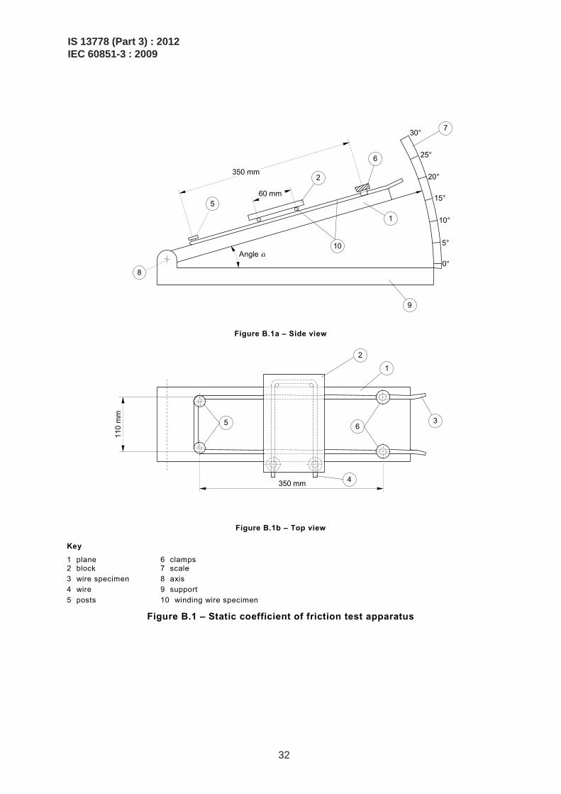
B.2.2 Test apparatus
The general arrangement of the test apparatus is shown in Figure B.1.
The apparatus consists of a plane (1), which can be inclined to an angle (α) by turning the plane around the axis (8). The support (9) carries a scale (7) marked with the inclination angle (α) or the coefficient of friction (tan α).
The plane has means for fixing the wire specimen (3), for example the two posts (5) and the two clamps (6). The parallel parts of the wire shall be 110 mm apart. They form a sliding track running from the scale end to the axis on the plane.
On the block (2) clamps and posts are provided to fix the second wire specimen (4). The parallel parts of the specimen shall be 60 mm apart. The size of the block must allow the clamps and posts to stay clear of the plane (1) to avoid additional friction forces. The block shall have
IS 13778 (Part 3) : 2012IEC 60851-3 : 2009
27
– a mass of about 50 g for a wire with a nominal conductor diameter up to and inclu-ding 0,150 mm;
– a mass of about 500 g for a wire with a nominal conductor diameter over 0,150 mm.
The mass is not critical as it is anyway changed by the mass of the second wire specimen.
The angle of inclination shall be changed slowly by means of a motor-operated block and tackle.
B.3 Test B: First dynamic coefficient of friction test method
B.3.1 Principle
The coefficient of friction, µd, is determined by measuring the frictional force, C, applied on the wire when moving under the pressure of a known mass, E:
E,C
×=
819dμ
B.3.2 Method of test
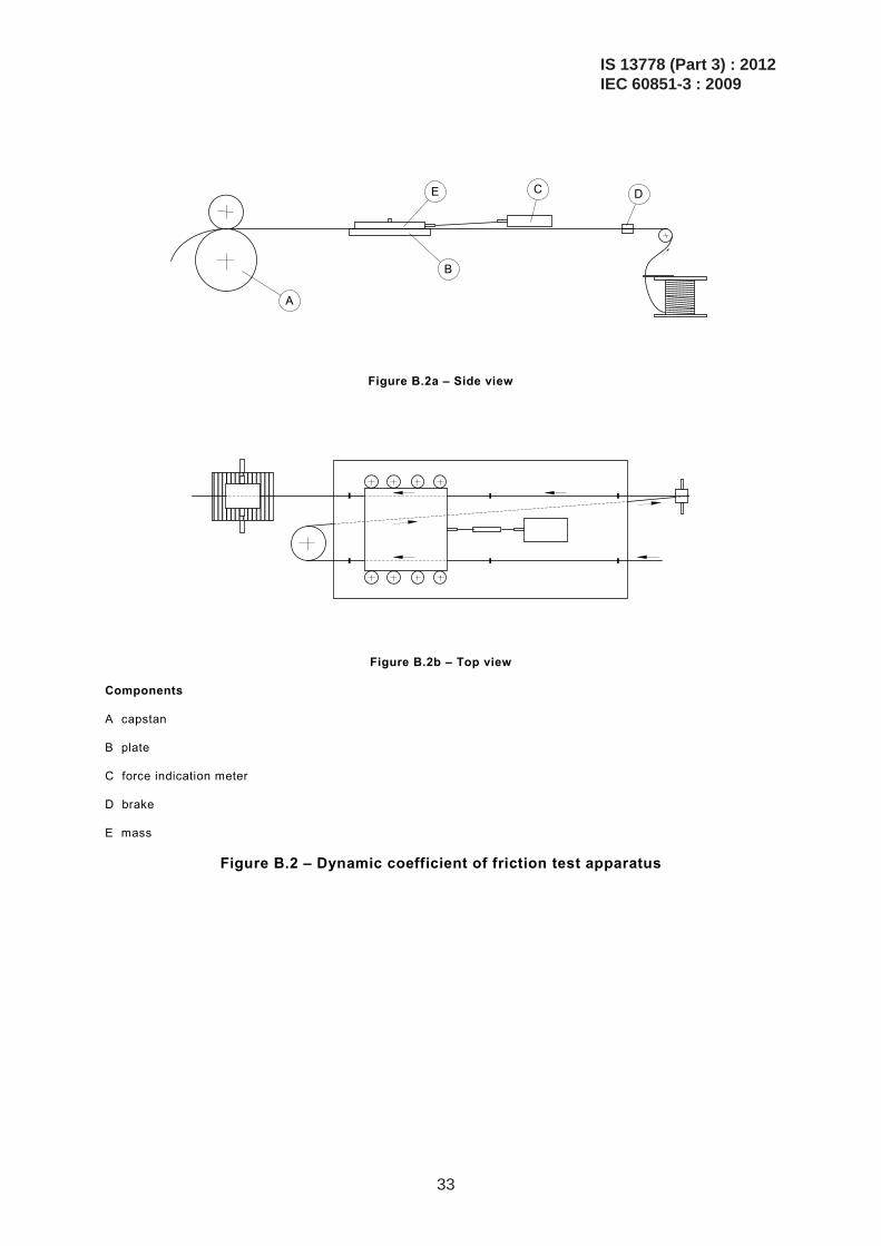
The general arrangement of the test apparatus is shown in Figure B.2.
The enamelled wire runs via a guide wheel and a brake (D) over a metal plate (B). Via another guide wheel, the wire is lead below this plate (B) and runs back, parallel with the first passage, over this plate again (see Figure B.2). By means of a capstan (A), the wire is drawn with a speed of 0,25 m/s. A mass (E) is placed on the running wire over the plate (B), which is coupled to a force indication meter (C).
The force indication meter can be coupled to a linear recorder (measuring range 1 mV - 250 mV). This linear recorder shows the spread of the smoothness and the level of the wire smoothness over a long distance.
B.4 Test C: Second dynamic coefficient of friction test method
B.4.1 Method of test (applicable to enamelled round wires with a nominal conductor diameter from 0,050 mm up to and including 1,600 mm)
The wire specimen is pulled under a test load. The force is developed between the wire surface and the load contact surface and transferred to an appropriate measuring device. The reading in Newtons is divided by the load in Newtons for determination of the dynamic coefficient of friction (µd).
The wire test specimen shall be removed from the delivery spools by de-reeling over the end flange or from the pail or drum. The top wire specimen layer of the spool shall be removed before testing if the wire specimen has been contaminated by dirt or dust.
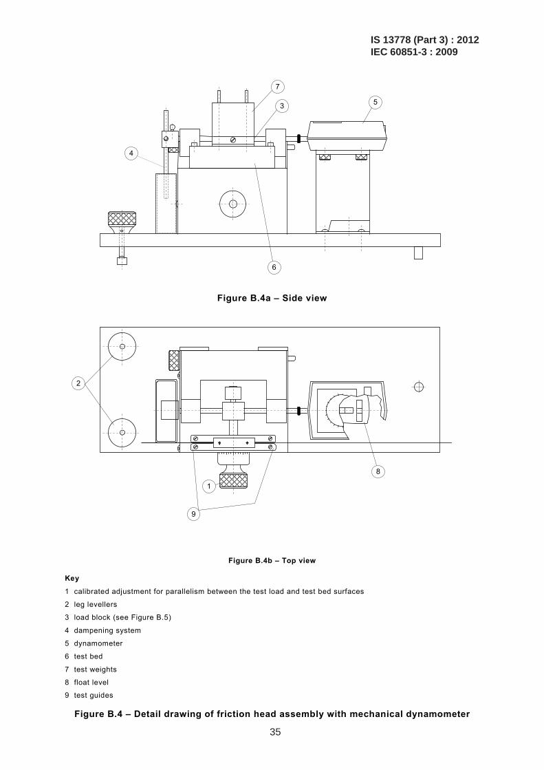
Referring to Figure B.4, level the smooth surface (6) using the levelling leg screws (2) and float level (8).
Adjust the electronic force transducer (5) (Figure B.4) sensitivity to the appropriate range, and set chart recorder to full-scale setting for the wire size being tested using a calibrating weight (9) (Figure B.3). The calibrating weight should be removed after the transducer and chart recorder are adjusted.
IS 13778 (Part 3) : 2012IEC 60851-3 : 2009
28
If a mechanical dynamometer (5) (Figure B.4) is used, adjust the correct range for the wire size being tested.
– Nominal conductor diameters from 0,050 mm up to and including 0,125 mm: 0 N – 0,49 N. – Nominal conductor diameters over 0,125 mm up to and including 1,600 mm: 0 N – 1,96 N.
Clean the sapphire surfaces located on the load block (3) (Figure B.4) in contact with the wire with an appropriate cleaning solvent and allow time to dry thoroughly.
Lower the dampening paddle (4) (Figure B.4) into the oil.
– Completely immerse for sizes over 0,224 mm up to and including 1,600 mm. – Immerse one-half paddle for sizes from 0,050 mm up to and including 0,224 mm.
Thread the wire over appropriate guide pulleys (Figures B.3 (4) and B.4 (9)) so that the wire is in contact with the two sapphires.
Apply the appropriate test load (7) (Figure B.4):
– for sizes over 0,050 mm up to and including 0,071 mm: 0,98 N; – for sizes over 0,071 mm up to and including 0,125 mm: 1,96 N; – for sizes over 0,125 mm up to and including 0,450 mm: 5,88 N; – for sizes over 0,450 mm up to and including 1,600 mm: 9,87 N.
The test load (7) (Figure B.4) should be positioned on the test bed (6) (Figure B.4) where no reading is indicated on the force transducer or dynamometer. If the mechanical dynamometer is used, it should be zeroed.
Adjust the calibrated dial (1) (Figure B.4) to make the test load parallel with the test bed surface. Turn tester on and start the test wire moving.
Slight tension (1) (Figure B.3) should be applied to keep the wire travelling smoothly.
To allow time for the start-up variations to cease, the average dynamometer reading to the nearest Newton should be recorded at least 15 s after start-up.
Calculate the average coefficient of friction (µd) as follows:
μd =F
L
where F is the average dynamometer force reading, in Newtons; L is the test load, in Newtons.
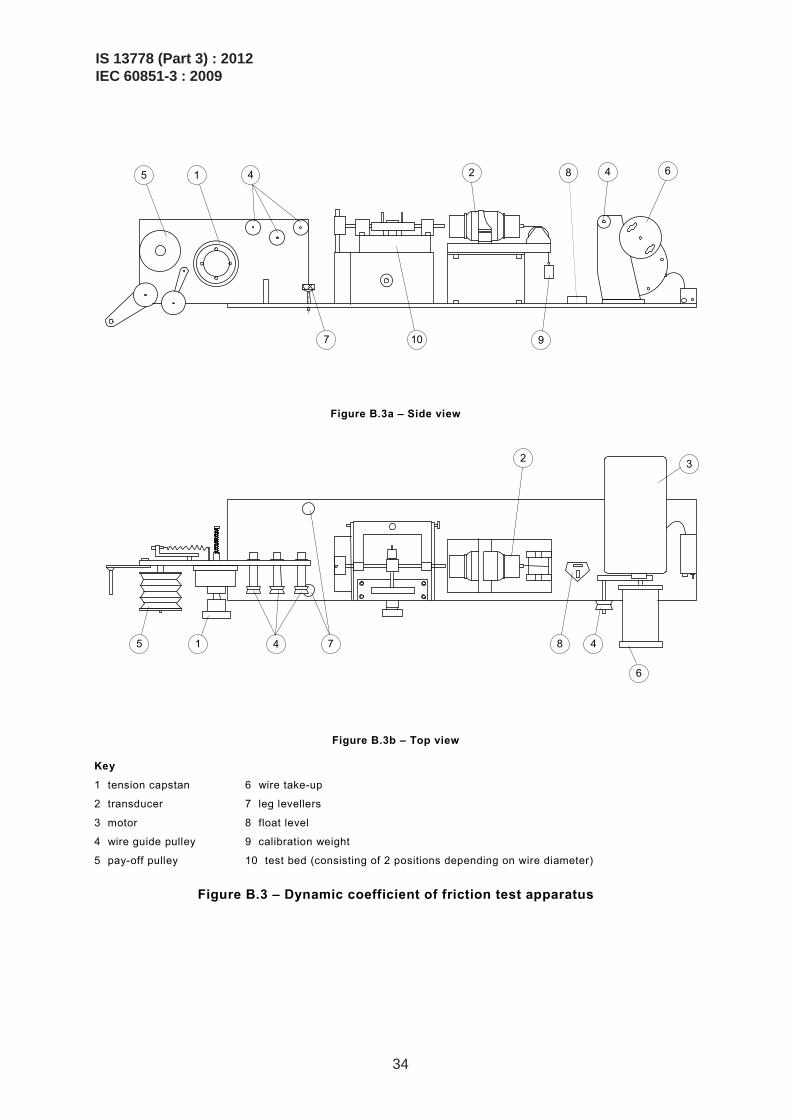
B.4.2 Test apparatus
The general arrangement of the test apparatus is shown in Figures B.3, B.4 and B.5.
A motor (3) (Figure B.3) shall pull the wire specimen at 15 m/min across a smooth surface (10) (Figure B.3) using a motor take-up (6) (Figure B.3).
IS 13778 (Part 3) : 2012IEC 60851-3 : 2009
29
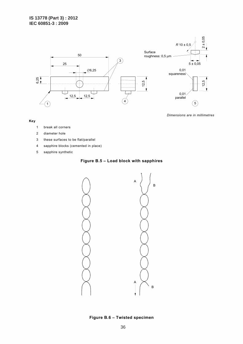
Various load weights (7) (Figure B.4) should be available which will provide 0,98 N – 9,81 N force. The load surface shall be synthetic sapphire and have a surface roughness of not more than 0,5 μm. The sapphires are described and shall be mounted as shown in Figure B.5.
There shall be a means to guide the wire (Figure B.3 (4) and Figure B.4 (9)) and a means to maintain a slight tension (Figure B.3, (1) (5)) if needed.
B.4.3 Measuring device
The measuring device consists of
– electronic force measuring devices or transducers (2) (Figure B.3) incorporated with a chart recorder for measuring the force due to friction. The electronic force measuring device will provide a record indicating the peak variation along the surface of the wire. A force transducer with a range of 0 N – 4,9 N, and a chart recorder with a 0 V – 5 V range and a 0,5 s full-scale response time are satisfactory;
– Figure B.4 illustrates the use of a mechanical dynamometer (5) in place of an electronic force transducer and chart recorder. Two dynamometer ranges, 0 N – 0,49 N and 0 N – 1,96 N, are satisfactory;
– a dampening system (4) (Figure B.4) consisting of a paddle and a container filled to a depth of 5 mm with oil, having a viscosity of approximately 10 200 mPa × s at 25 °C;
– an appropriate cleaning solvent for the lubricant being tested.
B.5 Test D: Force of friction by the twisted pair method
B.5.1 Enamelled round wires with a nominal conductor diameter from 0,1 mm up to and including 1,500 mm
From an enamelled wire specimen a twist is made similar to the one used for test 13 (breakdown voltage) in 4.3 of IEC 60851-5. The end of the first twist strand is attached to a fixed jaw and a force is applied to the opposite end of the second strand that has been kept free to slide by traction and without rotating, using for example a dynamometer. The force to separate the two strands is the sliding force.
B.5.2 Method of test
A specimen approximately of 400 mm in length shall be twisted back on itself for a distance of 125 mm on an apparatus as shown in Figure B.6. The force (weight) applied to the wire pair while being twisted and the number of twists are given in Table B.1.
At the twisted end, the loop is cut in two separate places to obtain a maximum separation between these cut ends.
Any bending of the wires, at the cut end or at the other untwisted end, to ensure adequate separation between the wires, shall avoid sharp bends or damage to the insulation.
One end of one wire shall be attached firmly to a jaw, while at the opposite end of the other wire a force (weight) is applied to let that wire slide without any rotation. Three specimens shall be tested.
IS 13778 (Part 3) : 2012IEC 60851-3 : 2009
30
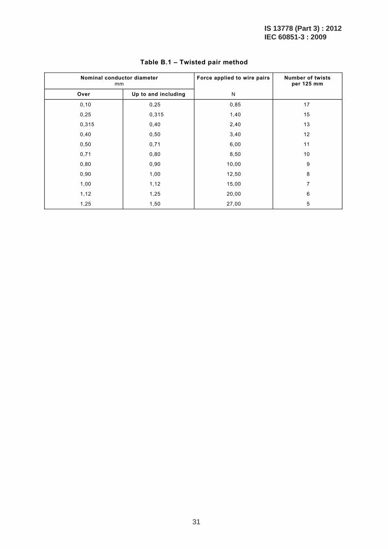
Table B.1 – Twisted pair method
Nominal conductor diameter mm
Force applied to wire pairs Number of twists per 125 mm
Over Up to and including N
0,10
0,25
0,315
0,40
0,50
0,71
0,80
0,90
1,00
1,12
1,25
0,25
0,315
0,40
0,50
0,71
0,80
0,90
1,00
1,12
1,25
1,50
0,85
1,40
2,40
3,40
6,00
8,50
10,00
12,50
15,00
20,00
27,00
17
15
13
12
11
10
9
8
7
6
5
IS 13778 (Part 3) : 2012IEC 60851-3 : 2009
31
350 mm
5
8
2
6
7
10
9
1
60 mm
Angle α
30°
25°
20°
15°
10°
5°
0°
Figure B.1a – Side view
5
2
1
3 6
4
110
mm
350 mm
Figure B.1b – Top view
Key
1 plane 6 clamps 2 block 7 scale 3 wire specimen 8 axis 4 wire 9 support 5 posts 10 winding wire specimen
Figure B.1 – Static coefficient of friction test apparatus
IS 13778 (Part 3) : 2012IEC 60851-3 : 2009
32
A
B
E C D
Figure B.2a – Side view
Figure B.2b – Top view
Components
A capstan
B plate
C force indication meter
D brake
E mass
Figure B.2 – Dynamic coefficient of friction test apparatus
IS 13778 (Part 3) : 2012IEC 60851-3 : 2009
33
5 1 4 2 8 4 6
9 107
Figure B.3a – Side view
5 1 4 7 8 4
6
2 3
Figure B.3b – Top view
Key
1 tension capstan 6 wire take-up
2 transducer 7 leg levellers
3 motor 8 float level
4 wire guide pulley 9 calibration weight
5 pay-off pulley 10 test bed (consisting of 2 positions depending on wire diameter)
Figure B.3 – Dynamic coefficient of friction test apparatus
IS 13778 (Part 3) : 2012IEC 60851-3 : 2009
34
4
6
5 3
7
Figure B.4a – Side view
2
9
1
8
Figure B.4b – Top view
Key
1 calibrated adjustment for parallelism between the test load and test bed surfaces
2 leg levellers
3 load block (see Figure B.5)
4 dampening system
5 dynamometer
6 test bed
7 test weights
8 float level
9 test guides
Figure B.4 – Detail drawing of friction head assembly with mechanical dynamometer
IS 13778 (Part 3) : 2012IEC 60851-3 : 2009
35
3
50
25
6,25
∅6,25
12,5 12,5
12,5
12,5
2
± 0,
05
5 ± 0,05
R 10 ± 0,5
Surface roughness: 0,5 μm
0,01 squareness
0,01 parallel
1 4 5
Dimensions are in millimetres
Key
1 break all corners
2 diameter hole
3 these surfaces to be flat/parallel
4 sapphire blocks (cemented in place)
5 sapphire synthetic
Figure B.5 – Load block with sapphires
AB
AB
Figure B.6 – Twisted specimen
IS 13778 (Part 3) : 2012IEC 60851-3 : 2009
36
Bibliography
IEC 60851-5:2008, Winding wires – Test methods – Part 5: Electrical properties
IEC 61033:1991, Test methods for the determination of bond strength of impregnating agents to an enamelled wire substrate Amendment 1:2006
___________
IS 13778 (Part 3) : 2012IEC 60851-3 : 2009
37

Bureau of Indian Standards
BIS is a statutory institution established under the Bureau of Indian Standards Act, 1986 to promoteharmonious development of the activities of standardization, marking and quality certification of goodsand attending to connected matters in the country.
Copyright
BIS has the copyright of all its publications. No part of these publications may be reproduced in any formwithout the prior permission in writing of BIS. This does not preclude the free use, in course of imple-menting the standard, of necessary details, such as symbols and sizes, type or grade designations.Enquiries relating to copyright be addressed to the Director (Publications), BIS.
Review of Indian Standards
Amendments are issued to standards as the need arises on the basis of comments. Standards are alsoreviewed periodically; a standard along with amendments is reaffirmed when such review indicates thatno changes are needed; if the review indicates that changes are needed, it is taken up for revision. Usersof Indian Standards should ascertain that they are in possession of the latest amendments or edition byreferring to the latest issue of ‘BIS Catalogue’ and ‘Standards: Monthly Additions’.
This Indian Standard has been developed from Doc No.: ETD 33 (6248).
Amendments Issued Since Publication______________________________________________________________________________________
Amendment No. Date of Issue Text Affected______________________________________________________________________________________
______________________________________________________________________________________
______________________________________________________________________________________
______________________________________________________________________________________
______________________________________________________________________________________
BUREAU OF INDIAN STANDARDSHeadquarters:
Manak Bhavan, 9 Bahadur Shah Zafar Marg, New Delhi 110002Telephones: 2323 0131, 2323 3375, 2323 9402 Website: www.bis.org.in
Regional Offices: Telephones
Central : Manak Bhavan, 9 Bahadur Shah Zafar Marg 2323 7617NEW DELHI 110002 2323 3841
Eastern : 1/14, C.I.T. Scheme VII M, V.I.P. Road, Kankurgachi 2337 8499, 2337 8561KOLKATA 700054 2337 8626, 2337 9120
Northern : SCO 335-336, Sector 34-A, CHANDIGARH 160022 260 3843260 9285
Southern : C.I.T. Campus, IV Cross Road, CHENNAI 600113 2254 1216, 2254 14422254 2519, 2254 2315
Western : Manakalaya, E9 MIDC, Marol, Andheri (East) 2832 9295, 2832 7858MUMBAI 400093 2832 7891, 2832 7892
Branches: AHMEDABAD. BANGALORE. BHOPAL. BHUBANESHWAR. COIMBATORE. DEHRADUN.FARIDABAD. GHAZIABAD. GUWAHATI. HYDERABAD. JAIPUR. KANPUR. LUCKNOW.NAGPUR. PARWANOO. PATNA. PUNE. RAJKOT. THIRUVANATHAPURAM. VISAKHAPATNAM.
Published by BIS, New Delhi
{{
{{{