Embed Size (px)
DESCRIPTION
Indian StandardIS:1343-1980( ReaffIrmed 1999 )CODE OF PRACTICE FORPRESTRESSED CONCRETE(First &vision) .
Citation preview
Indian Standard
IS:1343-1980 ( ReaffIrmed 1999 )
CODE OF PRACTICE FOR PRESTRESSED CONCRETE
(First &vision) .
Tenth Reprint MAY 1999
UDC 624.012.46 : 006.76
0 Copyright 198 1
? BUREAU OF INDIAN STANDARDS MANAK BHAVAN, 9 BAI-iADUR SHAH ZAFAR MARG
NEW DELHI 110002
Grll Noventber 198 1
IS : 1343 - 1980
hdian Standard CODE OF PRACTICE FOR PRESTRESSED CONCRETE
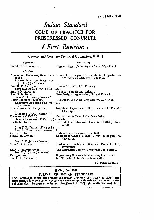
( First Revision ) Cement and Concrete Sectional Committee, BDC 2
Chairman
Dn H. C. VBVESVARAYA
Members
Representing
Cement Research Institute of India, New Delhi
ADDITIONAL DIRECTOR, STANDARDS Research,. Designs & Standards Organization (B&S) ( Mmlstry of Railways j, Lucknow
DEPUTY DIRECTOR, STANDARDS ( B & S ) ( Alternate )
SHRI K. P. BANERJEE Larsrn & Toubro Ltd, Bombay SHRI HARISH N. MALANI ( Alternate j
SHRT S. K. BANERJEE National Test House, Calcutta SHRI R. N. BANSAL
SHRI T. C. GAkc ( Afternafc j Beas Designs Organization, Nangal Township
CHIEF ENGINEER ( DESIGNS) Central Public \\‘orks Department, New Delhi EXECUTIVE ENGINEER ( DESIQNS) III
( Alternate j CHIEF ENQINEER ( PaoJEo’rs j Irrigation Department, Government of Pur jab,
DIRECTOR, IPRI ( Alternate j Chandigarh
DIRECTOR ( CSMRS) Central Water Commission, New Delhi DEPU~ DIRECTOR ( CSMRS j ( Alternate )
DR R. K. GHOSI~ CentgroIhyd Research Institute ( CSIR j, New
SHRI Y. R. PHLXL (Alternate I j SHRI M. DINAKARAN ( Alternate II )
DR R. K. GHOSH Indian Roads Congress, New Delhi SHRI B. R. GOVIND Eng&eee-~in~~f’s Branch, Army Headquarters,
e SHRI P. C. JAIN (Alternate j
SHRI A. K. GUPTA Hyderabad Asbestos Cement Products Ltd, Hyderabad
DR R. R. HATTIANOADI The Associated Cement Companies Ltd, Bombay SHRI P. J. JAGUS ( Alternate)
DR IQBAL ALI Engineering Research Laboratories, Hydcrabad SHRI S. R. KULKARNI M. N. Dastur & Co Pvt Ltd, Calcutta
( Continued on #age 2 )
BUREAU OF INDIAN STANDARDS_ This publication is protected under the fndian Cop~righr ACI (XIV of 1957 j and reproduction in whole or in part by any means except with writteo permission of the publisher shall be deemed to ba an inf bomont of copyright under the said Act.
IS :1343-1980
( Continucd_from page 1 )
Members R8jkS~fit@
SHRI S. I<. LANA The Institution of Enginecn ( India ), Calcutta SHRI B. T. UNWALLA ( Alfemale)
DR MOHAN RAI Central Building Research Institute ( CSIR ), ,
DR S. S. REHSI ( Altcmafc) SHRI K. K. NAMBIAR
SHRI H. S. PASRICHA SSIRI C. S. MISHRA (Alternote )
DR M. RAMAIA~I
DR N. S. BHAL ( Alternate ) SHRI G. RAMDAS
DR A. V. R. RAO SHRI J. SEN GUPTA ( Alternate )
SHRI R. V. CHALAPATHI RAO
Roorkcc I
In personal capacity ( ‘Ra~aalaya I1 Firsf Crrsccnt Park Road, Gandhi .Nagar, A&or, Madras )
Hindustan Prefab Ltd, New Delhi
Stru~~u~enginecring Research Centre ( CSIR ),
Directoetohc General of Supplies and Disposals, New
National Buildings Organization, New Delhi
Geological Survey of India, Calcutta SHRI S. ROY ( Alternate )
SHRY T. N. S. RAO Gammon India Ltd, Bombay \ SHRI S. R. PINHEIRO ( Alternate J
SHRI ARJUN RIJHSINGHANI Cement Corporation of India Ltd, New Delhi SARI K. VITHAL RAO ( Alternate )
SECRETARY Central Board of Irrigation and Power, New Delhi DEPUTY SECRETARY (I) (Alternate)
SHR: N. SIVACURU . Roads Wing, Ministry of Shipping and Transport, New Delhi
SIXRI R. L. KAPOOR ( Alfcmate ) SHRI K. A. SUBRAMAN~AM The India Cements Ltd, Madras
SHRI P. S. RAMACHANDRAN ( Altemato ) S IJ P E R I N T E N D I N c ENGINEER Public Works Department, Government of Tamil
( DESIGNS ) Nadu, Madras EXECUTIVE ENQINEER ( SM & R
DIVISION ) (Alternate) &nzx L. SWAROOP Dalmia Cement ( Bharat ) Ltd, New Delhi
SHRI A. ‘V. RAMANA ( Alfrmate ) SHRI B. T. UNWALLA The Concrete Association of India, Bombay
SHRI Y. K. MEHTA ( Alf~mafc ) &RI D. AJITHA SIMHA,
Deputy Director General 1
Swung. RAMAN. ormer Director ( Civ Engg ) ] [ Director General, ISI ( Rx-o&o Member)
Director ( Civ’Engg ) J Former Secmfary
SHR~ D. AJ~THA SIMHA
Deputy Director General [ Former Director ( Civ Engg )) , IS1
SHRI M. N. N~LAKANDHAN
Assistant Director ( Civ Engg ), IS1
-,-, .~....--_#-=-+~.- _ I.~... .
IS : 1343-1980
CONTENTS
PAGE
0. FOREWORD . . . . . . ..* 6
SECTION I GENERAL
1. SCOpE . . . ..* ..*
2. TERMINOLOGY . . . .*. . . .
3. SYMBOLS .*. . . . . . .
SECTION 2 MATERIALS, WORKMANSHIP, INSPECTION AND TESTING
8
9
10
12
12
12
13
13
13
14
14
15
15
15
17
17
18
18
19
19
19
19
19
19
4. MATERIALS . . . . . .
5.
6.
7.
8.
9.
10.
11.
4.1 CEMENT . . . . . .
4.2 AGGREGATES . . . . . .
4.3 WATER . . . . . .
4.4 ADIV~IXTURES . . . . . .
4.5 PRESTRESSING STEEL . . .
4.6 UNTENSIONED STEEL . . .
4.7 STORAGE OF MATERIALS . . .
CONCRETE ..I I..
5.1 GRADES .., . . .
5.2 PROPERTIES OF CONCRETE . . .
WORKABILITY OF CONCRETE . . .
DURABILITY . . . . . .
CONCRETE MIX PROPORTIONING . . .
8.1 MIX PROPORTION . . .
8.2 DESIGN MIX CONCRETE . . .
PRODUCTION AND CONTROL OF CONCRETE
9.1 QUALITY OF MATERIALS . . .
FORMWORK . . . . . .
ASSEMBLY OF PRE~TRE~~ING AND REINFORCING STBJZL
11 .l PREsTREssING Smx .*.
3
. . .
..*
. . .
..*
,.. . . .
. . .
. . .
. . .
. . .
. . .
. . .
*..
. . .
. . .
. . .
. . .
*..
. . .
. . .
.**
L..
IS : 1343 - 1980
12.
13.
14.
15.
16.
17.
11.2 SHEATHS AND EXTRACTABLE CORES . . . 22
Il. 3 REINFORCING STEEL . . . . . . 23
PRJBTRESSING 23 . . . .,. . . .
12.1 PRESTRESSING EQUIPMENT . . . . . . 23
12.2 PROCEDURE FOR TENSIONING AND TRANSFER . . . 25
12.3 GROUTING . . . 26 *.. ,..
TRANSPORTING, PLACING, COMPACTING AND CURING . . . 28
CONCRETING UNDER SPECIAL CONDITIONS . . . 29
14.1 WORK IN EXTREME WEATHER CONDITIONS . . . 29
SAMPLING AND STRENGTH TEST OF CONCRETE .*. 29
ACCEPTANCE CRITERIA .*. . . . 30
INSPECTION AND TESTING OF STRUCTURES . . . 30
SECTION 3 GENERAL DESIGN REQUIREMENTS
18. GENERAL DESIGN REQUIREMENTS . . . . . . 30
SECTION J STRUCTURAL DESIGN: LIMIT STATE METHOD
19.
20.
21.
SAFETY AND SERVICEABILITY REQUIREMENTS . . .
19.1 LIMIT STATE DESIGN . . . . . .
19.2 LIMIT STATE OF COLLAPSE . . . . . .
19.3 LIMIT STATES OF SERVICEABILITY . . . . . .
CHARACTERISTIC AND DESIGN VALUES AND PARTIAL SAFETY FACTORS . . . . . . . . .
20.1 CHARACTERISTIC STRENGTH OF MATERIALS . . .
20.2 CHARACTERISTIC LOADS . . . . . .
20.3 DESIGN VALUES . . . . . .
20.4 PARTIAL SAFETY FACTORS . . . . . .
ANALYSIS . . . . . . . .
21.1 ANALYSIS OF STRUCTURE . . . ..*
4
38
38
38
39
40
40
40
40
41
41
41
PAGE
IS : 1343 - 1980
PAGE
22. LIMIT STATE OF COLLAPSE . . .
22.1 LIMIT STATE OF COLLAPSE: FLEXURE
22.2 LIMIT STATE OF COLLAPSE: COMPRESSION
22.3 LIMIT STATE OF COLLAPSE: TENSION
22.4 LIMIT STATE OF COLLAPSE: SHEAR
22.5 LIMIT STATE OF COLLAPSE: TORSION
22.6 LIMIT STATE OF SERVICEABILITY: DEFLECTION
22.7 LIMIT STATE OF SERVICEABILITY: CRACKING
22.8 LIMIT STATE OF SERVICEABILITY: MAXIMUM COMPRESSION . . . . . .
APPENDIX A REQUIREMENTS FOR DURABILITY
APPENDIX B MOMENTS OF REWTANCE FOR RECTANGULAR AND T-SECTIONS . . .
. . . 43
. . . 43
. . . 46
. . . 46
. . . 46
. . . 49
. . . 52
. . . 53
. . . 54
. . . 57
a.. 59
5
b-. ” _,_._._._ _ “^__ .-----
IS : 1343 - 1980
Indian Standard CODE OF PRACTICE
FOR PRESTRESSED CONCRETE
( First Revision )
0. FOREWORD
0.1 This Indian Standard ( First Revision) was adopted by the Indian Standards Institution on 30 December 1980, after the draft finalized by the Cement and Concrete Sectional Committee had been approved by the Civil Engineering Division Council.
0.2 This standard was first published in 1960. This revision was taken up with a view to keeping abreast with the rapid development in the field of concrete technology and also to bring in further clarifications and modifications in the light of experience gained while applying the provisions of the earlier version of the code to practical situations.
’ 0.3 The format and arrangement of clauses in the code have been changed from the earlier version. The matter has now been divided into four sections as follows:
Section 1 General Section’ 2 Materials, Workmanship, Inspection and Testing Section 3 General Design Requirements Section 4 Structural Design: Limit State Method
0.3.1 In this revision, an attempt has been made to unify the coda1 provisions between prestressed concrete structures and reinforced concrete structures, as is necessary. As a result, many of the provisions in Section 2 Materials, Workmanship, Inspection and Testing and Section 3 General Design Requirements of IS : 456-1978” apply to prestressed concrete structures and, therefore, only reference has been made to such provisions in this code.
0.3.2 In some clauses, the code recommends reference to specialist literature, since the current knowledge on some aspects of design has not yet crystallized. This has also been done in order to avoid burdening the code with a lot of details which may not be required for the design of great majority of structures.
*Code of practice for plain and reinforced concrete ( third rmirion ).
6
IS :1343-1980
0.3.3 SI Units have been used in this code, the values of stresses being in units of N/mm*. While converting the values from the earlier units of kg/cm2, the values have been rationalized rather than giving the exact conversion.
0.3.4 While deciding on the symbols used in this code, the recommen- dations of IS0 3898-1976* have been taken into consideration. However, considering the convenience of the users of the code, the familiar symbols of the old version have been retained to the extent possible.
0.4 This revision incorporates a number of important changes. The major changes in this revision are on the following lines:
a)
b)
4
4
e)
f )
The concept of limit state which provides a rational approach, taking into account variations in material strengths and loads on semi-probabilistic basis, has been introduced. This, in fact, is a rationalization of the ultimate load method, covered in the earlier version.
Provision for intermediate degrees of prestress (partial prestress) has been included. Consequentlv, the code covers 3 types of structures, the types being associated with the permissible tensile stress in concrete.
The method of design for shear and torsion has been completely revised, incorporating the results of the latest research on the subject.
Recommendations regarding transmission length of prestressing tendons have been elaborated.
Recommendations for ensuring lateral stability during handling and erection have been modified.
Considerations regarding durability have been detailed with guidance concerning minimum cement content and maximum water-cement ratio for different environmental conditions, including types of cement to be used for resisting sulphate attack. Limitations on total chloride and sulphate content of concrete have also been given.
0.4.1 In IS : 456-1978?, major changes have been incorporated in provi- sions relating to materials, workmanship, inspection and testing, and general design requirements. In view of the attempt at unification between the provisions of reinforced concrete and prestressed concrete codes, these changes are relevant to prestressed concrete code also wherever reference has been made to related provisions of IS : 456-19787.
*Bases for design of structures - Notations - General symbols.
tCode of practice for plain and reinforced concrete ( third rmbion ).
7
IS : 1343 - 1980
0.5 In this code, it has been assumed that the design of prestressed concrete structures is entrusted to a qualified engineer, and that the execution of the work is carried out under the direction of an experienced supervisor.
0.6 The Sectional Committee, responsible for the preparation of this standard, has taken into consideration the views of manufacturers, users, engineers, architects, builders and technologists and has related the stan- dard to the manufacturing and trade practices followed in this country in this field. Due weightage has also been given to the need for international co-ordination among standards prevailing in different countries of the world. These considerations led the Sectional Committee to derive assistance from the following:
AC1 318-77 AC1 Standard building code reauirements for reinforced concrete. American ConcreteInstitute. ’
CP 110 : Part I : 1972 Code of practice for concrete: Part I Design, materials and Standards Institution.
AS 1481-1974 SAA Prestressed concrete code. of Australia.
the structural use of workmanship. British
Standards Association
Assistance has also been derived from the published documents of the following organizations:
Comite Euro - International Du Beton
International Standards Organization
0.7 For the purpose of deciding whether a particular requirement of this standard is complied with, the final value, observed or calculated, expres- sing the result of a test or analysis, shall be rounded off in accorda.nce with IS : 2-1960”. The number of significant places retained in the rounded off value should be the same as that of the specified value in this standard.
SECTION I GENERAL
1. SCOPE
1.1 This code deals with the general structural use of prestressed concrete. It covers both work carried out on site and the manufacture of precast prestressed concrete units.
1.2 Special requirements of structures such as pipes and poles covered in respective codes have not been covered in this code; these codes shall be used in conjunction with this code.
*Rules for rounding off numerical valuer ( rcvisd ).
8
IS : 1343 - 1980
2. TERMINOLOGY
2.0 For the purpose of this code, the definitions given in IS : 48451968* and IS : 6461 ( Parts I to XII )t shall generally apply; however, some of the important definitions are given below:
2.1 Anchorage - In post-tensioning, a device used to anchor the tendon to the concrete member; in pre-tensioning, a device used to anchor the tendon during hardening of the concrete.
2.2 Bonded Member - A prestressed concrete in which tendons are bonded to the concrete either directly or through grouting.
2.3 Bonded Post-tensioning - Post-tensioned construction in which the annular spaces around the tendons are grouted after stressing, thereby bonding the tendon to the concrete section.
2.4 Characteristic Load-Load which has 95 percent probability of not being exceeded during the life of the structure ( see 20.2).
2.5 Characteristic Strength - Strength of material below which not more than 5 percent of the test results are expected to fall ( see 20.1).
2.6 Column or Strut -A compression member of rectangular section, the effective length of which exceeds three times the least lateral dimension.
2.7 Creep in Concrete - Increase with time in the strain of concrete subjected to sustained stress.
2.8 Creep Coefficient - The ratio of creep strain to elastic strain in concrete.
2.9 Final Prestress- The stress which exists after substantially all losses have occurred.
*Definitions and terminology relating to hydraulic cement.
TGlossary of terms relating to cement concrete: ( Part I )-1972 Concrete aggregates ( Part 11 )-1972 Materials ( other than cement and aggregate ) ( Part III )-I972 Reinforcement ( Part IV )-1972 Types of concrete ( Part V)-1972 Formwork for concrete (Part VI )-1972 Equipment, tools and plant ( Part VII )-I973 Mixing, laying, compaction, curing and other construction aspects ( Part VIII )-1973 Properties of concrete ( Part IX )-1973 Structural aspects (Part X )-1973 Tests and testing apparatus ( Part XI )-1973 Prestressed concrete ( Part XII )-1973 Miscellaneous
9
IS : 1343 - 1980
2.10 Final Tension - The tension in the steel corresponding to the state of the final prestress.
2.11 Initial Prestress - The prestress in the concrete at transfer.
2.12 Initial Tension-The maximum stress induced in the prestressing tendon at the time of the stressing operation.
2.13 Post-tensioning - A method of prestressing concrete in which pre- stressing steel is tensioned against the hardened concrete.
2.14 Prestressed Concrete - Concrete in which permanent internal stresses are deliberately introduced, usually by tensioned steel, to counteract to the desired degree the stresses caused in the member in service.
2.15 Pre-tensioning - A method of prestressing concrete in which the tendons are tensioned before concreting.
2.16 Short Column - A column of rectangular section, the effective lengjh of which does not exceed I2 times the least lateral dimension.
2.17 Slender Column -A column of rectangular section, the effective length of which exceeds 12 times the least lateral dimension.
2.18 Shrinkage Loss - The loss of stress in the prestressing steel resulting from the shrinkage of the concrete.
2.19 Stress at Transfer - The stress in both the prestressing tendon and the concrete at the stage when the prestressing tendon is released from the pre- stressing mechanism.
2.20 Tendon - A steel element, such as a wire, cable? bar, rod or strand used to impart prestress to concrete when the element 1s tensioned.
2.21 Transfer -The act of transferring the stress in prestressing tendons from the jacks or pre-tensioning bed to the concrete member.
2.22 Transmission Length -The distance required at the end of a pre- tensioned tendon for developing the maximum tendon stress by bond.
3. SYMBOLS
3.1 For the purpose of this code, the following letter symbols shall have the meaning indicated against each; where other symbols are used, they are explained at the appropriate place:
A Area B Breadth of beam
b, Breadth of web or rib D Overall depth of beam
10
IS ; 1343 - 1980
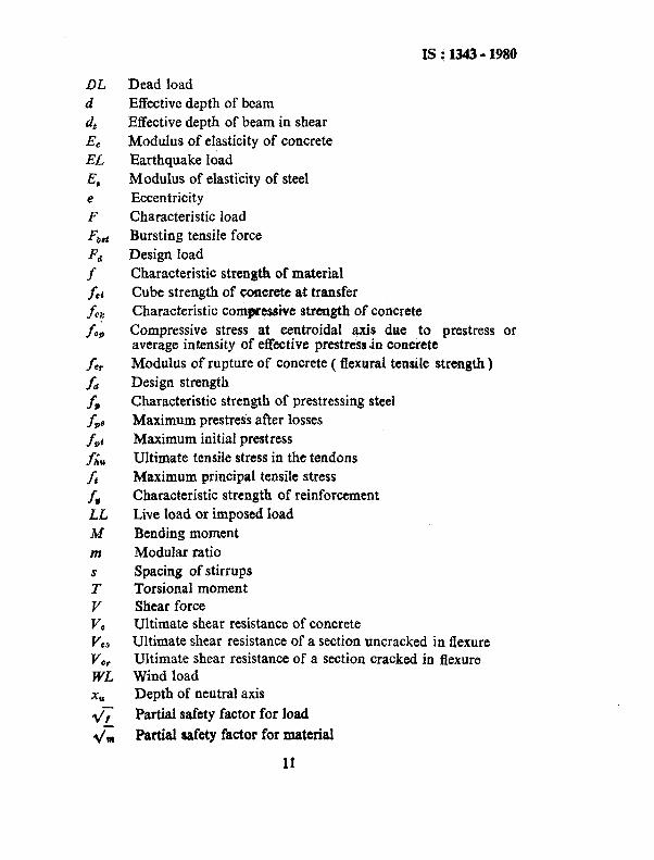
DL d
dt EE EL
E, e F
F bat
7
2
fc9
;
2. f,i f hu h f, LL
M
m
s T V
VI3 voo
VW WL
& -
Dead load Effective depth of beam Effective depth of beam in shear Modulus of elasticity of concrete Earthquake load Modulus of elasticity of steel Eccentricity Characteristic load Bursting tensile force Design load Characteristic strength of material Cube strength of eoncrete at transfer Characteristic compressive strength of concrete Compressive stress at eentroidal axis due to prestress or average intensity of effective prestress in concrete Modulus of rupture of concrete ( flexural tensile strength ) Design strength Characteristic strength of prestressing steel Maximum prestress after losses Maximum initial prestress Ultimate tensile stress in the tendons Maximum principal tensile stress Characteristic strength of reinforcement Live load or imposed load Bending moment Modular ratio Spacing of stirrups Torsional moment Shear force Ultimate shear resistance of concrete Ultimate shear resistance of a section nncracked in flexure Ultimate shear resistance of a section cracked in flexure Wind load Depth of neutral axis
Partial safety factor for load
Partial safety factor for material
11
IS:1343-1980
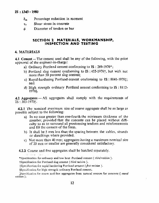
hn Percentage reduction in moment
Tc Shear stress in concrete
# Diameter of tendon or bar
SECTION 2 MATERIALS, INSPECTION AND
4. MATERIALS
WORKMANSHIP, TESTING
4.1 Cement - The cement used shall be any of the following, with the prior approval of the engineer-in-charge:
4 b)
c>
4
Ordinary Portland cement conforming to IS : 269-1976”; Portland slag cement conforming to IS : 4551976t, but with not more than 50 percent slag content; Rapid-hardening Portland cement conforming to IS : 8041-1978$; and High strength ordinary Portland cement conforming to IS : 8112- 19765.
4.2 Aggregates-All aggregates shall comply with the requirements of ‘IS : 383-1970/!.
4.2.1 The nominal maximum size of coarse aggregate shall be as large as possible subject to the following:
a> In-no case greater than one-fourth the minimum thickness of the member, provided that the concrete can be placed without diffi- culty so as to surround all prestressing tendons and reinforcements and fill the corners of the form.
b) It shall be 5 mm less than the spacing between the cables, strands or sheathings where provided. Not more than 40 mm; aggregates having a maximum nominal size of 20 mm or smaller are generally considered satisfactory.
4.2.2 Coarse and fine aggregates shail be batched separately. -. .._.
*Specification for ordinary and low heat Portland cement ( third revision ).
tSpecification for Portland slag cement ( third mision ).
SSpecitication for rapid hardening Portland cement (j~i wision ).
@Specification for high strength ordinary Portland cement.
\/Specification for coarse and fine aggregates from natural sources for concrete ( second reuision ).
12
IS : 1343 - 1980
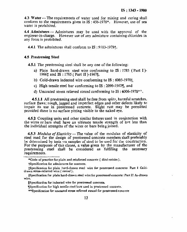
4.3 Water-The requirements of water used for mixing and curing shall conform to the requirements given in IS : 4.561978*. However, use of sea water is prohibited.
4.4 Admixtures - Admixtures may be used with the approval of the engineer-in-charge. However use of any admixture containing chlorides in any form is prohibited.
4.4.1 The admixtures shall conform to IS : 9103-1979t.
4.5 Prestressing Steel
4.51 The prestressing steel shall be any one of the following:
a) Plain hard-drawn steel wire conforming to IS : 1785 (Part I )- 1966$ and IS : 1785 (Part II)-19675,
b) Cold-drawn indented wire conforming to IS : 6003-197011,
c) High tensile steel bar conforming to IS : 2090-19627, and
d) Uncoated stress relieved strand conforming to IS : 6006-1970* *.
4.5.1.1 All prestressing steel shall be free from splits, harmful scratches. surface flaws; rough, jagged and imperfect edges and other defects likely to impair its use in prestressed concrete. Slight rust may be permitted provided there is no surface pitting visible to the naked eye.
4.5.2 Coupling units and other similar fixtures used in conjunction with the wires or ,bars shall have an ultimate tensile strength of not less than the individual strengths of the wires or bars being joined.
45.3 MoMus of Haasticity - The value of the modulus of elasticity of steel used for the design of prestressed concrete members shall preferably be determined by tests on samples of steel to be used for the construction, For the purposes of this clause, a value given by the manufacturer of the prestressing steel shall be considered as fulfilling the necessary requirements.
*Code of practice for plain and reinforced concrete ( third revision ).
tSpecification for admixtures for concrete. SSpecification for plain hard-drawn steel wire for prestressed concrete: Part I Cold-
drawn stress-relieved wire ( rcui~~d ). @pecification for plain hard-drawn steel wire for prestressed concrete: Part II As-drawn
wire. IlSpecification for indented wire for prestressed concrete. $3pecification for high tensile steel bars used in prestressed concrete. **Specification for uncoated stress relieved strand for prestressed concrete
13
IS : 1343 - 1980
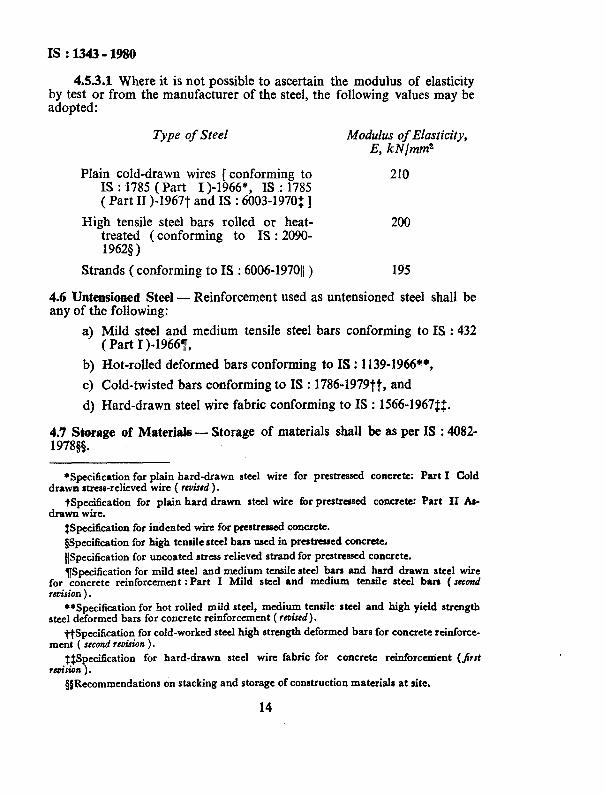
4.5.3.1 Where it is not possible to ascertain the modulus of elasticity by test or from the manufacturer of the steel, the following values may be adopted:
Type of Steel Modulus of Elasticity, E, kN/mm2
Plain cold-drawn wires [conforming to IS : 1785 (Part I)-1966*, IS : 1785 ( Part II )-19671_ and IS : 6003-197011
High tensile steel bars rolled or heat- treated (conforming to IS : 2090- 19621)
210
200
Strands (conforming to IS : 6006-197011) 195
4.6 Untensioned Steel - Reinforcement used as untensioned steel shall be any of the following:
a) Mild steel and medium tensile steel bars conforming to IS : 432 (Part I)-19667,
b) Hot-rolled deformed bars conforming to IS : 1139-1966**,
c) Cold-twisted bars conforming to IS : 1786-1979tt, and
d) Hard-drawn steel wire fabric conforming to IS : 1566-1967$$.
4.7 Storage of Materials - Storage of materials shall be as per IS : 4082- 197855.
*Specification for plain hard-drawn steel wire for prestressed concrete: Part I Cold drawn stress-relieved wire ( revised ) .
tSpec%cation for plain hard drawn steel wire for prestressed concrete: Part II As- drawn wire.
$+xification for indented wire for prestrused concrete.
&Specification for high tensile steel bars used in preatressed concrete.
IlSpecification for uncoated stress relieved strand for prestressed concrete.
BSpecification for mild steel and medium tensile steel bars and hard drawn steel wire for concrete reinforcement : Part I Mild steel and medium tensile steel bars (second revision 1.
**Specification for hot rolled mild steel, medium tensile steel and high yield strength steel deformed bars for concrete reinforcement ( rtied).
ttSpe&fication for cold-worked steel high strength deformed bars for concrete reinforce- ment ( second rcotion )-
t$Specification for hard-drawn steel wire fabric for concrete reinforcement (Jrrt ret&ion ) .
§§Recommendations on stacking and storage of construction materials at site.
14
i-- ‘-.’ ._-_ _- -__
IS : 1343 - 1980
5. CONCRETE
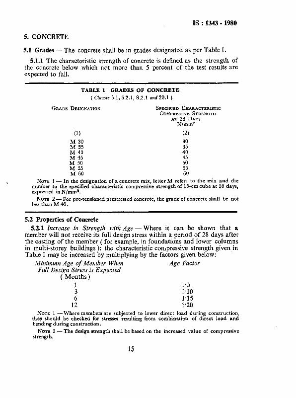
5.1 Grades -- The concrete shall be in grades designated as per Table 1.
5.1.1 The characteristic strength of concrete is defined as the strength of the concrete below which not more than 5 percent of the test results are expected to fall.
TABLE 1 GRADES OF CONCRETE
( Clauses 5.1, 5.2.1, 8.2.1 and 20.1 )
GRADE DESIGNATION SPECIFIED CHARACTERISTIC COMPRESSIVE STRENGTH
AT 28 DAYS N/mm2
(1) (2)
M 30 30 M 35 M 43 :5, M 45 45 M 50 50 M 55 55 M GO GO
NOTE 1 - In the designation of a concrete mix, letter M refers to the mix and the number to the specified characteristic compressive strength of 15-cm cube at 28 days, expressed in N/mm*.
NOTE 2 -For pm-tensioned prcstressed concrete, the grade of concrete shall be not less than M 40.
5.2 Properties of Concrete 5.2.1 Increase in Strength with Age - Where it can be shown that a
member will not receive its full design stress within a period of 28 days after the casting of the member ( for example, in foundations and lower columns in multi-storey buildings ); the characteristic compressive strength given in Table 1 may be increased by multiplying by the factors given below:
Minimum Age of Member When Age Factor Ft4ll Design Stress is Expected
( Months)
: 14 1.10
6 1.15 12 1.20
NOTE 1 -Where members are subjected to lower direct load during construction, they should be checked for stresses resulting from combination of direct load and bending during construction.
NOTE 2 -The design strength shall be based on the increased value of compressive strength.
15
*sll_.._d ” ,_*__. _._._l_.-__-. --
IS : 1343 - 1980
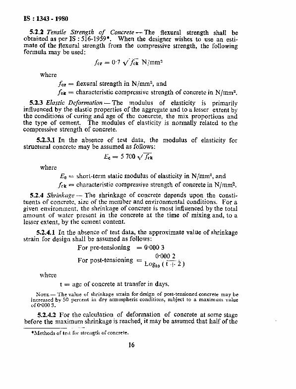
5.2.2 Tensile Strength of Concrete-The flexural strength shall be obtained as per IS : 516-1959*. When the designer wishes to use an esti- mate of the flexural strength from the compressive strength, the following formula may be used:
fcr = 0.7 d/ N/mm2
where fcr = flexural strength in N/mm2, and fck = characteristic compressive strength of concrete in N/mm2.
5.2.3 Elastic Deformation - The modulus of elasticity is primarily influenced by the elastic properties of the aggregate and to a lesser extent by the conditions of curing and age of the concrete, the mix proportions and the type of cement. The modulus of elasticity is normally related to the compressive strength of concrete.
5.2.3.1 In the absence of test data, the modulus of elasticity for structural concrete may be assumed as follows:
-- E c = 5 700 \/ fck
where EC = short-term static modulus of elasticity in N/mm2, and
fCk = characteristic compressive strength of concrete in N/mm2.
5.2.4 Shrinkage - The shrinkage of concrete depends upon the consti- tuents of concrete, size of the member and environmental conditions. For a given environment, the shrinkage of concrete is most influenced by the total amount of water present in the concrete at the time of mixing and, to a lesser extent, by the cement content.
5.2.4.1 In the absence of test data, the approximate value of shrinkage strain for design shall be assumed as follows:
For pre-tensioning = O*OOO 3 0.000 2
For post-tensioning = ~------- Log,, ( t +- 2 )
where
t = age of concrete at transfer in days.
NOTE - The value of shrinkage strain for design of post-tensioned concrete may be increased by 50 percent in dry atmospheric conditious, subject to a maximum value of@0003.
5.2.4.2 For the calculation of deformation of concrete at some stage before the maximum shrinkage is reached, it may be assumed that half of the
*Methods of test for strength of concrete.
16
IS : 1343 - 1980
shrinkage takes place during the first month and that about three-quarters of the shrinkage takes place in first six months after commencement of drying.
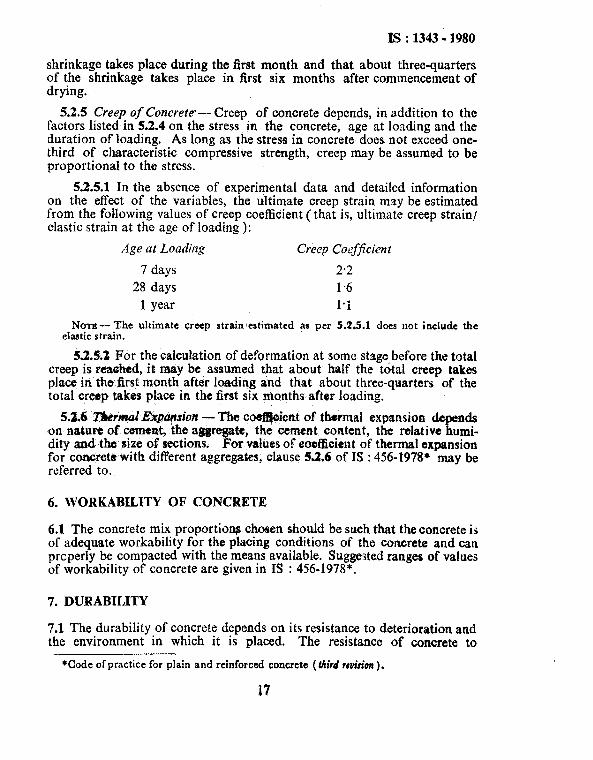
5.2.5 Creep of Concrete’--- Creep of concrete depends, in addition to the factors listed in 5.2.4 on the stress in the concrete, age at loading and the duration of loading. As long as the stress in concrete does not exceed one- third of characteristic compressive strength, creep may be assumed to be proportional to the stress.
5.2.5.1 In the absence of experimental data and detailed information on the effect of the variables, the ultimate creep strain may be estimated from the following values of creep coefficient (that is, ultimate creep strain/ elastic strain at the age of loading ):
Age at Loading Creep Co cfjcien t
7 days 2.2 28 days 1.6
1 year l*i
NOTE- The ultimate creep strain estimated as per 5.2.5.1 does not include the elastic strain.
5.2.5.2 For the calculation of deformation at some stage before the total creep is Pea&d, it may be assumed that about half the t&al creep takes place in the first month after loading and that about three-quarters of the total cresp takes place in the Grst six months after loading.
5.2.6 ~!&WHUZ~JMZ+O~ - The coafflolent of t&ma1 expansion depends on ntiure d cement, {he aggregate, thb cement content, the relative humi- dity and. the,aize of sections. For valucts of eoe&eient of thermal expansion for concrete with different aggregates, clause 53.6 of IS : 4.56-19781 may be referred to.
6. WORKABiLITY OF CONCRETE
6.1 The concrete mix proportion+s chosen should be such that the concrete is of adequate workability for the placing conditions of the concrete and can prcperly be compacted with the means available. Suggested ranges of values of workability of concrete are given in IS : 456-1978*.
7. DURABILITY
7.1 The durability of concrete depends on its resistance to deterioration and the environment in which it is placed. The resistance of concrete to
*Code of practice for plain and reinforced concrete ( Wd wision ),
17
IS : 1343 - 1980
weathering, chemical attack, abrasion, frost and fire depends largely upon its quality and constituent materials. The strength alone is not a reliable guide to the quality and durability of concrete; it must also have an adequate cement content and a low water-cement ratio.
7.1.1 One of the main characteristics influencing the durability of concrete is its permeability. With strong, dense aggregates, a suitably low permeability is achieved by having a sufficiently low water-cement ratio, by ensuring as thorough compaction of the concrete as possible and by ensuring sufficient hydration of cement through proper curing methods. Therefore, for given aggregates, the cement content should be suflicient to provide adequate workability with a low water-cement ratio so that concrete can be thoroughly compacted with the means available.
7.2 Appendix A provides guidance regarding minimum cement content and permissible limits of chloride and sulphate in concrete.
8. CONCRETE MIX PROPORTIONING
8.1 n?ix Proportion -The mix proportions shall be selected to ensure &at the workability of the fresh concrete is suitable for the conditions of handling and placing, so that after compaction it surrounds all prestressing tendons and reinforcements if present and completely fills the formwork. When concrete is hardened, it shall have the required strength, durability and surface finish.
8.1.X The determination of the proportions of cement, aggregates and water to att4n the required strengths shall be made by designing the concrete mix. Such concrete shall be called ‘Design mix concrete’.
For prestressed concrete construction, only ‘Design mix concrete’ shall be used. The cement content in the mix should preferably not exceed 530 kp4nR.
8.1.2 Information Rcqhd - In specifying a particular grade of cot- Crete, the information to be included shall be:
a) Grade designation, b) Type of cement, c) Maximum nominal size of aggregates, d) Minimum cement content, e) Maximum water-cement ratio, and f) Workability.
8.1.2.1 In appropriate circumstances, the following additional infor- mation may be specified:
a) Type of aggregate,
18
-
IS : 1343. 1980
b) Maximum cement content, and c) Whether an admixture shall or shall not be used and the type of
admixture and the conditions of use.
8.2 Design Mix Concrete
8.2.1 The mix shall be designed to produce the grade of concrete having the required workability and a characteristic strength not less than appro- priate values given in Table 1. The procedure given in Indian Standard Recommended guidelines for concrete mix design ( under preparation ) may be followed.
9. PRODUCTION AND CONTROL OF CONCRETE
9.1 Quality of Materials - Tt is essential for designers and construction engineers to appreciate that the most effective use of prestressed concrete is obtained only when the concrete and the prestressing steel employed are of high quality and strength.
9.2 The provisions of 9 of IS : 456-1978” shall apply; except that no hand- mixing shall be permitted in prestressed concrete work.
10. FORMWORK
10.1 The provisions of 10 of IS : 4S6-197g* shall generally apply. In addition, 10.1.1 shall also apply.
10.1.1 Moulds for pre-tension work shall be sufficiently strong and rigid to withstand,, without distortion, the effects of placing and compacting concrete as well as those of prestressing in the case of manufacture by the individual mould process where the prestressing tendon is supported by the mould before transfer.
11. ASSEMBLY OF PRESTRESSING AND REINFORCING STEEL
11.1 Prestressing Steel
11.1.1 Straightrnit~g
11.1.1.1 The wire, as supplied, shall preferably be self-straightening when uncoiled. If it is not so, the wire may need to be mechanically straightened before use. In this event, care shali be taken to avoid alteration in the properties of the wire during the straightening process and preferably a test shall be made on a sample of the wire after straightening.
*Code of practice for plain and reinforced concrete ( third reuision ).
19
L... . .
IS : 1343 - 1980
11.1.1.2 In the case of high tensile alloy steel bars, any straightening ( or bending if the design provided for curved bars) shall be carried out by means of a bar-bending machine. Bars shall not be bent when their temperature is less than 10°C.
11.1.1.3 In no case heat shall be applied to facilitate straightening or bending of prestressing steel.
11.1.2 Arrangement of Wires and Positioning
11.1.2.1 All prestressing steel shall be carefully and accurately located in the exact positions shown in the design drawings. The permissible tolerance in the location of the prestressing tendon shall be f5 mm. Curves or bends in prestressing tendon required by the designer shall be gradual and the prestressing tendon shall not be forced around sharp bends or be formed in any manner which is likely to set up undesirable secondary stresses.
11.1.2.2 The relative position of wires in a cable, whether curved or straight, shall be accurately maintained by suitable means such as sufficiently rigid and adequately distributed spacers.
11.1.2.3 In the case of post-tension work, the spacing of wires in a cable shall be adequate to ensure the free flow of grout.
11.1.2.4 The method of fixing and supporting the steel in the mould or the formwork shall be such that it is not displaced during the placing or compaction of the concrete or during tensioning of the steel.
11.1.2.5 The type of fixtures used for positioning the steel shall be such that it.does not give rise to friction greater than that assumed in the design.
11.1.3 Jointing
11.1.3.1 High tensile wire other than hard-drawn wire may be joined together by suitable means provided the strength of such joints is not less than the individual strengths of the wires being joined. Hard-drawn wire used in prestressed concrete work shall be continuous over the entire length of the tendon.
11.1.3.2 High tensile steel bars may be joined together by means of couplings, provided the strength of the coupling is such that in a test to destruction, the bar shall fail before the coupling.
11.1.3.3 Welding shall not be permitted in either wires or bars.
11.1.4.1 All cutting to length and trimming of the ends of wires shall be done by suitable mechanical or flame cutters. Where flame
20
IS :1343-1980
cutters are used, care shall be taken to ensure that the Aame does not come into contact with other stressed wires or concrete.
11.1.4.2 Bars shall preferably be ordered to the exact length required. Any trimming required shall be done only after the bar has been tensioned and the grout has set; it shall then be carried out in accordance with 11.1.4.1.
11.1.5 Protection of Prestressing Steel and Anchorages - In all construc- tions of the post-tensioned type, where prestressing is initially carried out without bond, the prestressing tendon shall, at a subsequent date and generally not later than one week after prestressing, be given and adequate protection against corrosion.
11.1.5.1 Internal prestressitzg steel - Internal prestressing steel is best protected by a cement or cement-sand grout preferably in colloidal form. Care shall be taken to prevent segregation and, for that purpose, only fine sand shall be used.
The grout shall be placed under pressure, and it shall be ensured that the entire space between the duct and the prestressing tendon is properly filled with grout.
Where small ducts are encountered, it is advisable that water is flushed through prior to grouting, care being taken to see that all water is subsequently displaced by grout. In the case of butted assemblies, flushing with water shall be carried out only after the jointing material has properly hardened.
Injection shall proceed from one end or preferably in case of curved ducts from the lowest point of the curve, and shall be continued until the grout overflows from the other end.
11.1.5.2 External prestressing steel - The protection of external prestressing steel is usually best done by encasing the tensioned wires, cables or bars in a dense concrete secured to the main concrete, for example, by wires left projecting from the latter. If a cement-sand mix is used, the cover provided and its density should be adequate to prevent corrosion.
Alternatively, the steel may be encased in bitumen or, where the steel is accessible for inspection and maintenance, paint protection may be provided.
11.1.5.3 The anchorage shall be adequately protected against damage or corrosion soon after the completion of the final stressing and grouting operations.
11.1.6 Cover
11.1.6.1 In pre-tensioned work, the cover of concrete measured from the outside of the prestressing tendon shall be at least 20 mm.
21
xs ; 1343 - 1980
11.1.6.2 In post-tensioned work, where cables and large-sized bars are used, the minimum clear cover from sheathing/duct shall be at least 30 mm or the size of the cable or bar whichever is bigger.
11.1.6.3 Where prestressed concrete members are located in aggressive environment, the cover specified under 11.1.6.1 and 11.1.6.2 shall be increased by 10 mm.
11.1.7 Spacing
11.1.7.1 In the case of single wires used in pre-tension system, the minimum cIear spacing shall not be less than greater of the following :
a) 3 times diameter of wire, and b) 13 times the maximum size of aggregate.
11.1.3.2 In the case of cables or large bars, the minimum clear spacing ( measured between sheathings/ducts, wherever used ) shall not be less than greater of the following:
a) 40 mm, b) Maximum size of cable or bar, and c) 5 mm plus maximum size of aggregate.
11.1.8 Grouped Cables
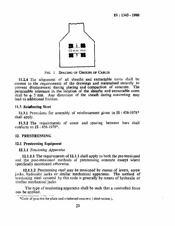
11.1.8.1 Cables or ducts may be grouped together in groups of not more than four as shown in Fig. 1.
11.1.8.2 The minimum clear spacing between groups of cables o’r ducts of grouped cables shall be greater of the following:
a) 40.mm, and b) 5 mm plus maximum size of aggregate.
The vertical distance between groups shall not be less than 50 mm ( see Fig. 1 ).
11.2 Sheaths and Extractable Cores
11.2.1 Sheaths shall be sufficiently water-tight to prevent concrete laitance penetrating in them in quantities likely to increase friction. Special care shall be taken to ensure watertightness at the joints.
11.2.2 They shall be preferably machine-manufactured and have bores sufficiently large to allow being easily threaded on to the cable or bar in long lengths.
11.2.3 The tubes or sheaths shall be of such strength as not to be dented or deformed during handling or concreting.
22
IS : 1343 - 1980
FIG. 1 SPACING OF GRCWPS OF CABLES
11.2.4 The alignment of all sheaths and extractable cores shall be correct to the requirements of the drawings and maintained securely to prevent displacement during placing and compaction of concrete. The permissible tolerance in the location of the sheaths and extractable cores shall be f 5 mm. Any distortion of the sheath during concreting may lead to additional friction.
11.3 Reirt#orcing Steel
11.3.1 Provisions for assembly of reinforcement given in IS : 456-1978* shall apply.
11.3.2 The requirements of cover and spacing between bars shall conform to IS : 456-1978’.
12. PRESTriESSING
12.1 Prestressing Equipment
12.1.1 Tensioning Apparatus
12.1.1.1 The requirements of 12.1.1 shall apply to both the pre-tensioned and the post-tensioned methods of prestressing concrete except where specifically mentioned otherwise.
12.1.1.2 Prestressing steel may be tensiondd by means of levers, screw jacks, hydraulic jacks or similar mechanical apparatus. The method of tensioning steel covered by this code is generally by means of hydraulic or similar mechanical jacks.
The type of tensioning apparatus shall be such that a controlled force can be applied. -____---.
*Code of practice fix plain and reinforced colywe ( third rrvision ).
23
hhw.,~~_.~.---- l___,___ .,. ___ _.
IS : 1343 - 1980
The tensioning apparatus shall not induce dangerous secondary stresses or torsional effects on the steel, concrete, or on the anchorage.
12.1.1.3 The anchorage provided for the temporary gripping of wires or bars on the tensioning apparatus shall be secure and such as not to damage the wire or bar.
12.1.1.4 Devices attached to the tensioning apparatus for measuring the applied force shall be such that they do not introduce errors exceeding 5 percent.
12.1.2 Temporary Gripping Device - Prestressing tendons may be gripped by wedges, yokes, double cones or any other approved type of gripping devices. The prestressing wires may be gripped singly or in groups. Gripping devices shall be such that in a tensile test, the wire or wires fixed by them would break before failure of the grip itself.
12.1.3 Releasing Device - The releasing device shall be so designed that during the period between the tensioning and release, the tension in the prestressing elements is fully maintained by positive means, such as exter- nal anchoragis. The device shall enable the transfer of prestress to be carried out gradually so as to avoid large difference of tension between wires in a tendon, severe eccentricities of prestress or the sudden application of stress to the concrete.
lkl.4 Anchorage
12.1.4.1 The anchorage may consist of any device, patented or other- wise, which complies with the requirements laid down under 12.1.4.2 to 12.1.4.6.
12.1.4.2 The anchoring device shall be capable of holding without more than nominal slip, the prestressing tendon subjected to a load midway between the proposed initial prestressing load and the ultimate strength of the pnstressing tendon.
12.1.4.3 The anchoring device shall be strong enough to resist in all respects a force equal to at least the breaking strength of the prestressing tendon it anchors.
12.1.4.4 The anchorage shall transfer effectively and distribute, as evenly as possible, the entire force from the prestressing tendon to the concrete without inducing undesirable secondary or local stresses.
12.1.4.5 The anchorage shall be safe and secure against both dynamic and static loads as well as against impact.
12.1.4.6 The anchorage shall have provision for the introduction of a suitable protective medium, such as cement grout, for the protection of the prestressing steel unless alternative arrangements are made.
24
IS :1343-1980
12.2 Procedure for Tensioning and Transfer
12.2.1 Stressing
12.2.1.1 The tensioning of prestressing tendons shall be carried out in a manner that will induce a smooth and even rate of increase of stress in the tendons.
12.2.1.2 The total tension imparted to each tendon shall conform to the requirements of the design. No alteration in the prestressing force in any tendon shall be allowed unless specifically approved by the designer.
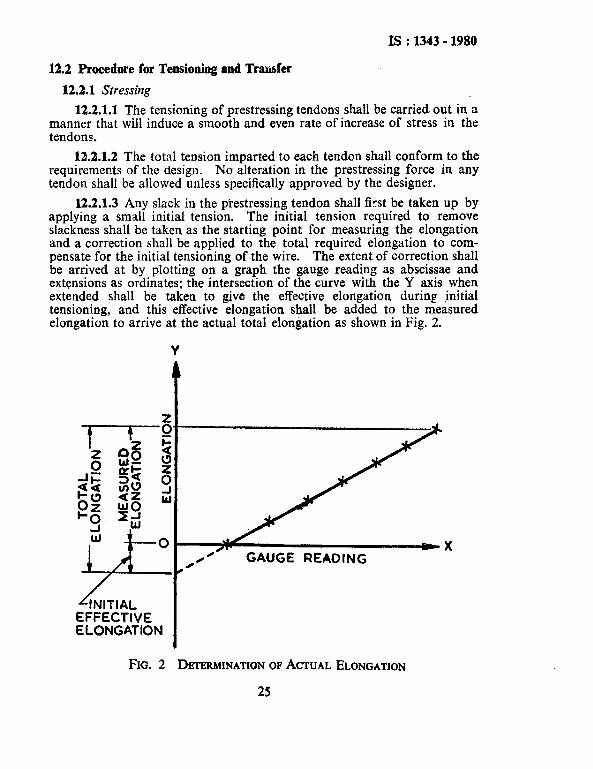
12.2.1.3 Any slack in the ptestressing tendon shall first be taken up by applying a small initial tension. The initial tension required to remove slackness shall be taken as the starting point for measuring the elongation and a correction shall be applied to the total required elongation to com- pensate for the initial tensioning of the wire. The extent of correction shall be arrived at by plotting on a graph the gauge reading as abscissae and extensions as ordinates: the intersection of the curve with the Y axis when extended shall be taken to give the effective elongation during initial tensioning, and this effective elongation shall be added to the measured elongation to arrive at the actual total elongation as shown in Fig. 2.
EFFECTIVE ELONGATION
FIG. 2 DETERMINATION OF ACTUAL ELONGATION
IS : 1343 - 1980
12.2.1.4 When two or more presiressing tendons are to be tensioned simultaneously, care shall be taken to ensure that all such tendons are of the same length from grip to grip. The provision shall be more carefully observed for tendons of a length smaller than 7.5 m.
12.2.1.5 The placement of cables or ducts and the order of stressing and grouting shall be so arranged that the prestressing steel, when tensioned and grouted, does not adversely affect the adjoining ducts.
12.2.2 Measurement of Prestressing Force
12.2.2.1 The force induced in the prestressing tendon shall be determin- ed by means of gauges attached to the tensioning apparatus as well as by measuring the extension of the steel and relating it to its stress-strain curve. It is essential that both methods are used jointly so that the inaccuracies to which each is singly susceptible are minimized. Due allowance shall be made for the frictional Josses in the tensioning apparatus.
12.2.2.2 The pressure gauges or devices attached to the tensioning apparatus to measure the force shall be periodicaliy calibrated to ensure that they do not at any time introduce errors in reading exceeding 2 percent.
12.2.2.3 In measuring the extension of prestressing steel, any slip which may occur in the gripping device shall be taken into consideration.
12.2.3 Breakage of Wires - The breakage of wires in any one prestressed concrete member shall not exceed 2.5 percent during tensioning. Wire breakages after anchorage, irrespective of percentage, shall not be condoned without special investigations.
12.2.4 Trarisfer of Prestressing Force
12.2.4.1 The transfer of the prestress shall be carried out gradually so as to avoid large differences of tension between wires in a tendon, severe eccentricities of prestressing force and the sudden application of stress to the concrete.
12.2.4.2 Where the total prestressing force in a member is built up by successive transfers to the force of a number of individual tendons on to the concrete, account shall be taken of the effect of the successive prestressing.
12.2.4.3 In the long line and similar methods of prestressing, when the transfer is made on several moulds at a time, care shall be taken to ensure that the prestressing force is evenly applied on all the moulds, and that the transfer of prestress to the concrete is uniform along the entire length of the tension line.
12.3 Grouting
12.3.1 The requirements of the grout are fluidity and low sedimentation ( or bleeding) in the plastic state. In the hardened state, it shall be dense,
26
IS : 1343 - 3980
have low shrinkage and be durable. The grouting technique adopted should be such that it can be carried out easily and effectively.
12.3.2 Grout shall be made from any of the cements specified in 4.1 and water conforming to 4.3. Fine sand passing 150 pm IS Sieve may be added only for ducts of very large size. If permitted by the engineer-in charge, admixtures may be added to improve the performance of the grout. The water-cement ratio for neat cement grouts should be approximately 0.50 by mass, but should in no case exceed 0.55 by mass.
12.3.2.1 The compressive strength of 100 mm cubes of the grout shall not be less than 17 N/mm2 at 7 days. Cubes shall be cured in a moist atmoshphere for the first 24 hours, and subsequently in water.
12.3.3 Grouting Equipment
12.3.3.1 The mixer shall be of a high speed mixing type, capable of mixing with high local turbulence while imparting only a slow motion to the body of the grout. A grout screen should preferably be fitted.
12.3.3.2 The pump and the injection equipment shall be capable of continuous operation with little, if any, pressure variation and shall have a system for recirculating the grout while actual grouting is not in progress. No compressed air system should be used for grouting work. The pumping equipment shall be able to deliver the grout at a nozzle pressure of at least 0.7 N/mm2.
12.3.3.3 All piping to and from the grout pump shall have a minimum of bends, valves, and changes in diameter and the delivery hose shall be as short as practicable.
12.3.3.4 All piping, pumping and mixing equipment should be thoroughly washed with clean water after each series of operations or more frequently if necessary. In any case the intervals between the washings shall not exceed 3 hours.
12.3.4 Mixing - Water shall be measured and added to the mixer first, followed by cement. When these are thoroughly mixed, the additive and sand, if any, shall be added. When all the ingredients have been added, mixing shall continue for at least two minutes.
12.3.5 Duct Preparation - Ducts shall be kept clean at all times. Un- wanted opening at anchorages and in any other locations shall be sealed before grouting commences.
In all long ducts, or in any duct where considerable changes of level occur and in any large diameter ducts, grout vents shall be provided at all crests and at intervals of 20 m to 30 m so that grout can be injected succes- sively through vents as the grout flows along the ducts. Where water is likely to enter ducts, valley vents shall also be provided for drainage.
27
IS : 1343 - 1980
12.3.6 Grout Injection - Grouts should be injected from the lowest point or ‘ uphill ’ wherever practicable so that air and water in the duct, being less dense than the grout, will be pushed ahead of the grout mix and be less liable to become entrapped in the grout mix.
Grout mix shall be allowed to flow through vent openings until its consistency is equivalent to that of the grout injected. Vent openings shall then be firmly closed one after the other in the direction of flow. Once good grout mix has commenced to flow freely from the end or ends of the duct, that end or ends shall be closed and the pressure built up inside the duct to 0.7 N/mm’ before closing the injection end.
In the case of large ducts where pressure grouting cannot be used, a standpipe or vent pipe shall be provided and kept topped up with cement for an hour or two to replace grout losses due to wastage and subsidence at the termination of grouting operation.
13. TRANSPORTING, PLACING, COMPACTING AND CURING
13.1 Provisions given in IS : 456-1978* shall apply. In addition, the provisions given in 13.1.1 and 13.1.2 shall also apply.
13.1.1 The use of construction joints in prestressed concrete work should preferably be avoided. But, if found necessary, their position and arrange- ment shall be predetermined by the designer.
13.1.2 Jointing of Butfed Assemblies
13.1.2.1 The joints of butted assemblies shall be made of either cement, grout or cement mortar or concrete. Grouting shall be used for joints up to 12 mm thick. For joints thicker than 12 mm and preferably for thick- nesses between 18 and 25 mm, mortar shall be used. The mortar which may be made of one part cement and one-and-a-half parts sand shall be of a dry consistency and shall be packed hard in layers so that it rings true. Where joints exceeding 75 mm are encountered, thejoint shall be made up of concrete.
13.1.2.2 The stressing operations may be carried out in case of mortar joints immediately after placing the mortar but the stress in the mortar shall not exceed 7.0 N/mma. In the case of grouted joints and concrete joints the allowable stress in the first 24 hours after placing of the grout or concrete in the joint shall approximate as closely as possible to the strength of the grout or concrete used.
13.1.2.3 The holes for the prestressing tendons shall be accurately located and shall be in true alignment when the units are put toge;her.
13.1.2.4 Full tensioning shall not be carried out until the strength of the concrete or morta: in the joint has reached twice the transfer stress.
*Code of practice for plain and reinforced concrete ( third r&ion ),
IS : 1343 - 1980
14. CONCRETING UNDER SPECIAL CONDITIONS
14.1 Work in Extreme Weather Conditions - During hot or cold weather, the concreting should be done as per the procedure set out in IS : 7861 (Part I)-1975* or IS : 7861 ( Part II)-1981t.
15. SAMPLING AND STRENGTH TEST OF CONCRETE
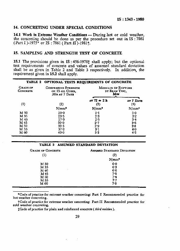
15.1 The provisions given in IS : 456-1978$ shall apply; but the optional test requirements of concrete and values of assumed standard deviation shall be as given in Table 2 and Table 3 respectively. In addition, the requirement given in 15.2 shall apply.
TABLE 2 OPTIONAL’ TESTS REQUIREMNTS O# CONCRETE
GRADE OF COMPRESSWE STRENGTH MODIJLUS OF RUPTURE CONCRETE ON 15 cm CUBFS, BY BEAM TEST,
Min AT 7 DAYS w
(1)
M 30 M 35 M 40 M 45 M 50 M 55 M 60
~-72 I 2 h AT --- 7 DAYS (2) (3) (4)
N/mm’ N/mm’ N/mm’
2@0 23.5 22::
3-o
27-o
30.0 Z.-f
;:3
33.5 2.9 ;:;
37.0 40-o 33:; ;:;
TABLE 3 ASSUMED STANDARD DEVIATION
GRADE OF CONCRETE ASSUMED STANDARD DEVIATION
(1) c-9 N/mm’
M 30 6.0
M 35 M 40 2::
M 45 7.0 M 50 M55 ;:;
M 60 7.8
*Code of practice for extreme weather concreting: Part I Recommended practice for hot weather concreting.
tCode of practice for extreme weather concreting: Part II Recommended practice for cold weather concreting.
$Code of practice for plain and reinforced concrete ( third revision ).
29
IS : 1343 - 1980
15.2 Concrete Strength at Transfer - In addition to the tests required as per 15.1, additional cube tests should be conducted at appropriate intervals to ensure that the concrete strength in the member at transfer conforms to the design requirements. The frequency of sampling and number of cubes should be decided by the engineer-in-charge. The sampling of concrete should preferably be at the point of placing and the cubes should. be stored as far as possible under the same conditions as the concrete in the members.
16. ACCEPTANCE CRITERIA
16.1 The provisions of IS : 456-1978* shall apply.
17. INSPECTION AND TESTING OF STRUCTURES
17.1 The provisions of IS : 456-1978* shall apply, except for the following:
For type 1 and type 2 structures ( see 19.3.2 ), if within 24 hours of removal of the imposed load, the structure does not recover at least 85 percent of the deflection under superimposed load, the test may be repeated after a lapse of 72 hours. If the recovery is less than 90 percent, the structure shall be deemed to be unacceptable.
For type 3 structures (see 19.3.2), if within 24 hours of the imposed load, the structure does not recover at least 7.5 percent of the deflection under superimposed load, the test may be repea- ted after a lapse of 72 hours. If the recovery is less than 80 percent, the structure shall be deemed to be unacceptable.
SECTION 3 GENERAL DESIGN REQUIREMENTS
18. GENERAL DESIGN REQUIREMENTS
18.1 The general design requirements for design of prestressed concrete structures shall be as per clauses 17 to 24 of Section 3 of IS : 456-1978* except as modified and supplemented in 18.2 to 18.6.5.
18.2 The effects of prestress shall also be taken into account in assessing loads and forces.
18.3 The deductions for prestressing tendons as in 18.3.1 shall be consi- dered for the determination of area, centroid and moment of inertia of the cross-section.
*C&de of practice for plain and reinforced concrete ( third revision ).
30
IS : 1343 - 1980
18.3.1 Deductions for Prestreqsing Tendons - In calculating area, centroid and moment of inertia of a cross-section, deduction for prestressing tendons shall be made as follows:
a) In the case of pre-tensioned members, where the prestressing tendons are single wires distributed on the cross-section or strands of wires of relatively small cross-sectional area, allowance for the prestressing tendons need not be made. Where allowance is made, it shall be on the basis of (m-l ) times the area of the prestressing tendons, m being the modular ratio.
b) In the case of post-tensioned members, deductions shall invariably be made for prestressing tendons, cable ducts or sheaths and such other openings whether they are formed longitudinally or trans- versely. These deductions need not, however, be made for deter- mining the effect of loads applied after the ducts, sheaths or openings have been grouted or filled with concrete. Where such deductions are not made, a transformed area equivalent to ( m-l ) times the area of the prestressing tendon shall be taken in calcula- tion, m being the modular ratio.
NOTE -m shall be calculated as Es/EC; for values of Es and EC, JM 4.5.3.1 and 5.2.3.1 respectively. Wherever necessary, creep effects shall also be taken into consideration.
18.4 Instability During Erection - In evaluating the slenderness effects during lifting of slender beams, the following factors require consideration:
a) Beam geometry, b) Location of lifting points, c) Method of lifting, and d) Tolerances in construction.
All beams, which are lifted on vertical or inclined slings, shall be checked for lateral stability and lateral moment on account of tilting of beam due to inaccuracies in location of lifting points, and due to the lateral bow.
For calculating the factor of safety against lateral instability yt reference may be made to specialist literature; the factor shall not be less than two.
For determining the lateral moment due to tilting, realistic values which are not likely to be exceeded in practice shall be assumed for the eccentricity of lifting points and the lateral bow. The maximum tensile stress for yi/yi - 1 times the lateral moment due to tilting shall not exceed 1.5 N/mm2.
18.5 Prestressing Requirements 18.5.1 Maximum Initial Prestress - At the time of initial tensioning, the
maximum tensile stress f,i immediately behind the anchorages shall not exceed 80 percent of the ultimate tensile strength of the wire or bar or strand.
31
IS :1343-1980
18.52 Losses in Prestress - While assessing the stresses in concrete and steel during tensioning operations and later in service, due regard shall be paid to all losses and variations in stress resulting from creep of concrete, shrinkage of c,oncrete, relaxation of steel, the shortening ( elastic deforma- tion) of concrete at transfer, and friction and slip of anchorage. Unless otherwise determined by actual tests, allowance for these losses shall be made in accordance with the values specified under 18.5.2.1 to 18.5.2.6.
In computing the losses in prestress when untensioned reinforcement is present, the effect of the tensile stresses developed by the untensioned reinforcement due to shrinkage and creep shall be considered.
18.5.2.1 Loss of prestress due to creep of concrete - The loss of pre- stress due to creep of concrete under load shall be determined for all the permanently applied loads including the prestress.
The creep loss due to live load stresses, erection stresses and other stresses of short duration may be ignored. The loss of prestress due to creep of concrete is obtained as the product of the modulus of elasticity of the prestressmg steel ( see 4.5.3 ) and the ultimate creep strain of the concrete fibre (see 5.2.5.1 ) integrated along the line of centre of gravity of the prestressing steel over its entire length.
The total creep strain during any specific period shall be assumed for all practical purposes, to be the creep strain due to sustained stress equal to the average of the stresses at the beginning and end of the period.
X5.2.2 Loss of prestress due to shrinkage of concrete- The loss of prestress due to shrinkage of concrete shall be the product of the modulus of elasticity of steel ( see 4.5.3) and the shrinkage strain of concrete ( see 5.2.4.1).
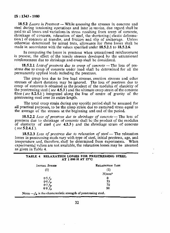
18.5.2.3 ‘Loss of prestress due to relaxation of steel - The relaxation losses in prestressing steels vary with type of steel, initial prestress, age, and temperature and, therefore, shall be determined from experiments. When experimental vaiues are not available, the relaxation losses may be assumed as given in Table 4.
TABLE 4 RELAXATION LOSSES FOR PRESTRESSING STEEL AT 1000 Ii AT 27°C
INITIAL STREW RELAXATION Loss
(1) C-9 N/mm*
@5f28 0
0.6 /9 35
@7f, 70
0’8 I9 90
NOTE -f, is the characteristic strength of prestressing steel.
32
IS :1343-l!Mo
For tendons at higher temperatures or subjected to large lateral loads, greater relaxation losses as specified by the engineer-in-charge shall be allowed for. No reduction in the value of the relaxation losses should be rnade for a tendon with a load equal to or greater than the relevant jacking force that has been applied for a short time prior to the anchoring of the tendon.
18.5.2.4 Loss of prestrcss due to shortening of concrete - This type of loss occurs when the prestressing tendons upon release from tensioning devices cause the concrete to be compressed. This loss is proportional to the modular ratio and initial prestress in the concrete and shall be calcula- ted as below, assuming that the tendons are located at their centroid:
a) For pretensioning, the loss of prestress in the tendons at transfer shall be calculated on a modular ratio basis using the stress in the adjacent concrete.
b) For members with post-tensioned tendons which are not stressed simultaneously, there is a progressive loss of prestress during transfer due to the gradual application of the prestressing forces. This loss of prestress should be calculated on the basis of half the product of the stress in the concrete adjacent to the tendons averaged along their lengths and the modular ratio. Alternatively, the loss of prestress may be exactly computed based on the sequence of tensioning.
18.5.2.5 Loss of prestress due to slip in anchorage - Any loss of pre- stress which may occur due to slip of wires during anchoring or due to the strain of anchorage shall be allowed for in the design. Loss due to slip in anchorage is of special importance with short members and the necessary additional e!ongation should be provided for at the time of tensioning to compensate for this loss.
18.5.2.6 Loss ofprestress due to friction - The design shall take into consideration all losses in prestress that may occur during tensioning due to friction between the prestressing tendons and the surrounding concrete or any fixture attached to the steel or concrete.
For straight or moderately curved structures, with curved or straight cables, the value of prestressing force P, at a distance x metres from ten- sioning end and acting in the direction of the tangent to the curve of the cable, shall be calculated as below:
p, = Poe-- (L”=+kx)
where P, = prestressing force in the prestressed steel at the tensioning
end acting in the direction of the tangent to the curve of the cable,
33
IS : 1343 - 1980
CL=
i*=
cumulative angle in radians through which the tangent to the cable profile has turned between any two points under consideration, coefficient of friction in curve; unless otherwise proved by tests, ,.A may be taken as:
0.55 for steel moving on smooth concrete, 0.30 for steel moving on steel fixed to duct, and O-25 for steel moving on lead,
k = coefficient for wave effect varying from 15 x 1O-4 to 50 x 1O-4 per metre.
NOTE 1 - Expansion of the equation for P, for small values of (pa+&) maybeP,= P,( 1 - ~J.cc---x).
NOTE 2 -In circular constructions, where circumferential ten- dons are tensioned by jacks, values of P for calculating friction may be taken as:
@45 for steel moving in smooth concrete, 0.25 for steel moving on steel bearers fixed to the concrete, and 0.10 for steel moving on steel rollers.
NOTE 3 - The effect of reverse friction shall bc taken into consideration in such cases where the initial tension annlied to a prestressing tendon is partially released and action of-friction in the reverse direction causes an alteration in the distribution of stress along the length of the tendon.
18.6 Considerations Affecting Design Details
18.6.1 Transmission Zqpe in Pre-tensioned Members
18.6.1.1 Trunsmission length - The considerations affecting the trans- mission length shall be the following:
4
b)
The transmission length depends on a number of variables, the most important being the strength of concrete at transfer, the size and type of tendon, the surface deformations of the tendon, and the degree of compactness of the concrete around the tendon. The transmission length may vary depending on the site condi- tions and therefore should be determined from tests carried out under the most unfavourable conditions. In the absence of values based on actual tests, the following values may be used, provided the concrete is well-compacted, and its strength at transfer is not less than 35 N/mm2 and the tendon is released gradually:
I) For plain and indented wire lOOl$ 2) For crimped wires 656, 3) Strands 304
NOTE 1 - @ is the diameter of the tendon.
NOTE 2 - The recommended values of transmission length apply to wires of diameter not exceeding 5 mm and strands of diameter not exceeding 18 mm.
34
c)
4
18.6.2
IS : 1343 - 1980
The development of stress in the tendon may be assumed to vary parabolically along the length of the member.
For general guidance, it is recommended that one-half of the trans- mission length shall overhang the support in a simply supported beam. Where there is end-fixing, the whole of the transmission length shall overhang.
End Zone
18.6Al Bearing strc.rs
4
b)
C)
f >
On the areas immediately behind external anchorages, the per- missible unit bearing stress on the concrete, after accounting for atI lossesdue to relaxation of steel, elastic shortening, creep of concrete, slip and/or seating of anchorages, etc, shall not exceed -.
0.48 fci 2/
A y- or 0.8 fci whichever is smaller, where fci is the sun
cube strength at transfer, ADr is the bearing area and A,,, is the punching area.
During tensioning, the allowable bearing stress specified in a) may be increased by 25 percent, provided that this temporary value does not exceed fCi.
The bearing stress specified in (a) and (b) for permanent and tem- porary bearing stress may be increased suitably if adequate hoop reinforcement complying with IS : 456-1978”: is provided at the anchorages.
When the anchorages are embedded in concrete, the bearing stress shall be investigated after accounting for the surface friction between the anchorage and the concrete.
The effective punching area shall generally be the contact area of the anchorage devices which, if circular in shape, shail be replaced by a square of equivalent area. The bearing area shall be the maximum area of that portion of the member which is geometri- cally similar and concentric to the effective punching area.
Where a number of anchorages are used, the bearing area ADI shall not overlap. Where there is already a compressive stress prevailing over the bearing area, as in the case of anchorage placed in the body of a structure the total stress shall not exceed the limiting values specified in (aj, (b) and (c). For stage stressing of cables, the adjacent unstressed anchorages shall be neglected when determining the bearing area.
*Code of practice for plain and reinforced concrete ( third revision ).
35
IS : 1343 - 1980
18.6.2.2 Bursting tensile forces
a) The bursting tensile forces in the end blocks, or regions of bonded post-tensioned members, should be assessed on the basis of the tendon jacking load. For unbonded members, the bursting tensile forces should !.e assessed on the basis of the tendon jacking load or the load in the tendon at the limit state of collapse, whichever is greater ( see Appendix R).
The bursting tensile force, Fbst existing in an individual square end block loaded by a symmetrically placed square ancho- rage or bearing plate, may be derived from the equation below:
F bst __ =
PI,
0.32 - 0.3 +
where
b)
C>
4
4
Fbrt = bursting tensile force, P, = load in the tendon assessed as above,
J’~(, = side of loaded area, and y, = side of end block.
The force Fbsf will be distributed in a region extending from 0.1 ~3~ to y0 from the loaded face of the end block. Reinforcement provided to sustain the bursting tensile force may be assumed to be acting at its design strength (0.87 times characteristic strength of reinforcement) except that the stress should be limited to a value corresponding to a strain of 0.001 when the concrete cover to the reinforcement is less than 50 mm.
In rectangular end blocks, the bursting tensile forces in the two principal directions should be assessed on the basis of 18.6.2.2. When circular anchorage or bearing plates are used, the side of the equivalent square area should be used. Where groups of anchorages or bearing plates occur, the end blocks should be divided into a series of symmetrically loaded prisms and each prism treated in the above manner. For designing end blocks having a cross-section different in shape from that of the general cross-section of the beam, reference should he made to specialist literature.
Compliance with the requirements of (a), (b) and (c) will generally ensure that bursting tensile forces along the load axis are provided for. Alternative methods of design which make allowance for the tensile strength of the concrete may be used, in which case reference should be made to specialist literature.
Consideration should also be given to the spalling tensile stresses that occur in end blocks where the anchorage or bearing plates are highly eccentric; these reach a maximum at the loaded face.
36
IS : 1343 - 1980
18.6.3 Detailing of Reinforcement in Prestressed Concrete
18.6.3.1 The detailing of reinforcement in prestressed concrete shall generally conform to the requirements given in IS : 456-1978”. In addition, the requirements of 18.6.3.2 and 18.6.3.3 shall be satisfied.
18.6.3.2 Transverse reinforcement
a) The amount and spacing of transverse reinforcement shall be governed by shear &d torsion considerations. It is, however, desirable to provide transverse reinforcement in the web when the web is thin and cables are located in the web.
‘4
4
d)
In case of all members subjected to dynamic loading, webs shall be provided with transverse reinforcement, not less than 0.3 per- cent of the sectional area of the web in plan. This percentage of reinforcement may be reduced to 0.2 percent in members where the depth of the web is not more than four times the thickness of the web. These values may be reduced to 0.2 and O-15 per- cent respectively when high strength reinforcement is used. In case of members not subjected to dynamic loading, reinforce- ment shall be provided when the depth of the web 1s more than 4 times the thickness. Such reinforcement shall not be less *than 0’1 percent of the sectional area of the web in plan. The reinforce- ment shall be spaced at a distance not greater than the clear depth of the web and the size of such reinforcement shall be as small as possible. Reinforcement in the form of links or helix shall be provided perpendicular to the line of heavy compression or shock loading to resist the induced tensile stresses.
18.6.3.3 Longitudinal reinforcement
4
b)
A minimum longitudinal reinforcement of 0.2 percent of the total concrete area shall be provided in all cases except in the case of pretensioned units of small sections. This reinforcement may be reduced to 0’15 percent in the case of high yield strength deformed reinforcement. The percentage of steel provided, both tensioned and untensioned taken together, should be sufficient so that when the concrete in the precompressed tensile zone cracks, the steel is in a position to take up the additional tensile stress transferred on to it by the cracking of the adjacent fibres of concrete and a sudden failure is avoided. When the depth of the web exceeds 50 cm, longitudinal distribu- tion reinforcement not less than 0.05 percent of the area of the web shall be provided on each face. The spacing of the indivi- dual bars of such reinforcement shall not exceed 20 cm.
*Code of practice for plain and reinforced concrete ( third rcuision ).
37
IS : 1343 - 1980
c) All untensioned longitudinal reinforcement shall bc restrained in the lateral direction.
18.6.4 Continuity -- In the design of continuous prestressed concrete structures, due consideration shall be given to the effects of the support restraints on both the external moment and the moment due to pre- stressing.
18.6.5 Butted Assembly - Where a butted assembly is used, or where like conditions of abuttal are employed, proper provision shall be made to transfer all shear stresses. Wherever the shear stresses exceed the limits specified under 22.4, this provision shall include keying of all abutting faces.
SECTION 4 STRUCTURAL DESIGN : LIMIT STATE METHOD
19. SAFETY AND SERVICEABILITY REQUIREMENTS
19.1 Limit State Design -The structural design shall be based on limit state concepts. In this method of design, the structure shall be designed to withstand safely all loads liable to act on it throughout its life; it shall also satisfy the serviceability requirements, such as limitations on deflection and cracking. The acceptable limit for the safety and serviceability require- ments before failure occurs is called a ‘Limit State’. The aim of design is to achieve acceptable probabilities that the structure will not become unfit for the use for which it is intended, that is, that it will not reach a limit state.
19.1.1 All relevant limit states shall be considered in design to ensure an adequate degree of safety and serviceability. In general, the structure shall be designed on the basis of the most critical limit state and shall be checked for other limit states.
19.1.2 For ensuring the specified objective, the design should be based on characteristic vaiues fo.r material strengths and applied loads, which take into account the variations in the material strengths and in the loads to be supported. The characteristic values should be based on statistical data if available; where such data are not available, they should be based on experience. The ‘design values’ are derived from the characteristic value through the use of partial safety factors, one for material strengths and the other for loads. In the absence of special considerations, these factors should have the values given in 20.4 according to the material, the type of loading and the limit state being considered.
19.2 Limit State of CoIlapse - The limit state of collapse of the structure or part of the structure could bc assessed from rupture of one or more critical
38
IS : 1343 - 1980
sections and from buckling due to elastic or plastic instability ( including the effects of sway where appropriate ) or overturning. The resistance to bending, shear, torsion and axial loads at every section shall not be less than appropriate value at that section produced by the probable most unfavourable combination of loads on the structure using the appropriate partial safety factors.
19.3 Limit States of Serviceabilit$
19.3.1 Limit State of Serviceability : De$ection - The deflection of a structure or part thereof shall not adversely affect the appearance or efficiency of the structure or finishes or partitions. The deflection shall generally be limited to the following:
a) The final deflection, due to all loads including the effects of temperature, creep and shrinkage and measured from the as-cast level of the supports of floors, roofs and all other horizontal members, should not normally exceed span/250.
b) The deflection including the effects of temperature, creep and shrinkage occurring after erection of partitions and the application of finishes should not normally exceed span/350 or 20 mm which- ever is less.
c) If finishes are to be applied to prestressed concrete members, the total upward deflection should not exceed span1300, unless uni- formity of camber between adjacent units can be ensured.
19.3.2 Liniit State of Serviceability : Cracking - Cracking of concrete shall not affect the appearance or durability of the structure. The criteria of limit state of cracking for the three types of prestressed concrete mem- bers shall be as follows:
a) For type I, no tensile stresses.
b) For type 2, tensile stresses are allowed but no visible cracking.
c) For type 3, cracking is allowed, but should not affect the appearance or durability of the structure; the acceptable limits of cracking would vary with the type of structure and environment and will vary between wide limits and the prediction of absolute maximum width is not possible.
NOTE -For design of type 3 members, as a guide, the following may bc regarded as reasonable limits.
The surface width of cracks should not, in general, cxcecd 0.1 mm for members exposed to a particularly aggressive environment such as the severe category in Appendix A and not exceeding 0.2 mm for al1 other members.
19.3.3 The flexural tensile stress at any section of the structure, both at transfer and under the most unfavourable combination of design loads, shall satisfy the criteria for the corresponding type of structure.
39
L
IS : 1343 - 1980
19.3.4 Limit State of Serviceability : Maximum Compression - The com- pressive stresses both at transfer and under design loads shall be limited to the values given in 22.8 for all types of structures.
19.3.5 Other Limit States - Structures designed for unusual or spedial functions shall comply with any relevant additional limit states considered appropriate to that structure.
20. CHARACTERISTIC AND DESIGN VALUES AND PARTIAL SAFETY FACTORS
20.1 Characteristic Strength of Materials - The term ‘characteristic stress’ means that value of the strength of the material below which not more than 5 percent of the test results are expected to fall. The characteristic strength for concrete shall be in accordance with Tab!e 1, modified by 52.1 regard- ing increase in concrete strength with age. Until the relevant Indian Standard Specifications for prestressing and reinforcing steel are modified to include the concept of characteristic strength, the characteristic strength shall be assumed as the minimum ultimate tensile streqbreaking load for prestressing steel and as the minimum yield/O.2 percent proof stress for reinforcing steel, specified in the relevant Indian Standard Specifications.
20.2 Characteristic Loads - The term ‘characteristic load’ means that value of load which has a 95 percent probability of not being exceeded during the life of the structure. Since data are not available to express loads in statistical terms, for the purpose of this code, the dead loads given in IS : 1911-1967*, live and wind loads given in IS : 875-1964t and seismic forces given in IS : 1893-1975x shall be assumed as the characteristic loads.
20.3 Design Values
203.1 Materials - The design strength of the materials, fd is given by
fd = -& where
fd = characteristic strength of the material (see 20.1 ), and
YTfl = partial safety factor appropriate to the material and the limit state being considered ( see 20.4 ).
20.3.2 Loads -- The design load, Fa is given by
Fd = FY,
*Schedule of unit weights of building materials (Jirst revision ).
t Code of practice for structural safety of buildings : Loading standards ( rat&d).
$Criteria for earthquake resistant design of structures ( third revision ).
40
IS : 1343 - 1980
where F = characteristic load ( see 20.2 ), and
YI = partial safety factor appropriate to the nature of loading and the limit state being considered ( see 20.4).
20.3.3 Consequences ?f Attaining Limit State - Where the consequences of a structure attaining a limit state are of a serious nature such as huge loss of life and disruption of the economy, higher values for ym and yz than those given under 20.4.1 and 20.4.2 may be applied.
20.4 Partial Safety Factors
20.4.1 Partial Safety Factor y,,, for Material Strength
20.4.1.1 When assessing the strength of a structure or structural member for the limit state of collapse, the values of partial safety factor ytR should be taken as 1.5 for concrete and 1.15 for steel.
NOTE - Y,,, values are already incorporated in the equations and tables given in this code.
20.4.1.2 When assessing the deflection, the material properties such as modulus of elasticity of concrete should be taken as those associated with the characteristic strength of the materia1 and safety factor shall not be applied.
20.4.2 Partial Safety Factor yf for Loads - The value of y, given in Table 5 shall normally be used.
21. ANALYSIS
21.1 Analysis of Structure - Methods of analysis as in IS : 4.56-1978* shall be used. The material strength to be assumed shall be characteristic values in the determination of elastic properties of ,members, irrespective of the limit state being considered. Redistribution of the calculated moments may be made as given in 21.1.1.
21.1.1 Redistribution of Moments in Continuous Reams and Frames - The redistribution of moments may be carried out satisfying the following conditions:
a) Equilibrium between the internal forces and the external loads is maintained.
b) The ultimate moment of resistance provided at any section of a member is not less than 80 percent of the moment at that section, obtained from an elastic maximum moment diagram covering all appropriate combinations of loads.
*Code of practice for plain and reinforced concrete (third brim ).
41
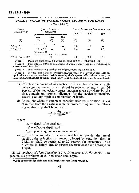
IS :1343-1980
TABLE 5 VALUES OF PARTIAL SAFETY FACTOR y/ FOR LOADS
’ ( Cluu.rc 20.4.2 )
LOAD LIMIT STATE 0~ LIMIT STATES OP SERVICEAI~IL~ COMBINATION ’ COLLAPSE c-----*--.-__~
t--- -*-_-_-# DL LL WL DL LL WL
(1) (2) (3) (4) (5) (6) (7) ~~~~h_~~
DL + LL 1.5 - 1.0 1.0 -
DL + ll’L 1.5 or 0.9 - 1.5 1.0 - 1.0 (ICI Note 2) ~~_~~~*._~~~~~
DL + LL + T1’L I.2 1.0 0.8 0.8
NOTE 1 - DL is the dead load, LL is the live load and WL is the wind load. NOTE 2 -This value of 0.9 is to be considered when stability against overturning or
stress reversal is critical.
NOTE 3 - While considering earthquake effects, substitute EL for WL.
NOTE 4 - For the limit states of serviceability, the values of yr given in this table are applicable for short-term effects. While assessing the long-term effects due to creep, the dead load and that part of the live load likely to be permanent may only be considered.
The elastic moment at any section in a member due to a parti- cular combination of loads shall not be reduced by more than 20 percent of the numerically largest moment given anywhere by the elastic maximum moment diagram for the particular member, covering all appropriate combination of loads. At sections where the moment capacity after redistribution is less than that from the elastic maximum moment diagram, the follow- ing relationship shall be satisfied:
where X, = depth of neutral axis, d = effective depth, and
SM = percentage reduction in moment. e) In structures in which the structural frame provides the lateral
stability, the reduction in moment allowed by condition given in 21.1.1 (c) shall be restricted to 20 percent for structures up to 4 storeys in height and 10 percent for structures over 4 storeys in height.
21.1.2 Annlysis of Slabs Spanning in Two Directions at Right Angles -- In general, the provisions of IS : 456-1978’ shall apply.
*Code of practice for plain and reinforced concrete ( third rctitiun ).
IS : 1343 - 1980
22. LIMIT STATE OF COLLAr&
22.1 Limit State of Collapse : Flexure
22.1.1 Ass~nzptions - Design for the limit state of collapse in flexure shall be based on the assumptions given below:
a) Plane sections normal to the axis remain plane after bending. b) The maximum strain in concrete at the outermost compression
d) ei
f >
fibre is taken as 0.003 5 in bending. The relationship between the comprcssivc stress distribution in concrete and the strain in concrete may be assumed to be rectangle, trapezoid, parabola or any other shape which results in prediction of strength in substantial agreement with the results of tests. An acceptable stress:strain curve is given in Fig. 3. For design purposes, the compressive strength of concrete in the structure shall bc assumed to be 0~67 times the characteristic strength. The partial safety factor ym = 1.5 shall be applied in addition to this.
NOTE - For the stress-strain curve in Fig. 3, the design stress block para- meters for rectangular section are as follows ( see Fig. 4) :
Area of stress block = 0.36f,k . xv Depth of centre of compressive force from the extreme fibre in compres-
sion = 0.42 x,,
where fcr; -= characteristic compressive strength of concrete, and
xx = depth of neutral axis.
The tensile strength of the concrete is ignored. The stresses in bonded prestressing tendons, whether initially tensioned or untensioned, and in additional reinforcement are derived from the representative stress-strain curve for the type of steel used given by the manufacturer or typical curves given in Fig. 5 for prestressing tendons and in IS : 456-1978” for reinforce- ment. For design purposes, the partial safety factor ynr equal to I.15 shall be applied. If tendons are unbonded in post-tensioned members, the stress in the tendons may be obtained from a rigorous analysis or from tests.
22.1.2 Design Forrwtlae - In the absence of an analysis based on the assumptions given in 22.1.1, the moment of resistance of rectangular sec- tions and flanged sections in which the neutral axis lies within the flange may be obtained by the procedure given in Appendix B.
For flanged sections in which the neutral axis lies outside the flange, the moment of resistance shall be determined using assumptions in 22.1.1.
*Code of practice for plain and reinforced concrete ( third revision ).
43
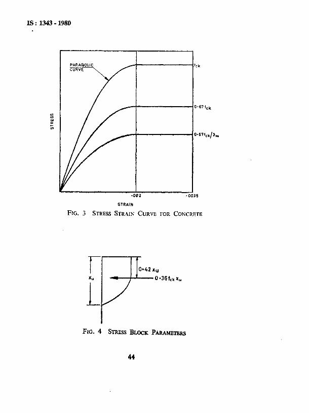
-.
IS : 1343 - 1980
D z ‘j
-002 -0035
STRAIN
FIG. 3 STRESS STRAIN CURVE FOR CONCRETE
FIG. 4 STRESS BLOCK PARAMETERS
44
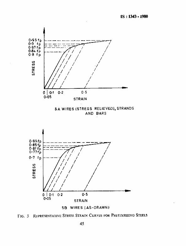
IS:1343-1980
t 0.95 fp 0.9 fp 0.87 f p o.wl f p 0.8 fp
z
ii z
__--_
5A WIRES (STRESS RELIEVED), STRANDS AND BARS
0*2 0.5
STRAIN
58 WIRES (AS-DRAWN)
FIG. 5 REPRESENTATIVE STRESS STRAIN CURVES FOR PRESTRESSING STEELS
45
Is:1343-1980
22.2 Liit State of Collapse :Compression - Prestressed concrete com- pression members in framed structures, where the mean stress in the con- crete section imposed by tendons is less than 25 N/mm2, may be analysed as reinforced concrete compression members in accordance with IS : 456 1978*; in other cases specialist literature may be referred to.
22.3 Limit State of Collapse : Tension,- Tensile strength of the tension members shall be based on the design strength ( 0.87 times characteristic strength of prestressing tendons) and the strength developed by any additional reinforcement. The additional reinforcement may usually be assumed to be acting at its design stress ( 0.87 times characteristic strength of reinforcement ); in special cases it may be necessary to check the stress in the reinforcement using strain compatibility.
22.4 Liiit State of Collapse : Shear - The ultimate shear resistance of the concrete alone, Vo, should be considered at both sections untracked and cracked in flexure, the lesser value taken and, if necessary, shear reinforce- ment provided.
22.4.~ Sections Untracked in Flexure - The ultimate shear resistance of a section untracked in flexure, Vc - VcO, is given by:
V&l = 0.67 bD 2/ft” + 0.8 fi, ft
where b I: breadth of the member which for T, I and L beams
should be replaced by breadth of the rib b,, D = overall depth of the member,
fr - maximum principal tensile stress given by 0.24 t/fTE taken as positive where fGR is the characteristic compressive strength of concrete, and
f&, = compressive stress at centroidal axis due to prestress taken as positive.
In flanged members where the centroidal axis occurs in the flange, the principal tensile stress should be limited to 0*24v’fTat the intersection of the flanged web; in this calculation, 0.8 of the stress due to prestress at this intersection may be used, in calculating V,,.
For a section untracked in flexure and with inclined tendons or verti- cal prestress, the component of prestressing force normal to the longitudi- nal axis of the-member may be added to VcO.
22.4.2 Sections Cracked in Flexure - The ultimate shear resistance of a section cracked in flexure, Vc = Vcr, is given by:
VW = ( 1 - 0.55 fgd f Wd+W; 9 >
*Code of practice for plain and reinforced concrete ( third reuirion ).
46
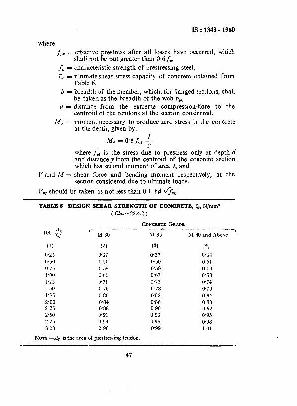
Is : 1343 - 1980
where
.fG = effective prestress after all losses have occurred, which shall not be put greater than 0*6f,,
f, r=1 characteristic strength of prestressing steel, CC = ;uiyt6e shear stress capacity of concrete obtained from
b = breadth) of the member, which, for flanged sections, shall be taken as the breadth of the web E,,
LI = distance from the extreme compression-fibre to the centroid of the tendons at the section considered,
MO = moment necessary to produce zero stress in the concrete at the depth, given by:
MO = 0.8 fpt $- where fDt is the stress due to prestress only at depth d and distance y from the centroid of the concrete section which has second moment of area Z, and
V and M = shear force and bending moment respectively, at the section considered due to ultimate loads.
V,, should be taken as not less than 0.1 bd dfy
TABLE 6 DESIGN SHEAR STRENGTH OF CONCRETE, cc, N/mm2
( Clause 22.4.2 )
‘4P 100 a’
CONCRETE GRADE r----------- ----_-_-~-~
M 30 M 35 M 40 and Above
(1) (2) (3) (4)
0.25 0.37 0.37 0.38 0.50 0.50 0.50 0.51 0.75 0.59 0.59 0.60 1.00 0.66 0.67 0.68 1.25 0’71 0.73 0.74 I.50 0.76 078 0.79 1.75 0.80 082 0.84 2.00 0.84 0.86 0 88 2.25 0.88 0.90 0.92 2.50 0.91 0.93 0.95 2.75 0.94 0.96 0.98 3.00 0.96 @99 1.01
NOTE -A, is the area of pratressing tendon. . .
47
is : 1343 - 1980
The value of Vcr calculated at a particular section may be assumed to be constant for a distance equal to d/2, measured in the direction of increasing moment, from that particular section.
For a section cracked in flexure and with inclined tendons, the com- ponent of prestressing forces normal to the longitudinal axis of the member should be ignored.
22.4.3 Shear Reinforcement
22.4.3.1 When V, the shear force due to the ultimate loads, is less than V,, the shear force which can be carried by the concrete, minimum shear reinforcement should be provided in the form of stirrups such that:
A _z.“,o4 bs, 0.87f;
where A,, = total cross-sectional area of stirrup legs effective in
shear, b = breadth of the ‘member which for T, Z and I, beams
should be taken as the breadth of the rib, b,,
sv -5 stirrup spacing along the length of the member, and f, = characteristic strength of the stirrup reinforcement
which shall not be taken greater than 415 N/mnP.
However, shear reinforcement need not be provided in the following cases:
a) where V is less then 0.5 VC, and
b) in members of minor importance.
22.4.3.2 When V exceeds VC, shear reinforcement shall be provided such that:
A IIv v-v, -- .TU “i_mg,
In rectangular beams, at both corners in the tensile zone, a stirrup should pass around a longitudinal bar, a tendon or a group of tendons t having a diameter not less than the diameter ot the stirrup. The depth dt is then taken as the depth from the extreme compression fibre either to the longitudinal bars or to the centroid of the tendons whichever is greater.
The spacing of stirrups along a member should not exceed 0.75 rl, nor 4 times the web thickness for flanged members. When V exceeds 1.X V,, the maximum spacing should be reduced to O-5 dt. The lateral spacing of the individual legs of the stirrups provided at a cross section should not exceed 0.75 rlt.
48
IS : 1343 - 1980
22.4.4 Maximum Shear Forces - In no circumstances should the shear force V, due to ultimate loads, exceed the appropriate values given in Table 7 multiplied by bd.
TABLE 7 MAXIMUM SHEAR STRESS
Concrete Grade
Maximum Shear Stress,
N/mm%
M 30 M 35
35 3.7
M 40
4.0
M 45
4.3
M 50
4.6
M 55 and over
4.8
22.5 Limit State of Collapse: Torsion
22.5.1 General - In general, where the torsional resistance or stiffness of members has not been taken into account in the analysis of the struc- ture, no specific calculations for torsion will be necessary, adequate control in torsional cracking being provided by the required nominal shear rein- forcement. Where the torsional resistance or stiffness of members is taken into account in the analysis, the members shall be designed for torsion.
22.5.2 Application of Design Rules for Torsion -The design rules laid down in 22.5.3 to 22,5.5 apply to:
a) beams of solid rectangular cross-section ( D > b >,
b) hollow rectangular beams with D > t > 0,‘4, and
c) T-beam and I-beams.
In all these cases the average intensity shall be less than 0.3 fCIC.
22.5.3 Longitudinal Reinforcement
b and with a wall thickness
of prestress in the concrete
22.5.3.1 The longitudinal reinforcement shall be designed to resist an equivalent ultimate bending moment Me, given by:
Me,=M+Mt
where M = applied ultimate bending moment at the cross-section
acting in combination with T,
&=TZ/( 1+?7, the sign of Mt being the same as that
of M, D = overall depth of the beam, and b a breadth of the member which for T and I beams shall be
taken as the breadth of the web, b,.
49
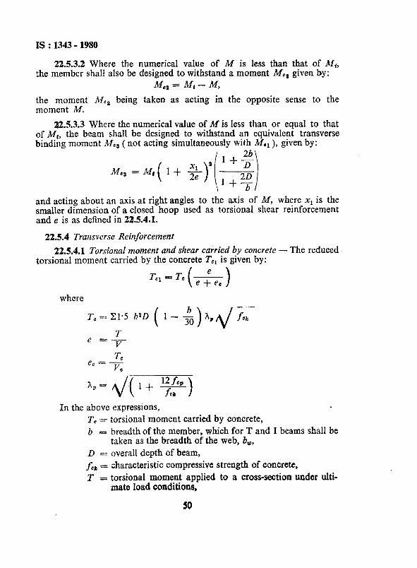
IS :1343-1980
22.5.3.2 Where the numerical value of A4 is less than that of Mt, the member shall also be designed to withstand a moment M,, given by:
MS%= Mt-M,
the moment M,, being taken as acting in the opposite sense to the moment M.
22.5.3.3 Where the numerical value of M is less than or equal to that of M,, the beam shall be designed to withstand an equivalent transverse binding moment Me3 ( not acting simultaneously with MO1 ), given by:
M.,=Mt( 1+ $-f-f) and acting about an axis at right angles to the axis of M, where x1 is the smaller dimension of a closed hoop used as torsional shear reinforcement and e is as defined in 22.5.4.1.
22.5.4 Transverse Reinforcement
22.5.4.1 Torsional moment and shear carried by concrete - The reduced torsional moment carried by the concrete T,, is given by:
Tel -To(*)
where
,Tc==Z1-5 baD (1+,2/c
T e -_ .__ V
A, - d( 12fw 1+ - f% >
In the above expressions, TC = torsional moment carried by concrete,
b== breadth of the member, which for T and I beams shall be taken as the breadth of the web, b,,
D == overall depth of beam, fCk 5= characteristic compressive strength of concrete, T = torsional moment applied to a cross-section under ulti-
mate load conditions,
50
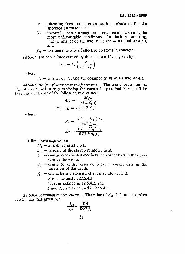
IS : 1343 i 1980
V = shearing force at a cross section calculated for the specified ultimate loads,
V, = theoretical shear strength at a cross section, assuming the most unfavourable conditions for inclined cracking, that is, smaller of VCO and V,, ( see 22.4.1 and 22.4.2 ), and
fC, = average intensity of effective prestress in concrete.
22.5.4.2 The shear force carried by the concrete V,, is given by:
where V, = smaller of V,, and V,, obtained as in 22.4.1 and 22.4.2.
22.5.4.3 Design of transverse reinforcement - The area of cross-section, A,, of the closed stirrup enclosing the corner longitudinal bars shall be taken as the larger of the following two values:
A M& So =
__---- I.5 b,d, f,
and A aq=-~v+2AT
where A = (V-Vc,)sv
” 0*87f, dl
AT =I ( T- Tel ) so 0.87 b,d, f,
In the above expressions, Mt = as defined in 22.5.3.1, sz, = spacing of the stirrup reinforcement, b, = centre to centre distance between corner bars in the direc-
tion of the width, d1 = centre to centre distance between corner bars in the
direction of the depth, f, = characteristic strength of shear reinforcement,
V is as defined in 22.5.4.1, VCl is as defined in 22.5.4.2, and T and T,, are as defined in 22.5.4.1.
22.5.4.4 Minimum reinforcement -- The value of A,, shall not be taken lesser than that given by:
A 0.4 1o = 0.87 fi b a0
51
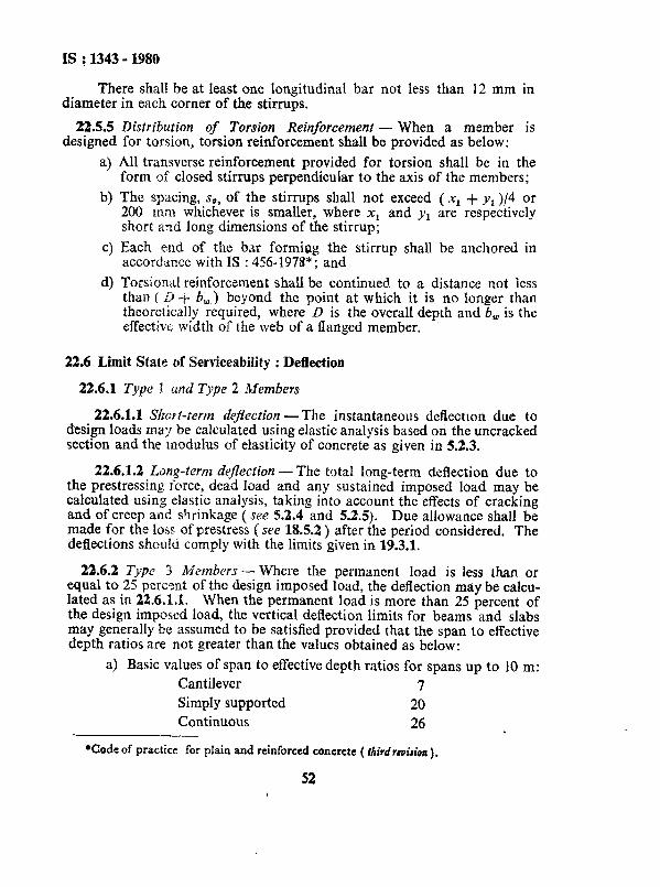
IS : 1343 - 1980
There shall be at least one longitudinal bar not less than 12 mm in diameter in each corner of the stirrups.
22.55 Distribution of Torsion Reinforcement - When a member is designed for torsion, torsion reinforcement shall be provided as below:
a) All transverse reinforcement provided for torsion shall be in the form of closed stirrups perpendicular to the axis of the members;
b) The spacing, s., of the stirrups shall not exceed ( x1 + y, )/4 or 200 mm whichever is smaller, where x1 and y1 are respectively short and long dimensions of the stirrup;
c) Each end of the bar forming the stirrup shall be anchored in accordmce with IS : 456-1978”; and,
d) Torsional reinforcement shall be continued to a distance not less than I D + b,) beyond the point at which it is no longer than theoretically required, where D is the overall depth and b, is the effect& width of the web of a flanged member.
22.6 Limit State nf Serviceability : Deflection
22.6.1 Type I and Type 2 Members
22.6.1.1 5% f-ierm deflection - The instantaneous deflectron due to design loads ma.;! be calculated using elastic analysis based on the untracked section and the modulus of elasticity of concrete as given in 5.2.3.
22.6.1.2 Long-term defection - The total long-term deflection due to the prestressing force, dead load and any sustained imposed load may be calculated using elastic analysis, taking into account the effects of cracking and of creep and shrinkage ( see 5.2.4 and 5.2.5). Due allowance shall be made for the loss. of prestress ( see 18.5.2 ) after the period considered. The deflections shculd comply with the limits given in 19.3.1.
22.6.2 Type 3 Mrmber.r - Where the permanent load is less than or equal to 25 percent of the design imposed load, the deflection may be calcu- lated as in 22.6.1.1. When the permanent load is more than 25 percent of the design imposed load, the vertical deflection limits for beams and slabs may generally be assumed to be satisfied provided that the span to effective depth ratios are not greater than the values obtained as below:
a) Basic values of span to effective depth ratios for spans up to 10 m: Cantilever 7 Simply supported 20 Continuous 26
*Code of practice for plain and reinforced concrete ( fhirdreutiion ).
52
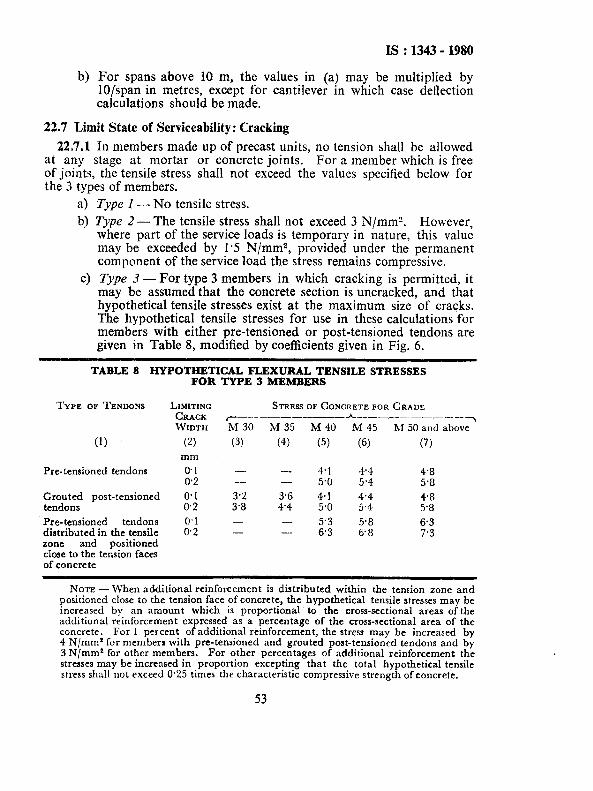
b)
IS : 1343 - 1980
For spans above 10 m, the values in (a) may be multiplied by IO/span in metres, except for cantilever in which case deflection calculations should be made.
22.7 Limit State of Serviceability: Cracking
22.7.1 In members made up of precast units, no tension shall be allowed at any stage at mortar or concrete joints. For a member which is free of joints, the tensile stress shall not exceed the values specified below for the 3 types of members.
a) Type I - No tensile stress. b) Type 2 -The tensile stress shall not exceed 3 N/mm?. However,
where part of the service loads is temporary in nature, this value may be exceeded by I.5 N/mm2, provided under the permanent component of the service load the stress remains compressive.
c) Type 3 - For type 3 members in which cracking is permitted, it may be assumed that the concrete section is untracked, and that hypothetical tensile stresses exist at the maximum size of cracks. The hypothetical tensile stresses for use in these calculations for members with either pre-tensioned or post-tensioned tendons are given in Table 8, modified by coefficients given in Fig. 6.
TABLE 8 HYPOTHETICAL FLEXURAL TENSILE STRESSES FOR TYPE 3 MEMBERS
TYPE OF TENDONS LIMITING STRESS OF CONCRETE FOR GRADE CRACK r--- -_------- h__-_______-~
WIDTH M 30 M 35 M 40 M 45 hl50and above
(1) (2) (3) (4) (5) (6) (7) mm
Pre-tensioned tendons 0.1 - - 4.1 @2 -- - 5.0 ;:; ;:;
“,zd;;f post-tensioned 0”:; 33:;
4.1 4.4 ,;:4” 5.0
4.8 5.4 5.8
Pre-tensioned tendons 0.1 - - 6.3 distributed in the tensile 0’2 - - 2:; 2:; 7.3 ZO*e and positioned close to the tension faces of concrete
NOTE -When additional reinforcement is distributed within the tension zone and positioned close to the tension face of concrete, the hypothetical tensile stresses may be increased bv an amount which is proportional to the cross-sectional areas of the additional r&forcement expressed as a percentage of the cross-sectional area of the concrete. For 1 percent of additional reinforcement, the stress may be increased by 4 N/mm” for members with pre-tensioned and grouted post-tensioned tendons and by 3 N/mm* for other members. For other percentages of additional reinforcement the stresses may be increased in proportion excepting that the total hypothetical tensile stress shall not exceed 0.25 times the characteristic compressive strength ofconcrete.
53
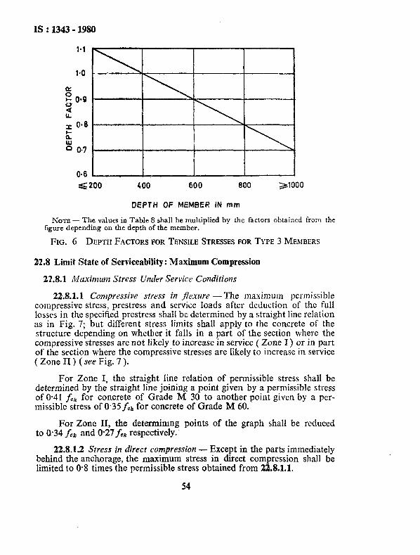
SE00 200 600 600 >,lOOO
DEPTH OF MEMBER IN mm
NOTE -The values in Table 8 shall be multiplied by the factors obtained from the figure depending on the depth of the member.
FIG. 6 DEPTH FACTORS FOR TENSILE STRESSES FOR TYPE 3 MEMBERS
22.8 Limit State of Serviceability: Maximum Compression
22.8.1 Maximunn Stress Under Service Conditions
22.8.1.1 Compressive stress in .flexure -The maximum permissible compressive stress, prestress and service loads after deduction of the full losses in the specified prestress shall bc determined by a straight line relation as in Fig. 7; but different stress limits shall apply to the concrete of the structure depending on whether it falls in a part of the section where the compressive stresses are not likely to increase in service ( Zone I ) or in part of the section where the compressive stresses are likely to increase in service ( Zone II ) ( see Fig. 7 ).
For Zone I, the straight line relation of permissible stress shall be determined by the straight line joining a point given by a permissible stress of 0.41 fck for concrete of Grade M 30 to another point given by a per- missible stress of 0.35& for concrete of Grade M 60.
For Zone II, the determining points of the graph shall be reduced to 0.34 fcb and 0.27 fck respectively..
22X1.2 Stress in direct compression - Except in the parts immediately behind the anchorage, the maximum stress in direct compression shall be limited to 0.8 times the permissible stress obtained from 22.8.1.1.
54
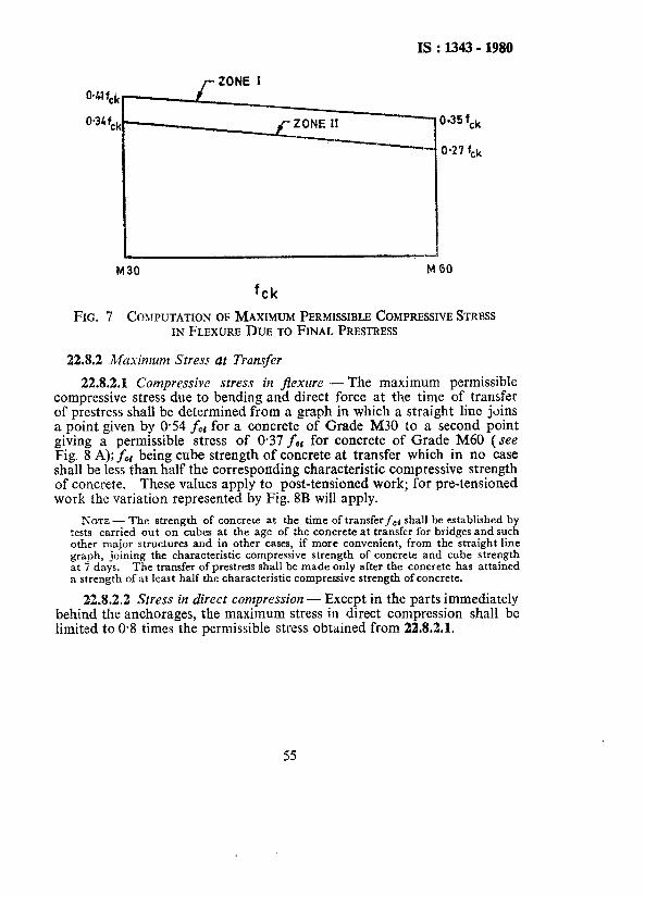
IS : 1343 - 1980
/-ZONE I
O-35$,
0.27 f&
M30
fck
MGO
FIG. 7 CO~IPUTATION OF MAXIMUM PERMISSIBLE COMPRESSIVE STRESS IN FLEXURE DUE TO FINAL PRESTRESS
22.8.2 Mrrsimum Stres,c dt Transfer
22.8.2.1 Compressive swess in jexrtre - The maximum permissible compressive stress due to bending and direct force at the time of transfer of prestress shall be determined from a graph in which a straight line joins a point given by O-54 fcs for a concrete of Grade M30 to a second point giving a permissible stress of O-37 fbl for concrete of Grade M60 (see Fig. 8 A); fci being cube strength of concrete at transfer which in no case shall be less than half the corresponding characteristic compressive strength of concrete. These values apply to post-tensioned work; for pre-tensioned work the variation represented by Fig. 8B will apply.
NOTE - The strength of concrete at the time of transferf,i shall be established by tests carried out on cubes at the age of the concrete at transfer for bridges and such other major structures and in other cases, if more convenient, from the straight line granh, joining the characteristic compressive strength of concrete and cube strength at 5 days. The transfer of prestress shall be made only after the concrete has attained a strength of at least half the characteristic compressive strength of concrete.
22.8.2.2 Stress in direct compression - Except in the parts immediately behind the anchorages, the maximum stress in direct compression shall be limited to 0.8 times the permissible stress obtained from 22.8.2.1.
55
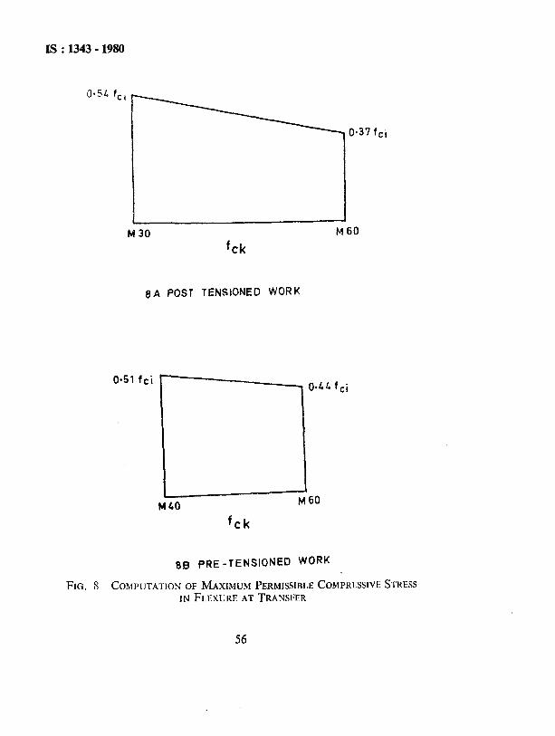
IS : 1343 - 1980
o*sc f,,
fck
M60
8A POST TENSIONED WORK
4 c M&O M 60
fck
69 PRE -TENSIONED WORK
FIG. 8 COMPUTATION OF MAXIMUM PERMKSIBLE COMPIWSIVE &RESS IN FLIXJRE AT TRANSFER
56
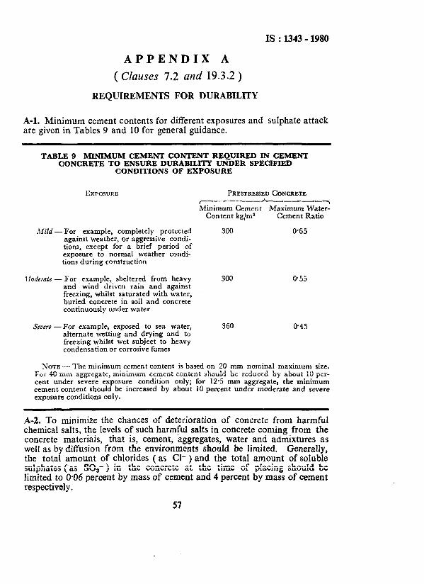
IS : 1343 - 1980
APPENDIX A
( Clauses 7.2 and 19.3.2 )
REQUIREMENTS FOR DURABILITY
A-l. Minimum cement contents for different exposures and sulphate attack are given in Tables 9 and 10 for general guidance.
TABLE 9 MINIMUM CEMENT CONTENT REQUIRED IN CEMENT CONCRETE TO ENSURE DURABILITY UNDER SPECIFIED
CONDITIONS OF EXPOSURE
l$XPOSURE PRESTRESSED CONCRETE (-----__* ----7 Minimum Cement Maximum Water-
Content kg/m3 Cement Ratio
Mild - For example, completely protected 300 0.65 against weather, or aggressive condi- tions, except for a brief period of exposure to normal weather condi- tions during construction
1 federate - For example, sheltered from heavy and wind driven rain and against freezing, whilst saturated with water, buried concrete in soil and concrete continuously under water
300 055
Severe -For example, exposed to sea water, alternate wetting and drying and to freezing whilst wet subject to heavy condensation or corrosive fumes
360 0.45
NOTE - The minimum cement content is based on 20 mm nominal maximum size. For 40 mm aggregate, minimum cement content should be reduced by about 10 per- cent under severe exposure condition only; for 12.5 mm aggregate, the minimum cement content should be increased by about IO percent under moderate and severe exposure conditions only.
A-2. To minimize the chances of deterioration of concrete from harmful chemical salts, the levels of such harmful salts in concrete coming from the concrete materials, that is, cement, aggregates, water and admixtures as well as by dXusion from the environments should be limited. Generally, the total amount of chlorides ( as Cl- ) and the total amount of soluble sulphates (as SO,- ) in the concrete at the time of placing should be limited to 0.06 percent by mass of cement and 4 percent by mass of cement respectively.
57
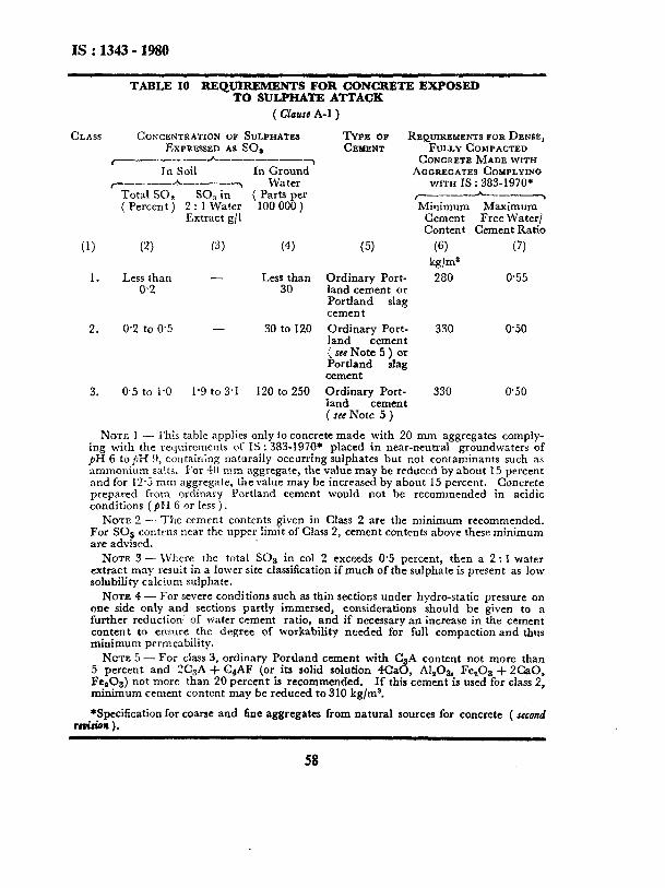
I. __._..-... -
IS : 1343 - 1980
TABLE 10 REQUIREMENTS FOR CONCRETE EXPOSED TO SULPHATE ATTACK
( Clause A-l )
CLASS CONCENTRATION OF SULPHATES TYPE OF REQUIREMENTS FOR DENSE, l?‘XPREssED AS SO* CEMENT FULLY COMPACTED
f----- _h-----~ CONCRETE MADE WITH
Jn Soil In Ground AGGREG.~TES COMPLYIN r_-_-*-__7 Water WITH 1s : 383-1970*
Total SC9 s SO, in ( Parts per ~~~~h~~_ ( Percent) 2 : 1 Water 100 000) Minimum Maximum
Extract g/l Cement Free Water/ Content Cement Ratio
(1) (2) (3) (4) (5) (6) (7)
kg/m’ 1. Less than - Less than Ordinary Port- 280 0’55
0~2 30 land cement or Portland slag cement
2. 0.2 to 0.5 - 30 to 120 C)~nary Port- 330 0.50 cement
( see Note 5 ) or Portland slag cement
3. 0.5 to 1.0 l-9 to 3.1 120 to 250 Ordinary Port- 330 0.50 land cement ( see Note 5 )
NOTE 1 - ‘l‘his table applies only to concrete made with 20 mm aggregates comply- ing with the requirements of IS : 383-1970+ placed in near-neutral groundwaters of pH 6 t0,jI-I 9, containing naturally occurring sulphates but not contaminants such as ammomum s&s. For 4(1 mm aggregate, the value may be reduced by about 15 percent and for 32.5 mm aggregate, the value may be increased by about 15 percent. Concrete prepared from ordinary Portland cement would not be recommended in acidic condition% (pIi 6 or less ) .
NOTE 2 --The cement contents given in Class 2 are the minimum recommended. For SOS contpns near the upper limit of Class 2, cement contents above these minimum are advised.
NOTE 3 - Where the total SOS in co1 2 exceeds 0.5 percent, then a 2: 1 water extract may result in a lower site classification if much of the sulphate is present as low solubility calcium sulphate.
NOTE 4 - For severe conditions such as thin sections under hydro-static pressure on one side only and sections partly immersed, considerations should be given to a further reduction of water cement ratio, and if necessary an increase in the cement content to ensure the degree of workability needed for full compaction and thus minimum permeability.
NCTE 5 - For class 3, ordinary Portland cement with CIA content not more than 5 percent and ?&A + C4AF (or its solid solution 4Ca0, AlsOa, Fe,03 + 2Ca0, Fe,Os) not more than 20 percent is recommended. If this cement is used for class 2, minimum cement content may be reduced to 310 kg/ma.
*Specification for coarse and fine aggregates from natural sources for concrete ( second r&n ).
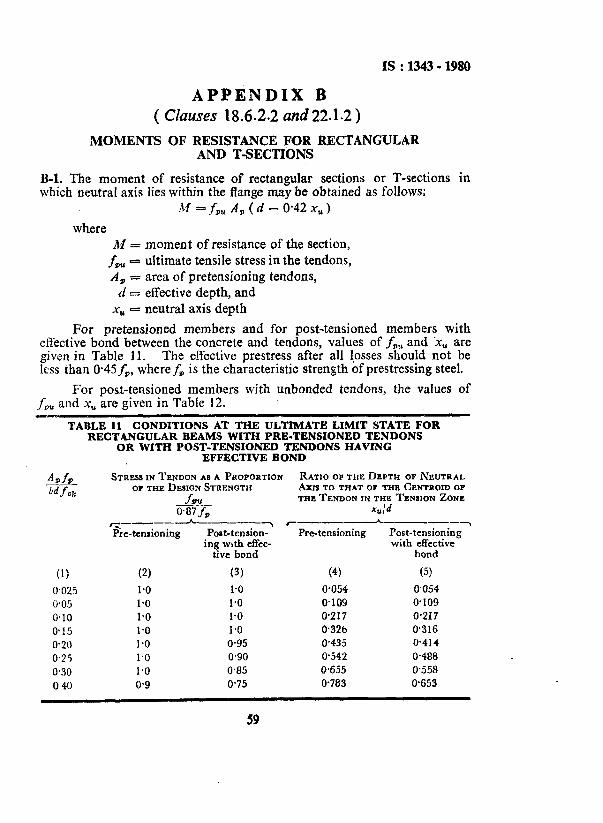
1s : 1343 - 1980
APPENDIX B ( Clauses 18.6.2.2 and 22.1.2)
MOMENTS OF RESISTANCE FOR RECTANGULAR AND T-SECTIONS
B-l. The moment of resistance of rectangular sections or T-sections in which neutral axis lies within the flange may be obtained as follows;
112 -f,” A, (n - 0.42~“)
where M = moment of resistance of the section,
jY,, = ultimate tensile stress in the tendons, A, = area of pretensioning tendons,
d = effective depth, and x, = neutral axis depth
For pretensioned members and for post-tensioned members with eft’ective bond between the concrete and tendons, values of f,,, and ‘x, are given in Table 11. The effective prestress after all 1,osses should not be less than 0.45 f,, where f, is the characteristic strength of prestressing steel.
For post-tensioned members with unbonded tendons, the values of f," and x, are given in Table 12.
TABLE 11 CONDITIONS AT THE ULTIMATE LIMIT STATE FOR RECTANGULAR BEAMS WITH PRE-TENSIONED TENDONS
OR WITH POST-TENSIONED TENDONS HAVING EFFECTIVE BOND
A9fD bdf ck
(1)
0.025 0.05 0.10 0.15 0.20
0.25 0.30 0.40
STRESS IN TENDON AS A PROPORTION RATIO OF THE DEPTH OF NEUTRAL OR THE DESION STRENQTW AXIS TO THAT op THE CENTROID OF
f It>- THE TENDON IN THE TSNIION ZONE 0.87 fD x,/d
#-_-----h------, -. r--_-__~ Pre-tensioning Pont-tenrion- Pre-tensioning Post-tensioning
ing w1t.h effec- with effective tive bond bond
(2) (3) (4) (5)
1.0 1.0 0.054 0,054 1.0 1.0 0.109 0109 1.0 1.0 0.217 0*2I 7 I.0 1.0 0.326 0.316 I.0 0.95 0.435 0.414 1.0 0.90 0.542 0.488 1.0 0‘85 0.655 0.558 0.9 0.75 0.783 0.653
59
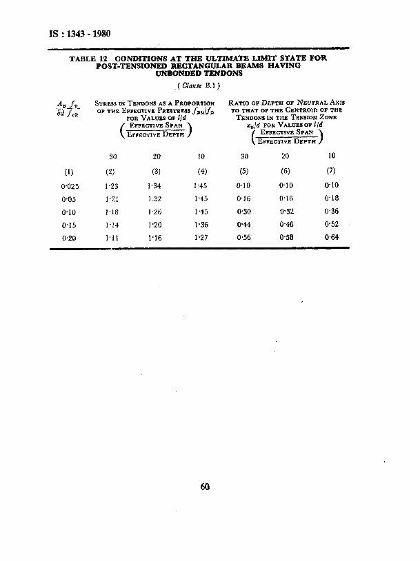
Lr- . . . ..l~“_ . . l ._-_.._.._.__
IS : 1343 - 1980
TABLE 12 CONDITIONS AT THE ULTIMATE LIMIT STATE FOR POST-TENSIONED RECTANGULAR BEAMS HAVING
UNBONDED TENDONS
( lXause B-1 )
%L!k bd fck
(1)
0.025
0.05
0.10
0.15
o-20
STRESS IN TENDONS AS A PROPORTION RATIO OF DEPTH OF NEUTRAL Axrs OF THE EPPECTIV~ PRESTRES~ fJf2 TO THAT OF THE CENTROID OF THE
FORVALUEiOF l/d TENDONS IN THE TENSION ZONE EFFBCXIVE SPAN x,/d FOR VALUES OF l/d
EFFECTIVE DE~H EFFECTIVE SPAN EFFECTIVE DEPTH >
30 20 10 30 20 10
(2! (3) (4) (5) (6) (7)
1.23 l-34 1’45 O-10 @IO 010
1.21 1.32 I*45 0.16 0.16 0.18
1.18 1.26 1.45 0.30 0% 0.36
l-14 1.20 l-36 0.44 0.46 O-52
1.11 l-16 1.27 O-56 0.58 0.64
60
L - . . _. . . ___._
IS:1343-1980
( Continuedfrom page 2 )
Prestrcssed Concrete Subcommittee, BDC 2 : 8
Members Representing ADDITIONAL DIRECTOR, STANDARDS Research Designs & Standards Organization
(B & S) (Ministry of Railways ), Lucknow DEPU~ DIRECTOR, STANDARDS
( B & S ) ( Afternate ) SHRI C. R. ALIMCHANDANX Stup Consultants Ltd, Bombay
SHRI M. C. TANDON ( Alfemafe ) DIRECTOR ( CANALS ) Central Water Commission, New Delhi
DEPUTY DIRECTOR ( CANALS ) ( Alternate ) SHRI D. T. GROVER Roads Wing, Ministry of Shipping and Transport
SHRI A. S. BWINO~ ( Alwnate ) SHRI S. T. KHAN Killick Nixon Ltd, Bombay
SHRI S. M. BILCRAMI ( Alternate ) SHR~ G. K. MAJUMDAR Hindustan Prefab Ltd, New Delhi
SHRI H. S. PASRICHA ( Alternate ) SHRI D. B. NAUC
SHR~ SUCHA SINGH ( Alternate ) Engineer-in-Chief’s Branch, Army Headquarters
SHRI K. K. NAMBIAR In personal capacity ( ‘Ramanalaya’ II First Crescent Park Road, Gandhi .Nagar, Adyar, Madras )
SHRI B. K. PANTHAKY SHRI V. S. PARAMFSWARAN
The Hindustan.Construction Co Ltd, Bombay Struct~~~~pneenng Research Centre ( CSIR ),
SHRI A. S. P. RAO ( Alternate ) DR A. V. R. RAO National Buildings Organization, New Delhi
SHRI K. S. SRINIVASAN ( Al&male) SHRI T. N. S. RAO Gammon India Ltd. Bombay
SHRI S. R. PINHEIRO ( Aknalc ) SUPERINTZNDIN~ SURVEYOR OF Central Public Works Department, New Delhi
\VoRKS ( NDZ ) SURVEYOR OF WORKS III I NDZ 1
( AlternaQ ) SHRI B. T. UNWALLA The Concrete Association of India, Bombay
SHRI N. C. DUQGAL ( Alternate ) DR H. C. VISVESVARAYA Cement Research Institute of India, New Delhi
SHRI S. SUBRAMANIAN ( Alternate )
Panel for Revision of Concrete Codes, BDC 2 : 2/2 : 8/P : 1
Conuener
DR H. C. VI~VE~~ARAYA
Members DR IQBAL ALI DR A. K. MULLICK Snnr P. PADMANABHAN
( OFFICER ON SPEClAL Dun ) SHRI V. S. PARAMESWARAN
SHRI V. K. GHANEKAR
Cement Research Institute of India, New Delhi
Engineering Research Laboratories, Hyderabad Cement Research Institute of India, New Delhi Indian Standards Institution
Struc~~;~&neering Research Ccn tre ( CSIR ),
Stru~;r~~enginaring Research Centre ( CSIR ),
( Continued on page 62 )
61
IS :1343-1980
Members R~pW&lg
SHRI S.R. PINHEIRO DRG.P. SAHA (Altcrnak)
Gammon India Ltd, Bombay
SHRI D. AJITHA SIMHA Indian Standarda Institution SHRI C.N. SRINIVASAN M/s C. R. Narayana Rao, Madras SHRI S. SUBRAMAN~AN Cement Research Institute of India, New Delhi SHRI B.T. UNWALLA
SHRI Y. K. MEHTA ( Alfcrnata ) The Concrete Association of India, Bombay
Working Group for Revision of IS : 456 and IS : 1343
Cotwencr
SXRI D. AJITHA SIMW
Members
SHRI v. K. G HANERAR
Indian Standards Institution
Stru;~;ct~enginccring Research Centre ( CSIR ),
SHRI M.N. NEELAKANDHAN Indian Standards Institution SHRI P. PADMANABHAN Indian Standards Institution ; t,~y;ammS~S;;~~ DUTY ) H. Cement Research Institute of India, New Delhi
62
BUREAU OF INDIAN STANDARDS
Headquarters: Manak Bhavan, 9 Bahadur Shah Zafar Marg, NEW DELHI 110002 Telephones: 323 0131, 323 3375, 323 9402 Fax : 91 11 3234062, 91 11 3239399,91 11 3239382
Telegrams : Manaksanstha (Common to all Offices)
Central Laboratory: Telephone
Plot No. 20/9, Site IV, Sahibabad Industrial Area, Sahibabad 201010 8-77 00 32
Regional Offices:
Central : Manak Bhavan, 9 Bahadur Shah Zafar Marg, NEW DELHI 110002 32376 17
“Eastern : 1114 CIT Scheme VII M, V.I.P. Road, Maniktola, CALCUTTA 700054 337 86 62
Northern : SC0 335-336, Sector 34-A, CHANDIGARH 160022 60 38 43
Southern : C.I.T. Campus, IV Cross Road, CHENNA! 600113 23523 15
TWestern : Manakalaya, E9, Behind Marol Telephone Exchange, Andheri (East), 832 92 95 MUMBAI 400093
Branch Offices:
‘Pushpak’, Nurmohamed Shaikh Marg, Khanpur, AHMEDABAD 38CrOOl 550 13 48
-$ Peenya Industrial Area, 1st Stage, Bangalore-Tumkur Road, 839 49 55 BANGALORE 560058
Gangotri Complex, 5th Floor, Bhadbhada Road, T.T. Nagar, BHOPAL 462003 55 40 21
Plot No. 62-63, Unit VI, Ganga Nagar, BHUBANESHWAR 751001 40 36 27
Kalaikathir Buildings, 670 Avinashi Road, COIMBATORE 641037 21 01 41
Plot No. 43, Sector 16 A, Mathura Road, FARIDABAD 121001 8-28 88 01
Savitri Complex,.116 G.T. Road, GHAZIABAD 201001 8-71 19 96
53/5 Ward No. 29, R.G. Barua Road, 5th By-lane, GUWAHATI 781003 54 11 37
5&6C, L.N. Gupta Marg, Nampally Station Road, HYDERABAD 5OCOtIl 20 10 83
E-52, Chitaranjan Marg, C-Scheme, JAIPUR 302001 37 29 25
117/418,B, Sarvodaya Nagar, KANPUR 208005 21 68 76
Seth Bhawan, 2nd Floor, Behind Leela Cinema, Naval Kishore Road, 23 89 23 LUCKNOW 226001
NIT Building, Second Floor, Gokulpat Market, NAGPUR 440010 52 51 71
Patlioutra Industrial Estate, PATNA 800013 26 23 05
Institution of Engineers (India) Building 1332 Shivaji Nagar, PUNE 411005 32 36 35
T.C. No. 14/1421, University P.O. Palayam, THIRUVANANTHAPURAM 695034 621 17
*Sales Office is at 5 Chowringhee Approach, P.O. Princep Street, CALCUTTA 700072
TSales Office is at Novelty Chambers, Grant Road, MUMBAI 400007
$Sales Office is at ‘F’ Block, Unity Building, Narashimaraja Square, BANGALORE 560002
271085
309 65 28
222 39 71
Prinled at Simco Printing Press, Delhi
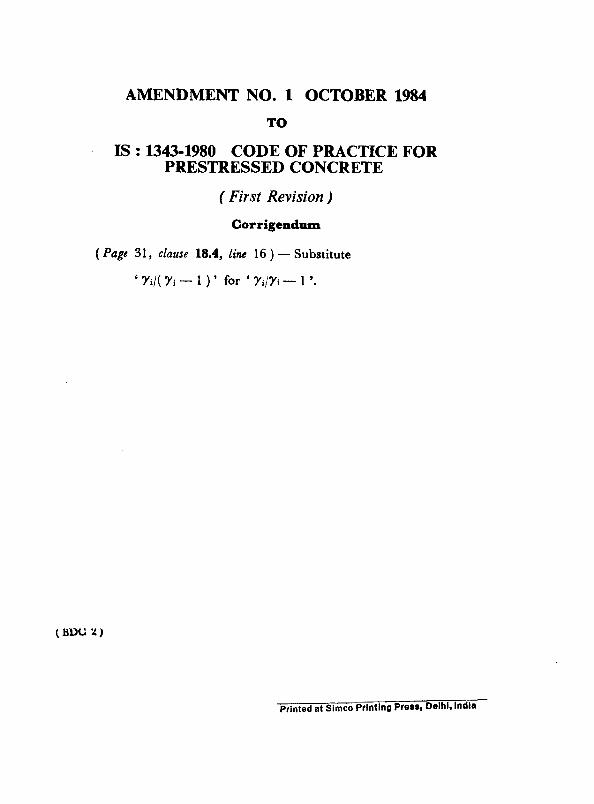
.- -.- .,.
AMENDMENT NO. 1 OCTOBER 1984
TO
IS : 1343-1980 CODE OF PRACTICE FOR PRESTRESSED CONCRETE
( First Revision )
corrigendum
(Page 31, clause 18.4, line 16 ) - Substitute
’ Yi/( Yi - 1 )’ for ‘ Yi/Yi - I ‘.
Printed at Simco Printing Press, Delhi, India