Embed Size (px)
Citation preview

Disclosure to Promote the Right To Information
Whereas the Parliament of India has set out to provide a practical regime of right to information for citizens to secure access to information under the control of public authorities, in order to promote transparency and accountability in the working of every public authority, and whereas the attached publication of the Bureau of Indian Standards is of particular interest to the public, particularly disadvantaged communities and those engaged in the pursuit of education and knowledge, the attached public safety standard is made available to promote the timely dissemination of this information in an accurate manner to the public.
इंटरनेट मानक
“!ान $ एक न' भारत का +नम-ण”Satyanarayan Gangaram Pitroda
“Invent a New India Using Knowledge”
“प0रा1 को छोड न' 5 तरफ”Jawaharlal Nehru
“Step Out From the Old to the New”
“जान1 का अ+धकार, जी1 का अ+धकार”Mazdoor Kisan Shakti Sangathan
“The Right to Information, The Right to Live”
“!ान एक ऐसा खजाना > जो कभी च0राया नहB जा सकता है”Bhartṛhari—Nītiśatakam
“Knowledge is such a treasure which cannot be stolen”
“Invent a New India Using Knowledge”
है”ह”ह
IS 10460 (1983): Functional requirements for small foamtender for fire brigade use [CED 22: Fire Fighting]


© BIS 2005
B U R E A U O F I N D I A N S T A N D A R D SMANAK BHAVAN, 9 BAHADUR SHAH ZAFAR MARG
NEW DELHI 110002
IS : 10460 - 1983(Reaffirmed 2000)
Edition 1.1(1988-11)
Price Group 5
Indian StandardFUNCTIONAL REQUIREMENTS FOR
SMALL FOAM TENDER FORFIRE BRIGADE USE
(Incorporating Amendment No. 1)
UDC 614.846.63 : 614.842.615
IS : 10460 - 1983
© BIS 2005
BUREAU OF INDIAN STANDARDS
This publication is protected under the Indian Copyright Act (XIV of 1957) andreproduction in whole or in part by any means except with written permission of thepublisher shall be deemed to be an infringement of copyright under the said Act.
Indian StandardFUNCTIONAL REQUIREMENTS FOR
SMALL FOAM TENDER FORFIRE BRIGADE USE
Fire Fighting Sectional Committee, BDC 22Chairman Representing
SHRI G. B. MENON Ministry of Home Affairs
Members
SHRI MAHESH C. AGARWAL Brijbasi Udyog, MathuraSHRI P. S. BANERJEE ( Alternate )
SHRI S. R. BANSAL Steel Authority of India (Bokaro Steel Plant), BokaroSHRI A. CHATTERJEE Tariff Advisory Committee, Bombay
SHRI F. B. SANJANA ( Alternate )DEPUTY INSPECTOR GENERAL (RPSE)
Ministry of Railways
ASSISTANT SECURITY OFFICER(F I R E) (NORTHERNRAILWAY) ( Alternate )
SHRI V. P. DEWAN Ministry of Defence (DGI)LT-COL V. R. BANAHATI ( Alternate )
SHRI R. R. DHOBLEY Bhabha Atomic Research Centre, BombayDIRECTOR Home Department (Fire Service), Government of
Tamil Nadu, MadrasDEPUTY DIRECTOR ( Alternate )
DIRECTOR (FIRE SERVICES) Home (Police) Department, Government of AndhraPradesh, Hyderabad
DEPUTY DIRECTOR (FIRE SERVICES) ( Alternate )
SHRI G. N. GIDWANI Directorate General of Supplies and Disposals, NewDelhi
SHRI D. N. PANDIT ( Alternate )SHRI A. K. GUPTA Central Building Research Institute (CSIR), RoorkeeSHRI K. K. DAS GUPTA West Bengal Fire Services, CalcuttaSHRI J. S. JAMSHEDJI Steelage Industries Limited (Minimax Division),
BombaySHRI C. GHANARAJ ( Alternate )
( Continued on page 2 )
IS : 10460 - 1983
2
( Continued from page 1 )Members Representing
SHRI S. N. KUNDU Fire and Safety Appliances Co, CalcuttaMANAGING DIRECTOR Avon Services (P & A) Private Ltd, Bombay
TECHNICAL EXECUTIVE ( Alternate )SHRI B. R. MEHTA The Institution of Fire Engineers (India), New Delhi
SHRI A. N. AHLUWALIA ( Alternate )COL S. A. MOHILE Ministry of Defence (R & D)
SHRI A. K. SURI ( Alternate )SHRI M. MUKHERJI Steel Authority of India (Rourkela Steel Plant),
RourkelaSHRI C. D. SHARMA ( Alternate )
SHRI V. B. NIKAM Municipal Corporation of Greater Bombay (BombayFire Brigade), Bombay
SHRI P. N. PANCHAL Central Industrial Security Force (Ministry of HomeAffairs), New Delhi
SHRI P. L. SEBASTIN Oil & Natural Gas Commission, Dehra DunSHRI V. V. KIMMATKAR ( Alternate )
SHRI P. H. SETHNA Kooverji Devshi and Co Pvt Ltd, BombaySHRI N. T. PANJWANI ( Alternate )
SHRI D. K. SIRKAR Synthetics and Chemicals Ltd, BareillySHRI CHANDRAKANT M. SHAH Zenith Fire Services, Bombay
SHRI M. H. SHAH ( Alternate )SHRI J. V. SHAH Newage Industries, Surendranagar
SHRI B. J. SHAH ( Alternate )SHRI S. S. L. SHARMA Municipal Corporation of Delhi (Delhi Fire Services),
DelhiSHRI R. K. BHARDWAJ ( Alternate )
SHRI TARIT SUR Sur Enamel & Stamping Works Pvt Ltd, CalcuttaSHRI S. SUR ( Alternate )
SHRI SUSHIL KUMAR Directorate General of Technical Development,New Delhi
SHRI S. VENKASWAMY Directorate General of Civil Aviation New DelhiSHRI B. V. WAGLE Urban Development and Public Health Department,
BombaySHRI V. H. MADKAIKAR ( Alternate )
SHRI G. RAMAN,Director (Civ Engg)
Director General, ISI ( Ex-officio Member )
SecretarySHRI K. M. MATHUR
Deputy Director (Civ Engg), ISI
Fire Fighting Units Subcommittee, BDC 22 : 3Convener
SHRI P. N. GHOSH The Institution of Fire Engineers (India), New DelhiMembers
SHRI A. CHATTOPADHYAY ( Alternate toShri P. N. Ghosh )
SHRI V. P. DEWAN Ministry of Defence (DGI)LT-COL V. R. BANAHATI ( Alternate )
( Continued on page 19 )
IS : 10460 - 1983
3
Indian StandardFUNCTIONAL REQUIREMENTS FOR
SMALL FOAM TENDER FORFIRE BRIGADE USE
0. F O R E W O R D
0.1 This Indian Standard was adopted by the Indian StandardsInstitution on 28 February 1983, after the draft finalized by the FireFighting Sectional Committee had been approved by the CivilEngineering Division Council.
0.2 A number of Indian Standards on fire fighting appliances ofdifferent capacities using various media for use in towns and ruralareas are available. There are also standards covering large capacityfire fighting appliances for aircraft-crash fire fighting, built on specialchassis which are being imported as the type of chassis required is notavailable in this country. This standard is intended to cover the use ofindigenously produced chassis.
0.3 The appliance conforming to this standard is intended primarilyfor use in petro-chemical complexes, oil refineries or storages andheavy industries where large quantities of oils or petroleum productsare being used as fuel for lubrication purposes.
0.4 The provision of monitor on the top of appliance has been made tomake the appliance more versatile and reliable in attacking firessafely from a distance. Hand lines have their own advantages inindustrial complexes to deal with spillage and running fires and alsoat places which cannot be attacked by the monitor.
0.5 Though the appliance is basically for fighting fires with foam, yetkeeping in view the effectiveness of dry powder on fires involvingelectrical and other connected equipments used in handling andprocessing flammable oils, the provision of dry powder system has beenmade in the standard as supplementary fire extinguishing medium.
0.6 A list of accessories and equipment which do not form part of thisappliance and most of which are normally required to assist inoperation of the appliance is given in Appendix B for information andguidance. The appliance shall also conform to statutory rules in regardto height clearance framed by Transport Authority.
0.7 This edition 1.1 incorporates Amendment No. 1 (November 1988).
IS : 10460 - 1983
4
Side bar indicates modification of the text as the result ofincorporation of the amendment.
0.8 For the purpose of deciding whether a particular requirement of thisstandard is complied with, the final value, observed or calculated,expressing the result of a test, shall be rounded off in accordance withIS : 2-1960*. The number of significant places retained in the rounded offvalue should be the same as that of the specified value in this standard.
1. SCOPE
1.1 This standard lays down the requirements regarding material,design and construction, workmanship and finish, accessories andequipment of small foam tender for fire brigade use.
2. GENERAL REQUIREMENTS
2.1 The appliance shall incorporate a fire pump of 1 800 l/min capacity,a water tank of 1 800 l or 2 000 l capacity, a foam tank of 500 l capacityand connected equipment for foam production and also supplementaryextinguishing agent ( see Appendices A and B ).
2.2 The foam tender shall be fabricated in a manner so as to conform tothe following characteristics:
*Rules for rounding off numerical values ( revised ).
a) Gross vehicle weight not less than 11 000 kg including crew,water and equipment.
b) Maximum speed on level road, fully laden, 72 km/h.c) Acceleration from a standing start through the gears, fully
laden, 64 km/h in 55 seconds.d) The appliance shall be capable of being started from rest on a
gradient of 1 in 4.e) When travelling at 48 km/h on a level dry surface the foot brake
shall be capable of stopping the vehicle within a distance of 15 mfrom the point at which the brake is applied. The hand brakeshall be capable of holding the fully laden appliance on a drysurface gradient of 1 in 4 when in neutral gear.
f) The appliance shall have the following overall dimensions:
Wheel base Not more than 4 500 mmTurning circle Not more than 20 mRoad clearance Not less than 260 mmOverall width Not more than 2.50 m
IS : 10460 - 1983
5
2.3 The appliance shall be capable of delivering not less than1 800 l/min of water foam solution converted into foam through acombination of monitor and side lines and not less than 900 l/min ofwater foam solution converted into foam through the side lines alonewhen the monitor is not in use or not less than 900 l/min of waterconverted into foam through the monitor alone.2.3.1 The monitor and the hand lines should employ the self aspiratingtype of foam production system where aeration is done at the branchpipe. The expansion ratio of the foam produced shall not be less thaneight times with the use of the foam compound as prescribed inIS : 4989-1974* to give the performance indicated in 2.3.2.3.2 The foam induction may be automatic or manual, if one branch isin operation, all further addition and removal of branches shallautomatically adjust the rate of foam compound induction withinvariation of 0.5 percent, the induction ratio not exceeding 6 percent.2.4 A hose reel service shall be provided on the appliance. In additionto water carried on it, it should also be possible to use water from ahydrant or a static supply.2.5 The supplementary agent used for fire fighting shall be drychemical powder ( see Appendix A ).2.6 The unit shall be designed to be as compact as possible, compatiblewith ease of accessibility to all service parts. The pump and foammaking equipment controls shall be so arranged that one man canoperate foam or water lines from the pump control panel.2.7 Lever type valve controls shall be preferred throughout unlessthese are impracticable in any case.
3. MATERIAL SELECTION AND TREATMENT
3.1 The choice of materials to be used for the construction of theappliance shall be made with a view to combine lightness withstrength and durability.3.2 Timber shall not be used in body construction.3.3 The appliance is intended for use in tropical conditions withconstant high humidity and heat. This shall be given full considerationwhile selecting the materials and, for this reason, use of rubber orother similar materials shall be avoided as far as possible. When it isunavoidable, the parts made out of these materials shall be easilyreplaceable and shall be easily available.
*Specification for foam compound for producing mechanical foam for fire fighting( first revision ).
IS : 10460 - 1983
6
3.4 All parts which form waterways or come into contact with foamsolution shall be of corrosion resisting materials or suitably treatedwith corrosion resistant compound. All metal parts exposed toatmosphere shall either be of corrosion resisting material or treatedsuitably to resist corrosion.
3.5 Ferrous metal shall not be used for chromium plated fittings andthe plating of all such fittings shall be of proper quality.
3.6 Lubricating nipples shall be provided wherever necessary.
4. DESIGN AND CONSTRUCTION
4.1 Engine
4.1.1 The engine shall be provided with cooling system to permit itscontinuous stationary running without overheating. Indirect coolingsystem shall be incorporated, which shall be of the open circuit typedischarging water to the waste.
4.1.2 The operating temperature of the engine cooling water shallpreferably be thermostatically controlled.
4.1.3 The oil in the oil sump shall be prevented from overheating.
4.1.4 Suitable gauge for cooling water and glow lamp for lubricatingsystem shall be provided in the driver’s cab and on the pump panel.This shall be marked with operating temperature.
4.1.5 External filter shall be provided for the lubricating system and atubular dip-stick to gauge the level of oil in the oil sump shall beprovided.
4.2 Electrical System
4.2.1 A trickle type battery charger shall be provided for rechargingthe battery in situ. A red pilot lamp, indicating when the batteries arebeing charged from an external supply, shall be provided.
4.2.2 All important electrical circuits shall have separate fusessuitably indicated and shall be grouped into a common fuse box locatedin an accessible position in driver’s cab and fitted with means forcarrying spare fuses. The wiring shall be single pole and shall not beexposed to the atmosphere. Conduits shall be used wherevernecessary.
4.3 Water Tank
4.3.1 A water tank of not less than 1 800/2 000 l capacity shall bemounted on the chassis. It shall be fabricated out of mild steel sheet ofminimum 3 mm thickness or any other suitable material of equal
IS : 10460 - 1983
7
strength and durability. If of mild steel or of other material, liable tocorrode, it shall be treated for anti-corrosion with expoxy paintconsisting of one coat of primer and two coats of finish after sandblasting of inside surface and shall be suitably baffled to prevent surgewhen the vehicle is braking, accelerating or cornering. The baffle shallbe arranged in a manner to facilitate the passage of a man throughoutthe tank for cleaning purposes. It shall be mounted on the chassis in amanner keeping in view the proper load distribution on the axles andshall be so designed as to bring the centre of gravity as low as possiblein the chassis. It shall be rectangular in shape and the mounting of thetank shall be flexible type to prevent the tank’s distortion due to thechassis flexion. The mounting shall permit full contents of the tank toflow into the pump. The tank with its fitments shall withstandhydrostatic pressure of 0.3 bar.4.3.2 Suitable eyes shall be provided on the shell of the tank to enablethe tank to be lifted off the vehicle for repairs or replacement asnecessary.4.3.3 The tank shall be fitted with two filling orifices, a drain cock, amanhole and a cleaning hole. The filling orifice shall be of not less than250 mm diameter and shall be fitted with a manhole cover of 45 cm diaminimum and a filler cap clearly marked ‘water’ preferably cast in metal.In addition, a 63 mm instantaneons hydrant connection, incorporatinga strainer, shall be provided close to the pump panel control for filling thetank through 75 mm diameter pipe or feeding the hose reel equipment.An 100 mm dia pipe line shall be taken from the tank to the suction inletof the pump incorporating an 100 mm quick action spherical type valve.Separate valve(s) for performing different functions shall be provided tocontrol the flow of water. Drain plugs or cocks shall be provided wherevernecessary. A cleaning hole of not less than 25 cm diameter shall beprovided at the bottom of the tank and it shall be fitted with bolted cover.4.3.4 The tank shall be fitted with a 50 mm diameter overflow pipe.The discharge ends of the overflow pipes shall be taken down to a pointwell below the chassis without reducing the effective ground clearancewhen fully loaded, and shall discharge away from the wheels.4.3.5 Dial gauge water level indicator for the tank shall be providedpreferably in the driver’s cab or a visual level gauge of the glass tubeshall be provided at the control panel calibrated 1/4, 1/2, 3/4 and full(preferably calibrated in litres).4.3.6 The tank shall be connected to the pump and hose reel in such amanner that pressurization of water tank or water tank-pumpconnection is not possible when pumping water from an outside sourceof supply.
IS : 10460 - 1983
8
4.3.7 The plumbing between the pump and the hose reel shall have aclear and unobstructed water way of not less than 25 mm throughoutwithout any obstruction.4.4 Hose Reel4.4.1 One hose reel ( see IS : 884-1985* ) shall be provided at the rearof the appliance with 60 m lengths of 20 mm bore hose connected byscrew ‘C’ type quick release couplings and terminating with a controlbranch and 5 mm nozzle. The reel shall be fitted with over brake orlocking device.4.5 Pump4.5.1 The pump shall preferably be made of any suitable alloy,compatible with all types of synthetic and protein foam compound,with stainless steel shaft suitable for use with brakish water. Thepump shall be capable of delivering not less than 1 800 l/min of waterat a pressure not less than 8.5 kg/cm2. The pump shall preferably be ofthe single stage type. The pump shaft shall preferably be designed torun on two deep-groove ball bearings lubricated by oil bath to ensurelong troublefree service. A mechanical seal shall be provided whichshall be capable of running dry for long periods without damage.4.5.1.1 The pump shall be run for a period of 4 hours non-stopdelivering the rated output at 7 kgf/cm2 with the lift of 3 m. During thetest the water shall not be replenished for the cooling system as thetemperature of the engine oil should not exceed 150ºC or the enginemanufacturers rated temperature for continuous working whichever isless. The engine should show no sign of stress during the stress. Thetemperature of the cooling water (radiator water) shall not exceed85ºC. The pump casing and impeller shall be subjected to a hydraulicpressure of 21 kgf/cm2 to detect leakage, performance, etc.4.5.2 The pump shall be preferably mid-ship mounted. The pumpcontrol panels shall be located on either side of the appliance in case ofmid-ship mounted.4.5.3 The suction inlet and delivery outlets of the pump shall, as far aspossible, be fitted on or near the pump control panel(s).4.5.4 A removable strainer and blank cap shall be provided for thesuction inlet(s) for the pump.4.5.5 The suction inlet shall be fitted with a standard round threadconnection of 100 mm size conforming to IS : 902-1974 ‘Specificationfor suction hose couplings for fire fighting purposes ( second revision )’.4.5.6 The delivery outlets of the pump shall terminate in 63 mm femaleinstantaneous coupling incorporating a blank cap and means forrelieving pressure between the valve and the cap. The 63 mm female
*Specification for first-aid hose reel for fire fighting ( first revision ).
IS : 10460 - 1983
9
instantaneous coupling shall be in accordance with IS : 903-1988*.4.5.7 Plumbing, if any, for deliveries and the monitor, shall beadequate in dimension to ensure that it shall feed adequately the foamproducing mixture at its maximum rates of output.4.6 Primer — The primer may be semi automatic in action and itshall dis-engage automatically as soon as the pump is primed. It shallbe capable of lifting water at least through 7.0 m at a rate of not lessthan 30 cm per second.4.7 Foam Equipment4.7.1 Compound Tank — A foam compound tank of 500 l capacity shallbe mounted on the chassis in addition to the water tank and as a separateand distinct unit which can be removed separately for replacement.4.7.1.1 The foam compound tank shall be of rigid type, and shallpreferably be of stainless steel welded construction.4.7.1.2 The tank shall have a filling orifice of not less than 150 mmdiameter with a removable strainer fitted to it. The strainer shall be ofsuch material as shall not be affected by constant contact with foamcompound and its total screening area shall be adequate to permitquick filling of foam compound into the tank. The filler cap shall beclearly marked ‘FOAM’ preferably by pressing, casting or embossing.4.7.1.3 The tank shall have its top dished tunneling arrangement anda trough provided to enable easy filling from 20 litre drums. Suitablesharp-edged tin opener may also be provided at the foam tank fillingmount for puncturing the foam compound drum for facilitating quickfilling of the foam compound directly from the drums into the tank.The tank shall be suitably baffled to prevent surge while the vehicle isin motion or standing on uneven ground or brakes are applied to themoving appliance. The design of the tank shall incorporate aremovable sump fitted with a drain valve. The foam compound draw-off tube shall be positioned in the centre of the sump in such a mannerthat foreign matter or sludge shall not pass into the compound line.The draw-off tube shall be fitted with a gauge strainer of suitablematerial, mesh, size, and adequate straining area. The tank top shallbe removable and it shall be ensured that the joint between the topand the body of the tank is leakproof.4.7.1.4 Means shall be provided for automatic venting of the foamscompound tank when the foam is being produced or the tank is beingfilled. This shall not be incorporated with the cap. The device employedshall be as simple as possible and shall not get clogged easily duringnormal use of the appliance.
*Specification for fire hose delivering couplings, branch pipe nozzles and nozzlespanner ( third revision ).
IS : 10460 - 1983
10
4.7.1.5 The draw-off tube shall be connected to the foam compoundproportionator/inductor and pump, as necessary, and automatic flowcontrol valve shall be incorporated in it so as to maintain a constantinduction rate of not more than 6 percent with varying foam output.The plumbing for this purpose shall have a clear and unobstructedpassage of not less than 50 mm throughout and shall:
4.7.1.6 A suitable transfer pump shall be provided for transferringfoam compound from drums to the foam compound tank without caus-ing any frothing in the tank. Necessary connection shall also beprovided for transferring the foam compound through this pump.4.7.1.7 Provision shall also be made for drawing foam compound intothe foam producing system from an external source through a pick-uptube while producing foam.4.7.2 Foam compound proportionator or inductor automaticproportionating arrangement shall be provided where the inductionratio of foam compound/water solution and flow of water areautomatically varied as desired merely by opening and closing themonitor or hand lines. This shall be achieved without any complexsystem of linkage that may be susceptible to distortion due to chassisflexion. The system shall be reliable and shall not require frequentcalibration checks.4.7.3 Foam Monitor4.7.3.1 A foam monitor shall be mounted on the top of the appliance insuch a manner that it can be manually operated by a member of thecrew. The monitor shall be capable of traversing through 360º in ahorizontal plane, elevating from horizontal to 45º and depressing fromhorizontal to not less than 15º and fully rotating in both directions.4.7.3.2 The aggregate foam discharge shall be not less than13 500 l/min through a combination of monitor and up to 2 hand linesor 7 000 l/min through monitor only.4.7.3.3 The monitor shall be capable of projecting the foam dischargeto an effective distance of not less than 35 m in still air when operatedat the designed pressure in a straight jet pattern without dripping.4.7.4 Hand Lines4.7.4.1 Two hand lines one on either side of the appliance in case of
a) be as short as possible;b) be capable of being easily dismantled for internal cleaning;c) be provided with means of thorough flushing after use; andd) not form ‘U’ bend or abrupt angle at any portion and be capable
of being drained easily without dismantling.
IS : 10460 - 1983
11
mid-ship mounted pump shall be provided. These shall terminate infoam making branch pipes, fitted with spray or jet attachments, andpreferably also fitted with hand control. Each foam making branchpipe shall be capable of delivering not less than 500 l/min of waterfoam solution with an expansion of not less than 8 and minimum throwof 25 m when either all the handles only are used simultaneously or atleast one of them is used in combination with the monitor.
4.7.4.2 The hand lines shall be stowed in quick-release clamps orlockers as close as possible to the pump operating panel. The hoses forthe hand lines shall have an internal diameter of 63 mm. These shallbe of the reinforced rubber lined or similar type and be in lengths of30 m each and conforming to Type II of IS : 636-1979*.
4.8 Control Panels
4.8.1 Adequately illuminated control panel shall be provided andpostioned as follows :
a) Rear mounted pump — one control panel at the rear of theappliance.
b) Mid-ship mounted pump — two control panels, one on each sideof the appliance.
4.8.2 The control panel(s) shall include the following:
4.8.3 The following shall also be provided at a convenient position nearthe control panel(s) :
*Specification for fire fighting hose (rubber lined, or rubberized fabric linedwoven-jacketed) ( second revision ).
a) Throttle control for engine;b) Pressure gauge 0 to 1.75 MN/mm2 (17.5 kgf /cm2);c) Compound gauge calibrated as under:
Vacuum — 0 to 75 cm Hg, preferably in black,Pressure — 0 to 0.6 MN/mm2 (6 kgf /cm2), preferably in black;
d) Primer control (if the primer is not fully automatic);e) Gauge for cooling water and glow lamp for lubricating system; andf) Cooling water circuit control.
a) Control for using monitor;b) Water level indicator;c) Hydrant connections;d) Control for using auxiliary foam compound pick-up tube; ande) Control(s) for flushing out the foam making equipment and its
plumbing.
IS : 10460 - 1983
12
4.9 Body Work and Stowage
4.9.1 Enclosed accommodation for six persons shall be provided in thedriver cab-cum-crew compartment including the driver and theincharge of the crew. Two doors on each side shall be provided on thedriver cab-cum-crew compartment. The doors shall be hinged openingoutwards and shall be hung forward and shall have catch locks andflush type handles.
4.9.2 The cab and lockers should be of composite construction withsufficient regidity and reinforcement and shall be kept as light aspossible. Pressed sections of sufficient strength shall be used for thesuperstructure.
4.9.3 Lockers shall be provided for secure stowage of all equipmentgiven in Appendix B. The height of the lockers from the bottom to thetop of the opening shall be not less than 600 mm and the depth not lessthan 600 mm.
4.9.4 All lockers shall be provided with internal automatic lightingarrangement with the master switch in the cab. The doors of the sidelockers shall not be hinged at the bottom.
4.9.5 Hose tunnels shall be provided to carry four 2.5 m lengths ofsuction hoses in convenient location. The tunnels should be sloped insuch a way so that these allow the water or contents left in the hoseafter use to flow out.
4.9.6 Ladder Gallows — Gallows shall be provided to carry a 10.5 mextension ladder at a suitable position in a manner that does not provideany obstruction to the working of monitor. The design shall be such thatthe ladder can be released without difficulty from a reasonably accessibleposition and shall embody rollers to permit easy withdrawal by one man.Means shall also be provided for locking the ladder when stowed.
4.9.7 Tool Kit Container — A specially fitted recessed tray for thenormal kit of tools, carried on the appliance shall be provided.
4.10 Stability — The stability of the appliance shall be such thatwhen under fully equipped and loaded conditions (but excluding crew),if the surface on which the appliance stands is tilted to either side, thepoint at which overturning occurs, is not passed at an angle of 30degrees from the horizontal.
5. WORKMANSHIP AND FINISH
5.1 All parts of the appliance shall be of good workmanship and shallhave streamlined finish.
IS : 10460 - 1983
13
5.2 The appliance shall be painted in fire red colour conforming to ShadeNo. 536 of IS : 5-1978*. The paint shall conform to IS : 2932- 1974†.
6. INSTRUCTION BOOK, ACCESSORIES AND EQUIPMENT
6.1 Instruction Book or Books — Instruction book(s) for theguidance of the user(s) including both operating and normalmaintenance procedure shall be supplied. The book(s) shall include anitemised and illustrated spare parts list giving reference numbers ofall the wearing parts.
6.2 Accessories
6.2.1 The following accessories shall be provided in addition to thosenormally fitted on modern commercial vehicles:
*Colours for ready mixed paints and enamels ( third revision ).†Specification for enamel, synthetic, exterior (a) undercoating, (b) finishing ( first
revision ).
a) Fire bell — A 250 mm diameter fire bell shall be mountedexternally and shall be capable of being operated from withinthe driving compartment. The bell shall be of the hand operatedtype.
b) Hand lamps — Two.c) Fog lamps — Two.d) Reversing light — Lamp suitably situated to assist reversing.e) Amber blinker lights — Situated on the head of the driving
compartment.f) Trafficators — Illuminated with indicating lights on instrument
panel or in any other prominent position in drivingcompartment.
g) Wind screen wipersh) Tools — All tools required for normal routine maintenance of
the appliance which are not included in the kit for the chassis.j) Siren — Battery operated.
k) Search light — Adjustable to give flood or beam light, mountedin a convenient position but capable of being readilydisconnected and mounted on a tripod away from the appliance,complete with tripod and with not less than 30 m of TRS cableon a reel mounted on the appliance.
m) Spot light — Adjustable, mounted in a convenient position onthe near side of the driving compartment.
IS : 10460 - 1983
14
7. MARKING
7.1 Each appliance shall be clearly and permanently marked with thefollowing information:
A P P E N D I X A( Clauses 2.1 and 2.5 )
SUPPLEMENTARY EXTINGUISHING AGENT
A-1. DETAILS OF DRY CHEMICAL POWDER
A-1.1 The total quantity of supplementary agent shall be not less than150 kg of dry powder and shall conform to IS : 4308-1982*.
A-1.2 The dry powder system shall comply with the followingminimum requirements.
A-1.2.1 The dry powder system shall comprise of two self containedunits, each having a capacity of 75 kg of dry powder.
A-1.2.2 The expellant exployed for the dry powder units shall benitrogen. The capacity of the nitrogen cylinders employed for thispurpose shall be adequate to ensure complete discharge of the drypowder contents at a rate of not less than 2.25 kg/s from each units. Awell-designed pressure control system shall be provided to regulate thepressure of nitrogen gas and maintain a constant powder dischargepressure throughout the operation of the unit.
n) Inspection lamp — Protected type on wander lead with plug. Asocket shall be provided in the control panel in the driver’s cabfor plugging in the lamp.
p) Tail lamps — Two of combined stop and tail.q) Rear reflectorsr) Wind screen-washer — Fitted in a suitable location with controls
in driving compartment.s) Cas, instrument panel and locker, light.t) Public address system if required.
a) Manufacturer’s name, or trade-mark, if any;b) Capacity of the pump in litres/minute, capacity of the water tank
and foam tank in litres; andc) Year of manufacture.
*Specification for dry powder for fire fighting ( first revision ).
IS : 10460 - 1983
15
A-1.2.3 The dry powder unit shall have a discharge outlet fitted withnot less than 22 m of minimum 25 mm bore hose terminating in atrigger control shut-off nozzle, capable of producing either a straightjet or fan-spray pattern of discharge. The range of jet shall be not lessthan 12 m.
A-1.2.4 The hose and nozzle shall be stowed suitably in lockers oneither side of the appliance to facilitate speedy runout on arrival at anaccident.
A P P E N D I X B( Clauses 0.6, 2.1, 2.8 and 4.9.3 )
SCHEDULE OF EQUIPMENT TO BE SUPPLIEDWITH THE APPLIANCE
Sl No. Item Quantity
1) Extension ladder — 10.5 m ( see IS : 4571-19771 or IS : 930-19772 )
1
2) Armoured suction hose complete withround thread couplings to suit the pumpinlet — 2.5 m long ( see IS : 2410-19633 )and IS : 902-19744 )
4 lengths
3) Delivery hose, 63 mm, rubber lined in 30 mlenghts ( see type II of IS : 636-19795 )complete with instantaneous couplings( see IS : 903-19756 )
10 lengths
4) Suction strainer for item 2 ( see IS : 907-19657 )
1
5) Basket strainer for item 2 ( see IS : 3582-19668 )
1
6) Dividing breaching made of light alloy( see IS : 5131-19699 )
2
7) Collecting breachings made out of lightalloy ( see IS : 905-198010 )
2
8) Suction wrenches ( see IS : 4643-196811 ) 1 pair9) Long line, 50 mm circumference, 30 m long
( see IS : 1084-196912 )2 lengths
10) Short line, 50 mm circumference, 15 mlong ( see IS : 1084-196912 )
2 lengths

IS : 10460 - 1983
16
11) Hose bandages, rubberised [ ( see IS : 5612(Part I)-197713 ]
12
12) Hose clamps [ see IS : 5612 (Part II)-197714 ]
6
13) Hydrant valve key and bar [( see IS : 910-198015 )]
1 set
14) Protective clothing for firemen completewith gloves, boots, helmets with suitableface shield made out of material capable ofreflecting at least 95 percent of radiantheat temperatures around 1 500 to 2 000°Cand also afford some protection againstdirect flame. The suit will be of sufficientsize to accommodate a breathing apparatusto users.
2 sets
15) Fog nozzle ( see IS : 952-196916 ) withextension applicator with fog head.
1
16) Hand controlled branch for 63 mm sizehose coupling.
1
17) Branch pipe, universal ( see IS : 2871-198317 )
1
18) Branch with revolving head ( seeIS : 906-197218 )
1
19) Branch pipe ( see IS : 903-19756 ) 420) Nozzle of sizes 12 mm, 16 mm, 20 mm and
32 mm (two each) ( see IS : 903-19756 )10
a) Adaptor for 100 mm suction femalescrew coupling and 63 mm maleinstantaneous.
2
b) Adaptor double female instantaneouspattern 63 mm.
2
c) Adaptor double male instantaneouspattern 63 mm.
2
21) Nozzle spanners ( see IS : 903-19756 ) 222) Portable electric box lamp with
rechargeable accumulator.2
23) Hand lamp (torch — 4 cells ) 2

IS : 10460 - 1983
17
24) Flameproof lamp (usable in the present ofinflammable gases of vapours)
2
25) Self contained breathing apparatus(compressed air type) complete with sparecylinder and tool kit
1 set
26) First aid box for 10 persons 127) Rubber gloves (in case) ( see IS : 4770-
196819 )1 pair
28) Asbestos guantlets (in case) 1 pair29) Axe, large ( see IS : 703-196620 ) 130) Spade 131) Pick axe ( see IS : 273-197321 ) 132) Crow bar ( see IS : 704-196822 ) 133) Sledge hammer, 6.5 kg ( see IS : 841-
196823 )1
34) Carpenter’s saw, 60 cm ( see IS : 5098-196424 )
1
35) Hydraulic jack — 7.5 tonne 136) Fire hook ( see IS : 927-198125 ) 137) Tool kit 1
1. Specification for aluminium extension ladder for fire brigade use ( first revision ).2. Specification for wooden extension ladder for fire brigade use ( first revision ).3. Specification for suction hose of rubber for fire services.4. Specification for suction hose couplings for fire fighting purposes ( second revision ).5. Specification for fire fighting hose (rubber lined, or rubberised fabric lined,
wooven jacketed ( second revision ).6. Specification for fire hose delivery couplings branch pipe, nozzles and nozzle
spanner ( second revision ).7. Specification for suction strainers, cylindrical and shoe types, for fire fighting
purposes.8. Specification for basket strainers for fire fighting purposes (cylindrical type).9. Specification for dividing breeching with control for fire brigade use.
10. Specification for delivery breechings, dividing and collecting, instantaneouspattern for fire fighting purposes ( second revision ).
11. Specification for suction wrenches for fire brigade use.12. Specification for manila ropes ( second revision ).13. Specification for hose-clamps and hose-bandages for fire brigade use : Part I
hose-clamps ( first revision ).14. Specification for hose-clamps and hose-bandages for fire brigade use : Part II
Hose-bandages ( first revision ).15. Specification for combined key for hydrant, hydrant cover and lower valve ( first
revision ).

IS : 10460 - 1983
18
16. Specification for fognozle for fire brigade use.17. Specification for branch pipe, universal, for fire fighting purposes ( first revision ).18. Specification for branch with revolving head for fire fighting purposes ( second
revision ).19. Specification for rubber gloves for electrical purposes.20. Specification for axes ( revised ).21. Specification for picks and beaters ( second revision ).22. Specification for crow-bars and claw-bars ( first revision ).23. Specification for hand hammers ( first revision ).24. Specification for cross-cut and rip saws.25. Specification for fire hooks ( second revision ).
IS : 10460 - 1983
19
( Continued from page 2 )
Members Representing
DIRECTOR West Bengal Fire Services, CalcuttaSHRI G. N. GIDWANI Directorate General of Supplies & Disposals,
New DelhiSHRI D. N. PANDIT ( Alternate )
SHRI G. B. MENON Ministry of Home AffairsCOL S. A. MOHILE Ministry of Defence (R&D)
SHRI A. K. SURI ( Alternate )SHRI V. B. NIKAM Municipal Corporation of Greater Bombay (Bombay
Fire Brigade), BombaySHRI H. M. SABADRA Reliable (Fire Protection) Industries, BombaySHRI K. K. SAWHNEY Air Foam Industries Pvt Ltd, New Delhi
SHRI R. MEHTA ( Alternate )SHRI P. H. SETHNA Kooverji Devshi & Company (P) Ltd, Bombay
SHRI N. T. PANJWANI ( Alternate )SHRI S. S. L. SHARMA Municipal Corporation of Delhi (Delhi Fire Service),
DelhiSHRI R. K. BHARDWAJ ( Alternate )
SHRI D. K. SIRKAR Synthetics and Chemicals Limited, BareillySHRI S. VENKASWAMY Directorate General of Civil Aviation, New DelhiSHRI B. V. WAGLE Urban Development Public Health, Housing
Department, Government of MaharashtraSHRI V. H. MADKAIKAR ( Alternate )
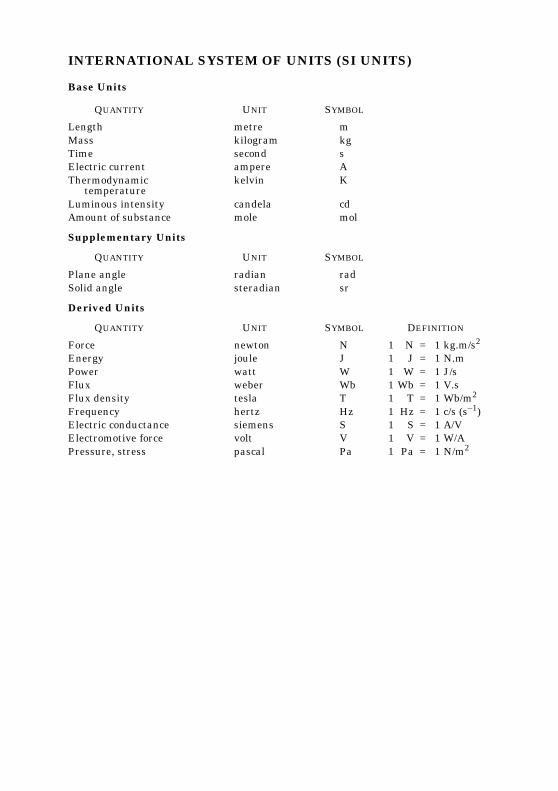
INTERNATIONAL SYSTEM OF UNITS (SI UNITS)
Base Units
QUANTITY UNIT SYMBOL
Length metre mMass kilogram kgTime second sElectric current ampere AThermodynamic
temperaturekelvin K
Luminous intensity candela cdAmount of substance mole mol
Supplementary Units
QUANTITY UNIT SYMBOL
Plane angle radian radSolid angle steradian sr
Derived Units
QUANTITY UNIT SYMBOL DEFINITION
Force newton N 1 N = 1 kg.m/s2
Energy joule J 1 J = 1 N.mPower watt W 1 W = 1 J/sFlux weber Wb 1 Wb = 1 V.sFlux density tesla T 1 T = 1 Wb/m2
Frequency hertz Hz 1 Hz = 1 c/s (s–1)Electric conductance siemens S 1 S = 1 A/VElectromotive force volt V 1 V = 1 W/APressure, stress pascal Pa 1 Pa = 1 N/m2
Bureau of Indian StandardsBIS is a statutory institution established under the Bureau of Indian Standards Act, 1986 to promoteharmonious development of the activities of standardization, marking and quality certification ofgoods and attending to connected matters in the country.
CopyrightBIS has the copyright of all its publications. No part of these publications may be reproduced in anyform without the prior permission in writing of BIS. This does not preclude the free use, in the courseof implementing the standard, of necessary details, such as symbols and sizes, type or gradedesignations. Enquiries relating to copyright be addressed to the Director (Publications), BIS.
Review of Indian StandardsAmendments are issued to standards as the need arises on the basis of comments. Standards are alsoreviewed periodically; a standard along with amendments is reaffirmed when such review indicatesthat no changes are needed; if the review indicates that changes are needed, it is taken up forrevision. Users of Indian Standards should ascertain that they are in possession of the latestamendments or edition by referring to the latest issue of ‘BIS Catalogue’ and ‘Standards : MonthlyAdditions’.This Indian Standard has been developed by Technical Committee : BDC 22
Amendments Issued Since Publication
Amend No. Date of IssueAmd. No. 1 November 1988
BUREAU OF INDIAN STANDARDSHeadquarters:
Manak Bhavan, 9 Bahadur Shah Zafar Marg, New Delhi 110002.Telephones: 323 01 31, 323 33 75, 323 94 02
Telegrams: Manaksanstha(Common to all offices)
Regional Offices: Telephone
Central : Manak Bhavan, 9 Bahadur Shah Zafar MargNEW DELHI 110002
323 76 17323 38 41
Eastern : 1/14 C. I. T. Scheme VII M, V. I. P. Road, KankurgachiKOLKATA 700054
337 84 99, 337 85 61337 86 26, 337 91 20
Northern : SCO 335-336, Sector 34-A, CHANDIGARH 160022 60 38 4360 20 25
Southern : C. I. T. Campus, IV Cross Road, CHENNAI 600113 235 02 16, 235 04 42235 15 19, 235 23 15
Western : Manakalaya, E9 MIDC, Marol, Andheri (East)MUMBAI 400093
832 92 95, 832 78 58832 78 91, 832 78 92
Branches : AHMEDABAD. BANGALORE. BHOPAL. BHUBANESHWAR. COIMBATORE.FARIDABAD. GHAZIABAD. GUWAHATI. HYDERABAD. JAIPUR. KANPUR. LUCKNOW.NAGPUR. NALAGARH. PATNA. PUNE. RAJKOT. THIRUVANANTHAPURAM.VISHAKHAPATNAM