Embed Size (px)
Citation preview

Disclosure to Promote the Right To Information
Whereas the Parliament of India has set out to provide a practical regime of right to information for citizens to secure access to information under the control of public authorities, in order to promote transparency and accountability in the working of every public authority, and whereas the attached publication of the Bureau of Indian Standards is of particular interest to the public, particularly disadvantaged communities and those engaged in the pursuit of education and knowledge, the attached public safety standard is made available to promote the timely dissemination of this information in an accurate manner to the public.
इंटरनेट मानक
“!ान $ एक न' भारत का +नम-ण”Satyanarayan Gangaram Pitroda
“Invent a New India Using Knowledge”
“प0रा1 को छोड न' 5 तरफ”Jawaharlal Nehru
“Step Out From the Old to the New”
“जान1 का अ+धकार, जी1 का अ+धकार”Mazdoor Kisan Shakti Sangathan
“The Right to Information, The Right to Live”
“!ान एक ऐसा खजाना > जो कभी च0राया नहB जा सकता है”Bhartṛhari—Nītiśatakam
“Knowledge is such a treasure which cannot be stolen”
“Invent a New India Using Knowledge”
है”ह”ह
IS 10178 (1995): CO2 gas shielded metal arc welding ofstructural steels - Recommendations [MTD 12: WeldingApplications]

IS ‘Wl78’: 1995
Indian Standard
COzGASSHIELDED METAL-ARCWELDINGOF STRUCTURALSTEELS-RECOMMENDATIONS
( First’ Revision )
l
ICS 25*160*10 : 77.080.10
. Q BIS 1995
BUREAU OF INDIAN STANDARDS MANAK BHAVAN, 9 BAHADUR SHAH ZAFAR MARG
NEW DELHI 110002 0
Noyember 1995 Price Group 5
. *
Arc Welding Applications and Thermal Cutting Sectional Committee, MTD 12
FOREWORD
This Indian Standard ( First Revision ) was adopted by the Bureau of Indian Standards, after the draft finalized by the Arc Welding Applications and Thermal Cutting Sectional Committee had been approved by the Metallurgical Engineering Division Council.
This standard was first published in 1981. While reviewing the standard in the light of experience $ gained during these years, the Committee decided to revise it to bring it in line with the present
practices being followed by the Indian Industry.
The CO3 gas shielded metal-arc welding is becoming increasingly popular in the fabrication of boilers, pressure vessels, ship’s hull, etc. This standard has been prepared as a guide to the industry, dealing with the theoretical and practical aspects of the process.
In this revision, following changes have been made:
a) Electrode extension values have been modified,
b) Typical melting rates have been modified, and
c) Details of welding processes through high current techniques have been mod~ified.
While formulating this standard, necessary assistance has also been derived from the following publications:
CO, Welding of steel. The Welding Institute, Abington, UK.*
For the purpose of deciding whether a particular requirement of this standard is complied with, the final value, observed or calculated, expressing the result of a test, shall be rounded off in accordance with IS 2 : 1960 ‘Rules for rounding off numerical values ( revised J’. The number of significant places retained in the rounded off value should be the same as that of the specified value in this standard.
k-510178:1995
Indian Standard
CO2 GASSHIELDEDMETAL-ARCWELDINGOF STRUCTURALSTEELS-RECOMMENDATIONS
( First Revision )
1 SCOPE
This standard covers recommendations on equipment, consumables, general procedure and technique for semi-automatic and automatic carbon dioxide gas shielded metal arc welding of weldable structural steels, including tubes and hollow sections.
2 REFERENCES
The following Indian Standards are necessary adjuncts to this standard:
IS No. Title
307 : 1966
812: 1957
Carbon dioxide ( second revision )
Glossary of terms relating to weld- ing and cutting of metals
Carbon steel castings for general engineering purposes ( fourth revision )
1030: 1989
2002 : 1992
2062 : 1992
3600 (Part 1) : 1995
6419 : 1971
6560 : 1972
Steel plates for pressure vessels for intermediate and high teniperatnre service including boilers ( thinl revision )
Steel for general structural Pur- poses (fourth revision )
Crucifirm fillet well tensile test ( second revision )
Welding rods and bare electrodes for gas shielded arc welding of structural steel
Molybdenum and chromium molybdenum low alloy steel weld- ing rods and base electrodes for gas shielded arc welding
3 TEBMINOLOGY
For the purpose of this standard the definitions given in IS 812 :1957 shall apply.
4 PARENT METAL
This standard applies to CO2 gas shielded metal-arc welding including overlaying ofweldablequality struc- tural steels conforming to IS 2062 : 1992, IS 1030 : 1989, IS 2002 : 1992 and similar steels.
5 WELDING CONSUMABLES
5.1 The bare wire electrodes shall conform to IS 6419 : 1971, and IS 6560 : 1972 as appropriate.
5.2 Carbon dioxidegas shall conform to IS 307 : 1966.
6 EQUIPMENT
8.1 Power Source
The CO2 gas shielded arc welding process is influenced by the static load characteriskic and the dynamic proper- ties of power source. Only welding generators or rec- tifiers having flat to slightly drooping V-A characteristics and good dynamic properties are suitable. For better monitoring of welding parameter, the power source shall incorporate voltmeter and am- meter.
6.2 Wire Feed Unit
6.2.1 The wire feed unit consists of a feed motor, sets of feed and drive rollers and wire guiding arrangement. The feed rates vary from 2 to 10 m/min. It shall have proper speed regulator to give uniform and smooth feed almost without inertia, from wire reel to the welding gun and to the welding zone. As it controls the welding current, this aspect is more important when higher range of feed rates are used. The unit shall have suitable starting and stopping controls and an inching switch.
6.2.2 For welding thin sheets, the wire feeding device may be incorporated into the welding gun itself ena- bling uniform wire feeding even with extremely thin wire and producing uniform quality welds. It shall be light enough to be manoeuvred by the operator without fatigue in semi-automatic welding.
6.3 The Welding Gun
The welding gun shall have ‘Start’-‘Stop’ switch and ensure uniform transport of wire. A hollow cable con- sisting of a wire-spiral leads the wire electrode from feed rollers to the gun. One current terminal is con- nected to the contact nozzle through which passes the electrode. The contact nozzle is surrounded by a gas nozzle, which shall emit flow of shielding gas between the nozzle and the surface of the parent metal without turbulance. The gun is mounted on the travelling car- riage in automatic welding.
6.3.1 The welding gun may either be gas cooled or water cooled. The guns should be-rated adequately for the intended continuous intermittent use within permis- ,sible temperature limits of usage.
NOTE -Air cooling is generally sufficient up tp* 400 A, Above 400 A water cooling is necessary especially for automatic welding ( 100 percent duty cycle ).
1
IS -10178 : 1995
6.4 Mains and Control Unit
Main unit shall consist of a protective transformer and a rectifier to supply current to the control unit. It may be incorporated in the rectifier power source itself or may be a separate unit in case of generators. The protective transformer is required for safety and to enable welding work on boilers and tanks.
6.4.1 The control unit contains all controlling and switching elements, the pressure operated switch for cooling water (if used), solenoid valve for releasing CO2 gas during the welding processes and other con- trols like timers for spotwelding and automatic welding processes. The wire feed unit is generally coupled with it. The wire feed regulator is also housed in it.
6.5 Instruments and Ancillary Equipment
The flow rate of CO2 gas should be adequate to obtain a clean weld. This depends on several factors such as welding current, welding speed, electrode diameter joint geometry and local conditions. It generally varies from 15 to 22 litres/min.
65.1 A suitable gas flow-meter is mounted just after the pressure regulator and gas heater. Generally CO;? gas is drawn from cylinders and the heater shall be able to prevent CO2 ice formation due to gas expansion. The flow meter should give direct flow-rate readings for CO2 gas in litres/min and should have proper protective covering against breakage.
63.2 The cooling device for water cooled welding gun, consists of a pump withmotor, a water tank and a heat exchanger. For gas cooled torches shielding gas itself will cool the torch.
6.53 The wire feed unit along with the control unit and the welding gun are mounted on a travelling carriage in case of automatic welding. The travelling speed of carriage shall be infinitely regulable within theweiding speed range.
7 ELECTRODE EXTENSION
7.1 The free end protruding out of contact nozzle carries high current densities (over 100 A/mm2). An increase in this length results in the increase of melting rates. However, the arc-current falls with increase in the protruding length. This is particularly noticeable when welding in deep grooves where a narrow joint prepara- tion limits the access of the nozzle, Excessive protrud- ing length will, therefore, lead to lack of penetration unless special techniques are used as in narrow-gas welding.
7.2 Recommended values of electrode extension are given below for various current levels:
Current Electrode Extension A mm
50 - 151! 10-13
?.50 - 3.50 13-18
350 - 400 18-21
7.3 Recommended nozzle to work distance for various current levels are given below:
Current Nozzle to Work Distance A mm
50 - 150 13
150 - 350 15
350 - 400 18
8 POLuuTY
The electrode is generally connected to positive pole. Only in cases such as overlaying, negative pole is come&d to the electrode in order to take advantage of higher melting rates and low penetration.
9 JOINT PREPARATION
9.1 Due to deep penetration, special edge prepara- tion for thin plates is not required. For example, with a 1.6 mm diameter electrode, 12 mm thick plates can be welding with square butt joint (with a joint gap of 3 mm) from both sides at a welding current of 330 to 370 A axial spray transfer techni- que. With thicker plates or thinner electrodes it is sufficient to have a steep V-joint with an included angle of 30 to 400.
9.2 When preparation of the fusion faces is necessary this shall be done by shearing, chipping, machining, gas-cutting or any other method provided the require- . ments of 9.3 are complied with.
9.3 Fusion Faces
93.1 Fusion faces shall be smooth and free from slag, lamination, notches or other irregularities which might be the cause of defects or would affect adversely the quality of weld and the workmanship.
9.3.2 Fusion faces and the surfaces adjacent to the joint for a distance of at least 50 mm on either side of the joint shall be free from heavy scale, moisture, oil, paint or any other substance which might affect the quality of the weld or impede the progress of welding.
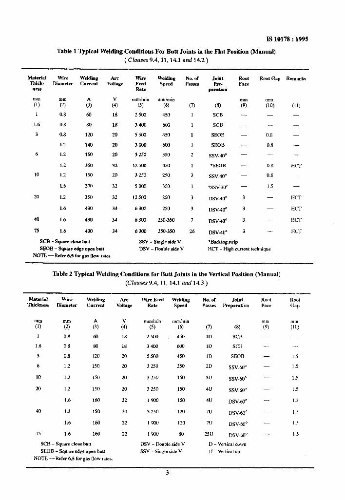
9.4 Typical details of joint are given in Tables 1 to 4.
10 WELDING POSITION
It is possible to weld all types of joints in all welding position by CO2 gas welding process. For difficult positions like vertical and overhead weld- ing, electrodes up to 1.2 mm diameter with lower welding voltage (19-23V) and current (SO-155A) are used.
11 BACKING AND FIT-UP
If backing strips are not to be used, tolerance on root gaps and alignment of parts should be maintained closely to control penetration. Typical details of joints are given in Tables 1 to 4.
3
IS 10178 : 1995
Table 1 Typical Welding Conditions For Butt Joints in the Flat Position (Manual)
( Clauses 9.4, 11,14.1 and 14.2 )
Material Wire Weldiig Arc Thick- Diameter Current Voltage
ness
mm
(1) :; A x
1 0.8 60 18
1.6 0.8 80 18
3 0.8 120 20
1.2 140 20
6 1.2 150 20
1.2 350 32
10 1.2 150 20
1.6 37@ 32
20 1.2 350 32
1.6 430 34
40 1.6 430 34
75 1.6 430 34
SCB - Square close butt
SEOB - Square edge open butt
NOTE -Refer 6.3 for gas flow rates.
WiFe Wddklg Feed SF& Rate
mm/min mm/min
(5) (6)
2500 450
3400 600
5500 450
3000 600
3 250 350
12 500 450
3 250 2.50
5000 350
12 500 250
6300 250
6300 250-350
6306 250-350
SSV - Single side V
DSV - Double side V
No. of Passes
(7>
1
1
1
1
2
1
3
1
3
3
I
26
Joint Pre-
paration
(8)
SCB
,SCB
SEOB
SEOB
ssv-40°
*SEOB
ssv-4o”
*ssv-30°
DSV-40°
DSV-40°
DSV40°
DSV-480
‘Backiog strip
Rod Face
77 - - - - - - - - 3
3
3
3
Root Gap Remarks
mm
(10)
-
-
0.8
0.8
-
0.8
0.8
1.5
-
-
-
-
(11)
-
-
-
-
-
HCT
-
HCT
HCT
HCT
HCT
HCT - High current technique
Table 2 Typical Welding Conditions for Butt Joints in the Vertical Position (Manual)
(Ciauses 9.4, 11, 14.1 and 14.3 )
Material Wii Welding Ildclawss JXametw current
7 ?G A
1 0.8 60
1.6 0.8 80
3 0.8 120
6 1.2 150
10 1.2 150
20 1.2 150
1.6 160
40 1.2 150
1.6 160
75 1.6 160
SCB - Square close butt
SBOB - Square edge opeo butt
NOTE-Refer 6.5 for gas flow rates.
AS-C Wirr Feed Welding No. of Joint Voltage Rate Speed Passes PlTparation
G 18
18
20
20
20
20
22
20
22
22
mmlmin mm/mm
(5) (6)
2500 450
3400 600
5500 450
3 250 2.50
3 250 150
3 250 150
1900 150
3250 120
1900 120
1900 80
DSV - Double side V
SSV - Single side V
(7) (8)
1D SCB
1D SCB
1D SEOB
2D SSV-60”
3u SSV-60“
40 ssv-60”
4u DSV-60“
7u DSV-60”
7u DSV-60’
25U DSV-60’
D - Vertical down
U - Vertical up
Root Root Face Gap
“I”, “I m
(9) (10)
- -
-- -
- 1.5
- 1.5
- 1.5
- 1.5
- 1.5
- 1.5
- 1 s
- 1.5
IS 10178 : 1995
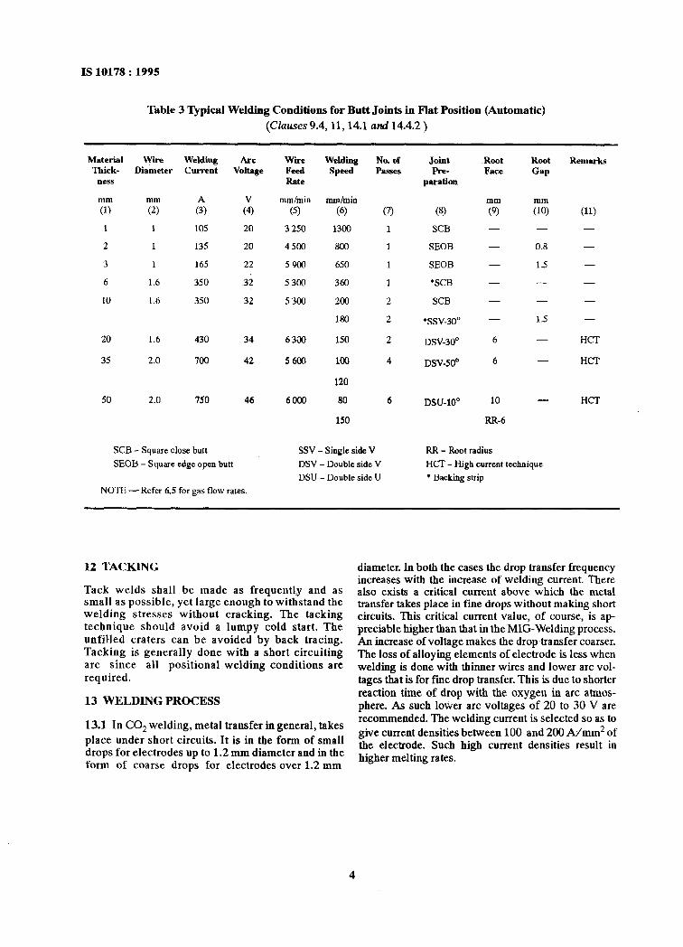
Table 3 ‘Qpical Welding Conditions for Butt Joints in F’lat Position (Automatic)
(Clauses 9.4,11,14.1 and 14.4.2 )
Material ‘Ihick-
ness
mm
(1)
1
2
3
6
10
wii Weldi Arc
Diameter cm-rent Voltage
1 105 20
1 135 20
1 165 22
1.6 350 32
1.6 350 32
wiie Fed Rate
mmhnin
(5)
3 250
4.500
5900
5300
5300
20 1.6 430 34 63a
35 2.0 700 42 5600
50 2.0 750 46 6000
Welding No. of Speed Passes
Joint Pm-
ppratiCMl
Root Root Face Gap
Remarks
mmlmin
(6)
1300
800
650
360
200
180
150
100
120
80
150
Q 1
1
1
1
2
2
2
4
6 DSU-10’ 10 - HCT
(81 SCB
SEOB
SEOB
‘SCB
SCB
‘SSV-3o”
DSV-30’
DSV-SOa
6
6
RR-6
- -
0.8 -
SCB - Square close butt
SEOB - Square edge open butt
NOTE - Refer 6.5 for gas flow rates.
SSV - Single side V RR - Root radius
DSV - Double side V HCI - High current technique
DSU - Double side U * Backing strip
12 TACKING
Tack welds shall be made as frequentl,y and as small as possible, yet large enough to withstand the welding stresses without cracking. The tacking technique should avoid a lumpy cold start. The unfilled craters can be avoided by back tracing. Tacking is generally done with a short circuiting arc since all positional welding conditions are required.
13 WELDING PROCESS
13.1 In CO, welding, metal transfer in general, takes
place under short circuits. It is in the form of small drops for electrodes up to 1.2 mm diameter and in the form of coarse drops for electrodes over 1.2 mm
diameter. In both the cases the drop transfer frequency increases with the increase of welding current. There also exists a critical current above which the metal transfer takes place in fine drops without making short circuits. This critical current value, of course, is ap- preciable higher~than that in theMIG-Welding process. An increase of voltage makes the drop transfer coarser. The loss of alloying elements of electrode is less when welding is done with thinner wires and lower arc vol- tages that is for fine drop transfer. This is due to shorter reaction time of drop with the oxygen in arc atmos- phere. As such lower arc voltages of 20 to 30 V are recommended. The welding current is selected so as to give current densities between 100 and 200 A/mm2 of the electrode. Such high current densities result in higher melting rates.
IS 10178 : 1995
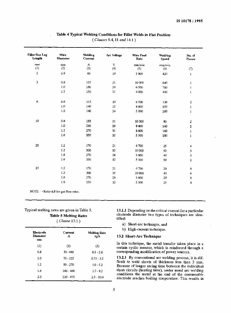
Table 4 Typical Welding Conditions for Fillet Welds in Flat Position
( Clauses 9.4, 11 and 14.1 )
Fiet Size Leg Wire Welding Arc Voltage Wire Feed
Length Diameter Welding No. of
Current Rate Speed P2lSSeS
T TT c$ K
mm/min mmlmin
(9 (6’ (7)
2 0.8 60 18 3000 420 1
3 0.8 1.55 21 10 ccl0 640 1
1.0 180 24 6 SO0 760 1
1.2 150 21 4000 480 1
6 0.8 115 20 6 500 130 2
1.0 140 22 4800 150 1
1.2 180 24 SO00 2cNl 1
10 0.8 15s 21 10 000 90 2
1.0 230 26 9400 140 2
1.2 210 31 8600 160 1
1.6 350 32 5300 180 1
20 1.2 170 21 4 700 25 4
1.2 300 35 10 m so ~3
1.6 270 26 3600 40 3
1.6 350 32 5300 50 2
25 1.2 170 21 4 700 20 9
1.2 300 35 10 coo 40 6
1.6 270 26 3600 20 8
1.6 250 32 5 300 25 4
NOTE-Refer 6.5 for gas flow rates.
Typical melting rates are given in Table 5.
Table 5 Melting Rates
( Clause 13.1 )
Electrode Diameter
mm
(1)
0.8
1.0
1.2
1.6
2.0
ClJnwl~ Melting Rate A kPm
(2) (3)
50 -180 0.5 - 2.8
70 - 22s 0.75 - 3.5
SO-270 1.0-5.2
160-400 1.7 - 9.2
220 - 475 2.5 - 10.0
5
13.1.1 Depending on the critical current for a particular electrode diameter two types of techniques are iden- tified:
a) Short-arc technique, and
b) High-current technique.
13.2 Short-Arc Technique
In this technique, the metal transfer taken place in a certain cyclic manner, which is reinforced through a corresponding modification of power sources.
13.2.1 By conventional arc welding process, it is dif- ficult to weld sheets of thickness less than 3 mm. Because of longer arcing time between the individual short circuits (heating time), under usual arc welding conditions the metal at the end of the consumable electrode reaches boiling temperature. This results in
IS 10178 : 1995
higher heat inputs in the parent metal leading to deeper fusion penetration and corresponding bigger weld pool in case of thinner sheets because of slower heat dissipa- tion by the parent metal. In short arc process, the overheating of the consumable electrode end, the ex- cess heat input in the parent metal is prevented by reducing the heating time. This is achieved by modification of short-circuiting process through shor- tening of arc.
13.2.2 This requires a dc set with flat to slightly droop ing static characteristic. An additional inductance nor choke is required to limit the short circuit current to improve the dynamic characteristics.
13.23 When the metal transfer takes place with short circuits the electrode~end dips in the weld pool. The short circuit is broken by the factors which are also responsible in other processes. After opening of short circuit an arc of higher current is produced. Due to its higher pressure a crater is formed in the weld pool. The breaking of short circuit causes the inductance to build up a back e.m.f. due to which the welding current and voltage decrease. It results in reduction of the arc- pressure on the weld pool decreasing thereby the crater depth. This means the distance between the electrode and the weld pool surfaces (arc length) is reduced. The melting rate is also reduced with the fall of current, thereby breaking the equilibrium between the melting rate and the wire feed. The electrode end, therefore, approaches the weld pool. The arc lengtb is, thus reduced faster till the electrode again comes in contact with the weld pool.
13.2.4 These short-circuits take place at a rate of 100 to 200 times per second. For the stability of this special melting process, the static characteristics of the dc source and the value of inductance play a majorrole. The value of inductance should correspond correctly to the electrode diameter, welding current and the electrode extension. Generally 0.8, 1.0 and 1.2 mm diameter electrodes with current densities of 100 to 200 A/mm2 are used in this process.
13.3 Hlgb Current Technique
In this CO2 gas welding process the electrode carries current in the range of 300 A per mm of diameter of wire. This results in better productivity because of higher melting rates and increased fusion penetra- tion. The spatter loss is also reduced. Generally 1.2, 1.6 and 2.0 mm diameter electrode are used in this process.
13.3.1 The higher current densities affect the mode of metal transfer. Above critical current, which, for ex- ample, is 350 A for 1.2 mm diameter electrode and 450 A for 1.6 mm diameter electrode, the metal transfer is in small drops at higher frequency and without short circuits. However, the typical spray-type mode of drop transfer encountered in MIG-welding is not reached in this process.
133.2 In this technique, the heating times of drops at the electrode end is less because of higher drop-fre- quency. As such the loss of alloying elements is lower,
although due to higher currents, higher voltages are to be used.
13.33 The. high-current technique brings. more -ad- vantages in welding of thicker plates (higher melting rate and deeper penetration) and in overlaying (high melting rate, less loss of alloying elements). The disad- vantages are bigger weld-reinforcements band to some extent poor weld appearance.
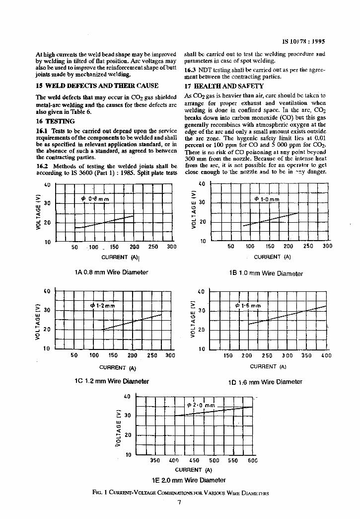
13.4 Recommended current voltage combination for various wire diameters are given in Fig. 1.
13.5 CO2 Spot Welding
The welding pistol is so designed that the shielding gas nozzle can sit properly on the parent metal surface and withstand the necessary holding force.
Generally 1.6 mm diameter electrode are used. The arc is established after switching on the wire feed by short circuiting the electrode with the parent metal. The current density varies from 120 to 200 A/mm’. The welding time controlled by time varies from 0.8 to 2.0 sec.
14 WELDINGPARAMETERS
14.1 Recommendations are given for power source up to 750 A in Tables 1 to 4. For automatic welding heavy duty machines are necessary as welding can be done at much higher speeds than those obtained with semi- automatic operation. These tables may be used to make other joints with slight changes in the parameters.
14.2 Downhand Welding
Typical parameters are given in Table 1. Some data, as indicated, refer to high-current technique.
14.3 Vertical Welding
In Table 2 typical welding conditions are given for vertical welding. Sheets invertical position are normal- ly welded in vertically down position as it gives better control over penetration. In making butt welds the root run is normally deposited without weaving to avoid over-penetration. For thicker plates, it is better to weave into the root and to use a 50” V or U preparation to get better access to the joint.
14.4 Automatic Welding
14.4.1 Co,? gas metal-arc welding lends itself well to mechanization. Certain welds such as edge welds and outside comer cannot be effectively made by manual welding; whereas they could be made satisfactorily by mechanized CQ gas metal arc welding. This is due to the precision with which the arc can be directed with machine control.
14.4.2 In mechanized welding there is considerable increase in welding speeds. Sheet size material can be welded at a speed of 2500 mm/mitt. Typical conditions are given in Table 3.
14.43 Excessive welding speed result in undercutting although this can be improved by welding with a slope.
6
At high currents the weld bead shape may be improved by welding in tilted of flat position. Arc voltages may also be used to improve the reinforcement shape of butt joints made by mechanized welding.
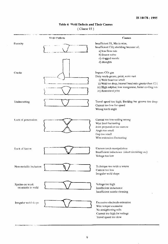
15 WELD DEFECTS AND THEIR CAUSE
The weld defects that may occur in CO, gas shielded metal-arc welding and the causes for these defects are also given in Table 6.
16 TESTING
16.1 Tests to be carried out depend upon the service requirements of the components to be welded and shall be as specified in relevant application standard, or in the absence of such a standard, as agreed to between the contracting parties.
16.2 Methods of testing the welded joints shall be according to IS 3600 (Part 1) : 1985. Split plate tests
shall be carried out to test the welding procedure and parameters in case of spot welding.
16.3 NDT testing shall be carried out as per the agree- ment between the contracting parties.
17 HEALTB AND SAFETY
As CO2 gas is heavier than air, care should be taken to arrange for proper exhaust and ventilation -when welding is done in confined space. In the arc, CO2 breaks down into carbon monoxide (CO) but this gas generally recombines with atmospheric oxygen at the edge of the arc and only a small amount exists outside the arc zone. The hygenic safety limit lies at 0.01 percent or 100 ppm for CO and 5 000 ppm for CO2. There is no risk of CO poisoning at any point beyond 300 mm from the nozzle. Because of the intense heat from the arc, it is not possible for an operator to get close enough to the nozzle and to be in any danger.
40
F - 30
9
2 20 >
40
S
IL! 30 c!J Q l- 2 20 >
10 50 100 150 200 250 300
CURRENT (A)(
10 50 100 150 200 250 300
CURRENT (A)
1A 0.8 mm Wire Diameter 1B 1.0 mm Wire Diameter
z 30 UJ
: = 20
9
101” ” ” ’ 11 111 50 100 150 200 250 300
CURRENT (A)
;: 2; 30 a a
= 20 \
>”
,Ol I I I I I I I I I I I1 150 200 250 300 350 400
CURRENT (A)
1C 1.2 mm Wire Diameter 1 D I;6 mm Wire Diameter
HS 101178 : 1995
40
Z 30 w
2 2 20 0
3
350 400 450 500 550 6OG
CURRENT (A)
IE 2.0 mm Wire Diameter
FIG. 1 C URRFNFVOLTAGE COMFSIMIYGPJS,FOR VARIOUS WIRE DIAMETERS
7
1!310178:1995
However, a good ventilation of working place is a must. Ultraviolet radiation can also produce severe sunburn
Because of CO2 welding is an open arc process, which effects on exposed areas of the face, neck and arms.
can employ high currents, radiation can be a problem. This can happen not only to the welder but to other
Excessive ultraviolet radiation on an unprotected eye personnel who may be working some distance from
will give rise to the condition known as ‘arc eye’, when welding areas where high current arcs are being used.
irritation is set up and the eyes becomes painful and Local screening of the arc zone is suggested for
watery. There is intense photophobia and the acute preventing sunburn effects. Reflective surfaces around
symptoms may last for one or two days. Although no the area should be kept to a minimum.
permanent damage is done,accidental exposure should In a properly ventilated shop, CO;! welding causes no be avoided by proper screening of personnel working ill effect on the welders who are regularly employed for near welding position. it.
8
IS 10178 : 1995
Table 6 Weld Defects and Their Causes
( Clause 15 )
Porosity ..‘. ‘- -. .
I-__
“‘--y-.. . ” /
Cracks
Undercutting
Lack of penetration
Lack of fusion
Non-metallic inclusion
Spatter-on work on nozzle in weld
Irregular wcl :I 41,1\)e
Causes
Insufficient Sl, Mn in wire,
Insufficient CO2 shielding because of,
a) low flow rate
b) frozen valve c) clogged nozzle
d) draughts
Impure CO2 gas
Dirty work-grease, paint, scale rust
i) Weld bead too small ii) Weld too deep, internal bead ratio greater than 12: !
iii) High sulphur, low manganese, faster cooling rate
iv) Restrained joint
Travel speed too high, Backing bar groove too deep’
Current too low for speed
Wrong torch angle
Current too low-setting wrong
Wire feed fluctuating Joint preparation too narrow
Angle too small Gap too small
Wire-extension lluctuating
Uneven torch manipulation
Insufficient inductance (short circuiting arc)
Voltage too low
Technique-too wide a weave
Current too low Irregular weld shape
Voltage too high
Insufficient inductance
Insufficient nozzle cleaning
Excessive electrode extension
Wire temper excessive
No straightening rolls
Current too high for voltage
Travel speed too slow
_-._ .-
Bureau of Indian Standards I-=-
BIS is a statutory institution established under the Bureau of Indian Standards Act, fY86 to promote harmonious development of the activities of standardization, marking and quality certification of goods and attending to connected matters in the country.
Copyright
BlS has the copyright of all its publications. No part of these publications may be reproduced in any form without the prior permission in writing of BIS. This does not preclude the free use, in the course of implementing the standard, of necessary details, such as symbols and sizes, type or grade designations. Enquiries relaling to copyright be addressed to the Director ( Publications ). BIS
Review of Indian Standards
Amendments are Issued to standards as the need arises on the basis of comments. Standards are also reviewed periodically; a standard along with amendments is reaffirmed when such review indicates that no changes are needed; if the review indicates that changes are needed, it is taken up for revision. Users of Indian Standards should ascertain that they are in possession of the latest amendments or edition.
This Indian Standard has been developed from Dot: No. MTD 12 (3880).
Amendments Issued Since Publication
Amend No. Date of Issue Text Affected
i.
Headquarters:
.,’ . 1
::.
“BUREAU OF INDIAN STANDARDS
Manak Bhavan, 9 Bahadur Shah Zafar Marg. New Delhi 110002 Telegrams : Manaksanstha Telephones : 331 01 31, 331 13 75 ( Common to all offices )
Regional Offices : Telephone
Central : Manak Bhavan, 9 Bahadur Shah Zafar Marg NEW DELHT 110002
Eastern : l/14 C. I. T. Scheme VII M, V. 1. P. Road, Maniktola CALCUTTA 700054
Northern : SC0 335-336, Sector 34-A, CHANDIGARH 160022
Southern : C. 1. T. Campus, IV Cross Road, MADRAS 600113
331 01 31 331 13 75
37 84 99, 37 85 61
37 86 26, 37 86 62
{
60 38 43 60 20 25
235 02 16, 235 04 42 235 15 19, 235 23 15
Western : Manakalaya, E9 MIDC, Marol, Andheri ( East ) 832 92 95, 832 78 58
BOMBAY 400093 832 78 91, 832 78 92
Branches : AHMADABAD. BANGALORE. BHOPAL. BHUBANESHWAR.
COIMBATORE. FARIDABAD. GHAZIABAD. GUWAHATI. HYDERABAD.
JAIPUR. KANPUR. LUCKNOW. PATNA. THIRUVANANTHAPURAM.
PrInted at New In&e l’rlnting Pmss. Khurla. hi,,