Embed Size (px)
Citation preview

IRSE NEWS ISSUE 150 NOVEMBER 2009

Front Cover: A view of the operating floor inside the signalling control centre at Rugby, overseeing part of the West Coast Main Line in the UK.
Photo: Network Rail
RAILWAY SIGNALLING CAREERS, SYDNEY AUSTRALIAUnited Group Infrastructure specialises in the delivery of turnkey rail systems solutions, and has developed unrivalled technical expertise in key rail systems; signalling, communications, traction power, overhead electrification and specialist track infrastructure.The Signalling Solutions division is one of the largest private sector suppliers of design construction and maintenance capability in signalling and railway network systems in Australia and New Zealand; offering our clients a wide range of services from design and construction to complete signalling, communication and train control systems for heavy haul, passenger and light rail projects.UGL Careers is seeking expressions of interest for upcoming projects in our Sydney operation:
Y Signal Design EngineerY Senior Signal Design Engineer
To send your resume please visit:http://www.uglcareers.com/opportunities.phpclick UGL Infrastructure, and enter job code 440 or for more information please call Fiona Weir on +61 7 3833 1904.
Y Project EngineerY Project ManagerY Design Manager
SIMS is a Link-up and ISO 9001 accredited Equal Opportunities company that provides a wide range of consultancy and resourcing services to the railway signalling industry, from project conception, through detailed design and installation to testing & commissioning.
We are presently looking to expand our in-house capability to help deliver our current and future workload.
We therefore have immediate opportunities for self-motivated individuals holding IRSE Licences in the following categories:
• Signalling Designer
• Signalling Principles Designer
• SignallingDesignVerifier
• Signalling Functional Tester
• Signalling Principles Tester
• Signalling Tester in Charge
We are particularly interested in hearing from individuals who hold Signalling Principles Designer and SignallingDesignVerifierLicences. Experience of preparing and verifying designs for conventional London Underground signalling systems would be an advantage, but we can offer the necessary instruction and mentoring to achieve the required level of competence where necessary.
Weoffer competitive ratesona contract basis and the benefitofworking in a professional yet friendly environment based near Fenchurch Street in the City of London.
Closing date for applications is 30th November 2009.
To apply for any of the positions listed above please send your CV via email to: [email protected]
www.simsrail.co.uk
SIGNALLING INSTALLATION & MAINTENANCE SERVICES LTD

IRSE NEWS | ISSUE 150 | NOVEMBER 2009
IRSE NEWS is published monthly by the Institution of Railway Signal Engineers (IRSE). The IRSE is not as a body responsible for the opinions expressed in IRSE NEWS.
© Copyright 2009, IRSE. All rights reserved. No part of this publication may be reproduced, stored in a retrieval system, or transmitted in any form or by any means without the permission in writing of the publisher. Copying of articles is not permitted except for personal and internal use. Multiple copying of the content of this publication without permission is always illegal.
Editor Ian J Allison 31 Bainbridge Road, Loughborough, LE11 2LE, UK Tel: +44 (0) 7794 879286 e-mail: [email protected]
Deputy Editor Tony Rowbotham 36 Burston Drive, Park Street, St Albans, AL2 2HP, UK e-mail: [email protected]
Assistant Editors (Overseas) Tony Howker e-mail: [email protected]
(Younger Members) Nigel Handley e-mail: [email protected]
Contributions Articles of a newsworthy or technical nature are always welcome for IRSE NEWS. Members should forward their contributions to one of the Editors listed above.
Advertising For advertising rates and deadlines call Christopher Bean at Ten Alps Publishing Tel: +44 (0)20 7878 2415 Fax: +44 (0)20 7379 7118 e-mail: [email protected] Advertisements are accepted on the basis that the advertiser and agency (if any) warrant that the advertisement contents are true and correct in all respects.
Web Site For up to date information about the Institution or its activities, or to download a membership application form, log on to the IRSE Web Site: www.irse.org
Production IRSE: Stuart Angill, Production Manager Printing and Mailing: Fericon, Reading
London Office IRSE, 4th Floor, 1 Birdcage Walk, Westminster, London, SW1H 9JJ, United Kingdom
Enquiries
MEMBERSHIP OR OF A GENERAL NATURE Tel: +44 (0)20 7808 1180 Fax: +44 (0)20 7808 1196 e-mail: [email protected]
PROFESSIONAL DEVELOPMENT Tel: +44 (0)20 7808 1186 e-mail: [email protected]
LICENSING Tel: +44 (0)20 7808 1190 e-mail: [email protected]
1
NEWS VIEW 150 A Global Role
IN THIS ISSUE Page
Signalling: Have we lost the plot? (London November Paper) 2 Eddie Goddard
Semi-automatic, driverless, and unattended operation of trains 8 IRSE International Technical Committee
Australian Competency Management Systems – Signalling Design 11 Martha Gordillo
Complexity and Safety: A Case Study 16 George Nikandros
Interesting Infrastructure: Lincoln Co-acting Signals 21 J D Francis
Industry News 22 Book Review: Compendium on ERTMS 25 David Slater
Axle Counter & Technology Seminar 26 Walter Peckruhn
Narrow gauge points - An economical approach 29 Stuart Marsh
IRSE Matters Correction to Printed Programme Card 32 News from New Zealand 32 Younger Members 33 Minor Railways Section 34 Midland & North Western Section 37
Signalling Pioneers: C B Byles Ken Burrage 38 Feedback 40 Membership Matters outside back cover
Front Cover: A view of the operating floor inside the signalling control centre at Rugby, overseeing part of the West Coast Main Line in the UK.
Photo: Network Rail
Another milestone achieved in the history of IRSE NEWS. This is a good moment for some reflection. A couple of questions are appropriate in order to test the magazine.
Is the magazine productive? After a slower start (22 years for the first 100) the speed of publications is now gathering pace, with only five years needed for the next 50. That means that from just over 2.5 months between issues, the waiting time for the anxious reader has now been reduced to less than half. Eleven Issues per year with several hundred pages in total is the current status. That is a good sign when it comes to measuring productivity.
Then what about the content? Also here we see a change in both topic and depth. We cannot say it was a straight track over the last five years (and sometimes it was a bit bumpy seeing the heated discussions on some topics) but I hope you agree with me in stating that the current content matches the expectations of many members.
Is the magazine attractive? I think it is. From a somewhat dull image in line with our role as keepers of the safety of the railway we now have a magazine that does invite reading. The new layout is a good step forward. It is in line with many magazines with a much bigger print number and where teams of multiple professional members dedicate themselves to the mock-up and layout of the articles.
Is this good enough? No, I do not think so, but not because of the magazine and the dedication of the team that makes it happen, together with the happy volunteers who submit the articles. It is the because of the role of the IRSE which is becoming more and more global. That change will force the magazine into a new direction. The magazine needs to show more about the world wide activities of the Institution so that the members get information about technology, processes and, above all, events that are relevant to them in their geographical context. That is the challenge. Good luck in the future.
Frans Heijnen, IRSE President

IRSE NEWS | ISSUE 150 | NOVEMBER 2009 2
NOVEMBER PAPER
INTRODUCTION This paper has two themes. The first concerns the need to ensure the continuity of signal engineers able to see the big picture. The second looks at the way that signalling is provided and, in particular, the role of assurance in the signalling process.
It endeavours to show that there are linkages between the two and that the industry has to face up to the changes that have taken place. Finally it proposes a way forward to enable the signalling industry to remain economic and efficient.
It relies heavily on the author’s experience and so is written from the point of view of UK Metro signalling in the United Kingdom. It should not be seen as relating to any particular organisation. However it attempts to bring in the experience of national railways and of other countries.
SCENE SETTING Is perception reality? The following are views currently held by many outside the signalling industry and often expressed by those within it (see Ref. 1).
They don’t make them like they used to. “When the current breed of signal engineers retire there will
be no one left that understands the whole picture. All that we have now are specialists.”
The weight of evidence. “The amount of documentation for a project generated to
satisfy the assurer(s) outweighs that used to develop the project itself. The critical path now lies through the assurance chain. As a result project cost and implementation time are becoming untenable.”
Why do these things matter? If they are true, then the cost of introducing new systems will become unbearable, signalling unaffordable and delays unacceptable. If we do not do something we will be left behind. Railways themselves will become uneconomic and will fall into decline. The benefits that they can bring will be lost, and we will all be out of a job. Even if they are not true the perception is still there, and unless we are able to counter it the signalling industry will be marginalised and investments made elsewhere (see Ref. 2). What is more likely is that new companies will be formed which are more willing to adopt new ways and able to undercut the traditional suppliers through adopting a radical approach.
THEY DON’T MAKE THEM LIKE THEY USED TO Career Development To develop these themes the paper will consider the career of a typical signal engineer of an earlier generation—as experienced by the author at the time.
Training A total apprenticeship of six years, starting as a Dip Tech Trainee.
Doing Design Producing “red inks” by copying the work of the Engineering Assistant (just two years older than myself!), then preparing circuits and having them checked. Being given feedback on the design and hence learning the best way. Seeing the approver work with the Engineering Assistant and his experience being fed back. Later still, seeing the two principal designers in active debate about the more esoteric aspects of the design.
Installation Held the meter for the Principal Installation assistant (Tester in charge). Observed the final commissioning process where the tester, without reference to the circuits but used the scale plan and working from first principles ensured that the site performed as it should by using track dropping boards and lots of staff. Saw design anomalies picked up and circuit changes made through the designer sitting alongside the tester. Later, put in charge of testing a signal! Realising the homework that went into the testing process with study of circuits, and discussion of the designs before testing took place.
Signalling: Have we lost the plot? By Eddie Goddard Paper to be read in London on 11 November 2009
Academic English, Maths and Physics at school. Sponsored for a Degree in Electrical and Telecommunications Engineering, and a Master’s Degree in Systems Engineering.
Practical Time spent in workshops, with the Maintainer on call and with an installation gang. Knowledge gained of practicalities, as well as the cultures of the different disciplines.
Signalling theory
Power Signal Linesman course and Drawing Office course.
Management theory
British Rail junior management course.
Railways Time spent with Divisional Inspector on stations and with drivers, looking into incidents and observing his staff management. Absorbing front-line operator’s culture.
Time spent in control rooms and generally out and about on the railway.
Project Produced a railway simulator for the Victoria Line through extensive work with rolling stock engineers to understand train characteristics.
Testing New communications system on live rails in an automatic train area. On the track, no lookouts, no briefing, no personnel protection equipment.
The author is a past President of the IRSE

IRSE NEWS | ISSUE 150 | NOVEMBER 2009 3
Development Put in charge of making a new communications system work. Working directly with supplier’s team and devising modifications. Jointly installing and testing them.
Railway Working with Rolling Stock Engineers, spending considerable time with Line Controllers and Train Regulators and riding in train cabs.
Management Working in a multidisciplinary team with a senior operator, timetable compiler, Data Processing expert, on specification of a computer based railway control system.3
Consultancy Providing independent assurance to signalling contractors for novel signalling systems through London Transport’s external consultancy arm. As a result exposed to other countries’ signalling cultures, and to commercial pressures.
Managing Development Leading the team introducing computer control systems for the Underground. Providing the engineering support to the cross-directorate team (engineering, operations, revenue collection, supplier) developing the Underground’s automatic fare collection and selling systems (became Oyster) with the supplier.
Maintenance Responsible for the signalling maintenance division.
Client Managing the Signalling client organisation.
Systems Managing the Rolling Stock and Signalling client organisations, and forming the Systems Engineering team.
International committees Working on standards-setting committees for RIA, ORE, and the IRSE technical committee. Gaining wider appreciation of different signalling and operating companies, different cultures, and different commercial arrangements.
Professional career Supported throughout career on IRSE activities, attending lectures and conventions as a student, granted time to attend council meetings, through to support during presidential year.
Assuring Chief Engineer Managing the team that produces standards and enforces compliance for all engineering disciplines.
Chairman of safety review panels Approving introduction of new technology and systems.
Career Development Underlying all the above was the certain knowledge that a full career could be followed through one employer; that the training manager had mapped out the early stages and provided mentoring through those difficult times; and that the senior managers had devised career progression plans, and that one’s promotion was often subject to those plans. Sideways and even downward moves were encouraged, with the promise that “rescue would be at hand” should the move prove to be too disastrous.
The Signalling World Railways Railways were largely self-contained. They did everything themselves. (London Underground even had its own power generating stations).
They were staffed to a great extent by former soldiers and mariners, and organised as operations, engineering disciplines, and support. Each engineering discipline was led by a Chief Engineer accountable for development, design, installation and maintenance. The Chief made decisions, right or wrong, and was accountable for them. He knew all aspects and was capable of, and indeed far too frequently did, issue detailed designs himself (Robert Dell when Chief Signal Engineer would issue his circuits in green ink so that everyone knew not to question them!)
Suppliers Suppliers built what they were asked to build. Research and development were carried out jointly under profit sharing agreements, with engineering decisions being made first and commercial consequences agreed later. Engineers worked together as a team, each having his own role. When things went wrong, they fixed them. The result was often gold-plated signalling - thank goodness, because most of it is still in commission, and working well beyond its expected life of forty years.
Safety Safety was embodied in the fail-safe concept. Every effort was made to understand the failure modes of components and eliminate the causes of wrong side failures (see Ref. 4). As a result interface problems were greatly simplified, in that each component in the chain took on trust that the preceding ones would fail safe and so did not have to consider any complex interactions.
Reliability was seen as subservient to safety.
On London Underground a clear distinction was made between safety and non-safety circuits, so that the safety circuitry was kept as simple as possible (see Ref. 5).
Personnel safety was largely based on drumming into people just how dangerous the railway was, and then expecting them to look after themselves. As a result working on the railway was seen as the second most dangerous occupation, after the mining industry.
Assurance Although the word “assurance” would not have been recognized in this context then, the pursuit of ever-increasing levels of safety was ingrained in all signal engineers, and closely linked to the hierarchical chain. Engineering managers were technically competent in the main, and had risen through the ranks. They were fully empowered to manage, they made decisions and they managed the budgets. They were accountable for delivery to cost and to time, and for the quality of the end result.
Designs were “Checked” and “Approved” by the design engineer’s manager as part of the normal production process. They would sign off the designs only when satisfied that they were correct. Schemes were approved by the Design Engineer. Independent checking was carried out between drawing offices and through discussion with the installers and testers.
Components were tested in the supplier’s factory and signed off by competent inspectors, 100% checking being the norm. Critical components were retested by the railway.
Installers’ work was checked by wire counts and testing initially, to prove that

IRSE NEWS | ISSUE 150 | NOVEMBER 2009 4
NOVEMBER PAPER the circuits worked as designed (verification). Then it was checked by a senior tester to ensure that it met all the signalling principles and enabled the operator to run the intended service safely (validation). At each stage a simple signature sufficed.
Close attention was paid to every failure and the root cause was sought, be it equipment, procedural or human error.
Her Majesty’s Railway Inspectorate – the Regulator HMRI staff were traditionally ex-military. They saw their role as that of an enforcer, but they always had the clear motivation to improve the railway and its safety and to protect the workforce. They looked to ensure that there was adequate paperwork, but spent most of their time talking to the people - operators, engineers and managers alike. They sought evidence principally through testing the calibre of the people they talked to.
They gave approvals following a staged interrogation. “Cooksey’s Court” was always something that had to be prepared for, and it nearly always surprised with the perception of the questions asked (see Ref.6).
They were able to turn a blind eye on occasions but let the managers know they had done so.
They conducted enquiries with the aim of finding out why the accident had happened and preventing it happening again.
FROM THEN TO NOW Education Engineering as a profession fell out of fashion, and universities have struggled to recruit good school leavers. In a survey in 1997 only 60% of schoolchildren over 16 had even heard of engineering as a career, less than 3% were interested in railways (see Ref. 7). Sponsorship for engineering courses and apprenticeships became scarce. The few graduates that emerged were attracted to lucrative careers in finance. As a result the flow of young engineers all but dried up. Poor publicity about railways made it hard to recruit from even this depleted pool of talent.
Railways The old monoliths have been broken up. On national railways, operation has been franchised to train operating companies, rolling stock is provided by rolling stock companies, signalling and permanent way by infrastructure companies.
Even in Metros the maintenance has often been franchised out, and new signalling and rolling stock provided by outside suppliers.
Suppliers Suppliers have formed into large international consortia. They have been required to take on many of the roles previously performed by the railway companies.
At the same time they have continued to concentrate on manufacture, with application design, installation, commissioning, maintenance and assurance often being franchised out to smaller, niche companies.
Safety Safety has become an industry in itself. Companies have been formed or consultancies have taken on the role of assurer. In part this is through the requirements for independent safety assurance to satisfy the requirements of EN61508 and for Notified Bodies to satisfy the European Commission’s need to demonstrate fair competition.
It is also however a reflection of how difficult it is to meet the expectations of the safety industry itself - that is, to prepare safety cases, proofs of safety, safety plans etc. in order to demonstrate that the requirements arising from the criterion, “As Low As Reasonably Practicable” have been met.
Software and communications-based systems are more difficult to understand than the old signalling circuits. It is harder to see the whole picture The introduction of project managers separate from engineers results in a tendency for the engineers to concentrate on quality and leave the need to meet timescales and budgets to the project manager, and vice versa. As a result decisions are often made in practice by the person with the most power rather than the one with the best knowledge.
Regulation Perhaps the biggest change was the need for regulators to reflect the change that had taken place in public perception. It is no longer the case that “accidents happen.” It is necessary to show that someone is to blame. As a result court cases follow any accident, and evidence is required to demonstrate that correct procedures have been followed. Engineering judgement alone is no longer acceptable as an explanation for decisions. Even regulators find their decisions questioned and action threatened against them.
As a result the whole industry has become highly defensive. It is no longer wise to be a single decision maker. Regulators see their role as being protectors of the public first, improvers of the railway second.
More recently in the UK the ROGS regulations (see Ref. 8) have placed greater emphasis on the safety management system and the need to demonstrate adherence to it, and have recognised the need for collaboration between parties. Written verification plans identify the roles of the parties and where review is required, the level of intrusion required being risk-based.
THE WEIGHT OF EVIDENCE The net result of the move from simple, fail-safe components to the need to prove a system to be safe, with the use of software in vital systems, combined with the demand for documented evidence of every stage of the process in order to satisfy a potential court of law has resulted in an industry that has definitely “lost the plot.”
The basic elements of design, checking and approval are still recognisable throughout the supply chain, but part of their purpose has been lost. The essential learning feedback from master to pupil has been replaced by assurance. There is often a culture in which the assurer feels obliged to find fault. At its most extreme it manifests itself in the form “This is wrong but I will not tell you why it is wrong” - an approach based upon the mistaken belief that it will cause the submitter to find all the other examples of error.

IRSE NEWS | ISSUE 150 | NOVEMBER 2009 5
In many cases the errors found are due to carelessness. Too often though they stem from the submitter’s lack of local, domain knowledge. In other cases they stem from a lack of specialist knowledge of the product or interfaces. In some cases “errors” are the result of straightforward opinion engineering on the part of the assurer.
In extreme cases, specialist assurance writers are employed who have no knowledge of the product and simply reprocess paperwork without checking with the originators.
Despite this demand for a structured approach, capturing requirements fully and determining the test criteria at the commencement of a project remain beyond us. Hence a lot of the document-ation, when submitted, reflects the changes that have had to be made along the way. As a result, even in well-run projects, documentation tends to lag behind production. Frequently this results in a need to employ specialists to produce safety plans, safety cases, proofs of safety etc. All too often these specialists are from another company, and nearly always they are not the people doing the actual work.
This in turn leads to another tranche of documentation as the doers, testers, commissioning agents, operators and maintainers finally catch up with the process and request permission to operate. All too often this is at the point of maximum pressure on the project to meet deadlines, when relationships between the companies are at their most strained. As a result, assurance becomes the scapegoat for late delivery.
WHAT HAS TO BE DONE Career Development
Education The first stage is to tackle the lack of schoolchildren taking maths and science. At least this has now been recognised and Mathematics education is improving. We all need to spread the word.
In the United Kingdom the “Science, Technology, Engineering and Maths Ambassador” or “STEM Ambassador” programme is helping to address this.
The next need is to encourage schoolchildren to opt for engineering. For Transport for London, Project Brunel supported by the Royal Academy is
tackling this, and it needs our support. Most importantly all sectors of the
industry need to address the issue and reinstate apprenticeships, graduate training etc. Universities need to be encouraged to provide degree and postgraduate courses to meet this need. In this regard the UK is certainly lagging behind the rest of Europe as well as China and India, where technical universities have greater status and where Railways, and even Railway Signalling specifically, are seen as suitable subjects for first degree courses.
Training There is a belief that market forces will magically provide the incentive needed for young engineers to plot their careers and, by suitable movements between companies, obtain the breadth of training required to take on senior positions. In a few cases this has indeed worked, but the fact that this paper has been called for demonstrates that overall it has failed to produce the numbers required.
The greatest need is to provide a career path that enables suitable young engineers to gain the breadth of understanding necessary to become a fully-fledged signal engineer and manager of signalling. The move back to integrated infrastructure companies places an onus on these companies to reinvigorate their training approach. Similarly the major signalling suppliers need to recognise the need to invest in the future, looking to move suitable candidates around the divisions so that they can gain experience in marketing, development, installation and, where possible, maintenance.
Finally all companies should provide opportunities for young school leavers by providing graduate training courses, and the universities should be encouraged to provide modular training that will enable students to pick and mix and still acquire the degrees that they need to satisfy the Institutions.
The biggest gap remains the lack of opportunity to gain experience of railway operation. There is clearly a need to provide training opportunities and to give suitable candidates a chance to take on roles closer to the operation of the railway. For Metros this is still possible, as signalling and train operation are normally in the same company. As an example,
recent London Underground signalling trainees have qualified as train drivers. For the national railways the split between train operating companies and infrastructure managers makes it much more difficult. Surely a protocol could be drawn up so that all share the burden?
Suppliers’ engineers need to be given access to the railway so that they can place their promising engineers in posts that will give them the experience they need. As the infrastructure managers need to ensure that their own engineers gain experience of the problems of production and of research and development, some form of mutual cooperation seems once again to be desirable. Again the simplest approach would appear to be a protocol that enables staff to be swapped between companies.
Consultancies provide the ideal training ground in many ways, spanning all areas of signalling and all countries. It is vital that they contribute to the development of engineers from the start and support the efforts of industry and the railways. There is a tendency for the mature engineers to end their careers in consultancy and thus the mentoring of the younger engineers is lost - or even made the subject of contracts!
The final, and probably the greatest, concern is the need to address the specialist companies. There is a need to find software engineers with the requisite knowledge of the railway, and safety specialists who understand the reality of railway engineering. Many sub-contractors providing installation and maintenance staff, companies specialising in providing test and commissioning engineers - are too small to sustain a training course themselves and in any case too specialised to be able to provide the opportunities needed in-house.
Today’s signalling manager must be able to work with many disciplines, to work in a complex commercial environment and to integrate diverse teams from different companies. Technical skills are less important than managerial and team-building skills. The abilities to get the best from people and to ask the right questions at the right time are essential. Good judgement remains the greatest requirement, and it needs the

IRSE NEWS | ISSUE 150 | NOVEMBER 2009 6
NOVEMBER PAPER manager to have a broad background, but that can be gained in different ways. It is no longer necessary to have done every-thing, indeed it is no longer possible.
Equally there is a need for specialists, able to concentrate on one area of the industry, but these too must be given the opportunity to broaden their knowledge and learn the basics of signalling and railway operation.
Proposal A potential solution to all the above is to take an idea from the environmental lobby with the Carbon Tax. If all companies were to recognise the need for signalling training, and to accept a training levy offset by the offering of training posts and suitable publicity produced to show that this is an integrated scheme, that would attract people into the profession with the knowledge that railways, and signalling in particular, are worth coming into as a career. That would enable engineers to select the training they require without having to chop and change between companies.
It would give companies an incentive to establish training schools and courses, and to support the existing training companies. Whilst this is a potential problem it has generally been recognized and training facilities have been provided or enhanced to address the shortage of signalling technicians.
The IRSE could provide a framework to enable this to be organised by the companies themselves. All that is needed is a simple pro-forma for placements and a means of identifying the places available.
ASSURANCE The first, and greatest, problem is that no one company is capable of doing everything and so the work must be split amongst a number of companies. No-one can get their head around the whole picture. The Chief Engineer of today would be hard-pressed indeed to know all the detail of the software, communications, equipment, testing procedures and maintenance capability.
The simple philosophy of fail-safe can no longer be applied, so that the signalling must be seen as part of a system and all interfaces must be considered and defined clearly.
Keep it simple What the signalling is required to do has expanded, and capturing those requirements is a major task in itself. The clear distinction between what is required to keep trains safe and all the other functions that the signalling performs has become blurred. The fact remains that trains are subject to the basic laws of nature and so plausibility tests can easily be built into the systems.
Greater use should be made of two basic principles in the approach to signalling: keep the safety element of the system as simple as possible; and employ diversity to reduce dependence on any one element.
Use industry standards It is no longer possible to test every path through the logic, and issues of timing and interaction need to be considered. The software industry has however developed tools to cover every element of the life-cycle. Signalling needs to embrace these tools, while avoiding the temptation to cite every one as mandatory for SIL 4 systems.
There needs to be a realisation that safety integrity (SIL) levels were developed as a shorthand way of putting software-based systems into a safety context. Numbers were added to provide parallels with the standard failure modes, effects and criticality or FMECA (Failure Mode, Effects & Criticality Analysis) approach possible with discrete components.
A clear plan for the assurance processes to be adopted and definition of the level of assurance to be applied at each stage, and which company/individual will be responsible at each stage, will reduce the overlap - checkers checking checkers - and enable adequate planning and time to be made available.
Systems approach Signalling must therefore embrace the systems engineering approach and work to clear assurance processes, but the current divide between assurers and doers must be bridged nevertheless.
If requirements are properly captured, acceptance criteria identified at the outset and changes rigorously controlled then the classic model for verification and validation can be followed and the result is a largely self-assured product.
If assurers throughout the supply chain are prepared to accept less than perfect English and Grammar then the need to spend time rewriting documents can be eliminated. If parties communicate throughout, the need for reports and statements can be greatly reduced.
Modelling One approach is to make greater use of modelling as part of the specification process. It is generally much easier to define what is wanted if the potential users are able “to see it and play with it,” rather than trying to specify it in abstract terms. Well-constructed models also provide a basis for the suppliers to work from, and can even be used to set the final acceptance criteria.
Greater reliance on simulation for testing with more emphasis placed on proving the accuracy of the models removes some of the need for site testing. Accurate models also enable suppliers to test their interfaces with other suppliers in a controlled environment.
Self documentation Automated testing tools provide self documentation; comprehensive logging of events and interim states enables self documented testing.
Accurate simulators also enable operators to gain skills in the new system, and can be incorporated into the training documentation and even the safety case.
In short, we need to return to the principle that assurance arises from doing the right thing and being able to evidence it, not from writing reams of paper.
Data A great deal of attention is paid to the safety of the underlying system and to the processes applied to its production. In practice the most vulnerable part of the process lies in capturing and inputting the data that characterise the system. This is often delegated to the most junior members of the team, and is only proven through testing the installation itself. Attention needs to be paid to means of reducing the dependence of the system on the accuracy of data through diversity, plausibility, and automated testing.

IRSE NEWS | ISSUE 150 | NOVEMBER 2009 7
Domain knowledge None of the above, however is any substitute for common sense. It is essential that somewhere in the chain a check is made by someone with knowledge of the particular application. Ideally the person checking the data should be knowledgeable. The principles tester must be able to see the big picture and know how the system will be used. Ideally the systems architect will have, or will have access to, a rounded signal engineer.
Paperless assurance By applying the above the reliance on error-free software and data should be reduced, systems should be self checking, verification and validation built into the production process, and the safety case built around the production process. In the end assurance comes from a knowledge that the system has been designed in such a way as to enable it to operate safely, that the right people have done all that can reasonably be expected of them and that they have been supported by the application of sufficient process controls to trap any errors that might have crept in.
The emphasis must be on getting it right first time, feeding back any shortcomings found and improving the process at all stages; targeting any surveillance activity on a risk basis and applying basic common sense, placing greater trust on the producers and using the resources to improve their knowledge and skills.
Public opinion Of course, a greater change could be made if public opinion were to be made aware of the heavy cost the current regime imposes, but experience shows that whilst this might be possible in normal times, the immediate reaction to an accident, and the public outcry that follows, will mean that such considerations will be ignored in the endeavour to find out who is to blame. It remains the case therefore that paperwork will be needed to provide an audit trail.
ENCORE It has been remarked that rather than losing the plot the author has not recognised that he is in the wrong play! The world moves on, what used to be is no longer practicable. It is not possible to reconstruct the past, but the aim of this paper has been to use the experience of previous generations to show that there are alternatives to today’s accepted UK norm. As yet other countries have avoided the worst examples but are far from immune, and much stems from an interpretation of European directives.
If the Railway of the 1960s was the prequel, still highly dependent on the Victorian past, the railway of today is much safer (see Ref. 9) and the new processes have enabled it to adopt the new technology. What of the sequel? We must move to overcome the issues that this paper has raised. Most importantly we must ensure that we have the actors in place, with the right scripts.
ACKNOWLEDGEMENTS Many people have contributed to this paper, both wittingly and unwittingly! The author would like to thank the President for the opportunity and David Waboso for permission to produce this paper, though it must be emphasised that the opinions expressed are the author’s alone and should not be seen as referring to any particular organisation or company.
REFERENCES 1 President’s Address: A sustainable
profession? Where are we going? IRSE NEWS May 2009
2 Towards the one page safety case IRSE Technical Committee, IRSE NEWS June 2009
3 Computer controlled signalling and regulation, Eddie Goddard, IRSE Proceedings, December 1974
4 ORE report A118 5 Automatic Junction working and Route
Setting by Programme, Robert Dell, IRSE Proceedings, October 1958
6 Monitoring Railway Safety - Are we doing it the right way? IRSE March 1990
7 Project Brunel Final Report, Franklin Andrews, December 2008
8 UK legislation, The Railways and Other Guided Transport Systems (Safety) Regulations 2006
9 Railway risks, safety values and safety costs, Andrew W Evans, Imperial College, London

IRSE NEWS | ISSUE 150 | NOVEMBER 2009 8
INTERNATIONAL TECHNICAL COMMITTEE
SUMMARY The mission of any metro transportation undertaking is to provide safe, reliable, efficient, high quality service to its passengers in a cost effective fashion. To meet this business need, our metro systems are increasingly being automated. Any new metro system constructed today would almost certainly incorporate some level of automation with many modern metro systems now providing driverless or unattended train operation. In addition, higher levels of automation are also being introduced into the older metro systems around the world in response to demands for increased capacity on the existing infrastructure, enhanced levels of safety, improved customer service, and reduced operating costs.
This article examines the benefits of automation, the various levels of automation that can be deployed, the maturity of the technology, and the challenges of selecting the appropriate level of automation for a specific application. The article focuses on automation of metro systems. Automation of our intercity main lines, high speed railways, and freight lines will be addressed in a separate article.
THE BENEFITS OF AUTOMATION Metros are an expanding business with many existing metros operating at or near to their capacity limit. Given the often prohibitively high costs of constructing new metro lines or extending platform lengths, the benefits of automation are therefore invariably linked to maximising the operational performance of the existing or planned transportation infra-structure. The characteristics of automation that support this goal include the following:
Automation of the train driving functions can provide for more regular and predictable run times between stations, eliminating the variations inherent with manual driving, and providing for a more uniform ride quality and reduced wear-and-tear on train propulsion and braking systems;
Driverless/unattended train operation, with automatic passenger door opening and closing and automatic train departure from station platforms, can further reduce the variations in line operation. Unattended train operation also frees the metro operator of the constraints imposed by the need to provide for the rostering of train crews and provides the flexibility to operate shorter trains more frequently;
Unattended train operation, when combined with fully automated maintenance yards and stabling tracks, also provides the flexibility to respond to unexpected increases in passenger demands by adding additional trains to the service, all without requiring additional train drivers or manual intervention;
While automation can reduce operating staff costs, the reductions in cost associated with a reduction in train drivers have to be offset by any increase in staff costs for any additional passenger service and security personnel, as well as any additional maintenance costs associated with the automation system itself;
Automation of turnbacks at terminal stations can reduce turnover times, reducing the number of train sets needed for operation;
Automation of train regulation, train dispatching and train routing functions can more effectively regulate the performance of trains in relation to timetable (schedule) and/or headway adherence. Regulation can be achieved by automatically adjusting dwell times and/or by automatically controlling run times between stations (e.g., through adjustments to train acceleration and service brake rates, and speeds);
Automation of train regulation functions can also facilitate appropriate train meets, such as transfers between local and express tracks, and at the merge point between different lines in order to minimize overall system delays;
The automatic, real-time control and coordination of train acceleration, train coasting, and train braking can also be utilized to implement energy optimization algorithms for example though coasting controls or by synchronizing the acceleration of one train with the braking of another train to maximize use of brake energy recovery;
Automated failure detection and response can be more effective in responding to system disturbances and emergencies through the elimination of human error.
While subjectively the benefits of automation may be self evident, quantifying these benefits in order to develop a specific business case is very application-specific and dependent upon the particular level of automation that is adopted.
LEVELS OF AUTOMATION The first step in automating any metro system is the automation of the primary safety functions through continuous, automatic train protection (ATP). With this foundation in place, the driving functions themselves can then be automated through the provision of automatic train operation (ATO). With the driving functions automated, real-time automation of the train management and train regulation functions becomes possible, through more sophisticated automatic train supervision (ATS) systems, providing operational benefits at the line/network level.
The term ATO is used to cover a wide range of levels of automation, from the automation of the basic driving operation alone to the running of trains with no staff member on board. An IEC working group (TC9 Working Group 40) and the European MODURBAN project have therefore adopted the concept of
Semi-automatic, driverless, and unattended operation of trains IRSE International Technical Committee

IRSE NEWS | ISSUE 150 | NOVEMBER 2009 9
levels of “Grade of Automation” (GOA), with GOA level 1 being ATP only with no ATO (ref. IEC 62290-1).
At its most basic, ATO enables trains to run automatically from one station to the next, under the protection of an ATP system and under the supervision of a train driver. This mode of operation is referred to as Semi-automatic Train Operation (STO) or GOA level 2. With STO, the operation of the train’s motors and brakes is automated providing a more consistent form of driving with funda-mental benefits to the railway in terms of capacity and energy consumption. Typically, the driver remains in the cab of the train, operates the doors, provides the start signal for the train to leave a station, and monitors the performance of the train and the track ahead.
More sophisticated systems free the driver from the need to be at the front of the train – referred to as Driverless Train Operation (DTO) or GOA level 3. In DTO the driver is able to move away from the front of the train, but remains available to provide customer facing duties and to drive the train in the event of a failure of the ATO system. As the driver is no longer able to see the route ahead this imposes a greater demand on guideway security and platform controls. In DTO, train doors and train departure from a station platform may be controlled automatically or manually from a location other than a drivers cab at the front of the train. The increased flexibility that derives from freeing the train service operation from having to provide a driver at the front of each train means, as a minimum, that the time that would be required for a driver to walk from one end of the train to the other when reversing can be saved, thereby increasing the throughput at terminal stations and sidings.
Driverless ATO without an on-board attendant is referred to as Unattended Train Operation (UTO) or GOA level 4. UTO can range from empty train movements only (to a siding, or in an automated depot for example) to the operation of trains in passenger service with no attendant on board. The latter requires that the train can be operated remotely under failure conditions, or at the minimum can be reached by shore based personal in a short period of time. Passengers need to be reassured and
hence good communication links between the vehicle and an informed staff member are essential. Automation of the door operation is now mandatory and requires means of detecting trapped articles of clothing or children. Increased protection of the guideway from intrusion or some form of obstacle detection is also required. Apart from the savings in staff costs the greatest benefit with unattended operation is that train service can be tailored directly to demand with trains being brought into service as and when the demand increases.
The benefits of the various levels of automation are summarized in the following table:
Whilst signalling and train control systems provide the foundation of an ATO railway, it is improvements in the security and communication systems that are the main difference between traditional manually driven trains and driverless or unattended operation. UTO for example typically requires the addition of passenger operated plungers on stations and trains to summon help in an
Benefit STO DTO UTO
Automatic Train Protection (ATP)
√ √ √
More predictable run times between stations
√ √ √
More uniform ride quality √ √ √
Reduced wear-and-tear of train propulsion/braking systems
√ √ √
Energy optimization √ √ √
Reduction in variations in line operation / improved service regulation
√ √
Automation of turnbacks √ √
Remove constraint of rostering train crews
√
Flexibility to operate shorter trains more frequently
√
Ability to respond to unexpected increases in passenger demands
√
Potential for reduction in operating costs
√
Automated failure detection/response
√
emergency, extensive CCTV with links to a manned control centre, obstacle detection systems, and automatic platform area supervision to detect persons on the track. As an alternative to intrusion detection systems, platform edge doors may also be used to prevent access to the track in platform areas.
An IEC working group (TC9 Working Group 45) has recently completed a document addressing the safety requirements for fully automated (driverless/unattended) metro systems which should be released as an official IEC standard (IEC 62267) by late 2009. This document specifically addresses safety aspects applicable to driverless systems and does not include functions that would be the same whether or not there is a driver onboard the train (e.g. interlocking functions). In addition, the safeguards that are recommended in this standard to mitigate identified generic hazards may not apply in all situations and the metro authority and specific regulatory regime has the ultimate responsibility to determine, through hazards analysis, if a given safeguard is required.
ATO TECHNOLOGY MATURITY ATO can be superimposed on any form of continuous supervision-based ATP and as a consequence the introduction of ATO on urban mass transit railways was closely linked to the transition from wayside signalling technology to cab-signalling technology in the latter half of the last century. London Underground’s Victoria Line, which entered service in 1968, is generally regarded as the first ATO metro line. The Victoria Line signalling is based on fixed-block technology and the train driver closes the train doors and presses a pair of "start" buttons to depart a train from a station platform. If the way ahead is clear, the ATO system drives the train at a safe speed to the next station and stops there. The Victoria Line would therefore be classified as semi-automatic train operation (STO). The only other STO line on the London Underground currently is the Central Line which introduced ATO as part of a major upgrade of the line during the 1990s. The simultaneous renewal of trains and signalling - and the introduction of ATO – was introduced to make the best

IRSE NEWS | ISSUE 150 | NOVEMBER 2009 10
INTERNATIONAL TECHNICAL COMMITTEE use of the Central Line's capacity and provide important benefits for passengers in terms of more frequent trains, greater comfort, shorter journeys and improved reliability. The implementation of ATO on other lines in the London Underground network is currently underway.
Similar STO systems appeared in the USA in the late 1960s with the PATCO (Port Authority Transit Corporation) Lindenwold line in Philadelphia in 1969, the San Francisco/Oakland BART system in 1972, the Washington Metro (WMATA) system in 1976, the Atlanta Metro (MARTA) system in 1979 and the Miami Metrorail in 1984, for example. The Hong Kong MTR system also adopted fixed-block STO technology when that system first entered service in 1979. Metro Madrid automated its first line, Line 7, in 1996 and has subsequently automated the majority of its other lines with STO.
In all ATO applications the basic principle is to provide a command to the train’s propulsion and braking systems to cause the train to drive at a speed below the safe speed limit, with ATP enforcing the speed limit through the train’s emergency brakes should the train attempt to exceed the safe speed. ATO functions may be implemented in equipment independent of the ATP equipment, or may be integrated with the ATP equipment.
The initial ATO applications used fixed block, coded track circuit technology with “speed codes” to indicate the maximum enforced speed. ATO functionality can also be provided with fixed block “digitally encoded”, profile-based track circuit technology as well as Communications-Based Train Control (CBTC) technology which can support moving-block operations through continuous train-to-wayside and wayside-to-train data communications, and train location determination that is independent of track circuits.
The first example of semi-automated train operations (STO) using CBTC technology was the Scarborough RT line in Toronto which entered service in 1985. Other examples of STO utilizing CBTC technology would include, for example, San Francisco MUNI (1997), Ankara Metro (1997), Hong Kong KCRC West Rail (2003) and New York City Transit Canarsie Line (2006).
The first examples of unattended train operation on a metro line, with no person aboard (UTO), were in Kobe (Japan) in 1982, Lille (France) in 1983 and Vancouver (Canada) in 1985. The Kobe and Lille systems were based on fixed-block technology whereas the Vancouver system utilized CBTC technology. Other examples of UTO utilizing CBTC technology would include, for example, Lyon Line D (1992), Paris Meteor Line (1998), Kuala Lumpur (1998) and Singapore North-East Line (2003). Examples of UTO based on fixed block technology would include Osaka (1982) and Copenhagen Metro (2002).
An example of a driverless train operation but with an onboard attendant (DTO) would be the London Docklands system that first entered into service in 1987 with fixed block technology. In 1994 the line was re-signalled using CBTC technology to increase capacity in response to an order-of-magnitude change in forecast demand.
The examples above are not intended to be an exhaustive list of all ATO systems world-wide, but rather to demonstrate the widespread application of ATO technology over the past 40 years, and to provide an indication of the significant maturity of this technology.
SELECTING THE APPROPRIATE LEVEL OF AUTOMATION While ATO technology is certainly mature, and there are many suppliers capable of providing a wide range of ATO systems, there is however currently no universally accept-ed methodology to determine the appropriate level of automation that should be adopted for a specific metro application. When selecting the level of automation for a new metro line, or when upgrading an existing metro line, the desired operational performance and life-cycle costs should be two important starting points.
It is the operating authorities (and possibly local or national laws or regulations) that typically have the strongest influence on the selection of the appropriate level of automation. Operating authorities in turn often rely heavily on the experience of their own technical staff and/or on the advice of consultants contracted to assist in planning and development activities. Typically, the criteria for selecting a particular level of automation are more subjective in nature, rather than based on a systematic, top-down, business case analysis of the various alternatives.
The selection process is further complicated by a lack of unified standards to document and quantify the benefits of ATO drawn from world-wide experience. Selecting the appropriate level of automation is also often seen primarily as a “signalling” or “train control” decision, rather than considering the desired operating character-istics of the metro system as a whole.
Organised labour unions can also have a significant influence on the selection of the appropriate level of automation given concerns over potential job losses if train drivers cannot be retrained to take on the additional customer service or security functions that are typically required in driverless and unattended train operations.
There may be concerns that some passengers could be reluctant to ride on driverless or unattended trains and this can also influence a decision on the level of automation to be adopted. However this concern is seen to be more of a perception than a reality given the widespread acceptance of such systems by passengers around the world and the proven safety record of such system.
CONCLUSION This article has highlighted the benefits and wide
spread use of automation on metro systems around the world, and the trends towards increased levels of auto-mation in the future. While this article has focused specifically on metro systems, surely it can only be a matter of time before the benefits of increased levels of automation on metro systems will similarly be realized on our main line and high speed railways.

IRSE NEWS | ISSUE 150 | NOVEMBER 2009 11
Introduction
Purpose
The railway industry in Australia does not have uniform standards for the competence of staff working on signalling projects. Currently, each of the engineering disciplines and industry organisations within each state is free to decide what standard is best to ensure competence measures meet the requirements of each state’s Rail Safety Act. This report aims to answer the question of whether it is possible to develop common and transferable standard competences and processes that can be used throughout Australia.
Scope
This study analyses whether the Signalling Designer Competency as defined by the IRSE licence scheme can be recognised as a common standard for ensuring the competence of railway signalling staff in Australia. The scope of this report encompasses:
Analyse competency management system of four rail organisations, focussing on signalling design competence of their staff. Compare the above against the IRSE Licensing Scheme – Designer;
Determine whether the IRSE Licensing Scheme is viable as a baseline for the competency management system of each of the organisations under analysis;
Identify additional information required for the IRSE scheme to be acceptable for national recognition purpose.
The IRSE Licence Scheme has different categories available: Signalling Design, Signalling Installation, Signalling Works Testing, Signalling Maintenance, Telecoms Installation, Telecoms Testing, Telecoms Maintenance and Engineering
Management. Due to time constrains, this study is limited to the Signalling Design category. Also, the research is limited to the states with the larger and most prominent railway administrations – such as NSW (RailCorp and ARTC), Queensland (QR), and Victoria.
Definitions
AQF: Australian Qualification Framework
AQTF: Australian Quality Training Framework
ARTC: Australian Rail Track Corporation Ltd
IRSE: Institution of Railway Signal Engineers
NTF: National Training Framework
QR: Queensland Rail
RISSB: Rail Industry Safety and Standards Board
RTIIC: Rail Tram Industry Infrastructure Committee (Victoria)
RTO: Registered Training Organisation
SOC: Statement of Competency
Background
The updated NSW Rail Safety Bill 2008, which was introduced into NSW Parliament on 24 September 2008, was based on national model legislation and requires that rail transport operators ensure that each rail safety worker on their rail operations has the competence to carry out their work. The rail transport operator must ensure that the competency of safety workers is assessed based on qualification and/or units of competence recognised under the Australian Quality Training Framework (AQTF) / National Training Framework (NTF).
A two year transitional timeframe is provided by the Rail Safety Bill 2008 for the rail transport operators to achieve compliance with its requirements. The guidelines have been revised to:
Amend the requirements for qualifications of trainers and assessors which have been updated to reflect the current Australian Quality Training Framework (AQTF) requirement;
Amend the criteria for issuing certificates of competency to reflect the current Australian Qualification Framework (AQF) terminology;
Clarify the information required as part of the certificates of competency. (‘Changes to ITSRR Guidelines for Certification of Competency’ 2008).
Recently, in order to meet these requirements, rail organisations and private companies have started improving and/or creating processes for the assessment and certification of competency of all staff involved in rail safety work.
Review of Australian Design Competency Systems
RailCorp Design Competency System
To meet the requirements for a rail operator and to satisfy the regulations under the Rail Safety Act, RailCorp has developed a Design Competency System. It applies to RailCorp design staff and contractors including professional service providers engaged by RailCorp, TIDC or RailCorp Program Alliances.
RailCorp has also created a skills competency matrix that contains cross-reference of the specific skills, qualifications and experience required to carry out design tasks in order to prescribe competence levels for that
Australian Competency Management Systems – Signalling Design By Martha Gordillo BEEng, MEngStud, GradDipRailSig United Group Infrastructure, Sydney, Australia
(This article is based on the research project done as part of the requirements for a Graduate Diploma on Railway Signalling, at Central Queensland University.)
COMPETENCY MANAGEMENT
IRSE NEWS | ISSUE 150 | NOVEMBER 2009 12
COMPETENCY MANAGEMENT discipline (‘Engineering Design Competency System’ 2008). Within a Statement of Competency there are levels that certify employees to perform different tasks.
It is necessary to obtain a design competency certificate and/or Engineering Authority to perform design tasks for RailCorp. Depending of the type of engagement with RailCorp, the assessment process to get the certification varies:
If the designer is engaged as internal staff member or contracted directly by RailCorp, the designer needs to apply for a Statement of Competency. In some cases, depending on the role, the designer is also required to apply for Engineering Design Authority;
If the designer works for an external company, which is contracted by RailCorp, RailCorp assesses the company’s design capability during the tendering process and if the tender is granted, it will automatically allocate Engineering Design Authority to the proposed designers. Application for Engineering Authority is not necessary in this case;
If the designer works for an external company, which is contracted by RailCorp Alliances then the designer needs to apply for RailCorp‘s Engineering Design Authority or Statement of Competency dependent on the situation.
ARTC Design Competency System
In order to meet the requirements of the Rail Safety Legislation, ARTC is refining the processes for assessment and certification of competencies of all the staff working on signalling infrastructure or functions associated with design, construction, testing, commissioning and maintenance.
ARTC employees, its contractors and alliance partners must implement processes for assessing the competency of the staff that will be working on signal design tasks.
ARTC competency processes are developed to meet the following principles:
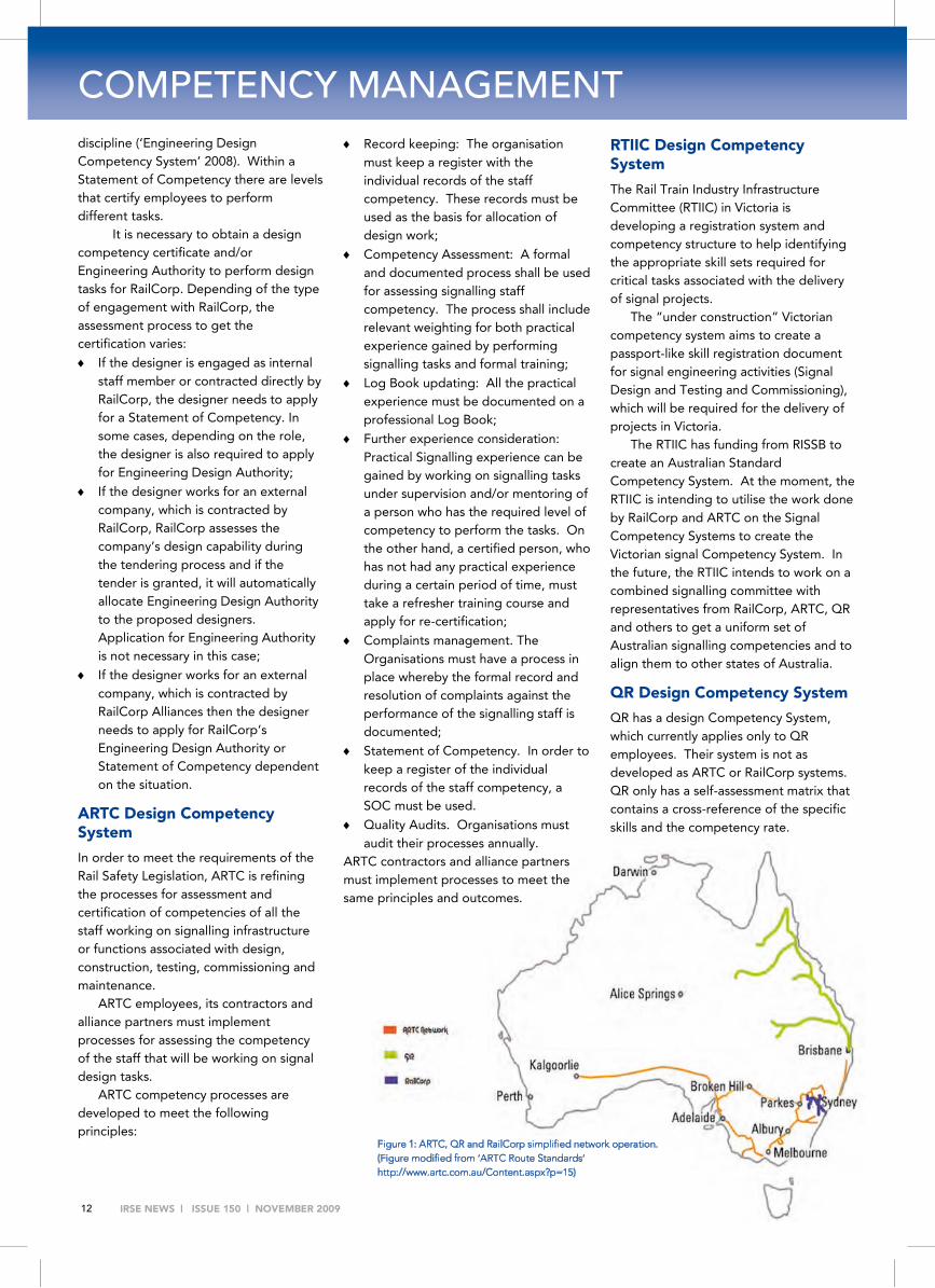
Figure 1: ARTC, QR and RailCorp simplified network operation. (Figure modified from ‘ARTC Route Standards’ http://www.artc.com.au/Content.aspx?p=15)
Record keeping: The organisation must keep a register with the individual records of the staff competency. These records must be used as the basis for allocation of design work;
Competency Assessment: A formal and documented process shall be used for assessing signalling staff competency. The process shall include relevant weighting for both practical experience gained by performing signalling tasks and formal training;
Log Book updating: All the practical experience must be documented on a professional Log Book;
Further experience consideration: Practical Signalling experience can be gained by working on signalling tasks under supervision and/or mentoring of a person who has the required level of competency to perform the tasks. On the other hand, a certified person, who has not had any practical experience during a certain period of time, must take a refresher training course and apply for re-certification;
Complaints management. The Organisations must have a process in place whereby the formal record and resolution of complaints against the performance of the signalling staff is documented;
Statement of Competency. In order to keep a register of the individual records of the staff competency, a SOC must be used.
Quality Audits. Organisations must audit their processes annually.
ARTC contractors and alliance partners must implement processes to meet the same principles and outcomes.
RTIIC Design Competency System
The Rail Train Industry Infrastructure Committee (RTIIC) in Victoria is developing a registration system and competency structure to help identifying the appropriate skill sets required for critical tasks associated with the delivery of signal projects.
The “under construction” Victorian competency system aims to create a passport-like skill registration document for signal engineering activities (Signal Design and Testing and Commissioning), which will be required for the delivery of projects in Victoria.
The RTIIC has funding from RISSB to create an Australian Standard Competency System. At the moment, the RTIIC is intending to utilise the work done by RailCorp and ARTC on the Signal Competency Systems to create the Victorian signal Competency System. In the future, the RTIIC intends to work on a combined signalling committee with representatives from RailCorp, ARTC, QR and others to get a uniform set of Australian signalling competencies and to align them to other states of Australia.
QR Design Competency System
QR has a design Competency System, which currently applies only to QR employees. Their system is not as developed as ARTC or RailCorp systems. QR only has a self-assessment matrix that contains a cross-reference of the specific skills and the competency rate.

IRSE NEWS | ISSUE 150 | NOVEMBER 2009 13
Findings and Recommendations In order to determine whether the IRSE Scheme is viable as a baseline for a National Competence Management System – Signalling Design, a comparison of the IRSE Licence Scheme against the competency management system of each of the organisations analysed was performed.
In the writer’s opinion the RailCorp, ARTC and Victorian Design Competency Systems have been designed to be “upgradeable” to an IRSE licence.
National Licence Postulation
From this point onwards, the following terminology will be used:
National Licence. Hypothetical licence acceptable Australia wide;
Australian Licences. Licences acceptable limited to specific rail operators and/ or regions within Australia such as RailCorp Competency Certification or ARTC Competence Certification or Victorian Statement of competency or the QR Signal Accreditation.
The comparison of the different schemes demonstrates the need for a National Licence which I believe it is the best option for the Australian market. It will bring benefits for the industry and for the railway signalling engineers.
A National licence would bring the following benefits to the industry:
Enable organisations to satisfy their obligations under the Rail Safety Legislation;
Recognise other competency management systems where appropriate and allow a path for conversion among licences;
Reduce company costs for internal training and optimise investment on staff training;
Ensure uniform procedures and practices for measuring competency of all the Australian signalling design staff on the same standard.
The National licence would bring the following benefits to the Signalling Engineers:
A single accreditation provides portability of skills and competencies
between companies and states. It also improves staff mobility across states;
Accreditation would only be done once and would be done by a third party company. The individual would not need to apply for different licences in order to work in different projects.
Such a licence is justifiable because:
It prevents shortages in signalling resources by enabling skills and competency transfers amongst companies and/or states. This is a key point in the currently growing Australian market;
It should reduce costs compared to using the IRSE Licence or two or three Australian licences at the same time.
Comparison with IRSE Licence scheme
The interrelationships amongst the National Licence, Australian Licences and the IRSE were evaluated. In particular, the steps required to validate one into another were considered. It is probable that an agreement on the competencies at the detail level should be developed before the conversion processes.
The first subsection identifies any additional steps required to render the IRSE standard acceptable as an Australian or National Licence.
Steps to convert from the IRSE licence to an Australian or National licence
If a National Licence is recognised it will not be necessary to validate an IRSE licence against an Australian licence. It will be enough to validate against the National Licence. In the meantime to validate it against:
An Australian Licence: the applicant needs to follow the assessment process required by the corresponding organisation. As described earlier, the assessment process is tied to the organisation the licence is for. For example:
ARTC recognises the IRSE licence and only a few steps are needed to obtain the SOC of ARTC;
RailCorp does not recognise the IRSE Licence. Hence, an applicant with or without a valid IRSE licence needs to follow the same assessment process.
A National Licence. The industry needs to generate some form of gap training. As applicants with an IRSE Licence and associated Logbook detailing their specific competencies held will have a documented set of signalling skills, the industry needs to develop gap courses to corroborate their competency with the Australian industry on specific safeworking signalling principles and operational requirements for each Rail Authority. These gap courses shall include among others, Australian legislation, regulations and standards, Australian Design Processes, Australian Signalling Specifications.
Also induction courses to the different Australian railway organisations standards such as the SI-001 – ARTC Signalling Standards Induction Course could be developed. All the courses should be delivered by a Registered Training Organisation (RTO) in order to be recognised.
Steps to validate an Australian Licence to the National Licence
In order to recognise other licensing/competency schemes a comparison of the differences in procedures to get the licence between the organisations must be done.
To validate an Australian licence against the National Licence, the industry needs to develop bridging training courses and bridging assessment procedures to mitigate the significant differences. The industry needs to create:
A “Skill recognition licence matrix” containing a cross-reference of the Australian Licences and the required courses to obtain the National Licence. These bridging training courses must be delivered and assessed by a RTO in order to comply with the new Rail Safety Legislation in each State;
An “Assessment recognition licence matrix” that contains a cross-reference of the Australian licences assessment procedures and the extra procedures required to obtain the National Licence must be created. For example, in cases where the competency assessment procedures differ significantly, such as the QR Design Competency System, an extra independent assessment must be done.

IRSE NEWS | ISSUE 150 | NOVEMBER 2009 14
COMPETENCY MANAGEMENT Steps to recognise a National Licence as an equivalent to an IRSE licence
All Australian Licences under this study, except for QR, present similar procedures to the IRSE Licensing Scheme.
In order to convert from Australian or National Licences to the IRSE licence, the applicant and/or employer must do the following:
Register to the Licensing Registrar in the UK in order to start the IRSE licensing process. It includes the payment of the fees;
Get an approved IRSE assessor to complete the workplace assessment with the correspondent standard IRSE “Competency Assessment Sheets” for the specific licence categories. This is a straightforward process as workplace assessments are already part of the Australian licensing process;
Request an independent assessment from an accredited Assessing Agent in Australia (Ansaldo-STS or Westinghouse);
Once the assessment is successful, all the documentation must be sent to the Assessing Agent who sends it to the Licensing Registrar for the issue of the licence.
For the individual that possess a National Licence and wishes to work in the UK, there may be the opportunity to implement a cross acceptance between the National Licence and the IRSE Licensing scheme at the competency level. The IRSE Australasian Section and the IRSE Licensing UK could get an agreement on the subject.
Conclusions The Rail Safety Bill 2008 based on national model legislation has revised the guidelines whereby all rail safety workers must obtain some form of certification of competency in rail safety order to work in the rail industry. Under this legislation, Signalling Design Engineers are categorised as rail safety workers and must obtain the certification of competency to perform design tasks. In order to obtain this certification, they must be trained and/or assessed by Register Training Organisations (RTOs).
The industry has a two year period to comply with the ruling of this new legislation. As the legislation does not provide any details as to what certification to obtain, most companies in the industry are creating a custom competency management system. Some, in particular international companies, have chosen to use the IRSE licensing instead of creating their own. At the moment, RailCorp and ARTC are leading the way on Competency Management systems used for Design certification. They both have defined and implemented a set of standard competencies that employees and subcontractors are expected to meet.
In order to operate Australia wide, design engineers need to meet multiple competency certifications, which is inconvenient and detrimental to the industry. Therefore, it is sensible that the Railway industry develops a National Competence Management System that, where possible, aligns skill sets, competencies, processes and level of assessed competency to ensure portability amongst Australian states. Such Competence Management System brings multiple benefits, single and portable accreditation within Australia, reduction on company’s internal training costs, uniform procedures and practices for the assessment of the designing staff and increased staff mobility among others.
Addressing the first subject of this study, there are already efforts within the industry heading towards a National licence scheme. For example, the RISSB gave funding to the RTIIC to implement an Australian Competency Management System and a registration of signalling engineering resource and competencies. Hence, there is the will within the industry and the resource allocation, both money and human, driving the process. Moreover, this study has demonstrated that there are sufficient commonalities between the existing Australian competency schemes in order to bring them into a single Australian scheme.
The second subject of this research is to determine whether the IRSE scheme is a viable baseline to develop a National Competence Management System. In fact, some of the competency management systems already developed by railway operated organisations, and
some under development, have used the IRSE scheme as inspiration.
In order to identify whether the National Competency System could build upon the IRSE licensing or any of the relevant Australian competency certification schemes, section 8.2 of this report indicates what steps are necessary for the IRSE scheme and the relevant Australian competency schemes to be acceptable for national recognition purposes. One of the findings indicates that the Railway industry needs to define bridging training courses and gap courses in order to validate either candidate baseline into a national wide licence.
In terms of using the IRSE scheme as baseline for the National Australian scheme, this study concludes that although the IRSE scheme has a more rigorous assessment processes than the existing Australian schemes, they are comparable to it. The National scheme should be based on the Australian schemes. They are already developed and reasonably priced compared to the IRSE licence. Also, the conversion / validation process from the Australian licence to the National licence will be shorter and cheaper than the process for conversion / validation from the IRSE licence to an Australian or National licence.
As a final remark, the industry has already identified the development of a National Management System as an important matter and it is heading in the right direction, with RailCorp and ARTC leading the way. Unfortunately, despite the industry efforts, a National scheme will not be ready to comply with the Rail Safety legislation by the end of 2010.
Future Work In the short term, it is important to extend the study herein to include other licensing categories such as testing, commissioning, installation and maintenance. In the long term, it is important to develop a National Competency Management scheme. The pilot project lead by Glenn Miller in Victoria is a step in the right direction.

IRSE NEWS | ISSUE 150 | NOVEMBER 2009 15
Acknowledgements I gratefully acknowledge the contributions from
Bibliography
[1] ‘About BPEQ’ Board of Professional Engineers Queensland Government, viewed 27 January 2009. http://www.bpeq.qld.gov.au/Content/NavigationMenu/AboutBPEQ/TheBoard/The_Board.htm
[2] ‘Approved Assessing Agents’, IRSE Licensing Webpage UK, viewed 27 January 2009,
[3] ‘ARTC Signal Staff Competency Guidelines’. 2007, ARTC, Draft.
[4] Baird R.B .Symons, Peter. 1998, ‘Victorian Railway Signalling Competency Management System’. IRSE Australasian Section.
[5] ‘Certificate of Competency. Signal Design Engineer’. Form EST 20 02 F02. June 2008, ARTC, Rev 2.
[6] ‘Certificates of competency’ 2008, Rail Safety Bill 2008. Section 38.
[7] ‘Changes to ITSRR Guidelines for Certification of Competency’. October 28, 2008, Independent Transport Safety and Reliability Regulator. Information Alert, viewed 27 January 2009.
[8] ‘Employees to be issued with certificates of competency’ 2008, Rail Safety Bill 2008. Section 36.
[9] ‘Employees must hold certificate of competency’ competency’ 2008, Rail Safety Bill 2008. Section 37.
[10] ‘Engineering Design Competency System’. Engineering Procedure – Common’ EM0241. November 2008, RailCorp, Version 3.1.
[11] ‘Guidelines for Certification of Competency’. Accreditation Guideline October 2008, Independent Transport Safety and Reliability Regulator, viewed 27 January 2009.
[12] ‘Information of how to obtain a licence’ , IRSE Licensing Webpage UK, viewed 27 January 2009,
http://www.irselicences.co.uk/public/irse03-individ-home.htm
[13] ‘Interpretation’ 2008, Rail Safety Bill 2008. Section 4.
[14] ‘Introduction to licensing’, IRSE Licensing Webpage UK, viewed 27 January 2009, http://www.irselicences.co.uk/public/irse07-introduction.htm
[15] ‘IRSE Licensing Documents’, IRSE Licensing Webpage UK, viewed 27 January 2009, http://www.irselicences.co.uk/users/framework.aspx
[16] ‘IRSE Licensing Scheme – Scale Charges – from 1 January 2008’, IRSE Licensing Webpage UK, viewed 27 January 2009, http://www.irselicences.co.uk/public/lstariff08v2.doc
[17] Karrasch, Sandra. 2008, ‘Engineering Capital Delivery & IPG. Skills and Training Need Register – Signalling’, Queensland Rail
[18] ‘Licence categories available’, IRSE Licensing Webpage UK, viewed 27 January 2009, http://www.irselicences.co.uk/public/irse05-categoriestable.htm.
[19] ‘Licensing’ IRSE Institute of Railway Signal, viewed 27 January 2009, http://www.irse.org/licensing.html
[20] ‘Register of certificates’ 2008, Rail Safety Bill 2008. Section 39.
[21] ‘Signal Engineering Instruction’ ESI-08-01. Non ARTC Signalling Competency. June 2008, ARTC, Rev 2. 24
[22] ‘Signal Engineering Registration’ June 2008, Rail & Tram Infrastructure Committee. Signal Engineering Registration. Subcommittee Number 3.9.
[23] ‘Signals Staff Competency Assessment Schedule A – Competency Levels’ EST-20-01A. June 2008, ARTC, Draft.
[24] ‘Signalling Standards & Equipment Training Courses’. EST-00-01. June 2008, ARTC, Version A.0, Draft.
[25] Symons, Peter. 2005, ‘IRSE Competency Scheme Introduction into Australia (or can you risk not having an independently assessed competency scheme for railway signalling engineering)’. IRSE Australasian Section. This paper is on draft for discussion and review. It is not published yet.
NSW Dilip Goyal, Richard Stepniewski, David Hickson, Wayne Adamson, Kaniyur Sundareswaran
ARTC Trevor Moore
Victoria Robert Baird, Glenn Miller, Peter Upon
Queensland Andrew Lamb, Les Brearley, Sandra Karrasch
IRSE Terry Duncan, John Banks, Peter Stringer
It is interesting to see these developments in competence management requirements for Australian signalling designers, which are following similar lines to that experienced in the UK following the Clapham Junction accident in 1988.
Since all the Australian Railway Administrations and their suppliers have the same requirement, namely to ensure that their signalling designers are competent and to be able to demonstrate that a rigorous process is used for this purpose, it seems a pity that a unified national system for use in Australia has not been adopted to date and that a number of different systems are emerging.
Whilst not wishing to over-promote the IRSE Licensing Scheme I merely observe that it does already exist and has been in successful operation for 15 years, so why re-invent the wheel!
Ken Burrage
IRSE Licensing Scheme Senior Engineer

IRSE NEWS | ISSUE 150 | NOVEMBER 2009 16
A CASE STUDY IN SAFETY
INTRODUCTION Despite correct requirements, competent people, and robust procedures, unsafe faults occasionally arise. This paper reports on the outcomes of an investigation into a series of related events involving a railway level crossing. Whilst the direct cause of the failure was defective application control data, it was a defect that would be difficult to foresee and if foreseen, to test for. The last failure event occurred after the correction was supposedly made. A further correction was made as a matter of urgency.
To understand the underlying complexity and safety issues, some background knowledge in relation to active level crossing controls i.e. flashing lights and boom gates and railway signalling is required. The paper therefore includes a description of the operation of the railway level crossing controls and the railway signalling associated with the case study.
The official incident report is not in the public domain and therefore this paper has been prepared so as to not identify the location of the series of incidents, the identity of the organisations or the people involved.
THE UNSAFE EVENTS There were three events, with the same unsafe outcome, in that a driver of a train was presented with a PROCEED aspect in the same trackside signal when the actively controlled crossing was open to road traffic i.e. the flashing lights were not flashing and the boom gates were in the raised position. Had the driver not observed the state of the active level crossing controls and proceeded on to the crossing, a collision with a road vehicle or pedestrian would have been very likely; the crossing is a busy crossing with some 4300 vehicles per day and 500 pedestrians per day.
The first occurrence of this outcome occurred some seventeen days after the initial commissioning of a new signalling system and was not given the appropriate classification for investigation and action when logged. The second occurrence occurred two days later, a Saturday. This time the correct classification was made and actions were immediately initiated i.e. designer engineers were called in to identify and fix the problem. The third event occurred five days after the second occurrence and after the design flaw was supposedly removed.
THE RAILWAY CONTROL SYSTEM
Level Crossing Controls
The key aim of active level crossing controls is to provide the road crossing user sufficient warning that a train is approaching and where boom gates are provided, to close the crossing to road traffic before the train enters the crossing. Once the train has passed, the crossing needs to be reopened with minimal delay. If a second train approaches the crossing when already closed, the crossing is held closed. Figure 1 shows the typical train trigger points for controlled rail crossings for a unidirectional line.
Figure 1: Typical train trigger points – one direction only
Once opened the crossing needs to remain open for a sufficient time so as to ensure that the appropriate warning is again given to the road users.
Particularly for busy roads, a level crossing should not be closed unnecessarily i.e. if a train stops short of the crossing at a signal displaying a STOP aspect for a time, then the crossing should be opened for road traffic. The signal should not then display a PROCEED aspect, until the appropriate warning is again given to the road crossing users.
However level crossings are rarely located to make life simple. Having multiple tracks and locating a level crossing in the vicinity of a station stop significantly adds complexity. More than one train may approach the crossing simultaneously from both directions and trains may stop for long periods of time at the station platforms.
Another complexity which usually occurs in urban areas is the use of road traffic control signals. There needs to be coordination (an interlock) between the road traffic control signals and the level crossing control signals; it would be unsafe to have a “GREEN” aspect in a road traffic signal for road vehicles to travel through the level crossing with the level crossing controls in the closing or closed states. The approach of a train needs to be detected earlier to enable the road traffic control system to cycle in sufficient time so that the signals
Complexity and Safety: A Case Study George Nikandros Chairman aSCSa, BE (Electrical), MIE Aust, CPEng, FIRSE, MACS, RPEQ
(This paper was originally presented to a meeting of the Australian Safety Critical Society earlier this year, whose members were not from a railway background – it is a good case study for Signal Engineers as well – Ed.)

IRSE NEWS | ISSUE 150 | NOVEMBER 2009 17
allowing the road traffic across the level crossing to return to RED prior to the active level crossing controls begin closing the crossing. The road traffic signals also need to provide sufficient warning to the road users.
Figure 2 shows the schematic of the level crossing of interest. It contains all the complexities mentioned.
Figure 2: Layout Schematic for Level Crossing
Rail Signalling Controls
The aim of the signalling system is to safely regulate the movement of trains on a railway network. The signalling system ensures that:
the path ahead is clear, and
there is no other path set or can be set for another train to encroach the path set, and
any active level crossing controls are primed to operate so as to provide the appropriate warning to the road crossing user and close the crossing where boom gates are provided.
Only when all these conditions are satisfied is an authority to proceed is issued.
For the location of interest, the authority to proceed is conveyed via a PROCEED aspect in a trackside colour light signal.
Signals may be controlled or automatic. Controlled signals are signals which display a STOP aspect until commanded otherwise by a Train Controller (the person responsible for managing the movement of trains on the railway network). Although the Train Controller commands a signal to PROCEED, it only displays a PROCEED aspect if the signal interlocking system deems it is safe to do so. Controlled signals automatically return to STOP after the passage of the train.
Automatic signals are signals which are automatically commanded to PROCEED by the signal interlocking system i.e. there is no participation of the Train Controller; the Train Controller can neither command them to STOP nor PROCEED. Some controlled signals have an automatic mode which the Train Controller can select and deselect as necessary.
Of the signals of interest, 3 Signal and 4 Signal are automatic signals, 1 Signal and 2 Signal are controlled signals.
If there are no trains in the vicinity, 3 Signal and 4 Signal will each display a PROCEED aspect. Figure 1 depicts an example of this condition; the signal near the crossing represents 4 Signal.
As a train, Train A, approaches 4 Signal, the road traffic controls are commanded to cycle, and after the allowed cycle time has elapsed, the flashing lights are activated to warn the road crossing users and after the required warning time has elapsed, the boom gates descend to close the crossing.
Whilst Train A remains on the approach to 4 Signal the crossing remains closed. When the Train A passes 4 Signal, 4 Signal is automatically placed at STOP and no other train can approach 4 Signal at STOP until the rear of Train A passes the point when the signals applying to 4 Signal are permitted to display a PROCEED aspect (see Figure 2); this point is known as the overlap limit. The overlap is the safety margin provided at signals should the train driver misjudge the train’s braking. Once the rear of Train A clears the level crossing and there is no other train approaching the crossing on the other tracks, the crossing control commences its opening sequence. When the crossing is opened, the road traffic signals resume their normal cycle. It is important to note that the rail control system influences the road traffic signals; the road traffic signals do not initiate any action in the rail control system.
Once the rear of Train A is beyond the overlap limit for 4 Signal, anyone of the signals applying towards 4 Signal, assuming no other trains are in the vicinity, can be placed at PROCEED, thus allowing another train, Train B to approach 4 Signal; this time however 4 Signal is at STOP (Figure 3).
Figure 3: Level crossing operation for following trains
Because of the close proximity of the 4 Signal to the level crossing, the level crossing needs to be closed to safeguard the road crossing users and the train in the advent of a braking misjudgement by the train driver.
If Train B is detained at 4 Signal when at STOP for a sufficiently long enough period, for this case 35 seconds, the crossing opening sequence commences to allow road traffic flow to resume. Should the conditions to allow 4 Signal to display a PROCEED aspect be satisfied after the crossing is commanded open, then 4 Signal will remain at STOP until the crossing opening sequence is completed, the minimum road open time conditions are satisfied, the road traffic signals are again cycled, sufficient warning that the crossing is closing is given to the crossing users and the boom gates have lowered.
If however Train B is detained at 4 Signal when at STOP and 4 Signal subsequently changes to display a PROCEED aspect i.e. the rear of Train A has passed the overlap limit for 3 Signal, within 35 seconds, the crossing remains closed until the rear of Train B clears the crossing, irrespective of how long the train takes.

IRSE NEWS | ISSUE 150 | NOVEMBER 2009 18
A CASE STUDY IN SAFETY When the Train A passes 3 Signal, 3 Signal is automatically
placed at STOP. When the rear Train A passes the overlap limit for 3 Signal, 4 Signal is automatically commanded to display a PROCEED aspect, but only does so if it is safe i.e. there is no train detained at 4 Signal with the level crossing open.
SYSTEM ARCHITECTURE The signal interlocking system that performs the safety functions has a distributed architecture. The system consists of programmable logic controllers located geographically along the railway and interconnected with point to point serial data links, such that, referring to Figure 4, data that needs to go from Controller C to Controller A needs to go through Controller B.
Figure 4: Distributed architecture showing area of control
It is important to note, that the architecture is not a master-slave architecture, where the slave controllers perform an input/output function as directed by the master controller. For this application the interlocking function is distributed over each of the controllers.
Controller Technology
The controllers are commercial-off-the-shelf (COTS) products specifically developed for railway signalling interlocking applications. All of the controllers are of the same type and version. Each controller maintains a time-stamped event log. However the controller clocks are not synchronised.
The technology is modular and programmable. It uses plug-in modules for connectivity to different types and quantities of inputs and outputs. Thus only the hardware actually required for an application needs to be installed. The technology is supported by graphical tools for application design, simulation and testing. The suite of tools is used to define the modules and logical operation of the system and verify and validate the application logic.
To satisfy the safety requirements the controllers operate on a fixed, nominally 1 second time cycle. Consequently an input change will not be immediately detected, however there is certainty as to when an input change will be detected and processed.
THE DELIVERY PROCESS The system was delivered under a design, build, test and commission contract arrangement, where the contractor is responsible for delivery in accordance with the specification, and the railway organisation is responsible for verifying compliance and validation of the system to key signalling safety and operating principles.
The contractor organisation was also the developer of the COTS controller technology and had a considerable history for deploying that technology on many railway networks, including that of the railway organisation commissioning the contract works. However this was the first time that a distributed interlocking architecture was to be deployed; neither the contractor personnel undertaking this work, nor the railway personnel verifying and validating this work had any prior experience in implementing a distributed interlocking architecture with this technology.
The delivery model and the underlying processes had been well established. These had evolved over time and were considered best railway practice at the time. The personnel involved were appropriately qualified and experienced in the design of signal interlocking application logic of this complexity and in the use of the technology, albeit not in the design and implementation of the distributed interlocking architecture using this technology.
Hazard Analysis
Because the project was considered “routine” there was no specific hazard analysis performed for the application design. The technology had been used for similar applications, albeit with a different architecture, and the application scenario i.e. an actively controlled level crossing in the vicinity of road traffic signals and station platforms, was not new. The hazards of the application were well understood. The potential hazards due to the processing latency of the controllers and their associated communications links were understood, but how to design for them was not. The application manual for the controllers did warn of the latency, but provided no guidance as to how this latency should be treated to eliminate the hazards or test for them.
Application Logic
The railway organisation specified the interlocking requirements for this application. The contractor designed the controller architecture, the modules and the application data and submitted the “design” for review by the railway.
The reviewed design was amended as appropriate by the contractor and the application data produced for each of the controllers. The contractor tested the amended application design for compliance with the specification using both simulation tools and the target hardware (the personnel were required to be independent i.e. they were not involved in developing for the design under test).
The application logic was then tested by the railway organisation to validate compliance with the key signalling safety and operating principles using simulators and the target hardware. Those tasked with the validation task had no involvement in the development of either the interlocking specification or any of the design reviews.

IRSE NEWS | ISSUE 150 | NOVEMBER 2009 19
THE FAILURES There were three unsafe events. The first two were due to the same latent defect, although the initiating event was different. To assist in understanding, the sequence of events for Event 1 is provided in Table 1. The time base used is Controller B. The time-stamps for Controllers A and C have been aligned with the Controller B time. The event sequence should be read with reference to Figures 5, 6 and 7.
Figure 5: A state of the system prior to the Event 1 failure
Event 1 – The First Occurrence
Table 1: Event 1 Sequence of Events
The sequence of events show that 4 Signal was at PROCEED for some 40 seconds with a train on its approach and the level crossing not closed.
The initiating event was Train A being detained at 3 Signal with Train B closely following. The reason for the detention of Train A at 3 Signal was because of incomplete works in relation to 3 Signal.
Figure 6 shows the situation just as 3 Signal changes to PROCEED.
Figure 6: Train A receives signal to continue, Train B at platform
Figure 7: The state of the system when the Event 1 failure occurred
Figure 7 shows the situation as Train A clears the overlap beyond 3 Signal, thus enabling 4 Signal to be called to clear.
Controller B allowed 4 Signal to display a PROCEED aspect at 08:29:06, because according to Controller B the crossing was closed and section of track from 4 Signal to 3 Signal and the overlap was clear. However Controller A had commanded the level crossing controls to open at 08:29:05, but Controller B did not receive and process this open command until 08:29:07. The failure is depicted in Figure 7.
Once the crossing began to open, it could not again be closed until the crossing was open for the required crossing open time.
The incident occurred because states of the crossing controls and 4 Signal in Controllers A and B were different for 1 second. The incident would not have happened if the conditions for 4 Signal to change to PROCEED were satisfied coincidently as the conditions to open the crossing were satisfied.
Event 2 – Categorised correctly, investigated and fixed
The initiating event was a failure of Controller C and the consequential loss of the communications link between Controllers B and C. Railway signalling systems have traditionally been required to fail safe. To meet this fail safe requirement, railway signal interlocking systems are required to fail to a safe state in the event of a failure i.e. trains are assumed to be everywhere, signals display STOP aspects and level crossings close.
The loss of communications occurred whilst 1 Signal was at PROCEED in preparation for a future train. The failure resulted in the interlocking (Controller A) presuming that a train was
“C” “B” “A” Event
08:26:11 Train A approaches 3 Signal at STOP
08:27:13 Crossing closes for train approaching 1 Signal
08:28:18 3 Signal changes to PROCEED
08:28:29 Train B approaches 4 Signal at STOP [crossing already closed]
08:28:32 Train A passes 3 Signal
08:29:05 Crossing called open – train at 4 Signal too long
08:29:04 Train A (rear) passes 3 Signal overlap limit and
08:29:06 4 Signal changes to PROCEED
08:29:07 Crossing starts to open
08:29:07 Crossing called closed [4 Signal at PROCEED]
08:29:08
08:29:17 Crossing opens
08:29:41 Crossing commences to close
08:29:49 Crossing closed
08:30:22 Train B passes 4 Signal

IRSE NEWS | ISSUE 150 | NOVEMBER 2009 20
A CASE STUDY IN SAFETY approaching 1 Signal and closed the crossing and 4 Signal was placed at STOP because the track ahead was assumed to be occupied by a train.
A train approached 4 Signal at STOP at 14:42:47 automatically triggering the standing too long at platform timer. The timer times out at 14:43:22 and primes the crossing to open. The crossing does not open because of the presumed train approaching 1 Signal at PROCEED.
At 14:44:00, the communications is re-established and the “presumed train” approaching 1 Signal disappears and, as 4 Signal was at STOP and the standing for too long timer for 4 Signal has expired, Controller A commands the crossing to open.
However Controller B allowed 4 Signal to change to PROCEED because the track ahead was now confirmed clear when the communications recovered.
At 14:44:02, the crossing was commanded to close because the interlocking (Controller A) conditions require the crossing closed when 4 Signal is at PROCEED and there is a train approaching i.e. the train standing at 4 Signal. However once the crossing began to open, it could not again be closed until the crossing was open for the required crossing open time. 4 Signal was at PROCEED for 42 seconds before the crossing was closed.
The Fix
The solution to the problem was to repeat the interlocking conditions requiring 4 Signal to be at STOP before opening the crossing in Controller A, in Controller B, thus ensuring that the states of 4 Signal and the level crossing control are always the same.
Event 3 – After the Fix
Some 5 days after the fault was supposedly corrected, there was another occurrence of the failure.
This failure had a similar sequence of events as for Event 1, in that a train was detained at 3 Signal and a following train detained at 4 Signal long enough for the standing for too longer timer to expire. There was another train in the vicinity and it was approaching 1 Signal.
The detention of the train at 3 Signal, this time, was due to a failure of Controller C which also caused a loss of communications between Controllers B and C.
On recovery of Controller C and the re-establishment of communications between Controllers B and C, 3 Signal changed to PROCEED. The detained train moved on and when the rear of the train was beyond the overlap, 4 Signal changed to PROCEED, and the crossing called open. One second later, the crossing was commanded to close. This was essentially the same sequence of events for Events 1 and 2.
So why did the fix not work? The reason why the fix did not work was because it was implemented incorrectly. Instead of requiring the crossing to be closed before 4 Signal changed to PROCEED when a train was standing at the signal, the imple-mented logic required 4 Signal to be at PROCEED to command the crossing to open.
This effectively ensured that the crossing would always open automatically when 4 Signal changed from STOP to PROCEED.
THE FIX PROCESS The railway signalling industry gives unsafe signalling failures high priority. This failure was no exception. Subsequent to the second failure, which occurred on a Saturday (the first occurrence was not correctly categorised and hence not immediately acted upon), the railway organisation investigated the failure, devised the solution and implemented the next day, a Sunday.
Because it was a failure of the safety system, it was considered a matter of urgency to correct the problem. People were specially called in.
The personnel involved were those who verified and validated the interlocking system supplied under contract and so should have had good knowledge of the interlocking logic. However, their collusion in the investigation, the identification of the solution and its subsequent design, test and commissioning, compromised their independence.
The change was not tested using the simulation tools and test facilities as it was assumed that the sequence of events could not be accurately simulated. This was a timing issue and the events had to be timed to the second. One second either way meant that the failure would not have occurred.
The change however was relatively simple. There was some attempt to test the deployment of the change using the target system. However this only confirmed that the fix had no adverse affect on the normal sequence of events. It was not possible to induce the changes of state with sufficient accuracy to prove that the problem was corrected.
THE COMPLEXITY FACTOR The interlocking logic flaw which led to the unsafe failure events described above was a direct result of the complexity created by the architecture selected for this particular application.
Whilst the people involved appreciated the timing complex-ities of distributed systems, there were no prescribed processes as to how to deal with transitioning internal states common to different controllers.
It is important to note than had 4 Signal been a controlled signal instead of an automatic signal, the flaw would not have as readily been revealed. The request to clear 4 Signal from the Train Controller would have had to arrive within 1 second of the conditions allowing 4 Signal to change from STOP to PROCEED were satisfied.
The problem is, there appears to be no obvious practical way of identifying such precise timing-related flaws. How can we be ever certain that there are no other similar flaws which have yet to be revealed? The system has been in service now some nine years and there have been no other interlocking logic flaws revealed.
SAFETY None of the unsafe events resulted in any harm. However, that does not mean that this was not a serious safety flaw. The primary safety system failed and it was only the vigilance of the train drivers involved that prevented any harm from occurring.

IRSE NEWS | ISSUE 150 | NOVEMBER 2009 21
There is an increasing trend in the railway industry to automate train operations i.e. operate trains without a driver. Had there been no driver on the three trains involved in the failure events, then harm would have certainly occurred. The PROCEED aspect in 4 Signal would have been sufficient for the train to automatically depart with the crossing open to road traffic.
If the controlled level crossing did not exist then the events would not have happened. The events only occurred because of the need to guarantee a minimum road open time before re-closing the crossing.
Lincoln Co-acting Signals By J D Francis
INTERESTING INFRASTRUCTURE CONCLUSION The versatility of programmable logic controllers tempt application designers to use them in ways not originally intended. Whilst the particular controllers had the functionality to communicate serially, the use of this functionality to construct such a distributed interlocking system was an innovative use of the technology. Whilst the equipment manuals did not preclude such use, there were warnings on the use of the serially links with respect to latency.
The series of failures described in this case study demonstrates the subtlety of design errors that can be created in a distributed system which may lie dormant until revealed, sometimes with serious consequences.
When such flaws are revealed, the urgency to correct the flaw is often a strong temptation to bypass the usual rigorous procedures. This case study demonstrates what can happen when such procedures are not adhered to, despite the involvement of appropriately competent people.
The recently completed remodelling and resignalling at Lincoln has seen a new control centre opened, which has replaced four mechanical boxes. New signals are of the LED variety positioned for maximum standage and best sighting. This has meant that signal LG7832 at the east (Pelham Street) end of the station, which comprises the combination of 3-aspect main signal, route indicator and position light subsidiary, is positioned at the end of platform 1 with only just enough standage for a four-car unit.
With the driving cab of such a formation so close to the signal it was decided to provide a co-acting signal on the platform at right angles to the line, easily viewed from the side window of an adjacent cab. Positioned low down on the platform, so as not to obstruct the primary signal, the co-actor group is tilted back to assist viewing and the route indicator is of the miniature variety. The signal post telephone continues to be positioned at the preferred normal distance from the primary signal.

IRSE NEWS | ISSUE 150 | NOVEMBER 2009 22
INDUSTRY NEWS
Westinghouse Rail Systems, part of Invensys Rail, has been awarded the first Modular Signalling contract in the UK by Network Rail. The contract, which runs until May 2010, covers the GRIP4 development Stage of the Crewe - Shrewsbury pilot line and a demonstration of the proposed solution.
Commenting on the award, Richard Inglis said: “This is a great opportunity for us to work with Network Rail to deliver a completely new approach to signalling design, installation, testing and maintenance. Although we have been developing the Modular Signalling concept for some time, we’re now looking forward to delivering the solution into a fully operational environment.”
“Our holistic approach means that we will be considering not only new products and systems, but also every process and procedure to develop a completely integrated solution that is installed and tested in a safe, efficient, cost-effective and repeatable manner – requiring significantly less time on site”.
Essentially, Modular Signalling enables any signalling scheme to be implemented from a small range of core components, providing railway operators with the means of achieving cost-effective performance and reducing whole life costs - including both capital and operational expenditure.
The benefits derived from Modular Signalling will allow operators to improve the cost and efficiency and availability of their baseline signalling solutions in each key area of operational performance, without having to compromise in any area. The approach also provides the flexibility to revisit signalling systems at any time to make minor changes in a more cost effective manner, which will be a real benefit for operators and maintenance teams, and a major change from conventional methods.
The Westinghouse solution will have WESTRACE interlocking technology at its heart. Once the scheme design is complete, the company will build a working demonstration of the solution at its Chippenham facility, giving both Network Rail and Westinghouse the opportunity to fully evaluate and robustly test the system.
Richard Inglis concluded: “We’re delighted to be working with Network Rail on this programme and look forward to delivering a safer, faster and more efficient solution for this line. Modular Signalling is a great solution for regional lines, such as Crewe - Shrewsbury, and will provide a wide range of key commercial and operational benefits.”
UK’s First Modular Signalling Contract Awarded
Direct Track Solutions were founded in 2002 to promote, sell and distribute a range of Permanent Way Track Materials in the UK. In 2007, DTS were encouraged by VAE (http://www.voestalpine.com/vae) to consider supporting the technical issues and marketing of the Contec point machine. This was a step change for DTS whose experience was predominantly in the permanent way arena.
During the past two years DTS and Contec have made significant strides within Light Railway Transport in the UK and can now boast the following:
Thales for Manchester phase 3A of the Metrolink – contract for the supply and installation of 56 point machines with associated controllers and point heating systems to the value of £900k;
On October 8, Nexans confirmed that it has been awarded a 3.3 million Euros contract by Alstom Transport to supply specialised signalling and low voltage (LV) power cables for Istanbul’s Marmaray Trans-Bosphorus rail link.
The agreement covers the manufacture and supply of signalling cables such as ZPAU, digicode and eurobalise cables as well as low voltage power cables K25 compliant with French and local specifications (including EMC and safety criteria). These cables will be manufactured in Nexans’ European factories from now until end 2010, and installed in 2010 and 2011.
The Marmaray rail link is currently one of the world’s major transportation infrastructure projects. It is scheduled to enter service in 2013, when the 76.3 km line will link Halkali, on the European bank of the Bosphorus (the Istanbul Strait), to the suburb of Gebze, on the Asian bank and will connect with Istanbul’s urban transport network. The link includes an immersed tube tunnel of 1.4 km accessed by a 10 km bored tunnel. With a capacity of 75 000 passengers per hour in each direction, the new link will considerably reduce traffic congestion in Turkey’s biggest city.
The AMD consortium, led by Alstom Transport, is carrying out Phase 2 of the Marmaray project, covering the construction of new lines and the refurbishment of existing ones. As consortium leader, Alstom Transport is responsible for project coordination and general engineering, track installation and electrification and signalling.
Signalling and communications will form a vital element in the Marmaray project, to meet the demands of safety and reliably transporting large numbers of passengers at peak periods. The correct choice of cabling is essential to ensure the safe and effective operation of these systems, so Alstom Transport called in Nexans as the sole supplier for all the specialized signalling and LV cables required – a total of 1350 km over two years.
“The Marmaray contract is an important project that reinforces Nexans’ long-standing partnership agreement with Alstom Transport as a preferred supplier for railways infrastructure projects worldwide”, said Eric du Tertre, Business Development Manager for Railway Infrastructures. “The key to win this contract was not only the superior technical capability and scope of our products, but also the high level of service and fast customer response we were able to provide, right from the initial tender stage, with backup and logistical support from our local presence in Turkey (Tuzla factory).”
Railway Cabling for Istanbul’s Marmaray Trans-Bosphorus Rail Link
Point Machine Opportunities grow

IRSE NEWS | ISSUE 150 | NOVEMBER 2009 23
Telent, the UK based technology services company, has been awarded a contract by Merseyrail for the maintenance of their Station Information and Surveillance Systems (SISS) across 66 stations. The contract, which lasts for five years, will see Telent supporting all SISS assets across the network including; Public Help Points (PHPs), CCTV cameras, PA speakers, Customer Information Systems (CIS) and clocks.
Telent engineers, coordinated through its Service Centre in London’s Docklands, will provide 24/7/365 maintenance and support across the 66 stations. Telent will use its Transportation Maintenance Management System (TRAMMS) to co-ordinate operations and will utilise remote interrogation of the systems to support planned and corrective maintenance.
Support services commenced on 1 April 2009 and in addition work has begun on a full-scale asset survey of the stations to assess the current condition of the systems, whilst existing legacy faults are resolved. Telent will then work with Merseyrail to implement a plan to drive down fault levels across the stations.
Commenting on the award, Steve Pears, General Manager Rail at Telent, said: “We are delighted to have won this competitive bid to support Merseyrail. It builds on similar contracts won with South West Trains and National Express East Anglia, further strengthening Telent’s growth into the rail maintenance market“.
David Mullan, Projects and Procurement Director at Merseyrail said: “Moving away from legacy supply arrangements for complex services can be a difficult and costly exercise. In the context of CIS, CCTV and PA maintenance, Merseyrail had three key objectives; Seamless service transition, improved customer responsiveness and value-for-money. In selecting Telent as our maintainer, we have been delighted with their efforts to date, especially in terms of contract transition. We look forward to developing our relationship further“.
Specialist fibre-optic solutions provider, Mainframe Communications, is now registered in the railway sector of the Achilles Link-up supplier qualification scheme.
The scheme provides a single common registration process for suppliers to the rail industry, allowing purchasers to make fully informed buying decisions when selecting potential suppliers at the pre-qualification or tender stage. Link-up collates relevant information about suppliers – including financial performance, health and safety and environmental policies, products and services data - checking that it is accurate and current, and providing online access to this for potential purchasers in the rail sector.
Commenting on the registration, Mainframe’s Business Development Manager, Paul DuGuay said: “We recognise the importance of being in the scheme and are now registered to supply into eighteen different Link-Up categories, meaning that purchasers can now more easily consider us for contracts in the rail sector. I believe that being Link-Up registered also demonstrates both our ability and our intent to build on our expertise and experience in the rail industry and to continue to develop tailored solutions to meet the needs of individual projects.”
“Whilst our business was founded on the supply of high quality fibre-optic cable systems into other safety-critical industries worldwide, we are increasingly working in rail, and are currently delivering solutions into a range of projects for London Underground (including the Jubilee Northern Upgrade Programme) and Dubai Metro”.
Mainframe Communications supplies fibre optic distribution frames and cubicles, termination and splice assemblies, and patching arrangements for rail applications such as signalling, transmission, telecoms, SCADA and advertising systems. Mainframe has a wide range of standard products and works closely with clients to develop cost effective systems which both meet their needs and are compliant with current standards. With full technical support services available at each project stage, Mainframe is able to deliver the complete solution including design, testing, installation and commissioning.
For more details, visit www.mainframecomms.co.uk.
Mainframe Communications achieves Link-Up Registration
Merseyrail's Maintenance Contract Awarded
Siemens for Edinburgh tramway– contract for the supply and installation of 61 point machines and point heating to the value of £400k;
Thales for Neasden Depot – ongoing discussions and LUL cross acceptance activity for the supply of potentially 100 point machines and point heating equipment. A demonstration machine has been installed at Catalis Training Centre in Derby;
Sheffield Supertram - ongoing trial of two in-street grooved rail point machines. A third machine is to be installed on ballasted track;
Birmingham Midland Metro – trial machine installed on ballasted track;
Heritage Railways - plans are underway to potentially trial the mainline Contec machine.
DTS are currently looking for further opportunities for the Contec point machine products and would like to hear from the signalling industry from around the world.
For further details, please go to www.directtracksolutions.co.uk.

IRSE NEWS | ISSUE 150 | NOVEMBER 2009 24
INDUSTRY NEWS
On Sunday 4 October 2009, a consortium of Movares and Alstom put into service the ERTMS Level 1 implementation on the railway line in the Port of Rotterdam. This is a railway line of 40 km with many sidings. On the trackside, Level 1 was already commissioned nine months ago to be able to start operational and track-train integration testing. The Level 1 equipment was installed on the existing interlocking (B-relay logic and VPI from Alstom). The Level 1 was working in parallel with the old ATB-EG system (Automatische Trein Beïnvloeding - Eerste Generatie). So there was a good environment for executing train-borne equipment tests and track-train integration tests.
After the test period, it seemed necessary to do some optimisation in the Level 1 installation. These small changes were all installed in August 2009. Some track-train tests were executed for a second time.
On the night of 3 October, the last trackside changes were executed; changing panels, activation of the level transition and deactivated the old ATB-EG system.
On the morning of 4 October 2009, the first freight train ran with level 1 on the railway line in Port of Rotterdam. The first level 1 implementation was in service.
We have monitored the first 22 hours of use and indeed, level 1 behaves as we expected; excellent! During the first days of operation only a very few number of minor start-up problems were reported.
Please see IRSE NEWS issue 139 and 140 for more details of the level 1 implementation.
Ronald Bresser [email protected]
Further ERTMS Enters Service in the Netherlands
European Railway Award, 2009
The European Railway Award is organised by the Community of European Railway and Infrastructure Companies (CER) and the Association of the European Rail Industry (UNIFE). With the European Railway Award, the European rail sector honours firstly outstanding political and secondly technical achievements in the development of economically and environmentally sustainable rail transport. The jury for the European Railway Award 2009 consisted of CEOs of rail and rail industry companies as well as stakeholders from the transport sector, including ERTMS Corridor Coordinator, Karel Vinck, and the Chairman of the Transport Committee in the European Parliament, Paolo Costa. First presented in 2007, the European Railway Award 2009 attracted more than 300 guests from all over Europe, including high-level politicians and transport stakeholders.
In a festive ceremony in Brussels on 20 January, the European Railway Award 2009 for political achievements was presented to the Swiss Transport Minister Moritz Leuenberger. Bengt Sterner, a leading rail engineer from Sweden, received the European Railway Award 2009 in the category for technical achievements.
The technical achievements award was presented to Bengt Sterner by UNIFE Chairman Hans-Jörg Grundmann. As one of the chief architects of the electronic train control system ERTMS, Bengt Sterner has largely contributed to the development of rail interoperability, Hans-Jörg Grundmann emphasised. “Bengt Sterner can truly be called a founding father of ERTMS and the railway industry, rail operators and infrastructure managers are extremely proud to recognise his achievements with the European Railway Award 2009.” His address after receiving the award included some critical remarks on the current ERTMS/ETCS System Requirements Specification, which resulted in a somewhat mixed reaction from those present!
The Award includes a sum of €5000 which the rules stipulate has to be donated to a charity of the winner’s choice. As a result Mr Sterner handed this sum over to the Greenpeace charity later in the year.
Bengt Sterner, one of the chief architects of the electronic train control system ETCS, was active in the introduction of the first electronic interlocking system in Sweden at the end of the 1970s. He also took part in the development of the Nordic automatic train protection system now used in Sweden and Norway in 1974. At the beginning of the 1990s he moved to the European Railway Research Institute (ERRI) in Utrecht to chair the A200 group in charge of the development of ETCS System Requirement Specifications. He was responsible for inventing major principles of ETCS that were finalised in 1997. In parallel he was involved in the A201 project to harmonise interlocking systems, before he retired in 1999.
Bengt first became involved with the Institution in 1978 when he gave a Paper at that year’s Convention in Gothenburg on the subject of Computerised Interlocking. He has also chaired sessions in at least two of our London Conferences.
European Railway Award: Hans-Jörg Grundmann (left), Chairman of UNIFE and CEO of Siemens Mobility presents Bengt Sterner with his Award.

IRSE NEWS | ISSUE 150 | NOVEMBER 2009 25
Compendium on ERTMS
European Rail Traffic Management System
Edited by the UIC: the worldwide international organisation of the railway sector
Under the co-ordination of Doctor Peter Winter
Published by the DW Media Group GmbH/Eurailpress Postbox 101609 – D-20010 Hamburg
NordkanalstraBe 36 – D-200097 Hamburg Tel: +49 40 237 1402 Fax: +49 40 237 14236
Email: [email protected] www.dwmedia.com, www.eurailpress.de
ISBN 978 3 7771 0396 9 Price €48
If, like me, your knowledge of ERTMS is based on reading IRSE papers and attending seminars, then the UIC book truly represents a compendium of the development and current and future applications of ERTMS and its sub systems; ETCS and GSM-R. In its nine chapters the book takes the reader through the legacy national train control systems, the develop-ment of European policy to the recent and future ERTMS implementations across Europe and beyond. As with other aspects of our profession, the use of acronyms and abbreviations is extensive with the reader having to refer to the extensive glossary to keep track of their meaning.
Below I have summarised the contents of each of the chapters:
Introduction The introduction contains details of the traditional methods of rail traffic management used across Europe and explores the reasons for change and the early developments of similar signalling control systems within national railway systems. Such systems contained elements of the functionality to be implemented within the ERTMS but lacked the requirements for interoperability and common functionality.
Background for ERTMS This traces the history of the emergence of a European railway policy with the development of the various EU Directives that laid the foundations of the interoperability requirements for the Trans-European Rail Systems.
Traffic Management Layer: the Europtirails Project This describes the development of the functional and system specifications for common traffic management and timetabling associated with the introduction of ERTMS and includes details of the original Rotterdam to Milan Pilot Scheme with details of future roll-outs across Europe.
Signalling Installations: The Integrated European Signalling System INESS
This describes in detail the development of the UIC “Eurointerlocking Project” and how this migrated into the INESS project to deliver an ERTMS compliant interlocking system. This also introduces the concept of the Levels 1 to 3 ERTMS architecture and the requirements for migration between Levels 1 to 3
Train Control-Command: The ETCS Developments This represents the core of the description of the development and implementation of the ETSC system tracing developments from the feasibility studies of the early 1990s up to the current roll out and implementation in a number of countries. Although containing a lot of information and details this is well supported with the use of illustrations and tables to communicate the concepts of the ETCS control system.
Railway Communications: The GSM-R Developments This traces the development of the GSM-R radio communications system required to support the higher level implementations of ERTMS. From the original UIC EIRENE and MORANE projects the development is traced and the system described to the latest and future GSM-R developments and implementation as the European standard mobile train communications system
ERTMS Implementations This gives details and describes the current implementation of ETCS within Europe which up to 2008 covered 2644 km of lines in commercial operation over nine countries. This includes details of the UK pilot scheme on the Cambrian Coast line and photos and other details of the currently imple-mented systems. Details are also included of the six identified priority Corridor routes to be implemented between now and 2018. It is also interesting to note that this section also includes details of contracted projects for the equipment suppliers for the implementation of ETCS outside Europe in eight countries including China, South Korea and Saudi Arabia.
Potential for Benefits with ERTMS Having looked at the development and implementation of ERTMS the book then considers the potential benefits of implementation looking at the opportunities involved with procurement, interoperability, safety and line capacity. The discussions then continue with the requirements for both national and European wide safety requirements to achieve these benefits.
Conclusions and Outlook In this final chapter Peter summarises the progress made to date and looking at the future developments up to 2012 and beyond. It is accepted that there is still work to be done on the harmonising of the train-borne equipment and subsystems and radio based communications between signalling and track side ETCS for level 2 and 3 ERTMS applications. The adoption of ERTMS in countries beyond European borders is also seen as a further demonstration of the success of the project to date.
In summary, this book will be of interest to anybody currently working on ERTMS projects or has an interest in obtaining a better understanding of the subject.
David Slater
BOOK REVIEW

IRSE NEWS | ISSUE 150 | NOVEMBER 2009 26
AXLE COUNTER SEMINAR
INTRODUCTION Between 29 September and 2 October 2009, delegates from railways world-wide were invited by Thales Rail Signalling Solutions GmbH (Germany) to their traditional bi-annual Axle Counter & Technology Seminar at the town of Konstanz, situated on Lake Constance which is surrounded by Austria, Switzerland and Southern Germany. Renowned for its pretty and culturally significant location, the Seminar was held at the INSELHOTEL, a former 13th century Benedictine monastery and traditionally a first class address for such events.
The by now well established Seminar was attended by delegates from nineteen countries, ranging from Europe via China to as far as Australia. As in the previous years, the Seminar was initiated by Joachim Janle, Director Turnkey Sales & Axle Counter Business, chaired by Helmut Uebel, Past President of IRSE and excellently organised by Charlotte Olsen and Ramona Diebel. It once more provided a valuable forum for exchanging know-how and experience on the application of Thales axle counter equipment and systems in a multitude of operational, local and technical conditions existing within the various railway companies represented by the delegates.
As a means of relaxation from the stringent seminar sessions, an attractive catering, sightseeing and entertainment programme was provided, which, however, could not always stop technical exchanges to continue. Social highlight was a dinner on the famous flower island Mainau where the delegates, arriving by boat, were greeted by artists resembling mythical creatures associated with the lake and its surroundings. The final day was spent at the Thales premises in Stuttgart, visiting their impressive showroom as well as their integration and competence centre for signalling systems.
SEMINAR TOPICS The population of axle counters is rapidly increasing worldwide. Even in countries with a long history of using track circuits, like the UK, axle counters nowadays appear to be preferred. In Taiwan the largest ever single axle counter project with over 6000 Thales detection points has been implemented, covering the entire TRA mainline network. On important lines in Switzerland and the Netherlands, Thales axle counter equipment is fully duplicated and offers 100% train detection availability. The success of this equipment is such that Thales are nowadays providing the vast majority of their signalling projects worldwide solely with axle counters. In fact, track circuits are only integrated into Thales signalling systems in those countries where track circuits traditionally also serve for transmitting ATP information.
Thales are not only looking back on over 40 years of axle counter design, development and manufacturing but have also gathered extensive experience in the application and the interface of this equipment with a vast variety of signalling systems and communication links. Nowadays their axle counters systems include latest state-of-the art technology, similar to that used on their ESTW computerised interlockings and ETCS train control systems. Communication inter-faces are provided for ISDN, Ethernet, optical cable and GSMR. Meeting the CENELEC EN 50159 standards, Thales axle counters are already being operated over telecommunication networks in several countries.
An increasing emphasis is placed by railway companies on reducing life cycle cost. Thales are therefore continuing their efforts to improve reliability, robustness and serviceability. As far as the latter is concerned, remote diagnostics are extend-ed for easier first and second line mainten-ance. Naturally all recent products comply with the relevant CENELEC specifications for the highest safety integrity level (SIL 4).
Whereas a particular signalling system may generally work satisfactorily in one or a few countries, it may sometimes face unforeseen problems in another. The Seminar exchanges revealed once more that the reasons are often unsuitable installation practices, insufficient training,
1. H. Uebel chairing the Seminar 2. J.-P. Forestier, MD Thales RSS HQ Paris 3. Opening address by Seminar initiator
Joachim Janle 4. Speaker A. Simmons, Network Rail, U.K. 5. W. Peckruhn with
Thales A/C expert R. Klemm 6. Speaker K. Holter, JBV, Norway 7. INSELHOTEL viewed from the lakeside
1 2
3 4
5 6
7
Axle Counter & Technology Seminar By Walter Peckruhn MIRSE - IRSE Contact Officer Germany

IRSE NEWS | ISSUE 150 | NOVEMBER 2009 27
special environmental conditions, unsuitable power supply, unclear technical specifications, unsuitable cables or communication links, rolling stock interference and such like. Deficiencies resulting thereof will degrade the equipment performance, adversely effecting the life cycle cost through increased maintenance requirements, reduced equipment life etc., as well as prompting penalty payments for train delays.
As on the past seminars, the delegates were not only able to discuss specific difficulties they have experienced with their fellows from other railway companies, but could also approach the development and application engineering experts of Thales directly. In some cases such difficulties were already identified and solved elsewhere and in other cases the experts could help immediately or note the matter for further investigation. A suggestion for an internet knowledge forum on axle counter applications was prompted by the obvious success of the seminar exchanges.
A bi-annual seminar does, of course, not replace close and continuous interaction between the supplier and the individual user. However, the international user community present at such seminars offers a much wider spectrum of input to the supplier’s design and engineering team. In this respect the continuing development of axle counter systems presented by Thales during the Seminar will no doubt take account of the comments and suggestions received from the delegates and serve for the betterment of their systems and services.
PAPERS SUBMITTED In total some 11 papers were read during the Seminar on the following subjects:
Distributed control architecture . Thales Germany
The perfect product supplier - A customer’s point of view. Network Rail UK
Product lifecycle management for signalling infrastructure. RHK Finland
Train detection overlay concept on TRA. Taisel Taiwan
Axle counter for electronic block application. IBR Iran
Axle counter for level crossing applications. NRIC Bulgaria
New single section axle counter development. Thales Germany
Latest innovations in axle counter applications. Thales Germany
Axle counters, ERTMS and the environment. JBV Norway
Signalling programme in Denmark. Banedanmark
Challenges using modern transmission systems. McML Australia
8. View from INSELHOTEL
9. Chairman, Initiator and Organisers of the Seminar and a “Mythical” welcome at Mainau Island
10. Seminar audience
11. Dinner at the Comturey Cellar on Mainau Island
8
10
9
11
The available space does not permit to individually reflect on all the papers presented. However, apart from the increasing importance highlighted in various papers on the reduction of life cycle cost, the following environmental issues raised in the Norwegian paper attracted my special interest and attention.

IRSE NEWS | ISSUE 150 | NOVEMBER 2009 28
AXLE COUNTER SEMINAR JBV have decided on a program to
introduce ERTMS Level 2 and axle counters for train detection. The program will start in 2015 and cover their entire network. In the decision process environmental considerations played a significant role. The studies conducted revealed that the new generation signalling system will result in savings amounting to
610 MWh/year of power on light signals;
172 tons of copper on signal cables;
1350 m³ of concrete on signal fundaments etc;
270 tons of steel for signal masts and signal bridges;
4200 ATP balises. Especially relevant for the Seminar theme was the power savings that were calculated when replacing all track circuits with axle counters, amounting to some 1428 MWh/year, a reduction of 80%. Apparently the calculations were based on a power consumption of a track circuit of 30/70 W in the free/occupied state and 10 W of an axle counter section.
JBV’s decision for axle counters has not only been based on the known advantages such as
no need for insulated rail joints;
no need for impedance bonds;
reduced cabling;
reduced noise by avoiding rail joints;
improved return current path through the rails.
but also on experience gained under the special operational conditions existing in Norway.
With some good sense of Norwegian humour Kjell Holter of JBV closed his presentation with the following remark:
With the right measures, Norwegians can also in future enjoy long and dark winters with temperatures down to minus 40° C
MANAGEMENT SUPPORT Jean-Pierre Forestier, Vice President and Managing Director Rail Signalling Solutions within Thales Security Solutions & Services in Paris, delivered an address to the delegates during which he emphasised the increasing usage of axle counters worldwide and confirmed Thales’ as well as his personal commitment to expand facilities for cooperation with and post-project support to the users of Thales axle counter systems.
12. Thales integration & competence centre
13. Electro-Hydraulic Point Machine at Thales showroom
14. New Thales Axle Counter Rail Contact at Thales showroom
15. ETCS model track at Thales showroom
12
13
14
15

IRSE NEWS | ISSUE 150 | NOVEMBER 2009 29
Points and lock machines are nothing new and the designs have been many and varied. But what about point machines for narrow gauge railways? Signal Aspects Ltd were asked just this question by the Ravenglass & Eskdale Railway, a 15” gauge railway in Cumbria. The design solution was to involve the reincarnation of a very old concept.
It might be stating the obvious, but designing and supplying safety critical equipment for railways is not straightforward. This story begins in 2007 when heritage railways were still operating under the Rail and Other Transport Systems (approval of Works, Plant and Equipment) Regulations 1994 (ROTS). Under ROTS any new equipment for railways down to 15” gauge would need to be assessed by the HMRI under their Type Approval process. With that in mind the head scratching began and it was clear from the outset that the design would have to satisfy some stringent requirements. It would incorporate a facing point lock; it would operate from a low voltage (24 V d.c.) supply; it would need to be completely reliable and offer a very long service life with minimal maintenance. In addition, electrical detection of the point lock would be required, plus an option for electrical switch rail detection. The equipment would need to have a very low profile, as it would have to be secured to S&C timbers immediately by the side of the track.
Another important consideration was cost. It’s no good producing a fabulous design that no one can afford! From a commercial point of view the machine would need to be adaptable to suit different track gauges.
NO LOCK STRETCHER BAR So where to start? Well, it’s always a good idea to look at what’s gone before and which standards might apply. There have been several different designs for electric point machines produced over the years, usually involving some sort of escapement crank. The points need to be unlocked, driven across and re-locked, all in one smooth linear operation.
British Standard BS581:1950 sets out the requirements for standard gauge point machines and this was used as a guide to best practice. One clear difference between 15” gauge points and their standard gauge sibling - apart from the reduced throw - is that there is no means of adding a lock stretcher bar. The drive and locking of the points would therefore have to be achieved using just one substantial drive rod.
The rotational force of the motor needs to be converted into a linear force and an elegant solution is to use a ball screw. In standard gauge machines, the motor drives the screw via a belt and slipping clutch. Easy enough, but what about the escapement crank? This design is well proven as it is used all over our national rail network, but it couldn’t be used for this application because it was too expensive to produce in small quantities.
AN ‘ECONOMICAL DESIGN’ SOLUTION The Midland Railway Company developed an ingenious device known as the ‘Economical Facing Point Lock’. One signal box lever could be used for both the locking and the movement of the points. The last one on Network Rail, at Appleby, was taken out of use as recently as 2006, so the design must have had something going for it! A cam plate with a zigzag slot is pushed past a roller pin attached to the points stretcher bar. Straight sections at each end of the slot allow lock dogs to engage or disengage with slots in the points stretcher bar whilst the points remain stationary. Here then was a basis for an ‘economical’ design solution.
The lock dogs, rather than being side projections, were let into the underside of a substantial cam plate. They engage in notches cut into the heavy throw bar. Any sideways force on the throw bar is taken by the lock, which is merely forced harder against its guide.
Narrow gauge points - An economical approach By Stuart Marsh This article first appeared in the September 2009 issue of The Rail Engineer.
The author is Signalling Engineer for the Ravenglass & Eskdale Railway and Director of Signal Aspects Ltd
1. Cam plate and throw bar looking into the machine.
2. Point Blade Drive Connection.
3. Cam plate and throw bar looking from the underside.
1
2 3
NARROW GAUGE POINTS

IRSE NEWS | ISSUE 150 | NOVEMBER 2009 30
NARROW GAUGE POINTS
FROM COAL-FIRED POWER STATIONS TO POINT MOTORS Several options for driving the cam plate fore and aft were considered. The ball screw has already been mentioned and compact proprietary packages known as linear actuators were investigated. The clear winner was a type that has been used in coal-fired power stations for many years to operate the damper doors.
Negotiations with the manufacturer resulted in a special version incorporating a phosphor-bronze worm wheel to drive the screw and the facility to operate the device manually. The slipping clutch idea couldn’t be included, but another method presented itself, of which more later. The use of a linear actuator would also allow the machine to be adapted easily for pneumatic operation.
Now that the basic design was established the refinements could be added. Limit switches would detect the position of the lock dogs. A timer would cut power to the motor circuits if the points were to jam. Greasing points on the outside of the main casing were provided, as was the facility to insert a cranking handle for hand cranking, use of which would isolate the motor. The machine was accommodated within a one-piece stainless steel cover with powder-coated finish.
LOST MOTION DRIVE Some applications of the machine would require switch rail detection and some would not. For that reason provision was made for an optional detector to be fitted on a common alignment plate. A variety of designs could be used, including the well-known BR998 detector box, with suitably modified slides.
Use of the cam plate results the machine having a fixed throw. So, how can the points be centred and adjusted? One method would be to use shims at the stretcher bar attachment points, but this seemed too fiddly so a lost motion drive was used instead. A short cylinder is attached to the point stretcher bar and has the drive rod passing through it. Top hat nuts threaded onto the drive rod locate within the cylinder such that they allow a degree of freedom in the drive rod travel, which is slightly greater than the maximum required points throw.
THE PROTOTYPE All that remained was to construct a prototype and undertake testing and trials. It worked well, but it soon became apparent that the machine was capable of delivering far too much force. In a dead stall (obstruction of the switch rail) the throw bar could exert in excess of one tonne on the stock rail. The motor current rose to 24 Amps - the design limit being 9 Amps - and the screw thread tried to turn itself inside out. Well, you have to try these things! Clearly, some form of current limitation would be required. This could be used as an electrical equivalent of the slipping clutch used in standard gauge machines. This was surprisingly difficult, but eventually a suitably proven product was found in Denmark. The device transformed the machine into a fully reliable, indestructible and safe piece of signalling equipment.
A feature of the design that came under very close scrutiny was the drop link attached to the throw bar. This is designed to deform during a points run-through, preventing all the forces being transmitted into the machine. In doing so it would allow some movement of the switch rails. As with a lot of things though, a compromise has to be found. The link shouldn’t deform under any loading that the machine itself can impart and yet it should allow a light vehicle to force through the points without suffering flange climb out. After a lot of testing and discussion the link was set to deform under a load of 1.7 tonnes.
4. Schematic view of the point machine.
5. General view of the point machine.
6. Point machine with a BR998 detector box in place.
4
5
6

IRSE NEWS | ISSUE 150 | NOVEMBER 2009 31
THE PAPERWORK The application for Type Approval involved the submission of a descriptive write-up and both qualitative and quantitative risk assessments. Included in the write-up was a full specification of the machine including materials specs and diagrams of just about everything. Data sheets for all the bought-in components were also required. Of great interest were such things as the mean time before failure of all critical components and the performance of the lubricants. It was necessary to demonstrate that the machine would function normally in all weathers and temperatures, anywhere.
The risk assessments took the form of a Failure Modes and Events Analysis (FMEA tables) and event trees. The objective is to minimize, as far as is reasonably practical, the adverse effects of any failure. This of course involves factors external to the machine itself such as the way it is controlled and interlocked with the signalling system.
The risk assessments and final submission were undertaken by specialist rail safety advisors Green Dragon Rail Ltd.
Tailpiece
In December 2008 Type Approval was granted for the 15” gauge point machine. It is at present the only narrow gauge point machine design ever to carry such certification and represents a significant step forward in narrow gauge rail safely.
THE TRIAL And so on to the trial. The Ravenglass & Eskdale Railway has a history of involvement with design innovation and they were eager to participate. Under the guidance of the HMRI the prototype machine was installed in February 2007 for a three-month trial. The designated points within Ravenglass station were lightly used, carried only low speed traffic and were handy for inspection and monitoring. The only change to the points themselves was the provision of a full-width steel sole plate. A power supply with UPS was installed in the signal box, together with the requisite circuit controllers, relay interlocking and a points repeater.
The machine functioned perfectly from the outset. No puffs of blue smoke, no jammed points, no failures of any kind in fact. It almost seemed like an anticlimax. A close eye was kept on the current draw, lubrication and switch rail adjustment - none of which required any attention. The HMRI inspected the installation and went away happy, having agreed the procedures and details for testing.
7
Nordic Rail 2009
The Nordic Rail Exhibition takes place every two years at the Elmia conference and exhibition centre in Jönköping in southern Sweden.
Jönköping is both in the middle of nowhere and (if you are Scandinavian) in the middle of everywhere. It is equidistant from Stockholm, Oslo and Copenhagen, and come to that about equidistant from Helsinki, Tallinn, Riga, Vilnius, Warsaw, Prague, Frankfurt and Amsterdam.
It is not the busiest show in the world, but it may well be the best focussed, as everybody you see is a railway professional, and everybody you talk to is interested in what is on offer.
This year’s exhibition took place on 6-8 October and was supported by some 250 companies. The associated conference had as its theme ‘The Sustainable Railway’ and also had a wide range of presenters.
The conference language is English or one of the Nordic languages with all speakers being simultaneously translated into English.
Altogether a very interesting show.
For more information see http://www.elmia.se/en/nordicrail/
For further information, please go to www.signal-aspects.com.
7. The point machine in use at Ravenglass station.
All photos: Stuart Marsh

IRSE NEWS | ISSUE 150 | NOVEMBER 2009 32
IRSE MATTERS
The local New Zealand Group of the Australasian Section of the IRSE held a Technical Meeting in the capital city of Wellington, on Monday 21 September. The meeting was a joint meeting with the Railway Technical Society of Australasia and was held at The Wellesley Hotel, not far from the historical Port Area of Wellington.
Nobody probably worked out that there was a connection (albeit slight) between the Hotel and Railways. The Hotel started life as a Gentleman’s Club in the early days of Wellington and was named after Lord Wellesley, better known as The Duke of Wellington who happened to be Prime Minister of the UK at that time. It was whilst acting in this role that the Duke was a bystander in the first death on a railway, namely the accident involving Hutchinson, MP for Liverpool, on the opening day of the Liverpool and Manchester railway. I guess that not many New Zealanders were aware of this before the meeting! (Of course, Wellington itself was named after the illustrious man – I suspect that most New Zealanders were aware of this fact).
There were four speakers at the meeting presenting two technical papers and an IRSE recruitment paper.
The first speaker was Allan Neilson Traction and Electrical Engineering Manager, KiwiRail Network, who spoke of the role of the IRSE both in Australasia and in the rest of the world. Allan illustrated his recruitment drive to non-members with pictures and slides of various technical conventions and literature that was available and generally talked about the advantages of being a member. Allan also stated that he had a good number of
The IRSE is Alive and Kicking at the Bottom of the World
The control desk for Distant Junction being explained to Robin Mitchell, retired Signal Design Engineer from New Zealand Railways Corporation
Interior of Wellington Station SB showing the Westinghouse Style “L” Frame The control VDU for Distant Junction is seen at the end of the SB
Correction to Printed Programme Card Please note that the IRSE conference/seminar on "INESS, Halfway Through The Project" will take place on Tuesday 23 February 2010, not 23 March 2010 as stated shown in the UK Programme of Meetings card
circulated to all members in September.
application forms available with him and any visitors who would like to know more were welcome to approach him after the papers were finished. (It was not known how many signed up afterwards – no doubt we will learn in due course!)
The second and third speakers presented a join paper “21st Century Signalling and Train Control Technology for the Electrified Auckland Rail Network”. They were John Skilton Signals and Telecommunications Engineering Manager, KiwiRail Network and James Clendon, Engineer’s Representative – Signalling, Auckland Electrification Project, KiwiRail Network.
The presentation covered the original requirement for the electrification and resignalling of the Auckland area and why the final system of 25 kV traction was chosen. The Authors also explained the decision to fit ATP using the European ETCS level 1 system.
The Auckland area was also the first part of New Zealand’s rail network to use a slightly different form of signalling aspects and illustrated in great detail how they were to be used. The form of Train Control that was going to be used was explained and included the interesting fact that although there was a local centre in Auckland, provision had to be made to allow the National Centre in Wellington to take control as well. The site for the control of the Traction System was not yet decided although in the long term it was hoped that the Auckland system would be extended to join up with the North Island Main Trunk 25 kV System at Hamilton.

IRSE NEWS | ISSUE 150 | NOVEMBER 2009 33
The third and final speaker was Nick Terry, Communication-based Signalling Engineering Manager, Westinghouse Rail Systems Australia who presented a paper on “Automatic Train Protection and the application of ETCS in Auckland”.
Nick gave a very good presentation on the generic development of ETCS and its particular application to the Auckland Area. He explained the various factors such as braking curves, release speeds and how the driver’s presentation was geared to the New Zealand form of “non-speed” signalling. (The italics are mine – Ed) (after it was politely explained by NZ staff that their signalling was NOT Speed Signalling!))
Nick also set out the requirements for operability, which although not really essential within New Zealand, did mean that any future extension of the scheme would allow other manufacturers to be considered.
Applications were also expounded on with many examples which showed the flexibility of the system when applied to various scenarios.
The papers were followed by many questions with the Authors answering in great detail and showed that the audience had enjoyed the meeting with much interest. A vote of thanks was then given by Tony Howker, Past President, which was followed by large acclaim in the usual manner.
Previous to the meeting, a small group of out-of-town members took the opportunity to visit the National Control Centre in the Wellington Station Building and Wellington Signal Box, situated at the end of the platforms. The National Control Centre houses the various Traffic Control desks that control the whole of the New Zealand network via CTC or Track Warrant Systems. The Centre is flexible with the ability to combine desks at time of low traffic conditions.
Wellington Signal Box houses a very reliable (1939) Westinghouse style “L” Frame as well as the latest VDU control point for part of the network. The frame controls the main part of the Station and Yards but most of the direct lever locking was transferred to relays around 15 years ago. Distant Junction (the junction between the North Island Main Route and the East Island Main Route – just outside Wellington) was recently relocked using Westrace and this is the signalling now controlled by the VDU part of Wellington SB.
The Wellington Suburban Electrified Area (1500 V d.c.) is presently being modernised with increased clearances through tunnels and new infrastructure and signalling to accept new electrified stock that is presently on order. The area that is presently electrified is being extended to increase the suburban network.
The work continues and a further article will be published in due course. Tony Howker
Wellington throat. The signalbox with the ‘L’-frame is in the background. The signals are LEDs designed and manufactured by Westinghouse Signals Australia
The Younger Members would like to say a huge thank you to their Publicity Secretary Olga Wisniewska, for all her hard work over the last few years. Olga has been diligently distributing all the publicity material for our events, and has been key to their success. She has also been a core resource in the organisation of events and her upbeat personality kept everyone ‘on-track’. Olga has left London for Switzerland where she will start a new life with her fiancé Julian. We wish her all the very best for the future.
YOUNGER MEMBERS
Some photos from the Younger Members Module 5 Exam Workshop at GM Rail,
reported in last month’s NEWS

IRSE NEWS | ISSUE 150 | NOVEMBER 2009 34
MINOR RAILWAYS SECTION The first official technical meeting and visit of this new Section took place over the weekend of Saturday and Sunday 26/27 September in glorious South Devon in the UK. Some 30 members and guests visited the Paignton & Dartmouth Steam Railway on the Saturday and the South Devon Railway on the Sunday in what was a most enjoyable and informative event, with opportunities to study a number of innovative ideas and technological advances put into practical operation.
Paignton & Dartmouth Steam Railway This railway is principally a holiday destination, with steam trains running for seven miles in Great Western Railway (GWR) tradition from Paignton along the spectacular Torbay coast to Churston and on through the wooded slopes bordering the Dart estuary to Kingswear. Bought from British Rail in 1972 by the Dart Valley Light Railway Company Ltd, the railway started to operate as an independent concern from 1 January 1973 and has developed considerably ever since into the operation that is there today. It is interesting to note that many through passenger trains arrive upon the railway from Network Rail infrastructure each operating season.
With members and guests having arrived at Paignton Queen Street station mid-morning on the Saturday and having observed a departing steam hauled passenger train, Mr Dave Helliwell, Signal Engineer of the railway, gave a structured safety briefing and overview of the railway signalling and telecommunications systems employed. We then split into two groups and departed by special train (a Class 03 diesel locomotive and passenger brake coach with the M&NW Section headboard attached!) from Paignton to Goodrington Sands and Britannia Crossing signal box near Kingswear where we continued the visit.
At Goodrington Sands, members and guests were shown around the site of the soon-to-be-commissioned passenger passing loop, sidings and ground frame panel, to be controlled by Britannia signal box via a Westinghouse S3 (Westronic) TDM. This must be a first where such technology has been used in the Minor Railways world . The relay room on site was inspected in great detail, having previously been a permanent way building converted for the purpose. Clearly a lot of thought and consideration had been given for conventional equipment to be installed in a neat and economical fashion, reducing the amount of internal wiring used due to space considerations. We were also briefed as to the types of equipment used and where they have been located on site, due to the nearby coast line and the environmental impact regarding corrosion and maintenance related issues.
Having caught the next steam hauled passenger train from Goodrington Sands, we proceeded to Churston for a tour of the site and equipment. We were first shown the new replacement entrance–exit signalling panel constructed by the railway themselves for installation at Britannia Crossing for the commissioning of Goodrington Sands. This has rectangular latching push buttons with lamps instead of a turn button at the entrance signal, and square push buttons at the exit signal. It was interesting to note that many off-the-shelf products were used to construct the panel, which will operate the Route Relay Interlocking based on the former Western Region E10K signalling circuit design, a seven mile route with track circuit block throughout.
1
2
3 4
5 6
7

IRSE NEWS | ISSUE 150 | NOVEMBER 2009 35
One of the two hydro-pneumatic point machines and the ground frames for the sidings for the various workshops and storage facilities were also observed, along with the ground frame release instrument at Churston. It was interesting to note the use of standard bulk-head lights skilfully altered and adjusted to be used as ‘OFF’ indicators on both of the platforms. This is one of the many innovative ideas employed around the railway to reduce cost and increase availability of spares. With the other group having returned to Churston by our special train, all members and guests enjoyed a superb buffet lunch in the booking office prepared by Mrs Helliwell to a very high specification. We then changed over and continued the tour by our special train to Britannia Crossing signal box and Kingswear station .
Upon arrival at Britannia Crossing signal box, Mr David Mabey, Signal Technician of the railway gave a structured safety briefing and overview of the railway signalling and telecomm-unications systems employed on site. We spent over an hour observing the signalman whilst he was operating the existing entrance-exit panel for the whole of the line, along with the level crossing next to the signal box for the nearby ferry crossing and the level crossing at Kingswear station for the nearby marina.
Full route lights (signal to signal only as per former Western Region practice and not to the overlap) and track circuit indications are provided on the existing panel, together with on and off indications for signals, normal/(locked/out of correspondence combined)/reverse indications for points, and normal/released indications for ground frames. The route lights in the points do not flash when the points are out of correspondence. The new replacement panel will operate in the same way as stated. The relay room was also visited and the other end of the Westinghouse S3 (Westronic) TDM was observed.
The railway has no internal telephone exchange at present and relies upon the Series 600 former Western Region telephone concentrator for train-to-signal box communication, supplemented by local radio and British Telecommunications (BT) telephones. Key operating and engineering staff are also issued with mobile telephones as part of a package negotiated with BT. Communications to the Network Rail Signaller at Paignton is via a direct line over the BT network.
Following collection from Britannia signal box, once more by our special train, we proceeded to Kingswear station where the Class 03 diesel locomotive ran around the passenger brake coach for our return journey to Paignton. Here the Section Chairman was lucky enough to get a footplate ride all the way back over the entire route of the line! All members and guests were returned to Paignton Queen Street station, where thanks were giving to Dave Helliwell for his stirling efforts in arranging the day’s events. Later that evening, some members and guests gathered in the harbour area of Paignton to partake in dinner, refreshments and general banter before retiring early ready for the next day!
South Devon Railway The South Devon Railway Trust is a charitable organisation that operates a seven mile heritage railway from Totnes to Buckfastleigh in South Devon, alongside the River Dart. The railway is again principally a holiday destination, named in honour of the South Devon Railway Company that originally built much of Devon's railway infrastructure. The railway was bought from British Rail in 1969 by the Dart Valley Light Railway Company Ltd and formerly operated as far as Ashburton.
In 1971, the section of the line between Buckfastleigh and Ashburton was closed to allow for the construction of the Devon Expressway (A38). The South Devon Railway Trust took over the running of the line in 1991 and bought it outright in 2002.
With members and guests having arrived at Buckfastleigh station early on Sunday morning, Mr Trevor Hodgson, Signal Engineer of the railway invited us all to board our special train (a Class "121" Diesel Multiple Unit No.W55000 with the M&NW Section headboard attached!) from Buckfastleigh to Totnes Littlehempston station where we continued the visit.
The railway is currently under the control of three operational signal boxes at Buckfastleigh South, Bishops Bridge and Staverton, which is just a crossing box. The railway has a further
1. A view of the level crossing and signalling infrastructure at Kingswear station.
2. Members and guests at Paignton Queen Street station.
3. An unusual signalling arrangement at Paignton over the trainman operated barriers!
4. Ian Hughes observes the relay interlocking at Goodrington Sands.
5. The ground frame panel awaiting commissioning at Goodrington Sands.
6. The Signalman’s telecommunications equipment at Britannia Crossing.
7. Dave Helliwell explains about the replacement entrance-exit panel built at Churston for Britannia Crossing signal box.
8. Members and guests view the original crossing box at Staverton.
9. A view of Britannia Crossing and its protecting signal in the up direction from the footplate of the Class 03 diesel
8
9

IRSE NEWS | ISSUE 150 | NOVEMBER 2009 36
two signal boxes: the original Buckfastleigh box at the north end of the station which is currently out of use and Ashburton Junction (located at Totnes Littlehempston), which is the former GWR box from Cradley Heath East in the West Midlands. All the signalling on the railway is based on typical GWR practice. The telephone system upon the railway consists of an omnibus circuit provided for the whole of the line, with signal post telephones installed for each operational signal box.
Having arrived at Totnes Littlehempston station, Mr Trevor Hodgson gave a structured safety briefing and overview of the railway signalling and telecommunications systems employed. In one large group, we undertook a tour of the site including the viewing of the new south ground frame, the station and Ashburton Junction signal box under restoration. At the north end of the site is the ground frame that currently operates the signal for the station platform line, along with the points to allow locomotive run-round and for the through passenger trains that arrive from Network Rail infrastructure each operating season.
After a good look around Totnes Littlehempston station and a visit for some to the nearby Rare Breeds Farm, we boarded the next steam hauled passenger train in order to get to Staverton station, where we visited the original 1911 crossing box, released from the nearby Bishops Bridge signal box. The Bishops Bridge signal box and passenger passing loop were installed and commissioned in 1999 having previously been located at Athelney in Somerset, with further alterations to the Dock Siding and Staverton level crossing installed and commissioned in 2005. The signal box itself is fitted with a GWR stud frame and has a closing lever installed. The block working is by electric key token (EKT) to Buckfastleigh and by train staff (with ticket working for special events) to Totnes.
When Bishops Bridge signal box is closed, the railway is operated under the one-engine-in-steam principle with a long-section train staff. The signal box switching-in arrangements are such that the long section train staff releases the closing lever, which in turn releases the short section train staff to Totnes and the token instrument release staff. The token instrument release staff is an Annett’s key at one end and a key token at the other. Once released, the token end is placed in the token instrument to Buckfastleigh, which then puts the token section in phase.
Switching out is the reverse of the switching in arrangements, with the long section train staff being released once the closing lever is reversed. Whilst walking around Bishops Bridge observing the signalling infrastructure, it was noted that an upper quadrant signal arm exists on the end of the passing loop. Upon closer investigation, the words “Reading Signal Works” were found to be on the spindle casting and we were informed that it had previously been located at Neasden South in London.
In order to board our special train for the return trip to Buckfastleigh, we moved back to Staverton station, where once again the Section Chairman was allowed in the driving cab. Back at Buckfastleigh, we were treated to a superb buffet lunch in a converted wooden railway coach at the station, before continuing our tour of Buckfastleigh North and South signal boxes and the extensive locomotive engineering facilities. This latter is a major revenue-earner for the railway, undertaking tyre installation and renewal for other railway companies, both mainline and heritage.
The visit ended with thanks given to Trevor Hodgson for his efforts in arranging the day’s events.
This was a truly enjoyable weekend and we look forward to many more.
The Minor Railways Section would very much like to thank the
following people who made this event possible: Mr & Mrs Dave Helliwell; Mr David Mabey; Mr Peter Roach, Operations Manager, Dart Valley Railway; Mr Andrew Pooley, General Manager, Dart Valley Railway; Mr Trevor Hodgson; Mr Dick Wood, General Manager, South Devon Railway; The South Devon Railway Association.
The Minor Railways Section would also very much like to thank our sponsors for this event:
Catalis Railway Training Ltd; DEG Signals Ltd; Green Dragon Rail Ltd; Signet Solutions Ltd; as well as all those individual Members who donated so
generously.
Ian James Allison Chairman
Minor Railways Section
10. Trevor Hodgson (middle) explains about the new south ground frame being installed at Totnes Littlehempston station.
11. A view from the driving cab as our special train enters Buckfastleigh station.
All photos: Ian James Allison
10
11

IRSE NEWS | ISSUE 150 | NOVEMBER 2009 37
On Tuesday 6 October 2009, the Section welcomed Craig King of Catalis Rail Training and Reuben Dakin, on behalf of Andy Knight, of Signet Solutions Limited, to present a talk on “Training Requirements – Past, Present & Future”. The meeting was well attended by 16 members at the Derby Conference Centre.
Reuben began by outlining the way in which Training and Development has undergone significant changes in the last 10-15 years. Training initially done by a fully nationalised business (British Rail) has changed into a privatised commercially driven one segregated into defined business units. Consequently the industry has had to change to meet these challenges and deliver a system for the future.
The important requirement is to identify training needs based on existing knowledge and skills and fill the ‘training gaps’ thus equipping the trainee with an improved set of job skills. The issue of Training versus Competence (and assessment of that Competence) was also introduced, more of which later.
Reuben took us on an interesting historical tour of Training on Britain’s Railways. Pre privatisation British Rail S&T engineering set up a series of Regional training schools based in such well known places as Edinburgh, Crewe, York, Clapham, Ilford and Reading, together with a National Engineering School based in Derby. There were also smaller Area schools aligned to the Regional schools created to run the high demand courses such as safety training. The structure was designed to meet a steady demand across a known range of S&T skills and as such was efficient in operation. The training structure was aligned to the Pay and Grading career structure, an identified ‘rigid’ system for grade progression, whereby courses were run by Area and National schools on a regular basis in accordance with individual’s and their manager’s career aspirations. The regional schools delivered regional variants of courses based on local practices e.g. London Midland, Great Western, North Eastern and the National School in Derby, delivered higher/more technical courses with lower overall demand i.e. interlocking design (Relay and SSI), telecoms, Signalling (AST, IST and BST).
Demand for courses was internal and it was rare for external companies to be involved. Additionally ‘Pay and Grading’ courses did not always match the job, for example, someone could be qualified on an RRI course but required to work on a Westpac Mk III geographical interlocking. There was often inconsistency between the regional schools and their levels of training for the same qualification and Pass/fail was the main and usually only criteria. There was an industry perception of Universal Qualifications and common confusion between Training and Competence, the ability of someone to actually do the job for which they had been trained! Crucially the Courses were funded through BR overheads meaning that the nominal fees gave an impression of cheapness which was to prove a problem at privatisation.
In the run-up to, and including, privatisation, Infrastructure Maintenance Units (IMUs) were created and the area schools were integrated into these and sold as a business. The National/Regional schools were also sold as a business (i.e. the Derby School became RTC then Catalis). Identified companies became
responsible for training their staff and they in turn awarded Training contracts to the IMUs and training businesses, giving an assured workload so both parties were tied into an uneasy relationship.
Cost then became an issue since training was previously seen as low cost but in reality it is not when Salaries, Course fees and Travelling/Accommodation costs are factored in. Training is a long term company benefit and hence it was easy to cut costs in the short term with no adverse effects on company performance.
Maintenance contractors and third party providers started to develop their own courses meaning there was a lot of duplicated
effort and variable quality of courses and their delivery and the assured training contracts became a burden restricting access to external suppliers and meaningful competition. Maintenance contracts became a challenge and the renewing of contracts affected training. A company is not inclined to train staff if the duration of a
contract is short and would prefer to ‘buy in’ already trained staff – acquisition rather than training. A skills/training gap then develops and skill levels are affected by movement of staff.
The IRSE licences were developed, during privatisation, to help assure competence decisions but these are not mandated or adopted by all companies. They are often not equipment specific and the relationship between Licenses and Training has become clouded.
Craig then introduced us to the way forward in the future of training. The current era has seen the Infrastructure controller take maintenance back in house, transferring staff from contractors and investing in training by re-introducing geographically placed training centres. They have also re-introduced Apprenticeships and Engineers conversion programmes as well as a Graduate training scheme. There is an attempt to standardise the training and competence structure and in a sense we have come full circle. There is recognition this is the right way forward but there will be a lag before benefits are seen and the external training market has been affected by this.
So what of the future of external training? Craig highlighted several ways in which the private training sector can help. Peaks in training demand, and new technologies, for example ERTMS, High Speed two, new interlocking technologies, modular signalling were some examples given. Craig concluded the talk by giving an interesting comparison between traditional classroom and Technology based (self directed computer) training and posed the question - “What is the future workload which the private sector should be planning for?”
The floor was then opened for questions which covered such topics as Training Competence and IRSE licensing, Quality vs. cost of training in a commercially led world, High level technical training and conversion courses for Signalling engineers.
Finally the Chairman, Graham Hill, gave a summing up and vote of thanks to Reuben and Craig for their talk and the appreciative audience thanked them in the usual manner.
Ian Johnson
MIDLAND & NORTH WESTERN SECTION
Craig King, Reuben Dakin & Graham Hill
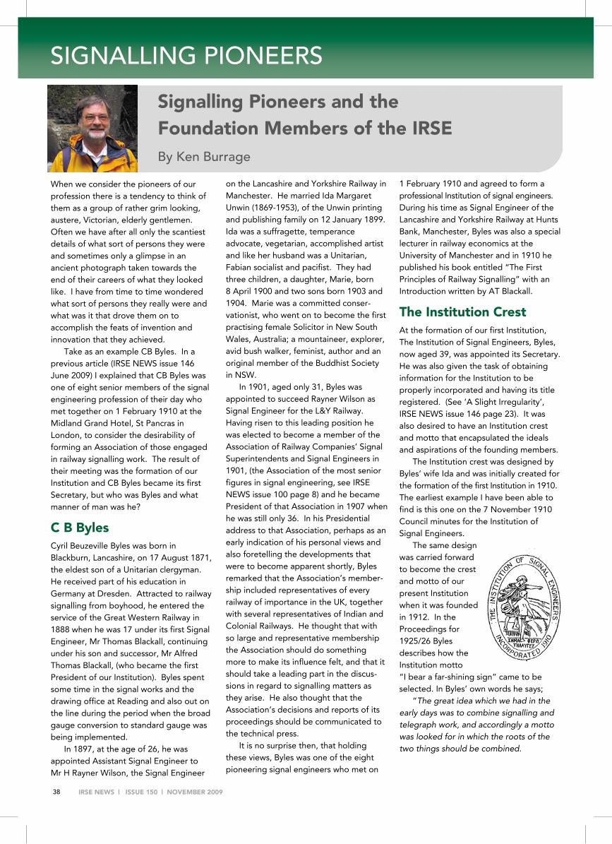
IRSE NEWS | ISSUE 150 | NOVEMBER 2009 38
SIGNALLING PIONEERS
When we consider the pioneers of our profession there is a tendency to think of them as a group of rather grim looking, austere, Victorian, elderly gentlemen. Often we have after all only the scantiest details of what sort of persons they were and sometimes only a glimpse in an ancient photograph taken towards the end of their careers of what they looked like. I have from time to time wondered what sort of persons they really were and what was it that drove them on to accomplish the feats of invention and innovation that they achieved.
Take as an example CB Byles. In a previous article (IRSE NEWS issue 146 June 2009) I explained that CB Byles was one of eight senior members of the signal engineering profession of their day who met together on 1 February 1910 at the Midland Grand Hotel, St Pancras in London, to consider the desirability of forming an Association of those engaged in railway signalling work. The result of their meeting was the formation of our Institution and CB Byles became its first Secretary, but who was Byles and what manner of man was he?
C B Byles Cyril Beuzeville Byles was born in Blackburn, Lancashire, on 17 August 1871, the eldest son of a Unitarian clergyman. He received part of his education in Germany at Dresden. Attracted to railway signalling from boyhood, he entered the service of the Great Western Railway in 1888 when he was 17 under its first Signal Engineer, Mr Thomas Blackall, continuing under his son and successor, Mr Alfred Thomas Blackall, (who became the first President of our Institution). Byles spent some time in the signal works and the drawing office at Reading and also out on the line during the period when the broad gauge conversion to standard gauge was being implemented.
In 1897, at the age of 26, he was appointed Assistant Signal Engineer to Mr H Rayner Wilson, the Signal Engineer
on the Lancashire and Yorkshire Railway in Manchester. He married Ida Margaret Unwin (1869-1953), of the Unwin printing and publishing family on 12 January 1899. Ida was a suffragette, temperance advocate, vegetarian, accomplished artist and like her husband was a Unitarian, Fabian socialist and pacifist. They had three children, a daughter, Marie, born 8 April 1900 and two sons born 1903 and 1904. Marie was a committed conser-vationist, who went on to become the first practising female Solicitor in New South Wales, Australia; a mountaineer, explorer, avid bush walker, feminist, author and an original member of the Buddhist Society in NSW.
In 1901, aged only 31, Byles was appointed to succeed Rayner Wilson as Signal Engineer for the L&Y Railway. Having risen to this leading position he was elected to become a member of the Association of Railway Companies’ Signal Superintendents and Signal Engineers in 1901, (the Association of the most senior figures in signal engineering, see IRSE NEWS issue 100 page 8) and he became President of that Association in 1907 when he was still only 36. In his Presidential address to that Association, perhaps as an early indication of his personal views and also foretelling the developments that were to become apparent shortly, Byles remarked that the Association’s member-ship included representatives of every railway of importance in the UK, together with several representatives of Indian and Colonial Railways. He thought that with so large and representative membership the Association should do something more to make its influence felt, and that it should take a leading part in the discus-sions in regard to signalling matters as they arise. He also thought that the Association’s decisions and reports of its proceedings should be communicated to the technical press.
It is no surprise then, that holding these views, Byles was one of the eight pioneering signal engineers who met on
1 February 1910 and agreed to form a professional Institution of signal engineers. During his time as Signal Engineer of the Lancashire and Yorkshire Railway at Hunts Bank, Manchester, Byles was also a special lecturer in railway economics at the University of Manchester and in 1910 he published his book entitled “The First Principles of Railway Signalling” with an Introduction written by AT Blackall.
The Institution Crest At the formation of our first Institution, The Institution of Signal Engineers, Byles, now aged 39, was appointed its Secretary. He was also given the task of obtaining information for the Institution to be properly incorporated and having its title registered. (See ‘A Slight Irregularity’, IRSE NEWS issue 146 page 23). It was also desired to have an Institution crest and motto that encapsulated the ideals and aspirations of the founding members.
The Institution crest was designed by Byles’ wife Ida and was initially created for the formation of the first Institution in 1910. The earliest example I have been able to find is this one on the 7 November 1910 Council minutes for the Institution of Signal Engineers.
The same design was carried forward to become the crest and motto of our present Institution when it was founded in 1912. In the Proceedings for 1925/26 Byles describes how the Institution motto “I bear a far-shining sign” came to be selected. In Byles’ own words he says;
“The great idea which we had in the early days was to combine signalling and telegraph work, and accordingly a motto was looked for in which the roots of the two things should be combined.
Signalling Pioneers and the Foundation Members of the IRSE By Ken Burrage
SIGNALLING PIONEERS

IRSE NEWS | ISSUE 150 | NOVEMBER 2009 39
The motto was also to express some idea of the combined objective of the new Institution. I will give the actual Greek letters below, but in Roman script the motto is ‘Sema phero telauges’. Thus - Sema - A sign, Phero - I bear, and Telauges – far-shining. I bear a far-shining sign (or signal).”
ΣΗΜΑ ΦΕΡΩ ΤΗΛΑΎΓΕΣ
Byles and family emigrate to Australia
In 1911 Byles, now aged 40 relinquished his post on the L&Y Railway, resigned as Secretary of the Institution and took his family with him to Australia having been appointed as a consultant on signalling to the New South Wales Government Railways.
Shortly after his arrival in Australia in 1911 Byles was appointed as Signal Engineer, New South Wales Railways in Sydney, whereupon he energetically set about a complete re-organisation of the Signal Department, establishing an extensive manufacturing and maintenance workshops and training necessary staff.
For the next 18 years he oversaw an extensive programme of resignalling works using the most up-to-date practices of the day including the introduction of automatic signalling based on route signalling principles. Byles introduced double line automatic signalling to the NSW Railways in 1913, first with lower quadrant electro-pneumatic signals and then shortly after with American style upper quadrant signals. Coloured light signals were introduced in connection with the electrification of the Sydney suburban railways in 1926.
Early in Byles’ period of office miniature electric train staff instruments were introduced on many new single lines instead of the tablet and large electric train staff instruments used previously.
He introduced standard types of mechanical interlocking machines to replace many of the original McKenzie & Holland interlockings. Also standard types of power interlocking machines using the ‘pistol grip’ slide type levers based on the GRS pattern were introduced at many locations in the Sydney metropolitan area during the electrification period of the 1920s. However towards the close of 1929 his health began to fail and he retired from the railway aged only 58.
After leaving for Australia in 1911 Byles did not return to England until after his retirement. He was made a member of the IRSE on 31 March 1913 after its re-constitution in 1912 and remained an IRSE member until his death. He was also present at the inaugural meeting of the IRSE Australasian section on 14 November 1947 at which he reminisced on the formation of the original Institution. He said,
“In the month of February, 1910, the first meeting was held at St Pancras station, London, with a view to forming an Institution of Railway Signal Engineers. Co-ordination was a great word in those days, and the signal engineers felt like spreading their wings to cover a wider field. In those days signalling and tele-graphs were in separate departments. We needed an Institution where discussion would enable members to speak openly about their work and the problems associated with the control of traffic movements. This led to the formation of the English Institution.”
He went on to say, “The first president was AT Blackall,
Signal Engineer, Great Western Railway, and when I reminded him that a Presidential Address was necessary he replied he had neither the time nor the inclination to prepare one, so ‘Young Byles’, as I was called, had to write the inaugural address!”
A humane and cultured man, an academic and a good administrator, Byles was nevertheless a strict disciplinarian and a man of extraordinarily methodical and abstemious habits, passionately devoted to the cause of temperance reform.
Throughout his time in New South Wales he lived in the Sydney suburb of Beecroft. He was fond of gardening and upon his death on 19 November 1952 aged 81 bequeathed most of his lands at Beecroft, covering several acres, to the local Council for public recreation. His was a distinguished career, marked by great strength of purpose and professional skill. It left a lasting impression, not only on the signalling practice of the era in New South Wales but also on that of the other Australian States and in New Zealand where evidence of his progressive spirit could be seen as well. His name continues to be commemorated today in the Australasian Section’s Byles and Calcutt Award. (See forthcoming article).
Unfortunately it has not been possible to locate a photograph of Cyril Byles but photographs of his wife Ida, the designer of the Institution’s crest, and of his daughter Marie, the first female practising Solicitor in NSW, have been found.
In further articles in this series I hope also to explore the lives and careers of the seven Foundation Members of the IRSE, namely
Wilfred Cosens Acfield, Signal Super-intendent, Midland Railway, Derby;
Alfred Thomas Blackall, Signal Engineer, Great Western Railway, Reading;
Charles Dutton, Signal Superintendent, LB&SC Railway, New Cross, London;
Harold William Firth, Electrical Engineer, GE Railway, Liverpool Street, London;
Robert JS Insell, Chief Assistant Signal Engineer, GW Railway, Reading;
Arthur Henry Johnson, Signal and Telegraph Engineer, L&SW Railway, Wimbledon, London;
Josiah Sayers, Telegraph Super-intendent, Midland Railway, Derby.
Acknowledgments
IRSE Proceedings and Council minutes Fifty Years of Railway Signalling by OS Nock.
Ida Byles (nee Unwin) Designer of the IRSE crest
Marie Byles Daughter of Cyril and Ida
Byles

IRSE NEWS | ISSUE 150 | NOVEMBER 2009 40
FEEDBACK Dear Editors
Hixon Level Crossing Accident, 6 January 1968
After this terrible accident, Ted Rogers remitted various units within the BRB S&T Dept to undertake activities associated with its aftermath. One item was the need to respond to a large amount of correspondence from the public. This task fell to Basil Grose, with me as his assistant.
The mail broadly divided into three types. These were:
Hateful / obscene – “You murdering swine…” etc;
Proposed solutions, worthy of follow-up;
Proposed solutions not worthy of follow-up. We quickly set up a reply strategy and prepared a small number of “standard replies” which covered the large majority of the letters.
The point of this “memoir” is to pass on some of the more bizarre suggestions Basil and I had to handle. After such a ghastly accident there was very little to be light-hearted about, but in retrospect, it seems worth circulating these ideas, not only in the context of Hixon, but as an insight to the thinking processes of some people.
Older members may recall the need for BR to make savings in the 1960s/70s, as well as the heart-searching about the introduction of automatic level crossings (aimed at substantially reducing the number of crossing keepers, often on a 3-shift basis). The heart-searching arose from the fact that, for efficient operation, many trains would be inside their braking point if a crossing were obstructed, as the crossings had no signal protection.
Thus the system finally adopted provided roadside telephones intended for road users if they had an unusual or slow load. The rest, as they say, is history. (You may like to look at www.railwaysarchive.co.uk, a goldmine of information including the full Hixon Inquiry report.)
SOME PUBLIC SUGGESTIONS. (On reading my first draft of this, both Basil Grose and Tom Craig very kindly added to my own memories. This is a compilation of all our experiences.)
Many of these introduced ideas that had been considered but abandoned, while others failed to appreciate the lack of braking distance available. These were replied to with a brief, polite explanation why the suggestion was not practical
A few showed some promise, and Basil visited these writers at their homes for further discussion, but in the end, none was found worth development. However, a very small number showed such vivid imagination coupled with a complete lack of knowledge of the laws of physics that they became truly memorable. It is these I would like to share with you.
Evasion This proposal involved fitting a left-handed turnout “just before the crossing” that, in the event of a train approaching it while obstructed, would “throw to reverse” and divert the train onto a length of circular track, thus allowing it to go round and round until it stopped.
Extra braking Here, the approaches to the crossing would be fitted “for a couple of hundred yards” with Dowty retarders (as often used in
hump marshalling yards at the time). Under normal conditions, the retarders are free to be depressed as wheels pass over them. But if a crossing is detected as obstructed on the approach of a train, hydraulic fluid at high pressure is applied to the retarders, having a powerful braking effect on the train.
We did not conduct any noise tests on trains passing over Dowty units, either relaxed or under pressure, but sat pondering the effects on nearby housing!
Extreme braking It was proposed a large hook be installed in the 4-foot “at a suitable distance from the crossing” and in the event of the crossing being obstructed, it would rise up and catch the leading axle of the train. The writer did not explain what material would connect the hook to the ground. We supposed it must have been based on aircraft carrier arresters. Not too good for coffee or soup containers.
Improved visibility This required a “trip” in the track some distance before the crossing, and all traction units to be fitted with large magnifying glasses which swung down in front of the driver on passing over the “trip”, so that he could see if the crossing was clear or not. The proposer did not mention the need to straighten the railway for a sufficient distance to ensure a clear view of the crossing, where necessary. (Basil and I wondered whether a bible rather than a mirror might be more appropriate.)
Preventing obstructions We received three suggestions in this category. The first would have put quite a design load on the Highways Engineer as it involved revising the roadway surface so that it ran sharply downhill in both directions. We tried drawing this, and ended up with something not unlike a sketch by Escher!
The second suggestion had the crossing’s roadway fitted with rollers, normally locked, but set free during the approach of a train. We presumed the intention was to allow a vehicle on the crossing to be pushed clear. However, since the pusher’s feet would also be on the (now free) rollers, the effort would be frustrated.
Finally, something akin to a short, wide travelator was offered. This appeared to run continuously, so that any vehicle becoming “stationary” on the crossing would automatically be carried clear. No further technical details were included, so we were left to consider how the five or more sections were to be connected or driven to take account of the gaps needed at each rail. Maintenance and power consumption both seemed rather expensive.
Train detection This suggestion concerned itself only with detecting trains, with no proposals as to what to do with the information. We did not pursue it since track circuits and treadles were readily available to us. The “invention” though “was a naval secret” which turned out to be detection of the heat of a ship’s funnel. This was also the year of the demise of steam traction on BR
An odd-ball We never really found out why this letter was directed to us, as it had nothing to do with level crossings, but was about passenger safety. The handwriting indicated it was possibly from a frail, elderly lady.
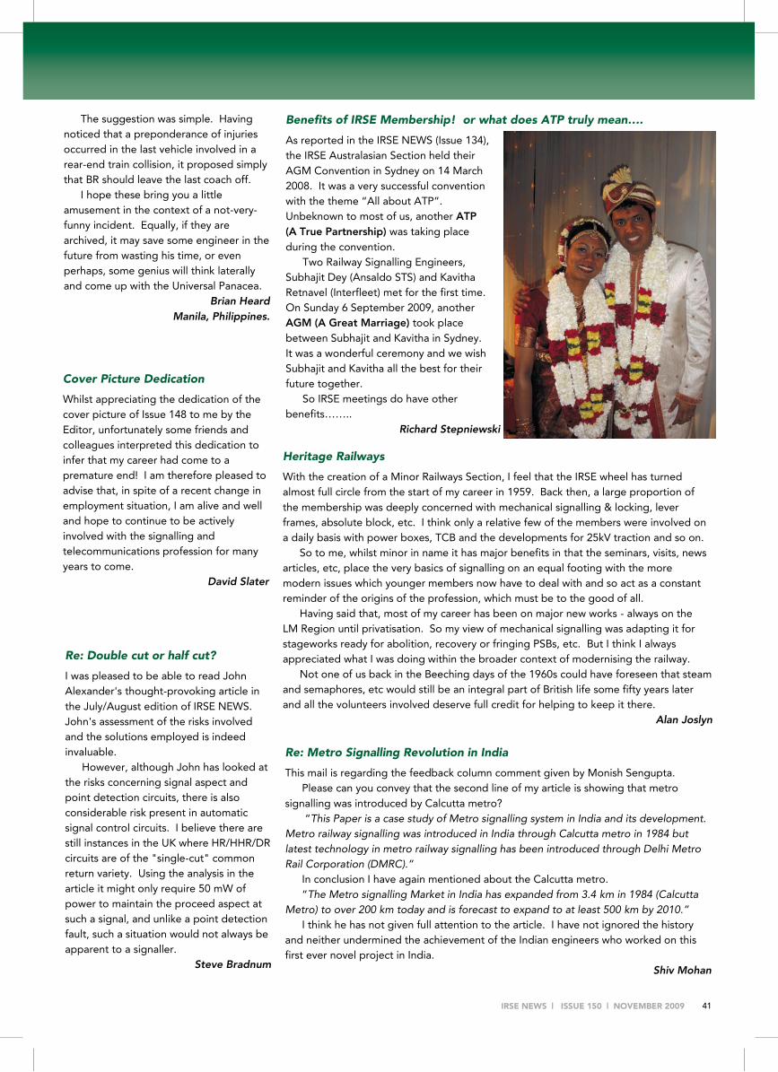
IRSE NEWS | ISSUE 150 | NOVEMBER 2009 41
Cover Picture Dedication
Whilst appreciating the dedication of the cover picture of Issue 148 to me by the Editor, unfortunately some friends and colleagues interpreted this dedication to infer that my career had come to a premature end! I am therefore pleased to advise that, in spite of a recent change in employment situation, I am alive and well and hope to continue to be actively involved with the signalling and telecommunications profession for many years to come.
David Slater
Heritage Railways
With the creation of a Minor Railways Section, I feel that the IRSE wheel has turned almost full circle from the start of my career in 1959. Back then, a large proportion of the membership was deeply concerned with mechanical signalling & locking, lever frames, absolute block, etc. I think only a relative few of the members were involved on a daily basis with power boxes, TCB and the developments for 25kV traction and so on.
So to me, whilst minor in name it has major benefits in that the seminars, visits, news articles, etc, place the very basics of signalling on an equal footing with the more modern issues which younger members now have to deal with and so act as a constant reminder of the origins of the profession, which must be to the good of all.
Having said that, most of my career has been on major new works - always on the LM Region until privatisation. So my view of mechanical signalling was adapting it for stageworks ready for abolition, recovery or fringing PSBs, etc. But I think I always appreciated what I was doing within the broader context of modernising the railway.
Not one of us back in the Beeching days of the 1960s could have foreseen that steam and semaphores, etc would still be an integral part of British life some fifty years later and all the volunteers involved deserve full credit for helping to keep it there.
Alan Joslyn
The suggestion was simple. Having noticed that a preponderance of injuries occurred in the last vehicle involved in a rear-end train collision, it proposed simply that BR should leave the last coach off.
I hope these bring you a little amusement in the context of a not-very-funny incident. Equally, if they are archived, it may save some engineer in the future from wasting his time, or even perhaps, some genius will think laterally and come up with the Universal Panacea.
Brian Heard Manila, Philippines.
Benefits of IRSE Membership! or what does ATP truly mean….
As reported in the IRSE NEWS (Issue 134), the IRSE Australasian Section held their AGM Convention in Sydney on 14 March 2008. It was a very successful convention with the theme “All about ATP”. Unbeknown to most of us, another ATP (A True Partnership) was taking place during the convention.
Two Railway Signalling Engineers, Subhajit Dey (Ansaldo STS) and Kavitha Retnavel (Interfleet) met for the first time. On Sunday 6 September 2009, another AGM (A Great Marriage) took place between Subhajit and Kavitha in Sydney. It was a wonderful ceremony and we wish Subhajit and Kavitha all the best for their future together.
So IRSE meetings do have other benefits……..
Richard Stepniewski
Re: Double cut or half cut?
I was pleased to be able to read John Alexander's thought-provoking article in the July/August edition of IRSE NEWS. John's assessment of the risks involved and the solutions employed is indeed invaluable.
However, although John has looked at the risks concerning signal aspect and point detection circuits, there is also considerable risk present in automatic signal control circuits. I believe there are still instances in the UK where HR/HHR/DR circuits are of the "single-cut" common return variety. Using the analysis in the article it might only require 50 mW of power to maintain the proceed aspect at such a signal, and unlike a point detection fault, such a situation would not always be apparent to a signaller.
Steve Bradnum
Re: Metro Signalling Revolution in India This mail is regarding the feedback column comment given by Monish Sengupta.
Please can you convey that the second line of my article is showing that metro signalling was introduced by Calcutta metro?
“This Paper is a case study of Metro signalling system in India and its development. Metro railway signalling was introduced in India through Calcutta metro in 1984 but latest technology in metro railway signalling has been introduced through Delhi Metro Rail Corporation (DMRC).”
In conclusion I have again mentioned about the Calcutta metro. “The Metro signalling Market in India has expanded from 3.4 km in 1984 (Calcutta
Metro) to over 200 km today and is forecast to expand to at least 500 km by 2010.” I think he has not given full attention to the article. I have not ignored the history
and neither undermined the achievement of the Indian engineers who worked on this first ever novel project in India.
Shiv Mohan

MEMBERSHIP
IRSE NEWS | ISSUE 150 | NOVEMBER 2009 38
ELECTIONS We extend a warm welcome to the following newly-elected members:
Fellow
Chaudhary K Secy. Railway Board Dwivedi A K N E Railway (UP) Pal D R South Eastern Railway Theru G O Southern Railway
Member
Bulatov A Latvian Railway Doomernik J Lloyd's Register Nederland Kruger D Hatch Mitchell M Thales Rispens J Railwaysafe Saiyad A Infotech Enterprises Straver P J DHV West S Westinghouse Rail Systems
Associate Member
Eijsink W ProRail, Signalling Dept. Karim M Network Rail Lee P Babcock Rail Parashar V SERCO Middle East Schrik E Movares Nederland Smalley J A Network Rail
Accredited Technician
Bangash M LUL Nominee SSL Coleman G I Volker Rail Signalling Gregory C C Babcock Rail Haigh B Westinghouse Maguire D Network Rail Matthews A Kelly ITS McNicol R Atkins Rail Moyston‑Johnson M K Milan Engineers Nyoni I LUL Nominee SSL
Associate
Anshuman A Patni Computer System Chandra Singh Rawat S Ansaldo‑STS Copley A P Mid-Hants and Dean Forest Railways Dasar Narayan V K Ansaldo‑sts Enkt R Strukton Rail Gupta R Ansaldo‑STS Hartley A J Babcock Rail Hayden A London Underground Layole J M U Siemens Transportation Systems Pandey J Delhi Metro Rail Corp. Pugh B Westinghouse Rail Systems Ramos Martínez A Network Rail Redfern J Kidde Products Reeve L H Thales Rail Signalling Solutions Sampson C L Thales Rail Tiwari A K Delhi Metro Rail Corp. Von Metz L HM Railway Inspectorate
Student
Bradford J Ansaldo‑STS Popplewell N TransAdelaide
TRANSFERS Member to Fellow
Martell P Amey
Associate to Member
Marshall J P Sitec
Associate to Associate Member
Helliwell D L Amey Karim I Western Railway
Student to Associate Member
Kemp L R Amey Consulting Westerman D Network Rail
Student to Associate
Chiu W C London Underground
RESIGNATIONS Allen R Balderston C Barley S Beere BJ Creighton SA Frej I Galloway D Jones ER Langan PR Loots G Rogerson K Tunnicliffe D
Since 25 April 2009, 193 members were struck off the database for non-payment of subscriptions; 52 of whom were new members who had not paid their first subscriptions.
Engineering Council UK Registrations The following members have been recommended for
Engineering Council UK registration:
Dade DW Final Stage EngTech Gammon R Final Stage IEng Kumar V Final Stage CEng Markham I Final Stage CEng Moir SJ Final Stage CEng Rollings EC Final Stage CEng
Current Membership Total is 4437