Embed Size (px)
Citation preview
GROUND MOUNT
INSTALLATION MANUAL
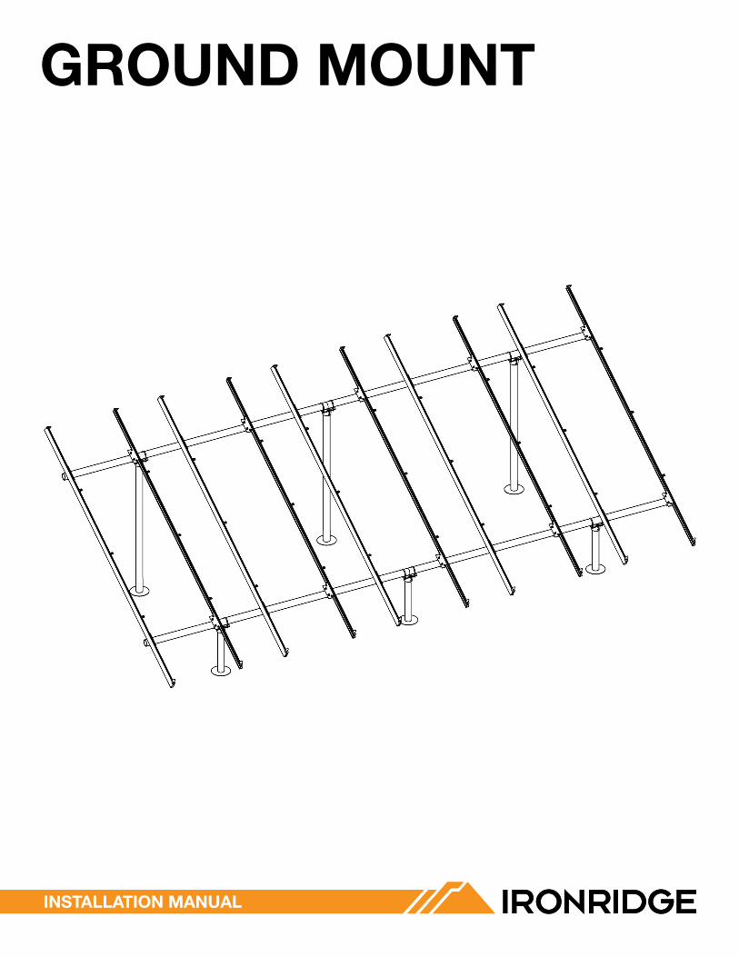
CONTeNTS
GROUND MOUNT INSTALLATION MANUAL - 1© 2016 IRONRIDGE, INC. VERSION 1.10
DISCLAIMeR 1RATINGS 2MARKINGS 2CHeCKLIST 31. BUILD BASe 42. CONNeCT SUBSTRUCTURe 43. PLACe RAILS 54. SeCURe LUGS 55. SeCURe MODULeS 6eLeCTRICAL DIAGRAM 7DIAGONAL BRACeS (OPTIONAL) 8eND CAPS 8WIRe CLIPS 8SPLICING CROSS PIPe 9MICROINVeRTeR KITS 10SYSTeMS USING eNPHASe MICROINVeRTeRS 10FRAMeLeSS MODULe KITS 10MODULe COMPATIBILITY 11WARRANTY 12
DISCLAIMeR
This manual describes the proper installation procedures and provides necessary standards required for product reliability and warranty. All installers must thoroughly read this manual and have a clear understanding of the installation procedures prior to installation. Failure to follow these guidelines may result in property damage, bodily injury or even death.
IT IS THe INSTALLeR’S ReSPONSIBILITY TO:
• Ensure that the installation is completed by a licensed solar professional. All electrical installation and procedures should be conducted by a licensed and bonded electrician or solar contractor. Routine maintenance of a module or panel shall not involve breaking or disturbing the bonding path of the system.
• Comply with all applicable local or national building and fire codes, including any that may supersede this manual.• Ensure all products are appropriate for the installation, environment, and array under the site’s loading conditions.• Use only IronRidge parts or parts recommended by IronRidge; substituting parts may void any applicable warranty.• Review the Design Assistant, Engineering Design Guide, and Certification Letters to confirm design specifications.• Comply with all applicable fire codes including, but not limited to, keeping walkways clear and avoiding obstacles.• Ensure provided information is accurate. Issues resulting from inaccurate information are the installer’s responsibility.• Validate foundation parameters prior to installation, as a local geotechnical report may be required to assess ground
conditions. We recommend consulting with a local engineer familiar with local regulations and build site requirements, including soil conditions, terrain and load criteria. All parameters may impact foundation requirements.
• Ensure safe installation of all electrical aspects of the array. All electrical installation and procedures should be conducted by a licensed and bonded electrician or solar contractor. All work must comply with national, state and local installation procedures, product and safety standards.
• Ensure provided information is accurate. Issues resulting from inaccurate information are the installers’ responsibility.• Ensure bare copper grounding wire does not contact aluminum and zinc-plated steel components, to prevent risk of
galvanic corrosion.• If loose components or loose fasteners are found during periodic inspection, re-tighten immediately. If corrosion is
found, replace affected components immediately.• Provide an appropriate method of direct-to-earth grounding according to the latest edition of the National Electrical
Code, including NEC 250: Grounding and Bonding, and NEC 690: Solar Photovoltaic Systems.• Disconnect AC power before servicing or removing microinverters and power optimizers.
GROUND MOUNT INSTALLATION MANUAL - 2© 2016 IRONRIDGE, INC. VERSION 1.10
RATINGS
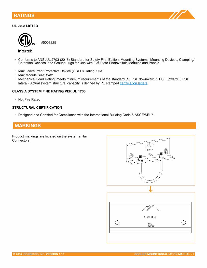
MARKINGS
Product markings are located on the system’s Rail Connectors.
UL 2703 LISTeD
• Conforms to ANSI/UL 2703 (2015) Standard for Safety First Edition: Mounting Systems, Mounting Devices, Clamping/Retention Devices, and Ground Lugs for Use with Flat-Plate Photovoltaic Modules and Panels
• Max Overcurrent Protective Device (OCPD) Rating: 25A• Max Module Size: 24ft²• Mechanical Load Rating: meets minimum requirements of the standard (10 PSF downward, 5 PSF upward, 5 PSF
lateral). Actual system structural capacity is defined by PE stamped certification letters.
CLASS A SYSTeM FIRe RATING PeR UL 1703
• Not Fire Rated
STRUCTURAL CeRTIFICATION
• Designed and Certified for Compliance with the International Building Code & ASCE/SEI-7
#5003225

GROUND MOUNT INSTALLATION MANUAL - 3© 2016 IRONRIDGE, INC. VERSION 1.10
CHeCKLIST
IRONRIDGe COMPONeNTS
XR1000 Rail Rail Connector
Top Cap UFO
Diagonal Brace
End Cap Wire Clip
Stopper Sleeve
PRe-INSTALLATION
☐ Verify module compatibility. See Page 11 for info.
☐ Purchase 2” or 3” ASTM A53 Grade B Schedule 40 Pipe, galvanized to a min of ASTM A653 G90 or ASTM A123 G35, or 2” or 3” Allied Mechanical Tubing with Gatorshield or FlowCoat Zinc coating (ASTM A1057).
TOOLS ReQUIReD
☐ Post Hole Digger or Powered Auger
☐ Socket Drive (7/16”, 9/16”, and 1/2” Sockets)
☐ Torque Wrenches (0-240 in-lbs and 10-40 ft-lbs)
☐ Transit, String Line, or Laser Level
☐ 3/8” Allen Head
TORQUe VALUeS
☐ Top Cap Set Screws (3/8” Allen Head)
Schedule 40 Pipe: 20 ft-lbs
2” Allied Mechanical Tubing: 11 ft-lbs
3” Allied Mechanical Tubing: 16 ft-lbs
☐ Top Cap U-Bolt Nuts (9/16” Socket): 15 ft-lbs
☐ Rail Connector Bracket Nuts (9/16” Socket): 21 ft-lbs
☐ Rail Connector U-Bolt Nuts (9/16” Socket): 60 in-lbs
☐ Grounding Lug Nuts (7/16” Socket): 80 in-lbs
☐ Grounding Lug Terminal Screws (7/16 Socket): 20 in-lbs
☐ Universal Fastening Objects (7/16” Socket): 80 in-lbs
☐ Diagonal Brace Set Screws (1/2” Socket): 15 ft-lbs
☐ Diagonal Brace Bolts (1/2” Socket): 40 ft-lbs
☐ MLPE Kit Nuts (7/16” Socket): 80 in-lbs
☐ Frameless Module Kit Nuts (7/16” Socket): 80 in-lbs
í If using previous version of: Integrated Grounding Mid Clamps, Grounding Lug, end Clamps, and expansion Joints please refer to Alternate Components Addendum version 1.0
Grounding Lug
Microinverter Kit
Frameless Module Kit
GROUND MOUNT INSTALLATION MANUAL - 4© 2016 IRONRIDGE, INC. VERSION 1.10
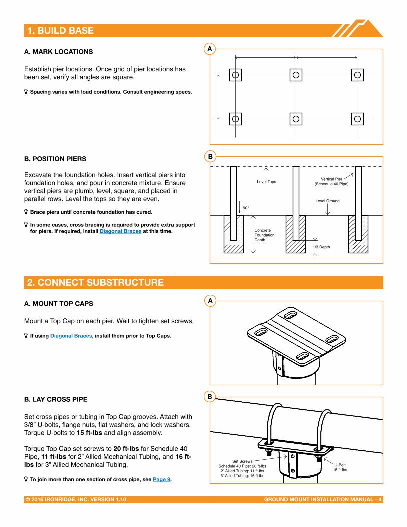
1. BUILD BASe
A. MARK LOCATIONS
Establish pier locations. Once grid of pier locations has been set, verify all angles are square.
í Spacing varies with load conditions. Consult engineering specs.
B. POSITION PIeRS
Excavate the foundation holes. Insert vertical piers into foundation holes, and pour in concrete mixture. Ensure vertical piers are plumb, level, square, and placed in parallel rows. Level the tops so they are even.
í Brace piers until concrete foundation has cured.
í In some cases, cross bracing is required to provide extra support for piers. If required, install Diagonal Braces at this time.
A. MOUNT TOP CAPS
Mount a Top Cap on each pier. Wait to tighten set screws.
í If using Diagonal Braces, install them prior to Top Caps.
B. LAY CROSS PIPe
Set cross pipes or tubing in Top Cap grooves. Attach with 3/8” U-bolts, flange nuts, flat washers, and lock washers. Torque U-bolts to 15 ft-lbs and align assembly.
Torque Top Cap set screws to 20 ft-lbs for Schedule 40 Pipe, 11 ft-lbs for 2” Allied Mechanical Tubing, and 16 ft-lbs for 3” Allied Mechanical Tubing.
í To join more than one section of cross pipe, see Page 9.
2. CONNeCT SUBSTRUCTURe
A
B
A
B
Level Tops Vertical Pier(Schedule 40 Pipe)
Level Ground90°
U-Bolt15 ft-lbs
Set ScrewsSchedule 40 Pipe: 20 ft-lbs2” Allied Tubing: 11 ft-lbs3” Allied Tubing: 16 ft-lbs
1/3 Depth
ConcreteFoundation Depth
GROUND MOUNT INSTALLATION MANUAL - 5© 2016 IRONRIDGE, INC. VERSION 1.10
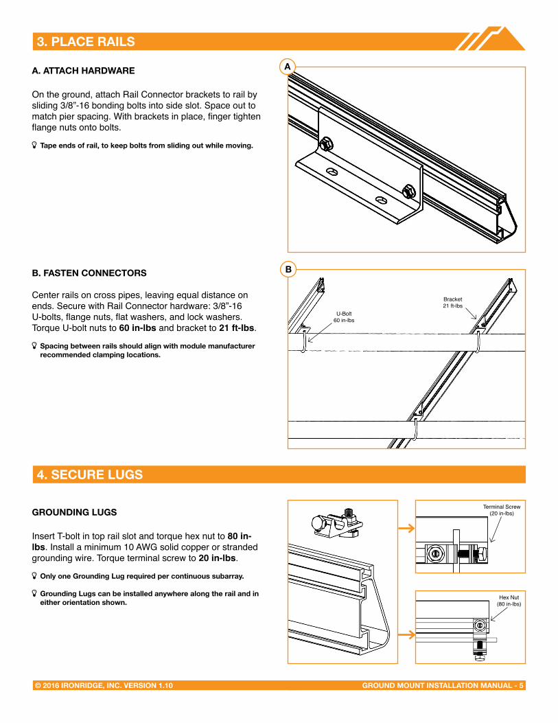
3. PLACe RAILS
A. ATTACH HARDWARe
On the ground, attach Rail Connector brackets to rail by sliding 3/8”-16 bonding bolts into side slot. Space out to match pier spacing. With brackets in place, finger tighten flange nuts onto bolts.
í Tape ends of rail, to keep bolts from sliding out while moving.
B. FASTeN CONNeCTORS
Center rails on cross pipes, leaving equal distance on ends. Secure with Rail Connector hardware: 3/8”-16 U-bolts, flange nuts, flat washers, and lock washers. Torque U-bolt nuts to 60 in-lbs and bracket to 21 ft-lbs.
í Spacing between rails should align with module manufacturer recommended clamping locations.
GROUNDING LUGS
Insert T-bolt in top rail slot and torque hex nut to 80 in-lbs. Install a minimum 10 AWG solid copper or stranded grounding wire. Torque terminal screw to 20 in-lbs.
í Only one Grounding Lug required per continuous subarray.
í Grounding Lugs can be installed anywhere along the rail and ineither orientation shown.
4. SeCURe LUGS
A
B
U-Bolt60 in-lbs
Bracket21 ft-lbs
Hex Nut(84 in-lbs)
Terminal Screw(20 in-lbs)
Hex Nut(80 in-lbs)
GROUND MOUNT INSTALLATION MANUAL - 6© 2016 IRONRIDGE, INC. VERSION 1.10
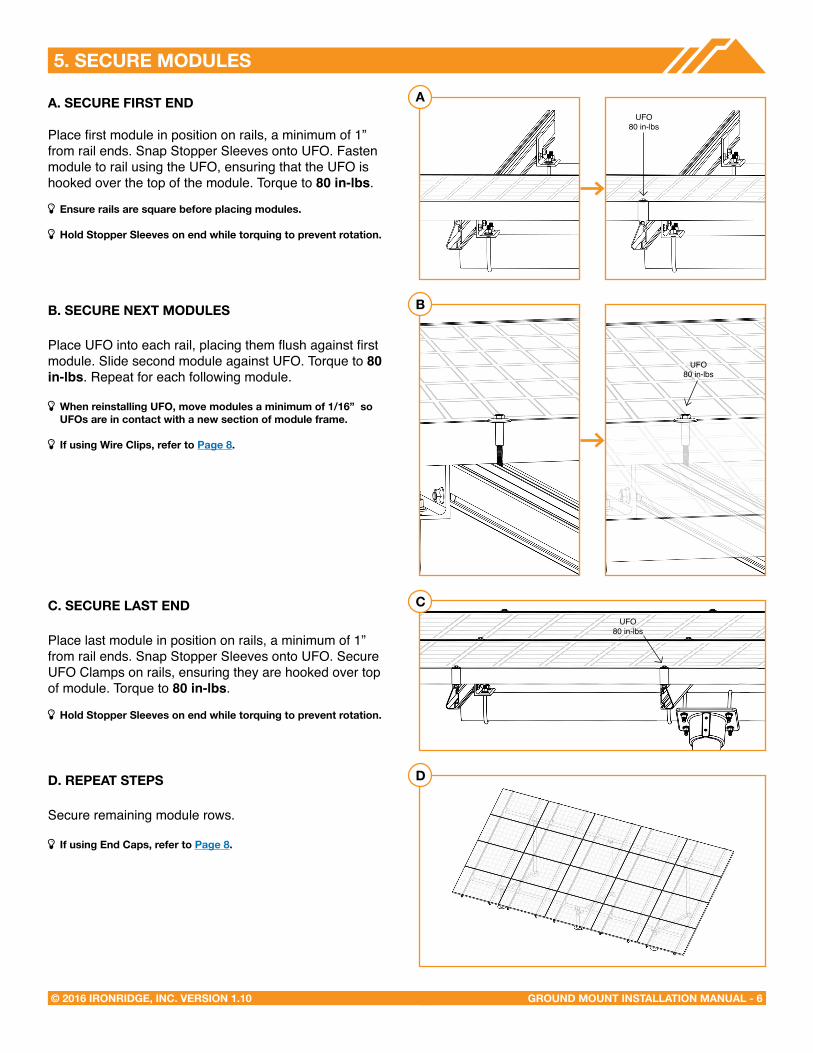
5. SeCURe MODULeS
A. SeCURe FIRST eND
Place first module in position on rails, a minimum of 1” from rail ends. Snap Stopper Sleeves onto UFO. Fasten module to rail using the UFO, ensuring that the UFO is hooked over the top of the module. Torque to 80 in-lbs.
í ensure rails are square before placing modules.
í Hold Stopper Sleeves on end while torquing to prevent rotation.
B. SeCURe NeXT MODULeS
Place UFO into each rail, placing them flush against first module. Slide second module against UFO. Torque to 80 in-lbs. Repeat for each following module.
í When reinstalling UFO, move modules a minimum of 1/16” so UFOs are in contact with a new section of module frame.
í If using Wire Clips, refer to Page 8.
C. SeCURe LAST eND
Place last module in position on rails, a minimum of 1” from rail ends. Snap Stopper Sleeves onto UFO. Secure UFO Clamps on rails, ensuring they are hooked over top of module. Torque to 80 in-lbs.
í Hold Stopper Sleeves on end while torquing to prevent rotation.
D. RePeAT STePS
Secure remaining module rows.
í If using end Caps, refer to Page 8.
A
B
C
D
UFO80 in-lbs
UFO80 in-lbs
UFO80 in-lbs
GROUND MOUNT INSTALLATION MANUAL - 7© 2016 IRONRIDGE, INC. VERSION 1.10
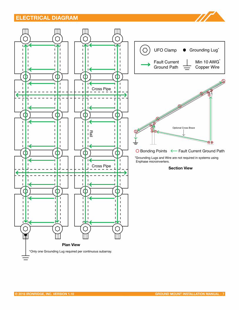
eLeCTRICAL DIAGRAM
UFO Clamp Grounding Lug
Min 10 AWGCopper Wire
Fault Current Ground Path
Bonding Points Fault Current Ground PathGrounding Lugs and Wire are not required in systems using Enphase microinverters.
*
*
*
Section View
Plan View
Optional Cross Brace
Only one Grounding Lug required per continuous subarray.*
Cross Pipe
Rail
Cross Pipe
GROUND MOUNT INSTALLATION MANUAL - 8© 2016 IRONRIDGE, INC. VERSION 1.10
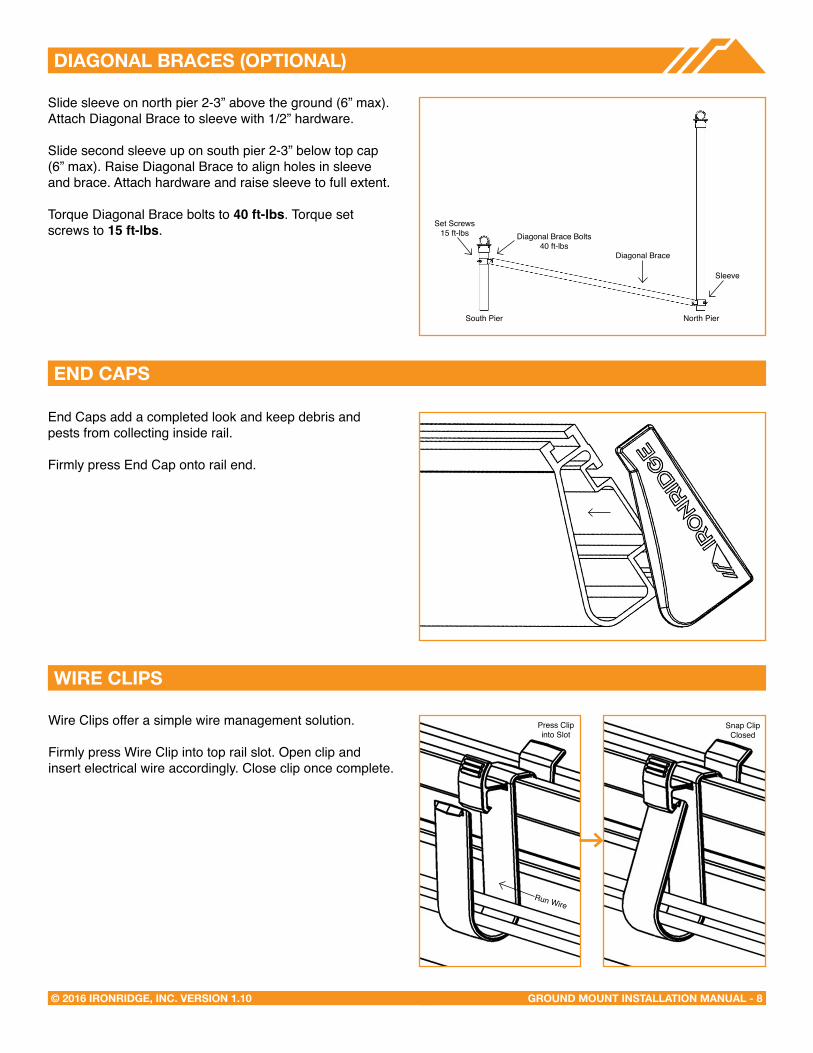
DIAGONAL BRACeS (OPTIONAL)
Slide sleeve on north pier 2-3” above the ground (6” max).Attach Diagonal Brace to sleeve with 1/2” hardware.
Slide second sleeve up on south pier 2-3” below top cap (6” max). Raise Diagonal Brace to align holes in sleeve and brace. Attach hardware and raise sleeve to full extent.
Torque Diagonal Brace bolts to 40 ft-lbs. Torque set screws to 15 ft-lbs.
eND CAPS
WIRe CLIPS
End Caps add a completed look and keep debris and pests from collecting inside rail.
Firmly press End Cap onto rail end.
Wire Clips offer a simple wire management solution.
Firmly press Wire Clip into top rail slot. Open clip and insert electrical wire accordingly. Close clip once complete.
South Pier North Pier
Diagonal Brace
Diagonal Brace Bolts40 ft-lbs
Set Screws15 ft-lbs
Sleeve
Press Clip into Slot
Run Wire
Snap Clip Closed
GROUND MOUNT INSTALLATION MANUAL - 9© 2016 IRONRIDGE, INC. VERSION 1.10
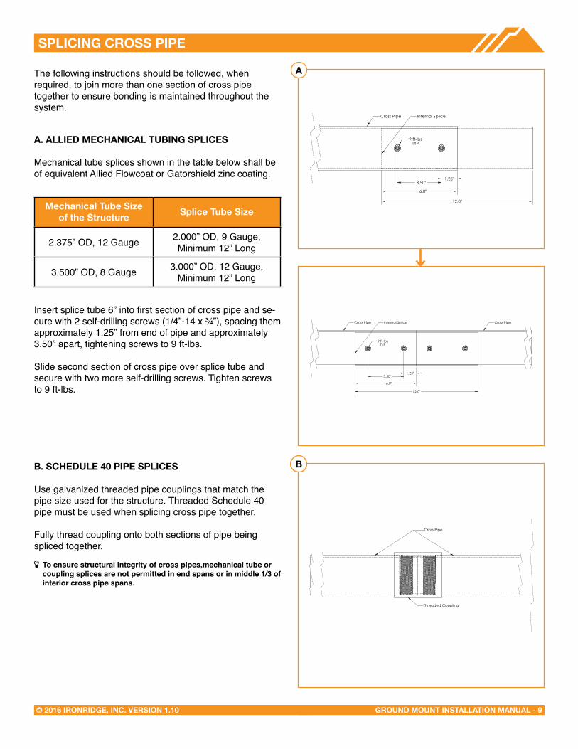
SPLICING CROSS PIPe
The following instructions should be followed, when required, to join more than one section of cross pipe together to ensure bonding is maintained throughout the system.
A. ALLIeD MeCHANICAL TUBING SPLICeS
Mechanical tube splices shown in the table below shall be of equivalent Allied Flowcoat or Gatorshield zinc coating.
Insert splice tube 6” into first section of cross pipe and se-cure with 2 self-drilling screws (1/4”-14 x ¾”), spacing them approximately 1.25” from end of pipe and approximately 3.50” apart, tightening screws to 9 ft-lbs.
Slide second section of cross pipe over splice tube and secure with two more self-drilling screws. Tighten screws to 9 ft-lbs.
B. SCHeDULe 40 PIPe SPLICeS
Use galvanized threaded pipe couplings that match the pipe size used for the structure. Threaded Schedule 40 pipe must be used when splicing cross pipe together.
Fully thread coupling onto both sections of pipe being spliced together.
í To ensure structural integrity of cross pipes,mechanical tube or coupling splices are not permitted in end spans or in middle 1/3 of interior cross pipe spans.
Mechanical Tube Size of the Structure Splice Tube Size
2.375” OD, 12 Gauge 2.000” OD, 9 Gauge, Minimum 12” Long
3.500” OD, 8 Gauge 3.000” OD, 12 Gauge, Minimum 12” Long
12.0"
6.0"
1.25" 3.50"
Cross Pipe Internal Splice
9 ft-lbsTYP
Cross Pipe
Threaded Coupling
12.0"
6.0"
1.25" 3.50"
Cross Pipe Internal Splice
9 ft-lbsTYP
Cross Pipe
A
B

GROUND MOUNT INSTALLATION MANUAL - 10© 2016 IRONRIDGE, INC. VERSION 1.10
MICROINVeRTeR KITS
Microinverter Kit(80 in-lbs)
SYSTeMS USING eNPHASe MICROINVeRTeRS
IronRidge systems using approved Enphase products eliminate the need for lay-in lugs and field installed equipment grounding conductors (EGC). This solution meets the requirements of UL 2703 for bonding and grounding and is included in this listing.
The following Enphase products are included in this listing: Microinverters M250-72, M250-60, M215-60, C250-72, and Engage cables ETXX-240, ETXX-208, ETXX-277.
í A minimum of two inverters mounted to the same rail and connected to the same Engage cable are required.
í The microinverters must be used with a maximum 20 A branch rated overcurrent protection device (OCPD).
Use IronRidge's Microinverter Kit to bond compatible microinverters and power optimizers to the racking system.
Insert Microinverter Kit T-bolt into top rail slot. Place compatible microinverter or power optimizer into position and tighten hex nut to 80 in-lbs.
COMPATIBLe PRODUCTS
Enphase - M250-72, M250-60, M215-60, and C250-72Darfon - MIG240, MIG300, G320, G640Solar Edge - P300, P320, P400, P405, P600, P700, P730
FRAMeLeSS MODULe KITS
Insert Frameless Kit T-bolt in top rail slot. Place star washer over T-bolt, allowing it to rest on top of rail. Secure module clamps with a hex nut and torque to 80 in-lbs.
í Tested or evaluated third-party module clamps: • Sunforson silver or black SFS-UTMC-200(B) mid and SFS-
UTEC-200(B) end clamps.• Sunpreme silver or black mid and end clamps with part
numbers 7500105X where X can be 1,5,6 or 7.
í Follow module manufacturer's installation instructions to install the module clamps.
Place Star Washer
Module Clamp(80 in-lbs) One Grounding Lug Per
Continuous Subarray
GROUND MOUNT INSTALLATION MANUAL - 11© 2016 IRONRIDGE, INC. VERSION 1.10
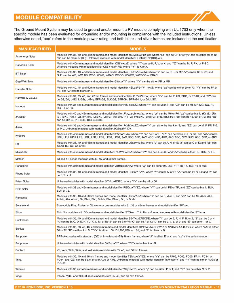
MODULe COMPATIBILITY
The Ground Mount System may be used to ground and/or mount a PV module complying with UL 1703 only when the specific module has been evaluated for grounding and/or mounting in compliance with the included instructions. Unless otherwise noted, “xxx” refers to the module power rating and both black and silver frames are included in the certification.
MANUFACTUReR MODeLS
Astronergy Solar Modules with 35, 40, and 45mm frames and model identifier aaSM66yyPzz-xxx; where “aa” can be CH or A; “yy” can be either 10 or 12; “zz” can be blank or (BL). Unframed modules with model identifier CHSM6610P(DG)-xxx.
Canadian Solar Modules with 40mm frames and model identififer CS6Y-xxxZ; where "Y" can be K, P, V, or X; and ""Z"" can be M, P, PX, or P-SD. Uframed modules with model identifier CS6Y-xxxP-FG; where ""Y"" is K or X.
ET Solar Modules with 35, 40, and 50mm frames and model identifier ET-Y6ZZxxxAA; where "Y" can be P, L, or M; "ZZ" can be 60 or 72; and "AA" can be WB, WW, BB, WBG, WWG, WBAC, WBCO, WWCO, WWBCO or BBAC.
GigaWatt Solar Modules with 40mm frames and model identifier GWxxxYY; where “YY” can be either PB or MB.
Hanwha Solar Modules with 40, 45, and 50mm frames and model identifier HSLaaP6-YY-1-xxxZ; where "aa" can be either 60 or 72; "YY" can be PA or PB; and "Z" can be blank or B.
Hanwha Q CELLS Modules with 32, 35, 40, and 42mm frames and model identifier Q.YY-ZZ-xxx; where "YY" can be PLUS, PRO, or PEAK; and "ZZ" can be G3, G4, L-G2, L-G3y, L-G4y, BFR-G3, BLK-G3, BFR-G4, BFR-G4.1, or G4.1/SC.
Hyundai Modules with 35 and 50mm frames and model identifier HiS-YxxxZZ; where "Y" can be M or S; and "ZZ" can be MI, MF, MG, SG, RI, RG, TI, or TG.
JA SolarModules with 40 and 45mm frames and model identifier JAyyzz-bb-xxx/aa; where “yy” can be M6 or P6; “zz” can be blank, (K), (L), (R), (V), (BK), (FA), (TG), (FA)(R), (L)(BK), (L)(TG), (R)(BK), (R)(TG), (V)(BK), (BK)(TG), or (L)(BK)(TG); “bb” can be 48, 60, or 72; and “aa” can be MP, SI, PR, 3BB, 4BB, 4BB/RE.
Jinko Modules with 35 and 40mm frames and model identifier JKMYxxxZZ; where "Y" can either be blank or S; and "ZZ" can be M, P, PP, P-B, or P-V. Unframed modules with model identifier JKMxxxPP-DV.
Kyocera Modules with 46mm frames and model identifier KYxxxZZ-AA; where "Y" can be D or U; "ZZ" can be blank, GX, or SX; and "AA" can be LPU, LFU, UPU, LPS, LPB, ,LFB, LFBS, LFB2, LPB2, 3AC, 3BC, 3FC, 4AC, 4BC, 4FC, 4UC, 5AC, 5BC, 5FC, 5UC, 6BC, 6FC, or 8BC.
LG Modules with 35, 40, and 46mm frames and model identifier LGxxxy1z-bb; where "y" can be A, N, or S; "z" can be C or K; and "bb" can be A3, B3, G3, C4 or K4.
Mistubishi Modules with 46mm frames and model identifier PV-MYYxxxZZ; where "YY" can be LE or JE; and "ZZ" can be either HD, HD2, or FB.
Motech IM and XS series modules with 40, 45, and 50mm frames.
Panasonic Modules with 35mm frames and model identifier VBHNxxxSAyy; where "yy" can be either 06, 06B, 11, 11B, 15, 15B, 16 or 16B.
Phono Solar Modules with 35, 40, and 45mm frames and model identifier PSxxxY-ZZ/A; where "Y" can be M or P; "ZZ" can be 20 or 24; and "A" can be F, T or U.
Prism Solar Unframed modules with model identifier BiYY-xxxBSTC; where "YY" can be 48 or 60.
REC Solar Modules with 38 and 45mm frames and model identifier RECxxxYYZZ; where “YY” can be M, PE or TP; and “ZZ” can be blank, BLK, SLV, or 72.
Renesola Modules with 35, 40 and 50mm frames and model identifier JCxxxY-ZZ; where "Y" can be F, M or S; and "ZZ" can be Ab, Ab-b, Abh, Abh-b, Abv, Abv-b, Bb, Bb-b, Bbh, Bbh-b, Bbv, Bbv-b, Db, or Db-b.
SolarWorld Sunmodule Plus, Protect or XL mono or poly modules with 31, 33 or 46mm frames and model identifier SW-xxx.
Stion Thin film modules with 35mm frames and model identifier STO-xxx. Thin film unframed modules with model identifier STL-xxx.
SunEdison Modules with 35, 40, and 50mm frames and model identifier SE-YxxxZABCDE; where "Y" can be B, F, H, P, R, or Z; "Z" can be 0 or 4; "A" can be B, C, D, E, H, I, J, K, L, M, or N; "B" can be B or W; "C" can be A or C; "D" can be 3, 7, 8, or 9; and "E" can be 0, 1 or 2.
Suniva Modules with 35, 38, 40, 46, and 50mm frames and model identifiers OPTxxx-AA-B-YYY-Z or MVXxxx-AA-B-YYY-Z; where "AA" is either 60 or 72; "B" is either 4 or 5; "YYY" is either 100,101,700,1B0, or 1B1; and "Z" is blank or B.
Sunpower SPR-A-xx series with standard (G3) or InvisiMount (G5) 46mm frames; where "A" is either E or X; and "xx" is the series number.
Sunpreme Unframed modules with model identifier GXB-xxxYY; where "YY" can be blank or SL.
Suntech Vd, Vem, Wdb, Wde, and Wd series modules with 35, 40, and 50mm frames.
TrinaModules with 35, 40 and 46mm frames and model identifier TSM-xxxYYZZ; where "YY" can be PA05, PC05, PD05, PA14, PC14, or PD14; and "ZZ" can be blank or A or A.05 or A.08. Unframed modules with model identifier TSM-xxxYY; and "YY" can be either PDG5 or PEG14.
Winaico Modules with 35 and 40mm frames and model identifier Wsy-xxxz6; where "y" can be either P or T; and ""z"" can be either M or P.
Yingli Panda, YGE, and YGE-U series modules with 35, 40, and 50 mm frames.

GROUND MOUNT INSTALLATION MANUAL - 12© 2016 IRONRIDGE, INC. VERSION 1.10
WARRANTY
Effective for Products manufactured after April 1st, 2012, IronRidge provides the following warranties, for Products installed properly and used for the purpose for which the Products are designed:
(a) Products with finishes (ie excluding without limitation Products that are mill finished) shall be free of visible defects, peeling, or cracking, under normal atmospheric conditions, for a period of three years from the earlier of (i) the date of complete installation of the Product or (ii) 30 days after the original purchaser’s date of purchase of the Product (“Finish Warranty”); (b) components shall be free of structurally-related defects in materials for a period of ten years from the earlier of (i) the date of complete installation of the Product or (ii) 30 days after the original purchaser’s date of purchase of the Product; and (c) components shall be free of functionally-related manufacturing defects for a period of 20 years from date of manufacture.
The Finish Warranty does not apply to: (d) surface oxidation of the galvanized steel components or any foreign residue deposited on Product finish; and (e) Products installed in corrosive atmospheric conditions, as defined solely by IronRidge; corrosive atmospheric conditions include, but are not limited to, conditions where Product is exposed to corrosive chemicals, fumes, cement dust, salt water marine environments or to continual spraying of either salt or fresh water.
The Finish Warranty is VOID if (f) the practices specified by AAMA 609 & 610-02 – “Cleaning and Maintenance for Architecturally Finished Aluminum” (www.aamanet.org) are not followed by Purchaser for IronRidge’s aluminum based components; and (g) if the practices specified by ASTM A780 / A780M - 09 “Standard Practice for Repair of Damaged and Uncoated Areas of Hot-Dip Galvanized Coatings” are not followed by Purchaser for IronRidge’s galvanized steel-based components.
The warranties above do not cover any parts or materials not manufactured by IronRidge, and exclude non-functionally-related defects, as defined solely by IronRidge. The warranties do not cover any defect that has not been reported to IronRidge in writing within 20 days after discovery of such defect.
In the event of breach of or non-compliance with the warranties set forth above, IronRidge’s sole obligation and liability, and the sole and exclusive remedy for such breach or non-compliance, shall be correction of defects by repair, replacement, or credit, at IronRidge’s sole discretion. Such repair, replacement or credit shall completely satisfy and discharge all of IronRidge’s liability with respect to these warranties.
Refurbished Product may be used to repair or replace the defective components. Transportation, installation, labor, or any other costs associated with Product replacement are not covered by these warranties and are not reimbursable. These warranties additionally do not cover (h) normal wear, or damage resulting from misuse, overloading, abuse, improper installation (including failure to follow professional instruction and certification), negligence, or accident, or from force majeure acts including any natural disasters, war or criminal acts; and (i) Products that have been altered, modified or repaired without written authorization from IronRidge or its authorized representative; and (j) Products used in a manner or for a purpose other than that specified by IronRidge. A formal document proving the purchase and the purchase date of the Product is required with any warranty claim.
Except as set forth above, IronRidge sells the Products on an “AS IS” basis, which may not be free of errors or defects, and ALL EXPRESS OR IMPLIED REPRESENTATIONS AND WARRANTIES, INCLUDING ANY WARRANTIES OF MERCHANTABILITY, FITNESS FOR A PARTICULAR PURPOSE, QUALITY, WORKMANLIKE EFFORT, CORRESPONDENCE TO DESCRIPTION, DESIGN, TITLE OR NON-INFRINGEMENT, OR ARISING FROM COURSE OF DEALING, COURSE OF PERFORMANCE OR TRADE PRACTICE, ARE HEREBY DISCLAIMED.