Embed Size (px)
Citation preview
8/20/2019 IRJET-Particle Swarm Optimization Based PI Controller Design for Actuation System of Reusable Launch Vehicle
http://slidepdf.com/reader/full/irjet-particle-swarm-optimization-based-pi-controller-design-for-actuation 1/9
International Research Journal of Engineering and Technology (IRJET) e-ISSN: 2395 -0056
Volume: 02 Issue: 05 | Aug-2015 www.irjet.net p-ISSN: 2395-0072
© 2015, IRJET ISO 9001:2008 Certified Journal Page 537
Particle Swarm Optimization Based PI Controller Design for Actuation
System of Reusable Launch Vehicle
Remya S1, Priya C Kurian2,Priyanka C P3 1 M. Tech Scholar, Department of EEE, Lourdes Matha College of Science and Technology, Kerala, India
2 Scientist/ Engineer, SDCD/CECG AVN, Vikram Sarabhai Space Centre, ISRO, Kerala, India3 Assistant Professor, Department of EEE, Lourdes Matha College of Science and Technology, Kerala, India
---------------------------------------------------------------------***-------------------------------------------------------------------
Abstract - A reusable launch vehicle is a system
which has the ability to carry a payload from the
surface of the earth to the outer space more than once.
The trajectory of the reusable launch vehicle is
tracked depending on the guidance, navigation andcontrol system. Electro hydraulic actuators are used in
reusable launch vehicle for vectoring the control
surfaces about their axes. A Proportional Integral (PI)
controller is designed for the hydraulic actuator
system of the reusable launch vehicle in order to meet
the requirements. Particle swarm optimization (PSO)
technique is used to design the optimal controller
parameters of PI controller by considering the time
and frequency domain specifications. The
optimization technique is widely used for controllers
because of its high computational efficiency. The
proposed optimization technique eliminates the trialand error complexity in the conventional design
technique of the actuation system.
Key Words: Reusable Launch Vehicle, Electro
hydraulic actuator, Particle Swarm Optimization, PI
Controller.
1. INTRODUCTION
The reusable launch vehicles are designed to be launched
more than once. The actuator forms the main loop of the
control system and it actuates the control surfaces of the
reusable launch vehicle based on the command signals. Theactuator consists of many elements which work in
coordination to bring about the necessary control action.
Many flight control applications uses hydraulic control
systems [1].
Different control techniques are adopted for the design of
the electro hydraulic actuation systems. The PI controllers
has been widely used in industry because of its simple
structure for a wide range of operating conditions. But it is
difficult to tune the parameters of the controller because
some industrial plants have problems such as higher order,
delays and nonlinearities. There are several methods for
tuning the PI controller parameters. The first method used
was the classical Zeiglar-Nichols method [2]. It is often
hard to determine optimal values with this method in
many industrial plants. Thus new features are to be
developed to increase the performance of the controllers.
Many artificial intelligence techniques such as neuralnetworks and fuzzy systems have been adopted to improve
the controller parameter values [3], [4]. There are random
search methods, such as genetic algorithm and simulated
annealing which are used for finding global optimal
solution in a search space [5].
Particle swarm optimization technique is a modern
algorithm that has been developed from the behavior of
organisms such as fish schooling and bird flocking. It has
been found to be robust in solving continuous optimization
problems. The PSO technique can generate a high quality
solution within a short time [6], [7]. In this work a
Proportional Integral controller is designed for the electro
hydraulic actuator system. For getting the optimal
controller values, the parameters of the controller are
optimized using particle swarm optimization technique.
This paper is organized as follows. Section 2 deals with the
system configuration. In Section 3 the modelling of the
actuator system is presented. The conventional design
method is explained in Section 4. Section 5 deals with the
proposed particle swarm optimization technique. The
implementation of PSO-PI controller is done in Section 6.
The simulation results are shown in Section 7 and the
inferences and the conclusion is done in Section 8.
2. SYSTEM CONFIGURATION
RLV consists of a booster stage and a fly back portion.
During the ascent phase, it will be controlled by using four
fin actuators. During re-entry and return flight, the altitude
will be controlled by two primary control surfaces, ie,
elevons and rudder. The RLV uses an electro hydraulic
linear actuator for vectoring the control surfaces. As all the
actuators are powered from a common hydraulics power
supply unit (HPU), it is required to access the performance
of the actuators when they are operated simultaneously
8/20/2019 IRJET-Particle Swarm Optimization Based PI Controller Design for Actuation System of Reusable Launch Vehicle
http://slidepdf.com/reader/full/irjet-particle-swarm-optimization-based-pi-controller-design-for-actuation 2/9
International Research Journal of Engineering and Technology (IRJET) e-ISSN: 2395 -0056
Volume: 02 Issue: 05 | Aug-2015 www.irjet.net p-ISSN: 2395-0072
© 2015, IRJET ISO 9001:2008 Certified Journal Page 538
during the ascent and descent phase. The HPU consists of a
prime mover, an axial displacement pressure compensated
pump, reservoir, check valve, high pressure relief valve and
an isolation valve. The system uses petroleum based
mineral oil as the power transfer medium. The hydraulic
power unit is of closed circuit type and the oil is re
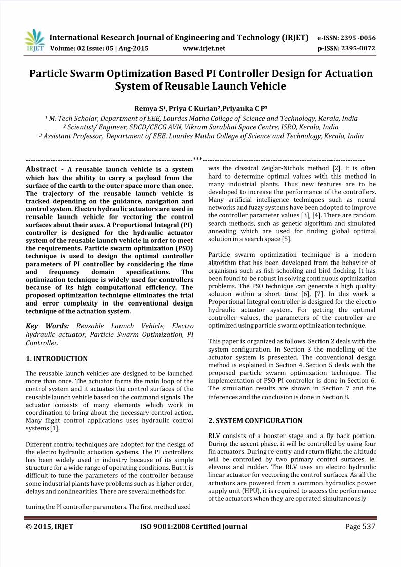
circulated. The block diagram of the electro hydraulic
actuator is shown in Fig-1. The system consists of a servo
controller, servo amplifier, hydraulic power unit, servo
valve, hydraulic actuator, control surface dynamics and a
position sensor.
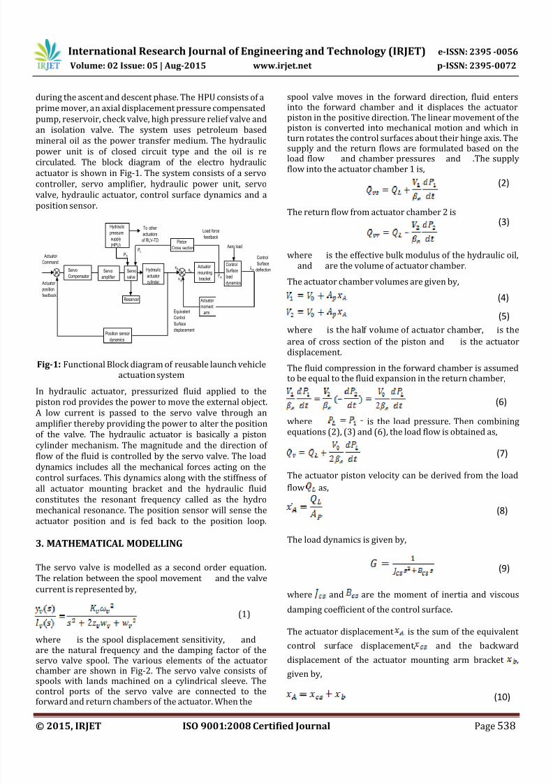
Fig-1: Functional Block diagram of reusable launch vehicleactuation system
In hydraulic actuator, pressurized fluid applied to the
piston rod provides the power to move the external object.
A low current is passed to the servo valve through anamplifier thereby providing the power to alter the position
of the valve. The hydraulic actuator is basically a piston
cylinder mechanism. The magnitude and the direction of
flow of the fluid is controlled by the servo valve. The load
dynamics includes all the mechanical forces acting on the
control surfaces. This dynamics along with the stiffness of
all actuator mounting bracket and the hydraulic fluid
constitutes the resonant frequency called as the hydro
mechanical resonance. The position sensor will sense the
actuator position and is fed back to the position loop.
3. MATHEMATICAL MODELLING
The servo valve is modelled as a second order equation.
The relation between the spool movement and the valve
current is represented by,
where is the spool displacement sensitivity, andare the natural frequency and the damping factor of theservo valve spool. The various elements of the actuatorchamber are shown in Fig-2. The servo valve consists ofspools with lands machined on a cylindrical sleeve. Thecontrol ports of the servo valve are connected to theforward and return chambers of the actuator. When the
spool valve moves in the forward direction, fluid entersinto the forward chamber and it displaces the actuatorpiston in the positive direction. The linear movement of thepiston is converted into mechanical motion and which in
turn rotates the control surfaces about their hinge axis. Thesupply and the return flows are formulated based on theload flow and chamber pressures and .The supplyflow into the actuator chamber 1 is,
The return flow from actuator chamber 2 is
where is the effective bulk modulus of the hydraulic oil,and are the volume of actuator chamber.
The actuator chamber volumes are given by,
where is the half volume of actuator chamber, is the
area of cross section of the piston and is the actuatordisplacement.
The fluid compression in the forward chamber is assumedto be equal to the fluid expansion in the return chamber,
where is the load pressure. Then combiningequations (2), (3) and (6), the load flow is obtained as,
The actuator piston velocity can be derived from the load
flow as,
The load dynamics is given by,
where and are the moment of inertia and viscous
damping coefficient of the control surface.
The actuator displacement is the sum of the equivalent
control surface displacement, and the backward
displacement of the actuator mounting arm bracket ,
given by,
Servo
Compensator Servo
amplifier
Hydraulic
actuator cylinder.
Actuator
mounting bracket
Position sensor
dynamics
Hydraulic
pressure
supply
(HPU)
+ -
Aero load
Servo
valve
Control
Surface
load
dynamics
+ -
xs
xcs
x A
Actuator
Command
Actuator
position
feedback
Piston
Cross sectionPLPS
To other
actuators
of RLV-TD
F A
Load force
feedback
Equivalent
Control
Surface
displacement
Reservoir Actuator
moment
arm
Control
Surface
deflectioncs
(3)
(4)
(5)
(6)
(7)
(8)
(1)
(9)
(10)
(2)
8/20/2019 IRJET-Particle Swarm Optimization Based PI Controller Design for Actuation System of Reusable Launch Vehicle
http://slidepdf.com/reader/full/irjet-particle-swarm-optimization-based-pi-controller-design-for-actuation 3/9
International Research Journal of Engineering and Technology (IRJET) e-ISSN: 2395 -0056
Volume: 02 Issue: 05 | Aug-2015 www.irjet.net p-ISSN: 2395-0072
© 2015, IRJET ISO 9001:2008 Certified Journal Page 539
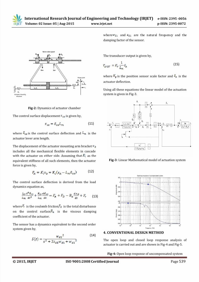
Fig-2: Dynamics of actuator chamber
The control surface displacement is given by,
where is the control surface deflection and is the
actuator lever arm length.
The displacement of the actuator mounting arm bracket
includes all the mechanical flexible elements in cascade
with the actuator on either side. Assuming that as the
equivalent stiffness of all such elements, then the actuator
force is given by,
The control surface deflection is derived from the load
dynamics equation as,
where is the coulomb friction, is the total disturbance
on the control surface, is the viscous damping
coefficient of the actuator.
The sensor has a dynamics equivalent to the second order
system given by,
where and are the natural frequency and the
damping factor of the sensor.
The transducer output is given by,
where is the position sensor scale factor and is the
actuator deflection.
Using all these equations the linear model of the actuation
system is given in Fig-3.
Fig-3: Linear Mathematical model of actuation system
4. CONVENTIONAL DESIGN METHOD
The open loop and closed loop response analysis of
actuator is carried out and are shown in Fig-4 and Fig-5.
Fig-4: Open loop response of uncompensated system
`
V1,P1 V2,P2
PR PSPR
Kl1
lmJcs,Bcs
Kl2
Qvs Qvr
Q1Q2 Q3Q4
Servo valve spool
Actuator mounting
structure
Hinge point
xcs
cs
(11)
(12)
(13)
(14)
(15)
8/20/2019 IRJET-Particle Swarm Optimization Based PI Controller Design for Actuation System of Reusable Launch Vehicle
http://slidepdf.com/reader/full/irjet-particle-swarm-optimization-based-pi-controller-design-for-actuation 4/9
International Research Journal of Engineering and Technology (IRJET) e-ISSN: 2395 -0056
Volume: 02 Issue: 05 | Aug-2015 www.irjet.net p-ISSN: 2395-0072
© 2015, IRJET ISO 9001:2008 Certified Journal Page 540
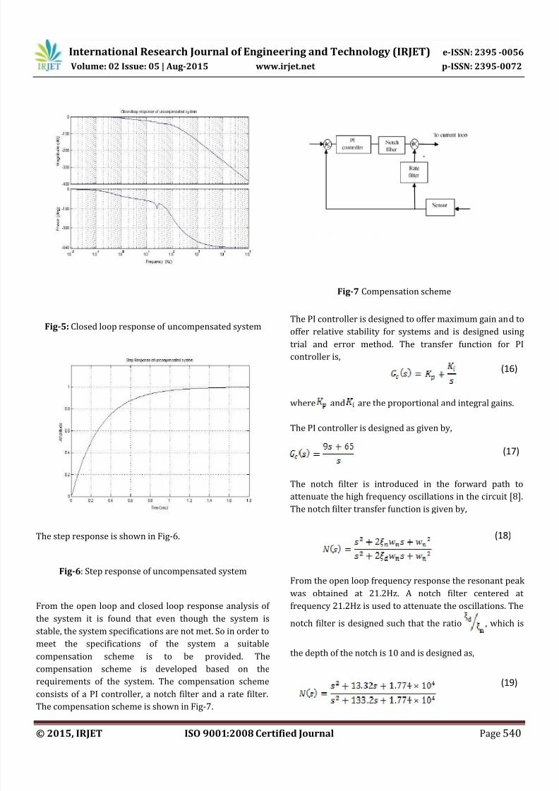
Fig-5: Closed loop response of uncompensated system
The step response is shown in Fig-6.
Fig-6: Step response of uncompensated system
From the open loop and closed loop response analysis of
the system it is found that even though the system is
stable, the system specifications are not met. So in order to
meet the specifications of the system a suitable
compensation scheme is to be provided. The
compensation scheme is developed based on the
requirements of the system. The compensation scheme
consists of a PI controller, a notch filter and a rate filter.The compensation scheme is shown in Fig-7.
Fig-7 Compensation scheme
The PI controller is designed to offer maximum gain and to
offer relative stability for systems and is designed using
trial and error method. The transfer function for PI
controller is,
where and are the proportional and integral gains.
The PI controller is designed as given by,
The notch filter is introduced in the forward path to
attenuate the high frequency oscillations in the circuit [8].
The notch filter transfer function is given by,
From the open loop frequency response the resonant peak
was obtained at 21.2Hz. A notch filter centered at
frequency 21.2Hz is used to attenuate the oscillations. The
notch filter is designed such that the ratio , which is
the depth of the notch is 10 and is designed as,
(16)
(17)
(18)
(19)
8/20/2019 IRJET-Particle Swarm Optimization Based PI Controller Design for Actuation System of Reusable Launch Vehicle
http://slidepdf.com/reader/full/irjet-particle-swarm-optimization-based-pi-controller-design-for-actuation 5/9
International Research Journal of Engineering and Technology (IRJET) e-ISSN: 2395 -0056
Volume: 02 Issue: 05 | Aug-2015 www.irjet.net p-ISSN: 2395-0072
© 2015, IRJET ISO 9001:2008 Certified Journal Page 541
The rate filter is used in the feedback path and the ratefilter transfer function is given by,
where is the rate gain and is the frequency of the rate
loop.
The rate filter is designed with 100Hz frequency as,
The simulation results with the compensation scheme are
shown in below figures. The frequency response plots are
shown in Fig-8 and Fig-9.
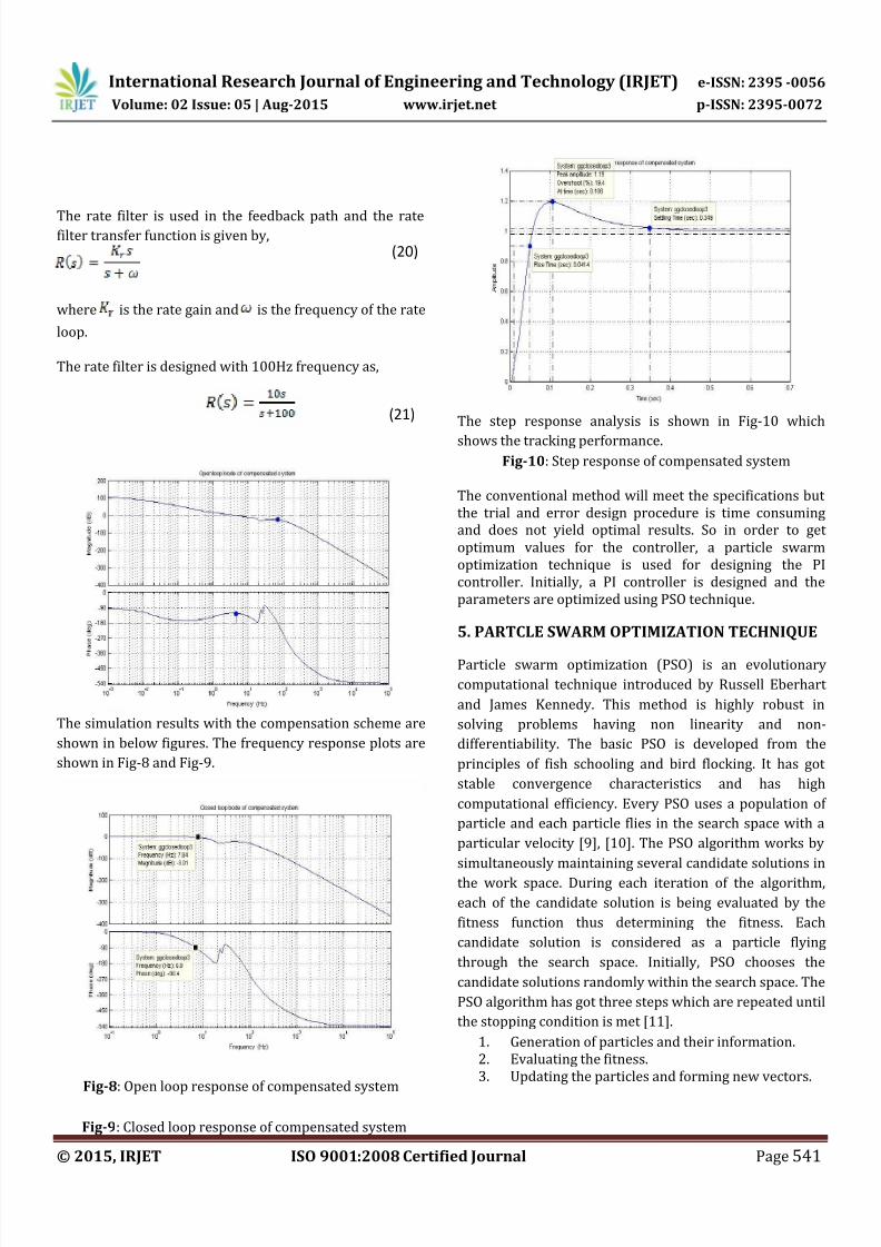
Fig-8: Open loop response of compensated system
Fig-9: Closed loop response of compensated system
The step response analysis is shown in Fig-10 which
shows the tracking performance.
Fig-10: Step response of compensated system
The conventional method will meet the specifications but
the trial and error design procedure is time consuming
and does not yield optimal results. So in order to get
optimum values for the controller, a particle swarm
optimization technique is used for designing the PI
controller. Initially, a PI controller is designed and the
parameters are optimized using PSO technique.
5. PARTCLE SWARM OPTIMIZATION TECHNIQUE
Particle swarm optimization (PSO) is an evolutionary
computational technique introduced by Russell Eberhart
and James Kennedy. This method is highly robust in
solving problems having non linearity and non-
differentiability. The basic PSO is developed from the
principles of fish schooling and bird flocking. It has got
stable convergence characteristics and has high
computational efficiency. Every PSO uses a population of
particle and each particle flies in the search space with a
particular velocity [9], [10]. The PSO algorithm works by
simultaneously maintaining several candidate solutions in
the work space. During each iteration of the algorithm,
each of the candidate solution is being evaluated by the
fitness function thus determining the fitness. Each
candidate solution is considered as a particle flying
through the search space. Initially, PSO chooses the
candidate solutions randomly within the search space. The
PSO algorithm has got three steps which are repeated until
the stopping condition is met [11].
1.
Generation of particles and their information.
2.
Evaluating the fitness.
3.
Updating the particles and forming new vectors.
(20)
(21)
8/20/2019 IRJET-Particle Swarm Optimization Based PI Controller Design for Actuation System of Reusable Launch Vehicle
http://slidepdf.com/reader/full/irjet-particle-swarm-optimization-based-pi-controller-design-for-actuation 6/9
International Research Journal of Engineering and Technology (IRJET) e-ISSN: 2395 -0056
Volume: 02 Issue: 05 | Aug-2015 www.irjet.net p-ISSN: 2395-0072
© 2015, IRJET ISO 9001:2008 Certified Journal Page 542
The information of the particle refers to the position
and velocity. A set of particles, is first initialized having
position and velocity and an evaluation function is
formulated based on the system requirements. Then thefunction is evaluated with each of the particle as the input
vectors. The position and the velocity of the particle can be
changed at each time step. When a particle discovers that
any value obtained is better than the previously obtained
value, then it stores that value as , the personal best
value [12]. The overall best value among the personal best
values is the value represented by . The position and
velocities are initialized first. Let and are the
upper and lower bound of the position of the particle. The
position of the particle can be obtained as,
where refers to a random number between 0 and
1.
Fitness evaluation is conducted by applying the candidate
solution to the function formulated. Individual and global
best positions are updated by comparing the new fitness
value with the previously obtained value.
The velocity of each particle is updated using the formula
[12],
where is the number of iterations, is the inertia weight
which provides a balance between the personal and the
global values. The value of ranges from 0.4 to 0.9 and it
is calculated as [12],
where is the maximum number of iterations. The
constants and are the acceleration constant terms
that makes the solution near to or away from the personal
and global best values. The acceleration constants are
usually in the range of 1.5 or 2. Once the velocity of each
particle is calculated, then the position is updated by
applying the new velocity to the particles previous
position as [12],
6. IMPLEMENTATION OF PSO-PI CONTROLLER
A PI controller is designed using the PSO technique. The
gain values of the PI controller are optimized using this
method. The particles are represented by the parametersof the controller. The open loop transfer function of the
system is given by,
The PI controller is designed as follows,
Step 1: The magnitude and phase at , the gain cross
over frequency is calculated.
Step 2: The phase margin of the uncompensated system
and the angle to be contributed to achieve the desired
phase margin is to be determined. Let be the phase
margin of the uncompensated system, be the desired
phase margin, be the phase angle of the controller at
. Then the phase margin of the uncompensated
system is given by, and the phase angle is
given by
Step 3: The PI controller is designed as,
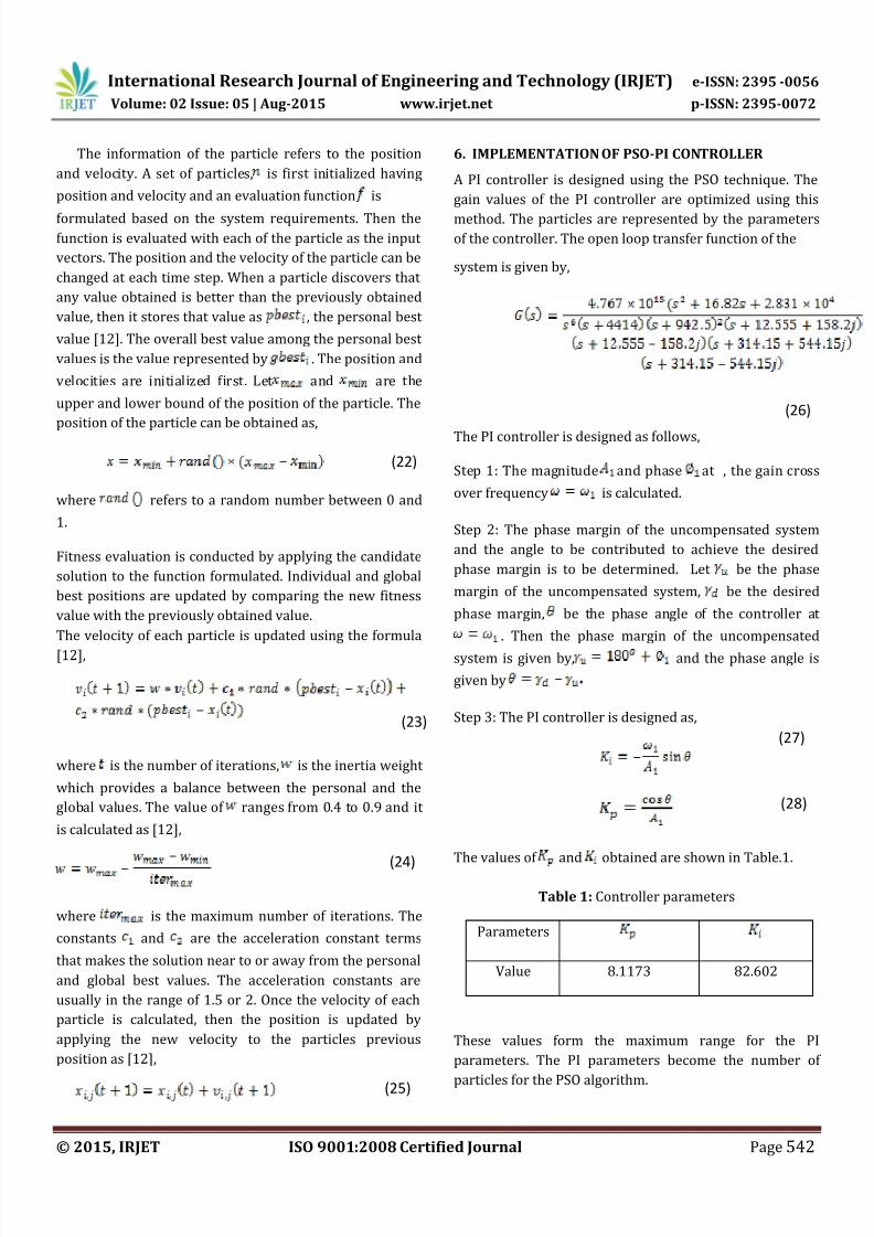
The values of and obtained are shown in Table.1.
Table 1: Controller parameters
Parameters
Value 8.1173 82.602
These values form the maximum range for the PI
parameters. The PI parameters become the number of
particles for the PSO algorithm.
(22)
(23)
(24)
(25)
(27)
(28)
(26)
8/20/2019 IRJET-Particle Swarm Optimization Based PI Controller Design for Actuation System of Reusable Launch Vehicle
http://slidepdf.com/reader/full/irjet-particle-swarm-optimization-based-pi-controller-design-for-actuation 7/9
International Research Journal of Engineering and Technology (IRJET) e-ISSN: 2395 -0056
Volume: 02 Issue: 05 | Aug-2015 www.irjet.net p-ISSN: 2395-0072
© 2015, IRJET ISO 9001:2008 Certified Journal Page 543
Considering there are individuals in a population. Since
there are two parameters to control, then the dimension of
the population is . The position represents the
parameters of the PI controller and the initial values aregiven by,
A fitness function is to be formulated for the PSO
algorithm. The function is designed based on the time
domain specifications and it includes rise time , settling
time and overshoot . The evaluation function is
formulated as the sum of the ratios of settling time, rise
time and the overshoot. The function is given by,
where , and are the settling time, rise time and
overshoot values of the required system with the
controller. For each of the iteration process the value is
changed and the fitness function is calculated. The
searching procedure for the PSO-PI controller is asfollows:
Step 1: Specify the lower and upper bounds of the
controller parameters and initialize randomly the position,
velocities and local best values. Enter the maximum
number of iterations which is taken as 50.
Step 2: For each of the individuals, evaluate the fitness
function consisting of , and .
Step3: Compare each individual’s new fitness value with
the best value initialized . The best value among the
is the value.
Step 4: Modify the velocity of the particle and update the
position of the particle using the new velocity.
Step 5: When the number of iteration reaches the
maximum, then it is stopped. The latest value is
taken as the optimal controller parameters of the PI
controller.
The simulation parameters are taken as given in Table 2.
Table 2: Parameters of PSO algorithm
Parameter Values
Population size, n 50
Inertia weight wmax, wmin 0.9, 0.4
Acceleration constants c1,c2 2
After optimization the values of the PI controller are
obtained are shown in Table 3.
Table.3: Optimal controller parameters
Parameter
Optimized value 7.5469 26.9698
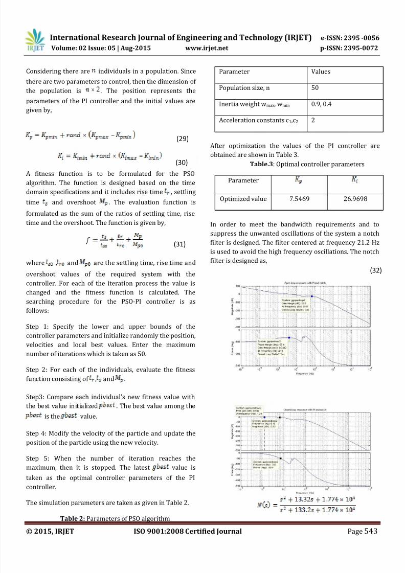
In order to meet the bandwidth requirements and to
suppress the unwanted oscillations of the system a notch
filter is designed. The filter centered at frequency 21.2 Hz
is used to avoid the high frequency oscillations. The notch
filter is designed as,
(29)
(30)
(32)
(31)
8/20/2019 IRJET-Particle Swarm Optimization Based PI Controller Design for Actuation System of Reusable Launch Vehicle
http://slidepdf.com/reader/full/irjet-particle-swarm-optimization-based-pi-controller-design-for-actuation 8/9
International Research Journal of Engineering and Technology (IRJET) e-ISSN: 2395 -0056
Volume: 02 Issue: 05 | Aug-2015 www.irjet.net p-ISSN: 2395-0072
© 2015, IRJET ISO 9001:2008 Certified Journal Page 544
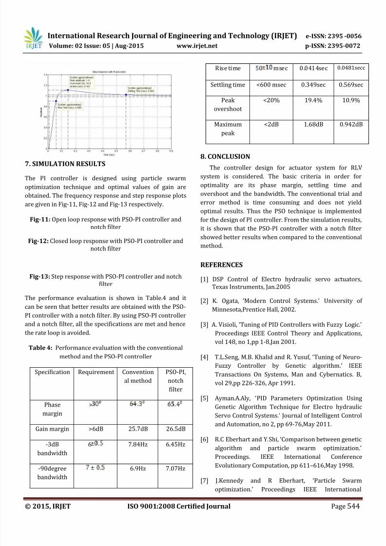
7. SIMULATION RESULTS
The PI controller is designed using particle swarm
optimization technique and optimal values of gain are
obtained. The frequency response and step response plots
are given in Fig-11, Fig-12 and Fig-13 respectively.
Fig-11: Open loop response with PSO-PI controller and
notch filter
Fig-12: Closed loop response with PSO-PI controller and
notch filter
Fig-13: Step response with PSO-PI controller and notch
filter
The performance evaluation is shown in Table.4 and it
can be seen that better results are obtained with the PSO-
PI controller with a notch filter. By using PSO-PI controller
and a notch filter, all the specifications are met and hence
the rate loop is avoided.
Table 4: Performance evaluation with the conventional
method and the PSO-PI controller
Specification Requirement Convention
al method
PSO-PI,
notchfilter
Phase
margin
>
Gain margin >6dB 25.7dB 26.5dB
-3dB
bandwidth
6 7.84Hz 6.45Hz
-90degree
bandwidth
6.9Hz 7.07Hz
Rise time 50 msec 0.0414sec 0.0481secc
Settling time <600 msec 0.349sec 0.569sec
Peak
overshoot
<20% 19.4% 10.9%
Maximum
peak
<2dB 1.68dB 0.942dB
8. CONCLUSION
The controller design for actuator system for RLV
system is considered. The basic criteria in order for
optimality are its phase margin, settling time and
overshoot and the bandwidth. The conventional trial and
error method is time consuming and does not yield
optimal results. Thus the PSO technique is implemented
for the design of PI controller. From the simulation results,
it is shown that the PSO-PI controller with a notch filter
showed better results when compared to the conventional
method.
REFERENCES
[1] DSP Control of Electro hydraulic servo actuators,
Texas Instruments, Jan.2005
[2] K. Ogata, ‘Modern Control Systems.’ University of
Minnesota,Prentice Hall, 2002.
[3] A. Visioli, ‘Tuning of PID Controllers with Fuzzy Logic.’
Proceedings IEEE Control Theory and Applications,
vol 148, no 1,pp 1-8,Jan 2001.
[4] T.L.Seng, M.B. Khalid and R. Yusuf, ‘Tuning of Neuro-
Fuzzy Controller by Genetic algorithm.’ IEEE
Transactions On Systems, Man and Cybernatics. B,
vol 29,pp 226-326, Apr 1991.
[5] Ayman.A.Aly, ‘PID Parameters Optimization Using
Genetic Algorithm Technique for Electro hydraulic
Servo Control Systems.’ Journal of Intelligent Control
and Automation, no 2, pp 69-76,May 2011.
[6] R.C Eberhart and Y.Shi, ‘Comparison between genetic
algorithm and particle swarm optimization.’
Proceedings. IEEE International Conference
Evolutionary Computation, pp 611–616,May 1998.
[7] J.Kennedy and R Eberhart, ‘Particle Swarm
optimization.’ Proceedings IEEE International
8/20/2019 IRJET-Particle Swarm Optimization Based PI Controller Design for Actuation System of Reusable Launch Vehicle
http://slidepdf.com/reader/full/irjet-particle-swarm-optimization-based-pi-controller-design-for-actuation 9/9
International Research Journal of Engineering and Technology (IRJET) e-ISSN: 2395 -0056
Volume: 02 Issue: 05 | Aug-2015 www.irjet.net p-ISSN: 2395-0072
© 2015, IRJET ISO 9001:2008 Certified Journal Page 545
Conference on Neural Networks, Perth, Australia, vol
IV,pp 1942-1948,1995
[8] P. Schmidt and T.Rehm, ‘ Notch Filter Tuning for
Resonant Frequency Reduction in Dual Inertia
Systems.’Proceedings of IEEE Industry Applications
Conference, vol.3, pp 1730-1734, Oct 1999.
[9] Zwe-Lee Gaing, ‘A Particle Swarm optimization
Approach for Optimum design of PID Controller in
AVR System.’ IEEE Transactions on Energy
Conversion, vol 19,no 2, June 2004.
[10] Mahmud Iwan Solihin, Lee Fook Tack and Moey
Leap Kean, ‘Tuning of PID Controller Using Particle
Swarm Optimization.’ Proceedings of International
Conference on Advanced Science, Engineering andInformation Technology , pp 458-461, Jan 2011.
[11] Trias Andromeda, Azli Yahya, Nor Hisham Haji
Khamis, Ameruddin Baharom and Muhammad
Arifabdul Rahim, ‘PID Controller Tuning by Particle
Swarm Optimization on Electrical Discharge
Machining Servo Control System.’ International
Conference on Intelligent and Advanced Systems, pp
51-55, 2011.
[12] James Blondin, ‘Particle swarm optimization: A
Tutorial.’ September 2009.