Embed Size (px)
Citation preview
iRIS Under Cover Datalogger
Reference Manual
For Firmware Version: 1.5.5
2 HyQuest Solutions (NZ) Ltd - PO Box 9466, Hamilton, New Zealand Tel: +64 7 857-0810 Email: [email protected]
Disclaimer Under no circumstances will HyQuest Solutions (NZ) Ltd be liable or responsible for any consequential damage or loss that may arise from the use of this product. All examples and diagrams shown in this manual and any supplied software examples are intended as a guide to understanding this product, not to guarantee operation. HyQuest Solutions (NZ) Ltd accepts no responsibility for use of this product based on this information or these examples. Owing to the wide variety of possible applications of this product, you must satisfy yourself as to its suitability to your specific application. © 2003-2019 HyQuest Solutions (NZ) Ltd All rights reserved. This publication, or any part of it, and any software accompanying it may not be copied, photocopied, reproduced, translated or communicated to any third party, or reduced to electronic medium without prior written permission from HyQuest Solutions (NZ) Ltd.
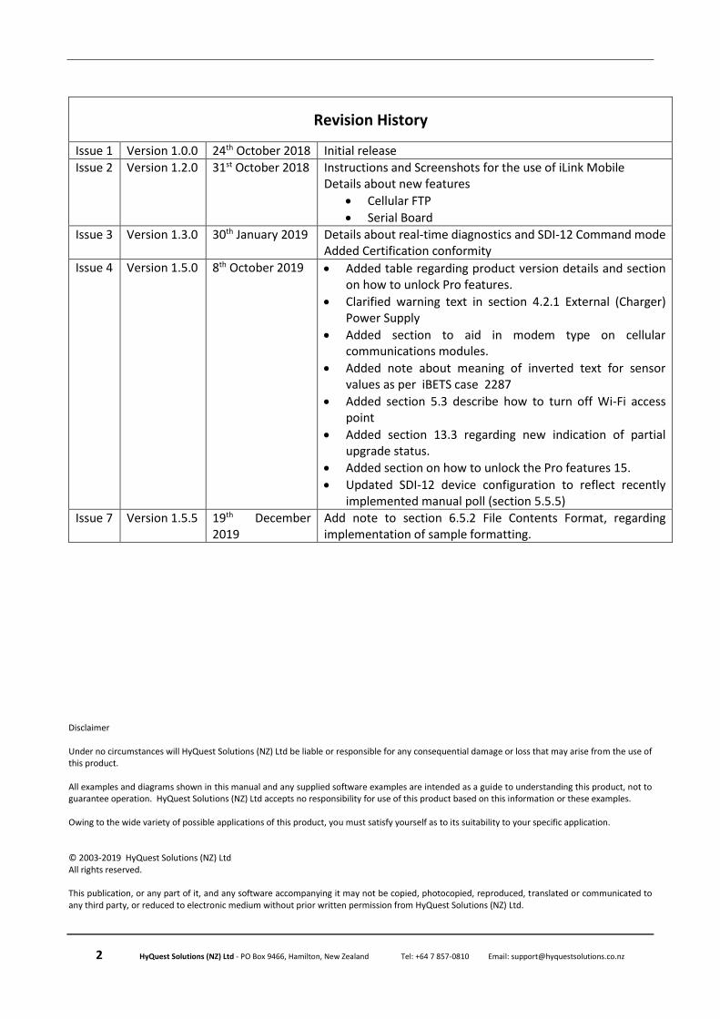
Revision History
Issue 1 Version 1.0.0 24th October 2018 Initial release
Issue 2 Version 1.2.0 31st October 2018 Instructions and Screenshots for the use of iLink Mobile Details about new features
• Cellular FTP
• Serial Board
Issue 3 Version 1.3.0 30th January 2019 Details about real-time diagnostics and SDI-12 Command mode Added Certification conformity
Issue 4 Version 1.5.0 8th October 2019 • Added table regarding product version details and section on how to unlock Pro features.
• Clarified warning text in section 4.2.1 External (Charger) Power Supply
• Added section to aid in modem type on cellular communications modules.
• Added note about meaning of inverted text for sensor values as per iBETS case 2287
• Added section 5.3 describe how to turn off Wi-Fi access point
• Added section 13.3 regarding new indication of partial upgrade status.
• Added section on how to unlock the Pro features 15.
• Updated SDI-12 device configuration to reflect recently implemented manual poll (section 5.5.5)
Issue 7 Version 1.5.5 19th December 2019
Add note to section 6.5.2 File Contents Format, regarding implementation of sample formatting.
i HyQuest Solutions (NZ) Ltd - PO Box 9466, Hamilton, New Zealand Tel: +64 7 857-0810 Email: [email protected]
Contents 1 Declaration of Conformity ....................................................................................................... i
2 Introduction ........................................................................................................................... 2
2.1 About this Manual ..................................................................................................................... 2
2.2 Support ...................................................................................................................................... 2
3 Overview ............................................................................................................................... 3
3.1 Introduction .............................................................................................................................. 3
3.2 Typical Applications .................................................................................................................. 3
3.3 Key Features .............................................................................................................................. 3 3.3.1 Product Versions ................................................................................................................ 3 3.3.2 Telemetry and SDI-12 Diagnostics ..................................................................................... 4 3.3.3 Power Management .......................................................................................................... 4 3.3.4 Data Logging ...................................................................................................................... 5 3.3.5 Logged Data Array Identification ....................................................................................... 5 3.3.6 Alarm Processing ............................................................................................................... 6 3.3.7 Real Time Clock & Calendar ............................................................................................... 6
4 Installation ............................................................................................................................. 7
4.1 Opening / Closing the Housing .................................................................................................. 7
4.2 I/O Connector............................................................................................................................ 7 4.2.1 External (Charger) Power Supply ....................................................................................... 8 4.2.2 Analogue I/O .................................................................................................................... 10
4.2.2.1 Analogue Inputs ........................................................................................................ 10 4.2.2.2 Analogue Output ...................................................................................................... 11
4.2.3 Digital I/O ......................................................................................................................... 11 4.2.3.1 Digital Channels as Inputs ......................................................................................... 11 4.2.3.2 Digital Output ........................................................................................................... 12
4.2.4 Serial Sensor Interface (SSI) ............................................................................................. 13 4.2.4.1 Selecting Serial Mode ............................................................................................... 13
4.3 Telemetry Module................................................................................................................... 15 4.3.1 Cellular ............................................................................................................................. 15
4.3.1.1 Removing / fitting the SIM card ............................................................................... 15 4.3.1.2 Cellular Modem Type Identification ......................................................................... 15 4.3.1.3 Antenna Connectors ................................................................................................. 15
5 Configuration ....................................................................................................................... 17
5.1 Connecting to the iRIS 270 with iLink Desktop software via Wi-Fi (Windows 10) .................. 17
5.2 Connecting to the iRIS 270 with iLink Mobile software via Wi-Fi (Android) ........................... 18
5.3 Turn off Wi-Fi Access Point ..................................................................................................... 20
5.4 Changing the Wi-Fi password with iLink Desktop software via Wi-Fi (Windows 10) ............. 20
5.5 Configuration Menus .............................................................................................................. 22 5.5.1 System.............................................................................................................................. 22 5.5.2 Power ............................................................................................................................... 23 5.5.3 I/O Configuration ............................................................................................................. 24
5.5.3.1 Analogue I/O ............................................................................................................. 24 5.5.3.2 Digital I/O .................................................................................................................. 25
5.5.4 Comms ............................................................................................................................. 27 5.5.4.1 Wi-Fi .......................................................................................................................... 27

ii HyQuest Solutions (NZ) Ltd - PO Box 9466, Hamilton, New Zealand Tel: +64 7 857-0810 Email: [email protected]
5.5.4.2 Addressing ................................................................................................................ 27 5.5.4.3 Serial Sensor Interface (SSI) ...................................................................................... 28 5.5.4.4 Modem ..................................................................................................................... 29 5.5.4.5 Schedule ................................................................................................................... 30 5.5.4.6 Cellular Modem - FTP 1 & FTP 2 ............................................................................... 32 5.5.4.7 TCP ............................................................................................................................ 33
5.5.5 SDI-12 Devices ................................................................................................................. 34 5.5.6 Digital Devices .................................................................................................................. 35 5.5.7 Sensor Configuration ....................................................................................................... 37
5.5.7.1 General ..................................................................................................................... 37 5.5.7.2 Logging ...................................................................................................................... 39
5.5.8 Alarm Configuration ........................................................................................................ 42 5.5.9 SMS Numbers .................................................................................................................. 43 5.5.10 User Messages ................................................................................................................. 44
6 Operation ............................................................................................................................ 45
6.1 LED Indicators ......................................................................................................................... 45 6.1.1 Status LED ........................................................................................................................ 45 6.1.2 Front panel Diagnostic LEDs ............................................................................................ 45
6.2 Keypad Button......................................................................................................................... 45
6.3 Solar Regulator ........................................................................................................................ 46 6.3.1 Charging Batteries cycles ................................................................................................. 46
6.3.1.1 Sealed Lead Acid Batteries ....................................................................................... 46 6.3.1.2 Lithium Ion / Lithium Polymer Batteries .................................................................. 47
6.3.2 Operation ......................................................................................................................... 47 6.3.2.1 Charging Source ........................................................................................................ 47 6.3.2.2 Charge Algorithm Stages .......................................................................................... 48
6.3.3 Charger LED Flash States ................................................................................................. 48
6.4 SMS Communication ............................................................................................................... 49 6.4.1 SMS Text Commands ....................................................................................................... 49
6.5 File Transfer Protocol (FTP) Operation ................................................................................... 50 6.5.1 File Name Convention ..................................................................................................... 50 6.5.2 File Contents Format ....................................................................................................... 51
6.6 General Hints .......................................................................................................................... 51
7 Diagnostics ........................................................................................................................... 52
7.1 Real-time Diagnostics .............................................................................................................. 52
8 SDI-12 Command Mode (Pro Version Only) ........................................................................... 54
8.1 Accessing ................................................................................................................................. 54
8.2 Sending user command to device ........................................................................................... 55
8.3 Address Change function ........................................................................................................ 55
8.4 Address Scan ........................................................................................................................... 55
9 Using iLink 2012’s Sensor Configuration Tool ......................................................................... 56
9.1 iRIS Sensor Configuration Example ......................................................................................... 56
10 Analogue Input Scaling ...................................................................................................... 61
11 Modbus Protocol .............................................................................................................. 62
11.1 Protocol Overview ............................................................................................................... 62
11.2 Example of iRIS acting as a Master ...................................................................................... 66
iii HyQuest Solutions (NZ) Ltd - PO Box 9466, Hamilton, New Zealand Tel: +64 7 857-0810 Email: [email protected]
11.3 Example of iRIS acting as a Slave Sensor ............................................................................. 69
11.4 Example of iRIS acting as a protocol gateway (Modbus Slave) ........................................... 72
12 Appendix A – Specific Information ..................................................................................... 75
12.1 General Characteristics ....................................................................................................... 75
12.2 Technical Specifications ....................................................................................................... 76
12.3 Mounting ............................................................................................................................. 77
13 Appendix B – Upgrading Firmware ..................................................................................... 78
13.1 Overview .............................................................................................................................. 78
13.2 File Naming Conventions ..................................................................................................... 78 13.2.1 iRIS Executive Firmware ................................................................................................... 78
13.3 Active verse Pending Firmware ........................................................................................... 78
13.4 iRIS Automated Upgrade Procedure (Firmware)................................................................. 79
13.5 iRIS Manual Upgrade Procedure (Firmware) ...................................................................... 80
14 APPENDIX C – SDI-12 ......................................................................................................... 81
14.1 What is SDI-12? ................................................................................................................... 81
14.2 Advantages of SDI-12 .......................................................................................................... 81
14.3 SDI-12 Electrical Interface ................................................................................................... 82 14.3.1 Serial Data Line ................................................................................................................ 82 14.3.2 Ground Line ..................................................................................................................... 82 14.3.3 Volt-Line ........................................................................................................................... 82
15 Unlock Pro Features .......................................................................................................... 83
16 User Notes ........................................................................................................................ 84
Tables / Figures Table 1 feature list describing those available in each version ......................................................................... 3 Table 2 – SSI terminal definition ...................................................................................................................... 13 Table 3 - Digital Output Modes ....................................................................................................................... 25 Table 4 - Digital Output Polarity ...................................................................................................................... 26 Table 5 – Standard Sensor Sources ................................................................................................................. 39 Table 6 – Shows the front panel Comms status LED sequence for cellular module ....................................... 45 Table 7 – Shows the solar charge status LED sequence .................................................................................. 49 Table 8 – Supported reading function codes when the iRIS is a Master ........................................................ 64 Table 9 – Data types supported by the iRIS .................................................................................................... 64 Table 10 – Location of example slave register Map in Figure 20 .................................................................... 64 Table 11 – Modbus holding register map for iRIS sensors .............................................................................. 65 Table 12 – Data flow visualisation of the Modbus gateway example ............................................................. 74 Table 13 – Logic and voltage levels for serial data on SDI-12 bus ................................................................... 82 Figure 1 – Right hand side I/O Connector ......................................................................................................... 7 Figure 2 – Left hand side I/O Connector ............................................................................................................ 8 Figure 3 – Shows examples of the correct and incorrect methods of connecting the logger to power source
and an external battery .............................................................................................................................. 9 Figure 4 – Simplified Analogue Input Circuit ................................................................................................... 10 Figure 5 – Analogue Input / Output Links........................................................................................................ 10 Figure 6 - Digital Input Debounce Links ........................................................................................................... 11
iv HyQuest Solutions (NZ) Ltd - PO Box 9466, Hamilton, New Zealand Tel: +64 7 857-0810 Email: [email protected]
Figure 7 – Digital Input Circuit ......................................................................................................................... 12 Figure 8 – Pull-Down Mode Circuit .................................................................................................................. 13 Figure 9 – Switched 12V Mode Circuit ............................................................................................................ 13 Figure 10 - location of serial mode selection jumpers .................................................................................... 14 Figure 11 - detail depiction of RS-232 / RS-485 jumper positions .................................................................. 14 Figure 12 – SIM Carrier .................................................................................................................................... 15 Figure 13 – Location of cellular modem model number and table of modem technologies .......................... 15 Figure 14 – antenna connector view ............................................................................................................... 16 Figure 15 – (Ideal charging of an SLA battery)................................................................................................. 46 Figure 16 – Ideal charging of a LiIon battery pack ........................................................................................... 47 Figure 17- Location of solar regulator status LED (Red) .................................................................................. 48 Figure 18 – Block diagram of an example of physical connection of Modbus devices to the iRIS. ................. 62 Figure 19 – Block diagram of the application topologies that can be implemented by the iRIS. Note the RS-
485 bus can be replaced with an RS-232 connection, with a single slave. .............................................. 63 Figure 20 – Example of slave register map in iLink.......................................................................................... 64 Figure 21 - iRIS Under Cover External View ..................................................................................................... 75 Figure 22 - Mounting Diagram ........................................................................................................................ 77
iRIS Under Cover Reference Manual
i HyQuest Solutions (NZ) Ltd - PO Box 9466, Hamilton, New Zealand Tel: +64 7 857-0810 Email: [email protected]
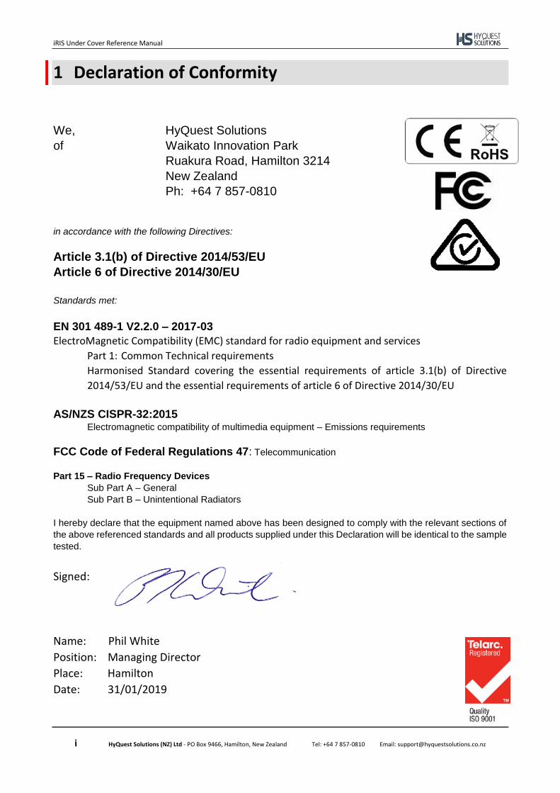
1 Declaration of Conformity
We, HyQuest Solutions
of Waikato Innovation Park
Ruakura Road, Hamilton 3214
New Zealand
Ph: +64 7 857-0810
in accordance with the following Directives:
Article 3.1(b) of Directive 2014/53/EU
Article 6 of Directive 2014/30/EU
Standards met:
EN 301 489-1 V2.2.0 – 2017-03
ElectroMagnetic Compatibility (EMC) standard for radio equipment and services
Part 1: Common Technical requirements
Harmonised Standard covering the essential requirements of article 3.1(b) of Directive
2014/53/EU and the essential requirements of article 6 of Directive 2014/30/EU
AS/NZS CISPR-32:2015 Electromagnetic compatibility of multimedia equipment – Emissions requirements
FCC Code of Federal Regulations 47: Telecommunication
Part 15 – Radio Frequency Devices
Sub Part A – General
Sub Part B – Unintentional Radiators
I hereby declare that the equipment named above has been designed to comply with the relevant sections of
the above referenced standards and all products supplied under this Declaration will be identical to the sample
tested.
Signed:
Name: Phil White
Position: Managing Director
Place: Hamilton
Date: 31/01/2019
iRIS Under Cover Reference Manual
2 HyQuest Solutions (NZ) Ltd - PO Box 9466, Hamilton, New Zealand Tel: +64 7 857-0810 Email: [email protected]
2 Introduction
2.1 About this Manual
This manual is intended as a detailed guide for iRIS Under Cover installation, configuration and operation. This manual is also available online in at www.hyquestsolutions.co.nz Throughout this document, small icons are used to identify additional information. These are as follows:
NOTE Indicates extra detail to expand the current discussion. WARNING Describes something that may cause problems if not heeded.
NOTE: The term “iRIS” is used throughout this manual in all references to the iRIS Under Cover.
2.2 Support
Technical support for the iRIS Under Cover is available by contacting: HyQuest Solutions (NZ) Ltd P.O Box 9466 Hamilton NEW ZEALAND Tel: +64 7 857-0810 Email: [email protected] For latest information and software updates, visit the HyQuest Solutions (NZ) Ltd web site at www.hyquestsolutions.co.nz
iRIS Under Cover Reference Manual
3 HyQuest Solutions (NZ) Ltd - PO Box 9466, Hamilton, New Zealand Tel: +64 7 857-0810 Email: [email protected]
3 Overview
3.1 Introduction
The iRIS (iQuest Remote Information Source) datalogger range has been designed as cost effective, low power, self-contained information source for use in a wide range of data gathering and logging applications.
3.2 Typical Applications
The iRIS can be used for a wide range of diverse applications, including but not limited to:
▪ Rainfall measurement
▪ River level monitoring
▪ Water / power / gas metering
▪ Remote control
▪ Wind measurement
▪ Mobile temperature monitoring
▪ Irrigation monitoring / control
▪ IP → RS232 communications gateway
3.3 Key Features
3.3.1 Product Versions
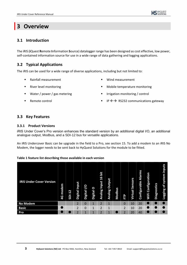
iRIS Under Cover’s Pro version enhances the standard version by an additional digital I/O, an additional analogue output, Modbus, and a SDI-12 bus for versatile applications.
An iRIS Undercover Basic can be upgrade in the field to a Pro, see section 15. To add a modem to an iRIS No Modem, the logger needs to be sent back to HyQuest Solutions for the module to be fitted.
Table 1 feature list describing those available in each version
iRIS Under Cover Version
4G
mo
dem
SDI-
12
Dig
ital
Inp
ut
Dig
ital
I/O
Dig
ital
O
An
alo
g In
pu
t 16
bit
An
alo
g O
utp
ut
Mo
db
us
FTP
Vir
tual
Sen
sors
Co
nfi
gura
ble
Ala
rms
WiF
i Co
nfi
gura
tio
n
Dia
gno
stic
s
Logg
ing
of
syst
em
inp
uts
No Modem 2 0 1 2 1 0 10 20
Basic 2 0 1 2 1 2 10 20
Pro 2 1 1 2 1 2 20 40

iRIS Under Cover Reference Manual
4 HyQuest Solutions (NZ) Ltd - PO Box 9466, Hamilton, New Zealand Tel: +64 7 857-0810 Email: [email protected]
3.3.2 Telemetry and SDI-12 Diagnostics
Monitoring operation of the communications modules and SDI-12 bus is possible from the iLink software. The Architecture allow for remote monitoring, monitoring over open channels (Radio) even monitoring of the operation of the channel being used. The information obtained is time stamped real time log with three levels (information, warning/error, trace), which this can be filtered and captured for later analysis.
3.3.3 Power Management
TBD
iRIS Under Cover Reference Manual
5 HyQuest Solutions (NZ) Ltd - PO Box 9466, Hamilton, New Zealand Tel: +64 7 857-0810 Email: [email protected]
3.3.4 Data Logging
The iRIS supports the logging of data from up to twenty virtual sensors. Each of the virtual sensors can obtain information from one of the following data sources:
• Analogue input on AIN1 – AIN2
• Pulse counter attached to DI1, DI2 or DIO
• Simulated pulse counter enabled by DI1, DI2 or DIO
• Frequency counter attached to DI1, DI2 or DIO
• Up/down counter attached to DI1, DI2 or DIO simultaneously
• SDI-12 instrument channel 1
• Change of status on charger input (dc supply)
• Battery voltage
• Supply (charger) voltage
• Logger temperature
• Received Signal Strength Indication (RSSI)
• Change Of State on digital I/O channels DI1, DI2 or DIO
• Serial instrument (using the Modbus protocol)1 Each sensor can be set up to scale the raw data source into engineering units through the application of a multiplier and offset (slope and constant). The scaled value can be logged to non-volatile memory at rates between once per minute to once per hour or immediately in true event mode for pulse inputs. It is also possible to configure a sensor to also log associated values such as minimum, maximum, standard deviation (for all source types) or a calculated flow rate or volume (pulse type sources only). See the next section for further details on configuring these extended logging features as part of the Sensor Cfg menus.
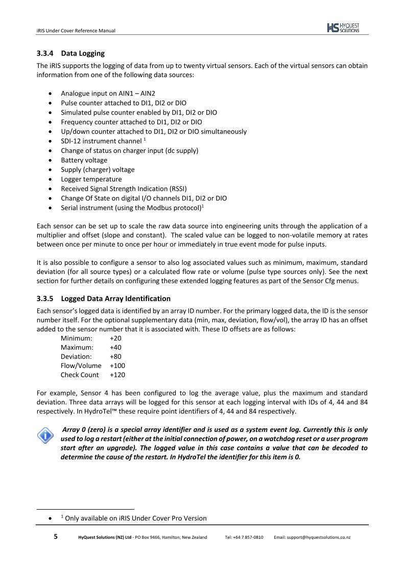
3.3.5 Logged Data Array Identification
Each sensor’s logged data is identified by an array ID number. For the primary logged data, the ID is the sensor number itself. For the optional supplementary data (min, max, deviation, flow/vol), the array ID has an offset added to the sensor number that it is associated with. These ID offsets are as follows:
Minimum: +20 Maximum: +40 Deviation: +80 Flow/Volume +100 Check Count +120
For example, Sensor 4 has been configured to log the average value, plus the maximum and standard deviation. Three data arrays will be logged for this sensor at each logging interval with IDs of 4, 44 and 84 respectively. In HydroTel™ these require point identifiers of 4, 44 and 84 respectively.
Array 0 (zero) is a special array identifier and is used as a system event log. Currently this is only used to log a restart (either at the initial connection of power, on a watchdog reset or a user program start after an upgrade). The logged value in this case contains a value that can be decoded to determine the cause of the restart. In HydroTel the identifier for this item is 0.
• 1 Only available on iRIS Under Cover Pro Version
iRIS Under Cover Reference Manual
6 HyQuest Solutions (NZ) Ltd - PO Box 9466, Hamilton, New Zealand Tel: +64 7 857-0810 Email: [email protected]
3.3.6 Alarm Processing
There is a “pool” of up to 40 free-format alarms. These can be assigned to any virtual sensor. So it is possible to have two alarms on every sensor or else more on some sensors and less or none on others. Each alarm has separate trigger and reset levels, an activation delay or accumulation period depending upon the data type, comms interval, enable call-in and an option to send a customised SMS text to a specified number when the alarm is triggered. Each sensor has an associated flag that is set if any alarm on the sensor is active. This can be used to vary the logging rate for the sensor. For example, taking more frequent logs when water level is high compared to a less frequent “routine” log in normal conditions. The iRIS also maintains a global “alarms active” flag that is set if any alarm on any sensor in the device is active. This is used to trigger a call-in or data transfer to the designated host. As well as the call-in, this flag can also control the digital outputs.
3.3.7 Real Time Clock & Calendar
The iRIS has a non-volatile real time clock that can be read and/or synchronised using HydroTel™ or iLink 2012.
iRIS Under Cover Reference Manual
7 HyQuest Solutions (NZ) Ltd - PO Box 9466, Hamilton, New Zealand Tel: +64 7 857-0810 Email: [email protected]
4 Installation
4.1 Opening / Closing the Housing
The front of the iRIS enclosure is secured by four quarter turn locking pins with Phillips® heads. To Open: Undo all four locking pins by pressing down with screwdriver and rotate a quarter turn in the anti-clockwise direction. The pin has a spring, which eject the pin to the open state. The pins are retained in the lid. The front cover should then be lifted away from the base, note there not any hinges so care should be taken not to place any stress on the ribbon cable between the base and lid. To Close: Place the lid on the base, ensuring the ribbon cable does not pinch. In turn, apply pressure to each pin so that the spring is completely pressed, then turn clockwise a quarter turn until locked.
4.2 I/O Connector
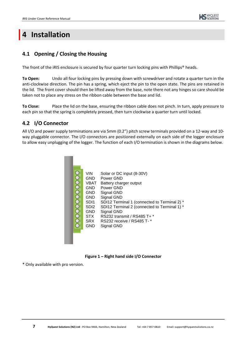
All I/O and power supply terminations are via 5mm (0.2”) pitch screw terminals provided on a 12-way and 10- way pluggable connector. The I/O connectors are positioned externally on each side of the logger enclosure to allow easy unplugging of the logger. The function of each I/O termination is shown in the diagrams below.
Figure 1 – Right hand side I/O Connector
* Only available with pro version.
VIN Solar or DC input (8-30V) GND Power GND VBAT Battery charger output GND Power GND GND Signal GND GND Signal GND SDI1 SDI12 Terminal 1 (connected to Terminal 2) * SDI2 SDI12 Terminal 2 (connected to Terminal 1) * GND Signal GND STX RS232 transmit / RS485 T+ * SRX RS232 receive / RS485 T- * GND Signal GND

iRIS Under Cover Reference Manual
8 HyQuest Solutions (NZ) Ltd - PO Box 9466, Hamilton, New Zealand Tel: +64 7 857-0810 Email: [email protected]
Figure 2 – Left hand side I/O Connector
* Only available with pro version.
4.2.1 External (Charger) Power Supply
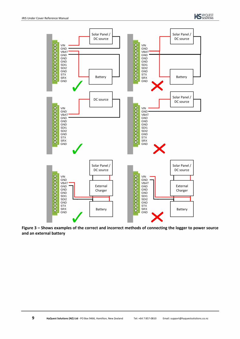
The iRIS can operate solely from the external battery which is charged externally, or you can connect any external dc power source ranging from 8 – 30Vdc, including a solar panel, without requiring an additional solar regulator. The battery charging circuitry utilises a switch mode regulator, employing Maximum Power Point Tracking (MPPT) for maximum efficiency. The external power supply is protected against over-voltage by ultra-fast acting protection devices and a self-resetting semiconductor fuse. The regulator can be configured to change different types of battery chemistry:
• Sealed lead acid (SLA)
• Lithium Ion / Lithium Polymer Batteries
• Custom (user defined) See section 6.3 for more information on configuration of the internal solar regulator.
WARNING A cable length of lesser than 3m is required on the VIN port
WARNING When using the charger feature of the logger an external battery needs to be
attached. The input supply must be connected to VIN and the battery connected to VBAT. When an external charger or DC source is used this must be connected to VBAT and NOT VIN. In this case VIN should be left disconnected. Failure to follow these instructions will cause the power to logger to drop out irregularly and it will reboot.
Signal GND GND Digital Input #1 DI1 Digital Input #2 DI2 Digital Input / Output * DIO Digital Output * DIO Signal GND GND Analogue Input #1 AI1 Analogue Input #1 AI2 Signal GND GND Variable Analogue AO Output ((0-5V or 4-20mA)
iRIS Under Cover Reference Manual
9 HyQuest Solutions (NZ) Ltd - PO Box 9466, Hamilton, New Zealand Tel: +64 7 857-0810 Email: [email protected]
Figure 3 – Shows examples of the correct and incorrect methods of connecting the logger to power source and an external battery
VIN GND VBAT
GND
GND
GND
SDI1
SDI2
GND
STX
SRX
GND
Solar Panel / DC source
Battery
VIN GND VBAT
GND
GND
GND
SDI1
SDI2
GND
STX
SRX
GND
Solar Panel / DC source
Battery
VIN GND VBAT
GND
GND
GND
SDI1
SDI2
GND
STX
SRX
GND
DC source
VIN GND VBAT
GND
GND
GND
SDI1
SDI2
GND
STX
SRX
GND
Solar Panel / DC source
VIN GND VBAT
GND
GND
GND
SDI1
SDI2
GND
STX
SRX
GND
Solar Panel / DC source
Battery
External Charger
VIN GND VBAT
GND
GND
GND
SDI1
SDI2
GND
STX
SRX
GND
Solar Panel / DC source
Battery
External Charger
iRIS Under Cover Reference Manual
10 HyQuest Solutions (NZ) Ltd - PO Box 9466, Hamilton, New Zealand Tel: +64 7 857-0810 Email: [email protected]
4.2.2 Analogue I/O
4.2.2.1 Analogue Inputs
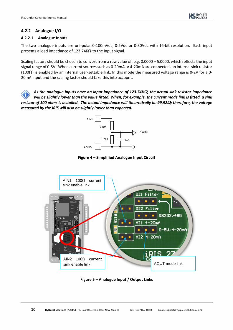
The two analogue inputs are uni-polar 0-100mVdc, 0-5Vdc or 0-30Vdc with 16-bit resolution. Each input
presents a load impedance of 123.74K to the input signal. Scaling factors should be chosen to convert from a raw value of, e.g. 0.0000 – 5.0000, which reflects the input signal range of 0-5V. When current sources such as 0-20mA or 4-20mA are connected, an internal sink resistor
(100) is enabled by an internal user-settable link. In this mode the measured voltage range is 0-2V for a 0-20mA input and the scaling factor should take this into account.
As the analogue inputs have an input impedance of 123.74K, the actual sink resistor impedance will be slightly lower than the value fitted. When, for example, the current mode link is fitted, a sink
resistor of 100 ohms is installed. The actual impedance will theoretically be 99.92; therefore, the voltage measured by the iRIS will also be slightly lower than expected.
Figure 4 – Simplified Analogue Input Circuit
Figure 5 – Analogue Input / Output Links
1nF 3.74K
120K
AGND
AINx
To ADC
AIN2 100Ω current sink enable link
AIN1 100Ω current sink enable link
AOUT mode link
iRIS Under Cover Reference Manual
11 HyQuest Solutions (NZ) Ltd - PO Box 9466, Hamilton, New Zealand Tel: +64 7 857-0810 Email: [email protected]
It is possible to use an external resistor such as a 250 Ω to raise the voltage range measured. I.e. 100Ω will give a working range of 0.4V to 2V, 250Ω will give a range of 1V to 5V. In this case, ensure the internal sink enable link is open. The resistor value in the analogue scaling calculator in iLink will need to be changed to the value actually used. Also a voltage measurement range for the analogue input range needs chosen instead of current.
4.2.2.2 Analogue Output
The iRIS has a single variable analogue output. This may be configured to deliver either a voltage output ranging between 0-5V or a current output ranging from 4-20mA. The output's electrical signal (voltage or current) is link selectable. See Section 5.3.3.1 for details on configuring the analogue output.
4.2.3 Digital I/O
The iRIS has four digital I/O channels which can each be configured as either an input or output. When set as an output, the channel can either supply switched 12V or else act as a pull-down switch for loads with a different supply voltage. If the digital output configuration is set to 0 (Disabled) the channel is by default an input. See Section 5.3.3.1 for details on configuring the digital outputs. 4.2.3.1 Digital Channels as Inputs
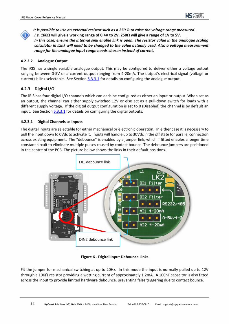
The digital inputs are selectable for either mechanical or electronic operation. In either case it is necessary to pull the input down to 0Vdc to activate it. Inputs will handle up to 30Vdc in the off state for parallel connection across existing equipment. The “debounce” is enabled by a jumper link, which if fitted enables a longer time constant circuit to eliminate multiple pulses caused by contact bounce. The debounce jumpers are positioned in the centre of the PCB. The picture below shows the links in their default positions.
Figure 6 - Digital Input Debounce Links
Fit the jumper for mechanical switching at up to 20Hz. In this mode the input is normally pulled up to 12V
through a 10K resistor providing a wetting current of approximately 1.2mA. A 100nF capacitor is also fitted across the input to provide limited hardware debounce, preventing false triggering due to contact bounce.
DIN2 debounce link
DI1 debounce link

iRIS Under Cover Reference Manual
12 HyQuest Solutions (NZ) Ltd - PO Box 9466, Hamilton, New Zealand Tel: +64 7 857-0810 Email: [email protected]
Remove the appropriate jumper for electronic switching at up to 5kHz. In this mode the input is normally
pulled up to 5V through a 57K resistance, providing a wetting current of approximately 100A. When DIO is used as an input the debouce circuit is permanently connected to the input pin.
Figure 7 – Digital Input Circuit
4.2.3.2 Digital Output2
When the iRIS digital I/O channel is configured as an output it can be operated electrically in one of two ways. Either: Open-drain Pull-down which is capable of sinking up to 100mA at 30Vdc. An integral diode provides transient protection. Typically this output mode can be used to drive a relay or lamp powered by an auxiliary d.c supply (e.g. 12V). In this mode, the negative of the load supply must be connected to one of the iRIS GND terminals.
Although it may appear possible to directly control sensors by switching the sensor negative supply lead using a digital output, this will introduce measurement errors and may possibly damage the sensor. Always use a digital output configured as a switched 12V output to power sensors.
Or: Switched 12V output which is capable of sourcing up to 100mA. Typically this output mode will be used to drive a sensor, relay or lamp powered by the iRIS’s 12V supply.
2 Only available on iRIS Under Cover Pro Version
DIOx
DGND
100nF
JPx
1K
10K
+12V 5V
1nF
IMPORTANT NOTE! In almost all installations where an iRIS is connected in parallel with other equipment to share a common pulse input (e.g. from a flow meter), there has not been a detrimental effect, as the iRIS inputs present a relatively high impedance to the circuit. However, in the event that connecting an iRIS does cause pulse failure, HyQuest Solutions recommend removing the debounce selection link for the appropriate input. This sets the input to electronic switching mode, even if the actual pulse source is a clean contact (reed switch or similar). The debounce jumpers are located in the center of the PCB and can be accessed once the front cover is opened. See Figure 6 - Digital Input Debounce Links above. Hint: When removing a jumper, simply fit it to only one pin of the connector to avoid it being lost.
To internal logic circuitry
iRIS Under Cover Reference Manual
13 HyQuest Solutions (NZ) Ltd - PO Box 9466, Hamilton, New Zealand Tel: +64 7 857-0810 Email: [email protected]
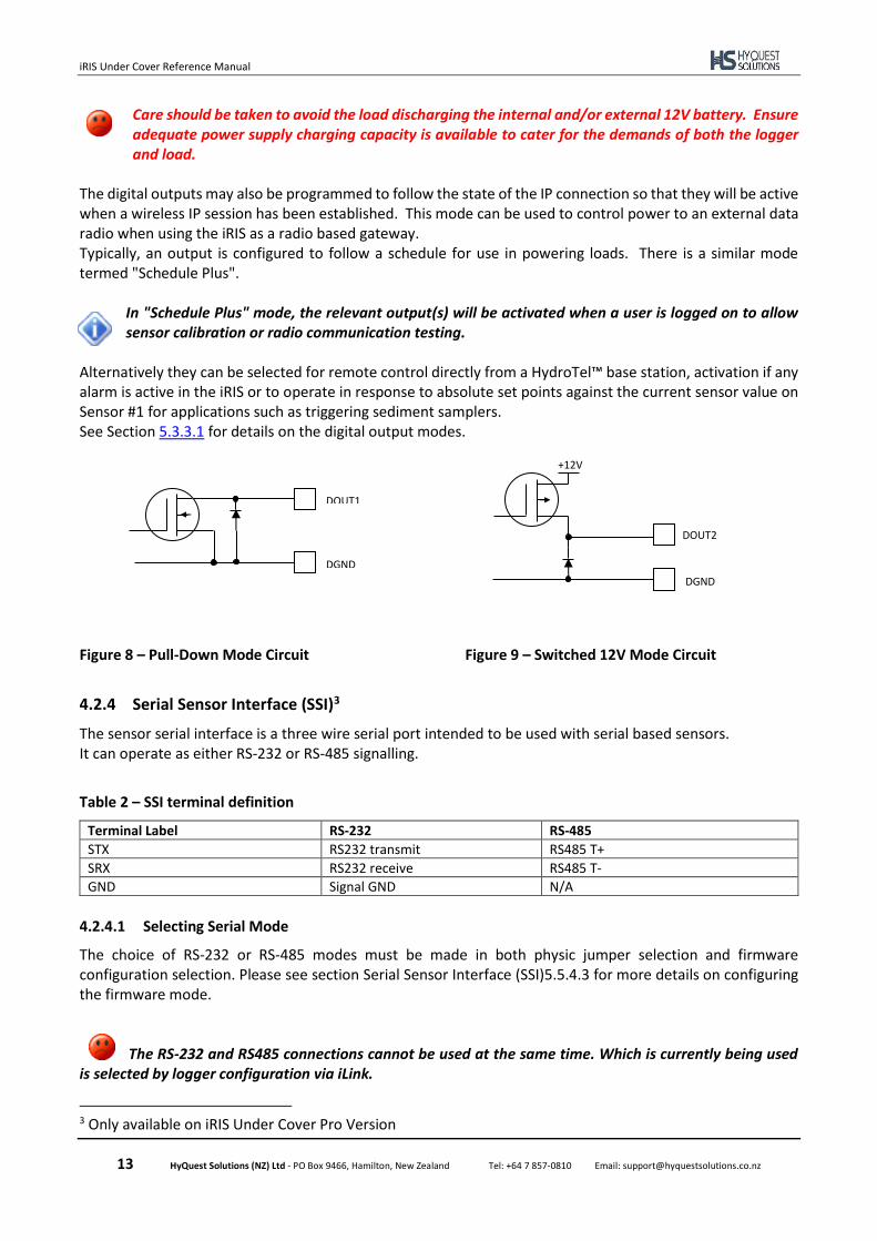
Care should be taken to avoid the load discharging the internal and/or external 12V battery. Ensure adequate power supply charging capacity is available to cater for the demands of both the logger and load.
The digital outputs may also be programmed to follow the state of the IP connection so that they will be active when a wireless IP session has been established. This mode can be used to control power to an external data radio when using the iRIS as a radio based gateway. Typically, an output is configured to follow a schedule for use in powering loads. There is a similar mode termed "Schedule Plus".
In "Schedule Plus" mode, the relevant output(s) will be activated when a user is logged on to allow sensor calibration or radio communication testing.
Alternatively they can be selected for remote control directly from a HydroTel™ base station, activation if any alarm is active in the iRIS or to operate in response to absolute set points against the current sensor value on Sensor #1 for applications such as triggering sediment samplers. See Section 5.3.3.1 for details on the digital output modes.
Figure 8 – Pull-Down Mode Circuit
Figure 9 – Switched 12V Mode Circuit
4.2.4 Serial Sensor Interface (SSI)3
The sensor serial interface is a three wire serial port intended to be used with serial based sensors. It can operate as either RS-232 or RS-485 signalling.
Table 2 – SSI terminal definition
Terminal Label RS-232 RS-485
STX RS232 transmit RS485 T+
SRX RS232 receive RS485 T-
GND Signal GND N/A
4.2.4.1 Selecting Serial Mode
The choice of RS-232 or RS-485 modes must be made in both physic jumper selection and firmware configuration selection. Please see section Serial Sensor Interface (SSI)5.5.4.3 for more details on configuring the firmware mode.
The RS-232 and RS485 connections cannot be used at the same time. Which is currently being used
is selected by logger configuration via iLink.
3 Only available on iRIS Under Cover Pro Version
DOUT1
DGND
DOUT2
+12V
DGND
iRIS Under Cover Reference Manual
14 HyQuest Solutions (NZ) Ltd - PO Box 9466, Hamilton, New Zealand Tel: +64 7 857-0810 Email: [email protected]
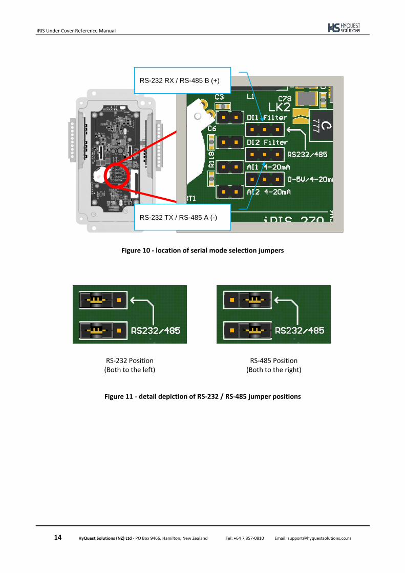
Figure 10 - location of serial mode selection jumpers
Figure 11 - detail depiction of RS-232 / RS-485 jumper positions
RS-232 TX / RS-485 A (-)
RS-232 RX / RS-485 B (+)
RS-232 Position (Both to the left)
RS-485 Position (Both to the right)
iRIS Under Cover Reference Manual
15 HyQuest Solutions (NZ) Ltd - PO Box 9466, Hamilton, New Zealand Tel: +64 7 857-0810 Email: [email protected]
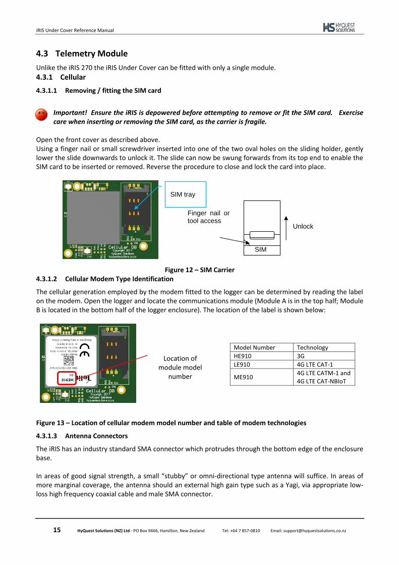
4.3 Telemetry Module
Unlike the iRIS 270 the iRIS Under Cover can be fitted with only a single module.
4.3.1 Cellular
4.3.1.1 Removing / fitting the SIM card
Important! Ensure the iRIS is depowered before attempting to remove or fit the SIM card. Exercise care when inserting or removing the SIM card, as the carrier is fragile.
Open the front cover as described above. Using a finger nail or small screwdriver inserted into one of the two oval holes on the sliding holder, gently lower the slide downwards to unlock it. The slide can now be swung forwards from its top end to enable the SIM card to be inserted or removed. Reverse the procedure to close and lock the card into place.
Figure 12 – SIM Carrier 4.3.1.2 Cellular Modem Type Identification
The cellular generation employed by the modem fitted to the logger can be determined by reading the label on the modem. Open the logger and locate the communications module (Module A is in the top half; Module B is located in the bottom half of the logger enclosure). The location of the label is shown below:
Model Number Technology
HE910 3G
LE910 4G LTE CAT-1
ME910 4G LTE CATM-1 and 4G LTE CAT-NBIoT
Figure 13 – Location of cellular modem model number and table of modem technologies
4.3.1.3 Antenna Connectors
The iRIS has an industry standard SMA connector which protrudes through the bottom edge of the enclosure base. In areas of good signal strength, a small “stubby” or omni-directional type antenna will suffice. In areas of more marginal coverage, the antenna should an external high gain type such as a Yagi, via appropriate low-loss high frequency coaxial cable and male SMA connector.
Location of module model
number
SIM tray
Unlock
Finger nail or tool access
SIM

iRIS Under Cover Reference Manual
16 HyQuest Solutions (NZ) Ltd - PO Box 9466, Hamilton, New Zealand Tel: +64 7 857-0810 Email: [email protected]
Figure 14 – antenna connector view
iRIS Under Cover Reference Manual
17 HyQuest Solutions (NZ) Ltd - PO Box 9466, Hamilton, New Zealand Tel: +64 7 857-0810 Email: [email protected]
5 Configuration
The iRIS configuration is done by iLink 2012 or HydroTel. This description assumes a computer running the Microsoft® Windows® operating system is being used and all examples relate to the configuration tool in iLink 2012. iLink 2012 Mobile version can also be used to configure the iRIS,
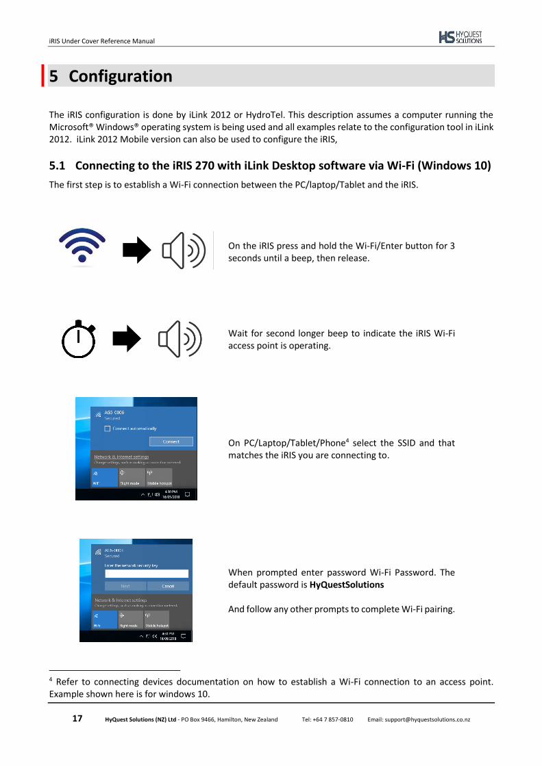
5.1 Connecting to the iRIS 270 with iLink Desktop software via Wi-Fi (Windows 10)
The first step is to establish a Wi-Fi connection between the PC/laptop/Tablet and the iRIS.
On the iRIS press and hold the Wi-Fi/Enter button for 3 seconds until a beep, then release.
Wait for second longer beep to indicate the iRIS Wi-Fi access point is operating.
On PC/Laptop/Tablet/Phone4 select the SSID and that matches the iRIS you are connecting to.
When prompted enter password Wi-Fi Password. The default password is HyQuestSolutions And follow any other prompts to complete Wi-Fi pairing.
4 Refer to connecting devices documentation on how to establish a Wi-Fi connection to an access point. Example shown here is for windows 10.
iRIS Under Cover Reference Manual
18 HyQuest Solutions (NZ) Ltd - PO Box 9466, Hamilton, New Zealand Tel: +64 7 857-0810 Email: [email protected]
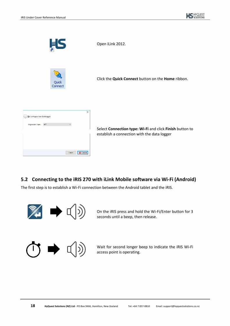
Open iLink 2012.
Click the Quick Connect button on the Home ribbon.
Select Connection type: Wi-Fi and click Finish button to establish a connection with the data logger
5.2 Connecting to the iRIS 270 with iLink Mobile software via Wi-Fi (Android)
The first step is to establish a Wi-Fi connection between the Android tablet and the iRIS.
On the iRIS press and hold the Wi-Fi/Enter button for 3 seconds until a beep, then release.
Wait for second longer beep to indicate the iRIS Wi-Fi access point is operating.
iRIS Under Cover Reference Manual
19 HyQuest Solutions (NZ) Ltd - PO Box 9466, Hamilton, New Zealand Tel: +64 7 857-0810 Email: [email protected]
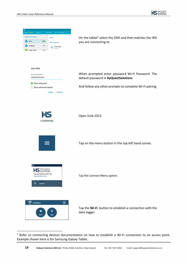
On the tablet5 select the SSID and that matches the iRIS you are connecting to.
When prompted enter password Wi-Fi Password. The default password is HyQuestSolutions And follow any other prompts to complete Wi-Fi pairing.
Open iLink 2012.
Tap on the menu button in the top left hand corner.
Tap the Connect Menu option.
Tap the Wi-Fi button to establish a connection with the data logger
5 Refer to connecting devices documentation on how to establish a Wi-Fi connection to an access point. Example shown here is for Samsung Galaxy Tablet.
iRIS Under Cover Reference Manual
20 HyQuest Solutions (NZ) Ltd - PO Box 9466, Hamilton, New Zealand Tel: +64 7 857-0810 Email: [email protected]
5.3 Turn off Wi-Fi Access Point
The Wi-Fi access point will turn itself off after a predetermined time (see section 5.5.4.1) or it can be turned off on demand via SMS command (see section 6.4.1) or via the Keypad by following the instructions:
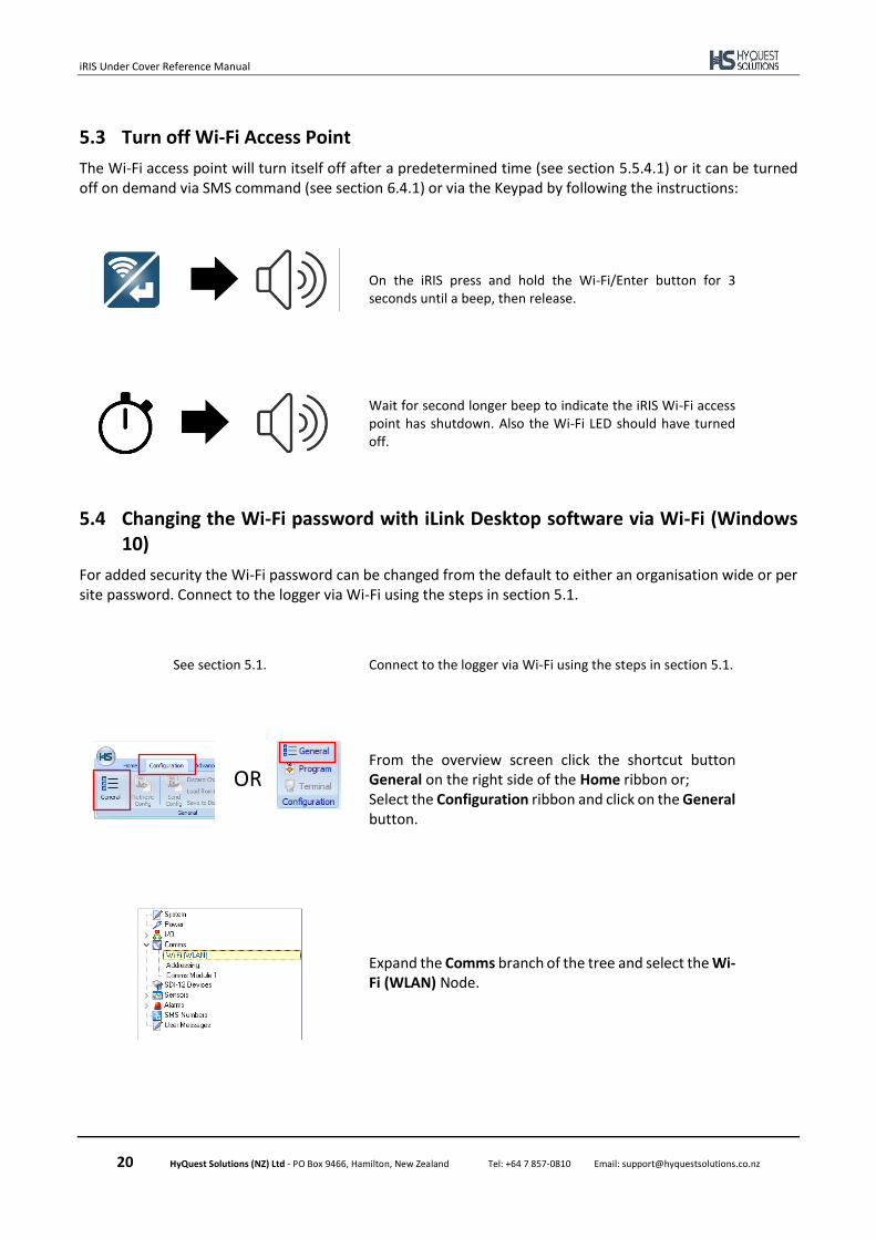
On the iRIS press and hold the Wi-Fi/Enter button for 3 seconds until a beep, then release.
Wait for second longer beep to indicate the iRIS Wi-Fi access point has shutdown. Also the Wi-Fi LED should have turned off.
5.4 Changing the Wi-Fi password with iLink Desktop software via Wi-Fi (Windows 10)
For added security the Wi-Fi password can be changed from the default to either an organisation wide or per site password. Connect to the logger via Wi-Fi using the steps in section 5.1.
See section 5.1. Connect to the logger via Wi-Fi using the steps in section 5.1.
From the overview screen click the shortcut button General on the right side of the Home ribbon or; Select the Configuration ribbon and click on the General button.
Expand the Comms branch of the tree and select the Wi-Fi (WLAN) Node.
OR
iRIS Under Cover Reference Manual
21 HyQuest Solutions (NZ) Ltd - PO Box 9466, Hamilton, New Zealand Tel: +64 7 857-0810 Email: [email protected]
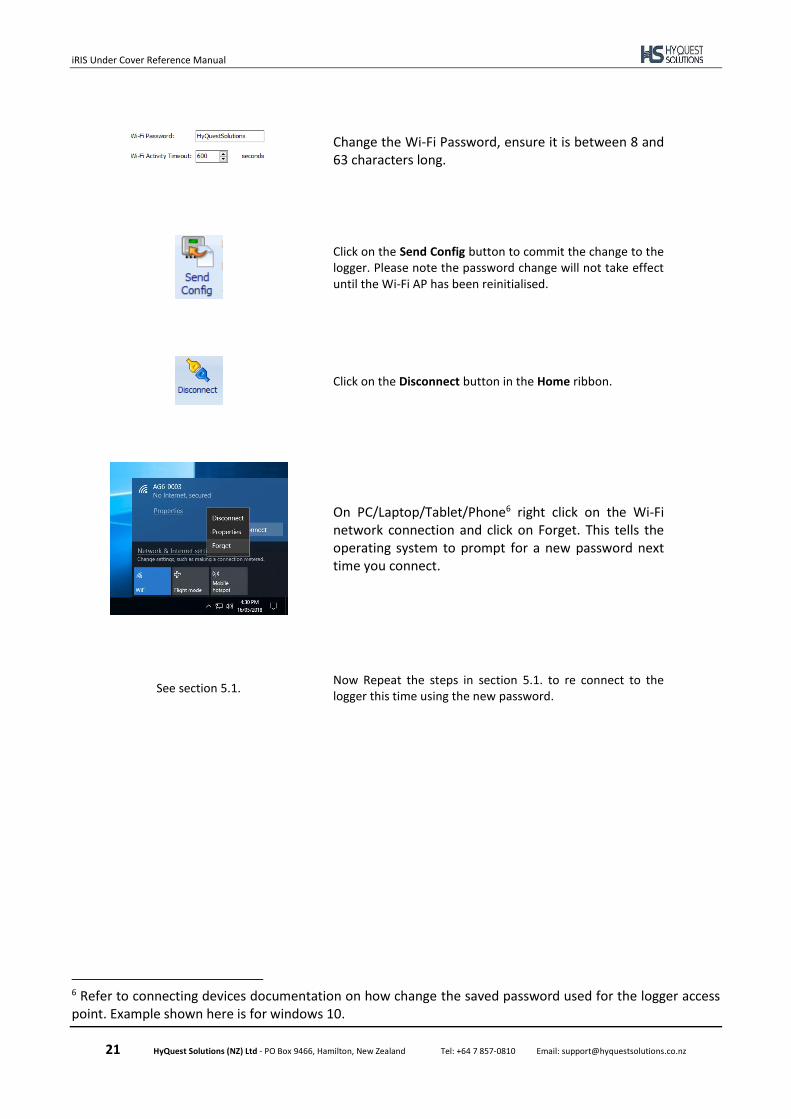
Change the Wi-Fi Password, ensure it is between 8 and 63 characters long.
Click on the Send Config button to commit the change to the logger. Please note the password change will not take effect until the Wi-Fi AP has been reinitialised.
Click on the Disconnect button in the Home ribbon.
On PC/Laptop/Tablet/Phone6 right click on the Wi-Fi network connection and click on Forget. This tells the operating system to prompt for a new password next time you connect.
See section 5.1. Now Repeat the steps in section 5.1. to re connect to the logger this time using the new password.
6 Refer to connecting devices documentation on how change the saved password used for the logger access point. Example shown here is for windows 10.
iRIS Under Cover Reference Manual
22 HyQuest Solutions (NZ) Ltd - PO Box 9466, Hamilton, New Zealand Tel: +64 7 857-0810 Email: [email protected]
5.5 Configuration Menus
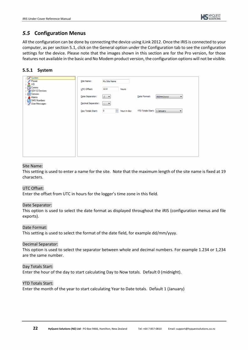
All the configuration can be done by connecting the device using iLink 2012. Once the iRIS is connected to your computer, as per section 5.1, click on the General option under the Configuration tab to see the configuration settings for the device. Please note that the images shown in this section are for the Pro version, for those features not available in the basic and No Modem product version, the configuration options will not be visible.
5.5.1 System
Site Name: This setting is used to enter a name for the site. Note that the maximum length of the site name is fixed at 19 characters. UTC Offset: Enter the offset from UTC in hours for the logger’s time zone in this field. Date Separator: This option is used to select the date format as displayed throughout the iRIS (configuration menus and file exports). Date Format: This setting is used to select the format of the date field, for example dd/mm/yyyy. Decimal Separator: This option is used to select the separator between whole and decimal numbers. For example 1.234 or 1,234 are the same number. Day Totals Start: Enter the hour of the day to start calculating Day to Now totals. Default 0 (midnight). YTD Totals Start: Enter the month of the year to start calculating Year to Date totals. Default 1 (January)
iRIS Under Cover Reference Manual
23 HyQuest Solutions (NZ) Ltd - PO Box 9466, Hamilton, New Zealand Tel: +64 7 857-0810 Email: [email protected]
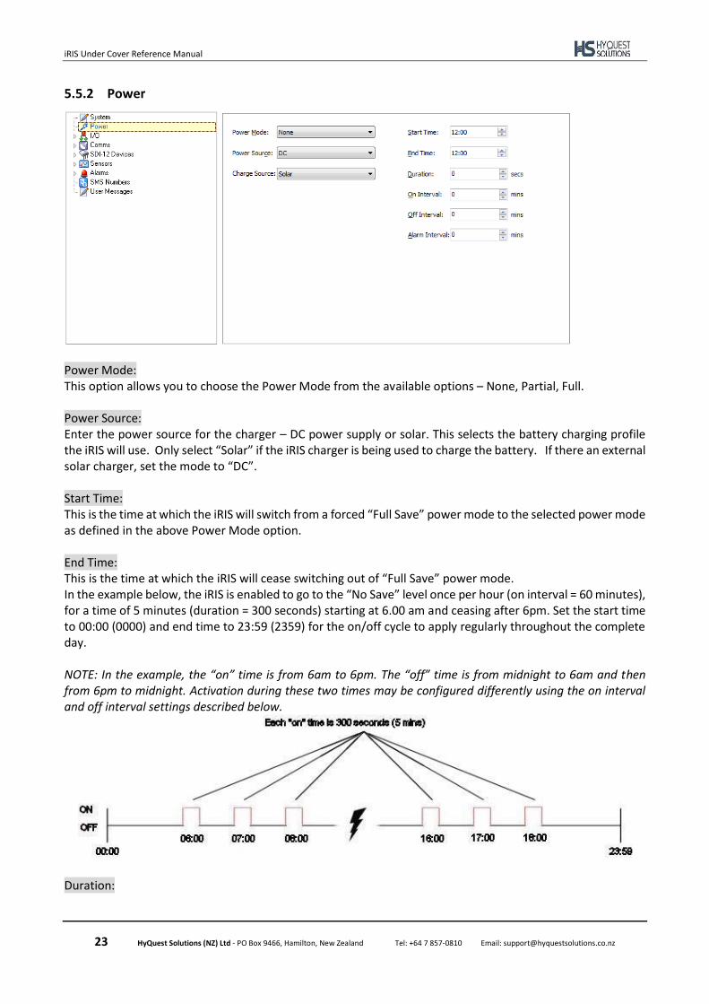
5.5.2 Power
Power Mode: This option allows you to choose the Power Mode from the available options – None, Partial, Full. Power Source: Enter the power source for the charger – DC power supply or solar. This selects the battery charging profile the iRIS will use. Only select “Solar” if the iRIS charger is being used to charge the battery. If there an external solar charger, set the mode to “DC”. Start Time: This is the time at which the iRIS will switch from a forced “Full Save” power mode to the selected power mode as defined in the above Power Mode option. End Time: This is the time at which the iRIS will cease switching out of “Full Save” power mode. In the example below, the iRIS is enabled to go to the “No Save” level once per hour (on interval = 60 minutes), for a time of 5 minutes (duration = 300 seconds) starting at 6.00 am and ceasing after 6pm. Set the start time to 00:00 (0000) and end time to 23:59 (2359) for the on/off cycle to apply regularly throughout the complete day. NOTE: In the example, the “on” time is from 6am to 6pm. The “off” time is from midnight to 6am and then from 6pm to midnight. Activation during these two times may be configured differently using the on interval and off interval settings described below.
Duration:
iRIS Under Cover Reference Manual
24 HyQuest Solutions (NZ) Ltd - PO Box 9466, Hamilton, New Zealand Tel: +64 7 857-0810 Email: [email protected]
Enter the length of time in seconds that you want the iRIS to maintain the modem in the selected power mode. The minimum value for this setting is 60 seconds. On Interval: This is the length of time in minutes between each successive power mode change when the time is in the “on” period. i.e. between the start and end times. Off Interval This is the length of time in minutes between each successive power mode change when the time is in “off” period. i.e. before the start time or after the end time. This setting will normally be 0 (no activity in the off period), but this option does allow a different activation rate to be configured if required. Alarm Interval: Enter the length of time in minutes between each successive power mode change – when there are one or more active alarms in the iRIS.
5.5.3 I/O Configuration
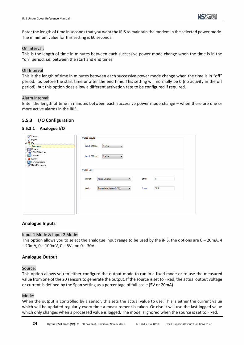
5.5.3.1 Analogue I/O
Analogue Inputs Input 1 Mode & Input 2 Mode: This option allows you to select the analogue input range to be used by the iRIS, the options are 0 – 20mA, 4 – 20mA, 0 – 100mV, 0 – 5V and 0 – 30V.
Analogue Output Source: This option allows you to either configure the output mode to run in a fixed mode or to use the measured value from one of the 20 sensors to generate the output. If the source is set to Fixed, the actual output voltage or current is defined by the Span setting as a percentage of full-scale (5V or 20mA) Mode: When the output is controlled by a sensor, this sets the actual value to use. This is either the current value which will be updated regularly every time a measurement is taken. Or else it will use the last logged value which only changes when a processed value is logged. The mode is ignored when the source is set to Fixed.
iRIS Under Cover Reference Manual
25 HyQuest Solutions (NZ) Ltd - PO Box 9466, Hamilton, New Zealand Tel: +64 7 857-0810 Email: [email protected]
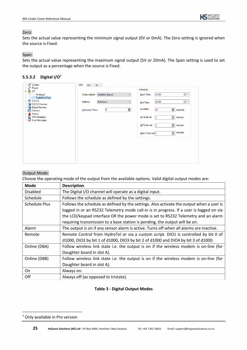
Zero: Sets the actual value representing the minimum signal output (0V or 0mA). The Zero setting is ignored when the source is Fixed. Span: Sets the actual value representing the maximum signal output (5V or 20mA). The Span setting is used to set the output as a percentage when the source is Fixed. 5.5.3.2 Digital I/O7
Output Mode: Choose the operating mode of the output from the available options. Valid digital output modes are:
Table 3 - Digital Output Modes
7 Only available in Pro version
Mode Description
Disabled The Digital I/O channel will operate as a digital input.
Schedule Follows the schedule as defined by the settings.
Schedule Plus Follows the schedule as defined by the settings. Also activate the output when a user is
logged in or an RS232 Telemetry mode call-in is in progress. If a user is logged on via
the LCD/keypad interface OR the power mode is set to RS232 Telemetry and an alarm
requiring transmission to a base station is pending, the output will be on.
Alarm The output is on if any sensor alarm is active. Turns off when all alarms are inactive.
Remote Remote Control from HydroTel or via a custom script. DIO1 is controlled by bit 0 of
d1000, DIO2 by bit 1 of d1000, DIO3 by bit 2 of d1000 and DIO4 by bit 3 of d1000.
Online (DBA) Follow wireless link state i.e. the output is on if the wireless modem is on-line (for
Daughter board in slot A).
Online (DBB) Follow wireless link state i.e. the output is on if the wireless modem is on-line (for
Daughter board in slot A).
On Always on.
Off Always off (as opposed to tristate).
iRIS Under Cover Reference Manual
26 HyQuest Solutions (NZ) Ltd - PO Box 9466, Hamilton, New Zealand Tel: +64 7 857-0810 Email: [email protected]
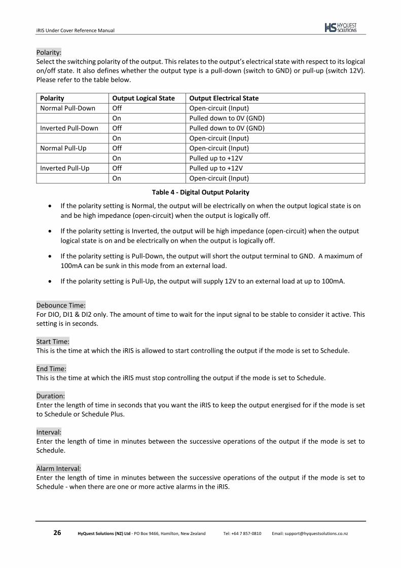
Polarity: Select the switching polarity of the output. This relates to the output’s electrical state with respect to its logical on/off state. It also defines whether the output type is a pull-down (switch to GND) or pull-up (switch 12V). Please refer to the table below.
Polarity Output Logical State Output Electrical State
Normal Pull-Down Off Open-circuit (Input)
On Pulled down to 0V (GND)
Inverted Pull-Down Off Pulled down to 0V (GND)
On Open-circuit (Input)
Normal Pull-Up Off Open-circuit (Input)
On Pulled up to +12V
Inverted Pull-Up Off Pulled up to +12V
On Open-circuit (Input)
Table 4 - Digital Output Polarity
• If the polarity setting is Normal, the output will be electrically on when the output logical state is on
and be high impedance (open-circuit) when the output is logically off.
• If the polarity setting is Inverted, the output will be high impedance (open-circuit) when the output
logical state is on and be electrically on when the output is logically off.
• If the polarity setting is Pull-Down, the output will short the output terminal to GND. A maximum of
100mA can be sunk in this mode from an external load.
• If the polarity setting is Pull-Up, the output will supply 12V to an external load at up to 100mA.
Debounce Time: For DIO, DI1 & DI2 only. The amount of time to wait for the input signal to be stable to consider it active. This setting is in seconds. Start Time: This is the time at which the iRIS is allowed to start controlling the output if the mode is set to Schedule. End Time: This is the time at which the iRIS must stop controlling the output if the mode is set to Schedule. Duration: Enter the length of time in seconds that you want the iRIS to keep the output energised for if the mode is set to Schedule or Schedule Plus. Interval: Enter the length of time in minutes between the successive operations of the output if the mode is set to Schedule. Alarm Interval: Enter the length of time in minutes between the successive operations of the output if the mode is set to Schedule - when there are one or more active alarms in the iRIS.
iRIS Under Cover Reference Manual
27 HyQuest Solutions (NZ) Ltd - PO Box 9466, Hamilton, New Zealand Tel: +64 7 857-0810 Email: [email protected]
5.5.4 Comms
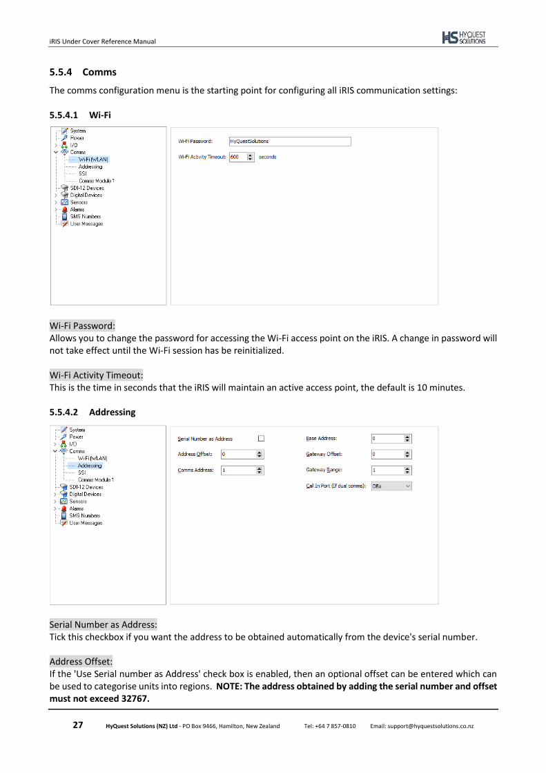
The comms configuration menu is the starting point for configuring all iRIS communication settings: 5.5.4.1 Wi-Fi
Wi-Fi Password: Allows you to change the password for accessing the Wi-Fi access point on the iRIS. A change in password will not take effect until the Wi-Fi session has be reinitialized. Wi-Fi Activity Timeout: This is the time in seconds that the iRIS will maintain an active access point, the default is 10 minutes. 5.5.4.2 Addressing
Serial Number as Address: Tick this checkbox if you want the address to be obtained automatically from the device's serial number. Address Offset: If the 'Use Serial number as Address' check box is enabled, then an optional offset can be entered which can be used to categorise units into regions. NOTE: The address obtained by adding the serial number and offset must not exceed 32767.
iRIS Under Cover Reference Manual
28 HyQuest Solutions (NZ) Ltd - PO Box 9466, Hamilton, New Zealand Tel: +64 7 857-0810 Email: [email protected]
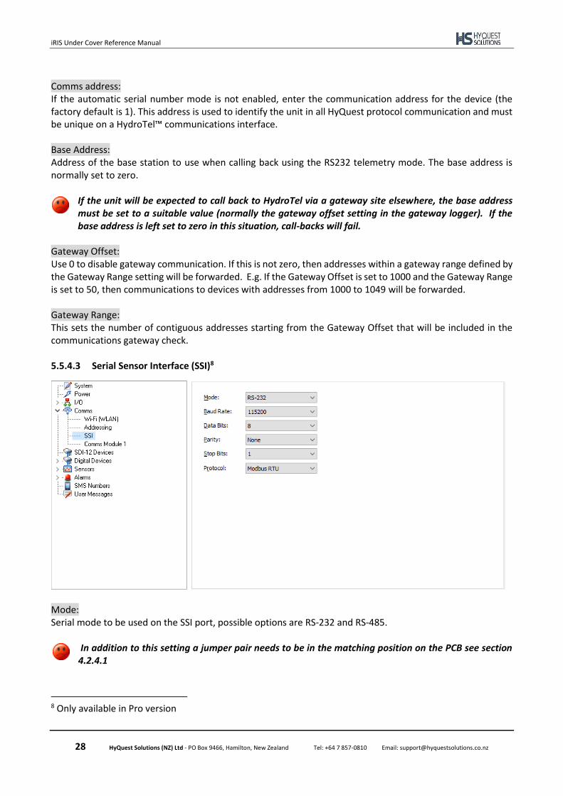
Comms address: If the automatic serial number mode is not enabled, enter the communication address for the device (the factory default is 1). This address is used to identify the unit in all HyQuest protocol communication and must be unique on a HydroTel™ communications interface. Base Address: Address of the base station to use when calling back using the RS232 telemetry mode. The base address is normally set to zero.
If the unit will be expected to call back to HydroTel via a gateway site elsewhere, the base address must be set to a suitable value (normally the gateway offset setting in the gateway logger). If the base address is left set to zero in this situation, call-backs will fail.
Gateway Offset: Use 0 to disable gateway communication. If this is not zero, then addresses within a gateway range defined by the Gateway Range setting will be forwarded. E.g. If the Gateway Offset is set to 1000 and the Gateway Range is set to 50, then communications to devices with addresses from 1000 to 1049 will be forwarded. Gateway Range: This sets the number of contiguous addresses starting from the Gateway Offset that will be included in the communications gateway check. 5.5.4.3 Serial Sensor Interface (SSI)8
Mode: Serial mode to be used on the SSI port, possible options are RS-232 and RS-485.
In addition to this setting a jumper pair needs to be in the matching position on the PCB see section 4.2.4.1
8 Only available in Pro version
iRIS Under Cover Reference Manual
29 HyQuest Solutions (NZ) Ltd - PO Box 9466, Hamilton, New Zealand Tel: +64 7 857-0810 Email: [email protected]
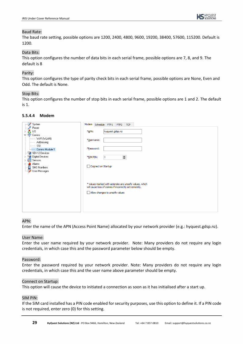
Baud Rate: The baud rate setting, possible options are 1200, 2400, 4800, 9600, 19200, 38400, 57600, 115200. Default is
1200.
Data Bits: This option configures the number of data bits in each serial frame, possible options are 7, 8, and 9. The
default is 8
Parity: This option configures the type of parity check bits in each serial frame, possible options are None, Even and
Odd. The default is None.
Stop Bits: This option configures the number of stop bits in each serial frame, possible options are 1 and 2. The default is 1. 5.5.4.4 Modem
APN: Enter the name of the APN (Access Point Name) allocated by your network provider (e.g.: hyquest.gdsp.nz). User Name: Enter the user name required by your network provider. Note: Many providers do not require any login credentials, in which case this and the password parameter below should be empty. Password: Enter the password required by your network provider. Note: Many providers do not require any login credentials, in which case this and the user name above parameter should be empty. Connect on Startup: This option will cause the device to initiated a connection as soon as it has initialised after a start up. SIM PIN: If the SIM card installed has a PIN code enabled for security purposes, use this option to define it. If a PIN code is not required, enter zero (0) for this setting.
iRIS Under Cover Reference Manual
30 HyQuest Solutions (NZ) Ltd - PO Box 9466, Hamilton, New Zealand Tel: +64 7 857-0810 Email: [email protected]
If a SIM PIN is required and an incorrect PIN is entered, the unit will not operate correctly. Also, if the SIM PIN is set incorrectly, repeated attempts by the iRIS to log-on may result in the SIM card becoming locked out. This situation will require knowledge of the SIM’s PIN Unlock Key (PUK) and/or contacting the SIM provider for unlock details.
Allow Changes to Unsafe Values: The APN, Username and Password are marked as unsafe values, which may cause loss of comms if incorrectly set remotely. If you want to edit these columns, the option "Allow changes to unsafe values" should be enabled. 5.5.4.5 Schedule
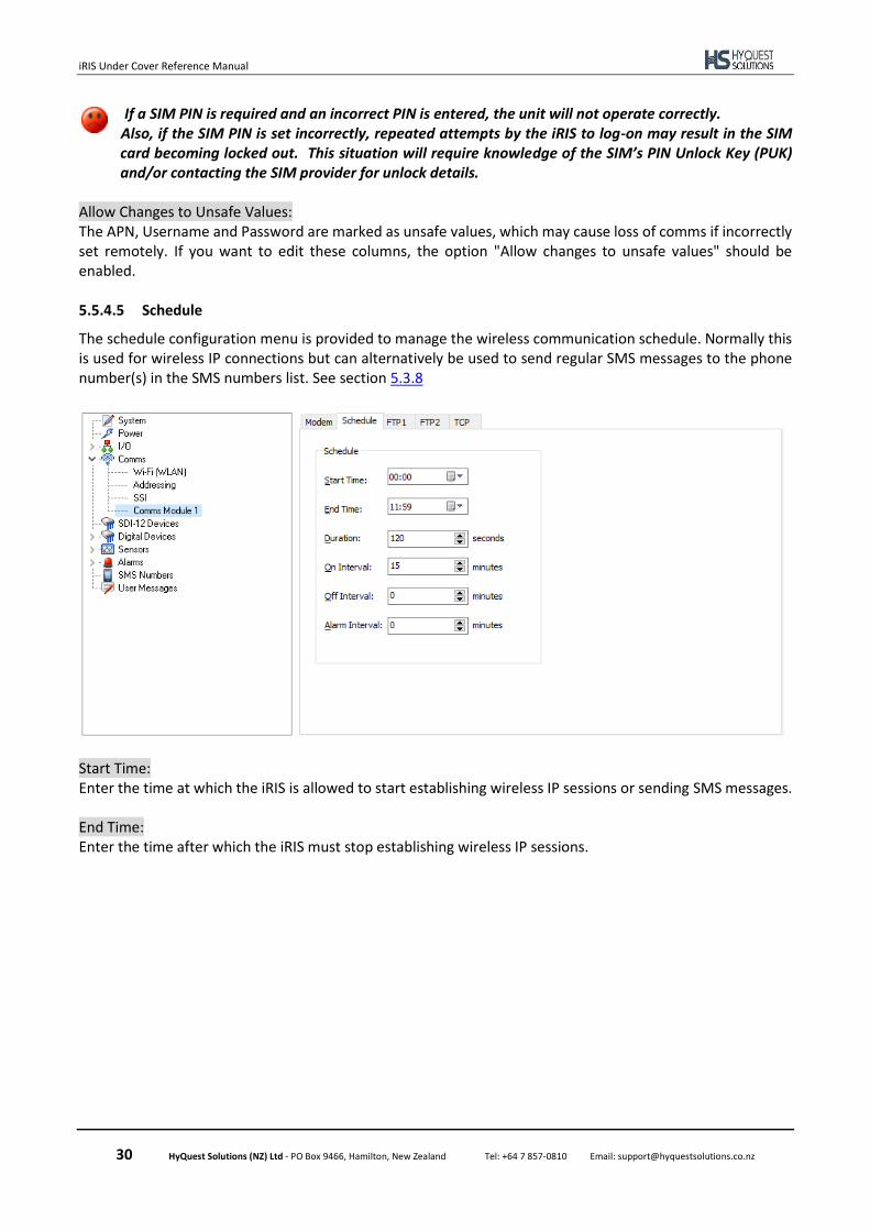
The schedule configuration menu is provided to manage the wireless communication schedule. Normally this is used for wireless IP connections but can alternatively be used to send regular SMS messages to the phone number(s) in the SMS numbers list. See section 5.3.8
Start Time: Enter the time at which the iRIS is allowed to start establishing wireless IP sessions or sending SMS messages. End Time: Enter the time after which the iRIS must stop establishing wireless IP sessions.
iRIS Under Cover Reference Manual
31 HyQuest Solutions (NZ) Ltd - PO Box 9466, Hamilton, New Zealand Tel: +64 7 857-0810 Email: [email protected]
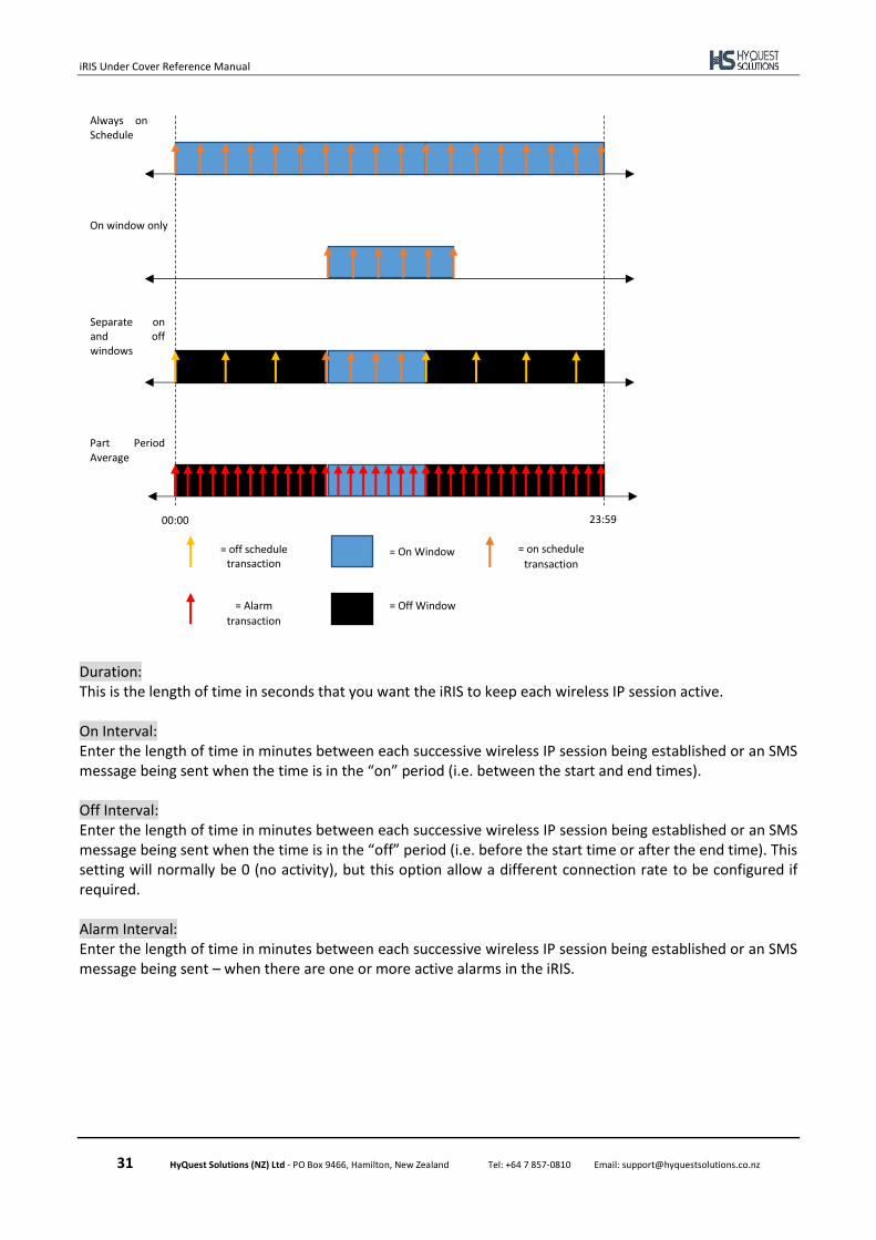
Duration: This is the length of time in seconds that you want the iRIS to keep each wireless IP session active. On Interval: Enter the length of time in minutes between each successive wireless IP session being established or an SMS message being sent when the time is in the “on” period (i.e. between the start and end times). Off Interval: Enter the length of time in minutes between each successive wireless IP session being established or an SMS message being sent when the time is in the “off” period (i.e. before the start time or after the end time). This setting will normally be 0 (no activity), but this option allow a different connection rate to be configured if required. Alarm Interval: Enter the length of time in minutes between each successive wireless IP session being established or an SMS message being sent – when there are one or more active alarms in the iRIS.
Always on Schedule
On window only
Separate on and off windows
Part Period Average
= off schedule transaction
= On Window = on schedule
transaction
00:00 23:59
= Alarm
transaction = Off Window
iRIS Under Cover Reference Manual
32 HyQuest Solutions (NZ) Ltd - PO Box 9466, Hamilton, New Zealand Tel: +64 7 857-0810 Email: [email protected]
5.5.4.6 Cellular Modem - FTP 1 & FTP 2
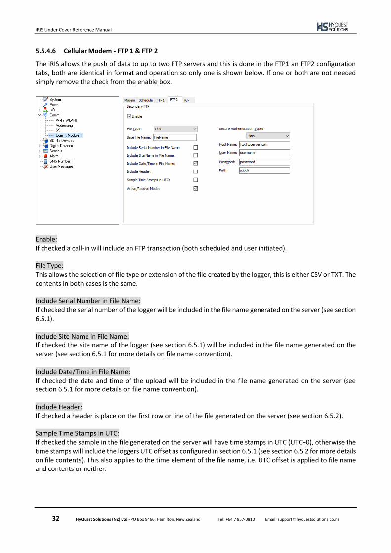
The iRIS allows the push of data to up to two FTP servers and this is done in the FTP1 an FTP2 configuration tabs, both are identical in format and operation so only one is shown below. If one or both are not needed simply remove the check from the enable box.
Enable: If checked a call-in will include an FTP transaction (both scheduled and user initiated). File Type: This allows the selection of file type or extension of the file created by the logger, this is either CSV or TXT. The contents in both cases is the same. Include Serial Number in File Name: If checked the serial number of the logger will be included in the file name generated on the server (see section 6.5.1). Include Site Name in File Name: If checked the site name of the logger (see section 6.5.1) will be included in the file name generated on the server (see section 6.5.1 for more details on file name convention). Include Date/Time in File Name: If checked the date and time of the upload will be included in the file name generated on the server (see section 6.5.1 for more details on file name convention). Include Header: If checked a header is place on the first row or line of the file generated on the server (see section 6.5.2). Sample Time Stamps in UTC: If checked the sample in the file generated on the server will have time stamps in UTC (UTC+0), otherwise the time stamps will include the loggers UTC offset as configured in section 6.5.1 (see section 6.5.2 for more details on file contents). This also applies to the time element of the file name, i.e. UTC offset is applied to file name and contents or neither.
iRIS Under Cover Reference Manual
33 HyQuest Solutions (NZ) Ltd - PO Box 9466, Hamilton, New Zealand Tel: +64 7 857-0810 Email: [email protected]
Active/Passive Mode: If checked the FTP transaction will use Passive mode otherwise Passive mode is used. Passive Mode is recommended for most cases. Secure Authentication Type: This option selects the FTP transaction type authentication type, there are three options:
• Plain – the FTP transaction is in plain text, including user name and password.
• FTPS – uses a secure TLS (Transport Layer Security) to encrypt the FTP transaction, including user name and password.
• FTPS with pain fall back – the logger will attempt to make an FTPS connection with the server, if the server does not support FTPS or there is a problem it will fall back to plain mode.
Host Name Enter the host name of the FTP server to upload files to, this can be a URL or IP address. User Name Enter the user name required to login to the FTP server. Password Enter the password required to login to the FTP server. Path Enter the sub-folder path (if required) on the FTP server. 5.5.4.7 TCP
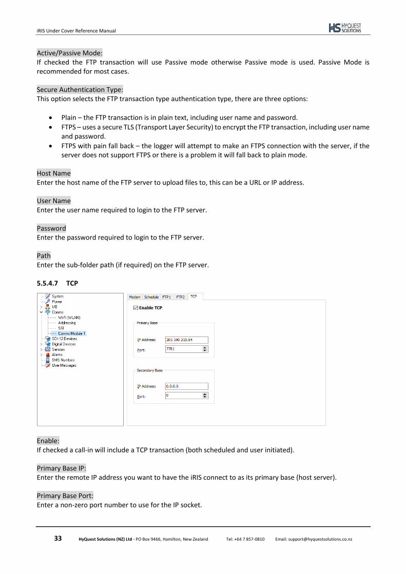
Enable: If checked a call-in will include a TCP transaction (both scheduled and user initiated). Primary Base IP: Enter the remote IP address you want to have the iRIS connect to as its primary base (host server). Primary Base Port: Enter a non-zero port number to use for the IP socket.
iRIS Under Cover Reference Manual
34 HyQuest Solutions (NZ) Ltd - PO Box 9466, Hamilton, New Zealand Tel: +64 7 857-0810 Email: [email protected]
Secondary Base IP: Enter the optional secondary base remote IP address that you will connect to. NOTE: to disable this feature set the IP address to zero Secondary Base Port: Enter the remote port number for the optional secondary base. NOTE: to disable this feature set the IP address to zero
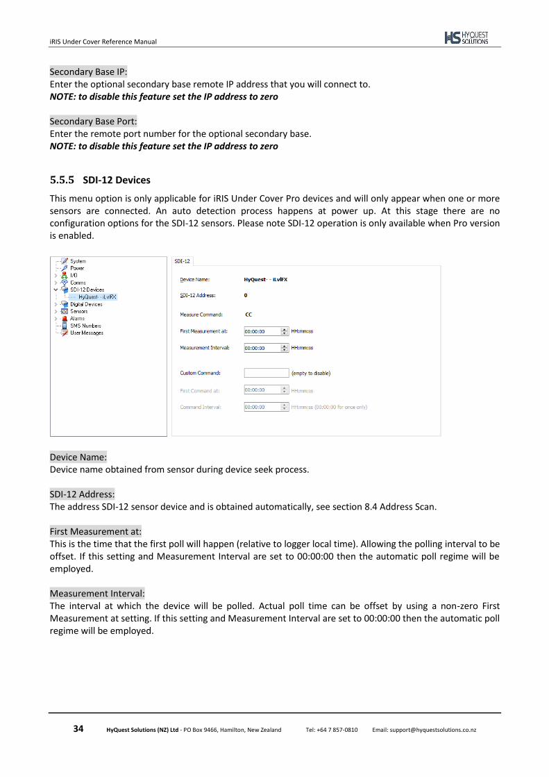
5.5.5 SDI-12 Devices
This menu option is only applicable for iRIS Under Cover Pro devices and will only appear when one or more sensors are connected. An auto detection process happens at power up. At this stage there are no configuration options for the SDI-12 sensors. Please note SDI-12 operation is only available when Pro version is enabled.
Device Name: Device name obtained from sensor during device seek process. SDI-12 Address: The address SDI-12 sensor device and is obtained automatically, see section 8.4 Address Scan. First Measurement at: This is the time that the first poll will happen (relative to logger local time). Allowing the polling interval to be offset. If this setting and Measurement Interval are set to 00:00:00 then the automatic poll regime will be employed. Measurement Interval: The interval at which the device will be polled. Actual poll time can be offset by using a non-zero First Measurement at setting. If this setting and Measurement Interval are set to 00:00:00 then the automatic poll regime will be employed.
iRIS Under Cover Reference Manual
35 HyQuest Solutions (NZ) Ltd - PO Box 9466, Hamilton, New Zealand Tel: +64 7 857-0810 Email: [email protected]
Custom Command: This is an optional command that can be issued on a separate schedule to the poll for measurements schedule. The command can be any SDI-12 command, without the address or closing exclamation mark (!), these are automatically added by the logger. Example of use of this function are, to perform a wipe of the sensor lens or reset a running total. If this command is blank then the associated schedule will not have an effect. First Command at: This is the time that the first custom command will be issued (relative to logger local time). Allowing the custom command issuing interval to be offset. If this setting and Command Interval are set to 00:00:00 then the custom commands will not be issued. Command Interval: The interval at which the custom command will be issued. Actual command issue time can be offset by using a non-zero First Measurement at setting. If this setting is set to 00:00:00 and the First Command at setting is not 00:00:00, the custom command will be issued once at the time defined by the First Measurement at setting.
5.5.6 Digital Devices9
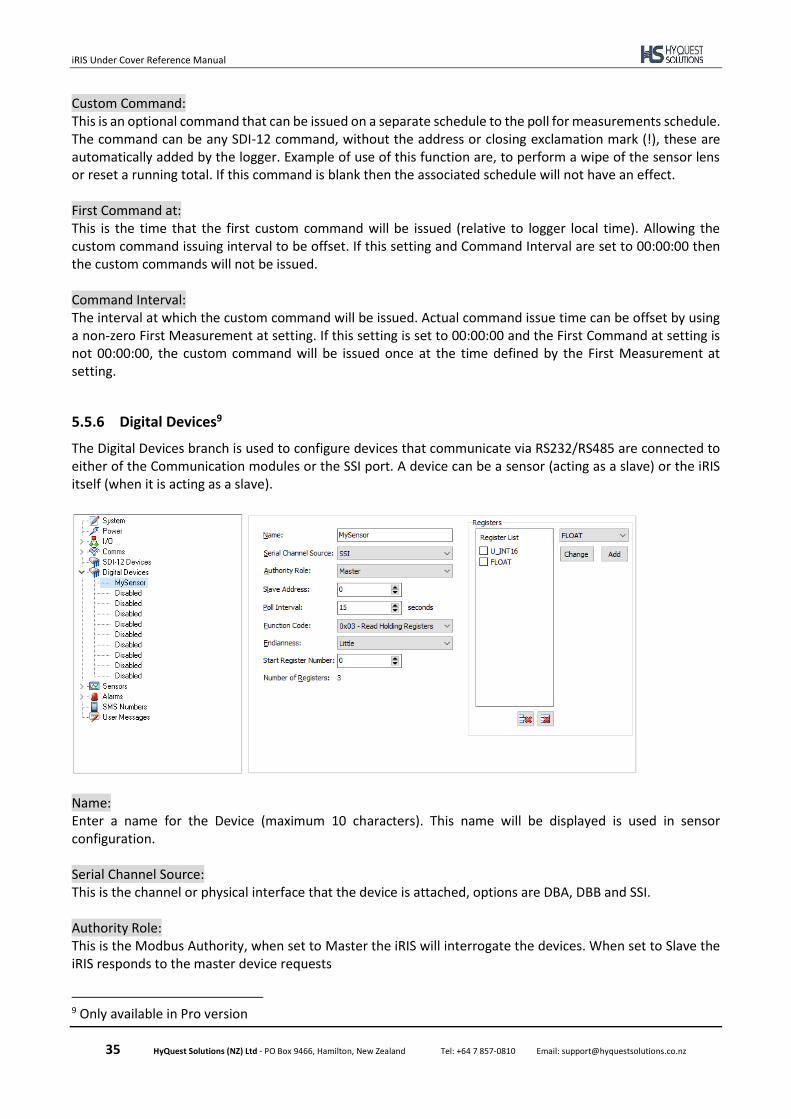
The Digital Devices branch is used to configure devices that communicate via RS232/RS485 are connected to either of the Communication modules or the SSI port. A device can be a sensor (acting as a slave) or the iRIS itself (when it is acting as a slave).
Name: Enter a name for the Device (maximum 10 characters). This name will be displayed is used in sensor configuration. Serial Channel Source: This is the channel or physical interface that the device is attached, options are DBA, DBB and SSI. Authority Role: This is the Modbus Authority, when set to Master the iRIS will interrogate the devices. When set to Slave the iRIS responds to the master device requests
9 Only available in Pro version
iRIS Under Cover Reference Manual
36 HyQuest Solutions (NZ) Ltd - PO Box 9466, Hamilton, New Zealand Tel: +64 7 857-0810 Email: [email protected]
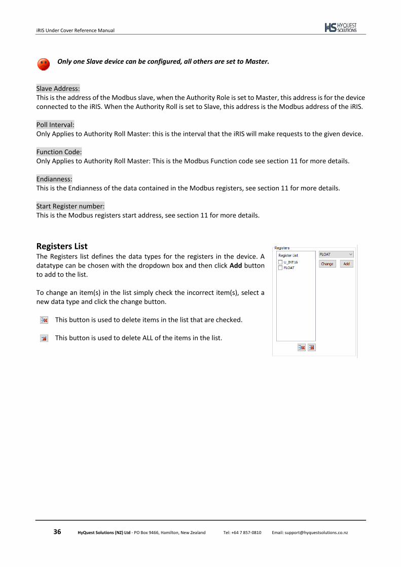
Only one Slave device can be configured, all others are set to Master.
Slave Address: This is the address of the Modbus slave, when the Authority Role is set to Master, this address is for the device connected to the iRIS. When the Authority Roll is set to Slave, this address is the Modbus address of the iRIS. Poll Interval: Only Applies to Authority Roll Master: this is the interval that the iRIS will make requests to the given device. Function Code: Only Applies to Authority Roll Master: This is the Modbus Function code see section 11 for more details. Endianness: This is the Endianness of the data contained in the Modbus registers, see section 11 for more details. Start Register number: This is the Modbus registers start address, see section 11 for more details.
Registers List The Registers list defines the data types for the registers in the device. A datatype can be chosen with the dropdown box and then click Add button to add to the list. To change an item(s) in the list simply check the incorrect item(s), select a new data type and click the change button.
This button is used to delete items in the list that are checked. This button is used to delete ALL of the items in the list.
iRIS Under Cover Reference Manual
37 HyQuest Solutions (NZ) Ltd - PO Box 9466, Hamilton, New Zealand Tel: +64 7 857-0810 Email: [email protected]
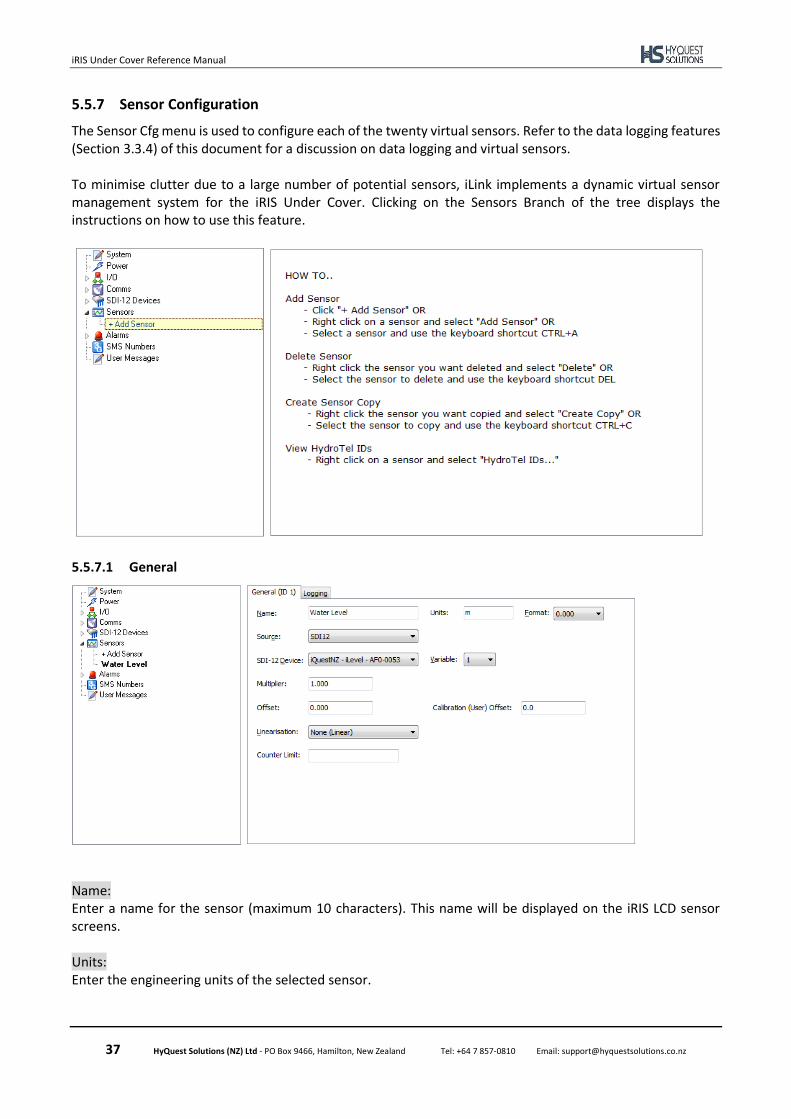
5.5.7 Sensor Configuration
The Sensor Cfg menu is used to configure each of the twenty virtual sensors. Refer to the data logging features (Section 3.3.4) of this document for a discussion on data logging and virtual sensors. To minimise clutter due to a large number of potential sensors, iLink implements a dynamic virtual sensor management system for the iRIS Under Cover. Clicking on the Sensors Branch of the tree displays the instructions on how to use this feature.
5.5.7.1 General
Name: Enter a name for the sensor (maximum 10 characters). This name will be displayed on the iRIS LCD sensor screens. Units: Enter the engineering units of the selected sensor.

iRIS Under Cover Reference Manual
38 HyQuest Solutions (NZ) Ltd - PO Box 9466, Hamilton, New Zealand Tel: +64 7 857-0810 Email: [email protected]
Format: This is the display format to use for the selected sensor. This is used on the LCD screen of the logger to display the sensor readings. Please note if the number to be displayed has more most significant figures than the format configuration allows for then the text on the LCD will be inverted and truncated. For example, when the format is configured as 0.000 and the value to be displayed is 12.2, the value displayed on the LCD will be 2.200 . Source: Choose the source from which the virtual sensor should acquire its data. Use option 0 to disable the sensor. Valid data sources are shown in the table below.
Description Raw Range
Unused / disabled N/A
Supply Voltage
Battery Voltage (External)
Battery Voltage (Internal)
Supply Current
Battery Current (External)
Analogue Input 1 Configurable10
Analogue Input 2 Configurable10
Internal Temperature
Change of State on DI1 0 to 1
Change of State on DI2 0 to 1
Change of State on DIO 0 to 1
Pulse Counter on Digital Input 1 0 to 1
Pulse Counter on Digital Input 2 0 to 1
Pulse Counter on Digital Input 3 0 to 1
Auto Pulse Counter on Digital Input 1 0 to 1
Auto Pulse Counter on Digital Input 2 0 to 1
Auto Pulse Counter on Digital Input 3 0 to 1
Frequency Counter on Digital In 1 0 to 400Hz
Frequency Counter on Digital In 2 0 to 400Hz
Frequency Counter on Digital In 3 0 to 400Hz
Change of State on DI1 0 to 1
Change of State on DI2 0 to 1
Change of State on DIO 0 to 1
Day to Now on Digital Input 1
Day to Now on Digital Input 2
Day to Now on Digital Input 3
Day to Now on Digital Input 4
Year to Date on Digital Input 1
Year to Date on Digital Input 2
Year to Date on Digital Input 3
Year to Date on Digital Input 4
Running Total on Digital Input 1
Running Total on Digital Input 2
10 Range can be configured by user, see section 5.5.3.1
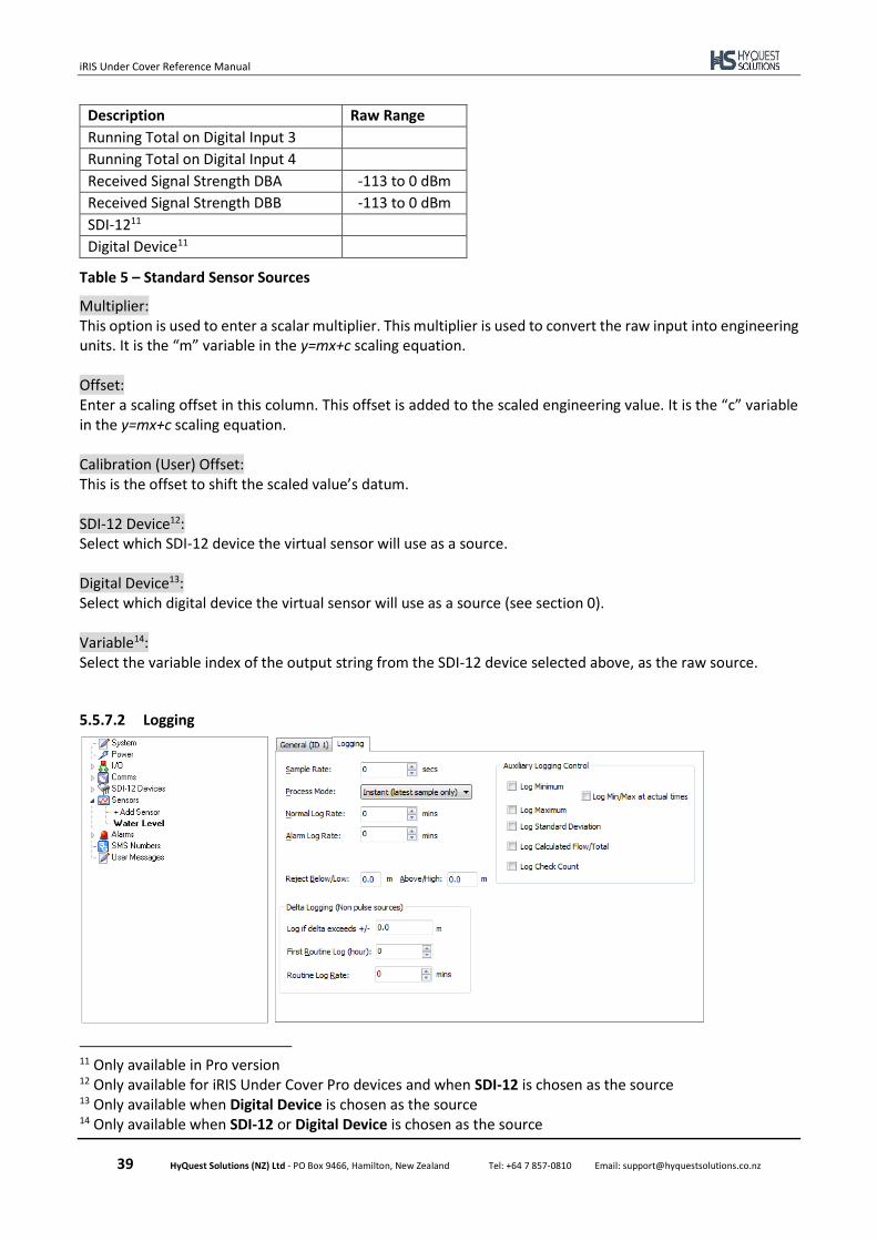
iRIS Under Cover Reference Manual
39 HyQuest Solutions (NZ) Ltd - PO Box 9466, Hamilton, New Zealand Tel: +64 7 857-0810 Email: [email protected]
Description Raw Range
Running Total on Digital Input 3
Running Total on Digital Input 4
Received Signal Strength DBA -113 to 0 dBm
Received Signal Strength DBB -113 to 0 dBm
SDI-1211
Digital Device11
Table 5 – Standard Sensor Sources
Multiplier: This option is used to enter a scalar multiplier. This multiplier is used to convert the raw input into engineering units. It is the “m” variable in the y=mx+c scaling equation. Offset: Enter a scaling offset in this column. This offset is added to the scaled engineering value. It is the “c” variable in the y=mx+c scaling equation. Calibration (User) Offset: This is the offset to shift the scaled value’s datum. SDI-12 Device12: Select which SDI-12 device the virtual sensor will use as a source. Digital Device13: Select which digital device the virtual sensor will use as a source (see section 0). Variable14: Select the variable index of the output string from the SDI-12 device selected above, as the raw source.
5.5.7.2 Logging
11 Only available in Pro version 12 Only available for iRIS Under Cover Pro devices and when SDI-12 is chosen as the source 13 Only available when Digital Device is chosen as the source 14 Only available when SDI-12 or Digital Device is chosen as the source
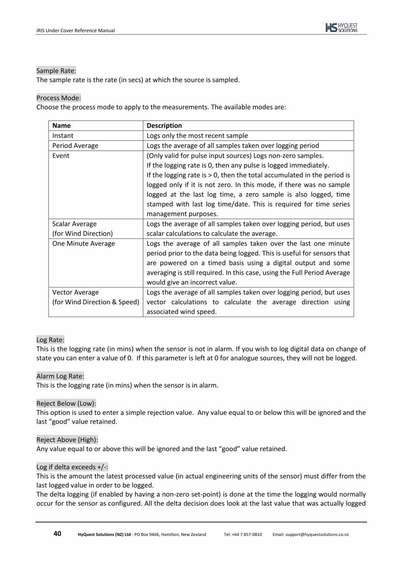
iRIS Under Cover Reference Manual
40 HyQuest Solutions (NZ) Ltd - PO Box 9466, Hamilton, New Zealand Tel: +64 7 857-0810 Email: [email protected]
Sample Rate: The sample rate is the rate (in secs) at which the source is sampled. Process Mode: Choose the process mode to apply to the measurements. The available modes are:
Name Description
Instant Logs only the most recent sample
Period Average Logs the average of all samples taken over logging period
Event (Only valid for pulse input sources) Logs non-zero samples.
If the logging rate is 0, then any pulse is logged immediately.
If the logging rate is > 0, then the total accumulated in the period is
logged only if it is not zero. In this mode, if there was no sample
logged at the last log time, a zero sample is also logged, time
stamped with last log time/date. This is required for time series
management purposes.
Scalar Average
(for Wind Direction)
Logs the average of all samples taken over logging period, but uses
scalar calculations to calculate the average.
One Minute Average Logs the average of all samples taken over the last one minute
period prior to the data being logged. This is useful for sensors that
are powered on a timed basis using a digital output and some
averaging is still required. In this case, using the Full Period Average
would give an incorrect value.
Vector Average
(for Wind Direction & Speed)
Logs the average of all samples taken over logging period, but uses
vector calculations to calculate the average direction using
associated wind speed.
Log Rate: This is the logging rate (in mins) when the sensor is not in alarm. If you wish to log digital data on change of state you can enter a value of 0. If this parameter is left at 0 for analogue sources, they will not be logged. Alarm Log Rate: This is the logging rate (in mins) when the sensor is in alarm. Reject Below (Low): This option is used to enter a simple rejection value. Any value equal to or below this will be ignored and the last “good” value retained. Reject Above (High): Any value equal to or above this will be ignored and the last “good” value retained. Log if delta exceeds +/-: This is the amount the latest processed value (in actual engineering units of the sensor) must differ from the last logged value in order to be logged. The delta logging (if enabled by having a non-zero set-point) is done at the time the logging would normally occur for the sensor as configured. All the delta decision does look at the last value that was actually logged

iRIS Under Cover Reference Manual
41 HyQuest Solutions (NZ) Ltd - PO Box 9466, Hamilton, New Zealand Tel: +64 7 857-0810 Email: [email protected]
and compare it to the newly processed sample value. If the difference is greater than the configured delta value, then the sample is actually logged. First Routine Log (hour): This is the hour in the day when the first routine log will occur. Routine Log Rate: The routine log rate is the interval at which a routine log is taken after the first hour is reached. Auxiliary Logging Control: You can also configure the extended datalogging options using the logging flags. The list of the available flags is given below.
1. Log Minimum value sampled in the log period.
2. Log Maximum value sampled in the log period.
3. Log Standard Deviation of samples in log period.
4. Log Calculated Flow Rate (in l/s) over log period or Log Accumulated Volume for sensors with an
analogue or frequency source.
5. Log Check Count. This optionally logs the background incrementing counter.
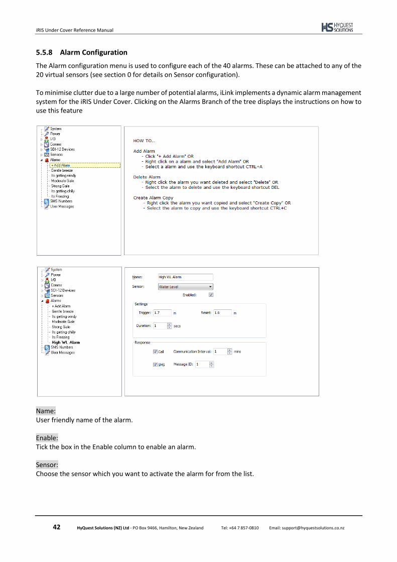
iRIS Under Cover Reference Manual
42 HyQuest Solutions (NZ) Ltd - PO Box 9466, Hamilton, New Zealand Tel: +64 7 857-0810 Email: [email protected]
5.5.8 Alarm Configuration
The Alarm configuration menu is used to configure each of the 40 alarms. These can be attached to any of the 20 virtual sensors (see section 0 for details on Sensor configuration). To minimise clutter due to a large number of potential alarms, iLink implements a dynamic alarm management system for the iRIS Under Cover. Clicking on the Alarms Branch of the tree displays the instructions on how to use this feature
Name: User friendly name of the alarm. Enable: Tick the box in the Enable column to enable an alarm. Sensor: Choose the sensor which you want to activate the alarm for from the list.
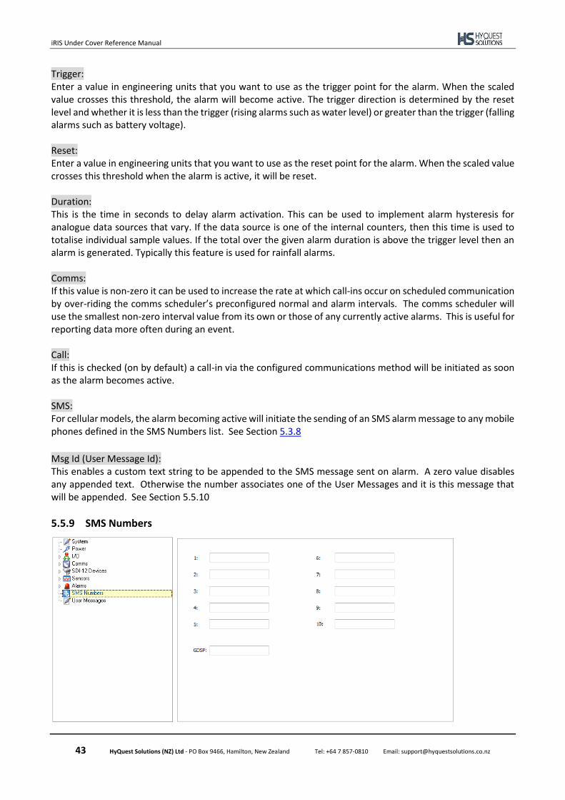
iRIS Under Cover Reference Manual
43 HyQuest Solutions (NZ) Ltd - PO Box 9466, Hamilton, New Zealand Tel: +64 7 857-0810 Email: [email protected]
Trigger: Enter a value in engineering units that you want to use as the trigger point for the alarm. When the scaled value crosses this threshold, the alarm will become active. The trigger direction is determined by the reset level and whether it is less than the trigger (rising alarms such as water level) or greater than the trigger (falling alarms such as battery voltage). Reset: Enter a value in engineering units that you want to use as the reset point for the alarm. When the scaled value crosses this threshold when the alarm is active, it will be reset. Duration: This is the time in seconds to delay alarm activation. This can be used to implement alarm hysteresis for analogue data sources that vary. If the data source is one of the internal counters, then this time is used to totalise individual sample values. If the total over the given alarm duration is above the trigger level then an alarm is generated. Typically this feature is used for rainfall alarms. Comms: If this value is non-zero it can be used to increase the rate at which call-ins occur on scheduled communication by over-riding the comms scheduler’s preconfigured normal and alarm intervals. The comms scheduler will use the smallest non-zero interval value from its own or those of any currently active alarms. This is useful for reporting data more often during an event. Call: If this is checked (on by default) a call-in via the configured communications method will be initiated as soon as the alarm becomes active. SMS: For cellular models, the alarm becoming active will initiate the sending of an SMS alarm message to any mobile phones defined in the SMS Numbers list. See Section 5.3.8
Msg Id (User Message Id): This enables a custom text string to be appended to the SMS message sent on alarm. A zero value disables any appended text. Otherwise the number associates one of the User Messages and it is this message that will be appended. See Section 5.5.10
5.5.9 SMS Numbers
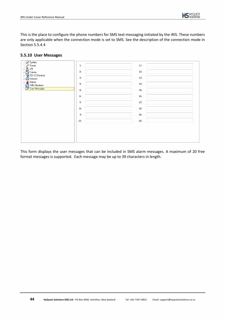
iRIS Under Cover Reference Manual
44 HyQuest Solutions (NZ) Ltd - PO Box 9466, Hamilton, New Zealand Tel: +64 7 857-0810 Email: [email protected]
This is the place to configure the phone numbers for SMS text messaging initiated by the iRIS. These numbers are only applicable when the connection mode is set to SMS. See the description of the connection mode in Section 5.5.4.4
5.5.10 User Messages
This form displays the user messages that can be included in SMS alarm messages. A maximum of 20 free format messages is supported. Each message may be up to 39 characters in length.
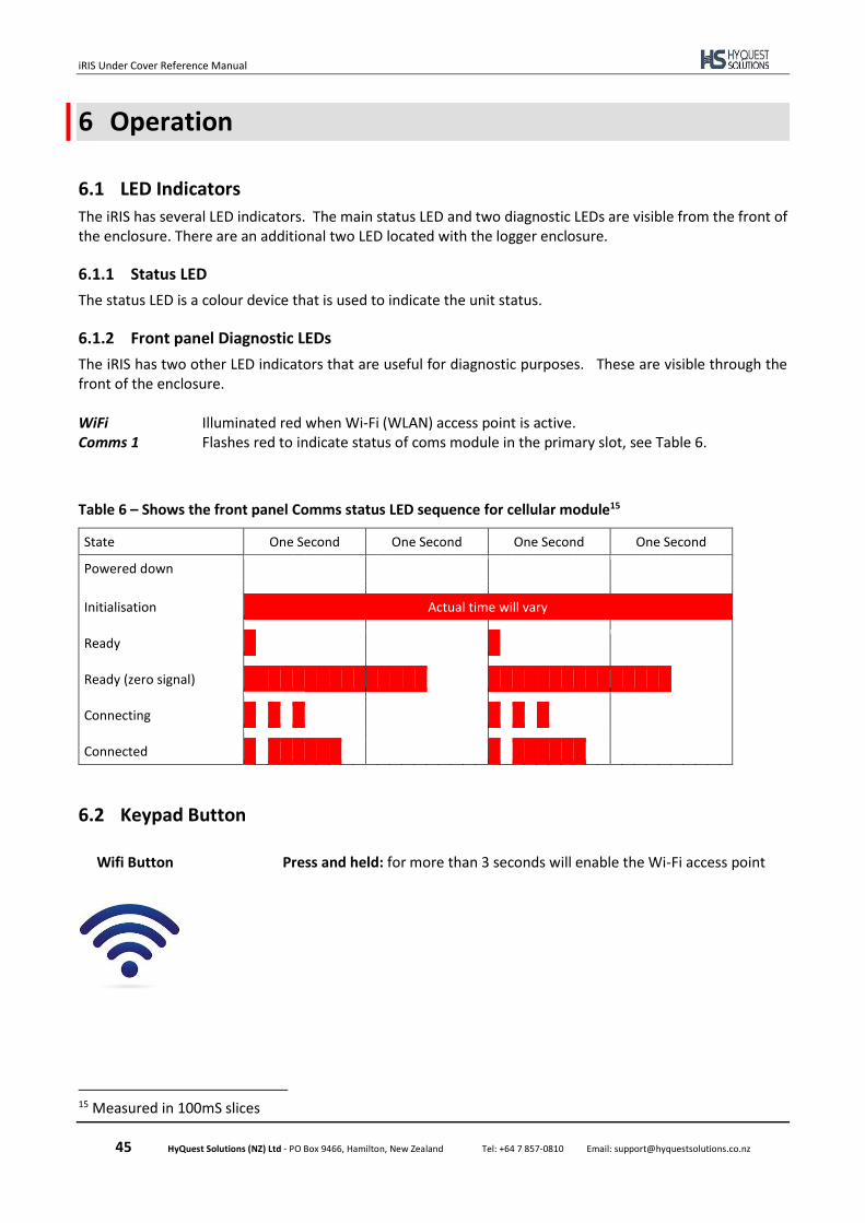
iRIS Under Cover Reference Manual
45 HyQuest Solutions (NZ) Ltd - PO Box 9466, Hamilton, New Zealand Tel: +64 7 857-0810 Email: [email protected]
6 Operation
6.1 LED Indicators
The iRIS has several LED indicators. The main status LED and two diagnostic LEDs are visible from the front of the enclosure. There are an additional two LED located with the logger enclosure.
6.1.1 Status LED
The status LED is a colour device that is used to indicate the unit status.
6.1.2 Front panel Diagnostic LEDs
The iRIS has two other LED indicators that are useful for diagnostic purposes. These are visible through the front of the enclosure. WiFi Illuminated red when Wi-Fi (WLAN) access point is active. Comms 1 Flashes red to indicate status of coms module in the primary slot, see Table 6.
Table 6 – Shows the front panel Comms status LED sequence for cellular module15
State One Second One Second One Second One Second
Powered down
Initialisation Actual time will vary
Ready
Ready (zero signal)
Connecting
Connected
6.2 Keypad Button
Wifi Button Press and held: for more than 3 seconds will enable the Wi-Fi access point
15 Measured in 100mS slices
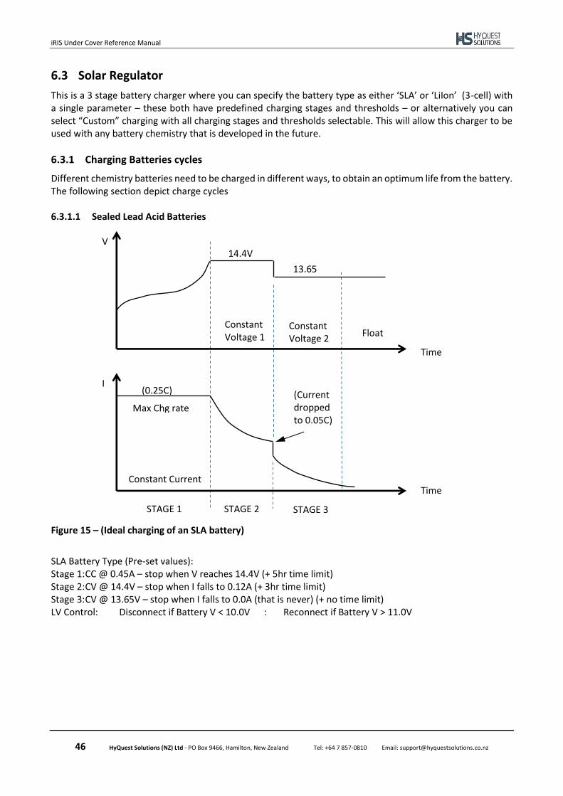
iRIS Under Cover Reference Manual
46 HyQuest Solutions (NZ) Ltd - PO Box 9466, Hamilton, New Zealand Tel: +64 7 857-0810 Email: [email protected]
6.3 Solar Regulator
This is a 3 stage battery charger where you can specify the battery type as either ‘SLA’ or ‘LiIon’ (3-cell) with a single parameter – these both have predefined charging stages and thresholds – or alternatively you can select “Custom” charging with all charging stages and thresholds selectable. This will allow this charger to be used with any battery chemistry that is developed in the future.
6.3.1 Charging Batteries cycles
Different chemistry batteries need to be charged in different ways, to obtain an optimum life from the battery. The following section depict charge cycles 6.3.1.1 Sealed Lead Acid Batteries
Figure 15 – (Ideal charging of an SLA battery)
SLA Battery Type (Pre-set values): Stage 1: CC @ 0.45A – stop when V reaches 14.4V (+ 5hr time limit) Stage 2: CV @ 14.4V – stop when I falls to 0.12A (+ 3hr time limit) Stage 3: CV @ 13.65V – stop when I falls to 0.0A (that is never) (+ no time limit) LV Control: Disconnect if Battery V < 10.0V : Reconnect if Battery V > 11.0V
V
Time
13.65V
14.4V
Constant Voltage 1
Constant Voltage 2
Float
I
Time Constant Current
(0.25C) (Current dropped to 0.05C)
Max Chg rate
STAGE 1 STAGE 2 STAGE 3
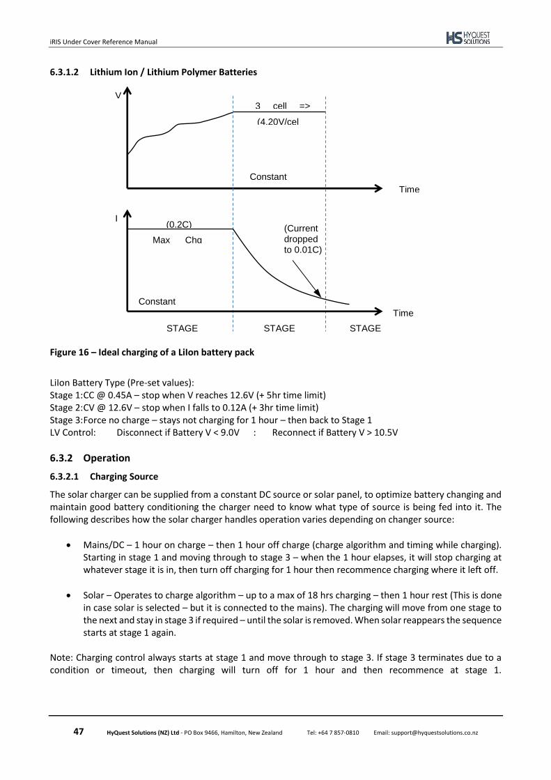
iRIS Under Cover Reference Manual
47 HyQuest Solutions (NZ) Ltd - PO Box 9466, Hamilton, New Zealand Tel: +64 7 857-0810 Email: [email protected]
6.3.1.2 Lithium Ion / Lithium Polymer Batteries
Figure 16 – Ideal charging of a LiIon battery pack
LiIon Battery Type (Pre-set values): Stage 1: CC @ 0.45A – stop when V reaches 12.6V (+ 5hr time limit) Stage 2: CV @ 12.6V – stop when I falls to 0.12A (+ 3hr time limit) Stage 3: Force no charge – stays not charging for 1 hour – then back to Stage 1 LV Control: Disconnect if Battery V < 9.0V : Reconnect if Battery V > 10.5V
6.3.2 Operation
6.3.2.1 Charging Source
The solar charger can be supplied from a constant DC source or solar panel, to optimize battery changing and maintain good battery conditioning the charger need to know what type of source is being fed into it. The following describes how the solar charger handles operation varies depending on changer source:
• Mains/DC – 1 hour on charge – then 1 hour off charge (charge algorithm and timing while charging). Starting in stage 1 and moving through to stage 3 – when the 1 hour elapses, it will stop charging at whatever stage it is in, then turn off charging for 1 hour then recommence charging where it left off.
• Solar – Operates to charge algorithm – up to a max of 18 hrs charging – then 1 hour rest (This is done in case solar is selected – but it is connected to the mains). The charging will move from one stage to the next and stay in stage 3 if required – until the solar is removed. When solar reappears the sequence starts at stage 1 again.
Note: Charging control always starts at stage 1 and move through to stage 3. If stage 3 terminates due to a condition or timeout, then charging will turn off for 1 hour and then recommence at stage 1.
V
Time
(4.20V/cell)
3 cell => 12.6V
Constant Voltage
I
Time Constant Current
(0.2C) (Current dropped to 0.01C)
Max Chg rate
STAGE 1
STAGE 1
STAGE 1
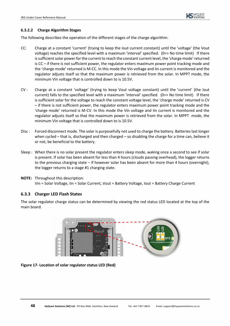
iRIS Under Cover Reference Manual
48 HyQuest Solutions (NZ) Ltd - PO Box 9466, Hamilton, New Zealand Tel: +64 7 857-0810 Email: [email protected]
6.3.2.2 Charge Algorithm Stages
The following describes the operation of the different stages of the charge algorithm: CC: Charge at a constant ‘current’ (trying to keep the Iout current constant) until the ’voltage’ (the Vout
voltage) reaches the specified level with a maximum ‘interval’ specified. (0=> No time limit) If there is sufficient solar power for the current to reach the constant current level, the ‘charge mode’ returned is CC – if there is not sufficient power, the regulator enters maximum power point tracking mode and the ‘charge mode’ returned is M-CC. In this mode the Vin voltage and Iin current is monitored and the regulator adjusts itself so that the maximum power is retrieved from the solar. In MPPT mode, the minimum Vin voltage that is controlled down to is 10.5V.
CV : Charge at a constant ‘voltage’ (trying to keep Vout voltage constant) until the ’current’ (the Iout
current) falls to the specified level with a maximum ‘interval’ specified. (0=> No time limit) If there is sufficient solar for the voltage to reach the constant voltage level, the ‘charge mode’ returned is CV – if there is not sufficient power, the regulator enters maximum power point tracking mode and the ‘charge mode’ returned is M-CV. In this mode the Vin voltage and Iin current is monitored and the regulator adjusts itself so that the maximum power is retrieved from the solar. In MPPT mode, the minimum Vin voltage that is controlled down to is 10.5V.
Disc : Forced disconnect mode. The solar is purposefully not used to charge the battery. Batteries last longer
when cycled – that is, discharged and then charged – so disabling the charge for a time can, believe it or not, be beneficial to the battery.
Sleep : When there is no solar present the regulator enters sleep mode, waking once a second to see if solar
is present. If solar has been absent for less than 4 hours (clouds passing overhead), the logger returns to the previous charging state – if however solar has been absent for more than 4 hours (overnight), the logger returns to a stage #1 charging state.
NOTE: Throughout this description:
Vin = Solar Voltage, Iin = Solar Current, Vout = Battery Voltage, Iout = Battery Charge Current
6.3.3 Charger LED Flash States
The solar regulator charge status can be determined by viewing the red status LED located at the top of the main board.
Figure 17- Location of solar regulator status LED (Red)
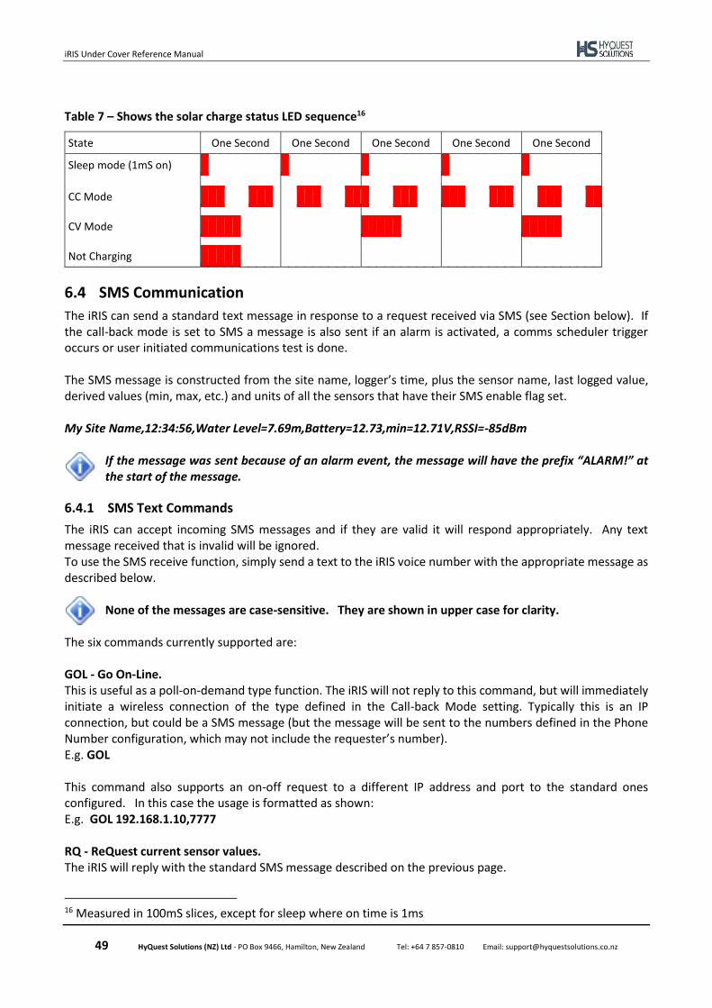
iRIS Under Cover Reference Manual
49 HyQuest Solutions (NZ) Ltd - PO Box 9466, Hamilton, New Zealand Tel: +64 7 857-0810 Email: [email protected]
Table 7 – Shows the solar charge status LED sequence16
State One Second One Second One Second One Second One Second
Sleep mode (1mS on)
CC Mode
CV Mode
Not Charging
6.4 SMS Communication
The iRIS can send a standard text message in response to a request received via SMS (see Section below). If the call-back mode is set to SMS a message is also sent if an alarm is activated, a comms scheduler trigger occurs or user initiated communications test is done. The SMS message is constructed from the site name, logger’s time, plus the sensor name, last logged value, derived values (min, max, etc.) and units of all the sensors that have their SMS enable flag set. My Site Name,12:34:56,Water Level=7.69m,Battery=12.73,min=12.71V,RSSI=-85dBm
If the message was sent because of an alarm event, the message will have the prefix “ALARM!” at the start of the message.
6.4.1 SMS Text Commands
The iRIS can accept incoming SMS messages and if they are valid it will respond appropriately. Any text message received that is invalid will be ignored. To use the SMS receive function, simply send a text to the iRIS voice number with the appropriate message as described below.
None of the messages are case-sensitive. They are shown in upper case for clarity.
The six commands currently supported are: GOL - Go On-Line. This is useful as a poll-on-demand type function. The iRIS will not reply to this command, but will immediately initiate a wireless connection of the type defined in the Call-back Mode setting. Typically this is an IP connection, but could be a SMS message (but the message will be sent to the numbers defined in the Phone Number configuration, which may not include the requester’s number). E.g. GOL This command also supports an on-off request to a different IP address and port to the standard ones configured. In this case the usage is formatted as shown: E.g. GOL 192.168.1.10,7777 RQ - ReQuest current sensor values. The iRIS will reply with the standard SMS message described on the previous page.
16 Measured in 100mS slices, except for sleep where on time is 1ms
iRIS Under Cover Reference Manual
50 HyQuest Solutions (NZ) Ltd - PO Box 9466, Hamilton, New Zealand Tel: +64 7 857-0810 Email: [email protected]
WiFi – Change the state of the Wi-Fi access point in the logger. This command can be used to turn on or off the Wi-Fi access point via SMS message, the same action as pressing and holding the centre button (see section 5.1 or 5.2). This can be of use if the keypad of the logger is not easily accessible. To turn on the Wi-Fi send the message:
WiFi on
To turn off the Wi-Fi send the message:
WiFi off
6.5 File Transfer Protocol (FTP) Operation
The iRIS acts as an FTP client, when requested to connect to a given FTP server it will upload a file containing data since the last upload. The iRIS can communicate with up to two servers at the same time, each has an associated independent start of data pointer, which means only new data is uploaded not all data since beginning of memory. The data format and file name convention are described in the following sections.
6.5.1 File Name Convention
The file name is made up of a five elements and inclusion/exclusion of the elements is user configurable via a set of check boxes (see 0). The possible elements are as follows:
• Base File Name – this is a constant alphanumeric of up to 16 characters. Avoid using reserved characters such as \ /:*?”<>?|
• Serial Number – the serial number of the logger in the format AG5-XXXX where XXXX is a number between 0000 and 9999.
• Site Name – the site name as configured in section 5.5.1.
• Date Time – the date and time of the transaction. The order of the day month and year is defined by the Date format in the system configuration (see section 5.5.1) and the application of the UTC offset (configured in section 5.5.1) is defined by the Sample Time Stamps in UTC option in section 0
• File Type – this defines the extension either .CSV or .TXT The order of the elements is fixed and are separated by underscores (except the extension which is separated by a period), as follows:
<BaseFileName>_<SerialNumber>_<SiteName>_<DateTime>.Extention
The following are some examples of possible file name.
MyFile_AG5-0002_InnovationPark_240918204526.csv
AG5-0002_240918204526.csv
240918204526.txt
MyFile.csv
AG5-0002.csv
iRIS Under Cover Reference Manual
51 HyQuest Solutions (NZ) Ltd - PO Box 9466, Hamilton, New Zealand Tel: +64 7 857-0810 Email: [email protected]
6.5.2 File Contents Format
The file contents format for both CSV and TXT types is the same and can be considered as Comma Separated Values format (CSV). An optional header, which describes the columns can be placed on the first line/row of the file. The insertion is controlled by the Include Header option, see section 0. The header is as follows:
Sensor ID,Sample Date,Sample Time,Sample Value<CR><LF>
The remainder of the file contains one or more lines, each with four elements:
• Sensor ID – this is the Virtual Sensor number (1-20) as configured in section 0.
• Sample Date – this is the date of when the sample is recorded, the format is configured in section 5.5.1.
• Sample Time – this is the time of when the sample is recoded. The application of UTC offset (configured in section 5.5.1) to this value is defined by the Sample Time Stamps in UTC option which can be configured in 0.
• Sample Value – the value measured by the logger at the sample date and time for the given sensor ID. The value has a fixed-point format and this can be configured on a per sensor basis and is configured by the Format setting (see section 5.5.7.1).
An example of the file data is (without header):
1,23/09/2018,21:10:00,1.290000<CR><LF>
1,23/09/2018,21:10:00,1.310000<CR><LF>
1,23/09/2018,21:15:00,1.300000<CR><LF>
2,23/09/2018,21:10:00,25.125000<CR><LF>
2,23/09/2018,21:10:00,25.250000<CR><LF>
2,23/09/2018,21:15:00,25.125000<CR><LF>
3,23/09/2018,21:10:00,12.330000<CR><LF>
3,23/09/2018,21:10:00,12.350000<CR><LF>
3,23/09/2018,21:15:00,12.337626<CR><LF>
Note all lines are terminated with a carriage return and linefeed.
6.6 General Hints
If the unit is not to be used for some time, disconnect the internal battery to prevent it discharging. Always check the time and date are correct when commissioning the unit. The internal clock runs in UTC
(GMT) and all logged data is time/date stamped in this time zone. HydroTel™ and/or iLink 2012 automatically adjust for this.
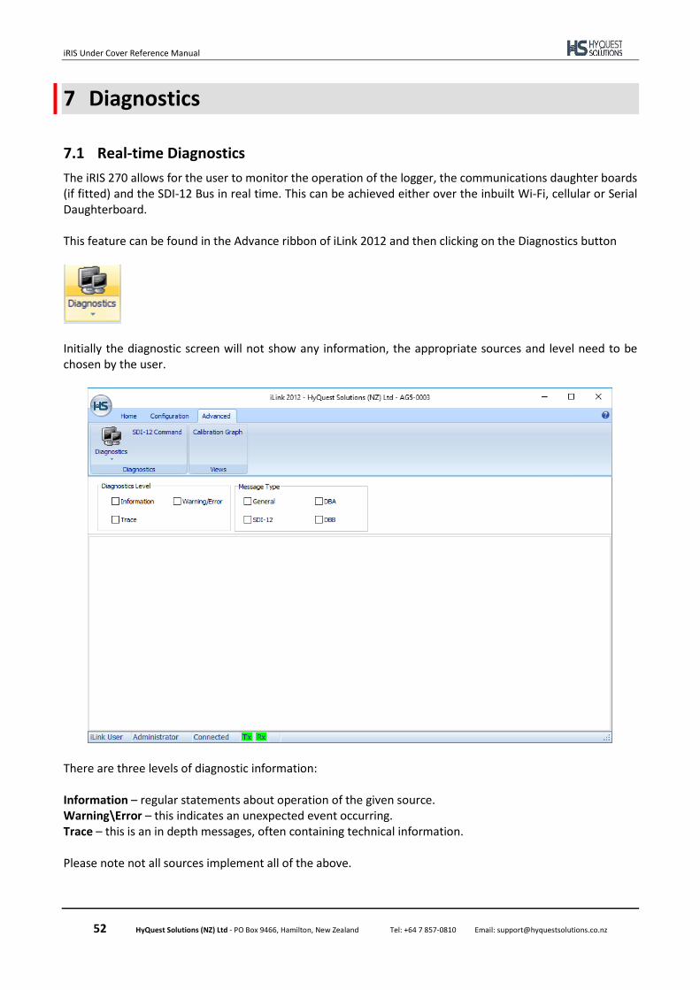
iRIS Under Cover Reference Manual
52 HyQuest Solutions (NZ) Ltd - PO Box 9466, Hamilton, New Zealand Tel: +64 7 857-0810 Email: [email protected]
7 Diagnostics
7.1 Real-time Diagnostics
The iRIS 270 allows for the user to monitor the operation of the logger, the communications daughter boards (if fitted) and the SDI-12 Bus in real time. This can be achieved either over the inbuilt Wi-Fi, cellular or Serial Daughterboard. This feature can be found in the Advance ribbon of iLink 2012 and then clicking on the Diagnostics button
Initially the diagnostic screen will not show any information, the appropriate sources and level need to be chosen by the user.
There are three levels of diagnostic information: Information – regular statements about operation of the given source. Warning\Error – this indicates an unexpected event occurring. Trace – this is an in depth messages, often containing technical information. Please note not all sources implement all of the above.

iRIS Under Cover Reference Manual
53 HyQuest Solutions (NZ) Ltd - PO Box 9466, Hamilton, New Zealand Tel: +64 7 857-0810 Email: [email protected]
There are four message sources (or Message Types): General – this relates to general operation of the logger, for example digital output schedules. DBA – messages relating to the operation of the first daughter board. DBB – messages relating to the second daughter board. SDI-12 – messages relating to the activity on the SDI-12 Bus. The following is an example of the power on sequence of the daughter board A and without a SIM card fitted:
The grid can be cleared by right clicking and selecting Clear Grid:
Diagnostics information and be saved by clicking the small arrow below the Diagnostics button in the advance ribbon.
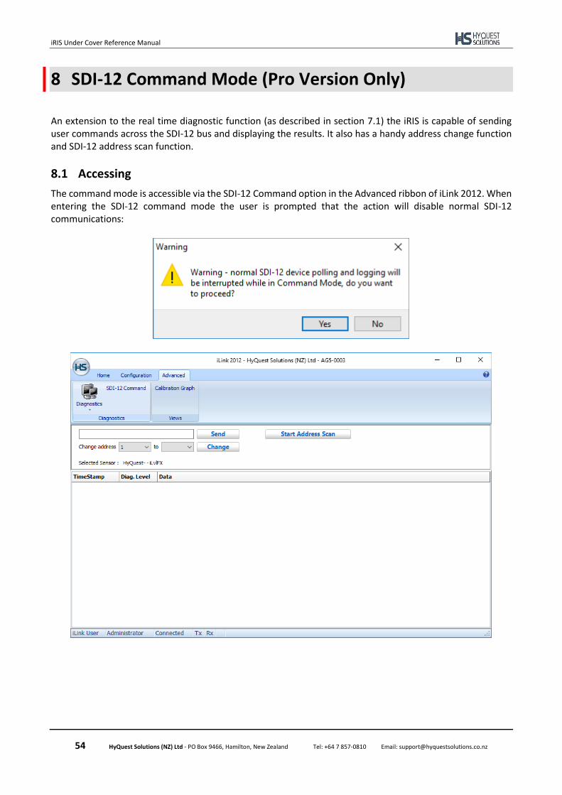
iRIS Under Cover Reference Manual
54 HyQuest Solutions (NZ) Ltd - PO Box 9466, Hamilton, New Zealand Tel: +64 7 857-0810 Email: [email protected]
8 SDI-12 Command Mode (Pro Version Only)
An extension to the real time diagnostic function (as described in section 7.1) the iRIS is capable of sending user commands across the SDI-12 bus and displaying the results. It also has a handy address change function and SDI-12 address scan function.
8.1 Accessing
The command mode is accessible via the SDI-12 Command option in the Advanced ribbon of iLink 2012. When entering the SDI-12 command mode the user is prompted that the action will disable normal SDI-12 communications:
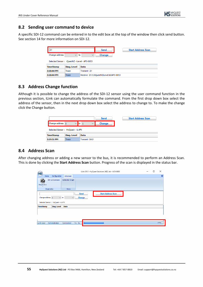
iRIS Under Cover Reference Manual
55 HyQuest Solutions (NZ) Ltd - PO Box 9466, Hamilton, New Zealand Tel: +64 7 857-0810 Email: [email protected]
8.2 Sending user command to device
A specific SDI-12 command can be entered in to the edit box at the top of the window then click send button. See section 14 for more information on SDI-12.
8.3 Address Change function
Although it is possible to change the address of the SDI-12 sensor using the user command function in the previous section, iLink can automatically formulate the command. From the first drop down box select the address of the sensor, then in the next drop down box select the address to change to. To make the change click the Change button.
8.4 Address Scan
After changing address or adding a new sensor to the bus, it is recommended to perform an Address Scan. This is done by clicking the Start Address Scan button. Progress of the scan is displayed in the status bar.
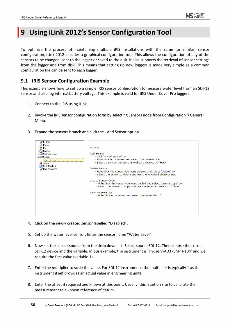
iRIS Under Cover Reference Manual
56 HyQuest Solutions (NZ) Ltd - PO Box 9466, Hamilton, New Zealand Tel: +64 7 857-0810 Email: [email protected]
9 Using iLink 2012’s Sensor Configuration Tool
To optimize the process of maintaining multiple iRIS installations with the same (or similar) sensor configuration, iLink 2012 includes a graphical configuration tool. This allows the configuration of any of the sensors to be changed, sent to the logger or saved to the disk. It also supports the retrieval of sensor settings from the logger and from disk. This means that setting up new loggers is made very simple as a common configuration file can be sent to each logger.
9.1 iRIS Sensor Configuration Example
This example shows how to set up a simple iRIS sensor configuration to measure water level from an SDI-12 sensor and also log internal battery voltage. This example is valid for iRIS Under Cover Pro loggers.
1. Connect to the iRIS using iLink.
2. Invoke the iRIS sensor configuration form by selecting Sensors node from Configuration→General
Menu.
3. Expand the sensors branch and click the +Add Sensor option.
4. Click on the newly created sensor labelled “Disabled”.
5. Set up the water level sensor. Enter the sensor name “Water Level”.
6. Now set the sensor source from the drop down list. Select source SDI-12. Then choose the correct
SDI-12 device and the variable. In our example, the instrument is ‘Hydserv-AD375M-H-104’ and we
require the first value (variable 1).
7. Enter the multiplier to scale the value. For SDI-12 instruments, the multiplier is typically 1 as the
instrument itself provides an actual value in engineering units.
8. Enter the offset if required and known at this point. Usually, this is set on site to calibrate the
measurement to a known reference of datum.
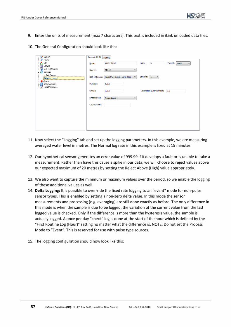
iRIS Under Cover Reference Manual
57 HyQuest Solutions (NZ) Ltd - PO Box 9466, Hamilton, New Zealand Tel: +64 7 857-0810 Email: [email protected]
9. Enter the units of measurement (max 7 characters). This text is included in iLink unloaded data files.
10. The General Configuration should look like this:
11. Now select the “Logging” tab and set up the logging parameters. In this example, we are measuring
averaged water level in metres. The Normal log rate in this example is fixed at 15 minutes.
12. Our hypothetical sensor generates an error value of 999.99 if it develops a fault or is unable to take a
measurement. Rather than have this cause a spike in our data, we will choose to reject values above
our expected maximum of 20 metres by setting the Reject Above (High) value appropriately.
13. We also want to capture the minimum or maximum values over the period, so we enable the logging
of these additional values as well.
14. Delta Logging: It is possible to over-ride the fixed rate logging to an “event” mode for non-pulse
sensor types. This is enabled by setting a non-zero delta value. In this mode the sensor
measurements and processing (e.g. averaging) are still done exactly as before. The only difference in
this mode is when the sample is due to be logged, the variation of the current value from the last
logged value is checked. Only if the difference is more than the hysteresis value, the sample is
actually logged. A once per day “check” log is done at the start of the hour which is defined by the
“First Routine Log (Hour)” setting no matter what the difference is. NOTE: Do not set the Process
Mode to “Event”. This is reserved for use with pulse type sources.
15. The logging configuration should now look like this:
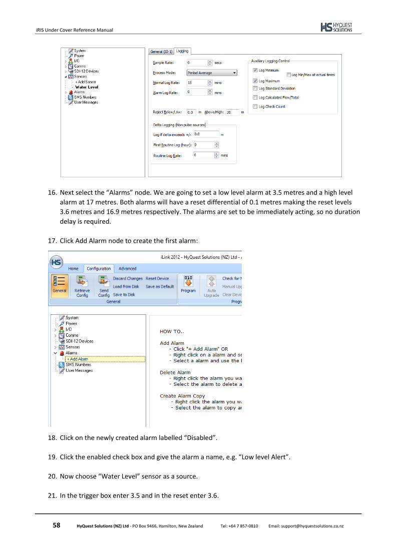
iRIS Under Cover Reference Manual
58 HyQuest Solutions (NZ) Ltd - PO Box 9466, Hamilton, New Zealand Tel: +64 7 857-0810 Email: [email protected]
16. Next select the “Alarms” node. We are going to set a low level alarm at 3.5 metres and a high level
alarm at 17 metres. Both alarms will have a reset differential of 0.1 metres making the reset levels
3.6 metres and 16.9 metres respectively. The alarms are set to be immediately acting, so no duration
delay is required.
17. Click Add Alarm node to create the first alarm:
18. Click on the newly created alarm labelled “Disabled”.
19. Click the enabled check box and give the alarm a name, e.g. “Low level Alert”.
20. Now choose “Water Level” sensor as a source.
21. In the trigger box enter 3.5 and in the reset enter 3.6.
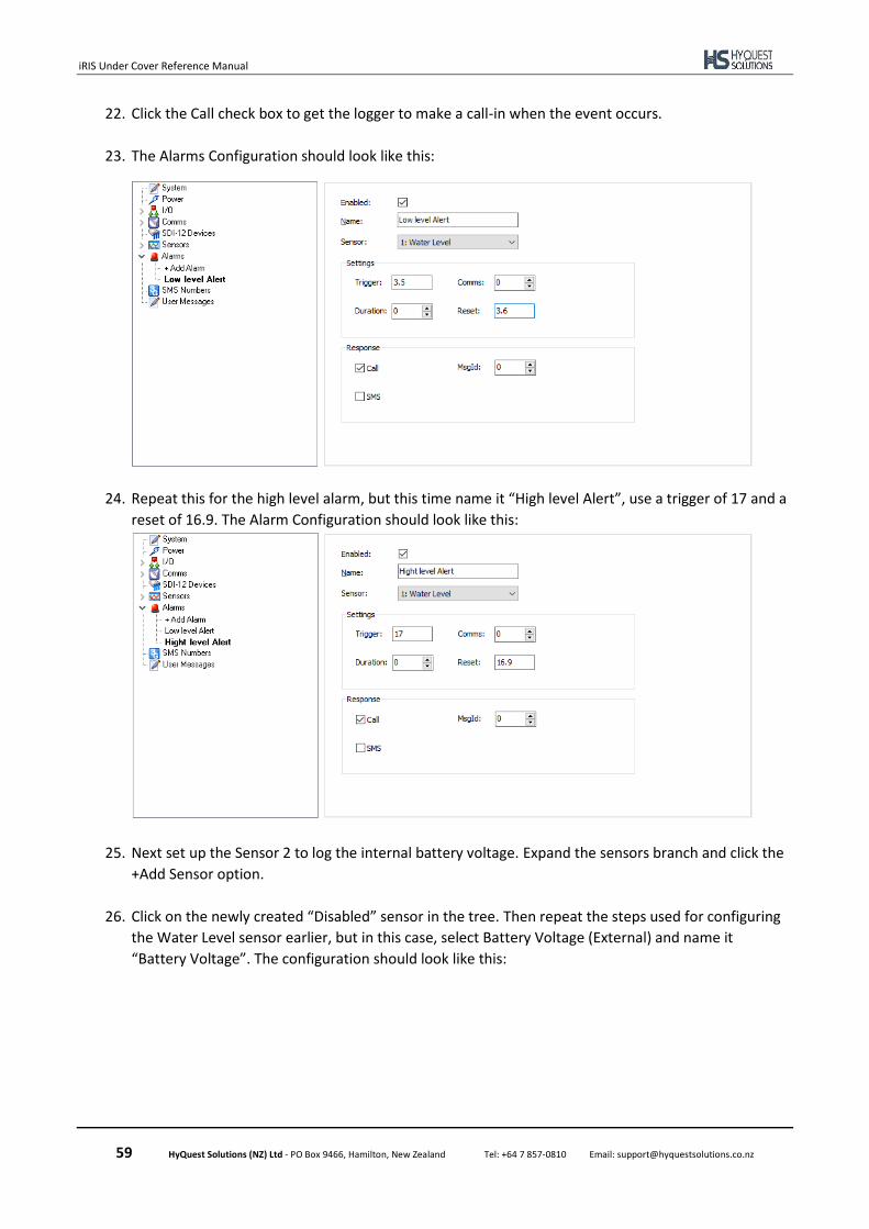
iRIS Under Cover Reference Manual
59 HyQuest Solutions (NZ) Ltd - PO Box 9466, Hamilton, New Zealand Tel: +64 7 857-0810 Email: [email protected]
22. Click the Call check box to get the logger to make a call-in when the event occurs.
23. The Alarms Configuration should look like this:
24. Repeat this for the high level alarm, but this time name it “High level Alert”, use a trigger of 17 and a
reset of 16.9. The Alarm Configuration should look like this:
25. Next set up the Sensor 2 to log the internal battery voltage. Expand the sensors branch and click the
+Add Sensor option.
26. Click on the newly created “Disabled” sensor in the tree. Then repeat the steps used for configuring
the Water Level sensor earlier, but in this case, select Battery Voltage (External) and name it
“Battery Voltage”. The configuration should look like this:
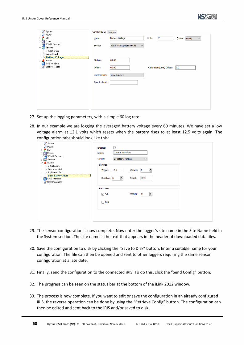
iRIS Under Cover Reference Manual
60 HyQuest Solutions (NZ) Ltd - PO Box 9466, Hamilton, New Zealand Tel: +64 7 857-0810 Email: [email protected]
27. Set up the logging parameters, with a simple 60 log rate.
28. In our example we are logging the averaged battery voltage every 60 minutes. We have set a low
voltage alarm at 12.1 volts which resets when the battery rises to at least 12.5 volts again. The
configuration tabs should look like this:
29. The sensor configuration is now complete. Now enter the logger’s site name in the Site Name field in
the System section. The site name is the text that appears in the header of downloaded data files.
30. Save the configuration to disk by clicking the “Save to Disk” button. Enter a suitable name for your
configuration. The file can then be opened and sent to other loggers requiring the same sensor
configuration at a late date.
31. Finally, send the configuration to the connected iRIS. To do this, click the “Send Config” button.
32. The progress can be seen on the status bar at the bottom of the iLink 2012 window.
33. The process is now complete. If you want to edit or save the configuration in an already configured
iRIS, the reverse operation can be done by using the “Retrieve Config” button. The configuration can
then be edited and sent back to the iRIS and/or saved to disk.
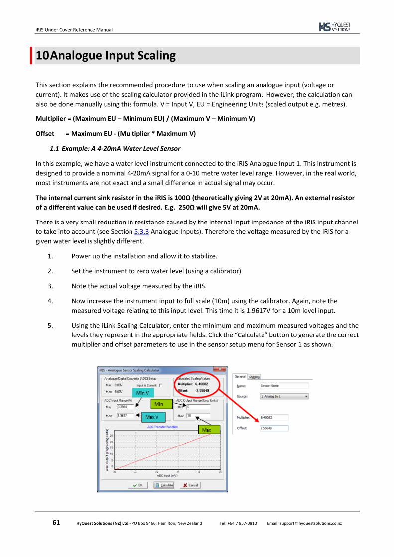
iRIS Under Cover Reference Manual
61 HyQuest Solutions (NZ) Ltd - PO Box 9466, Hamilton, New Zealand Tel: +64 7 857-0810 Email: [email protected]
10 Analogue Input Scaling
This section explains the recommended procedure to use when scaling an analogue input (voltage or
current). It makes use of the scaling calculator provided in the iLink program. However, the calculation can
also be done manually using this formula. V = Input V, EU = Engineering Units (scaled output e.g. metres).
Multiplier = (Maximum EU – Minimum EU) / (Maximum V – Minimum V)
Offset = Maximum EU - (Multiplier * Maximum V)
1.1 Example: A 4-20mA Water Level Sensor
In this example, we have a water level instrument connected to the iRIS Analogue Input 1. This instrument is
designed to provide a nominal 4-20mA signal for a 0-10 metre water level range. However, in the real world,
most instruments are not exact and a small difference in actual signal may occur.
The internal current sink resistor in the iRIS is 100Ω (theoretically giving 2V at 20mA). An external resistor
of a different value can be used if desired. E.g. 250Ω will give 5V at 20mA.
There is a very small reduction in resistance caused by the internal input impedance of the iRIS input channel
to take into account (see Section 5.3.3 Analogue Inputs). Therefore the voltage measured by the iRIS for a
given water level is slightly different.
1. Power up the installation and allow it to stabilize.
2. Set the instrument to zero water level (using a calibrator)
3. Note the actual voltage measured by the iRIS.
4. Now increase the instrument input to full scale (10m) using the calibrator. Again, note the
measured voltage relating to this input level. This time it is 1.9617V for a 10m level input.
5. Using the iLink Scaling Calculator, enter the minimum and maximum measured voltages and the
levels they represent in the appropriate fields. Click the “Calculate” button to generate the correct
multiplier and offset parameters to use in the sensor setup menu for Sensor 1 as shown.
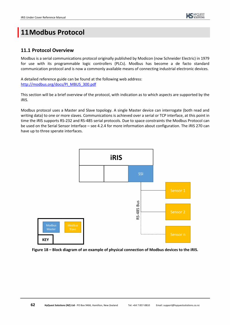
iRIS Under Cover Reference Manual
62 HyQuest Solutions (NZ) Ltd - PO Box 9466, Hamilton, New Zealand Tel: +64 7 857-0810 Email: [email protected]
11 Modbus Protocol
11.1 Protocol Overview
Modbus is a serial communications protocol originally published by Modicon (now Schneider Electric) in 1979 for use with its programmable logic controllers (PLCs). Modbus has become a de facto standard communication protocol and is now a commonly available means of connecting industrial electronic devices. A detailed reference guide can be found at the following web address: http://modbus.org/docs/PI_MBUS_300.pdf This section will be a brief overview of the protocol, with indication as to which aspects are supported by the iRIS. Modbus protocol uses a Master and Slave topology. A single Master device can interrogate (both read and writing data) to one or more slaves. Communications is achieved over a serial or TCP interface, at this point in time the iRIS supports RS-232 and RS-485 serial protocols. Due to space constraints the Modbus Protocol can be used on the Serial Sensor Interface – see 4.2.4 for more information about configuration. The iRIS 270 can have up to three sperate interfaces.
Figure 18 – Block diagram of an example of physical connection of Modbus devices to the iRIS.
iRIS
Serial DBB SSI
Sensor 1
Sensor 2
Sensor n
RS-
485
Bu
s
Modbus Master
Modbus Slave
KEY
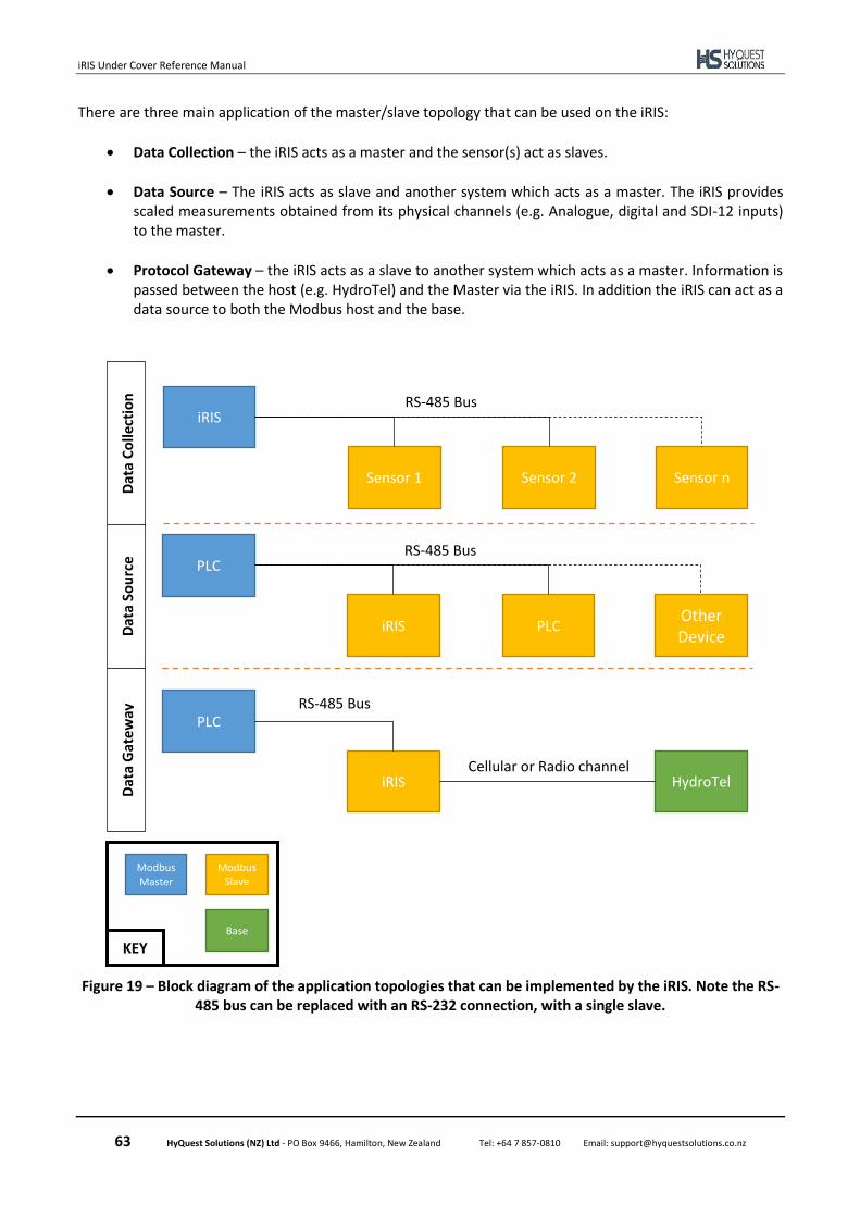
iRIS Under Cover Reference Manual
63 HyQuest Solutions (NZ) Ltd - PO Box 9466, Hamilton, New Zealand Tel: +64 7 857-0810 Email: [email protected]
There are three main application of the master/slave topology that can be used on the iRIS:
• Data Collection – the iRIS acts as a master and the sensor(s) act as slaves.
• Data Source – The iRIS acts as slave and another system which acts as a master. The iRIS provides scaled measurements obtained from its physical channels (e.g. Analogue, digital and SDI-12 inputs) to the master.
• Protocol Gateway – the iRIS acts as a slave to another system which acts as a master. Information is passed between the host (e.g. HydroTel) and the Master via the iRIS. In addition the iRIS can act as a data source to both the Modbus host and the base.
Figure 19 – Block diagram of the application topologies that can be implemented by the iRIS. Note the RS-485 bus can be replaced with an RS-232 connection, with a single slave.
iRIS
Sensor 1 Sensor 2 Sensor n
RS-485 Bus
PLC
iRIS PLC Other Device
RS-485 Bus
PLC
iRIS
RS-485 Bus
HydroTel Cellular or Radio channel
Modbus Master
Modbus Slave
Base KEY
Dat
a C
olle
ctio
n
Dat
a So
urc
e D
ata
Gat
ew
ay

iRIS Under Cover Reference Manual
64 HyQuest Solutions (NZ) Ltd - PO Box 9466, Hamilton, New Zealand Tel: +64 7 857-0810 Email: [email protected]
One of the key concepts of Modbus is the function code. Most requests from the Master contains the
address of the slave it wishes to converse with, the function code and the number of registers required.
When the iRIS acts as a Master, it can support the following function codes, the two digit hexadecimal code
is the packet and is often referenced in the sensor manual.
Table 8 – Supported reading function codes when the iRIS is a Master
Function code Name Description
0x01 Coils A coil is considered as a discrete output and is either a zero or one (1 bit)
0x02 Discrete Inputs The is a single input and is either a zero or one (1 bit)
0x03 Holding Registers A holding register is 16 bit and can be interpreted as different data types
0x04 Input Registers An input register can be considered as a bit field of inputs (16 bits per register)
The most versatile of the register types is the Holding register. Each is 16 bits in length and several can be
can be combined to make lager dater types.
Table 9 – Data types supported by the iRIS
Data Type Label
Number of registers used
Description
U_INT16 1 The unsigned integer type represents whole numbers between 0 and 65,535
S_INT16 1 The signed integer type represents whole numbers between -32,768 and 32,768
ON_OFF 1 Single bit either zero or one.
U_INT32 2 The unsigned integer type represents whole numbers between 0 and 4,294,967,295
S_INT32 2 The signed integer type represents whole numbers between -2,147,483,648 and 2,147,483,647
FLOAT 2 The floating point data type is in a IEEE754 single precision format.
When the iRIS acts as a slave the Master can either read the current and last logged values for each of the
sensor (1 -50). These are held in holding registers and represented as floating point data types (using two
registers). The register address for each address are listed in Table 11.
Also the Master can write data to the logger as a data source. This is done by performing either a single or
multiple holding register write. The starting holding register location for this is at 40201. The location of each
of the registers that follow are dynamically allocated based on the user created data types.
Figure 20 – Example of slave register map in iLink
Table 10 – Location of example slave register Map in Figure 20
Register address
Data Type # Regs
40201 – 40202 Float 2
40203 Unsigned Integer 1
40204 – 40205 Unsigned Integer (32 bit) 2
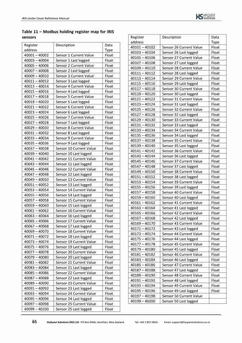
iRIS Under Cover Reference Manual
65 HyQuest Solutions (NZ) Ltd - PO Box 9466, Hamilton, New Zealand Tel: +64 7 857-0810 Email: [email protected]
Table 11 – Modbus holding register map for iRIS sensors
Register address
Description Data Type
40001 – 40002 Sensor 1 Current Value Float
40003 – 40004 Sensor 1 Last logged Float
40005 – 40006 Sensor 2 Current Value Float
40007 – 40008 Sensor 2 Last logged Float
40009 – 40010 Sensor 3 Current Value Float
40011 – 40012 Sensor 3 Last logged Float
40013 – 40014 Sensor 4 Current Value Float
40015 – 40016 Sensor 4 Last logged Float
40017 – 40018 Sensor 5 Current Value Float
40019 – 40020 Sensor 5 Last logged Float
40021 – 40022 Sensor 6 Current Value Float
40023 – 40024 Sensor 6 Last logged Float
40025 – 40026 Sensor 7 Current Value Float
40027 – 40028 Sensor 7 Last logged Float
40029 – 40030 Sensor 8 Current Value Float
40031 – 40032 Sensor 8 Last logged Float
40033 – 40034 Sensor 9 Current Value Float
40035 – 40036 Sensor 9 Last logged Float
40037 – 40038 Sensor 10 Current Value Float
40039 – 40040 Sensor 10 Last logged Float
40041 – 40042 Sensor 11 Current Value Float
40043 – 40044 Sensor 11 Last logged Float
40045 – 40046 Sensor 12 Current Value Float
40047 – 40048 Sensor 12 Last logged Float
40049 – 40050 Sensor 13 Current Value Float
40051 – 40052 Sensor 13 Last logged Float
40053 – 40054 Sensor 14 Current Value Float
40055 – 40056 Sensor 14 Last logged Float
40057 – 40058 Sensor 15 Current Value Float
40059 – 40060 Sensor 15 Last logged Float
40061 – 40062 Sensor 16 Current Value Float
40063 – 40064 Sensor 16 Last logged Float
40065 – 40066 Sensor 17 Current Value Float
40067 – 40068 Sensor 17 Last logged Float
40069 – 40070 Sensor 18 Current Value Float
40071 – 40072 Sensor 18 Last logged Float
40073 – 40074 Sensor 19 Current Value Float
40075 – 40076 Sensor 19 Last logged Float
40077 – 40078 Sensor 20 Current Value Float
40079 – 40080 Sensor 20 Last logged Float
40081 – 40082 Sensor 21 Current Value Float
40083 – 40084 Sensor 21 Last logged Float
40085 – 40086 Sensor 22 Current Value Float
40087 – 40088 Sensor 22 Last logged Float
40089 – 40090 Sensor 23 Current Value Float
40091 – 40092 Sensor 23 Last logged Float
40093 – 40094 Sensor 24 Current Value Float
40095 – 40096 Sensor 24 Last logged Float
40097 – 40098 Sensor 25 Current Value Float
40099 – 40100 Sensor 25 Last logged Float
Register address
Description Data Type
40101 – 40102 Sensor 26 Current Value Float
40103 – 40104 Sensor 26 Last logged Float
40105 – 40106 Sensor 27 Current Value Float
40107 – 40108 Sensor 27 Last logged Float
40109 – 40110 Sensor 28 Current Value Float
40111 – 40112 Sensor 28 Last logged Float
40113 – 40114 Sensor 29 Current Value Float
40115 – 40116 Sensor 29 Last logged Float
40117 – 40118 Sensor 30 Current Value Float
40119 – 40120 Sensor 30 Last logged Float
40121 – 40122 Sensor 31 Current Value Float
40123 – 40124 Sensor 31 Last logged Float
40125 – 40126 Sensor 32 Current Value Float
40127 – 40128 Sensor 32 Last logged Float
40129 – 40130 Sensor 33 Current Value Float
40131 – 40132 Sensor 33 Last logged Float
40133 – 40134 Sensor 34 Current Value Float
40135 – 40136 Sensor 34 Last logged Float
40137 – 40138 Sensor 35 Current Value Float
40139 – 40140 Sensor 35 Last logged Float
40141 – 40142 Sensor 36 Current Value Float
40143 – 40144 Sensor 36 Last logged Float
40145 – 40146 Sensor 37 Current Value Float
40147 – 40148 Sensor 37 Last logged Float
40149 – 40150 Sensor 38 Current Value Float
40151 – 40152 Sensor 38 Last logged Float
40153 – 40154 Sensor 39 Current Value Float
40155 – 40156 Sensor 39 Last logged Float
40157 – 40158 Sensor 40 Current Value Float
40159 – 40160 Sensor 40 Last logged Float
40161 – 40162 Sensor 41 Current Value Float
40163 – 40164 Sensor 41 Last logged Float
40165 – 40166 Sensor 42 Current Value Float
40167 – 40168 Sensor 42 Last logged Float
40169 – 40170 Sensor 43 Current Value Float
40171 – 40172 Sensor 43 Last logged Float
40173 – 40174 Sensor 44 Current Value Float
40175 – 40176 Sensor 44 Last logged Float
40177 – 40178 Sensor 45 Current Value Float
40179 – 40180 Sensor 45 Last logged Float
40181 – 40182 Sensor 46 Current Value Float
40183 – 40184 Sensor 46 Last logged Float
40185 – 40186 Sensor 47 Current Value Float
40187 – 40188 Sensor 47 Last logged Float
40189 – 40190 Sensor 48 Current Value Float
40191 – 40192 Sensor 48 Last logged Float
40193 – 40194 Sensor 49 Current Value Float
40195 – 40196 Sensor 49 Last logged Float
40197 – 40198 Sensor 50 Current Value
40199 – 40200 Sensor 50 Last logged
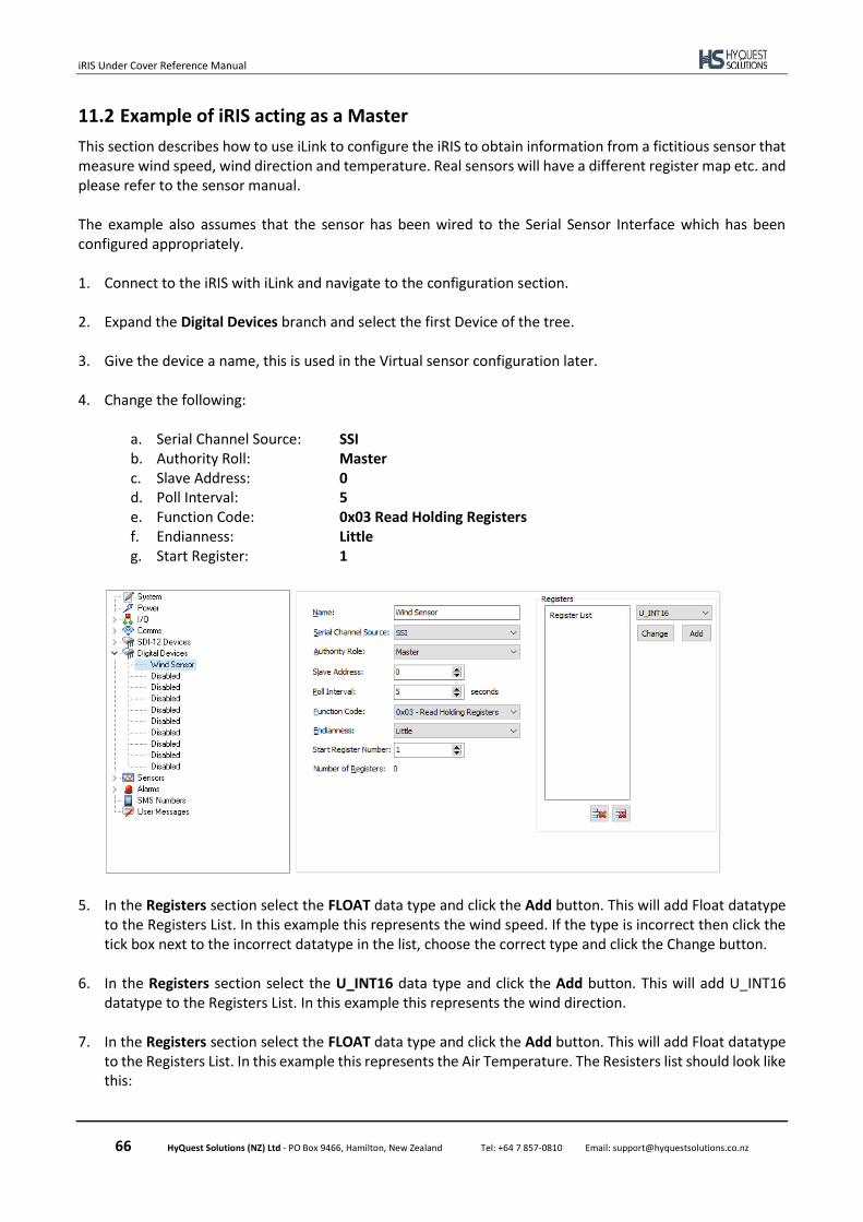
iRIS Under Cover Reference Manual
66 HyQuest Solutions (NZ) Ltd - PO Box 9466, Hamilton, New Zealand Tel: +64 7 857-0810 Email: [email protected]
11.2 Example of iRIS acting as a Master
This section describes how to use iLink to configure the iRIS to obtain information from a fictitious sensor that measure wind speed, wind direction and temperature. Real sensors will have a different register map etc. and please refer to the sensor manual. The example also assumes that the sensor has been wired to the Serial Sensor Interface which has been configured appropriately. 1. Connect to the iRIS with iLink and navigate to the configuration section.
2. Expand the Digital Devices branch and select the first Device of the tree.
3. Give the device a name, this is used in the Virtual sensor configuration later.
4. Change the following:
a. Serial Channel Source: SSI b. Authority Roll: Master c. Slave Address: 0 d. Poll Interval: 5 e. Function Code: 0x03 Read Holding Registers f. Endianness: Little g. Start Register: 1
5. In the Registers section select the FLOAT data type and click the Add button. This will add Float datatype to the Registers List. In this example this represents the wind speed. If the type is incorrect then click the tick box next to the incorrect datatype in the list, choose the correct type and click the Change button.
6. In the Registers section select the U_INT16 data type and click the Add button. This will add U_INT16 datatype to the Registers List. In this example this represents the wind direction.
7. In the Registers section select the FLOAT data type and click the Add button. This will add Float datatype
to the Registers List. In this example this represents the Air Temperature. The Resisters list should look like this:
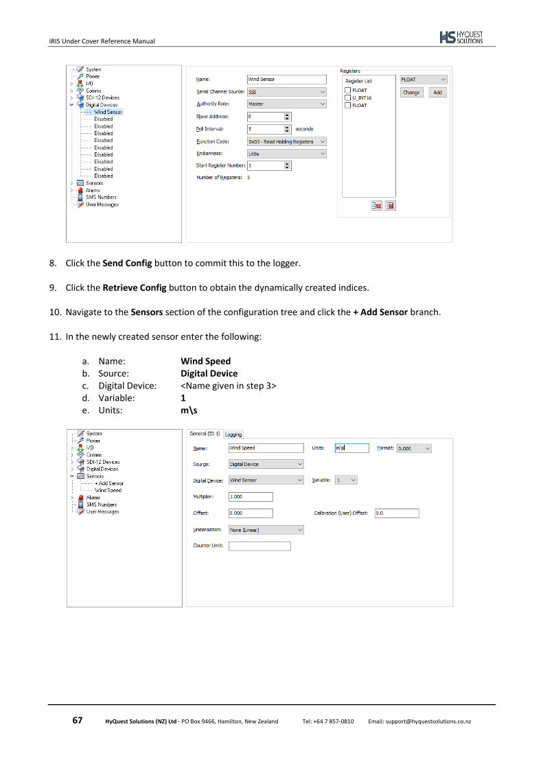
iRIS Under Cover Reference Manual
67 HyQuest Solutions (NZ) Ltd - PO Box 9466, Hamilton, New Zealand Tel: +64 7 857-0810 Email: [email protected]
8. Click the Send Config button to commit this to the logger.
9. Click the Retrieve Config button to obtain the dynamically created indices.
10. Navigate to the Sensors section of the configuration tree and click the + Add Sensor branch.
11. In the newly created sensor enter the following: a. Name: Wind Speed b. Source: Digital Device c. Digital Device: <Name given in step 3> d. Variable: 1 e. Units: m\s
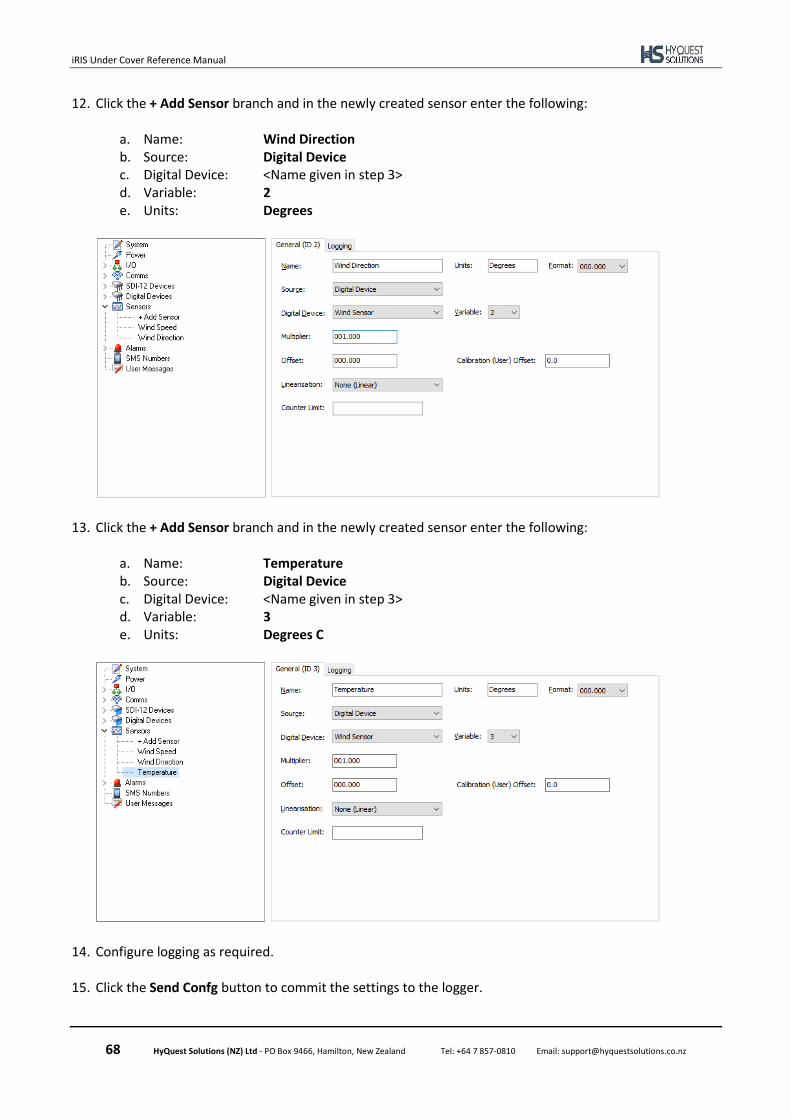
iRIS Under Cover Reference Manual
68 HyQuest Solutions (NZ) Ltd - PO Box 9466, Hamilton, New Zealand Tel: +64 7 857-0810 Email: [email protected]
12. Click the + Add Sensor branch and in the newly created sensor enter the following: a. Name: Wind Direction b. Source: Digital Device c. Digital Device: <Name given in step 3> d. Variable: 2 e. Units: Degrees
13. Click the + Add Sensor branch and in the newly created sensor enter the following: a. Name: Temperature b. Source: Digital Device c. Digital Device: <Name given in step 3> d. Variable: 3 e. Units: Degrees C
14. Configure logging as required.
15. Click the Send Confg button to commit the settings to the logger.
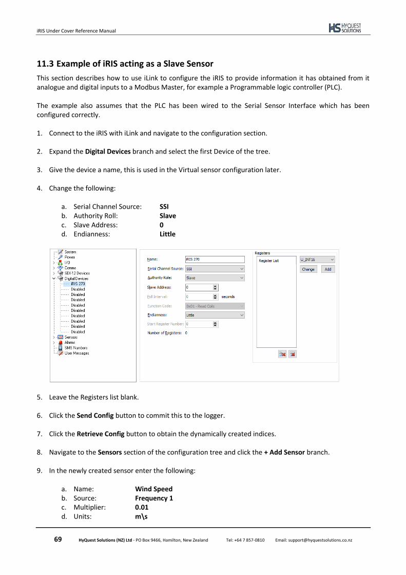
iRIS Under Cover Reference Manual
69 HyQuest Solutions (NZ) Ltd - PO Box 9466, Hamilton, New Zealand Tel: +64 7 857-0810 Email: [email protected]
11.3 Example of iRIS acting as a Slave Sensor
This section describes how to use iLink to configure the iRIS to provide information it has obtained from it analogue and digital inputs to a Modbus Master, for example a Programmable logic controller (PLC). The example also assumes that the PLC has been wired to the Serial Sensor Interface which has been configured correctly. 1. Connect to the iRIS with iLink and navigate to the configuration section.
2. Expand the Digital Devices branch and select the first Device of the tree.
3. Give the device a name, this is used in the Virtual sensor configuration later.
4. Change the following:
a. Serial Channel Source: SSI b. Authority Roll: Slave c. Slave Address: 0 d. Endianness: Little
5. Leave the Registers list blank.
6. Click the Send Config button to commit this to the logger.
7. Click the Retrieve Config button to obtain the dynamically created indices.
8. Navigate to the Sensors section of the configuration tree and click the + Add Sensor branch.
9. In the newly created sensor enter the following: a. Name: Wind Speed b. Source: Frequency 1 c. Multiplier: 0.01 d. Units: m\s
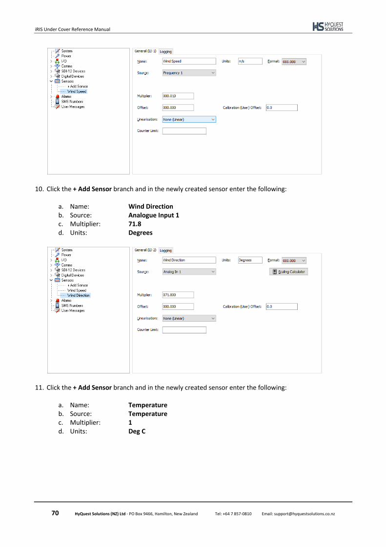
iRIS Under Cover Reference Manual
70 HyQuest Solutions (NZ) Ltd - PO Box 9466, Hamilton, New Zealand Tel: +64 7 857-0810 Email: [email protected]
10. Click the + Add Sensor branch and in the newly created sensor enter the following: a. Name: Wind Direction b. Source: Analogue Input 1 c. Multiplier: 71.8 d. Units: Degrees
11. Click the + Add Sensor branch and in the newly created sensor enter the following: a. Name: Temperature b. Source: Temperature c. Multiplier: 1 d. Units: Deg C

iRIS Under Cover Reference Manual
71 HyQuest Solutions (NZ) Ltd - PO Box 9466, Hamilton, New Zealand Tel: +64 7 857-0810 Email: [email protected]
12. Configure logging as required.
13. Click the Send Confg button to commit the settings to the logger.
14. Configure the PLC to poll the logger with the following details: a. Function: Read Multiple Holding Registers b. Slave Address: 0 c. Register address: 40001 or 0 (depends on PLC operation) d. Number of registers to retrieve: 1217 e. Register data type: Single precision float
The data retrieved by the PLC will be in the following order and have the meaning described in the table:
Holding Register Register Address Value
40001 – 40002 0 – 1 Current Wind Speed
40003 – 40003 2 – 3 Last logged Wind Speed
40005 – 40006 4 – 4 Current Wind Direction
40007 – 40008 6 – 5 Last logged Wind Direction
40009 – 400010 8 – 7 Current Temperature
400011 – 400012 10 – 11 Last logged Temperature
17 The number of registers is calculated from the number of sensors to be obtained x 2 (current value and last logged) x 2 (number of registers per float data type). In this example the number of registers is 3 x 2 x 2 = 12.
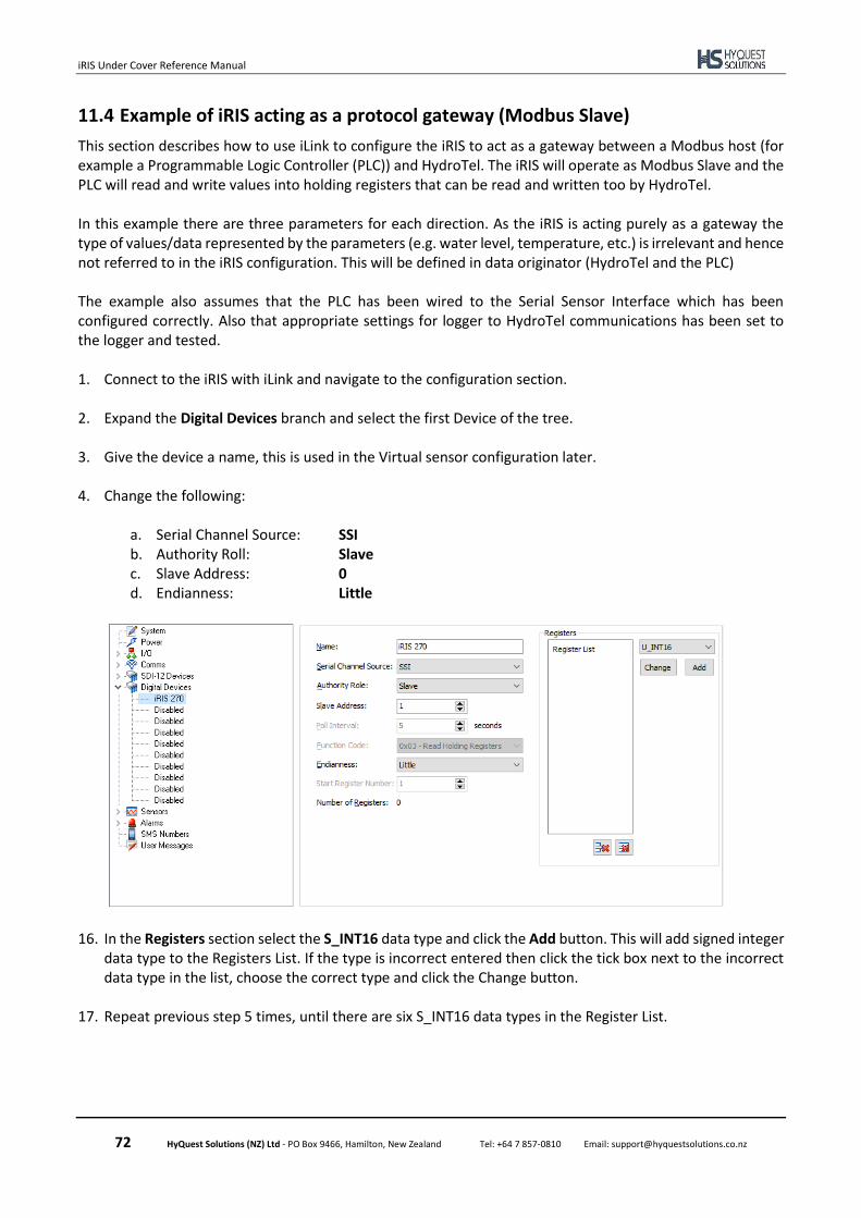
iRIS Under Cover Reference Manual
72 HyQuest Solutions (NZ) Ltd - PO Box 9466, Hamilton, New Zealand Tel: +64 7 857-0810 Email: [email protected]
11.4 Example of iRIS acting as a protocol gateway (Modbus Slave)
This section describes how to use iLink to configure the iRIS to act as a gateway between a Modbus host (for example a Programmable Logic Controller (PLC)) and HydroTel. The iRIS will operate as Modbus Slave and the PLC will read and write values into holding registers that can be read and written too by HydroTel. In this example there are three parameters for each direction. As the iRIS is acting purely as a gateway the type of values/data represented by the parameters (e.g. water level, temperature, etc.) is irrelevant and hence not referred to in the iRIS configuration. This will be defined in data originator (HydroTel and the PLC) The example also assumes that the PLC has been wired to the Serial Sensor Interface which has been configured correctly. Also that appropriate settings for logger to HydroTel communications has been set to the logger and tested. 1. Connect to the iRIS with iLink and navigate to the configuration section.
2. Expand the Digital Devices branch and select the first Device of the tree.
3. Give the device a name, this is used in the Virtual sensor configuration later.
4. Change the following:
a. Serial Channel Source: SSI b. Authority Roll: Slave c. Slave Address: 0 d. Endianness: Little
16. In the Registers section select the S_INT16 data type and click the Add button. This will add signed integer data type to the Registers List. If the type is incorrect entered then click the tick box next to the incorrect data type in the list, choose the correct type and click the Change button.
17. Repeat previous step 5 times, until there are six S_INT16 data types in the Register List.
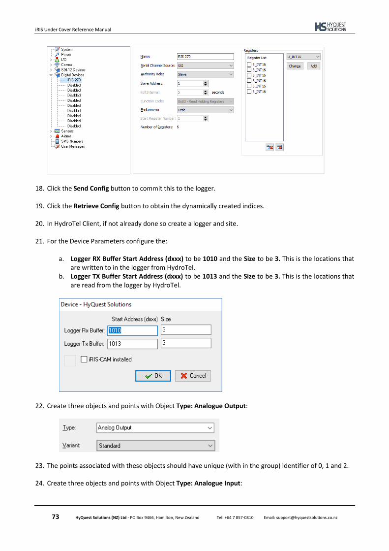
iRIS Under Cover Reference Manual
73 HyQuest Solutions (NZ) Ltd - PO Box 9466, Hamilton, New Zealand Tel: +64 7 857-0810 Email: [email protected]
18. Click the Send Config button to commit this to the logger.
19. Click the Retrieve Config button to obtain the dynamically created indices.
20. In HydroTel Client, if not already done so create a logger and site.
21. For the Device Parameters configure the: a. Logger RX Buffer Start Address (dxxx) to be 1010 and the Size to be 3. This is the locations that
are written to in the logger from HydroTel. b. Logger TX Buffer Start Address (dxxx) to be 1013 and the Size to be 3. This is the locations that
are read from the logger by HydroTel.
22. Create three objects and points with Object Type: Analogue Output:
23. The points associated with these objects should have unique (with in the group) Identifier of 0, 1 and 2.
24. Create three objects and points with Object Type: Analogue Input:

iRIS Under Cover Reference Manual
74 HyQuest Solutions (NZ) Ltd - PO Box 9466, Hamilton, New Zealand Tel: +64 7 857-0810 Email: [email protected]
25. The points associated with these objects should have unique (with in the group) Identifier of 0,1 and 2.
15. Configure the PLC to poll the logger with the following details: a. Function: Write Multiple Holding Registers b. Slave Address: 0 c. Register address: 40201 or 200 (depends on PLC operation) d. Number of registers to write: 3 e. Register data type: Signed 16-bit Integer
16. Configure the PLC to poll the logger with the following details:
a. Function: Read Multiple Holding Registers b. Slave Address: 0 c. Register address: 40204 or 203 (depends on PLC operation) d. Number of registers to retrieve: 3 e. Register data type: Signed 16 bit Integer
The configuration is complete. To aid in understanding the data flow in this example the following table may act as a visualisation. The Objects listed are those created above (the actual names will different in reality, for example Gate height SP, etc.).
HydroTel iRIS PLC
Object Point ID Function d Location Modbus Reg Modbus Addr Function
Analogue Out A 0
Write →
1010 40201 200
→Read Analogue Out B 1 1011 40202 201
Analogue Out C 2 1012 40203 202
Analogue In A 0
Read
1013 40204 203
Write Analogue In B 1 1014 40205 204
Analogue In C 2 1015 40206 205
Table 12 – Data flow visualisation of the Modbus gateway example
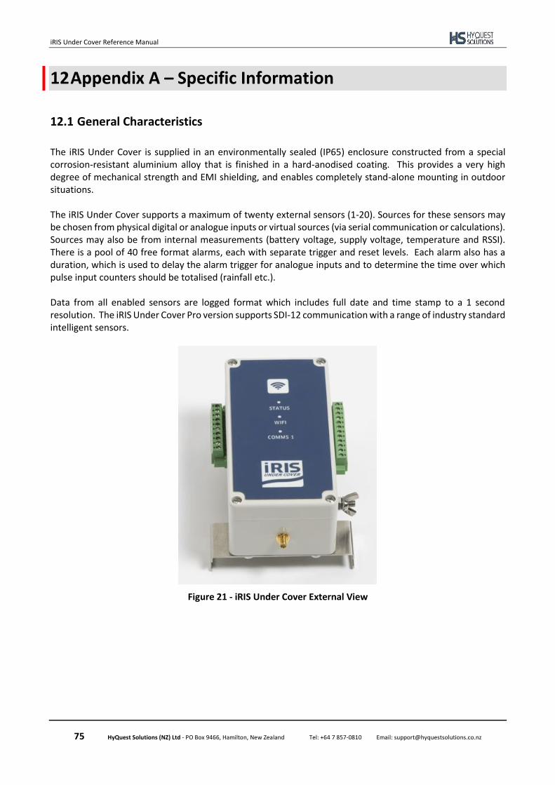
iRIS Under Cover Reference Manual
75 HyQuest Solutions (NZ) Ltd - PO Box 9466, Hamilton, New Zealand Tel: +64 7 857-0810 Email: [email protected]
12 Appendix A – Specific Information
12.1 General Characteristics
The iRIS Under Cover is supplied in an environmentally sealed (IP65) enclosure constructed from a special corrosion-resistant aluminium alloy that is finished in a hard-anodised coating. This provides a very high degree of mechanical strength and EMI shielding, and enables completely stand-alone mounting in outdoor situations. The iRIS Under Cover supports a maximum of twenty external sensors (1-20). Sources for these sensors may be chosen from physical digital or analogue inputs or virtual sources (via serial communication or calculations). Sources may also be from internal measurements (battery voltage, supply voltage, temperature and RSSI). There is a pool of 40 free format alarms, each with separate trigger and reset levels. Each alarm also has a duration, which is used to delay the alarm trigger for analogue inputs and to determine the time over which pulse input counters should be totalised (rainfall etc.). Data from all enabled sensors are logged format which includes full date and time stamp to a 1 second resolution. The iRIS Under Cover Pro version supports SDI-12 communication with a range of industry standard intelligent sensors.
Figure 21 - iRIS Under Cover External View
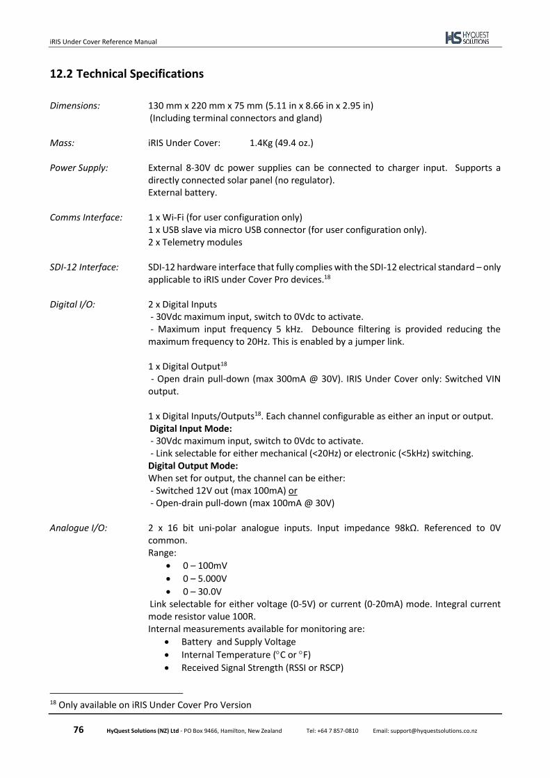
iRIS Under Cover Reference Manual
76 HyQuest Solutions (NZ) Ltd - PO Box 9466, Hamilton, New Zealand Tel: +64 7 857-0810 Email: [email protected]
12.2 Technical Specifications
Dimensions: 130 mm x 220 mm x 75 mm (5.11 in x 8.66 in x 2.95 in) (Including terminal connectors and gland) Mass: iRIS Under Cover: 1.4Kg (49.4 oz.) Power Supply: External 8-30V dc power supplies can be connected to charger input. Supports a
directly connected solar panel (no regulator). External battery. Comms Interface: 1 x Wi-Fi (for user configuration only) 1 x USB slave via micro USB connector (for user configuration only). 2 x Telemetry modules SDI-12 Interface: SDI-12 hardware interface that fully complies with the SDI-12 electrical standard – only
applicable to iRIS under Cover Pro devices.18 Digital I/O: 2 x Digital Inputs
- 30Vdc maximum input, switch to 0Vdc to activate. - Maximum input frequency 5 kHz. Debounce filtering is provided reducing the maximum frequency to 20Hz. This is enabled by a jumper link. 1 x Digital Output18 - Open drain pull-down (max 300mA @ 30V). IRIS Under Cover only: Switched VIN
output.
1 x Digital Inputs/Outputs18. Each channel configurable as either an input or output. Digital Input Mode:
- 30Vdc maximum input, switch to 0Vdc to activate. - Link selectable for either mechanical (<20Hz) or electronic (<5kHz) switching. Digital Output Mode: When set for output, the channel can be either: - Switched 12V out (max 100mA) or - Open-drain pull-down (max 100mA @ 30V)
Analogue I/O: 2 x 16 bit uni-polar analogue inputs. Input impedance 98kΩ. Referenced to 0V
common. Range:
• 0 – 100mV
• 0 – 5.000V
• 0 – 30.0V Link selectable for either voltage (0-5V) or current (0-20mA) mode. Integral current mode resistor value 100R. Internal measurements available for monitoring are:
• Battery and Supply Voltage
• Internal Temperature (C or F)
• Received Signal Strength (RSSI or RSCP)
18 Only available on iRIS Under Cover Pro Version
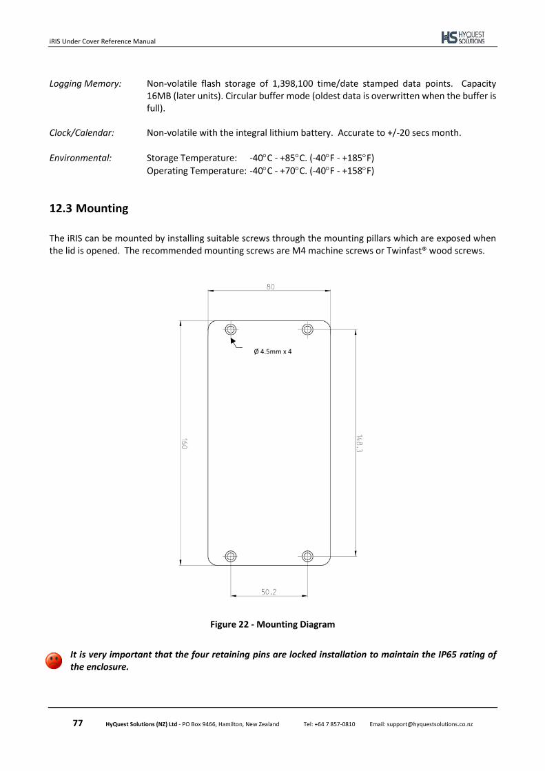
iRIS Under Cover Reference Manual
77 HyQuest Solutions (NZ) Ltd - PO Box 9466, Hamilton, New Zealand Tel: +64 7 857-0810 Email: [email protected]
Logging Memory: Non-volatile flash storage of 1,398,100 time/date stamped data points. Capacity
16MB (later units). Circular buffer mode (oldest data is overwritten when the buffer is full).
Clock/Calendar: Non-volatile with the integral lithium battery. Accurate to +/-20 secs month.
Environmental: Storage Temperature: -40C - +85C. (-40F - +185F)
Operating Temperature: -40C - +70C. (-40F - +158F)
12.3 Mounting
The iRIS can be mounted by installing suitable screws through the mounting pillars which are exposed when the lid is opened. The recommended mounting screws are M4 machine screws or Twinfast® wood screws.
Figure 22 - Mounting Diagram
It is very important that the four retaining pins are locked installation to maintain the IP65 rating of the enclosure.
Ø 4.5mm x 4
iRIS Under Cover Reference Manual
78 HyQuest Solutions (NZ) Ltd - PO Box 9466, Hamilton, New Zealand Tel: +64 7 857-0810 Email: [email protected]
13 Appendix B – Upgrading Firmware
13.1 Overview
This section describes the procedure to use when upgrading the firmware component in an iRIS.
The upgrade procedure has been carried out many times without issue. However, because the process does involve erasing and reprogramming of flash memory, it is important that a good, securely connected power supply is provided to the iRIS throughout the upgrade process.
13.2 File Naming Conventions
13.2.1 iRIS Executive Firmware
The iRIS firmware is available as a single file for downloading and flash upgrading using iLink 2012. The upgrade file is in the format: iRISUnderCover_x-y-z.bin where: x-y-z is the firmware version:
x – Major version y – Minor version z – Build version
e.g. iRISUnderCover_1-0-0.bin iRIS Under Cover Firmware, 1.0.0 The default repository for the firmware files is C:\ProgramData\iQuest\iLink2\Programs.
13.3 Active verse Pending Firmware
There are up to two copies of firmware stored on the iRIS, they are stored in the Active and Pending regions of non-volatile memory. The version information for both of these areas can be obtained using iLink.
Active – current running firmware image.
Pending – the area containing firmware image that will be used to upgrade the Active area or used as a backup if the Active area is corrupted. It is a landing area for new firmware to be placed while the operation of the logger is not affected, thus allowing for interruptions to communications a power. Upon completion of upload of a new firmware file, the activate command is sent to the logger, invalidating the Active area and forcing c copy of the pending area to the Active. A pending version of preceded with a 9 indicates that the firmware is partially uploaded to the logger. For example, 91.4.3 indicates that version 1.4.3 of the firmware is part way through being uploaded to the logger

iRIS Under Cover Reference Manual
79 HyQuest Solutions (NZ) Ltd - PO Box 9466, Hamilton, New Zealand Tel: +64 7 857-0810 Email: [email protected]
13.4 iRIS Automated Upgrade Procedure (Firmware)
iLink 2012 has an automated firmware upgrade tool that supports the iRIS Under Cover. This tool includes several checks to confirm the validity of the components being installed. The automated upgrade tool will automatically select the latest version of firware. The example given below shows a full, automatic firmware upgrade for an iRIS Under Cover.
1. Make sure the required upgrade files are available on the computer. Ideally these should be located
in the default deployment folders listed above in Section 13.2.
2. Connect to the iRIS using iLink 2012.
3. Click the Program button under the button under the Configuration tab.
4. Click the Auto Upgrade button.
5. Click OK to load the selected programs to the device. The progress of the upgrade can be seen on
the status bar.
6. Once the process is completed, you can see a message saying "Upgrade completed successfully" on
the status bar and the iLink 2012 window will show the current software status of the device.

iRIS Under Cover Reference Manual
80 HyQuest Solutions (NZ) Ltd - PO Box 9466, Hamilton, New Zealand Tel: +64 7 857-0810 Email: [email protected]
13.5 iRIS Manual Upgrade Procedure (Firmware)
iLink 2012 also allows you to upgrade the software and firmware manually. Please go through the below steps to do a manual upgrade of software and firmware for the iRIS.
1. Make sure the required upgrade files are available on the computer. Ideally these should be located
in the default deployment folders listed above in Section 13.2.
2. Connect to the iRIS using iLink 2012.
3. Click the Program button under the button under the Configuration tab.
4. Click on the Manual Upgrade.
5. Select the new firmware file using the firmware browse button.
6. Click OK to load the selected programs to the device.
7. Once the process is completed, you can see a message saying "Upgrade completed successfully" on
the status bar and the iLink 2012 window will show the current software status of the device.
8. Click the Activate button to commit the new firmware to the unit overwriting current version.

iRIS Under Cover Reference Manual
81 HyQuest Solutions (NZ) Ltd - PO Box 9466, Hamilton, New Zealand Tel: +64 7 857-0810 Email: [email protected]
14 APPENDIX C – SDI-12
14.1 What is SDI-12?
SDI-12 stands for Serial Digital Interface at 1200 bps. It is a standard to interface battery powered data recorders with microprocessor-based sensors designed for environmental data acquisition (EDA). EDA is accomplished by means of a sensor, or sensors, and a data recorder, which collects and saves the data. SDI-12 is a standard communications protocol, which provides a means to transfer measurements taken by an intelligent sensor to a data recorder. An intelligent sensor typically takes a measurement, makes computations based on the raw sensor reading, and outputs the measured data in engineering units. For example, an SDI-12 pressure sensor may take a series of pressure measurements, average them, and then output pressure in psi, inches of mercury, bars, millibars, or torrs. The sensor's microprocessor makes the computations, converts sensor readings into the appropriate units, and uses the SDI-12 protocol to transfer data to the recorder. SDI-12 is a multi-drop interface that can communicate with multi-parameter sensors. Multi-drop means that more than one SDI-12 sensor can be connected to a data recorder. The SDI-12 bus is capable of having ten sensors connected to it. Having more than ten sensors, however, is possible. Some SDI-12 users connect more than ten sensors to a single data recorder. Multi-parameter means that a single sensor may return more than one measurement. For example, some water quality sensors return temperature, conductivity, dissolved oxygen, pH, turbidity, and depth.
14.2 Advantages of SDI-12
A serial-digital interface is a logical choice for interfacing microprocessor-based sensors with a data recorder. This has advantages for sensors and data recorders.
• Unique and complex self-calibration algorithms can be done in microprocessor-based sensors.
• Sensors can be interchanged without reprogramming the data recorder with calibration or other information.
• Power is supplied to sensors through the interface.
• Hybrid circuit and surface mount technologies make it practical to include the power supply regulator, a microprocessor, and other needed circuitry in small sensor packages.
• Sensors can use low cost EEPROMs (electrically erasable programmable read only memory) for calibration coefficients and other information instead of internal trimming operations.
• The use of a standard serial interface eliminates significant complexity in the design of data recorders.
• Data recorders can be designed and produced independently of future sensor development.
• SDI-12 data recorders interface with a variety of sensors.
• SDI-12 sensors interface with a variety of data recorders.
• Personnel trained in SDI-12 will have skills to work with a variety of SDI-12 data recorders and SDI-12 sensors.

iRIS Under Cover Reference Manual
82 HyQuest Solutions (NZ) Ltd - PO Box 9466, Hamilton, New Zealand Tel: +64 7 857-0810 Email: [email protected]
14.3 SDI-12 Electrical Interface
The SDI-12 electrical interface uses the SDI-12 bus to transmit serial data between SDI-12 data recorders and sensors. The SDI-12 bus is the cable that connects multiple SDI-12 devices. This is a cable with three conductors:
1) A serial data line 2) A ground line 3) A 12-volt line
In the following specifications, all values not indicating specific limits have an allowable tolerance of ±10% of the value. The SDI-12 bus is capable of having at least 10 sensors connected to it.
14.3.1 Serial Data Line
The data line is a bi-directional, three-state data transfer line. Table 13 shows the logic and voltage levels for the transmission of serial data for the SDI-12 standard. The data line uses negative logic.
Condition Binary state Voltage range Marking 1 -0.5 to 1.0 volts Spacing 0 3.5 to 5.5 volts Transition undefined 1.0 to 3.5 volts
Table 13 – Logic and voltage levels for serial data on SDI-12 bus
Voltage Transitions During normal operation, the data line voltage slew rate must not be greater than 1.5 volts per microsecond.
14.3.2 Ground Line
The ground line must be connected to the circuit ground and the earth ground at the data recorder. The sensor circuit ground also must be connected to the ground line, but not normally to its own earth ground. If it is necessary to connect the sensor circuitry to earth ground, a heavy (12 AWG or larger) ground wire should be connected between the sensor earth ground and the data recorder earth ground for lightning protection. The ground conductor should be large enough to keep the voltage drop between the data recorder and all sensors less than 0.5 volts during the maximum combined sensor current drain.
14.3.3 Volt-Line
The data recorder (or the external power supply) provides between 9.6 volts and 16 volts to the 12-volt line, with respect to ground, as measured under a maximum sensor load of 0.5 amperes. SDI-12 does not require the data recorder to be the source of power to the 12-volt line. Sensors connected to the 12-volt line must not have inductive loads. SDI-12 does not require voltage limiting for transient protection in the sensor. Transient protection is however recommended. Note: This information is taken from:
SDI-12 Serial-Digital Interface Standard for Microprocessor-Based Sensors, Version 1.3 – January 28, 2016 Prepared By SDI-12 Support Group (Technical Committee)
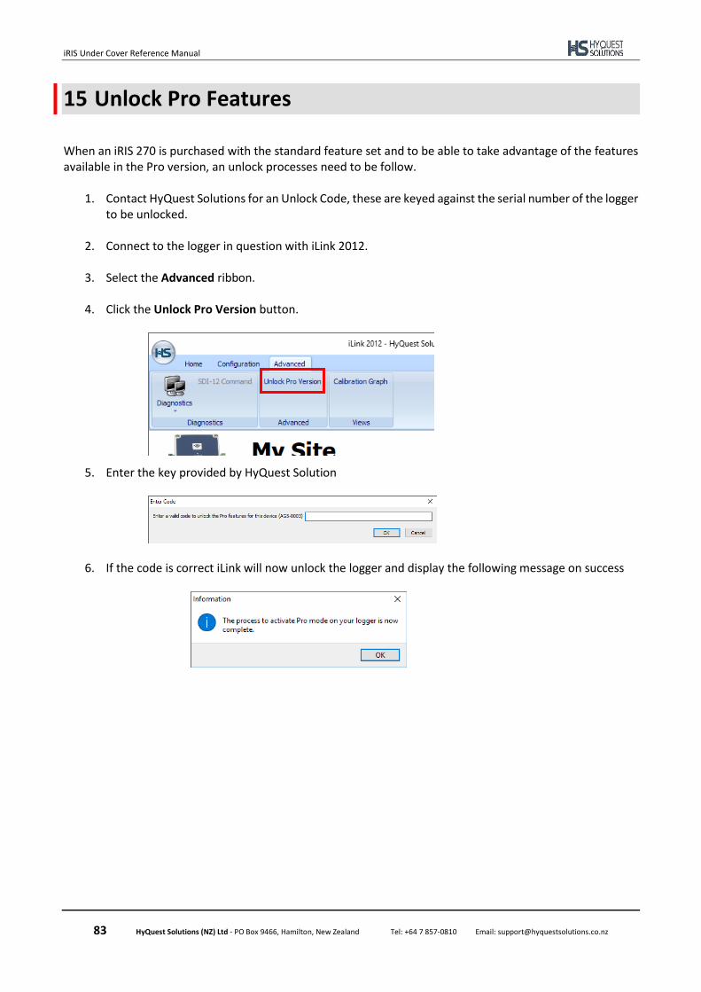
iRIS Under Cover Reference Manual
83 HyQuest Solutions (NZ) Ltd - PO Box 9466, Hamilton, New Zealand Tel: +64 7 857-0810 Email: [email protected]
15 Unlock Pro Features
When an iRIS 270 is purchased with the standard feature set and to be able to take advantage of the features available in the Pro version, an unlock processes need to be follow.
1. Contact HyQuest Solutions for an Unlock Code, these are keyed against the serial number of the logger to be unlocked.
2. Connect to the logger in question with iLink 2012.
3. Select the Advanced ribbon.
4. Click the Unlock Pro Version button.
5. Enter the key provided by HyQuest Solution
6. If the code is correct iLink will now unlock the logger and display the following message on success

iRIS Under Cover Reference Manual
84 HyQuest Solutions (NZ) Ltd - PO Box 9466, Hamilton, New Zealand Tel: +64 7 857-0810 Email: [email protected]
16 User Notes