Embed Size (px)
Citation preview

IRIS Touch
Engineering Manual
Version 1.2

Page 2 of 48 IRIS Touch Engineering Manual Version 1.2
Contents 1. Introduction ....................................................................................................................................................... 3 2. IRIS Communication Mechanism (Polling / Alarms) .......................................................................................... 4 3. Product Features ............................................................................................................................................... 5 4. Package Contents .............................................................................................................................................. 6 5. Board Configuration .......................................................................................................................................... 6 6. Before You Start ................................................................................................................................................. 7 7. Installing the IRIS Touch Dialler ......................................................................................................................... 8
7.1. Mounting .............................................................................................................................................. 8 7.2. Power .................................................................................................................................................... 8 7.3. Connections .......................................................................................................................................... 8 7.4. GPRS/3G SIM card (IRIS Touch 400NG or 440NG) .............................................................................. 10 7.5. Dial Capture ........................................................................................................................................ 10 7.6. Pin Inputs ............................................................................................................................................ 10 7.7. Expansion Board + PSTN (sold separately) ......................................................................................... 11 7.8. Switch On and Test ............................................................................................................................. 11 7.9. Configuration ...................................................................................................................................... 12
7.10. Panel Configuration ............................................................................................................................ 13 7.11. Testing ................................................................................................................................................. 16
8. Main menu ....................................................................................................................................................... 16 8.1. Installation Wizard .............................................................................................................................. 16 8.2. Settings ............................................................................................................................................... 21 8.3. Test...................................................................................................................................................... 35 8.4. Run Network Scan ............................................................................................................................... 37
9. Trouble report.................................................................................................................................................. 38 10. Installation for VdS 2463 Compliance .............................................................................................................. 39
10.1. Introduction ........................................................................................................................................ 39 10.2. Installation for VdS2463 compliance .................................................................................................. 39
11. Installation for EN54-21 Compliant Fire Applications ..................................................................................... 43 11.1. Introduction ........................................................................................................................................ 43 11.2. General description of the equipment ............................................................................................... 43 11.3. Installation, Configuration and Commissioning .................................................................................. 43
12. Maintenance .................................................................................................................................................... 45 12.1. Confirm Current Status ....................................................................................................................... 45 12.2. Check Software Version / Reflash ....................................................................................................... 45 12.3. Communication Paths Checks ............................................................................................................. 45 12.4. Test Alarm Panel Alarms and Communication to ARC ....................................................................... 45
13. Specifications ................................................................................................................................................... 46

IRIS Touch Engineering Manual Version 1.2 Page 3 of 48
1. Introduction
The IRIS Touch offers cost effective Alarm over IP (AoIP) for the commercial and residential sectors.
All IRIS Touch diallers are certified as suitable for all Grade 4 systems with an Alarm Transmission System (ATS) configuration up to SP6 for single path, or ATS configuration DP4 for dual path (IRIS Touch 440NG only).
The IRIS Touch is based on Chiron’s successful IRIS Touch range of AoIP diallers with the same hardware and software used in all IRIS diallers; with the same level of security and features provided to military, governments, banks and commercial industry markets.
The IRIS Touch offers a touch screen as standard for configuration, local alerts, and allows diagnostic and tests to be performed by the engineer.
Polling and alarm transmission are performed via the Ethernet or GPRS/3G communication paths (4G and CDMA on request) to the monitoring centre using the IRIS Secure Apps monitoring software.
Page 4 of 48 IRIS Touch Engineering Manual Version 1.2
2. IRIS Communication Mechanism (Polling / Alarms)
The polling / alarm mechanism used on the Chiron IRIS system is highly secure and flexible, and uses the IRIS Secure Apps monitoring software (installed at the monitoring centres) with the IRIS Touch diallers.
It has been independently certified as compliant to the highest level of security available – Grade 4, ATS6 - within the EN50131 standard for alarm systems.
The IRIS system is unique in its ability for the polling frequency to be varied which means that the polling profile can be adjusted as necessary to take into account the grade of security required and the traffic bandwidth available.
Key features are:
Independently certified as compliant with EN50131-1 Grade 4 ATS configuration SP6 over Ethernet and ATS – SP5 over GPRS for single path Ethernet and DP4 for dual path communications.
After initial installation all backup or alternate IP address for the Polling engines (main & backup) are downloaded to the IRIS Touch dialler over the polling communications.
All polling and alarms are authenticated by the receiver (Polling Engine) using the secure and sophisticated ‘Challenge Handshake’ mechanism as used in military and credit card applications. Each remote IRIS dialler proves its authenticity using a 256 bit security key. A new random number generated by the receiver (Polling Engine) is used for every poll so it is not possible to substitute the dialler using playback or sequence prediction.
Unlike other systems each dialler can have a unique security key which can be changed at the monitoring centre any time as required. For additional security the installer never needs to load the key or be aware of what it is.
Also unlike other systems, the polling frequency is not fixed and can be varied by the monitoring centre at any time, from a period of 10 seconds for high security systems down to once a week for low security systems. This means that polling rates can be optimised to deliver the grade of service required and minimise the bandwidth required.
Polling and alarms are carried over the TCP/IP protocol that gives end-to-end error protection. This removes the possibility with other protocols such as UDP that data packets are lost or re-sequenced in the network leading to false alarms.
All polling and alarms are outbound from the dialler location to the monitoring centre and do not require the IP address of the dialler to be known. No special set-up is required at the customer’s router, such as port mapping for incoming calls. This feature is essential for operation with networks with dynamic addressing and standard GPRS/3G networks.
Background communication path polling is also configurable at the monitoring centre and enables the IRIS dialler to periodically poll over the backup communication path, and any faults with this communication will be reported back to the IRIS Secure Apps system.
Each poll transaction is very small and with the authentication protocol is only about 500 bytes of data, including all traffic in both directions. For fixed line IP networks there are no traffic costs.
Total traffic is proportional to the polling frequency. For example, at 10 second poll 180K bytes per hour and at 3 minutes polling this would reduce substantially to only 10K bytes per hour.
Even with tariffed networks such as GPRS/3G, and when running at a polling rate suitable for the highest level of security, a typical cost is only a few Euros per month. For GPRS/3G in many cases the level of traffic falls within the free bandwidth that comes with the SIM card contract and will effectively be at no cost.

IRIS Touch Engineering Manual Version 1.2 Page 5 of 48
3. Product Features
Features IRIS Touch
400NG 420NG 440NG
Touch Screen
Ethernet 2 2
GPRS/3G
Dial capture
Relays 4 4 4
Inputs (Pins) 4 standard + 12 with add-on expansion board
Serial RS485
Serial TTL
RS232 (Basic or Full) 1 x Full or 2 x Basic
CAN bus
Text messaging
Multi language menus
VoIP & SIP services
HVAC and Home Automation interface
Option available on request 4G / CDMA

Page 6 of 48 IRIS Touch Engineering Manual Version 1.2
4. Package Contents
Contents dependent on model type:
Dialler board
Ethernet cable (IRIS Touch 420NG & 440NG)
GPRS/3G antenna (IRIS Touch 400NG & 440NG)
Stylus
RJ11 cable
18k Ohms sense resistor
5. Board Configuration
IRIS Touch
SYS LED
LED Colour Indication
Yellow flashing Not currently configured or indicating that there are some current faults outstanding. See Section 9 “Trouble report”.
Yellow constant Communicating and no current faults (flickers on every poll).
DC power
Pin inputs
RS485
Dial capture port RJ11 and screw
terminals
SIM card holder
Ethernet 2
SYS LED
Ethernet 1
Expansion board connector
GPRS/3G antenna
Serial (TTL)
RS232 x 2
Relays Micro USB
External tamper
CAN bus
Touch screen

IRIS Touch Engineering Manual Version 1.2 Page 7 of 48
6. Before You Start
Monitoring Centre (ARC)
Make sure that the monitoring centre to which the IRIS Touch device will send alarm signals is equipped with the appropriate IRIS Secure Apps receiving system. The following information should be obtained from the monitoring centre.
Dialler account number
Monitoring centre IP address
Ethernet Connection Details
The customer’s Ethernet (LAN) network details are required in order to connect the IRIS Touch. The following information should be obtained from the customer.
Fixed IP address or DHCP Fixed DHCP
If using DHCP then the following information will not be required as it will be assigned by the network.
IP address
Gateway address
Subnet mask address
GPRS/3G SIM Card and Access Point Name
If the installation uses GPRS/3G then a SIM card will be required. The IRIS Touch will also need to be given a GPRS/3G ‘Access Point Name’ (APN) and other possible configurations as shown below. These can be obtained from the SIM card provider.
Access Point Name (APN)
User Name (USR)
Password (PWD)
SIM Pin

Page 8 of 48 IRIS Touch Engineering Manual Version 1.2
7. Installing the IRIS Touch Dialler
Use the following procedure to install your IRIS Touch dialler:
Mounting 7.1.
Choose a suitable location, taking into consideration the routing of both power and dialler interface cables, within the alarm panel or separate enclosure. Secure the dialler within the enclosure using the fitted standoff or the alternative self-adhesive feet.
Note: For EN50131-10 compliance you must use the supplied standoff and not the self-adhesive feet.
Power 7.2.
The IRIS Touch dialler can be powered from a separate or Aux 9-28V DC power supply specified to delivery up to 1A current using the screw terminals indicated in Section 5 “Board Configuration”.
Note: For Radio & Telecoms Terminal Equipment Directive compliance the power cable must be no longer than 3 meters in length.
Fit the power cable. DO NOT APPLY POWER TO THE DIALLER UNTIL INDICATED.
Connections 7.3.
Connect cables to the PCB for your system as shown on in Section 5 “Board Configuration”.
Ethernet enabled systems (IRIS Touch 420NG & 440NG): Ethernet socket ETH1.
Connect the Ethernet cable from ‘ETH1’ to the local IP router/switch or socket that has been allocated for the LAN/WAN network IP connection.
GPRS/3G enabled systems (IRIS Touch 400NG & 440NG): Cell Ant. Fit the supplied T-bar GPRS/3G antenna but do not fix in place until after performing the GPRS/3G network scan.
Note: An external GPRS/3G antenna can be fitted if required.
Dial capture port (optional and for more information see section below).
4 x Pin Inputs + expansion board for addition PIN inputs and PSTN dial out (optional and for more information see section below).
Optional serial connection
The following 5 connections are optional and depend on the panel connection method to be used.
By default the IRIS Touch RS485 connection is for Honeywell Galaxy panels and the Serial TTL header is for Texecom Premier panels. For alternative selections for other panel manufactures use the touch screen on the IRIS Touch Installers menu – settings to select the option required.
RS485 currently available for Honeywell Galaxy data bus (Alarms and Upload/download) or Risco ProSys bus (Upload/download) connections (optional).
Serial (TTL) currently available for Texecom Com1 connections (optional).
RS232 port 1 screw terminal (optional for Hayes command terminal).
RS232 port 2 screw terminal (optional for integrated panel connection).
CAN bus screw terminals (optional).
For more details on the cable requirements / connections please see detail on next page.

IRIS Touch Engineering Manual Version 1.2 Page 9 of 48
RS485 connections (Honeywell Galaxy or Risco ProSys)
IRIS Touch to Honeywell Galaxy panels
IRIS RS485 screw terminals To Galaxy Data Bus terminal
0V (Power) Galaxy (-)
VIN (Power) Galaxy (+)
A Galaxy (A)
B Galaxy (B)
IRIS Touch to Risco ProSys panels
IRIS RS485 screw terminals To Risco Bus1 terminal
0V (Power) COM
VIN (Power) AUX
A YEL
B GRN
TTL connections (Texecom Premier Range)
Can be ordered from Chiron
Description = Texecom RS232 Lead
Part No = Tex600
RS232 port 2 connections (HHL and ESPA)
IRIS Touch to HHL panels
IRIS RS232 screw terminals To HHL Com Port (X3)
TX2 2 (RX)
RX2 3 (TX)
0V 1 (GRD)
IRIS Touch to ESPA fire panels
IRIS RS232 screw terminals To DB9 Male connector (possible screw terminals)
TX2 Pin 2 (RX)
RX2 Pin 3 (TX)
0V Pin 5 (GRD)

Page 10 of 48 IRIS Touch Engineering Manual Version 1.2
Reference ground pins Pin inputs 1 4
GPRS/3G SIM card (IRIS Touch 400NG or 440NG) 7.4.
DO NOT FIT SIM card until after you have performed the GPRS/3G Network Scan detailed in the Section 7.9 “Configuration” you will be prompted when to insert the SIM card.
Dial Capture 7.5.
Dial capture enabled systems: Connect either the dial port RJ45 or the 2 dial screw terminals with the supplied RJ11 dialler cable to the alarm panel dialler telecoms line connection. If the alarm panel has screw connections, cut the connector off the cable and strip the cable using the 2 inner wires.
Note: Polarity is not important in this instance.
Fit the supplied 18K sense resistor in parallel with the dialler output of the alarm panel, at the alarm panel end of the cable.
Note: This resistor enables the dialler to detect cable faults and/or tampers and must be fitted at the alarm panel end of the cable to function correctly, the monitoring centre will also need to enable the dial port monitoring from the IRIS Secure Apps software to receive alarm notifications.
Pin Inputs 7.6.
The IRIS Touch dialler has 4 Pin inputs that can be used to generate alarm messages, if you require more than 4 Pin inputs then you can fit the IRIS Touch expansion board (ordered separately). These can be:
Text messages via SMS (GPRS/3G).
SIA, Contact ID or Fast Format alarm messages over IP to the monitoring centre.
Note: These pin alarm inputs can also be used when the dialler is directly connected to an alarm panel via the dial capture, serial or RS485 connections.
Via Open/Close Contact Source
Each pin input is designed to be connected in a loop via an open/close contact source from an alarm panel, or other device, to a reference ground pin available on the IRIS dialler, as shown opposite.
Opening the contact (i.e. loop is open circuit) generates an alarm signal. Closing the contact generates the equivalent restore signal.
Via Sense Resistors
It is also possible to link the contacts to the IRIS dialler via sense resistors so that an open or short circuit tamper on the loop can be detected and the monitoring centre alerted. In this case, the connections should be made as shown opposite.
Note: For this feature to work correctly it is essential that the resistors are connected at the contact end of the loop and not the dialler end. The monitoring centre must also enable the monitoring of this facility on the dialler within the IRIS Secure Apps receiving system.
4K7 Resistor
15K Resistor
1 4
Reference ground pins Pin inputs

IRIS Touch Engineering Manual Version 1.2 Page 11 of 48
Expansion Board + PSTN (sold separately) 7.7.
The IRIS Touch has the option to add one of 2 Expansion Boards detailed below, which gives the options for additional 12 Pin inputs and the option for a standard PSTN analogue line interface (PSTN as an outbound transmission path for alarms).
Pin inputs (12)
Pin inputs (12) + PSTN Dial Out
The unit connects directly onto the IRIS dialler without any additional wiring and adds additional features configured using the integrated Touch screen (See Figure 1).
Installing the IRIS Touch Expansion board
Use the following procedure to install your IRIS Touch Expansion Board:
1. Power down the IRIS Touch dialler.
2. Align the expansion board over the expansion socket and mounting holes (see Figure 2).
3. Slowly, but firmly, push down the module onto the IRIS Touch until the expansion Pin header is fully inserted into the EXP header.
4. Turn over the IRIS Touch dialler and secure the 2 expansion pillars with the screws and washers supplied (see Figure 3).
5. Now turn the IRIS Touch dialler back over and mount, or remount.
PSTN
The Pin inputs + PSTN Dial Out Expansion Board also give you the option for a PSTN connection via the 2 screw terminal block (see Figure 6).
Connect the PSTN line to the PSTN screw terminals which are not polarity sensitive.
Switch On and Test 7.8.
To confirm power is applied, look for the indicator SYS LED flashing yellow on the IRIS Touch dialler board.
Figure 2
Screws
Figure 3
PSTN Line
Figure 6

Page 12 of 48 IRIS Touch Engineering Manual Version 1.2
Configuration 7.9.
To configure your dialler, use any of the following methods:
Touch screen.
Alarm panel integration e.g. Honeywell Galaxy (RS485 connection) Texecom Premier range (Serial TTL connection). Please refer to Section 7.10 “Panel configuration”.
Note: For connections to Honeywell Galaxy or Texecom Premier on the serial integration ensure you configure the alarm panel first as this will transmit configuration to the IRIS Touch dialler.
For more details on the alarm panel integration download the full panel installation manual from http://www.chironsc.com/downloads_security.html.
Connect the board’s Micro USB connector to a laptop / PC running the IRIS Toolbox software.
Download the IRIS ToolBox user guide from http://www.chironsc.com/downloads_security.html.
Defaulting
If at any point you want to completely default the dialler you can use the following procedure:
1. Enter the Installer menu on the dialler touch screen and enter the installer password.
2. Go to the ‘Settings’ option and scroll down with the scroll bar on right until you see option for ‘Default All’.
3. Enter the ‘Default All’ and confirm that the dialler is to be defaulted.
Configuration via Touch Screen
IRIS Touch can be configured directly using the on board touch screen with the supplied stylus.
Enter the default installer code: 111111 and then click ‘OK’.
You will be prompted to change the password, please record the new password.
Enter and confirm a new password and press ‘Save’.
The Main Menu is displayed.
IRIS Touch 400NG or 440NG with GPRS/3G connection:
GPRS/3G Network Scan
Select the ‘Run Network Scan’.
The scan must be carried out without the SIM card fitted.
The dialler listens for every base station in range, requests operator name and records the signal strength. This will take a few minutes to complete.
For a reliable GPRS/3G connection it is recommended that for the chosen network (SIM card) used there should be at least two base stations with signal strength (CSQ) of 10 or more.
If the signal strength is below or close to minimum then try to reposition the antenna/IRIS Touch dialler in a different location or you can use an external building or high gain antenna (if necessary), and rerun the network scan to check signal strength.
Once you have the required GPRS/3G signal strength power down the dialler and insert the SIM card into the SIM card holder, then power the dialler back up.
Go back into the ‘Installers Menu’ and enter in the installer code that you had setup beforehand and then select the Installation Wizard as indicated next.

IRIS Touch Engineering Manual Version 1.2 Page 13 of 48
IRIS Touch 420NG or 440NG without GPRS/3G or after network scan completed:
Installation Wizard
Select the Installation Wizard and follow the on screen prompts, if you require further information on this process then please check Section 8.2 “Installation Wizard”.
Once you have completed the Installation Wizard and setup any additional panel interface configuration via the settings menu you will need to check / configure the panel for the connection method you are using:
Panel Configuration 7.10.
Panel configuration for dial capture
If you are connecting the IRIS Touch dialler via the dial capture method which is connecting the Telecoms module to the dial port of the IRIS Touch, you will need to configure the following options:
Alarm Panel Configurations:
Dial Type = Tone dial.
Telephone Number 1 = The 12 digit format of the monitoring centre IP address
e.g. 192.168.0.34 would become 192168000034.
Telephone Number 2 = PSTN phone number for receivers 908000111568
To select routing of an alarm over PSTN, place an extra digit “9” in front of the Tel 2 receiver telephone number. This tells the IRIS communicator that it should route the call over PSTN if available. If there is a PABX that requires a “9” to dial out of the site then place two ‘9’s’ in front of the Tel 2 number.
Account Number = 4 – 6 digit account number allocated by the monitoring centre.
Alarm Format = Fast Format (DTMF), Contact ID, SIA (level 1 to 3), or Robofon alarm format.
Note: If the ‘Alarm Override’ mode is selected, the IRIS Touch dialler replaces the phone number and the account number used by the alarm dialler with the IP address of the monitoring centre and account number entered during configuration, so there is no need to change any settings on the alarm panel. If using the PSTN Expansion board do not use alarm overide.
You can now perform the alarm signals commissioning and sign off required by the monitoring centre (ARC).
IRIS Touch dialler Alarm Panel

Page 14 of 48 IRIS Touch Engineering Manual Version 1.2
Configuration from Honeywell Galaxy Panel via RS485
The IRIS Touch dialler can simulate a Galaxy Ethernet Module (Comm’s Mod 4) and remote keypad, for both Alarms and Remote Service Suite upload/download connection.
Note: If you want to use the SMS messaging function from the Galaxy panel then you will need to emulate the external PSTN module, and setup the Galaxy External PSTN module settings see the IRIS Honeywell Galaxy Installation manual.
For further information on both the Galaxy installation and Remote Service Suite upload/download connection please refer to the IRIS Honeywell Galaxy Installation Manual or IRIS Remote Service App Client User Guide for Honeywell Galaxy range available from http://www.chironsc.com/downloads_security.html.
Connect the IRIS Touch dialler to the Galaxy Data bus as indicated in Section 7.3 “Connections”, then power up the Galaxy control panel, if not already powered up.
The configuration menu on the Galaxy panel for the Ethernet card is found at location 56 (Communications) entry 4 (Ethernet), please enter the required information as indicated below.
You must enter Engineer Mode on the Galaxy to access these options.
56 = Communication
4 = Ethernet
01= Module Config 1 = IP Address - Program in the IP address for the IRIS e.g. 192.168.0.10
2 = Site Name - Leave blank
3 = Gateway IP - Enter the network gateway IP address e.g.192.168.0.1
4 = Network Mask - Enter the subnet mask e.g. 255.255.255.240
Note: If you are using a DHCP address then leave all “Module Config” addresses blank
02 = Alarm Reporting 1 = Format - Set to SIA level 3
2 = Primary IP
1 = IP Address - Set this to the IP address of the monitoring centre
e.g. 80.176.196.135
Note: Secondary IP address not required as the backup IP address will be download by the IRIS Secure Apps system to the dialler.
4 = Account No. - Enter in the account number allocated by the monitoring centre.
03 = Remote Access 1 = Access Period - Set to 4 ‘Any Time’
2 = Mode - Set to ‘Direct Access’ if making calls into site from Honeywell Remote Service Suite (RSS) for remote access directly or via the IRIS Remote Service App client.
- Set to ‘MGR Authorise’ if making the remote access calls out from site to the Honeywell RSS, and then set the ‘call IP1’ IP address to the IP address for the Honeywell RSS communication server e.g. 80.176.196.135
Note: The IRIS Touch does not support the Honeywell Encryption as uses its own encryption so please ensure the following 2 options are turned off.
9 = Encrypt 1 = Alarm Report - Set to Off
2 = Remote Access - Set to Off
After you have entered in the relevant information exit Engineer Mode and the panel should now detect 2 new RS485 modules (Comms Mod 4 & Keypad 15).
If the new modules are not detected then you may need to power off the Galaxy panel, check the dialler connections, and power back on.
Now go back into Engineer Mode and select the menu option sequence 56.04.05 ‘ENGINEER TEST’ and send the test alarm. Check to see if this test alarm has been received by the monitoring centre (ARC).
Note: If you are required to default the IRIS Touch dialler and start again you can do this by setting the primary IP address within the Galaxy menu 56.04.02.02 to an IP address of 127.0.0.1.
You can now perform the alarm signals commissioning and sign off required by the monitoring centre (ARC).

IRIS Touch Engineering Manual Version 1.2 Page 15 of 48
Configuration from Texecom Premier panels via Serial TTL
The IRIS range has been fully integrated into the Texecom Premier Alarm panel range and most configurations can be configured from the panel keypad.
Connect the IRIS Touch dialler via the TTL header to the Texecom Com 1 header as indicated in Section 7.3 “Connections”, then power up the Texecom panel, if not already powered up.
Below is a detailed description of the configuration setting for the latest Texecom Premier Elite range. If you have different version of the Texecom Premier range or want to perform upload/download connection via Wintex then please refer to the IRIS Texecom Premier Installation manual or IRIS Remote Service App Client User Guide for Texecom range from http://www.chironsc.com/downloads_security.html.
Please use the Texecom keypad or Wintex software to configure the following configuration within the Texecom alarm panel, please refer to the Texecom Installation guide for further details: Texecom Premier Elite Series (12, 24, 48, 88, 168, 640)
7 = UDL/DIGI Options
3 = Program Digi
Arc 1 Protocol - Set to the alarm format requested by the monitoring centre or customer
i.e. Fast Format, Contact ID, or SIA level 2/3.
Primary No - Set this to the IP address of the monitoring centre in a 12 digit format
i.e. 80.176.196.135 = 080176196135.
Secondary No - Leave blank as the IRIS System will receive the secondary number from
the monitoring centre IRIS Secure Apps system.
Account Number - Enter in the account number allocated from the monitoring centre.
Dialler Attempts - Leave as the default 3.
Report options - The reporting options will change depending on the alarm format
selected, please set up the various reporting option for the alarm event you
wish to send to the monitoring centre.
Config - Enable the Connect via IP (Key press 7).
4 = Digi Options - Enable the Digi (key press 1) should now see E on keypad option screen.
5 = UDL Options
4 = UDL Password - Must match the UDL password setup within Wintex.
6 = Ring Count - Set to 1 for use with the IRIS Remote Service App.
7 = Setup Modules
2 = Setup IP Data
Note: To use DHCP please leave the ComIP Address and Gateway blank/default values.
1 = ComIP Address - Program in the IP address for the IRIS in a 12 digit format
i.e. 192.168.0.10 = 192168000010.
2 = ComIP Port - Program the Port number for Wintex connection normally 10001.
3 = ComIP Gateway - Enter the network gateway IP address in a 12 digit format
i.e. 192.168.0.1 = 192168000001.
4 = ComIP Netmask - Enter the network subnet mask i.e. 255.255.255.000.
5 = Polling/SMG IP - Set this to the IP address of the monitoring centre in a 12 digit format
i.e. 80.176.196.135 = 080176196135.
3 = Setup GPRS Data
0 = Access Pnt Name - Enter the GPRS/3G access point name for the SIM card you are installing.
1 = User Name - Enter the user name for the SIM card if assigned.
2 = Password - Enter the password for the SIM card if assigned.
8 = Com Port Setup
2 = Com Port 1 - Set to IRIS IP Module.
You can now perform your alarm signals commissioning and sign off required by the monitoring centre (ARC).
Page 16 of 48 IRIS Touch Engineering Manual Version 1.2
Testing 7.11.
Once all configurations are complete perform a full commissioning test with the monitoring centre. This will normally involve testing normal alarm transmissions over all communication paths from the alarm panel to the monitoring centre, and verifying that these are successfully received.
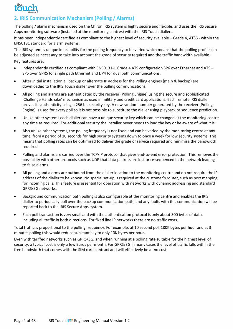
8. Main menu
The IRIS Touch dialler has a number of options under the main menu and below we will go through each section explaining their functions and uses.
Installation Wizard 8.1.
The Installation wizard guides you through the set up process for the IRIS Touch dialler and if there is a problem you will be told what it is and will not be allowed to continue until it is solved.
Note: During the Installation Wizard process you may find that some configurations are already setup, when the panel is using an integrated serial / RS485 connection. These configurations would have been downloaded from the alarm panel setup and if these are incorrect you would need to correct them first in the alarm panel.
Select the Installation Wizard and follow the on screen prompts.
Select interfaces
The first options within the Installation wizard are the network paths settings.
The IRIS Touch dialler has Ethernet and GPRS/3G options for single or dual communications. If you connect a PSTN expansion board you will have an additional communication path and can then have a triple path communicator.
Select the paths required and then click ‘Continue’.
Additional options
The next screen will give you a number of options to enable or disable. Please look at the reference below for more details:
Monitor Dial Port
Sets the IRIS Touch unit to monitor the dial port using the 18K resistor (as supplied in box) being fitted across the A & B terminal of the 2-wire analogue interface (telecoms module), and reports any status change back to the monitoring centre (ARC).
This resistor enables the dialler to detect cable faults and/or tampers and must be fitted at the alarm panel end of the cable to function correctly, the monitoring centre will also need to enable the dial port monitoring from the IRIS Secure Apps software to receive alarm notifications on this status.
Alarm Override
Allows the IRIS dialler to override / replace the phone number and account number used by the alarm panel dialler with the IP address of the monitoring centre and account number entered during configuration. This can be used for dial port or serial / RS485 connection to alarm panels where you may not have access or are unable to change the account / phone number in the alarm panel. This can be useful when converting some old alarm panel sites to work with the IRIS Touch dialler solution.
Monitor Serial
Set the IRIS dialler to monitor the serial port for activity and report any status change back to the monitoring centre (ARC), the monitoring centre will also need to enable the serial port monitoring from the IRIS Secure Apps software to receive alarm notifications on this status.
Roaming SIM
This option enables an enhanced roaming feature when used with a Roaming SIM. Standard Roaming SIMs will always attach to the preferred provider even if this has the weakest signal. Enabling this option forces the GPRS/3G attachment to attach to the strongest signal base station. This allows the IRIS Touch dialler to be even more resilient with the GPRS/3G network.

IRIS Touch Engineering Manual Version 1.2 Page 17 of 48
Account Name/Number
Now you are asked to enter the account (name / number) reference allocated by the monitoring centre which can be alphanumerical and up to 32 characters long, but normally you would expect a 4 or 6 digit numerical account number.
Press the ‘Set’ button and enter in the account name/number and then click the ‘Save’ button. Now confirm that the account is entered correctly and press ‘Continue’.
ARC IP Address
Next you will be asked to enter in the ARC (Alarm Receiving Centre) IP address for the monitoring centre. This can be obtained from the monitoring centre and would normally be the external IP address for their IRIS Secure Apps system.
Press the ‘Set’ button and enter in the ARC IP address and then click the ‘Save’ button. Now confirm that the IP address is entered correctly and press ‘Continue’.
Note: Only the primary/main ARC IP address needs be entered on the dialler as all backup or alternative IP addresses, for the ARC are downloaded to the IRIS Touch dialler on the first polling communications.
Ethernet (IRIS Touch 420NG or 440NG)
Checking Ethernet
The IRIS Touch dialler will now confirm if an Ethernet connection has been made to another piece of Ethernet equipment like a router or switch, if no connection is being seen this will display as ‘Ethernet Disconnected’ and the cable between the 2 pieces of equipment will need to be checked.
If the connection is good you will see ‘Ethernet Connected’ and can press ‘Continue’.
Dialler IP Address
Now you are asked to setup the Dialler IP address for the network to which you are connecting the IRIS Touch dialler.
By default the IRIS Touch dialler is set for DHCP (Dynamic Host Configuration Protocol) which means that the network will allocate an IP address and other related settings gateway and subnet. If you are using a DHCP network connection then press ‘Continue’.
If the customer has requested that a fixed IP address is assigned then press ‘Change’.
You will need to tick the fixed box at the top right and then enter the IP address, subnet mask and gateway information for the customer network.
Once entered press ‘back’ and confirm the information has been entered correctly then press ‘Continue’.
The IRIS Touch dialler will then perform a quick check on the validity of the IP address and confirm if this is ok. If not then please check the IP information entered.

Page 18 of 48 IRIS Touch Engineering Manual Version 1.2
Checking Software Version
Note: If using an IRIS Touch 400NG or 440NG with GPRS/3G and no Ethernet selected then this check will be done after the GPRS/3G settings.
The IRIS Touch dialler will now check with Chiron’s global reflash server to see if a new version is available. If it is you will be presented with the option to ‘Reflash now’.
The Reflasher option has a separate password to the Installation password and if this is the default ‘111111’ you will be requested to change this password as required for EN50136-2.
Note: If there is a newer version available we recommend reflashing the IRIS Touch dialler to the latest version before completing the installation.
The IRIS Touch dialler will now perform various tests depending on which communication paths have been selected.
Ethernet Tests
Next the dialler will send a test poll and alarm message to the monitoring centre to check the Ethernet connection.
Please ensure that both of these are successful and if not the dialler will indicate the possible issues and the configuration to check as shown below:
Note: The normal sequence of sending test alarms from the alarm panel must still be carried out.
This indicates that the poll call did not reach the IRIS Secure Apps system and could be caused by one of the following:
Check that the ARC IP Address entered is correct for the monitor centre.
Check the LAN IP address setup for the IRIS Touch dialler, and confirm with the customer IT department that you have the correct addresses for their network.
Ensure that the alarm and polling port is not being blocked outbound by the customer’s firewall. The required ports are 53165 TCP.
This indicates that the test poll call has reached the IRIS Secure Apps system but the account number is not valid.
Check that the account number is programmed correctly.
Check with the monitoring centre that the account in IRIS Secure Apps is setup.
This indicates that the test poll call has reached the IRIS Secure Apps system but the security keys do not match.
The security key is a feature designed to prevent substitution attacks against both dialler and monitoring centre. When enabled a randomly generated 32 byte key is transmitted to the dialler. This key must be used for all future polling authentication. Both the dialler and the Polling Engine authenticate each other, thus ensuring that a replacement dialler cannot be used to fool a Polling Engine into thinking its status is unaffected during malicious tampering; it also ensures that the dialler will be aware if its IP traffic has been maliciously redirected to a different IRIS Polling Engine.
If the installer has recently replace or defaulted the IRIS Touch dialler then the IRIS Secure Apps operator will need to re-load the security key into the IRIS Touch dialler using the Allocator App.
After checking each of the configuration options the IRIS Touch dialler will then reattempt to test the connection.

IRIS Touch Engineering Manual Version 1.2 Page 19 of 48
GPRS/3G (IRIS Touch 400NG or 440NG)
If you selected connection via GPRS/3G, the dialler will display the current operator / signal strength for the base station to which it is currently attached.
Note: You will require a signal strength of 10 CSQ or higher for a reliable connection. Click Continue.
Next the unit will check if it has GSM/3G registration and if it does it will report GSM/3G registerted. If this screen shows GSM/3G not registered then please check the SIM card is inserted correctly and contact the SIM provider to confirm it is enabled.
All GPRS/3G networks require the Access Point Name (APN) to be set. A few also require User Name (USR) and Password (PWD).
Now enter in the information you have from the SIM provider for this SIM card by clicking ‘Change’.
This will result in the following menu which allows you to enter in the settings for APN, User Name, Password and Pin (Scroll down) with which you may have been supplied.
Once you have confirmed that the information entered in is correct click ‘Continue’.
The IRIS Touch dialler will make a test poll and test alarm transmission over GPRS/3G.
Note: The normal sequence of sending test alarms from the alarm panel must still be carried out.
Please ensure that both of these transmissions are successful. If not successful the dialler will indicate the possible issues and the configuration to check as shown below:
This indicates that the poll call did not reach the IRIS Secure Apps system and could be caused by one of the following:
Check ARC IP Address entered is correct for the monitor centre.
Note: if using Ethernet on a VPN for example then the ARC IP would be for this connection and not the correct one for GPRS/3G. In this case please have the ARC operator check the Allocator setup for this account and try a Reload Parameters.
Check GPRS/3G settings are correct for APN, User name, Password and Pin.
Ensure SIM card is setup for GPRS/3G Machine to Machine data.
This indicates that the test poll call has reached the IRIS Secure Apps system but the account number is not valid.
Check that the account number is programmed correctly.
Check with the monitoring centre that the account in IRIS Secure Apps is setup

Page 20 of 48 IRIS Touch Engineering Manual Version 1.2
This indicates that the test poll call has reached the IRIS Secure Apps system but the security keys do not match.
If the installer has recently replace or defaulted the IRIS Touch dialler then the IRIS Secure Apps operator will need to re-load the security key into the IRIS Touch dialler using the Allocator App.
After checking each of the configuration options the IRIS Touch dialler will then reattempt to test the connection.
PSTN (IRIS Touch 4xxNG with PSTN Expansion Board)
The IRIS Touch dialler will now check the PSTN connection if the PSTN expansion board has been fitted and PSTN network path selected. If the Line voltage is detected this will indicate connected and you can continue, if it indicates PSTN disconnected please check the cable and connection to the PSTN line. This can take upto 30 seconds to detect after Powering up.
Pin Alarms
Now you have the option to use pin alarms which are the IRIS Touch pin inputs which can be used for SMS messaging or alarm signalling.
Select ‘Yes’ if you want to use the pin alarms or ‘no’ to continue.
PSTN Alarm Setup (Only if you have selected PSTN)
If you have selected the PSTN interface you will now have the option to setup the main and backup PSTN line receiver numbers. These would be the PSTN telephone numbers for the standard PSTN line receivers at the monitoring centre (SurGard / Radionics for example), that you would send alarms to via a PSTN line connected directly to an alarm panel.
Select ‘Change’ and then selected and enter the main and backup PSTN numbers and then click ‘back’ and confirm these are entered correctly. Click ‘Continue’
Note: If you are going to use SMS as the Pin alarm format leave these blank.
Pin Format
You will now be asked to select which pin alarm format you wish to use.
Note: SMS only available on IRIS Touch 400NG & 440NG diallers. If you select PSTN network interface (EXT2 Expansion Board fitted) then the option for SIA will not be available as currently this is not available over PSTN.
Select the format you wish to use and press ‘Continue’.
You will be presented with a warning that all current pin input settings will be lost, click “Continue” and then click “Continue” again.
For more information on each format and additional configurations for the Pin alarms please go to the Section 8.2 “Settings – Pin Inputs”.
Pins Required
You will now be asked to select the pins you wish to enable and use if you have selected SIA, FF or CID for the alarm format.
The number of pins available will depend if one of the expansion boards has been fitted.
Unselect pins you wish to disable from sending alarms and leave ticked only the pins you want to use for alarm transmission, and then click ‘Continue’.

IRIS Touch Engineering Manual Version 1.2 Page 21 of 48
Monitor for tampers
You will now be asked if you want to monitor for tamper on the pin alarm inputs, which is done using the sense resistors as detailed in Section 7.6 “Pin Inputs”.
Select ‘Yes’ or ‘No’ depending if you want to use this function.
Setup Complete
The Initial setup is now complete. Click ‘Finish’ to exit the Installation Wizard and return back to the main menu.
For advanced settings select the ‘Settings’ menu.
Once you have completed the Installation Wizard and setup any additional panel interface configuration via the settings menu you will need to check / configure the panel for the connection method being used if not already configured.
Settings 8.2.
The Settings option is used to configure additional settings required for installation or additional options that may be added at a later date. Below is a detailed description of all of these options.
Network Interfaces
This section allows the user to select the communication paths to be used for polling / alarms on a multipath IRIS Touch dialler. There are up to 3 options as detailed below, depending on which version of IRIS Touch dialler:
Ethernet
GPRS/3G (Machine to machine data ‘M2M’)
PSTN (PSTN Expansion Board required)
Account Name/Number
Set the account name/number for the IRIS Touch unit on site, as allocated by the monitoring centre.
ARC IP Address
Set up the external IP address for the monitoring centre receiver (polling engine).
Note: Only the primary/main ARC IP address needs be entered on the dialler as all backup or alternative IP addresses, for the ARC are downloaded to the IRIS Touch dialler on the first polling communications.
Dialler IP Address (IRIS Touch 420NG or 440NG)
Allows the user to setup the IP address of the dialler to either automatic (DHCP) or a fixed IP address. The settings below will either show the IP address received (DHCP mode) or, if fixed, allow the user to set the IP address, subnet and gateway:
IP Address
Subnet Mask
Gateway
Mac Address (view only)

Page 22 of 48 IRIS Touch Engineering Manual Version 1.2
GPRS/3G Settings (IRIS Touch 400NG or 440NG)
This section allows the user to enter or view the GPRS/3G settings.
Signal Strength
This option shows the provider and signal strength for the base station to which the dialler is connected.
Run Network Scan
Performs a network scan for all providers in the local area, and gives a chart of the best 3 base stations per provider.
To perform this the dialler should be powered down and the SIM card removed.
For the chosen GPRS/3G SIM provider CSQ values with a minimum of 10 (ideally 12) are required for at least 2 of the 3 base stations for reliability.
APN
GPRS/3G Access Point Name for the SIM card used.
User Name
If none required then leave blank otherwise set the GPRS/3G user name for the SIM card.
Password
If none required then leave blank otherwise set the GPRS/3G password for the SIM card.
SIM PIN
If the SIM card used has a PIN number set please enter here, normally this is disabled/blank.
Call Barring
Incoming calls can be rejected to helps prevent any possibility of blocking the GSM/GPRS/3G communication paths.
Roaming SIM
This option enables an enhanced roaming feature when used with a roaming SIM.
A standard roaming SIM will always attach to the preferred provider even if this has the weakest signal.
Enabling this option forces the GPRS/3G attachment to connect to the strongest signal identified by the IRIS dialler. This allows the IRIS Touch dialler to be even more resilient with the GPRS/3G networks when using roaming SIM.

IRIS Touch Engineering Manual Version 1.2 Page 23 of 48
Panel Interface
The IRIS Touch dialler has a number of panel interface options that allow connection too many different systems. Below are the settings available for each connection type and their function:
Dial Port
Monitor Cable
Sets the IRIS Touch dialler to monitor the dial port using the 18K resistor (as supplied in box) fitted across the A & B terminals of the 2-wire analogue interface (telecoms module). Reports any status changes back to the monitoring centre (ARC).
This resistor enables the dialler to detect cable faults and/or tampers and must be fitted at the alarm panel end of the cable to function correctly. The monitoring centre will also need to enable the dial port monitoring from the IRIS Secure Apps software to receive alarm notifications on this status.
Report Poll Fail
Tick to enable the dialler to drop the line voltage on the dial port connection if unable to poll over any configured path to the monitoring centre. This allows the panel to detect and report locally on the keypad of the alarm panel that it has a line fault, so the site has local indication of a communication failure (for EN standards).
Enable Ringtone
This feature is to allow the user to enable or disable the IRIS unit simulating the PSTN ring tone to the dial port while the connection is being made. In most case this can be left as the default setting but if you are having issues with alarms or remote service app connection (Upload/download), then you can try turning this off.
Ring
If the alarm panel is expecting European or UK ring cadence to detect an incoming call, you can change the IRIS Touch dialler to simulate either from Euro ‘ticked’ to UK ‘unticked’ (controls ring and ring tone cadence).
Only Analogue
Forces alarm calls from the panel telecoms module to the IRIS dial port to go over the GSM/3G or PSTN communication paths. This is done by using the number dialed by the panel telecoms module.

Page 24 of 48 IRIS Touch Engineering Manual Version 1.2
Serial Port Com (Serial TTL connection)
Monitor Cable
Set the IRIS dialler to monitor the serial port for activity and report any status change back to the monitoring centre (ARC). The monitoring centre will also need to enable the serial port monitoring from the IRIS Secure Apps software to receive alarm notifications on this status.
Report Poll Fail
Set the IRIS dialler to stop responding to the serial commands if polling has failed. This will then indicate the failure back to the alarm panel. This allows the site to have local indication of a communication failure (for EN standards).
Emulation Mode
This allows you to setup the serial port for Normal, Cooper I-ON or Texecom Premier Connections, by default this is setup for Texecom emulation. For more information on the connection and setup please refer to the panel installation manual available from http://www.chironsc.com/downloads_security.html.
Note: For the Cooper I-ON panel you will need to purchase separately the IRIS CT-interface board. Please contact the Sales team for further information on this.
Serial Port RS232_1
Monitor Cable Set the IRIS dialler to monitor the serial port for activity and report any status change back to the monitoring centre (ARC).The monitoring centre will also need to enable the serial port monitoring from the IRIS Secure Apps software to receive alarm notifications on this status.
Report Poll Fail Set the IRIS dialler to stop responding to the serial commands if polling has failed. This will then indicate the failure back to the alarm panel. This allows the site to have local indication of a communication failure (for EN standards).
Configuration
Allows you to enable Normal (basic), Full, DTE or DCE interface mode for Serial port RS232_1.
Note: enabling Full, DTE or DCE modes will disable serial Port RS232_2.
Normal Sets the serial port RS232_1 to basic mode which only uses the TX1, RX1 and 0V screw terminals
Full DCE The Serial Port RS232_1 will now be in full RS232 mode (all control signals) using the DCE header. Please contact the sales team for the relevant cable requirements.
Full DTE The Serial Port RS232_1 will now be in full RS232 mode (all control signals) using the DTE header. Please contact the sales team for the relevant cable requirements.

IRIS Touch Engineering Manual Version 1.2 Page 25 of 48
Serial Port RS232 2
This is the configuration setting for the second RS232 serial port connections (TX2 & RX2) and allows the following configurations.
Monitor Cable
Set the IRIS dialler to monitor the serial port for activity and report any status change back to the monitoring centre (ARC). The monitoring centre will also need to enable the serial port monitoring from the IRIS Secure Apps software to receive alarm notifications on this status.
Report Poll Fail
Set the IRIS dialler to stop responding to the serial commands if polling has failed. This will then indicate the failure back to the alarm panel. This allows the site to have local indication of a communication failure (for EN standards).
Emulation Mode
This allows you to setup the serial port RS232 port for Normal, DSC SN4441, Espa, HHL and HHL plus connection for alarm communications. Please refer to the IRIS Touch panel installation manual for further details. For more information on the connection and setup please refer to the panel installation manual available from http://www.chironsc.com/downloads_security.html.
Serial Port RS485
Galaxy
Set the RS485 bus for Honeywell Galaxy mode where the IRIS Touch will simulate one of 3 external modules in the following order (Ethernet, External Telecoms, and External RS232).
ProSYS
Set the RS485 bus for the Risco ProSYS bus to allow Upload/Download connections but not alarms, the panel alarm will need to be either on the dial port, or pin inputs.
Galaxy
The Galaxy Bus emulation mode has some additional option available for configuration and these are detailed below:
System ID
Can override or enter a system ID independent from the panel.
Emulation Mode
This option allows you to select the Honeywell Galaxy RS485 bus module that is emulated to the Galaxy control panel. By default this is set to AUTO (Automatic assigned) which will try the external Ethernet module first and if this is not seen then the external PSTN, and finally the external serial modules. This allows for backwards compatibility to older Galaxy panel software versions that do not support the Honeywell Ethernet module (Galaxy Classic below version 4.00).
You can also pre fix the module emulated to be either Ethernet or PSTN if required; this may be needed if for instance you already have a Honeywell Ethernet module fitted.

Page 26 of 48 IRIS Touch Engineering Manual Version 1.2
Alarm Override
Allows the IRIS unit to override the alarm panels account number and dialled number with those set in the IRIS Touch dialler.
Extra Features
The extra features built into the IRIS Touch allow the user to set up the options for Set/Unset inputs for alarm signalling, EN54-21 fire mode, VdS modes and ILKA specific functions.
The IRIS Touch can be set to operate to conform to VdS 2463, and allow one of two settings to be selected VdS Intruder or VdS Fire as shown below:
Normal
Default mode for the IRIS Touch (pins and relays set to normal functions).
Set / Unset
In a normal alarm installation the IRIS diallers are used in conjunction with an attached alarm panel. However, if the requirements for monitoring are simple, requiring only a few alarm events like set & unset or entry / exit alarms (e.g. ATM monitoring), the IRIS Touch dialler can be setup to be a simple alarm panel using the pin inputs.
Set / Unset Pin
Configuration options for the Set/Unset pin.
Pin Number
Allocate which pin is for the set and unset signals.
Trigger Mode
Set the trigger mode to ‘normal’, the unit is unset when the input pin is open circuit. This method is suitable for an external physical switch such as a key-switch.
Alternatively set the trigger mode to ‘pulse’, a pulse on the set/unset input toggles the set/unset status. This is suitable for an external device such as a proximity tag reader.
Exit Delay
Setup the exit delay timer which at default is 10 seconds.
Entry Pin
Allocate which pin is to be used for the entry signal.
Entry Delay
Setup the entry delay timer which at default is 10 seconds.
Set Status Relay
Allocate which relay output is used as the set/unset status indicator and the default state (default is normally open).

IRIS Touch Engineering Manual Version 1.2 Page 27 of 48
Alarm Status Relay
Enable relay D as the alarm status indicator which if any pin Inputs (enabled) are in an alarm state will change state depending what the default state is set to (default is normally open).
EN54-21 Fire
Set the IRIS Touch to EN54-21 Fire conformances for further details see Section 11 “Installation for EN54-21 Compliant Fire Applications”.
VDS Intruder
Set the IRIS Touch to VdS Intruder conformance and this will preset pin inputs and relay functions. See Section 10 “Installation for VdS 2463 Compliance” for further details.
VDS Fire
Set the IRIS Touch to VdS Fire conformance and this will preset pin inputs and relay functions. See Section 10 “Installation for VdS 2463 Compliance” for further details.
ILKA with PSU
Customer specific PSU monitoring with predefined Threshold and Dial port phone settings.
ILKA without PSU
Customer specific mains monitoring with predefined Threshold and Dial port phone settings.
Tamper input
Enable or disable the tamper input on the IRIS Touch dialler which allows you to connect an external tamper.
Incoming IP Addrs
As a security feature allows the user to define a list of 3 source IP addresses that are allowed to connect to the IRIS serial port. If all addresses are left blank then all calls are allowed.

Page 28 of 48 IRIS Touch Engineering Manual Version 1.2
Pin Inputs
Setup the Inputs (Pins) function between SMS messaging, SIA Alarm format, Fast format or Contact ID alarm format.
Note: You are able to select one alarm format for the Pins (SIA, FF or CID) and then setup individual pins to be SMS messaging if required.
When changing the pin format between one of the alarm formats (SIA, FF or CID) you will receive a warning message indicating that all pins will be setup for this alarm format and returned to the default allocation shown below, as pins cannot be setup to different alarm formats.
SMS (IRIS Touch 400NG or 440NG)
On input ‘Set’ (open circuit) and input ‘Restore’ (close circuit) the IRIS Touch will send the configured SMS message for the ‘Set’ or ‘Restore’ text, to the configured phone number.
Selecting SMS for the input format will display the following options to configure for each pin as shown.
Monitor Cable
The option to monitor the input for tamper will also be given. See Section 7.6 “Pin Inputs”.
Enable
Enable/disable each pin input with the ‘Enable’ tick box.
Inverse
The function of the inputs ‘Set’ and ‘Restore’ can also be inverted to be the opposite way round by ticking the ‘Inverse’ tick box. This will mean that the ‘Set’ is now the closed circuit and the ‘Restore’ is open circuit.
Phone no
Phone number used to send the SMS messages.
Set msg / Restore msg
Setup the ‘Set’ and ‘Restore’ messages to be sent to the entered phone number. The maximum length for the text message is 24 characters.

IRIS Touch Engineering Manual Version 1.2 Page 29 of 48
SIA
Selecting SIA for the Inputs means that the inputs will send specific SIA alarm protocol messages on the set event and restore for that input, the options available as shown.
SMS
One input can be setup to be SMS by ticking the ‘Set as SMS’ and this will allow setup of the SMS option as shown above.
Monitor Cable
You also have the option to monitor the input for tamper which is detailed in Section 7.6 “Pin Inputs”.
Enable
Enable/disable each pin input with the ‘Enable’ tick box.
Inverse Polarity
The function of the inputs ‘Set event’ and ‘Restore event’ can be inverted to be the opposite way round by ticking the ‘Inverse’ tick box. This will mean that the ‘Set event’ is now the closed circuit and the ‘Restore event’ is open circuit.
Set msg / Restore msg
Setup the ‘Set / Restore’ message sent on the relevant event using the correct format as defined in SIA Format protocol SIA DC-03-1990.01(R2003.10). At default this is pre-set to a specific SIA code and a zone number (see table below). This can be modified for any event code and a text description added for each event which will be sent with the SIA alarm code as with SIA level 3 alarm protocols. These can be no longer than 15 characters in total.
To add a text description to the Set / Restore msg use the following format applying ^ before and after to indicate the text description:
Set msg SIA code Set msg text description Entry into the Set msg via the Touch screen
NFA01 FIRE NFA01^FIRE^
Default SIA Set/Restore event codes for Pin inputs:
Pin Number
Set message
SIA code
Restore message
SIA code SIA event Description
1 NFA01 NFR01 Fire alarm zone 1
2 NPA02 NPR02 Panic alarm zone 2
3 NBA03 NBR03 Burglary alarm zone 3
4 NOP04 NCL04 Open/Close zone 4
5 NIA05 NIR05 Equipment fault zone 5
6 NBB06 NBU06 Burglary bypass zone 6
7 NBV07 NBR07 Burglary verified zone 7
8 NTA08 NTR08 Tamper alarm zone 8
9 NAT09 NAR09 AC Power trouble zone 9
10 NFT10 NFJ10 Fire trouble zone 10
11 NQA11 NQR11 Emergency alarm zone 11
12 NYT12 NYR12 System battery trouble zone 12
13 NMA13 NMR13 Medical alarm zone 13
14 NUA14 NUR14 Untyped alarm zone 14
15 NUA15 NUR15 Untyped alarm zone 15
16 NUA16 NUR16 Untyped alarm zone 16

Page 30 of 48 IRIS Touch Engineering Manual Version 1.2
FF (Fast Format)
Selecting FF for the Inputs means that the inputs will send a specific Scancom fast format alarm protocol messages on the event and restore for that input, the options available are shown below:
SMS
One input can be setup to be SMS by ticking the ‘Set as SMS’ and this will allow setup of the SMS option as shown above.
Monitor Cable
There is also the option to monitor the input for tamper which is detailed in Section 7.6 “Pin Inputs”.
Enable
Enable/disable each pin input with the ‘Enable’ tick box.
Alarm
Sets the input to be an alarm triggered input which will send the following states of the channel according to the following:
Signal Event Type Description
5 Not in alarm The alarm triggering input is at its quiescent state.
1 New alarm The alarm triggering input is at its active state and it has not previously been reported.
6 In alarm The alarm triggering input is at its active state and it has previously been reported.
3 New restore The alarm triggering input has just returned to its quiescent state from the alarm state.
O/C (open / close)
Sets the input to be an open/close input which will send the following states of the channel according to the following:
Signal Event Type Description
2 New opening The alarm triggering input is at its alarm state, the intruder alarm system has been unset.
4 New closing The alarm triggering input is at its quiescent state, the intruder alarm system has been set.
5 Premises closed The alarm triggering input is at its quiescent state and it has previously been reported.
6 Premises open The alarm triggering input is at its alarm state and it has previously been reported.
Inverse Polarity
The function of the inputs ‘Event’ and ‘Restore’ can be inverted to be the opposite way round by ticking the ‘Inverse’ tick box. This will mean that the ‘Event’ is now the closed circuit and the ‘Restore’ event is open circuit.

IRIS Touch Engineering Manual Version 1.2 Page 31 of 48
CID (Contact ID)
Selecting CID for the inputs means that the inputs will send a specific Ademco® alarm protocol messages which will include an event code, zone and group number, on the event and restore for that input. The following options available are shown below:
SMS
One input can be setup to be SMS by ticking the ‘Set as SMS’ and this will allow setup of the SMS option as shown above.
Monitor Cable
There is also the option to monitor the input for tamper which is detailed in Section 7.6 “Pin Inputs”.
Enable
Enable/disable each pin input with the ‘Enable’ tick box.
Inverse Polarity
The function of the inputs ‘Event’ and ‘Restore’ can be inverted to be the opposite way round by ticking the ‘Inverse’ tick box. This will mean that the ‘Event’ is now the closed circuit and the ‘Restore’ event is open circuit.
Event
Enter the Event code (3 digits 0-9) for this input for example: 110 = Fire.
To determine which event code is to be used please refer to the Digital Communication Standard -
Ademco® Contact ID Protocol - for Alarm System Communications SIA DC-05-1999.09
Group
Group or Partition number (2 digits 0-9).
Use 00 to indicate that no specific group or partition information applies.
Zone Zone number (Event reports) or User # (Open / Close reports) (3 digits 0-9).
Use 000 to indicate that no specific zone or user information applies.
Default CID Set/Restore event codes for Pin inputs:
Pin Number
Contact ID event code
Group number
Zone number
Contact ID event description
1 110 00 001 Fire alarm zone 1
2 120 00 002 Panic alarm zone 2
3 130 00 003 Burglary alarm zone 3
4 400 00 004 Open/Close zone 4
5 300 00 005 System Trouble zone 5
6 573 00 006 Burglary bypass zone 6
7 139 00 007 Intrusion verifier zone 7
8 137 00 008 Tamper alarm zone 8
9 301 00 009 AC Power trouble zone 9
10 380 00 010 Sensor trouble zone 10
11 101 00 011 Personal emergency alarm zone 11
12 302 00 012 Low system battery zone 12
13 100 00 013 Medical alarm zone 13
14 323 00 014 Alarm relay zone 14
15 323 00 015 Alarm relay zone 15
16 323 00 016 Alarm relay zone 16

Page 32 of 48 IRIS Touch Engineering Manual Version 1.2
Trouble Reporting
Trouble reporting allows setup of the reporting of communication faults via relays or SMS and making diagnostic calls over an IP communication path (Ethernet or 3G/GPRS).
The remote diagnostic call allows an outbound TCP/IP call using TCP/IP port number 51292 to a senior technician with a PC/laptop running the IRIS Toolbox software. This will then allow them to check setup and run diagnostics remotely to investigate any issues.
Below is a breakdown of these individual setup options:
Via Relays
It is possible to enable or disable the IRIS Touch dialler toggling the state of the relays to indicate communication path failures. This is intended to signal failures back to the panel inputs so the site has local indication of a communication failure (for EN standards). The IRIS Touch dialler allows the selection of which relay is to be used for the poll fail indication or communication path fail.
If you click on the box you can toggle through which relay you wish to assign for this fault report and note the same relay can be used for multiple path fault indication.
The option for ‘Fault’ reporting allows reporting of system fault indications via the selected relay, for a list of these faults please check the Section 9 “Trouble Reporting”.
Via SMS
The IRIS Touch dialler can send SMS messages to indicate communication / line faults via the GSM/3G network.
There are 4 SMS phone number that can be set up for sending SMS messages, for line fail/restore reporting.
Diag Call IP addr
This menu allows the IP address of the PC/laptop running the IRIS Toolbox software to be entered in order to make an outbound TCP/IP diagnostics call for remote diagnostics.
Diagnostic Call
This option allows you to make a diagnostics call back to the IP address entered above for remote diagnostics to the IRIS Toolbox software.
On first entry this will show the one time password for this remote connection which may need to be passed on to the operator of the IRIS Toolbox software.
Press the ‘Diagnostic Call’ button once the password has been passed onto the operator and they are ready to receive the call.

IRIS Touch Engineering Manual Version 1.2 Page 33 of 48
Relay SMS activation (IRIS Touch 400NG or 440NG)
The IRIS Touch dialler allows each relay to be activated or deactivated by a predefined SMS message from a mobile phone.
Phone no
Sets which calling device (mobile phone) is allowed to control the relay with the relevant SMS message. This is done by using the Calling line number (CLI) on the SMS and comparing this with the number entered.
The dialler will start the comparison from the least significant digit and then work backwards as shown below:
For the example we will use the phone number 07890123456, please confirm what CLI number is being received by using you mobile phone to receive the call, this will allow you to see the incoming CLI number.
0 7 8 9 0 1 2 3 4 5 6
Starting from the LSB ‘6’ you can work backwards to compare the CLI number so for example you can enter a number of 56. This will allow all phone numbers with a CLI ending in 56.
Leaving the source number blank will allow any mobile number to set or restore the relay as long as the SMS text matches.
Activation msg Sets the SMS text message required to open the relay, note this is case sensitive. Deactivation msg Sets the SMS text message required to close the relay, note this is case sensitive.
PSTN Settings (IRIS Touch 4xxNG with the PSTN Expansion Board)
The IRIS Touch 4xxNG with the PSTN Expansion Board has some additional settings available for configuration these are detailed below:
PSTN Alarm Setup
The IRIS Touch Pin Alarms can signal over the PSTN line to a standard PSTN main and backup alarm receiver which would be configured here. Enter in the main and backup PSTN telephone numbers for each of these receivers.
PSTN Test Alarm
This option allows the engineer to setup the periodic time that the IRIS Touch dialler will send a Contact ID PSTN test alarm to main and then backup setup in the PSTN Alarm Setup.
Audio
The PSTN connection on the IRIS Touch Expansion Board can have its audio volume output increased via this setting. At default this is set to low and can be changed to high if you are seeing issues with alarm communication over PSTN.
Tone Detect
You can change the tone detection on the IRIS Touch PSTN line interface from the default ‘High’ to ‘Low’ if having issues with and PSTN alarms or polling.
LSB
Page 34 of 48 IRIS Touch Engineering Manual Version 1.2
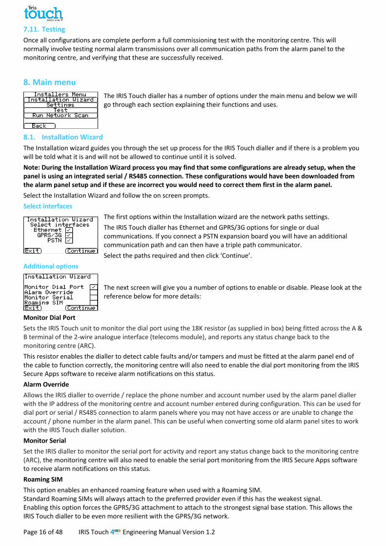
Language
The IRIS Touch dialler supports a number of languages that you can select here.
Installers Password
When the user first accesses the Installer menu, the Installers password is required, which is defaulted to ‘111111’. During installation you will be required to change the password as required for EN50136-2. This password can be changed again if required with this setting and you will be asked to enter and then confirm the new password.
Contrast
This setting allows you to alter the contrast on the Touch screen.
Default All
Completely resets the IRIS Touch dialler to manufacturing defaults.
Build Information
IRIS Touch software version, GPRS/3G software version and dialler serial number are displayed.

IRIS Touch Engineering Manual Version 1.2 Page 35 of 48
Reflash
The option will be given to reflash the unit to the latest version available from the Chiron reflash server.
On first entry to the reflash option, which could be during installation or maintenance, the password will need to be changed as required for EN50136-2.
Otherwise you will be asked to enter the reflash password that has been configured for this unit.
A reflash to update the IRIS Touch dialler to the latest software version can be initiated and the options are shown below:
Reflash Password
This password can be changed again if required with this setting.
Reflash IP Address
The default reflash IP address is the Chiron reflash server setup on an IP address 195.59.117.164 which is available 24/7 for connections, and kept up to date with the latest software available.
There are cases where a customer will only open their network to communicate back to the monitoring centre (network/IP address), and in some cases the monitoring centre has their own reflash server installed. This option allows the sending of a reflash request to an alternate IP address.
Reflash Now
Initiate the reflash to the reflash IP address and will bring up a status window to indicate progress.
Test 8.3.
The test menu allows checking of all current enabled communication paths, and will test both polling and alarms. There are two options here and these are detailed below:
Test
This will start the polling and alarm tests over the enabled communication path or paths.
Once the tests are complete the following possible outcomes are available as shown in the table on the next page.
Start GPRS/3G Fault Test (IRIS Touch 200NG or 240NG)
This option enables an engineer to simulate a GPRS/3G fault so the monitoring centre can check that the report is presented properly to the operators.
Note: This mode stays operational for 1 minute and is then automatically switched off, to prevent a situation where the installer forgets to switch it off thereby disabling GPRS. It can be switched off earlier if required.

Page 36 of 48 IRIS Touch Engineering Manual Version 1.2
Testing Results and explanations
Checking Ethernet
Connected: Confirms the dialler is connected to the Ethernet network.
Not Connected: The dialler is currently not connected to the Ethernet network; check the Ethernet cable and cabling all the way through to the other end (Router / Switch).
Checking IP address
The IRIS Touch dialler will check the dialler IP address is valid as set either by DHCP or manually.
Ethernet test Poll
Successful: Dialler successfully polled to the monitoring centre (ARC) IRIS Secure Apps system over the Ethernet network.
Polling disabled: Configured not to poll over the Ethernet network; check ARC IP address and account number are still entered.
Connection failed: Failed to connect to ARC over the Ethernet network; check the ARC IP address is correct, confirm Ethernet router external WAN connection and firewall setup.
Connection made, poll fail: Connected to the ARC IRIS Secure Apps but was rejected; check correct account number has been setup at ARC IRIS Secure Apps and that correct account number is entered in dialler.
Connection made, authentication failed: Connected to the ARC IRIS Secure Apps but was rejected due to invalid security key; check correct account number entered in dialler. If a replacement dialler was installed the ARC will need to perform a ‘Reload Parameters’ on the IRIS Secure Apps web interface.
Ethernet test alarm
Successful: Ethernet SIA level 3 test alarm reported successfully to ARC.
Connection failed: Failed to send alarm to ARC over Ethernet network; check with ARC.
GSM/3G registration
Registered: Dialler is connected to the GSM/3G network.
Not registered: The dialler is not registered to the GSM/3G network; check SIM card is enabled and inserted correctly into the SIM card holder, also check antenna and signal strength are connected and above minimum signal strength.
Signal strength Indicates current signal strength, which is recommended to be above 10 for reliable communications; if below the minimum required either move the dialler or antenna to gain better coverage or fit an external high gain GPRS/3G antenna.
GPRS/3G test poll
Successful: Dialler successfully polled to the monitoring centre (ARC) IRIS Secure Apps system over the GPRS/3G network.
Polling disabled: Configured not to poll over GPRS/3G network; check ARC IP address and account number are still entered.
Connection failed: Failed to connect to ARC over GPRS/3G network; check the ARC IP address is correct, and confirm SIM card is enabled for GPRS/3G machine to machine data (M2M) with the SIM card provider.
Connection made, poll fail: Connected to the ARC IRIS Secure Apps but was rejected; check correct account number has been setup at ARC IRIS Secure Apps and that correct account number entered in dialler.
Connection made, authentication failed: Connected to the ARC IRIS Secure Apps but was rejected due to invalid security key; check correct account number entered in dialler, and if a replacement dialler was installed the ARC will need to perform a ‘Reload Parameters’ on the IRIS Secure Apps web interface.
GPRS/3G test alarm
Successful: GPRS/3G SIA level 3 test alarm reported successfully to ARC.
Connection failed: Failed to send alarm to ARC over GPRS/3G network; check with ARC.

IRIS Touch Engineering Manual Version 1.2 Page 37 of 48
Run Network Scan 8.4.
IRIS Touch 400NG or 440NG with GPRS/3G connection:
The GPRS/3G network scan function allows you to get overall feedback of signal strength from all providers in the area. This should be performed on installation as detailed in Section 7 “Installing the IRIS Touch Dialler” and also after installation, for example during maintenance, as location signal stregnth can change e.g. new building in the area or cosmetic changes in the current location (storage racking etc).
The scan must be carried out without the SIM card fitted.
The dialler listens for every base station in range, requests operator name and records the signal strength.
This will take a few minutes to complete.
For a reliable GPRS/3G connection it is recommended that for the chosen network (SIM card) used there should be at least two base stations with signal strength (CSQ) of 10 or more for reliability.
If the signal strength is below or close to minimum then try to reposition the antenna or use an external high gain antenna (if necessary), and rerun the network scan.
Once you have the required GPRS/3G signal strength power down the dialler and insert the SIM card into the SIM card holder, then power the dialler back up.

Page 38 of 48 IRIS Touch Engineering Manual Version 1.2
9. Trouble report
When the SYS LED is flashing yellow the dialler has some trouble events being reported. These can be viewed in more detail by accessing the welcome screen, then ‘Status – Trouble’ and finally ‘View Trouble Report’ option.
The Trouble Report Menu indicates what the current system troubles are and below is an explanation of all possible events.
Trouble Reported Explanation
E-net disconnected The dialler is currently not connected to the Ethernet network; check the Ethernet cable and cabling all the way through to the other end (Router / Switch).
E-net polling fail Unable to poll via the Ethernet network to the monitoring centre’s (ARC) IRIS Secure Apps system; check ARC IP address, confirm Ethernet router external WAN connection and firewall setup.
GSM/3G not registered Not able to register to the GSM/3G network; normally means the SIM card has been disabled, check with SIM provider.
GPRS/3G Polling fail Unable to Poll via the GPRS/3G network to the monitoring centre’s (ARC) IRIS Secure Apps system; check ARC IP address, SIM card is enabled for GPRS/3G machine to machine data (M2M).
SIM Card not fitted SIM card not being seen in the IRIS unit; check SIM fitted and that connection is ok.
SIM PIN required SIM card has been setup for a PIN number and no SIM PIN entered in configuration; Confirm the correct SIM PIN with the SIM provider and enter.
SIM PIN error Current SIM PIN entered in the configuration is invalid; confirm correct SIM PIN with SIM provider and confirm entered correctly.
Poll Failed The dialler is unable to poll over any path; check correct ARC IP address entered, and communication paths setup.
Fault On Dial Port Dial port configured to monitor dial port and sense resistor not being detected (18K). Check cable/resistor connections.
Pin Fault on pin** Indicates that the dialler has been set to monitor for tampers and is in an open or short circuit tamper condition. Check cable/resistors connections.
Serial port fault The dialler is setup to monitor serial but is seeing no activity on the serial connection; check setup of the dialler / panel and physical connection.
Fail to communicate A dialler input has been triggered and this event has failed to be communicated to the ARC. Check all communication paths are working and configuration is correct; also check with the ARC that they have no known issues with received alarms (E.G. IRIS Poll engine IP link down).
Eeprom The dialler has a possible hardware issue and is unable to see the Eeprom. The Eeprom stores all local parameters for protection against power failure.

IRIS Touch Engineering Manual Version 1.2 Page 39 of 48
10. Installation for VdS 2463 Compliance
Introduction 10.1.
Chiron’s IRIS Touch 400NG Alarm over IP diallers have been tested and certified by VdS in Germany to be compliant with the standard VdS2463 ‘Alarm Transmission for alarm signals (ATE)’ and have been allocated a ‘G’ approval number.
The IRIS Touch models are certified to VdS2463 and for which this guide is applicable includes:
IRIS Touch 400NG, Touch 420NG, Touch 440NG
For compliance with this standard, the installer must set the IRIS Touch dialler to operate in one of the following:
VDS Intruder mode
VDS Fire mode Chiron provides a special enclosure and the IRIS Touch dialler must be used with this enclosure and powered from the control and indicating equipment. This additional power consumption has to be taken into account for the standby duration.
Note: if these conditions are not complied with, then the installation will not be compliant with VdS2463.
All other aspects of the installation are covered in the standard intruder alarm installation guide for the particular product.
Installation for VdS2463 compliance 10.2.
For VdS 2463 compliant installations, the IRIS Touch should be used only with the pin inputs. The dial capture (2 wires) interface cannot be used as it is not compatible with the VdS dialler protocols. Chiron provides a special VdS compliant enclosure and wiring kit that should be used. This kit includes: 1. Tamper proof enclosure. 2. Tamper detection switch. 3. Termination blocks and sense resistors for the connection and monitoring of the inputs from the alarm system, 4. An external relay for fire applications. 5. Cable ties for strain relief
The enclosure is supplied pre-configured with tamper switch, mounting points for the IRIS Touch and internal terminal blocks. The IRIS dialler can be set through menu selections to operate in conformance to VdS 2463. One of two modes can be selected – VdS Intruder or VdS Fire.
This can be done via the touch screen Settings > Extra Features menu, as shown below.
Enter the installer’s menu on the Touch display and use the wizard to configure the dialler’s basic configuration and polling in the normal way. Enable tamper detection on all used input pins, except pin 1. This sets up the inputs so that the end of line resistor supervision (see diagrams below) is monitored. With the Settings menu, scroll to “Extra Features” menu. Tick the VDS Fire or VDS Intruder option as required. With the Setting menu, scroll to “Input Pins” menu. Enter appropriate messages and configurations for the used pins. Disable the unused pins. Please note that for conformance to the VdS standard, shielded cables should not be used for interconnection with the Intruder Alarm System Alarm Control and Indicating Equipment (IAS-CIE).
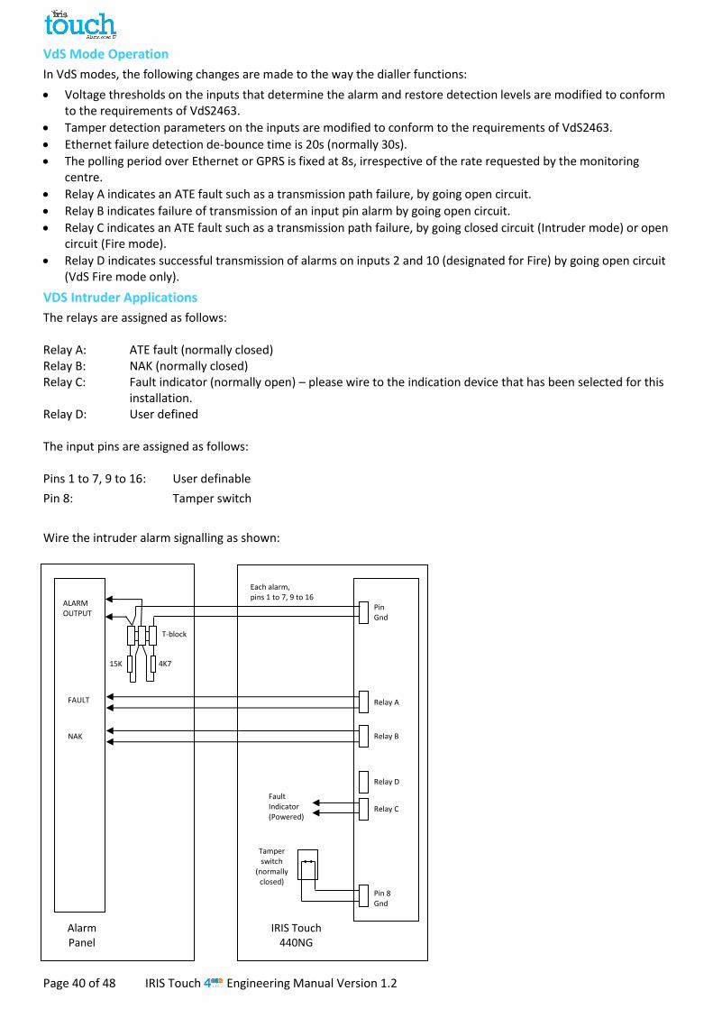
Page 40 of 48 IRIS Touch Engineering Manual Version 1.2
VdS Mode Operation
In VdS modes, the following changes are made to the way the dialler functions:
Voltage thresholds on the inputs that determine the alarm and restore detection levels are modified to conform to the requirements of VdS2463.
Tamper detection parameters on the inputs are modified to conform to the requirements of VdS2463.
Ethernet failure detection de-bounce time is 20s (normally 30s).
The polling period over Ethernet or GPRS is fixed at 8s, irrespective of the rate requested by the monitoring centre.
Relay A indicates an ATE fault such as a transmission path failure, by going open circuit.
Relay B indicates failure of transmission of an input pin alarm by going open circuit.
Relay C indicates an ATE fault such as a transmission path failure, by going closed circuit (Intruder mode) or open circuit (Fire mode).
Relay D indicates successful transmission of alarms on inputs 2 and 10 (designated for Fire) by going open circuit (VdS Fire mode only).
VDS Intruder Applications
The relays are assigned as follows: Relay A: ATE fault (normally closed) Relay B: NAK (normally closed) Relay C: Fault indicator (normally open) – please wire to the indication device that has been selected for this
installation. Relay D: User defined
The input pins are assigned as follows: Pins 1 to 7, 9 to 16: User definable
Pin 8: Tamper switch
Wire the intruder alarm signalling as shown:
Tamper switch
(normally closed)
4K7 15K
NAK
T-block
ALARM OUTPUT
Relay B
Pin Gnd
IRIS Touch 440NG
FAULT Relay A
Fault Indicator (Powered)
Relay D
Relay C
Pin 8 Gnd
Alarm Panel
Each alarm, pins 1 to 7, 9 to 16

IRIS Touch Engineering Manual Version 1.2 Page 41 of 48
VDS Fire Applications
The relays are assigned as follows: Relay A: ATE fault (normally closed) Relay B: NAK (normally closed) Relay C: Fire ATE fault (normally closed) Relay D: Fire ARE ack (normally closed) The input pins are assigned as follows: Pins 2 to 16: User definable Pin 1: Fire An additional external relay is required. Its voltage rating must match the voltage of the FASCIE equipment, as follows: For 12V equipment: relay part = OMRON G2R-1-T 12VDC For 24V equipment: relay part = OMRON G2R-1-T 24VDC
Wire the fire alarm signalling as shown:
15K
NAK
ALARM OUTPUT
Relay B
Pin Gnd
IRIS Touch 440NG
4K7
FAULT Relay A
ACK
FA -
FA + T-block
External relay
(normally closed)
Relay D
Relay C
Pin 2 Gnd
Alarm panel
Each alarm, pins 1, 3 to 9, 11 to15
T-block
Pin 10 Gnd
Manual call point (normally
closed)

Page 42 of 48 IRIS Touch Engineering Manual Version 1.2
Conformance to VdS2463
The IRIS diallers are compatible with the requirements of VdS standard 2463 – Alarm Transmission Equipment for alarm signals (ATE). Please note that for conformance to this standard: 1. Installation should conform to the instructions set out in the Installation for VdS2463 Compliance section above. 2. Access to all configuration parameters on the dialler, including the addresses of the Alarm Receiving Equipment
is restricted by use of an installer password. A default Installer Password (111111) is set as a factory default. This must be changed to another 6 digit number.
3. Shielded cables should not be used for interconnection with the Intruder Alarm System Alarm Control and
Indicating Equipment (IAS-CIE). 4. Faults on the inputs to the dialler that act as interfaces to the alarm system will be reported to the alarm
receiving equipment as SIA code NT9107, and a restore as SIA code NR9107. Note these codes can be modified on the alarm receiving equipment if so required.
5. If the IRIS dialler shares IP transmission facilities with other systems, then this should be so arranged that
routing of messages to and from the IRIS dialler are given higher priority than other messages. 6. The status of the inputs to the IRIS dialler that act as interfaces to the alarm system is sent to the Alarm
Receiving Equipment whenever the IRIS dialler is started or restarted. These are indicated as either ‘activated’ or ‘not activated’ and can be viewed by the operator of the Alarm Receiving Equipment as required.
7. The serial communication lines can be used for additional information but must not be used as the primary
signalling method.
8. Remote activation of Relays via Secure Apps interface is prohibited when in VdS mode.

IRIS Touch Engineering Manual Version 1.2 Page 43 of 48
11. Installation for EN54-21 Compliant Fire Applications
Introduction 11.1.
The IRIS Touch NG range of diallers are certified as compliant with the European standard EN54-21 – ‘Fire detection and fire alarm systems - Alarm transmission and fault warning routing equipment’. In order to comply with this standard there are conditions to which the installation must comply. These conditions apply both to the dialler and to the fire control and indicating equipment (CIE).This guide describes these conditions.
The IRIS Touch models that are certified to EN54-21 and for which this guide is applicable includes:
IRIS Touch 400NG, Touch 420NG, Touch 440NG
Note: if these conditions are not complied with, then the installation will not be compliant with EN54-21.
All other aspects of the installation are covered in the standard intruder alarm installation guide for the particular product.
General description of the equipment 11.2.
IRIS Touch diallers are used to take alarms from fire control and indicating equipment (CIE) and transfer these reliably over IP telecommunication networks such as Broadband and GPRS/3G. In most cases the interface uses inputs to the IRIS Touch dialler, but in special cases dial capture (PSTN emulation), serial RS232 data and serial RS485 data can also be used.
Depending on the particular version backup communication over GPRS/3G or PSTN is also provided.
All communications paths can be constantly monitored (supervised) so any failures are reported to the alarm monitoring centre.
The diallers comply with transmission system type 1 as described in Annex A of EN54-21 when signaling is over Ethernet (e.g. broadband), GPRS/3G or Ethernet with GPRS/3G backup. The diallers comply with transmission system type 2 as described in Annex A of EN54-21 when one of the signaling paths is PSTN (e.g. Ethernet with PSTN backup, GPRS/3G with PSTN backup or PSTN only).
Technical specification
Please refer to the specifications in the engineer manual for the appropriate IRIS Touch dialler.
Installation, Configuration and Commissioning 11.3.
Requirements for the monitoring centre
The monitoring centre should set up the monitoring of the site as follows:
Type 1 (i.e. transmission over Ethernet and/or GPRS/3G):
Reporting time (i.e. poll period + poll overdue period) 80s or less.
Type 2 (i.e. PSTN used as main or backup transmission path)
Reporting time (i.e. poll period + poll overdue period) = 24 hours or less
Requirements for the installation
General installation instructions are provided in the installation guides provided with each product. The following additional requirements are for EN54-21 compliance:
The Fire CIE must have the capability of indicating fire signal acknowledgements and fault conditions as visual indications driven by the outputs from the dialler, as described below. These indicators must be in compliance with EN54-21.
The dialler should be powered from an EN54-4 compliant power source.
The dialler must be mounted in an Access Level 3 protected enclosure compliant with the requirements of either EN54-2 (Fire detection and fire alarm systems – Control and indicating equipment) or EN54-4 (Fire detection and fire alarm systems – Power supplies). If there is not sufficient space to mount the dialler within the existing CIE or power supply cabinet, an alternative is to use a separate EN54-4 compliant power supply cabinet. A model from the Elmdene ‘ST’ range is recommended. If the enclosure used is not actually that used to house the power source, then the enclosure must be mounted against the power source enclosure in such a way that the power cable between the two cannot be the subject of tamper or accidental damage.

Page 44 of 48 IRIS Touch Engineering Manual Version 1.2
4K7 Resistor
15K Resistor
1 4
Reference ground pins
Pin inputs
The interface to the fire control equipment should be via dialler inputs (pins) and relay outputs, as described below. The dialler’s ‘Dial Capture’ interface that emulates a PSTN line should not be used as it does not provide adequate status signaling back to the control equipment. The Serial communication lines can be used for additional information but must not be used as the primary signaling method.
The dialler must be set to the EN54-21 mode which can be done in the Settings>Extra Features as shown below:
When this mode is selected, input pins are allocated for the fire application as follows:
Input pin 1 – Fire Alarm/Restore – open circuit = alarm
Input pin 2 – Fire Alarm Fault/Restore – open circuit = fault
The alarm codes generated by these inputs are as follows:
SIA – Pin 1 FA01/FR01
Pin 2 FT02/FJ02
Contact ID - Pin 1 Event 111 group 0 zone 1
Pin 2 Event 130 group 0 zone 2
End of line resistors should be fitted for detection of open circuit or short circuit faults:
Wire the fire alarm and fault outputs from the panel to the position in the diagram marked as a switch – open is the alarm (pin 1) or fault (pin 2) condition and closed is the restore condition.
The dialler provides relay outputs for the following indications which should be wired to corresponding inputs to the CIE.
1. Relay B – Indicates that an acknowledgement to a fire alarm signals has been received from the monitoring centre. This relay is normally open and closes when the acknowledgement is received. It will be opened when the fire alarm restore signal is transmitted.
2. Relay A - Fault indication (no acknowledgment received, loss of power to dialler, transmission network fault, software watchdog restart or configuration memory fault. This relay is normally closed and opens if any of the above fault conditions are present.
Note – after the EN54-21 mode is selected, it is essential that no other changes are made to the settings for Pin 1 or Pin 2 or to the Relay A or B outputs as this may invalidate conformance to EN54-21.
When all connections have been made, run through the Installation Wizard in the normal way. At the end, make sure that input alarms for pin 1 and pin 2 are enabled and monitoring for tampers is also enabled.
Other alarm inputs can also be enabled if required from the Settings menu, but do not change the settings for inputs 1 or 2.
Test alarm and fault activation and restore and confirm correct receipt by the monitoring centre.
When installation has been completed and correct operation confirmed, the label provided in the packaging that indicates EN54-21 compliance and product type must be fixed to the outer surface of the enclosure in a visible position.

IRIS Touch Engineering Manual Version 1.2 Page 45 of 48
12. Maintenance
There is no requirement for any onsite maintenance on the IRIS Touch .
If engineers want to carry out a maintenance inspection please perform the following:
Confirm the status of the IRIS Touch unit.
Clear any faults on the dialler.
Reflash IRIS Touch software to latest version.
Test the configured communication paths (Ethernet / GPRS / 3G).
Perform full test of alarms from the alarm panel and confirm these are received at the monitoring centre.
The IRIS Touch dialler will give a visual indication of the current system status via the SYS LED. If this is yellow constant the current setup of the dialler is reporting OK, yellow flashing means the dialler is reporting some trouble events.
To further investigate any faults or to perform checks, the IRIS Touch dialler gives engineers the option via the touch screen, to see current faults, reflash to latest software and perform communication path checks.
Engineers will need to touch the screen to exit the screen saver mode and should now be presented with the welcome screen. Engineers will now see the option indicating status and the option to enter the installer menu. The engineer will now be able to perform the following checks:
Confirm Current Status 12.1.
The IRIS Touch dialler will indicate “Status – ok” if the current dialler setup is all working correctly, and if the status is showing “Status – Trouble” the dialler has a trouble reported.
To view the reported trouble click on the “Status – Trouble” option then “View Trouble Report”.
Engineers can now see the current system troubles that are being reported and then look to resolve these issues. For further information please refer to the Section 9 “Trouble Report”.
Check Software Version / Reflash 12.2.
The engineer will need to go into the settings menu and then select the ‘Reflash’ option. On first entry to the reflash option which could be during installation or maintenance, the engineer will be required to change the password as required for EN50136-2 compliance. Please record the password on the installation documentation.
Enter the correct reflash password and you will then have the following options.
The Chiron Reflash server IP address will already be setup under the ‘Reflash IP Address’ but if using an alternative Reflash IP address then change the IP address.
Once you have the correct reflash IP address entered press the ‘Reflash Now’ to connect to the server and check if there is a later version, and if there is it will start to reflash.
The reflash will take up to 15 minutes if via GPRS/3G and approximately 2 minutes with the Ethernet connection. Once completed the dialler will reboot and switch to the new software. All configurations are saved and there is no need to reconfigure the IRIS Touch.
Note: During the reflash process please do not remove power until dialler has completed and reset.
Communication Paths Checks 12.3.
The engineers can test the communication paths for both polling and alarm communications using the ‘Test’ option in the Main installer menu, this will test all configured communication paths.
Please refer to Section 8.3 “Test” for more details.
Test Alarm Panel Alarms and Communication to ARC 12.4.
Depending on the monitoring centre (ARC) engineers will now be required to perform alarm test and possibly other tests to the ARC. Before the engineer leaves site get confirmation from the ARC that all is working correctly.

Page 46 of 48 IRIS Touch Engineering Manual Version 1.2
13. Specifications
Transmission paths 400NG 420NG 440NG
Ethernet Standard UTP 10/100 Base T with auto-negotiation
Connection RJ45 socket for CAT5 cabling
IP addressing Dynamic (DHCP) or fixed
Connection fault detection
Loss of Ethernet synchronisation
GPRS/3G
(4G/CDMA optional on request)
Standard Dual band GSM
900/1800 MHz
Dual band UMTS
900/2100 MHz
Dual band GSM
900/1800 MHz
Dual band UMTS
900/2100 MHz
Connection SMA socket for GPRS/3G antenna connection
SMA socket for GPRS/3G antenna connection
Connection fault detection
Loss of registration with network
Loss of registration with network
Transmission paths Expansion Board EXT2 (Pin Inputs + PSTN dial out) fitted
PSTN Connection Screw terminals
Connection fault detection
Loss of line voltage
IP
TCP ports (outbound) 53165 (Alarms & Polling), 51292 (Diagnostic & Reflashing), 10001 (Upload/Download)
Alarm transmission
Interface to monitoring centre IRIS Secure Apps or IRIS Management Suite via EN 50136-2 pass-through mode
PSTN alarm transmission to Standard PSTN Line Receiver (E.G. SurGard)
Dial capture interface to alarm panel Two wire interface via RJ45 socket or terminal block
Serial interface to alarm panel RS485, TTL, RS232 x 2 Note: RS232 cabling must not exceed 30 meters
PIN Inputs interface to alarm panel Maximum input voltage range 0V to +24V
Input ‘low’ (alarm) threshold < 1V
Input ‘high’ (restore) threshold > 2V
Internal pull-up impedance 10K to 3.3V supply
Alarm protocols SIA (level 1 to 3) reference SIA DC-03-1990.01(R2003.10)
Contact ID reference SIA DC-05-1999.09
Fast format (Scancom)
Robofon (Dial capture only)
Tamper detection reporting to monitoring centre
Dial capture interface, Serial interface, Pin inputs
Fault reporting to monitoring centre Transmission interface/path fault
Relay outputs
Maximum operating voltage 24V DC
Maximum current rating 100mA DC
Power supply
Supply voltage 9V to 28V DC
Typical current 151mA @ 12V DC 151mA @ 12V DC 153mA @ 12V DC
Maximum current 1A @ 12V DC
Recommended external PSU 12V DC 1A 12 Watt
Note: For Radio & Telecoms Terminal Equipment Directive the power cable needs to be no longer than 3 meters in length
Environmental
Operating temperature range -10°C to 55°C
Operating humidity range 95% max, non-condensing
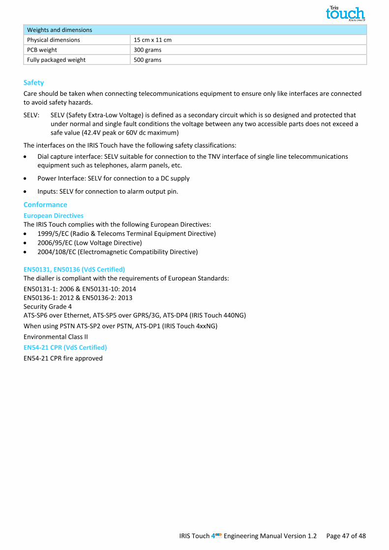
IRIS Touch Engineering Manual Version 1.2 Page 47 of 48
Weights and dimensions
Physical dimensions 15 cm x 11 cm
PCB weight 300 grams
Fully packaged weight 500 grams
Safety Care should be taken when connecting telecommunications equipment to ensure only like interfaces are connected to avoid safety hazards.
SELV: SELV (Safety Extra-Low Voltage) is defined as a secondary circuit which is so designed and protected that under normal and single fault conditions the voltage between any two accessible parts does not exceed a safe value (42.4V peak or 60V dc maximum)
The interfaces on the IRIS Touch have the following safety classifications:
Dial capture interface: SELV suitable for connection to the TNV interface of single line telecommunications equipment such as telephones, alarm panels, etc.
Power Interface: SELV for connection to a DC supply
Inputs: SELV for connection to alarm output pin.
Conformance European Directives The IRIS Touch complies with the following European Directives:
1999/5/EC (Radio & Telecoms Terminal Equipment Directive)
2006/95/EC (Low Voltage Directive)
2004/108/EC (Electromagnetic Compatibility Directive) EN50131, EN50136 (VdS Certified) The dialler is compliant with the requirements of European Standards:
EN50131-1: 2006 & EN50131-10: 2014 EN50136-1: 2012 & EN50136-2: 2013 Security Grade 4 ATS-SP6 over Ethernet, ATS-SP5 over GPRS/3G, ATS-DP4 (IRIS Touch 440NG)
When using PSTN ATS-SP2 over PSTN, ATS-DP1 (IRIS Touch 4xxNG)
Environmental Class II
EN54-21 CPR (VdS Certified)
EN54-21 CPR fire approved

The future of security, secured IP by security professionals, for the professional security industry
Installation and Service Engineer Support Telephone: +44 871 977 1133 (Calls are charged at 10p a minute from a BT landline. Calls from mobiles or other providers may be higher)
Sales Enquiries: +41 435 080 870
Email: [email protected] www.chironsc.com
CHIRON SECURITY COMMUNICATIONS AG
BAARERSTRASSE 19 6300 ZUG
SWITZERLAND
The information contained is supplied without liability for any errors or omissions. No part may be reproduced or used except as authorized by contract or other written permission. The copyright and foregoing restriction on reproduction and use extend to all media in which the information may be embedded.
© 2014 Chiron Security Communications AG