Embed Size (px)
Citation preview

2018 GROUP A PROPOSEDCHANGES TO THE I-CODESCOLUMBUS COMMITTEE ACTIONHEARINGS
April 15–23, 2018Columbus Convention CenterColumbus, Ohio
IRC — Plumbing

First Printing
Publication Date: February 2018
Copyright © 2018 By
International Code Council, Inc.
ALL RIGHTS RESERVED. This 2018-2019 Code Development Cycle, Group A (2018) Proposed Changes to the 2018 International Codes is a copyrighted work owned by the International Code Council, Inc. Without advanced written permission from the copyright owner, no part of this book may be reproduced, distributed, or transmitted in any form or by any means, including, without limitations, electronic, optical or mechanical means (by way of example and not limitation, photocopying, or recording by or in an information storage retrieval system). For information on permission to copy material exceeding fair use, please contact: Publications, 4051 West Flossmoor Road, Country Club Hills, IL 60478 (Phone 1-888-422-7233). Trademarks: “International Code Council,” the “International Code Council” logo are trademarks of the International Code Council, Inc.
PRINTED IN THE U.S.A.

2018 GROUP A – PROPOSED CHANGES TO THE INTERNATIONAL RESIDENTIAL CODE – PLUMBING/
MECHANICAL
PLUMBING/MECHANICAL CODE COMMITTEE W. Travis Lindsey, MCP, Chair Sr. Plans Examiner City of Scottsdale Scottsdale, AZ Marguerite Carroll, Vice Chair Codes and Regulatory Services Manager Underwriters Laboratories Fremont, CA John Ainslie Rep: National Association of Home Builders Owner Ainslie Group Virginia Beach, VA Richard C. Anderson Division Manager/Deputy Building Official City of Austin Austin, TX Roland Asp, CET Manager of Installation Standards National Fire Sprinkler Association Linthicum Heights, MD Pennie Feehan Rep: Copper Development Association Owner Pennie L. Feehan Consulting Palm Springs, CA R. L. Ric Johnson, CAPS, DHTI+ Rep: National Association of Home Builders President/CEO Right at Home Technologies Ada, OH
Nick McAndrew, PE Professional Engineer I (Civil/Construction) NY Department of State Division of Buildings Standards and Codes Albany, NY David W. Perry Sr. Combination Inspector City of Richardson Richardson, TX Thomas Polino Plumbing Subcode Official West Windsor Township West Windsor, NJ Loren K. Swanson, BSIE Rep: National Association of Home Builders Retired from Southern Michigan Co. Jackson, MI Jeremy Wright Rep: National Association of Home Builders President J. Wright Building Company J. Wright Home Design Birmingham, AL Staff Secretariat: Fred Grable, PE Senior Staff Engineer - Plumbing International Code Council Central Regional Office Country Club Hills, IL Gregg Gress Senior Technical Staff International Code Council Central Regional Office 4051 W. Flossmoor Rd Country Club Hills, IL
RP1

TENTATIVE ORDER OF DISCUSSION 2018 PROPOSED CHANGES TO THE
INTERNATIONAL RESIDENTIAL BUILDING CODE – PLUMBING
The following is the tentative order in which the proposed changes to the code will be discussed at the public hearings. Proposed changes which impact the same subject have been grouped to permit consideration in consecutive changes. Proposed change numbers that are indented are those which are being heard out of numerical order. Indentation does not necessarily indicate that one change is related to another. Proposed changes may be grouped for purposes of discussion at the hearing at the discretion of the chair. Note that some RP code change proposals may not be included on this list, as they are being heard by another committee.
P1-18 Part II RB4-18 P58 -18 Part II
RP1-18 RP2-18
P11 -18 Part II P8-18 Part II P7-18 Part II
RP3-18 P63 -18 Part II P44 -18 Part II P45 -18 Part II P46 -18 Part II
RP4-18 P47 -18 Part II P50 -18 Part II P48-18 Part II P33 -18 Part II P71 -18 Part II F14 -18 Part II P97 -18 Part II P98 -18 Part II P79 -18 Part II P82 -18 Part II RP16-18 P77 -18 Part II
RP5-18 RP6-18 RP7-18 RP8-18 RP9-18 RP10-18
RP15-18 P87 -18 Part II P88 -18 Part II
RP11-18 P89 -18 Part II
RP12-18 P131-18 Part II P132-18 Part II P103-18 Part II P106-18 Part II P109-18 Part II P113-18 Part II P133-18 Part II
RP13-18 P115-18 Part II
RP14-18
RP2

RP1-18IRC: P2503.4Proponent: Gary Kozan, Ridgeway Plumbing, representing Ridgeway Plumbing ([email protected])
2018 International Residential Code
Revise as follows:
P2503.4 Building sewer testing. The building sewer shall be tested by insertion of a test plug at the point ofconnection with the public sewer, filling the building sewer with water and pressurizing the sewer to not less than a105-foot (3048 mm) head of water. The test pressure shall not decrease during a period of not less than 15 minutes.The building sewer shall be water tight at all points.A forced sewer test shall consist of pressurizing the piping to a pressure of not less than 5 psi (34.5 kPa) greater thanthe pump rating and maintaining such pressure for not less than 15 minutes. The forced sewer shall be water tight at allpoints.
Reason:For consistency with P2503.5.1, which requires a 5-foot head test for interior DWV systems. There is no reason foroutside drainage piping to be tested differently than inside piping.Cost ImpactThe code change proposal will not increase or decrease the cost of construction .This is only a change in test pressure. There is no extra labor or extra materials required that would impact the cost ofconstruction.Internal ID: 274
RP3

RP2-18IRC: P2503.5.1Proponent: Janine Snyder, City of Thornton, representing Colorado Association of Plumbing & Mechanical Officials(CAPMO) ([email protected])
2018 International Residential Code
P2503.5.1 Rough plumbing. DWV systems shall be tested on completion of the rough piping installation by water or,for piping systems other than plastic, by air, without evidence of leakage. Either test shall be applied to the drainagesystem in its entirety or in sections after rough-in piping has been installed, as follows:
1. Water test. Each section shall be filled with water to a point not less than 5 10 feet (1524 3048 mm)above the highest fitting connection in that section, or to the highest point in the completed system.Water shall be held in the section under test for a period of 15 minutes. The system shall prove leakfree by visual inspection.
2. Air test. The portion under test shall be maintained at a gauge pressure of 5 pounds per squareinch (psi) (34 kPa) or 10 inches of mercury column (34 kPa). This pressure shall be held withoutintroduction of additional air for a period of 15 minutes.
Reason:In the 2015 cycle, the IRC was changed to reduce the DWV water test pressure from 10 feet of head to 5 feet of head,yet the air test pressure remains at the equivalent of 10 feet of head or 5 psi. Since it is important enough tomaintain the equivalent air test pressure for the 10 feet of head then why are we creating a conflict within the samecode section between water and air tests. The DWV material performs in the exact same manner in an IRC building asit does in an IPC building, and the pipe used for DWV systems in an IRC building is the same pipe allowed for use in anIPC building. Furthermore, the integrity of the 10 feet of head test was important enough for the IPC committee todisapprove the reduction in the water test pressure in the 2015 and 2018 codes, so why are we risking a compromiseto the IRC structures by allowing a reduced test pressure that allows leaks in the system to go undetected until theycause damage. This code change corrects the conflict between the air and water test within the IRC requirements,and this code change will also address the conflicting test pressures between the IPC and the IRC for the water test.Cost ImpactThe code change proposal will not increase or decrease the cost of construction .The test is already a requirement within the code and a change in test pressure doesn't impact labor or materials.Internal ID: 2378
RP4

RP3-18IRC: P2705.1, P2708.6 (New), P2713.4 (New), SECTION P2726 (New), P2726.1 (New), P2726.2 (New),P2726.2.1 (New), P2726.2.2 (New), P2726.3 (New), P2726.4 (New), P2726.4.1 (New), P2726.4.2 (New),P2726.4.3 (New), P2726.5 (New), P2726.6 (New)Proponent: Jake Pauls, representing Jake Pauls Consulting Services ([email protected])
2018 International Residential Code
Revise as follows:
P2705.1 General. The installation of fixtures shall conform to the following:
1. Floor-outlet or floor-mounted fixtures shall be secured to the drainage connection and to the floor,where so designed, by screws, bolts, washers, nuts and similar fasteners of copper, copper alloy orother corrosion-resistant material.
2. Wall-hung fixtures shall be rigidly supported so that strain is not transmitted to the plumbingsystem.
3. Where fixtures come in contact with walls and floors, the contact area shall be water tight.4. Plumbing fixtures shall be usable including safety of users of showers, bathtubs and bathtub-shower
combinations in accordance with R301.1, R306, R307, R308, R311, R320, P2701, P2708, P2713, andP2726.
5. Water closets, lavatories and bidets. A water closet, lavatory or bidet shall not be set closer than15 inches (381 mm) from its center to any side wall, partition or vanity or closer than 30 inches (762mm) center-to-center between adjacent fixtures. There shall be a clearance of not less than 21inches (533 mm) in front of a water closet, lavatory or bidet to any wall, fixture or door.
6. The location of piping, fixtures or equipment shall not interfere with the operation of windows ordoors.
7. In flood hazard areas as established by Table R301.2(1), plumbing fixtures shall be located orinstalled in accordance with Section R322.1.6.
8. Integral fixture-fitting mounting surfaces on manufactured plumbing fixtures or plumbing fixturesconstructed on site, shall meet the design requirements of ASME A112.19.2/CSA B45.1 or ASMEA112.19.3/CSA B45.4.
Add new text as follows:
P2708.6 Grab Bars and Stanchions for Showers and Bathtub-Shower Combinations. Showers andbathtub-shower combinations shall provide stanchions or similar vertically-oriented, handholds typically not attachedto walls, and grab bars in accordance with P2726.
P2713.4 Grab Bars and Stanchions for Bathtubs and Bathtub-Shower Combinations. Bathtubs andbathtub-shower combinations shall provide grab bars or stanchions in accordance with P2726.
SECTION P2726 GRAB BARS FOR BATHTUBS AND SHOWERS.
P2726.1 General. Grab Bars and Stanchions for Bathtubs, Bathtub-Shower Combinations, and Showers. Bathtubs,bathtub-shower combinations, and showers not required to be accessible shall be provided with grab bars orstanchions complying with P2726.1 through P2726.6. Dimensions specified are to the centerline of the grab bar orstanchion.
P2726.2 Grab Bars or Stanchions for Bathtubs and Bathtub-Showers. Grab bars or stanchions complyingwith P2726.2.1 and P2726.2.2 shall be provided at bathtubs and bathtub-shower combinations.
P2726.2.1 Vertical Grab bar or Stanchion. A vertical grab bar or stanchion shall be provided and shall complywith the following criteria.
1. Approach. The grab bar or stanchion shall be located so that it is usable without any obstruction. Anunobstructed clear floor space 21 inches (533 mm) wide minimum and 21 inches (533 mm) deepminimum, measured from the outer side of the bathtub, shall be provided and shall be located within12 inches (305 mm) of the grab bar or stanchion.
RP5

2. Length. The grab bar or stanchion shall be 36 inches (914 mm) long minimum.3. Position. The grab bar or stanchion shall be positioned in accordance with the following criteria:
3.1. The lower end of the grab bar or stanchion shall be 24 inches (610 mm) minimum and 27inches maximum above the finished floor.
3.2. Grab bars located inside a combination bathtub-shower compartment shall have theircenterline 6 inches (152 mm) minimum, measured horizontally, to the shower curtain rod and8 inches (200 mm) maximum, measured horizontally from the outer side of the bathtub.
3.3. Grab bars and stanchions shall be permitted within 6 inches (152 mm) outside of the outerside of the bathtub complying with P2726.2.1.1
P2726.2.2 Horizontal Grab Bar. A 24-inch (610 mm) long minimum grab bar shall be provided on the long, non-entryside of bathtubs and bathtub-shower combinations. The grab bar shall be installed in a horizontal position and shall becentered, plus or minus two inches, along the length of the tub. The horizontal grab bar shall be located 8 inches (205mm) minimum and 10 inches (255 mm) maximum above the tub rim.
Exception: A diagonal grab bar or, with 24 inches (610 mm) minimum length is permitted if installed with its higherend 12 inches (305mm) maximum from the control wall. The higher end of the grab bar shall be 25 inches (635 mm)minimum and 27 inches (685 mm) maximum above the tub rim. The lower end shall be located 8 inches (205 mm)minimum and 10 inches (255 mm) maximum above the tub rim.
P2726.3 Vertical Grab Bar or Stanchion for Showers. A vertical grab bar or stanchion shall be provided forshowers. The vertical grab bar or stanchion shall be located either interior to or outside the shower compartment,within 3 inches (76 mm) of the compartment access and egress opening. The grab bar or stanchion shall be 24 inches(610 mm) long minimum with its lower end 39 inches (991 mm) maximum above the finished floor.
P2726.4 Other Details. Grab bars and stanchions shall comply with P2726.4
P2726.4.1 Cross Section. Grab bars and stanchions shall be circular in cross section having an outside diameter of1.25 inches (32 mm) minimum and 2 inches (51 mm) maximum.
P2726.4.2 Spacing. The space between the grab bar or stanchion and adjacent surfaces plus water controls shall be1.5 inches (32 mm) minimum.
P2726.4.3 Surface Hazards. Grab bars, stanchions and adjacent surfaces shall be free of sharp or abrasiveelements. Edges shall be rounded with a minimum radius of 0.25 inch (6 mm).
P2726.5 Structural Characteristics. Allowable stresses shall not be exceeded for materials used when a verticalor horizontal force of 250 pounds (1112 N) is applied an any point on the grab bar, stanchion, fasteners, mountingdevice or supporting structure. Grab bars and stanchions shall not rotate within their fittings.
P2726.6 Design and Installation for Water. Grab bars, stanchions, fasteners, mounting device or supportingstructure shall be designed and installed in accordance with P2701.1, with suitable materials, to withstand effects ofwater, including corrosion and other deterioration through their service life.
Reason:“Reason Statement” or Justif ication for Grab Bars and Stanchionsfor Bathtubs, Bathtub-Shower Combinations and ShowersComplying with New Requirements in IRC, especially Section P2726Proposed by Jake Pauls, BArch, CPE, HonDScIntroductionPoints of Control. Grab bars, handrails and stanchions are important building components providing—in combinationwith our hands and our feet—what are called (in ergonomics) “points of control” to maintain balance and aid inambulation and other movement activities that are crucial to utilizing means of egress for safety generally (in bothnormal and emergency conditions) and which pose dangers of injurious falls, the leading source of injuries in mostcountries, including the USA.A brief digression to explain “stanchions.” You see them routinely on transportation vehicles such as subway trains andcity buses. They are the vertical assemblies of graspable tubing that are fixed between ceilings, horizontal handrailsjust above head height, seats, floors, etc. usually located between seating and passageways or aisles. The term,
RP6
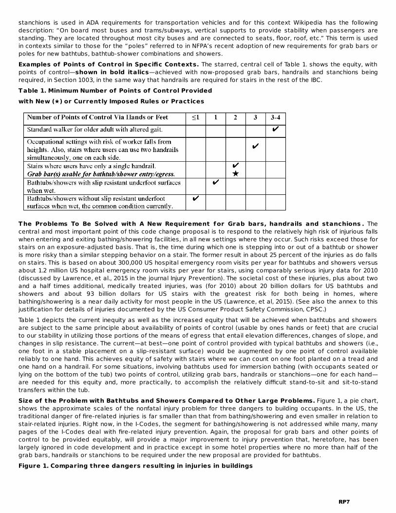
stanchions is used in ADA requirements for transportation vehicles and for this context Wikipedia has the followingdescription: “On board most buses and trams/subways, vertical supports to provide stability when passengers arestanding. They are located throughout most city buses and are connected to seats, floor, roof, etc.” This term is usedin contexts similar to those for the “poles” referred to in NFPA’s recent adoption of new requirements for grab bars orpoles for new bathtubs, bathtub-shower combinations and showers.Examples of Points of Control in Specific Contexts. The starred, central cell of Table 1. shows the equity, withpoints of control—shown in bold italics—achieved with now-proposed grab bars, handrails and stanchions beingrequired, in Section 1003, in the same way that handrails are required for stairs in the rest of the IBC.Table 1. Minimum Number of Points of Control Providedwith New (★) or Currently Imposed Rules or Practices
The Problems To Be Solved with A New Requirement for Grab bars, handrails and stanchions . Thecentral and most important point of this code change proposal is to respond to the relatively high risk of injurious fallswhen entering and exiting bathing/showering facilities, in all new settings where they occur. Such risks exceed those forstairs on an exposure-adjusted basis. That is, the time during which one is stepping into or out of a bathtub or showeris more risky than a similar stepping behavior on a stair. The former result in about 25 percent of the injuries as do fallson stairs. This is based on about 300,000 US hospital emergency room visits per year for bathtubs and showers versusabout 1.2 million US hospital emergency room visits per year for stairs, using comparably serious injury data for 2010(discussed by Lawrence, et al., 2015 in the journal Injury Prevention). The societal cost of these injuries, plus about twoand a half times additional, medically treated injuries, was (for 2010) about 20 billion dollars for US bathtubs andshowers and about 93 billion dollars for US stairs with the greatest risk for both being in homes, wherebathing/showering is a near daily activity for most people in the US (Lawrence, et al, 2015). (See also the annex to thisjustification for details of injuries documented by the US Consumer Product Safety Commission, CPSC.)Table 1 depicts the current inequity as well as the increased equity that will be achieved when bathtubs and showersare subject to the same principle about availability of points of control (usable by ones hands or feet) that are crucialto our stability in utilizing those portions of the means of egress that entail elevation differences, changes of slope, andchanges in slip resistance. The current—at best—one point of control provided with typical bathtubs and showers (i.e.,one foot in a stable placement on a slip-resistant surface) would be augmented by one point of control availablereliably to one hand. This achieves equity of safety with stairs where we can count on one foot planted on a tread andone hand on a handrail. For some situations, involving bathtubs used for immersion bathing (with occupants seated orlying on the bottom of the tub) two points of control, utilizing grab bars, handrails or stanchions—one for each hand—are needed for this equity and, more practically, to accomplish the relatively difficult stand-to-sit and sit-to-standtransfers within the tub.Size of the Problem with Bathtubs and Showers Compared to Other Large Problems. Figure 1, a pie chart,shows the approximate scales of the nonfatal injury problem for three dangers to building occupants. In the US, thetraditional danger of fire-related injuries is far smaller than that from bathing/showering and even smaller in relation tostair-related injuries. Right now, in the I-Codes, the segment for bathing/showering is not addressed while many, manypages of the I-Codes deal with fire-related injury prevention. Again, the proposal for grab bars and other points ofcontrol to be provided equitably, will provide a major improvement to injury prevention that, heretofore, has beenlargely ignored in code development and in practice except in some hotel properties where no more than half of thegrab bars, handrails or stanchions to be required under the new proposal are provided for bathtubs.Figure 1. Comparing three dangers resulting in injuries in buildings
RP7
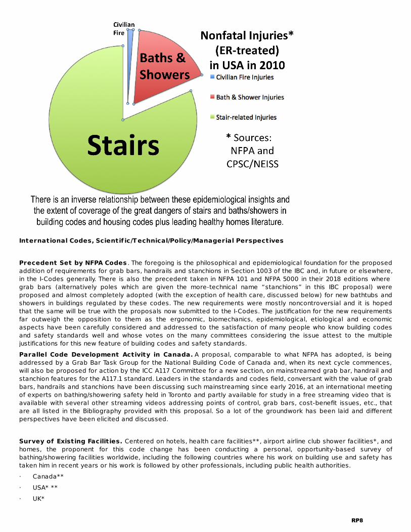
International Codes, Scientif ic/Technical/Policy/Managerial Perspectives Precedent Set by NFPA Codes . The foregoing is the philosophical and epidemiological foundation for the proposedaddition of requirements for grab bars, handrails and stanchions in Section 1003 of the IBC and, in future or elsewhere,in the I-Codes generally. There is also the precedent taken in NFPA 101 and NFPA 5000 in their 2018 editions wheregrab bars (alternatively poles which are given the more-technical name “stanchions” in this IBC proposal) wereproposed and almost completely adopted (with the exception of health care, discussed below) for new bathtubs andshowers in buildings regulated by these codes. The new requirements were mostly noncontroversial and it is hopedthat the same will be true with the proposals now submitted to the I-Codes. The justification for the new requirementsfar outweigh the opposition to them as the ergonomic, biomechanics, epidemiological, etiological and economicaspects have been carefully considered and addressed to the satisfaction of many people who know building codesand safety standards well and whose votes on the many committees considering the issue attest to the multiplejustifications for this new feature of building codes and safety standards.Parallel Code Development Activity in Canada. A proposal, comparable to what NFPA has adopted, is beingaddressed by a Grab Bar Task Group for the National Building Code of Canada and, when its next cycle commences,will also be proposed for action by the ICC A117 Committee for a new section, on mainstreamed grab bar, handrail andstanchion features for the A117.1 standard. Leaders in the standards and codes field, conversant with the value of grabbars, handrails and stanchions have been discussing such mainstreaming since early 2016, at an international meetingof experts on bathing/showering safety held in Toronto and partly available for study in a free streaming video that isavailable with several other streaming videos addressing points of control, grab bars, cost-benefit issues, etc., thatare all listed in the Bibliography provided with this proposal. So a lot of the groundwork has been laid and differentperspectives have been elicited and discussed. Survey of Existing Facilities. Centered on hotels, health care facilities**, airport airline club shower facilities*, andhomes, the proponent for this code change has been conducting a personal, opportunity-based survey ofbathing/showering facilities worldwide, including the following countries where his work on building use and safety hastaken him in recent years or his work is followed by other professionals, including public health authorities.· Canada**· USA* **· UK*
RP8

· Sweden**· Finland· Netherlands· Italy· Singapore*· Australia**· New Zealand· JapanThe survey is documented in many hours of video and thousands of photographs plus many measurements, inresidential occupancies, of three-, four-, five-piece bathrooms ranging in size from a few square meters (20 squarefeet) to spaces big enough to park an automobile, occasionally with tubs and showers almost that big. Generally, themore compact the bathroom, the easier it is to provide the needed points of control—and with very substantial costsavings.Hotels Surveyed. They were operated by Marriott, Sheraton, Intercontinental, Holiday Inn, Best Western, Hyatt, Hiltonin almost of the countries listed above. In some of them, meetings were held with hotel managers and thoseresponsible for risk management. Detailed Justif ications for Specif ic New Sections in IRC P2705.1 already has the heart of the proposal in its item 4, “Plumbing fixtures shall be usable.” The proposal simplyfleshes this out with sufficient detail to implement this objective.P2708. The new text, for the Section for Showers, clarifies, for Showers, that stanchions (sometimes termed “poles,”as in NFPA’s requirements) are equivalent to required grab bars of the conventional sort. It directs IRC users to a newP2726 for requirements.P2713. 4. The new text, for the section on Bathtubs, directs users to a new P2726 for requirements.P2726.1. This new text introduces the detailed requirements and clarifies that dimensions (taken at right angles to thegrab bar or stanchion) are to the centerline of the device.P2726.2. These detailed requirements, here for vertical points of control, are based on research findings andrecommendations described below and are roughly similar to what NFPA adopted for the 2018 edition of NFPA 101 andNFPA 5000. They are also being considered currently for the National Building Code of Canada.In these detailed requirements for the vertical points of control, the first thing is to establish where within the plan ofthe bathroom, they will adequately serve users. This is based on Section R307of the IRC which, along with FigureR307.1, sets the required minimum 21-inch (533 mm) clearances in front of fixtures (toilet, lavatory and tub), the areasthrough which bathers need to move reasonably unobstructed to access the tub and to exit the tub. The requiredpoints of control have to be within 12 inches (905 mm), measured horizontally, of these clear areas. The dimensions shown here, plus the general superiority of vertical grab bars for ambulatory transfers, are based onextensive Canadian research over the last two decades as well as a meeting of US and Canadian experts in early2016 that is partially available—for its presentations of Principal Investigators—on free steaming video (with links alsoprovided in the Bibliography). An example of a vertical pole that is recognized as at least equivalent to theconventional vertical grab bar is shown in Figure 2, above, along with relevant discussion that supports the superiorityof a properly installed stanchion which can be more easily positioned where the tub is most likely to be accessed.These dimensions are generally similar to what NFPA adopted for its 2018 editions of NFPA 101 and NFPA 5000. Theyare stated slightly differently in the IBC proposal to take better account of bathtubs that do not have walls on one tothree sides. As in the NFPA-adopted requirements, P2726.2.1.3(2) addresses the often-missed issue of a wall-mountedconventional, vertical grab bar interfering with the shower curtain getting a good seal on the end wall.Figure 2. Demonstration set up of both conventional grab bars (nominally meeting the length andlocation criteria of proposed IRC requirements and a stanchion plus a horizontally-fixed section—likea handrail—of the same tubing used for the stanchion (both completely meeting the length, locationand structural strength requirements of proposed IRC requirements (which are consistent with IBC,ICC A117.1 and NFPA requirements)
RP9

Besides aesthetic advantages, the stanchion and the full-tub-length bars /tubing are clearly superior in placementflexibility—as they do not require walls for attachment—and better performance for a wider range of users and usesincluding here, especially for the stanchion, serving a use that is not addressed in P2726 for stand-to-sit and sit-to-stand transfers for toilet users that might be a bonus benefit used more frequently than would be uses related tobathing and showering. This is especially the case in small, residential-use bathrooms such as serving dwellings, where(for space and plumbing efficiency reasons) often have bathtubs and toilets in close proximity. This is addressedfurther in the Cost Impact section of the justification.Note that the straight tubing based stanchion and the horizontal bar/tubing are not held by mere compression fit; theyare held by adhesive that is permanent and waterproof. The lower part of the stanchion was tested at sustained loadsof 300 pounds of horizontal, shearing force without any indication of failure. Its fixing plate shear area exceeds theshear area of conventional grab bar screws by a factor of six and unlike the case for conventional grab bar screwsthere is no issue with water intrusion and corrosion as well as deterioration of the structural backing for the screws.(See the section below describing field observations of serious deterioration of conventional grab bars fixing detailsthat are often not designed for water intrusion.) Here it should be noted that automobiles, today, utilize high-performance adhesives where, in the past, screws were the norm but these, and the necessary perforations in parts,performed poorly from a corrosion perspective. Water pumps as well as body panels and headlamp plus taillightassemblies are examples of how modern automobiles are built with waterproof, automotive-grade adhesives.Examples of greater use of modern adhesives are also found increasingly in building construction.Here it must be emphasized that grab bars and stanchions have to be structurally installed; some of the productsavailable in the marketplace, e.g., suction-cup grab bars—that have a temporary and precarious adhesion to smoothtiles—and compression-fit (via a jackscrew mechanism) temporary transfer poles do not meet the structuralrequirements imposed in the proposed new requirements, the same structural performance requirements applied—withstanding loads of 250 pounds—currently applicable to conventional grab bars in the IBC. In Figure 2, below, thephotograph shows a demonstration bathtub-shower combination with a redundant set of both conventional (verticaland diagonal) grab bars and (vertical and horizontal, straight lengths of tubing fixed at their ends)—the latter easilymeet the 250-pound structural load criterion.P2726.2.2 Horizontal Grab Bar. As with the vertical grab bar, described above (for P27262.1), the dimensions and
RP10

need for this second grab bar are based on Canadian research identified in the Bibliography and is addressed in thevideo of the presentation by Dr. Nancy Edwards, Principal Investigator of the early Canadian work which alsoaddressed the option of a diagonal grab bar provided via the exception to 2726.2. Note that the base requirementcovers installations where the bathtub is not enclosed on one or more sides with a wall. Such horizontal grab bars areintended for use by persons using the tub for immersion bathing which requires stand-to-sit and sit-to-stand transfersthat utilize a horizontal or diagonal grab bar (and might also utilize a vertical grab bar or pole addressed by 27.2.1).2726.2.2 permits horizontal handrails, which could be the same tubing used for the stanchion, to be used in a horizontalorientation. These could be longer (e.g., full tub length) than conventional, horizontal grab bars which need a parallelwall for support, unlike the horizontal tubing fixed between end walls only.P2726.2.3. Vertical Grab Bar or Stanchion for Showers. Because of the variety of dedicated showers,especially in plan shape and size, this requirement is stated in a relatively flexible fashion relying more on aperformance approach than specific dimensions, other than the minimum length and lower end position that takes intoaccount various statures of users as well as the possibility there might be a seat in the shower. The inclusion of astanchion takes into account the structural differences between bathtubs and free-standing showers; the latter wouldbe good candidates for a stanchion positioned between the ceiling and the floor just outside the shower entrance.2726.4. Other Details. Generally the requirements referenced here are based mostly on current requirements ofICC A117.1-2017 and with a new provision that addresses often-seen issues of water damage to conventional grabbars that range from the cosmetic to the catastrophic.27.26.4.1 Cross Section. This is the same as ICC A117.1-2017 without an exception for noncircular sections whichare rarely seen within bathrooms.P2726.4.2. Spacing. This is based on a simplified version of ICC A117.1-2017.P2726.4.3. Surface Hazards. This expands on a requirement, P2701.1.P2726.5. Structural Characteristics. This is based on current requirements of ICC A117.12726.6. Design and Installation for Water. This last section is new and it addresses a serious problem with anon-trivial number of grab bars that have been seen in hotels, especially in the USA and Canada. Many are notdesigned, installed and maintained to address deterioration and corrosion problems with conventional, wall-mountedgrab bars due to easy water intrusion and entrapment between conventional grab bar mounting plates and the coversfastened over them. Often, when water is entrapped here, there is no way for it to drain out, particularly from the lowerportion of the enclosed space.Problems Found in the Field with Conventional Grab BarsHere follows some detail on what has been observed in the field on two large problems addressed in 2726.6 as well asin 2726.2.1.3(2).During the course of his opportunity-based survey of grab bars provided for bathrooms in hotel guest rooms theproponent of this code change has found two problems with many installations.The first, affecting over 50 percent of the surveyed bathtub-shower combinations, comes from placement of verticalgrab bars underneath—and within a few inches horizontally of the end bracket for shower curtains. This makes sealingthe shower curtain against the end wall of the bathtub-shower combination very difficult so that the danger of watergetting outside the bathtub, on the adjacent floor is heightened unreasonably and needlessly. The proposed section1003.8.2.1.3(3) addresses this problem as follows: “If attached to a wall, a grab bar or handrail shall be located insidethe bathtub or combination bathtub-shower compartment and shall be no closer than 6 inches (152 mm), measuredhorizontally to the shower curtain rod.”A much more worrying problem is found with a smaller percentage of conventional, wall-mounted grab bar installations,specifically grab bars which have cover plates over the screw plate onto which the tube of the grab bar is welded.There is invariably a space between the hole in the cover plate through which the tubing (grasped) portion of the grabbar passes and the tubing itself. Water can easily enter here and get trapped by the cover plate thus creating a poolof water and debris (hair, shampoo residue, etc.) from the showering process.Aside from the hygiene problem here, there is a greatly heightened risk of two structural problems. One is waterintrusion into the wall, around the fixing screws—typically two or three for each end of the grab bar, causingdeterioration of the backing material so the screws become loose enough to be extractable with ones fingers. Thesecond problem is equally worrisome especially as the quality of the steel used in (off-shore) grab bars is relativelypoor in terms of corrosion of the screws and, less often, the mounting plates. The worst case seen recently had theheads of all the screws holding a grab bar so corroded that their heads were completely deteriorated and the grabbar could be pulled away from the walls with little force by one hand—clearly far, far less than the stipulated load of250 pounds that codes in the US stipulate for structural strength.The proponent has many photographs of these problems as well as a few videos showing how loose the grab barshave become due to corrosion as well as backing deterioration from water. One such photograph is provided in Figure
RP11
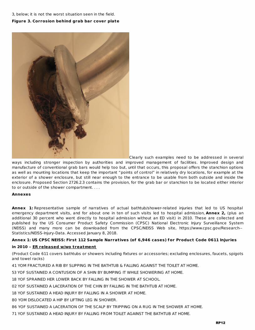
3, below; it is not the worst situation seen in the field.Figure 3. Corrosion behind grab bar cover plate
Clearly such examples need to be addressed in severalways including stronger inspection by authorities and improved management of facilities. Improved design andmanufacture of conventional grab bars would help too but, until that occurs, this proposal offers the stanchion optionsas well as mounting locations that keep the important “points of control” in relatively dry locations, for example at theexterior of a shower enclosure, but still near enough to the entrance to be usable from both outside and inside theenclosure. Proposed Section 2726.2.3 contains the provision, for the grab bar or stanchion to be located either interiorto or outside of the shower compartment. . . .Annexes Annex 1: Representative sample of narratives of actual bathtub/shower-related injuries that led to US hospitalemergency department visits, and for about one in ten of such visits led to hospital admission, Annex 2, (plus anadditional 30 percent who went directly to hospital admission without an ED visit) in 2010. These are collected andpublished by the US Consumer Product Safety Commission (CPSC) National Electronic Injury Surveillance System(NEISS) and many more can be downloaded from the CPSC/NEISS Web site, https://www.cpsc.gov/Research--Statistics/NEISS-Injury-Data. Accessed January 8, 2018.Annex 1: US CPSC NEISS: First 112 Sample Narratives (of 6,946 cases) for Product Code 0611 Injuriesin 2010 – ER released w/wo treatment(Product Code 611 covers bathtubs or showers including fixtures or accessories; excluding enclosures, faucets, spigotsand towel racks)41 YOM FRACTURED A RIB BY SLIPPING IN THE BATHTUB & FALLING AGAINST THE TOILET AT HOME.53 YOF SUSTAINED A CONTUSION OF A SHIN BY BUMPING IT WHILE SHOWERING AT HOME.18 YOF SPRAINED HER LOWER BACK BY FALLING IN THE SHOWER AT SCHOOL.02 YOF SUSTAINED A LACERATION OF THE CHIN BY FALLING IN THE BATHTUB AT HOME.18 YOF SUSTAINED A HEAD INJURY BY FALLING IN A SHOWER AT HOME.80 YOM DISLOCATED A HIP BY LIFTING LEG IN SHOWER.86 YOF SUSTAINED A LACERATION OF THE SCALP BY TRIPPING ON A RUG IN THE SHOWER AT HOME.71 YOF SUSTAINED A HEAD INJURY BY FALLING FROM TOILET AGAINST THE BATHTUB AT HOME.
RP12

68 YOF SPRAINED AN ANKLE BY FALLING IN A SHOWER.47 YOF FRACTURED A KNEE BY FALLING IN THE SHOWER AT HOME.02 YOF SUSTAINED A LACERATION OF THE CHIN BY FALLING IN THE BATHTUB.22 YOM SPRAINED A FOOT WHILE STEPPING OUT OF A SHOWER AT JAIL.23 YOF SUSTAINED A CONTUSION OF A FOOT BY TRIPPING ON A RUG & STRIKING AGAINST A TUB AT HOME.40 YOM SUSTAINED A LACERATION OF THE NOSE FROM BEING STRUCK BY THE SHOWER HEAD IN THE SHOWER AT HOME.21 MOM RUPTURED AN EAR DRUM WITH A COTTON-TIPPED SWAB WHILE BATHING IN TUB AT HOME.48 YOF SUSTAINED A CONTUSION OF THE NECK BY FALLING IN THE BATHTUB AT HOME.04 YOF SLIPPED IN BATHTUB FELL AND INJURED FACE DX/ FACIAL LAC L KNEE STR10 YOF FELL OUT OF SHOWER AND INJURED L KNEE. HAS ABRASION TO KNEE ALSO80 YOF FELL IN SHOWER AT HOME HIT HEAD. DX/ HEAD INJURY94 YOM SLIPPED AND FELL IN SHOWER AND HIT FACE ON FLOOR. DX/ FACIAL FX55 YOM SLL LEG HEMATOMA72 YOF CAUGHT FOOT IN TUB, INJURING LOWER LEG. NOW HAS HEMATOMA AND INCREASING PAIN.22 YOF AT HOME FAINTED WHILE IN SHOWER AND FELL CUTTING FOREHEAD.26 YOF SLIPPED AND FELL IN TUB DX: KNEE STRAIN90 YOF GETTING OUT OF SHOWER WITH WALKER SLIPPED ON THE FLOOR AND HIT HEAD DX/ SCALP ABRASION30 YOM SLIPPED AND FELL INTO TUB DX: CONTUSION TO BACK51 YOF SLIPPED IN TUB AND HIT HEAD DX/ SCALP LAC60 YOF SLIPPED AND FELL IN TUB DX: CONTUSION TO COCCYX44 YOM FELL AND HIT ABDOMEN ON BATHTUB AT HOME. DX/ ABDOMINAL CONTUSION04 YOM WITH CUT TO FACE FELL IN TUB DX: LACERATION TO FACE51 YOF AT HOME FELL AT 5PM WHEN LOST BALANCE AND HIT L SIDE OF RIBS ON BATHTUB.33 YOF SLIPPED AND FELL IN TUB DX: HEAD LACERATION23 MOM FELL IN BATHTUB AT HOME AND HIT CHIN CAUSING LACERATION.62 YOM WITH BACK PAIN FELL INTO TUB DX; CONTUSION TO LOWER BACK 63 YOF FELL INTO BATHTUB / NO INJURIES OR COMPLAINTS54 YOM SLIPPED AND FELL IN TUB DX: RIB FRACTURE02 YOM SLIPPED IN TUB AT HOME AND INJURED FACE DX/ CHIN LAC25 YOF WITH CHEST PAIN AFTER FALL INTO TUB DX: CONTUSION TO CHEST84 YOM FELL OUT OF SHOWER ON TO THE FLOOR AT HOME HIT HEAD DX/ HEAD INJURY85 YOF SLIPPED AND FELL IN TUB AND HIT HEAD AT HOME DX/ HEAD INJURY06 YOM AT HM WAS TAKING A BATH & SWIMMING IN TUB WHEN HE STRUCK HIS HEAD AGAINST FAUCET CAUSING HEADLACERATION.28 YOM AT HOME FELL IN SHOWER. WAS RESPONSIVE PER EMS.26 YOF SLIPPED / FELL IN THE SHOWER DX: R EAR LAC. / HEAD & R SHOULDER CONTUSION36 YOF THIS AM SLIPPED WHILE TRYING TO GET OUT OF BATHTUB AND LANDED ON BUTTOCKS.28 YOF RIPPED FINGER NAIL OFF WHEN SLIPPED IN THE SHOWER AND THE NAIL BENT BACKWARDS.26 YOF INJURED KNEE STEPPING OUT OF SHOWER DX/ RIGHT KNEE SPRAIN50 YOM FELL IN BATHTUB AND HIT CHEST DX/ RIB FX83 YOM CUT SCROTUM FELL IN TUB DX: LACERATION TO SCROTUM71 YOF FELL OUT OF BATHTUB AT HOME AND HIT HEAD ON THE FLOOR DX/ HEAD INJURY89 YOF FELL IN TUB HITTING HEAD DX: CLOSED HEAD INJURY69 YOF WAS IN SHOWER AND FELL BACKWARDS STRIKING HER BACK.08 YOF AT HOME LACERATED FACE ABOVE R ORBITAL. HIT HER HEAD ON SOAP DISH WHILE SHOWERING. NO LOC.
RP13

40 YOM SLIPPED AND FELL IN SHOWER AND INJURED CHEST. DX/ RIB FX17 YOF FELL IN TUB HURT NECK DX: NECK STRAIN 23 YOM INJURED LOWER BACK BENDING OVER IN SHOWER AT HOME DX/ LUMBAR STRAIN83 YOF FELL IN THE TUB AT ASSISTED LIVING AND INJURED SHOULDER DX/ RT SHOULDER CONTUSION02 YOM HIT FACE ON BATHTUB AT HOME DX/ FACIAL LAC74 YOM FELL AND HIT HEAD IN TUB DX: CONTUSION TO HEAD85 YOF SLIPPED AND FELL GETTING OUT OF TUB DX: CONTUSION TO HIP58 YOF SLIPPED AND FELL INTO TUB HIT HEAD DX: CLOSED HEAD INJURY13 MOM AT HOME FELL IN BATHTUB AND HIT FOREHEAD AND MOUTH.06 YOM SLIPPED IN BATHTUB AND HIT HEAD DX/ HEAD CONTUSION78 YOM SLIPPED AND FELL IN TUB DX: LACERATION TO HEAD08 YOM SLIPPED IN TUB TWISTED ANKLE DX: ANKLE STRAIN51 YOF HIT HEAD ON SOAP DISH IN SHOWER 2 TIMES THIS WEEK HAS HEADACHE DX/ CONCUSSION51 YOF SLIPPED IN SHOWER AND INJURED KNEE AT HOME DX/ RIGHT KNEE CONTUSION83 YOM SLIPPED AND FELL IN THE SHOWER LAST NIGHT AND INJURED BACK DX/ BACK PAIN31 YOM HIT EYE WITH TOWEL WHILE GETTING OUT OF THE SHOWER AT HOME DX/ RIGHT EYE CORNEAL ABRASION24 YOF FELL GETTING OUT OF SHOWER HIT HEAD DX/ SCALP LAC48 YOF SLIPPED IN SHOWER HIT HEAD + LOC DX/ HEAD INJURY11 YOM SLIPPED IN SHOWER AND INJURED LEG. DX/ LEFT LEG CONTUSION30 YOF SLIPPED AND FELL INTO TUB DX: CONTUSION TO HIP18 MOM FELL IN TUB DX: LACERATION TO FACE46 YOF SLIPPED AND FELL IN TUB DX: CONTUSION TO LOWER BACK30 YOM CUT HAND ON BROKEN SOAP DISH AT HOME. DX// RIGHT HAND LAC70 YOF SLIPPED AND FELL IN TUB DX: CONTUSION TO CHEST31 YOM CUT THUMB ON SHOWER DRAIN THIS AM.62 YOF SLIPPED IN THE SHOWER AND FELL ON THE FLOOR AT HOME DX/ LEFT WRIST SPRAIN67 YOM FELL GETTING OUT OF SHOWER HIT HEAD ON TUB AT HOME DX/ SCALP CONTUSION45 YOF PASSED OUT IN SHOWER AT GROUP HOME HIT HEAD. DX/ HEAD INJURY04 YOF FELL IN BATHTUB AND HIT MOUTH DX/ LIP LAC43 YOM SLIPPED IN BATHTUB AND INJURED KNEE DX/ LEFT KNEE CONTUSION15 YOM TAKING SHOWER AND SHOWER DOOR SHATTERED AND PT FEET WERE CUT WITH THE GLASS AT HOME DX/ BILATFOOT LAC73 YOF AT 9AM TODAY WAS GETTING OUT OF TUB AND SLIPPED AND BUMPED L RIBS ON THE TUB. C/O RIB PAIN.87 YOF BENT DOWN TO PUT SCALE AWAY FELL AND HIT INTO TUB AT HOME DX/ LEFT HIP CONTUSION22 YOM FELL IN TUBAT HOME AND INJURED CHEST DX/ RIB FX40 YOF SLIPPED GETTING OUT OF BATHTUB AND INJURED LOWER BACK DX/ LOW BACK PAIN34 YOM FELL AND HIT TUB DX: SHOULDER STRAIN70 YOF SLIPPPED FELL HIT CHEST ON SIDE OF TUB DX: CONTUSION TO CHEST89 YOF SLIPPED AND FELL IN THE SHOWER LAST NIGHT AT NURSING HOME INJURED CHEST DX/ CHEST CONTUSION44 YOM FELL IN TUB AND HIT CHEST DX.CHEST CONTUSION36 YOF SLIPPED AND FELL IN TUB DX: LACERATION TO FACE56 YOM CUT WRIST ON BROKEN SHOWER KNOB AT HOME DX/ LEFT WRIST LAC88 YOF FELL AT HOME IN SHOWER AND HIT HEAD ON TUB DX/ SCALP CONTUSION51 YOM SLIPPED AND FELL IN TUB DX: NECK STRAIN23 YOM FELL IN BATH TUB AND INJURED CHEST DX/ CHEST CONTUSION
RP14
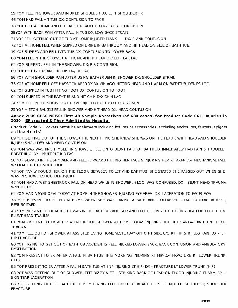
59 YOM FELL IN SHOWER AND INJURED SHOULDER DX/ LEFT SHOULDER FX46 YOM HAD FALL HIT TUB DX: CONTUSION TO FACE78 YOF FELL AT HOME AND HIT FACE ON BATHTUB DX/ FACIAL CONTUSION29YOF WITH BACK PAIN AFTER FALL IN TUB DX: LOW BACK STRAIN31 YOF FELL GETTING OUT OF TUB AT HOME INJURED FLANK DX/ FLANK CONTUSION72 YOF AT HOME FELL WHEN SLIPPED ON URINE IN BATHROOM AND HIT HEAD ON SIDE OF BATH TUB.19 YOF SLIPPED AND FELL INTO TUB DX: CONTUSION TO LOWER BACK08 YOM FELL IN THE SHOWER AT HOME AND HIT EAR DX/ LEFT EAR LAC62 YOM SLIPPED / FELL IN THE SHOWER. DX: RIB CONTUSION09 YOF FELL IN TUB AND HIT LIP. DX/ LIP LAC56 YOF WITH SHOULDER PAIN AFTER USING BATHBRUSH IN SHOWER DX: SHOULDER STRAIN75 YOF AT HOME FELL OFF HASSOCK APPROX 30 MIN AGO HITTING HEAD AND L ARM ON BATHTUB. DENIES LOC.62 YOF SLIPPED IN TUB HITTING FOOT DX: CONTUSION TO FOOT04 YOM SLIPPED IN THE BATHTUB AND HIT CHIN DX/ CHIN LAC34 YOM FELL IN THE SHOWER AT HOME INJURED BACK DX/ BACK SPRAIN25 YOF + ETOH BAL 313 FELL IN SHOWER AND HIT HEAD DX/ HEAD CONTUSIONAnnex 2: US CPSC NEISS: First 48 Sample Narratives (of 630 cases) for Product Code 0611 Injuries in2010 – ER treated & Then Admitted to Hospital(Product Code 611 covers bathtubs or showers including fixtures or accessories; excluding enclosures, faucets, spigotsand towel racks)89 YOF GETTING OUT OF THE SHOWER THE NEXT THING SHE KNEW SHE WAS ON THE FLOOR WITH HEAD AND SHOULDERINJURY; SHOULDER AND HEAD CONTUSION69 YOM WAS WASHING HIMSELF IN SHOWER, FELL ONTO BLUNT PART OF BATHTUB, IMMEDIATELY HAD PAIN & TROUBLEBREATHING. DX - MULTIPLE RIB FXS56 YOF SLIPPED IN THE SHOWER AND FELL FORWARD HITTING HER FACE & INJURiNG HER RT ARM- DX- MECHANICAL FALLW/ FRACTURE RT SHOULDER78 YOF FAMILY FOUND HER ON THE FLOOR BETWEEN TOILET AND BATHTUB, SHE STATED SHE PASSED OUT WHEN SHEWAS IN SHOWER;SHOULDER INJURY47 YOM HAD A WET SHEETROCK FALL ON HEAD WHILE IN SHOWER, +LOC, WAS CONFUSED. DX - BLUNT HEAD TRAUMAW/BRIEF LOC62 YOM HAD A SYNCOPAL TODAY AT HOME IN THE SHOWER INJURING EYE AREA- DX- LACERATION TO FACE( EYE)78 YOF PRESENT TO ER FROM HOME WHEN SHE WAS TAKING A BATH AND COLLAPSED - DX- CARDIAC ARREST,RESUSCITAED43 YOM PRESENT TO ER AFTER HE WAS IN THE BATHTUB AND SLIP AND FELL GETTING OUT HITTING HEAD ON FLOOR- DX-BLUNT HEAD TRAUMA81 YOM PRESENT TO ER AFTER A FALL IN THE SHOWER AT HOME TODAY INJURING THE HEAD AREA- DX- BLUNT HEADTRAUMA41 YOM FELL OUT OF SHOWER AT ASSISTED LIVING HOME YESTERDAY ONTO RT SIDE C/O RT HIP & RT LEG PAIN. DX - RTHIP FRACTURE80 YOF TRYING TO GET OUT OF BATHTUB ACCIDENTLY FELL INJURED LOWER BACK; BACK CONTUSION AND AMBULATORYDYSFUNCTION92 YOM PRESENT TO ER AFTER A FALL IN BATHTUB THIS MORNING INJURING RT HIP-DX- FRACTURE RT LOWER TRUNK(HIP)88 YOF PRESENT TO ER AFTER A FAL IN BATH TUB AT SNF INJURING LT HIP- DX - FRACTURE LT LOWER TRUNK (HIP)88 YOF WAS GETTING OUT OF SHOWER, FELT DIZZY & FELL STRIKING BACK OF HEAD ON FLOOR INJURING LT ARM. DX -SKIN TEAR LACERATION88 YOF GETTING OUT OF BATHTUB THIS MORNING FELL TRIED TO BRACE HERSELF INJURED SHOULDER; SHOULDERFRACTURE
RP15
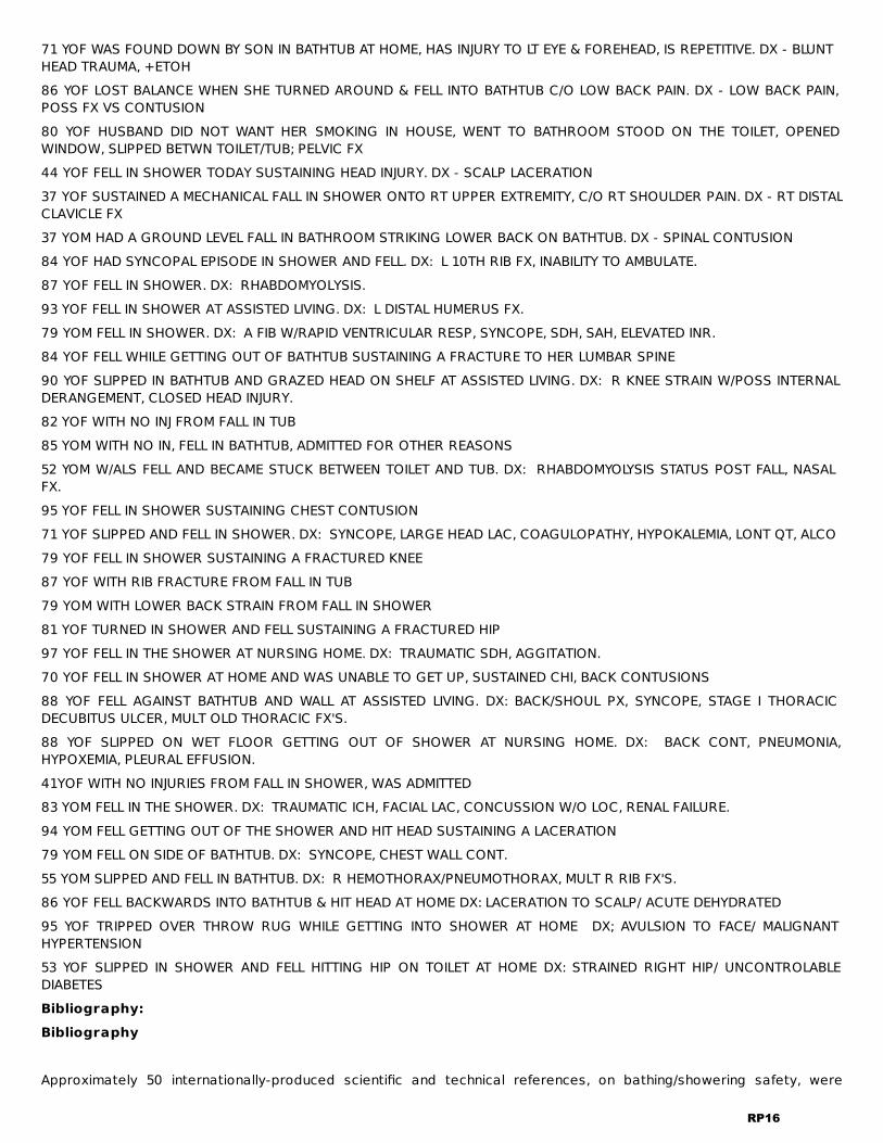
71 YOF WAS FOUND DOWN BY SON IN BATHTUB AT HOME, HAS INJURY TO LT EYE & FOREHEAD, IS REPETITIVE. DX - BLUNTHEAD TRAUMA, +ETOH86 YOF LOST BALANCE WHEN SHE TURNED AROUND & FELL INTO BATHTUB C/O LOW BACK PAIN. DX - LOW BACK PAIN,POSS FX VS CONTUSION80 YOF HUSBAND DID NOT WANT HER SMOKING IN HOUSE, WENT TO BATHROOM STOOD ON THE TOILET, OPENEDWINDOW, SLIPPED BETWN TOILET/TUB; PELVIC FX44 YOF FELL IN SHOWER TODAY SUSTAINING HEAD INJURY. DX - SCALP LACERATION37 YOF SUSTAINED A MECHANICAL FALL IN SHOWER ONTO RT UPPER EXTREMITY, C/O RT SHOULDER PAIN. DX - RT DISTALCLAVICLE FX37 YOM HAD A GROUND LEVEL FALL IN BATHROOM STRIKING LOWER BACK ON BATHTUB. DX - SPINAL CONTUSION84 YOF HAD SYNCOPAL EPISODE IN SHOWER AND FELL. DX: L 10TH RIB FX, INABILITY TO AMBULATE.87 YOF FELL IN SHOWER. DX: RHABDOMYOLYSIS.93 YOF FELL IN SHOWER AT ASSISTED LIVING. DX: L DISTAL HUMERUS FX.79 YOM FELL IN SHOWER. DX: A FIB W/RAPID VENTRICULAR RESP, SYNCOPE, SDH, SAH, ELEVATED INR.84 YOF FELL WHILE GETTING OUT OF BATHTUB SUSTAINING A FRACTURE TO HER LUMBAR SPINE90 YOF SLIPPED IN BATHTUB AND GRAZED HEAD ON SHELF AT ASSISTED LIVING. DX: R KNEE STRAIN W/POSS INTERNALDERANGEMENT, CLOSED HEAD INJURY.82 YOF WITH NO INJ FROM FALL IN TUB85 YOM WITH NO IN, FELL IN BATHTUB, ADMITTED FOR OTHER REASONS52 YOM W/ALS FELL AND BECAME STUCK BETWEEN TOILET AND TUB. DX: RHABDOMYOLYSIS STATUS POST FALL, NASALFX.95 YOF FELL IN SHOWER SUSTAINING CHEST CONTUSION71 YOF SLIPPED AND FELL IN SHOWER. DX: SYNCOPE, LARGE HEAD LAC, COAGULOPATHY, HYPOKALEMIA, LONT QT, ALCO79 YOF FELL IN SHOWER SUSTAINING A FRACTURED KNEE87 YOF WITH RIB FRACTURE FROM FALL IN TUB79 YOM WITH LOWER BACK STRAIN FROM FALL IN SHOWER81 YOF TURNED IN SHOWER AND FELL SUSTAINING A FRACTURED HIP97 YOF FELL IN THE SHOWER AT NURSING HOME. DX: TRAUMATIC SDH, AGGITATION.70 YOF FELL IN SHOWER AT HOME AND WAS UNABLE TO GET UP, SUSTAINED CHI, BACK CONTUSIONS88 YOF FELL AGAINST BATHTUB AND WALL AT ASSISTED LIVING. DX: BACK/SHOUL PX, SYNCOPE, STAGE I THORACICDECUBITUS ULCER, MULT OLD THORACIC FX'S.88 YOF SLIPPED ON WET FLOOR GETTING OUT OF SHOWER AT NURSING HOME. DX: BACK CONT, PNEUMONIA,HYPOXEMIA, PLEURAL EFFUSION.41YOF WITH NO INJURIES FROM FALL IN SHOWER, WAS ADMITTED83 YOM FELL IN THE SHOWER. DX: TRAUMATIC ICH, FACIAL LAC, CONCUSSION W/O LOC, RENAL FAILURE.94 YOM FELL GETTING OUT OF THE SHOWER AND HIT HEAD SUSTAINING A LACERATION79 YOM FELL ON SIDE OF BATHTUB. DX: SYNCOPE, CHEST WALL CONT.55 YOM SLIPPED AND FELL IN BATHTUB. DX: R HEMOTHORAX/PNEUMOTHORAX, MULT R RIB FX'S.86 YOF FELL BACKWARDS INTO BATHTUB & HIT HEAD AT HOME DX: LACERATION TO SCALP/ ACUTE DEHYDRATED95 YOF TRIPPED OVER THROW RUG WHILE GETTING INTO SHOWER AT HOME DX; AVULSION TO FACE/ MALIGNANTHYPERTENSION53 YOF SLIPPED IN SHOWER AND FELL HITTING HIP ON TOILET AT HOME DX: STRAINED RIGHT HIP/ UNCONTROLABLEDIABETESBibliography:Bibliography Approximately 50 internationally-produced scientific and technical references, on bathing/showering safety, were
RP16

compiled by the proponent, in 2016, for an American Public Health Association (APHA) draft policy highlighting,especially two Canadian research studies that also are addressed in video presentations by Principal Investigators(Dr. Nancy Edwards, Dr. Alison Novak) for the research and posted, for free streaming viewing at,https://vimeo.com/164239941 Accessed January 8, 2018. Additional videos covering technical aspects of bathing andshowering safety (including cost impact and benefit issues*) are found at the following links (all of which are available,with descriptions, at www.bldguse.com, the proponent’s Professional Practice Website, Accessed January 8, 2018.).· https://vimeo.com/237294479· https://vimeo.com/239276202 *· https://vimeo.com/197742277· https://vimeo.com/193507768· https://vimeo.com/173883358· https://vimeo.com/175101448 *· https://vimeo.com/117572176Bibliography Entries. The draft policy statement, for APHA consideration in 2016, was titled, “Improving Fall Safetyand Related Usability of Bathrooms within Buildings through Safety Standards, Building Codes, Housing Codes andOther Mechanisms.” (The numbers shown for this bibliography—in connection with the ICC code change proposal—arethose used in the 2016 draft policy.)Note that, given the source and the fairly standard format for scientific papers, this format departs from the suggestedICC format and logistics prevent converting the following to the ICC format.1. Edwards N, Birkett N, Nair R, et al. Access to bathtub grab bars: evidence of a policy gap. Can J Aging 2006;25:295–304.2. Chauvin J, Pauls J, Strobl L. Building Codes: an often overlooked determinant of health. J. Public Health Policy2016;37(2):136-48.3. Centers for Disease Control and Prevention. Nonfatal Bathroom Injuries Among Persons Aged ≥15 Years UnitedStates, 2008. MMWR 2011;60:729-33.4. Lockett D, Aminzadeh F, Edwards N. Development and evaluation of an instrument to measure seniors’ attitudestoward the use of bathroom grab bars. Public Health Nurs 2002;19:390–397.5. Aminzadeh F, Edwards N, Lockett D, Nair RC. Utilization of bathroom safety devices, patterns of bathing and toileting,and bathroom falls in a sample of community living older adults. Technology and Disability 2000;13:95–103.6. Kira A. The Bathroom. New and Expanded Edition, The Viking Press, New York, 1976.7. Lawrence B, Spicer R, Miller T. A fresh look at the costs of non-fatal consumer product injuries. Injury Prevention2015;21:23-9.8. US CPSC NEISS. National Electronic Injury Surveillance System (NEISS). US Consumer Product Safety Commission.Available at: www.cpsc.gov/en/Research--Statistics/NEISS-Injury-Data/ Accessed August 8, 2016.9. Cote R. Grab Hold: Considering grab bars to prevent falls in baths and showers. NFPA Journal, November-December2015. Available at: http://www.nfpa.org/newsandpublications/nfpa-journal/2015/november-december-2015/in-compliance/nfpa-1. Accessed August 8, 2016.10. Mao SJ, McKenzie LB, Xiang H, Smith, GA. Injuries associated with bathtubs and showers among children in the UnitedStates Pediatrics August 2009;124(2):541-7.11. Stone RF, Blackwell D, Burton DJ. A systematic program to reduce the incidence and severity of bathtub and showerarea injuries. US Consumer Product Safety Commission Contract No.: CPSC-P-74-334, Report. Cambridge, MA: AbtAssociates, 1975. Available at: www.cpsc.gov/pagefiles/93711/os1b.pdf Accessed August 9, 2016.12. Lawrence B, Miller T, Jensen A, et al. Estimating the costs of non-fatal consumer product injuries in the United States.Inj Control Saf Promot 2000;7:97–113.13. Queensland Injury Surveillance Unit. Bathroom injuries in Queensland. Injury Bulletin 2006:91. Available at:www.qisu.org.au/ModCoreFilesUploaded/Bulletin_9198.pdf. Accessed August 10, 2016.14. Professional Education, American Geriatrics Society. Summary of the Updated American Geriatrics Society/BritishGeriatrics Society Clinical Practice Guideline for Prevention of Falls in Older Persons J Am Geriatr Soc 2011Jan;59(1):148-57. Available at: http://www.ncbi.nlm.nih.gov/pubmed/21226685 accessed August 10, 2016.15. Tinetti ME, Speechley M, Ginter SF. Risk factors for falls among elderly persons living in the community. New EnglandJournal of Medicine 1988;319(26): 1701-07.
RP17

16. Shields W, McDonald E, Frattaroli S, et al. Structural housing elements associated with home injuries in children InjPrev 2016;22:105–109.17. Gill TM, Williams CS, Robinson JT, Tinetti ME. A population-based study of environmental hazards in the homes ofolder persons. Am J Public Health 1998;89:553-6.18. Gill TM, Williams CS, Tinetti ME. Environmental hazards and the risk of nonsyncopal falls in the homes of community-living older persons. Med Care 2000;38:1174-83.19. Marshall SW, Runyan CW, Yang J, et al. Prevalence of selected risk and protective factorsfor falls in the home. Am J Prev Med 2005;28(1):95-101.20. Runyan CW, Perkis D, Black C, et al. Unintentional injuries in the home in the United States. Part II: morbidity. Am JPrev Med 2005;28:80 –7.21. Sattin RW, Rodriguez JG, DeVito CA, Wingo PA, Study to Assess Falls Among the Elderly (SAFE) Working Group. Homeenvironmental hazards and the risk of fall injury events among community-dwelling older persons. J Am Geriatr Soc1998;46:669 –76.22. Lawrence, BA. Revised Incidence Estimates for Nonfatal, Non-Hospitalized Consumer Product Injuries TreatedOutside Emergency Departments. Draft Final Report to the U.S. Consumer Product Safety Commission, Task Order 2,Contract CPSC-D-09-0003, April 30, 2013 Available at: https://www.cpsc.gov/PageFiles/169938/DecisionTree.pdfAccessed August 14, 2016.23. Sveistrup H. Patterns of use of different toilet grab bar configurations by community-living older adults ResearchHighlight (Canada Mortgage and Housing Corporation) 2013.24. Sveistrup H, Lockett D, Edwards N, Aminzadeh F. Evaluation of bath grab bar placement for older adults. Technologyand Disability 2006;13(39):1–11.25. Ellis N. Introduction to Fall Protection. American Society of Safety Engineers, Des Plaines, IL, 2011, 122-3.26. Novak A, King E. Final Report for National Research Council, Joint Task Group on Grab Bars: Biomechanicalinvestigation of grab bar use and balance control during bathing transfers. Toronto Rehab Institute – University HealthNetwork, Toronto, Canada, 201628. Edwards N, Lockett D, Aminzadeh F, Nair RC. Predictors of bath grab-bar use among community living older adults.Can J Aging 2002;22:217–27.29. Sveistrup H, Lockett D, Edwards N, Aminzadeh F. Evaluation of bath grab bar placement for older adults. Technologyand Disability 2006:13; 1-1130. Guitard P, Sveistrup H, Edwards N, Lockett D. Use of different bath grab bar configurations following a balancepertubation. Assistive Technology 2011;23:205-1531. Siegmund GP, Flynn J, Mang DW, Chimich DD, Gardiner JC. Utilized friction when entering and exiting a dry and wetbathtub. Gait & Posture 2010; 31(4):473-8.32. Sparrow WA, Shinkfield A, Chow S, Begg RK. Characteristics of gait in stepping over obstacles. Hum Movement Sci1996;15:605–22.35. U.S. Department of Justice. Americans with Disabilities Act Standards for Accessible Design. 2010 § 607-809.Available at: http://www.ada.gov/regs2010/2010ADAStandards/2010ADAstandards.htm. Accessed 08/10/16.36. U.S. Department of Housing and Urban Development. Fair Housing Design Manual: A manual to assist designers andbuilders in meeting the accessibility requirements of the Fair Housing Act. Available at:www.huduser.gov/portal/publications/destech/fairhousing.html Accessed 08/10/16.37. Pacific Institute for Research and Evaluation. Injury Prevention: What works? A Summary of cost-outcome analysisfor injury prevention programs. Report prepared for Children’s Safety Network. 2014.38. Gillespie LD, Gillespie WJ, Robertson MC, et al. Interventions for preventing falls in elderly people. CochraneDatabase Syst Rev 2003;4:CD000 Available at: www.cochranelibrary.com/cochrane-database-of-systematic-reviews/index.html accessed August 10, 2016.39. Turner S, Arthur G, Lyons RA, et al. Modification of the home environment for the reduction of injuries. CochraneDatabase of Systematic Reviews 2011, Issue 2. Art. No.: CD003600.DOI: 10.1002/14651858.CD003600.pub Available at: www.cochranelibrary.com/cochrane-database-of-systematic-reviews/index.html accessed August 10, 2016.40. Kendrick D, Young B, Mason- Jones AJ, et al. Home safety education and provision of safety equipment for injuryprevention. Cochrane Database of Systematic Reviews 2012, Issue 9. Art. No.: CD005014. DOI:10.1002/14651858.CD005014.pub3. Available at: www.cochranelibrary.com/cochrane-database-of-systematic-
RP18

reviews/index.html accessed August 10, 2016.41. Keall MD, Howden-Chapman P, Baker MG, et al. Formulating a programme of repairs to structural home injuryhazards in New Zealand. Accid Anal Prev 2013;57:124–42. Keall MD, Pierse N, Howden-Chapman P, et al. Home modifications to reduce injuries from falls in the Home InjuryPrevention Intervention (HIPI) study: a cluster-randomised controlled trial. Lancet 2015;385:231–8.43. Kaniewaki M, Stevens JA, Parker EM, Lee R. An introduction to the Centers for Disease Control and Prevention’sefforts to prevent older adult falls. Front Public Health 2014;2:119.44. Stevens JA, Phelan EA. Development of STEADI: A fall prevention resource for health care providers. Health PromotPract. 2013;14(5): 706–714. (See Table 2 where the brochure, Check for Safety, is listed under Patient educationalmaterials.)45. CDC National Center for Injury Prevention and Control. Check for Safety: A home fall prevention checklist for olderadults. US CDC 1999.46. CDC National Center for Injury Prevention and Control. Check for Safety: A home fall prevention checklist for olderadults. US CDC 2016. Available at: www.cdc.gov/steadi/patient.html Accessed August 9, 2016.47. Lunsford B, Wilson LD. Assessing your patients’ risk for falling. American Nursing Today 2015;10(7). Available at:https://americannursetoday.com/assessing-patients-risk-falling/ Accessed January 8, 2018.Other items for the Proposal Bibliography (f rom post-2016 sources) and one earlier paper specific to(transfer) pole-type grab bars which are included in the IBC proposal.Novak A, King E. Final Report for National Research Council, Joint Task Group on Grab Bars: Biomechanical investigationof grab bar use and balance control during bathing transfers. Toronto Rehabilitation Institute-University HealthNetwork, 2017.King EC, Novak AC. Centennial Topics—Effect of bathroom aids and age on balance control during bathing transfers.American Journal of Occupational Therapy, 71, 1–9, 2017. Available at https://doi.org/10.5014/ajot.2017.027136. Accessed January 8, 2018.Vena D, Novak AC, King EC, Dutta T, & Fernie GR. The Evaluation of Vertical Pole Configuration and Location onAssisting the Sit-to-Stand Movement in Older Adults with Mobility Limitations. Assistive Technology 27, 4, 2015,Available at http://www.tandfonline.com/doi/full/10.1080/10400435.2015.1030514. Accessed January 8, 2018. (In referringto sit-to-stand transfers, as from a toilet, this article uses the term, “transfer poles,” to describe the configuration andlocation of “poles” referred to in the code change proposal.)Cost ImpactThe code change proposal will increase the cost of construction .
Cost Impact
The code change proposal will increase the cost of residential construction, but that increased cost pales incomparison to the benefits of enhanced usability and reduction of fall injuries, the majority of which occur in residentialsettings, especially homes. The additional material in the form of conventional grab bars or poles plus their fixings is about 50 dollars per grab baror pole (using retail prices for the components confirmed as recently as 2017) and with a conventional three-fixturebathroom with a bathtub there would be a need for two such grab bars or poles or one of each. Labor to install thesewould be about one hour for each. Thus an overall, installed cost is on the order of $200 per bathroom. The service lifewould be on the order of two or more decades. Against this added cost of an installed single grab bar or two per bathroom there are the ongoing benefits ofenhanced normal (non-injury) uses which, for a typical US household for a 20-year period, for example, number about7,000 per person or on the order of 20,000 per household. Those enhanced uses, with grab bars, have an economicvalue that is larger than the benefit of averted injuries from falls. Currently without grab bars, our bathtubs and showers are the site of injuries serious enough to require professionalmedical attention at a rate, annually (using 2010 data) of about 1 million per 110 billion uses or about one in 110,000uses. Every one of those non-injury uses has a value. By comparison, for stairs this ratio is about one professionallytreated fall injury for every million flight uses in home settings and one such injury for every ten million flight uses inpublic settings where, under the IBC and more-detailed inspection procedures, stairs are nearly one order ofmagnitude safer than those nominally constructed under the IRC. See the video presentation by Jake Pauls to the April2017 meeting, “The Impact of Building Codes and Standards in Public Health and Safety,” held in Melbourne, Australia, inconnection with the 15 World Congress on Public Health. The streaming video containing this presentation, whichth
RP19

includes the “Injury Pyramids” used for the above stair safety calculation, is available freely athttps://vimeo.com/239276202 (as listed in the first part of the Bibliography accompanying this proposal) accessed Jan8, 2018. The injuries-averted benefit, over twenty years, has a value, in 2010 dollars, about 6.5 times greater than theinstallation cost, based on the very reasonable assumption that half the falls are averted with the specified grab barsor poles. For the vertical poles that also enhance and make safer the use of toilets that, being adjacent to a bathtub,can serve stand-to-sit and sit-to-stand transfers for toileting, this benefit increases by about 35 percent to nearly 9times greater than the installation cost. These projections are based on the injury economic data provided by the 2015paper in the respected journal, Injury Prevention, by Lawrence, Spicer and Miller (see Bibliography for details). The bottom line is that the benefits of both enhanced normal uses, in the tens of thousands per household over a 20-year period, combined with the benefit of averted injuries, is on the order of at least 20 or more times the cost ofproviding the grab bars, especially if they take the form of vertical poles serving bathtub-shower combination users aswell as toilet users in a three-piece bathroom provision that is very common in homes and hotels, for example. Forhotels, while the lavatory sink(s) may be in a separate space, the toilet and bathtub-shower combination are usuallyclose together so that a single pole can serve transfers for both. Thus the cost impact of grab bar or pole installationsis very small in relation to the benefits and that cost of installation is very small in relation to the overall price of adwelling unit or hotel guest room for example.Internal ID: 2120
RP20
RP4-18IRC: P2709.4.1 (New)Proponent: Angel Guzman Rodriguez, ASME, representing The American Society of Mechanical Engineers (ASME)
2018 International Residential Code
Add new text as follows:
P2709.4.1 Waste Fittings. Flanged drains shall conform to ASME A112.18.2/CSA B125.2.
Reason:Section P2709.4 mentions flanged drain requirements and these drains must be approved but to what standard. Thelatest version of ASME A112.18.2/CSA B125.2 contains specific requirements for flanged drains. This standard alsoincludes requirements for built up shower drains systems which are normally used in field fabricated shower systems.Cost ImpactThe code change proposal will not increase or decrease the cost of construction .This proposal only identifies the standard that the industry is already making these waste fittings comply with and becertified to. Thus, there will be no impact to material (or labor) cost because of this added requirement.Internal ID: 1454
RP21

RP5-18IRC: P2904.2.1Proponent: Jeffrey Shapiro, representing IRC Fire Sprinkler Coalition ([email protected])
2018 International Residential Code
Revise as follows:
P2904.2.1 Temperature rating and separation f rom heat sources. Except as provided for in SectionP2904.2.2, sprinklers shall have a temperature rating of not less than 135°F (57°C) and not more than 170°F (77°C)225°F (107°C). Sprinklers shall be separated from heat sources as required by the sprinkler manufacturer's installationinstructions.
Reason:NFPA 13D (Section 7.5.6.1 in the 2016 edition) allows intermediate temperature sprinklers to be used in lieu of ordinarytemperature sprinklers in dwelling units, even where elevated ambient temperatures are not expected. So long as thesprinkler used qualifies as a residential sprinkler based on the Response Time Index (RTI) and passing the UL1626 firetest, there is no reason for activation temperature to be limited. Permitting intermediate temperature sprinklers to beused in lieu of ordinary temperature sprinklers can help to avoid the risk of mixing up sprinklers during installation andcan ensure that intermediate temperature sprinklers will be present in locations where elevated ambient temperaturesmay or may not have been anticipated.Cost ImpactThe code change proposal will not increase or decrease the cost of construction .Residential sprinklers of ordinary or intermediate temperature range are typically the same cost, and this proposaldoes not require the use of a different sprinkler. It simply allows flexibility.Internal ID: 1346
RP22

RP6-18IRC: P2904.2.3Proponent: Jeffrey Shapiro, representing IRC Fire Sprinkler Coalition ([email protected])
2018 International Residential Code
Revise as follows:
P2904.2.3 Freezing areas. Piping shall be protected from freezing as required by Section P2603.5. or by using a drypipe automatic sprinkler system that is listed for residential occupancy applications. Where sprinklers are required inareas that are subject to freezing, dry-side-wall or dry-pendent sprinklers extending from a nonfreezing area into afreezing area shall be installed.
Reason:Listed dry pipe residential sprinkler systems are available, are recognized by NFPA 13D, and are a viable option forfreeze protection in lieu of other methods that are currently permitted.Cost ImpactThe code change proposal will not increase or decrease the cost of construction .Proposal allows an additional alternative to current requirements for freeze protection as an option. There is nomandatory requirement being added.Internal ID: 1194
RP23
RP7-18IRC: P2904.3.2Proponent: Jeffrey Shapiro, representing IRC Fire Sprinkler Coalition ([email protected])
2018 International Residential Code
Revise as follows:
P2904.3.2 Shutof f valves prohibited. With the exception of shutoff valves for the entire water distribution systemor a single master control valve for the automatic sprinkler system that is locked in the open position, valves shall notbe installed in any location where the valve would isolate piping serving one or more sprinklers.
Reason:The proposal will correlate with an allowance in NFPA 13D to have a control valve on a standalone sprinkler system. Although NFPA 13D allows such valves to be electronically monitored in lieu of locking, this proposal requires that thevalve be locked open, which could be accomplished by simply providing a nylon strap to secure the valve handle. If anowner also wants to electronically monitor the valve, that would be permitted in addition to securing the valve todiscourage tampering.Cost ImpactThe code change proposal will not increase or decrease the cost of construction .The proposal adds an allowance to have a master control valve, but there is no mandate to include one.Internal ID: 1352
RP24
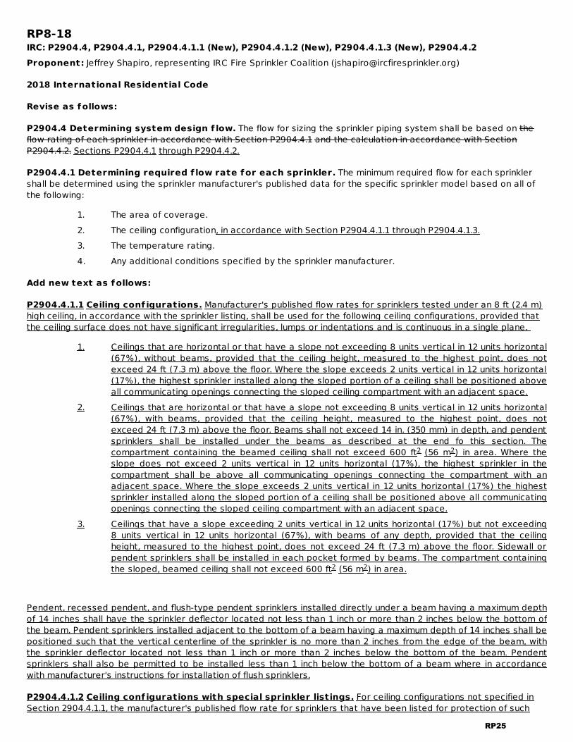
RP8-18IRC: P2904.4, P2904.4.1, P2904.4.1.1 (New), P2904.4.1.2 (New), P2904.4.1.3 (New), P2904.4.2Proponent: Jeffrey Shapiro, representing IRC Fire Sprinkler Coalition ([email protected])
2018 International Residential Code
Revise as follows:
P2904.4 Determining system design f low. The flow for sizing the sprinkler piping system shall be based on theflow rating of each sprinkler in accordance with Section P2904.4.1 and the calculation in accordance with SectionP2904.4.2. Sections P2904.4.1 through P2904.4.2.
P2904.4.1 Determining required f low rate for each sprinkler. The minimum required flow for each sprinklershall be determined using the sprinkler manufacturer's published data for the specific sprinkler model based on all ofthe following:
1. The area of coverage.2. The ceiling configuration, in accordance with Section P2904.4.1.1 through P2904.4.1.3.3. The temperature rating.4. Any additional conditions specified by the sprinkler manufacturer.
Add new text as follows:
P2904.4.1.1 Ceiling conf igurations. Manufacturer's published flow rates for sprinklers tested under an 8 ft (2.4 m)high ceiling, in accordance with the sprinkler listing, shall be used for the following ceiling configurations, provided thatthe ceiling surface does not have significant irregularities, lumps or indentations and is continuous in a single plane.
1. Ceilings that are horizontal or that have a slope not exceeding 8 units vertical in 12 units horizontal(67%), without beams, provided that the ceiling height, measured to the highest point, does notexceed 24 ft (7.3 m) above the floor. Where the slope exceeds 2 units vertical in 12 units horizontal(17%), the highest sprinkler installed along the sloped portion of a ceiling shall be positioned aboveall communicating openings connecting the sloped ceiling compartment with an adjacent space.
2. Ceilings that are horizontal or that have a slope not exceeding 8 units vertical in 12 units horizontal(67%), with beams, provided that the ceiling height, measured to the highest point, does notexceed 24 ft (7.3 m) above the floor. Beams shall not exceed 14 in. (350 mm) in depth, and pendentsprinklers shall be installed under the beams as described at the end fo this section. Thecompartment containing the beamed ceiling shall not exceed 600 ft (56 m ) in area. Where theslope does not exceed 2 units vertical in 12 units horizontal (17%), the highest sprinkler in thecompartment shall be above all communicating openings connecting the compartment with anadjacent space. Where the slope exceeds 2 units vertical in 12 units horizontal (17%) the highestsprinkler installed along the sloped portion of a ceiling shall be positioned above all communicatingopenings connecting the sloped ceiling compartment with an adjacent space.
3. Ceilings that have a slope exceeding 2 units vertical in 12 units horizontal (17%) but not exceeding8 units vertical in 12 units horizontal (67%), with beams of any depth, provided that the ceilingheight, measured to the highest point, does not exceed 24 ft (7.3 m) above the floor. Sidewall orpendent sprinklers shall be installed in each pocket formed by beams. The compartment containingthe sloped, beamed ceiling shall not exceed 600 ft (56 m ) in area.
Pendent, recessed pendent, and flush-type pendent sprinklers installed directly under a beam having a maximum depthof 14 inches shall have the sprinkler deflector located not less than 1 inch or more than 2 inches below the bottom ofthe beam. Pendent sprinklers installed adjacent to the bottom of a beam having a maximum depth of 14 inches shall bepositioned such that the vertical centerline of the sprinkler is no more than 2 inches from the edge of the beam, withthe sprinkler deflector located not less than 1 inch or more than 2 inches below the bottom of the beam. Pendentsprinklers shall also be permitted to be installed less than 1 inch below the bottom of a beam where in accordancewith manufacturer's instructions for installation of flush sprinklers.
P2904.4.1.2 Ceiling conf igurations with special sprinkler listings. For ceiling configurations not specified inSection 2904.4.1.1, the manufacturer's published flow rate for sprinklers that have been listed for protection of such
2 2
2 2
RP25

configurations shall be used.
P2904.4.1.3 Other Ceiling Conf igurations. For ceiling configurations not addressed by Sections P2904.4.1.1 orP2904.4.1.2, the flow rate shall be subject to approval by the fire code official.
Revise as follows:
P2904.4.2 System design f low rate. The design flow rate for the system shall be based on the following:
1. The design flow rate for a room having only one sprinkler shall be the flow rate required for thatsprinkler, as determined by Section P2904.4.1.
2. The design flow rate for a room having two or more sprinklers and a ceiling configuration specifiedin Section P2904.4.1.1 shall be determined by identifying the sprinkler in that room with the highestrequired flow rate, based on Section P2904.4.1, and multiplying that flow rate by 2.
3. Where the sprinkler manufacturer specifies different criteria for ceiling configurations that are notsmooth, flat and horizontal, the required The design flow rate for that room shall comply with thesprinkler a room having two or more sprinklers and a ceiling configuration covered by SectionP2904.4.1.2 shall be in accordance with the manufacturer's instructions.
4. The design flow rate for a room having two or more sprinklers and a ceiling configuration coveredby Section P2904.4.1.3 shall be subject to approval by the fire code official.
5. The design flow rate for the sprinkler system shall be the flow required by the room with the largestflow rate, based on Items 1 , 2 and 3 through 4.
6. For the purpose of this section, it shall be permissible to reduce the design flow rate for a room bysubdividing the space into two or more rooms, where each room is evaluated separately withrespect to the required design flow rate. Each room shall be bounded by walls and a ceiling.Openings in walls shall have a lintel not less than 8 inches (203 mm) in depth and each lintel shallform a solid barrier between the ceiling and the top of the opening.
Reason:These revisions are intended to correlate with NFPA 13D and current installation practices for residential sprinklersprotecting spaces with sloped and/or beamed ceilings.The current Section P2904.4.2 (3) sends the user to the manufacturer’s data sheets for special design informationrelated to sloped and/or beamed ceilings, but data sheets for most residential sprinklers no longer provide guidancefor these conditions. A 2010 Fire Protection Research Foundation study helped to standardize sprinkler protectioncriteria for ceilings with slopes and beams by determining that many sloped and beamed ceilings can be sufficientlyprotected using the same design criteria that apply to horizontal ceilings. This prompted NFPA to add model designcriteria to their sprinkler standards and manufacturers are now amending cut sheets to delete criteria for ceilingconfigurations that are covered by NFPA's standards. Without this revision to Section P2904, the IRC will no longerprovide sufficient guidance for protection of sloped or beamed ceilings, and that could be improperly interpreted asonly allowing smooth, flat, horizontal ceiling configurations in sprinklered dwellings. Cost ImpactThe code change proposal will decrease the cost of construction .The sprinkler rules in the IRC, as written, would not allow for sloped ceilings which made the installation of sprinklersystems much more costly than need be.Internal ID: 421
RP26

RP9-18IRC: TABLE P2904.6.2(2)Proponent: Jeffrey Shapiro, representing IRC Fire Sprinkler Coalition ([email protected])
2018 International Residential Code
Revise as follows:
RP27

TABLE P2904.6.2(2)MINIMUM WATER METER PRESSURE LOSS (PLm)a
FLOW RATE(gallons per minute, gpm)
/ -INCH METER PRESSURELOSS(pounds per square inch, psi)
/ -INCH METER PRESSURELESS(pounds per square inch, psi)
1-INCH METER PRESSURELOSS(pounds per square inch, psi)
8 23 13 110 3 13 112 4 13 114 56 25 116 7 36 118 9 47 1220 11 49 22223 NP14 511 2324 NP 5 226 NP18 614 2328 NP 6 23031 NP26 722 243239 NP38 735 3634 NP 8 33652 NP 8NP 310
b5 8 3 4
RP28

For SI: 1 inch = 25.4 mm, 1 pound per square inch = 6.895 kPa, 1 gallon per minute = 0.063 L/s.NP = Not permitted unless the actual water meter pressure loss is known.
a. Table P2904.6.2(2) establishes conservative values for water meter pressure loss or installationswhere the water meter loss is unknown. Where the actual water meter pressure loss isknownpublished and available from the meter manufacturer, P shall be the actual loss.publishedpressure loss for the selected meter.
b. Flow rate from Section P2904.4.2. Add 5 gpm to the flow rate required by Section P2904.4.2 wherethe water service pipe supplies more than one dwelling.
Reason:This proposal revises the water meter table in the IRC to better correlate with the water meter table in NFPA 13D,which was updated in the 2013 edition based on research that was published in an Fire Protection ResearchFoundation Report titled, " Residential Fire Sprinklers - Water Usage and Water Meter performance Study" in 2011. Therevised IRC table will include NFPA 13D correlated values for 5/8-inch, 3/4-inch and 1-inch meters, and it retains entriesfor flows less than 18 gpm, which have been adjusted to reflect findings from the Fire Protection Research Foundationstudy. NFPA 13D does not include these lesser flows, but the IRC has always included them since low-flow system arean option for affordable housing. This proposal does not add values for 1 1/2-inch and 2-inch meters, which areincluded in NFPA 13D, because these meter sizes are excessive and unnecessary for flow demands associated withhome fire sprinkler systems. Including them in the table could be taken as a basis of validation for water purveyorslooking to justify local requirements for larger, more expensive meters.Bibliography:http://www.nfpa.org/News-and-Research/Fire-statistics-and-reports/Research-reports/Suppression/Residential-Fire-SprinklersCost ImpactThe code change proposal will not increase or decrease the cost of construction .No expected cost consequences are anticipated to be associated with this proposal in most cases since actual meterpressure loss values are typically available. The prescriptive table values are only included in the code for rareoccasions where actual values cannot be ascertained.Internal ID: 1055
m
RP29
RP10-18IRC: P2905.3 (New)Proponent: Anthony Floyd, City of Scottsdale, representing City of Scottsdale ([email protected])
2018 International Residential Code
Add new text as follows:
P2905.3 Hot water supply to f ixtures. The developed length of hot water piping, from the source of hot water tothe fixtures that require hot water, shall not exceed 50 feet (15 240 mm). Water heaters and recirculating systempiping shall be considered to be sources of hot or tempered water.
Reason:This change adds a new section to limit the hot water supply line length from the source of hot water to the fixturesthat require hot or tempered water. This provision is replicated from existing IPC Section 607.2.Hot water supply lines greater than 50 feet waste water (proportional to pipe size) while occupants wait for hot waterto reach fixtures for bathing, washing and culinary purposes. Even though hot water supply lines are insulated, the hotwater remaining in the lines between demand periods cools down. Limiting the length and consequent volume ofheated water in the supply lines reduce the amount of wasted water and occupant waiting time.Cost ImpactThe code change proposal will not increase or decrease the cost of construction .Cost is based on proximity of hot water source to point of use.Internal ID: 552
RP30
RP11-18IRC: P2906.21Proponent: William Chapin, Professional Code Consulting, LLC, representing Professional Code Consulting, LLC([email protected])
2018 International Residential Code
Revise as follows:
P2906.21 Push-f it joints. Push-fit joints shall be used only on copper-tube-size outside diameter dimensionedCPVC, PEX, PE-RT, and copper tubing. Push-fit joints shall conform to ASSE 1061 and shall be installed in accordancewith the manufacturer's instructions.
Reason:Table P2906.6 lists ASSE 1061 fittings as acceptable to be used with polyethylene of raised temperature (PE-RT)plastic tubing. ASSE 1061 does contain testing requirements for use with PE-RT tubing. Cost ImpactThe code change proposal will not increase or decrease the cost of construction .This proposal is only a clarification as Table P2906.6 already indicates ASSE 1061 fittings for PE-RT tubing.Internal ID: 1750
RP31

NSF NSF International789 N. Dixboro Road
Ann Arbor MI 48105
RP12-18IRC: P2909.1, 44Proponent: Jeremy Brown, NSF International, representing NSF International ([email protected])
2018 International Residential Code
Revise as follows:
P2909.1 Design.. Drinking water treatment units shall meet the requirements of NSF42, NSF 44, NSF 53, NSF 60 62 orCSA B483.1.
Add new standard(s) follows:
62-2015:Drinking Water Distillation Systems
Reason:The current text of the IRC references an incorrect standard. NSF 60 is Drinking Water Chemicals-Health Effects. Thisis unrelated to Drinking Water Treatment Units. The origin of this standard in this code goes back to 2009 when a proposal to add CSA 483.1 also incorrectly addedNSF 60. It is beleived that the actual intent was to add NSF 62- Drinking Water Distillation Systems. NSF 62 is an appropriate drinking water treatment technology and this is the American National Standard for thistechnology. This standard is already referenced in the International Plumbing Code in the corresponding section 611.1with the same language. This standard establishes minimum materials, design and construction, and performance requirements for point-of-useand point-of-entry drinking water distillation systems and the components used in these systems. Distillation systemscovered by this standard are designed to reduce specific chemical contaminants from potable drinking water supplies.Systems covered under this standard may also be designed to reduce microbiological contaminants, includingbacteria, viruses, and cysts, from potable drinking water supplies.A copy of NSF 62 was submitted with this code change and may be obtained free of charge by anyone considering thiscode change proposal by emailing [email protected]. Cost ImpactThe code change proposal will not increase or decrease the cost of construction .This creates an additional option for water treatment but does not mandate the use of this technology so is costneutral.
Analysis: The referenced standard, NSF 62-2015, is currently referenced in the 2018 IPC-2015 in a section that iscoordinate in subject matter to the proposed revised section.Internal ID: 144
RP32

RP13-18IRC: P3110 (New), P3110.1 (New), P3110.2 (New), P3110.2.1 (New), P3110.3 (New), P3110.3.1 (New),P3110.3.2 (New), P3110.3.3 (New)Proponent: Jane Malone, American Association of Radon Scientists and Technologists, representing AmericanAssociation of Radon Scientists and Technologists, National Policy Director
2018 International Residential Code
Add new text as follows:
SECTION P3110 SOIL GAS VENT PIPING
P3110.1 Scope. The provisions of this section shall govern the materials, construction, and installation of soil gas ventpipe and connectors.
P3110.2 Soil gas vent pipe. A gas-tight pipe of 3-inch [76 mm] nominal size or larger shall be extended from belowthe slab or crawl space through the interior of the building and exit the roof. The pipe shall be centered in a cylindricalspace which is located in the attic below the roof, is not adjacent to an eave or wall, and has a vertical height of notless than 48 inches [122 cm] and diameter of not less than 21 inches [53 cm]. Materials used shall comply with SectionP3002.
P3110.2.1 Soil gas vent pipe termination. The vent pipe shall terminate vertically upward not less than 12 inches[305 mm] above the roof in a location not less than 10 feet [3048 mm] away from any window, air intake, or otheropening into the conditioned spaces of the building that is less than 2 feet [610 mm] below the exhaust point. The ventpipe shall terminate not less than 10 feet [3048 mm] from window or other opening in adjoining or adjacent buildings.
P3110.3 Soil gas vent pipe connector. A tee fitting or equivalent method shall be installed to secure the soil gasvent pipe to the perforated piping or geotextile matting from which soil gas is collected.
P3110.3.1 Crawl spaces. In a building with a crawl space, a soil gas vent pipe connector shall be installed with notless than 10 feet [3048 mm] of perforated pipe or geotextile matting connected to each of the two horizontal openingsof the connector. The connector and pipe or geotextile matting shall be located below a soil gas membrane complyingwith ASTM Class A, B, or C.
P3110.3.2 Slab-on-grade and basements. In buildings with a basement or slab-on-grade, a soil gas vent pipeconnector of 4-inch [102 mm] nominal diameter shall be installed with not less than 4 feet [1219 mm]of perforated pipeor geotextile matting connected to each of the two horizontal openings of the connector.
P3110.3.3 Drain tile systems. Where an interior drain tile system is present, the two horizontal openings of the soilgas vent pipe connector shall be connected to the drain tile system.
Reason:Chapter 31 governs the piping, tubing and fittings for vents in one- and two-family dwellings. Soil gas vents arecommonly installed by plumbers yet there is no information about soil gas vents in Chapter 31 or elsewhere in theplumbing sections of the IRC. Sections 401 through 701 of ANSI AARST CCAH-2013, Reducing Radon in NewConstruction of One and Two Family Dwellings describe the pipe-related (and other) requirements for soil gas vents.This proposed code change concisely adds the standard’s requirements for such vents, which will ensure that plumbershave the correct information within the IRC plumbing chapter on vents. This change does not add a requirement toprovide a soil gas vent but rather delivers the specification for how to provide one when a building project requiresone. Bibliography:[ANSI AARST CCAH-2013, Reducing Radon in New Construction of One and Two Family Dwellings] [AARST Consortium onRadon Standards] [2013] [http://aarst-nrpp.com/wp/america-national-radon-standards/]Cost ImpactThe code change proposal will not increase or decrease the cost of construction .The provisions are not required for every home. They only apply to homes where the builder or buyer includes soil gasvent pipe.Internal ID: 2287
RP33
RP14-18IRC: P2701.4, P2717.2, P3005.3.5, P3201.1, P3201.2, P3201.3 (New), P3201.4, P3201.3.1, P3201.5, P3201.6,P3201.7, Chapter 44 Proponent: Ronald George, representing Wavin Ltd. ([email protected])
2018 International Residential Code
Add new text as follows:
P3201.3 Non-liquid seal devices. Each non-liquid seal, drainage sealing device shall conform to ASME A112.18.8 andshall be an alternative to a liquid seal type trap. Such devices shall be installed only on 1-1/4 inch (31.8mm) and 1-1/2inch (38.1 mm) tubular drains. Where devices conforming to ASME A112.18.8 are installed on the outlet of food wastedisposers, the devices shall be installed in the vertical, downward flow orientation. These devices shall be protectedfrom back pressure by one of the same approved venting methods as for a liquid seal trap, in accordance with SectionP3101. Non-liquid seal devices shall not be installed on the outlet of a urinal. Where installed, the devices shall beinstalled only in the vertical downward orientation or in horizontal waste branches in accordance with Section P3005.3.The devices shall be installed in accordance with the manufacturer's instructions and shall be accessible.
Revise as follows:
P3201.1 Design of traps.Liquid Seal T raps. Traps relying on a liquid seal shall be of standard design, shall havesmooth uniform internal waterways, shall be self-cleaning and shall not have interior partitions except where integralwith the fixture. Traps shall be constructed of lead, cast iron, copper or copper alloy or approved plastic. Copper orcopper-alloy traps shall be not less than No. 20 gage (0.8 mm) thickness. Solid connections, slip joints and couplingsshall be permitted to be used on the liquid seal type trap inletinlets, liquid seal type trap outletoutlets, or within theliquid seal type trap seal. Slip joints shall be permitted on non-liquid seal devices conforming to Section P3201.3. Trapsand other approved devices having slip-joint connections shall comply with Section P2704.1.
P3201.2 Trap seals.Liquid seal traps. Each fixture trap with a liquid seal shall have a liquid seal of not less than 2inches (51 mm) and not more than 4 inches (102 mm).
Exception: Sealing devices not relying on a liquid seal shall conform to the requirements in Section P3201.3.
P3201.3P3201.4 Liquid Seal T rap setting and protection. Traps Liquid seal traps shall be set level with respectto their water or other liquid seals and shall be protected from freezing. Trap seals shall be protected from siphonage,aspiration or back pressure by an approved system of venting (see Section P3101).
Exception: Sealing devices not relying on a liquid seal shall conform to the requirements in P3201.3.
P3201.4P3201.5 Building traps. Building traps shall be prohibited.
P3201.5P3201.6 Prohibited trap designs. The following types of traps are prohibited:
1. Bell traps.2. Separate fixture traps with interior partitions, except those lavatory traps made of plastic,
stainless steel or other corrosion-resistant material.3. “S” -traps.4. Drum traps.5. Trap designs with moving parts.
Exception: Non-Liquid seal type devices conforming to ASME A112.18.8 and in accordance withSection P3201.3
P3201.6P3201.7 Number of f ixtures per trap. Each plumbing fixture shall be separately trapped by a water sealtrap. trap or a device conforming to the requirements in Section P3201.3. The vertical distance from the fixture outlet tothe trap weir of a liquid seal trap or the inlet of a device meeting the requirements of Section P3201.3 shall not exceed24 inches (610 mm) and the horizontal offset distance of a liquid seal trap shall not exceed 30 inches (762 mm)measured from the centerline of the fixture outlet to the centerline of the inlet of the trap. The height of a clotheswasher standpipe above a trap shall conform to Section P2706.1.2. Fixtures shall not be double trapped.trapped withliquid seal traps and/or devices covered under section P3201.3.
Exceptions:
RP34

ASME American Society of MechanicalEngineers
Two Park AvenueNew York NY 10016-5990
1. Fixtures that have integral traps.2. A single trap or non-liquid seal device shall be permitted to serve two or three like fixtures
limited to kitchen sinks, laundry tubs and lavatories. Such fixtures shall be adjacent to each otherand located in the same room with a continuous waste arrangement. The trap shall be installedat the center fixture where three fixtures are installed. Common trapped fixture outlets shall benot more than 30 inches (762 mm) apart.
3. Connection of a laundry tray waste line into a standpipe for the automatic clothes-washer drainshall be permitted in accordance with Section P2706.1.2.1.
P3002.3.1 Drainage. Drainage fittings shall have a smooth interior waterway of the same diameter as the pipingserved. Fittings shall conform to the type of pipe used. Drainage fittings shall not have ledges, shoulders or reductionsthat can retard or obstruct drainage flow in the piping. Threaded drainage pipe fittings shall be of the recesseddrainage type, black or galvanized. Drainage fittings shall be designed to maintain one-fourth unit vertical in 12 unitshorizontal (2-percent slope) grade. This section shall not be applicable to tubular waste fittings used to convey verticalflow upstream of the trap liquid seal liquid level of a fixture trap or a device conforming to P3201.3.
P3005.2.5 Cleanout size. Cleanouts shall be the same size as the piping served by the cleanout, except cleanoutsfor piping larger than 4 inches (102 mm) need not be larger than 4 inches (102 mm).
Exceptions:
1. A removable P-trap or non-liquid seal type device conforming to Section P3201.3 with slip- orground-joint connections can serve as a cleanout for drain piping that is one size larger than theP-trap tubular drain size.
2. Cleanouts located on stacks can be one size smaller than the stack size.3. The size of cleanouts for cast-iron piping can be in accordance with the referenced standards for
cast iron fittings as indicated in Table P3002.3.
P2704.1 Slip joints. Slip-joint connections shall be installed only for tubular waste piping and only between the trapoutlet tailpiece of a fixture and traps, within traps, on devices conforming to section P3201.3, andon the connection tobetween tubular fixture drains and the drainage piping. piping system. Slip-joint connections shall be made with anapproved elastomeric sealing gasket. Slip-joint connections shall be accessible. Such access shall provide an openingthat is not less than 12 inches (305 mm) in its smallest dimension.
P2717.2 Sink and dishwasher. The combined discharge from a dishwasher and a one- or two-compartment sink,with or without a food-waste disposer, shall be served by a trap or device conforming to section P3201.3 of not lessthan 1 / inches (38 mm) in outside diameter. The dishwasher discharge pipe or tubing shall rise to the underside of thecounter and be fastened or otherwise held in that position before connecting to the head of the food-waste disposeror to a wye fitting in the sink tailpiece.
Add new standard(s) follows:
ASME A112.18.8-2009 (R2014) :In-Line Sanitary Waste Valves for Plumbing Drainage Systems
Reason:ASME standard A112.18.8-2009 (Re-affirmed in 2014) titled: “In-Line Sanitary Waste Valves for Plumbing Drainage” wasdeveloped for sanitary waste devices for use in lieu of p-traps for applications prone to liquid seal loss fromevaporation, siphoning or freezing. They are certified by a third-party testing lab to the testing requirements inthe ASME A112.18.8 Standard listed below. The devices are limited to tubular drains in sizes 1-1/4 inch or 1-1/2 inchoutside diameter (OD). This proposal is to add these non-liquid seal devices as an alternative to liquid seal traps for applications whereevaporation, siphoning or freezing can be a problem. These devices will not fail from evaporation associated with longperiods of non-use as would occur with a water filled p-trap or from negative pressures in the drainage systems thatwould siphon a p-trap, or from freezing which can crack or damage p-traps and p-trap joints. These devices
1 2
RP35

conform to ASME A112.18.8 and they are non-liquid sealing devices not traps or p-traps. They are an alternative to,and a better means of complying with the requirements of preventing sewer gases from entering a building. They fulfillthe same function of a p-trap to not allowing sewer gases to pass into the building. These devices are approved andwidely used in Europe and other international markets.These devices are ideally suited for situations where plumbing fixtures experience only occasional use and canevaporate, like seasonal occupancy dwellings, vacation homes, guest bathrooms, cabins, on bar sinks, in low humidityconditions, or in persistent high temperature conditions. They also offer protection in freezing conditions and wherethere are limited or confined space conditions where a p-trap can conflict with structural or other buildingcomponents. Other common uses for this type of device are in recreational vehicles and ships or boatsThese devices have performed reliably for many years in millions of installations worldwide. They offer a better, morereliable option to a liquid seal p-trap especially in cases where evaporation, siphoning or freezing conditions exist. The testing and performance requirements in the Standard for these devices are very stringent. P-Traps do not have astandard and are not tested. The tests for this device meet and exceed the performance capabilities of a p-trap. Thetests in the standard include the following: 1. Seal materials shall meet various listed standards2. Valve inlet/Outlet dimensions3. Threaded connection dimensions4. Gas-tight seal tests5. Minimum flow rate tests for various tubing sizes/fixtures6. One-way sealing performance tests7. Airway flow rate tests8. Thermal cycling Test9. Long term cyclic fatigue tests10. Grease/lard test11. Resistance to cleaning chemicals and solvents test12. Resistance to household substances and solids tests13. Drop testsThe scope of the ASME A112.18.8 Standard establishes minimum requirements for materials in the construction of thedevices for use as an alternate to tubular p-traps, and prescribes the minimum test requirements for the performanceof the valve. In addition, the standard requires the methods of permanent marking and identification of the product. The standard also states that these devices are not intended to be used for urinals or water closets.Below is an example of the type of valve that complies with the Standard:Cost ImpactThe code change proposal will not increase or decrease the cost of construction .This code change is for a device that is an option to a p-trap. It is not required and therefore, will not cause anincrease in construction. P-traps are still allowed. However, this code change allows for a better performing product asan approved option for areas where evaporation associated with seldom use of a fixture, siphoning or freezing may bean issue.
Analysis: A review of the standard proposed for inclusion in the code, ASME A112.18.8-2009(R2014), with regard to theICC criteria for referenced standards (Section 3.6 of CP#28) will be posted on the ICC website on or before April 2,2018.Internal ID: 887
RP36

RP15-18IRC: TABLE AG101.1Proponent: Larry Gill, IPEX USA LLC, representing IPEX USA LLC ([email protected])
2018 International Residential Code
Revise as follows:
RP37
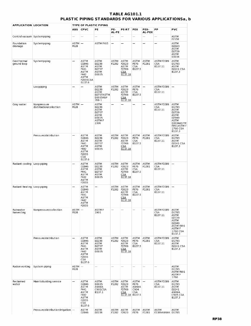
TABLE AG101.1PLASTIC PIPING STANDARDS FOR VARIOUS APPLICATIONSa, b
RP38
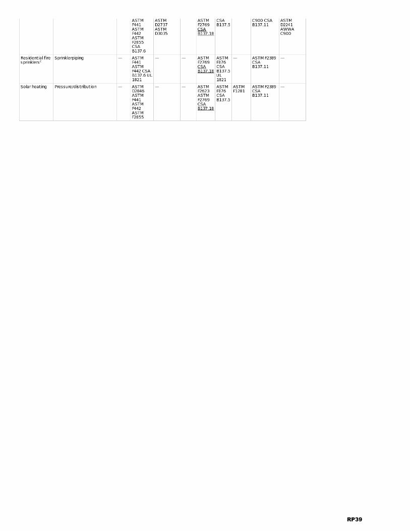
RP39

a. This table indicates manufacturing standards for plastic piping materials that are suitable for use inthe applications indicated. Such applications support green and sustainable building practices. Thesystem designer or the installer of piping shall verify that the piping chosen for an applicationcomplies with local codes and the recommendations of the manufacturer of the piping.
b. Fittings applicable for the piping shall be as recommended by the manufacturer of the piping.c. Piping systems for fire sprinkler applications shall be listed for the application.
Reason:This change is to add CSA B137.18 to the various applications in Table AG 101.1. CSA B137.18 is already included in theI Codes and is referenced in Chapter 44 - Reference Standards of the 2018 IRC.Bibliography:CSA B137.18 Polyethylene of Raised Temperature (PE-RT) Tubing Systems for Pressure ApplicationsCost ImpactThe code change proposal will not increase or decrease the cost of construction .This standard is only another option to choose from. More options generally result in a lowering of the costs ofconstruction.Internal ID: 1045
RP40
RP16-18IRC: Appendix U (New)Proponent: Ed Osann, representing Natural Resources Defense Council ([email protected])
2018 International Residential Code
Add new text as follows:
APPENDIX U Water Efficiency
AU101.1 Scope. This appendix shall apply to:
1. New buildings.2. Additions to existing buildings.3. Alterations to existing buildings.
SECTION AU102 DEFINIT IONS
AU102.1 General. The following words and terms, for purposes of this appendix, shall have the meanings shownherein. Chapter 2 shall be referred to for general definitions.
Add new def inition as follows:
AUTOMATIC. Self-acting, operating by its own mechanism when actuated by some impersonal influence, such as achange in current strength, pressure, temperature, or mechanical configuration.
AUTOMATIC IRRIGATION CONTROLLER. A timing device used to remotely control valves that operate an irrigationsystem.
REGENERATION. The maintenance process that restores a medium in a system so that it can continue to perform itswater treatment function.
RUNOFF. Water that is not absorbed by the soil or landscape to which it is applied and flows from the landscape area.
SUBMETER. A meter installed subordinate to a utility service meter.
WATER SOFTENER. A pressurized water treatment device in which hard water is passed through a bed of cationexchange media (either inorganic or synthetic organic) for the purpose of exchanging calcium and magnesium ions forsodium or potassium ions, thus producing a softened water that is more desirable for laundering, bathing, anddishwashing.
AU103 PLUMBING FIXTURES AND FIXTURE FITT INGS
AU103.1 Maximum f low and water consumption. The maximum water consumption flow rates and quantities forplumbing fixtures and fittings shall be in accordance with Table AU103.1.
RP41
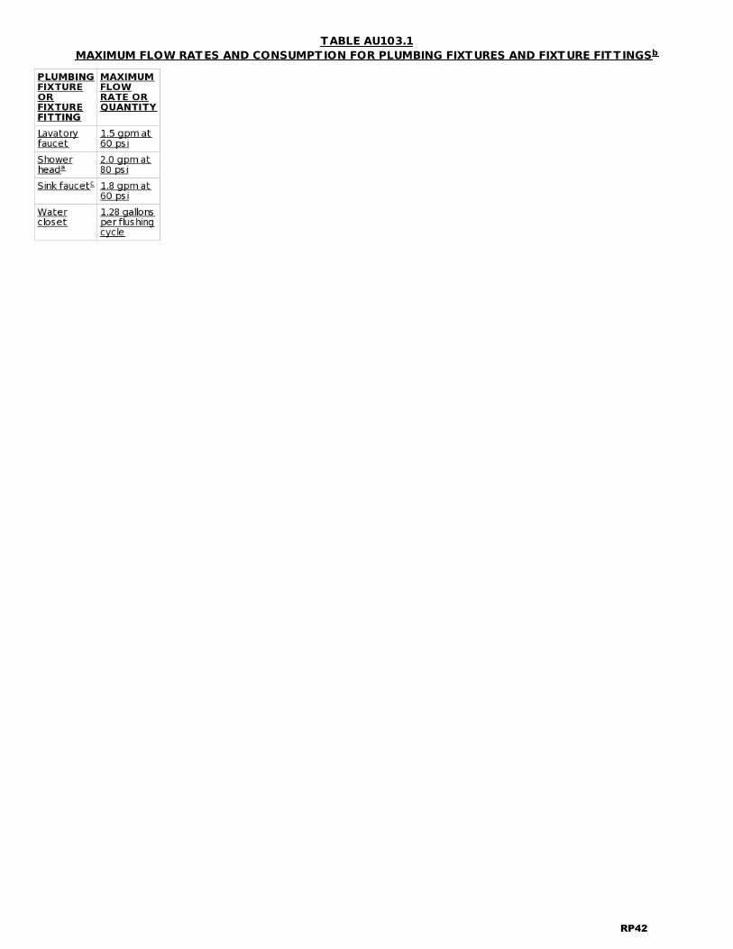
TABLE AU103.1MAXIMUM FLOW RATES AND CONSUMPTION FOR PLUMBING FIXTURES AND FIXTURE FITT INGSb
RP42

For SI: 1 gallon per minute = 3.785 L/m, 1 pound per square inch = 6.895 kPaa. A handheld shower spray shall be considered to be a shower head.b. Consumption tolerances shall be determined from referenced standards.c. Kitchen faucets shall be permitted to have a temporary increase in flow to not exceed 2.2 gpm provided that uponeither the user's physical release of the increased flow activation mechanism or the user's closure of the faucet valve,the faucet reverts to the flow indicated in the table.
AU104 WATER SOFTENERS AND TREATMENT DEVICES
AU104.1 Water sof teners. Water softeners shall be listed and labeled in accordance with NSF 44 and shall complywith Sections AU104.1.1 through AU104.1.3.
AU104.1.1 Demand-initiated regeneration. Water softeners shall be equipped with demand-initiatedregeneration control systems. Such control systems shall automatically initiate the regeneration cycle afterdetermining the depletion, or impending depletion, of softening capacity.
AU104.1.2 Water consumption. Water softeners shall have a maximum water consumption during regeneration of 4gallons per 1,000 grains of hardness removed as measured in accordance with NSF 44.
AU104.1.3 Salt ef f iciency. Water softeners shall have a rated salt efficiency of not less than 4,000 grains of totalhardness exchange per pound of salt, based on sodium chloride equivalency.
AU104.2 Reverse osmosis water treatment systems. Point-of-use reverse osmosis systems shall be equippedwith an automatic shutoff valve that prevents the production of reject water when there is no demand for treatedwater.
AU105 AUTOMATIC IRRIGATION SYSTEMS
AU105.1 Automatic irrigation controllers. Where installed as part of a permanent landscape irrigation system,irrigation controllers shall regulate irrigation based on weather, climatological, or soil moisture status data. Thecontroller shall have an integrated or separate sensor to suspend irrigation events during rainfall.
AU105.2 Misdirection and runof f prohibited. Automatic irrigation systems shall not direct water onto buildingexterior surfaces, foundations, exterior paved surfaces, or adjoining lots. Systems shall not generate runoff.
AU105.3 Landscape water measurement. A submeter shall be installed to separately record the volume of allwater supplied to an outdoor landscape with an irrigated area of 5,000 square feet or greater served by an automaticirrigation system.
Exception: Where a utility service meter is installed to record the volume of all water supplied to the landscapethrough a service connection dedicated to irrigation.
Reason:This proposal adds a short, voluntary appendix to the IRC containing requirements that will enhance the waterefficiency of dwellings subject to the code. The language of this appendix is NOT mandatory unless, and to theextent, specifically referenced in the adopting ordinance or regulation of the jurisdiction.The purpose of the proposal is to offer enhanced water efficiency provisions applicable to one- and two-family homesin code language for consideration by jurisdictions using the IRC. The ICC offers enhanced or "stretch code" provisionsfo r large buildings in the International Green Construction Code (IgCC), but the IgCC does NOT apply to low-riseresidential buildings. The ICC also offers "green" building standards for residential buildings of all sizes in ICC 700, theNational Green Building Standard. However, ICC 700 is a points-based rating system, NOT code language, and thepractices in its chapter on water efficiency are not mandatory. This new appendix will fill this gap, allowing jurisdictionsthat customarily use the IRC the opportunity to consider enhanced water efficiency requirements in familiar codeformat.The proposal is intentionally brief, focusing on three areas of water consumption where enhanced performance criteriaare well-known, and that together are responsible for the great majority of single-family residential water use in nearlyall jurisdictions -- plumbing products, water softening, and landscape irrigation.* Plumbing products: Requirements are based on performance levels established by the US EPA WaterSense Programfor water closets, lavatory faucets, and showerheads, and by the 2016 California Green Building StandardsCode (CalGreen) for kitchen faucets. These provisions are all found in IgCC 2015 as well, in Table 702.1, applicable to
RP43

residential occupancies covered by that code.* Water softeners and treatment devices: These requirements for water use and salt efficiency (an importantconsideration for maintaining water quality and the ability to beneficially recycle municipal wastewater) were allincluded in section 704 of IgCC 2015, and are adopted here for applicability to the one- and two-family homes coveredby the IRC. Water consumption during regeneration and salt efficiency are considered "elective performance claims"under NSF 44, and must be verified by test procedures laid out in section 711 of that standard. The requirements fordemand-initiated regeneration and salt efficiency have been mandatory requirements for all residential watersofteners installed in California since 2002.* Automatic irrigation systems: These requirements are also drawn from the IgCC, where landscape meteringrequirements are specified in section 701.2.1 and other irrigation system requirements are laid out in section 404.1.2. Although the IgCC requires separate metering for irrigated landscapes of all sizes, a less stringent requirement may beappropriate for single-family residences. This proposal limits the metering requirement to residential landscapes of5,000 square feet or more, the threshold of applicability for landscape metering contained in the California Code ofRegulations,Title 23, Chapter 2.7, also known as the Model Water Efficient Landscape Ordinance (MWELO). MWELOalso requires that irrigation controllers in all newly permitted landscape installations in California be either weather-based or soil moisture sensor-based, as required in this proposal. Note that the requirements of section AU105 areonly applicable to permanent irrigation systems with automatic controls, and have no applicability to hose-endsprinklers.Terms that are not otherwise defined in the IRC are included in a definitions section of the appendix. The definitionshave been drawn variously from the IgCC, MWELO, the IAPMO Green Plumbing and Mechanical Code Supplement, andNSF 330.It should be noted that when considering this voluntary appendix, adopting jurisdictions are free to adopt the appendixin its entirety, but may adopt any individual provision of their choosing that they find most relevant to local conditionsand most practical for enforcement. Each element of the proposal stands on its own. The scope of the proposal hasalso been drafted in such a way as to highlight its applicability to project types (new buildings, additions to buildings,and alterations) and allow adopting jurisdictions full latitude to narrow the scope in that regard should they so choose. Each successive year brings new evidence of the impacts of our changing climate, and significant among these impactsare greater extremes and frequency of both droughts and floods. The hydrological record of the last 100 years hasbecome less useful as a predictor of water supply reliability. Few can doubt that efficient water use will become evenmore important in the decades ahead than it is today. Residential water use typically constitutes 60 to 65% of allpublicly supplied drinking water, and the majority of residential use is found in single-family homes. For all thesereasons, the IRC would be made more valuable to jurisdictions throughout the country if it included enhanced waterefficiency criteria in clear code language for voluntary adoption.Bibliography:American Water Works Association/Raftelis Financial Consultants Inc., 2016 Water and Wastewater Rate SurveyICC-ES Water Efficient Plumbing Fixtures -- http://www.icc-es.org/News/Articles/High-efficiencyPlumbingFixtures.pdfPlumbing Manufacturers International, Water Efficiency Overview -- www.safeplumbing.org/water-efficiencyNational Association of Homebuilders, ICC/ASHRAE 700-2015, National Green Building StandardNSF International, NSF/ANSI 44-2016, Residential Cation Exchange Water SoftenersNSF International, NSF/ANSI 330-2015, Glossary of Drinking Water Treatment Unit TerminologyInternational Association of Plumbing and Mechanical Officials, 2015 Green Plumbing & Mechanical Code SupplementCalifornia Department of Water Resources, Model Water Efficient Landscape Ordinance , California Code of Regulations,Title 23, Chapter 2.7, www.water.ca.gov/wateruseefficiency/landscapeordinance/docs/Title 23 extract - Official CCRpages.pdfCalifornia Energy Commission, "Staff Analysis of Water Efficiency Standards for Showerheads," Docket Number 15-AARR-05, p. 13, August 7, 2015, http://docketpublic.energy.ca.gov/PublicDocuments/15-AAER-05/TN205654_20150807T151426_Staff_Analysis_Of_Water_Efficiency_Standards_For_Showerheads.pdfCalifornia Energy Commission, "Staff Analysis of Lavatory Faucet Appliance Standards," Docket Number 15-AAER-05, July24, 2015, http://docketpublic.energy.ca.gov/PublicDocuments/15-AAER-05/TN205513_20150724T152718_Staff_Analysis_of_Lavatory_Faucet_Appliance_Standards.pdfCalifornia Legislative Information, California Health and Safety Code, §§ 116775-116795US Environmental Protection Agency, WaterSense Program, www.epa.gov/watersense/technical-specificationsCost ImpactThe code change proposal will not increase or decrease the cost of construction .
RP44

The proposal offers enhanced water efficiency specifications for voluntary adoption by jurisdictions using the IRC. Assuch, there is no general impact on users of the IRC.The content of this voluntary appendix establishes enhanced efficiency criteria for plumbing products, water softeners,and certain landscape irrigation equipment. Regarding plumbing products, products are widely available from multiple manufacturers. Based on US EPAWaterSense product listings, as of September 2017 there are over 3,100 models of tank-type toilets, over 15,000models of lavatory faucets, and nearly 6,000 models of showerheads that meet the criteria in this proposal. Althoughprices for plumbing products vary widely, based on considerations of style, color, and trim, there is no price premiumattached to higher water use efficiency per se. See, for example, the staff reports of the California Energy Commissionon standards for lavatory faucets and showerheads that found no price premium for products performing at the levelproposed in this voluntary appendix. Regarding water softeners, costs vary widely, but much of this difference is due to capacity, rather than efficiency ofperformance. The key criteria in this proposal have been statewide requirements for residential water softenersin California since 2002. As such, compliant products are widely available from multiple manufacturers. By way ofillustration, as of this writing, the least expensive residential cation exchange water softener now available from Lowesfully complies with all criteria in this proposal (http://pdf.lowes.com/installationguides/090259891214_install.pdf), asdoes the least expensive cation exchange water softener available from Home Depot(https://www.homedepot.com/b/Kitchen-Water-Filters-Water-Softeners/N-5yc1vZaq3y/Ntk-semanticsearch/Ntt-water+softener?NCNI-5). Regarding irrigation controllers, prices also vary widely, with a major driver being the number of zones controlled bythe controller. Some 800 models of irrigation controllers have been certified to the WaterSense specification forweather-based irrigation controllers, so supply and choice of compliant products are ample. Smart controllers are nowrequired for all newly permitted landscape installations in California, ensuring continued competitive interest in thisproduct area.The prevailing price differential between a timer-based controller and a smart controller meeting thecriteria of this proposal has been around $100. But several products are on the market that cut this differential in half,and at least one weather-based irrigation controller is now on the market at a price comparable to a timer-basedcontroller. When products meet enhanced criteria for water efficiency, costs are typically recouped by savings on water and/orsewer charges over the life of the product. According to the 2016 Water and Wastewater Rate Survey , over the lastdecade, water charges have annually increased by 5.34 % and wastewater charges have annually increased by 5.98%, far exceeding the annual inflation rate of 2.07 % for that period. These trends are expected to continue,underscoring the cost-effectiveness of installation of water-efficient products.Internal ID: 2264
RP45