Embed Size (px)
Citation preview
ir33 Universale
User manual
electronic controller

3
ENG
ir33 universale +030220801 - rel. 1.0 - 16.04.2008
WARNINGS
CAREL bases the development of its products on decades of experience
in HVAC, on the continuous investments in technological innovations
to products, procedures and strict quality processes with in-circuit and
functional testing on 100% of its products, and on the most innovative
production technology available on the market. CAREL and its subsidiaries
nonetheless cannot guarantee that all the aspects of the product and the
software included with the product respond to the requirements of the fi nal
application, despite the product being developed according to start-of-the-
art techniques. The customer (manufacturer, developer or installer of the fi nal
equipment) accepts all liability and risk relating to the confi guration of the
product in order to reach the expected results in relation to the specifi c fi nal
installation and/or equipment. CAREL may, based on specifi c agreements, acts
as a consultant for the positive commissioning of the fi nal unit/application,
however in no case does it accept liability for the correct operation of the fi nal
equipment/system.
The CAREL product is a state-of-the-art product, whose operation is specifi ed
in the technical documentation supplied with the product or can be
downloaded, even prior to purchase, from the website www.carel.com.
Each CAREL product, in relation to its advanced level of technology, requires
setup / confi guration / programming / commissioning to be able to operate
in the best possible way for the specifi c application. The failure to complete
such operations, which are required/indicated in the user manual, may cause
the fi nal product to malfunction; CAREL accepts no liability in such cases.
Only qualifi ed personnel may install or carry out technical service on the
product.
The customer must only use the product in the manner described in the
documentation relating to the product.
In addition to observing any further warnings described in this manual, the
following warnings must be heeded for all CAREL products:
prevent the electronic circuits from getting wet. Rain, humidity and all • types of liquids or condensate contain corrosive minerals that may damage
the electronic circuits. In any case, the product should be used or stored
in environments that comply with the temperature and humidity limits
specifi ed in the manual;
do not install the device in particularly hot environments. Too high • temperatures may reduce the life of electronic devices, damage them and
deform or melt the plastic parts. In any case, the product should be used
or stored in environments that comply with the temperature and humidity
limits specifi ed in the manual;
do not attempt to open the device in any way other than described in the • manual;
do not drop, hit or shake the device, as the internal circuits and mechanisms • may be irreparably damaged;
do not use corrosive chemicals, solvents or aggressive detergents to clean • the device;
do not use the product for applications other than those specifi ed in the • technical manual.
All of the above suggestions likewise apply to the controllers, serial boards,
programming keys or any other accessory in the CAREL product portfolio.
CAREL adopts a policy of continual development. Consequently, CAREL
reserves the right to make changes and improvements to any product
described in this document without prior warning.
The technical specifi cations shown in the manual may be changed without
prior warning.
The liability of CAREL in relation to its products is specifi ed in the CAREL general
contract conditions, available on the website www.carel.com and/or by
specifi c agreements with customers; specifi cally, to the extent where allowed
by applicable legislation, in no case will CAREL, its employees or subsidiaries
be liable for any lost earnings or sales, losses of data and information, costs of
replacement goods or services, damage to things or people, downtime or any
direct, indirect, incidental, actual, punitive, exemplary, special or consequential
damage of any kind whatsoever, whether contractual, extra-contractual or
due to negligence, or any other liabilities deriving from the installation, use or
impossibility to use the product, even if CAREL or its subsidiaries are warned
of the possibility of such damage.
DISPOSAL
The product is made from metal parts and plastic parts.
In reference to European Union directive 2002/96/EC issued on 27 January
2003 and the related national legislation, please note that:
WEEE cannot be disposed of as municipal waste and such waste must be 1.
collected and disposed of separately;
the public or private waste collection systems defi ned by local legislation 2.
must be used. In addition, the equipment can be returned to the distributor
at the end of its working life when buying new equipment.
the equipment may contain hazardous substances: the improper use or 3.
incorrect disposal of such may have negative eff ects on human health and
on the environment;
the symbol (crossed-out wheeled bin) shown on the product or on the 4.
packaging and on the instruction sheet indicates that the equipment has
been introduced onto the market after 13 August 2005 and that it must
be disposed of separately;
in the event of illegal disposal of electrical and electronic waste, the 5.
penalties are specifi ed by local waste disposal legislation.

5
ENG
ir33 universale +030220801 - rel. 1.0 - 16.04.2008
Content
1. INTRODUCTION 7
1.1 Models ................................................................................................................. 71.2 Functions and main characteristics .............................................................. 8
2. INSTALLATION 10
2.1 IR33: panel mounting and dimensions ...................................................... 102.2 DN33: DIN rail mounting and dimensions ............................................... 102.3 IR33 Universal wiring diagrams .................................................................... 112.4 DN33 Universal wiring diagrams ................................................................ 122.5 Connection diagrams ..................................................................................... 132.6 Installation ........................................................................................................ 142.7 Programming key (copy set-up).................................................................. 14
3. USER INTERFACE 15
3.1 Display ............................................................................................................... 153.2 Keypad ............................................................................................................. 163.3 Programming ................................................................................................... 163.4 Example: setting the current date/time and the on/off times .................... 183.5 Using the remote control (accessory) .........................................................20
4. COMMISSIONING 22
4.1 Confi guration....................................................................................................224.2 Preparing for operation .................................................................................224.3 Switching the controller On/Off ..................................................................22
5. FUNCTIONS 23
5.1 Probes (analogue inputs) ..............................................................................235.2 Standard operating modes (parameters St1,St2,c0,P1,P2,P3) .............235.3 Validity of control parameters (parameters St1,St2,P1,P2,P3) ...............265.4 Selecting the special operating mode ........................................................265.5 Special operating modes ...............................................................................265.6 Additional remarks on special operation ....................................................295.7 Outputs and inputs .........................................................................................30
6. CONTROL 32
6.1 Type of control (parameter c32) ..................................................................326.2 ti_PID, td_PID (parameters c62,c63) ..........................................................326.3 Auto-Tuning (parameter c64) ........................................................................326.4 Operating cycle .................................................................................................336.5 Operation with probe 2 ..................................................................................33
7. TABLE OF PARAMETERS 37
7.1 Variables only accessible via serial connection...........................................40
8. ALARMS 41
8.1 Types of alarms ................................................................................................. 418.2 Alarms with manual reset ............................................................................... 418.3 Display alarm queue ....................................................................................... 418.4 Table of alarms ................................................................................................428.5 Alarm parameters ...........................................................................................42
9. TECHNICAL SPECIFICATIONS AND PRODUCT CODES 44
9.1 Technical specifi cations ..................................................................................449.2 Cleaning the controller ..................................................................................459.3 Product codes ..................................................................................................459.4 Software revisions ...........................................................................................46


7
ENG
ir33 universale +030220801 - rel. 1.0 - 16.04.2008
1. INTRODUCTION
IR33-DN33 Universal is a series of controllers designed for controlling
the temperature in air-conditioning, refrigeration and heating units. The
models diff er according to the type of power supply (115 to 230 Vac or
12 to 24 Vac, 12 to 30 Vdc) and the outputs, which based on the model
may be one, two or four relays, one or four PWM outputs for controlling
external solid state relays (SSR), one or two relays plus one or two 0 to
10 Vdc analogue outputs (AO) respectively. The models described in this
user manual are suitable for controlling the temperature using four types
of probes: NTC, NTC-HT (high temperature), PTC or PT1000. The type of
control can be set as ON/OFF (proportional) or proportional, integral and
derivative (PID). A second probe can be connected for diff erential control
or freecooling/freeheating, or for compensation based on the outside
temperature. The range includes models for panel installation (IR33), with
IP65 index of protection, and for DIN rail mounting (DN33). To simplify
wiring, all the models are fi tted with plug-in terminals. The controllers
can be connected via a network to supervisory and telemaintenance
systems.
The accessories available include:
computer-based programming tool;• remote control for operation and programming;• programming key, with battery;• programming key, with 230 Vac power supply;• RS485 serial card;• RS485 serial card, with possibility of reversing the Rx-Tx terminals;• module for converting the PWM signal to a 0 to 10 Vdc or 4 to 20 mA • analogue signal;
module for converting the PWM signal to an ON/OFF relay signal.•
1.1 ModelsThe following table describes the models and the main characteristics.
IR33-DN33 UNIVERSALTYPE CODE Characteristics
fl ush mount DIN rail mounting
1 relayIR33V7HR20 DN33V7HR20 2 NTC/PTC/PT1000 input, 1 relay, buzzer, IR receiver, 115 to 230VIR33V7HB20 DN33V7HB20 2 NTC/PTC/PT1000 input, 1 relay , buzzer, IR receiver, RTC, 115 to 230VIR33V7LR20 DN33V7LR20 2 NTC/PTC/PT1000 input, 1 relay , buzzer, IR receiver, 12 to 24V
2 relaysIR33W7HR20 DN33W7HR20 2 NTC/PTC/PT1000 input, 2 relays, buzzer, IR receiver, 115 to 230VIR33W7HB20 DN33W7HB20 2 NTC/PTC/PT1000 input, 2 relays, buzzer , IR receiver, RTC, 115 to 230VIR33W7LR20 DN33W7LR20 2 NTC/PTC/PT1000 input, 2 relays, buzzer, IR receiver, 12 to 24V
4 relaysIR33Z7HR20 DN33Z7HR20 2 NTC/PTC/PT1000 input, 4 relays, buzzer, IR receiver, 115 to 230VIR33Z7HB20 DN33Z7HB20 2 NTC/PTC/PT1000 input, 4 relays , buzzer, IR receiver, RTC, 115 to 230VIR33Z7LR20 DN33Z7LR20 2 NTC/PTC/PT1000 input, 4 relays , buzzer, IR receiver, 12 to 24V
4 SSRIR33A7HR20 DN33A7HR20 2 NTC/PTC/PT1000 input, 4 SSR, buzzer, IR receiver, 115 to 230VIR33A7HB20 DN33A7HB20 2 NTC/PTC/PT1000 input, 4 SSR, buzzer, IR receiver, RTC, 115 to 230VIR33A7LR20 DN33A7LR20 2 NTC/PTC/PT1000 input, 4 SSR, buzzer, IR receiver, 12 to 24V
1 SSRIR33D7HR20 - 2 NTC/PTC/PT1000 input, 1 SSR, buzzer, IR receiver, 115 to 230VIR33D7HB20 - 2 NTC/PTC/PT1000 input, 1 SSR, buzzer, IR receiver, RTC, 115 to 230VIR33D7LR20 - 2 NTC/PTC/PT1000 input, 1 SSR, buzzer, IR receiver, 12 to 24V
1 relay +1
0 - 10Vdc
IR33B7HR20 DN33B7HR20 2 NTC/PTC/PT1000 input, 1 relay + 1 AO, buzzer, IR receiver, 115 to 230VIR33B7HB20 DN33B7HB20 2 NTC/PTC/PT1000 input, 1 relay + 1 AO, buzzer, IR receiver, RTC, 115 to 230VIR33B7LR20 DN33B7LR20 2 NTC/PTC/PT1000 input, 1 relay + 1 AO, buzzer, IR receiver, 12 to 24V
2 rel. +2 x
0 -10Vdc
IR33E7HR20 DN33E7HR20 2 NTC/PTC/PT1000 input, 2 relays + 2 AO, buzzer, IR receiver, 115 to 230VIR33E7HB20 DN33E7HB20 2 NTC/PTC/PT1000 input, 2 relays + 2 AO, buzzer, IR receiver, RTC, 115 to 230VIR33E7LR20 DN33E7LR20 2 NTC/PTC/PT1000 input, 2 relays + 2 AO, buzzer, IR receiver, 12 to 24V
Tab. 1. a
RTC = Real Time Clock
Note that the type of outputs can be identifi ed from the code:the fi fth letter V/W/Z corresponds to 1,2,4 relay outputs respectively;• the fi fth letter D/A corresponds to 1 or 4 PWM outputs respectively; • the fi fth letter B/E corresponds to 1 or 2 relays and 1 or 2 x 0 to 10 Vdc • analogue outputs respectively.
The type of power supply can also be identifi ed:the seventh letter H corresponds to the 115 to 230 Vac power supply;• the seventh letter L indicates the 12 to 24 Vac or 12 to 30Vdc power • supply.
8
Fig. 1. a
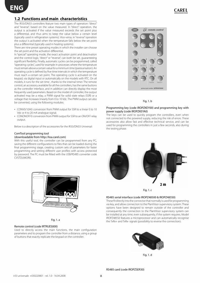
Fig. 1. b
Fig. 1. c
Fig. 1. d
ENG
ir33 universale +030220801 - rel. 1.0 - 16.04.2008
1.2 Functions and main characteristicsThe IR33/DN33 controllers feature two main types of operation: “direct”
and “reverse”, based on the value measured. In “direct” operation, the
output is activated if the value measured exceeds the set point plus
a diff erential, and thus aims to keep the value below a certain level
(typically used in refrigeration systems). Vice-versa, in “reverse” operation
the output is activated when the temperature falls below the set point
plus a diff erential (typically used in heating systems).
There are nine preset operating modes in which the installer can choose
the set point and the activation diff erential.
In “special” operating mode, the exact activation point and deactivation
and the control logic, “direct” or “reverse”, can both be set, guaranteeing
signifi cant fl exibility. Finally, automatic cycles can be programmed, called
“operating cycles”, used for example in processes where the temperature
must remain above a certain value for a minimum time (pasteurisation). An
operating cycle is defi ned by fi ve time intervals in which the temperature
must reach a certain set point. The operating cycle is activated on the
keypad, via digital input or automatically on the models with RTC. On all
models, it runs for the set time , thanks to the internal timer. The remote
control, an accessory available for all the controllers, has the same buttons
as the controller interface, and in addition can directly display the most
frequently used parameters. Based on the model of controller, the output
activated may be a relay, a PWM signal for solid state relays (SSR) or a
voltage that increases linearly from 0 to 10 Vdc. The PWM output can also
be converted, using the following modules:
CONV0/10A0: conversion from PWM output for SSR to a linear 0 to 10 • Vdc or 4 to 20 mA analogue signal;
CONONOFF0: conversion from PWM output for SSR to an ON/OFF relay • output.
Below is a description of the accessories for the IR33/DN33 Universal:
ComTool programming tool (downloadable from http://ksa.carel.com)With this useful tool, the controller can be programmed from any PC,
saving the diff erent confi gurations to fi les that can be loaded during the
fi nal programming stage, creating custom sets of parameters for faster
programming and setting diff erent user profi les with access protected
by password. The PC must be fi tted with the USB/RS485 converter code
CVSTDUMOR0.
Remote control (code IRTRUES000)Used to directly access the main functions, the main confi guration
parameters and to program the controller from a distance, using a group
of buttons that exactly replicate the keypad on the controller.
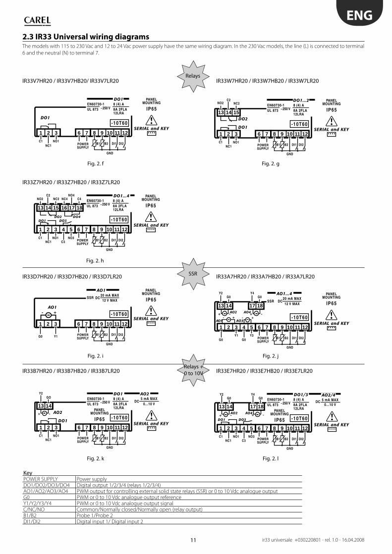
Programming key (code IROPZKEY00) and programming key with power supply (code IROPZKEYA0)The keys can be used to quickly program the controllers, even when
not connected to the powered supply, reducing the risk of errors. These
accessories also allow fast and eff ective technical service, and can be
used for programming the controllers in just a few seconds, also during
the testing phase.
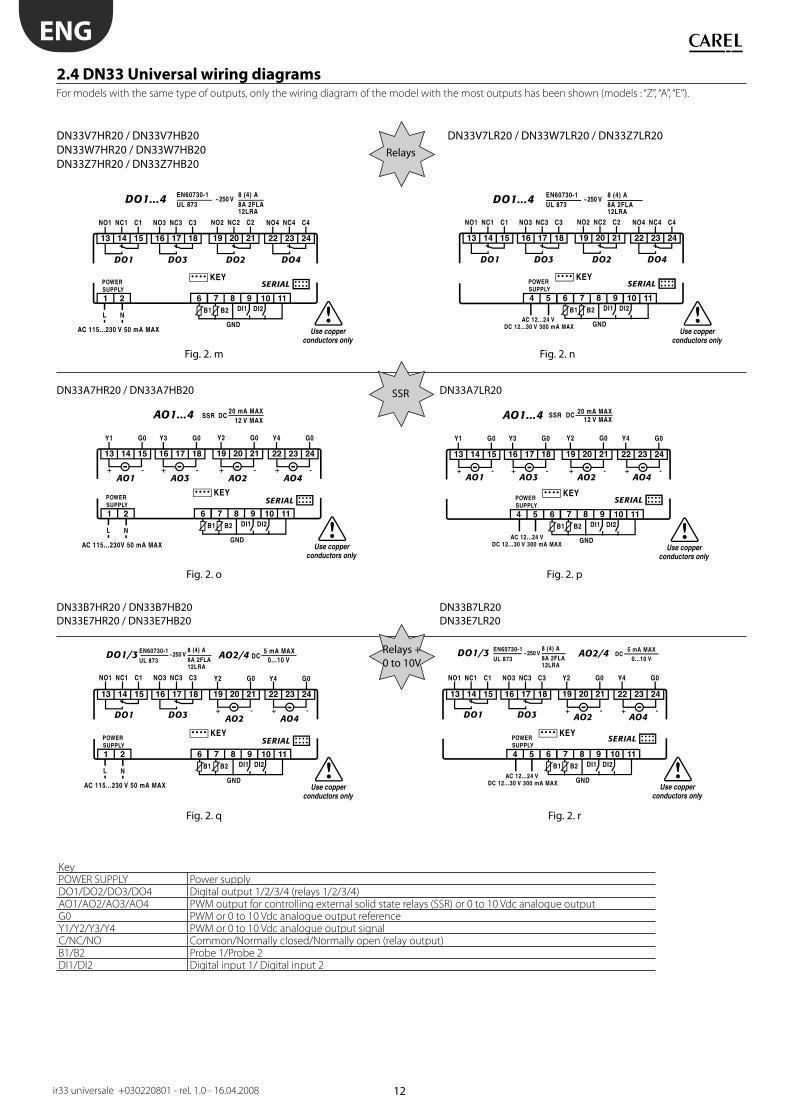
RS485 serial interface (code IROPZ48500 & IROPZ485S0)These fi t directly into the connector that normally is used for programming
via key, and allow connection to the PlantVisor supervisory system. These
options have been designed to remain outside of the controller and
consequently the connection to the PlantVisor supervisory system can
be installed at any time, even subsequently, if the system requires. Model
IROPZ485S0 features a microprocessor and can automatically recognise
the TxRx+ and TxRx- signals (possibility to reverse the connection).
RS485 card (code IROPZSER30)

9
Fig. 1. d
Fig. 1. e
Fig. 1. f
ENG
ir33 universale +030220801 - rel. 1.0 - 16.04.2008
Used to connect the DN33 via the RS485 serial network to the PlantVisor
supervisory system.
Analogue output module (code CONV0/10A0)Converts the PWM signal for solid state relays (SSR) to a standard 0 to
10 Vdc or 4 to 20 mA signal. For models IR/DN33A7**** and IR33D7****
only.
ON/OFF module (code CONVONOFF0)This module converts a PWM signal for solid state relays to an ON/OFF
relay output. Useful when the IR/DN33A7**** or IR33D7**** controller
needs to be used with one or more outputs to control solid state relays,
and at the same time one or more ON/OFF outputs are required for the
control functions or alarms.

10
dima di foraturadrilling template
71x29 mm
34.4
70.579
76.2
80.6
38.6
Fig. 2. a
12
Fig. 2. b
IROPZ48500: Interfaccia scheda seriale RS485Serial board interface RS485
IROPZKEY**: Chiave di programmazioneProgramming key
1
Fig. 2. c
110
70 60
46
Fig. 2. d
IROPZ485S0: Interfaccia schedaseriale RS485intelligenteSmart serial boardinterface RS485
IROPZKEY**: Chiave diprogrammazioneProgramming key
IROPZKEY**: Chiave diprogrammazioneProgramming key
IROPZSER30: Interfaccia scheda seriale RS485Serial board interface RS485
Fig. 2. e
ENG
ir33 universale +030220801 - rel. 1.0 - 16.04.2008
2. INSTALLATION
2.1 IR33: panel mounting and dimensions
2.1.1 IR33 optional connections
2.2 DN33: DIN rail mounting and dimensions
2.2.1 DN33 optional connections
11
6 7SERIAL and KEY
1 2 3 8 9 10 11 12
B1NC1NO1C1
B2 DI1 DI2
DO1
EN60730-1UL 873
PANELMOUNTING
IP65
-10T60
POWERSUPPLY
~250 V8 (4) A8A 2FLA12LRA
DO1
GND
6 7SERIAL and KEY
2 3 8 9 10 11 12
B1
1
G0 Y1 B2 DI1 DI2
AO1- +
12 V MAX20 mA MAX
PANELMOUNTING
IP65
-10T60
POWERSUPPLY
AO1
GND
SSR DC
12 V MAX20 mA MAX
6 7SERIAL and KEY
2 3 4 5 8 9 10 11 12
1413
B1
1
G0Y1
G0Y3
G0Y2
1817
G0Y4
B2 DI1 DI2
AO1
AO2 AO4
AO3
PANELMOUNTING
IP65
-10T60
POWERSUPPLY
AO1...4
- +- +-+-+
GND
SSR DC
6 7SERIAL and KEY
1 2 3 8 9 10 11 12
1413
B1NC1NO1C1
GOY2
B2 DI1
GND
DI2
DO1
AO2
EN60730-1UL 873
PANELMOUNTING
IP65 -10T60
POWERSUPPLY
~250 V8 (4) A
0...10 V8A 2FLA12LRA
5 mA MAXDO1 AO2
-+
DC
6 7SERIAL and KEY
1 2 3 4 5 8 9 10 11 12
B1NC1NO1C1 NO3
C3 B2 DI1 DI2
DO1 DO3
EN60730-1UL 873
PANELMOUNTING
IP65 -10T60
POWERSUPPLY
~250 V8 (4) A8A 2FLA12LRA
DO1/3G0 G0
1413
Y2
1817
Y4
AO2 AO4 -+-+
0...10 V5 mA MAXAO2/4
GND
DC
Fig. 2. f
Fig. 2. i
Fig. 2. k
6 7SERIAL and KEY
1 2 3 8 9 10 11 12
151413
B1NC1NO1C1
NC2NO2C2
B2 DI1 DI2
DO1
DO2
EN60730-1UL 873
PANELMOUNTING
IP65
-10T60
POWERSUPPLY
~250 V8 (4) A8A 2FLA12LRA
DO1...2
GND
Fig. 2. g
Fig. 2. j
Fig. 2. l
6 7SERIAL and KEY
1 2 3 4 5 8 9 10 11 12
151413
B1NC1NO1C1 NO3
C3
NC2NO2C2
181716
NC4NO4
C4
B2 DI1 DI2
DO1DO2 DO4
DO3
EN60730-1UL 873
PANELMOUNTING
IP65
-10T60
POWERSUPPLY
~250 V8 (4) A8A 2FLA12LRA
DO1...4
GND
Fig. 2. h
ENG
ir33 universale +030220801 - rel. 1.0 - 16.04.2008
SSR
2.3 IR33 Universal wiring diagramsThe models with 115 to 230 Vac and 12 to 24 Vac power supply have the same wiring diagram. In the 230 Vac models, the line (L) is connected to terminal
6 and the neutral (N) to terminal 7.
IR33V7HR20 / IR33V7HB20/ IR33V7LR20 IR33W7HR20 / IR33W7HB20 / IR33W7LR20
IR33Z7HR20 / IR33Z7HB20 / IR33Z7LR20
IR33D7HR20 / IR33D7HB20 / IR33D7LR20 IR33A7HR20 / IR33A7HB20 / IR33A7LR20
IR33B7HR20 / IR33B7HB20 / IR33B7LR20 IR33E7HR20 / IR33E7HB20 / IR33E7LR20
KeyPOWER SUPPLY Power supplyDO1/DO2/DO3/DO4 Digital output 1/2/3/4 (relays 1/2/3/4)AO1/AO2/AO3/AO4 PWM output for controlling external solid state relays (SSR) or 0 to 10 Vdc analogue outputG0 PWM or 0 to 10 Vdc analogue output referenceY1/Y2/Y3/Y4 PWM or 0 to 10 Vdc analogue output signalC/NC/NO Common/Normally closed/Normally open (relay output)B1/B2 Probe 1/Probe 2DI1/DI2 Digital input 1/ Digital input 2
Relays
Relays + 0 to 10V
12
-+ -+
Fig. 2. m
Fig. 2. o
Fig. 2. q
Fig. 2. p
Fig. 2. r
Fig. 2. n
ENG
ir33 universale +030220801 - rel. 1.0 - 16.04.2008
SSR
2.4 DN33 Universal wiring diagrams For models with the same type of outputs, only the wiring diagram of the model with the most outputs has been shown (models : “Z”, “A”, “E”).
DN33V7HR20 / DN33V7HB20 DN33V7LR20 / DN33W7LR20 / DN33Z7LR20 DN33W7HR20 / DN33W7HB20 DN33Z7HR20 / DN33Z7HB20
DN33A7HR20 / DN33A7HB20 DN33A7LR20
DN33B7HR20 / DN33B7HB20 DN33B7LR20DN33E7HR20 / DN33E7HB20 DN33E7LR20
KeyPOWER SUPPLY Power supplyDO1/DO2/DO3/DO4 Digital output 1/2/3/4 (relays 1/2/3/4)AO1/AO2/AO3/AO4 PWM output for controlling external solid state relays (SSR) or 0 to 10 Vdc analogue outputG0 PWM or 0 to 10 Vdc analogue output referenceY1/Y2/Y3/Y4 PWM or 0 to 10 Vdc analogue output signalC/NC/NO Common/Normally closed/Normally open (relay output)B1/B2 Probe 1/Probe 2DI1/DI2 Digital input 1/ Digital input 2
Relays
Relays + 0 to 10V
13
-+ -+
Fig. 2. t
1 2 3 4
5 6 7 8
Y+ Y-G0GInput signal
G0 4-20mASignal output
G0 0-10VdcSignal output
CONV0/10A0
24 Vac
230 Vac
Y+ Y-G0GInput signal
1 2 3 4
5 6 7 8
NoOutput
ComNc
CONVONOFF0
Fig. 2. s
ENG
ir33 universale +030220801 - rel. 1.0 - 16.04.2008
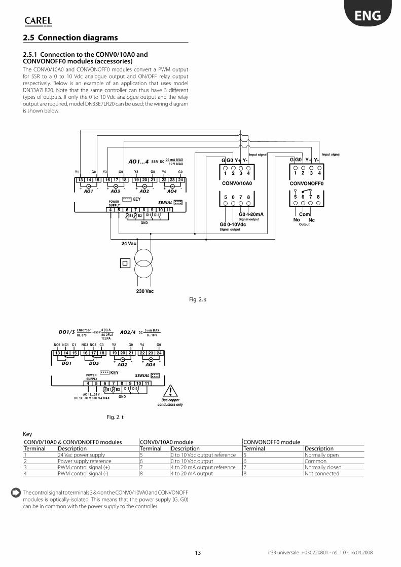
2.5 Connection diagrams
2.5.1 Connection to the CONV0/10A0 and CONVONOFF0 modules (accessories)
The CONV0/10A0 and CONVONOFF0 modules convert a PWM output
for SSR to a 0 to 10 Vdc analogue output and ON/OFF relay output
respectively. Below is an example of an application that uses model
DN33A7LR20. Note that the same controller can thus have 3 diff erent
types of outputs. If only the 0 to 10 Vdc analogue output and the relay
output are required, model DN33E7LR20 can be used; the wiring diagram
is shown below.
KeyCONV0/10A0 & CONVONOFF0 modules CONV0/10A0 module CONVONOFF0 moduleTerminal Description Terminal Description Terminal Description1 24 Vac power supply 5 0 to 10 Vdc output reference 5 Normally open2 Power supply reference 6 0 to 10 Vdc output 6 Common3 PWM control signal (+) 7 4 to 20 mA output reference 7 Normally closed4 PWM control signal (-) 8 4 to 20 mA output 8 Not connected
The control signal to terminals 3 & 4 on the CONV0/10VA0 and CONVONOFF
modules is optically-isolated. This means that the power supply (G, G0)
can be in common with the power supply to the controller.

14
ENG
ir33 universale +030220801 - rel. 1.0 - 16.04.2008
2.6 InstallationTo install the controller, proceed as follows, with reference to the wiring
diagrams:
1) connect the probes and power supply: the probes can be installed
up to a maximum distance of 100 m from the controller, using
shielded cables with a minimum cross-section of 1 mm2. To improve
immunity to disturbance, use probes with shielded cables (connect
only one end of the shield to the earth on the electrical panel).
2) Program the controller: see the chapter “User interface”.
3) Connect the actuators: the actuators should only be connected
after having programmed the controller. Carefully check the
maximum relay capacities, indicated in “technical specifi cations”.
4) Serial network connection: if connection to the supervisor
network is available using the relevant serial cards (IROPZ485*0 for
IR33 & IROPZSER30 for DN33), make sure the system is earthed.
Specifi cally, the secondary of the transformers that
supply the controllers must not be earthed. If connection to a
transformer with earthed secondary winding is required, an
insulating transformer must be installed in between. A series of
controllers can be connected to the same insulating transformer,
nevertheless it is recommended to use a separate insulating
transformer for each controller.
Avoid installing the controller in environments with the following
characteristics:
relative humidity over 90% non-condensing;• heavy vibrations or knocks;• exposure to continuous jets of water;• exposure to aggressive and polluting atmospheric agents (e.g.: sulphur • and ammonia gases, saline mist, smoke) which may cause corrosion
and/or oxidation;
high magnetic and/or radio frequency interference (e.g. do not installe • near transmitting antennas);
exposure to direct sunlight and atmospheric agents in general.•
The following warnings must be observed when connecting the
controllers:
incorrect connection of the power supply may seriously damage the • system;
use cable ends that are suitable for the terminals. Loosen every screw • and fi t the cable end, next tighten the screws and gently pull the
cables to check their tightness;
separate as much as possible (at least 3 cm) the probe and digital • input cables from inductive loads and power cables, to avoid any
electromagnetic disturbance. Never lay power and probe cables in the
same cable conduits (including those for the electrical panels);
do not install the probe cables in the immediate vicinity of power • devices (contactors, circuit breakers or the like). Reduce the length of
the sensor cables as much as possible, and avoid spirals around power
devices;
avoid supplying the controller directly from the main panel power • supply if also supplying power to other devices, such as contactors,
solenoid valves, etc., which require another transformer.
2.7 Programming key (copy set-up)The keys must be connected to the connector (4 pin AMP) fi tted on the
controllers. All the operations can be performed with the controller off .
The functions are selected using the 2 dipswitches, accessed by removing
the battery cover:
load the parameters for a controller onto the key (UPLOAD - Fig. 1);• copy from the key to a controller (DOWNLOAD - Fig. 2);•
UPLOAD DOWNLOAD
The parameters can only be copied between controllers with the same
code. The UPLOAD operation can, however, always be performed.
2.7.1 Copying and downloading the parameters
The following operations are used for the UPLOAD and/or DOWNLOAD
functions, simply by changing the settings of the dipswitches on the
key:
1. open the rear cover on the key and position the 2 dipswitches
according to the desired operation;
2. close the rear cover on the key and plug the key into the connector
on the controller;
3. press the button and check the LED: red for a few seconds, then
green, indicates that the operation was completed correctly.
Other signals or the fl ashing of the LED indicates that problems
have occurred: refer to the table;
4. at the end of the operation, release the button, after a few seconds
the LED goes OFF;
5. remove the key from the controller.
LED signal Error Meaning and solutionRed LED fl ashing Batteries
discharged at
start copy
The batteries are discharged, the copy
operation cannot be performed. Replace
the batteries.Green LED
fl ashing
Batteries
discharged
during copy or
at end of copy
During the copy operation or at the end
of the operation the battery level is low.
Replace the batteries and repeat the
operation.Red/green LED
fl ashing
(orange signal)
Instrument not
compatible
The parameter set-up cannot be copied
as the connected controller model is not
compatible. This error only occurs for the
DOWNLOAD function; check the code of
the controller and run the copy only for
compatible codes.Red and green
LED on
Error in data
being copied
Error in the data being copied. The data
saved on the key are partly/completely
corrupted. Reprogram the key.Red LED on
steady
Data transfer
error
The copy operation was not completed
due to a serious error when transferring
or copying the data. Repeat the
operation, if the problem persists check
the key connections.LEDs off Batteries
disconnected
Check the batteries.

15
Fig. 3. a
ENG
ir33 universale +030220801 - rel. 1.0 - 16.04.2008
3. USER INTERFACE
The front panel contains the display and the keypad, made up of 4
buttons, that, when pressed alone or combined with other buttons, are
used to program the controller.
IR33 Universal front panel
3.1 DisplayThe display shows temperature in range -50 to +150°C.The temperature
is displayed with resolution to the tenths between –19.9 and + 59.9 °C
Alternatively, displays the value of one of the analogue or digital inputs
(see parameter c52). In the event of alarms, the value of the probe
is displayed alternating with the codes of the active alarms. During
programming, it shows the codes and values of the parameters.
ICON FUNCTION NORMAL OPERATION START UP NOTESON OFF BLINK
1 Output 1 Output 1 active Output 1 not active Output 1 request Flashes when activation is delayed or
inhibited by protection times, external
disabling or other procedures in progress.2 Output 2 Output 2 active Output 2 not active Output 2 request See note for output 13 Output 3 Output 3 active Output 3 not active Output 3 request See note for output 14 Output 4 Output 4 active Output 4 not active Output 4 request See note for output 1
ALARM No alarm present Alarms in progress Flashes when alarms are active during
normal operation or when an alarm
is active from external digital input,
immediate or delayed.CLOCK Clock alarm
Operating cycle active
ON if Real Time
Clock present
REVERSE Reverse operation
active
Reverse operation not
active
PWM /0 to 10 Vdc outputs Signals operation of the unit in “reverse”
mode, when at least one relay with
“reverse” operation is active. Flashes if
PWM/0 to 10 Vdc outputs.SERVICE No malfunction Malfunction (e.g. E2PROM
error or probes faulty).
Contact serviceTUNING TUNING AUTO-Tuning function
not enabled
AUTO-Tuning function
enabled
On if the AUTO-Tuning function is active
DIRECT Direct operation
active
Direct operation not
active
PWM /0 to 10 Vdc outputs Signals operation of the unit in “direct”
mode, when at least one relay with “direct”
operation is active. Flashes if PWM/0 to 10
Vdc outputs.
Tab 3.a
The user can select the standard display by suitably setting parameter
c52.
16
Fig. 3.b
Fig. 3.c
ENG
ir33 universale +030220801 - rel. 1.0 - 16.04.2008
3.2 Keypad
Pressing the button alone:
If pressed for more than 5 seconds, accesses the menu for setting the type P parameters (frequent);• Mutes the audible alarm (buzzer) and deactivates the alarm relay;• When editing the parameters, pressed for 5 s, permanently saves the new values of the parameters;• When setting the time and the on/off times returns to the complete list of parameters.• Pressing together with other buttons • If pressed for more than 5 seconds together with Set, accesses the menu for setting the type C parameters (confi guration);• If pressed for more than 5 seconds together with UP, resets any alarms with manual reset (the message ‘rES’ indicates the alarms • have been reset); any alarm delays are reactivated;
Start up
If pressed for more than 5 seconds at start up, activates the procedure for loading the default parameter values.• (UP) Pressing the button alone:
Increases the value of the set point or any other selected parameter• Pressing together with other buttons
If pressed for more than 5 seconds together with Prg/mute, resets any alarms with manual reset (the message ‘rES’ indicates the • alarms have been reset); any alarm delays are reactivated.
(DOWN) Pressing the button alone:
Decreases the value of the set point or any other selected parameter. • In normal operation accesses the display of the second probe and the digital inputs (if enabled).•
Pressing the button alone:
If pressed for more than 1 second displays and/or sets the set point• Pressing together with other buttons • If pressed for more than 5 seconds together with Prg/mute, accesses the menu for setting the type C parameters • (confi guration).
Tab. 3.b
3.3 ProgrammingThe operating parameters can be modifi ed using the front keypad. Access
diff ers depending on the type: set point, frequently-used parameters (P)
and confi guration parameters (C). Access to the confi guration parameters
is protected by a password that prevents unwanted modifi cations or
access by unauthorised persons. The password can be used to access and
set all the control parameters.
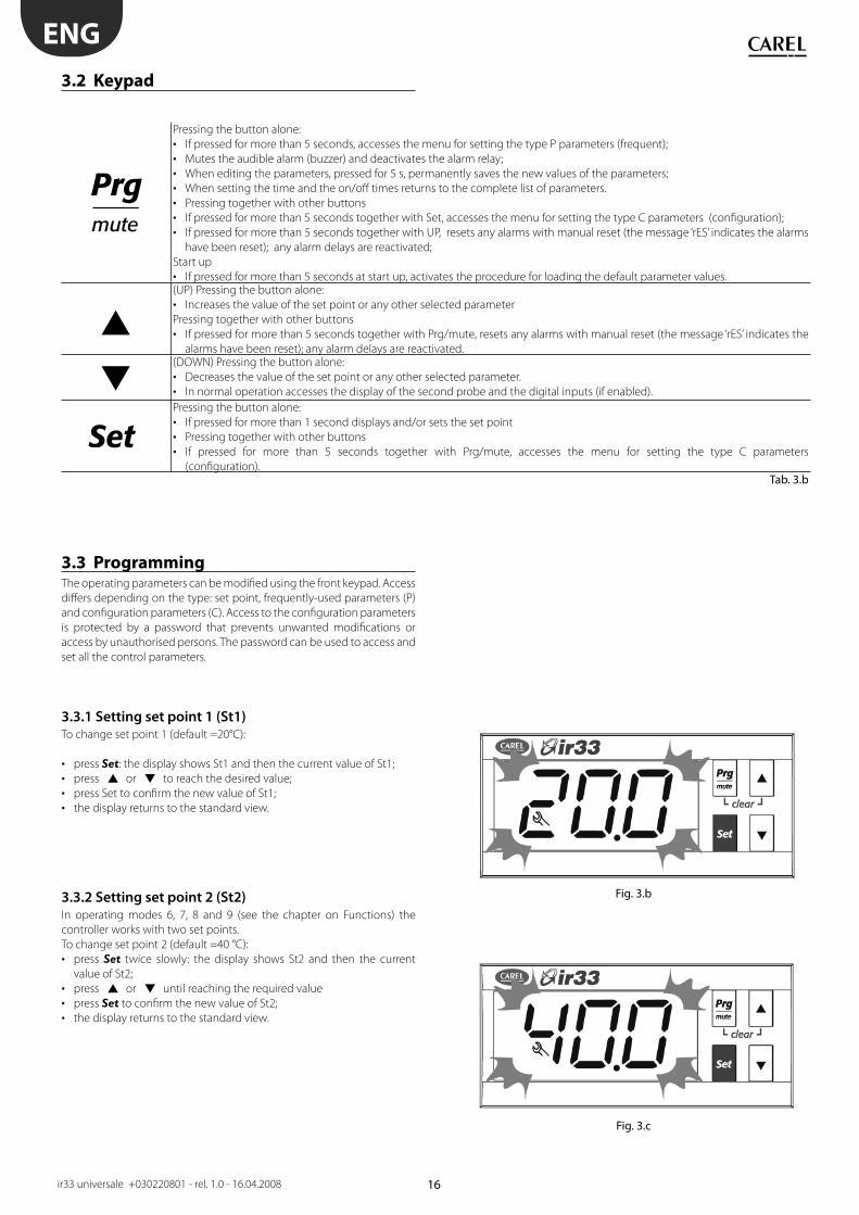
3.3.1 Setting set point 1 (St1)
To change set point 1 (default =20°C):
press • Set: the display shows St1 and then the current value of St1;
press • or to reach the desired value;
press Set to confi rm the new value of St1;• the display returns to the standard view.•
3.3.2 Setting set point 2 (St2)
In operating modes 6, 7, 8 and 9 (see the chapter on Functions) the
controller works with two set points.
To change set point 2 (default =40 °C):
press • Set twice slowly: the display shows St2 and then the current
value of St2;
press • or until reaching the required value
press • Set to confi rm the new value of St2;
the display returns to the standard view.•

17
Fig. 3.d
Fig. 3.e
Fig. 3.f
ENG
ir33 universale +030220801 - rel. 1.0 - 16.04.2008
3.3.3 Setting type P parameters
Type P parameters (frequents) are indicated by a code beginning with the
letter P, followed by one or two numbers.
Press 1. for more than 5 seconds (if an alarm is active, the buzzer
is muted), the display shows the code of the fi rst modifi able type P
parameter, P1;
Press 2. or until reaching the parameter to be modifi ed. When
scrolling, an icon appears on the display representing the category
the parameter belongs to (see the table below and the table of
parameters);
Press 3. Set to display the associated value;
Increase or decrease the value using 4. or respectively, until
reaching the desired value;
Press 5. Set to temporarily save the new value and return to the display
of the parameter code;
Repeat operations from 2) to 5) to set other parameters;6.
To 7. permanently save the new values of the parameters, press for
5 s, thus exiting the parameter setting procedure.
• If no button is pressed for 10s, the display starts fl ashing,
and after 1 minute automatically returns to the standard display.
• To increase the scrolling speed, press and hold the / button
for at least 5 seconds.
3.3.4 Setting type C or d parametersType C or d parameters (confi gurations) are indicated by a code beginning
with the letters C or d respectively, followed by one or two numbers.
1. Press and Set together for more than 5 seconds: the display
shows the number 0;
2. Press or until displaying the password= 77;
3. Confi rm by pressing Set;
4. If the value entered is correct, the fi rst modifi able parameter
c0 will be shown, otherwise the standard display will resume;
5. Press or until reaching the parameter to be modifi ed.
When scrolling, an icon appears on the display representing the
category the parameter belongs to (see the table below and the
table of parameters);
6. Press Set to display the associated value;
7. Increase or decrease the value using or respectively,
until reaching the desired value;
8. Press Set to temporarily save the new value and return to the
display of the parameter code;
9. Repeat operations from 5) to 8) to set other parameters;
10. To permanently save the new values of the parameters, press
for 5 s, thus exiting the parameter setting procedure.
This procedure can be used to access all the control parameters.
PARAMETER CATEGORIESCategory Icon Category IconProgramming Output 2 2
Alarm Output 3 3
PID TUNING Output 4 4Output 1 1 RTC

18
Fig. 3.g
Fig. 3.h
Fig. 3.i
Fig. 3.j
ENG
ir33 universale +030220801 - rel. 1.0 - 16.04.2008
All the modifi cations made to the parameters, temporarily stored in the
RAM, can be cancelled, returning to the standard display by not pressing
any button for 60 seconds.
The values of the clock parameters, however, are saved when entered.
If the controller is powered down before pressing , all the modifi cations
made to the parameters will be lost
In the two parameter setting procedures (P and C), the new values are
only saved after having pressed for 5 seconds. When setting the set
point, the new value is saved after confi rming with Set.
3.4 Example: setting the current date/time and
the on/off timesThis example applies to models fi tted with RTC.
3.4.1 Setting the current date/time
1. Access the type C parameters as described in the corresponding
paragraph;
2. Press the / buttons and select the parent parameter, tc ;
3. Press Set: parameter y is displayed, followed by two digits that
indicate the current year;
4. Press Set and set the value of the current year
(e.g.: 8=2008), press Set again to confi rm;
5. Press to select the next parameter -month -and repeat steps 3
& 4 for the following parameters:
M=month, d=day of the month, u=day of the week
h=hours,m=minutes;
6. To return to the list of main parameters, press and then access
parameters ton and toF (see the following paragraph), or:
7. To save the settings press for 5 seconds and exit the parameter
setting procedure.
3.4.2 Setting the on/off times
1. Access the type C parameters as described in the corresponding
paragraph;
2. Press the / buttons and select the parent parameter, ton
= on time;
3. Press Set parameter d is displayed, followed by one or two digits
that represent the on day, as follows:
0= timed start disabled
1 to 7= Monday to Sunday
8= Monday to Friday
9= Monday to Saturday
10= Saturday & Sunday
11= every day
4. Press Set to confi rm and go to the on time parameters
h/m=hours/minutes;
5. To return to the list of main parameters, press and then access
parameter toF = off time;
6. To save the settings press for 5 seconds and exit the parameter
setting procedure.

19
Fig. 3.k
Fig. 3.l
ENG
ir33 universale +030220801 - rel. 1.0 - 16.04.2008
3.4.3 Setting the default parameters
To set the parameters to the default values:
Power down the controller;•
Press • ;
Power up the controller holding the • button, until the message
“Std” is shown on the display.
This will cancel any changes made and restore the original values set by
the manufacturer.
3.4.4 Alarms with manual reset
The alarms with manual reset can be reset by pressing and p
together for more than 5 seconds.
3.4.5 Activating the operating cycle
The operating cycle activation mode is selected using parameter P70 (see
the chapter on Control). Below is a description of the activation procedure
from the keypad (manual), digital input and RTC (automatic).
3.4.6 Manual activation (P70=1)
During the normal operation of the controller, pressing the button
for 5 seconds displays CL, which indicates “operating cycle”. mode is being
accessed The operating cycle features 5 temperature/time steps, which
need to be set (see the chapter on Control). The operating cycle will be
run and the clock icon will fl ash.
The operating cycle ends automatically when it reaches the fi fth step. To
stop an operating cycle before the end, press the button again for 5
seconds. The message “StP” (stop) will be displayed.
If P70≠1, pressing the button for 5s does not active a procedure, but
rather the display shows “StP” and normal control resumes.
3.4.7 Activation from digital input 1/2 (P70=2)
To activate the operating cycle from digital input 1, set P70=2 and c29=5.
For digital input 2 set P70=2 and c30=5. Connect the selected digital
input to a button (NOT a switch). To activate the operating cycle, briefl y
press the button: this will be run, and the clock icon will fl ash. To stop an
operating cycle before the end, press the button again for 5 seconds.
The message “StP” (stop) will be displayed.
3.4.8 Automatic activation (P70=3)
The automatic activation of an operating cycle is only possible on the
models fi tted with RTC.
To activate an operating cycle automatically:
Set the parameters for the duration of the step and the set point • (P71-P80);
Program the controller automatic on/off times – parameters ton and • toF;
Set parameter P70=3.•
The operating cycle will start automatically when the controller switches
on.
3.4.9 Auto-Tuning activation
See the chapter on Control.
20
Fig. 3.m
Fig. 3.n
Fig. 3.o
ENG
ir33 universale +030220801 - rel. 1.0 - 16.04.2008
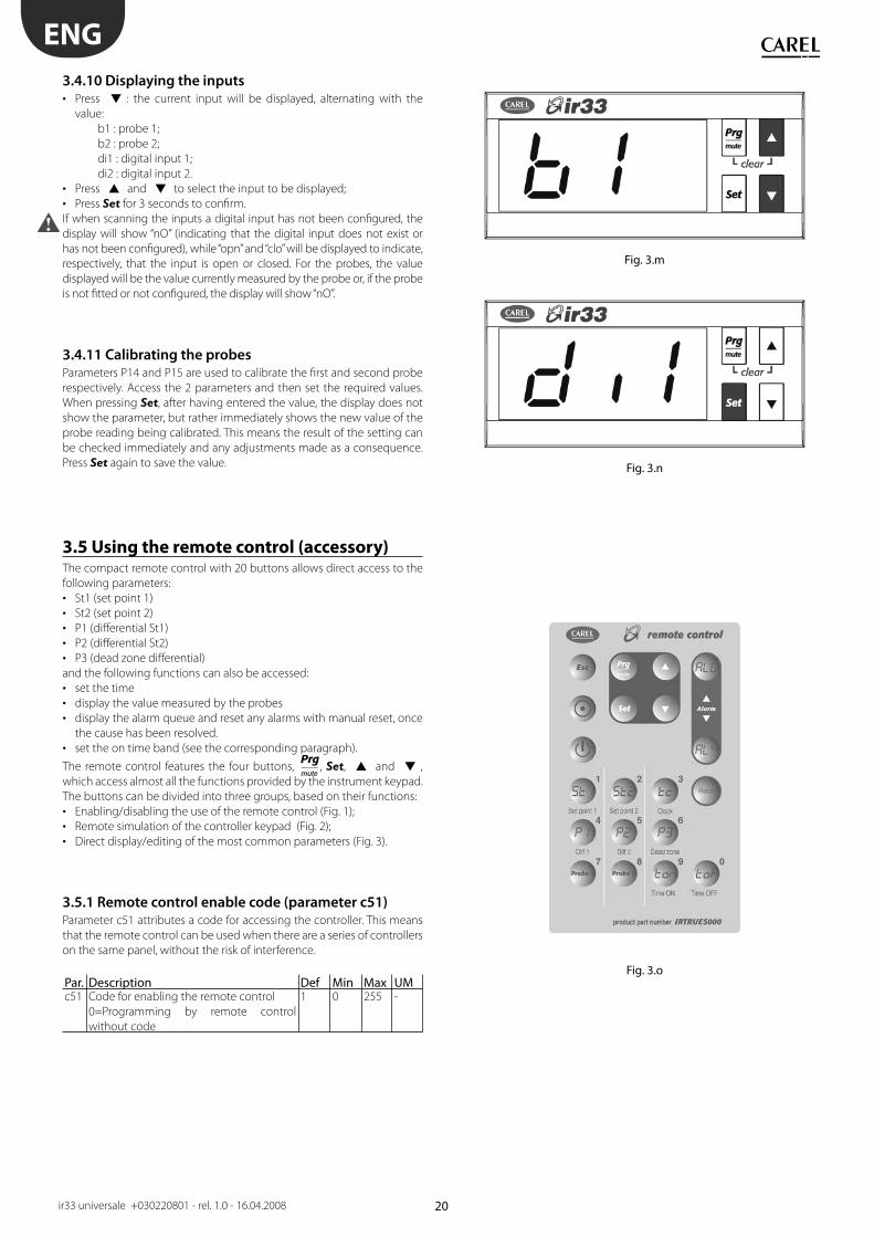
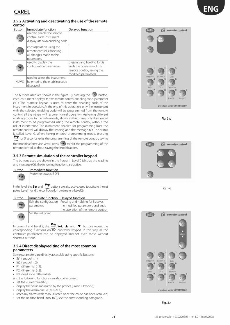
3.4.10 Displaying the inputs
Press • : the current input will be displayed, alternating with the
value:
b1 : probe 1;
b2 : probe 2;
di1 : digital input 1;
di2 : digital input 2.
Press • and to select the input to be displayed;
Press • Set for 3 seconds to confi rm.
If when scanning the inputs a digital input has not been confi gured, the
display will show “nO” (indicating that the digital input does not exist or
has not been confi gured), while “opn” and “clo” will be displayed to indicate,
respectively, that the input is open or closed. For the probes, the value
displayed will be the value currently measured by the probe or, if the probe
is not fi tted or not confi gured, the display will show “nO”.
3.4.11 Calibrating the probes
Parameters P14 and P15 are used to calibrate the fi rst and second probe
respectively. Access the 2 parameters and then set the required values.
When pressing Set, after having entered the value, the display does not
show the parameter, but rather immediately shows the new value of the
probe reading being calibrated. This means the result of the setting can
be checked immediately and any adjustments made as a consequence.
Press Set again to save the value.
3.5 Using the remote control (accessory)The compact remote control with 20 buttons allows direct access to the
following parameters:
St1 (set point 1)• St2 (set point 2)• P1 (diff erential St1)• P2 (diff erential St2)• P3 (dead zone diff erential)•
and the following functions can also be accessed:
set the time• display the value measured by the probes• display the alarm queue and reset any alarms with manual reset, once • the cause has been resolved.
set the on time band (see the corresponding paragraph).•
The remote control features the four buttons, , Set, and ,
which access almost all the functions provided by the instrument keypad.
The buttons can be divided into three groups, based on their functions:
Enabling/disabling the use of the remote control (Fig. 1);• Remote simulation of the controller keypad (Fig. 2);• Direct display/editing of the most common parameters (Fig. 3).•
3.5.1 Remote control enable code (parameter c51)
Parameter c51 attributes a code for accessing the controller. This means
that the remote control can be used when there are a series of controllers
on the same panel, without the risk of interference.
Par. Description Def Min Max UMc51 Code for enabling the remote control
0=Programming by remote control
without code
1 0 255 -
21
Fig. 3.p
Fig. 3.q
Fig. 3.r
ENG
ir33 universale +030220801 - rel. 1.0 - 16.04.2008
3.5.2 Activating and deactivating the use of the remote controlButton Immediate function Delayed function
used to enable the remote
control; each instrument
displays its own enabling code
Esc
ends operation using the
remote control, cancelling
all changes made to the
parametersused to display the
confi guration parameters
pressing and holding for 5s
ends the operation of the
remote control, saving the
modifi ed parameters
NUMS.
used to select the instrument,
by entering the enabling code
displayed.
The buttons used are shown in the fi gure. By pressing the button,
each instrument displays its own remote control enabling code (parameter
c51). The numeric keypad is used to enter the enabling code of the
instrument in question. At the end of this operation, only the instrument
with the selected enabling code will be programmed from the remote
control, all the others will resume normal operation. Assigning diff erent
enabling codes to the instruments, allows, in this phase, only the desired
instrument to be programmed using the remote control, without the
risk of interference. The instrument enabled for programming from the
remote control will display the reading and the message rCt. This status
is called Level 0. When having entered programming mode, pressing
for 5 seconds exits the programming of the remote control, saving
the modifi cations; vice-versa, press Esc to exit the programming of the
remote control, without saving the modifi cations.
3.5.3 Remote simulation of the controller keypad
The buttons used are shown in the fi gure. In Level 0 (display the reading
and message rCt), the following functions are active:
Button Immediate functionMute the buzzer, if ON
In this level, the Set and buttons are also active, used to activate the set
point (Level 1) and the confi guration parameters (Level 2).
Button Immediate function Delayed functionEdit the confi guration
parameters
Pressing and holding for 5s saves
the modifi ed parameters and ends
the operation of the remote control
SetSet the set point
In Levels 1 and Level 2, the , Set, and buttons repeat the
corresponding functions on the controller keypad. In this way, all the
controller parameters can be displayed and set, even those without
shortcut buttons.
3.5.4 Direct display/editing of the most common parameters
Some parameters are directly accessible using specifi c buttons:
St1 ( set point 1);• St2 ( set point 2);• P1 (diff erential St1);• P2 (diff erential St2);• P3 (dead zone diff erential)•
and the following functions can also be accessed:
set the current time(tc);• display the value measured by the probes (Probe1, Probe2);• display the alarm queue (AL0-AL4);• reset any alarms with manual reset, once the cause has been resolved;• set the on time band ( ton, toF), see the corresponding paragraph.•
22
ENG
ir33 universale +030220801 - rel. 1.0 - 16.04.2008
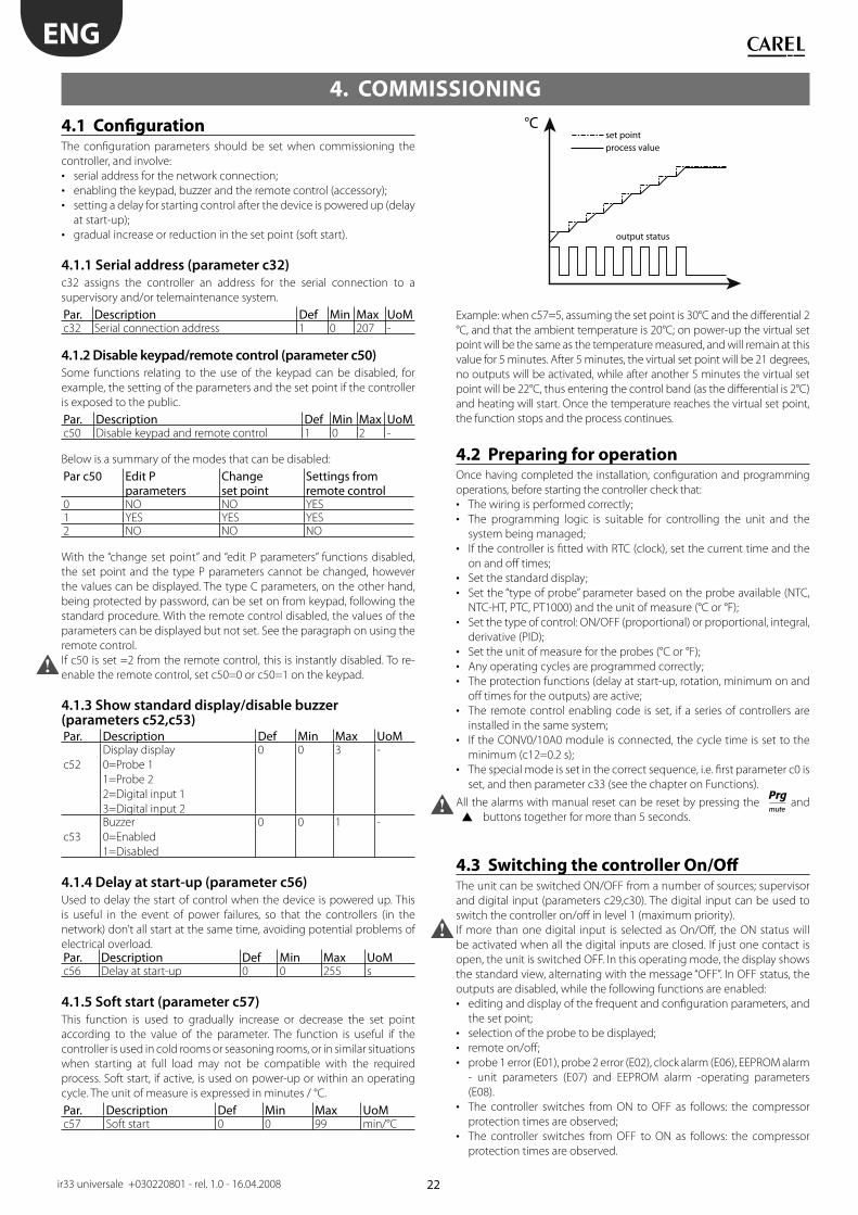
°Cset pointprocess value
output status
4.1 Confi gurationThe confi guration parameters should be set when commissioning the
controller, and involve:
serial address for the network connection;• enabling the keypad, buzzer and the remote control (accessory);• setting a delay for starting control after the device is powered up (delay • at start-up);
gradual increase or reduction in the set point (soft start).•
4.1.1 Serial address (parameter c32)
c32 assigns the controller an address for the serial connection to a
supervisory and/or telemaintenance system.
Par. Description Def Min Max UoMc32 Serial connection address 1 0 207 -
4.1.2 Disable keypad/remote control (parameter c50)
Some functions relating to the use of the keypad can be disabled, for
example, the setting of the parameters and the set point if the controller
is exposed to the public.
Par. Description Def Min Max UoMc50 Disable keypad and remote control 1 0 2 -
Below is a summary of the modes that can be disabled:
Par c50 Edit P parameters
Change set point
Settings fromremote control
0 NO NO YES1 YES YES YES2 NO NO NO
With the “change set point” and “edit P parameters” functions disabled,
the set point and the type P parameters cannot be changed, however
the values can be displayed. The type C parameters, on the other hand,
being protected by password, can be set on from keypad, following the
standard procedure. With the remote control disabled, the values of the
parameters can be displayed but not set. See the paragraph on using the
remote control.
If c50 is set =2 from the remote control, this is instantly disabled. To re-
enable the remote control, set c50=0 or c50=1 on the keypad.
4.1.3 Show standard display/disable buzzer (parameters c52,c53)Par. Description Def Min Max UoM
c52
Display display
0=Probe 1
1=Probe 2
2=Digital input 1
3=Digital input 2
0 0 3 -
c53
Buzzer
0=Enabled
1=Disabled
0 0 1 -
4.1.4 Delay at start-up (parameter c56)
Used to delay the start of control when the device is powered up. This
is useful in the event of power failures, so that the controllers (in the
network) don’t all start at the same time, avoiding potential problems of
electrical overload.Par. Description Def Min Max UoMc56 Delay at start-up 0 0 255 s
4.1.5 Soft start (parameter c57)
This function is used to gradually increase or decrease the set point
according to the value of the parameter. The function is useful if the
controller is used in cold rooms or seasoning rooms, or in similar situations
when starting at full load may not be compatible with the required
process. Soft start, if active, is used on power-up or within an operating
cycle. The unit of measure is expressed in minutes / °C.
Par. Description Def Min Max UoMc57 Soft start 0 0 99 min/°C
Example: when c57=5, assuming the set point is 30°C and the diff erential 2
°C, and that the ambient temperature is 20°C; on power-up the virtual set
point will be the same as the temperature measured, and will remain at this
value for 5 minutes. After 5 minutes, the virtual set point will be 21 degrees,
no outputs will be activated, while after another 5 minutes the virtual set
point will be 22°C, thus entering the control band (as the diff erential is 2°C)
and heating will start. Once the temperature reaches the virtual set point,
the function stops and the process continues.
4.2 Preparing for operationOnce having completed the installation, confi guration and programming
operations, before starting the controller check that:
The wiring is performed correctly;• The programming logic is suitable for controlling the unit and the • system being managed;
If the controller is fi tted with RTC (clock), set the current time and the • on and off times;
Set the standard display;• Set the “type of probe” parameter based on the probe available (NTC, • NTC-HT, PTC, PT1000) and the unit of measure (°C or °F);
Set the type of control: ON/OFF (proportional) or proportional, integral, • derivative (PID);
Set the unit of measure for the probes (°C or °F);• Any operating cycles are programmed correctly;• The protection functions (delay at start-up, rotation, minimum on and • off times for the outputs) are active;
The remote control enabling code is set, if a series of controllers are • installed in the same system;
If the CONV0/10A0 module is connected, the cycle time is set to the • minimum (c12=0.2 s);
The special mode is set in the correct sequence, i.e. fi rst parameter c0 is • set, and then parameter c33 (see the chapter on Functions).
All the alarms with manual reset can be reset by pressing the and
buttons together for more than 5 seconds.
4.3 Switching the controller On/Off The unit can be switched ON/OFF from a number of sources; supervisor
and digital input (parameters c29,c30). The digital input can be used to
switch the controller on/off in level 1 (maximum priority).
If more than one digital input is selected as On/Off , the ON status will
be activated when all the digital inputs are closed. If just one contact is
open, the unit is switched OFF. In this operating mode, the display shows
the standard view, alternating with the message “OFF”. In OFF status, the
outputs are disabled, while the following functions are enabled:
editing and display of the frequent and confi guration parameters, and • the set point;
selection of the probe to be displayed;• remote on/off ;• probe 1 error (E01), probe 2 error (E02), clock alarm (E06), EEPROM alarm • - unit parameters (E07) and EEPROM alarm -operating parameters
(E08).
The controller switches from ON to OFF as follows: the compressor • protection times are observed;
The controller switches from OFF to ON as follows: the compressor • protection times are observed.
4. COMMISSIONING
23
ONOUT1
Mod. V
OFF
St1
B1P1
ONOUT1 OUT2
Mod. W
OFF
St1
B1P1
ONOUT1 OUT2 OUT3 OUT4
Mod. Z
OFF
St1
B1P1
ENG
ir33 universale +030220801 - rel. 1.0 - 16.04.2008
5.1 Probes (analogue inputs)The probe parameters are used to :
set the type of probe• set the off set to correct the probe reading (calibration)• activate a fi lter to stabilise the reading• set the unit of measure shown on the display• enable the second probe and the compensation function•
Par. Description Def Min Max UoMc13 Type of probe
0=NTC standard range (-50T+90°C)
1=NTC enhanced range(-40T+150°C)
2=PTC standard range(-50T+150°C)
3=PT100 standard range(-50T+150°C)
0 0 3 -
P14 Calibration of probe 1 0 -20 20 °C/°FP15 Calibration of probe 2 0 -20 20 °C/°Fc17 Probe disturbance fi lter 4 1 15 -c18 Select temperature unit of measure
0=°C
1=°F
0 0 1 -
Parameter c13 defi nes the type of probe 1 (B1) and any probe 2 (B2).
Parameters P14 and P15, for probe 1 and probe 2 respectively, are used to
correct the temperature measured by the probes indicated on the display,
using an off set: the value assigned to these parameters is in fact added
to (positive value) or subtracted from (negative value) the temperature
measured by the probes. When pressing Set, after having entered the
value, the display does not show the parameter, but rather immediately
shows the new value of the probe reading being calibrated. This means
the result of the setting can be checked immediately and any adjustments
made as a consequence. Press Set again to access the parameter code
and save the value. Parameter c17 defi nes the coeffi cient used to stabilise
the temperature reading. Low values assigned to this parameter allow a
prompt response of the sensor to temperature variations, but the reading
becomes more sensitive to disturbance. High values slow down the
response, but guarantee greater immunity to disturbance, that is, a more
stable and more precise reading.
5.1.1 Second probe (parameter c19)
Par. Description Def Min Max UoMc19 Operation of probe 2
0=not enabled
1=diff erential operation
2=compensation in cooling
3=compensation in heating
4=compensation always active
5=enable logic on absolute set point
6=enable logic on diff . set point
Validity : c0=1 or 2
0 0 6 -
The second probe must be the same type as the fi rst, NTC, NTC-HT, PTC or
PT1000, as set by parameter c13.
For the explanation of the types of control based on parameter c19, see
the chapter on “Control”.
5.2 Standard operating modes (parameters
St1,St2,c0,P1,P2,P3) The controller can operate in 9 diff erent modes, selected by parameter
c0. The basic modes are “direct” and “reverse”. In “direct” mode, the output
is activated if the value measured is greater than the set point plus a
diff erential. In “reverse” mode the output is activated if the temperature is
less than the set point plus a diff erential. The other modes are a combination
of these, with possibility of 2 set points (St1 & St2) and 2 diff erentials (P1 &
P2) based on the mode, “direct” or “reverse”, or the status of digital input
1. Other modes include “dead zone” (P3), “PWM” and “alarm”. The number
of outputs activated depends on the model (V/W/Z=1,2,4 relay outputs,
D/A =1/4 PWM outputs, B/E=1/2 analogue outputs and 1/2 relay outputs).
Selecting the correct operating mode is the fi rst action to be performed
when the default confi guration, i.e. “reverse” operation, is not suitable for
the application in question.
Par. Description Def Min Max UoMSt1 Set point 1 20 c21 c22 °C/°FSt2 Set point 2 40 c23 c24 °C/°Fc0 1=direct
2=reverse
3=dead zone
4=PWM
5=alarm
6=direct/reverse from digital input 1
7=direct: set point & diff erential from
digital input 1
8=reverse: set point & diff erential from
digital input 1
9=direct & reverse with separate set p.
2 1 9 -
P1 Set point diff erential 1 2 0.1 50 °C/°FP2 Set point diff erential 2 2 0.1 50 °C/°FP3 Dead zone diff erential 2 0 20 °C/°Fc21 Minimum value of set point 1 -50 -50 c22 °C/°Fc22 Maximum value of set point 1 60 c21 150 °C/°Fc23 Minimum value of set point 2 -50 -50 c24 °C/°Fc24 Maximum value of set point 2 60 c23 150 °C/°F
To be able to set c0, the value of c33 must be 0. If c33=1, changing c0
has no eff ect.
For the mode set to become immediately operational, the controller
needs to be switched off an on again. Otherwise correct operation is not
guaranteed.
The meaning of parameters P1 & P2 changes according to the operating
mode selected. Fore example, in modes 1 & 2 the diff erential is always
P1. P2, on the other hand, is the “reverse” diff erential in mode 6 and the
“direct” diff erential in mode 9.
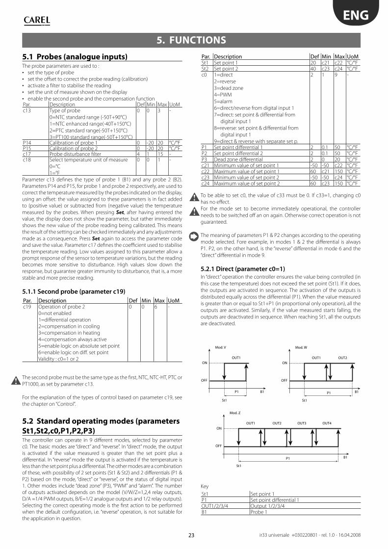
5.2.1 Direct (parameter c0=1)
In “direct” operation the controller ensures the value being controlled (in
this case the temperature) does not exceed the set point (St1). If it does,
the outputs are activated in sequence. The activation of the outputs is
distributed equally across the diff erential (P1). When the value measured
is greater than or equal to St1+P1 (in proportional only operation), all the
outputs are activated. Similarly, if the value measured starts falling, the
outputs are deactivated in sequence. When reaching St1, all the outputs
are deactivated.
Key
St1 Set point 1P1 Set point diff erential 1OUT1/2/3/4 Output 1/2/3/4B1 Probe 1
5. FUNCTIONS

24
ONOUT1
Mod. V
OFF
ON
OFF
St1
B1P1
OUT1OUT2
Mod. W
St1
B1P1
ONOUT1OUT2OUT3OUT4
Mod. Z
OFF
St1
B1P1
ONOUT1
Mod. V
OFF
St1
B1P1 P3
OUT1 OUT2
Mod. W
St1
B1P1 P3 P3 P2
OUT1OUT2 OUT4OUT3
Mod. Z
St1
B1P1 P3 P3 P2
100%OUT1
Mod. V
0%
St1
B1P1 P3
100%
OUT1
Mod. W
0%
St1
B1P1 P3
OUT2
P2P3
100%
OUT1OUT2
Mod. Z
0%
St1
B1P1/2P1/2 P2/2P3
OUT3 OUT4
P2/2P3
ENG
ir33 universale +030220801 - rel. 1.0 - 16.04.2008
5.2.2 Reverse (parameter c0=2)
“Reverse” operation is similar to ”direct” operation, however the outputs
are activated when the value being controlled decreases, starting from
the set point (St1). When the value measured is less than or equal to
St1-P1 (in proportional only operation), all the outputs are activated.
Similarly, if the value measured starts rising, the outputs are deactivated
in sequence. When reaching St1, all the outputs are deactivated.
Key
St1 Set point 1P1 Set point diff erential 1OUT1/2/3/4 Output 1/2/3/4B1 Probe 1
This is the default setting.
5.2.3 Dead zone (parameter c0=3) The aim of this control mode is to bring the measured value within an
interval around the set point (St1), called the dead zone. The extent of the
dead zone depends on the value of parameter P3. Inside the dead zone, the
controller does not activate any outputs, while outside it works in “direct”
mode when the temperature is increasing and in “reverse” mode when it
is decreasing. According to the model used, there may be one or more
outputs in “direct” and “reverse” modes. These are activated or deactivated
one at a time, as already described for modes 1 & 2, according to the value
measured and the settings of St1, P1 and P2.
Key
St1 Set point 1P1/P2 “Reverse”/”direct” diff erentialP3 Dead zone diff erentialOUT1/2/3/4 Output 1/2/3/4B1 Probe 1When the controller only has 1 output, it works in “reverse” mode with
dead zone.
5.2.4 PWM (parameter c0=4) The control logic in PWM mode uses the dead zone, with the outputs
activated based on pulse width modulation (PWM). The output is
activated in a period equal to the value of parameter c12 for a variable
time, calculated as a percentage; the ON time is proportional to the value
measured by B1 inside the diff erential. For small deviations, the output will
be activated for a short time. When exceeding the diff erential, the output
will be always on (100% ON). PWM operation thus allows “proportional”
control of actuators with typically ON/OFF operation (e.g. electric heaters),
so as to improve temperature control. PWM operation can also be used to
gave a modulating 0 to 10 Vdc or 4 to 20 mA control signal on IR33 (DN33)
Universal models A, D with outputs for controlling solid state relays (SSR).
In this case, the accessory code CONV0/10A0 needs to be connected to
convert the signal. In PWM operation, the “direct”/”reverse” icon fl ashes.
Key
St1 Set point 1P1/P2 “Reverse”/”direct” diff erentialP3 Dead zone diff erentialOUT1/2/3/4 Output 1/2/3/4B1 Probe 1
When the controller only has 1 output, it works in “reverse” mode with
dead zone.
PWM mode should not be used with compressors or other actuators
whose reliability may be aff ected by starting/stopping too frequently.
For relay outputs, parameter c12 should not be set too low, so as to not
compromise the life of the component..
5.2.5 Alarm (parameter c0=5)
In mode 5, one or more outputs are activated to signal a probe
disconnected or short-circuited alarm or a high or low temperature alarm.
Models V and W only have one alarm relay, while model Z has two: relay
3 is activated for general alarms and for the low temperature alarm, relays
4 is activated for general alarms and for the high temperature alarm. The
activation of the alarm relay is cumulative to the other signals in the other
operating modes, that is, alarm code on the display and audible signal.
For models W & Z, the relays not used to signal the alarms are used for
control, as for mode 3 and shown the following diagrams. This operation
mode is not suitable for the models B and E.
Par. Description Def Min Max UoMP25 Low temperature alarm threshold
P29=0, P25=0: threshold disabled;
P29=1, P25= -50: thresh. disabled
-50 -50 P26 °C/°F
P26 High temperature alarm threshold
P29=0, P26=0: threshold disabled;
P29=1, P26= 150: thresh. disabled
150 P25 150 °C/°F
P27 Alarm diff erential 2 0 50 °C/°FP28 Alarm delay time 120 0 250 minP29 Type of alarm threshold
0=relative;
1=absolute.
1 0 1 -
25
ONOUT1 (LOW ALARM)
Mod. V
Mod. Z
OFF
B1P27
P25
ON
OFF
B1P27
P26
P27
P25
St1
St1P26
ONOUT1
Mod. W
OUT2 (HIGH ALARM)
OUT3 (LOW ALARM) OUT4 (HIGH ALARM)
OFF
B1P1 P3
OUT1
B1P1 P3 P3 P27
OUT2
P2
ONOUT1
Mod. V
OFF
St1
B1P1
ONOUT1
Mod. V
OFF
St2
B1P2
ONOUT1
Mod. V
OFF
St1
B1P1
ONOUT1
Mod. V
OFF
St2
B1P2
ONOUT1
Mod. V
OFF
St1
B1P1
ONOUT1
Mod. V
OFF
St2
B1P2
ENG
ir33 universale +030220801 - rel. 1.0 - 16.04.2008
Key
St1 Set point 1P1 “Reverse” diff erentialP2 “Direct” diff erentialP3 Dead zone diff erentialP27 Alarm diff erentialOUT1/2/3/4 Output 1/2/3/4B1 Probe 1
Parameter P28 represents the “alarm activation delay” in minutes; the
low temperature alarm (E05) is activated only if the temperature remains
below the value of P25 for a time greater than P28. The alarm may relative
or absolute, depending on the value of parameter P29. In the former case
(P29=0), the value of P25 indicates the deviation from the set point and
thus the activation point for the low temperature alarm is: set point - P25.
If the set point changes, the activation point also changes automatically.
In the latter case (P29=1), the value of P25 indicates the low temperature
alarm threshold. The low temperature alarm active is signalled by
the buzzer and code E05 on the display. The same applies to the high
temperature alarm (E04), with P26 instead of P25.
Alarm set point relative to working set point P29=0Low temperature alarm High temperature alarmEnable Disable Enable DisableSetpoint-P25 Setpoint-P25+P27 Setpoint+P26 Setpoint +P26-P27
Absolute alarm set point P29=1Low temperature alarm High temperature alarmEnable Disable Enable DisableP25 P25+P27 P26 P26-P27
The low and high temperature alarms are automatically reset; if there is
an alarm active on the control probe, these alarms are deactivated and
monitoring is reinitialised.
When alarms E04 and E05 are active, the buzzer can be muted by pressing
Prg/mute. The display remains active.
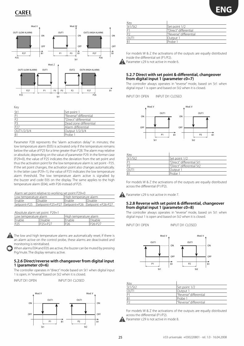
5.2.6 Direct/reverse with changeover from digital input 1 (parameter c0=6)
The controller operates in “direct” mode based on St1 when digital input
1 is open, in “reverse” based on St2 when it is closed.
INPUT DI1 OPEN INPUT DI1 CLOSED
KeySt1/St2 Set point 1/2P1 “Direct” diff erentialP2 “Reverse” diff erentialOUT1 Output 1B1 Probe 1
For models W & Z the activations of the outputs are equally distributed
inside the diff erential set (P1/P2).
Parameter c29 is not active in mode 6.
5.2.7 Direct with set point & diff erential, changeover from digital input 1 (parameter c0=7)
The controller always operates in “reverse” mode, based on St1 when
digital input 1 is open and based on St2 when it is closed.
INPUT DI1 OPEN INPUT DI1 CLOSED
KeySt1/St2 Set point 1/2P1 “Direct” diff erential St1P2 “Direct” diff erential St2OUT1 Output 1B1 Probe 1
For models W & Z the activations of the outputs are equally distributed
across the diff erential (P1/P2).
Parameter c29 is not active in mode 7.
5.2.8 Reverse with set point & diff erential, changeover from digital input 1 (parameter c0=8)
The controller always operates in “reverse” mode, based on St1 when
digital input 1 is open and based on St2 when it is closed.
INPUT DI1 OPEN INPUT DI1 CLOSED
KeySt1/St2 Set point 1/2OUT1 Output 1P1 “Reverse” diff erentialB1 Probe 1P2 “Reverse” diff erential
For models W & Z the activations of the outputs are equally distributed
across the diff erential (P1/P2).
Parameter c29 is not active in mode 8.
26
St1 St2
St1 St2
OUT1 OUT2
Mod. W
B1P1 P2
OUT1OUT2 OUT4OUT3
ON
OFF
ON
OFF
Mod. Z
B1P1 P2
ENG
ir33 universale +030220801 - rel. 1.0 - 16.04.2008
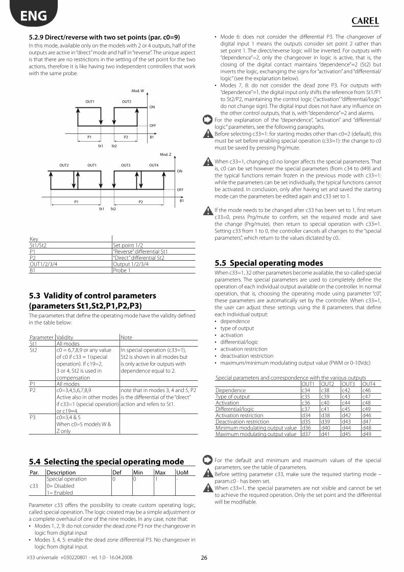
5.2.9 Direct/reverse with two set points (par. c0=9)
In this mode, available only on the models with 2 or 4 outputs, half of the
outputs are active in “direct” mode and half in “reverse”. The unique aspect
is that there are no restrictions in the setting of the set point for the two
actions, therefore it is like having two independent controllers that work
with the same probe.
KeySt1/St2 Set point 1/2P1 “Reverse” diff erential St1P2 “Direct” diff erential St2OUT1/2/3/4 Output 1/2/3/4B1 Probe 1
5.3 Validity of control parameters
(parameters St1,St2,P1,P2,P3)The parameters that defi ne the operating mode have the validity defi ned
in the table below:
Parameter Validity NoteSt1 All modesSt2 c0 = 6,7,8,9 or any value
of c0 if c33 = 1(special
operation). If c19=2,
3 or 4, St2 is used in
compensation
In special operation (c33=1),
St2 is shown in all modes but
is only active for outputs with
dependence equal to 2.
P1 All modesP2 c0=3,4,5,6,7,8,9
Active also in other modes
if c33=1 (special operation)
or c19=4.
note that in modes 3, 4 and 5, P2
is the diff erential of the “direct”
action and refers to St1.
P3 c0=3,4 & 5
When c0=5 models W &
Z only
5.4 Selecting the special operating mode
Par. Description Def Min Max UoM
c33
Special operation
0= Disabled
1= Enabled
0 0 1 -
Parameter c33 off ers the possibility to create custom operating logic,
called special operation. The logic created may be a simple adjustment or
a complete overhaul of one of the nine modes. In any case, note that:
Modes 1, 2, 9: do not consider the dead zone P3 nor the changeover in • logic from digital input
Modes 3, 4, 5: enable the dead zone diff erential P3. No changeover in • logic from digital input.
Mode 6: does not consider the diff erential P3. The changeover of • digital input 1 means the outputs consider set point 2 rather than
set point 1. The direct/reverse logic will be inverted. For outputs with
“dependence”=2, only the changeover in logic is active, that is, the
closing of the digital contact maintains “dependence”=2 (St2) but
inverts the logic, exchanging the signs for “activation” and “diff erential/
logic” (see the explanation below).
Modes 7, 8: do not consider the dead zone P3. For outputs with • “dependence”=1, the digital input only shifts the reference from St1/P1
to St2/P2, maintaining the control logic (“activation” “diff erential/logic”
do not change sign). The digital input does not have any infl uence on
the other control outputs, that is, with “dependence”=2 and alarms.
For the explanation of the “dependence”, “activation” and “diff erential/
logic” parameters, see the following paragraphs.
Before selecting c33=1: for starting modes other than c0=2 (default), this
must be set before enabling special operation (c33=1): the change to c0
must be saved by pressing Prg/mute.
When c33=1, changing c0 no longer aff ects the special parameters. That
is, c0 can be set however the special parameters (from c34 to d49) and
the typical functions remain frozen in the previous mode with c33=1:
while the parameters can be set individually, the typical functions cannot
be activated. In conclusion, only after having set and saved the starting
mode can the parameters be edited again and c33 set to 1.
If the mode needs to be changed after c33 has been set to 1, fi rst return
c33=0, press Prg/mute to confi rm, set the required mode and save
the change (Prg/mute), then return to special operation with c33=1.
Setting c33 from 1 to 0, the controller cancels all changes to the “special
parameters”, which return to the values dictated by c0..
5.5 Special operating modesWhen c33=1, 32 other parameters become available, the so-called special
parameters. The special parameters are used to completely defi ne the
operation of each individual output available on the controller. In normal
operation, that is, choosing the operating mode using parameter “c0”,
these parameters are automatically set by the controller. When c33=1,
the user can adjust these settings using the 8 parameters that defi ne
each individual output:
dependence• type of output• activation• diff erential/logic• activation restriction• deactivation restriction• maximum/minimum modulating output value (PWM or 0-10Vdc)•
Special parameters and correspondence with the various outputsOUT1 OUT2 OUT3 OUT4
Dependence c34 c38 c42 c46Type of output c35 c39 c43 c47Activation c36 c40 c44 c48Diff erential/logic c37 c41 c45 c49Activation restriction d34 d38 d42 d46Deactivation restriction d35 d39 d43 d47Minimum modulating output value d36 d40 d44 d48Maximum modulating output value d37 d41 d45 d49
For the default and minimum and maximum values of the special
parameters, see the table of parameters.
Before setting parameter c33, make sure the required starting mode –
param.c0 - has been set.
When c33=1, the special parameters are not visible and cannot be set
to achieve the required operation. Only the set point and the diff erential
will be modifi able.
27
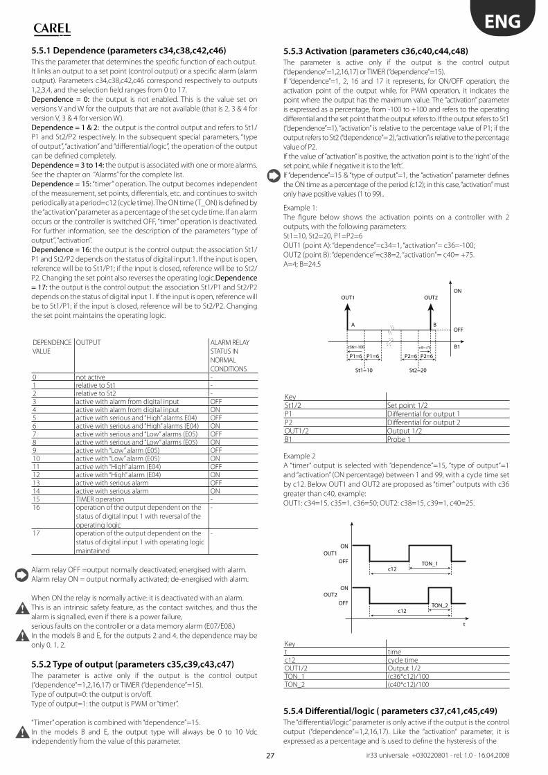
St1=10
c36=-100
St2=20
c40=+75
OUT1
A B
OUT2
B1
P1=6 P1=6 P2=6 P2=6
ON
OFF
ON
OUT1
OUT2OFF
t
c12TON_2
ON
OFFc12
TON_1
ENG
ir33 universale +030220801 - rel. 1.0 - 16.04.2008
5.5.1 Dependence (parameters c34,c38,c42,c46)
This the parameter that determines the specifi c function of each output.
It links an output to a set point (control output) or a specifi c alarm (alarm
output). Parameters c34,c38,c42,c46 correspond respectively to outputs
1,2,3,4, and the selection fi eld ranges from 0 to 17.
Dependence = 0: the output is not enabled. This is the value set on
versions V and W for the outputs that are not available (that is 2, 3 & 4 for
version V, 3 & 4 for version W).
Dependence = 1 & 2: the output is the control output and refers to St1/
P1 and St2/P2 respectively. In the subsequent special parameters, “type
of output”, “activation” and “diff erential/logic”, the operation of the output
can be defi ned completely.
Dependence = 3 to 14: the output is associated with one or more alarms.
See the chapter on “Alarms” for the complete list.
Dependence = 15: “timer” operation. The output becomes independent
of the measurement, set points, diff erentials, etc. and continues to switch
periodically at a period=c12 (cycle time). The ON time (T_ON) is defi ned by
the “activation” parameter as a percentage of the set cycle time. If an alarm
occurs or the controller is switched OFF, “timer” operation is deactivated.
For further information, see the description of the parameters “type of
output”, “activation”.
Dependence = 16: the output is the control output: the association St1/
P1 and St2/P2 depends on the status of digital input 1. If the input is open,
reference will be to St1/P1; if the input is closed, reference will be to St2/
P2. Changing the set point also reverses the operating logic.Dependence = 17: the output is the control output: the association St1/P1 and St2/P2
depends on the status of digital input 1. If the input is open, reference will
be to St1/P1; if the input is closed, reference will be to St2/P2. Changing
the set point maintains the operating logic.
DEPENDENCE
VALUE
OUTPUT ALARM RELAY
STATUS IN
NORMAL
CONDITIONS0 not active -1 relative to St1 -2 relative to St2 -3 active with alarm from digital input OFF4 active with alarm from digital input ON5 active with serious and “High” alarms E04) OFF6 active with serious and “High” alarms (E04) ON7 active with serious and “Low” alarms (E05) OFF8 active with serious and “Low” alarms (E05) ON9 active with “Low” alarm (E05) OFF10 active with “Low” alarm (E05) ON11 active with “High” alarm (E04) OFF12 active with “High” alarm (E04) ON13 active with serious alarm OFF14 active with serious alarm ON15 TIMER operation -16 operation of the output dependent on the
status of digital input 1 with reversal of the
operating logic
-
17 operation of the output dependent on the
status of digital input 1 with operating logic
maintained
-
Alarm relay OFF =output normally deactivated; energised with alarm.
Alarm relay ON = output normally activated; de-energised with alarm.
When ON the relay is normally active: it is deactivated with an alarm.
This is an intrinsic safety feature, as the contact switches, and thus the
alarm is signalled, even if there is a power failure,
serious faults on the controller or a data memory alarm (E07/E08.)
In the models B and E, for the outputs 2 and 4, the dependence may be
only 0, 1, 2.
5.5.2 Type of output (parameters c35,c39,c43,c47)
The parameter is active only if the output is the control output
(“dependence”=1,2,16,17) or TIMER (“dependence”=15).
Type of output=0: the output is on/off .
Type of output=1: the output is PWM or “timer”.
“Timer” operation is combined with “dependence”=15.
In the models B and E, the output type will always be 0 to 10 Vdc
independently from the value of this parameter.
5.5.3 Activation (parameters c36,c40,c44,c48)
The parameter is active only if the output is the control output
(“dependence”=1,2,16,17) or TIMER (“dependence”=15).
If “dependence”=1, 2, 16 and 17 it represents, for ON/OFF operation, the
activation point of the output while, for PWM operation, it indicates the
point where the output has the maximum value. The “activation” parameter
is expressed as a percentage, from -100 to +100 and refers to the operating
diff erential and the set point that the output refers to. If the output refers to St1
(“dependence”=1), “activation” is relative to the percentage value of P1; if the
output refers to St2 (“dependence”= 2), “activation” is relative to the percentage
value of P2.
If the value of “activation” is positive, the activation point is to the ‘right’ of the
set point, while if negative it is to the ‘left’.
If “dependence”=15 & “type of output”=1, the “activation” parameter defi nes
the ON time as a percentage of the period (c12); in this case, “activation” must
only have positive values (1 to 99)..
Example 1:
The fi gure below shows the activation points on a controller with 2
outputs, with the following parameters:
St1=10, St2=20, P1=P2=6
OUT1 (point A): “dependence”=c34=1, “activation”= c36=-100;
OUT2 (point B): “dependence”=c38=2, “activation”= c40= +75.
A=4; B=24.5
KeySt1/2 Set point 1/2P1 Diff erential for output 1P2 Diff erential for output 2OUT1/2 Output 1/2B1 Probe 1
Example 2
A “timer” output is selected with “dependence”=15, “type of output”=1
and “activation” (ON percentage) between 1 and 99, with a cycle time set
by c12. Below OUT1 and OUT2 are proposed as “timer” outputs with c36
greater than c40, example:
OUT1: c34=15, c35=1, c36=50; OUT2: c38=15, c39=1, c40=25.
Keyt timec12 cycle timeOUT1/2 Output 1/2TON_1 (c36*c12)/100TON_2 (c40*c12)/100
5.5.4 Diff erential/logic ( parameters c37,c41,c45,c49)
The “diff erential/logic” parameter is only active if the output is the control
output (“dependence”=1,2,16,17). Like the “activation” parameter, it is
expressed as a percentage and is used to defi ne the hysteresis of the
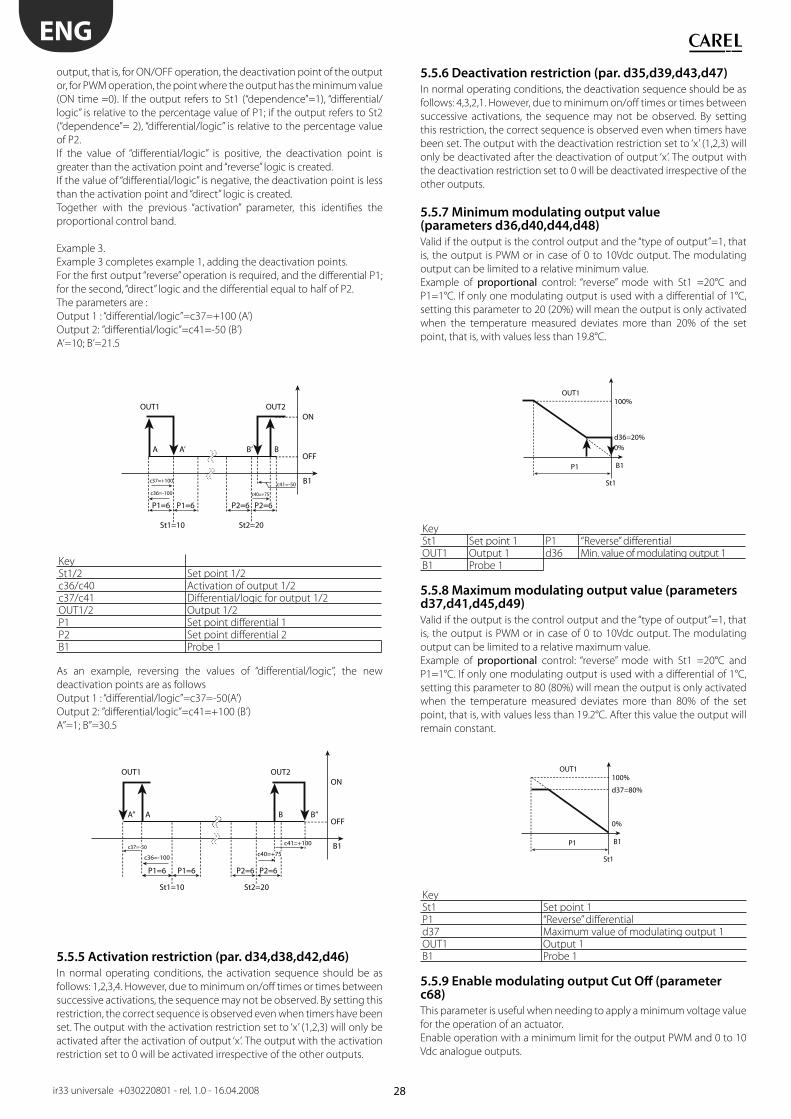
28
c36=-100
c37=+100c41=-50
c40=+75
OUT1
A A’ B’ B
OUT2
B1
P1=6 P1=6 P2=6 P2=6
St1=10 St2=20
ON
OFF
100%OUT1
0%d36=20%
St1
B1P1
100%OUT1
0%
d37=80%
St1
B1P1
c36=-100
OUT1
A’’ A B B’’
OUT2
B1
P1=6 P1=6 P2=6 P2=6
St1=10 St2=20
ON
OFF
c40=+75
c41=+100c37=-50
ENG
ir33 universale +030220801 - rel. 1.0 - 16.04.2008
output, that is, for ON/OFF operation, the deactivation point of the output
or, for PWM operation, the point where the output has the minimum value
(ON time =0). If the output refers to St1 (“dependence”=1), “diff erential/
logic” is relative to the percentage value of P1; if the output refers to St2
(“dependence”= 2), “diff erential/logic” is relative to the percentage value
of P2.
If the value of “diff erential/logic” is positive, the deactivation point is
greater than the activation point and “reverse” logic is created.
If the value of “diff erential/logic” is negative, the deactivation point is less
than the activation point and “direct” logic is created.
Together with the previous “activation” parameter, this identifi es the
proportional control band.
Example 3.
Example 3 completes example 1, adding the deactivation points.
For the fi rst output “reverse” operation is required, and the diff erential P1;
for the second, “direct” logic and the diff erential equal to half of P2.
The parameters are :
Output 1 : “diff erential/logic”=c37=+100 (A’)
Output 2: ”diff erential/logic”=c41=-50 (B’)
A’=10; B’=21.5
KeySt1/2 Set point 1/2c36/c40 Activation of output 1/2c37/c41 Diff erential/logic for output 1/2OUT1/2 Output 1/2P1 Set point diff erential 1P2 Set point diff erential 2B1 Probe 1
As an example, reversing the values of “diff erential/logic”, the new
deactivation points are as follows
Output 1 : “diff erential/logic”=c37=-50(A’)
Output 2: ”diff erential/logic”=c41=+100 (B’)
A’’=1; B’’=30.5
5.5.5 Activation restriction (par. d34,d38,d42,d46)
In normal operating conditions, the activation sequence should be as
follows: 1,2,3,4. However, due to minimum on/off times or times between
successive activations, the sequence may not be observed. By setting this
restriction, the correct sequence is observed even when timers have been
set. The output with the activation restriction set to ‘x’ (1,2,3) will only be
activated after the activation of output ‘x’. The output with the activation
restriction set to 0 will be activated irrespective of the other outputs.
5.5.6 Deactivation restriction (par. d35,d39,d43,d47)
In normal operating conditions, the deactivation sequence should be as
follows: 4,3,2,1. However, due to minimum on/off times or times between
successive activations, the sequence may not be observed. By setting
this restriction, the correct sequence is observed even when timers have
been set. The output with the deactivation restriction set to ‘x’ (1,2,3) will
only be deactivated after the deactivation of output ‘x’. The output with
the deactivation restriction set to 0 will be deactivated irrespective of the
other outputs.
5.5.7 Minimum modulating output value (parameters d36,d40,d44,d48)
Valid if the output is the control output and the “type of output”=1, that
is, the output is PWM or in case of 0 to 10Vdc output. The modulating
output can be limited to a relative minimum value.
Example of proportional control: “reverse” mode with St1 =20°C and
P1=1°C. If only one modulating output is used with a diff erential of 1°C,
setting this parameter to 20 (20%) will mean the output is only activated
when the temperature measured deviates more than 20% of the set
point, that is, with values less than 19.8°C.
KeySt1 Set point 1 P1 “Reverse” diff erentialOUT1 Output 1 d36 Min. value of modulating output 1B1 Probe 1
5.5.8 Maximum modulating output value (parameters d37,d41,d45,d49)
Valid if the output is the control output and the “type of output”=1, that
is, the output is PWM or in case of 0 to 10Vdc output. The modulating
output can be limited to a relative maximum value.
Example of proportional control: “reverse” mode with St1 =20°C and
P1=1°C. If only one modulating output is used with a diff erential of 1°C,
setting this parameter to 80 (80%) will mean the output is only activated
when the temperature measured deviates more than 80% of the set
point, that is, with values less than 19.2°C. After this value the output will
remain constant.
KeySt1 Set point 1P1 “Reverse” diff erentiald37 Maximum value of modulating output 1OUT1 Output 1B1 Probe 1
5.5.9 Enable modulating output Cut Off (parameter c68)
This parameter is useful when needing to apply a minimum voltage value
for the operation of an actuator.
Enable operation with a minimum limit for the output PWM and 0 to 10
Vdc analogue outputs.
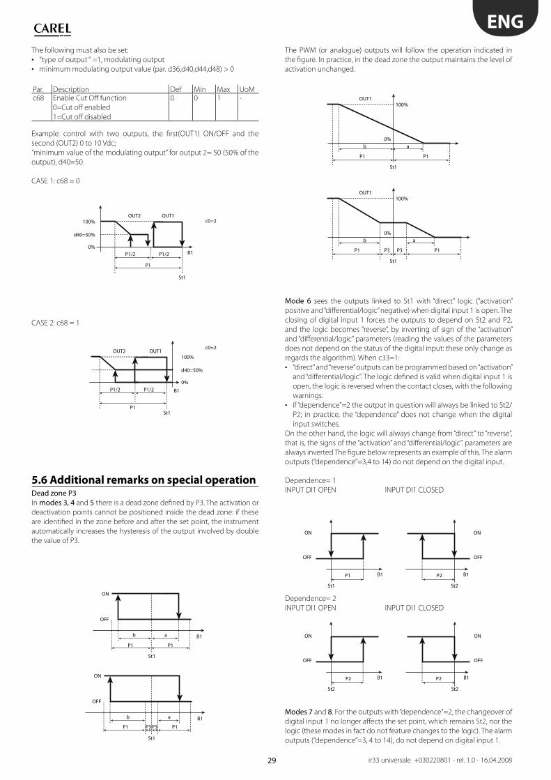
29
100%
0%
d40=50%
St1
B1
P1
P1/2 P1/2
100%OUT2 OUT1
OUT2 OUT1
c0=2
c0=2
0%
d40=50%
St1
B1
P1
P1/2 P1/2
ON
OFF
St1
B1
P1 P1
b a
ON
OFF
St1
B1
P1 P3 P3 P1
b a
100%OUT1
0%
St1
P1 P1
b a
100%OUT1
0%
St1
P1 P3 P3 P1
b a
ON
OFF
St1
B1P1
ON
OFF
St2
B1P2
ON
OFF
St2
B1P2
ON
OFF
St2
B1P2
ENG
ir33 universale +030220801 - rel. 1.0 - 16.04.2008
The following must also be set:
“type of output “ =1, modulating output• minimum modulating output value (par. d36,d40,d44,d48) > 0•
Par. Description Def Min Max UoMc68 Enable Cut Off function
0=Cut off enabled
1=Cut off disabled
0 0 1 -
Example: control with two outputs, the fi rst(OUT1) ON/OFF and the
second (OUT2) 0 to 10 Vdc;
“minimum value of the modulating output” for output 2= 50 (50% of the
output), d40=50.
CASE 1: c68 = 0
CASE 2: c68 = 1
5.6 Additional remarks on special operationDead zone P3In modes 3, 4 and 5 there is a dead zone defi ned by P3. The activation or
deactivation points cannot be positioned inside the dead zone: if these
are identifi ed in the zone before and after the set point, the instrument
automatically increases the hysteresis of the output involved by double
the value of P3.
The PWM (or analogue) outputs will follow the operation indicated in
the fi gure. In practice, in the dead zone the output maintains the level of
activation unchanged.
Mode 6 sees the outputs linked to St1 with “direct” logic (“activation”
positive and “diff erential/logic” negative) when digital input 1 is open. The
closing of digital input 1 forces the outputs to depend on St2 and P2,
and the logic becomes “reverse”, by inverting of sign of the “activation”
and “diff erential/logic” parameters (reading the values of the parameters
does not depend on the status of the digital input: these only change as
regards the algorithm). When c33=1:
“direct” and “reverse” outputs can be programmed based on “activation” • and “diff erential/logic”. The logic defi ned is valid when digital input 1 is
open, the logic is reversed when the contact closes, with the following
warnings:
if “dependence”=2 the output in question will always be linked to St2/• P2; in practice, the “dependence” does not change when the digital
input switches.
On the other hand, the logic will always change from “direct” to “reverse”,
that is, the signs of the “activation” and “diff erential/logic”. parameters are
always inverted The fi gure below represents an example of this. The alarm
outputs (“dependence”=3,4 to 14) do not depend on the digital input.
Dependence= 1
INPUT DI1 OPEN INPUT DI1 CLOSED
Dependence= 2
INPUT DI1 OPEN INPUT DI1 CLOSED
Modes 7 and 8. For the outputs with “dependence”=2, the changeover of
digital input 1 no longer aff ects the set point, which remains St2, nor the
logic (these modes in fact do not feature changes to the logic). The alarm
outputs (“dependence”=3, 4 to 14), do not depend on digital input 1.
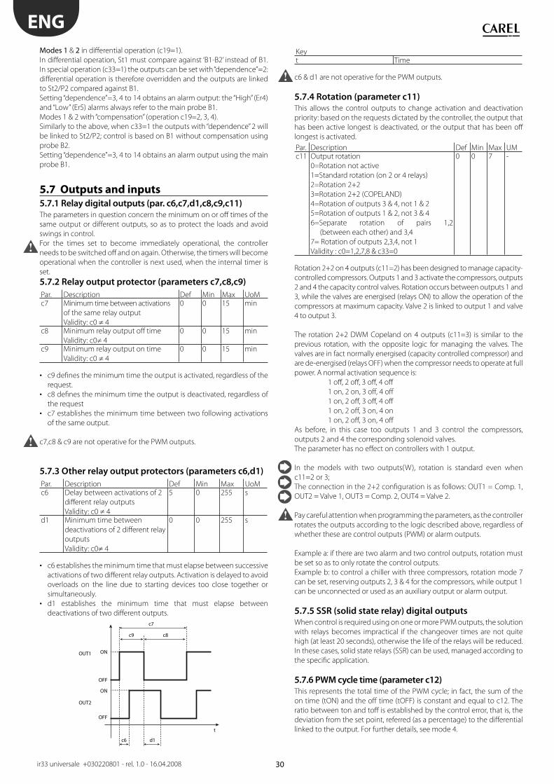
30
ON
OUT1
OUT2
OFF
t
c6 d1
c9
c7
c8
ON
OFF
ENG
ir33 universale +030220801 - rel. 1.0 - 16.04.2008
Modes 1 & 2 in diff erential operation (c19=1).
In diff erential operation, St1 must compare against ‘B1-B2’ instead of B1.
In special operation (c33=1) the outputs can be set with “dependence”=2:
diff erential operation is therefore overridden and the outputs are linked
to St2/P2 compared against B1.
Setting “dependence”=3, 4 to 14 obtains an alarm output: the “High” (Er4)
and “Low” (Er5) alarms always refer to the main probe B1.
Modes 1 & 2 with “compensation” (operation c19=2, 3, 4).
Similarly to the above, when c33=1 the outputs with “dependence” 2 will
be linked to St2/P2; control is based on B1 without compensation using
probe B2.
Setting “dependence”=3, 4 to 14 obtains an alarm output using the main
probe B1.
5.7 Outputs and inputs
5.7.1 Relay digital outputs (par. c6,c7,d1,c8,c9,c11)
The parameters in question concern the minimum on or off times of the
same output or diff erent outputs, so as to protect the loads and avoid
swings in control.
For the times set to become immediately operational, the controller
needs to be switched off and on again. Otherwise, the timers will become
operational when the controller is next used, when the internal timer is
set.
5.7.2 Relay output protector (parameters c7,c8,c9)
Par. Description Def Min Max UoMc7 Minimum time between activations
of the same relay output
Validity: c0 ≠ 4
0 0 15 min
c8 Minimum relay output off time
Validity: c0≠ 4
0 0 15 min
c9 Minimum relay output on time
Validity: c0 ≠ 4
0 0 15 min
c9 defi nes the minimum time the output is activated, regardless of the • request.
c8 defi nes the minimum time the output is deactivated, regardless of • the request
c7 establishes the minimum time between two following activations • of the same output.
c7,c8 & c9 are not operative for the PWM outputs.
5.7.3 Other relay output protectors (parameters c6,d1)
Par. Description Def Min Max UoMc6 Delay between activations of 2
diff erent relay outputs
Validity: c0 ≠ 4
5 0 255 s
d1 Minimum time between
deactivations of 2 diff erent relay
outputs
Validity: c0≠ 4
0 0 255 s
c6 establishes the minimum time that must elapse between successive • activations of two diff erent relay outputs. Activation is delayed to avoid
overloads on the line due to starting devices too close together or
simultaneously.
d1 establishes the minimum time that must elapse between • deactivations of two diff erent outputs.
Keyt Time
c6 & d1 are not operative for the PWM outputs.
5.7.4 Rotation (parameter c11)
This allows the control outputs to change activation and deactivation
priority: based on the requests dictated by the controller, the output that
has been active longest is deactivated, or the output that has been off
longest is activated.
Par. Description Def Min Max UMc11 Output rotation
0=Rotation not active
1=Standard rotation (on 2 or 4 relays)
2=Rotation 2+2
3=Rotation 2+2 (COPELAND)
4=Rotation of outputs 3 & 4, not 1 & 2
5=Rotation of outputs 1 & 2, not 3 & 4
6=Separate rotation of pairs 1,2
(between each other) and 3,4
7= Rotation of outputs 2,3,4, not 1
Validity : c0=1,2,7,8 & c33=0
0 0 7 -
Rotation 2+2 on 4 outputs (c11=2) has been designed to manage capacity-
controlled compressors. Outputs 1 and 3 activate the compressors, outputs
2 and 4 the capacity control valves. Rotation occurs between outputs 1 and
3, while the valves are energised (relays ON) to allow the operation of the
compressors at maximum capacity. Valve 2 is linked to output 1 and valve
4 to output 3.
The rotation 2+2 DWM Copeland on 4 outputs (c11=3) is similar to the
previous rotation, with the opposite logic for managing the valves. The
valves are in fact normally energised (capacity controlled compressor) and
are de-energised (relays OFF) when the compressor needs to operate at full
power. A normal activation sequence is:
1 off , 2 off , 3 off , 4 off
1 on, 2 on, 3 off , 4 off
1 on, 2 off , 3 off , 4 off
1 on, 2 off , 3 on, 4 on
1 on, 2 off , 3 on, 4 off
As before, in this case too outputs 1 and 3 control the compressors,
outputs 2 and 4 the corresponding solenoid valves.
The parameter has no eff ect on controllers with 1 output.
In the models with two outputs(W), rotation is standard even when
c11=2 or 3;
The connection in the 2+2 confi guration is as follows: OUT1 = Comp. 1,
OUT2 = Valve 1, OUT3 = Comp. 2, OUT4 = Valve 2.
Pay careful attention when programming the parameters, as the controller
rotates the outputs according to the logic described above, regardless of
whether these are control outputs (PWM) or alarm outputs.
Example a: if there are two alarm and two control outputs, rotation must
be set so as to only rotate the control outputs.
Example b: to control a chiller with three compressors, rotation mode 7
can be set, reserving outputs 2, 3 & 4 for the compressors, while output 1
can be unconnected or used as an auxiliary output or alarm output.
5.7.5 SSR (solid state relay) digital outputs
When control is required using on one or more PWM outputs, the solution
with relays becomes impractical if the changeover times are not quite
high (at least 20 seconds), otherwise the life of the relays will be reduced.
In these cases, solid state relays (SSR) can be used, managed according to
the specifi c application.
5.7.6 PWM cycle time (parameter c12)
This represents the total time of the PWM cycle; in fact, the sum of the
on time (tON) and the off time (tOFF) is constant and equal to c12. The
ratio between ton and toff is established by the control error, that is, the
deviation from the set point, referred (as a percentage) to the diff erential
linked to the output. For further details, see mode 4.
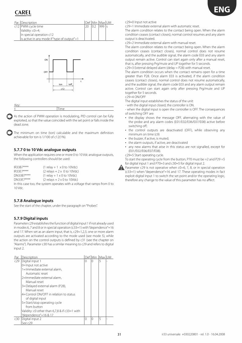
31
t
c12
ton toff
ON
OFF
ENG
ir33 universale +030220801 - rel. 1.0 - 16.04.2008
Par. Description Def Min Max UMc12 PWM cycle time
Validity: c0=4;
In special operation c12
is active in any mode if “type of output”=1
20 0.2 999 s
Key:t Time
As the action of PWM operation is modulating, PID control can be fully
exploited, so that the value coincided with the set point or falls inside the
dead zone.
The minimum on time (ton) calculable and the maximum defi nition
achievable for ton is 1/100 of c12(1%).
5.7.7 0 to 10 Vdc analogue outputs
When the application requires one or more 0 to 10 Vdc analogue outputs,
the following controllers should be used:
IR33B7**** (1 relay + 1 x 0 to 10Vdc)
IR33E7**** (2 relays + 2 x 0 to 10Vdc)
DN33B7**** (1 relay + 1 x 0 to 10Vdc)
DN33E7**** (2 relays + 2 x 0 to 10Vdc)
In this case too, the system operates with a voltage that ramps from 0 to
10 Vdc.
5.7.8 Analogue inputs
See the start of the chapter, under the paragraph on “Probes”.
5.7.9 Digital inputs
Parameter c29 establishes the function of digital input 1 if not already used
in modes 6, 7 and 8 or in special operation (c33=1) with “dependence”=16
and 17. When set as an alarm input, that is, c29=1,2,3, one or more alarm
outputs are activated according to the mode used (see mode 5), while
the action on the control outputs is defi ned by c31 (see the chapter on
“Alarms”). Parameter c30 has a similar meaning to c29 and refers to digital
input 2.
Par. Description Def Min Max UMc29 Digital input 1
0= Input not active
1= Immediate external alarm,
Automatic reset
2=Immediate external alarm,
Manual reset
3= Delayed external alarm (P28),
Manual reset
4= Control ON/OFF in relation to status
of digital input
5= Start/stop operating cycle
from button
Validity: c0 other than 6,7,8 & if c33=1 with
“dependence”=16 & 17
0 0 5 -
c30 Digital input 2
See c29
0 0 5 -
c29=0 Input not active
c29=1 Immediate external alarm with automatic reset.
The alarm condition relates to the contact being open. When the alarm
condition ceases (contact closes), normal control resumes and any alarm
output is deactivated.
c29=2 Immediate external alarm with manual reset.
The alarm condition relates to the contact being open. When the alarm
condition ceases (contact closes), normal control does not resume
automatically, and the audible signal, the alarm code E03 and any alarm
output remain active. Control can start again only after a manual reset,
that is, after pressing Prg/mute and UP together for 5 seconds.
c29=3 External delayed alarm (delay = P28) with manual reset.
The alarm condition occurs when the contact remains open for a time
greater than P28. Once alarm E03 is activated, if the alarm condition
ceases (contact closes), normal control does not resume automatically,
and the audible signal, the alarm code E03 and any alarm output remain
active. Control can start again only after pressing Prg/mute and UP
together for 5 seconds.
c29=4 ON/OFF
The digital input establishes the status of the unit:
- with the digital input closed, the controller is ON.
- when the digital input is open the controller is OFF. The consequences
of switching OFF are:
the display shows the message OFF, alternating with the value of • the probe and any alarm codes (E01/E02/E06/E07/E08) active before
switching off ;
the control outputs are deactivated (OFF), while observing any • minimum on time (c9)
the buzzer, if active, is muted;• the alarm outputs, if active, are deactivated• any new alarms that arise in this status are not signalled, except for • (E01/E02/E06/E07/E08).
c29=5 Start operating cycle.
To start the operating cycle from the button, P70 must be =2 and P29 =5
for digital input 1 and P70=3 and c30=5 for digital input 2.
Parameter c29 is not operative when c0=6, 7, 8, or in special operation
(c33=1) when “dependence”=16 and 17. These operating modes in fact
exploit digital input 1 to switch the set point and/or the operating logic,
therefore any change to the value of this parameter has no aff ect.
32
ENG
ir33 universale +030220801 - rel. 1.0 - 16.04.2008
6. CONTROL
ON/OFF and PID control
The controller can operate with two types of control:
ON/OFF (proportional), in which the actuator either operates at full • power or is off . This is a simple control mode that in certain cases can
achieve satisfying results;
PID, useful for systems in which the response of the controlled value • compared to the changeable value does allow to eliminate the error
in steady operation and improve the regulation. The changeable value
becomes an analogue value that continuously varies between 0 and 100%.
In PID control, the proportional band coincides with the diff erential
(parameters P1/P2).
6.1 Type of control (parameter c32)
Par. Description Def Min Max UMc5 Type control
0=ON/OFF(proportional)
1=Proportional+Integral+Derivative (PID)
0 0 1 -
This parameter is used to set the most suitable type of control for the
process in question.
With PID, eff ective control means the controlled value coincides with
the set point or falls within the dead zone; in these conditions, a series
of outputs may be active even if not envisaged in the original control
diagram. This is the most evident eff ect of the integral factor.
PID control, before being applied, requires proportional control only
without swings and with good stability in the diff erentials: only when
there is stable P control can PID guarantee maximum eff ectiveness;
6.2 ti_PID, td_PID (parameters c62,c63)These are the PID parameters to be set for the application
Par. Description Def Min Max UoMc62 td_PID 600 0 999 sc63 ti_PID 0 0 999 s
To eliminate the eff ect of the integral and derivative factors, set the
respective parameters ti and td=0
Setting td=0 and ti ≠ 0 achieves P+I operation, widely used for controlling
environments in which the temperature does not have considerable
variations.
To eliminate the error in steady operation, PI control can be implemented,
as the integral factor reduces the average value of the error. Nonetheless,
a high impact of this factor (remember that it contributes in an inversely
proportional way to the time ‘ti’) may increase temperature swings,
overshoots and the time taken for the controlled variable to increase and
decrease, bringing instability
To resolve such overshoots due to the use of the integral time, the
derivative factor can be introduced, which acts as a damper to the swings.
Nonetheless, needlessly increasing the derivative factor (increasing the
time ‘td’) increases the time taken for the controlled variable to increase
and decrease and can also cause system instability. The derivative factor
however has no aff ect whatsoever on the error in steady operation.
6.3 Auto-Tuning (parameter c64)The controller leaves the factory with default settings of the PID
parameters; these allow standard PID control, but are not optimised for
the system that IR33 controls. Consequently, the Auto-Tuning procedure
can be used to fi ne-tune the 3 parameters involved, so as to ensure control
that is optimised for the system where it is installed: diff erent systems,
with diff erent dynamics, will generate parameters that diff er greatly.
Auto-Tuning includes two operating procedures:
• Tuning the controller when commissioning the system.• Fine-tuning the controller with parameters that have already been tuned, during normal operation.
In both modes, the control fi rst needs to be programmed setting the
following parameters:
c0 =1 or 2, that is, “direct” or “reverse” control;
c5 =1, that is, PID control enabled;
c64 =1, that is, Auto-Tuning enabled;
St1= working set point.
Tuning the controller when commissioning the system.This procedure is performed when commissioning the system, and
involves an initial tuning of the PID control parameters to analyse
the dynamics of the overall installation; the information acquired is
indispensable for both this procedure and any further tuning operations
performed.
During commissioning, the system is in a stationary state, that is, it is
not powered and is in thermal balance at room temperature; this state
must be maintained when programming the controller before starting
the Auto-Tuning procedure. The controller must be programmed by
setting the parameters specifi ed previously, making sure to avoid starting
to control the loads and thus altering the state of the system (that is,
increasing or decreasing the temperature). This can be achieved by not
connecting the control outputs to the loads or keeping the loads off (not
powered). Once programmed, the controller must be switched off , if
necessary the connections of the outputs to the loads must be restored
and fi nally power connected to the entire system: controller and unit.
The controller will then start the Auto-Tuning procedure, identifi ed by the
TUNING icon fl ashing on the display, performing a preliminary check on
the starting conditions, and assessing their suitability, that is, for a system
in “direct” mode the starting temperature measured by the control probe
must be:
-higher than the set point;
-more than 5°C from the set point;
for a system in “reverse” mode, the starting temperature measured by the
control probe must be:
-lower than the set point;
-more than 5°C from the set point.
If the starting conditions are not suitable, the procedure will be not
be started and the controller will show the corresponding alarm “E14”;
the controller will remain in this status without perform any operation,
awaiting a reset or until switched off and on again. The procedure can
be repeated to check whether the starting conditions have changed and
Auto-Tuning can start. If on the other hand the starting conditions are
suitable, the controller will start a series of operations that modify the
current state of the system, introducing alterations that when measured
are used to calculate the most suitable PID parameters for the system in
question. In this phase, the temperature reached by the unit may diff er
considerably from the set point, and may also return to the starting value.
At the end of the process (maximum duration of 8 hours), if the outcome
is positive, the values calculated for the control parameters will be saved
and will replace the default value, otherwise nothing will be saved and
the controller will signal an alarm (see the table of alarms), and exit the
procedure. In these cases, the signal remains until manually reset or the
controller is switched off and on again, while the Auto-Tuning procedure
will in any case be terminated and the parameters will not be modifi ed.
Fine-tuning the controller with parameters that have already been tuned, during normal operation.If the controller has already been tuned a fi rst time, the Auto-Tuning
33
t
T
STEP1P71=45’P72=Set
STEP2P73=45’P74=Set
Set
45’45’
t
T
STEP1P71=30’P72=Set1
STEP2P73=60’P74=Set1
STEP3P75=30’P76=Set2
60’
Set1
Set2
30’ 30’
t
T
STEP1P71=60’P72=Set2
STEP2P73=30’P74=Set1
STEP3P75=30’P76=Set1
Set1
Set2
t
T
STEP1P71=30’P72=Set2
STEP2P73=45’P74=Set2
STEP3P75=30’P76=Set1
STEP4P77=30’P78=Set1
45’
Set1
Set2
60’
30’ 30’
30’ 30’
30’
ENG
ir33 universale +030220801 - rel. 1.0 - 16.04.2008
procedure can be repeated to further tune the values. This is useful when
the loads have changed since the fi rst procedure was performed, or to
allow fi ner tuning. The controller in this case can manage the system
using the PID parameters, and further Auto-Tuning will have the eff ect
of improving control.
This time, the procedure can be started during normal control of the
system (with c0 =1 or 2, that is, control in “direct” or “reverse” mode, and c5
=1, that is, PID control enabled); the controller in this case does not need
to be switched off and on again; simply:
-set parameter c64 to 1;
-press the button for 5 seconds, after which the unit will display the
message “tun” and Auto-Tuning will start.
The controller then proceeds with Auto-Tuning as already described
above. In both modes described, if the procedure ends positively, the
controller will automatically set parameter c64 to zero and will activate
PID control with the new parameters saved.
The Auto-Tuning procedure should not be considered essential in
achieving optimum control of the system; experienced users can also
achieve excellent results by setting the parameters manually.
For users experienced in operating the IR32 Universal family controllers
in P+I mode, simply set c5=1 (that is, PID control enabled) and use the
default values of the parameters, thus replicating the behaviour of the
previous model of controller.
6.4 Operating cycleThe operating cycle is an automatic program that can have a maximum
of 5 set points to be reached in the 5 respective time intervals. This may
be useful for automating processes in which the temperature must follow
a set profi le for a certain time (e.g. milk pasteurisation).
The operating cycle is started from the keypad, digital input or
automatically by RTC. See the chapter on the “User interface”.
The opening of the digital inputs does not aff ect the
operating cycle, which continues as defi ned by the program.
If the duration of step x, (P73, P75, P77, P79) is set a zero, it means that
the controller only manages the temperature. The controller will try to
reach the set temperature in the shortest possible time, after which it will
go to the next step. On the contrary, P71 must be set ≠ 0. With duration
of the step ≠ 0, the controller will try to reach the set temperature in the
established time, and then anyway it will go on to the next step.
Par. Description Def Min Max UoMP70 Enable operating cycle
0=Disabled
1=Keypad
2=Digital input
3=RTC
0 0 3 -
P71 Oper. cycle: duration of step 1 0 0 200 minP72 Operating cycle: temperature
set point step 1
0 -50 150 °C/°F
P73 Oper. cycle: duration of step 2 0 0 200 minP74 Operating cycle: temperature
set point step 2
0 -50 150 °C/°F
P75 Oper. cycle: duration of step 3 0 0 200 minP76 Operating cycle: temperature
set point step 3
0 -50 150 °C/°F
P77 Oper. cycle: duration of step 4 0 0 200 minP78 Operating cycle: temperature
set point step 4
0 -50 150 °C/°F
P79 Oper. cycle: duration of step 5 0 0 200 minP80 Operating cycle: temperature
set point step 5
0 -50 150 °C/°F
Example 1: Heating cycle with infi nite temperature control
Example 2: Heating cycle with intermediate pauses and stop at the end
Example 3: Low pasteurisation cycle
Example 4: High pasteurisation cycle
KeyT Temperaturet Time
6.5 Operation with probe 2Installing probe 2 allows various types of operation to be enabled,
selected using parameter c19
6.5.1 Diff erential operation (parameter c19=1)
The second probe (B2) must be installed. Control is performed by
comparing the set point St1 against the diff erence between the two
probes (B1-B2). In practice, the controller acts so that the diff erence B1-B2
is equal to St1. As mentioned, the management of the second probe is
only available in modes c0=1 & 2.
“Direct” operation (c0=1) is suitable for applications in which the controller
needs to stop the diff erence B1-B2 from increasing.
“Reverse” operation (c0=2), on the other hand, stops the diff erence B1-B2
from decreasing. Below are some examples of applications.

34
B1 (T1) B2 (T2)CHILLER
St1=5
OUT2 OUT1
Mod. W
B1-B2P1
ON
OFF
B2 (T1) B1 (T2)CHILLER
St1=-5
OUT1 OUT2
Mod. W
B1-B2P1
ON
OFF
L Ncompressor 1
OUT2 OUT3
OUT4
OUT1
compressor 2
alarm
P25=6 St2=8
OUT1 (LOW ALARM) OUT2
Mod. Z
B1 (T2)P2P27
ON
OFF
St1=-5
OUT3 OUT4
Mod. W
B1-B2P1
ON
OFF
ENG
ir33 universale +030220801 - rel. 1.0 - 16.04.2008
Example 1:
A refrigeration unit with 2 compressors must lower the temperature of
the water by 5°C.
Introduction: having selected a controller with 2 outputs to manage the
2 compressors, the fi rst problem to be faced relates to the positioning
of probes B1 and B2. Remember that any temperature alarms can only
refer to the value read by probe B1. The example indicates the inlet
temperature as T1 and the outlet temperature as T2.
Solution 1a: install B1 on the water inlet if it is more important to control
the inlet temperature T1; that will allow alarm signals, where necessary
delayed, relating to a “High” inlet temperature T1. For example, when
B1=T1 the set point corresponds to “B1-B2”, i.e. “T1-T2”, and must be equal
to +5°C (St1=5). The operating mode will be “reverse” (c0=2), given that
the controller activates the outputs as the value of “T1-T2” decreases,
and tends towards 0. Choosing a diff erential equal to 2°C (P1=2), a high
temperature threshold equal to 40°C (P26=40) and a delay of 30 minutes
(P28=30), the operation will be as described in the following fi gure.
Solution 1b: if on the other hand priority is attributed to T2 (e.g. “Low
temperature” threshold 6°C with a one minute delay), the main probe,
B1, must be set as the outlet temperature. With these new conditions,
the set point St1, equal to “B1-B2”, i.e. ‘T2-T1’, must now be set to -5°C.
The operating mode will be “direct” (c0=1), given that the controller must
activate the outputs as the value of ‘T2-T1’ increases, and from -5 tends
towards 0. P25=6 and P28=1(min) activate the “Low temperature” alarm,
as shown in the new control logic diagram:
Example 1 (continued)
Example 1 can be resolved using “special” operation (c33=1). Starting
from solution 1b (T2 must be 5°C less than T1). The main probe is located
at the outlet (T2 =B1).
These requirements also need to be satisfi ed:
• the outlet temperature T2 must remain above 8°C;
• if T2 remains below 6°C for more than one minute, a “Low temperature”
alarm must be signalled.
Solution: use a controller with 4 outputs (IR33Z****); two outputs are
used for control (OUT3 and OUT4), and one for the remote alarm signal
(OUT1). OUT2 will be used to deactivate outputs OUT3 and OUT4 when
T2< 8°C. To do this, simply connect OUT2 in series with OUT3 and OUT4,
then make OUT2 active only when B1 (T2) is greater than 8°C.
Set c33=1: the changes to be made to the special parameters are:
Output 1: must be programmed as an alarm output that is active only
for the “Low temperature” alarm. Set “dependence”=c34, which changes
from 1 to 9 (or 10 to use normally ON relays). The other parameters for
output 1 are not relevant and remain unchanged.
Output 2: this becomes detached from diff erential operation, changing
the “dependence” from 1 to 2: “dependence”=c38=2. The logic is “direct”
and includes all of P2, therefore “activation” =c40 becomes 100, and
“diff erential/logic”=c41 becomes -100. St2 will obviously be set to 8 and
P2 represents the minimum variation required to restart control, once it
has stopped due to “Low temperature”, e.g. P2=4.
Output 3 and Output 4: in the controllers with 4 outputs, mode 1 assigns
each output an hysteresis of 25% of the diff erential P1. In the example,
considering that 2 outputs are used for control, the hysteresis for
each output must be 50% of P1. The “activation” and “diff erential/logic”
parameters for the outputs must be changed to suit the new situation.
In practice, this means setting:
Output 3:
“activation”=c44 changes from 75 to 50
“diff erential/logic”=c45, changes from -25 to -50.
Output 4:
“activation”=c48 remains at 100
“diff erential/logic” = c49 changes from -25 to -50.
The diagram summarises the controller operating logic.
6.5.2 CompensationThe compensation function is used to modify the control set point St1
according to the reading of the second probe B2 and the reference set point
St2. Compensation has a weight equal to c4, called the “authority”.
The compensation function can only be activated when c0=1,2.
When compensation is in progress, parameter St1 remains at the set
value; on the other hand, the operating value of St1 changes, known
as the eff ective St1, that is, the value used by the control algorithm. The
eff ective St1 is also restricted by the limits c21 and c22 (minimum and
maximum value of St1); these two parameters guarantee that St1 does
not reach undesired values.
35
St2
c4= 2
c4=+0,5
c4=-0,5
B2
c22
St1_comp
c21
St1
c4= -2
St2
c4=-2
c4=+0,5
c4=-0,5
B2
c22St1_comp
c21
St1
c4=2
St1_comp
c22=27
24
St2=24 34 B2
c4=0,3
St1_comp
13
c21=10
St2=28 34 B2
c4=-0,5
St1_comp
c22=85
70
St2=150
B2
c4=-1
ENG
ir33 universale +030220801 - rel. 1.0 - 16.04.2008
6.5.3 Compensation in cooling (parameter c19=2)
Compensation in cooling may either increase or decrease the value of
St1, depending on whether c4 is positive or negative.
St1 only changes if the temperature B2 exceeds St2:
• if B2 is greater than St2 then: eff ective St1 = St1 + (B2-St2)*c4
• if B2 is less than St2: eff ective St1 = St1
Key:St1_comp Eff ective set point 1B2 Outside probec4 Authorityc21 Minimum value of set point 1c22 Maximum value of set point 1
Example 1:
The bar in a service station needs to be air-conditioned so that the
temperature is summer is around 24°C. To prevent the customers, who
only stay for a few minutes, from experiencing considerable diff erences in
temperature, the inside temperature is linked to the outside temperature,
that is, it increases proportionally up to a maximum value of 27°C, when
the outside temperature is 34°C or higher.
Solution: a controller is used to manage a direct expansion air/air unit.
The main probe B1 is installed in the bar, the controller works in mode
c0=1 (direct) with set point=24°C (St1=24) and diff erential e.g. 1°C (P1=1).
To exploit compensation in cooling mode, install probe B2 outside and
set c19=2. Then set St2=24, given that the requirement is to compensate
set point 1 only when the outside temperature exceeds 24 °C. The
authority c4 must be 0.3, so that with variations in B2 from 24 to 34°C,
St1 changes from 24 to 27°C. Finally, select c22=27 to set the maximum
value for the eff ective St1. The graph shows how St1 changes according
to the temperature B2.
Key:St1_comp Eff ective set point 1B2 Outside probec4 Authorityc22 Maximum value of set point 1
Example 2:
This example involves compensation in cooling with a negative c4. The
air-conditioning system consists of a water chiller and some fan coil units.
When the outside temperature is below 28°C, the chiller inlet temperature
can be fi xed at St1=13°C. If the outside temperature increases, to
compensate for the greater thermal load, the inlet temperature can be
lowered down to a minimum limit of 10°C, reached when the temperature
is greater than or equal to 34°C.
Solution: the parameters to be set on the controller, with one or more
outputs in relation to the characteristics of the chiller, will be as follows:
c0=1, main probe B1 on the chiller inlet, with a main control set point • St1=13°C and diff erential P1=2.0°C.
For compensation in cooling: c19=2, enabled for outside temperatures,
measured by B2, greater than 28°C, therefore St2=28. The authority,
considering that St1 must be lowered by 3°C in response to a variation in
B2 of 6°C (34-28), will be c4= -0.5. Finally, to prevent the inlet temperature
from falling below 10°C, a minimum limit must be set for St1, with c21=10.
The graph below shows the trend in St1.
Key:St1_comp Eff ective set point 1B2 Outside probec4 Authorityc21 Minimum value of set point 1
6.5.4 Compensation in heating (parameter c19=3)
Compensation in heating can increase or decrease the value of St1
depending on whether c4 is negative or positive respectively.
St1 only varied if the temperature B2 is less than St2:
if B2 is lower than St2 then: eff ective St1 = St1 + (B2-St2)*c4• if B2 is greater than St2: eff ective St1 = St1•
Key:St1_comp Eff ective set point 1B2 Outside probec4 Authorityc21 Minimum value of set point 1c22 Maximum value of set point 1
Example 4:
The design specifi cations are as follows: in order to optimise the effi ciency
of a boiler in a home heating system, the operating temperature (St1) can
be set at 70°C for outside temperatures above 15°C. When the outside
temperature drops, the operating temperature of the boiler must increase
proportionally, until reaching ad a maximum temperature of 85°C when
the outside temperature is less than or equal to 0°C.
Solution: use a controller with the main probe B1 on the water circuit,
mode 2 (heating), set point St1=70 and diff erential P1=4. In addition,
probe B2 must be installed outside and compensation enabled in
heating (c19=3) with St2=15, so that the function is only activated when
the outside temperature is less than 15°C. To calculate the authority”,
consider that in response to a variation in B2 of -15°C (from +15 to 0°C),
St1 must change by +15°C (from 70°C to 85°C), so c4= -1.
Finally, set the maximum limit for St1, selecting c22=85°C. The following
graph shows how St1 varies as the outside temperature measured by B2
decreases.
Key:St1_comp Eff ective set point 1B2 Outside probec4 Authorityc22 Maximum value of set point 1
36
St1_comp
c4>0
c22
c21B2
P2P2
St1_comp
c4<0
c22
c21
B2
P2P2
St1
OUT2 OUT1
OUT
B1
P1
100%
0%
St1
C19=5
OUT2OUT1
OUT
B1P1
100%
0%
c67-1,5 c67
ABILITAZIONE/ENABLE
B2
ON
OFF
C19=6
c67-1,5 c67
ABILITAZIONE/ENABLE
B2-B1
ON
OFF
C19=5
c66 c66+1,5
ABILITAZIONE/ENABLE
B2
ON
OFF
C19=6
c66 c66+1,5
ABILITAZIONE/ENABLE
B2-B1
ON
OFF
ENG
ir33 universale +030220801 - rel. 1.0 - 16.04.2008
6.5.5 Continuous compensation (parameter c19=4)
The compensation of St1 is active for values of B2 other than St2: with
this value of c19, parameter P2 can be used to defi ne a dead zone around
St2 in which compensation is not active, that is, when the value read by
B2 is between St2-P2 and St2+P2, compensation is disabled and St1 is
not changed:
if B2 is greater than (St2+P2), eff ective St1 = St1+ [B2-(St2+P2)]*c4
if B2 is between (St2-P2) and (St2+P2), eff ective St1 =St1
if B2 is less than (St2-P2), eff ective St1 = St1+ [B2-(St2-P2)]*c4
Compensation using c19=4 is the combined action of compensation in
cooling and compensation in heating, as described above. The following
diagrams show continuous compensation for positive and negative
values of c4. Neglecting the eff ect of P2, if c4 is positive St1 increases
when B2>St2 and decreases when B2<St2. Vice-versa, if c4 is negative St1
decreases when B2 > St2 and increases when B2 is below St2.
Key:St1_comp Eff ective set point 1B2 Outside probec4 Authorityc22 Maximum value of set point 1c21 Minimum value of set point 1
6.5.6 Enable logic on absolute set point & diff erential set point (parameter c19=5,6)
When c19=5 the value read by probe B2 is used to enable control logic in
both direct and reverse mode.
If c19=6 the value considered is B2-B1.
Par. Description Def Min Max UoMc19 Operation of probe 2
5=enable logic on absolute set point
6=enable logic on diff erential set point
Validity: c0=1 or 2
0 0 6 -
c66 Enabling direct threshold
Validity: c0=1 or 2
-50 -50 150 °C/°F
c67 Enabling reverse threshold
Validity: c0=1 or 2
150 -50 150 °C/°F
“Reverse” control with enabling of “direct” logic:Looking at the example of a controller with two outputs, one of which
ON/OFF and the other 0 to 10 Vdc. When the temperature read by probe
B2, if c19=5, or the diff erence B2-B1, if c19=6, exceeds the threshold c66
(plus an hysteresis of 1.5°C to avoid swings), control is enabled on St1 and
P1; below this temperature, control is disabled.
“Direct” control with enabling of “reverse” logic:In this case too, a controller with two outputs, one of which a ON/OFF
and the other 0 to 10 Vdc. When the temperature read by probe B2, if
c19=5 or the diff erence B2-B1, if c19=6, falls below the threshold c67
(beyond an hysteresis of 1.5°C to avoid swings), control is enabled on St1
and P1; above this temperature, control is disabled.
6.5.7 Using the CONV0/10A0 module (accessory)This module converts a 0 to 12 Vdc PWM signal for solid state relays to a linear
0 to 10 Vdc and 4 to 20 mA analogue signal.
Programming: to get the modulating output signal, the PWM control mode is
used (see the explanation for parameter c12). The PWM signal is reproduced
exactly as an analogue signal: the percentage ON time corresponds to the
percentage of the maximum output signal. The optional CONV0/10A0 module
integrates the signal provided by the controller: the cycle time (c12) must be
reduced to the minimum value available, that is, c12=0.2 s. As concerns the
control logic (“direct”=cooling, “reverse”=heating), the same observations
seen for PWM operation apply (see mode 4): the PWM activation logic is
faithfully reproduced as an analogue signal. If, on the other hand, a custom
confi guration is required, refer to the paragraphs on special operation (“type
of output”, ”activation”, “diff erential/logic” parameters).

37
ENG
ir33 universale +030220801 - rel. 1.0 - 16.04.2008
7. TABLE OF PARAMETERS
Par. Description Note Def Min Max UoM Type CAREL SVP ModBus® R/W IconSt1 Set point 1 20 c21 c22 °C/°F A 3 4 R/W St2 Set point 2 40 c23 c24 °C/°F A 4 5 R/W c0 Operating mode
1=direct
2=reverse
3=dead zone
4=PWM
5=alarm
6=direct/reverse from digital input1
7=direct: set point & diff erential from digital input 1
8=reverse: set point & diff erential from digital input 1
9=direct & reverse with seperate set points.
2 1 9 - I 39 112 R/W
P1 Set point diff erential 1 2 0.1 50 °C/°F A 5 6 R/W P2 Set point diff erential 2 2 0.1 50 °C/°F A 6 7 R/W P3 Dead zone diff erential 2 0 20 °C/°F A 7 8 R/W c4 Authority.
Validity : mode 1 or 2
0.5 -2 2 - A 8 9 R/W
c5 Type control
0=ON/OFF (Proportional)
1=Proportional+Integral+Derivative (PID)
0 0 1 - D 163 25 R/W
c6 Delay between activations of 2 diff erent relay outputs
Validity: c0≠ 4
5 0 255 s I 40 113 R/W
c7 Minimum time between activations of same relay output
Validity: c0 ≠ 4
0 0 15 min I 41 114 R/W
d1 Minimum time between deactivations of 2 diff . relay outputs
Validity: c0 ≠ 4
0 0 255 s I 42 115 R/W
c8 Minimum relay output off time
Validity: c0 ≠ 4
0 0 15 min I 43 116 R/W
c9 Minimum relay output on time
Validity: c0 ≠ 4
0 0 15 min I 44 117 R/W
c10 Status of control outputs with probe alarm
0=All outputs OFF
1= All outputs ON
2=“Direct” outputs on, “reverse” outputs off
3= “Reverse” outputs on, “direct” outputs off
0 0 3 - I 45 118 R/W
c11 Output rotation
0=Rotation not active
1=Standard rotation (with 2 o 4 relays)
2=Rotation 2+2(compressors on relays 1 & 3)
3=Rotation 2+2 only for models with 4 outputs (Z & A)
4=Rotation of outputs 3 & 4, not 1 & 2
5=Rotation of outputs 1 & 2, not 3 & 4
6=Separate rotation of pairs 1,2 (with each other) & 3,4
7=Rotation of outputs 2,3,4, not output 1
Validity: c0=1,2,7,8 & c33=0
0 0 7 - I 46 119 R/W
c12 PWM cycle time 20 0.2 999 s A 9 10 R/W c13 Type of probe
0=NTC standard range(-50T+90°C)
1=NTC enhanced range(-40T+150°C)
2=PTC standard range(-50T+150°C)
3=Pt1000 standard range(-50T+150°C)
0 0 3 - I 47 120 R/W
P14 Calibration of probe 1 0 -20 20 °C/°F A 10 11 R/W P15 Calibration of probe 2 0 -20 20 °C/°F A 11 12 R/W c17 Probe disturbance fi lter 4 1 15 - I 48 121 R/W c18 Temperature unit of measure
0=°C
1=°F
0 0 1 - D 164 26 R/W
c19 Operation of probe 20=not enabled1=diff erential operation 2=compensation in cooling 3=compensation in heating4=compensation always active 5=enable logic on absolute set point(*)6= enable logic on diff erential set point(*)Validity: c0 =1,2
0 0 6 - I 49 122 R/W
c21 Minimum value of set point 1 -50 -50 c22 °C/°F A 14 15 R/W c22 Maximum value of set point 1 60 c21 150 °C/°F A 15 16 R/W c23 Minimum value of set point 2 -50 -50 c24 °C/°F A 16 17 R/W c24 Maximum value of set point 2 60 c23 150 °C/°F A 17 18 R/W P25 Low temperature alarm threshold
if P29=0, P25=0: threshold disabled
if P29=1, P25=-50: threshold disabled
-50 -50 P26 °C/°F A 18 19 R/W

38
ENG
ir33 universale +030220801 - rel. 1.0 - 16.04.2008
Par. Description Note Def Min Max UoM Typ. CAREL SVP ModBus® R/W IconP26 High temperature alarm threshold
if P29=0, P26=0 : threshold disabled
if P29=1, P26=200 : threshold disabled
150 P25 150 °C/°F A 19 20 R/W
P27 Alarm diff erential 2 0 50 °C/°F A 20 21 R/W P28 Alarm delay time 120 0 250 min I 50 123 R/W P29 Type of alarm threshold
0=relative; 1=absolute
1 0 1 - D 165 27 R/W
c29 Digital input 1
0=Input not active
1=Immediate external alarm, automatic reset
2=Immediate external alarm, manual reset
3=Delayed external alarm(P28), manual reset
4=Control ON/OFF in relation to status of digital input
5=Start/stop operating cycle from button
Validity: c0 other than 6,7, & if c33= with “dependence”=16 &
17. With alarm, the status of the relays depends on c31
0 0 5 - I 51 124 R/W
c30 Digital input 2
See c29
0 0 5 - I 52 125 R/W
c31 Status of control outputs with alarm from digital input
0= All outputs OFF
1= All outputs ON
2= “Reverse” outputs OFF, others unchanged
3= “Direct” outputs OFF, others unchanged
0 0 3 - I 53 126 R/W
c32 Serial connection address 1 0 207 - I 54 127 R/W c33 Special operation
0=Disabled
1= Enabled
(Before changing, make sure the desired start mode (c0) has
been selected and programmed)
0 0 1 - D 166 28 R/W
c34 Dependence of output 1
0=output not enabled
1=control output (St1,P1)
2=control output (St2,P2)
3=alarm from digital input (relay OFF)
4= alarm from digital input (relay ON)
5= serious alarms & E04 (relay OFF)
6= serious alarms & E04 (relay ON)
7= serious alarms & E05 (relay OFF)
8= serious alarms & E05 (relay ON)
9= alarm E05 (relay OFF)
10= alarm E05 (relay ON) )
11=alarm E04 (relay OFF) )
12=alarm E04 (relay ON)
13=serious alarm(relay OFF)
14= serious alarm(relay ON)
15=timer
16=control output with change set point & reverse operating
logic from digital input 1
17=control output with change set point & maintain operating
logic from digital input 1
1 0 17 - I 55 128 R/W 1
c35 Type of output 1 0 0 1 - D 167 29 R/W 1c36 Activation of output 1 -25 -100 100 % I 56 129 R/W 1c37 Diff erential/logic of output 1 25 -100 100 % I 57 130 R/W 1d34 Activation restriction for output 1 0 0 3 - I 58 131 R/W 1d35 Deactivation restriction for output 1 2 0 4 - I 59 132 R/W 1d36 Minimum value of modulating output 1(*) 0 0 100 % I 60 133 R/W 1d37 Maximum value of modulating output 1(*) 100 0 100 % I 61 134 R/W 1c38 Dependence of output 2 1 0 17 - I 62 135 R/W 2c39 Type of output 2 0 0 1 - D 168 30 R/W 2c40 Activation of output 2 -50 -100 100 % I 63 136 R/W 2c41 Diff erential/logic of output 2 25 -100 100 % I 64 137 R/W 2d38 Activation restriction for output 2 1 0 3 - I 65 138 R/W 2d39 Deactivation restriction for output 2 3 0 4 - I 66 139 R/W 2d40 Minimum value of modulating output 2(*) 0 0 100 % I 67 140 R/W 2d41 Maximum value of modulating output 2(*) 100 0 100 % I 68 141 R/W 2c42 Dependence of output 3 1 0 17 - I 69 142 R/W 3c43 Type of output 3 0 0 1 - D 169 31 R/W 3c44 Activation of output 3 -75 -100 100 % I 70 143 R/W 3c45 Diff erential/logic of output 3 25 -100 100 % I 71 144 R/W 3d42 Activation restriction for output 3 2 0 3 - I 72 145 R/W 3d43 Deactivation restriction for output 3 4 0 4 - I 73 146 R/W 3d44 Minimum value of modulating output 3(*) 0 0 100 % I 74 147 R/W 3d45 Maximum value of modulating output 3(*) 100 0 100 % I 75 148 R/W 3c46 Dependence of output 4 1 0 17 - I 76 149 R/W 4c47 Type of output 4 0 0 1 - D 170 32 R/W 4
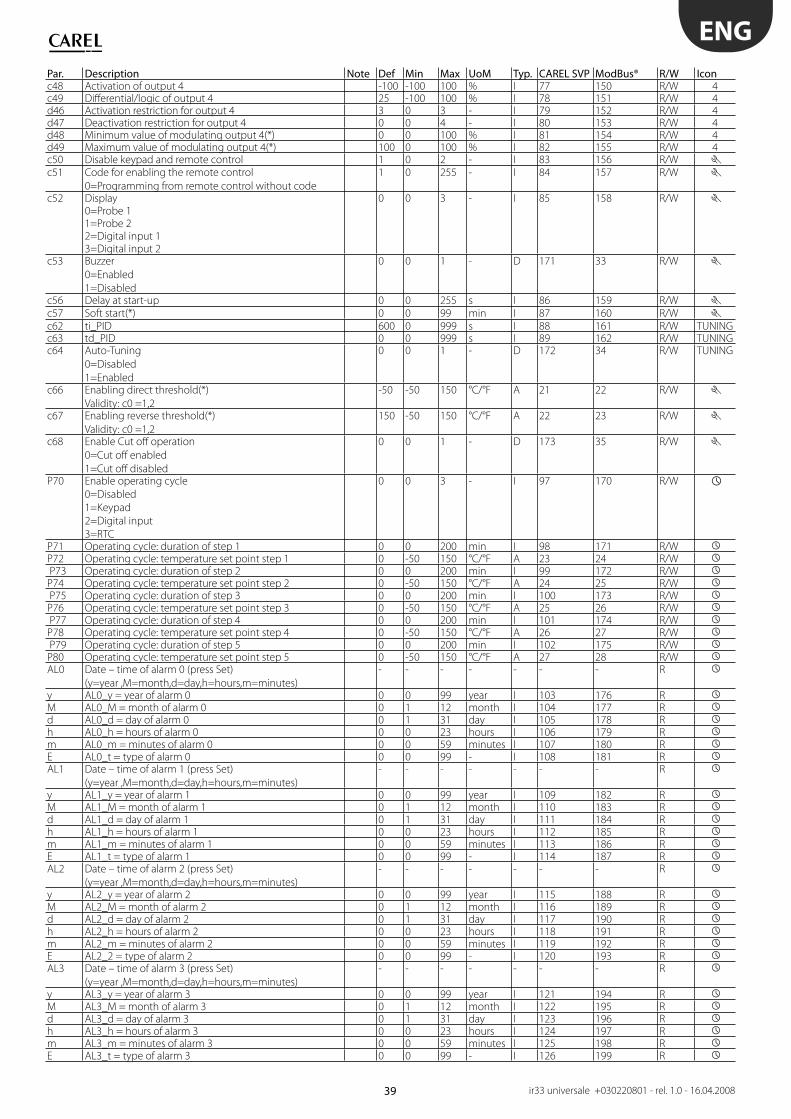
39
ENG
ir33 universale +030220801 - rel. 1.0 - 16.04.2008
Par. Description Note Def Min Max UoM Typ. CAREL SVP ModBus® R/W Iconc48 Activation of output 4 -100 -100 100 % I 77 150 R/W 4c49 Diff erential/logic of output 4 25 -100 100 % I 78 151 R/W 4d46 Activation restriction for output 4 3 0 3 - I 79 152 R/W 4d47 Deactivation restriction for output 4 0 0 4 - I 80 153 R/W 4d48 Minimum value of modulating output 4(*) 0 0 100 % I 81 154 R/W 4d49 Maximum value of modulating output 4(*) 100 0 100 % I 82 155 R/W 4c50 Disable keypad and remote control 1 0 2 - I 83 156 R/W c51 Code for enabling the remote control
0=Programming from remote control without code
1 0 255 - I 84 157 R/W
c52 Display0=Probe 11=Probe 22=Digital input 13=Digital input 2
0 0 3 - I 85 158 R/W
c53 Buzzer
0=Enabled
1=Disabled
0 0 1 - D 171 33 R/W
c56 Delay at start-up 0 0 255 s I 86 159 R/W c57 Soft start(*) 0 0 99 min I 87 160 R/W c62 ti_PID 600 0 999 s I 88 161 R/W TUNINGc63 td_PID 0 0 999 s I 89 162 R/W TUNINGc64 Auto-Tuning
0=Disabled
1=Enabled
0 0 1 - D 172 34 R/W TUNING
c66 Enabling direct threshold(*)
Validity: c0 =1,2
-50 -50 150 °C/°F A 21 22 R/W
c67 Enabling reverse threshold(*)
Validity: c0 =1,2
150 -50 150 °C/°F A 22 23 R/W
c68 Enable Cut off operation
0=Cut off enabled
1=Cut off disabled
0 0 1 - D 173 35 R/W
P70 Enable operating cycle
0=Disabled
1=Keypad
2=Digital input
3=RTC
0 0 3 - I 97 170 R/W
P71 Operating cycle: duration of step 1 0 0 200 min I 98 171 R/W P72 Operating cycle: temperature set point step 1 0 -50 150 °C/°F A 23 24 R/W P73 Operating cycle: duration of step 2 0 0 200 min I 99 172 R/W P74 Operating cycle: temperature set point step 2 0 -50 150 °C/°F A 24 25 R/W P75 Operating cycle: duration of step 3 0 0 200 min I 100 173 R/W P76 Operating cycle: temperature set point step 3 0 -50 150 °C/°F A 25 26 R/W P77 Operating cycle: duration of step 4 0 0 200 min I 101 174 R/W P78 Operating cycle: temperature set point step 4 0 -50 150 °C/°F A 26 27 R/W P79 Operating cycle: duration of step 5 0 0 200 min I 102 175 R/W P80 Operating cycle: temperature set point step 5 0 -50 150 °C/°F A 27 28 R/W AL0 Date – time of alarm 0 (press Set)
(y=year ,M=month,d=day,h=hours,m=minutes)
- - - - - - - R
y AL0_y = year of alarm 0 0 0 99 year I 103 176 R M AL0_M = month of alarm 0 0 1 12 month I 104 177 R d AL0_d = day of alarm 0 0 1 31 day I 105 178 R h AL0_h = hours of alarm 0 0 0 23 hours I 106 179 R m AL0_m = minutes of alarm 0 0 0 59 minutes I 107 180 R E AL0_t = type of alarm 0 0 0 99 - I 108 181 R AL1 Date – time of alarm 1 (press Set)
(y=year ,M=month,d=day,h=hours,m=minutes)
- - - - - - - R
y AL1_y = year of alarm 1 0 0 99 year I 109 182 R M AL1_M = month of alarm 1 0 1 12 month I 110 183 R d AL1_d = day of alarm 1 0 1 31 day I 111 184 R h AL1_h = hours of alarm 1 0 0 23 hours I 112 185 R m AL1_m = minutes of alarm 1 0 0 59 minutes I 113 186 R E AL1_t = type of alarm 1 0 0 99 - I 114 187 R AL2 Date – time of alarm 2 (press Set)
(y=year ,M=month,d=day,h=hours,m=minutes)
- - - - - - - R
y AL2_y = year of alarm 2 0 0 99 year I 115 188 R M AL2_M = month of alarm 2 0 1 12 month I 116 189 R d AL2_d = day of alarm 2 0 1 31 day I 117 190 R h AL2_h = hours of alarm 2 0 0 23 hours I 118 191 R m AL2_m = minutes of alarm 2 0 0 59 minutes I 119 192 R E AL2_2 = type of alarm 2 0 0 99 - I 120 193 R AL3 Date – time of alarm 3 (press Set)
(y=year ,M=month,d=day,h=hours,m=minutes)
- - - - - - - R
y AL3_y = year of alarm 3 0 0 99 year I 121 194 R M AL3_M = month of alarm 3 0 1 12 month I 122 195 R d AL3_d = day of alarm 3 0 1 31 day I 123 196 R h AL3_h = hours of alarm 3 0 0 23 hours I 124 197 R m AL3_m = minutes of alarm 3 0 0 59 minutes I 125 198 R E AL3_t = type of alarm 3 0 0 99 - I 126 199 R
40
ENG
ir33 universale +030220801 - rel. 1.0 - 16.04.2008
Par. Description Note Def Min Max UoM Type CAREL SVP ModBus® R/W IconAL4 Date – time of alarm 4 (press Set)
(y=year ,M=month,d=day,h=hours,m=minutes)
- - - - I - - R
y AL4_y = year of alarm 4 0 0 99 year I 127 200 R M AL4_M = month of alarm 4 0 1 12 month I 128 201 R d AL4_d = day of alarm 4 0 1 31 day I 129 202 R h AL4_h = hours of alarm 4 0 0 23 hours I 130 203 R m AL4_m = minutes of alarm 4 0 0 59 mins. I 131 204 R E AL4_t = type of alarm 4 0 0 99 - I 132 205 R ton Switch device on (press Set)
(d=day ,h=hour, m=minutes)
- - - - - - - R
d tON_d = on day 0 0 11 day I 133 206 R/W h tON_h = on hours 0 0 23 hours I 134 207 R/W m tON_m = on minutes 0 0 59 mins. I 135 208 R/W toff Switch device off (press Set)
(d=day ,h=hour, m=minutes)
- - - - - - - R
d tOFF_d = off day 0 0 11 day I 136 209 R/W h tOFF_h = off hours 0 0 23 hours I 137 210 R/W m tOFF_m = off minutes 0 0 59 mins I 138 211 R/W tc Date – time (press Set)
(y=year, M=month, d=day of month, u=day of week,
h=hours, m=minutes)
- - - - - - - R
y Date: year 0 0 99 year I 28 101 R/W M Date: month 1 1 12 month I 29 102 R/W d Date: day 1 1 31 day I 30 103 R/W u Date: day of the week (Monday, ...) 1 1 7 day I 31 104 R/W h Hours 0 0 23 hours I 32 105 R/W M Minutes 0 0 59 mins. I 33 106 R/W
(*) Functions active starting from software version higher than 1.0.
The default, minimum and maximum values of the temperature parameter refer to the unit of measure in °C. If changing the unit of measure, the
corresponding values must be entered.
7.1 Variables only accessible via serial connection
Description Def Min Max UoM Typ. CAREL SVP ModBus®(*) R/W DescriptionReading of probe 1 0 0 0 °C/°F A 1 2 R_TYPE Reading of probe 1Reading of probe 2 0 0 0 °C/°F A 2 3 R_TYPE Reading of probe 2Status of output 1 0 0 1 - D 139 1 R_TYPE Status of relay 1Status of output 2 0 0 1 - D 140 2 R_TYPE Status of relay 2Status of output 3 0 0 1 - D 141 3 R_TYPE Status of relay 3Status of output 4 0 0 1 - D 142 4 R_TYPE Status of relay 4Status of digital input 1 0 0 1 - D 144 6 R_TYPE Status of digital input 1Status of digital input 2 0 0 1 - D 145 7 R_TYPE Status of digital input 2Probe 2 fault alarm 0 0 1 - D 148 10 R_TYPE Probe 2 fault alarmImmediate external alarm 0 0 1 - D 149 11 R_TYPE Immediate external alarmHigh temperature alarm 0 0 1 - D 150 12 R_TYPE High temperature alarmLow temperature alarm 0 0 1 - D 151 13 R_TYPE Low temperature alarmDelayed external alarm 0 0 1 - D 152 14 R_TYPE Delayed external alarmImmediate external alarm with
manual reset
0 0 1 - D 153 15 R_TYPE Immediate external alarm with
manual resetRTC fault alarm 0 0 1 - D 154 16 R_TYPE RTC fault alarmEEPROM unit parameters alarm 0 0 1 - D 155 17 R_TYPE EEPROM unit parameters alarmEEPROM operating parameters alarm 0 0 1 - D 156 18 R_TYPE EEPROM operating parameters alarmMaximum time in calculation of
PID parameters
0 0 1 - D 157 19 R_TYPE Maximum time in calculation of
PID parametersPID gain null 0 0 1 - D 158 20 R_TYPE PID gain nullPID gain negative 0 0 1 - D 159 21 R_TYPE PID gain negativeIntegral & derivative time negative 0 0 1 - D 160 22 R_TYPE Integral & derivative time negativeMaximum time in calculation of
continuous gain
0 0 1 - D 161 23 R_TYPE Maximum time in calculation of
continuous gainStarting situation not suitable 0 0 1 - D 162 24 R_TYPE Starting situation not suitableSwitch controller On/Off 0 0 1 - D 174 36 R_W_TYPE Switch controller On/Off
(*) Functions active starting from software version higher than 1.0.
Type of variable : A =analogue, D=digital, I=integer
SVP= variable address with CAREL protocol on 485 serial card.
ModBus® : variable address with ModBus® protocol on 485 serial card.
The selection between CAREL and ModBus® protocol is automatic. For both of them the speed is fi xed to 19200 bit/s.
All the devices connected to the same network must feature the same serial parameters: - 8 data bit;
- 1 start bit;
- 2 stop bit;
- no parity check;
- 19200 baud rate.
41
ENG
ir33 universale +030220801 - rel. 1.0 - 16.04.2008
8. ALARMS
8.1 Types of alarmsThere are two types of alarms available:
high temperature (E04) and low temperature (E05); • serious alarms, that is, all the others.•
The data memory alarms E07/E08 always cause the control to shutdown.
“Alarm” mode (c0=5) can use one or more outputs to signal a low or
high temperature, probe disconnected or short-circuited alarm: see the
chapter on “Functions”. The eff ect of the outputs on the alarms in special
operation depends on the “dependence” parameter: see the chapter on
“Functions”.
The controller also indicates alarms due to faults on the controller itself,
on the probes or in the “Auto-Tuning” procedure. An alarm can also be
activated via an external contact. The display shows “Exy” alternating with
the standard display. At the same time, an icon fl ashes (spanner, triangle
or clock) and the buzzer may be activated (see the table below). If more
than one error occurs, these are shown in sequence on the display.
A maximum of 4 alarms are saved, in a FIFO list (AL0,AL1,AL2,AL3). The last
alarm saved can be read from parameter AL0 (see the list of parameters).
To mute the buzzer press Prg/mute.
8.2 Alarms with manual resetTo cancel the signal of an alarm with manual reset, once the causes • have ceased, press Prg/mute and UP for 5 seconds.
8.3 Display alarm queueAccess the list of Parameters, as described in paragraph 3.3.3.• Press • / until reaching parameter “AL0” (last error saved).
Press • Set, this accesses a submenu where the and buttons
can be used to scroll between the year, month, day, hours, minutes and
type of alarm activated. If the controller is not fi tted with the RTC, only
the type is saved.
From any of the parameters, pressing • Set returns to the parent
parameter “ALx”.
Example:
‘y07’ -> ‘M06’ -> ‘d13’ -> ‘h17’ -> ‘m29’ -> ‘E03’
indicates that alarm ‘E03’(alarm from digital input) occurred on 13 June
2007 at 17:29.
Example: display after error E03
42
ENG
ir33 universale +030220801 - rel. 1.0 - 16.04.2008
8.4 Table of alarmsMessage
on display
Cause of the alarm Icon on display Alarm relay Buzzer Reset Code
shown in
alarm queue
ALx_TYPE
Control action Checks/solutions
E01 Probe B1 fault fl ashing
The alarm relay
is activated
according to the
operating mode
and/or the
dependence
OFF automatic E01 Depends on
parameter c10
Check probe connections
E02 Probe B2 fault
fl ashing
OFF automatic E02 If c19=1 & c0=1/2,
as for E01, otherwise
control does not
stop.
Check probe connections
E03 Digital contact open
(immediate alarm) fl ashing
ON automatic E03 Based on parameter
c31
Check parameters
c29,c30,c31.
Check the external contact.E04 The temperature measured
by the probe has exceeded
the threshold P26 for a time
greater than P28.
fl ashing
ON automatic E04 No eff ect on control Check parameters P26,P27,
P28,P29
E05 The temperature measured
by the probe has fallen
below threshold P25 for a
time greater than P28.
fl ashing
ON automatic E05 No eff ect on control Check parameters P25,P27,
P28,P29
E03 Digital contact open
(delayed alarm) fl ashing
ON manual E03 Based on parameter
c31
Check parameters c29,c30,
c31,P28.
Check the external contact.E03 Digital contact open
(immediate alarm with
manual reset)fl ashing
ON manual E03 Based on parameter
c31
Check parameters
c29,c30,c31. Check the
external contact.E06 Real time clock fault
fl ashing
OFF automatic
/manual
- - Reset the clock time.
If the alarm persists,
contact service.E07 EEPROM error, unit
parameters fl ashingOFF automatic - Total shutdown Contact service
E08 EEPROM error, operating
parameters
fl ashing
OFF automatic - Total shutdown Reset default values using
the procedure described. If
the alarm persists, contact
service.
E09 Acquisition error.
Reached max. time in
calculation of PID parameters. fl ashing
ON manual - Auto-Tuning
stopped
Reset the alarm manually
or switch the controller off
and on again
E10 Calculation error:
PID gain null. fl ashingON manual - Auto-Tuning
stoppedE11 Calculation error:
PID gain negative fl ashingON manual - Auto-Tuning
stoppedE12 Calculation error:
Integral & deriv. time negative fl ashingON manual - Auto-Tuning
stoppedE13 Acquisition error.
Reached max. continuous time
in calculation of gain.fl ashing
ON manual - Auto-Tuning
stopped
E14 Error when starting.
Situation not suitable fl ashingON manual - Auto-Tuning
stopped
The alarms that occur during the Auto-Tuning procedure are not put in
the alarm queue.
8.5 Alarm parametersThe following parameters determine the behaviour of the outputs when
an alarm is active.
8.5.1 Status of the control outputs with probe alarm (parameter c10)
This determines the action on the control outputs when there is a control
probe alarm E01, which may be one of the four responses envisaged.
When OFF is selected, the controller shuts down immediately and the
timers are ignored. When ON is selected, on the other hand, the “Delay
between activations of two diff erent relay outputs” (parameter c6) is
observed. When alarm E01 is resolved, the controller restarts normally
and the alarm output, if set, terminates the signal (see mode 5). On the
other hand, both the signal on display and the buzzer remain active until
Prg/mute is pressed.
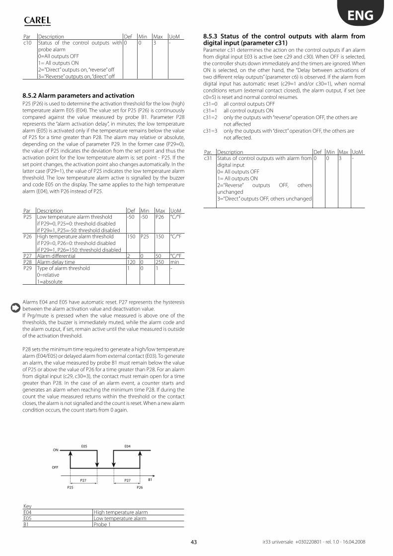
43
ONE05 E04
OFF
P25 P26
B1P27 P27
ENG
ir33 universale +030220801 - rel. 1.0 - 16.04.2008
Par Description Def Min Max UoMc10 Status of the control outputs with
probe alarm
0=All outputs OFF
1= All outputs ON
2=”Direct” outputs on, “reverse” off
3=“Reverse” outputs on, “direct” off
0 0 3 -
8.5.2 Alarm parameters and activation
P25 (P26) is used to determine the activation threshold for the low (high)
temperature alarm E05 (E04). The value set for P25 (P26) is continuously
compared against the value measured by probe B1. Parameter P28
represents the “alarm activation delay”, in minutes; the low temperature
alarm (E05) is activated only if the temperature remains below the value
of P25 for a time greater than P28. The alarm may relative or absolute,
depending on the value of parameter P29. In the former case (P29=0),
the value of P25 indicates the deviation from the set point and thus the
activation point for the low temperature alarm is: set point - P25. If the
set point changes, the activation point also changes automatically. In the
latter case (P29=1), the value of P25 indicates the low temperature alarm
threshold. The low temperature alarm active is signalled by the buzzer
and code E05 on the display. The same applies to the high temperature
alarm (E04), with P26 instead of P25.
Par Description Def Min Max UoMP25 Low temperature alarm threshold
if P29=0, P25=0: threshold disabled
if P29=1, P25=-50: threshold disabled
-50 -50 P26 °C/°F
P26 High temperature alarm threshold
if P29=0, P26=0: threshold disabled
if P29=1, P26=150: threshold disabled
150 P25 150 °C/°F
P27 Alarm diff erential 2 0 50 °C/°FP28 Alarm delay time 120 0 250 minP29 Type of alarm threshold
0=relative
1=absolute
1 0 1 -
Alarms E04 and E05 have automatic reset. P27 represents the hysteresis
between the alarm activation value and deactivation value.
If Prg/mute is pressed when the value measured is above one of the
thresholds, the buzzer is immediately muted, while the alarm code and
the alarm output, if set, remain active until the value measured is outside
of the activation threshold.
P28 sets the minimum time required to generate a high/low temperature
alarm (E04/E05) or delayed alarm from external contact (E03). To generate
an alarm, the value measured by probe B1 must remain below the value
of P25 or above the value of P26 for a time greater than P28. For an alarm
from digital input (c29, c30=3), the contact must remain open for a time
greater than P28. In the case of an alarm event, a counter starts and
generates an alarm when reaching the minimum time P28. If during the
count the value measured returns within the threshold or the contact
closes, the alarm is not signalled and the count is reset. When a new alarm
condition occurs, the count starts from 0 again.
KeyE04 High temperature alarmE05 Low temperature alarmB1 Probe 1
8.5.3 Status of the control outputs with alarm from digital input (parameter c31) Parameter c31 determines the action on the control outputs if an alarm
from digital input E03 is active (see c29 and c30). When OFF is selected,
the controller shuts down immediately and the timers are ignored. When
ON is selected, on the other hand, the “Delay between activations of
two diff erent relay outputs” (parameter c6) is observed. If the alarm from
digital input has automatic reset (c29=1 and/or c30=1), when normal
conditions return (external contact closed), the alarm output, if set (see
c0=5) is reset and normal control resumes.
c31=0 all control outputs OFF
c31=1 all control outputs ON
c31=2 only the outputs with “reverse” operation OFF, the others are
not aff ected
c31=3 only the outputs with “direct” operation OFF, the others are
not aff ected.
Par. Description Def Min Max UoMc31 Status of control outputs with alarm from
digital input
0= All outputs OFF
1= All outputs ON
2=“Reverse” outputs OFF, others
unchanged
3=“Direct” outputs OFF, others unchanged
0 0 3 -

44
ENG
ir33 universale +030220801 - rel. 1.0 - 16.04.2008
9. TECHNICAL SPECIFICATIONS AND PRODUCT CODES
9.1 Technical specifi cations
Model Voltage PowerPower supply IR33x(V,W,Z,D,A,B,E)7Hx(B,R)20 115/230Vac(-15% to +10%), 50/60Hz 6VA, 50mA~ max
DN33x(V,W,Z,A,B,E)7Hx(B,R)20
IR33x(V,W,Z,D,A,B,E)7LR20,
DN33x(V,W,Z,A,B,E)7LR20
12/24Vac(-10% to +10%), 50/60Hz 4VA, 300mA~ max12/30Vdc 300 mA maxOnly use SELV power supply
Insulation guaranteed by
the power supply
IR33x(V,W,Z,D,A,B,E)7Hx(B,R)20
DN33x(V,W,Z,A,B,E)7Hx(B,R)20
insulation from very low voltage parts reinforced6 mm in air, 8 mm on surface
3750V insulation
insulation from relay outputs basic3 mm in air, 4 mm on surface1250V insulation
IR33x(V,W,Z,D,A,B,E)7LR20
DN33x(V,W,Z,A,B,E)7LR20
insulation from very low voltage parts to be guaranteed externally by safety
transformerinsulation from relay outputs reinforced
6 mm in air, 8 mm on surface3750V insulation
Inputs B1 (PROBE1) NTC or NTC extended range or PTC or PT1000B2 (PROBE2)DI1 voltage-free contact, contact resistance < 10Ω, closing current 6mADI2Maximum distance of probes and digital inputs less than 10mNote: in the installation, keep the power and load connections separate from the probe, digital inputs, repeater display and
supervisor cables.
Type of probe Std. CAREL NTC 10kΩ at 25°C, range from –50T90°C
measurement error: 1°C in range from –50T50°C3°C in range from +50T90°C
High temperature NTC 50kΩ at 25°C, range from –40T150°Cmeasurement error: 1.5°C in range from
–20T115°C4°C in range outside of
-20T115°CPTC 985Ω at 25°C, range from -50T150°C
measurement error 2°C in range from –50T50°C4°C in range from +50T150°C
Type of probe PT1000 1097Ω at 25°C, range from -50T150°Cmeasurement error: 3°C in range from –50T0°C
5°C in range from 0T150°C
Relay outputs EN60730-1 UL 873models relays 250V~ oper. cycles 250V~ oper. cyclesIR33x(V,W,Z,B,E)7LR20
DN33x(V,W,Z,B,E)7LR20
R1,R2 8 (4)A N.O. 100000 8A res 2FLA
12LRA C300
30000
IR33x(V,W,Z,B,E)7Hx(R,B)20
DN33x(V,W,Z,B,E)7Hx(R,B)20
R3,R4 6 (4)A N.C.
SSR outputs modelsIR33x(D,A)7LR20 D = 1 SSR output Max. output voltage: 12 VdcDN33x(D,A)7LR20 Output resistance: 600 ΩIR33x(D,A)7Hx(R,B)20 DN33x(D,A)7Hx(R,B)20 A = 4 SSR output Max. output current: 20 mA
0 to 10 Vdc outputs modelsIR33B7LR20
DN33B7LR20
B = 1 relay + 1 x 0 to 10Vdc Typical ramp time (10%-90%): 1 sMax output ripple: 50 mV
IR33E7Hx(R,B)20
DN33E7Hx(R,B)20
E = 2 relays + 2 x 0 to 10Vdc Max output current: 5 mA
Insulation guaranteed by
the outputs
insulation from very low voltage parts/insulation between relay outputs & 0 to 10Vdc
outputs
reinforced
6 mm in air, 8 mm on surface3750V insulation
insulation between outputs basic3 mm in air, 4 mm on surface1250V insulation
IR receiver On all modelsClock with backup
battery
IR33x(V,W,Z,D,A,B,E)7HB20, DN33x(V,W,Z,A,B,E)7HB20
Buzzer available on all modelsClock error at 25°C ± 10ppm (±5.3min/year)
Error in range -10T60°C -50ppm(±27 min/year)Ageing < ±5ppm (±2.7min/year)Discharge time 6 months typical (8 months maximum)Recharge time 5 hours typical (< 8 hours maximum)

45
ENG
ir33 universale +030220801 - rel. 1.0 - 16.04.2008
Operating temperature IR33xxxxxx: -10T60 °C
DN33x(V,W,Z,D,A,B,E)7LR20: -10T55°C
DN33x(V,W,Z,D,A,B,E)7Hx(R,B)20: -10T50°COperating humidity <90% rH non-condensingStorage temperature -20T70 °CStorage humidity <90% rH non-condensingFront panel index of protection IR33: assembly on smooth and indeformable panel with IP65 gasket
DN33: front panel IP40, complete controller IP20Construction of control device Integrated electronic control deviceEnvironmental pollution 2 normalPTI of the insulating materials Printed circuits 250, plastic and insulating materials 175Period of stress across the insulating parts LongClass of protection against voltage surges Category 2Type of action and disconnection 1B relay contacts (microswitching)Classifi cation according to protection against electric shock Class 2 when appropriately integratedDevice designed to be hand-held or integratedin hand-held devices
No
Software class and structure Class AFront panel cleaning Only use neutral detergents and waterCarel serial network interface External, available on all modelsProgramming key Available on all models
Type of connection Size Max current
Connections model relays/ SSR power supply probes
IR33x(V,W,Z,D,A,B,E)7x(H,L)x(R,B)20
DN33x(V,W,Z,A,B,E)7x(H,L)x(R,B)20
plug-in plug-in plug-in for cables from
0.5 to 2.5 mm2
12A
Correct sizing of the power and connection cables between the controller and the loads is the responsibility of the installer.In the max load and max operating temp. conditions, the cables used must be suitable for operation up to 105°C.
Case plastic IR33x(V,W,Z,D,A,B,E)7x(H,L)x(R,B)20
DN33x(V,W,Z,A,B,E)7x(H,L)x(R,B)20
dimensions IR33:34.4x76.2x79mm
DN33:111x70x60mounting
depth
IR33: 70.5mm
DN33: 60mm
Assembly IR33: on smooth and indeformable panel DN33 :DIN rail IR33 :side fastening brackets, to be pressed in fully
drilling template IR33:dimensions 28.8±0.2 x 70.8±0.2mm
DN33(display):dimensions 28.8±0.2 x 70.8±0.2mm
Display digits 3 digit LED
display from –99 to 999
operating status indicated with graphic icons on the display
Keypad 4 silicone rubber buttons
9.2 Cleaning the controllerWhen cleaning the controller do not use ethanol, hydrocarbons (petrol), ammonia and by-products. Use neutral detergents and water.
9.3 Product codes
CODE DescriptionFlush mount DIN rail mountingIR33V7HR20 DN33V7HR20 2 NTC/PTC,PT1000 input, 1 relay, buzzer, IR receiver, 115/230VIR33V7HB20 DN33V7HB20 2 NTC/PTC,PT1000 input, 1 relay , buzzer, IR receiver, RTC, 115/230VIR33V7LR20 DN33V7LR20 2 NTC/PTC,PT1000 input, 1 relay , buzzer, IR receiver, 12/24VIR33W7HR20 DN33W7HR20 2 NTC/PTC,PT1000 input, 2 relays, buzzer, IR receiver, 115/230VIR33W7HB20 DN33W7HB20 2 NTC/PTC,PT1000 input, 2 relays, buzzer , IR receiver, RTC, 115/230VIR33W7LR20 DN33W7LR20 2 NTC/PTC,PT1000 input, 2 relays, buzzer, IR receiver, 12/24VIR33Z7HR20 DN33Z7HR20 2 NTC/PTC,PT1000 input, 4 relays, buzzer, IR receiver, 115/230VIR33Z7HB20 DN33Z7HB20 2 NTC/PTC,PT1000 input, 4 relays , buzzer, IR receiver, RTC, 115/230VIR33Z7LR20 DN33Z7LR20 2 NTC/PTC,PT1000 input, 4 relays , buzzer, IR receiver, 12/24VIR33A7HR20 DN33A7HR20 2 NTC/PTC,PT1000, 4 SSR, buzzer, IR receiver, 115/230VIR33A7HB20 DN33A7HB20 2 NTC/PTC,PT1000 input, 4 SSR, BUZZER, IR receiver, RTC, 115/230VIR33A7LR20 DN33A7LR20 2 NTC/PTC,PT1000 input, 4 SSR, buzzer, IR receiver, 12/24VIR33D7HR20 - 2 NTC/PTC,PT1000 input, 1 SSR, buzzer, IR receiver, 115/230VIR33D7HB20 - 2 NTC/PTC,PT1000 input, 1 SSR, buzzer, IR receiver, RTC, 115/230VIR33D7LR20 - 2 NTC/PTC,PT1000 input, 1 SSR, buzzer, IR receiver, 12/24VIR33B7HR20 DN33B7HR20 2 NTC/PTC,PT1000 input, 1 relay + 1 AO, buzzer, IR receiver, 115/230VIR33B7HB20 DN33B7HB20 2 NTC/PTC,PT1000 input, 1 relay + 1 AO, buzzer, IR receiver, RTC, 115/230VIR33B7LR20 DN33B7LR20 2 NTC/PTC,PT1000 input, 1 relay + 1 AO, buzzer, IR receiver, 12/24VIR33E7HR20 DN33E7HR20 2 NTC/PTC,PT1000 input, 2 relays + 2 AO, buzzer, IR receiver, 115/230VIR33E7HB20 DN33E7HB20 2 NTC/PTC,PT1000 input, 2 relays + 2 AO, buzzer, IR receiver, RTC, 115/230VIR33E7LR20 DN33E7LR20 2 NTC/PTC,PT1000 input, 2 relays + 2 AO, buzzer, IR receiver, 12/24V
IROPZKEY00 Programming keyIROPZKEYA0 Programming key with power supply
IROPZ48500 RS485 serial interfaceIROPZ485S0 RS485 serial interface with automatic recognition of TxRx+ & TxRx-
IROPZSER30 RS485 serial card for DN33CONV0/10A0 Analogue output moduleCONV0NOFF0 ON/OFF output moduleIRTRUES000 Remote control

46
ENG
ir33 universale +030220801 - rel. 1.0 - 16.04.2008
9.4 Software revisions
REVISION Description1.0 Functions active starting from software version higher than
1.0FUNCTION ParameterSoft start c570 to 10 V outputs c19=5,6 / c66, c67
d36, d40, d44, d48d37, d41, d45, d49


Headquarters
CAREL S.p.A.
Via dell’Industria, 11 - 35020 Brugine - Padova (Italy)Tel. (+39) 0499 716611 - Fax (+39) 0499 [email protected] - www.carel.com
Subsidiaries:
CAREL Asia LtdRm. 11, 8/F., Shatin Galleria,18 Shan Mei St., Fotan, Shatin - Hong KongTel. (+852) 2693 6223 - Fax: (+852) 2693 6199e-mail: [email protected] - www.carelhk.com
CAREL Australia Pty LtdPO Box 6809, Silverwater B.C. N.S.W. 1811Unit 37, 11-21 Underwood Rd Homebush N.S.W. 2140Tel: (+612) 8762 9200 - Fax: (+612) 9764 6933e-mail: [email protected] - www.carel.com.au
CAREL China - CAREL Electronic (Suzhou) Co. Ltd.No. 26, 369 Lushan Road,Suzhou City, Jiangsu Province,215129 P.R. of ChinaTel: (+865) 12 66628098 - Fax: (+865) 12 66626631e-mail: [email protected] - www.carel-china.com
CAREL Deutschland GmbHAm Spielacker, 34, 63571 Gelnhausen (Germany)Tel. (+49) 6051 96290 - Fax (+49) 6051 962924e-mail: [email protected] – www.carel.de
CAREL France Sas32, rue du Champ Dolin - 69800 Saint Priest, FranceTel. (+33) 472 47 88 88 - Fax (+33) 478 90 08 08e-mail: [email protected] – www.carelfrance.fr
CAREL IbéricaAutomatización y control ATROL S.L.Comte Borrell, 15 - 08015 BarcelonaTel. (+34) 933 298 700 - Fax. (+34) 933 298 700
DELEGACIÓN CENTRO
Edifi cio Burgosol C/Comunidad de Madrid, 35 bis, Ofi cina 4728230 Las Rozas - MADRIDtel.(+34) 91 637 59 66 - Fax: (+34) 91 637 32 07e-mail: [email protected] - www.carel.es
CAREL Sud America Ltda
Avenida Dourado, 587 - Cep. 13.280-000 Vinhedo – São Paulo (Brasil)Tel (+55) 19 38 26 25 65 - Fax (+55) 19 38 26 25 54e-mail: [email protected] – www.carel.com.br
CAREL U.K. Ltd
Unit 6, Windsor Park Industrial Estate, 50 Windsor AvenueMerton SW19 2TJ, London (United Kingdom)Tel. (+44) 208 545 9580 - Fax (+44) 208 543 8018e-mail: [email protected] – www.careluk.co.uk
CAREL U.S.A. L.L.C
385 South Oak StreetManheim, PA 17545, Pennsylvania (USA)Tel. (+1) 717-664-0500 - Fax (+1) 717-664-0449e-mail: [email protected] - www.carelusa.com
www.carel.com
Affi liates:
CAREL Korea Co. Ltd.A-901,Chung Ang Circ. Complex1258 Kuro Bon-Dong, Kuro-KU,Seoul-KOREATel: (+82) 02 2068 8001Fax: (+82) 02 2068 8005e-mail: [email protected] - www.carel.co.kr
CAREL IrelandFarrahVale Controls & Electronics Ltd 28E Ashbourne Business CentreCounty Meath – IRELANDTel: (+353) 1 8353745Fax: (+353) 1 8353681www.carel.com - [email protected]
CAREL Spol (Czech and Slovakia) s.r.o.Prazska 298
250 01 Brandys nad Labem, Czech Republic.Tel: (+420) 326 377 729Fax: (+420) 326 377 730e-mail: [email protected] - www.carel-cz.cz
CAREL Thailand Co., Ltd.444 4th Floor OlympiaThai Building, Ratchadapisek Road,Samsennok, Huaykwang, Bangkok 10310 ThailandTel: (+66) 2 513 5610Fax: (+66) 2 513 5611e-mail: [email protected] - www.carel.co.th
CAREL TurkeyCFM Sogutma ve Otomasyon San. Tic. LTD1201 Sok. No: 13/Z 21 Izmir – TURKEYTel: (+90) 232 4590888Fax: (+90) 232 4593435www.cfmsogutma.com - [email protected]
All trademarks hereby referenced are
the property of their respective owners.
CAREL is a registered trademark of
CAREL S.p.A. in Italy and/or other countries.
© CAREL S.p.A. 2008 all rights reserved
CAREL reserves the right to modify the features of its products
without prior notice.
ir3
3 u
niv
ers
ale
+0
30
22
08
01
- r
el.
1.0
- 1
6.0
4.2
00
8
CARE
L re
serv
es th
e rig
ht to
mod
ify o
r cha
nge
its p
rodu
cts w
ithou
t prio
r not
ice.